abstract - msc software corporationweb.mscsoftware.com/.../fev_powertrain_dynamics.pdf ·...
TRANSCRIPT
Martin Rebbert and Philipp Kley, FEV Motorentechnik GmbH: Powertrain Dynamics Applications using "ADAMS/Engine powered by FEV" Part II: Cranktrain Dynamics
ABSTRACT In development processes of modern powertrains virtual prototyping methods become more and more important. On one hand numerical simulations save development time and expenses replacing expensive test rig investigations and on the other hand they help the development engineers understanding the dynamics of the subsystems in detail. In general it can be distinguished between special software and multi purpose simulation software. Previous engine development processes have shown that neither the specialized engine programs nor the multi purpose software are able to match all requirements of modern development processes alone. Only a combination of both can deliver the specific acknowledgment on one hand and the flexibility in usage on the other hand.
Therefore it has been decided at FEV Motorentechnik to set up specific software which bases on the standard components (e.g. Solver) of multi purpose software. Since it is possible to include flexible structures from Finite Element Analysis (FEA) into Multibody System Simulation (MSS), ADAMS appears to be the perfect base for engine specific add ons. The Dynamics of subsystems can be simulated as well as the structural dynamics of single components. With ADAMS/ENGINE the product line already delivers a good architecture for simulation activities embedded into powertrain development processes.
A strategic partnership was formed between MDI and FEV to combine the strength of both companies. Beneath enhancements of existing modules the development of the new cranktrain module is the first common project. For this FEV delivers years of experience in cranktrain simulation while MDI puts the ADAMS/Engine architecture and know how in software engineering at disposal.
The development of the cranktrain module is split up into two parts: The first part is based on rigid bodies and simplified flexibility approaches. Three levels of refinement will be available for the description of the crankshaft: -rigid crankshaft -torsional flexible crankshaft -torsional and bending flexible crankshaft using a beam approach The user can easily switch between these approaches depending on the results that are expected. For an evaluation of the free forces for example the rigid approach is sufficient. Additional Features that will be included in the cranktrain module are: -Engine Mounts (rubber- and hydro-), -Flywheel (single and dual mass), -Torsional vibration damper (rubber and viscous), -Hydrodynamic plain bearings, -Balancing shafts.
The second part of the cranktrain module development part contains flexible body approaches for crankshaft and engine block. It is perfect to deliver highly accurate boundary conditions for stress analysis and NVH investigations.
Most of the methodology to be implemented has been used and verified successfully in engineering projects before. This paper describes some of these features and shows examples of elements currently being developed.

CAE IN THE MODERN POWERTRAIN DEVELOPMENT PROCESS
There are many areas of CAE applications on combustion engines. Beneath the thermodynamics of the combustion and fluid dynamics of the intake and exhaust systems mechanical simulations are a basic part of the engine development process. Fig. 1 shows the typical subsystems of the engine, that are designed with simulation support.
In the case of the mechanical subsystems, shown on the left hand side, design improvements are expected from simulation work, mainly focusing on: - Component stresses and durability, - Lubrication, friction and wear out, - Noise and vibrations.
Intake Gas Dynamics
Intake Gas Dynamics
Exhaust Gas Dynamics
Exhaust Gas Dynamics
CombustionCombustion
CranktrainCranktrain
Valve TrainValve Train
Timing DriveTiming Drive
AccessoriesAccessories
Accessory Drive
Accessory Drive
Piston / Piston Ring
Piston / Piston Ring
Fig. 1: Engine CAE Areas
To ensure efficiency when including CAE into development processes, it is important, that the targets of simultaneous engineering techniques are fulfilled. This means, that valuable results must be available after time periods that are reasonable concerning the current project phase, because in the tight frame of modern development processes it is not possible to wait for simulation results. On the other hand the quality of the results has to be sufficient to make unique design decisions. Especially in the first development phases, when no prototype is available, the simulation results are often the only decision base and must be reliable. A mayor design change after the first prototype produces a large amount of additional costs and often leads to project delay.
An additional problem for the CAE engineers is the fact, that the expectations on response time and results quality are continuously changing during the development. In the very early concept phase evaluations of rough tendencies may be sufficient but have to be delivered quickly. In a detailed design phase more time may be available, but the results have to be more accurate.
Fig. 2 shows the CAE support in the pre-prototype phases of an engine development project. To support all three phases, concept, layout and detailed design, the used CAE software must
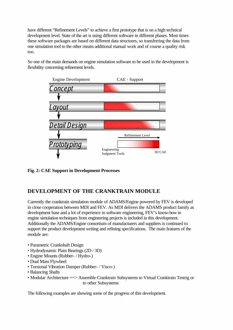
have different “Refinement Levels” to achieve a first prototype that is on a high technical development level. State of the art is using different software in different phases. Most times these software packages are based on different data structures, so transferring the data from one simulation tool to the other means additional manual work and of course a quality risk too.
So one of the main demands on engine simulation software to be used in the development is flexibility concerning refinement levels.
Engineering Judgment Tools 3D CAE
Engine Development CAE - Support
Prototyping
Detail Design
Layout
Concept
Refinement Level
Fig. 2: CAE Support in Development Processes
DEVELOPMENT OF THE CRANKTRAIN MODULE
Currently the cranktrain simulation module of ADAMS/Engine powered by FEV is developed in close cooperation between MDI and FEV. As MDI delivers the ADAMS product family as development base and a lot of experience in software engineering, FEV’s know-how in engine simulation techniques from engineering projects is included in this development. Additionally the ADAMS/Engine consortium of manufacturers and suppliers is continued to support the product development writing and refining specifications. The main features of the module are: • Parametric Crankshaft Design • Hydrodynamic Plain Bearings (2D / 3D) • Engine Mounts (Rubber- / Hydro-) • Dual Mass Flywheel • Torsional Vibration Damper (Rubber- / Visco-) • Balancing Shafts • Modular Architecture ==> Assemble Cranktrain Subsystems to Virtual Cranktrain Testrig or to other Subsystems
The following examples are showing some of the progress of this development.

Crankshaft Refinement Levels
The existing architecture of ADAMS/Engine powered by FEV is the perfect base for flexible engine simulation software. Beneath the template based structure, that decouples the data from the model topology and the technique of working with communicators that allows a flexible assembly of the subsystems, the flexibility regarding refinement levels is one of the main features. The possibility of simply switching between several valve spring approaches in the existing valve train module is only one example.
Consequently the idea of including different approaches in the same architecture will be continued developing the crank train module. To get a first idea about the dynamics it is often sufficient to know about the free forces and reaction torques of a new cranktrain design. For this, an approach using a rigid crankshaft, connected with constraints to the main bearings and the con rods is used. Due to the low number of degrees of freedom it is expected to be very fast. The next refinement level allows the investigation of torsional vibrations. Each throw is modeled as one rigid part. The spring connector between two throws represents the torsional stiffness of them. A parametric beam model represents the torsional and bending stiffness of the crankshaft. After FEA models are available the crankshaft and other components can be included as flexible structures using ADAMS/Flex.
Fig. 3 shows the technical realization for setting up the crankshaft component in four different levels of refinement. Level one to three are exchangeable easily in one template, the 4th level requires an additional template.
Refinement Levels at Cranktrain SimulationLevel 1: Rigid Crankshaft
Part: Throw Part: Throw
Joint: Fixed Part: Dummy(no Geometry, no Inertia)
Joint: Universal
Coincident(=no distance)
Level 2: Torsion Flexible CrankshaftJoint: Revolute+ Force: RSPD
Joint: Universal
Part: Throw Part: Throw
Part: Dummy(no Geometry,no Inertia)
Coincident (=no distance)
Level 4: FEA Flexible Crankshaft
Level 3: Beam Flexible Crankshaft
Part (geometry based)
Marker
Beam
RefinementLevel
RefinementLevel
Fig. 3: Refinement Levels at Cranktrain Simulations
Generic Cranktrain Parametrics
A really new feature of the Cranktrain module is a predefined generic parametrics, that supports the user in the template builder mode, positioning the construction frames. Based on the input of a small number of global parameters such as cylinder distance, stroke, bank angles and ignition order the positions and orientations of main bearings, crank pins, con rods

and pistons are calculated automatically. Using this feature the geometry of almost every common cranktrain design can be defined. However, the advanced user will still be able to use his own parametrics, or expand the predefined global parametrics for his own needs.
With the definition of three construction frames for each cylinder as shown in Fig. 4 the geometry of a usual cranktrain is completely defined. Even cranktrains, showing an offset between the centerline of the cylinder liners and crankshaft rotation axis (e.g. the VR design) are captured by this methodology.
The location of the cylinder reference frame describes the base point of the cylinder, normally located on the crankshaft rotation axis. For an offset design, as described above it is located on the liner axis at the nearest position to the crankshaft rotation axis. Its orientation describes the liner axis itself.
The crank pin position is also described by a construction frame oriented with one axis pointing radial from the crankshaft rotation axis. It is normally used to define the crank pin of the crankshaft and the con rod big eye center.
The piston position and orientation is located at the center of the piston pin and points with one axis parallel to the cylinder liner centerline (coincident if no piston pin offset is specified). This frame is useful for defining the con rod upper end and the piston location and orientation.
The piston liner connection is modeled using constraints for the crank train module. However, the implementation of a simulation module for piston secondary motion is planned for the future. In this case one additional frame, representing for example the piston position at TDC may become necessary for a unique description of the liner position.
bank_angle
crank_offset
Cylinder Reference
Crank Pin Position
Piston Position &Orientation
Generic Parametrics forn Cylinders on m BanksUsing Construction Frames
Open Architecture using Cranktrain Templates
Fig. 4: Parametric Description of Cranktrain Geometry

Hydrodynamic Plain Bearings
As soon as interior forces and moments of the cranktrain are of interest, an accurate approach for the highly nonlinear plain bearings is necessary. Experience has shown, that EHD approaches, considering the backward influence of the local deformations of the pins and shells on the oil pressure distribution are helpful to learn about the hydrodynamic details of the bearing itself, but lead to performance disadvantages due to the fact, that the Reynolds Differential Equation has to be solved for a large number of degrees of freedom in a closed loop with the dynamic equations of motions of the dynamic system.
It is well known, that HD approaches, that decouple the hydrodynamic behavior from the structural dynamic behavior do not deliver quantitative accurate pin orbital curves and hydrodynamic details as e.g. maximum oil pressures, but are absolutely sufficient to determine the forces in the bearing and their influence on the cranktrain subsystem. An additional problem is, that most HD approaches are strictly two-dimensional, which means, that they neglect the influence of bearing misalignment.
FEV developed a three dimensional HD approach, that solves the Reynold’s Equation considering misalignment and stores the results in characteristic databases. Simulating the dynamic cranktrain subsystem in ADAMS, a solver subroutine reads eccentricity and misalignment out off the model, accesses these databases and applies the forces and moments in the model for each time and iteration step, as Fig. 5 shows.
HD Reaction Force DatabaseHD Reaction
Force Database
3-dimensional Solution of
Reynolds Equation
3-dimensional Solution of
Reynolds Equation
ADAMS/SOLVER SUBROUTINES
ADAMS/SOLVER SUBROUTINES Read States
Access Database
Apply Force
Fig. 5: Hydrodynamic Plain Bearings
This methodology has been used at FEV in several research and development projects and is known as very stable and quick. It has been successfully verified by comparing results with test rig measurement data [2].
Engine Mounts
The implementation of the engine mount elements is also included in the cranktrain module, because they have to react mostly the forces and moments of the cranktrain. Two types of engine mounts are common for the vehicle application of combustion engines: Rubber mounts and hydro mounts. Both kinds of engine mounts show a nonlinear behavior in general.
A nonlinear displacement dependency, mostly depending on specific mount geometries has to be considered and the frequency dependent damping behavior of the material (rubber) is also not neglectable.
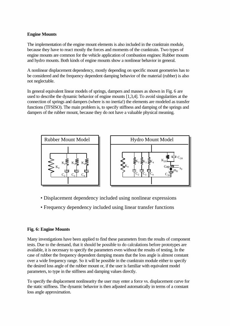
In general equivalent linear models of springs, dampers and masses as shown in Fig. 6 are used to describe the dynamic behavior of engine mounts [1,3,4]. To avoid singularities at the connection of springs and dampers (where is no inertia!) the elements are modeled as transfer functions (TFSISO). The main problem is, to specify stiffness and damping of the springs and dampers of the rubber mount, because they do not have a valuable physical meaning.
K0
K4K3K2
C4C3C2
Rubber Mount Model
K0
K4K3K2
C4C3C2
K2H
C2H
C3H
s0Gap
mH
Hydro Mount Model
• Displacement dependency included using nonlinear expressions
• Frequency dependency included using linear transfer functions
Fig. 6: Engine Mounts
Many investigations have been applied to find these parameters from the results of component tests. Due to the demand, that it should be possible to do calculations before prototypes are available, it is necessary to specify the parameters even without the results of testing. In the case of rubber the frequency dependent damping means that the loss angle is almost constant over a wide frequency range. So it will be possible in the cranktrain module either to specify the desired loss angle of the rubber mount or, if the user is familiar with equivalent model parameters, to type in the stiffness and damping values directly.
To specify the displacement nonlinearity the user may enter a force vs. displacement curve for the static stiffness. The dynamic behavior is then adjusted automatically in terms of a constant loss angle approximation.
At small displacements the hydro mount acts very similar to the rubber mount. Beyond a specific displacement value a valve closes, so that oil will flow through a narrow channel which results in additional inertia and damping. So for the hydro mount the following parameters have to be specified additionally: The gap height (s0), the fluid damping outside the channel (C2H), the fluid damping inside the channel (C3H), the fluid stiffness (K2H) and the effective fluid inertia (mH). For the behavior of the rubber part of the hydro mount it is again possible to specify either the loss angle or the three stiffness and damping values.
To give the user additional information about the dynamic behavior of a mount the frequency dependency can be displayed as transfer function (amplitude and loss angle) for both types of engine mounts.
SIMULATION EXAMPLES
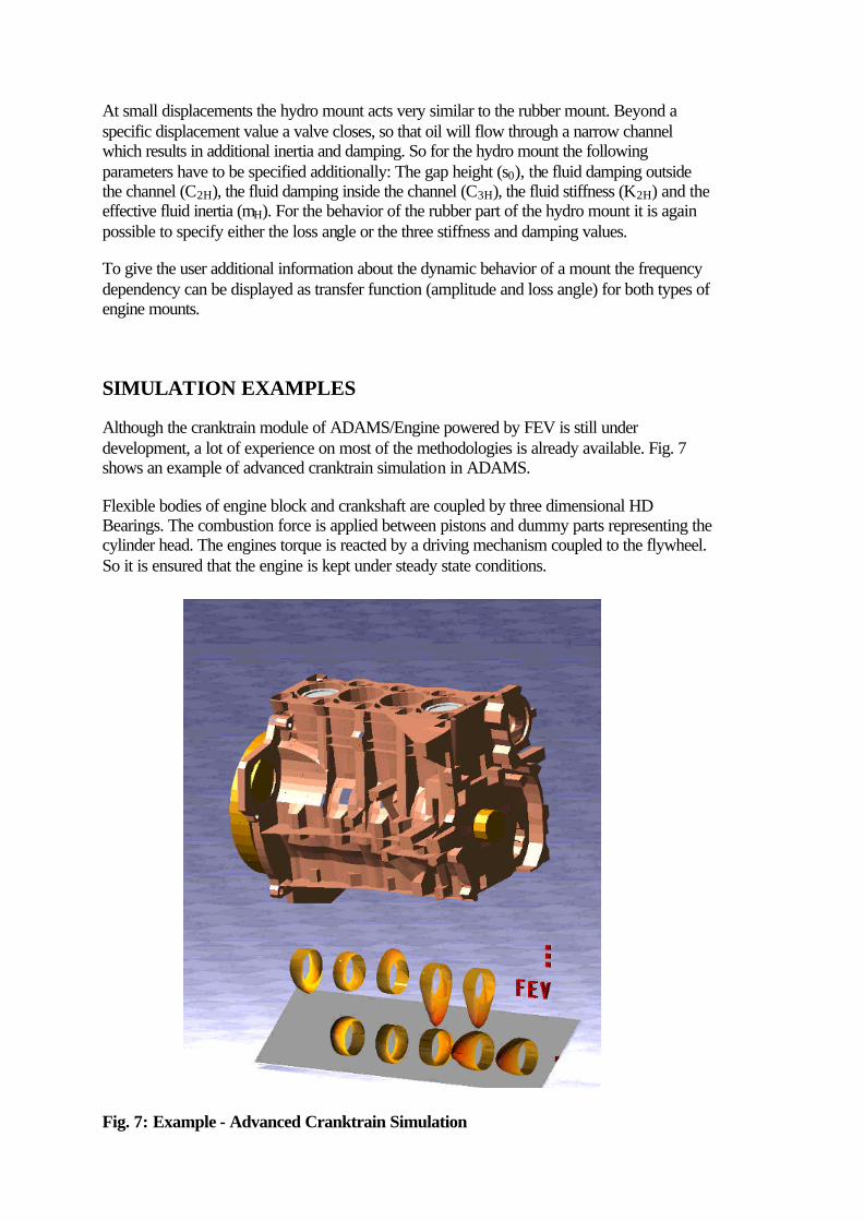
Although the cranktrain module of ADAMS/Engine powered by FEV is still under development, a lot of experience on most of the methodologies is already available. Fig. 7 shows an example of advanced cranktrain simulation in ADAMS.
Flexible bodies of engine block and crankshaft are coupled by three dimensional HD Bearings. The combustion force is applied between pistons and dummy parts representing the cylinder head. The engines torque is reacted by a driving mechanism coupled to the flywheel. So it is ensured that the engine is kept under steady state conditions.
Fig. 7: Example - Advanced Cranktrain Simulation
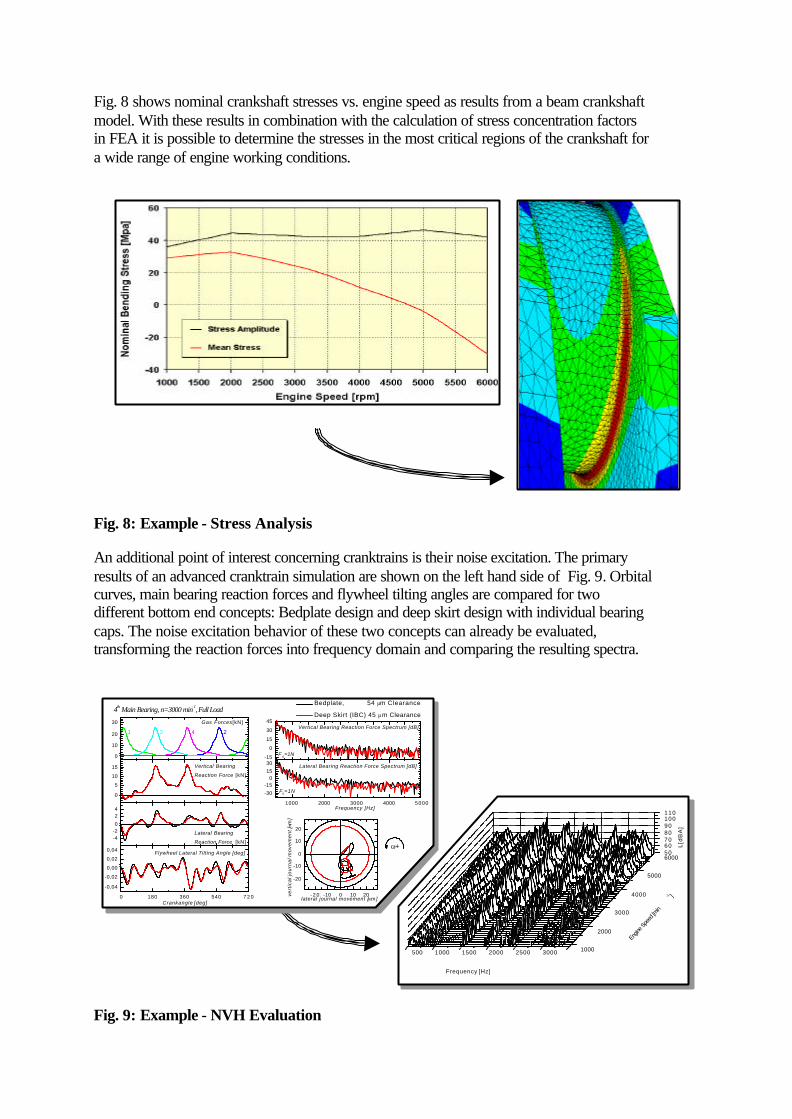
Fig. 8 shows nominal crankshaft stresses vs. engine speed as results from a beam crankshaft model. With these results in combination with the calculation of stress concentration factors in FEA it is possible to determine the stresses in the most critical regions of the crankshaft for a wide range of engine working conditions.
Fig. 8: Example - Stress Analysis
An additional point of interest concerning cranktrains is their noise excitation. The primary results of an advanced cranktrain simulation are shown on the left hand side of Fig. 9. Orbital curves, main bearing reaction forces and flywheel tilting angles are compared for two different bottom end concepts: Bedplate design and deep skirt design with individual bearing caps. The noise excitation behavior of these two concepts can already be evaluated, transforming the reaction forces into frequency domain and comparing the resulting spectra.
500 1000 1500 2000 2500 3000
5060708090100110
6000
5000
4000
3000
2000
1000
Frequency [Hz]
Engin
e Spe
ed [m
in-1 ]
L[d
BA
]
0 180 360 540 7 2 0
-0,04
-0,02
0,00
0,02
0,04
Frequency [Hz]
vert
ica
l jo
urn
al m
ove
me
nt [
µm]
lateral journal movement [µm]
Flywheel Lateral Tilting Angle [deg]
Crankangle [deg]
4th Main Bearing, n=3000 min- 1, Full Load
-4-20
24
Lateral Bearing
Reaction Force [kN]
0
10
20
30
Lateral Bearing Reaction Force Spectrum [dB]
Vertical Bearing Reaction Force Spectrum [dB]
Vertical Bearing
Reaction Force [kN]
2431
Gas Forces [kN]
- 2 0 -10 0 10 20
-20
-10
0
10
20
ω+
Bedplate, 54 µm Clearance
Deep Skirt (IBC) 45 µm Clearance
-15
0
15
30
45
F0=1N
0
5
10
15
1000 2000 3000 4000 5000
-30
-150
15
30
F0=1N
Fig. 9: Example - NVH Evaluation
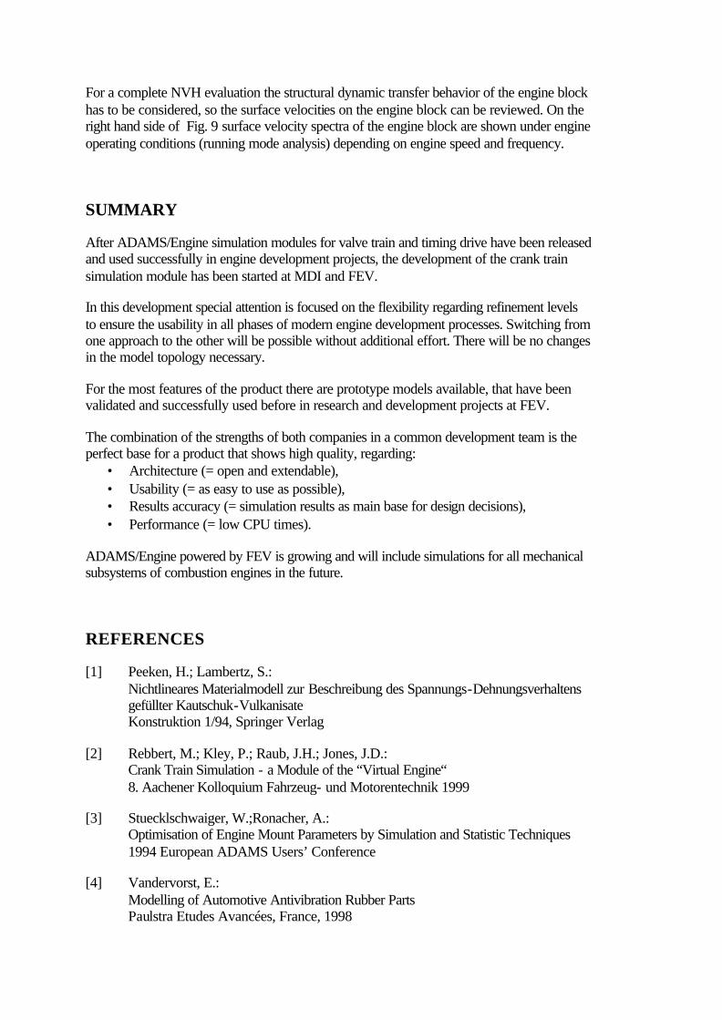
For a complete NVH evaluation the structural dynamic transfer behavior of the engine block has to be considered, so the surface velocities on the engine block can be reviewed. On the right hand side of Fig. 9 surface velocity spectra of the engine block are shown under engine operating conditions (running mode analysis) depending on engine speed and frequency.
SUMMARY
After ADAMS/Engine simulation modules for valve train and timing drive have been released and used successfully in engine development projects, the development of the crank train simulation module has been started at MDI and FEV.
In this development special attention is focused on the flexibility regarding refinement levels to ensure the usability in all phases of modern engine development processes. Switching from one approach to the other will be possible without additional effort. There will be no changes in the model topology necessary.
For the most features of the product there are prototype models available, that have been validated and successfully used before in research and development projects at FEV.
The combination of the strengths of both companies in a common development team is the perfect base for a product that shows high quality, regarding:
• Architecture (= open and extendable), • Usability (= as easy to use as possible), • Results accuracy (= simulation results as main base for design decisions), • Performance (= low CPU times).
ADAMS/Engine powered by FEV is growing and will include simulations for all mechanical subsystems of combustion engines in the future.
REFERENCES
[1] Peeken, H.; Lambertz, S.: Nichtlineares Materialmodell zur Beschreibung des Spannungs-Dehnungsverhaltens gefüllter Kautschuk-Vulkanisate Konstruktion 1/94, Springer Verlag
[2] Rebbert, M.; Kley, P.; Raub, J.H.; Jones, J.D.: Crank Train Simulation - a Module of the “Virtual Engine“ 8. Aachener Kolloquium Fahrzeug- und Motorentechnik 1999
[3] Stuecklschwaiger, W.;Ronacher, A.: Optimisation of Engine Mount Parameters by Simulation and Statistic Techniques 1994 European ADAMS Users’ Conference
[4] Vandervorst, E.: Modelling of Automotive Antivibration Rubber Parts Paulstra Etudes Avancées, France, 1998

11/28/00 - Rebbert 1
ADAMS/ Enginepowered by
Powertrain Dynamics ApplicationsPart II: Cranktrain Dynamics
11/28/00 - Rebbert 1
Powertrain Dynamics Applications usingADAMS/Engine powered by FEV
Part II: Cranktrain Dynamics
Martin RebbertPhilipp Kley
FEV Motorentechnik GmbH
International ADAMS Users Conference, RomeNovember 16th , 2000
11/28/00 - Rebbert 2
ADAMS/ Enginepowered by
Powertrain Dynamics ApplicationsPart II: Cranktrain Dynamics
Intake GasDynamics
Intake GasDynamics
Exhaust GasDynamics
Exhaust GasDynamics
Combustion Combustion
CranktrainCranktrain
Valve TrainValve Train
Timing DriveTiming Drive
AccessoriesAccessories
AccessoryDrive
AccessoryDrive
Piston /Piston Ring
Piston /Piston Ring
Engine CAE Areas

11/28/00 - Rebbert 3
ADAMS/ Enginepowered by
Powertrain Dynamics ApplicationsPart II: Cranktrain Dynamics
EngineeringJudgment Tools 3D CAE
Engine Development CAE - Support
Prototyping
Detail Design
Layout
Concept
Refinement Level
CAE Support in Development Processes
11/28/00 - Rebbert 4
ADAMS/ Enginepowered by
Powertrain Dynamics ApplicationsPart II: Cranktrain DynamicsRefinement Levels at Cranktrain SimulationLevel 1: Rigid Crankshaft
Part: Throw Part: Throw
Joint: Fixed Part: Dummy(no Geometry,no Inertia)
Joint:Universal
Coincident (=no distance)
Level 2: Torsion Flexible CrankshaftJoint: Revolute+ Force: RSPD
Joint:Universal
Part: Throw Part: Throw
Part: Dummy(no Geometry, no Inertia)
Coincident(=no distance)
Level 4: FEA Flexible Crankshaft
Level 3: Beam Flexible Crankshaft
Part(geometrybased)
Marker
Beam
RefinementLevel
RefinementLevel

11/28/00 - Rebbert 5
ADAMS/ Enginepowered by
Powertrain Dynamics ApplicationsPart II: Cranktrain DynamicsParametric Description of Cranktrain Geometry
bank_angle
crank_offset
CylinderReference
Crank PinPosition
PistonPosition &Orientation
Generic Parametrics forn Cylinders on m BanksUsing Construction Frames
Open Architecture usingCranktrain Templates
11/28/00 - Rebbert 6
ADAMS/ Enginepowered by
Powertrain Dynamics ApplicationsPart II: Cranktrain DynamicsHydrodynamic Plain Bearings
HD ReactionForce DatabaseHD Reaction
Force Database
3-dimensionalSolution of
Reynolds Equation
3-dimensionalSolution of
Reynolds Equation
ADAMS/SOLVERSUBROUTINES
ADAMS/SOLVERSUBROUTINES Read States
Access Database
Apply Force

11/28/00 - Rebbert 7
ADAMS/ Enginepowered by
Powertrain Dynamics ApplicationsPart II: Cranktrain DynamicsEngine Mounts
K0
K4K3K2
C4C3C2
Rubber Mount Model
K0
K4K3K2
C4C3C2
K2HC2H
C3H
s0Gap
mH
Hydro Mount Model
• Displacement dependency included using nonlinear expressions
• Frequency dependency included using linear transfer functions
11/28/00 - Rebbert 8
ADAMS/ Enginepowered by
Powertrain Dynamics ApplicationsPart II: Cranktrain DynamicsExample:
AdvancedCranktrainSimulation

11/28/00 - Rebbert 9
ADAMS/ Enginepowered by
Powertrain Dynamics ApplicationsPart II: Cranktrain DynamicsExample: Stress Analysis
11/28/00 - Rebbert 10
ADAMS/ Enginepowered by
Powertrain Dynamics ApplicationsPart II: Cranktrain DynamicsExample: NVH Evaluation
500 1000 1500 2000 2500 3000
5060708090100110
6000
5000
4000
3000
2000
1000
Frequency [Hz]
Engine Speed [m
in-1 ]
L[dB
A]
0 180 360 540 720
-0,04
-0,02
0,00
0,02
0,04
Frequency [Hz]
vert
ical
jour
nal m
ovem
ent [
µm]
lateral journal movement [µm]
Flywheel Lateral Tilting Angle [deg]
Crankangle [deg]
4th Main Bearing, n=3000 min-1, Full Load
-4-2024
Lateral Bearing
Reaction Force [kN]
0
10
20
30
Lateral Bearing Reaction Force Spectrum [dB]
Vertical Bearing Reaction Force Spectrum [dB]
Vertical Bearing
Reaction Force [kN]
2431Gas Forces [kN]
-20 -10 0 10 20
-20
-10
0
10
20
ω+
Bedplate, 54 µm Clearance
Deep Skirt (IBC) 45 µm Clearance
-15
0
15
3045
F0=1N
0
5
10
15
1000 2000 3000 4000 5000
-30-15
01530
F0=1N

11/28/00 - Rebbert 11
ADAMS/ Enginepowered by
Powertrain Dynamics ApplicationsPart II: Cranktrain DynamicsSummary
• ADAMS/Engine powered by FEV will include simulation methods for all mechanical subsystems in the future.
• Joined development is a perfect base for a high quality product, regarding:- Open and extendable Architecture- Usability- Results Accuracy- Performance
• Most techniques have already been used and are validated
• Special attention is focused on maximum flexibility regarding refinement levels
• Development of Cranktrain Simulation Module has been started in close cooperation between MDI and FEV