abril 2009 programing
TRANSCRIPT
8/10/2019 Abril 2009 Programing
http://slidepdf.com/reader/full/abril-2009-programing 1/8
March/April 2009 Volume 16, No. 2 (TS-PU-0007-09)
IN THIS ISSUE
Programming Tips and Tools . . . . . . . .Buyer Beware: Counterfeit Tools . . . .
New ACDelco Advanced CoolingSystem Diagnosis Seminar . . . . . . . . .
Checking Coolant Hoses . . . . . . . . . .
2009 TSS Scholarship DeadlineApproaching . . . . . . . . . . . . . . . . . . . . .
ASE Testing . . . . . . . . . . . . . . . . . . . . .
Controlling Diesel Emissions . . . . . . .
Tech Tips . . . . . . . . . . . . . . . . . . . . . . . .
Training Update . . . . . . . . . . . . . . . . . .
Show Off Your Ride . . . . . . . . . . . . . .
– www.acdelcotechconnect.com, click on the TechConnect Magazine link, or
– Log on to the ACDelco LMS, click on thResources link
ON THE WEB
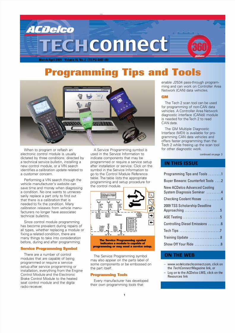
When to program or reflash an electronic control module is usually dictated by three conditions: directed bya technical service bulletin, installing anew control module, or a VIN searchidentifies a calibration update related to
a customer concern.Performing a VIN search through the
vehicle manufacturer’s website cansave time and money when diagnosinga condition. No one wants to unneces-sarily replace a part only to find outthat there is a calibration that isneeded to fix the condition. Many calibration releases from vehicle manu-facturers no longer have associatedtechnical bulletins.
Since control module programminghas become prevalent during repairs ofall types, whether replacing a module orfixing a related condition, there aremany things to take into considerationbefore, during and after programming.
Service Programming SymbolThere are a number of control
modules that are capable of being programmed or require a servicesetup after service programming orinstallation, everything from the EngineControl Module and the ElectronicBrake Control Module to the heatedseat control module and the digitalradio receiver.
A Service Programming symbol isused in the Service Information to indicate components that may be programmed or require a service setupafter installation or service. Click on thesymbol in the Service Information to
go to the Control Module Referencetable. The table lists the appropriate programming and setup procedure forthe control module.
The Service Programming symbolmay also appear on the parts label ofsome components or be embossed onthe part itself.
Programming ToolsEvery manufacturer has developed
their own programming tools that
1
enable J2534 pass-through program-ming and can work on Controller AreaNetwork (CAN) data vehicles.
GMThe Tech 2 scan tool can be used
for programming of non-CAN datavehicles. A Controller Area Networkdiagnostic interface (CANdi) moduleis needed for the Tech 2 to readCAN data.
The GM Multiple DiagnosticInterface (MDI) is available for pro-gramming CAN data vehicles andoffers faster programming than theTech 2 while freeing up the scan toolfor other diagnostic work.
continued on page
Programming Tips and Tools
The Service Programming symbolindicates a module is capable of
programming or may need a service setup.

8/10/2019 Abril 2009 Programing
http://slidepdf.com/reader/full/abril-2009-programing 2/8
ACDelco TechConnect is published bi-monthlyand online for technicians of Total ServiceSupport (TSS) and Key Fleet accounts toprovide timely service information, increaseknowledge and improve the performance of the service center.
Publisher:Mike DeSander
ACDelcoE-mail
Editor:Mike Militello
ACDelcoE-mail
Technical Editors:Mark Spencer
Jim HornerE-mail
Production Manager:Marie Meredith
Desktop Publishing:5by5 Design
Write to:
ACDelco TechConnectP.O. Box 500Troy, MI 48007-0500
On the Web:To read and search recent issues ofTechConnect online: – www.acdelcotechconnect.com,
click on the TechConnect Magazinelink, or
– Log on to the ACDelco LMS, clickon the Resources link
ACDelco service tips are intended for use by professional t echnicians, not a “do-it-yourselfer.”They are written to inform those technicians of con-
ditions that may occur on some vehicles, or to pro-vide information that could assist in the proper ser-vice of a vehicle. Properly trained technicians havethe equipment, tools, safety instructions and know-how to do a job properly and safely. If a condition isdescribed, it cannot be assumed that the informa-tion applies to all vehicles or that all vehicles willhave that condition.
All materials and programs described in this magazine are subject to change. Submission ofmaterials implies the right to edit and publish.Inclusion in the publication is not necessarily anendorsement of the individual or the company.TechConnect is published for ACDelco by SandyCorporation, Troy, MI.
©2009 ACDelco. All rights reserved.
2
Buyer Beware:Counterfeit Tools
Whatever you want, chancesare you can find it on the web.But one of the chances you takewhen buying items through anonline sale or an auction websiteis if they’re the real thing
or fakes.GM and Bosch Diagnostics
have discovered counterfeit Tech2 scan tools and GM ControllerArea Network diagnostic inter-face (CANdi) modules availableto the aftermarket through onlineauction websites and other retailwebsites.
These tools appear to be veryauthentic from their exteriorappearance. Everything is copiedto closely resemble the real thing – fromthe cables and plastic cases to the brandlogos and serial numbers. However,some of these counterfeit tools acquiredby GM and Bosch Diagnostics have beenfound to be built with lower grade com-ponents and electronics or with usedequipment from other diagnostic tools.As a result, some of the counterfeit toolswill not work right from the start, mayfail quickly or will run extremely slow.
In some cases, there are someslight physical clues that identify a counterfeit tool. Some fake CANdi modules have the same serial numberon each module. Real CANdi moduleswill have a different serial moduleon each one.
The LED on the top of a counterfeitCANdi module may be green. RealCANdi modules have a clear LED thatglows green.
Another clue on counterfeit modulesmay be the lack of a printed identifier number on the cable. Plus, the cable connectors of some counterfeit modules have brass inserts. The realmodules use aluminum inserts.
Scan tools and diagnostic tools suchas the Tech 2 and CANdi module arelarge investments for many service centers. For buyers to ensure that theyare getting the real tool, and the techsupport and warranty protection (authen-tic Tech 2 scan tools and CANdi modulesinclude a two-year warranty) that comeswith it, purchases should be made from a well known sourcesuch as Bosch Diagnostics or OTC Tools.
The bottom line may be that if the online deal for diagnostic and scan toolsseems too good to be true, it probably is.– Thanks to Bob Stewart and Mike Waszczenko
Can you tell the difference?The top CANdi module is counterfeit.
An authentic CANdi module hasa clear LED that glows green (A),
not a green LED (B).
An authentic CANdi module usesaluminum inserts on the cable (A),
not brass (B).

8/10/2019 Abril 2009 Programing
http://slidepdf.com/reader/full/abril-2009-programing 3/83
ChryslerThe DRBIII supports vehicle programming but does not
work on CAN data vehicles.
The StarSCAN works on Chrysler’s CAN data vehicles. TheStarMOBILE adds wireless support, a custom data recorder,and pass-through diagnostics, freeing up the StarSCAN formore extensive diagnostic tasks.
FordThe New Generation Star (NGS) Tester combined with
the NGS Web Flash Kit provides the ability to download Fordcalibration files and reprogram modules.
Integrated Diagnostic Software and the VehicleCommunication Module are used to interface with standardcomputer platforms (PCs, laptops) on CAN data vehicles.
ToyotaThe Mastertech scan tool can be used on non-CAN data
vehicles.
The TIS techstream offers full support and reprogrammingfor current CAN data Toyota/Scion/Lexus vehicles.
For more information about scan tools and other program-ming tools available from vehicle manufacturers, refer to thefollowing websites.
Reputable aftermarket tool manufacturers, such asEASE Diagnostics, Snap-On Tools, SPX/OTC, and Bosch/ Vetronix, also offer various scan tools and pass-through programming tools.
Proper ProgrammingBefore programming a control module, there are several
important practices to follow to ensure that successful programming occurs.
Vehicle system voltage – Thevehicle’s battery voltage should begreater than 12 volts but less than16 volts. The battery should becharged before a programmingevent. A battery charger shouldNOT be connected to the battery during programming unless it is aMidtronics PSC charger validatedfor use during programming.
Also turn off or disable any sys-
tem or accessories that may put aload on the battery, such as enginecooling fans, the radio, DaytimeRunning Lamps, etc.
Ignition switch – The ignition switch must be in the Onposition. Do not begin programming right away. It’s critical towait until all modules on the vehicle have “awakened” beforebeginning. A good rule of thumb is to not plug in any toolsuntil the instrument panel lights and tones stop after theinitial key-on.
Do not change the position of the ignition switch during programming unless instructed to do so, such as after a successful programming. Do not turn off the ignition switch ifthe programming procedure is interrupted or is unsuccessful.Attempt to reprogram the control module.
Connections – Make sure all tool connections are secure.Do not disturb the tool harness while programming. If aninterruption occurs during programming, a programming failure or control module damage may occur.
After programming, check for the success of the programming by:
1. Turning off the vehicle ignition for 30 seconds to allowthe module to power down and reset.
2. Start the engine.
3. Check for Diagnostic Trouble Codes (DTCs) in all modules.
In addition to following the proper programming procedures,successful programming also depends on a few other key factors. These include:
• High-speed Internet access in the shop
• A high-quality J2534 pass-through tool
• A subscription to the manufacturer’s website
• Carefully reading all directions before and during thedownloading of the flash files or programming of the control module
• Performing any necessary vehicle setup after program-ming. Refer to the appropriate Service Information
– Thanks to Mike Militello
Programming Tips and Tools -continued from page 1
Audi www.equipmentsolutions.com
BMW www.centrallettershop.com
Chrysler(Chrysler/Dodge/Jeep) www.techauthority.com
Ford(Ford/Lincoln/Mercury) www.motorcraft.com
GM(Buick/Cadillac/Chevrolet/ GMC/HUMMER/ Oldsmobile/Saturn)
www.acdelcotechconnect.com
Honda(Honda/Acura) www.serviceexpress.honda.com
Hyundai www.dealerequipment.com
Kia www.kiatechinfo.com
Mazda www.mazdatechinfo.com
Mercedes-Benz www.startekinfo.com
Mitsubishi www.mitsubishitechinfo.com
Nissan(Nissan/Infiniti) www.nissantechinfo.com
Porsche www.techinfo.porsche.com
Saab www.saabtechinfo.com
Subaru www.techinfo.subaru.com
Toyota(Toyota/Lexus/Scion)
www.techinfo.toyota.com
Volkswagen erwin.volkswagen.com
Volvo www.volvotechinfo.com
Maintain battery voltageduring programming.
8/10/2019 Abril 2009 Programing
http://slidepdf.com/reader/full/abril-2009-programing 4/84
New ACDelco Advanced Cooling SystemDiagnosis Seminar
It’s the major cause of mechanical breakdown on thehighway according to the U.S. Department of Transportation –the failure of the cooling system. However, many vehicle owners ignore routine check-ups and regular cooling systemmaintenance. Recent national car care clinics revealed thatone out of every five vehicles have a low, leaking or dirty
coolant condition.The proper operation of the cooling system is critical in
modern computer-controlled engines to meet emissions, fueleconomy and other performance standards. Plus, the vehicle’sA/C system adds to the load on the cooling system.
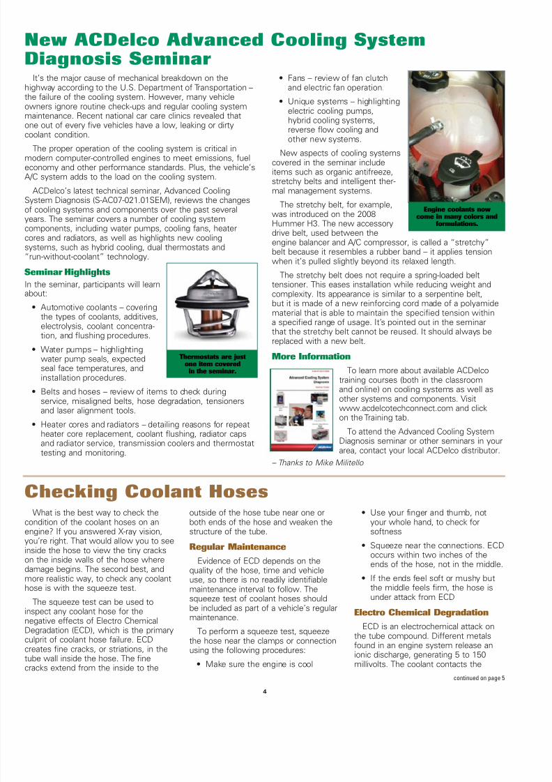
ACDelco’s latest technical seminar, Advanced CoolingSystem Diagnosis (S-AC07-021.01SEM), reviews the changesof cooling systems and components over the past severalyears. The seminar covers a number of cooling system components, including water pumps, cooling fans, heatercores and radiators, as well as highlights new cooling systems, such as hybrid cooling, dual thermostats and“run-without-coolant” technology.
Seminar HighlightsIn the seminar, participants will learnabout:
• Automotive coolants – coveringthe types of coolants, additives,electrolysis, coolant concentra-tion, and flushing procedures.
• Water pumps – highlightingwater pump seals, expectedseal face temperatures, andinstallation procedures.
• Belts and hoses – review of items to check during service, misaligned belts, hose degradation, tensioners
and laser alignment tools.• Heater cores and radiators – detailing reasons for repeat
heater core replacement, coolant flushing, radiator capsand radiator service, transmission coolers and thermostattesting and monitoring.
• Fans – review of fan clutchand electric fan operation.
• Unique systems – highlightingelectric cooling pumps,hybrid cooling systems,reverse flow cooling andother new systems.
New aspects of cooling systemscovered in the seminar includeitems such as organic antifreeze,stretchy belts and intelligent ther-mal management systems.
The stretchy belt, for example,was introduced on the 2008Hummer H3. The new accessorydrive belt, used between theengine balancer and A/C compressor, is called a “stretchy”belt because it resembles a rubber band – it applies tensionwhen it’s pulled slightly beyond its relaxed length.
The stretchy belt does not require a spring-loaded belt tensioner. This eases installation while reducing weight andcomplexity. Its appearance is similar to a serpentine belt,but it is made of a new reinforcing cord made of a polyamidematerial that is able to maintain the specified tension withina specified range of usage. It’s pointed out in the seminarthat the stretchy belt cannot be reused. It should always bereplaced with a new belt.
More InformationTo learn more about available ACDelco
training courses (both in the classroomand online) on cooling systems as well asother systems and components. Visit
www.acdelcotechconnect.com and clickon the Training tab.
To attend the Advanced Cooling SystemDiagnosis seminar or other seminars in yourarea, contact your local ACDelco distributor.
– Thanks to Mike Militello
Thermostats are justone item covered
in the seminar.
Engine coolants nowcome in many colors and
formulations.
Checking Coolant HosesWhat is the best way to check the
condition of the coolant hoses on anengine? If you answered X-ray vision,you’re right. That would allow you to seeinside the hose to view the tiny crackson the inside walls of the hose wheredamage begins. The second best, andmore realistic way, to check any coolanthose is with the squeeze test.
The squeeze test can be used toinspect any coolant hose for the negative effects of Electro ChemicalDegradation (ECD), which is the primaryculprit of coolant hose failure. ECD creates fine cracks, or striations, in thetube wall inside the hose. The finecracks extend from the inside to the
outside of the hose tube near one orboth ends of the hose and weaken thestructure of the tube.
Regular MaintenanceEvidence of ECD depends on the
quality of the hose, time and vehicleuse, so there is no readily identifiablemaintenance interval to follow. Thesqueeze test of coolant hoses shouldbe included as part of a vehicle’s regularmaintenance.
To perform a squeeze test, squeezethe hose near the clamps or connectionusing the following procedures:
• Make sure the engine is cool
• Use your finger and thumb, notyour whole hand, to check for softness
• Squeeze near the connections. ECDoccurs within two inches of theends of the hose, not in the middle.
• If the ends feel soft or mushy butthe middle feels firm, the hose isunder attack from ECD
Electro Chemical DegradationECD is an electrochemical attack on
the tube compound. Different metalsfound in an engine system release anionic discharge, generating 5 to 150 millivolts. The coolant contacts the
continued on page 5
8/10/2019 Abril 2009 Programing
http://slidepdf.com/reader/full/abril-2009-programing 5/85
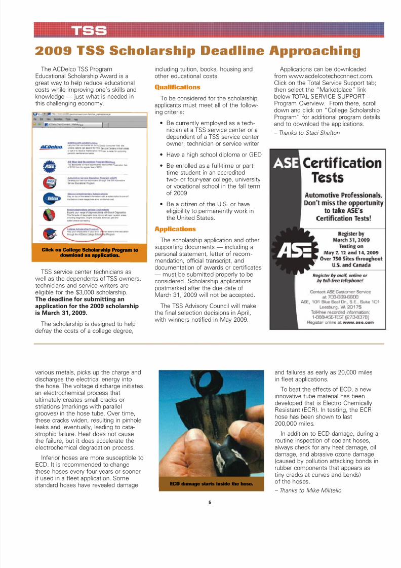
various metals, picks up the charge anddischarges the electrical energy intothe hose. The voltage discharge initiatesan electrochemical process that ultimately creates small cracks or striations (markings with parallelgrooves) in the hose tube. Over time,these cracks widen, resulting in pinholeleaks and, eventually, leading to cata-strophic failure. Heat does not causethe failure, but it does accelerate theelectro chemical degradation process.
Inferior hoses are more susceptible toECD. It is recommended to changethese hoses every four years or soonerif used in a fleet application. Some standard hoses have revealed damage
and failures as early as 20,000 milesin fleet applications.
To beat the effects of ECD, a new
innovative tube material has been developed that is Electro ChemicallyResistant (ECR). In testing, the ECRhose has been shown to last200,000 miles.
In addition to ECD damage, during aroutine inspection of coolant hoses,always check for any heat damage, oildamage, and abrasive ozone damage(caused by pollution attacking bonds inrubber components that appears astiny cracks at curves and bends)of the hoses.– Thanks to Mike Militello
ECD damage starts inside the hose.
2009 TSS Scholarship Deadline ApproachingThe ACDelco TSS Program
Educational Scholarship Award is agreat way to help reduce educationalcosts while improving one’s skills and
knowledge — just what is needed inthis challenging economy.
TSS service center technicians aswell as the dependents of TSS owners,technicians and service writers are eligible for the $3,000 scholarship.The deadline for submitting an application for the 2009 scholarshipis March 31, 2009.
The scholarship is designed to helpdefray the costs of a college degree,
including tuition, books, housing andother educational costs.
Qualifications
To be considered for the scholarship,applicants must meet all of the follow-ing criteria:
• Be currently employed as a tech -nician at a TSS service center or adependent of a TSS service centerowner, technician or service writer
• Have a high school diploma or GED
• Be enrolled as a full-time or part-time student in an accreditedtwo- or four-year college, universityor vocational school in the fall termof 2009
• Be a citizen of the U.S. or have eligibility to permanently work inthe United States.
Applications
The scholarship application and othersupporting documents — including a personal statement, letter of recom -mendation, official transcript, and documentation of awards or certificates
— must be submitted properly to beconsidered. Scholarship applicationspostmarked after the due date ofMarch 31, 2009 will not be accepted.
The TSS Advisory Council will makethe final selection decisions in April,with winners notified in May 2009.
Applications can be downloadedfrom www.acdelcotechconnect.com.Click on the Total Service Support tab;then select the “Marketplace” link
below TOTAL SERVICE SUPPORT –Program Overview. From there, scrolldown and click on “College ScholarshipProgram” for additional program detailsand to download the applications.– Thanks to Staci Shelton
Click o n Col lege S cholar ship P rogra m todown load a n app licatio n.

8/10/2019 Abril 2009 Programing
http://slidepdf.com/reader/full/abril-2009-programing 6/86
Controlling Diesel EmissionsThe latest U.S. EPA diesel emission regulations were
designed to combat diesel pollution and obtain gasoline-likeemissions standards from diesel-powered vehicles.
To achieve these goals, all diesel engines produced since2007 must meet a reduction of nitrogen oxide (NOx) andhydrocarbons (HC) by 50% and particulate matter by 90+%over earlier 2004 emission standards.
In addition, Ultra-Low Sulfur Diesel (ULSD) fuel must havea 97% reduction in the sulfur content of highway diesel fuel.According to the EPA, some studies show that the use ofULSD alone can reduce particulate matter emissions bybetween 10-20%. However, of greater significance is thatthis cleaner fuel enables the use of advanced after-treatmenttechnologies on new engines.
Emissions Control TechnologiesSome of the emissions control technologies of the Duramax
6.6L diesel engine in Chevrolet and GMC light-duty trucks andvans and medium-duty trucks include a Diesel OxidationCatalyst (DOC) and a Diesel Exhaust Particulate Filter (DPF).
The DOC reduces hydrocarbons and oxides of nitrogen, carbon monoxide and odor-causing compounds. It also turnsthe majority of emissions into water and oxygen.
The DPF traps the particulate matter (solid particles thatappear as black smoke) from the engine exhaust before theycan be emitted into the atmosphere.
The DOC and DPFare installed in theexhaust system.To prevent clogging,particulate matter inthe DPF is periodicallyburned off, leavingash and yielding carbon dioxide andwater. This processis called particulate filter regeneration.
DPF RegenerationDPF regeneration
may occur under several circumstances, called Active Regeneration, PassiveRegeneration and Service Regeneration.
Active Regeneration – The regeneration operation is controlled by the engine control module (ECM), which keepstrack of the mileage driven, the amount of fuel consumed, thehours of operation and the exhaust differential pressure.
When the conditions are met for regeneration to occur,the ECM enters a different engine calibration strategy thatincludes additional fuel injection pulses. This heats the DOCabove its normal operating temperature and regenerationbegins. For the process to complete satisfactorily and efficiently clean the filter, the vehicle must be operated continuously for approximately 18 minutes at speeds greaterthan 30 mph (50 km/h). If the engine is allowed to return toidle during this time, the idle speed may be elevated slightlyand the operating sound may be different. This is normal, andthe driver doesn’t need to do anything.
During regeneration, the exhaust temperature increases(greater than 500° C), which converts the particulates intoharmless gases and ash. The DPF is then clean and ready tofilter particulates again.
If normal driving doesnot provide
the necessaryconditions forregenerationto occur, thepressure differentialcontinues toincreaseacross theexhaust filter.On some vehi-cles, a CleanExhaust Filtermessage willbe displayed or a warning lamp will illuminate.
If the conditions necessary for regeneration do not takeplace, however, the ECM will eventually illuminate the MILand the Reduced Power warning lamp. The engine enters theReduced Power mode, which will require the vehicle to beserviced.
Passive Regeneration – Passive regeneration occurs whenexhaust gas temperature is elevated above 300°C (575° F).These temperatures may be reached when the engine isunder heavy load.
Service Regeneration – Service regeneration is performedwith the scan tool and is used to clean a soot-loaded filterduring a service visit.
Regeneration TemperaturesThe exhaust system has been designed to deal with the
temperatures involved in the regeneration process. On longwheelbase models, for instance, a heat shield protects therear axle shock absorbers. All models have an exhaust coolerat the end of the tailpipe. A vacuum created by the exhaustpassing through the openings draws in cool air, which mixeswith the exhaust gases.
There are times when a DPF service regenerationmust be performed in the service center. This must beconducted outdoors. The shop exhaust system will not handle the heat.
Diesel Fuel and Oil RequirementsThe Duramax 6.6L diesel engine requires Ultra-Low
Sulfur Diesel, which limits sulfur content to 15 ppm (partsper million).
It also requires oil that conforms to the CJ-4 standard established by the American Petroleum Institute. This oiloffers lower oil consumption and reduces limits for phospho-rus, sulfur and ash. Low ash oil is needed to extend the life ofthe DPF as well as to reduce the formation of engine sludgeand deposits.– Thanks to Frank Tornambe
DOC and DPF position on theexhaust system
A message or warning lamp will indicate whenregeneration is required.

8/10/2019 Abril 2009 Programing
http://slidepdf.com/reader/full/abril-2009-programing 7/87
Wheel SpacersOriginal equipment (OEM) wheels
and GM accessory wheels aredesigned to mount directly to the vehicle's wheel hubs without need forspacers (adapters). Some aftermarketwheels are manufactured to fit a limit-ed number of wheel hub diameters andrely on spacers to accommodate thedifferences.
In some instances,owners have installedaftermarket wheelsthat require the useof spacers and laterswitched back to the
OEM wheels. If thespacer is not removedfrom the wheel hub,it will interfere withthe proper fit of theOEM wheel. The spacer can affectwheel nut torque, causing looseningand possible wheel detachment. Othereffects include wobbling, vibration andunnatural tire wear.
If a vehicle displays such characteris-tics, and has previously been fitted withaftermarket wheels, check for wheelhub spacers and remove them if they
are present.
No, Hard or Slow Start,Backfire duringCrank/Start
1999-2000 Cadillac Escalade;1995-2000 Chevrolet and GMC S/Tmodels; 1996-2000 Chevrolet and GMCC/K, M/L, G, P models; 1996-2000Oldsmobile Bravada — with the 4.3L,5.0L, 5.7L or 7.4L engine (RPOs L35,LF6, L30, L31, L29)
One of the following conditions may
exist: backfire or kickback duringcrank/start, no start, slow or hardcrank/start, grinding or unusual noisesduring crank/start, cracked or brokenengine block at the starter boss, brokenstarter drive housing, or broken starterring gear on flywheel.
A condition may exist that allows thecrankshaft position sensor to commandup to 50 extra degrees of sparkadvance during engine cranking only.This in turn exposes the engine to high-er than normal cylinder pressures thatmay result in an inoperative condition
to the starter drive housing, the engineflywheel starter ring gear, or the engineblock at the outside edge of thestarter boss.
Check for a powertrain DTC P0338.This DTC will not illuminate the CheckEngine light. If this code is stored, thecrankshaft position sensor must bereplaced and the other components —engine block at the starter boss,starter drive housing, and engine fly-wheel starter ring gear — inspectedfor damage.
Some flywheel wear is normal.Look for broken or missing teethand/or cracks.
Refer to GM bulletin 00-06-04-014 formore information.
Starter Failure, BindingIgnition, Starter StayingEngaged
1999-2003 Ford Excursion andF-Series Super Duty
The starter may stay engagedafter releasing the key from the startposition or the ignition lock cylindermay be sticking/binding, which mayresult in starter failure
These conditions may be due to theignition lock cylinder binding and notfully returning from the start position tothe run position, a short condition onstarter relay circuit 113 or 1093, a stick-ing starter relay, or an internal short inthe power distribution junction box.
If one of these conditions occurs,inspect the starter and flywheel fordamage and replace as necessary.Inspect the starter circuit for shorts,including the Power DistributionJunction Box, and verify proper cylinderlock function; service as necessary.
Noise from Rear of Vehicleduring Cold Start
2004-2008 Chevrolet Aveo;2006-2008 Chevrolet Cobalt, HHR;2007-2008 Pontiac G5; 2006-2007Saturn ION
Shortly after cold starting the engine,three to five brief knock noises may beheard from the rear of the vehicle. Thesound is similar to someone tapping onthe rear window. The may be the result
of the EVAP vent valve going through anormal diagnostic cleaning cycle.
If this condition is experienced andthe noise is isolated to the EVAP ventvalve, inspect the vent valve pipe toensure that it is routed properly and notgrounding out. If the pipe is routedproperly, this noise should be consid-ered a normal characteristic.
No Crank, StarterTerminal Fatigue
1997-2007 Ford Crown Victoria,1997-2004 Ford F-150 Heritage,1997-2006 Ford Expedition, 1998-2006E-Series, 1999-2006 Ford F-Series
Super Duty, 2002-2007 Ford Explorer,2004-2006 Ford F-150, 2007 FordExplorer Sport Trac; 1998-2006 LincolnNavigator, 2003-2005 Lincoln Aviator;1997-2007 Mercury Grand Marquis,2002-2007 Mercury Mountaineer
Some vehicles may exhibit a no crankcondition due to an open circuit in thestarter relay to starter motor circuit atthe starter motor connection.
Follow the appropriate ServiceInformation to correct the condition.A starter terminal pigtail kit is availableto eliminate the need to replace theentire harness for the terminal connec-tion. The terminal kit only services thestarter relay to starter motor circuit.It does not service the starter motorbattery power circuit.
The following technical tips provide repair information about specific conditions on a variety of vehicles. If you have a tough or unusual service repair, the TSS Technical Assistance Hot Line can help. Call 1-800-825-5886, prompt #2 , to speak with a technicaexpert with the latest OEM information.
Diagnostic AssistanceFor free technical diagnostic
assistance and product informationregarding specific ACDelco products,contact these toll-free informationhotlines staffed by ASE-certifiedtechnicians:
Brakes – 1-888-701-6169 (prompt #1)
Chassis – 1-888-701-6169 (prompt #2)
Clutches – 1-888-725-8625
Lift Supports – 1-800-790-5438
Shocks – 1-877-466-7752
Starters and Alternators –1-800-228-9672
Steering – 1-866-833-5567
Wiper Blades – 1-800-810-7096
Typical wheelspacer

8/10/2019 Abril 2009 Programing
http://slidepdf.com/reader/full/abril-2009-programing 8/88TS-PU-0007-09
Current Instructor-Led TrainingACDelco’s Instructor-Led Training (ILT) courses provide hands-on instruction
on the latest automotive systems. The following ILT courses are currentlybeing held at training center locations around the country.
How to Take ACDelco TrainingGo to www.acdelcotechconnect.com and click on the Training tab to log onto the ACDelco Learning Management System (LMS).
• To enroll in an Instructor-Led Training (ILT) course, click on the Enrollmentlink or the Instructor-Led Courses link.
• To launch a Web-Based Training (WBT) course, click on theWeb-Based Courses link to view the catalog and select a specific course.
• To launch a TechAssist (TAS) course, click on the TechAssists link to viewthe catalog and select a specific course.
• To launch a Simulation (SIM) , click on the Simulations link to view the catalog and select a diagnostic challenge simulation.
Course Number Course Name
S-AC07-02.01ILT Automotive Air Conditioning: Advanced RefrigerantSystem Diagnostics
S-AC07-03.01ILT HVAC Control System Operation and Diagnostics
S-AC07-06.01ILT Toyota HVAC
S-BK05-01.01ILT Braking Systems
S-EL06-04.01ILT Body Control Systems Diagnostics
S-EL06-10.01ILT Battery, Charging, & Starting
S-EL06-11.01ILT Automotive Electrical Circuit Diagnosis and Repair
S-EP08-02.01ILT Engine Performance: Computer Controls and IgnitionSystem Diagnostics
S-EP08-03.01ILT Engine Performance: Air Induction and Fuel SystemDiagnostics
S-EP08-04.01ILT Engine Performance: Fault Monitoring and EmissionSystem Diagnostics
S-EP08-20.01ILT Toyota Engine Performance
S-EP08-21.01ILT Chrysler Engine Performance
S-EP08-81.01ILT Duramax 6600: Diesel Engine Performance
S-SS04-01.01ILT Vibration Correction Diagnostics
S-ST10-01.01ILT Supplemental Restraint Systems
Show OffYour RideSend Us Your“Classic” Car Photos
Whether you have a hot rod, streetcustom, all-original classic or muscle car
–– we want to see them all.
The editors of TechConnect are look-ing for the best “classic” cars (any good-looking ride qualifies, no beaters) of TSSservice center owners and technicians.Send us a couple of quality photos ofyour ride and we’ll post them in our newReaders’ Rides gallery on TechConnect
Magazine Online. Please include yourname, TSS service center, address and afew technical details about your car.
To submit your photos and information:
1. Go to the TechConnect MagazineOnline website by clicking on the
TechConnect Magazine tab onwww.acdelcotechconnect.com
2. Click on the Contact Us link
3. Send an email with photos attachedto technical editor Mark Spencer
Here’s a sneak peek at the classicride of one of our own – editor MikeMilitello’s custom 1931 Ford ModelA coupe.– Thanks to Mike DeSander
1931 Ford Model A coupe
Under the hood, a Chevy V8