about jitter: digital audio's weakest link · 2017-05-24 · – it uses the faulty samples in...
TRANSCRIPT
AMM ESS 10/11
About Jitter: Digital Audio's weakest link
October 2011
D vs A Volume 20 of 39
Overview of this Presentation
• What is jitter?Why does jitter degrade the perceived audio quality?
• What do Phase Locked Loops do?
What is an Asynchronous Sample Rate Converterand how can that help?
D vs A Volume 21 of 39
The Digital Circuit Clock
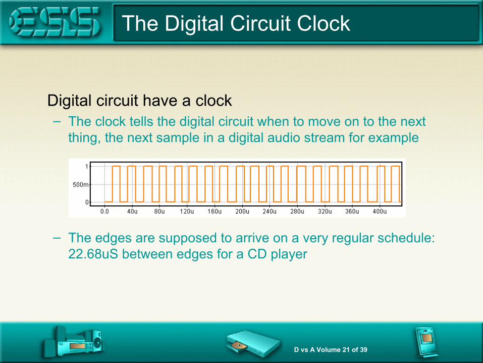
Digital circuit have a clock– The clock tells the digital circuit when to move on to the next
thing, the next sample in a digital audio stream for example
– The edges are supposed to arrive on a very regular schedule:22.68uS between edges for a CD player

D vs A Volume 22 of 39
Perfect regularity is impossible
There is variation in the time interval between edges
– All these times should have been 22.68uS, but they are not:some are faster, some are slower
D vs A Volume 23 of 39
The DAC appears wrong with jitter
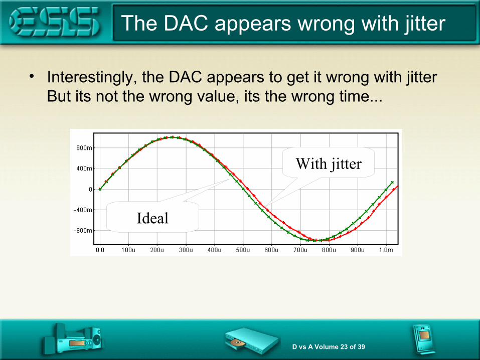
• Interestingly, the DAC appears to get it wrong with jitterBut its not the wrong value, its the wrong time...
Ideal
With jitter
D vs A Volume 24 of 39
Low Jitter Clock
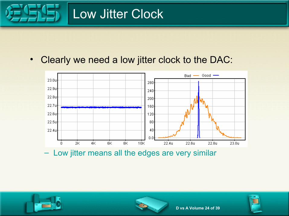
• Clearly we need a low jitter clock to the DAC:
– Low jitter means all the edges are very similar

D vs A Volume 25 of 39
The system level problem
• We cannot use a very good clock at the DACBecause we are not master of the data source!– Any clock we use will eventually get out of step with the data
being sent from the data source, from the CD for example• Our problem is that there is a “transport clock” that is not
in our control that is sending the data to us– We must remain “locked” to this clock

D vs A Volume 26 of 39
Overview of this Presentation
• What is jitter?Why does jitter degrade the perceived audio quality?
• What do Phase Locked Loops do?
What is an Asynchronous Sample Rate Converterand how can that help?
D vs A Volume 27 of 39
Phase Locking solves the problem
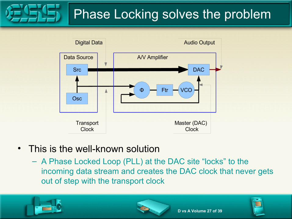
• This is the well-known solution– A Phase Locked Loop (PLL) at the DAC site “locks” to the
incoming data stream and creates the DAC clock that never gets out of step with the transport clock
Osc Φ Ftr VCO
Src DAC Data Source A/V Amplifier
Transport Clock
Master (DAC) Clock
Audio Output Digital Data
D vs A Volume 28 of 39
But the bad news is:
• Audiophiles can hear artifacts from the PLL– Hard as it is to believe, it is undoubtedly true:
Experiments show that the presence of a PLL is audible – it degrades the audio quality
• Work has focused on how to make the PLL inaudible– Audio engineers reduce the phase noise of the PLL
• Use a crystal-based PLL• Use a very high performance loop filter• Etc
• Now manufacturers try to remove the PLL completely– But they require specialist and non-standard data sources....

D vs A Volume 29 of 39
Make the DAC Clock the master
• Put the PLL in the data source– Now the PLL jitter does not degrade quality at all
(even if the jitter in the PLL is high – it does not affect audio quality)
Osc
Src DAC
Data Source A/V Amplifier
Audio OutputDigital Data
ΦFtrVCO
TransportClock
ReferenceClock
D vs A Volume 30 of 39
Is there another way to do this?
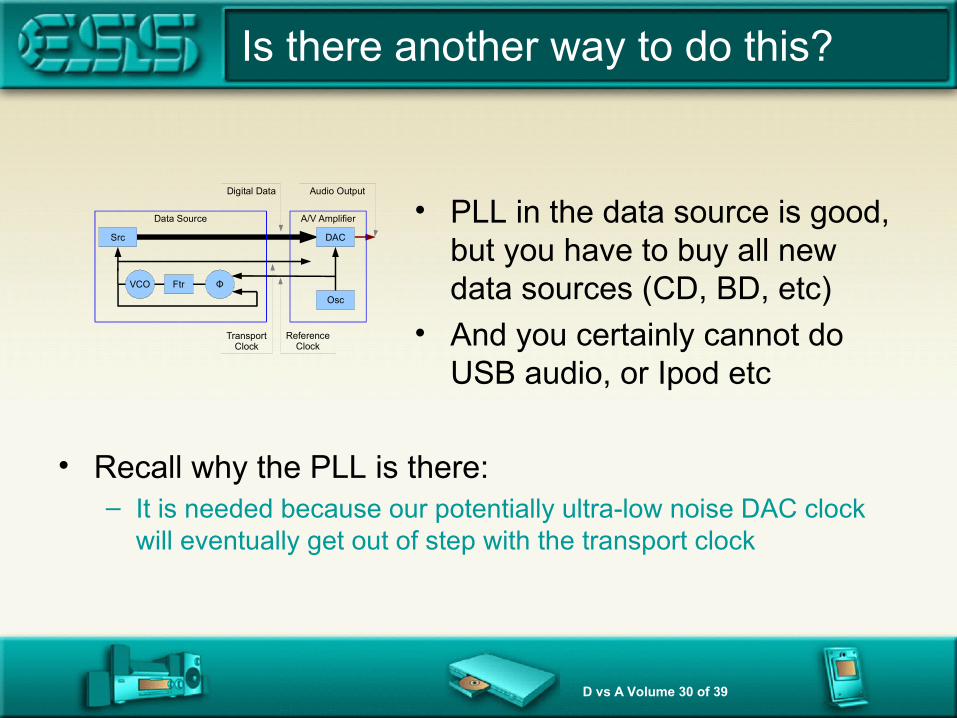
• PLL in the data source is good, but you have to buy all new data sources (CD, BD, etc)
• And you certainly cannot do USB audio, or Ipod etc
Osc
Src DAC
Data Source A/V Amplifier
Audio OutputDigital Data
ΦFtrVCO
TransportClock
ReferenceClock
• Recall why the PLL is there:– It is needed because our potentially ultra-low noise DAC clock
will eventually get out of step with the transport clock
D vs A Volume 31 of 39
Overview of this Presentation
• What is jitter?Why does jitter degrade the perceived audio quality?
• What do Phase Locked Loops do?
What is an Asynchronous Sample Rate Converterand how can that help?
D vs A Volume 32 of 39
Lack of Synchronicity
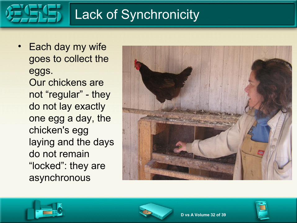
• Each day my wife goes to collect the eggs.Our chickens are not “regular” - they do not lay exactly one egg a day, the chicken's egg laying and the days do not remain “locked”: they are asynchronous

D vs A Volume 33 of 39
Chicken Egg Schedule
• These are the eggs we get.Look at the schedule for one chicken: its egg laying and the days get out of sync. Just like the audio problem, sometimes when we want an egg it is not there.
• Sometimes, when the DAC wants a new sample, it is not there because the transport clock has not delivered it.
Eggs One Chicken
Day 1 6 1
Day 2 8 1
Day 3 6 0
Day 4 6 1
Day 5 7 1
Day 6 8 1
Day 7 7 1
Day 8 6 0
Day 9 6 1
Day 10 7 1
Day 11 7 1
Day 12 6 0
Day 13 8 1
Day 14 9 1
Day 15 8 1
Day 16 7 0
Day 17 6 1
Day 18 6 1
D vs A Volume 34 of 39
Surprising Fact
• There is an algorithm, that given the egg schedule 110111101110111011... as collected only at 8:00am, can calculate the very second that the egg is halfway out of the chicken!– This means that in principle at least, a digital system operating on its
own clock (8.00am each day) asynchronous to the transport clock (the chickens schedule) can figure out exactly when the data should be there (when the egg is coming)
• And this means that in principle we do not need a PLL even though the systems are asynchronous– The algorithm to do this is ESS's patented “Asynchronous Sample Rate
Convertor” and is not the same as the previously known techniques

D vs A Volume 35 of 39
Sabre DAC Clocking Scheme
• Note the ideal aspects:– The very low noise clock goes straight to the DAC– The data source has no PLL: existing CD/BD/USB/IPod all work
• The “Digitally Recovered Transport Clock” is not a clock!– It is the egg algorithm running and telling the ASRC exactly where the data should be (when
the egg was laid)
Osc Φ DCO
Src DAC Data Source Sabre DAC Chip
Transport Clock
Digitally Recovered Transport Clock
Audio Output Digital Data
Osc
ASRC
Master (DAC) Clock

D vs A Volume 36 of 39
What does the ASRC actually do?
• This is the key: what does the ASRC do with the knowledge of where the data “really” is?This is very hard to describe* – but I am going to try– Remarkably, as the data flows into the clock domain of DAC the
ASRC never actually creates or destroys a sample!– It uses the faulty samples in the DAC domain and makes a slight
correction to approximately every 600th one that goes past.– This is all that needs to be done to remove all artifacts of the
asynchronous nature of the transport and DAC clock
*You may wish to read the patents 7,436,333; 7,330,138 and 7,953,782.

D vs A Volume 37 of 39
No PLL at all
• Using the Sabre DAC clocking scheme the jitter is that of the fixed frequency master DAC oscillator– You can buy and use an ultra-high performance clock as
designed to RF applications. It far exceeds any PLL– That clock can be any frequency at all from about 20-100Mhz
• ►The audio quality suffers no degradation due to PLL artifacts
[ For more technical information from ESS email to [email protected] - mention RMAF]

D vs A Volume 38 of 39
Sabre DAC: Conclusions
• ESS delivers to the Audiophile community the best DAC and ADC silicon chips.
• The top of the line “Sabre” products include– HyperStream: DACs and ADCs to true Audiophile levels
without the problems of ΣΔ artifacts– ASRC technology: removes jitter from the signal source without
introducing PLL artifacts– The best digital volume controls (in both DAC and ADC)– More we have not spoken about today, optimized DEM, lowest
power, least susceptibility to EMI, lowest out of band noise, built in SPDIF, built in SADC, 8/4/2/1 channels ... etc etc
Martin Mallinson ESS, 2011 RMAF

D vs A Volume 39 of 39
End of Presentation
Thank you for attending