abcs of z/os system programming volume 1 - uni-leipzig.de ispf, jcl, and sdsf z/os ... tutorial ......
TRANSCRIPT

ibm.com/redbooks
Front cover
ABCs of z/OS SystemProgrammingVolume 1
Paul RogersMiriam GelinskiRedelf Janssen
Joao Natalino OliveiraAlvaro Salla
Valeria Sokal
Introduction to z/OS and storage concepts
TSO/E, ISPF, JCL, and SDSF
z/OS delivery and installation


International Technical Support Organization
ABCs of z/OS System Programming Volume 1
April 2008
SG24-6981-01

© Copyright International Business Machines Corporation 2008. All rights reserved.Note to U.S. Government Users Restricted Rights -- Use, duplication or disclosure restricted by GSA ADP ScheduleContract with IBM Corp.
Second Edition (April 2008)
This edition applies to Version 1 Release 8 of z/OS (5694-A01), Version 1 Release 8 of z/OS.e (5655-G52), and to all subsequent releases and modifications until otherwise indicated in new editions.
Note: Before using this information and the product it supports, read the information in “Notices” on page vii.

Contents
Notices . . . . . . . . . . . . . . . . . . . . . . . . . . . . . . . . . . . . . . . . . . . . . . . . . . . . . . . . . . . . . . . . . viiTrademarks . . . . . . . . . . . . . . . . . . . . . . . . . . . . . . . . . . . . . . . . . . . . . . . . . . . . . . . . . . . . . viii
Preface . . . . . . . . . . . . . . . . . . . . . . . . . . . . . . . . . . . . . . . . . . . . . . . . . . . . . . . . . . . . . . . . . ixThe team that wrote this book . . . . . . . . . . . . . . . . . . . . . . . . . . . . . . . . . . . . . . . . . . . . . . . . ixBecome a published author . . . . . . . . . . . . . . . . . . . . . . . . . . . . . . . . . . . . . . . . . . . . . . . . . . .xComments welcome. . . . . . . . . . . . . . . . . . . . . . . . . . . . . . . . . . . . . . . . . . . . . . . . . . . . . . . . .x
Chapter 1. Introduction to z/OS . . . . . . . . . . . . . . . . . . . . . . . . . . . . . . . . . . . . . . . . . . . . . 11.1 z/OS services . . . . . . . . . . . . . . . . . . . . . . . . . . . . . . . . . . . . . . . . . . . . . . . . . . . . . . . . . 21.2 IBM server and operating system evolution . . . . . . . . . . . . . . . . . . . . . . . . . . . . . . . . . . 41.3 z/OS and z/OS.e . . . . . . . . . . . . . . . . . . . . . . . . . . . . . . . . . . . . . . . . . . . . . . . . . . . . . . . 61.4 Hardware requirements. . . . . . . . . . . . . . . . . . . . . . . . . . . . . . . . . . . . . . . . . . . . . . . . . . 81.5 IBM System z Server: Basic and LPAR mode . . . . . . . . . . . . . . . . . . . . . . . . . . . . . . . . 91.6 z/OS base elements - z/OS V1R8. . . . . . . . . . . . . . . . . . . . . . . . . . . . . . . . . . . . . . . . . 111.7 z/OS optional features. . . . . . . . . . . . . . . . . . . . . . . . . . . . . . . . . . . . . . . . . . . . . . . . . . 151.8 z/OS base control program (BCP) . . . . . . . . . . . . . . . . . . . . . . . . . . . . . . . . . . . . . . . . 181.9 z/OS Security Server: RACF component . . . . . . . . . . . . . . . . . . . . . . . . . . . . . . . . . . . 191.10 Data Facility Storage Management Subsystem (DFSMS) . . . . . . . . . . . . . . . . . . . . . 211.11 DFSMS Extended Remote Copy: XRC. . . . . . . . . . . . . . . . . . . . . . . . . . . . . . . . . . . . 241.12 z/OS Communications Server: TCP/IP . . . . . . . . . . . . . . . . . . . . . . . . . . . . . . . . . . . . 261.13 System Modification Program Extended (SMP/E). . . . . . . . . . . . . . . . . . . . . . . . . . . . 281.14 Time Sharing Option/Extended (TSO/E) . . . . . . . . . . . . . . . . . . . . . . . . . . . . . . . . . . . 301.15 UNIX System Services . . . . . . . . . . . . . . . . . . . . . . . . . . . . . . . . . . . . . . . . . . . . . . . . 321.16 System Management Facility (SMF) . . . . . . . . . . . . . . . . . . . . . . . . . . . . . . . . . . . . . . 341.17 Resource Management Facility (RMF) . . . . . . . . . . . . . . . . . . . . . . . . . . . . . . . . . . . . 361.18 Workload Manager (WLM) . . . . . . . . . . . . . . . . . . . . . . . . . . . . . . . . . . . . . . . . . . . . . 381.19 Infoprint Server . . . . . . . . . . . . . . . . . . . . . . . . . . . . . . . . . . . . . . . . . . . . . . . . . . . . . . 40
Chapter 2. The z/OS system programmer. . . . . . . . . . . . . . . . . . . . . . . . . . . . . . . . . . . . 432.1 z/OS Operating System: the role of a system programmer. . . . . . . . . . . . . . . . . . . . . . 442.2 z/OS system programmer management overview . . . . . . . . . . . . . . . . . . . . . . . . . . . . 462.3 The system programmer and z/OS operations . . . . . . . . . . . . . . . . . . . . . . . . . . . . . . . 482.4 Requirements for z/OS installation . . . . . . . . . . . . . . . . . . . . . . . . . . . . . . . . . . . . . . . . 512.5 Choosing an installation package . . . . . . . . . . . . . . . . . . . . . . . . . . . . . . . . . . . . . . . . . 532.6 Ordering z/OS . . . . . . . . . . . . . . . . . . . . . . . . . . . . . . . . . . . . . . . . . . . . . . . . . . . . . . . . 552.7 Installing z/OS: ServerPac . . . . . . . . . . . . . . . . . . . . . . . . . . . . . . . . . . . . . . . . . . . . . . 562.8 Installing z/OS: Custom-built product delivery option . . . . . . . . . . . . . . . . . . . . . . . . . . 572.9 Installing z/OS: Fee-based packages . . . . . . . . . . . . . . . . . . . . . . . . . . . . . . . . . . . . . . 58
Chapter 3. z/OS storage concepts . . . . . . . . . . . . . . . . . . . . . . . . . . . . . . . . . . . . . . . . . . 593.1 Processor storage overview . . . . . . . . . . . . . . . . . . . . . . . . . . . . . . . . . . . . . . . . . . . . . 603.2 Virtual storage concepts . . . . . . . . . . . . . . . . . . . . . . . . . . . . . . . . . . . . . . . . . . . . . . . . 623.3 Frames, slots, and pages . . . . . . . . . . . . . . . . . . . . . . . . . . . . . . . . . . . . . . . . . . . . . . . 643.4 The address space concept . . . . . . . . . . . . . . . . . . . . . . . . . . . . . . . . . . . . . . . . . . . . . 653.5 Addressing mode and residence mode. . . . . . . . . . . . . . . . . . . . . . . . . . . . . . . . . . . . . 663.6 Storage managers. . . . . . . . . . . . . . . . . . . . . . . . . . . . . . . . . . . . . . . . . . . . . . . . . . . . . 673.7 Virtual Storage Manager . . . . . . . . . . . . . . . . . . . . . . . . . . . . . . . . . . . . . . . . . . . . . . . . 683.8 Real Storage Manager . . . . . . . . . . . . . . . . . . . . . . . . . . . . . . . . . . . . . . . . . . . . . . . . . 69
© Copyright IBM Corp. 2008. All rights reserved. iii

3.9 Auxiliary Storage Manager . . . . . . . . . . . . . . . . . . . . . . . . . . . . . . . . . . . . . . . . . . . . . . 703.10 Paging and swapping . . . . . . . . . . . . . . . . . . . . . . . . . . . . . . . . . . . . . . . . . . . . . . . . . 713.11 Auxiliary page data sets . . . . . . . . . . . . . . . . . . . . . . . . . . . . . . . . . . . . . . . . . . . . . . . 733.12 31-bit address space map. . . . . . . . . . . . . . . . . . . . . . . . . . . . . . . . . . . . . . . . . . . . . . 743.13 The common virtual storage area . . . . . . . . . . . . . . . . . . . . . . . . . . . . . . . . . . . . . . . . 753.14 z/OS nucleus. . . . . . . . . . . . . . . . . . . . . . . . . . . . . . . . . . . . . . . . . . . . . . . . . . . . . . . . 763.15 System queue area (SQA/ESQA) . . . . . . . . . . . . . . . . . . . . . . . . . . . . . . . . . . . . . . . . 773.16 Common service area (CSA and Extended CSA). . . . . . . . . . . . . . . . . . . . . . . . . . . . 783.17 Link pack area (LPA and Extended LPA) . . . . . . . . . . . . . . . . . . . . . . . . . . . . . . . . . . 793.18 31-bit address space private area. . . . . . . . . . . . . . . . . . . . . . . . . . . . . . . . . . . . . . . . 813.19 Data spaces and hiperspace. . . . . . . . . . . . . . . . . . . . . . . . . . . . . . . . . . . . . . . . . . . . 833.20 64-bit address space map. . . . . . . . . . . . . . . . . . . . . . . . . . . . . . . . . . . . . . . . . . . . . . 853.21 Size and number notation . . . . . . . . . . . . . . . . . . . . . . . . . . . . . . . . . . . . . . . . . . . . . . 873.22 Segment tables and page tables in 31-bit addressing . . . . . . . . . . . . . . . . . . . . . . . . 883.23 31-bit virtual address. . . . . . . . . . . . . . . . . . . . . . . . . . . . . . . . . . . . . . . . . . . . . . . . . . 903.24 64-bit virtual address translation . . . . . . . . . . . . . . . . . . . . . . . . . . . . . . . . . . . . . . . . . 913.25 Translating a 64-bit virtual address . . . . . . . . . . . . . . . . . . . . . . . . . . . . . . . . . . . . . . . 933.26 System initialization (IPL process) . . . . . . . . . . . . . . . . . . . . . . . . . . . . . . . . . . . . . . . 943.27 z/OS address spaces . . . . . . . . . . . . . . . . . . . . . . . . . . . . . . . . . . . . . . . . . . . . . . . . . 953.28 Subsystem definitions . . . . . . . . . . . . . . . . . . . . . . . . . . . . . . . . . . . . . . . . . . . . . . . . . 963.29 Multiprogramming and multiprocessing . . . . . . . . . . . . . . . . . . . . . . . . . . . . . . . . . . . 983.30 Program compile, link-edit, and execution . . . . . . . . . . . . . . . . . . . . . . . . . . . . . . . . 1003.31 Library Lookaside (LLA) . . . . . . . . . . . . . . . . . . . . . . . . . . . . . . . . . . . . . . . . . . . . . . 1013.32 Virtual Lookaside Facility (VLF) . . . . . . . . . . . . . . . . . . . . . . . . . . . . . . . . . . . . . . . . 1033.33 Memory hierarchy . . . . . . . . . . . . . . . . . . . . . . . . . . . . . . . . . . . . . . . . . . . . . . . . . . . 104
Chapter 4. TSO/E, ISPF, JCL, and SDSF . . . . . . . . . . . . . . . . . . . . . . . . . . . . . . . . . . . . 1074.1 z/OS facilities for system programmers. . . . . . . . . . . . . . . . . . . . . . . . . . . . . . . . . . . . 1084.2 TSO/E . . . . . . . . . . . . . . . . . . . . . . . . . . . . . . . . . . . . . . . . . . . . . . . . . . . . . . . . . . . . . 1094.3 TSO/E highlights . . . . . . . . . . . . . . . . . . . . . . . . . . . . . . . . . . . . . . . . . . . . . . . . . . . . . 1104.4 TSO/E customization . . . . . . . . . . . . . . . . . . . . . . . . . . . . . . . . . . . . . . . . . . . . . . . . . 1134.5 TSO/E: TCAS start procedure. . . . . . . . . . . . . . . . . . . . . . . . . . . . . . . . . . . . . . . . . . . 1154.6 TSO/E logon procedure . . . . . . . . . . . . . . . . . . . . . . . . . . . . . . . . . . . . . . . . . . . . . . . 1164.7 TSO/E logon process in a VTAM environment . . . . . . . . . . . . . . . . . . . . . . . . . . . . . . 1184.8 TSO/E full-screen logon panel . . . . . . . . . . . . . . . . . . . . . . . . . . . . . . . . . . . . . . . . . . 1194.9 TSO/E line-mode. . . . . . . . . . . . . . . . . . . . . . . . . . . . . . . . . . . . . . . . . . . . . . . . . . . . . 1204.10 Using TSO/E as batch job. . . . . . . . . . . . . . . . . . . . . . . . . . . . . . . . . . . . . . . . . . . . . 1214.11 TSO/E Profile command . . . . . . . . . . . . . . . . . . . . . . . . . . . . . . . . . . . . . . . . . . . . . . 1224.12 TSO/E languages . . . . . . . . . . . . . . . . . . . . . . . . . . . . . . . . . . . . . . . . . . . . . . . . . . . 1234.13 Interactive System Productivity Facility (ISPF) . . . . . . . . . . . . . . . . . . . . . . . . . . . . . 1244.14 ISPF: Data set types supported . . . . . . . . . . . . . . . . . . . . . . . . . . . . . . . . . . . . . . . . 1254.15 ISPF: Data set and member naming conventions. . . . . . . . . . . . . . . . . . . . . . . . . . . 1264.16 ISPF components . . . . . . . . . . . . . . . . . . . . . . . . . . . . . . . . . . . . . . . . . . . . . . . . . . . 1274.17 Sample CLIST to allocate ISPF and SDSF data sets . . . . . . . . . . . . . . . . . . . . . . . . 1294.18 ISPF primary option menu . . . . . . . . . . . . . . . . . . . . . . . . . . . . . . . . . . . . . . . . . . . . 1314.19 ISPF panel areas . . . . . . . . . . . . . . . . . . . . . . . . . . . . . . . . . . . . . . . . . . . . . . . . . . . 1324.20 Action bars . . . . . . . . . . . . . . . . . . . . . . . . . . . . . . . . . . . . . . . . . . . . . . . . . . . . . . . . 1334.21 Customizing your TSO/ISPF/PDF session . . . . . . . . . . . . . . . . . . . . . . . . . . . . . . . . 1344.22 Allocating data sets: Utility option . . . . . . . . . . . . . . . . . . . . . . . . . . . . . . . . . . . . . . . 1354.23 Utility Selection Panel . . . . . . . . . . . . . . . . . . . . . . . . . . . . . . . . . . . . . . . . . . . . . . . . 1364.24 Data Set Utility: Allocating a data set . . . . . . . . . . . . . . . . . . . . . . . . . . . . . . . . . . . . 1374.25 Allocate New Data Set panel . . . . . . . . . . . . . . . . . . . . . . . . . . . . . . . . . . . . . . . . . . 1394.26 Edit function: Option 2. . . . . . . . . . . . . . . . . . . . . . . . . . . . . . . . . . . . . . . . . . . . . . . . 141
iv ABCs of z/OS System Programming Volume 1

4.27 Edit Entry Panel . . . . . . . . . . . . . . . . . . . . . . . . . . . . . . . . . . . . . . . . . . . . . . . . . . . . 1424.28 Editing a data set . . . . . . . . . . . . . . . . . . . . . . . . . . . . . . . . . . . . . . . . . . . . . . . . . . . 1434.29 ISPF edit: Some line commands. . . . . . . . . . . . . . . . . . . . . . . . . . . . . . . . . . . . . . . . 1444.30 ISPF edit panel: Inserting lines . . . . . . . . . . . . . . . . . . . . . . . . . . . . . . . . . . . . . . . . . 1454.31 ISPF edit: Repeating and deleting lines . . . . . . . . . . . . . . . . . . . . . . . . . . . . . . . . . . 1464.32 Edit: Copying lines . . . . . . . . . . . . . . . . . . . . . . . . . . . . . . . . . . . . . . . . . . . . . . . . . . 1474.33 ISPF/PDF edit: Primary commands . . . . . . . . . . . . . . . . . . . . . . . . . . . . . . . . . . . . . 1484.34 ISPF/PDF edit: Profile command . . . . . . . . . . . . . . . . . . . . . . . . . . . . . . . . . . . . . . . 1494.35 ISPF/PDF edit: Saving new or updated files . . . . . . . . . . . . . . . . . . . . . . . . . . . . . . . 1504.36 ISPF Data Set List Utility option . . . . . . . . . . . . . . . . . . . . . . . . . . . . . . . . . . . . . . . . 1514.37 Working with a data set list . . . . . . . . . . . . . . . . . . . . . . . . . . . . . . . . . . . . . . . . . . . . 1534.38 Data Set List Actions. . . . . . . . . . . . . . . . . . . . . . . . . . . . . . . . . . . . . . . . . . . . . . . . . 1544.39 Job control language (JCL) . . . . . . . . . . . . . . . . . . . . . . . . . . . . . . . . . . . . . . . . . . . . 1554.40 JCL introduction . . . . . . . . . . . . . . . . . . . . . . . . . . . . . . . . . . . . . . . . . . . . . . . . . . . . 1564.41 JCL-related actions . . . . . . . . . . . . . . . . . . . . . . . . . . . . . . . . . . . . . . . . . . . . . . . . . . 1584.42 Required control statements . . . . . . . . . . . . . . . . . . . . . . . . . . . . . . . . . . . . . . . . . . . 1594.43 JCL streams and jobs . . . . . . . . . . . . . . . . . . . . . . . . . . . . . . . . . . . . . . . . . . . . . . . . 1604.44 JES control statements in JCL . . . . . . . . . . . . . . . . . . . . . . . . . . . . . . . . . . . . . . . . . 1624.45 Introduction to JCL: Creating a data set . . . . . . . . . . . . . . . . . . . . . . . . . . . . . . . . . . 1634.46 JCL: JOB statement . . . . . . . . . . . . . . . . . . . . . . . . . . . . . . . . . . . . . . . . . . . . . . . . . 1644.47 JCL: EXEC statement . . . . . . . . . . . . . . . . . . . . . . . . . . . . . . . . . . . . . . . . . . . . . . . . 1664.48 JCL: EXEC statement . . . . . . . . . . . . . . . . . . . . . . . . . . . . . . . . . . . . . . . . . . . . . . . . 1684.49 DD statement parameters: DISP, UNIT . . . . . . . . . . . . . . . . . . . . . . . . . . . . . . . . . . 1694.50 DD statement parameters: SPACE, LRECL, BLKSIZE. . . . . . . . . . . . . . . . . . . . . . . 1714.51 Submitting a job . . . . . . . . . . . . . . . . . . . . . . . . . . . . . . . . . . . . . . . . . . . . . . . . . . . . 1734.52 Spool Display and Search Facility (SDSF) . . . . . . . . . . . . . . . . . . . . . . . . . . . . . . . . 1744.53 SDSF: Panels hierarchy . . . . . . . . . . . . . . . . . . . . . . . . . . . . . . . . . . . . . . . . . . . . . . 1754.54 SDSF: Primary option menu . . . . . . . . . . . . . . . . . . . . . . . . . . . . . . . . . . . . . . . . . . . 1764.55 SDSF: Options menu . . . . . . . . . . . . . . . . . . . . . . . . . . . . . . . . . . . . . . . . . . . . . . . . 1774.56 SDSF: Viewing the JES2 output files . . . . . . . . . . . . . . . . . . . . . . . . . . . . . . . . . . . . 1784.57 SDSF: Display Active Users (DA) . . . . . . . . . . . . . . . . . . . . . . . . . . . . . . . . . . . . . . . 1804.58 Issuing MVS and JES commands. . . . . . . . . . . . . . . . . . . . . . . . . . . . . . . . . . . . . . . 1814.59 SDSF: Input queue panel . . . . . . . . . . . . . . . . . . . . . . . . . . . . . . . . . . . . . . . . . . . . . 1824.60 SDSF: Output queue panel . . . . . . . . . . . . . . . . . . . . . . . . . . . . . . . . . . . . . . . . . . . . 1834.61 SDSF: Held Output queue panel. . . . . . . . . . . . . . . . . . . . . . . . . . . . . . . . . . . . . . . . 1844.62 SDSF: Status panel. . . . . . . . . . . . . . . . . . . . . . . . . . . . . . . . . . . . . . . . . . . . . . . . . . 1854.63 SDSF: Tutorial. . . . . . . . . . . . . . . . . . . . . . . . . . . . . . . . . . . . . . . . . . . . . . . . . . . . . . 186
Chapter 5. z/OS delivery and installation . . . . . . . . . . . . . . . . . . . . . . . . . . . . . . . . . . . 1875.1 z/OS installation overview . . . . . . . . . . . . . . . . . . . . . . . . . . . . . . . . . . . . . . . . . . . . . . 1885.2 z/OS release cycle . . . . . . . . . . . . . . . . . . . . . . . . . . . . . . . . . . . . . . . . . . . . . . . . . . . 1895.3 z/OS delivery options . . . . . . . . . . . . . . . . . . . . . . . . . . . . . . . . . . . . . . . . . . . . . . . . . 1905.4 ServerPac service level. . . . . . . . . . . . . . . . . . . . . . . . . . . . . . . . . . . . . . . . . . . . . . . . 1925.5 CBPDO service level. . . . . . . . . . . . . . . . . . . . . . . . . . . . . . . . . . . . . . . . . . . . . . . . . . 1935.6 System and installation requirements . . . . . . . . . . . . . . . . . . . . . . . . . . . . . . . . . . . . . 1945.7 Reviewing your current system . . . . . . . . . . . . . . . . . . . . . . . . . . . . . . . . . . . . . . . . . . 1955.8 The driving and target system. . . . . . . . . . . . . . . . . . . . . . . . . . . . . . . . . . . . . . . . . . . 1965.9 z/OS installation using ServerPac. . . . . . . . . . . . . . . . . . . . . . . . . . . . . . . . . . . . . . . . 1975.10 Installing the CustomPac dialogs . . . . . . . . . . . . . . . . . . . . . . . . . . . . . . . . . . . . . . . 1985.11 The RIM tape samples . . . . . . . . . . . . . . . . . . . . . . . . . . . . . . . . . . . . . . . . . . . . . . . 1995.12 Starting the CustomPac dialogs . . . . . . . . . . . . . . . . . . . . . . . . . . . . . . . . . . . . . . . . 2005.13 Receiving the ServerPac order . . . . . . . . . . . . . . . . . . . . . . . . . . . . . . . . . . . . . . . . . 2015.14 Order Receive panel . . . . . . . . . . . . . . . . . . . . . . . . . . . . . . . . . . . . . . . . . . . . . . . . . 202
Contents v
5.15 Receive an order from tape. . . . . . . . . . . . . . . . . . . . . . . . . . . . . . . . . . . . . . . . . . . . 2035.16 Edit JOB statement panel . . . . . . . . . . . . . . . . . . . . . . . . . . . . . . . . . . . . . . . . . . . . . 2045.17 Edit RECEIVE job panel . . . . . . . . . . . . . . . . . . . . . . . . . . . . . . . . . . . . . . . . . . . . . . 2055.18 Selecting an order to install . . . . . . . . . . . . . . . . . . . . . . . . . . . . . . . . . . . . . . . . . . . . 2065.19 Installation dialog . . . . . . . . . . . . . . . . . . . . . . . . . . . . . . . . . . . . . . . . . . . . . . . . . . . 2075.20 Choosing the installation type panel . . . . . . . . . . . . . . . . . . . . . . . . . . . . . . . . . . . . . 2085.21 Selecting a JES for the configuration . . . . . . . . . . . . . . . . . . . . . . . . . . . . . . . . . . . . 2095.22 Create Configuration panel . . . . . . . . . . . . . . . . . . . . . . . . . . . . . . . . . . . . . . . . . . . . 2105.23 Installation Variables panel . . . . . . . . . . . . . . . . . . . . . . . . . . . . . . . . . . . . . . . . . . . . 2115.24 Define ZONE Information panel . . . . . . . . . . . . . . . . . . . . . . . . . . . . . . . . . . . . . . . . 2125.25 Modify System Layout Options panel . . . . . . . . . . . . . . . . . . . . . . . . . . . . . . . . . . . . 2135.26 Summary of Features/Elements panel . . . . . . . . . . . . . . . . . . . . . . . . . . . . . . . . . . . 2145.27 Summary of data sets of a feature or element . . . . . . . . . . . . . . . . . . . . . . . . . . . . . 2155.28 Summary of Physical Volumes panel . . . . . . . . . . . . . . . . . . . . . . . . . . . . . . . . . . . . 2165.29 Creating the recommended system layout . . . . . . . . . . . . . . . . . . . . . . . . . . . . . . . . 2175.30 Current Volume Configuration panel . . . . . . . . . . . . . . . . . . . . . . . . . . . . . . . . . . . . . 2185.31 Display and change volume attributes panel . . . . . . . . . . . . . . . . . . . . . . . . . . . . . . 2195.32 Define alias-to-catalog relationships . . . . . . . . . . . . . . . . . . . . . . . . . . . . . . . . . . . . . 2205.33 Define system-specific alias (SSA) . . . . . . . . . . . . . . . . . . . . . . . . . . . . . . . . . . . . . . 2215.34 Define SSA and CATALOG Data panel . . . . . . . . . . . . . . . . . . . . . . . . . . . . . . . . . . 2225.35 Job Selection List panel . . . . . . . . . . . . . . . . . . . . . . . . . . . . . . . . . . . . . . . . . . . . . . 2235.36 GENERATE File Tailored Installation Jobs panel . . . . . . . . . . . . . . . . . . . . . . . . . . . 2245.37 Displaying the processing log . . . . . . . . . . . . . . . . . . . . . . . . . . . . . . . . . . . . . . . . . . 2255.38 Save Configuration panel . . . . . . . . . . . . . . . . . . . . . . . . . . . . . . . . . . . . . . . . . . . . . 2265.39 IBM software ShopzSeries . . . . . . . . . . . . . . . . . . . . . . . . . . . . . . . . . . . . . . . . . . . . 2275.40 Shop zSeries order process . . . . . . . . . . . . . . . . . . . . . . . . . . . . . . . . . . . . . . . . . . . 2285.41 Specify order basics step 1 of 8 . . . . . . . . . . . . . . . . . . . . . . . . . . . . . . . . . . . . . . . . 2295.42 Select hardware systems step 2 of 8 . . . . . . . . . . . . . . . . . . . . . . . . . . . . . . . . . . . . 2305.43 Report installed software step 3 of 8 . . . . . . . . . . . . . . . . . . . . . . . . . . . . . . . . . . . . . 2315.44 Shop for products step 4 of 8 . . . . . . . . . . . . . . . . . . . . . . . . . . . . . . . . . . . . . . . . . . 2325.45 Shop catalog . . . . . . . . . . . . . . . . . . . . . . . . . . . . . . . . . . . . . . . . . . . . . . . . . . . . . . . 2335.46 Specify order contents step 5 of 8. . . . . . . . . . . . . . . . . . . . . . . . . . . . . . . . . . . . . . . 2345.47 Select new licenses step 6 of 8. . . . . . . . . . . . . . . . . . . . . . . . . . . . . . . . . . . . . . . . . 2355.48 Specify delivery options step 7 of 8. . . . . . . . . . . . . . . . . . . . . . . . . . . . . . . . . . . . . . 2365.49 Review and submit order step 8 of 8. . . . . . . . . . . . . . . . . . . . . . . . . . . . . . . . . . . . . 2385.50 In process orders . . . . . . . . . . . . . . . . . . . . . . . . . . . . . . . . . . . . . . . . . . . . . . . . . . . 2395.51 Finished order . . . . . . . . . . . . . . . . . . . . . . . . . . . . . . . . . . . . . . . . . . . . . . . . . . . . . . 2405.52 Download order information . . . . . . . . . . . . . . . . . . . . . . . . . . . . . . . . . . . . . . . . . . . 2415.53 Download instructions . . . . . . . . . . . . . . . . . . . . . . . . . . . . . . . . . . . . . . . . . . . . . . . . 242
Chapter 6. z/OS maintenance concepts . . . . . . . . . . . . . . . . . . . . . . . . . . . . . . . . . . . . 2436.1 Aspects of software management . . . . . . . . . . . . . . . . . . . . . . . . . . . . . . . . . . . . . . . . 2446.2 Software management tasks. . . . . . . . . . . . . . . . . . . . . . . . . . . . . . . . . . . . . . . . . . . . 2466.3 The z/OS software management cycle . . . . . . . . . . . . . . . . . . . . . . . . . . . . . . . . . . . . 2486.4 How current should your software be . . . . . . . . . . . . . . . . . . . . . . . . . . . . . . . . . . . . . 249
Related publications . . . . . . . . . . . . . . . . . . . . . . . . . . . . . . . . . . . . . . . . . . . . . . . . . . . . 251IBM Redbooks . . . . . . . . . . . . . . . . . . . . . . . . . . . . . . . . . . . . . . . . . . . . . . . . . . . . . . . . . . 251Other publications . . . . . . . . . . . . . . . . . . . . . . . . . . . . . . . . . . . . . . . . . . . . . . . . . . . . . . . 251Online resources . . . . . . . . . . . . . . . . . . . . . . . . . . . . . . . . . . . . . . . . . . . . . . . . . . . . . . . . 251How to get IBM Redbooks . . . . . . . . . . . . . . . . . . . . . . . . . . . . . . . . . . . . . . . . . . . . . . . . . 252Help from IBM . . . . . . . . . . . . . . . . . . . . . . . . . . . . . . . . . . . . . . . . . . . . . . . . . . . . . . . . . . 252
vi ABCs of z/OS System Programming Volume 1

Notices
This information was developed for products and services offered in the U.S.A.
IBM may not offer the products, services, or features discussed in this document in other countries. Consult your local IBM representative for information on the products and services currently available in your area. Any reference to an IBM product, program, or service is not intended to state or imply that only that IBM product, program, or service may be used. Any functionally equivalent product, program, or service that does not infringe any IBM intellectual property right may be used instead. However, it is the user's responsibility to evaluate and verify the operation of any non-IBM product, program, or service.
IBM may have patents or pending patent applications covering subject matter described in this document. The furnishing of this document does not give you any license to these patents. You can send license inquiries, in writing, to: IBM Director of Licensing, IBM Corporation, North Castle Drive, Armonk, NY 10504-1785 U.S.A.
The following paragraph does not apply to the United Kingdom or any other country where such provisions are inconsistent with local law: INTERNATIONAL BUSINESS MACHINES CORPORATION PROVIDES THIS PUBLICATION "AS IS" WITHOUT WARRANTY OF ANY KIND, EITHER EXPRESS OR IMPLIED, INCLUDING, BUT NOT LIMITED TO, THE IMPLIED WARRANTIES OF NON-INFRINGEMENT, MERCHANTABILITY OR FITNESS FOR A PARTICULAR PURPOSE. Some states do not allow disclaimer of express or implied warranties in certain transactions, therefore, this statement may not apply to you.
This information could include technical inaccuracies or typographical errors. Changes are periodically made to the information herein; these changes will be incorporated in new editions of the publication. IBM may make improvements and/or changes in the product(s) and/or the program(s) described in this publication at any time without notice.
Any references in this information to non-IBM Web sites are provided for convenience only and do not in any manner serve as an endorsement of those Web sites. The materials at those Web sites are not part of the materials for this IBM product and use of those Web sites is at your own risk.
IBM may use or distribute any of the information you supply in any way it believes appropriate without incurring any obligation to you.
Information concerning non-IBM products was obtained from the suppliers of those products, their published announcements or other publicly available sources. IBM has not tested those products and cannot confirm the accuracy of performance, compatibility or any other claims related to non-IBM products. Questions on the capabilities of non-IBM products should be addressed to the suppliers of those products.
This information contains examples of data and reports used in daily business operations. To illustrate them as completely as possible, the examples include the names of individuals, companies, brands, and products. All of these names are fictitious and any similarity to the names and addresses used by an actual business enterprise is entirely coincidental.
COPYRIGHT LICENSE:
This information contains sample application programs in source language, which illustrate programming techniques on various operating platforms. You may copy, modify, and distribute these sample programs in any form without payment to IBM, for the purposes of developing, using, marketing or distributing application programs conforming to the application programming interface for the operating platform for which the sample programs are written. These examples have not been thoroughly tested under all conditions. IBM, therefore, cannot guarantee or imply reliability, serviceability, or function of these programs.
© Copyright IBM Corp. 2008. All rights reserved. vii

Trademarks
IBM, the IBM logo, and ibm.com are trademarks or registered trademarks of International Business Machines Corporation in the United States, other countries, or both. These and other IBM trademarked terms are marked on their first occurrence in this information with the appropriate symbol (® or ™), indicating US registered or common law trademarks owned by IBM at the time this information was published. Such trademarks may also be registered or common law trademarks in other countries. A current list of IBM trademarks is available on the Web at http://www.ibm.com/legal/copytrade/shtml.
The following terms are trademarks of the International Business Machines Corporation in the United States, other countries, or both:
Advanced Peer-to-Peer Networking®AIX®BookManager®CICS®CUA®Domino®DB2®DFS™DFSMS™DFSMSdfp™DFSMSdss™DFSMShsm™DFSMSrmm™DFSORT™DS8000™Enterprise Storage Server®ES/9000®ESCON®First Failure Support Technology™FlashCopy®FFST™FICON®Geographically Dispersed Parallel
Sysplex™
GDDM®GDPS®IBM®IBMLink™IMS™IMS/ESA®IP PrintWay™Language Environment®Lotus®Multiprise®MVS™MVS/ESA™MVS/XA™NetSpool™NetView®Open Class®OS/2®OS/390®Parallel Sysplex®PrintWay™ProductPac®PR/SM™RACF®RAMAC®
Redbooks (logo) ®Redbooks®RETAIN®REXX™RMF™S/360™S/370™S/390®ServicePac®System z™System z9®System/360™System/370™SystemPac®SOM®Tivoli®TotalStorage®Virtualization Engine™VTAM®WebSphere®z/Architecture®z/OS®zSeries®z9™
The following terms are trademarks of other companies:
Snapshot, and the NetApp logo are trademarks or registered trademarks of NetApp, Inc. in the U.S. and other countries.
Java, RSM, Solaris, Virtual Storage Manager, and all Java-based trademarks are trademarks of Sun Microsystems, Inc. in the United States, other countries, or both.
Microsoft, Windows, and the Windows logo are trademarks of Microsoft Corporation in the United States, other countries, or both.
UNIX is a registered trademark of The Open Group in the United States and other countries.
Linux is a trademark of Linus Torvalds in the United States, other countries, or both.
Other company, product, or service names may be trademarks or service marks of others.
viii ABCs of z/OS System Programming Volume 1

Preface
The ABCs of z/OS® System Programming is an 11-volume collection that provides an intro-duction to the z/OS operating system and the hardware architecture. Whether you are a beginner or an experienced system programmer, the ABCs collection provides the informa-tion that you need to start your research into z/OS and related subjects. If you would like to become more familiar with z/OS in your current environment, or if you are evaluating plat-forms to consolidate your e-business applications, the ABCs collection will serve as a power-ful technical tool.
Volume 1 provides an updated understanding of the software and zSeries® architecture, and explains how it is used together with the z/OS operating system. This includes the main com-ponents of z/OS needed to customize and install the z/OS operating system.
The contents of the other volumes are as follows:
� Volume 2: z/OS implementation and daily maintenance, defining subsystems, JES2 and JES3, LPA, LNKLST, authorized libraries, SMP/E, Language Environment®
� Volume 3: Introduction to DFSMS™, data set basics storage management hardware and software, catalogs, and DFSMStvs
� Volume 4: Communication Server, TCP/IP, and VTAM®
� Volume 5: Base and Parallel Sysplex®, System Logger, Resource Recovery Services (RRS), global resource serialization (GRS), z/OS system operations, automatic restart management (ARM), Geographically Dispersed Parallel Sysplex™ (GDPS®)
� Volume 6: Introduction to security, RACF®, Digital certificates and PKI, Kerberos, cryptography and z990 integrated cryptography, zSeries firewall technologies, LDAP, and Enterprise identity mapping (EIM)
� Volume 7: Printing in a z/OS environment, Infoprint Server and Infoprint Central
� Volume 8: An introduction to z/OS problem diagnosis
� Volume 9: z/OS UNIX® System Services
� Volume 10: Introduction to z/Architecture®, zSeries processor design, zSeries connectivity, LPAR concepts, HCD, and DS8000™
� Volume 11: Capacity planning, performance management, WLM, RMF™, and SMF
The team that wrote this book
This book was produced by a team of specialists from around the world working at the International Technical Support Organization, Poughkeepsie Center.
Paul Rogers is a Consulting IT Specialist at the International Technical Support Organization, Poughkeepsie Center. He writes extensively and teaches IBM® classes worldwide on various aspects of z/OS, UNIX System Services, Infoprint Server, and JES3. Before joining the ITSO 20 years ago, Paul worked in the IBM Installation Support Center (ISC) in Greenford, England, providing OS/390® and JES support for IBM EMEA and the Washington Systems Center. He has worked for IBM for 40 years.
Redelf Janssen is an IT Architect in IBM System z9™ Technical Sales, Bremen, Germany. He holds a degree in Computer Science from the University of Bremen and joined IBM in
© Copyright IBM Corp. 2008. All rights reserved. ix
1988. He is responsible for supporting IBM System z9 customers in Germany. His areas of expertise include IBM System z9, z/OS, storage management, and availability management. Redelf has co-authored IBM Redbooks® about several OS/390 and z/OS releases, as well as ABCs of z/OS System Programming.
Alvaro Salla is an IBM retiree who worked for IBM for more than 30 years, specializing in large systems. He has co-authored many IBM Redbooks publications and spent many years teaching about large systems from S/360™ to S/390®. He has a degree in Chemical Engineering from the University of Sao Paulo, Brazil.
Thanks to the authors of the previous edition of this book. Authors of the first edition, ABCs of z/OS System Programming Volume 1, published in December 2003, were:
Miriam Gelinski is a staff member of Maffei Consulting Group, where she is responsible for supporting customer planning and installing zSeries software. Miriam holds a Bachelor’s degree in Information Systems from the Universidade São Marcos. Before joining the Maffei Consulting Group, Miriam worked for IBM zSeries brand for two years, where she was responsible for implementing new workloads on zSeries.
Joao Natalino Oliveira is a Certified I/T Consulting Specialist for IBM zSeries in Brazil, where he provides support for Brazil and Latin America. He has 28 years of experience in large systems, including MVS™, OS/390, and z/OS. Joao’s areas of expertise include performance and capacity planning, server consolidation, and system programming. He holds a Bachelor’s degree in Mathematics and Data Processing from Fund. Santo Andre, Brazil.
Alvaro Salla (see above).
Valeria Sokal is an MVS system programmer at an IBM customer. She has 14 years of experience as a mainframe system programmer.
Become a published author
Join us for a two- to six-week residency program! Help write a book dealing with specific products or solutions, while getting hands-on experience with leading-edge technologies. You will have the opportunity to team with IBM technical professionals, Business Partners, and Clients.
Your efforts will help increase product acceptance and customer satisfaction. As a bonus, you will develop a network of contacts in IBM development labs, and increase your productivity and marketability.
Find out more about the residency program, browse the residency index, and apply online at:
ibm.com/redbooks/residencies.html
Comments welcome
Your comments are important to us!
We want our books to be as helpful as possible. Send us your comments about this book or other IBM Redbooks in one of the following ways:
� Use the online Contact us review Redbooks form found at:
ibm.com/redbooks
x ABCs of z/OS System Programming Volume 1

� Send your comments in an e-mail to:
� Mail your comments to:
IBM Corporation, International Technical Support OrganizationDept. HYTD Mail Station P0992455 South RoadPoughkeepsie, NY 12601-5400
Preface xi

xii ABCs of z/OS System Programming Volume 1

Chapter 1. Introduction to z/OS
z/OS is an integrated enterprise server operating system. It incorporates into one product a leading-edge and open communications server, distributed data and file services, Parallel Sysplex system support, object-oriented programming, distributed computer environment (DCE), and an open application interface. As such, it is uniquely suited to integrate today's heterogeneous and multi-vendor environments.
Although the official product name of the operating system is z/OS, the former product name, MVS, is still used when describing any aspect of the operating system.
By incorporating the base operating system, z/OS continues to build on the classic strengths of MVS: reliability, continuous availability features, and security. This provides a scalable system that supports massive transaction volumes and large numbers of users with high performance, as well as advanced system and network management, security, and 24/7 availability.
Businesses are relying on mainframe servers to power their transformation into on demand enterprises. Together, IBM System z™ and z/OS deliver industry-leading capabilities designed to help reduce IT complexity and increase business flexibility while driving down costs. The IBM mainframe is ready to help leverage, extend, and integrate core business applications. It is positioned as a leading platform to manage and integrate your IT operating environment. With middleware and tools to complete the system, you can begin to make on demand a reality by using the most important asset you have, your z/OS mainframe. From automation to advanced virtualization technologies and open and industry standards, z/OS can help deliver competitive advantages for an on demand business.
This chapter presents an overview of the z/OS operating system:
� The z/OS operation system evolution� The hardware required to install and run z/OS � Differences between z/OS and z/OS.e� The z/OS base and optional products, with a brief description of some of them� The z/OS products requiring customization� The system programmer skills needed to install and maintain the z/OS operating system� The requirements to install z/OS� The installation package delivery options
1
© Copyright IBM Corp. 2008. All rights reserved. 1

1.1 z/OS services
Figure 1-1 z/OS services
z/OS servicesz/OS, as an operating system, provides program management services that let you create, load, modify, list, read, and copy executable programs.
The z/OS system provides solutions for the following major areas:
� Data management: z/OS provides a set of functions to manage storage resources on the system, support storage and retrieval of data on disk, optical and tape devices, program management functions, and device management functions to define and control the operation of input and output storage devices. Distributed File Manager (DFM) supports access to remote data and storage resources.
� Softcopy publications services: These services improve productivity in systems installation and management.
� Security services: Security and Cryptographic Services are a set of products and features used to control access to resources, and to audit and manage the accesses with appropriate centralized or decentralized control. These services form the basis for all security services for traditional applications, UNIX applications, and distributed systems.
� System management services: The functions and features provided with z/OS allow robust control and automation of the basic processes of z/OS, thus increasing availability, improving productivity of system programmers, and providing a consistent approach for configuring z/OS components of products.
Net
wor
k C
omm
unic
atio
n
Ser
vice
s
Syst
em M
anag
emen
t
Serv
ices
Sec
urity
Ser
vice
sA
pp
lication
En
ablem
ent
Services
e-Business Services
Softc
opy
Publ
icat
ions
Sup
port
Data
Man
agem
ent
Distributed com
puting
Services
UN
IX S
ystem S
ervices
Print Services
64-bit z/Architecture
z/OS
2 ABCs of z/OS System Programming Volume 1

� Network communication services: z/OS enables world class TCP/IP and SNA networking support; multivendor, multiplatform connectivity; connectivity to a broad set of users; and support for multiple protocols.
� Applications enablement services: These services provide a solid infrastructure in which you can build new applications, extend existing applications, and run OLTP and batch processes.
� UNIX System Services: z/OS contains the UNIX applications services (shell, utilities, and debugger) and the UNIX system services (kernel and runtime environment). The shell and utilities provide the standard command interface familiar to interactive UNIX users. z/OS includes all the commands and utilities specified in the X/OPEN XPG4.2. With Language Environment, z/OS supports industry standards for C programming, shell and utilities, client/server applications, and the majority of the standards for thread management, thus allowing transparent data exchange and easy portability of applications in an open environment.
� Distributed computing services: These services are achieved by a set of features and functions. Network File System acts as a file server to workstations, personal computers, or other authorized systems in a TCP/IP network. Remote files are mounted from the mainframe (z/OS) to appear as local directories and files on the client system. DCE enables data encryption standard (DES) algorithms and the commercial data masking facility (CDMF). Distributed File Services (DFS™) SMB allows users to access data in a distributed environment across a wide range of IBM and non-IBM platforms. SMB can automatically handle the conversion between ASCII and EBCDIC.
� e-Business services: The IBM HTTP Server provides for scalable, high performance Web serving for critical e-business applications. It is exclusive to z/OS. This element was previously known as a base element of z/OS under the names Lotus® Domino® Go, the Internet Connection Secure Server (ICSS), and the Internet Connection Server (ICS).
� Print services: Application output can be electronically distributed and printed or presented over the Web.
z/OS functional enhancementsz/OS Version 1Release 1 was introduced as a replacement for the last release of OS/390. There were ten releases of OS/390, with a new release shipped every six months. This book is based on z/OS Release 1 Version 8. This release was made generally available in September 2006.
z/OS (program number 5694-A01), the next generation of the premier System z operating system, enables you to manage the volatility of e-business workloads. z/OS delivers the highest qualities of service for enterprise transactions and data, and extends these qualities to new applications using the latest software technologies.
Some highlights of z/OS are:
� The 64-bit z/Architecture implemented by z/OS and the IBM System z processors eliminates bottlenecks associated with the lack of addressable memory. The 64-bit real (central) storage support eliminates expanded storage, helps to eliminate paging, and may allow you to consolidate your current systems into fewer logical partitions (LPARs) or to a single native image.
Chapter 1. Introduction to z/OS 3

1.2 IBM server and operating system evolution
Figure 1-2 Architecture and operating system evolution
Software and hardware evolutionEnterprise system hardware was transformed by the introduction of the z/OS Parallel Servers. Based on the complementary metal oxide semiconductor (CMOS) technology, these parallel systems are smaller in size and larger in capacity than their predecessors, and deliver performance at a lower cost.
With the introduction of the S/390 Parallel Servers in 1994, the mainframe was revived. The CMOS technology offers mainframe computing power at a lower cost. The zSeries CMOS machines can be connected with other zSeries or S/390 CMOS machines or even traditional ES/9000® machines to form a Parallel Sysplex. The sysplex offers high availability and the option to add capacity in small increments.
The transformation of mainframe hardware, together with business requirements for information technology (IT), are the driving forces behind changes in the operating system software. In 2001, the z/OS system was introduced as the zSeries server operating system. z/OS extends the S/390 architecture to provide the enterprise-wide client/server infrastructure and tools that businesses need for fast, flexible deployment of new applications.
z/Architecturez/Architecture is the next step in the evolution from the System/360™ to the System/370™, System/370 extended architecture (370-XA), Enterprise Systems Architecture/370* (ESA/370), and Enterprise Systems Architecture/390 (ESA/390). z/Architecture includes all of
MVS/370
S/370
MVS/XA
S/370-XA
MVS/ESA V4
S/390
MVS/ESA V3
S/370
MVS/ESA V5
S/390
OS/390
S/390
z/OS - z/OS.e
z/Architecture
Architecture evolution
S/360S/370
S/370-XAESA/370ESA/390
S/390z/Architecture
S/360
ESA/370
ESA/390
4 ABCs of z/OS System Programming Volume 1

the facilities of ESA/390 except for the asynchronous-pageout, asynchronous-data-mover, program-call-fast, and vector facilities.
z/Architecture also provides significant extensions, as follows:
� It provides 64-bit general registers and control registers.
� A 64-bit addressing mode, in addition to the 24-bit and 31-bit addressing modes of ESA/390, which are carried forward to z/Architecture.
Both operand addresses and instruction addresses can be 64-bit addresses. The program-status word (PSW) is expanded to 16 bytes to contain the larger instruction address. The PSW also contains a newly assigned bit that specifies the 64-bit addressing mode.
� Up to three additional levels of dynamic-address-translation (DAT) tables, called region tables, for translating 64-bit virtual addresses.
A virtual address space may be specified either by a segment-table designation as in ESA/390, or by a region-table designation, and either of these types of designation is called an address-space-control element (ASCE). An ASCE may alternatively be a real-space designation that causes virtual addresses to be treated simply as real addresses without the use of DAT tables.
� An 8 K-byte prefix area for containing larger old and new PSWs and register save areas.
� Many new instructions, many of which operate on 64-bit binary integers.
Note: For a more detailed description of z/Architecture, see ABCs of z/OS System Programming Volume 10, SG24-6990.
Chapter 1. Introduction to z/OS 5

1.3 z/OS and z/OS.e
Figure 1-3 z/OS and z/OS.e operating system
z/OS and z/OS.e operating systems hardwarez/OS, the next generation of the OS/390 operating system, enables you to manage the volatility of e-business workloads. z/OS delivers the highest qualities of service for enterprise transactions and data, and extends these qualities to new applications using the latest software technologies. z/OS and z/OS.e use the same operating system software (their code is identical). Upon Initial Program Load (IPL), custom parameters invoke an operating environment that is comparable to z/OS in all aspects of operation, service, management, reporting, and zSeries hardware functionality. No new skills are required for z/OS.e.
z/OS can run in any IBM System z servers (z9 EC, z9 BC, z900, z800, z890, and z990). z/OS.e runs on the zSeries (z800, z890, and z9 BC) servers or in any comparable non-IBM server.
z/OS and workloadsThe best platform for integrating Web-based transaction processing, e-business, and enterprise applications and database serving is z/OS on zSeries, the premier platform for enterprise-scale workloads. Its qualities of service in terms of reliability, scalability, security, availability are undisputed and unrivalled in the industry. The value is two-fold, because z/OS is not only the most robust and reliable enterprise platform, but also has a history of managing a large percentage of the world's business data and transactions. The finance industry, the transportation industry, health, government all rely on z/OS to store, manage, and use their data efficiently and securely. Offering the same value as this technology, IBM introduces z/OS.e.
z/OSz/900
z/990z/800
z9 EC or z9 BC
z/OS.e
z/890
6 ABCs of z/OS System Programming Volume 1

z/OS.e and workloadsIBM introduced z/OS.e as a cost-effective way to harness the power, value, and qualities of service of z/OS on zSeries for (and to extend it to) new applications; for example, to drive your business into the Web space with an application server such as WebSphere® and access to your DB2® data. z/OS.e opens up the possibility for that data to be available for all kinds of new Web applications.
z/OS.e is unique for the zSeries 890 (z890), zSeries 800 (z800), and System z9 Business Class (z9 BC) servers, providing select functions at an exceptional price. z/OS.e is intended to help customers exploit the fast growing world of on demand business by making the deployment of new application workloads on the z890, z800, and z9 BC attractively priced.
At only a fraction of the cost of z/OS versions in a traditional workload environment, z/OS.e makes the decision to run new workloads on the mainframe easy due to its reduced total cost of ownership and exceptional robustness and functionality. z/OS.e and z800 together may reduce the total cost of ownership of hardware, software, people, and environmentals, thus making the combination very cost-effective for deploying new applications or integrating existing ones.
z/OS.e uses the same code base as z/OS with custom parameters and invokes an operating environment designed to be comparable to z/OS in service, management, reporting, and reliability. In addition, z/OS.e can invoke IBM System z hardware functionality just as z/OS does. No new z/OS skills and service procedures are required for z/OS.e.
z/OS.e is specifically designed for new workloads such as Java™, Enterprise Java, C/C++ and Web-based data transaction processing applications, giving these workloads a price-to-performance ratio that customers expect.
z/OS.e V1R8 is the last release of z/OS.e. Starting with z/OS V1R9, zNALC (z New Application License Charging) will replace z/OS.e as a new software license charge model.
Important: Beginning with z/OS V1R6, z/OS can only be IPLed in z/Architecture mode on z/Architecture servers (IBM System z9, z990, z890, z900, and z800) and does not run on G5, G6, or Multiprise® 3000 servers.
Chapter 1. Introduction to z/OS 7

1.4 Hardware requirements
Figure 1-4 Hardware requirements
Hardware requirementsThe base z/OS operating system executes in a processor and resides in the processor storage during execution. The z/OS operating system is commonly referred to as the system software.
The hardware consists of the processors and other devices such as a direct access storage device (DASD), tape, and consoles. Tape and DASD are used for system functions and by user programs that execute in a z/OS environment. When you order z/OS, you receive your order on tape cartridges. When you install the system from tape, the system code is then stored on DASD volumes. Once the system is customized and ready for operation, system consoles are required to start and operate the z/OS system. Not shown in Figure 1-4 are the control units that connect the CPU (processor) to the other tape, DASD, and console devices. The main concepts shown here are:
Software The z/OS operating system consists of load modules and is often called executable code. These load modules are placed onto DASD volumes in load libraries during a system install process.
Hardware The system hardware consists of all the devices, controllers, and processors that make up a z/OS complex.
Devices Shown in the figure are the tape, DASD, and console devices. There are many other types of devices that are discussed later in this document.
Storage Central storage, often called real or main storage, is where the z/OS operating system executes. Also, all user programs share the storage of the processor with the operating system.
Consoles
System(Hardware)
DASD
IBM System z9
Tape
z/OSOperatingSystem
Central Storage
8 ABCs of z/OS System Programming Volume 1

1.5 IBM System z Server: Basic and LPAR mode
Figure 1-5 Basic mode and LPAR mode
Basic mode and LPAR modeThe hardware can be used in two modes:
LPAR mode Logically partitioned (LPAR) mode is a central processor (CP) Power-on Reset mode that enables use of the Processor Resource/System Manager (PR/SM™) feature and allows an operator to allocate CP hardware resources (including central processor, central storage, and channel paths) among multiple logical partitions (LPs). z/OS as the operating system runs in each LPAR in the machine with all server resources (CPs, storage, and channels).
Basic mode This is a central processor mode that does not use logical partitioning, with the CP running one copy of the z/OS operating system.
When a server is in Basic mode, all server resources (CPs, storage, and channels) are available to the one operating system. All the physical CPs are used in dedicated mode for the one operating system. Any excess CP resource is wasted, because no other system has access to it.
Situations still exist where servers are run in Basic mode (for example, if the z/OS system needs to use the entire capacity of the server). However, because of the huge capacity of modern servers, this is becoming less and less common.
Basic mode
SYSTEM IMAGE A
SYSTEM IMAGE A
SYSTEM IMAGE B
SYSTEM IMAGE C
IBM System z Server
LPAR mode
.
Chapter 1. Introduction to z/OS 9

Note: You can change the processor mode from BASIC to LPAR. You first have to define partitions for the processor and add them to the channel path access and candidate lists. Then change the processor configuration mode, and adapt the channel path modes if needed.
You change the processor mode from LPAR to BASIC. You must change all channel path operation modes that are defined as shared to DED, or REC. In addition, you must delete the duplicate devices (you can also disconnect the channels from the control units instead of deleting the devices directly). Then change the processor configuration mode from LPAR to BASIC.
10 ABCs of z/OS System Programming Volume 1

1.6 z/OS base elements - z/OS V1R8
Figure 1-6 z/OS base elements with z/OS V1R8
z/OS base elementsThe z/OS system consists of base elements that deliver essential operating functions—in addition to the services provided by the BCP functions—such as communications support, online access, host graphics, and online viewing of publications.
Shipped as part of the z/OS system are the base operating system, products, and features; for example, UNIX System Services and LAN services. In addition to these features, products such as TSO/E, ISPF, GDDM®, and BookManager® READ, which provide essential operating system functions, are included in the base and are called base elements. Some of the base elements can be dynamically enabled and disabled. The reason for this is that a customer may choose to use a vendor product instead of IBM products.
The idea of the z/OS system is to have elements and features instead of program products. This concept might be more easily explained by saying that z/OS consists of a collection of functions that are called base elements and optional elements. The optional elements (features) are either integrated or nonintegrated. It is important to note that these optional features, both integrated and nonintegrated, are also tested as part of the integration of the entire system.
Base elementsThe base elements are listed in Figure 1-6. When you order z/OS or z/OS.e, you receive all of the base elements. However, with z/OS.e, some base elements are not functional or not licensed for use, or both.
Base Control Program (BCP)Bulk Data Transfer base (BDT)BookManager ReadCommon Information Model (CIM)Communications ServerCryptographic ServicesDCE Base ServicesDFSMSdfpDistributed File ServiceEREPESCON Director SupportFFSTGDDMHCDHigh Level Assembler (HLASM) IBM HTTP Server
IBM Tivoli Directory Server for z/OSICKDSFIntegrated Security ServicesISPFJES2Language EnvironmentLibrary ServerMICR/OCR Network File System (NFS)OSA/SFRun-Time Library ExtensionsSMP/ETIOCTSO/Ez/OS UNIX3270 PC File Transfer Program
Chapter 1. Introduction to z/OS 11

� BCP: The Base Control Program (BCP) provides essential operating system services. The BCP includes the I/O configuration program (IOCP), the Workload Manager (WLM), System Management Facilities (SMF), the z/OS UNIX System Services (z/OS UNIX) kernel, the program management binder, and support for the Unicode Standard. As of z/OS V1R8 and z/OS.e V1R8, the BCP also includes z/OS XML System Services (z/OS XML).
� Bulk Data Transfer (BDT): An exclusive base element that provides the base services that the optional BDT features need to transfer data from one computer system to another.
� BookManager READ: A base element used to display, search, and manage online documents and bookshelves. A related optional feature is BookManager BUILD.
� CIM: Common Information Model (CIM) is a standard data model for describing and accessing systems management data in heterogeneous environments. It allows system administrators to write applications that measure system resources in a network with different operating systems and hardware. To enable z/OS for cross-platform management, a subset of resources and metrics of a z/OS system are mapped into the CIM standard data model. CIM was new in z/OS V1R7 and z/OS.e V1R7.
� Communications Server: Communications Server (also known as CS z/OS) is an exclusive base element that supports secure TCP/IP, SNA, and UNIX networking throughout an enterprise. It gives you the ability to connect subsystems and applications to each other, and to connect network devices (such as terminals and printers) to the system. Communications Server consists of two components: IP Services and SNA Services.
� Cryptography Services: Cryptography is the transformation of data to conceal its meaning. Cryptography Services is an exclusive, base element that provides the following base cryptographic functions: data secrecy, data integrity, personal identification, digital signatures, and the management of cryptographic keys. Keys as long as 56 bits are supported by this base element. Keys longer than 56 bits are supported by the related optional features OCSF Security Level 3 and System SSL Security Level 3.
� DCE Base Services: An exclusive base element that provides services for developing and running client/server applications, including remote procedure call, directory, security, and distributed time services. DCE Base Services uses the limited DES algorithm for encryption. This element is at the Open Group Open Software Foundation (OSF) DCE 1.1 level.
� DFSMSdfp™: Provides storage, data, program, and device management functions. Related optional features are DFSMSrmm™, DFSMSdss™, DFSMShsm™, and DFSMStvs.
� Distributed File Service: An exclusive base element that provides:
– The DCE file serving (DFS(TM)) component of the Open Group Open Software Foundation (OSF) DCE. The file serving support (the DFS client and server) is at the OSF 1.2.2 level.
– The zSeries File System (zFS). The zFS is a UNIX file system that can be used in addition to the Hierarchical File System (HFS). zFS file systems contain files and directories that can be accessed with the z/OS and z/OS.e hierarchical file system file APIs. zFS file systems can be mounted into the z/OS UNIX hierarchy along with other local (or remote) file system types (such as HFS, TFS, AUTOMNT, and NFS). The zFS does not replace the HFS; it is complementary to the HFS. As of z/OS V1R7, you can use any combination of HFS and zFS file systems. zFS can be used for the root file system. Because zFS has higher performance characteristics than HFS and is the strategic file system, HFS might no longer be supported in future releases and you will have to migrate the remaining HFS file systems to zFS. The zFS provides significant performance gains in most environments requiring files 8 KB in size or greater that are
12 ABCs of z/OS System Programming Volume 1

frequently accessed and updated. The access performance of smaller files is equivalent to the HFS. For all files, the zFS provides a reduced exposure to loss of updates. The zFS is a logging file system with a write pattern to disk that reduces the points of failure after a system outage. For additional information about the zFS, including how to migrate data from the HFS to the zFS.
– Server message block (SMB) file/print serving support. The SMB support is based on the X/Open PC Interworking: SMB, Version 2. Included in the support is access to HFS, sequential, PDS, PDSE, and VSAM data sets from Windows® XP Professional, Windows Terminal Server on Windows 2000, Windows Terminal Server on Windows 2003, SUSE Linux® with Samba, and Redhat Linux with Samba. Windows workstation users can also exploit z/OS and z/OS.e printer capabilities using the SMB file/print server interface to the z/OS or z/OS.e Infoprint Server feature.
� EREP: The Environmental Record Editing and Printing Program (EREP) is a base element that edits and prints reports for the records placed in the error recording data set (ERDS), helping IBM service representatives fix problems.
� ESCON® Director Support: This exclusive base element enables the reporting of ESCON Director device errors to z/OS or z/OS.e.
� FFST™: First Failure Support Technology™ (FFST) is an exclusive base element that provides immediate notification and first failure data capture for software events.
� GDDM: This element is supported with z/OS but not with z/OS.e. With z/OS.e, you install the code but it is not functional and you are not licensed to use it. GDDM provides presentation services and device-driving capability. It includes PCLK and REXX™ code. Related optional features are the GDDM-Presentation Graphics Feature and GDDM-REXX. Other GDDM-associated products (IVU, GKS, IMD) are not in z/OS, but are separately orderable with z/OS.
� HCD: Hardware Configuration Definition (HCD) is an exclusive base element that defines both the operating system configuration and the processor hardware configuration for a system. A related optional feature is HCM.
� HLASM: High Level Assembler (HLASM) is a base element that integrates almost all functions of past assemblers and provides extensions and improvements. A related optional feature is HLASM Toolkit.
� IBM HTTP Server: An exclusive base element, it is the Web server for z/OS and z/OS.e. It provides scalable, high performance Web serving for critical e-business applications. It supports Secure Sockets Layer (SSL) secure connections, dynamic caching using the Fast Response Cache Accelerator, multiple IP addresses, proxy authentication, and double-byte character set characters. IBM HTTP Server NA Secure is now a component of IBM HTTP Server. Before V1R6, it was an optional feature of z/OS and z/OS.e. This packaging change was the only change to IBM HTTP Server in V1R6; there was no functional change.
� IBM Tivoli® Directory Server for z/OS: IBM Tivoli Directory Server for z/OS provides client access to an LDAP server. It consists of a new, rewritten LDAP server (available later); an LDAP client; and LDAP client utilities. The LDAP client and LDAP client utilities can be used with the Integrated Security Services LDAP Server or, when available, the new IBM Tivoli Directory Server for z/OS LDAP server.
� ICKDSF: Device Support Facility (ICKDSF) is a base element that enables you to perform functions needed for the installation and use of DASD.
� Integrated Security Services: Provides base security functions for z/OS and z/OS.e. This base element was new in z/OS V1R5. It consists of components that used to be (before z/OS V1R5) in the optional feature Security Server, plus a new (as of z/OS V1R5) component, Enterprise Identity Mapping. The components are: DCE Security Server, Enterprise Identity Mapping (EIM), and LPAP Server.
Chapter 1. Introduction to z/OS 13

� ISPF: Provides facilities for all aspects of host-based software development.
� JES2: Accepts the submission of work for the BCP. JES2 exercises independent control over its job processing functions. JES3 exercises centralized control.
� Language Environment: An exclusive base element that provides the run-time environment for programs generated with C, C++, COBOL, Fortran, and PL/I.
� Library Server: Converts BookManager documents to HTML for display through a Web browser. Prior to z/OS V1R5, this element was named BookManager BookServer.
� MICR/OCR: This element is supported with z/OS but not with z/OS.e. With z/OS.e, you install the code but you are not licensed to use it. This element provides the device support code for various magnetic and optical devices.
� NFS: Network File System (NFS) is an exclusive base element that acts as a file server to workstations, personal computers, or other authorized systems in a TCP/IP network. It consists of a client (Network File System Client) and a server (Network File System Server). It supports Berkeley sockets, but not TCP/IP sockets.
� OSA/SF: An exclusive base element, Open Systems Adapter/Support Facility (OSA/SF) provides a user-friendly interface for monitoring and controlling the zSeries Open Systems Adapter feature, which provides zSeries network connectivity directly to local area networks (LANs) and wide area networks (WANs) that support IP and SNA protocols. OSA/SF supports Gigabit, Token Ring, Fast Ethernet, 1000Base-T Ethernet, and ATM features, depending on the processor on which z/OS runs.
� Run-Time Library Extensions: Introduced in z/OS V1R5 and z/OS.e V1R5, it extends the run-time support provided by the Language Environment base element. It consists of: Common Debug Architecture (CDA) libraries and utilities, UNIX System Laboratories (USL) I/O Stream Library, and USL Complex Mathematics Library, previously included in the base element C/C++ IBM Open Class® Library, and IBM Open Class dynamic link libraries (DLLs), previously included in the base element C/C++ IBM Open Class Library.
� SMP/E: A tool for installing and maintaining software, and for managing the inventory of software that has been installed.
� TIOC: Allows console services and TSO/E to communicate with the terminal hardware.
� TSO/E: Time Sharing Option/Extensions (TSO/E) provides an interactive terminal interface. As in prior releases of TSO/E, this element includes CLISTs and REXX, but does not include a REXX compiler. In z/OS.e, the number of concurrent TSO/E sessions is limited to eight.
� z/OS UNIX: z/OS UNIX System Services (z/OS UNIX) provides the standard command interface familiar to interactive UNIX users.
� 3270 PC File Transfer Program: A base element that transfers files from the host to the workstation for offline data manipulation, updating, or correction or for the transfer and storage of local data in the host system.
14 ABCs of z/OS System Programming Volume 1

1.7 z/OS optional features
Figure 1-7 z/OS optional features
z/OS optional featuresIn addition to the base elements, z/OS has optional features that are closely related to the base features. The optional features are orderable with z/OS or z/OS.e and provide additional operating system functions. The optional features are listed in Figure 1-7. Some optional features that are orderable with z/OS are not orderable with z/OS.e.
Optional features are unpriced or priced:
� Unpriced features are shipped to you only if you order them.
� Priced features are always shipped. These features are ready to use after you install z/OS or z/OS.e (and customize them as needed). IBM enables the priced features you ordered and disables the priced features you did not order. Later on, if you decide to use them, you can notify IBM, and then you enable them dynamically (which is known as dynamic enablement). Dynamic enablement is done by updating SYS1.PARMLIB member IFAPRDxx; notify IBM by contacting your IBM representative.
Some optional features that support dynamic enablement are always shipped. Examples are JES3, DFSMSdss, and DFSMShsm. If these features are ordered as part of the z/OS system order, they are shipped as enabled in the system. If they are not ordered, they are shipped as disabled. Later on you can enable them through a SYS1.PARMLIB member.
The other type of features are the optional features equivalent to optional program products. Examples are RACF from the Security Server set of programs, RMF, the C/C++ compiler, and so on.
BDT File-to-FileBDT SNA NJE BookManager BUILDC/C++ without Debug ToolCommunications Server Security Level 3 DFSMSdssDFSMShsmDFSMSrmmDFSMStvs DFSORTGDDM-PGF
GDDM-REXXHCMHLASM ToolkitInfoprint ServerJES3RMF SDSFSecurity Serverz/OS Security Level 3
Chapter 1. Introduction to z/OS 15

z/OS optional featuresThe z/OS optional features list follows:
� BDT File-to-File: Allows users at one z/OS system in an SNA network to copy data sets to or from another z/OS system in the network.
� BDT SNA NJE: Allows JES3 users to transmit jobs, output, commands, and messages from one computer system to another within an SNA network. This feature is related to the feature JES3.
� BookManager BUILD: An optional feature that creates softcopy documents that can be used by any of the BookManager products, such as BookManager READ or BookManager BookServer.
� C/C++ without Debug Tool: Consists of the XL C/C++ compiler and C/C++ application development utilities.
� Communications Server Security Level 3: This exclusive optional feature works in conjunction with the Communications Server base element to provide stronger encryption (greater than 64 bits) than that available without this feature. This feature uses the TDES algorithm for encryption. The actual level of encryption that takes place with this feature installed can be configured to be something less than the maximum level enabled by the feature. This feature is related to the base element Communications Server and to the firewall technologies component of the Security Server feature.
� DFSMSdss: Copies and moves data for backup and recovery, and to reduce free-space fragmentation.
� DFSMShsm: Provides automated DASD storage management, including space management for low and inactive data, and availability management for accidental data loss caused by local and site disasters. DFSMShsm also lets you make effective use of tape media. DFSMShsm requires DFSMSdss.
� DFSMSrmm: Helps you manage your removable media as one enterprise-wide library across systems that can share DASD.
� DFSMStvs: DFSMS Transactional VSAM Services (DFSMStvs) enables batch jobs and CICS® online transactions to update shared VSAM data sets concurrently.
� DFSORT™: Provides fast and easy sorting, merging, copying, reporting, and analysis of your business information, as well as versatile data handling at the record, field, and bit level. DFSORT also includes the high-performance ICEGENER facility, the versatile ICETOOL utility, Symbols, and multiple output capability with the powerful OUTFIL feature.
� GDDM-PGF: This feature is supported with z/OS but not with z/OS.e. With z/OS.e, you install the code but it is not functional and you are not licensed to use it. GDDM-Presentation Graphics Feature (PGF) is a set of programs for creating presentation material in a variety of styles. This feature is related to the base element GDDM.
� GDDM-REXX: A productivity tool that enables programmers to prototype GDDM applications and to create small routines and utility programs quickly and easily. This feature is related to the base element GDDM.
� HCM: Hardware Configuration Manager (HCM) is an exclusive optional feature that is a client/server interface to the base element HCD.
� HLASM Toolkit: Provides tools to improve application development, debugging, and recovery. It is related to base element HLASM.
� Infoprint Server: Allows you to print files on z/OS and z/OS.e printers from any workstation that has TCP/IP access. This feature consists of the following components:
16 ABCs of z/OS System Programming Volume 1

– IP PrintWay™: This component has its roots in the IP PrintWay feature of PSF/MVS V2R2 and the IP PrintWay/NetSpool™ feature of OS/390 V1R3. In z/OS V1R5, IP PrintWay extended mode was introduced.
– NetSpool: This component has its roots in the NetSpool feature of PSF/MVS V2R2 and the IP PrintWay/NetSpool feature of OS/390 V1R3.
– Print Interface is new in OS/390 V2R5.
– Printer Inventory Manager is new in OS/390 V2R8.
– Transform Interface is new in OS/390 V2R8.
– z/OS Infoprint Central is new in z/OS V1R5.
� JES3: Exercises centralized control over its processing functions through a single global JES3 processor. JES2 is an exclusive base element and JES3 is an exclusive optional element.
� RMF: Resource Measurement Facility (RMF) gathers data about z/OS and z/OS.e resource usage and provides reports at any system in a sysplex.
� SDSF: An exclusive optional feature. System Display and Search Facility (SDSF) provides you with information to monitor, manage, and control your z/OS or z/OS.e system.
� Security Server: An exclusive optional feature, it allows you to control access to protected resources. Security Server now consists of one component, RACF. In z/OS V1R5, its other components were moved to two base elements: Integrated Security Services (which was new in V1R5) and Cryptographic Services. The base element Integrated Security Services received the five components DCE Security Server, Firewall Technologies, LDAP Server, Network Authentication Service, and OCEP. The base element Cryptographic Services received the component PKI Services.
� z/OS Security Level 3: Provides strong encryption for z/OS and z/OS.e. The components in this feature are:
– IBM Tivoli Directory Server for z/OS Security Level 3, which is new in z/OS V1R8 and z/OS.e V1R8. This component works in conjunction with the IBM Tivoli Directory Server for z/OS base element, and with the LDAP Server component of the Integrated Security Services base element, to provide stronger encryption (greater than 64 bits) than that available without the z/OS Security Level 3 feature. This component uses the RC4, TDES, and Advanced Encryption Standard (AES) algorithms for encryption. This component replaces LDAP Security Level 3, which was added in z/OS V1R6.
– Network Authentication Service Level 3, which was last changed in z/OS V1R6 and z/OS.e V1R6. This component works in conjunction with the Network Authentication Service component of the Integrated Security Services base element to provide stronger encryption (greater than 64 bits) than that available without the z/OS Security Level 3 feature. This component uses the TDES algorithm for encryption.
– OCSF Security Level 3, which was last changed in OS/390 V2R10. This component works in conjunction with the OCSF component of the Cryptographic Services base element to provide stronger encryption (greater than 64 bits) than that available without the z/OS Security Level 3 feature. This component uses the TDES, DES, and RC2/RC4/RC5 algorithms for encryption.
– System Secure Sockets Layer (SSL) Security Level 3, which was last changed in z/OS V1R8 and z/OS.e V1R8. This component works in conjunction with the System SSL component of the Cryptographic Services base element to provide stronger encryption (greater than 64 bits) than that available without the z/OS Security Level 3 feature. This component uses the RC2/RC4, TDES, and AES algorithms for encryption.
Chapter 1. Introduction to z/OS 17

1.8 z/OS base control program (BCP)
Figure 1-8 z/OS BCP functions
Base control program functionsThe backbone of the z/OS system is the MVS base control program (BCP) with either JES2 or JES3 as a primary job-entry subsystem. These provide the essential services that make z/OS the system of choice when you need to process your workloads reliably, securely, with complete data integrity and without interruption.
The BCP includes the I/O configuration program (IOCP), the workload manager (WLM), system management facilities (SMF), the z/OS UNIX System Services (z/OS UNIX) kernel, the program management binder, and support for the Unicode Standard. As of z/OS V1R8 and z/OS.e V1R8, the BCP also includes z/OS XML System Services (z/OS XML).
The components in Figure 1-8 are described in the following pages.
Note: The MVS base control program consists of the base elements shown in Figure 1-6 on page 11. Additional optional features may be added to the z/OS system and they are shown in Figure 1-7 on page 15.
Essential operating system servicesBase control program and job entry subsystem (JES)
BCP requires the following:A security product (RACF is the IBM offering)DFSMSdfpCommunications ServerSMP/ETSO/Ez/OS UNIX System Services (z/OS UNIX) kernel
Important BCP componentsSystem management facilities (SMF)Resource Management Facility (RMF)Workload manager (WLM)
Interesting optional featuresInfoprint Server
18 ABCs of z/OS System Programming Volume 1

1.9 z/OS Security Server: RACF component
Figure 1-9 z/OS Security Server (RACF component)
Computer securityAs general computer literacy and the number of people using computers has increased, the need for data security has taken on a new level of importance. No longer can the installation depend on keeping data secure simply because no one knows how to access the data. Further, making data secure does not mean just making confidential information inaccessible to those who should not see it; it means preventing the inadvertent destruction of files by people who may not even know that they are improperly manipulating data.
RACF componentThe z/OS Security Server is the IBM security product. The RACF product is a component of the z/OS Security Server, and it works together with the existing system features of z/OS to provide improved data security for an installation. If this product is to be installed in your environment, then RACF customization must be done.
RACF helps meet the need for security by providing:
� Flexible control of access to protected resources� Protection of installation-defined resources� Ability to store information for other products� Choice of centralized or decentralized control of profiles� An ISPF panel interface� Transparency to end users� Exits for installation-written routines
RACF database
User profiles
User IDs
Password or pass phrase
Chapter 1. Introduction to z/OS 19
RACF security protectionRACF controls access to and protects resources. In order for a software access control mechanism to work effectively, it must first identify the person who is trying to gain access to the system, and then verify that the user is really that person.
RACF uses a user ID located in a user profile in the RACF database and a system-encrypted password or pass phrase (new with z/OS V1R8) to perform its user identification and verification. When you define a user to RACF, you assign a user ID and temporary password. The user ID identifies the person to the system as a RACF user. The password or pass phrase verifies the user's identity. The temporary password permits initial entry to the system, at which time the person is required to choose a new password.
RACF authorization checksHaving identified a valid user, the software access control mechanism must next control interaction between the user and the system resources. It must authorize not only what resources that user may access, but also in what way the user may access them, such as for reading only, or for updating as well as reading. This controlled interaction, or authorization checking, is done by RACF. Before this activity can take place, however, someone with the proper authority at the installation must establish the constraints that govern those interactions.
With RACF, you are responsible for protecting the system resources (data sets, tape and DASD volumes, IMS™(TM) and CICS transactions, TSO logon information, and terminals) and for issuing the authorities by which those resources are made available to users. RACF records your assignments in profiles stored in the RACF database. RACF then refers to the information in the profiles to decide if a user should be permitted to access a system resource.
20 ABCs of z/OS System Programming Volume 1

1.10 Data Facility Storage Management Subsystem (DFSMS)
Figure 1-10 Data Facility Storage Management Subsystem (DFSMS)
DFSMS componentDFSMS comprises a suite of related data and storage management products for the z/OS system. DFSMS is an operating environment that helps automate and centralize the management of storage based on the policies that your installation defines for availability, performance, space, and security.
The heart of DFSMS is the Storage Management Subsystem (SMS). Using SMS, the storage administrator defines policies that automate the management of storage and hardware devices. These policies describe data allocation characteristics, performance and availability goals, backup and retention requirements, and storage requirements for the system.
DFSMS provides a range of automated data and space management functions that eliminate, simplify, and automate tasks normally done by users or a storage administrator; improve storage space use; control external storage centrally; and let the storage administrator manage storage growth. DFSMS makes it easier to convert to new device types and takes advantage of what available hardware can do.
DFSMS is a family of products, each one having specific functions. The products and functions are as follows:
� DFSMSdfp is part of the z/OS base elements. Together with BCP, it forms the foundation of the z/OS operating system, performing the essential data, storage, and device management functions of the system.
Storagehierarchy
IBM workstations
dss
dfp
rmm
hsm
zSeries Server
tvs
DFSMS components
NFS
NFS
zSeries Server
Chapter 1. Introduction to z/OS 21

Data Facility Product (dfp) is in charge of:
– Space allocation
– Access methods
– Support for the storage hardware to balance performance throughout the system
– Program management tools
– Applying the storage management policy throughout the SMS constructs
� DFSMSdss Data Set Services (dss) is a high speed and high capacity utility used to move data from disk to disk (copy) or disk to tape (dump) very quickly and efficiently. It performs both logical dumps (to copy data) and physical dumps (to copy track images). DFSMSdss is a external interface to Concurrent Copy and SnapShot functions. DFSMSdss is also used by other DFSMS components to perform their functions.
� DFSMShsm Hierarchical Storage Manager (hsm) provides the following functions:
– Full volume dump and restore
– Policy-based space management
– Automatic and periodic data backup data set and volume levels
– Data set backup (full and incremental)
– Data set recovery
– Aggregate backup and recovery support (ABARS)
– Automatic or user-initiated migration and recall data sets from HSM database (disk or tape)
ABARS allows installations to define an aggregation of data to be backed up and restored as a logical entity. ABARS maintains the point in time relationship of the data within a specific aggregate group. In case of a disaster, when the application is brought online at the recovery location, the data is synchronized and the application can be started. The scope of the aggregation of data that is defined to ABARS is typically that of a critical application or applications.
ABARS finds where the data exists within the DFSMS storage device hierarchy (including user disk, user tape, DFSMShsm migration disk or tape volumes, and so forth) and packages those data into one to four output files that can be physically or electronically sent to an off-site location.
ABARS also collects the meta data associated with the backed up data, such as catalog information, Generation Data Group base information, or DFSMShsm control data set records for migrated data sets, and restores them along with the data.
� DFSMSrmm Removable Media Manager (rmm) is a full-function, construct-driven tape management feature that provides the following functions:
– Manages tape volumes and data sets in systems (both automated and manual)
– Keeps track of the locations where tapes are kept
– Policy-driven Library Management
DFSMSrmm can manage:
– A removable media library, which incorporates all other libraries, such as:
• System-managed tape libraries; for example, the automated IBM SystemStorage TS3500 Tape Library and the IBM SystemStorage Virtualization Engine™ TS700 (formerly known as Virtual Tape Server)
• Non-system-managed tape libraries or traditional tape libraries
22 ABCs of z/OS System Programming Volume 1

– Storage locations that are onsite and offsite
– Storage locations defined as home locations
� DFSMStvs Transactional VSAM Services (tvs) enables batch jobs and CICS online transactions to update shared VSAM data sets concurrently.
Except for DFSMSdfp, which is a base element, all others features are exclusive and optional.
Network File System (NFS)Network File System is a distributed file system that enables users to access UNIX files and directories that are located on remote computers as if they were local. NFS is independent of machine types, operating systems, and network architectures.
Chapter 1. Introduction to z/OS 23

1.11 DFSMS Extended Remote Copy: XRC
Figure 1-11 DFSMS Extended Remote Copy
DFSMS and XRCDFSMS provides functions that aid installations in making copies of production data for the purpose of business continuance. DFSMS contains a software function called System Data Mover (SDM) that, when combined with the appropriate microcode on a disk storage subsystem (IBM or not), provides an extended distance remote copy capability called XRC.
Extended Remote Copy (XRC)XRC offers the highest levels of continuous data availability in a disaster recovery and workload movement environment. XRC provides asynchronous remote copy (mirror) of critical data over long distances to a second remote location with minimal impact.
XRC combines hardware and software to provide continuous data availability in a disaster recovery or workload movement environment. XRC provides an asynchronous remote copy solution for both system-managed and non-system-managed data to a second, remote location.
XRC relies on the IBM TotalStorage® Enterprise Storage Server®, IBM 3990, RAMAC® Storage Subsystems, and DFSMSdfp. The 9393 RAMAC Virtual Array (RVA) does not support XRC for source volume capability.
XRC relies on the system data mover, which is part of DFSMSdfp. The system data mover is a high-speed data movement program that efficiently and reliably moves large amounts of data between storage devices. XRC is a continuous copy operation, and it is capable of
1 - Data written to primary DASD2 - Application receives I/O complete request3 - Data sent to System Data Mover (SDM) in the recovery system4 - Data written to recovery system DASD
1 2
3
4
Primary System Recovery System
SDM
Control Unit Control Unit
1 4
24 ABCs of z/OS System Programming Volume 1
operating over long distances (with channel extenders). It runs unattended, without involvement from the application users. If an unrecoverable error occurs at your primary site, the only data that is lost is data that is in transit between the time when the primary system fails and the recovery at the recovery site.
Peer-to-Peer Remote Copy (PPRC) is a hardware solution for rapid and accurate disaster recovery as well as a solution to workload and DASD migration. Updates made on the primary DASD volumes are synchronously shadowed to the secondary DASD volumes.
In addition to the remote copy services functions, DFSMS provides three disk copy services:
� Concurrent Copy (CC) is a storage subsystem extended function that can generate a copy or a dump of data while applications are updating those data. CC uses DFSMSdss and works with SDM to control the process. DFSMShsm uses the CC feature when invoking DFSMSdss during its backup or dump processing.
� FlashCopy® is a point-in-time copy services function that can quickly copy data from a source location to a target location.
� SnapShot is a point-in-time copy services function that allows you to “snap” (quickly copy) data directly from the source location to a target location.
Chapter 1. Introduction to z/OS 25

1.12 z/OS Communications Server: TCP/IP
Figure 1-12 Transmission Control Protocol/Internet Protocol (TCP/IP)
Communications Serverz/OS Communications Server provides a set of communications protocols that support peer-to-peer connectivity functions for both local networks and wide area networks, including the most popular wide area network, the Internet. z/OS Communications Server also provides performance enhancements that can benefit a variety of TCP/IP applications. z/OS Communications Server provides both SNA and TCP/IP networking protocols for z/OS. The SNA protocols are provided by VTAM and include Subarea, Advanced Peer-to-Peer Networking®, and High Performance Routing protocols.
The z/OS V1R8 Communications Server protocol suite supports two TCP/IP environments:
� A native MVS environment in which users can exploit the popular TCP/IP protocols in MVS application environments such as batch jobs, started tasks, TSO, CICS applications, and IMS applications.
� A z/OS UNIX System Services environment that lets you create and use applications that conform to the POSIX or XPG4 standard (a UNIX specification).
TCP/IPTransmission Control Protocol/Internet Protocol (TCP/IP) is a set of protocols and applications that allow you to perform certain computer functions in a similar manner independent of the types of computers or networks being used. When you use TCP/IP, you are using a network of computers to communicate with other users, share data with each
TCP/IP
Communications Server
Applications using TCP/IPBatch jobs, started tasks, TSO, CICS applications, IMS
applications, and z/OS UNIX
Workstation
PC
Nodes
26 ABCs of z/OS System Programming Volume 1

other, and share the processing resources of the computers connected to the TCP/IP network.
Computer networkA computer network is a group of computer nodes electronically connected by some communication medium. Each node has the hardware and the programs necessary to communicate with other computer nodes across this communication medium. The node can be a PC, workstation, microcomputer, departmental computer, or large computer system. The size of the computer is not important, while the ability to communicate with other nodes is.
Computer networks allow you to share the data and computing resources of many computers. Applications, such as departmental file servers, rely on networking as a way to share data and programs.
Many forms of communication media are available today. Each is designed to take advantage of the environment in which it operates. Communication media consist of a combination of the physical network used to connect to computer nodes and the language, or protocol, they use to communicate with each other.
Chapter 1. Introduction to z/OS 27

1.13 System Modification Program Extended (SMP/E)
Figure 1-13 System Modification Program Extended (SMP/E)
System Modification Program Extended (SMP/E)System Modification Program Extended (SMP/E) is a software tool designed to manage the installation of software products on your z/OS system, and to track the modifications applied to those products. Usually, it is the system programmer's responsibility to ensure that all software products and modifications are properly installed on the system, and that all products are installed at the proper level (for corrections and functions) so all elements of the system can work together.
A z/OS system may appear to be one big block of code that drives the CPU and the I/O. Actually, z/OS is a complex system comprising many different smaller blocks of code. Each of those smaller blocks of code performs a specific function within the system. Each system function is composed of one or more load modules.
In a z/OS, a load module represents the basic unit of machine-readable executable code. Load modules are created by combining one or more object modules and processing them with a link-edit utility. Link editing of modules is a process that resolves external references and addresses. Functions on a system, therefore, are one or more object modules that have been combined and link edited.
Over time, you may need to change some of the elements of your system. These changes may be necessary to improve the usability or reliability of a product. You may need to add some new functions to your system, upgrade some of the elements of your system, or modify some elements for a variety of reasons. In all cases, you are making system modifications. All executable software code is subject to errors. Any errors in the IBM software code are fixed
SMP/ESMP/E
PTFs
Software installationMaintenance
Install service into the global zone (CSI) or HFS
CSICSIModulesModules
Target Libraries
HFS
SMP/E
28 ABCs of z/OS System Programming Volume 1

by IBM and made available to installations in the form of either an authorized program analysis report (APAR) or program temporary fix (PTF). SMP/E guarantees that all the corrections are applied adequately, respecting co-requisites and precedence relations.
PTFsWhen a problem with a software element is discovered, IBM supplies its customers with a tested fix for that problem. This fix comes in the form of a program temporary fix (PTF). Although you may not have experienced the problem the PTF is intended to prevent, it is wise to install the PTF on your system. The PTF SYSMOD is used to install the PTF, thereby preventing the occurrence of that problem on your system.
CSI data setsThe CSI data sets contain all the information that SMP/E needs to track the distribution and target libraries. As an example, just as a card catalog contains a card for each book in a library, the CSI contains an entry for each element in its libraries. The CSI entries contain the element name, type, history, how the element was introduced into the system, and a pointer to the element in the distribution and target libraries. The CSI does not contain the element itself, but rather a description of the element that it represents.
In addition to the distribution and target zones, the SMP/E CSI also contains a global zone. The global zone contains:
� Entries needed to identify and describe each target and distribution zone to SMP/E
� Information about SMP/E processing options
� Status information for all SYSMODs that SMP/E has begun to process
� Exception data for SYSMODs requiring special handling, or that are in error
Installing serviceCorrective service is installed into the target libraries. For z/OS UNIX service, the PTFs are installed into the HFS. After you have installed the corrective service into the target libraries, you must decide whether you want to update the distribution libraries. Base this decision on the products involved and on your processing requirements.
Note: For additional information on SMP/E, see the SMP/E chapter in ABCs of System Programming Volume 2, SG24-6982.
Chapter 1. Introduction to z/OS 29

1.14 Time Sharing Option/Extended (TSO/E)
Figure 1-14 Time Sharing Option/Extended (TSO/E)
Time Sharing Option/Extended (TSO/E)Time Sharing Option/Extended (TSO/E) is a base element of the z/OS operating system that allows users to interactively work with the system. It looks like the UNIX Shell. In general, TSO/E makes it easier for people with all levels of experience to interact with the z/OS system.
TSO/E has advantages for a wide range of computer users. TSO/E users include system programmers, application programmers, information center administrators, information center users, TSO/E administrators, and others who access applications that run under TSO/E.
TSO/E environmentsYou can use TSO/E in any one of the following three environments:
� Line Mode TSO/E: This involves using TSO/E commands typed on a terminal, one line at a time. This is a quick and direct way to use TSO/E, and it was how programmers originally used to communicated interactively with the z/OS operating system.
� ISPF/PDF: The Interactive System Productivity Facility (ISPF) and its Program Development Facility (ISPF/PDF) work together with TSO/E to provide panels with which users can interact. ISPF provides a dialog management service that displays panels and enables a user to navigate through the panels. ISPF/PDF is a dialog of ISPF that helps maintain libraries (z/OS libraries included) of information in TSO/E and allows a user to manage the library through facilities such as browse, edit, and utilities.
User Interface to MVS
Communicate with other TSO/E users
Create an office environment
Develop and maintain programs in languages such as assembler, COBOL, FORTRAN, Pascal, PL/I, REXX, and CLIST
Process data
Access the MVS operating system
30 ABCs of z/OS System Programming Volume 1

� Information Center facility: A set of panels that enable you to display services like mail and names directory, perform data analysis, and prepare documents such as reports, graphs, and charts.
CLIST language The CLIST language is a high-level programming language that lets programmers issue lists of TSO/E commands and JCL statements in combination with logical, arithmetic, and string-handling functions provided by the language. The programs, called CLISTs, can simplify routine user tasks, invoke programs written in other languages, and perform complex programming functions by themselves.
REXX EXECsREXX is a programming language that is extremely versatile. Aspects such as common programming structure, readability, and free format make it a useful language for beginners and general users. Furthermore, because the REXX language can be intermixed with commands to different host environments, it provides powerful functions and has extensive mathematical capabilities, so it is also suitable for more experienced computer professionals.
The TSO/E implementation of the REXX language allows REXX execs to run in any MVS address space. You can write a REXX exec that includes TSO/E services and run it in a TSO/E address space, or you can write an application in REXX to run outside of a TSO/E address space.
TSO/E commands and programsPrograms contain instructions that perform tasks. Some common programming languages used under TSO/E are assembler, COBOL, FORTRAN, Pascal, PL/I, REXX, and CLIST. REXX and CLIST (Command List) are high-level interpretive programming languages that allow you to combine TSO/E commands with language statements.
The following commands can be used to compile or assemble source statements written in the various languages:
� ASM command
� COBOL command
� FORT command
� PLI command
Chapter 1. Introduction to z/OS 31

1.15 UNIX System Services
Figure 1-15 UNIX System Services
UNIX System Services (z/OS UNIX)Beginning with OS/390 V2R4, UNIX System Services has been merged with the BCP, and is now part of the BCP FMID. The OMVS address space (the kernel of z/OS UNIX) is started automatically at IPL by means of the OMVS statement in the IEASYSxx SYS1.PARMLIB member. The BPXOINIT address space is the started procedure that runs the initialization process.
ISPF shellThe ISPF shell is a panel interface that you can use instead of TSO/E commands or shell commands to perform certain tasks. For example, you can use the ISPF shell to display all mounted file systems or its attributes such as total blocks.
HFS and zFSWhen IBM created OpenEdition as part of MVS, the PFS that performed the I/O to the file system was called HFS. Beginning with z/OS V1R2, a second PFS, called ZFS, was added. In current z/OS operating systems, both the HFS and ZFS PFSs can be used to access file system data.
User-written programs use the POSIX API to issue file requests. These requests are routed by the logical file system (LFS) to the appropriate PFS through the PFS interface.
Shell & Utilities
z/OS UNIX
TSO/EISPF
dbxdebugger
z/OS UNIXKernel
Hierarchicalfile system
ISHELLISPF
z/OS Interface (ISPF panels)
GREP
LS-L
VI
CAT
shellcommandsISPF based
TSO commands# ls -l
UNIX commandszFS or HFS
ISHELL command
OMVS command
UNIX Interface (UNIX commands)
32 ABCs of z/OS System Programming Volume 1

z/OS UNIX kernelThe kernel address space contains the MVS support for z/OS UNIX services. This address space can also be called the kernel and is the part of z/OS UNIX that contains programs for such tasks as I/O, management, control of hardware, and the scheduling of user tasks.
ISHELL or OMVS shellInteractive users of z/OS UNIX have a choice between using a UNIX-like interface (the shell), a TSO interface (TSO commands), and an ISPF interface (ISPF CUA® dialog). With these choices, users can choose the interface which they are most familiar with and get a quicker start on z/OS UNIX.
The z/OS UNIX shell provides the environment that has the most functions and capabilities. Shell commands can easily be combined in pipes or shell scripts and thereby become powerful new functions. A sequence of shell commands can be stored in a text file which can be executed. This is called a shell script. The shell supports many of the features of a regular programming language.
z/OS UNIX dbx debuggerThe z/OS UNIX dbx debugger is an interactive tool for debugging C language programs that use z/OS UNIX. It is based upon the dbx debugger, which is regarded as an industry standard on UNIX systems. The dbx debugger provides the options to debug at source level or assembler level. Source-level debugging allows you to debug C language programs. Assembler-level debugging allows you to debug executable programs at machine code level.The dbx debugger is a utility that is invoked from the z/OS UNIX shell. It cannot be invoked directly from TSO/E.
Shell and utilitiesUNIX System Services Application Services provides the following:
� A TSO/E command to enter the shell environment
� A shell environment for developing and running applications
� Utilities to administer and develop in a UNIX environment
z/OS UNIX interactions with z/OSz/OS UNIX interacts with the following elements and features of z/OS:
� C/C++ Compiler, to compile programs
� Language Environment, to execute the shell and utilities
� Data Facility Storage Management Subsystem to access HFS/zFS files
� z/OS Security Server
� Resource Measurement Facility (RMF)
� System Display and Search Facility (SDSF)
� Time Sharing Option Extensions (TSO/E)
� TCP/IP Services
� ISPF, to use the dialogs for OEDIT, or ISPF/PDF for the ISPF shell
� BookManager READ, to use the OHELP online help facility
Chapter 1. Introduction to z/OS 33

1.16 System Management Facility (SMF)
Figure 1-16 System Management Facility (SMF)
System Management Facility (SMF)System management facility (SMF) records in SYS1.MANxx data sets, system and job-related information that your installation can use in:
� Billing users
� Reporting reliability
� Analyzing the configuration
� Scheduling jobs
� Summarizing direct access volume activity
� Evaluating data set activity
� Profiling system resource use
� Maintaining and auditing system security
SMF data collectionThe data collection is executed by several specific routines spread all over z/OS and other products. This collection is done into system-related or job-related records.
System-related SMF records include information about the configuration, paging activity, and workload. Job-related records include information on the CPU time, SYSOUT activity, and data set activity of each job step, job, APPC/MVS transaction program, STC address space and TSO/E session.
SMF
SMF recordsSYS1.MANxx
System workload and resource utilization, processor, I/O device
and storage activities and utilization, resource consumption, activity, performance of groups of
address spaces
34 ABCs of z/OS System Programming Volume 1

The volume and variety of information in the SMF records enables installations to produce many types of analysis reports and summary reports. For example, by keeping historical SMF data and studying its trends, an installation can evaluate changes in the configuration, workload, or job scheduling procedures. Similarly, an installation can use SMF data to determine system resources wasted because of problems, such as inefficient operational procedures or programming conventions.
Installation SMF routinesAn installation can provide its own routines as part of SMF. These routines will receive control either at a particular point as a job moves through the system, or when a specific event occurs. For example, an installation-written routine can receive control when the CPU time limit for a job expires or when an initiator selects the job for processing. The routine can collect additional information, or enforce installation standards.
Chapter 1. Introduction to z/OS 35

1.17 Resource Management Facility (RMF)
Figure 1-17 Resource Measurement Facility (RMF)
Resource Measurement Facility (RMF)Many different activities are required to keep your z/OS running smoothly, and to provide the best service on the basis of the available resources and workload requirements. The console operator, the service administrator, the system programmer, or the performance analyst does these tasks. RMF is the tool (online and batch reports) that helps each of these people do the job effectively, as far as the performance of the system is concerned. RMF gathers performance data using three monitors:
� Short-term data collection with Monitor III � Snapshot™ monitoring with Monitor II� Long-term data gathering with Monitor I
SMF recordsData is gathered for a specific cycle time, and consolidated data records are written (usually as SMF records) at a specific interval time. The default value for data gathering is one second and for data recording is 30 minutes. You can select these options according to your requirements and change them whenever the need arises.
Each SMF record contains information similar to the contents of the corresponding formatted report. For each system activity that you select, RMF collects data and formats an SMF record to hold the data it collects. Some totals, averages, and percentages are not explicitly contained in the SMF records, but are calculated from the SMF data.
RMF DATA
PerformanceAnalysisandProblemDetermination
RMF Monitors
CapacityPlanning
SMF records
36 ABCs of z/OS System Programming Volume 1

Depending on the feedback options you select, RMF can write the SMF records to the SMF data set, use the data in the record to generate a printed report, or both. Regardless of the options you select, the format of the SMF record is the same.
RMF Monitor I, II and IIIRMF gathers data using three monitors:
� Short-term data collection with Monitor III
� Snapshot monitoring with Monitor II
� Long-term data gathering with Monitor I and Monitor III
Monitor I collects long-term data about system workload and resource utilization, and covers all hardware and software components of your system: processor, I/O device and storage activities and utilization, as well as resource consumption, activity, and performance of groups of address spaces.
Monitor II simply takes snapshots of certain z/OS key fields. Monitor III uses the concept of Contention Analysis (address space using and delay states) for gathering data. An address space is a set of virtual addresses a program can refer to. In z/OS, each set of logically related programs share a same address space containing up to 2-G addresses.
All three monitors can create reports.
Chapter 1. Introduction to z/OS 37

1.18 Workload Manager (WLM)
Figure 1-18 Workload Manager (WLM)
Workload managementBefore the introduction of Workload Manager (WLM), the only way to inform the z/OS about your business goal (such as transaction response time) was to translate from high-level objectives about what transaction needs to be done into the extremely technical terms that the system can understand. This translation required highly skilled staff and could be protracted, error-prone, and eventually in conflict with the original business goals.
Additionally, it was often difficult to predict the effects of changing a parameter, which may be required, for example, following a system capacity increase. This could result in unbalanced resource allocation. This method of operation, known as compatibility mode, was becoming unmanageable as new workloads were introduced, and as multiple systems were being managed together in Parallel Sysplex processing and data sharing environments.
WLM goal modeWhen in goal mode system operation, WLM provides fewer, simpler, and more consistent system externals that reflect goals for transactions expressed in terms commonly used in business objectives, and WLM match resources (by setting priorities in resource queues) to meet those goals by constantly monitoring and adapting the system. Workload Manager provides a solution for managing workload distribution, workload balancing, and distributing resources to competing workloads.
System ANo delays
WLM
Goal mode system operationSubsystems use WLMWLM service policy
System A
System B
System C
38 ABCs of z/OS System Programming Volume 1

Subsystems using WLMMVS workload management provides a solution for managing workload distribution, workload balancing, and distributing resources to competing workloads. MVS workload management is the combined cooperation of various subsystems (CICS, IMS/ESA®, JES, APPC, TSO/E, z/OS UNIX System Services, DDF, DB2, SOM®, LSFM, and Internet Connection Server) with the MVS workload management (WLM) component.
WLM service policyWorkload management provides new MVS performance management externals in a service policy that reflects goals for work, expressed in terms commonly used in service level agreements (SLAs). Because the terms are similar to those commonly used in an SLA, you can communicate with end users, with business partners, and with MVS using the same terminology.
Using one common terminology, workload management provides feedback to support performance reporting, analysis, and modelling tools. The feedback describes performance achievements in the same terms as those used to express goals for work. Workload management eliminates the need to micro-manage each individual MVS image, thereby providing a way for you to increase the number of systems in your installation without greatly increasing the necessary skill level.
Chapter 1. Introduction to z/OS 39

1.19 Infoprint Server
Figure 1-19 Infoprint functions and features
Infoprint Server overviewInfoprint Server is an optional feature of z/OS Version 1 Release 1 and higher. Infoprint Server is a UNIX application that uses z/OS UNIX System Services. This feature is the basis for a total print serving solution for the z/OS environment in a TCP/IP network.
Infoprint Server lets users submit print requests from remote workstations in a TCP/IP network, from UNIX System Services applications, from batch applications, and from VTAM applications, such as CICS or IMS applications. It allows you to consolidate your print workload from the servers onto a central z/OS print server.
Infoprint Server delivers improved efficiency and lower overall printing cost with the flexibility for high-volume, high-speed printing from anywhere in the network. With Infoprint Server, you can reduce the overall cost of printing while improving manageability, data retrievability, and usability.
Print Interface Print Interface is the component of Infoprint Server that processes print requests received from both remote clients and local users. When the Print Interface receives a print request, it allocates an output data set on the JES spool.
IP PrintWay IP PrintWay is the component of Infoprint Server that transmits output data sets from the JES2 or JES3 spool to network printers, or to other host systems in your TCP/IP network. The remote printer or host system must support either the LPR/LPD protocol, the IPP protocol, or direct socket printing. IP PrintWay can give you fast access to
TCP/IPTCP/IPNetworkNetwork
Bank statements
TSO or BatchApplications
VTAM Applications(CICS, IMS)
LAN Applications(Windows, OS2, UNIX)
z/OS UNIX SystemServices Applications
Invoices E-mail Sales reportsManuals Web documents Bill of materials
Payroll Inventory control Memos
HostRunning
LPD
z/OSInfoprint Server
z/OSInfoprint Server
Local Printers
LPD Printers
Direct Socket Printing
IP PrintWay
Print InterfacePrint Interface NetSpoolInfoprint Central
JES SpoolJES Spool
40 ABCs of z/OS System Programming Volume 1

TCP/IP-connected printers and to Virtual Telecommunications Access Method (VTAM)-controlled printers.
NetSpool NetSpool intercepts print data from VTAM applications, such as CICS and IMS; transforms the data streams to EBCDIC line data, PCL, PDF, or other formats that the target printer accepts; and writes the output data set to the JES spool.
JES or PSF can print the output data sets, or JES can transmit them to other locations for printing. IP PrintWay can transmit the output data sets to remote printers in your TCP/IP network.
Infoprint Central Infoprint Central is a Web-based print management system primarily for help desk operators. However, other authorized users or job submitters can also use it. Infoprint Central works with IP PrintWay extended mode. With Infoprint Central, you can:
� Work with print jobs
� Work with printers
� Work with NetSpool logical units (LUs)
� Display printer definitions
� Check system status
Note: For a detailed description of Infoprint Server, see ABCs of System Programming Volume 7, SG24-6987.
Chapter 1. Introduction to z/OS 41

42 ABCs of z/OS System Programming Volume 1

Chapter 2. The z/OS system programmer
In a mainframe IT installation, system programmers are responsible for installing, customizing, and maintaining the z/OS operating system. Their responsibilities also include installing or upgrading all additional products that run on the system, such as the following middleware products:
� Database management systems, such as DB2 and IMS
� Online transaction processing systems, such as CICS
� Web servers, such as WebSphere
Middleware is a software layer between the operating system and the end user, or end-user application. Middleware supplies major functions that are not provided by the operating system.
This chapter describes the tasks that the system programmer performs:
� Planning hardware and software system installs and changes in configuration
� Training system operators and application programmers
� Automating operations
� Capacity planning
� Running installation jobs and scripts
� Performing installation-specific customization tasks
� Integration-testing the new products with existing applications and user procedures
� System-wide performance tuning to meet required levels of service
2
© Copyright IBM Corp. 2008. All rights reserved. 43

2.1 z/OS Operating System: the role of a system programmer
Figure 2-1 z/OS Operating System: the role of a system programmer
The role of a system programmerAs a system programmer, and to meet the specific requirements of your installation, you can customize z/OS functions and interfaces to take advantage of new functions after installation. The role of the system programmer is to install, customize, and maintain the operating system. The z/OS Operating System runs on various hardware configurations. A system programmer must define the hardware I/O configuration resources that are to be available to the z/OS Operating System. The hardware used can be either IBM or other manufacturer machines. As a z/OS system programmer, you must be aware of the following:
� Storage concepts
� Virtual storage and address spaces concepts
� Device I/O configurations
� Processor configurations
� Console definitions
� System libraries where the software is placed
� System data sets and their placement
� Customization parameters that are used to define a z/OS configuration
� Execution of the performance analysis task through the use of performance monitors such as RMF
System Programmer
z/OS
InstallCustomizeMaintain
z/OS Operating System
Installing and configuring system softwareIntroduction and management of new workloads on the system, such as batch jobs and online transaction processingOperation and maintenance of the mainframe software and hardware
System Operations
44 ABCs of z/OS System Programming Volume 1

System operationsInstalling and configuring system software is a task that occurs frequently. For the various products installed, different system programmers may be assigned to different products and subsystems.
Introduction and management of new workloads on the system, such as batch jobs and online transaction processing, may also involve individual system programmers being assigned to support the various types of workloads that execute in the complex.
System programmers must be skilled at debugging problems with system software. These problems are often captured in a copy of the computer's memory contents called a dump, which the system produces in response to a failing software product, user job, or transaction. Using the dump and specialized debugging tools, the system programmer can determine where the components have failed. When the error occurs in a software product, the system programmer works directly with the software vendor to report the problem and wait for a potential fix to install.
Chapter 2. The z/OS system programmer 45

2.2 z/OS system programmer management overview
Figure 2-2 z/OS system programmer management overview
z/OS system programmer management overviewA z/OS system programmer needs to be involved in the customization of the items shown on Figure 2-2. These items are explained here.
� Address spaces: When the z/OS Operating System is started, z/OS establishes system component address spaces. During the IPL, the first address space started is the master scheduler address space (*MASTER*). There are other system address spaces for various subsystems and system components.
� Paging: Page data sets contain the paged-out portions of address spaces, the common service area (CSA), PLPA, and the data written to virtual I/O (VIO) data sets.
� Dispatching work: The scheduling of address spaces as dispatchable units to execute on a CP in the z/OS system is done by the z/OS dispatcher component. The z/OS dispatcher is responsible for finding and dispatching (execute on a CP) the highest priority dispatchable unit in the system (SRBs and tasks).
� Job flow: z/OS uses a job entry subsystem (JES) to receive jobs (also called batch, which is a non-interactive type of transaction) into the operating system, to schedule them for processing by z/OS, and to control their output processing. JES is the component of the operating system that provides supplementary job management, data management, and task management functions such as scheduling, control of job flow, and spooling (storing output on DASD spool volumes instead of printing them at the moment they are produced).
Address Spaces
z/OS Storage
Paging and Swapping
CP0 CP0 CP0 CP0
Dispatching Work
Data Set Management(System Data Sets)
Operator Communication
Security - Availability - Integrity
Job Flow
46 ABCs of z/OS System Programming Volume 1

� z/OS storage: The system programmer must be aware of all storage considerations when installing and customizing a z/OS operating system environment. The initialization process begins when the system operator selects the LOAD (IPL) function at the system console. z/OS locates all of the usable central storage that is online and available to the system, and creates a virtual environment for the building of various system areas. This initialization phase allocates the system's minimum virtual storage for the system queue area (SQA) and the extended SQA, allocates virtual storage for the extended local system queue area (extended LSQA) for the master scheduler address space, and allocates virtual storage for the common service area (CSA) and the extended CSA. The amount of storage allocated depends on the values specified on the CSA system parameter read during the IPL.
� System data sets: Each installation must incorporate required system data sets into the system by allocating space for them on appropriate direct access devices (DASD) during system installation. The DEFINE function of Access Method Services is used to define both the space requirements and the volume for each system data set. Some data sets must be allocated on the system residence volume (the volume that has the kernel of z/OS code). Other data sets can be placed on other direct access volumes.
� Operator communication: The operation of a z/OS system involves the following:
– Console operations, or how operators and system programmers interact instantaneously with z/OS to monitor or control the hardware and software.
– Message (produced by z/OS) processing and command (produced by an operator) processing that forms the basis of operator interaction with z/OS and the basis of z/OS automation.
– Managing hardware such as processors and peripheral devices (including the consoles where operators or system programmers do their work) and software such as the z/OS operating control system, the job entry subsystem, subsystems such as NetView® that can control automated operations, and all the applications that run on z/OS.
� Security: Data security is the protection of data against unauthorized disclosure, transfer, modification, or destruction, whether accidental or intentional. A security system (like RACF) must be installed in your operating system by a system programmer to maintain the resources necessary to meet the security objectives. The system programmer has the overall responsibility, using the technology available, to transform the objectives of the security policy into a usable plan.
� Availability: The software products supporting system programmers and operators in managing their systems heavily influence the complexity of their job and their ability to keep system availability at a high level. Performance management is the system management discipline that most directly impacts all users of system resources in an enterprise and can be achieved, for example, by using RMF.
� Integrity: An operating system is said to have system integrity when it is designed, implemented, and maintained to protect itself against unauthorized access, and does so to the extent that security controls specified for that system cannot be compromised. Specifically for z/OS, this means that there must be no way for any unauthorized program, using any system interface, defined or undefined, to perform the following actions:
– Bypass store or fetch protection
– Bypass password use, VSAM password, or RACF security checking
– Obtain control in an authorized state
Chapter 2. The z/OS system programmer 47

2.3 The system programmer and z/OS operations
Figure 2-3 The system programmer and z/OS operations
The system programmer and z/OS operationsA system programmer has to plan the following operations areas:
� Workload Manager
Workload Manager (WLM) provides a solution for managing workload distribution, workload balancing, and distributing resources to competing workloads. Managing workloads is possible due to the combined cooperation of various subsystems (CICS, IMS, JES, ASCH, TSO/E, OMVS, DDF, DB2, CB, EWLM, MQ, STC, SYSH, IEWB, and TSO) with the Workload Manager (WLM) component.
� System performance
The task of tuning a system is an iterative and continuous process. The controls offered by SRM are only one aspect of this process. Initial tuning consists of selecting appropriate parameters for various system components and subsystems. After the system is operational and criteria have been established for the selection of jobs for execution via job classes and priorities, SRM will control the distribution of available resources according to the parameters specified by the installation.
WLM, however, can only deal with available resources. If these are inadequate to meet the needs of the installation, even optimal distribution may not be the answer; other areas of the system should be examined to determine the possibility of increasing available resources.
IODF
XXXX.IODFxx
I/O Configuration
WLMSRM
System Operations
Tape
Consoles
DASD
z/OS
48 ABCs of z/OS System Programming Volume 1

When requirements for the system increase and it becomes necessary to shift priorities or acquire additional resources, such as a larger processor, more storage, or more terminals, the WLM goals might have to be adjusted to reflect changed conditions.
� I/O device configuration
As a system programmer, you must define an I/O configuration to the operating system (software) and the channel subsystem (hardware). The Hardware Configuration Definition (HCD) component of z/OS consolidates the hardware and software I/O configuration processes under a single interactive end-user interface. The validation checking that HCD does as you enter data helps to eliminate errors before you attempt to use the I/O configuration. The output of HCD is an I/O definition file (IODF), which contains the server, the logical partitions and the I/O configuration data. An IODF is used to define multiple hardware (servers) and software configurations to the z/OS operating system. When you activate an IODF, HCD defines the I/O configuration to the channel subsystem and/or the operating system. With the HCD activate function or the z/OS ACTIVATE operator command, you can make changes to the current configuration without having to initial program load (IPL) the software or Power-on Reset (POR) the hardware. Making changes while the system is running is known as dynamic configuration or dynamic reconfiguration.
� Console operations
The operation of a z/OS system involves the following:
– Console operations, or how operators interact with z/OS to monitor or control the hardware and software
– Message and command processing that forms the basis of operator interaction with z/OS and the basis of z/OS automation
Operating z/OS involves managing hardware such as processors and peripheral devices (including the consoles where your operators do their work) and software such as the z/OS operating control system, the job entry subsystem, subsystems such as NetView that can control automated operations, and all the applications that run on z/OS.
Planning z/OS operations for a system must take into account how operators use consoles to do their work and how you want to manage messages and commands. Because messages are also the basis of automated operations, understanding message processing in an z/OS system can help you plan z/OS automation.
System operationsAlso involved are the business goals and policies established to allow the installation to grow and handle work efficiently. These needs, of course, vary from installation to installation, but they are important when you plan your z/OS operations.
Managing the complexity of z/OS requires you to think about the particular needs of your installation. However, installations can consider the following goals when planning z/OS operations.
� Increasing system availability
Many installations need to ensure that their system and its services are available and operating to meet service level agreements (SLAs). Installations with 24-hour, 7-day operations need to plan for minimal disruption of their operation activities. In terms of z/OS operations, how the installation establishes console recovery or whether an operator must re-IPL a system to change processing options are important planning considerations.
� Controlling operating activities and functions
As more installations make use of multisystem environments (as in Parallel Sysplex), the need to coordinate the operating activities of those systems becomes crucial. Even for
Chapter 2. The z/OS system programmer 49

single z/OS systems, an installation needs to think about controlling communication between functional areas (such as a tape-pool library and the master console area, for example). In both single and multisystem environments, the commands that operators can issue from consoles can be a security concern that requires careful coordination. As a planner, ensure that the right people are doing the right tasks when they interact with z/OS. If your installation uses remote operations to control target systems, you also need to consider how to control those activities from the host system.
� Simplifying operator tasks
Because the complexity of operating z/OS has increased, the tasks and skills of operators also require careful consideration. How operators respond to messages at their consoles and how you can reduce or simplify their actions are important to operations planning. Further, planning z/OS operator tasks in relation to any automated operations that help simplify those tasks is also needed.
� Streamlining message flow and command processing
In thinking about operator tasks, consider how to manage messages and commands. Operators need to respond to messages. Routing messages to operator consoles, suppressing messages to help your operators manage increased message traffic, and selecting messages for automated operations can all help you manage system activity efficiently.
� Single system image
Single system image allows the operator, for certain tasks, to interact with several images of a product as though they were one image. For example, the operator can issue a single command to all z/OS systems in the sysplex instead of repeating the command for each system.
� Single point of control
Single point of control allows the operator to interact with a suite of products from a single workstation. An operator can accomplish a set of tasks from a single workstation, thereby reducing the number of consoles that the operator has to manage.
50 ABCs of z/OS System Programming Volume 1

2.4 Requirements for z/OS installation
Figure 2-4 Requirements for z/OS installation
Requirements for z/OS installationTo be able to install and customize a z/OS operating system, a system programmer has to possess certain basic skills and functions. Figure 2-4 lists some of the areas about which a programmer needs to know; these areas are explained here.
TSO/E TSO/E refers to Time Sharing Option Extensions. TSO/E is an option of the z/OS Operating System that allows users to interactively share computer time and resources. TSO/E is an integral part of z/OS, and serves as a platform for other elements, such as BookManager READ, HCD, and ISPF/PDF.
ISPF/PDF The Interactive System Productivity Facility (ISPF) and its Program Development Facility (ISPF/PDF) work under TSO/E to provide panels with which users can interact. ISPF provides the underlying dialog management service that displays panels, and enables a user to navigate through the panels. PDF is a dialog of ISPF that helps maintain libraries of information in TSO/E and allows a user to manage the library through facilities such as browse, edit, and utilities.
JCL During the install phase of z/OS, many batch jobs are required to be submitted. The JCL for these jobs needs to be updated for your environment. Therefore, it is essential that a system programmer be very familiar with JCL and batch job submission from TSO/E and using ISPF.
Storage Storage concepts must be understood by the system programmer in setting up a z/OS environment; see “z/OS storage concepts” on page 59.
TSO/E and ISPF/PDF
Batch job JCL
Storage concepts
Device I/O configurations
Processor configurations
Console definitions
System libraries management
DASD space management
Customization parameters - SYS1.PARMLIB
Data set placement
Chapter 2. The z/OS system programmer 51

Device I/O An I/O configuration is the definition of hardware resources that are available to the operating system and the connections between these resources. The resources include:
Channels (ESCON and FICON®)ESCON and FICON Directors (switches)Control unitsDevices
When you define a configuration, you need to provide both physical and logical information about these resources. For example, when defining a device you provide physical information, such as its type and model, as well as logical information such as the identifier you will assign in the configuration definition.
You must define an I/O configuration to the operating system (software) and the channel subsystem (hardware). The Hardware Configuration Definition (HCD) component of z/OS consolidates the hardware and software I/O configuration processes under a single interactive end-user interface.
Processors When more than one processor exists in a complex, or more than one logical partition exists in a complex, z/OS is required to be defined in multisystem mode or a sysplex.
Consoles A console configuration consists of the various consoles that operators use to communicate with z/OS. Your installation first defines the I/O devices it can use as consoles with the hardware configuration definition (HCD). HCD manages the I/O configuration for the z/OS system. After you have defined the devices, indicate to z/OS which devices to use as consoles by specifying the appropriate device numbers in the CONSOLxx parmlib member.
System libraries managementWhen installing z/OS, the current z/OS system becomes the driving system that you use to install the target system. The target system is the system software libraries and other data sets that you are installing. You log on to the driving system and run jobs there to create or update the target system. After the target system is built, it can be IPLed on the same hardware (same LPAR or same processor), or on different hardware than that used for the driving system.
DASD space management The space required by system software data sets, except for PDSE data sets, is affected by the block sizes you choose for those data sets. Generally, data sets with larger block sizes use less space to store the same data than those with smaller block sizes. Data sets that store more data in less space usually offer better DASD performance than those that use more space to store the same data. The DASD space required to install z/OS or z/OS.e includes:
� All elements � All features that support dynamic enablement, regardless of your order � All unpriced features that you ordered
SYS1.PARMLIB data setSYS1.PARMLIB is a required partitioned data set that contains IBM-supplied and installation-created members, which contain lists of system parameter values.
52 ABCs of z/OS System Programming Volume 1

2.5 Choosing an installation package
Figure 2-5 Installing z/OS - choosing an installation package
Choosing an installation packageBecause the base elements and optional features of z/OS are integrated into a single package with compatible service levels, you must install, with few exceptions, the entire z/OS product.
You can install z/OS using one of several IBM packages. Two of these packages are available at no additional charge when you license z/OS:
� ServerPac
� CBPDO, or Custom-built production delivery option
Other installation packages and offerings are available for a fee.
When you order a new system or a new release of z/OS, you also receive all the new maintenance or service (including corrections) that is applicable to the release.
The best installation method is usually the one that requires the least amount of work for you. We recommend the following:
� If you are new to z/OS and never had a previous system, use either a fee service or ServerPac's full system replacement option.
� Or, if you are new to z/OS, and also want to install a ServerPac in the dump-by-data-set-format, you can order and install the Customized Offerings Driver (COD) first. This software is a pre-built standalone driving system that you can use to
z/OSz/OS
? ??ServerPac
CBPDO OTHER
Chapter 2. The z/OS system programmer 53

prepare the installation of a CBPDO or a ServerPac if you do not have a driving system, or even if your driving system does not meet the minimum system requirements.
� If you are migrating from VM or VSE (other IBM mainframe operating systems), use a fee service.
� In response to customer feedback that the current release cycle is too short and complicates customer migration plans, the release schedule for z/OS and z/OS.e has changed from a 6-month cycle to a 12-month cycle.
� New z/OS and z/OS.e functions will continue to be delivered between releases through the normal maintenance stream or as Web deliverables. In addition, significant new functions may be delivered between releases as features of the product.
54 ABCs of z/OS System Programming Volume 1

2.6 Ordering z/OS
Figure 2-6 Products requiring customization
Ordering z/OSWhen ordering z/OS, be aware of there are two classifications of elements in the z/OS system:
1. Exclusive elements: These can be ordered only as part of the z/OS package, and are not available as independent elements or features anywhere else.
2. Non-exclusive elements: This refers to the elements or features included in the z/OS package that are also orderable as independent products, at the same functional level, from the z/OS product set.
When ordering products, be sure you include the following steps when planning your pre-installation activities:
� Obtain and install any required program temporary fixes (PTFs - the temporary corrections - or updated versions of the operating system).
� Call the IBM Software Support Center to obtain the preventive service planning (PSP) upgrade. This provides the most current information on PTFs. Have RETAIN® (which is an IBM database with all the found corrections) checked again just before testing products like RACF. Information for requesting the PSP upgrade can be found in the program directory. Although the program directory contains a list of the required PTFs, the most current information is available from the support center.
� Verify that your installation's programs will continue to run, and, if necessary, make changes to ensure compatibility with the new release.
z/OS with optional
features
PSP, PTFs 1IBM
2
3
Custumer
Apply in the system
4
5
6 Install
Chapter 2. The z/OS system programmer 55

2.7 Installing z/OS: ServerPac
Figure 2-7 Installing z/OS: ServerPac
Installing z/OS: Server PacServerPac is a software delivery package consisting of products and service for which IBM has performed the SMP/E installation steps and some of the post-SMP/E installation steps. To install the package on your system and complete the installation of the software it includes, you use the CustomPac Installation Dialog.
A z/OS ServerPac order contains an Interactive System Productivity Facility (ISPF) dialog that you use to install z/OS. This dialog is called the CustomPac Installation Dialog because it is used to install all of IBM's CustomPac offerings, for example, ServerPac, SystemPac®, FunctionPac, ProductPac®, and ServicePac®. When ordering a ServerPac:
� IBM selects the products that were ordered.
� IBM integrates products and selected service into target and distribution libraries and their SMP/E zones.
� IBM enables the features that you ordered that use dynamic enablement.
� IBM verifies the resulting system for the specific package by doing an IPL, submitting a job, logging on to TSO/E, and checking the job's output. IBM performs this test using the operational data sets supplied with the ServerPac. If you use the software upgrade path when installing a ServerPac, you will use your own existing operational data sets, so this test will not assure that the system will IPL in your environment. However, it does make sure that the software itself can be used to IPL given a usable set of operational data sets.
� IBM selects all unintegrated service for products ordered and includes it on a service tape.
Copy or SMP/ECopy or SMP/E
Full copy or Upgrade
DASD
56 ABCs of z/OS System Programming Volume 1

2.8 Installing z/OS: Custom-built product delivery option
Figure 2-8 Installing z/OS: Custom-built product delivery option (CBPDO)
Installing z/OS: CBPDOThe custom-built product delivery option (CPBDO) is a software delivery package consisting of uninstalled products and unintegrated service. You must use SMP/E to install the individual z/OS elements and features, and their service, before you can IPL.
To order CBPDO, use an order checklist (available from an IBM representative, the z/OS Web site, or IBMLink™ via the configurator). The order is for a unique system release identifier (SREL). It is recommended that you order all products that you maintain in the same z/OS product set.
It is further recommended that you order only z/OS elements and features (or their equivalent standalone products) in your CBPDO order. (Ordering equivalent levels of non-exclusive elements does not increase the size of the CBPDO because the FMIDs are the same, but it does enable the IFAPRD00 PARMLIB member to be built correctly.) If you need to update other products, place a separate CBPDO order for these products. When ordering a CBPDO:
� IBM selects the products that were ordered.� IBM selects service for the products you order and for products that are already licensed
under the same customer number you use to place your order.� IBM builds a customized job stream to enable the features that you ordered that use
dynamic enablement.� IBM builds a customized job stream to enable selected features that use the registration
service.
SMP/ESMP/E
Productor
Service DASD
Chapter 2. The z/OS system programmer 57
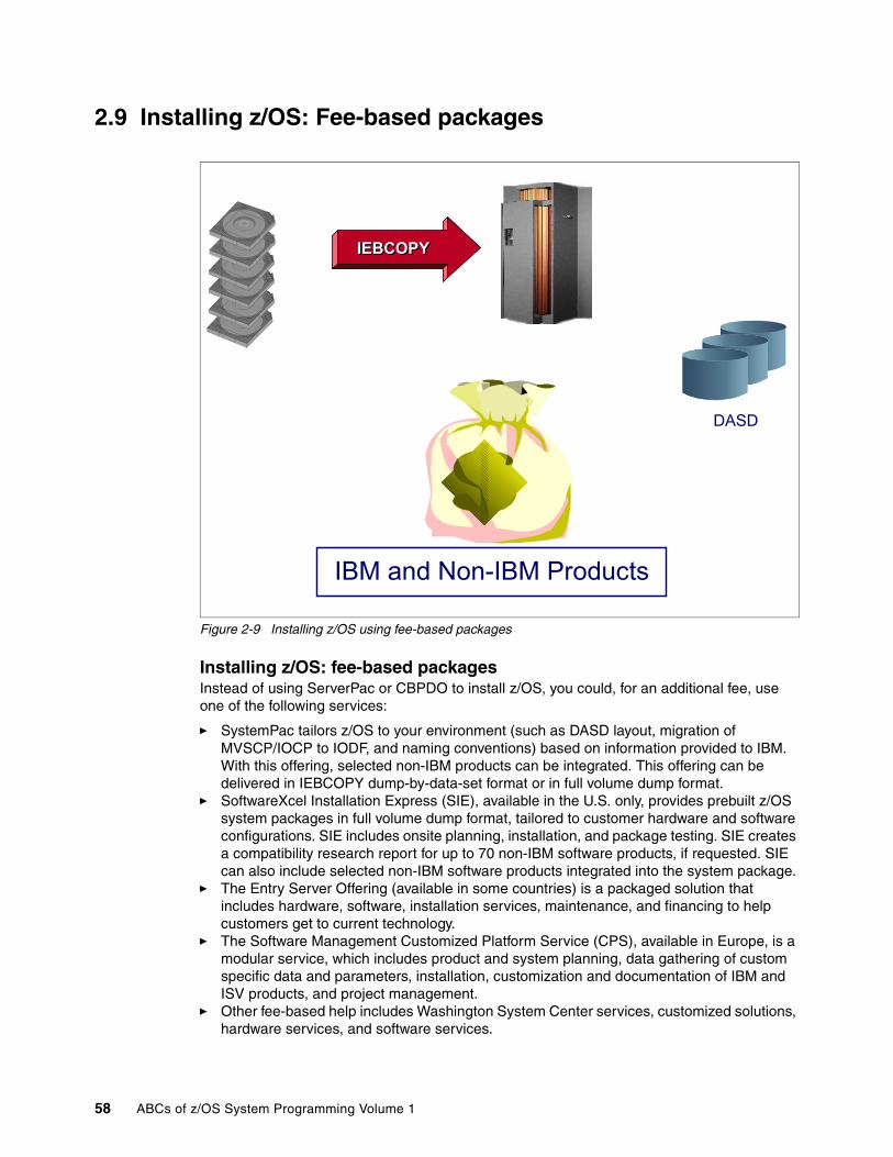
2.9 Installing z/OS: Fee-based packages
Figure 2-9 Installing z/OS using fee-based packages
Installing z/OS: fee-based packagesInstead of using ServerPac or CBPDO to install z/OS, you could, for an additional fee, use one of the following services:
� SystemPac tailors z/OS to your environment (such as DASD layout, migration of MVSCP/IOCP to IODF, and naming conventions) based on information provided to IBM. With this offering, selected non-IBM products can be integrated. This offering can be delivered in IEBCOPY dump-by-data-set format or in full volume dump format.
� SoftwareXcel Installation Express (SIE), available in the U.S. only, provides prebuilt z/OS system packages in full volume dump format, tailored to customer hardware and software configurations. SIE includes onsite planning, installation, and package testing. SIE creates a compatibility research report for up to 70 non-IBM software products, if requested. SIE can also include selected non-IBM software products integrated into the system package.
� The Entry Server Offering (available in some countries) is a packaged solution that includes hardware, software, installation services, maintenance, and financing to help customers get to current technology.
� The Software Management Customized Platform Service (CPS), available in Europe, is a modular service, which includes product and system planning, data gathering of custom specific data and parameters, installation, customization and documentation of IBM and ISV products, and project management.
� Other fee-based help includes Washington System Center services, customized solutions, hardware services, and software services.
IEBCOPYIEBCOPY
DASD
IBM and Non-IBM Products
58 ABCs of z/OS System Programming Volume 1

Chapter 3. z/OS storage concepts
This chapter describes basic z/OS storage concepts, including:
� Virtual storage and address spaces
� How processor storage is managed by z/OS
� How virtual storage in managed by z/OS
� Address space map for 31-bit and 64-bit
� System address spaces
� Dynamic address translation
� Residence Mode and Addressing Mode
� Subsystem definitions
� Multiprogramming and multitask
� Module object and load module
� Memory hierarchies
For more detailed information about virtual storage concepts, refer to ABCs of z/OS System Programming Volume 10.
3
© Copyright IBM Corp. 2008. All rights reserved. 59

3.1 Processor storage overview
Figure 3-1 Overview of processor storage
Processor storage overviewFrom 370-XA until ESA/390 (“old” mainframe architecture), processor storage consisted of central storage plus expanded storage.
The technology of central storage has the following characteristics:
� It is made of Silicium.� The processor is directly accessible (for programs and data).� It is volatile, fast, and expensive, when compared with magnetic storage (DASD, tape).
Expanded storage (with the same technology of central storage) provided a way to relieve the performance constraint imposed by the 31-bit real address size in a logical partition that limited central storage to 2 GB. Expanded storage served as a high-speed backing store for paging and for large data buffers.
In z/Architecture, there is no expanded storage because the 31-bit real address limitation is relieved to a 64-bit real address (up to 16 Exa real addresses). However, the largest mainframe (the z9 CEC) only has a total central storage capacity of 512 GB.
Note: The terms central storage, main storage, real storage, and memory always refer to physical memory, which is the one that resides within the processor cage and is made of Silicium.
Processing Unit
CentralStorage
ExpandedStorage
AUXILIARY
Processing Unit
CentralStorage
AUXILIARY
ESA/390
z/OS
60 ABCs of z/OS System Programming Volume 1
The system initialization process begins when the system operator selects the LOAD function at the system console. This causes an initial program load (IPL), which is equivalent to a boot in other platforms. z/OS locates all of the usable central storage that is online and available in the IPLed logical partition, creating a virtual storage environment for the building of various system areas. z/OS uses central storage to map the virtual storage, which implies allocating and using auxiliary storage.
Next, we describe central storage and auxiliary storage properties.
� Central storage
Central storage, also referred to as main storage, provides the system with a volatile processor that is directly addressable, with fast access for the electronic storage of data.
Because of the volatile property of central storage, modern mainframes have an Internal Battery Feature (IBF) that keeps central storage running so operators can perform normal shutdown procedures in power failure situations.
Both data and programs must be loaded into central storage (from magnetic devices such as disks and tapes) before they can be processed by the processors. The maximum central storage size per logical partition is restricted by hardware and the z/OS and system architecture, as follows:
– In System/370 architecture, the maximum is 16 MB.– From S/370™-XA architecture to ESA/390 architecture, the maximum is 2 GB. – In z/Architecture, the maximum is 16 EX (exabytes). From z/OS V1R8 and up, the limit
is 4 TB.
Keep in mind, however, that the maximum central storage size in a z9 CEC is 512 GB.
� Auxiliary storage
Auxiliary storage consists of z/OS paging data sets (files) located in direct access storage devices (DASD). Note that DASD in mainframe terminology is referred to as “disk” on other platforms. DASD is a non-volatile magnetic memory made of iron oxide. Paging data sets are used to implement virtual storage, which contain the paged-out portions of all virtual storage address spaces. In addition, output to virtual I/O (VIO) devices may be also stored in the paging data sets. The concept of address spaces is covered in 3.2, “Virtual storage concepts” on page 62. The concept of VIO is covered in 3.9, “Auxiliary Storage Manager” on page 70.
Processing unit Along with storage, Figure 3-1 on page 60 depicts a processing unit (PU). The processing unit is the hardware in charge of executing instructions located in central storage. The PU contains the sequencing and processing facilities for instruction execution, interruption action, timing functions, initial program loading and other machine-related functions. PUs and central storage are packed in units known as “books” within the CEC cage in a z9 machine.
Chapter 3. z/OS storage concepts 61

3.2 Virtual storage concepts
Figure 3-2 Virtual storage, auxiliary storage
Virtual storage conceptsVirtual storage is an illusion created by z/Architecture together with z/OS, such that the program seems to have more central storage that it really has. The virtual storage concept was introduced in the Atlas System used for the first time in the IBM System/370 architecture. The virtual storage concept is based on the following points:
� An address (called virtual) as referred by a program is an identifier of a required piece of information in central storage. This allows the size of an address space (all virtual addresses available to a program) to exceed the central storage size.
� All central storage references are made in terms of virtual storage address.
� A hardware mechanism (DAT) is employed to perform a mapping between the virtual storage address and its physical location in central storage.
� When a requested address is not in central storage (that is, there are more virtual addresses than bytes in central storage), an interruption is signaled and the required data is brought into memory.
In z/OS, virtual storage is implemented (transparently to the program) using the concepts of:
Segment Program address space is divided into segments of 1 M addresses in size.
Page A segment is divided into pages, which are blocks of 4 K addresses in size.
Central Storage
4k
User A address space
User X address space
10254000Virtual address
10254000Virtual address
abc
xyx00971000Real address
0014A000Real address
Page data sets
62 ABCs of z/OS System Programming Volume 1

Frame Central storage is divided into frames, which are blocks of 4 Kbytes in size.
Slots Auxiliary storage page data sets are formatted in slots, which are blocks of 4 Kbytes in size.
Dynamic address translation (DAT) This is implemented by hardware and by software throughout page tables and segment tables.
A z/OS program accesses addresses located in virtual storage. Only pages of the program currently active need to be in a central storage frame at processing time. The inactive pages are held in auxiliary storage.
Chapter 3. z/OS storage concepts 63

3.3 Frames, slots, and pages
Figure 3-3 Storage frames, slots, and pages
Frames, slots, and pagesWhen a program is selected, z/OS brings it into virtual storage (allowing it to use a range of virtual addresses) and divides it into pages of 4 K addresses. Then, z/OS transfers the pages of the program into central storage for execution and out to auxiliary storage when not needed and central storage is under contention.
Actually, not all pages of a program are necessarily in central storage at one time. To the programmer the entire program appears to occupy a contiguous space of addresses in central storage at all times. The pages that are in central storage, however, do not necessarily occupy contiguous space.
The parts of a program executing in virtual storage must be moved between real and auxiliary storage. To allow this, z/OS breaks the storage into blocks of 4 K, as explained here:
� A block of 4 KB of central storage is a frame.
� A block of 4 K addresses in virtual storage is a page. A virtual storage is backed by:
– Central storage
– Auxiliary storage
� A block of storage on an auxiliary device is a slot.
Frames, pages, and slots are all the same size (4 K).
VIRTUAL
PAGES
E F G H
A B C D
CENTRAL
A
FRAMES
F
D G E
AUXILIARY
SLOTS
B C
D G
64 ABCs of z/OS System Programming Volume 1

3.4 The address space concept
Figure 3-4 Address space concept
The address space conceptThe System/370 was the first IBM architecture to use virtual storage and address space concepts emulating the first virtual system, the Atlas. The address space is a set of contiguous virtual addresses available to a program instructions and its data. The range of virtual addresses available to a program starts at 0 and can go to the highest address permitted by the operating system architecture. The address space size is decided by the length of the fields that keeps such addresses. Because it maps all of the available addresses, an address space includes system code and data as well as user code and data. Thus, not all of the mapped addresses are available for user code and data. The S/370 architecture used 24 bits for addressing. So, the highest accessible address in the MVS/370 was 16 megabytes, which was also the address space size.
With MVS/XA™, the XA architecture extended to 31 bits for addressing and the address space size went from 16 MB to 2 GB, which is 128 times bigger. The 16 MB address became the division point between the two architectures and is commonly called the line.
For compatibility, programs running in MVS/370 should run in MVS/XA, and new programs should be able to exploit the new technology. So, the high-order bit of the address (4 bytes) is not used for addressing, but rather to indicate to the hardware how many bits are used to solve an address: 31 bits (bit 32 on) or 24 bits (bit 32 off).
With z/OS, the z/Architecture extended to 64 bits and the address space size went from 2 GB to 16 Exa, which is 8 giga times bigger. The 2 G address is called the bar. The addresses above the bar are used for data only.
16 M (line)
16 Exa 2
64 bits
0
user & z/OS
programs
user & z/OS data
user & z/OS data
user & z/OS
programslocate mode
2 31
2 G (bar)
64
Chapter 3. z/OS storage concepts 65

3.5 Addressing mode and residence mode
Figure 3-5 Addressing mode and residence mode
Addressing mode and residence modeWith the MVS/XA came the concept of addressing mode (AMODE). AMODE is a program attribute to indicate which hardware addressing mode should be active to solve an address; that is, how many bits should be used for solving and dealing with addresses.
� AMODE=24: Indicates that the program may address up to 16 M virtual addresses.� AMODE= 31: Indicates that the program may address up to 2 G virtual addresses.� AMODE= 64: Indicates that the program may address up to 16-Exa virtual addresses
(only in z/Architecture).
The concept of residence mode (RMODE) is used to indicate where a program should be placed in the virtual storage (by z/OS program management) when the system loads it from DASD, as explained here:
� RMODE=24: Indicates that the module must reside below the 16 MB virtual storage line. Among the reasons for RMODE24 is that the program is AMODE24, the program has control blocks that must reside below the line.
� RMODE= ANY: Indicates that the module may reside anywhere in virtual storage, but preferentially above the 16 MB virtual storage line. Because of this, such an RMODE is also called RMODE 31. Note that in z/OS, there is no RMODE=64, because the virtual storage above 2 G is not suitable for programs, only data.
AMODE and RMODE are load module attributes assigned when load modules are created by the Binder program and are placed in load module’s directory entry in a partitioned data set.
Program B: 000C3850
16 M line
16 Hexa 64
bits
0
programA data
data
program A
AMODE 31
RMODE 24
RMODE ANY
program B 24 bitsAMODE 24
address150C3850
Program A: 150C3850
22 G bar
66 ABCs of z/OS System Programming Volume 1

3.6 Storage managers
Figure 3-6 The storage component managers
Storage managersIn a z/OS system, storage is managed by the following z/OS components:
� Virtual Storage Manager™ (VSM): Virtual storage is managed by the Virtual Storage Manager (VSM). The main function of VSM is to control the use of virtual storage addresses by programs. Each installation can use virtual storage parameters (at data set Sys1.Parmlib) to specify how certain virtual storage areas are to be allocated to programs. These parameters have an impact on central storage use and overall system performance.
� Real Storage Manager (RSM™): Controls the allocation of central storage frames to pages during system initialization, and during system execution.
� Auxiliary Storage Manager (ASM): Controls the use of page data sets and the implicit paging I/O operation. As a system programmer, you are responsible for the size and the performance of the page data sets.
VSMVSM
RSMRSM
ASMASM
VirtualStorageManager
RealStorageManager
AuxiliaryStorageManager
Chapter 3. z/OS storage concepts 67

3.7 Virtual Storage Manager
Figure 3-7 Virtual Storage Manager
Virtual Storage Manager (VSM)VSM is the z/OS component that manages virtual storage. Its main function is to control the use of virtual storage addresses. Virtual storage allows you to write large programs without the need for complex overlay structures.
The existence of an address space does not imply that all virtual addresses are automatically available to programs. Virtual storage addresses must be requested by programs through the use of the GETMAIN or STORAGE OBTAIN macros and returned to the Virtual Storage Manager using the FREEMAIN or STORAGE RELEASE macro. The VSM functions are:
� Allocate and release blocks of virtual storage on request by programs.� Ensure that central storage frames exist for naturally fixed pages as SQA, LSQA, CSA. � Associate a storage protection key with each virtual storage block requested. This function
is provided through the GETMAIN and STORAGE macros. Refer to ABCs of z/OS System Programming Volume 10 for more information about storage protection.
� Maintain storage use information by generating SMF records.
VSM also provides services that are especially useful when determining available storage, coding recovery procedures, or specifying areas to be included in a dump, as listed here:
� VSMREGN macro: List the starting address and the size of the private area regions associated with a given program (task).
� VSMLOC macro: Verify that a given area has been allocated through a GETMAIN or STORAGE macro.
� VSMLIST macro: List the ranges of virtual storage allocated in a specified area.
VIRTUALVIRTUAL
STORAGESTORAGE
MANAGERMANAGER
CONTROLSALLOCATION/
DEALLOCATIONOF
VIRTUAL STORAGE
MAINTAINSSTORAGE USEINFORMATION
FOR SMF
68 ABCs of z/OS System Programming Volume 1

3.8 Real Storage Manager
Figure 3-8 Real Storage Manager
Real Storage Manager (RSM)RSM is the z/OS component that controls the usage of central storage frames. RSM acts together with the Auxiliary Storage Manager (ASM) to support the virtual storage concept, and with VSM to ensure that a GETMAINed page is backed up in a central storage frame. Furthermore, RSM establishes many services to other components and application programs to manipulate the status of pages and frames. Some RSM functions are:
� Allocate frames for pages located in slots during page-in operations.
� Allocate central storage for page fixing. Fixing a page in a frame means that the page never will stolen from central storage even if there is a lack of frames. The reason justifying such function is availability, not performance.
� Allocate frames to satisfy GETMAIN requests for SQA, LSQA, CSA (pages naturally fixed).
� Build segment and page tables. These tables are used to translate a virtual address to a to real address.
� Work with WLM in page swapping, page stealing and the unreferenced interval count (UIC) calculation process.
MANAGES THE USEOF CENTRAL STORAGE
RESOURCE
DIRECTS MOVEMENT OF PAGES BETWEEN
CENTRAL AND AUXILIARY
BUILDSSEGMENT AND PAGE TABLES
REALREAL
STORAGESTORAGE
MANAGERMANAGER
Chapter 3. z/OS storage concepts 69

3.9 Auxiliary Storage Manager
Figure 3-9 Auxiliary Storage Manager
Auxiliary Storage Manager (ASM)ASM is a z/OS component responsible for transferring virtual pages between central frames and auxiliary storage slots (page data sets). This is done as either a paging operation (one page at time) or as a physical swapping operation (an address space, all pages at a time). ASM manages the transfer by initiating the I/O and by maintaining tables to reflect the current status of the slots. This status includes the location of each page in each slots.
To page efficiently and expediently, ASM divides the pages into classes, namely PLPA, common, and local. There is at least one page data set for each class. Contention is reduced when these classes of pages are placed on different physical devices. In addition, output to virtual I/O (VIO) devices may be stored in local paging data sets. VIO are user temporary data sets allocated in central and auxiliary storage. Page data sets are created and formatted by the system programmer through the DEFINE IDCAMS command.
ASM attempts to maximize page I/O efficiency by incorporating a set of algorithms to distribute the I/O load evenly (through the local page data sets). In addition, every effort is made to keep the system operable in situations where a shortage of a specific type of slots exists. ASM selects a local page data set for page-out from its available page data sets. ASM selects these data sets in a circular order within each type of data set, subject to the availability of free space and the device response time. If the address space is physically swapped out directly from central storage to auxiliary storage, ASM reads and writes these working set pages in parallel. Since z/OS V1R8, there is no more physical swapping; refer to 3.10, “Paging and swapping” on page 71 for more information.
MANAGERSYSTEM DASDFOR PAGING
AND SWAPPING
AUXILIARYAUXILIARY
STORAGESTORAGE
MANAGERMANAGERTRANSFERS PAGES
BETWEEN CENTRAL AND AUXILIARY
FOR PAGINGAND SWAPPING
70 ABCs of z/OS System Programming Volume 1

3.10 Paging and swapping
Figure 3-10 Paging and swapping concepts
Paging and swappingPaging is the movement of pages between central storage frames and auxiliary storage slots.
There are two types of paging operations:
� Page-in, which flows from a slot to a frame. It is caused by a page fault. A page fault is an interrupt caused by the hardware in charge of translating a virtual address into a real address. The page fault happens because the page is not currently mapped to a frame. RSM gains control and, through ASM, provides a page-in operation to retrieve the page from auxiliary storage.
� Page-out, which flows from a frame to a slot. It is caused when a changed page needs to be stolen from central storage because this memory is under contention. RSM calls ASM to schedule the paging I/O necessary to send these pages to auxiliary storage.
Swapping is the primary function used by WLM (a z/OS component in charge of performance) to exercise control over the distribution of resources and system throughput. One reason for swapping is, for example, pageable storage shortages. There are two types of swapping:
� Physical swapping: Transferring all pages in an address space between central storage and auxiliary storage.
– A physical swapped-in address space is an active one (its programs can be executed) that has pages in central storage and pages in auxiliary storage.
TRANSFERRING PAGESIN AND OUT OF CENTRAL STORAGE
ONE PAGE
AT A TIME(PAGING)
A SET OF PAGES FROM THE
SAME ADDRESS
SPACE, AT A TIME
(SWAPPING)
Chapter 3. z/OS storage concepts 71

– A physical swapped-out address space is an inactive one having all pages in auxiliary storage, so it cannot execute its programs until it is swapped-in.
� Logical swapping: To reduce the processor and channel subsystem overhead involved during a physical swap needing to access auxiliary storage, WLM performs logical swaps where possible.
In a logical swap, LSQA fixed frames and recently referenced frames are kept in central storage (in contrast to physical swaps, where these frames are moved to auxiliary storage). Address spaces that are swapped for wait state conditions are the best candidates for logical swaps. Since z/OS 1.8, all swaps are logical.
72 ABCs of z/OS System Programming Volume 1

3.11 Auxiliary page data sets
Figure 3-11 Paging to auxiliary data sets
Auxiliary page data setsAuxiliary page data sets are formatted in slots; they should contain pages that for some reason should not stay in central storage frames. As mentioned, ASM divides the pages of the system into classes: private, CSA, and PLPA. Based on these classes, there are three types of page data sets.
� PLPA page data set: This unique and required page data set contains pageable link pack area pages. Refer to “Link pack area (LPA and Extended LPA)” on page 79 for more information about this topic.
� Common page data set: This unique and required page data set contains the CSA non-fixed virtual pages of the system common area. Refer to “Common service area (CSA and Extended CSA)” on page 78 for more information about this topic.
� Local page data sets: These contain the private area pages of all address space pages, data spaces, and any VIO data sets. To better distribute the paging activity load on different volumes and controllers, you can have several local page data sets.
Also, peaks in central storage demand may occur during system operation, resulting in heavy use of local page data set slots. To address this situation, local page data sets can be dynamically added to and deleted from the paging configuration without re-IPLing the system.
EXTENDEDPRIVATE
PRIVATE
ECSA
EPLPA
ESQA
NUCLEUS
SQA
PLPA
CSACommon
Page Data Set
PLPA Page Data Set
LOCAL Page Data
Sets
16 M line
2 G bar
Chapter 3. z/OS storage concepts 73

3.12 31-bit address space map
Figure 3-12 31-bit address space map
31-bit address space mapSince the introduction of /XA architecture, the address space size is 2 G addresses because the fields keeping the virtual addresses are 31 bits in size. (Refer to “64-bit address space map” on page 85 for information about the 64-bit address space map.)
The virtual address space is divided into areas (sets of addresses) according to their use. Virtual storage allocated in each address space is divided between system requirements and user requirements. z/OS itself requires space from each of the basic areas. Each virtual address space consists of:
� The common area below 16 M addresses
� The private area below 16 M addresses
� The extended common area above 16 M addresses
� The extended private area above 16 M addresses
For more information about common areas and private areas, refer to 3.13, “The common virtual storage area” on page 75.
Most of z/OS areas exist both below and above 16 M, providing an environment that can support both 24-bit and 31-bit addressing. However, each area and its counterpart above 16 M can be thought of as a single logical area in virtual storage.
2 GB
0
16 MB
16M
Extended Private
ELSQA/ESWA/229/230/249
Extended User Region
Extended Common
Common
Private
Common
Extended CSA
Extended PLPA/FLPA/MLPA
Extended SQAExtended Nucleus
NucleusSQA
PLPA/FLPA/MLPACSA
LSQA/SWA/229/230/249
User Region
System Region
PSA
20KB
4KB
74 ABCs of z/OS System Programming Volume 1

3.13 The common virtual storage area
Figure 3-13 Common storage area
The common virtual storage areaThe z/OS implementation of virtual storage is to have one address space per set of related programs (like a job step). The advantage of this design is isolation; any error is contained in one address space and cannot be propagated to another address space. Also, because the number of address spaces can be large, the number of virtual addresses to be used by programs is enormous. However, such a design poses a problem: the need for communication between programs from different address spaces. To solve that problem, the common area was introduced. All address spaces in a z/OS system image share a virtual storage area known as the common area. That means that all address spaces programs in this z/OS access the same common data and the same common programs, with the same virtual address. The common area is created at IPL (boot) time by z/OS.The following virtual storage areas are located in the common area:
� Prefixed storage area (PSA) with 8 K in z/Architecture � Common service area (CSA)� Link pack areas: Pageable (PLPA), Fixed (FLPA), and Modified (MLPA)� System queue area (SQA)� Nucleus
Each storage area in the common area (below 16 M) has a counterpart in the extended common area (above 16 M), except the PSA. The CSA and SQA sizes are settled during the IPL, according to system initialization parameters in the SYS1.PARMLIB (IEASYSxx) system data set.
COMMON
PRIVATE
PRIVATE
COMMON
PRIVATE
PRIVATE
COMMON
PRIVATE
PRIVATE
COMMON
PRIVATE
PRIVATE
COMMON
PRIVATE
PRIVATE
16 M
2 G
0PRIVATE
COMMON
EXTENDED PRIVATE
EXTENDED COMMON
Chapter 3. z/OS storage concepts 75

3.14 z/OS nucleus
Figure 3-14 z/OS nucleus
z/OS nucleusThe nucleus in the common area contains the z/OS nucleus programs (kernel) and extensions to the nucleus that are initialized during IPL processing. The nucleus contains the most important z/OS programs. The nucleus RMODE24 programs reside below the 16 M line. The nucleus RMODE31 programs reside above the 16 M line.
The program modules that are to be added to the nucleus area must reside as members in the SYS1.NUCLEUS data set. During the IPL process, the operator points to the device number (0250, in the example shown in Figure 3-14) of the volume containing that data set, causing the copy of the programs to be stored in memory. The system programmer can add or delete modules from the nucleus by simply specifying the members on INCLUDE or EXCLUDE statements in the data set SYS1.PARMLIB, at member NUCLSTxx.
The nucleus is always fixed in central storage; that is, no pages from the nucleus can be stolen to page data sets slots.
IEANC250
IEANS002
IEANS001
IEANUC01
OTHER
MODULES
(Device Number=0250)
SYS1.NUCLEUS
16 M
16M
PRIVATE
PRIVATE
ECSA
ELPA
ESQA
NUCLEUS
SQA
LPAs
CSA
76 ABCs of z/OS System Programming Volume 1

3.15 System queue area (SQA/ESQA)
Figure 3-15 System queue area (SQA and ESQA)
System queue area (SQA/ESQA)The system queue area (SQA) is a getmainable common area containing control blocks used by z/OS to manage transaction workloads and the use of system resources. It is a sort of virtual storage reserved area for future getmains/freemains issued by authorized z/OS and non- z/OS programs. The number of active address spaces (which depends on the workload executed in the system) affects the system's use of SQA.
SQA is allocated directly below the nucleus. Extended SQA (ESQA) is allocated directly above the extended nucleus. Both allocations occur at IPL time. The size of SQA can be specified through the SQA parameter in the IEASYSxx member of SYS1.PARMLIB, or like any IEASYSxx parameter, through the operator in a z/OS console at IPL.
When a getmain for SQA/ESQA cannot be fulfilled because SQA/ESQA is full, then the SQA/ESQA overflows to CSA/ECSA. When SQA/ESQA pages are in use (getmained), they are fixed in central storage.
Ensuring the appropriate size of SQA/ESQA and CSA/ECSA is critical to the long-term operation of z/OS. If an occupancy threshold is crossed, z/OS takes the following actions, trying to avoid an unprogrammed IPL:
� Message IRA100E displays in the z/OS console.
� No new address spaces are created.
� No new jobs are selected by initiators.
16M
PRIVATE
16 M
PRIVATE
ECSA
ELPA
ESQA
NUCLEUS
SQA
LPA
CSA
System Tables and Control Blocks
Chapter 3. z/OS storage concepts 77

3.16 Common service area (CSA and Extended CSA)
Figure 3-16 Common service area (CSA and ECSA)
Common service area (CSA and Extended CSA)The common service area is a getmainable common area containing control blocks used by subsystem programs such as JES2, DFSMS, and RACF, and access methods like VSAM. It is a sort of virtual storage reserved area for future getmains/freemains issued by such programs.
CSA/ECSA normally contains data referenced by a number of system address spaces, enabling address spaces to communicate by referencing the same piece of CSA data. In a sense, CSA/ECSA looks like SQA/ESQA.
CSA is allocated directly below the MLPA. ECSA is allocated directly above the extended MLPA. If the virtual SQA/ESQA space is full, z/OS allocates additional SQA/ESQA space from the CSA/ECSA.
The size of the CSA/ECSA can be specified through the CSA parameter in the IEASYSxx member of SYS1.PARMLIB, or like any IEASYSxx parameter, through the operator in a z/OS console at IPL. The common service area (CSA) contains pageable and fixed data areas that are addressable by all active virtual storage address spaces.
16M
PRIVATE
16 M
PRIVATE
ECSA
ELPAs
ESQA
NUCLEUS
SQA
LPAs
CSA
SYSTEMAND USER WORK AREAS
78 ABCs of z/OS System Programming Volume 1

3.17 Link pack area (LPA and Extended LPA)
Figure 3-17 Link pack area (LPA and ELPA)
Link pack area (LPA and Extended LPA)The link pack area contains programs that are preloaded at IPL time in the common area, from the SYS1.LPALIB data set. These programs can be certain z/OS SVC routines, access methods code, other read-only z/OS programs (the ones not modified along its execution), and any read-only reenterable user programs selected by an installation.
Because such code is in the common area, all these single copy programs can be executed in any address space. Their copy is not self-modifying (reentrant), meaning that the same copy of the module can be used by any number of tasks in any number of address spaces at the same time. This reduces the demand for central storage and lowers the program fetch overhead.
The LPA/ELPA size depends on the number of modules loaded in it. When modules are added to LPA, the growth in LPA can cause the common area to cross one or more segment (1 M) boundaries. This reduces the available private area for all address spaces, even for those address spaces not using the load modules added to LPA.
All modules placed in LPA are assumed to be APF-authorized. Being APF-authorized means that a program can invoke any SVC routine which accesses protected system and private areas. Although LPA boundaries cannot be changed after IPL, it is possible to dynamically include new load modules to LPA without an IPL. In this case, z/OS issues a Getmain from CSA/ECSA and uses such virtual storage area to load the load module.
16M
PRIVATE
16 M
PRIVATE
ECSA
ELPA
ESQA
NUCLEUS
SQA
LPA
CSA
Load Modules
Chapter 3. z/OS storage concepts 79

The RMODE attribute of the program (load module) decides its location (that is, LPA or ELPA). The extended link pack area (ELPA) is built above 16 M.
The LPA is divided into:
� Pageable LPA (PLPA/EPLPA): In this area, page faults (the page is not mapped in a central storage frame) may occur.
� Fixed LPA (FLPA/EFLPA): This area is used for modules that have to be fixed in memory, instead of pageable. The modules to be fixed are specified in system initialization parameters.
� Modified LPA (MLPA and EMLPA): The MLPA can be used at IPL time to temporarily modify or update the PLPA with new or replacement modules.
Pages from modules (programs) placed anywhere in LPA are always in virtual storage. Pages from modules placed in FLPA are also always in central storage. Whether modules that are in LPA, but outside FLPA, are in central storage depends on how often they are used by all the programs of the system, and on how much central storage is available. The more often an LPA module is used, and the more central storage that is available on the system, the more likely it is that the pages containing the copy of the module will be in central storage at any given time.
Each address space uses the same common area. Portions of the common area are paged in and out as the demands of the system change and as new user jobs (batch or time-shared) start and old ones terminate.
80 ABCs of z/OS System Programming Volume 1

3.18 31-bit address space private area
Figure 3-18 The user’s private area (user region)
31-bit address space private areaThere are two private areas: below the 16 M line (PVT), and above the 16 M line (EPVT). Their size is the complement of the common area’s size. The virtual addresses within the private area is unique to the programs running in such areas.
The private area is formed by the following areas:
� Subpools 229, 230, and 249
This area allows private storage to be obtained in the requestor's storage protect key. The area is used for control blocks that can be obtained only by authorized programs (as z/OS) having appropriate storage protect keys.
A subpool is a virtual storage area with the same properties regarding storage key, pageable or fixed, private or common, fetch protected or not, and so on. When a program Getmains virtual storage addresses, it must indicate the subpool number.
� Local System Queue Area (LSQA)
This area contains tables and control blocks queues associated with the address space. LSQA is intermixed with SWA and subpools 229, 230, and 249 downward from the bottom of the CSA into the unallocated portion of the private area, as needed.
ELSQA is also intermixed, but is allocated downward from 2G into the unallocated portion of the extended private area, as needed. LSQA does not take space below the top of the highest storage currently allocated to the user region.
2 G
0
16 M
Extended Private
ELSQA/ESWA/229/230/249
Extended User Region
Extended Common
Common
Private
Common
LSQA/SWA/229/230/249
User Region
System Region
PSA
20 K4 K
Chapter 3. z/OS storage concepts 81

� Scheduler Work Area (SWA
This area contains control blocks that exist from task initiation to task termination. It includes control blocks and tables created during JCL interpretation.
� A 16 K system region area
� User region
This region is used for running user program applications (loaded at subpools 251/252) and storing user program data (subpools from 0 to 127).
When a module is loaded into the private area for an address space, the region available for other components is reduced by the amount of storage used for the module. The amount of private virtual storage that a job can use for subpools 251/252 and from 0 to 127 (the low addresses of the two private areas) may be limited through the REGION keyword on the JOB or EXEC Job Control Language (JCL) statements. Also, the region size can be controlled and overridden through the SMF exit IEFUSI. A value equal to 0 K or 0 M gives the job all private storage available.
82 ABCs of z/OS System Programming Volume 1

3.19 Data spaces and hiperspace
Figure 3-19 Data space management
Data spaces and hiperspaceThe growth of processing, storage, and I/O capabilities led to a virtual storage constraint. The upward growth in virtual storage (address space size) was limited by the architecture (hardware and software).
ESA/370 and MVS/ESA™ came to relieve virtual storage constraint, bringing horizontal growth to virtual storage with data space, a new type of z/OS address space, as well as hiperspace, a new type of service.
Data space is a type of virtual storage space with a range up to 2 GB of contiguous virtual storage. The virtual storage map of a data space is quite different; that is, the entire 2 GB is available for user data and does not contain specific areas as an address space. A data space can hold only data (operands accessed by instructions located in address spaces); it does not contain z/OS control blocks or programs in execution. Program code does not execute in a data space, although a program can reside in a data space as data (to be executed, however, it needs to be copied to an address space). A program can refer to data in a data space at bit level, as it does in a work file.
A program references data in a data space directly, in much the same way as it references data in an address space. It addresses the data by the bit, manipulating, comparing, and performing arithmetic operations. The program uses the same instructions (such as load, compare, add, and move character) that it would use to access data in its own address space. Before accessing data in a data space, a program must change the processor access mode; that is, it must use special assembler instructions to change its access mode.
DATASPACE
DATASPACE
EXPANDEDSTORAGE
CENTRALSTORAGE
ADDRESSSPACE
AUXILIARYSTORAGE
HIPERSPACE
HIPERSPACE
z/Architecture
ESA/390 architecture
Chapter 3. z/OS storage concepts 83

High performance data access, known as hiperspace, is a kind of data space created with the same RSM services used to create a data space. It provides the applications an opportunity to use expanded storage as a substitute to I/O operations. Hiperspaces differ from data spaces in the following ways:
� Main storage is never used to back the virtual pages in hiperspace, whose pages are located in expanded or auxiliary.
� Data can be retrieved and stored between a hiperspace and a data space only using MVS services. This avoids the complex programming required when accessing data in a data space.
� Data is addressed and referred to as a 4 K block.
Although z/OS do not support Expanded Storage when running under the z/Architecture, hiperspace continues to operate in a compatible manner, that is, a hiperspace is now mapped in central storage (instead of expanded) and auxiliary storage.
Programs can use data spaces and hiperspaces as described here:
� To obtain more virtual storage than a single address space gives a user.
� To isolate data from other tasks (programs) in the address space. Data in an address space is accessible to all programs executing in that address space. You might want to move some data to a database or hiperspace for security or integrity reasons. You can restrict access to data in those spaces to one or several units of work.
� To share data among programs that are executing in the same address space, or different address spaces. Instead of keeping the shared data in common areas, you can create a database or hiperspace for the data you want your programs to share. Use this space as a way to separate your data logically by its own particular use.
� To provide an area in which to map a data-in virtual object.
84 ABCs of z/OS System Programming Volume 1

3.20 64-bit address space map
Figure 3-20 64-bit address space map
64-bit address space mapAs previously mentioned, z/Architecture broke the 2 GB (31-bit) central storage limit and the 2 G (31-bit) address limit, and moved the limit to 16 Exa (64-bit).
The maximum of a z/OS address space is 16 Exa addresses, which makes the new address space 8 billion times the size of the former 2 G address space. However, any new created address space in z/OS is initialized with 2 G addresses (as it was previously), but with the potential to go beyond.
For compatibility, the layout of the virtual storage areas for an address space is the same below 2 G. The area that separates the virtual storage area below the 2 G address from the user private area is called the bar, as shown in Figure 3-20, and is 2 G addresses thick. In a 64-bit virtual storage environment, the terms “above the bar” and “below the bar” are used to identify the areas between 2**31 and 2**64-1, and 0 and 2**31-1, respectively.
For example, a address in the range 0 to 7FFFFFFF is below the bar. An address in the range FFFFFFFF to 7FFFFFFF_FFFFFFFF is above the bar. This is basically an alteration to the 2 G 31-bit terminology that related “below the line” to 24-bit storage, and “above the line” to 31-bit addresses.
The 64-bit address space map is:
� 0 to 2**31: The layout is the same; see Figure 3-12 on page 74.
User Private area
Area Reserved for Memory Sharing
User Private area
Below 2GB0
642
532502
412
322312
16M Line
The Bar
Chapter 3. z/OS storage concepts 85

� 2**31 to 2**32: From 2 GB to 4 GB is considered the bar. Below the bar can be addressed with a 31-bit address. Above the bar requires a 64-bit address.
Just as the system does not back the page at 7FFFF000 in order to protect programs from addresses which can wrap to 0, the system does not back the virtual area between 2 GB and 4 GB. That means a 31-bit address with the high bit on will always program check if used in AMODE 64.
� 2**31 - 2**41: The Low Non-shared area starts at 4G and goes to 2**41.
� 2**41 - 2**50: The Shared Area starts at 2**41 and goes to 2**50 or higher if requested (up to 2 **53).
� 2**50 - 2**64: The High Non-shared area starts at 2**50 or wherever the Shared Area ends and goes to 2**64.
The shared area may be shared between programs running in private areas from specific address spaces. In contrast, the below the bar common area is shared between all address spaces.
The area above the bar is designed to keep data (such as DB2 buffer pool and WebSphere data), and not to load modules (programs). There is no RMODE64 as a load module attribute. However, such programs running below the bar may request virtual storage above the bar and access it. In order to access such an address, the program must be AMODE64.
To allocate and release virtual storage above 2 G, a program must use the services provided in the IARV64 macro. The GETMAIN, FREEMAN, STORAGE, and CPOOL macros do not allocate storage above the 2 G address, nor do callable cell pool services.
User private areaThe area above the bar is intended for application data; no programs run above the bar. No system information or system control blocks exist above the bar, either. Currently there is no common area above the bar.
The user private area, as shown in Figure 3-20 on page 85, includes:
� Low private: The private area below the line
� Extended private: The private area above the line
� Low Non-shared: The private area just above the bar
� High Non-shared: The private area above Shared Area
As users allocate private storage above the bar, it will first be allocated from the Low Non-shared area. Similarly, as the Shared Area is allocated, it will be allocated from the bottom up. This is done to allow applications to have both private and shared memory above the bar, and avoid additional machine cycles to perform dynamic address translation (DAT).
For virtual storage above the bar, a new JCL keyword (MEMLIMIT) is introduced on the JOB and EXEC JCL statements. For virtual storage above the bar, there is no practical limit to the amount of virtual address range that an address space can request. However, there are practical limits to the central storage and auxiliary storage needed to back the request. Therefore, a limit is placed on the amount of usable virtual storage above the bar that an address space can use at any one time.
Important: MEMLIMIT controls the amount of usable storage above the 2 GB line. Also, there is an exit IEFUSI which does the same.
86 ABCs of z/OS System Programming Volume 1

3.21 Size and number notation
Figure 3-21 Size and number notation
Size and number notationThe introduction of 64-bit virtual addresses presents a new order of magnitude of numbers, so this section covers the names and raw sizes of these numbers.
The letters K, M, G, T, P, and E denote the multipliers 2**10, 2**20, 2**30, 2**40, 2**50, and 2**60, respectively. The letters are borrowed from the decimal system and stand for Kilo (10**3), Mega (10**6), Giga (10**9), Tera (10**12), Peta (10**15), and Exa (10**18). Note that Exa is 1 followed by 18 zeroes.
In z/Architecture, these multiplier letters do not have the decimal meaning but instead represent the power of 2 closest to the corresponding power of 10. Figure 3-21 shows the names and the decimal values of these multipliers.
Symbol Power of 2 Decimal ValueKilo (K) 2**10 1024
Mega (M) 2**20 1,048,576
Giga (G) 2**30 1,073,741,824
Tera (T) 2**40 1,099,511,627,776
Peta (P) 2**50 1,125,899,906,842,624
Exa (E) 2**60 1,152,921,504,606,846,976
Chapter 3. z/OS storage concepts 87

3.22 Segment tables and page tables in 31-bit addressing
Figure 3-22 31-bit virtual address and dynamic address translation
Segment tables and page tablesDynamic address translation (DAT) is the hardware in charge of translating a virtual address during a storage reference into the corresponding real address, using translation tables (segment tables and page tables) prepared by the z/OS component Real Storage Management.
In order to make this translation easier, the virtual address space is partitioned into segments, each one of 1 M addresses. Thus, each 2 G address space has 2048 segments. Each segment has 256 4 K pages. Given a virtual address, DAT finds the following information contained in the virtual address:
� Segment index (number of the segment), the first 11 bits of the address, up to: 2047 = b‘111 1111 1111‘= X’7FF’.
� Page index (number of the page in that segment), the next 8 bits, up to: 255 = b’1111 1111‘= X‘FF’.
� Byte index (displacement in the page), the last 12 bits, up to 4095 = b’111111111111’ = X’FFF’
For more information about this topic, refer to “31-bit virtual address” on page 90.
The segment number is mapped with an entry into a segment table (one entry per segment), with 2048 entries. Each entry is identified from 0 to 2047. The entry 0 refers to segment 0, the entry 1 refers to segment 1, and so on.
0123
7FD7FE7FF
Real address
0123
FD FE FF
Real addr 0123
FDFEFFSegment table
Page table Segment 3
Page table Segment 7FD
88 ABCs of z/OS System Programming Volume 1

Each address space has one segment table. Each entry in a segment table points to a page table that maps each page of a segment in into an entry table. The system uses a page table with 256 entries.
Because each page is 4 K, each address space segment has 256 pages. Each entry identifies each page in that segment. Thus, entry 0 refers to the first page of the segment, entry 1 refers to the second page in the same segment, and so on. The page table entry has the real address of the frame mapping the page—or an invalid bit, when this mapping does not happen. This invalid bit causes a program interrupt known as a page fault. When a page fault occurs, the contents of the page are in a auxiliary storage slot.
Each address space has its own segment tables and page tables. Each segment table entry has a pointer to the correlated page table. There are pointers only for those page tables having pages with getmained addresses. A page table is allocated when the first page on that segment is allocated. There is a maximum of 2048 page tables.
Chapter 3. z/OS storage concepts 89
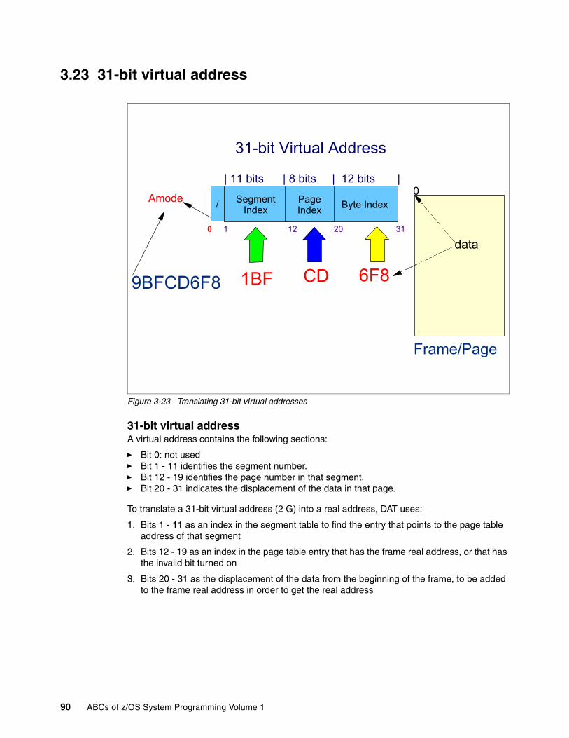
3.23 31-bit virtual address
Figure 3-23 Translating 31-bit vIrtual addresses
31-bit virtual addressA virtual address contains the following sections:
� Bit 0: not used � Bit 1 - 11 identifies the segment number.� Bit 12 - 19 identifies the page number in that segment. � Bit 20 - 31 indicates the displacement of the data in that page.
To translate a 31-bit virtual address (2 G) into a real address, DAT uses:
1. Bits 1 - 11 as an index in the segment table to find the entry that points to the page table address of that segment
2. Bits 12 - 19 as an index in the page table entry that has the frame real address, or that has the invalid bit turned on
3. Bits 20 - 31 as the displacement of the data from the beginning of the frame, to be added to the frame real address in order to get the real address
0 1 12 20 31
/ Segment Index Byte IndexPage
Index
31-bit Virtual Address
| 11 bits | 8 bits | 12 bits |
Amode
9BFCD6F8 1BF CD 6F8
data
Frame/Page
0
90 ABCs of z/OS System Programming Volume 1

3.24 64-bit virtual address translation
Figure 3-24 64-bit dynamic address translation
64-bit virtual address translationIn a 16 Exa address space with 64-bit virtual storage addressing, there are three additional levels of translation tables, called region tables. They are known as the region third table (R3T), the region second table (R2T), and the region first table (R1T). The region tables are 16 KB in length, and there are 2048 entries per table. Each region has 2 bytes.
Note the following points:
� When the first getmain is obtained above the bar, RSM creates the R3T. The R3T table has 2048 segment table pointers, and it provides addressability to the low 4 T addresses.
� When virtual storage addresses greater than 4 T are getmained, an R2T is created. An R2T has 2048 R3T table pointers, and it provides addressability to 8 P addresses.
� When virtual storage greater than 8 P is getmained, an R1T is created. The R1T has 2048 R2T table pointers, and it provides addressability to 16 EB.
Figure 3-24 illustrates the table hierarchy and sizes.
Segment and page table formats remain the same as for virtual addresses below the bar. When translating a 64-bit virtual address, and after you have identified the corresponding 2 G region entry that points to segment table, the process is the same as described previously.
RSM only creates the additional levels of region tables when it is necessary to back virtual storage that is mapped. The region tables are not built until a translation exception occurs.
R1TR2T
R2T
R3T
R3T
SGT
SGT
PGT
PGT
PAGE
PAGE
4 KBKilobytes 212
2 GBGigabytes
8 PPetabytes253 231 1 MB
Megabytes4TTerabytes
16EExabytes
2 64242 220
Chapter 3. z/OS storage concepts 91

For example, if an application requests 60 P of virtual storage, then the necessary R2T, R3T, segment table, and page tables are only created if they are needed to back a referenced page.
Up to five lookup tables may be needed by DAT to do translation, but the translation only starts from the table that provides translation for the highest usable virtual address in the address space.
92 ABCs of z/OS System Programming Volume 1

3.25 Translating a 64-bit virtual address
Figure 3-25 Translating a virtual address
Translating a 64-bit virtual addressTo translate a 64-bit virtual address into a real address, DAT uses:
� Bits 0 - 10 are the first region index into the R1T table.
� Bits 11 - 21 are the second region index into the R2T table.
� Bits 22 - 32 are the third region index into the R3T table.
� Bits 33 - 43 are the segment index into the segment table.
� Bits 44 - 51 are the page index into the page table
� Bits 52 - 63 indicate the data displacement into the page itself.
With 64-bit virtual addressing, there are now three more 11-bit region indexes to the three region tables, as illustrated in Figure 3-25.
RSM only creates the additional levels of region tables when it is necessary to back storage that is mapped.
0 11 22 33 44 52 63
| 11 bits | 11 bits | 11 bits | 11 bits | 8 bits | 12 bits |
R1 Index R2 Index R3 Index Segment Index
Page Index Byte Index
Same as 31-bit virtual address translation000000019BFCD6F8
1BF CD 6F83
Chapter 3. z/OS storage concepts 93
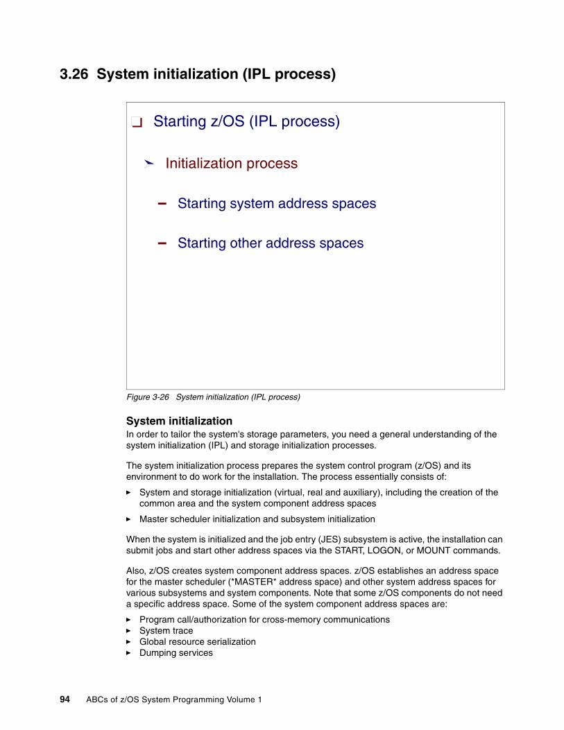
3.26 System initialization (IPL process)
Figure 3-26 System initialization (IPL process)
System initializationIn order to tailor the system's storage parameters, you need a general understanding of the system initialization (IPL) and storage initialization processes.
The system initialization process prepares the system control program (z/OS) and its environment to do work for the installation. The process essentially consists of:
� System and storage initialization (virtual, real and auxiliary), including the creation of the common area and the system component address spaces
� Master scheduler initialization and subsystem initialization
When the system is initialized and the job entry (JES) subsystem is active, the installation can submit jobs and start other address spaces via the START, LOGON, or MOUNT commands.
Also, z/OS creates system component address spaces. z/OS establishes an address space for the master scheduler (*MASTER* address space) and other system address spaces for various subsystems and system components. Note that some z/OS components do not need a specific address space. Some of the system component address spaces are:
� Program call/authorization for cross-memory communications� System trace� Global resource serialization� Dumping services
Starting z/OS (IPL process)
Initialization process
Starting system address spaces
Starting other address spaces
94 ABCs of z/OS System Programming Volume 1
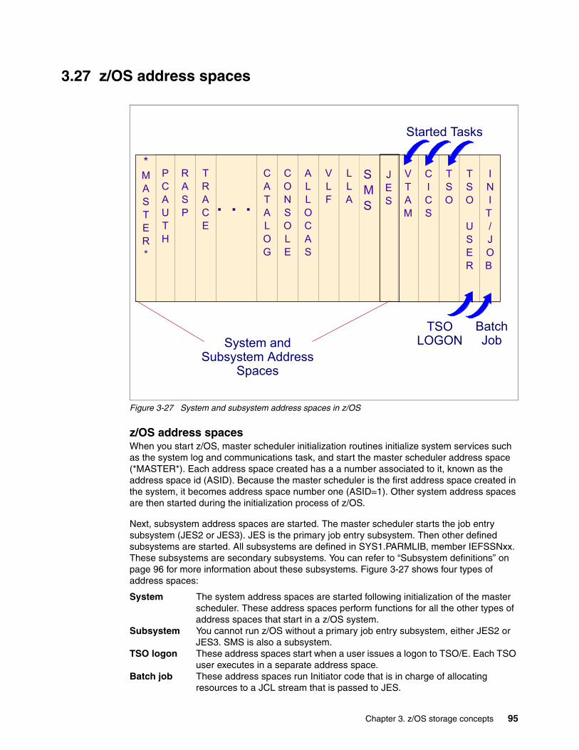
3.27 z/OS address spaces
Figure 3-27 System and subsystem address spaces in z/OS
z/OS address spacesWhen you start z/OS, master scheduler initialization routines initialize system services such as the system log and communications task, and start the master scheduler address space (*MASTER*). Each address space created has a a number associated to it, known as the address space id (ASID). Because the master scheduler is the first address space created in the system, it becomes address space number one (ASID=1). Other system address spaces are then started during the initialization process of z/OS.
Next, subsystem address spaces are started. The master scheduler starts the job entry subsystem (JES2 or JES3). JES is the primary job entry subsystem. Then other defined subsystems are started. All subsystems are defined in SYS1.PARMLIB, member IEFSSNxx. These subsystems are secondary subsystems. You can refer to “Subsystem definitions” on page 96 for more information about these subsystems. Figure 3-27 shows four types of address spaces:
System The system address spaces are started following initialization of the master scheduler. These address spaces perform functions for all the other types of address spaces that start in a z/OS system.
Subsystem You cannot run z/OS without a primary job entry subsystem, either JES2 or JES3. SMS is also a subsystem.
TSO logon These address spaces start when a user issues a logon to TSO/E. Each TSO user executes in a separate address space.
Batch job These address spaces run Initiator code that is in charge of allocating resources to a JCL stream that is passed to JES.
Started Tasks
*MASTER*
PCAUTH
RASP
TRACE
. . .
CATALOG
CONSOLE
ALLOCAS
VLF
LLA
JES
VTAM
CICS
TSO
TSO
USER
INI
T /JOB
Batch Job
TSO LOGONSystem and
Subsystem Address Spaces
SMS
Chapter 3. z/OS storage concepts 95

3.28 Subsystem definitions
Figure 3-28 Subsystem definitions in SYS1.PARMLIB
Subsystem definitionsA subsystem is a service provider that performs one function or many functions, but does nothing until it is requested. Although the term “subsystem” is used in other ways, in this book a subsystem must be the master subsystem or be defined to MVS using the EFSSNxx parmlib member. You can use either the keyword format or positional format of the IEFSSNxx parmlib member. IBM recommends that you use the keyword format, which allows you to define and dynamically manage your subsystems.
Subsystem initialization is the process of readying a subsystem for use in the system. The IEFSSNxx members of SYS1.PARMLIB contain the definitions for the primary subsystems (such as JES2 or JES3) and the secondary subsystems (such as SMS, CICS, DB2, and so on). For detailed information about the data contained in IEFSSNxx members for secondary systems, refer to the installation manual for the specific subsystem.
IEFSSNxx allows you to specify the following:
� The subsystem initialization routine to be given control during master scheduler initialization
� The input parameter string to be passed to the subsystem initialization routine
� A primary subsystem name and whether you want it started automatically
SUBSYS SUBNAME(subname) [CONSNAME(consname)] [INITRTN(initrtn) [INITPARM(initparm)]] [PRIMARY({NO|YES}) [START({YES|NO})]]
SUBSYS SUBNAME(JES2) PRIMARY(YES)SUBSYS SUBNAME(SMS) INITRTN(IGDSSIIN) INITPARM('ID=60,PROMPT=YES')
SYS1.PARMLIB: IEFSSNxx
SYS1.PARMLIB: IEASYSxx SSN=xx
96 ABCs of z/OS System Programming Volume 1

The order in which the subsystems are initialized depends on the order in which they are defined in the IEFSSNxx parmlib member on the SSN parameter. Unless you are starting the storage management subsystem (SMS), start the primary subsystem (JES) first.
Some subsystems require the services of the primary subsystem in their initialization routines. Problems can occur if subsystems that use the subsystem affinity service in their initialization routines are initialized before the primary subsystem. If you are starting SMS, specify its record before you specify the primary subsystem record.
The SSN parameter in IEASYSxx identifies the IEFSSNxx member that the system is to use to initialize the subsystems, as follows:
SSN= {aa } {(aa,bb,...) }
The two-character identifier, represented by aa (or bb, and so on), is appended to IEFSSN to identify IEFSSNxx members of Parmlib. If the SSN parameter is not specified, the system uses the IEFSSN00 Parmlib member.
The order in which the subsystems are defined on the SSN parameter is the order in which they are initialized. For example, a specification of SSN=(13,Z5) would cause those subsystems defined in the IEFSSN13 Parmlib member to be initialized first, followed by those subsystems defined in the IEFSSNZ5 Parmlib member.
Note: The storage management subsystem (SMS) is the only subsystem that can be defined before the primary subsystem.
Note: In general, it is good practice to make the subsystem name the same as the name of the member of SYS1.PROCLIB used to start the subsystem. If the name does not match, you may receive error messages when you start the subsystem.
Note: If you specify duplicate subsystem names in IEFSSNxx parmlib members, the system issues message IEFJ003I to the SYSLOG, the master console, and consoles that monitor routing code 10 messages.
Chapter 3. z/OS storage concepts 97

3.29 Multiprogramming and multiprocessing
Figure 3-29 Multiprogramming and multiprocessing
Concept of a task in z/OS To illustrate the concept of a task, imagine that you go to the movies: that is a task. And in order to complete that task, you drive a car along a street. Expanding the concept to z/OS, imagine that a credit card transaction arrives in z/OS through an end-user request. In this case, the processing of the transaction is the task. To complete that task, z/OS makes the processor execute several programs. In this analogy, processing the transaction is like going to the movies, programs are like streets, and processors are like cars.
Only one processor at a time can execute the same task. However, several processors executing different tasks can execute the same program (just as people driving different cars going to different places can share the same street).
MultiprogrammingMultiprogramming means that many tasks can be in a system at the same time, with each task running programs in its own address space (or sometimes in the same address space). In a single processor system (like a city with only one car), only one of these tasks can be active at a time.
However, the active task can lose control of the processor at any time (for example, because of I/O requests that place the task in a wait state, meaning it is not a candidate to get the processor). The operating system then selects which task should get control next, based in a number called dispatching priority.
ADDRESS SPACE
ADDRESS SPACE
ADDRESS SPACE
TASKTASK TASKSTASKS
TASKSTASKS
Processors
TASKTASKTASKSTASKS
98 ABCs of z/OS System Programming Volume 1

MultiprocessingMultiprocessing is a logical expansion of multiprogramming. Multiprocessing refers to the execution of more than one task simultaneously on more than one processor (which is like a city with several cars). All processors operate under a single copy of the operating system and share the same memory.
Keep the following points in mind:
� Each processor has a current Program Status Word (PSW), its own set of registers, and assigned storage locations.
� When a single processor shares central storage with other processors, then all of them are controlled by a single operating system copy. This is called a tightly coupled multiprocessing complex.
� When a single processor shares a common workload with others, but does not share central storage, this is called a loosely coupled multiprocessing complex.
Chapter 3. z/OS storage concepts 99

3.30 Program compile, link-edit, and execution
Figure 3-30 Executing a program after compiling and link-editing
Program compile, link-edit, and executionA z/OS system may appear to be one big block of code that drives your processor. Actually, z/OS is a complex system comprised of many different smaller blocks of code. Each of those smaller blocks of code perform a specific (specialized) function within the system.
Each module of symbolic language code is first assembled or compiled by one of the language translators or the assembler. The input to a language translator is a source module. The output from a language translator is an object module, made of control sections (CSECTs).
The Binder is a z/OS processing program that accepts object modules, control statements, and options as input. It combines these object modules, according to the requirements defined by the control statements and options, into a single output load module (executable code) that can be stored in a partitioned data set (PDS or PDSE) program library and loaded into storage for execution by the z/OS component program management loader. A load module can also be an input to the Binder.
Each system function is composed of one or more load modules.This is also true for an installation application. In a z/OS environment, a load module represents the basic unit of machine-readable executable code. Load modules are created by combining one or more object modules and processing them with a link-edit utility. The link-editing of modules is a process that resolves external references and addresses. The functions on your system, therefore, are one or more object modules that have been combined and link-edited.
After Link-edit
PROGRAMLIBRARY
PROGRAM B
PROGRAM A
0
140 KB
80 KB
After compilation
PROGRAM A (CSECT)
080 KB
PROGRAM B (CSECT)
60 KB 0
16 MB
2 GB
0
20 KB
Common
MYPROG
2-GB VirtualStorageAddress Space
MYPROGObject Modules
Load Module
100 ABCs of z/OS System Programming Volume 1

3.31 Library Lookaside (LLA)
Figure 3-31 Library Lookaside
Library Lookaside (LLA)LLA is a z/OS function that improves system performance by reducing the amount of I/O needed to locate and fetch load modules from DASD storage (PDS data sets). A PDS is stored only on a direct access storage device. It is divided into sequentially organized members, each described by one or more directory entries. Each member has a unique name, 1 to 8 characters long, stored in a directory that is part of the data set. The records of a given member are written or retrieved sequentially.
The main advantage of using a PDS is that, without searching the entire data set, you can retrieve any individual member after the data set is opened. For example, in a program library that is always a PDS, each member is a separate program or subroutine. The individual members can be added or deleted as required. When a member is deleted, the member name is removed from the directory, but the space used by the member cannot be reused until the data set is reorganized; that is, compressed using the IEBCOPY utility.
LLA services run in an LLA address space, which is a started task. They improve module fetch performance in the following ways:
� LLA maintains, in an LLA address space, copies of the PDS directories. To fetch a module, the system first searches the directory for the load module location in the PDS data set. The system can quickly search the LLA copy of a directory in virtual storage instead of using costly I/O to search the directories on DASD.
� LLA places copies (staging) of selected load modules in a Virtual Lookaside Facility (VLF) data space (when the LLA class is defined to VLF). VLF is another z/OS component in
//STEP EXEC PGM=ABCLINK EP=XYZLOAD EP=MYAPLXCTL EP=PGM00ATTACH EP=...
VLF data space
Appl
icat
ions
and
sys
tem
Ad
dres
s Sp
aces
Directory records
LLA Address Space
ABCmember
PGM00
XYZ member
MYAPL
Directories records
Application load library
System load library
Directory records
Statistics
Chapter 3. z/OS storage concepts 101

charge of keeping load modules and specific data in virtual storage, to avoid I/O operations; refer to “Virtual Lookaside Facility (VLF)” on page 103. for more information about this topic.
A data space is like an address space but it only contains data, not instructions. The system can quickly fetch modules from virtual storage, rather than using slower I/O to fetch the modules from DASD.
� LLA determines which modules, if staged, would provide the most benefit to module fetch performance. LLA evaluates modules as candidates for staging based on statistics LLA collects about the members of the PDS data sets it manages, such as module size, fetch count, and the time required to fetch a particular module.
The benefits of LLA apply only to load modules that are retrieved through the system functions LINK, LOAD, ATTACH, XCTL, and XCTL. Directory entries for the primary system library (SYS1.LINKLIB), load modules libraries concatenated to it as declared in LNKLSTxx member of SYS1.PARMLIB, and additional production libraries named in SYS1.PARMLIB(CSVLLAxx) are read into the private area of the LLA AS during its initialization. Subsequent searches for programs in these libraries begin with the directories in LLA, and not in the directories on DASD.
You obtain the most benefit from LLA when you have both LLA and VLF functioning together. This can be achieved by defining the LLA class to VLF and starting VLF, so the most active modules from LLA-managed libraries are staged into the DCSVLLA VLF data space.
102 ABCs of z/OS System Programming Volume 1
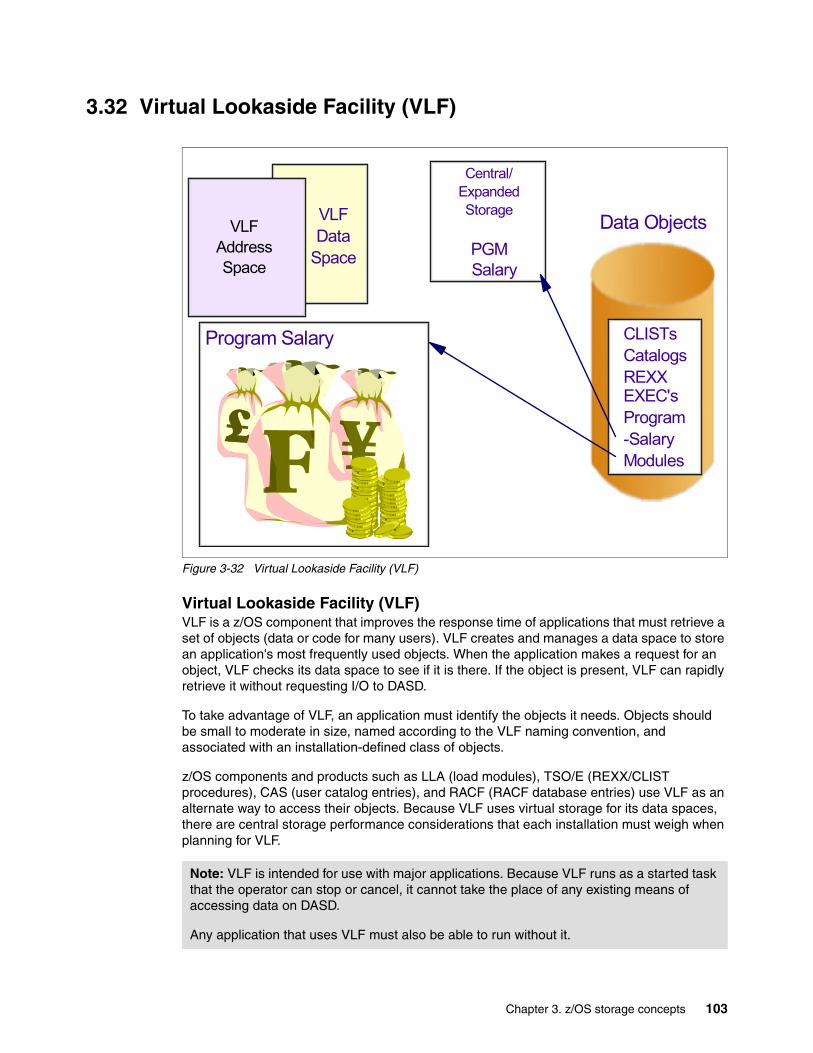
3.32 Virtual Lookaside Facility (VLF)
Figure 3-32 Virtual Lookaside Facility (VLF)
Virtual Lookaside Facility (VLF)VLF is a z/OS component that improves the response time of applications that must retrieve a set of objects (data or code for many users). VLF creates and manages a data space to store an application's most frequently used objects. When the application makes a request for an object, VLF checks its data space to see if it is there. If the object is present, VLF can rapidly retrieve it without requesting I/O to DASD.
To take advantage of VLF, an application must identify the objects it needs. Objects should be small to moderate in size, named according to the VLF naming convention, and associated with an installation-defined class of objects.
z/OS components and products such as LLA (load modules), TSO/E (REXX/CLIST procedures), CAS (user catalog entries), and RACF (RACF database entries) use VLF as an alternate way to access their objects. Because VLF uses virtual storage for its data spaces, there are central storage performance considerations that each installation must weigh when planning for VLF.
Note: VLF is intended for use with major applications. Because VLF runs as a started task that the operator can stop or cancel, it cannot take the place of any existing means of accessing data on DASD.
Any application that uses VLF must also be able to run without it.
Data Objects
CLISTsCatalogsREXX EXEC'sProgram-SalaryModules
VLFData
SpaceSalary
Central/ExpandedStorage
PGM
Program Salary
VLFAddressSpace
Chapter 3. z/OS storage concepts 103

3.33 Memory hierarchy
Figure 3-33 Memory hierarchy
Memory hierarchyThe memory hierarchy shown in Figure 3-33 illustrates the different layers of memory along a computational process. The higher the layer of memory, then the faster, more expensive, and smaller it is. The top layers are directly accessed by the processor.
The problem is how to distribute data and programs across memory, with regard to their importance to the business and their frequency of use. There are several considerations to keep in mind:
� Which data (and programs) need to migrate to a lower layer when the occupied layer is full or close to full? In this case there are two algorithms can be used:
– A least recently used (LRU) algorithm keeps the most referenced data or programs in storage. This assumes, for commercial processing that, if data or code was referenced in the past, it will likely be referenced in the future, as well. LRU is very good for random access, such as in an online environment.
– A sequential algorithm is used for sequential access. After data is accessed in a high layer (such as central storage), it can be demoted to the DASD cache because there are no chances for a revisit.
� What to do with data that was updated in a volatile layer? In this case, there are also two algorithms that can be used:
– Store-in, where the updated data is kept in the volatile layer (central storage, for example) without being copied to the non-volatile lower layer (the DASD cache, for
CPUL2 CACHE
CPUL2 CACHE
CENTRALSTORAGE
CF STORAGE
DASD CACHE
DASD
VTS
TAPE
SIZE
SPEE
DCO
ST
VO
LATI
LEPR
ESU
MAB
lYN
ON
-VO
LATI
LE
STORAGE PYRAMID
104 ABCs of z/OS System Programming Volume 1

example). This algorithm favors performance but demands a log to keep write integrity. Examples of store-in include the L2 cache and the DB2 buffer pool in virtual storage (central storage).
– Store-through, where the updated data is immediately (synchronously) copied to the volatile lower layer (generally demanding an I/O operation to the DASD cache). This algorithm favors write integrity, but does not help performance. Examples of store-through include the L1 cache and the VSAM buffer pool in virtual storage (central storage).
� How can integrity problems be solved when the lower layers are shared between different copies of z/OS systems? Such data sharing helps continuous availability (24/7), but a Coupling Facility is needed.
Chapter 3. z/OS storage concepts 105

106 ABCs of z/OS System Programming Volume 1

Chapter 4. TSO/E, ISPF, JCL, and SDSF
This chapter describes how to use the basic products that a system programmer needs to install and customize a z/OS operating system. The following topics are covered:
� Time Sharing Option/Extensions (TSO/E)
� Interactive System Productivity Facility and Program Development Facility (ISPF/PDF)
� Job Control Language (JCL)
� Spool Display and Search Facility (SDSF)
4
© Copyright IBM Corp. 2008. All rights reserved. 107

4.1 z/OS facilities for system programmers
Figure 4-1 z/OS facilities for system programmers
z/OS facilities for system programmersAs a system programmer, you should be familiar with the basic tools used in your daily job. These tools and their uses are as follows:
� TSO/E and ISPF are used to:– Install and customize z/OS and other products– Communicate interactively with the operating system– Define and maintain user definitions– Create data sets and JCL, and submit jobs– Communicate with other TSO/E users– Develop and maintain programs in languages such as assembler, COBOL, FORTRAN,
Pascal, C, C++, JAVA, PL/I, REXX, CLIST, and so on.– Manipulate data
� JCL enables you to submit jobs and allocate resources.� SDSF is used to:
– Monitor• JOBs waiting for execution• Output waiting to be printed• System resources used by JOBs• System resources available for utilization
– Control• System resources like printers• JOB priority and class• JOB output priority and class
Time Sharing Option/Extended - (TSO/E)
Interactive System Productivity Facility - (ISPF)
Job Control Language - (JCL)
Spool Display and Search Facility - (SDSF)
108 ABCs of z/OS System Programming Volume 1

4.2 TSO/E
Figure 4-2 TSO/E
TSO/ETSO/E is a base element of z/OS, as it was with OS/390 and the MVS systems. TSO/E allows users to interactively share computer time and resources. In general, TSO/E makes it easier for people with all levels of experience to interact with the MVS system.
TSO/E has undergone continuous enhancements during its life, and it has became the primary user interface to the OS/390 system and, now, to the z/OS system.
TSO/E provides programming services that you can use in system or application programs. These services consist of programs, macros, and CLISTs. TSO/E services support a wide range of functions that are useful in writing system programs as well as application programs that exploit the full-screen capabilities of TSO/E.
CLISTs, REXX execs, servers, and command processors are specific types of programs that you can write to run in the TSO/E environment.
TSO/E usersTSO/E offers advantages to a wide range of computer users, including system programmers, application programmers, information center administrators, information center users, TSO/E administrators, and others who access applications that run under TSO/E. This book describes the major tasks that each of these users can perform using TSO/E.
Chapter 4. TSO/E, ISPF, JCL, and SDSF 109

4.3 TSO/E highlights
Figure 4-3 Key features of z/OS TSO/E
TSO/E highlightsSome highlights of TSO/E are:
� The Session Manager
The TSO/E Session Manager is an interface to line mode TSO/E. It saves the commands that you enter and the responses that you receive and allows you to re-display or print them. You can correct or change a command that is displayed on the screen without having to retype the entire command. By allowing you to re-display, change, and reuse your input, the Session Manager makes TSO/E easier to use.
� Commands
TSO/E provides numerous commands for both end users and programmers that allow them to interact with TSO/E and the MVS system. The ALLOCATE, FREE, and EDIT commands are examples of commands that allow users to manage their data sets. The TEST and TESTAUTH commands let programmers test assembler language programs, including command processors, APPC/MVS transaction programs, and other programs written in assembler language. The CONSOLE command lets users with CONSOLE command authority perform MVS operator activities from a TSO/E session.
� Online help
Terminal users can obtain online help for most TSO/E commands. Information Center Facility users can obtain help for each panel and message. TSO/E Enhanced
Session Manager
Commands
Online help
Console
Support for z/OS UNIX
CLIST
REXX
Data and notice handling
Security
110 ABCs of z/OS System Programming Volume 1
Connectivity Facility users can also obtain online help for terminal messages. Installations can also provide online help information to users in different languages.
� Data and notice handling
TSO/E simplifies the way in which data and notices are sent and received. For example, the TRANSMIT and RECEIVE commands let users send data and messages to other users in a network. The broadcast data set or individual user logs contain messages that either the system or another user sends using the SEND command. In addition, a recovery routine prevents broken mail chains that could occur when message handling is interrupted. Notices are also handled more efficiently during logon processing. TSO/E keeps a copy of notices in storage, thereby reducing the I/O operations needed to inform users of waiting messages when they log on.
� Logon processing
TSO/E provides a full-screen logon panel that makes the logon process easier by:
– Saving user attributes from one session to the next
– Allowing program function keys to be used during logon
– Allowing users to enter commands during logon
– Explaining the error when incorrect information is specified
The LOGON and ACCOUNT command processors allow users to request private areas of up to 2 gigabytes for each terminal session. Your installation can also customize the logon panel and the logon help panel, and customize logon processing using different exits.
� Language enablement
TSO/E allow installations to provide TSO/E messages and the TRANSMIT full-screen panel to users in different languages. The TSO/E CONSOLE command also supports the display of translated system messages issued during a console session.
The logon authorized pre-prompt exit and the PROFILE command support the specification of languages to be used in displaying translated information. An installation can specify help data sets for different languages in the IKJTSOxx member of SYS1.PARMLIB. Support for logon panels and their help text in different languages is also available.
The TSO/E REXX external function, SYSVAR provides support for new arguments that REXX execs can use to obtain language information. Execs can use this information together with the new SETLANG function to set the language in which REXX messages are displayed.
� Security
TSO/E provides several enhancements to support the use of security labels. Installations can also control communication between users to protect the security classification of information. For example, installations can control and audit the use of the SEND command. LISTBC command processing enhancements let installations restrict users from viewing messages for which they do not have the proper security.
� CLIST language
The CLIST language is a high-level programming language that lets programmers issue lists of TSO/E commands and JCL statements in combination with logical, arithmetic, and string-handling functions provided by the language. The programs, called CLISTs, can simplify routine user tasks, invoke programs written in other languages, and perform complex programming functions by themselves.
Chapter 4. TSO/E, ISPF, JCL, and SDSF 111

� Restructured Extended Executor (REXX) language support
REXX is a high-level procedures language that enables inexperienced users as well as experienced programmers to write structured programs called REXX execs. REXX execs can be executed in any MVS address space (both TSO/E and non-TSO/E). TSO/E also allows users to write APPC/MVS transaction programs in the REXX language.
Installations can acquire IBM Compiler and Library for REXX/370 (licensed program number 5695-013) or a functionally equivalent compiler. A compiled REXX exec executes more efficiently because the exec does not need to be interpreted at run time.
� The TSO/E service facility
The TSO/E service facility lets TSO/E users execute authorized or unauthorized programs, TSO/E commands, or CLISTs from an unauthorized environment, while maintaining system integrity.
� TSO Command Package
The TSO Command Package provides functions that help to improve productivity. The
functions included are:
– Support for running terminal sessions as batch jobs
– Automatic saving of data
– Accounting facility
– Defaults for the user-attribute data set
� The Information Center Facility
The Information Center Facility eases users into the data processing environment by providing a series of conversational panels. These panels eliminate numerous command-driven interactions between the user and the system. Information Center Facility provides panels that enable an administrator to maintain the facility, enroll users, and add, modify, and delete products.
� The Enhanced Connectivity Facility
The Enhanced Connectivity Facility (ECF) allows you to customize the way in which host server programs and PC requester programs communicate. IBM products or customer-written programs can supply the services.
The user can access MVS host services from a PC using IBM System/370-to-IBM Personal Computer ECF. This allows a DOS/PC user to interact with MVS or VM/SP systems using PC commands.
� Support for z/OS UNIX
Installations can use the functions provided by the TSO/E ALLOCATE and FREE commands to manipulate z/OS UNIX files.
112 ABCs of z/OS System Programming Volume 1

4.4 TSO/E customization
Figure 4-4 TSO/E required customization
TSO/E customizationTSO/E allows users to interactively work with the MVS system. After the required customization, users are able to log on and issue commands from TSO/E.
Each user is defined to TSO/E by storing its user ID, logon procedure name, and the TSO/E resources which it has authority to use. This can be done in either of two ways:
� User Attribute Data Set (UADS), using the ACCOUNT command
� RACF database
When RACF is installed, it can be used to control access to the system and store information about each TSO/E user. The RACF database contains profiles for every entity (user, data set, or group) defined to RACF. For more information about RACF, see z/OS Security Server RACF System Programmer's Guide, SA22-7681.
Customization of the TSO/E environment generally refers to making a TSO/E facility available or changing default values that affect TSO/E. You can customize:
� VTAM: You can change VTAM session protocols, provide substitute characters for unavailable keyboard characters, and override the default values used to start VTAM.
� TCAM: You can override the default values used to start TCAM.
� Logon limits: You can limit and manage the maximum number of concurrent logons, the user’s region size, and user access to applications.
Define TSO/E to VTAM or TCAM
Define the users allowed to log on to TSO/E
Create TSO/E logon procedure for users
Chapter 4. TSO/E, ISPF, JCL, and SDSF 113

� The logon/logoff process: You can change how often the system displays the logon proceeding message, limit the number of attempts a user can make at entering information in response to logon prompts, tailor the reconnect option, and suppress messages that are generated during the execution of the logon job. You can also review factors that affect logon performance, such as using STEPLIBs in logon JCL, and you can write exits to further customize the logon/logoff process. Your installation can use security labels (SECLABEL) if the proper products are installed.
� ISPF/PDF and others products: You can make ISPF/PDF and others products that run in the TSO environment available to TSO/E users.
� Authorized commands and programs: You can select which authorized commands and programs users can use.
� Command/program invocation platform support: You can invoke TSO/E commands and programs on the command/program invocation platform. Both authorized and unauthorized commands and programs are supported.
� Command availability in the background: You can make specific commands unavailable for use in the background.
� TRANSMIT and RECEIVE availability: You can make the TRANSMIT and RECEIVE commands available.
� HELP data set usage: You can customize the use of HELP data set members.
� Host services availability: You can make host services available to personal computer (PC) users.
� Language support: You can provide information to users in their national language.
For more details about customization, refer to z/OS TSO/E Customization, SA22-7783.
Note: In z/OS.e, the number of concurrent TSO/E sessions is limited to eight.
114 ABCs of z/OS System Programming Volume 1

4.5 TSO/E: TCAS start procedure
Figure 4-5 TSO/E: TCAS start procedure
TSO/E: TCAS start procedureBefore a user can log on to TSO/E, both VTAM and the terminal control address space (TCAS) must be active in the system. The system operator enters the START command to start VTAM.
Once VTAM has been started, the system operator enters the START command to start TSO/E and activate TCAS. TCAS accepts logons from TSO/VTAM users and creates an address space for each user.
The TCAS (TSO) start procedure is usually stored at SYS1.PROCLIB. In the start procedure you specify the TSOKEYxx SYS1.PARMLIB member that contains the parameters to be used by TCAS to control the time-sharing buffers, maximum number of users, and other operational variables, as pointed by the PARMLIB DD card of the start procedure. If the PARMLIB DD card is not coded in the procedure, SYS1.PARMLIB is used.
When a user logs on, the VTAM terminal I/O coordinator (VTIOC) is initialized. VTIOC controls the movement of data between TSO/E and VTAM. The Parmlib member TSOKEY00 or an installation-defined alternate member contains parameters that are used during VTIOC initialization. If a member other than TSOKEY00 is used, the operator must include the member name either on the START command or in the procedure that the START command invokes. For a description of TSOKEY00, see z/OS MVS Initialization and Tuning Reference, SA22-7592.
//TSO PROC MBR=TSOKEY00 //* LIB: CPAC.PROCLIB(TSO) //* DOC: THIS IS THE CATALOGED PROCEDURE USED //* FOR STARTING TSO/VTAM TIME SHARING. THE //* TERMINAL CONTROL ADDRESS SPACE (TCAS) MUST //* BE ACTIVE WHEN RUNNING TSO/VTAM TIME SHARING. //* //* NOTE: THE PARMLIB DD STATEMENT IDENTIFIES THE PARMLIB //* DATA SET AND MEMBER THAT CONTAINS TSO/VTAM TIME //* SHARING PARAMETERS. THE MEMBER MAY EITHER BE //* SPECIFIED ON THE START COMMAND OR DEFAULTED TO //* TSOKEY00. //* //* THE PRINTOUT DD STATEMENT IDENTIFIES WHERE THE //* TIME SHARING PARAMETERS THAT ARE USED SHOULD BE //* LISTED. //* //* FREE=CLOSE IS CODED SO THAT THE DATA SETS ASSOCIATED//* WITH BOTH THE PARMLIB AND PRINTOUT DD STATEMENTS //* WILL BE DEALLOCATED WHEN THE DATA SETS ARE CLOSED. //* //STEP1 EXEC PGM=IKTCAS00,TIME=1440 //PARMLIB DD DSN=CPAC.PARMLIB(&MBR),DISP=SHR,FREE=CLOSE //PRINTOUT DD SYSOUT=*,FREE=CLOSE //*
Chapter 4. TSO/E, ISPF, JCL, and SDSF 115

4.6 TSO/E logon procedure
Figure 4-6 TSO/E logon procedure
TSO/E logon procedureA TSO/E logon procedure contains JCL statements that execute the required program and allocate the required data sets to enable a user to acquire the resources needed to use TSO/E. To log on to TSO/E, a user must have access to at least one logon procedure.
The logon procedure is usually located in data set SYS1.PROCLIB or another library identified in the PROCxx concatenation in the JES2 startup procedure, or in the IATPLBxx DD statement in the JES3 startup procedure. TSO/E provides a logon procedure in SYS1.PROCLIB called IKJACCNT for system programmers to access the system, for example, during the initial installation or if there are problems with the RACF database. Figure 4-6 shows a sample logon procedure. The statements specify:
PGM=IKJEFT01 Identifies the program to be executed. IKJEFT01 is the TSO/E-supplied Terminal Monitor Program (TMP) that provides an interface between the user command processors and the TSO/E control program. It obtains commands, gives control to command processors, and monitors their execution. This program can also be executed in the background by submitting JCL. Instead of the IKJEFT01 program, an installation can use the Session Manager program (ADFMDF03) or its own terminal monitor program.
PARM You can pass to IKJEFT01 a command, CLIST, REXX, or a program to be interpreted as the first line of input from the terminal after the user has logged on. In the example, it executes a CLIST or a REXX named BRDCST.
//*----------------------------------------------------//* SERVERPAC LOGON PROCEDURE //* //* THIS PROCEDURE ENABLES USERS TO LOG ON TO TSO/E. //* THE CLIST ISPPDF, WHICH RESIDES IN CPAC.CMDPROC, //* IS EXECUTED AT FIRST TO INVOKE THE ISPF. //*----------------------------------------------------//IKJACCNT PROC //IKJACCNT EXEC PGM=IKJEFT01,DYNAMNBR=500,PARM=ISPPDF //SYSPROC DD DISP=SHR,DSN=CPAC.CMDPROC //SYSHELP DD DISP=SHR,DSN=SYS1.HELP // DD DISP=SHR,DSN=SYS1.SASFPHLP // DD DISP=SHR,DSN=ISF.SISFHELP // DD DISP=SHR,DSN=REXX.V1R3M0.SEAGHENU // DD DISP=SHR,DSN=REXX.V1R3M0.SFANHENU // DD DISP=SHR,DSN=SYS1.SBDTHELP // DD DISP=SHR,DSN=SYS1.HELPENP // DD DISP=SHR,DSN=ISP.SISPHELP //SYSLBC DD DISP=SHR,DSN=SYS1.BRODCAST //SYSPRINT DD TERM=TS,SYSOUT=* //SYSTERM DD TERM=TS,SYSOUT=* //SYSIN DD TERM=TS //*
116 ABCs of z/OS System Programming Volume 1

DYNAMNBR Defines the number of data sets that can be dynamically allocated at the same time. A constant of 2 is always added to the DYNAMNBR value you specify. It allows data sets to be more quickly reallocated because control blocks for data sets remain in storage, even after the data sets have been de-allocated. You should choose the value for DYNAMNBR carefully. The value should be large enough that it is not readily exceeded by the number of dynamic allocation requests made during the user's session. However, the larger the value you specify for DYNAMNBR the more virtual storage is used. The actual amount of virtual storage depends on the number of data sets the user allocates and de-allocates in a session. The value cannot exceed the number of concurrently allocated resources specified in the SYS1.PARMLIB member ALLOCxx, parameter TIOT SIZE. For details, refer to z/OS MVS Initialization and Tuning Reference, SA22-7592.
SYSIN Specifies that SYSIN is the user's terminal.
SYSPRINT Specifies that SYSPRINT is to be directed to the user's terminal.
Additional data sets can be allocated dynamically during the user's session or can be defined in the logon procedure. The following DD statements have special meaning and can be included in the logon procedure:
SYSPROC Defines the current REXX exec or CLIST library to be searched when the user uses the implicit form of the EXEC command. Figure 4-6 shows the explicit form of the EXEC command and the library name is specified in the command. The implicit form would be BRDCST.
SYSEXEC Defines the current REXX exec library concatenation to the EXEC command when users use the implicit form of the command. By default, the system searches SYSEXEC first, followed by SYSPROC.
The data sets described in SYSPROC and SYSEXEC DD statements must be partitioned, and have a record format of V, VB, F, or FB. You can allocate them dynamically using the ALLOCATE command and activate them with the ALTLIB command.
Chapter 4. TSO/E, ISPF, JCL, and SDSF 117

4.7 TSO/E logon process in a VTAM environment
Figure 4-7 TSO/E logon process in a VTAM environment
TSO/E logon process in a VTAM environmentIn a VTAM environment, when a user enters a LOGON command to the TSO applid:
1. VTAM receives the command and passes it to the TCAS address space.
2. If the maximum number of users logged on in the system is reached, the logon is rejected; if not, and the user ID was not specified, TCAS prompts for the user ID.
3. Once the user ID is specified, TCAS verifies that the user has authority to use TSO/E. Depending on the installation customization, a full-screen logon panel is shown to the user. Figure 4-8 on page 119 shows the panel displayed when the user is RACF defined. The values shown in the fields PROCEDURE, ACCT NMBR, SIZE, and COMMAND are the same the user entered for the previous TSO/E session. If this is the first session, they are the default values. The command entered in the COMMAND field is executed after any command entered in the PARM field on the EXEC statement of the logon procedure.
4. After the Enter key is pressed, TSO/E verifies the values entered, then the user ID and the logon procedure name is passed to JES. The JCL is interpreted and converted. The MASTER creates the user address space and the resources specified in the JCL are allocated.
5. The user receives a screen with the READY prompt at the left top corner of the screen. This is called line-mode TSO/E. Now TSO/E is ready to accept commands, and user interfaces such as ISPF or SDSF can be called.
Logon TSO user00
VTAM AS
USER00AS
TCASAS
JESAS
MASTER AS
118 ABCs of z/OS System Programming Volume 1
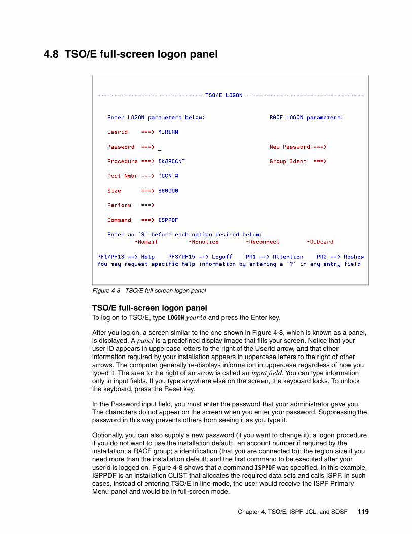
4.8 TSO/E full-screen logon panel
Figure 4-8 TSO/E full-screen logon panel
TSO/E full-screen logon panelTo log on to TSO/E, type LOGON yourid and press the Enter key.
After you log on, a screen similar to the one shown in Figure 4-8, which is known as a panel, is displayed. A panel is a predefined display image that fills your screen. Notice that your user ID appears in uppercase letters to the right of the Userid arrow, and that other information required by your installation appears in uppercase letters to the right of other arrows. The computer generally re-displays information in uppercase regardless of how you typed it. The area to the right of an arrow is called an input field. You can type information only in input fields. If you type anywhere else on the screen, the keyboard locks. To unlock the keyboard, press the Reset key.
In the Password input field, you must enter the password that your administrator gave you. The characters do not appear on the screen when you enter your password. Suppressing the password in this way prevents others from seeing it as you type it.
Optionally, you can also supply a new password (if you want to change it); a logon procedure if you do not want to use the installation default;, an account number if required by the installation; a RACF group; a identification (that you are connected to); the region size if you need more than the installation default; and the first command to be executed after your userid is logged on. Figure 4-8 shows that a command ISPPDF was specified. In this example, ISPPDF is an installation CLIST that allocates the required data sets and calls ISPF. In such cases, instead of entering TSO/E in line-mode, the user would receive the ISPF Primary Menu panel and would be in full-screen mode.
Chapter 4. TSO/E, ISPF, JCL, and SDSF 119
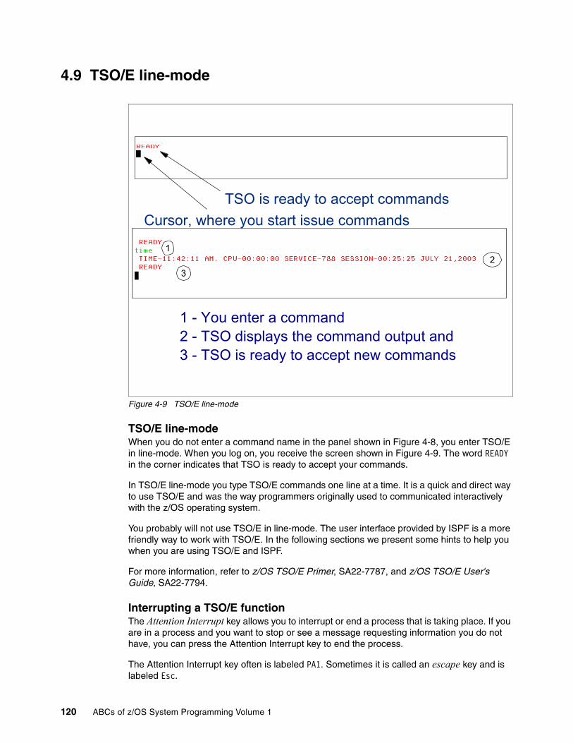
4.9 TSO/E line-mode
Figure 4-9 TSO/E line-mode
TSO/E line-modeWhen you do not enter a command name in the panel shown in Figure 4-8, you enter TSO/E in line-mode. When you log on, you receive the screen shown in Figure 4-9. The word READY in the corner indicates that TSO is ready to accept your commands.
In TSO/E line-mode you type TSO/E commands one line at a time. It is a quick and direct way to use TSO/E and was the way programmers originally used to communicated interactively with the z/OS operating system.
You probably will not use TSO/E in line-mode. The user interface provided by ISPF is a more friendly way to work with TSO/E. In the following sections we present some hints to help you when you are using TSO/E and ISPF.
For more information, refer to z/OS TSO/E Primer, SA22-7787, and z/OS TSO/E User's Guide, SA22-7794.
Interrupting a TSO/E functionThe Attention Interrupt key allows you to interrupt or end a process that is taking place. If you are in a process and you want to stop or see a message requesting information you do not have, you can press the Attention Interrupt key to end the process.
The Attention Interrupt key often is labeled PA1. Sometimes it is called an escape key and is labeled Esc.
Cursor, where you start issue commandsTSO is ready to accept commands
12
3
1 - You enter a command2 - TSO displays the command output and3 - TSO is ready to accept new commands
120 ABCs of z/OS System Programming Volume 1

4.10 Using TSO/E as batch job
Figure 4-10 TSO/E batch
Using TSO/E as batch jobInstead of waiting at a terminal for your job to run, you can use the terminal to prepare a job containing the commands and data you would have entered at the terminal, then use the SUBMIT command to run the job. In this case, you are using the facilities of TSO/E exactly as if you submitted the commands individually at the terminal. You need the following JCL statements to submit your job:
� A JOB statement to identify your job
� An EXEC statement with the name of the TSO/E terminal monitor program (IKJEFT01, IKJEFT1A, or IKJEFT1B)
� At least, the following ddnames:
a. SYSTSPRT, which is used to control the output for your job. You can specify this DD as SYSOUT.
b. SYSTSIN, which is used as input for your TSO/E commands. It can be in stream (use a /* to indicate the end of the stream).
� The DDNAMEs required by the application you intend to run.
DD name where you put the TSO commands
DD name for command output
//MIRIAM2 JOB 19,MIRIAM,NOTIFY=&SYSUID,MSGCLASS=T, // MSGLEVEL=(1,1),CLASS=A //*-----------------------------------------------------------* //* THIS IS A SAMPLE TSO BATCH JCL * //*-----------------------------------------------------------* //STEP1 EXEC PGM=IKJEFT01 //SYSPROC DD DSN=SYS1.OS390.CLIST,DISP=SHR //SYSTSIN DD * DELETE 'MY.DATASET' PROFILE /* //SYSTSPRT DD SYSOUT=*
Chapter 4. TSO/E, ISPF, JCL, and SDSF 121

4.11 TSO/E Profile command
Figure 4-11 TSO/E PROFILE command
TSO/E Profile commandUnder TSO/E you always have a TSO profile, which is kept from one session to another. The way you issue the command to see your TSO profile depends on which environment you are running in:
� In TSO/E line-mode environment, type PROFILE and press the Enter key.� In ISPF/PDF environment, type TSO PROFILE in the command line.
To change the TSO profile, type the PROFILE command followed by its operands and values. PROFILE can be shortened to PROF.
Figure 4-11 shows the command in line-mode. The command output is shown at 1. When you use PREFIX in your TSO profile, all data sets you refer to, when not imbedded in single quotes, are prefixed with your prefix, as shown at 2. To inactivate the prefix, enter the command PROFILE NOPREFIX, as shown at 3. Now, you do not have to use quotes, but you have to inform the complete data set name, as shown at 5; otherwise, you will receive an error message or delete a wrong data set.
You can issue PROFILE MSGID to have all diagnostic messages you receive identified by their IDs, as shown at 6.
You can add the LIST operand in your PROFILE command to list the new profile after the change, as shown at 6.
For more information about the PROFILE command and its operands, refer to z/OS TSO/E Command Reference, SA22-7782.
1
2
3
4
5
6
READY profile CHAR(0) LINE(0) PROMPT INTERCOM NOPAUSE NOMSGID MODE WTPMSG NORECOVER PREFIX(MIRIAM) PLANGUAGE(ENU) SLANGUAGE(ENU) DEFAULT LINE/CHARACTER DELETE CHARACTERS IN EFFECT FOR THIS TERMINAL READY delete old.dataset.sample1 ENTRY (A) MIRIAM.OLD.DATASET.SAMPLE1 DELETED READY profile noprefix READY profile CHAR(0) LINE(0) PROMPT INTERCOM NOPAUSE NOMSGID MODE WTPMSG NORECOVER NOPREFIX PLANGUAGE(ENU) SLANGUAGE(ENU) DEFAULT LINE/CHARACTER DELETE CHARACTERS IN EFFECT FOR THIS TERMINAL READY delete old.dataset.sample2 ENTRY (A) OLD.DATASET.SAMPLE2 DELETED READY prof msgid list IKJ56688I CHAR(0) LINE(0) PROMPT INTERCOM NOPAUSE MSGID MODE WTPMSG NORECOVER NOPREFIX PLANGUAGE(ENU) SLANGUAGE(ENU) IKJ56689I DEFAULT LINE/CHARACTER DELETE CHARACTERS IN EFFECT FOR THIS TERMINAL READY profile prefix(newpref) list IKJ56688I CHAR(0) LINE(0) PROMPT INTERCOM NOPAUSE MSGID MODE WTPMSG NORECOVER PREFIX(NEWPREF) PLANGUAGE(ENU) SLANGUAGE(ENU) IKJ56689I DEFAULT LINE/CHARACTER DELETE CHARACTERS IN EFFECT FOR THIS TERMINAL READY
122 ABCs of z/OS System Programming Volume 1
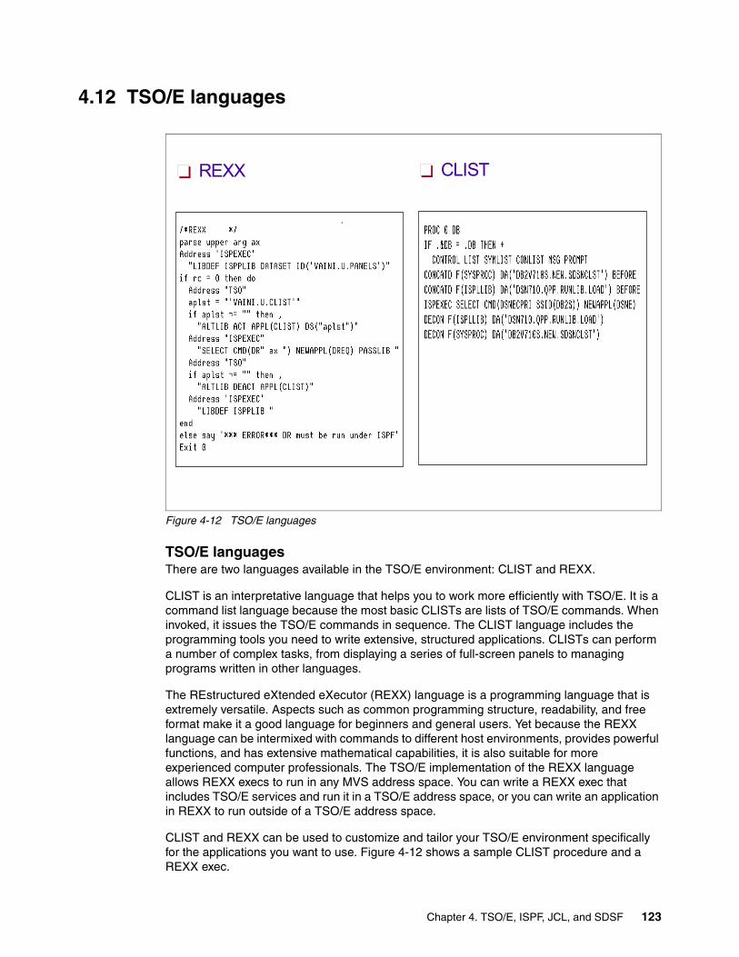
4.12 TSO/E languages
Figure 4-12 TSO/E languages
TSO/E languagesThere are two languages available in the TSO/E environment: CLIST and REXX.
CLIST is an interpretative language that helps you to work more efficiently with TSO/E. It is a command list language because the most basic CLISTs are lists of TSO/E commands. When invoked, it issues the TSO/E commands in sequence. The CLIST language includes the programming tools you need to write extensive, structured applications. CLISTs can perform a number of complex tasks, from displaying a series of full-screen panels to managing programs written in other languages.
The REstructured eXtended eXecutor (REXX) language is a programming language that is extremely versatile. Aspects such as common programming structure, readability, and free format make it a good language for beginners and general users. Yet because the REXX language can be intermixed with commands to different host environments, provides powerful functions, and has extensive mathematical capabilities, it is also suitable for more experienced computer professionals. The TSO/E implementation of the REXX language allows REXX execs to run in any MVS address space. You can write a REXX exec that includes TSO/E services and run it in a TSO/E address space, or you can write an application in REXX to run outside of a TSO/E address space.
CLIST and REXX can be used to customize and tailor your TSO/E environment specifically for the applications you want to use. Figure 4-12 shows a sample CLIST procedure and a REXX exec.
CLISTREXX
Chapter 4. TSO/E, ISPF, JCL, and SDSF 123

4.13 Interactive System Productivity Facility (ISPF)
Figure 4-13 Interactive System Productivity Facility (ISPF)
Interactive System Productivity Facility (ISPF)The Interactive System Productivity Facility/Program Development Facility (ISPF/PDF) is a set of panels that help you manage libraries of information on the MVS system. The libraries are made up of units called data sets that can be stored and retrieved. You can have different kinds of information in data sets. Some examples are:
� Source code � Data such as inventory records, personnel files, or a series of numbers to be processed � Load modules
ISPF can be used in many ways. Some examples are the following:
� Users can edit, browse and print data.
� Data processing administrators and system programmers can use ISPF to:
– Monitor and control program libraries
– Communicate with MVS through TSO commands, CLISTs, or REXX EXECs
� Programmers can use ISPF to develop a batch, interactive, or any other type of program and its documentation.
� Terminal users can invoke a wide range of utilities like search, compare, compilers, and so forth.
� Programmers can use ISPF services to develop dialogs.
Time Sharing Option/Extended - (TSO/E)
Interactive System Productivity Facility - (ISPF)
Job Control Language - (JCL)
Spool Display and Search Facility - (SDSF)
124 ABCs of z/OS System Programming Volume 1

4.14 ISPF: Data set types supported
Figure 4-14 ISPF and ISPF/PDF data set types supported
ISPF: Data set types supportedA data set is a collection of logically related data; it can be a source program, a library of macros, or a file of data records used by a processing program. Data records are the basic unit of information used by a processing program. ISPF supports the following data set types for any ISPF options, such as Edit, Browse, and Delete:
� Sequential� Partitioned (PDS) and Partitioned Extended (PDSE)
For VSAM data sets, ISPF supports creation, obtaining data set information, and deletion. Browse and Update is supported by DITTO, an IBM licensed program installed under ISPF.
ISPF does not support the following:
� Record format variable block spanned (VBS) data sets� Direct Access (DA) data sets� Tape data sets� Generation data group (GDG) base data sets
In a sequential data set, records are stored and retrieved in a sequential order.
A partitioned data set is like a collection of sequential data sets, called members, each one having a name. A directory index is used to locate members in the partitioned data set. The directory consists of 256-byte records, each one containing directory entries. There is one directory entry for each member.
Record 1 Record 2 Record 3 Record 4etc ...
Sequential Data Set
Entry for JCOPY Entry for COMPJCL Entry for SORT1
SORT1 JCOPY
JOB00 COMPJCL
SORT1 SORT1
Available space
Partitionated Data Set
Wasted space Recoverable by Compress Utility
Directory
POPOSequentialSequential
DASD
Chapter 4. TSO/E, ISPF, JCL, and SDSF 125

4.15 ISPF: Data set and member naming conventions
Figure 4-15 ISPF: Data set and member naming conventions
ISPF: Data set and member naming conventionsISPF allows you to create data sets and member names that follow the ISPF naming convention shown in Figure 4-15.
All data sets and member names created within ISPF are converted to uppercase. If you create members outside of ISPF that do not meet these conventions, they are displayed in ISPF member lists and can be selected from those lists. These member names can also be specified for the Browse service, with the exception of member names containing lowercase alphabetic characters. (ISPF converts the member name to uppercase before searching for the member and therefore cannot process a lowercase member.) Member names not meeting the ISPF naming convention are not supported for the other ISPF services. The same applies to data sets.
ISPF has very useful online help and tutorial facilities (available while using ISPF). For example, if you need help filling in the data requested by an ISPF utility, you can use the tutorial to help you understand the data entry requirements for that utility. For information about using the tutorial, see z/OS ISPF Dialog Developer's Guide, SC34-4821.
Data Set Name Convention:Unique name
Maximum 44 CharactersMaximum of 22 name segments: level qualifier
The first name in the left: High Level Qualifier (HLQ)The last name in the right: Low Level Qualifier (LLQ) Level qualifiers are separated by '.'
Each level qualifier:From 1 up to 8 charactersThe first must be alphabetical (A-Z) or national (@ # $)The 7 remaining: alphabetical, national, numeric (0-9) or hyphen (-)
Example: MYID.JCL.FILE2 HLQ: MYID 3 qualifiers Member Name of Partitionated Data Set:
8 BytesFirst byte: alphabetical (A-Z) or national (@ # $)The 7 remaining: alphabetical, national, numeric (0-9)
126 ABCs of z/OS System Programming Volume 1

4.16 ISPF components
Figure 4-16 ISPF components
ISPF componentsISPF consists of four major components as shown in Figure 4-16. These components are considered one element in all releases of z/OS.
ISPF Dialog Manager (DM)Dialog Manager provides services to dialogs and end-users. A dialog is the interaction between a person and a computer. It helps a person who is using an interactive display terminal to exchange information with a computer. The user starts an interactive application through an interface that the system provides. The dialog with the user begins with the computer displaying a panel and asking for user interaction. It ends when the task for which the interactions were initiated is completed. Dialog Manager is composed of six elements:
� Functions: A function is a command procedure or a program that performs processing requested by the user. It can invoke ISPF dialog services to display panels and messages, build and maintain tables, generate output data sets, and control operational modes. They can be written as:
– REXX or CLIST command procedures– Programs
� Panel definitions: A panel definition is a programmed description of the panel. It defines both the content and format of a panel. Most panels prompt the user for input. The user's response can identify which path is to be taken through the dialog, as on a selection panel. The response can be interpreted as data, as on a data-entry panel.
Dialog Manager
Functions
REXX or CLIST
Programs
Panels
Messages
Tables
Skeletons
Dialog variables
SCLM
Client/Server - The Workstation Agent Component
Chapter 4. TSO/E, ISPF, JCL, and SDSF 127

� Message definitions: Message definitions specify the format and text of messages to users. A message can confirm that a user-requested action is in progress or completed, or it can report an error in the user's input.
� Table: Tables are two-dimensional arrays that contain data and are created by dialog processing. They can be created as a temporary data repository, or they can be retained across sessions. A retained table can also be shared among several applications. The type and amount of data stored in a table depends on the nature of the application. Not all dialogs use tables.
� File tailoring skeletons: Skeletons work like a fill-in-the-blank exercise. They take dialog variables and put them into a data set containing statements that control the output format. The output data set can be used to drive other processes. File skeletons are frequently used to produce job data sets for batch execution. Some dialogs can use this kind of resource.
� Dialog variables: ISPF services use variables to communicate information among the various elements of a dialog application. ISPF provides a group of services for variable management. Variables can vary in length from zero to 32K bytes.
Program Development Facility (ISPF/PDF) Program Development Facility provides View, Browse, Edit, and library access services that can be combined in a dialog with any of the ISPF services. The library access services carry out functions involving members of a programming library. These functions include adding, finding, and deleting members, and displaying member lists.
Software Configuration Library Manager (SCLM)Software Configuration Library Manager (SCLM) is a software tool that helps you develop complex software applications. Throughout the development cycle, SCLM automatically controls, maintains, and tracks all of the software components of the application. You can lock the version being edited in a private library and then promote it. Use SCLM to create, control, maintain, and track software components for a project. For more information about SCLM, refer to z/OS ISPF Software Configuration Library Manager Reference, SC34-4818.
ISPF Client/Server - The Workstation Agent ComponentThe Workstation Agent Component enables you to run ISPF on a programmable workstation and display the panels using the display function of your workstation operating system. Manuals in the ISPF library refer to this as running in GUI mode. The ISPF WSA is supported on the following platforms:
� OS/2®� Microsoft® Windows� AIX®� HP-UX� Solaris™
Connecting to a workstation for data access has a direct impact on your installation’s CPU processing time. One reason for using the ISPF Client/Server function is to offload CPU cycles from the host to a less expensive workstation. But even if that is not your goal, an added benefit is that your users can use the connection for distributed editing. This means that they can use their favorite editor to work with your data, whether that means using a host editor on host and workstation files, or using a workstation editor on the same files. By making the connection to the workstation, a user can edit workstation files on ISPF, or host files on his workstation. The distributed edit function can be used in standard 3270 mode, or in ISPF GUI mode.
128 ABCs of z/OS System Programming Volume 1
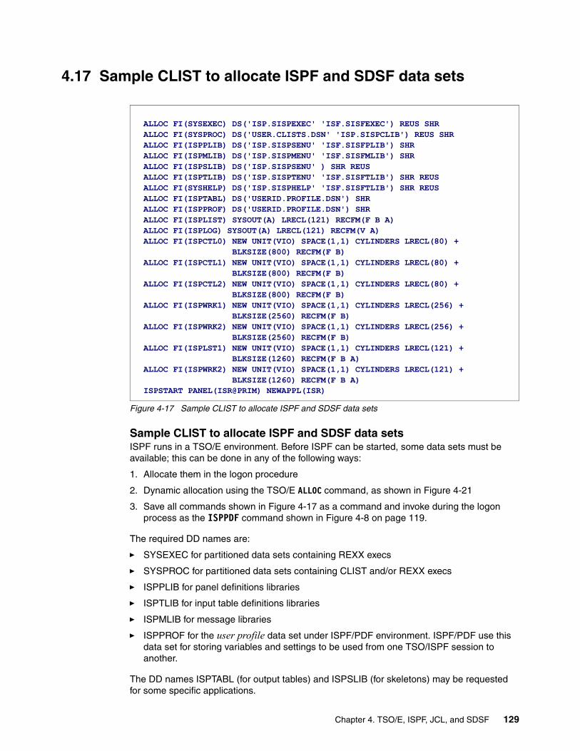
4.17 Sample CLIST to allocate ISPF and SDSF data sets
Figure 4-17 Sample CLIST to allocate ISPF and SDSF data sets
Sample CLIST to allocate ISPF and SDSF data setsISPF runs in a TSO/E environment. Before ISPF can be started, some data sets must be available; this can be done in any of the following ways:
1. Allocate them in the logon procedure
2. Dynamic allocation using the TSO/E ALLOC command, as shown in Figure 4-21
3. Save all commands shown in Figure 4-17 as a command and invoke during the logon process as the ISPPDF command shown in Figure 4-8 on page 119.
The required DD names are:
� SYSEXEC for partitioned data sets containing REXX execs
� SYSPROC for partitioned data sets containing CLIST and/or REXX execs
� ISPPLIB for panel definitions libraries
� ISPTLIB for input table definitions libraries
� ISPMLIB for message libraries
� ISPPROF for the user profile data set under ISPF/PDF environment. ISPF/PDF use this data set for storing variables and settings to be used from one TSO/ISPF session to another.
The DD names ISPTABL (for output tables) and ISPSLIB (for skeletons) may be requested for some specific applications.
ALLOC FI(SYSEXEC) DS('ISP.SISPEXEC' 'ISF.SISFEXEC') REUS SHR ALLOC FI(SYSPROC) DS('USER.CLISTS.DSN' 'ISP.SISPCLIB') REUS SHR ALLOC FI(ISPPLIB) DS('ISP.SISPSENU' 'ISF.SISFPLIB') SHR ALLOC FI(ISPMLIB) DS('ISP.SISPMENU' 'ISF.SISFMLIB') SHR ALLOC FI(ISPSLIB) DS('ISP.SISPSENU' ) SHR REUS ALLOC FI(ISPTLIB) DS('ISP.SISPTENU' 'ISF.SISFTLIB') SHR REUS ALLOC FI(SYSHELP) DS('ISP.SISPHELP' 'ISF.SISFTLIB') SHR REUS ALLOC FI(ISPTABL) DS('USERID.PROFILE.DSN') SHR ALLOC FI(ISPPROF) DS('USERID.PROFILE.DSN') SHR ALLOC FI(ISPLIST) SYSOUT(A) LRECL(121) RECFM(F B A) ALLOC FI(ISPLOG) SYSOUT(A) LRECL(121) RECFM(V A) ALLOC FI(ISPCTL0) NEW UNIT(VIO) SPACE(1,1) CYLINDERS LRECL(80) + BLKSIZE(800) RECFM(F B) ALLOC FI(ISPCTL1) NEW UNIT(VIO) SPACE(1,1) CYLINDERS LRECL(80) + BLKSIZE(800) RECFM(F B) ALLOC FI(ISPCTL2) NEW UNIT(VIO) SPACE(1,1) CYLINDERS LRECL(80) + BLKSIZE(800) RECFM(F B) ALLOC FI(ISPWRK1) NEW UNIT(VIO) SPACE(1,1) CYLINDERS LRECL(256) + BLKSIZE(2560) RECFM(F B) ALLOC FI(ISPWRK2) NEW UNIT(VIO) SPACE(1,1) CYLINDERS LRECL(256) + BLKSIZE(2560) RECFM(F B) ALLOC FI(ISPLST1) NEW UNIT(VIO) SPACE(1,1) CYLINDERS LRECL(121) + BLKSIZE(1260) RECFM(F B A) ALLOC FI(ISPWRK2) NEW UNIT(VIO) SPACE(1,1) CYLINDERS LRECL(121) + BLKSIZE(1260) RECFM(F B A) ISPSTART PANEL(ISR@PRIM) NEWAPPL(ISR)
Chapter 4. TSO/E, ISPF, JCL, and SDSF 129

For some data sets, if not pre-allocated, ISPF allocates them:
� ISPLOG DD name: The data set where ISPF logs commands issued by the user and some ISPF functions log errors detected.
� ISPLIST DD name: ISPF uses this data set when user requests printed output.
The DD names ISPCTLx (where x can be 1–9, A–W) are used by ISPF as a temporary data set. ISPF can use one for each logical screen to generate JCL or utility control statements or to generate listings. ISPF can run up to 32 logical screens at one time. The default value is 8. The installation can change the default value by modifying the ISRCONFG table. ISPCTL0 is used only by Edit for the SUBMIT command.
The DD names ISPWRKx are used by ISPF for file tailoring services with ISPFILE allocated to a PDS. The DD names ISPLSTx are used for generated listings. The same pre-allocation can be done by the ALLOCATE command in a CLIST or in a REXX exec to be executed before the ISPF start.
130 ABCs of z/OS System Programming Volume 1

4.18 ISPF primary option menu
Figure 4-18 ISPF primary option menu
ISPF primary option menuISPF is started in a TSO/E environment through an ISPF, or PDF, or ISPSTART command. The ISPF Primary Option Menu contains the options that you can use to create your own applications online. If your installation has a customized ISPF Primary Option Menu, the menu might not contain all of options shown in Figure 4-18, or it might contain certain installation-specific options.
Most ISPF panels have action bars at the top; many panels also have point-and-shoot text fields.
Chapter 4. TSO/E, ISPF, JCL, and SDSF 131

4.19 ISPF panel areas
Figure 4-19 ISPF panel areas
ISPF panel areasISPF panels can contain the following areas:
1. Action bar: The area at the top of an ISPF panel that contains choices that give you access to actions available on that panel.
2. Option: The fields in this column are point-and-shoot text fields. For example, if you want to select the Edit Panel, to create or change source data, you type it in the option input field and press Enter. You can also type commands in the Option field.
3. Dynamic status area: You can specify what you want to be displayed in this area; in Figure 4-19 it is descriptions of all the possible options you can take from this panel.
4. Function Keys: ISPF uses Common Use Access (CUA)-compliant definitions for function keys F1-F12. For example: PF1 is used to invoke the ISPF Help Function. You can eliminate this area by typing PFSHOW OFF in area 2, the Option field.
3
1
2
4
132 ABCs of z/OS System Programming Volume 1

4.20 Action bars
Figure 4-20 Action bars
Action barsAction bars give you another way to move through ISPF. If the cursor is located somewhere on the panel, there are several ways to move it to the action bar:
� Use the cursor movement keys to manually place the cursor on an action bar choice.
� Type ACTIONS on the command line and press Enter to move the cursor to the first action bar choice.
� Press F10 (Actions) or the Home key to move the cursor to the first action bar choice.
When you make an action bar selection, the selected item is highlighted and ISPF displays a pull-down menu, that is, a list of numbered choices extending from the selection you made on the action bar. Figure 4-20 shows the result when you select Utilities on your screen.
You can select an action either by typing in its number and pressing Enter or by selecting the action with your cursor. ISPF displays the requested panel. If your choice contains an ellipsis (...), ISPF displays a pop-up window. When you exit this panel or pop-up, ISPF closes the pull-down menu and returns you to the panel from which you made the initial action bar selection.
Note: ISPF does not provide a mouse emulator program. You can use Select in conjunction with point-and-shoot text fields and action bar choices to simulate moving the cursor to a field and pressing Enter.
Chapter 4. TSO/E, ISPF, JCL, and SDSF 133

4.21 Customizing your TSO/ISPF/PDF session
Figure 4-21 Customizing your TSO/ISPF/PDF session
Customizing your TSO/ISPF/PDF sessionYou can customize your TSO/ISPF/PDF session by selecting Options → General Settings as shown in Figure 4-21, Screen 1. In the resulting screen, Screen 2, the first line shows others action fields where you can choose to change default settings, like colors, function keys, and so forth.
ISPF Help functionISPF has a powerful Help function which can teach you how to use all the default ISPF options. Access it by pressing the Help program function key or typing help in the Command line. You can see and change the program function key assignments by using the KEYS command.
You can learn how to use ISPF by just using the help function. At the Primary Option Menu press Help to learn about the options. In the Help panel, press Help again to learn how to move through help panels. Some Help options are cursor-sensitive, meaning you have to move the cursor to that option to get more information.
A good source of information for beginners in the ISPF environment is Interactive System Productivity Facility Getting Started, SC34-4440.
2
Screen 1
Screen 2
134 ABCs of z/OS System Programming Volume 1

4.22 Allocating data sets: Utility option
Figure 4-22 Allocating a data set: Utilities option
Allocating data sets: Utility optionA data set, or file, is an area that is reserved on either disk or tape to enable you to write programs and store data. Before you can edit or store data, you must instruct the system to allocate some space on disk, often referred to as Direct Access Storage Devices (DASD), and provide information to identify the format of this data set.
There are two ways to allocate a data set:
1. Using ISPF dialogs
2. Using JCL
The first way is as follows:
In the primary menu, type 3 in the Option input field, and press the Enter key. Option 3 displays the utilities panel, as shown in Figure 4-23 on page 136.
Use ISPF Option 3
Chapter 4. TSO/E, ISPF, JCL, and SDSF 135

4.23 Utility Selection Panel
Figure 4-23 Utility Selection Panel option 2
Utility Selection PanelThe Utility Selection Panel gives you the ability to select utilities to perform a variety of functions, such as:
� Compress or print a data set
� Create, rename, delete a data set
� Move or copy data sets or members
� Search for strings in a data set
� Compare data sets
ISPF Option 3.2 enables you to reserve some space on a storage device and identify this space with a data set name, often referred to as a DSN or DSNAME.
In this example you will allocate a data set; to do this, type 2 in the Option field and press Enter.
Utility Selection Panel option 2
136 ABCs of z/OS System Programming Volume 1

4.24 Data Set Utility: Allocating a data set
Figure 4-24 Allocating a data set - Data Set Utility panel
Data Set Utility: Allocating a data setThe Data Set Utility panel presents a variety of actions you can perform. You can allocate, delete, rename, catalog, uncatalog, or obtain information about a specific data set. The V option allows you create and obtain information about VSAM data sets in a very easy way.
From the ISPF Primary Option Menu you can go directly to this panel by typing =3.2 in the Option field.
To allocate a data set, type A on the Option field. Next you specify the name of data set you want to create:
� A data set with a three-level name can be entered in the Project, Group, and Type fields as shown in area 1 in Figure 4-24. Type one level of the name in each field. ISPF does not add your prefix as HLQ.
� You can specify the data set name and optionally a volume, as shown in area 2 in of the panel:
Other Partitioned, Sequential or VSAM Data Set:Data Set Name. . . 'HLQ.XXX.XXXX.XXX'
If both a library (1) and a data set name (2) are specified on the same panel, the data set name takes priority. Therefore, to specify a library, leave the Data Set Name field blank. We
Note: Imbed the data set name in single quotes unless you want the HLQ to equal your prefix.
1
2
Chapter 4. TSO/E, ISPF, JCL, and SDSF 137
did not enter the data set name option field; therefore the values specified in the library name are used. See Figure 4-15 on page 126 for data set naming conventions.
Data set name standards are site-dependant, and may be protected by RACF or another security product. If you do not have the authority to allocate a DSN with a specific name, your request fails and you receive an error message.
Examples of some data set names:
� SYS1.PARMLIB
� SYS1.PARMLIB.BACKUP.D99156
� MIRIAM.PRIVATE.JCLLIB
� MIRIAM.TEST.NEW.SYSTEM.JCLLIB
The High Level Qualifier (HLQ) is the first part of the DSN. In the examples, the HLQs are SYS1 (usually reserved for MVS system DSNs), and MIRIAM, which could be your user ID. Some system data sets must be named as specified, but personal or in-house data sets should be named to be meaningful and easy to associate with a user or application, and to enable efficient security and DASD maintenance strategies to be maintained.
138 ABCs of z/OS System Programming Volume 1

4.25 Allocate New Data Set panel
Figure 4-25 Allocate New Data Set panel
Allocate New Data Set panelAfter pressing the Enter key, the Allocate New Data Set panel is displayed. This panel shows the information you have to provide in order to allocate the new data set.
In this example we are allocating a partitioned data set (PDS); this type of data set allows individual members within the data set. Most environments now utilize DFSMS to control data set allocation; therefore, it is not necessary to specify management class, storage class, or data class information. In most cases the defaults are satisfactory. We must, however, specify the following:
Space units The allocation units for our data set. The allocation units can be in blocks (BLKS), tracks (TRKS), cylinders (CYLS), KB, MB, bytes, or records.
Primary quantity The amount of primary space units we want to allocate.
Secondary quantity The space that can be allocated for secondary extents, if the primary quantity fills up. Non-extended data sets can have a maximum of 16 extents, which includes up to five multiple extents that may have been used to satisfy the primary extents.
Note: The exception to the 16 extent limitation is partitioned data set extended (PDSE) data sets, which can have up to 123 extents.
Chapter 4. TSO/E, ISPF, JCL, and SDSF 139

Directory blocks Must be specified for partitioned data sets. A directory is an index used to locate members in the partitioned data set. Each directory record consists of 256 bytes containing directory entries. There is one directory entry for each member. The directory is written at the beginning of the primary space. It must fit in the first extent of the data set. For partitioned data sets, be sure to request enough directory space to allow for growth of the data set. You cannot lengthen the directory once the data set is created. If the directory runs out of space, you must recreate the data set.
Record format Can be any valid combination of the following:
F Fixed length records
V Variable length records
U Undefined format records
B Blocked records
A ASA printer control characters
M Machine code printer control characters
S Standard (for F) or spanned (for V) - sequential data sets only
T Track-overflow feature
The option we used for a partitioned data set was FB.
Record length The logical record length, in bytes, of the records to be stored in the data set. In the case of a JCL or program library this value is 80 bytes.
Block size The block size (physical record length), in bytes, of the blocks to be stored in the data set. If records are specified, the block size specifies the average record length.
After pressing the PF3 (Exit) key, the successful response to the allocation is indicated on the Data Set Utility panel that reappears. You are returned to this after processing the Allocate New Data Set panel. The top right of the panel indicates Data set allocated.
We have now created a partitioned data set with the name, MIRIAM.PRIVATE.JCLLIB. This is an empty data set, so the first thing we do is add a member to this data set.
Note: The number of member entries that fit in a directory block is as follows:
– For a data set with ISPF statistics: six entries per block– For a data set without ISPF statistics: 21 entries per block– For a load module data set: four to seven entries, depending
upon attributes
140 ABCs of z/OS System Programming Volume 1

4.26 Edit function: Option 2
Figure 4-26 Edit: Option 2
Edit function: Option 2You can add a new member to a PDS using ISPF Option 2 (Edit) in the ISPF Primary Option Menu. When you choose this option, the Entry Edit panel is displayed.
You can also use option 2 to change an existing member. This can be accomplished by entering the name of the data set and member you want to change in the Edit Entry Panel.
Chapter 4. TSO/E, ISPF, JCL, and SDSF 141

4.27 Edit Entry Panel
Figure 4-27 Edit Entry Panel
Edit Entry PanelIn this panel you have to supply the name of the PDS to which you want to add a new member. In our example the PDS name is MIRIAM.PROJECT.JCLLIB (the data set we allocated previously).
Add a new member called ABC1. After entering the corresponding input fields in this panel, press Enter.
As discussed previously, if your data set has three qualifiers, you can use the Project/Group/Type fields to identify your data set. The advantage is that ISPF stores this information in your profile data set and the next time you enter this panel the fields are set by the saved information. If your data set does not have three qualifiers, you must use the Other Partitioned or Sequential Data Set field, embedding the data set name in single quotes, unless you want ISPF to add your prefix as the HLQ.
142 ABCs of z/OS System Programming Volume 1

4.28 Editing a data set
Figure 4-28 Editing a data set
Editing a data setAfter you press Enter a blank panel is displayed (Figure 4-28). Type in the records you want to create in the new member. In the example we created two records, 00100 and 00200.
You can use the Edit function to create, display, or change data stored in the partitioned data set member or sequential data sets. When the editor displays existing data, each line consists of a six-column Line Command field followed by a 72-column data field. To view data that is not displayed, use the scroll commands. The following are PDF default values for function keys:
� F7/19 Scrolls up
� F8/20 Scrolls down
� F10/22 Scrolls left
� F11/23 Scrolls right
To see the function key values, type KEYS in the Command line and press Enter.
You can issue line commands and primary commands in edit mode.
Chapter 4. TSO/E, ISPF, JCL, and SDSF 143

4.29 ISPF edit: Some line commands
Figure 4-29 ISPF - Edit: Some line commands
ISPF edit: Some line commandsLine commands affect only a single line or block of lines. You enter line commands by typing them in the line command field and pressing Enter. With line commands you can:
� Insert or delete lines� Repeat lines� Rearrange lines or overlay portions of lines� Simplify text entry and formatting� Define an input mask� Shift data� Include or exclude lines from the display� Control tabs and boundaries for editing� Convert some types of special temporary lines to data lines
Figure 4-29 shows some line commands you can use. To learn about line commands:
� Type a question mark (?) in the line command field and press Enter. This causes a brief Help message to appear at top right of the screen.
� Press Help again and a long message appears.
� Press Help again to display a help panel with all the line commands included.
There is also a help panel for each line command, showing its effect.
Command DescriptionI Insert linesD Delete linesR Repeat linesC Copy linesM Move linesA After lineB Before line( Shift right columns
< Shift right data) Shift left columns
> Shift left dataX Exclude lines
144 ABCs of z/OS System Programming Volume 1

4.30 ISPF edit panel: Inserting lines
Figure 4-30 ISPF edit panel: Inserting lines
ISPF edit panel: Inserting linesFigure 4-30 shows an example of the line command Insert. Type I to insert one line; to insert multiple lines type Ixx, where xx is the number of lines you want to insert.
We entered I5 in the first line (screen 1) and five blank lines were added (screen 2).
Screen 2
Screen 1
Chapter 4. TSO/E, ISPF, JCL, and SDSF 145

4.31 ISPF edit: Repeating and deleting lines
Figure 4-31 ISPF Edit: Repeating and deleting lines
ISPF edit: Repeating and deleting linesYou can delete lines by issuing the line command D which will delete one line; to delete multiple lines, issue Dxx, where xx is the number of lines to delete. You can also delete a block of lines by using DD at the beginning and at the end of the block. In Figure 4-31 we deleted one line by entering D in the corresponding command line.
Repeating lines can be done by issuing R (one line), Rxx for xx lines, or RR for a block. Figure 4-31 shows the result of the execution of an R5 command: the line is repeated five times.
Results in:
Issuing the R5 command to repeat the line 5 times.
Results in:
146 ABCs of z/OS System Programming Volume 1

4.32 Edit: Copying lines
Figure 4-32 Edit - copying line
Edit: Copying linesCopying lines can be done by issuing C to copy one line, Cxx, to copy xx lines, or CC to copy a block, with CC marking the first and last lines of the block to be copied. After indicating the lines, you must tell the Editor where to copy the lines to. This is done by typing either a B (for before) or an A (for after) on the line following or preceding where you want the data to be copied.
Results in:
Results in:
Issuing the CC command to copying a block
Chapter 4. TSO/E, ISPF, JCL, and SDSF 147

4.33 ISPF/PDF edit: Primary commands
Figure 4-33 ISPF/PDF edit: Primary commands tutorial
ISPF/PDF edit: Primary commandsPrimary commands affect the entire data set. You type them on the Command ===> field. You use a primary command to:
� Control your editing environment� Find a specific line� Find and change a character string� Combine several members into one� Split a member into two or more members� Submit data to the job stream� Save the edited data or cancel without saving� Sort data� Delete lines� Access dialog element models� Run an edit macro
An easy way to access a tutorial about all Edit primary commands is:
1. Type P in the Command line and press Enter. You receive the message COMMAND P NOT FOUND. Press Enter; you receive a short message at the right top of the panel.
2. Press the Help function key; now you receive a long message.
3. Press the Help function key one more time; now you are in the tutorial of all Edit primary commands showing how each command works.
148 ABCs of z/OS System Programming Volume 1

4.34 ISPF/PDF edit: Profile command
Figure 4-34 Profile edit primary command
ISPF/PDF edit: Profile commandType the PROFILE primary command and press Enter. A set of highlighted lines shows the profile options you are using to edit the data set. Each Edit Profile has a name, which comes from the low level qualifier—JCLLIB in our example in Figure 4-34. To choose another existing profile or to change a profile name, type PROF profname.
The RECOVERY ON option permits you to recover the changes you made before a session failure. This option creates a copy of all changes you made after a SAVE command. When a session fails, the next time you return to the TSO/ISPF Edit function, you can edit the same data set with all updates and you can continue editing and save or cancel.
The UNDO command allows you to remove changes to a member during an edit session. Each UNDO issued removes the change performed since the previous Enter was done. Subsequent UNDO commands remove previous updates in sequence from the newest change to the oldest that has occurred during this edit session. UNDO can only be used with the RECOVERY ON, SETUNDO REC, or SETUNDO STG profile options. You can prepare profiles, give them names, and choose the appropriate profile to edit a data set by typing its name at the EDIT Entry Panel, PROFILE field.
To eliminate the highlighted lines, type RESET or RES in the Command line and press Enter.
Profile Name
Chapter 4. TSO/E, ISPF, JCL, and SDSF 149

4.35 ISPF/PDF edit: Saving new or updated files
Figure 4-35 ISPF/PDF: Save command
ISPF/PDF edit: Saving new or updated filesAfter updating:
� To save your data, issue the SAVE primary command. With the profile option AUTOSAVE ON, pressing the F3/F15 END key ends the edition and saves the data.
� Canceling your updates can be done by issuing the CANCEL primary command. This removes all changes made since the last SAVE was performed or since the data set was edited.
Saving your file
Enter SAVE on the command line
Use PF3 to save the file with profile option AUTOSAVE ON
Canceling updates to a file
Enter CANCEL on the command line
150 ABCs of z/OS System Programming Volume 1

4.36 ISPF Data Set List Utility option
Figure 4-36 ISPF option 3.4 panel
ISPF Data Set List Utility optionWhen you select this option, the Data Set List Utility panel (Figure 4-36) is displayed. You can either display or print lists of ISPF libraries, data sets, or volume table of contents (VTOC) information.
The Data Set List Utility is a useful option in your daily job. From the Primary Option Menu select option 3.4 to use this list utility; the panel shown in Figure 4-36 is returned. You can use this option to manage all data sets that you have access to. Move the cursor to the Dsname Level field and enter the high level qualifier of the data sets you want to work with. First, take a look in the options available:
� You can obtain a list of all data sets in a DASD volume. To do this, use option V and enter a volume name.
� You can obtain a data set list.
� You can customize what kind of data set information you want.
Dsname LevelThis field is used to specify the level or levels of any data set that you want ISPF to list or print for you. An optional installation exit, called the data set list (DSLIST) exit, can control whether a data set name should appear in the list. Refer to z/OS ISPF Planning and Customizing for more information about this exit.
When you specify the Dsname Level, you are defining the level qualifiers for the data set names to be included in the list.
Chapter 4. TSO/E, ISPF, JCL, and SDSF 151

An ISPF library typically has a three-level name, as follows:
project, group, and type.
The Dsname Level field supports the inclusion of system symbols. ISPF retains the information you put in this field and displays it the next time you use this panel.
Using a data set name listFor a data set name list, the data set name qualifiers can be partially specified using asterisks (*) as global file-name characters and percent signs (%) as placeholders:
* A single asterisk indicates that at least one qualifier is needed to occupy that position. A single asterisk within a qualifier indicates that zero or more characters can occupy that position.
** A double asterisk indicates that zero or more qualifiers can occupy that position. A double asterisk within a qualifier is invalid.
% A single percent sign indicates that any one character can occupy that position. One to eight percent signs can be specified in each qualifier.
For example, entering ABC.DDD%*.E*%%%F.** lists all data sets with ABC as HLQ, second qualifier starts with DDD, the third starts with E and ends with F and has at least 3 characters between E and F. After that it can have any number of qualifiers. In Figure 4-36 we used the MIRIAM HLQ.
152 ABCs of z/OS System Programming Volume 1

4.37 Working with a data set list
Figure 4-37 Data set list for MIRIAM
Working with a data set listWorking with a data set list shows all cataloged data sets having the high level qualifier MIRIAM.
You can select data sets for processing by entering any of the line commands shown in Figure 4-38 on page 154 in the left of the data set name. As you can see, this is a very comprehensive list of commands to enable you to manage your data sets. To learn about these commands, type Help in the Command field.
Typing E next to data set MIRIAM.PRIVATE.JCLLIB displays a list of the members contained within that data set. Once the member list is displayed, you can select a member by typing S in front of the member name. Also, you can perform many actions against the members, such as copy, rename, delete, and so forth. To see all actions available in the member list:
1. Type a question mark (?) at the left of any member name. You receive an error message.
2. Press the Help function key; you receive a long error message.
3. Press the Help function key again; the tutorial for the commands available is displayed. Note that in the upper right of the panel the following appears:
More: +
It indicates a scrollable panel; you can go forward and backward throughout this panel using PF7 and PF8 (default keys).
Chapter 4. TSO/E, ISPF, JCL, and SDSF 153

4.38 Data Set List Actions
Figure 4-38 Data Set List Actions
Data Set List line commandsIf you enter a forward slash (/) in the Command field, or if you select any part of the combined point-and-shoot field, the Data Set List Actions pop-up shown in Figure 4-38 is displayed so that you can select the command you want to use.
Typing / on the MIRIAM.PRIVATE.JCLLIB line causes ISPF to display a panel with all the list actions you can use in that column. You can choose the option number or, by going back to the data set list, type the command in the Command column.
154 ABCs of z/OS System Programming Volume 1

4.39 Job control language (JCL)
Figure 4-39 Job control language (JCL)
Job control language (JCL)For your program to execute on the computer and perform the work you designed it to do, your program must be processed by your operating system.
Your operating system consists of a z/OS base control program (BCP) with a job entry subsystem (JES2 or JES3) and DFSMS DFSMSdfp installed with it.
For the operating system to process a program, programmers must perform certain job control tasks. These tasks are performed through the job control statements, which consist of:
� JCL statements
� JES2 control statements
� JES3 control statements
The JES2 and JES3 statements are called JECL statements.
Time Sharing Option/Extended - (TSO/E)
Interactive System Productivity Facility - (ISPF)
Job Control Language - (JCL)
Spool Display and Search Facility - (SDSF)
Chapter 4. TSO/E, ISPF, JCL, and SDSF 155

4.40 JCL introduction
Figure 4-40 Job Control Language - JCL
JCL introductionTo get your MVS system to do work for you, you must describe to the system the work you want done and the resources your work needs. You use JCL to provide this information to MVS.
One way of thinking about JCL is to compare it to a menu in a restaurant. If you are a customer at a restaurant, you and the other customers do not simply walk into the kitchen and start cooking your own dinners—that would defeat the very purpose of going to a restaurant. Instead, from a menu describing all the restaurant has to offer, you select items to make up an order, specifying which entrees you want, which salad dressing you prefer, and any other special requests you have. You then ask the waiter to take your order to the kitchen. In the kitchen, a team of chefs divides up the work and the appropriate ingredients in order to prepare each dish as quickly and efficiently as possible. While the meals are being prepared, you and your friends can ignore what is going on in the kitchen, engaging instead in dinner conversation and catching up on the latest news. When the waiter brings out your meal, you concentrate on your enjoyment of the meal.
Now imagine yourself back at the office using your MVS system, and think of JCL as the menu. In the same way that you and the other diners select items from the menu and place orders for the waiter to take to the team of chefs, you and other MVS users use JCL to define work requests (called jobs), and use a job entry subsystem (JES) to submit those jobs to MVS. Using the information that you and the other users provide with JCL statements, MVS allocates the resources needed to complete all of your jobs just as the kitchen chefs divided up the work to prepare the orders of all the customers.
z/OS
JCL
JES
MENU
156 ABCs of z/OS System Programming Volume 1

And just as the chefs worked in the kitchen while you and the other diners devoted your attention to what was going on at your tables, MVS completes the submitted jobs in the background of the system, enabling you and the other users to continue working on other activities in the foreground.
And just as the waiter conveys the results of the chefs’ work to you, JES presents the output of the jobs to you.
For a complete description of the process, see z/OS MVS JCL User’s Guide, SA22-7598.
Chapter 4. TSO/E, ISPF, JCL, and SDSF 157

4.41 JCL-related actions
Figure 4-41 JCL-related actions
JCL-related actionsFigure 4-41 shows an overview of the job submission process. The user performs the activities on the left side of the figure, and the system performs those on the right. In this example, MVS and JES comprise the “system.”
For every job that you submit, you need to tell MVS where to find the appropriate input, how to process that input (that is, what program or programs to run), and what to do with the resulting output.
You use JCL to convey this information to MVS through a set of statements known as job control statements. JCL’s set of job control statements is quite large, enabling you to provide a great deal of information to MVS.
Most jobs, however, can be run using a very small subset of these control statements. Once you become familiar with the characteristics of the jobs you typically run, you may find that you need to know the details of only some of the control statements.
Within each job, the control statements are grouped into job steps. A job step consists of all the control statements needed to run one process, for example a sort, a copy, or an application program. If a job needs to run more than one process, the job will contain a different job step for each of those programs. A job can have from one up to 255 steps.
Determine
the Job
Determinethe Job
Create
The JCL
CreateThe JCL
Submit
the Job
Submitthe Job
JES interprets JCL and passes it to MVS
JES interprets JCL and passes it to MVS
MVS does
The work
MVS doesthe work
User views and interprets
output
User views and interprets output
JES collects the output and information
about the Job
USER ACTIONS SYSTEM ACTIONS
SystemMessages
JES collects the output andinformation about the job
158 ABCs of z/OS System Programming Volume 1

4.42 Required control statements
Figure 4-42 Required control statements
Required control statementsEvery job must contain, at minimum, the following two types of control statements:
� A JOB statement, to mark the beginning of a job and assign a name to the job. The JOB statement is also used to provide certain administrative information, including security, accounting, and identification information. Every job has one and only one JOB statement.
� An EXEC (execute) statement, to mark the beginning of a job step, to assign a name to the step, and to identify the program or procedure to be executed in the step. You can add various parameters to the EXEC statement to customize the way the program executes. Every job has at least one EXEC statement.
In addition to the JOB and EXEC statements, most jobs usually also contain:
� One or more DD (data definition) statements, to identify and describe the input and output data to be used in the step. The DD statement may be used to request a previously-created data set, to define a new data set, to define a temporary data set, or to define and specify the characteristics of the output.
Control statements
Job (JOB)
Execute (EXEC)
Data Definition (DD)
Chapter 4. TSO/E, ISPF, JCL, and SDSF 159

4.43 JCL streams and jobs
Figure 4-43 JCL streams and jobs
JCL streams and jobsFor the operating system to process a program, system programmers or application programmers must perform certain job control tasks. These tasks are performed through the job control statements, which consist of:
1. JCL statements, as mentioned before
2. JES2 control statements or JES3 control statements
MVS uses a job entry subsystem (JES) to receive jobs into the operating system, schedule them for processing by MVS, and control their output processing. JES2 is descended from HASP (Houston automatic spooling priority). HASP is defined as a computer program that provides supplementary job management, data management, and task management functions such as: scheduling, control of job flow, and spooling. HASP remains within JES2 as the prefix of most module names and the prefix of all messages sent by JES2 to the operator.
JES2 (job entry subsystem 2) is a functional extension of the HASP II program that receives jobs into the system and processes all output data produced by the job. So, what does all that mean? Simply stated, JES2 is that component of MVS that provides the necessary functions to get jobs into, and output out of, the MVS system. It is designed to provide efficient spooling, scheduling, and management facilities for the MVS operating system.
But, none of this explains why MVS needs a JES. Basically, by separating job processing into a number of tasks, MVS operates more efficiently. At any point in time, the computer system
Programmers create jobs
Using JCL statements
Jobs are submitted to and processed by:
JES2 or JES3
z/OS operating system
Jobs have one or more job steps
160 ABCs of z/OS System Programming Volume 1

resources are busy processing the tasks for individual jobs, while other tasks are waiting for those resources to become available. In its most simple view, MVS divides the management of jobs and resources between the JES and the base control program of MVS. In this manner, JES2 manages jobs before and after running the program; the base control program manages them during processing.
JES2 compared to JES3IBM provides two JESs from which to choose: JES2 and JES3. In an installation that has only one processor (computer), JES2 and JES3 perform similar functions. That is, they read jobs into the system, convert them to internal machine-readable form, select them for processing, process their output, and purge them from the system. However, for an installation that has more than one processor in a configuration, there are noticeable differences in how JES2 exercises independent control over its job processing functions. That is, within the configuration, each JES2 processor controls its own job input, job scheduling, and job output processing. In a sysplex environment, it is possible to configure JES2 to share spool and checkpoint data sets with other JES2 systems in the same sysplex. This configuration is called Multi-Access Spool (MAS).
In contrast, JES3 exercises centralized control over its processing functions through a single global JES3 processor. This global processor provides all job selection, scheduling, and device allocation functions for all the other JES3 systems. The centralized control that JES3 exercises provides increased job scheduling control, deadline scheduling capabilities, and increased control by providing its own device allocation.
Chapter 4. TSO/E, ISPF, JCL, and SDSF 161

4.44 JES control statements in JCL
Figure 4-44 Coding JES2 and JES3 control statements in a JCL
JES control statements in JCLCode JES control statements after JOB card JCL statement. The exception is for //*PAUSE, JES3 appears before the JOB statement or between its continuation. JES2 and JES3 ignore control statements in a procedure.
The rules for coding JES2 control statements are the same as the rules for JCL statements, with the following additions:
� Columns 1 and 2 always contain the characters /*� Where comments are needed, code a JCL comment statement: //*.� If you code the same parameter on the same statement more than once, JES2 uses the
value in the last parameter.
The rules for coding JES3 control statements are the same as the rules for JCL statements, with the following additions:
� Generally, the characters //* are in columns 1 to 3. Some JES3 control statements must contain only a single /* in columns 1 and 2.
� Columns 3 and 4 must not be blank.� To code a comment on a JES3 control statement, code a blank after the control
statement, and end the comment before column 72.
Controls the input and output processing of jobs
JES2/*JOBPARM/*MESSAGE/*ROUTE/*XEQetc...
JES3//*OPERATOR//*ROUTE XEQ//*PROCESS//*MAINetc ...
162 ABCs of z/OS System Programming Volume 1

4.45 Introduction to JCL: Creating a data set
Figure 4-45 Creating jobs: An introduction to JCL
Introduction to JCL: Creating a data setFirst of all, you need to know the basic JCL codification rules. The JCL statements:
� Start in column 1, and are identified by a // at the beginning of the line.
� The commentary lines are identified by a //* at the start of the line.
� Are coded from column 1 to column 71.
� A comma (,) indicates that the statement has continuation.
� A continuation of a statement must start between columns 4 and 16.
� // and the rest of statement with blanks indicates the end of the job.
� Key words are in uppercase.
Comments must be separated from the operators parameter by at least one blank.
In “Allocating data sets: Utility option” on page 135, you learned how to allocate a data set using ISPF dialogs. Now, we show you how you can create a data set using JCL control statements.
Besides submitting jobs to a system, you can use JCL statements to create, delete, catalog, or uncatalog data sets. Figure 4-45 shows the JCL we use to create a data set and to review some of the fundamental JCL statements. For more details, refer to z/OS MVS JCL Reference, SA22-7597.
Coding rules
Creating a data set using JCL
Chapter 4. TSO/E, ISPF, JCL, and SDSF 163

4.46 JCL: JOB statement
Figure 4-46 The JOB card
JCL: JOB statementCreate a member to insert your JCL control statements. You already know how to create a member in a partitioned data set (see “Edit Entry Panel” on page 142 to review). The first statement you code is the JOB statement, also known as the JOB card. The JOB statement marks the beginning of a job and tells the system how to process the job.
In our exercise of creating a job using JCL, we used the JCL shown on the box in Figure 4-46. The JOB card and its parameters are highlighted by the inner box (lines 000001 and 000002).
The first line of the JOB1 member is the job statement. It specifies parameters to be used by the job entry subsystem to schedule this job for processing. The format of the job card, and the importance of the data specified in the job card vary from installation to installation. The following fields are important:
Jobname The first field is the jobname, in this case MIRIAM2. It can have up to eight characters. Some sites perform security checking against the job name to ensure standards, usually the ID of the user who submitted the job. Let us suppose the standard is: user ID suffixed with at least one alphanumeric character. If MIRIAM is the user ID, MIRIAM2 matches the standards. Other sites might not have any job name restrictions.
JOB Identifies the job to the system, when submitted. It must be present, must follow the jobname and there must be at least one space between them.
Create a member using ISPF edit
Create JCL statements
JOB card statement
EXEC statement
DD statement
164 ABCs of z/OS System Programming Volume 1

Account Some sites use this field for accounting and job processing information. In the example, the value is 19.
Programmer name The next field is the programmer name field, which you can use to identify the member name, for example. In the example, MIRIAM is the member name.
Notify Tells the system where to send “job complete” information. &SYSUID tells the system to automatically insert your user ID here, so the information will be sent to you.
Msgclass class MSGCLASS= assigns the job log to an output class. The output class and its characteristics are identified in a parameter file used at JES initialization.
Msglevel Tells the system to reproduce this JCL code in the output, and to include allocation messages.
Job class The CLASS= field identifies the JES job class this job will execute under. In the example, CLASS=A is the JES job class. Many sites do not use this option, and the JES class is set according to your user ID. Job classes are set up at JES initialization.
Chapter 4. TSO/E, ISPF, JCL, and SDSF 165

4.47 JCL: EXEC statement
Figure 4-47 EXEC statement parameters
JCL: EXEC statementThe EXEC Statement identifies the step and the program to be executed. In our job, we have just one step, arbitrarily identified by the name STEP1, and we invoke the IEFBR14 program. This program comes in all installations and it does nothing, just receives the control and gives it back to the system; that’s why it is good for using some JCL capabilities.
In the EXEC you specify:
Step name In the example STEP1 gives a name to the step. You could have called the step name, IEFBR14, or any name that will help you identify the step. In a large job, with many steps, unique step names can assist you when diagnosing problems. The choice is up to you.
EXEC Identifies a step job. It must be present.
PGM= Specifies the name of the program to be executed. In this case the program name is IEFBR14.
Two other parameters that you might use on the EXEC are:
� The REGION parameter specifies the quantity of virtual storage (or central storage when ADDRSPC=REAL is coded) a step requires. If no REGION parameter is specified, the system uses an installation default specified at JES initialization. Some programs may need more storage than is allowed by default. To permit the program to get more storage, you can code the REGION parameter as follows:
//STEP1 EXEC PGM=progname,REGION=4096K.
EXEC statement
Region size
REGION=4096K
Process conditions from previous steps
COND=(0,NE)
COND=(0,NE,STEP1)
166 ABCs of z/OS System Programming Volume 1
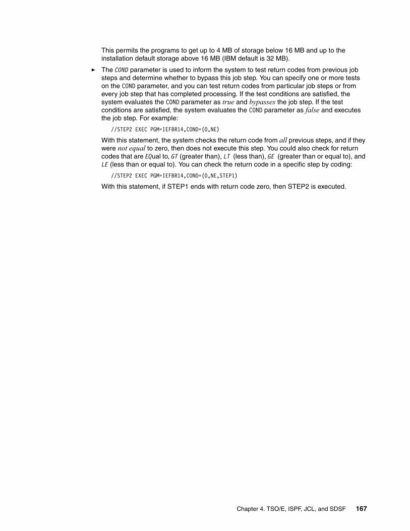
This permits the programs to get up to 4 MB of storage below 16 MB and up to the installation default storage above 16 MB (IBM default is 32 MB).
� The COND parameter is used to inform the system to test return codes from previous job steps and determine whether to bypass this job step. You can specify one or more tests on the COND parameter, and you can test return codes from particular job steps or from every job step that has completed processing. If the test conditions are satisfied, the system evaluates the COND parameter as true and bypasses the job step. If the test conditions are satisfied, the system evaluates the COND parameter as false and executes the job step. For example:
//STEP2 EXEC PGM=IEFBR14,COND=(0,NE)
With this statement, the system checks the return code from all previous steps, and if they were not equal to zero, then does not execute this step. You could also check for return codes that are EQual to, GT (greater than), LT (less than), GE (greater than or equal to), and LE (less than or equal to). You can check the return code in a specific step by coding:
//STEP2 EXEC PGM=IEFBR14,COND=(0,NE,STEP1)
With this statement, if STEP1 ends with return code zero, then STEP2 is executed.
Chapter 4. TSO/E, ISPF, JCL, and SDSF 167

4.48 JCL: EXEC statement
Figure 4-48 JCL: DD statement parameters
JCL: EXEC statementIt should be reiterated at this time that the program IEFBR14 actually does nothing. But it enables you to submit a valid job and the system can process the DD statements identified in the JCL. This allows you to allocate, delete, catalog, and uncatalog data sets by using a batch process. At job initialization, once the program IEFBR14 has been located, the system allocates the data sets specified in the DD statements, then the control is passed to program IEFBR14, which does nothing, and you get notified that your job is done.
The DD (data definition) statement describes a data set and specifies the input and output resources needed for the data set. The DD statement is highlighted in Figure 4-48 and identifies the data set we want to create.
This statement shows some of the parameters that can be coded in a DD statement.
DDname Used to give a name to DD. NEWDD is the name assigned in the example. The programs refer to DD names instead of dsnames. So, unless a program allocates dynamically, all ddnames referred by a program must be coded. For example, if a program in a step needs a file identified as OUTFILE, you must code a DD named OUTFILE, identifying the relevant data set. In the example, IEFBR14 does not use data sets, so you can choose any ddname you want.
DSN Used to identify the data set. In the example MIRIAM.IEFBR14.TEST.NEWDD is the data set.
DD statement
DD name
As referred by the program
DSN=
The data set name
168 ABCs of z/OS System Programming Volume 1

4.49 DD statement parameters: DISP, UNIT
Figure 4-49 JCL DD statement parameters: DISP, UNIT
DD statement: DISP parameterThe DISP parameter describes the status of a data set to the system and tells what to do with the data set after termination of the step or job. You specify this value for both normal and abnormal termination.
The first field identifies the STATUS of the data set and how to control access to it. It can be:
NEW Indicates the data set will be created and the job will have exclusive control of the data set. That means no other job can access this data set until the last step in this job that refers to this data set ends. NEW is the default.
OLD Indicates the data set exists and the job requires exclusive access to it.
MOD Indicates that if the data set exists, data will be appended to the end of the data set; otherwise, a new data set will be created. The job requires exclusive access to the data set.
SHR Indicates that the data set can be shared by other users.
The second field in the DISP parameter indicates to the system what to do with the data set when the step finishes NORMAL. It can be:
CATLG Catalog the data set
UNCATLG Uncatalog the data set
DELETE Delete the data set
DISP parameter
Control concurrent access to data set
What to do with the data set at end of processing
UNIT parameter
What type of device is the data set allocated on
Chapter 4. TSO/E, ISPF, JCL, and SDSF 169

PASS Pass the data set to the subsequent steps
KEEP Keep the data set intact
The third field in the DISP parameter indicates the ABNORMAL completion action. It can be: DELETE, CATLG, UNCATLG, or KEEP.
In the example, the status field specifies to create the data set; in the normal termination of the step, to catalog; and in abnormal termination to delete the data set. To delete a data set that exists you code its DSN and DISP=(OLD,DELETE,DELETE).
DD statement: UNIT parameterThis parameter identifies the device or type of device on which the data set will be allocated. You use this parameter to specify the number of devices to be used. If the data set exists, you only need to specify the device type if the data is not cataloged. Most installations now administer disk storage with the Storage Management System (DFSMS). With SMS, you do not need to use the UNIT parameter to specify a device for SMS-controlled data sets. Some common examples are:
UNIT=SYSDA Allocates the data set on a direct access device (DASD)
UNIT=3390 Allocates the data set on a 3390 type disk
UNIT=SYSALLDA Allocates the data set on a direct access device (DASD)
UNIT=TAPE Allocates the file on a TAPE device
170 ABCs of z/OS System Programming Volume 1

4.50 DD statement parameters: SPACE, LRECL, BLKSIZE
Figure 4-50 DD statement parameters: SPACE, LRECL, BLKSIZE
DD statement: SPACE parameterThe SPACE DD parameter is required for allocating data sets on DASD. It identifies the space allocation required for your data set. Before a data set can be created on disk, the system must know how much space the data set will require and how the space is to be measured. You can code it as follows:
SPACE=(type,(primary-qty,second-qty,directory))
Where type can be:
TRK Requests that space be allocated in tracks.
CYL Requests that space be allocated in cylinders.
block length Specify here the block length to request an allocation in number of blocks. Indicates that the values specified for primary and secondary allocations are block quantities, and directs the system to compute the number of tracks to allocate using a block length. For example, SPACE=(3150,(5,1)) means that the system will allocate five blocks, each block having 3150 bytes, as primary space and one block as secondary space.
record length Specifies that the average record length in bytes will be used to allocate space. This is only applicable if SMS is active and the AVGREC parameter is coded.
SPACE parameter
How much space to give the data set
LRECL parameter
What is the size of each record in the data set
BLKSIZE parameter
What is the block size (records in a block)
Chapter 4. TSO/E, ISPF, JCL, and SDSF 171

The system allocates DASD space in whole tracks. The number of tracks required depends on how the records are blocked.
primary-qty Specifies the initial allocation amount.
secondary-qty Specifies an additional allocation amount. The system does not allocate additional space until it is needed.
directory You must code for a partitioned data set, to indicate the number of blocks the system must reserve for the directory. Partitioned Data Sets Extended (PDSE) grow dynamically; if you specify directory size, SMS uses the size you specify only if you later convert the PDSE to a PDS. Omit this parameter for sequential data sets.
Some examples of how you can code are:
SPACE=(TRK,4) To allocate space to a sequential data set, requesting four tracks, only primary space.
SPACE=(CYL,(5,2)) To allocate space to a sequential data set, five cylinders as primary allocation space and two cylinders as secondary.
SPACE=(CYL,(10,,100) To allocate space to a partitioned data set, only primary allocation of 100 cylinders and 100 directory blocks.
LRECL and BLKSIZE parametersPrograms access data sets through ddnames. The ddnames are defined in the programs. Like them, data set characteristics like data set organization, logical record size and record size are also defined for the programs. During the allocation process you have to specify some of these characteristics. Some DD statement parameters you can use to specify the data set characteristics are:
LRECL Identifies the data set logical record size.
BLKSIZE Specifies the maximum length, in bytes, of a block.
RECFM Identifies the record format.
DSORG Identifies the data set organization. If you do not specify DSORG, the system uses the information in SPACE to determine if the data set should be sequential or partitioned
These parameters are part of Data set Control Block (DCB) information and can be coded in the JCL as follows:
// DCB=(LRECL=80,BLKSIZE=3120,RECFM=FB,DSORG=PO)
or as individual parameters, without the need to specify the DCB=(....) parameter, for example:
// LRECL=80,// BLKSIZE=3120,// RECFM=FB,// DSORG=PO
If BLKSIZE is not specified, the system will determine what it considers to be an optimum block size for the device type on which the data set will be allocated. For a data set with fixed record format (all records with same size), the BLKSIZE must be a multiple of LRECL. For variable record size, the BLKSIZE must be a multiple of the greatest record plus four.
172 ABCs of z/OS System Programming Volume 1

4.51 Submitting a job
Figure 4-51 Submitting a job
Submitting a jobYou have now created the data set MIRIAM.PRIVATE.JCLLIB, built your JCL member JOB1, and now you are ready to SUBMIT this job.
To submit the JCL stream, enter submit(sub) on the command line. The TSO/E command processor sends the JCL statements to JES.
After entering the command, you receive the following message indicating that your job was submitted successfully, as shown in Figure 4-51:
JOB jobname (jobnumber) SUBMITTED
IKJ56250I JOB MIRIAM2(JOB26044) SUBMITTED ***
Chapter 4. TSO/E, ISPF, JCL, and SDSF 173

4.52 Spool Display and Search Facility (SDSF)
Figure 4-52 Spool Display and Search Facility (SDSF)
Spool Display and Search Facility (SDSF)SDSF is a licensed program that helps authorized users efficiently monitor and control the operation of an MVS/JES2 system.
With SDSF you can authorize your MVS/JES2 users to:
� Control job processing (hold, release, cancel, and purge jobs)� Monitor jobs while they are being processed� Display job output before deciding to print it� Manage the system's workflow� Control the order in which jobs are processed� Determine the number of output jobs and the total number of records to be printed� Control the order in which output is printed� Control printers and initiators� View the MVS* system log online and use commands to search for specific information in
the log� Dynamically change job data set output descriptors� Issue JES2 and MVS commands that affect their jobs� Print selected lines of the JES2 output data set� Edit JCL direct from spool
Time Sharing Option/Extended - (TSO/E)
Interactive System Productivity Facility - (ISPF)
Job Control Language - (JCL)
Spool Display and Search Facility - (SDSF)
174 ABCs of z/OS System Programming Volume 1

4.53 SDSF: Panels hierarchy
Figure 4-53 SDSF: Panels hierarchy
SDSF: Panels hierarchySDSF consists of panels that provide immediate information about jobs, printers, queues, and resources in an MVS/JES2 system. The SDSF panel hierarchy is illustrated in Figure 4-53. From these panels, authorized users can enter SDSF commands to control the processing of jobs and the operation of system resources. Authorized users also can issue MVS and JES2 system commands from the SDSF panels.
PrimaryOptionMenu
SYSLOGPanel
DisplayActiveUsersPanel
InputQueuePanel
HeldOutputQueuePanel
Status Panel
Printer Panel
OutputQueuePanel
InitiatorPanel
JobData SetPanel
OutputDescriptorPanel
OutputData SetPanel
Chapter 4. TSO/E, ISPF, JCL, and SDSF 175

4.54 SDSF: Primary option menu
Figure 4-54 SDSF: Primary option menu
SDSF: Primary option menuIn this section we discuss the SDSF facility and how you can use its functions to monitor and manage your workloads. We see how SDSF can be used to display job input and output data, and purge (delete) jobs that are on the input, output, or held queues. We review the monitoring functions of SDSF that enable you to evaluate the current workload, and enable you to cancel, hold, or reschedule work.
SDSF can be invoked from ISPF menus, but the setting of the options is often customized by each site differently. You will have to review your site's ISPF menus to find the SDSF option. Alternatively, issuing the TSO SDSF command, from the Command ===> line invokes SDSF. After choosing this option, the panel you receive will be similar to the one in Figure 4-54. However, it may not have all the same options shown in the figure; the options vary according to the security level of the user. The authority to perform functions within these options also varies according to the security level of the user. It is possible to control most system functions by using the SDSF facility. The scope of the functions includes reviewing job output, controlling the processing of jobs (both their input and output), printer control, operator functions, and system administration.
176 ABCs of z/OS System Programming Volume 1

4.55 SDSF: Options menu
Figure 4-55 SDSF: Options menu
SDSF: Options menuBefore choosing any option, place the cursor in the menu action bar, select Options, and press Enter. Option 5 shows Set display values to OFF. If you then choose this option, the display options value will be set to OFF. You get the same result by issuing the SDSF command SET DISPLAY OFF in the COMMAND INPUT line.
You can customize your SDSF panels by choosing the View option in the action bar and then the Arrange option. You do that for each panel where the Arrange option is available and choose the fields in the order you want them. SDSF stores the information in your ISPF/PDF profile data set and uses them the next time you enter any SDSF options.
Chapter 4. TSO/E, ISPF, JCL, and SDSF 177

4.56 SDSF: Viewing the JES2 output files
Figure 4-56 SDSF: Viewing the JES2 output files
SDSF: Viewing the JES2 output filesYou can see the JES output data sets created during the execution of your batch job. They are saved on the JES spool data set. You can see the JES data sets in any JES queue: input (i SDSF option), execution queue (DA option), output queue (O option) or held queue (H option).
For output and held queues, you cannot see those JES data sets you requested to be automatically purged by setting a MSGCLASS out sysout CLASS that has been defined to not save output. Also, depending on the MSGCLASS you chose in the JOB card, the sysouts can be in the Output queue or in the Held queue.
The first screen shown in Figure 4-56 displays a list of the jobs we submitted and whose output we directed to the HELD (Class T) queue, as identified in the MSGCLASS=T parameter in the job card. In our case only one job has been submitted and executed. Therefore, we only have one job on the held queue.
Issuing a question mark (?) command in the NP column displays the output files generated by job 7359. The second screen shown in Figure 4-56 displays three ddnames: JES2 messages log file, JES2 JCL file, and JES2 system messages file. This option is useful when you are seeing jobs with many files directed to SYSOUT and you want to display one associated with a specific step. You issue an S in the NP column to select a file you want.
To see all files, instead of a question mark (?), type S in the NP column; the result is shown in Figure 4-57 on page 179.
Screen 1
Screen 2
178 ABCs of z/OS System Programming Volume 1

Figure 4-57 SDSF displaying the output job
Figure 4-57 on page 179 shows the output for our job. The most important things to note are:
1. The RC or Return Code value is 00 which indicates a successful completion of the step.
2. The COND CODE or Condition Code is 0000 which indicates a successful completion of the job.
3. The following messages show that the data set MIRIAM.IEFBR14.TEST.NEWDD was allocated on disk volume SBOXA7, and was cataloged.
IEF2851 MIRIAM.IEFBR14.TEST.NEWDD CATALOGEDIEF2851 VOL SER NOS= SBOXA7
J E S 2 J O B L O G -- S Y S T E M S C 6 4 -- N O D E 13.19.24 JOB26044 ---- WEDNESDAY, 27 AUG 2003 ---- 13.19.24 JOB26044 IRR010I USERID MIRIAM IS ASSIGNED TO THIS JOB. 13.19.24 JOB26044 ICH70001I MIRIAM LAST ACCESS AT 13:18:53 ON WEDNESDAY, AUGU13.19.24 JOB26044 $HASP373 MIRIAM2 STARTED - INIT 1 - CLASS A - SYS SC64 13.19.24 JOB26044 IEF403I MIRIAM2 - STARTED - ASID=0027 - SC64 13.19.24 JOB26044 - --TIMINGS (MINS.)--13.19.24 JOB26044 -JOBNAME STEPNAME PROCSTEP RC EXCP CPU SRB CLOCK13.19.24 JOB26044 -MIRIAM2 STEP1 00 9 .00 .00 .0013.19.24 JOB26044 IEF404I MIRIAM2 - ENDED - ASID=0027 - SC64 13.19.24 JOB26044 -MIRIAM2 ENDED. NAME-MIRIAM TOTAL CPU TIME= 13.19.24 JOB26044 $HASP395 MIRIAM2 ENDED ------ JES2 JOB STATISTICS ------ 27 AUG 2003 JOB EXECUTION DATE 11 CARDS READ 44 SYSOUT PRINT RECORDS 0 SYSOUT PUNCH RECORDS 3 SYSOUT SPOOL KBYTES 0.00 MINUTES EXECUTION TIME 1 //MIRIAM2 JOB 19,MIRIAM,NOTIFY=&SYSUID,MSGCLASS=T, // MSGLEVEL=(1,1),CLASS=A IEFC653I SUBSTITUTION JCL - 19,MIRIAM,NOTIFY=MIRIAM,MSGCLASS=T,MSGLEVE 2 //STEP1 EXEC PGM=IEFBR14 //*-------------------------------------------------* //* THIS IS AN EXAMPLE OF A NEW DATA SET ALLOCATION //*-------------------------------------------------* 3 //NEWDD DD DSN=MIRIAM.IEFBR14.TEST1.NEWDD, // DISP=(NEW,CATLG,DELETE),UNIT=SYSDA, // SPACE=(CYL,(10,10,45)),LRECL=80,BLKSIZE=3120 4 //SYSPRINT DD SYSOUT=T /* ICH70001I MIRIAM LAST ACCESS AT 13:18:53 ON WEDNESDAY, AUGUST 27, 2003 IEF236I ALLOC. FOR MIRIAM2 STEP1 IGD100I 390D ALLOCATED TO DDNAME NEWDD DATACLAS ( ) IEF237I JES2 ALLOCATED TO SYSPRINT IEF142I MIRIAM2 STEP1 - STEP WAS EXECUTED - COND CODE 0000 IEF285I MIRIAM.IEFBR14.TEST1.NEWDD CATALOGED IEF285I VOL SER NOS= SBOX38. IEF285I MIRIAM.MIRIAM2.JOB26044.D0000101.? SYSOUT IEF373I STEP/STEP1 /START 2003239.1319 IEF374I STEP/STEP1 /STOP 2003239.1319 CPU 0MIN 00.00SEC SRB 0MIN 00.00SIEF375I JOB/MIRIAM2 /START 2003239.1319 IEF376I JOB/MIRIAM2 /STOP 2003239.1319 CPU 0MIN 00.00SEC SRB 0MIN 00.00S
Chapter 4. TSO/E, ISPF, JCL, and SDSF 179

4.57 SDSF: Display Active Users (DA)
Figure 4-58 SDSF - Display Active Users (DA)
SDSF: Display Active Users (DA)SDSF provides the ability to monitor the current system workload. The DA command displays the active tasks and provides information about each task. This information includes CPU usage for each task, the amount of CPU time that a task has used, and the Input/Output related EXCP statistics. Figure 4-58 displays some of the data that this facility captures. Press PF11 to move to the right and see all the available fields.
When you command DA OTSU, SDSF displays only TSO users, DA OJOB shows only the JES jobs running, and DA OSTC shows only the active started tasks.
SDSF provides action commands you can use in the NP column. For example, from the Active Users panel, a user can enter S in the NP column next to a job to look at the output data set for that job. SDSF displays the output data set on the Output Data Set panel. You may not have authority to issue some of the available commands. In this case, SDSF issues a message in the top right of the panel. When you choose an action command, SDSF issues the system command that corresponds to the action you chose.
To display which action commands can be used in an SDSF panel, issue the HELP command in each option panel. Then choose option 3 - Action characters. A panel listing all the action commands you can use in that option appears.
Display Filter View Print Options Help -----------------------------------------------------------------------------SDSF DA SC67 SC67 PAG 0 SIO 7 CPU 6/ 7 LINE 1-25 (64) COMMAND INPUT ===> SCROLL ===> PAGPREFIX=* DEST=LOCAL OWNER=* SORT=JOBNAME/A NP JOBNAME STEPNAME PROCSTEP JOBID OWNER C POS DP REAL PAGING SIO *MASTER* STC06373 +MASTER+ NS FF 1369 0.00 0.00 ALLOCAS ALLOCAS NS FF 190 0.00 0.00 ANTAS000 ANTAS000 IEFPROC NS FE 1216 0.00 0.00 ANTMAIN ANTMAIN IEFPROC NS FF 4541 0.00 0.00 APPC APPC APPC NS FE 2653 0.00 0.00 ASCH ASCH ASCH NS FE 267 0.00 0.00 BPXOINIT BPXOINIT BPXOINIT LO FF 315 0.00 0.00 CATALOG CATALOG IEFPROC NS FF 1246 0.00 0.00 CICSPAAY CICSPAAY CICS520 STC06504 STC NS FE 4330 0.00 0.00 CONSOLE CONSOLE NS FF 597 0.00 0.00 DFRMM DFRMM IEFPROC STC06363 STC NS FE 510 0.00 0.00 DFSMSHSM HSMSC67 DFSMSHSM STC13178 STC NS FE 6199 0.00 0.00 DUMPSRV DUMPSRV DUMPSRV NS FF 160 0.00 0.00 FTPDMVS1 STEP1 STC06477 STC LO FF 470 0.00 0.00 FTPDOE1 STEP1 STC06475 FTPDOE LO FF 469 0.00 0.00 GRS GRS NS FF 894 0.00 0.00 IEFSCHAS IEFSCHAS NS FF 25 0.00 0.00 IMWEBSUF IMWEBSUF WEBSRV STC15245 WEBSRV IN FE 15T 0.00 0.00
180 ABCs of z/OS System Programming Volume 1

4.58 Issuing MVS and JES commands
Figure 4-59 Using SDSF to issued MVS and JES Commands
Issuing MVS and JES commands If you are authorized, on the COMMAND INPUT ===> line of any SDSF panel you can issue any MVS or JES2 command following a slash (/). If the command is too long, type + and two more lines will appear to allow you to type the rest of the command. If you have authority, you can use the ULOG option to see only your commands and their response.
Proceed with caution in the SDSF DA panel: If you issue a C (Cancel) action command in the DA display it will cancel any task you select if you have the authority. Use this command with caution if you are displaying major production tasks. Commands issued in the DA display are issued against running tasks. Incorrect or careless use can cause major problems.
Chapter 4. TSO/E, ISPF, JCL, and SDSF 181

4.59 SDSF: Input queue panel
Figure 4-60 SDSF: Input queue panel
SDSF: Input queue panelThe input queue panel provides information about jobs, TSO users, and started tasks that are on the JES2 input queue or are being processed by the system. Users display this information by entering i on the command input line of any SDSF panel. An example of this panel is shown in Figure 4-60.
This figure shows only a subset of the fields of information that are available on the Input Queue panel. You can scroll right, left, up, and down throughout this panel. Also you can control the scroll using the SCROLL ===> field. You can use, for example, C (CSR), to better control the scroll.
182 ABCs of z/OS System Programming Volume 1

4.60 SDSF: Output queue panel
Figure 4-61 SDSF: Output queue panel
SDSF: Output queue panelThe SDSF O command displays the non-held output queue. The Output Queue panel provides information about output data sets for jobs, TSO users, and started tasks that are on a JES2 output queue. Users display this information by entering o on the command input line of any SDSF panel. An example of this panel is shown in Figure 4-61.
You might want to use the PREFIX command to limit the entries in the display. For example,
� PREFIX, with no parameter displays all jobs for which you are authorized.
� PREFIX MQ* displays all jobs that start with the name MQ.
� PREFIX M%%R* displays all jobs that begin with M and have R in the fourth position.
The default, when you first enter SDSF, is your logon ID prefix. If SDSF is not displaying what you expect, issue the SET DISPLAY ON command. This controls the display of values you have set for PREFIX, DEST, OWNER, SORT, and FILTER.
The following is an output display using prefix DB2*.
NP JOBNAME StepName ProcStep JobID Owner C Pos DP Real Paging SIO DB2GDBM1 DB2GDBM1 IEFPROC STC04424 STC NS FE 9826 0.00 0.00 DB2GDIST DB2GDIST IEFPROC STC04425 STC NS FE 2313 0.00 0.00 DB2GIRLM DB2GIRLM STC04423 STC NS FE 284 0.00 0.00 DB2GMSTR DB2GMSTR IEFPROC STC04422 STC NS FE 1887 0.00 0.00
DB2GSPAS DB2GSPAS IEFPROC STC04426 STC NS FB 982 0.00 0.00
Chapter 4. TSO/E, ISPF, JCL, and SDSF 183

4.61 SDSF: Held Output queue panel
Figure 4-62 SDSF: Held Output queue panel
SDSF: Held Output queue panelThe Held Output queue panel provides information about output that is being held on any JES2 output queue. Users display this information by entering h on the command input line of any SDSF panel. An example of this panel is shown in Figure 4-62. This figure shows only a subset of the information available on the Held Output queue panel. From this panel, a user can look at the output for a specific job and then decide to print or purge the output.
184 ABCs of z/OS System Programming Volume 1

4.62 SDSF: Status panel
Figure 4-63 SDSF: Status panel
SDSF: Status panelThe Status panel provides information about jobs, started tasks, and TSO users that are on any of the JES2 queues. Users display this information by entering st on the command input line of any SDSF panel. An example of this panel is shown in Figure 4-63. This figure shows only a subset of the fields of information available on the Status panel.
Chapter 4. TSO/E, ISPF, JCL, and SDSF 185

4.63 SDSF: Tutorial
Figure 4-64 SDSF: Tutorial
SDSF: TutorialYou can use the Tutorial Panel to get familiar with all the SDSF functions. This panel is displayed when you Enter the command tutor on the command line.
The tutorial shows you some basic functions of SDSF. Some parts of the tutorial ask you to enter information on simulated SDSF panels. These simulated panels respond to your input. Interacting with the simulated panels will help you learn how SDSF works. However, if you prefer, the system will provide the input on interactive panels if you simply press Enter twice. Except on the interactive tutorial panels, SDSF commands are not valid on tutorial or help panels.
186 ABCs of z/OS System Programming Volume 1

Chapter 5. z/OS delivery and installation
z/OS consists of base elements and optional features. The base elements deliver essential operating system functions. The optional features are orderable with z/OS, and provide additional operating system functions.
Because the base elements and optional features of z/OS are integrated into a single package with compatible service levels, you must install, with few exceptions, the entire z/OS product. You can install z/OS using one of several IBM packages.
This chapter presents the available z/OS delivery options to install z/OS, as follows:
� ServerPac
� CBPDO
� SystemPac
� SoftwareXcel
� Entry Server Offering
In addition, this chapter describes briefly the download process and installation steps for using the ServerPac installation option.
5
Note: When you order any one of the installation packages, you will receive a comprehensive installation guide, detailing the installation tasks step-by-step from the beginning of the installation until you IPL your system.
For example, if you choose the ServerPac installation package, you receive the ServerPac: Installing Your Order documentation that is tailored to your order for installation. This document is unique to your environment and is based on what you have ordered.
© Copyright IBM Corp. 2008. All rights reserved. 187

5.1 z/OS installation overview
Figure 5-1 System programmer installing z/OS
z/OS installation overviewPrior to z/OS, large applications ran on an MVS operating system that consisted of the Basic Control Program (BCP), the Data Facility Product (DFSMSdfp), and Job Entry Subsystem (JES2 or JES3), plus a collection of other software products that the applications required, such as Interactive System Productivity Facility (ISPF), Time Sharing Option/Extensions (TSO/E), and so forth. You traditionally ran these products at various release levels, using a “mix and match” approach.
With the introduction of z/OS, all these products were integrated into a single product. You no longer order new levels of some products but not of others; instead, you order and install an entire set of products integrated into one functionally rich operating system. Only those components, where you have the license to use them, are allowed to run. For z/OS components, this is documented in the IFAPRDxx member of SYS1.PARMLIB.
Copy or SMP/E
ServerPac
IEBCOPY
Fee-based
or
or
Install z/OS
SMP/E
CBPDO
SYSPROG
188 ABCs of z/OS System Programming Volume 1

5.2 z/OS release cycle
Figure 5-2 z/OS release cycle
z/OS release cycleThe release cycle of z/OS is a new release level every year. Therefore, you can expect to receive function in new levels of every release. Note that not every element and feature in a given release contains new function. However, those elements and features that do not receive new function have all eligible service included.
This predictable release cycle should reduce your planning time. Because each new level is comprehensively tested, the quality of the operating system is improved. After your initial migration is complete, you can expect simplified ordering, planning, and installing of the next z/OS release.
Note: In September 2004, IBM changed the release cycle of z/OS to an annual basis, shipping a new release of z/OS each September.
Also, the number of consecutive releases that you can operate in a sysplex is reduced from four to three.
6 mon
ths
September 2004
1 year
Chapter 5. z/OS delivery and installation 189

5.3 z/OS delivery options
Figure 5-3 z/OS package options
z/OS delivery optionsYou can install z/OS using one of several IBM packages. These two packages are available at no additional charge when you license z/OS:
1. ServerPac: This software delivery package consists of products and service for which IBM has performed the SMP/E installation steps and some of the post-SMP/E installation steps. You use the CustomPac Installation Dialog to install your system and complete the installation of the software it includes.
2. CBPDO: The Custom Built Product Delivery Option (CBPDO) is a delivery package that consists of uninstalled products and unintegrated service. You must use SMP/E to install the individual z/OS elements and features, and their service, before you can IPL.
Several fee-based options are available, including:
3. SystemPac: SystemPac offers the capability to build a system with integrated subsystems in either full volume dump/restore format or data set copy format. The full volume dump/restore format enables you to install z/OS without using the dialog. Installation is done via pack restore using DFSMSdss or FDR (if the vendor product is selected in the order).
SystemPac is designed for those who have limited skill or time to install or upgrade z/OS, but who want to install or upgrade to exploit z/OS functions in e-commerce or other areas. SystemPac tailors z/OS to your environment (such as DASD layout, migration of MSVCP/IOCP to IODF, and naming conventions) based on information provided to IBM. With this offering, selected non-IBM products can be integrated.
z/OSz/OS
ServerPack
CBPDOSystemPac
SoftwareXcel
Entry Server Offering
190 ABCs of z/OS System Programming Volume 1

4. SoftwareXcel: SoftwareXcel Installation Express (SIE) is available in the U.S. only, and provides pre-built z/OS system packages in full volume dump format, tailored to customer hardware and software configurations. SIE includes on-site planning, installation, and package testing.
5. Entry Server Offering: The Entry Server Offering, only available in selected countries, is a packaged solution that includes hardware, software, installation services, maintenance, and financing to help customers get current technology.
Chapter 5. z/OS delivery and installation 191

5.4 ServerPac service level
Figure 5-4 ServerPac service level
ServerPac service levelFor ServerPac orders, service is integrated with product code according to the following time-line:
� ServerPac is refreshed every month to pick up the most current Recommended Service Upgrades (RSUs).
� All products incorporate HIPER and PTF-in-error (PE) fixes that are available approximately one week before your order is received.
� Your ServerPac order also contains a service tape containing all unintegrated service that was available at the time your order was processed.
z/OSz/OS
PTFsPE HIPER
192 ABCs of z/OS System Programming Volume 1

5.5 CBPDO service level
Figure 5-5 CBPDO service level
CBPDO service levelRemember, the service in the CBPDO orders is not integrated. You must receive and apply the service during the installation process. The service that is shipped with every CBPDO order is as follows:
� Service for all products previously ordered, as reflected in the customer profile for the customer number used when the order was placed. You can specify the starting date for these PTFs at order time. The default starting date is the last time that customer number was used to order a CBPDO (product or service) for that system release identifier (SREL).
� Service for all products, elements, and features that you have ordered. This includes all PTFs that became available between product general availability and the time of your order that have not been incorporated in the product FMIDs.
Note: A Memo to Users Extension comes with CBPDO; it describes the source IDs for service delivered on the CBPDO tape.
SoftwareXcel
PTFs
memo PTFs
PTFs
PTFs
Chapter 5. z/OS delivery and installation 193

5.6 System and installation requirements
Figure 5-6 Determining the installation requirements
System and installation requirementsHaving an installation plan helps you ensure the software is able to meet your installation's functional requirements. Besides functionality, there are other issues to think about when planning to build a system. These additional considerations include:
� Hardware and software requirements, including non-IBM software compatibility
� Virtual storage mapping
� Application performance
� Building a minimum number of system software configurations
� Reducing installation and migration time
� Reducing the opportunities for error during migration
� Making it easier to manage the system after it is in production
� Minimizing migration actions for the people who use the system
How you choose to meet all these requirements can have a significant effect on how much work is required to perform the tasks associated with each stage. Keep all these additional requirements in mind when you are planning to build a new system.
SYSPROG
Installation requirements:
1. Virtual storage requirement2. Application performance3. Minimum number of software configurations4. Reducing installation and migration time5. Reduce errors during migration6. System management7. Migration tasks
194 ABCs of z/OS System Programming Volume 1

5.7 Reviewing your current system
Figure 5-7 Reviewing your current system for migration
Reviewing your current systemMore often than not, you are planning to migrate from your current z/OS system to the new release of z/OS. It is therefore very important to review the setup of your current environment while planning for the new system. Some of the things you should consider are:
� The system layout
� The catalog structure
� Data set naming conventions in your present environment
� Security software considerations
� New standards, if necessary
Depending on your order, the system target and distribution libraries may exceed more than one DASD volume, for example IBM 3390-3. You should define your new system layout to be prepared for future installation and easy cloning of your system. We recommend that you read “Recommended data set placement” on z/OS V1R8.0 and z/OS.e V1R8.0 Planning for Installation, GA22-7504, before defining where the following new data sets should reside:
� Target data sets
� Distribution libraries data sets
� Master catalog and user catalogs
� Dialog and order data sets
Data naming convention
Security software requirements
System layout
Catalog structure New standardsCurrent systemCurrent system
Chapter 5. z/OS delivery and installation 195

5.8 The driving and target system
Figure 5-8 Using the driving system to create the new system
The driving and target systemThe driving system is the system image (both the hardware and software) that you use to install your new system image, the target system. You log on to the driving system and run jobs there to create or update the target system. Once the target system is built, it can be IPLed on the same hardware (same LPAR or different LPAR on the same processor) or on different hardware than that used for the driving system.
To prepare the driving system before building the target system, you need to perform the following tasks:
� Identify the software requirements for the driving system according to the delivery package you are using, for example, ServerPac.
� Identify the hardware requirements for the driving system.
You are also required to do some preparations for the target system:
� Choose the software products to install and identify requisites.� Order z/OS and related IBM products.� Identify the hardware requirements for the target system.� Identify the service needed for the target system.� Decide whether to use the existing JES2 or JES3 with the new z/OS release.
For more information on each of the requirements for both the driving and target system, see z/OS Planning for Installation, GA22-7504, for the z/OS release that you are installing.
Target System
Driving System
Target System
LPAR1
Build
LPAR2
196 ABCs of z/OS System Programming Volume 1

5.9 z/OS installation using ServerPac
Figure 5-9 Installation tapes for ServerPac
z/OS installation using ServerPacYour z/OS ServerPac order contains an ISPF dialog that you use to install z/OS. This dialog is called the CustomPac installation dialog because it is used to install all of IBM's CustomPac offering.
Before you begin the installation, you should:
� Review the contents of the ServerPac shipment that you received from IBM by checking the packing slip to make sure that you have a complete set of installation tapes and documentation.
� Make sure your user ID has ALTER authority for the following high-level qualifiers:
– CPAC
– SYS1
– All product-specific high-level qualifiers for products that come with your package. You can find a listing of all qualifiers by using the A-ALIAS option of the dialog, or refer to Product Information in the Appendix of the document IBM ServerPac Using the Installation Dialog, SA22-7815.
� During of the job phase of the installation process you may need RACF SPECIAL authority or equivalent if you use other security software.
� If you decided to use SMS to manage data sets in your order, your user ID needs READ access to FACILITY class profile STGADMIN.IGG.DIRCAT.
z/OS V1R8
System and Distribution Tapes
Service Tape
RIM Tape
Chapter 5. z/OS delivery and installation 197

5.10 Installing the CustomPac dialogs
Figure 5-10 Installing the CustomPac dialogs
Installing the CustomPac dialogsThe first step in installing z/OS is to install the CustomPac dialogs from the RIM tape on your driving system. Once they are installed, the dialogs do not have to be reinstalled with every order. They are auto-upgraded whenever you get a new order. Version checking invokes the update of the dialogs during the CustomPac RECEIVE function.
Steps to install the CustomPac dialogs:
1. Define the HLQ for the CustomPac data sets (called master dialog data sets) pointing to a user catalog accessible by both the driving and the target systems; for example, SERVRPAC.
Since the dialogs are permanently installed at your installation, you should not specify the IBM-supplied order number as the CustomPac qualifier.
2. If you intend to use SMS-managed dialog data sets, assign them to a management class that does allow migration, unless SMS and HSM environments will be shared between driving and target systems.
3. Unload the LOADRIM job from SYS1.orderid.DOCLIB data set the RIM tape, as shown in Figure 5-10.
4. The LOADRIM job contains steps to:
� Delete previous CustomPac dialog data sets.� Unload master dialog data sets.� Allocate an order inventory data set to contain control information for all shipped
ServerPac orders.
HLQ for the CustomPac data setsCustomPac data sets placementExtract LOADRIM Customize and run LOADRIM Start the CustomPac dialogs
//EXTRACT JOB <JOB statement info goes here...> //* //STEP01 EXEC PGM=IEBCOPY //* //SYSPRINT DD SYSOUT=* //* //IDOC DD DISP=SHR,DSN=SYS1.orderid.DOCLIB,LABEL=(06,SL),// VOL=SER=tapeser,UNIT=tapeunit //ODOC DD DSN=work.library.jcl, // DISP=(NEW,CATLG,DELETE), // VOL=SER=volser,UNIT=SYSALLDA, // SPACE=(9600,(240,30,20)) //* //SYSIN DD * COPY INDD=IDOC,OUTDD=ODOC S M=LOADRIM /*
198 ABCs of z/OS System Programming Volume 1

5.11 The RIM tape samples
Figure 5-11 Using the CustomPac dialogs
The RIM tape samplesThe RIM tape contains sample procedures, JCL, jobs, and CLISTs. They are in SYS1.orderid.DOCLIB. You can unload and modify these samples for your installation, as shown in Table 5-1.
Table 5-1 Useful samples from the RIM tape
Name Description
LOADRIM LOADRIM is the JCL to unload files from tape and set up the installation dialog. When you edit the LOADRIM sample JCL, you can choose the name of the master data sets, the unit name of your tape drives, and the VOLSER of the DASD which receives the installation dialog’s data sets.
SETUP This is a sample LOGON procedure which includes the CustomPac dialog ISPF libraries.
CPPCSAMP This sample CLIST can be used to set up the environment instead of modifying the LOGON procedure. CPPCSAMP uses LIBDEFs and should be the preferred method to allocate the CustomPac libraries and start the dialog.
CPPINIT With the CPPINIT CLIST, you can set up the environment from native TSO.
PRTDOC This sample job prints the CustomPac Installation dialog reference manuals.
z/OS V1R8
RIM TapeCPPCSAMP CLISTLOGON ProcedureLOADRIM
Chapter 5. z/OS delivery and installation 199

5.12 Starting the CustomPac dialogs
Figure 5-12 CustomPac dialogs
Starting the CustomPac dialogsThe CustomPac dialogs are now installed. To access the dialogs, we recommend that you:
1. Customize the CPPCSAMP CLIST, changing the custompac.qualifier according to the qualifiers of the master dialogs data sets.
2. Save the customized clist.
3. Go to TSO/ISPF, option 6 and execute the new CLIST:
exec 'DATA.SET.NAME(CPPCSAMP)'
Where DATA.SET.NAME is the partitioned data set where you saved the CLIST and CPPCSAMP is the member name where you saved the customized CPPCSAMP CLIST.
Figure 5-13 on page 201 shows the panel you receive when you start the CustomPac dialogs.
Allow customization of order
Generate jobstream to install order
Provide problem diagnosis
Provide order management tools
CustomPac code ISPF dialog elements
CustomPac CustomPac DialogsDialogs
200 ABCs of z/OS System Programming Volume 1

5.13 Receiving the ServerPac order
Figure 5-13 CustomPac primary menu
Receiving the ServerPac orderBefore you use the dialog to install your order, perform the following tasks:
� Review the recommended actions in “z/OS installation using ServerPac” on page 197. � Be familiar with the dialogs. Consult IBM ServerPac Using the Installation Dialog,
SA22-7815, in particular the following sections:– “Features of the Dialog Panels” describes the ISPF Edit settings used, the available
primary and line commands, language setting, dynamic help, and diagnostic messages.
– “Working With Your Order: An Overview of the Dialog Activities” summarizes the steps to install a ServerPac order.
– “Using the Installation Menu” explains the dialog functions provided.
After you start the dialog, the first thing to do is receive the order. This is done when you choose option R in the primary menu panel, as shown in Figure 5-13. Receiving the order means you copy the order from tape, or from an FTP server, or from a file system on the driving system to DASD. This unloads the control tables and installation jobs from the shipment medium to your DASD.
Note: HELP (PF1) is available on any panel. The HELP key is a very useful online help facility that explains every panel function in detail. Some panels have PRIM and LINE commands available. Using the HELP key allows you to get a description and example of how to use the commands.
Chapter 5. z/OS delivery and installation 201

5.14 Order Receive panel
Figure 5-14 Order Receive
Order Receive panelBecause you chose option R, you will receive the panel shown in Figure 5-14.
The following information is entered on the Order Receive panel:
Receive the order from Here you specify the source medium of your order. It is still possible to receive from tape, but today other media are supported. These are Internet (Server), or from a USS file system.
Order Number Your specific IBM-supplied order number, which is listed on the cover of the order documentation.
Data Set Qualifiers The HLQ used to allocate the order installation data sets. We recommend you include the order number as part of the qualifier.
Volume Serial Enter the volume serial number of the DASD volume that will receive the order data sets.
STORCLAS If you have an SMS-managed environment, enter a valid storage class for the order data sets.
Dialog CLIST Rec. Fm. Dialog CLISTs for the order are supplied in both FB and VB formats. FB is the default.
Press Enter after you have filled out the order details. Depending on your choice in the Receive order from field, you will get different follow-on panels. Based on the selection in Figure 5-14, the next panel looks as shown in Figure 5-15 on page 203.
202 ABCs of z/OS System Programming Volume 1

5.15 Receive an order from tape
Figure 5-15 Receive order from tape panel
Receive an order from tapeIf you chose T in the previous panel, you will get the receive order from tape panel, as shown in Figure 5-15. In this panel, enter the tape volume serial number of the first tape of your ServerPac delivery. This is the RIM tape. Ensure that you enter the correct volume serial number, because there is no validation made through the CustomPac dialogs. You also must enter a generic or esoteric tape unit name. The default is 3590. You can obtain this information from your I/O configuration.
After pressing Enter you will be guided to the Edit JOB statement panel, shown in Figure 5-16 on page 204.
Chapter 5. z/OS delivery and installation 203

5.16 Edit JOB statement panel
Figure 5-16 Edit JOB statement panel
Edit JOB statement panelThis is an informational panel. After you press Enter, you will see the ISPF editor with the job statements for the receive process. At that point, you can make changes to the job statements to meet your requirements.
After you perform that customization, press the PF3 key, which leads you to Figure 5-17 on page 205.
204 ABCs of z/OS System Programming Volume 1

5.17 Edit RECEIVE job panel
Figure 5-17 Edit RECEIVE job panel
Edit RECEIVE job panelAfter pressing Enter on this panel, you receive the next ISPDF editor screen, where the generated RECEIVE job is listed. At this point, you can review it and possibly make final changes to the job.
When you submit the job from the editor, it performs the following steps:
� Verifies the status of the CustomPac data sets
� Possibly, deletes duplicate data sets
� Allocates CustomPac order data sets (VSAM and non-VSAM)
� Copies CustomPac data sets from the RIM tape to the specified DASD volume
� Updates the existing order inventory for the next steps
If you run these steps successfully, you are able to proceed with the installation dialog.
Chapter 5. z/OS delivery and installation 205

5.18 Selecting an order to install
Figure 5-18 Selecting an order to install panel
Selecting an order to installAfter you finish the order receive function, Enter I on the CustomPac primary menu, shown on Figure 5-13 on page 201. This leads you to Figure 5-18.
On the order installation panel, you may have a number of already received or installed CustomPacs. Select the one you just received to proceed with the installation process. If it is your first ServerPac installation, you may only select this order number.
Select S to go into the installation dialog.
206 ABCs of z/OS System Programming Volume 1

5.19 Installation dialog
Figure 5-19 Installation dialog
Installation dialogAfter selecting a ServerPac order to install, the main installation dialog panel is invoked. When this panel is shown for the first time during a ServerPac order installation, the only option available is:
C Option C on this panel allows you to select a configuration for merging an initial installation. If this is your first CustomPac installation, the Create Configuration panel appears.
The other options are marked with an asterisk (*) and become available as long as the previous function has successfully finished. Now, choose option C.
Chapter 5. z/OS delivery and installation 207

5.20 Choosing the installation type panel
Figure 5-20 Create Configuration: Choosing the Installation Type
Choosing the installation typeWhen you use the dialog to select an order, its shipped configuration is added to the dialog. You must select and create a configuration to start the installation. Option F installs a complete z/OS system. It installs all data sets needed to IPL, log on to the target system, and run a z/OS image to complete other installation and customization tasks, including:
1. System software and related data sets, like distribution, target, SMP/E libraries, and so forth.
2. System data sets like page data sets, system control files, and master catalog.
Because IBM creates a working set of operational data sets for you, a full system replacement helps assure a successful first IPL.
Choose Full System Replacement, Option F.
208 ABCs of z/OS System Programming Volume 1

5.21 Selecting a JES for the configuration
Figure 5-21 JES Element Selection panel
Selecting a JES for the configurationSelect at least one JES element for installation: JES2 (and SDSF) or JES3. If your installation requires both JES elements to be installed, you can select BOTH.
For each JES element you select, specify whether the dialog is to merge the SMP/E zones of the JES element with the Base Control Program (BCP) zones. When you merge a JES element with the BCP zone, no separate zone is created for the JES element.
If you plan to migrate to subsequent releases of JES2 (and SDSF) or JES3 when you migrate to the next level of z/OS, we recommend that you specify Y on this panel to merge the selected JES elements into the BCP zone.
However, if you plan to stage your z/OS and JES migrations separately, do not merge zones.
Once the panel information is filled out, press Enter. The Create Configuration panel is displayed.
Chapter 5. z/OS delivery and installation 209
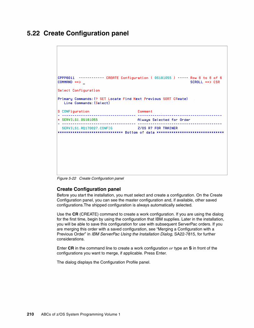
5.22 Create Configuration panel
Figure 5-22 Create Configuration panel
Create Configuration panelBefore you start the installation, you must select and create a configuration. On the Create Configuration panel, you can see the master configuration and, if available, other saved configurations.The shipped configuration is always automatically selected.
Use the CR (CREATE) command to create a work configuration. If you are using the dialog for the first time, begin by using the configuration that IBM supplies. Later in the installation, you will be able to save this configuration for use with subsequent ServerPac orders. If you are merging this order with a saved configuration, see “Merging a Configuration with a Previous Order” in IBM ServerPac Using the Installation Dialog, SA22-7815, for further considerations.
Enter CR in the command line to create a work configuration or type an S in front of the configurations you want to merge, if applicable. Press Enter.
The dialog displays the Configuration Profile panel.
210 ABCs of z/OS System Programming Volume 1
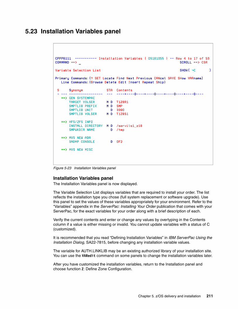
5.23 Installation Variables panel
Figure 5-23 Installation Variables panel
Installation Variables panelThe Installation Variables panel is now displayed.
The Variable Selection List displays variables that are required to install your order. The list reflects the installation type you chose (full system replacement or software upgrade). Use this panel to set the values of these variables appropriately for your environment. Refer to the “Variables” appendix in the ServerPac: Installing Your Order publication that comes with your ServerPac, for the exact variables for your order along with a brief description of each.
Verify the current contents and enter or change any values by overtyping in the Contents column if a value is either missing or invalid. You cannot update variables with a status of C (customized).
It is recommended that you read “Defining Installation Variables” in IBM ServerPac Using the Installation Dialog, SA22-7815, before changing any installation variable values.
The variable for AUTH.LINKLIB may be an existing authorized library of your installation site. You can use the VARedit command on some panels to change the installation variables later.
After you have customized the installation variables, return to the Installation panel and choose function Z: Define Zone Configuration.
Chapter 5. z/OS delivery and installation 211

5.24 Define ZONE Information panel
Figure 5-24 Define ZONE Information panel
Define ZONE Information panelThis brings you to the Define ZONE Information panel, where you can define your SMP/E zone configuration. This panel is displayed even if you do not plan to change the shipped zone names.
You can change the zone names to the names you want. The nickname is used to pair them together.
For more information, refer to ServerPac: Installing Your Order.
After your changes, if any, return to the Installation panel and enter M to begin the next dialog function.
212 ABCs of z/OS System Programming Volume 1

5.25 Modify System Layout Options panel
Figure 5-25 Modify System Layout Options panel
Modify System Layout Options panelDefining the target system layout is one of the most important steps during order installation. During this part of the dialog, you create the data set layout for your new system. After you have modified this configuration, you can save it for merging with future ServerPac installations. You can create the new data set layout in one of three ways:
� Option A: Recommended System Layout to make the dialog automatically assign the target and DLIB data sets in the configuration to physical volumes. The dialog does not automatically assign any SMS-managed data sets in the configuration.
� Option C, View and Change, to assign your order's data sets to volumes by displaying groups of data sets, and using the CHANGE PVOL command to specify their placement on physical volumes.
� Other options (D, M, S, U, V, L, and P) to assign your order's data sets to logical volumes and then assign those logical volumes to physical volumes (DASD).
The recommended system layout provides a foundation for the ongoing growth and maintenance of your system. When you group your system's data sets by their content and importance to your installation, you help to minimize the complexity of future installations.
Read and use the section “Modifying the System Layout” in IBM ServerPac Using the Installation Dialog, SA22-7815. The ServerPac: Installing Your Order publication that comes with your order also contains all information relating to the products to be installed.
Chapter 5. z/OS delivery and installation 213

5.26 Summary of Features/Elements panel
Figure 5-26 Summary of Features/Elements panel
Summary of Features/Elements panelWhen you select Option P of the Modify System Layout Options panel, the Summary of Features/Elements panel shown in Figure 5-26 is displayed.
This panel allows you to manually customize individual data sets, logical volumes, and physical volumes. The panel lists the products, features, and elements shipped in your ServerPac order, and the following CustomPac-specific data set groups:
� CustomPac SREL-specific SMP/E data sets � CustomPac operational and sample data sets � CustomPac JES2 data sets � CustomPac JES3 data sets � CustomPac SMP/E data sets
The panel shows primary and line commands you can issue to perform the actions you need to customize volumes and data sets names. For example, the Select command entered next to a product displays the Logical Volume By FEATURE/ELEMENT panel for the selected product, where you can use the line command Assign to assign all data set profiles for the selected logical volume to a different logical volume.
The D line command returns the Summary of Data Sets panel shown in Figure 5-27 on page 215.
214 ABCs of z/OS System Programming Volume 1

5.27 Summary of data sets of a feature or element
Figure 5-27 Displaying data sets of a feature or element
Summary of data sets of a feature or elementUse the Summary of Data Sets panel to do any of the following:
� Merge or unmerge ServerPac-shipped data sets (you cannot merge or unmerge user-defined data sets).
� Modify the attributes of particular data sets or modify their space information.
� Make global changes to multiple data sets.
� Write a list of the data sets in the ISPF LIST data set or a user-defined file.
The Change primary command allows you to make global changes to data set profiles. For example, you can change the HLQ for those product data sets. The line command S allows you to change data set name, logical volumes space, and BLKSIZE definitions for a specific data set profile.
Chapter 5. z/OS delivery and installation 215

5.28 Summary of Physical Volumes panel
Figure 5-28 Summary of Physical Volumes
Summary of Physical Volumes panelBefore you leave the Modify System Layout main panel, you should enter the SUMP PRIM command, which displays a summary of the physical volumes.
When one of your physical volumes becomes over-allocated, the following message appears on the panel:
| CPP0605005S At least ONE PHYSICAL Volume is OVER ALLOCATED |
This condition is also shown by the <<<<<<< next to the physical volume names.
By using the dialogs previously described, you are able to modify the system layout and correct the over-allocation of physical volumes.
216 ABCs of z/OS System Programming Volume 1

5.29 Creating the recommended system layout
Figure 5-29 Automatic data set assignment panel
Creating the recommended system layoutWhen you select option A, the Recommended System Layout, the panel shown in Figure 5-29 is displayed. The dialog automatically assigns some or all of the target and DLIB data sets in your order to DASD volumes based on the following considerations:
� Whether the data set is a target data set or a DLIB data set
� Whether the data set must reside on the IPL volume
� The type of data in the data set: panels, messages, load modules, and so on
� If the data set should reside on a particular volume in the configuration; for example, the first volume or one of the last volumes
The dialog does not automatically assign an order's operational data sets or any of the sample CustomPac data sets. You must place these data sets yourself.
The Default Device Type field specifies the type of device to be used if the dialog creates more volumes for data set assignments. Enter a question mark (?) in the Default Device Type field and press Enter to see a list of other available devices. A configuration can include more than one device type.
Choose ALL when you are installing a ServerPac order for the first time, or if you are not using a saved configuration as the basis of your new system. This approach creates a new configuration based only on the new order to be installed.
Chapter 5. z/OS delivery and installation 217

5.30 Current Volume Configuration panel
Figure 5-30 Automatic Data Set Assignment: Current Volume Configuration panel
Current Volume Configuration panelAfter you select a setting for automatic assignment, the dialog displays the current volume configuration, as shown in Figure 5-30.
As shipped by IBM, a new configuration consists of a target volume, MVSRES; a DLIB volume, MVSDLB; and a catalog volume, MVSCAT. Because MVSCAT contains only operational data sets, this volume is excluded from automatic assignments, and therefore is not shown in the panel display.
In this panel you use line commands in the S column for the following purposes:
� S to select a volume to change� L to list data sets currently assigned to a volume� I to insert more volumes� X to make exceptions to volume assignments. This command has a different use
according to the scope of automatic assignment (ALL, NEW, or PARTIAL) selected on the panel shown in Figure 5-29 on page 217.
� M, A or B to move volumes in the order in which you want them to be used.
If you plan to rename these volumes, select the volumes now through line command S and rename them as needed. Later, when the new configuration is created, it is more difficult to rename these volumes. When you select S the panel shown in Figure 5-31 on page 219 is shown.
218 ABCs of z/OS System Programming Volume 1

5.31 Display and change volume attributes panel
Figure 5-31 Display and change volume attributes panel
Display and change volume attributes panelBe aware that if you keep the value Y in the Initialize Volume field, you will initialize the volume during the installation process.
To save your changes to the volume, press the Enter key and you return to the Current Volume Configuration display.
After you have customized the system layout, return to the Installation panel for the next function.
Chapter 5. z/OS delivery and installation 219
5.32 Define alias-to-catalog relationships
Figure 5-32 Define CATALOG Dataset Names panel
Define alias-to-catalog relationshipsFrom the Installation Menu, enter A, Define Alias to Catalog Relationships. In this option, you specify the catalog data set name for each alias. The dialog and the installation process for ServerPac use the standard order of catalog search when defining and locating data sets. Therefore, there must be an alias in the target system master catalog for each high-level qualifier used for data sets that are to be cataloged in a user catalog. Also, there must be aliases in the driving system master catalog for the system-specific aliases (SSAs) you chose to use when installing the order.
Before you begin to define the alias-to-catalog relationships and system-specific alias-to-catalog relationships, you should read Chapters 9 and 10 in IBM ServerPac Using the Installation Dialog, SA22-7815, to become familiar with using system specific-aliases and the catalog structure. Also, those chapters contain worksheets models you can use to plan:
� The catalog and alias names, and their relationships� The catalog names and their associated SSAs
Use the ALIAS to CATALOG panel to specify which HLQ you want to be associated with a catalog. An M in the STA column indicates that this alias name must be associated with a master catalog. If you find ??????? in the TARGET System Catalog DSName field, it indicates that there is no catalog defined yet. This function allows you also to insert additional user-defined alias names and catalogs. After specifying the alias-to-catalog relationship, you can select SSA on the Installation panel, which leads you to the SSA-to-Catalog panel shown in Figure 5-33 on page 221.
220 ABCs of z/OS System Programming Volume 1

5.33 Define system-specific alias (SSA)
Figure 5-33 Defining system-specific aliases
Define system-specific alias (SSA)Many of the data sets in your new order already exist on your driving system. While your order's data sets are intended for creating a new target system, there is a period during installation in which jobs running on your driving system must be able to locate the target system's data sets.
Because many of these data set names already exist in your master catalog, ServerPac requires a way to find the data sets in the normal order of catalog search. This way, jobs on the driving system can locate the target system's data sets without disturbing the operation of the driving system. Without such a method, ServerPac could not build a target system with any data sets that were already cataloged and allocated on your driving system.
In the Define SSAs function of the dialog, you define temporary high-level qualifiers (HLQs) for the target system data sets. During the installation, your order's data sets are cataloged with the temporary HLQs. To direct the catalog entries to the proper catalog, the temporary HLQs are defined as aliases in the driving system's master catalog. Thus, these alternate HLQs are called system-specific aliases or SSAs. Later, during the installation, jobs rename the target system's data sets to their true names, and an optional job is provided for you to remove the SSAs.
The SSAs you specify here are used to create alias entries for these catalogs in the driving system's master catalog. The process you use to define SSAs depends on your installation type: full system replacement or software upgrade. For a full system replacement, define your SSA and catalog with the panel shown in Figure 5-34 on page 222.
Chapter 5. z/OS delivery and installation 221

5.34 Define SSA and CATALOG Data panel
Figure 5-34 Define SSA and CATALOG Data
Define SSA and CATALOG Data panelThe panel shown in Figure 5-34 is displayed when you use full system replacement, option F on the panel shown in Figure 5-20 on page 208. The panel fields are as follows:
Catalog: Name of the catalog for which an SSA is to be defined.
Type: The catalog type. MCAT indicates a master catalog; UCAT indicates a user catalog.
Define the following fields:
SSA Name: Set this value to Y (yes) to define a new SSA in the driving system's master catalog. Set this value to N (no) if the SSA is already defined in the driving system's master catalog. If you set the Allocate Catalog field to Y, you must set the Define SSA field to Y.
Allocate Catalog: Specifies whether the catalog does not yet exist on the target system, and is to be physically allocated (Y); or N if the catalog already exists on the target system.
Catalog Volume, Primary Space and Secondary Space:
Specifies allocation parameter for the catalog.
This is the end of the customization steps for the ServerPac. You are now ready to run the supplied installation jobs. From the Installation Menu, enter I and the panel in Figure 5-35 on page 223 is shown.
222 ABCs of z/OS System Programming Volume 1

5.35 Job Selection List panel
Figure 5-35 Job Selection List panel
Job Selection List panelThere are three types of components shown on the Installation Jobs panel:
SRC Source data such as parameter listsDOC DocumentationJOB Executable JCL
The installation steps are grouped into the following sections:
� Package-specific installation� Product-specific installation� Post-installation� Additional post-installation� Customization section� Installation verification section� Cleanup jobs� Migration section� Customer-specific customization
When you enter the Installation Jobs panel for the first time, the installation jobs have still not been generated. All installation jobs are generated using ISPF tailoring services. We recommend that you use the GENSKEL command to tailor all of the installation jobs at one time. When GENSKEL completes, the dialog saves the jobs in a backup data set. For more information about the commands you can use on this panel, refer to IBM ServerPac Using the Installation Dialog, SA22-7815, Chapter 11.
Chapter 5. z/OS delivery and installation 223

5.36 GENERATE File Tailored Installation Jobs panel
Figure 5-36 GENERATE File Tailored Installation Jobs panel
GENERATE File Tailored Installation Jobs panelWhen you enter the GENSKEL command, the panel shown in Figure 5-36 is displayed.
The GENSKEL command submits a batch job, which generates all the installation jobs. Each job is stored in the SCPPBENU data set that is provided through the ServerPac RECEIVE process.
For z/OS orders, GENSKEL processing can take as much as 30 minutes or longer to complete. Subsystem orders might need only several minutes to complete.
The installation jobs should be submitted in sequence. Always read the DOC section before you select and submit the related jobs. All installation steps and jobs are also described in ServerPac: Installing Your Order.
File-tailored jobs might already exist in the SCPPBENU data set. Set the Replace Job field to Y to replace jobs; set the field to N to preserve them.
224 ABCs of z/OS System Programming Volume 1

5.37 Displaying the processing log
Figure 5-37 Processing Log Panel: SUMMARY command
Displaying the processing logThis panel lists the jobs that were submitted from the job stream and their respective return codes. If output logging is active, you can browse the job output. After a job's completion, the job output can be seen using the Output line command.
The job copying data sets to SystemPac Vols (RESTORE) may run for a long time, depending on the number of products your ServerPac order contains. You should have two tape drives and all the tape cartridges shipped with your order available before you start the RESTORE job.
Post-installation and customization is product- and installation-dependent, and should be related to your specific requirements.
After the installation jobs have completed, you should be able to IPL and test your new z/OS system.
Chapter 5. z/OS delivery and installation 225

5.38 Save Configuration panel
Figure 5-38 Save Configuration panel
Save configuration panelAfter you install a ServerPac order, you can use the Save Used Configuration function of the dialog to save your work configuration. Doing so can help you save time in installing subsequent ServerPac orders. Rather than manually re-entering all of the data required for each new order, you can merge the saved configuration with the new order and avoid much of the data entry.
Specify the HLQ for the configuration. The configuration data set is appended with either of the following low level qualifiers:
� SCPPSENU: For skeleton libraries
� SCPPTENU: For table libraries
If the libraries do not exist, the dialog prompts you to confirm that the libraries can be allocated. If the libraries already exist, a new panel is displayed to confirm the deletion of the old libraries.
226 ABCs of z/OS System Programming Volume 1

5.39 IBM software ShopzSeries
Figure 5-39 ShopzSeries start menu
IBM software ShopzSeriesIBM ShopzSeries is a Web-based application, where you as a registered customer can perform a number of tasks related to IBM System z software ordering and tracking.
In this section you will learn how you can place z/OS software orders using IBM ShopzSeries. You will also learn how you can handle the CustomPac receive process with a downloaded ServerPac.
You can reach the start page by entering the following link:
https://www14.software.ibm.com/webapp/ShopzSeries/ShopzSeries.jsp
You must sign in using your IBM ID and password.
Chapter 5. z/OS delivery and installation 227

5.40 Shop zSeries order process
Figure 5-40 Shop zSeries order process menu
Shop zSeries order processAfter you are logged on to the ShopzSeries application, click My Orders on the left side of the Web page and the screen shown in Figure 5-40 will be displayed.
When you create a new order, you must enter the following information into the window:
� Your customer number
� Operating environment (in this case, z/OS)
� Package category (in this case, Products)
After entering this information, press Continue to proceed.
0000001
228 ABCs of z/OS System Programming Volume 1

5.41 Specify order basics step 1 of 8
Figure 5-41 Specify order basics menu
Specify order basics step 1 of 8On this panel, you must choose the package type you want to order. You can either select products via CBPDO or a ServerPac for system replacement.
For our installation process, we selected system replacement and pressed Continue.
0000001
Chapter 5. z/OS delivery and installation 229

5.42 Select hardware systems step 2 of 8
Figure 5-42 Select hardware systems menu
Select hardware systems step 2 of 8In this step you find the installed base of your zSeries hardware systems. You must select one or more systems where the appropriate software licenses exist, by checking the Select box (or boxes). Then press Continue (not shown here) to proceed to the next step.
0000001
230 ABCs of z/OS System Programming Volume 1

5.43 Report installed software step 3 of 8
Figure 5-43 Report installed software menu
Report installed software step 3 of 8If you order a ServerPac electronically, you may decide to upload a report that contains the installed base of your software that runs under z/OS. This report is used to verify your actual product status, software upgrade paths, and missing prerequisites. If you use this option, the order process will consider this and give you the latest releases of all of your installed components. (In our case, we did not use this option.)
To proceed, press Continue.
Chapter 5. z/OS delivery and installation 231

5.44 Shop for products step 4 of 8
Figure 5-44 Shop for products menu
Shop for products step 4 of 8In step 4 of the order process, you can select the products you need. To order a z/OS ServerPac, you must fill the three pull-down menus with valid values, as explained here:
Group Enter the kind of operating system you want to order.
Language Select from the list of available languages for the selected product.
Filter Show all available products from the selected operating system, or select only a subset.
After you make your selection, press Show catalog to see the components in detail. The list is then presented in 5.45, “Shop catalog” on page 233.
232 ABCs of z/OS System Programming Volume 1
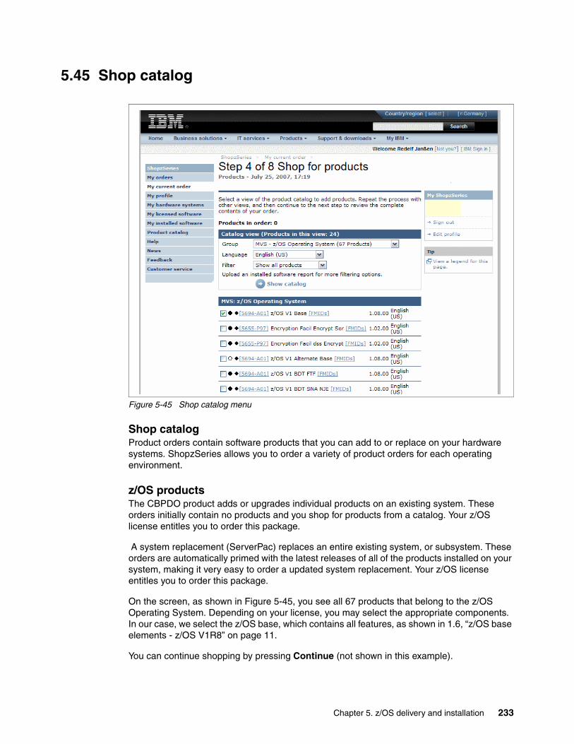
5.45 Shop catalog
Figure 5-45 Shop catalog menu
Shop catalogProduct orders contain software products that you can add to or replace on your hardware systems. ShopzSeries allows you to order a variety of product orders for each operating environment.
z/OS productsThe CBPDO product adds or upgrades individual products on an existing system. These orders initially contain no products and you shop for products from a catalog. Your z/OS license entitles you to order this package.
A system replacement (ServerPac) replaces an entire existing system, or subsystem. These orders are automatically primed with the latest releases of all of the products installed on your system, making it very easy to order a updated system replacement. Your z/OS license entitles you to order this package.
On the screen, as shown in Figure 5-45, you see all 67 products that belong to the z/OS Operating System. Depending on your license, you may select the appropriate components. In our case, we select the z/OS base, which contains all features, as shown in 1.6, “z/OS base elements - z/OS V1R8” on page 11.
You can continue shopping by pressing Continue (not shown in this example).
Chapter 5. z/OS delivery and installation 233

5.46 Specify order contents step 5 of 8
Figure 5-46 Specify order contents menu
Specify order contents step 5 of 8The process of creating an order is broken up into a series of small steps. Different categories of orders have different steps:
� Service orders
� Service subscription orders
� Automated delivery certificates
� Product orders
� Driving systems
� Customized service
� Customized products
While you are working on an order, you can navigate to other features of ShopzSeries and quickly return to your order using the My current order link in the left navigation area. However, you should save your order periodically by using the Save button on the bottom of each step. That way, if you leave ShopzSeries or your session times out, you will be able to find and continue working on your saved draft orders on the Draft orders page.
As a result of step 4, your order has been verified. In step 5, you can make changes to the contents, or keep them as they were selected.
Press Continue to proceed to step 6.
234 ABCs of z/OS System Programming Volume 1
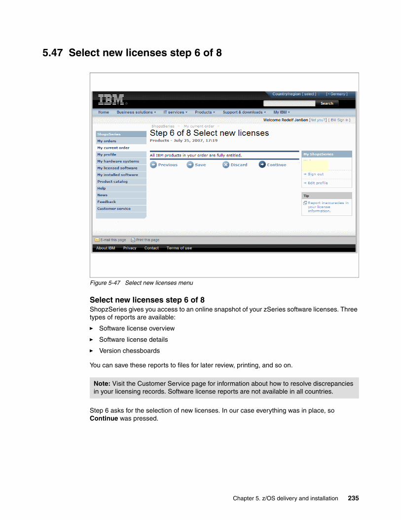
5.47 Select new licenses step 6 of 8
Figure 5-47 Select new licenses menu
Select new licenses step 6 of 8ShopzSeries gives you access to an online snapshot of your zSeries software licenses. Three types of reports are available:
� Software license overview
� Software license details
� Version chessboards
You can save these reports to files for later review, printing, and so on.
Step 6 asks for the selection of new licenses. In our case everything was in place, so Continue was pressed.
Note: Visit the Customer Service page for information about how to resolve discrepancies in your licensing records. Software license reports are not available in all countries.
Chapter 5. z/OS delivery and installation 235

5.48 Specify delivery options step 7 of 8
Figure 5-48 Specify delivery options menu
Specify delivery options step 7 of 8After you submit an order, you can review it by clicking its name in the In process section of the My orders page. (If all processing for the order has already completed, however, you can find it in the Completed section.) You can also track your order's progress. If you selected Internet delivery, you can download it from ShopzSeries.
Most ShopzSeries orders are eligible for Internet delivery. If your order is eligible, you will be able to select Internet as the preferred delivery media for your order. If you prefer the delivery via cartridge, you can enter the type of cartridge here (possible types are 3480, 3490, 3590, and 3592).
z/OS host requirements Internet Delivery requires z/OS V1R3 (5694-A01) or higher. Internet Delivery may also require an appropriate version of SMP/E, depending on the type of package and your selected download method.
For Internet Delivery of CBPDO or service using the SMP/E RECEIVE FROMNETWORK function, you need IBM SMP/E for z/OS and OS/390 V3.1 (5655-G44), including SMP/E PTF UR53608 (SMP/E level 31.12)
For Internet Delivery of ServerPac, which uses the SMP/E GIMGTPKG service routine, you need IBM SMP/E for z/OS and OS/390 V3.3 (5655-G44) or higher.
236 ABCs of z/OS System Programming Volume 1

Internet delivery also requires:
� A download file system
Your order is provided in a compressed format and is saved in a download file system. The size of this file system should be approximately twice the compressed size of your order to accommodate the order and workspace to process it.
� Firewall configuration
If your enterprise requires specific commands to allow the download of your order using FTP through a local firewall, you must identify these commands for later use in the ServerPac Dialog or RECEIVE FROMNETWORK job (RFNJOB), which manages the download of your order.
� The proper dialog level for ServerPac orders
If you are using a dialog with a Package Version less than 17.00.00, you must migrate the dialog to this level or later. To determine whether you have the correct dialog level, look for this text at the bottom of the main panel, CPPPPOLI:
This dialog supports electronic delivery.
If your dialog is not at the minimum level, follow the migration scenarios and steps described in ServerPac: Using the Installation Dialog.
SMP/ESMP/E is an element in z/OS or you can order the latest SMP/E product as a free product (5655-G44), entitled to z/OS customers. You can even download SMP/E V3.3 from the Internet, but if you do, you should also order it separately to ensure that your software profile is updated and that you are registered to receive service.
This package includes the function required for Internet delivery, and is also intended to provide the SMP/E network capabilities in situations where you do not have the required level of SMP/E installed. You should download SMP/E V3.3.
ICSFInternet Delivery also requires either ICSF (active) or SMP/E V3.4: Integrated Cryptographic Service Facility (ICSF).
ICSF is a component of base element Cryptographic Services and is used by SMP/E V3 to calculate SHA-1 hash values. These hash values are calculated by the GIMGTPKG service routine or the RECEIVE FROMNETWORK function for files within a GIMZIP package to verify the integrity of the data within the package. You must have ICSF configured and active.
In step 7, you are asked to specify your delivery medium of choice. In our case, Internet Delivery was chosen to demonstrate the process of ordering and receiving through this medium. Press Continue to proceed to the last step of the order process.
Chapter 5. z/OS delivery and installation 237

5.49 Review and submit order step 8 of 8
Figure 5-49 Review and submit order menu
Review and submit order step 8 of 8The final step of every product order is to review all of your selections from the previous steps. As you review your order, you can jump back to any step in which you want to change your choices. After you finish verifying your order, you can submit it for processing.
If the order does not include any new licenses, it is submitted directly for fulfillment. However, if you did request new licenses, then it is submitted for pricing and you will be notified when your pricing is ready.
In step 8 you can review your order information. Next, navigate to the bottom of the Web page (not shown on Figure 5-49) and press Submit to submit your z/OS order for processing by IBM.
A few days after submitting your order, you will receive an e-mail from IBM indicating the ServerPac has been produced and is ready for download.
0000001
238 ABCs of z/OS System Programming Volume 1

5.50 In process orders
Figure 5-50 In process orders menu
In process ordersOrders placed through ShopzSeries can also be tracked through delivery right from ShopzSeries. To track your orders, go to the In process section of the My orders page. The current status of each order is displayed. If there is additional tracking information for an order, the status may appear as a link which can be followed to view the additional information.
For service orders, when you review the order by clicking its name, you may also see a Manufacturing order number and a Manufacturing status, which are returned by the service manufacturing system. This information can help in the unlikely event that problems occur with your order. For example, if the service could not be shipped via the Internet, or if the service you ordered could not be found, the Manufacturing status field will inform you of the situation.
The menu as shown in Figure 5-50 displays an overview of your current orders. There can be draft orders, orders in process, or completed orders. If you have placed several orders, you can see the status of each one.
On the status field shown here, you can see that the order submitted is in the process of being manufactured.
0000001
Chapter 5. z/OS delivery and installation 239

5.51 Finished order
Figure 5-51 Finished order menu
Finished orderWhile you are working on an order, you can navigate to other features of ShopzSeries and quickly return to your order by using the My current order link in the left navigation area. However, you should save your order periodically by using the Save button on the bottom of each step. That way, if you leave ShopzSeries or your session times out, you will be able to find and continue working on your saved draft orders on the Draft orders page.
After you submit an order, you can review it by clicking its name in the In process section of the My orders page. (If all processing for the order has already completed, you can find it in the Completed section.)
Orders placed through ShopzSeries can also be tracked through delivery right from ShopzSeries. To track your orders, go to the In process section of the My orders page. The current status of each order is displayed. If there is additional tracking information for an order, the status may appear as a link which can be followed to view the additional information.
For service orders, when you review the order by clicking its name, you may also see a Manufacturing order number and a Manufacturing status which are returned by the service manufacturing system. This information can help in the unlikely event that problems occur with your order. For example, if the service could not be shipped via the Internet, or if the service you ordered could not be found, the Manufacturing status field will inform you of the situation.
0000001
240 ABCs of z/OS System Programming Volume 1

5.52 Download order information
Figure 5-52 Download order information menu
Download order informationWhen your order is ready to be downloaded, you will receive an e-mail notification with a link that will take you right to your order for immediate downloading. You can also download your orders from the In process section of the My orders page by clicking the Download link for the order you want to download.
After you reach the Download page for your order, click the links to view or download the various components of your order.
Chapter 5. z/OS delivery and installation 241

5.53 Download instructions
Figure 5-53 Download instructions menu
Downloading z/OS order directly to a hostFor ServerPac orders, you will use the ServerPac Dialog to generate the RECEIVE job, which will invoke the SMP/E GIMGTPKG service routine to download your order from the IBM server to the download file system on your host. You will need to provide the information found on the download page to the dialog for the RECEIVE job to be generated. For CBPDO orders, you will use the provided customized JCL job (RFNJOB). This job invokes the SMP/E RECEIVE FROMNETWORK command to download your order using TCP/IP FTP from an IBM server to your SMPNTS file system, and then performs the SMP/E RECEIVE for the order. For most service orders, you can also choose to download the order directly to your host by using a sample batch FTP JCL job that is supplied with your order.
CustomPac logon informationCustomized offerings, or CustomPacs, are IBM Global Services offerings that require special contracts, as follows:
� ProductPac - Delivers products which are built according to the SMP/E CSI which you provide.
� FunctionPac -Delivers a group of z/OS-related products in a new SMP/E zone as a snap-on.
� SystemPac -A system migration package that helps you plan and install IBM and ISV products and subsystems in a single package with up-front customization and subsequent maintenance to maintain your system over time.
242 ABCs of z/OS System Programming Volume 1

Chapter 6. z/OS maintenance concepts
Software management is a key discipline that can help you to achieve high availability and continuous operation in your z/OS environment. It can also assist in lowering the cost of installing, testing, operating, and maintaining your systems.
This chapter discusses the following topics:
� Aspects of software management
� Software management tasks
� z/OS software management cycle
� How current should your software be
6
© Copyright IBM Corp. 2008. All rights reserved. 243

6.1 Aspects of software management
Figure 6-1 Aspects of software management
Aspects of software managementThere are different aspects of software management. Although this book is focused on the z/OS platform, many of the software management concepts presented here are generally valid for other platforms, as well.
Why should you manage softwareManaging software is important because it concerns which techniques you use to implement changes in your operating system software environment. And in a typical IT environment, it is likely that there will be a continuous need for changes based on, for example:
� Implementation of new functions� Support for new hardware� Software maintenance� Implementation of new software releases
How current should your software beThis aspect of software management involves making decisions concerning how up-to-date you need your software to be. Refer to 6.4, “How current should your software be” on page 249 for more discussion about this topic.
Why should you manage software?
How current should you be with your software?
An approach for keeping your environment current
Installation strategy
Implementation strategy
Concurrent maintenance
244 ABCs of z/OS System Programming Volume 1

An approach for keeping your environment currentThere are different approaches and techniques for keeping your z/OS environment current. Although you could keep your system as it was when installed and only update it when errors occur, this is not a recommended approach.
Instead, you can use common tools such as these to keep your environment current:
� ServerPac and SystemPac� CBPDO� ServicePac
The tools are described more in detail in Chapter 5, “z/OS delivery and installation” on page 187.
Installation strategyPrior to making a change, you must decide which upgrade method to use:
� System replacement, or
� System upgrade
The method you choose also depends on different considerations:
� Complexity of your environment
� Current service level
� Maturity of your system management processes (that is, change management and problem management)
� Number of products (z/OS and vendor products)
Implementation strategyAlthough installation is one important task, implementation is another. For example, for effective implementation you must decide where to put data sets and how to handle IBM and vendor products, or how to prepare your system for the following cloning processes.
Concurrent maintenanceUnder normal circumstances, you perform maintenance non-concurrently. This means you install fixes and test them, then clone the environment and bring the actual version of the operating system or other software products into production.
However, there could be situations in which it is necessary to install fixes concurrently and activate the new modules via an MVS console command. Be aware that this method should be used only in critical situations.
Chapter 6. z/OS maintenance concepts 245

6.2 Software management tasks
Figure 6-2 Cycle of software management tasks
Software management tasksA “maintenance philosophy” involves numerous software management tasks, and it is an ongoing, cyclical process as shown in Figure 6-2. For example, after finishing the implementation of a z/OS release, you might be asked to evaluate new functions that require PTFs.
Environment designThe environment design phase is the starting point for the cycle that follows. During this phase you decide how to design and set up your environment for system maintenance. This phase includes the following tasks:
� Definition of installation-wide naming standards
� Logical design of the environment
� Use of shared system residences (SYSRES)
� Design of the catalog environment
� Physical design of the environment (for example, I/O configuration)
� Cloning techniques
Environment Design Installation
Decision
Installation Plan
InstallationTesting
Implementation
246 ABCs of z/OS System Programming Volume 1

Installation decisionAn installation decision is primarily a business decision, rather than a technical decision. It may involve, for example, the need for new function implementation, or the withdrawal of a z/OS release from service.
Installation planAfter the installation decision is made, you are responsible for the planning phase. Planning is important, because the resources you need for the subsequent installation, testing, and implementation will cost your organization money. These costs may belong to different areas:
� Hardware (CPU resources, DASD space)
� Software (for example, new licenses)
� Project support personnel
Planning requires good project management. Therefore, you will need to develop a plan that includes the following items:
� Key activities
� Responsibilities
� Timetable
InstallationIn this case, installation is the process of bringing a new z/OS release to your DASD environment. As previously mentioned, you will normally perform an installation by using the ServerPac dialog technique or by doing it via CBPDO. We describe the ServerPac installation technique in Chapter 5, “z/OS delivery and installation” on page 187.
TestingIt is important to test new software components prior to introducing them into your production. environment. Testing is necessary for quality assurance. There are different test categories for verification and validation of a new environment. These categories can be:
� Unit tests� Integration tests� Function tests� System tests� Acceptance tests� Regression tests� Capacity tests� Stress tests
ImplementationAfter doing the basic installation (for example, by using ServerPac), you still have to perform many other implementation activities on your z/OS environment before you can propagate it to a test or production system. These activities, using the ServerPac custom dialog, are described in 5.10, “Installing the CustomPac dialogs” on page 198,.
Chapter 6. z/OS maintenance concepts 247

6.3 The z/OS software management cycle
Figure 6-3 The software management cycle
The z/OS software management cycleFigure 6-3 shows the software management cycle, which illustrates how software management works in a z/OS environment. From a software management perspective, it involves two major factors:
� The last software management activity you performed
� The software management strategy of your enterprise that is the base for your future activities
New version /system
Correctiveservice
Preventiveservice
New products
z/OSz/OS
248 ABCs of z/OS System Programming Volume 1

6.4 How current should your software be
Figure 6-4 Current level of software
How current should your software beOne challenge that is common to all enterprises, independent of IT infrastructure, is the risk raised by change. You may encounter a philosophy such as “never change a running system.” However, when it comes to software maintenance, an IT organization must consider the following questions:
� How current should our z/OS environment be?
� What are our guidelines and procedures for z/OS maintenance levels?
� Should we install preventive maintenance, or fix problems as they occur?
What is the risk of not changing softwareThere are a number of issues that might occur if you do not keep your z/OS software stack current; for example:
� You may not be able to implement new software functions.
� You cannot easily implement new hardware.
� New releases of software may not interact with other software due to incompatibilities or synchronization problems.
� Problems that are already resolved by IBM may be rediscovered in your environment and may result in unnecessary outages.
What is the risk of not changing software?
What is the risk of changing software?
What is the minimum risk point?
Chapter 6. z/OS maintenance concepts 249
What is the risk of changing softwareThe closer you come to the most current level of your software, the greater is the risk of experiencing a failure or outage.
What is the minimum risk pointThe point of minimum risk for installing new fixes to an already installed operating system release or even to a new release might be somewhere between being too far behind and too current.
Defining a point of minimum risk can be a challenge, so it may be helpful to first determine the requirements for your enterprise, and then compare these requirements to the level of software release that you are able to install and implement.
250 ABCs of z/OS System Programming Volume 1

Related publications
The publications listed in this section are considered particularly suitable for a more detailed discussion of the topics covered in this IBM Redbook.
IBM Redbooks
For information about ordering these publications, see “How to get IBM Redbooks” on page 252. Note that some of the documents referenced here may be available in softcopy only.
� ABCs of z/OS System Programming Volume 2, SG24-6982
� ABCs of z/OS System Programming Volume 7, SG24-6987
� ABCs of z/OS System Programming Volume 10, SG24-6990
Other publications
These publications are also relevant as further information sources:
� z/OS Security Server RACF System Programmer's Guide, SA22-7681
� z/OS TSO/E Customization, SA22-7783
� z/OS MVS Initialization and Tuning Reference, SA22-7592
� z/OS TSO/E Primer, SA22-7787
� z/OS TSO/E User's Guide, SA22-7794
� z/OS TSO/E Command Reference, SA22-7782
� z/OS ISPF Dialog Developer's Guide, SC34-4821
� z/OS ISPF Software Configuration Library Manager Reference, SC34-4818
� z/OS MVS JCL User’s Guide, SA22-7598
� z/OS MVS JCL Reference, SA22-7597
� z/OS Planning for Installation, GA22-7504
� IBM ServerPac Using the Installation Dialog, SA22-7815
Online resources
These Web sites are also relevant as further information sources:
� You can reach the start page by entering the following link:
https://www14.software.ibm.com/webapp/ShopzSeries/ShopzSeries.jsp
© Copyright IBM Corp. 2008. All rights reserved. 251

How to get IBM Redbooks
You can search for, view, or download IBM Redbooks, IBM Redpapers, Technotes, draft publications and Additional materials, as well as order hardcopy Redbooks, at this Web site:
ibm.com/redbooks
Help from IBM
IBM Support and downloads
ibm.com/support
IBM Global Services
ibm.com/services
252 ABCs of z/OS System Programming Volume 1

(0.5” spine)0.475”<
->0.873”
250 <->
459 pages
ABCs of z/OS System Program
ming Volum
e 1
ABCs of z/OS System Program
ming
Volume 1
ABCs of z/OS System Program
ming
Volume 1
ABCs of z/OS System Program
ming Volum
e 1

ABCs of z/OS System Program
ming
Volume 1
ABCs of z/OS System Program
ming
Volume 1

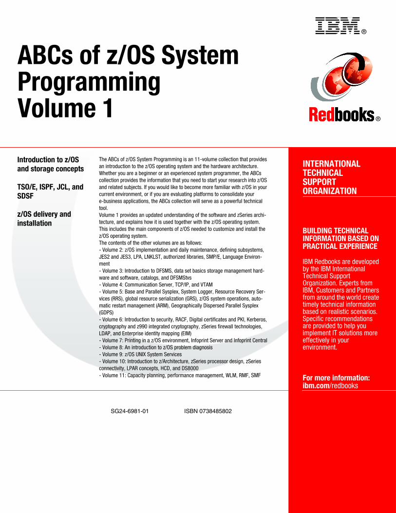
®
SG24-6981-01 ISBN 0738485802
INTERNATIONAL TECHNICALSUPPORTORGANIZATION
BUILDING TECHNICAL INFORMATION BASED ON PRACTICAL EXPERIENCE
IBM Redbooks are developed by the IBM International Technical Support Organization. Experts from IBM, Customers and Partners from around the world create timely technical information based on realistic scenarios. Specific recommendations are provided to help you implement IT solutions more effectively in your environment.
For more information:ibm.com/redbooks
®
ABCs of z/OS SystemProgrammingVolume 1
Introduction to z/OS and storage concepts
TSO/E, ISPF, JCL, and SDSF
z/OS delivery and installation
The ABCs of z/OS System Programming is an 11-volume collection that provides an introduction to the z/OS operating system and the hardware architecture. Whether you are a beginner or an experienced system programmer, the ABCs collection provides the information that you need to start your research into z/OS and related subjects. If you would like to become more familiar with z/OS in your current environment, or if you are evaluating platforms to consolidate your e-business applications, the ABCs collection will serve as a powerful technical tool. Volume 1 provides an updated understanding of the software and zSeries archi-tecture, and explains how it is used together with the z/OS operating system. This includes the main components of z/OS needed to customize and install the z/OS operating system. The contents of the other volumes are as follows:- Volume 2: z/OS implementation and daily maintenance, defining subsystems, JES2 and JES3, LPA, LNKLST, authorized libraries, SMP/E, Language Environ-ment- Volume 3: Introduction to DFSMS, data set basics storage management hard-ware and software, catalogs, and DFSMStvs- Volume 4: Communication Server, TCP/IP, and VTAM- Volume 5: Base and Parallel Sysplex, System Logger, Resource Recovery Ser-vices (RRS), global resource serialization (GRS), z/OS system operations, auto-matic restart management (ARM), Geographically Dispersed Parallel Sysplex (GDPS)- Volume 6: Introduction to security, RACF, Digital certificates and PKI, Kerberos, cryptography and z990 integrated cryptography, zSeries firewall technologies, LDAP, and Enterprise identity mapping (EIM)- Volume 7: Printing in a z/OS environment, Infoprint Server and Infoprint Central- Volume 8: An introduction to z/OS problem diagnosis- Volume 9: z/OS UNIX System Services- Volume 10: Introduction to z/Architecture, zSeries processor design, zSeries connectivity, LPAR concepts, HCD, and DS8000- Volume 11: Capacity planning, performance management, WLM, RMF, SMF
Back cover