abc manufacturing - m&e engrg
TRANSCRIPT

HS Inspection Pte Ltd Blk 3021, Ubi Avenue 2 #02-161 S(408897) Tel: (65)-68420900 Fax: (65)-67417411
email: [email protected] Co. Reg. No: 199408887D
1
Infrared Thermographic Inspection for ABC Manufacturing (S) Pte Ltd
on Jan 04, 2012
Conducted By: Mr. Amos Chua Certified Level 2 Thermographer
ABC
Manufacturing
Certified Thermographer

HS Inspection Pte Ltd Blk 3021, Ubi Avenue 2 #02-161 S(408897) Tel: (65)-68420900 Fax: (65)-67417411
email: [email protected] Co. Reg. No: 199408887D
2
FOREWORD
This report provides complete documentation of the exceptions (abnormally warm or cool equipment) found during the infrared inspection of your equipment. It uses a variety of data and ratings to help prioritize your repairs and give you the greatest return from your maintenance efforts. This inspection and report have been performed and prepared by Amos Chua, Certified Infrared Thermographer. To earn this certification, the candidate must pass the Level I and Level II examinations administered by the Infraspection Institute and Academy of Infrared Thermography. This report fully meets the requirement of the Infraspection Institute's "Guidelines for Infrared Inspection of Electrical and Mechanical Systems". It also references, incorporates and exceeds all other published guidelines and standards pertaining to the infrared inspection of electrical and mechanical systems.
HOW INFRARED THERMOGRAPHY WORKS
Infrared images are sophisticated electronic cameras that "see" the heat radiated from your equipment. In black-and-white thermograms (pictures of heat), white is hot and black is cold unless stated otherwise. If the thermograms are in color, usually the white and red areas are hotter and black and blue areas are colder. Infrared Thermographer uses these special cameras to locate and measure the temperature of exceptions. Overheating can cause premature deterioration and costly unplanned failure of your equipment. With our advance notice, you can pro-actively service this equipment before it creates costly problems.

HS Inspection Pte Ltd Blk 3021, Ubi Avenue 2 #02-161 S(408897) Tel: (65)-68420900 Fax: (65)-67417411
email: [email protected] Co. Reg. No: 199408887D
3
REPAIR PRIORITY RATINGS
Maintenance personnel need to prioritize their repair efforts. So we provide you with a Repair Priority Rating for each exception identified in this report. This Repair Priority Rating comes from subjective and /or objective ratings. Subjective Ratings are determined by your qualified assistant or representative who considers how important the potential problem is to the safe and profitable operation of the system. When a thermographer performs a qualitative infrared inspection (takes no temperatures), the only rating is the Subjective Repair Priority Rating. Temperature Severity Ratings are objective and based on temperatures taken by the thermographer. Exception and other reference temperatures are compared to industry standards and guidelines to produce an objective Temperature Severity Rating. When the infrared inspection is quantitative, we have used the following temperature criteria to assign Temperature Severity Ratings to the exceptions: Experienced Based Standard:
1) >50 C Deg and above: corrective measures required IMMEDIATELY
2) 30 - 50 C Deg: corrective measures required ASAP
3) 15 - 29 C Deg: corrective measures required as scheduling permits
4) < 15 C Deg: corrective measures should be taken at the next maintenance period When the thermographer provides a quantitative infrared inspection (takes temperatures), the Subjective and Temperature Severity Ratings are averaged to give you a recommended Average Repair Priority Rating. While these repair ratings will help you prioritize your maintenance efforts, you must understand that the failure curves of many electrical and mechanical components are not linear and predictable. Therefore, you should investigate and repair all reported exceptions as soon as possible. And once repaired, each should be re-inspected i.e. post scan to assure that its temperature is normal and that the potential problem has been corrected. Note that for every problem always inspect for physical damage to determine repair or replacement of the particular component identified. There are no rules for the assessment of excess temperatures, which are measured on indirectly overheated surfaces. Indirect overheating can be caused by hidden faults, e.g. cracks inside a breaker where the temperature is measured from the outside. Experience shows that oil insulated transformers and breakers with internal faults where an approximately temperature increase of 10% has been measured on the surface are considerably hotter inside. Very often the faulty parts are severely burnt.
ELECTRO-MECHANICAL PREVENTATIVE MAINTENANCE SURVEYS SHOULD BE USED AT LEAST TWICE A YEAR

HS Inspection Pte Ltd Blk 3021, Ubi Avenue 2 #02-161 S(408897) Tel: (65)-68420900 Fax: (65)-67417411
email: [email protected] Co. Reg. No: 199408887D
4
INSPECTION SUMMARY
1. The inspection was conducted and completed on Jan 04, 2013. A total of 60 items was inspected and 03 exceptions/faults detected.
2. A breakdown of the no. of exceptions and repair priority found are as follow:
Repair Priority Number of Exception(s)
Priority 1 1
Priority 2 1
Priority 3 1
Priority 4 0
Total No. of Exceptions 3 3. Any potential problem was listed according to its Repair Priority Ratings. The ratings are as follow: Priority 1 : corrective measures required IMMEDIATELY Priority 2 : corrective measures required ASAP Priority 3 : corrective measures required as scheduling permits Priority 4 : corrective measures should be taken at the next maintenance period 4. Besides the exception images, we also include some reference images of the equipment that we have
inspected.

HS Inspection Pte Ltd Blk 3021, Ubi Avenue 2 #02-161 S(408897) Tel: (65)-68420900 Fax: (65)-67417411
email: [email protected] Co. Reg. No: 199408887D
5
EXCEPTIONS LIST
1. The list of the equipment that was inspected is tabulated in the following pages. Each item that has been identified as a potential problem is marked in bold, its exception number and Repair Priority Rating are also noted in the right columns in accordance to its respective repair priority colour coding.
2. The following abbreviations and symbols are used in the tables below:
Abbreviations/ Symbols Meaning
NOL Not On Load or very low load less than 5% of maximum rating
NOP Not Operating
NA Not Applicable E0X Exception No. E0X
IL Interlock. Either the panel breaker is interlock or the room leading to the panel was locked at the time of the inspection
RXX Electrically related Reference Thermal Image # XX UM Under Maintenance
P
No thermal anomaly but the inspection is partial and limited by the line-of-sight of the Infrared camera. The outgoing busbar section cannot be seen even from the front of the switchboard. No access to the outgoing busbar section while the circuit is LIVE.
S
The equipment panel was interlock and it had to be stopped for a short while so that the panel could be opened for inspection. The residue heat of the equipment was sufficient for us to make a fair assessment and no thermal anomaly recorded.
No thermal anomaly No thermal anomaly but inspection restricted to surface scan only
* Equipment was inspected but load was less than 30% of maximum rating hence the scan result may not be reliable
** Equipment was at very very low load hence the scan result may not be reliable

HS Inspection Pte Ltd Blk 3021, Ubi Avenue 2 #02-161 S(408897) Tel: (65)-68420900 Fax: (65)-67417411
email: [email protected] Co. Reg. No: 199408887D
6
Inspection list for ABC Manufacturing (S) Pte Ltd on Jan 04, 2012
Item Floor Location/ Main Board Equipment Ref
Image # Exception Repair Priority
1. 1st Floor LV Switch Room/ MSB
Cubicle 1 • 600A Q1-2 (Machine A) • 800A Q1-3 Spare
R01
NOP
NA 2. Cubicle 2
• 600A Q1-5 (Machine B) • 400A Q1-6
NOP
NA 3. Cubicle 3
• 800A Q1-7 Spare • 300A Q1-4 Spare
NOP NOP
NA NA
4. Cubicle 4 • Q1-8 ACB, 1600A
Mitsubishi ACB
5. Cubicle 5 • 600A (Machine C) • 400A Spare • 400A Heater • 400A Press Machine • 200A Workshop • 200A Pond Water
Pump/Perimeter Light • 200A Compressor No. 3
(Kaeser) • 200A DB Comp No. 5
NOP *
*
*
NA * *
*
* 6. Cubicle 6
• From 22KV/433V 1000KVA, T/F No. 1 ACB, Mitsubishi 1600A
R02
7. Cubicle 7 • Isolator Coupler • Feeder 1 Relay • Feeder 2 Relay
NOP ** **
NA ** **
8. Cubicle 4 • From 22KV/433V 1000KVA,
T/F No. 2 ACB
9. Cubicle 5 • 400A DB Office • 600A Machine D • 400A Compressors 3 • 200A DB Aircon • 125A 2nd Storey Office DB
(Supply from DB-OFF) • 200A Rotary Control Panel • 200A Supply to Line 1
Control Panel • 60A Canteen Aircon/Power
Points
*
*
*
*
10. LT Switch Room / EMSB
Cubicle 1 • QNM/ QEM I From MSB • QNM/QEM II From Genset
*
NOP
* NA

HS Inspection Pte Ltd Blk 3021, Ubi Avenue 2 #02-161 S(408897) Tel: (65)-68420900 Fax: (65)-67417411
email: [email protected] Co. Reg. No: 199408887D
7
Item Floor Location/ Main Board Equipment Ref
Image # Exception Repair Priority
11. 1st Floor LT Switch Room / EMSB
Cubicle 2 • QE Main Incoming, 1600A
Mitsubishi ACB
**
**
12. Cubicle 3 • QE-1 300A Busduct T1 • QE-8 200A LSB R-3 • QE-14 100A Spare
** **
NOP
** ** NA
13. Cubicle 4 • QE-1 Earth Fault Relay • QE-2 Earth Fault Relay
** **
** **
14. Cubicle 6 • QE-6 500A LSB R-1 • QE-10 100A SB 2 • QE-5 63A SB 3 • QE-11 63A MCC R-1
** ** ** **
** ** ** **
15. Cubicle 7 • QE-6 Earth Fault Relay • QE-7 Earth Fault Relay
** **
** **
16. Cubicle 8 • QE-7 500A LSB R-2 • QE-15 100A Spare • QE-12 63A DB -1E • QE-13 63A SB 4
**
NOP ** **
** NA ** **
17. Transformer Room T/F 1, 22KV/433V, 1000KVA, Meiden Transformer Oil Cooled (mineral)
18. T/F 2, 22KV/433V, 2500KVA, Meiden Transformer Oil Cooled (mineral)
19. Room Beside Production Office/ MCP-4
Cubicle 1 • Cable Termination
20. Cubicle 2 • 400A Main Incoming • 63A AC Humidifier • 100A Line 2 A/C
NOP
NA 21. Cubicle 3
• MCBs • 30A Press Machine • 60A DB1 • 60A Office
22. Cubicle 4 • MCP 6 • “Production Office” MCB,
outgoing phase
E01
3
23. Production Office DB-4 * * 24. AHU 1 Room AHU Control Panel (1-3) 25. AHU 3 Room AHU Control Panel (1-7) 26. Line 1 DB 1 R03 * * 27. DB 2 * * 28. DB 3 * *
HS Inspection Pte Ltd Blk 3021, Ubi Avenue 2 #02-161 S(408897) Tel: (65)-68420900 Fax: (65)-67417411
email: [email protected] Co. Reg. No: 199408887D
8
Item Floor Location/ Main Board Equipment Ref
Image # Exception Repair Priority
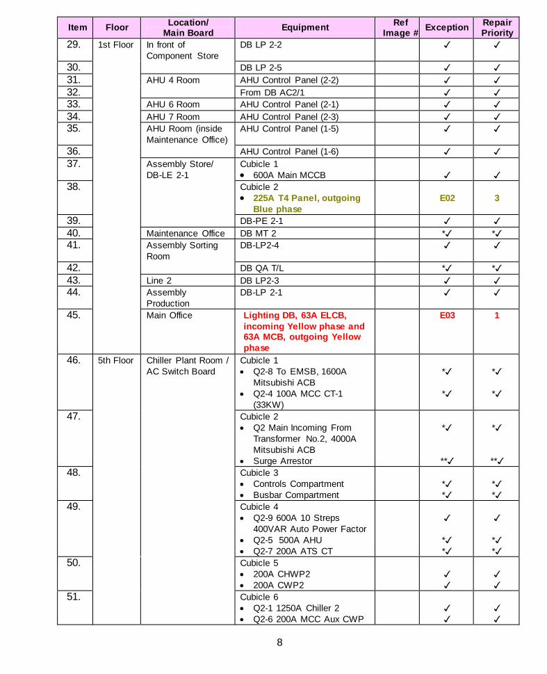
29. 1st Floor In front of Component Store
DB LP 2-2
30. DB LP 2-5 31. AHU 4 Room AHU Control Panel (2-2) 32. From DB AC2/1 33. AHU 6 Room AHU Control Panel (2-1) 34. AHU 7 Room AHU Control Panel (2-3) 35. AHU Room (inside
Maintenance Office) AHU Control Panel (1-5)
36. AHU Control Panel (1-6) 37. Assembly Store/
DB-LE 2-1 Cubicle 1 • 600A Main MCCB
38. Cubicle 2 • 225A T4 Panel, outgoing
Blue phase
E02
3
39. DB-PE 2-1 40. Maintenance Office DB MT 2 * * 41. Assembly Sorting
Room DB-LP2-4
42. DB QA T/L * * 43. Line 2 DB LP2-3 44. Assembly
Production DB-LP 2-1
45. Main Office Lighting DB, 63A ELCB, incoming Yellow phase and 63A MCB, outgoing Yellow phase
E03 1
46. 5th Floor Chiller Plant Room / AC Switch Board
Cubicle 1 • Q2-8 To EMSB, 1600A
Mitsubishi ACB • Q2-4 100A MCC CT-1
(33KW)
*
*
*
*
47. Cubicle 2 • Q2 Main Incoming From
Transformer No.2, 4000A Mitsubishi ACB
• Surge Arrestor
*
**
*
** 48. Cubicle 3
• Controls Compartment • Busbar Compartment
* *
* *
49. Cubicle 4 • Q2-9 600A 10 Streps
400VAR Auto Power Factor • Q2-5 500A AHU • Q2-7 200A ATS CT
* *
* *
50. Cubicle 5 • 200A CHWP2 • 200A CWP2
51. Cubicle 6 • Q2-1 1250A Chiller 2 • Q2-6 200A MCC Aux CWP

HS Inspection Pte Ltd Blk 3021, Ubi Avenue 2 #02-161 S(408897) Tel: (65)-68420900 Fax: (65)-67417411
email: [email protected] Co. Reg. No: 199408887D
9
Item Floor Location/ Main Board Equipment Ref
Image # Exception Repair Priority
52. 5th Floor Chiller Plant Room / AC Switch Board
Cubicle 7 • QC Coupler, 4000A
Mitsubishi ACB • Q1-8 63A AHU 5 (15KW) • Q1-10 150A AHU 6
NOP
*
NOL
NA
* NA
53. Cubicle 8 • Q1 Main Incoming From
Transformer No.1, 4000A Mitsubishi ACB
54. Cubicle 9 • Controls Compartment • Busbar Compartment
**
**
55. Cubicle 10 • Q1-13 600A 10 Streps
400VAR Auto Power Factor • Q1-9 500A AHU • Q1-7 150A MCC CT2
(55.5KW)
*
*
*
*
56. Cubicle 11 • Q1-1 1250A Chiller 1 • Q1-12 200A Spare
NOP
NA 57. Cubicle 11
• Q1-2 1250A Chiller 2 • Q1-13 200A Spare
NOP
NA 58. Cubicle 12
• Q1-3 630A Chiller 3 • Q1-14 200A Spare
NOP
NA 59. Cubicle 13
• CWP3 (150A) • CWP1 (200A)
60. Cubicle 14 • CHWP3 (150A) • CHWP1 (200A)

HS Inspection Pte Ltd Blk 3021, Ubi Avenue 2 #02-161 S(408897) Tel: (65)-68420900 Fax: (65)-67417411
email: [email protected] Co. Reg. No: 199408887D
10
DATALOG 1. Mr Amos Chua
(Certified Level II Thermographer)
2. Mr Kong Choy (Assistant-Mounting and dismounting of panels)
Client's Representatives: (Name and Title) 1. Mr Jonathan Tay 2. Mr Chua EXCEPTION STANDARDS Temperature in Units of: Centigrade Exception Criteria: (x) Experienced Based ( ) N.E.T.A. Standards (ATS-1991) ( ) Military Standards (MIL-STD-2194) ( ) ERICS

HS Inspection Pte Ltd Blk 3021, Ubi Avenue 2 #02-161 S(408897) Tel: (65)-68420900 Fax: (65)-67417411
email: [email protected] Co. Reg. No: 199408887D
11
THE MYTH OF TIGHTENING ELECTRICAL CONNECTIONS (written by Ron Newport) With conventional preventive maintenance, a number of procedures are carried out. They are visual inspection, cleaning equipment, tightening connections, over-current device testing, resistance testing, insulation testing etc. All of these procedures and others have their place except one. That is the systematic tightening of electrical connections. Case Study This myth first became evident to thermographers in USA and Europe more than 2 decades ago. An infrared electrical inspection was carried out at a pulp and paper mill prior to shutdown. Afterwards another inspection was requested in order to evaluate the repairs as well as inspect newly installed equipment. What was found was disconcerting to both thermographer and electrical supervisor. They found that 40% of the faults first discovered were still problems. Some of the faults were not as bad and some were worse. This percentage over the years has turned out to be quite consistent worldwide, regardless of what area of the electrical industry the inspection was made. The reason for this usually two-fold. One is that the chosen method of repair was incorrect for the type of problem. And two, the problem was not identified or diagnosed properly and maintenance carried out on the wrong component. In this situation, of the 40% of anomalies still in existence most were contact problems. Notice we did not say loose connections! Typically, when a connection is identified as a thermal anomaly, it is assumed the connection is loose and hence the chosen repair is to tighten the bolt or screw. Since the majority of faults found in any infrared inspection is connections and in many cases loose ones, this seems like a proper repair procedure. It was found that many of the connections related faults had been repaired properly. Looking into the repair records it was found that the connections, which were disassembled, cleaned and reassembled, had a 90% success rate. The ones, which were just tightened, had only approximately a 20% success rate. The reason for this is the loose bolt and connection surfaces had time to become dirty and oxidize. So when they were tightened it did not make a good connection and the fault remained. In some cases the problem was worse. It is important to understand that just because the connection is identified, as a thermal anomaly does not mean it is loose. It could be an oxidized or dirty connection, there may be a problem with the threads on the bolt, or the connection could be over tightened, or the crimping maybe no good. The only way to know for sure is to de-energize the component, disassemble it and look at it. Then and only then will we be able to do a proper diagnosis and repair procedure be established. Based on the information received from many thermographers performing inspections on millions of components in every type of industry, the general consensus was that the main culprit contributing to repeated connection problems is the routine tightening of the bolt or screw connections. The basic purpose of a bolt in an electrical system is to bring two metal surfaces together and hold them in position with the least amount of resistance to the flow of current as possible. Joint performance is a function of the clamping force applied by the fastener. Clamping force is developed by stretching the bolt an appropriate amount by tightening the nut. Because the bolt continually tries to return to its original condition, it pulls and holds the joint together. It is important when assembling bolted connections that a torque wrench is used and appropriate torque values as received from manufacturers, codes or standards be applied.

HS Inspection Pte Ltd Blk 3021, Ubi Avenue 2 #02-161 S(408897) Tel: (65)-68420900 Fax: (65)-67417411
email: [email protected] Co. Reg. No: 199408887D
12
It has been noted that bolts tightened with a torque wrench can vary 30% on the same assembly. Joints can be under tightened but typically they become over tightened after years of routine tightening (typically without a torque wrench!) The joint can become over compressed to the point of bending the metal faces, creating a poor connection, see Figure 1. As well, a bolt can become over-stretched and the joint will not attain the proper compression and will create a thermal anomaly just like a loose connection.
PROPER TORQUE OVER - TIGHTENED Some excerpts follow summarizes the general feeling towards just doing “blind” preventative maintenance: “A connection that needs periodic retightening is a connection with something basically wrong. Better advice is to check for signs of loosening or overheating. If such signs are found, the answer is to discover what’s causing them and correct it. Retightening over and over can aggravate the problem.” Jack Wells, Chairman of National Fire Protection Assoc’n “After any terminal is tightened to its prescribed torque setting, the terminal should not be retightened to that same value at a later date. Electrical connections properly made and torque at the time of installation does not require periodic retightening. Once set, a terminal should be left alone unless and until any indication of malfunction is detected..... such as overheating revealed by a thermographic inspection of their terminals” J.F.McParland, Electrical Constr. and Maintenance. These authorities as well as thermographers world-wide have found that not only is periodic retightening of terminations unnecessary but it may actually damage the connections or equipment it is attached to.

HS Inspection Pte Ltd Blk 3021, Ubi Avenue 2 #02-161 S(408897) Tel: (65)-68420900 Fax: (65)-67417411
email: [email protected] Co. Reg. No: 199408887D
E01
Quantitative Report of Infrared Survey
Client: ABC Manufacturing (S) Pte Ltd Exception: E01 Date/ Time: 04/01/2012 / 2:00:24 PM
IDENTIFICATION
Location: 1st Floor, Room Beside Production Office
Equipment: MCP-4, Cubicle 4, “Production Office” MCB, outgoing phase
Ambient: 29°C Imager: P60 PAL
EXCEPTION DESCRIPTION
:max 77.7
16.0
84.0 °C
20
40
60
80
Heat built-up detected on the MCB at max. temperature of 77.7 °C . Likely poor contact. Load condition: NA. Subjective Priority Rating: 3
REMARKS Suggest remove, clean, inspect, replace the MCB, cut the damage section of the cable, re-crimp the cable lug and retighten the termination. Please do not just tighten over existing termination (refer attached article on “The myth of tightening electrical connections”). Rectification Action: Rectification By / Date

HS Inspection Pte Ltd Blk 3021, Ubi Avenue 2 #02-161 S(408897) Tel: (65)-68420900 Fax: (65)-67417411
email: [email protected] Co. Reg. No: 199408887D
E02
Quantitative Report of Infrared Survey
Client: ABC Manufacturing (S) Pte Ltd Exception: E02 Date/ Time: 04/01/2012 / 4:46:36 PM
IDENTIFICATION
Location: 1st Floor, Assembly Store
Equipment: DB-LE 2-1, Cubicle 2, 225A T4 Panel, outgoing Blue phase
Ambient: 31°C Imager: P60 PAL
EXCEPTION DESCRIPTION
:max 90.3
17.0
93.0 °C
20
40
60
80
Heat built-up detected on the outgoing Blue phase from the MCCB at max. temperature of 90.3 °C . Likely poor contact. Load condition: ~45A per phase. Subjective Priority Rating: 2
REMARKS Suggest remove, clean, inspect the MCCB, if required replace the MCCB, cut the damage section of the cable, re-crimp the cable lug and retighten the termination asqp. Please do not just tighten over existing termination (refer attached article on “The myth of tightening electrical connections”). Rectification Action:
Rectification By / Date

HS Inspection Pte Ltd Blk 3021, Ubi Avenue 2 #02-161 S(408897) Tel: (65)-68420900 Fax: (65)-67417411
email: [email protected] Co. Reg. No: 199408887D
E03
Quantitative Report of Infrared Survey
Client: ABC Manufacturing (S) Pte Ltd Exception: E03 Date/ Time: 04/01/2012 / 3:51:41 PM IDENTIFICATION
Location: 1st Floor, Main Office
Equipment: Lighting DB, 63A ELCB, incoming Yellow phase and 63A MCB, outgoing Yellow phase
Ambient: 26°C Imager: P60 PAL
EXCEPTION DESCRIPTION
:max 120.5
10.0
125.0 °C
20
40
60
80
100
120
Heat built-up detected on the MCB at max. temperature of 120.5 °C. Likely poor contact. Load condition: ~45A per phase. Subjective Priority Rating: 1
REMARKS Suggest remove, clean, inspect, replace the MCB, ELCB and also replace the overheated cables to ELCB and from MCB and then retighten the termination immediately. Please do not just tighten over existing termination (refer attached article on “The myth of tightening electrical connections”). Rectification Action:
Rectification By / Date

HS Inspection Pte Ltd Blk 3021, Ubi Avenue 2 #02-161 S(408897) Tel: (65)-68420900 Fax: (65)-67417411
email: [email protected] Co. Reg. No: 199408887D
R01
Reference Thermal Image: R01 Client: ABC Manufacturing (S) Pte Ltd Date: 04/01/2012 Location: 1st Floor, LV Switch Room Time: 10:33:31 AM
Equipment: MSB, Cubicle 1, 600A Q1-2 (Machine A) Ambient: 30.0°C
21.0
65.0 °C
30
40
50
60
FLIR Systems
Loading: ~200A per phase
Remarks: No thermal anomaly.

HS Inspection Pte Ltd Blk 3021, Ubi Avenue 2 #02-161 S(408897) Tel: (65)-68420900 Fax: (65)-67417411
email: [email protected] Co. Reg. No: 199408887D
R02
Reference Thermal Image: R02
Client: ABC Manufacturing (S) Pte Ltd Date: 04/01/2012
Location: 1st Floor, LV Switch Room Time: 9:59:03 AM
Equipment: MSB, Cubicle 6, From 22KV/433V 1000KVA, T/F No. 1 ACB, Mitsubishi 1600A
Ambient: 30.0°C
15.0
85.0 °C
20
40
60
80
FLIR Systems
Loading: ~650A/ 700A/ 650A
Remarks: No thermal anomaly.

HS Inspection Pte Ltd Blk 3021, Ubi Avenue 2 #02-161 S(408897) Tel: (65)-68420900 Fax: (65)-67417411
email: [email protected] Co. Reg. No: 199408887
R03
Reference Thermal Image: R03
Client: ABC Manufacturing (S) Pte Ltd Date: 04/01/2012
Location: 1st Floor, Line 1 Time: 2:04:48 PM Equipment: DB1 Ambient: 26.0°C
20.5
66.0 °C
30
40
50
60
Syste s
20.5
66.0 °C
30
40
50
60
Systems
Loading: N.A.
Remarks: No thermal anomaly