abb i-bus knx analogue input ae/s 4.1.1.3 product manual · floating contact scanning.....53...
TRANSCRIPT

ABB i-bus® KNX Analogue Input AE/S 4.1.1.3 Product Manual

2 2CDC504085D0201 | AE/S 4.1.1.3
ABB i-bus® KNX Contents
Contents Page
1 General ................................................................................................. 3 1.1 Using the product manual .............................................................................................................3 1.1.1 Notes ............................................................................................................................................4 1.2 Product and functional overview ...................................................................................................5 1.2.1 Integration in the i-bus® Tool ........................................................................................................6
2 Device technology ............................................................................... 7 2.1 Technical data ..............................................................................................................................7 2.1.1 Inputs ............................................................................................................................................9 2.2 Resolution and accuracy and tolerances .................................................................................... 10 2.2.1 Voltage signals ........................................................................................................................... 11 2.2.2 Current signals ........................................................................................................................... 11 2.2.3 Resistance signals ...................................................................................................................... 11 2.3 Connection schematics............................................................................................................... 13 2.4 Dimension drawing ..................................................................................................................... 15 2.5 Mounting and installation ............................................................................................................ 16
3 Commissioning .................................................................................. 19 3.1 Overview..................................................................................................................................... 19 3.1.1 Conversion ................................................................................................................................. 20 3.1.1.1 Conversion procedure ................................................................................................................ 21 3.2 Parameters ................................................................................................................................. 22 3.2.1 Parameter window General ........................................................................................................ 23 3.2.2 Parameter window a: General with sensor type: Temperature-dependent resistance ................ 28 3.2.2.1 Sensor output parameter option: PT100/PT1000 2-cond. technology ........................................ 29 3.2.2.2 Parameter option Sensor output: PT100/PT1000 3-cond. technology ........................................ 30 3.2.2.3 Parameter option Sensor output: KT/KTY [-50…+150 °C].......................................................... 32 3.2.2.4 Line fault compensation Via cable length: .................................................................................. 34 3.2.2.5 Line fault compensation Via cable resistance ............................................................................. 35 3.2.2.6 Parameter window a: Output ...................................................................................................... 36 3.2.2.7 Parameter window a: Threshold 1 .............................................................................................. 38 3.2.2.8 Parameter window a: Threshold 1 Output .................................................................................. 41 3.2.3 Parameter window a: General with sensor type: Current/Voltage/Resistance ............................ 42 3.2.3.1 Parameter window a: Output ...................................................................................................... 47 3.2.3.2 Parameter window a: Threshold 1 .............................................................................................. 49 3.2.3.3 Parameter window a: Threshold 1 Output .................................................................................. 52 3.2.4 Parameter window a: General with sensor type: Floating contact scanning ............................... 53 3.2.4.1 Parameter window a: Output ...................................................................................................... 54 3.2.4.2 Parameter window a: Threshold 1 .............................................................................................. 55 3.2.4.3 Parameter window a: Threshold 1 Output .................................................................................. 57 3.2.5 Parameter window Calculation 1 – Calculation type: Compare .................................................. 58 3.2.6 Parameter window Calculation 1 – Calculation type: Arithmetic ................................................. 60 3.3 Communication objects .............................................................................................................. 63 3.3.1 Summary of communication objects ........................................................................................... 63 3.3.2 Communication objects Input a ................................................................................................. 65 3.3.3 Communication objects Input b, c and d ..................................................................................... 67 3.3.4 Communication objects Calculation 1 ......................................................................................... 68 3.3.5 Communication objects Calculation 2, 3, and 4 .......................................................................... 68 3.3.6 Communication objects General ................................................................................................. 69
4 Planning and application .................................................................. 71 4.1 Description of the Threshold function ......................................................................................... 71
A Appendix ............................................................................................ 73 A.1 Scope of delivery ........................................................................................................................ 73 A.2 Value table of communication object Status byte – General....................................................... 74 A.3 Conversion between °C and °F .................................................................................................. 75 A.4 Order details ............................................................................................................................... 76
AE/S 4.1.1.3 | 2CDC504085D0201 i


ABB i-bus® KNX General 1 General
It is becoming increasingly important to be able to control complex installations in a user-friendly manner. Sensors are used, for instance, in order to control supply air valves, exhaust air valves and air flow speeds in an air conditioning system. The heating is controlled using an outside temperature sensor. Container levels are scanned in order to obtain information about when the containers need filling. Pipeline temperatures are recorded and evaluated. Sensors to detect the presence of persons in a room are installed in order to optimize the use of energy. Monitoring and security functions rely on the data from sensors.
All of these events play a role when it comes to controlling complex installations in buildings and houses in a convenient and secure manner while minimizing energy consumption.
In making it possible to record and process four independent analogue input signals, this device can help you control your installations using ABB i-bus®.
1.1 Using the product manual
This manual provides detailed technical information on the function, installation and programming of the ABB i-bus® KNX device. The application is explained using examples.
This manual is divided into the following chapters:
Chapter 1 General
Chapter 2 Device technology
Chapter 3 Commissioning
Chapter 4 Planning and application
Chapter A Appendix
AE/S 4.1.1.3 | 2CDC504085D0201 3
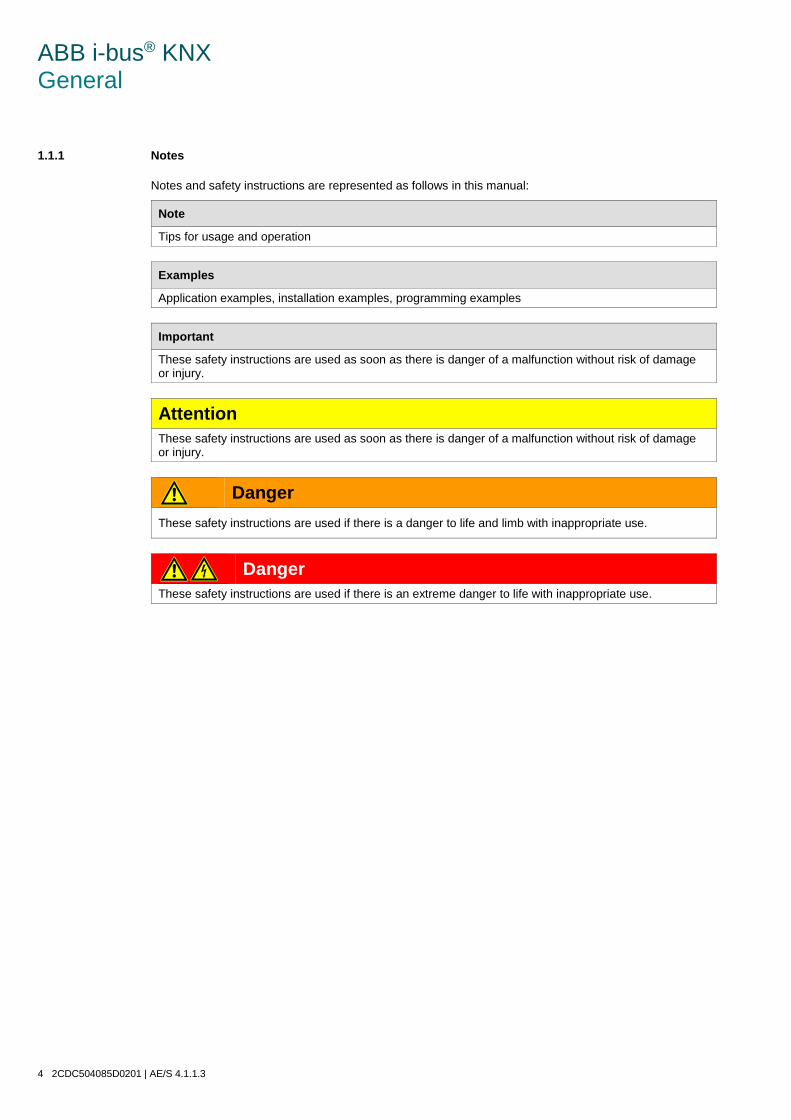
ABB i-bus® KNX General 1.1.1 Notes
Notes and safety instructions are represented as follows in this manual:
Note
Tips for usage and operation
Examples
Application examples, installation examples, programming examples
Important
These safety instructions are used as soon as there is danger of a malfunction without risk of damage or injury.
Attention These safety instructions are used as soon as there is danger of a malfunction without risk of damage or injury.
Danger These safety instructions are used if there is a danger to life and limb with inappropriate use.
Danger These safety instructions are used if there is an extreme danger to life with inappropriate use.
4 2CDC504085D0201 | AE/S 4.1.1.3

ABB i-bus® KNX General 1.2 Product and functional overview
The device is a modular installation device with a module width of 4 space units in Pro M design for installation in distribution boards. The connection to the ABB i-bus® is established using a bus connection terminal on the front side. The assignment of the physical address, as well as the setting of parameters, is carried out with Engineering Tool Software ETS.
• The device enables you to record and process four analogue input signals in accordance with DIN IEC 60381, e.g. 0…1 V, 0…5 V, 0…10 V, 1…10 V, 0…20 mA, 4…20 mA. Furthermore, PT 100 and PT 1000 sensors in 2- and 3-conductor technology, 0...1,000 ohm resistors and a selection of KTY sensors can be connected. It is also possible to adapt the device to user-defined KTY sensors by entering a characteristic curve. Floating contacts can also be connected to the device.
• The processing of the input signals is carried out in the application Threshold measurement 4f.
• The object values can be set for each input separately in the application. The output value can be sent as a 1-bit value, or a 1-, 2- or 4-byte value via the bus.
• Due to the flexibility allowing the measurement curve to be adapted, it is possible to mask out certain areas of the measurement curve or to even offset or correct them. Measured values can be averaged over 1, 4, 16 or 64 measurements using the Filter function. The output value is “smoothed” via the mean value. As one measurement is taken every second, the setting for 64 measurements per output means that the output value is sent after about 64 seconds.
• It is possible to set two thresholds per input. The thresholds each have an upper and lower limit which can be set independently. The thresholds themselves can be changed via the bus.
• There are four further calculation objects available. It is thus possible to compare two output values or calculate the arithmetic mean. The options less than, greater than, addition, subtraction and averaging are available.
Important
To ensure that all programmable functions work correctly, be sure to observe the sensor manufacturer's technical data
AE/S 4.1.1.3 | 2CDC504085D0201 5

ABB i-bus® KNX General 1.2.1 Integration in the i-bus® Tool
The device possesses an interface to the i-bus® Tool.
The i-bus® Tool can be used to change settings on the connected device.
The i-bus® Tool can be downloaded for free from our website (www.abb.com/knx).
ETS is not required for the i-bus® Tool. However, Falcon Runtime (version 1.6 or higher and version 1.8 or higher for Windows 7) must be installed to set up a connection between the PC and KNX.
A description of the functions can be found in the online help of the i-bus® Tool.
6 2CDC504085D0201 | AE/S 4.1.1.3

ABB i-bus® KNX Device technology 2 Device technology
Analogue Input AE/S 4.1.1.3
The device is used to record analogue data. Four conventional sensors can be connected to the device. The connection to the bus is established via the bus connection terminal on the front of the device.
The device is ready for operation after connecting the bus voltage. Additional auxiliary voltage is required. The device is parameterized and programmed using ETS.
2.1 Technical data
Supply Bus voltage 21…32 V DC Current consumption, bus < 10 mA Mains voltage US 85…265 V AC, 110…240 V DC, 50/60 Hz Power consumption Max. 11 W at 230 V AC Power consumption, mains 80/40 mA at 115/230 V AC Leakage loss, device Max. 3 W at 230 V AC Auxiliary voltage supply for the sensors Rated voltage Un 24 VDC Rated current In 300 mA Connections KNX Via bus connection terminal, screwless Mains voltage Via screw terminals Sensor supply Via screw terminals Sensor inputs Via screw terminals Screw terminals 0.2…2.5 mm2 fine stranded
0.2…4.0 mm2 single core Tightening torque Max. 0.6 Nm Cable length Between sensor and device input Max. 100 m Operating and display elements Programming button/LED For assignment of the physical address Protection type IP 20 To DIN EN 60 529 Protection class II To DIN EN 61 140 Isolation category Overvoltage category III to EN 60 664-1 Pollution degree II to DIN EN 60 664-1 KNX safety voltage SELV 24 V DC
2CD
C07
1016
S001
4
AE/S 4.1.1.3 | 2CDC504085D0201 7

ABB i-bus® KNX Device technology Temperature range Operation -5 °C…+45 °C Storage -25…+55 °C Transport -25…+70 °C Ambient conditions Maximum air humidity 93 %, no condensation allowed Design Modular installation device (MDRC) Modular installation device, Pro M Dimensions 90 x 72 x 64.5 mm (H x W x D) Mounting width in space units 4 x 18 mm modules Mounting depth 64.5 mm Mounting On 35 mm mounting rail To DIN EN 60 715 Installation position Any Weight 0.27 kg Housing/color Plastic housing, gray Approvals KNX to EN 50 090-1, -2 Certification CE mark In accordance with the EMC guideline and low
voltage guideline
8 2CDC504085D0201 | AE/S 4.1.1.3

ABB i-bus® KNX Device technology 2.1.1 Inputs
Rated values Quantity 4 Voltage 0…1 V, 0…5 V, 0…10 V, 1…10 V Maximum upper limit 12 V Current 0...20 mA, 4...20 mA Maximum upper limit 25 mA Resistance 0…1,000 ohms
PT100 2-conductor technology PT100 3-conductor technology PT1000 2-conductor technology PT1000 3-conductor technology Choice of KT/KTY 1000/2000, user-defined
Contact Floating Input resistance for voltage measurement > 50 Mohms Input resistance for current measurement 260 ohms Permitted cable length between sensor and
device input Max. 100 m
Device type Application Max. number of
communication objects Max. number of group addresses
Max. number of assignments
AE/S 4.1.1.3 Threshold measurement 4f/...* 42 100 100
* … = Current version number of the application. Please refer to the software information on our website for this purpose.
Note
ETS and the current version of the device application are required for programming. The current application can be found with the respective software information for download on the Internet at www.abb.com/knx. After import into ETS, the application appears in the Catalogs window under Manufacturers/ABB/Analogue Input, 4-fold-MDRC. The device does not support the locking function of a KNX device in ETS. If you use a BCU code to inhibit access to all the project devices, this has no effect on this device. Data can still be read and programmed.
AE/S 4.1.1.3 | 2CDC504085D0201 9

ABB i-bus® KNX Device technology 2.2 Resolution and accuracy and tolerances
Please note that the tolerances of the sensors which are used will need to be added to the listed values.
With sensors based on resistance measurement, it is also necessary to consider the feeder cable errors.
In the supplied state of the device, the stated accuracies will not be initially achieved. After initial commissioning, the device performs an autonomous calibration of the analogue measurement circuit. This calibration takes about an hour and is performed in the background. It is undertaken regardless of whether or not the device is parameterized and is independent of the connected sensors. The normal function of the device is not affected. After calibration has been completed, the calibration values which have been determined will be stored in the non-volatile memory. Thereafter, the device will achieve this level of accuracy every time it is switched on. If the calibration is interrupted by programming or bus failure, it will recommence every time it is restarted. The ongoing calibration is displayed in the Status byte by a 1 in bit 4.
Important
The Analogue Input has a Un = 24 V DC output voltage to power the sensors. Make sure that the maximum output current is not exceeded.
10 2CDC504085D0201 | AE/S 4.1.1.3

ABB i-bus® KNX Device technology 2.2.1 Voltage signals
Sensor signal Resolution Accuracy at 25 °C TU*1
Accuracy at -5…45 °C TU*1
Accuracy at -20…70 °C Tu*1
Remark
0…1 V 200 µV ±0.2 % ±1 mV
±0.5 % ±1 mV
±0.8 % ±1 mV
0…5 V 200 µV ±0.2 % ±1 mV
±0.5 % ±1 mV
±0.8 % ±1 mV
0…10 V 200 µV ±0.2 % ±1 mV
±0.5 % ±1 mV
±0.8 % ±1 mV
1…10 V 200 µV ±0.2 % ±1 mV
±0.5 % ±1 mV
±0.8 % ±1 mV
*1 of current measured value at ambient temperature (TU)
2.2.2 Current signals
Sensor signal Resolution Accuracy at 25 °C TU*2
Accuracy at -5…45 °C Tu*2
Accuracy at -20…70 °C Tu *2
Remark
0…20 mA 2 µA ±0.2 % ±4 µA
±0.5 % ±4 µA
±0.8 % ±4 µA
4…20 mA 2 µA ±0.2 % ±4 µA
±0.5 % ±4 µA
±0.8 % ±4 µA
*2 of current measured value at ambient temperature (TU)
2.2.3 Resistance signals
Sensor signal Resolution
Accuracy at 25 °C TU*3
Accuracy at -5…45 °C Tu *3
Accuracy at -20…70 °C Tu *3
Remark
0…1,000 ohms 0.1 ohm ±1.0 ohm ±1.5 ohms ±2 ohms
PT100*4 0.01 ohm ±0.15 ohm ±0.2 ohm ±0.25 ohm 0.1 ohm = 0.25 °C
PT1000*4 0.1 ohm ±1.5 ohms ±2.0 ohms ±2.5 ohms 1 ohm = 0.25 °C
KT/KTY 1,000*4 1 ohm ±2.5 ohms ±3.0 ohms ±3.5 ohms 1 ohm = 0.125 °C/at 25 °C
KT/KTY 2,000*4 1 ohm ±5 ohms ±6.0 ohms ±7.0 ohms 1 ohm = 0.064 °C/at 25 °C
*3 in addition to current measured value at ambient temperature (TU) *4 plus feeder cable and sensor faults
AE/S 4.1.1.3 | 2CDC504085D0201 11

ABB i-bus® KNX Device technology
PT100 The PT100 is precise and exchangeable but subject to faults in the feeder cables (cable resistance and heating of the feeder cables). A terminal resistance of just 200 milliohm causes a temperature error of 0.5 °C.
PT1000 The PT1000 responds just like the PT100, but the influences of feeder cable errors are lower by a factor of 10. Use of this sensor is preferred.
KT/KTY The KT/KTY has a low level of accuracy, can only be exchanged under certain circumstances and can only be used for very simple applications.
Please note that there are different tolerance classes for the sensors in the versions PT100 and PT1000.
The table indicates the individual classes:
Designation Tolerance DIN class A 0.15 + (0.002 x t)
1/3 DIN class B 0.10 + (0.005 x t)
1/2 DIN class B 0.15 + (0.005 x t)
DIN class B 0.30 + (0.005 x t)
2 DIN class B 0.60 + (0.005 x t)
5 DIN class B 1.50 + (0.005 x t)
t = Current temperature
12 2CDC504085D0201 | AE/S 4.1.1.3

ABB i-bus® KNX Device technology 2.3 Connection schematics
Connecting sensor with an external supply Connecting a floating contact
Connecting a 3-conductor sensor with its own power supply
Connecting a 4-conductor sensor with its own power supply
2CD
C07
2034
F001
3
2C
DC
0720
37F0
013
2C
DC
0720
36F0
013
2C
DC
0720
35F0
013
AE/S 4.1.1.3 | 2CDC504085D0201 13

ABB i-bus® KNX Device technology
Connecting a 4…20 mA sensor Connecting a PT100/PT1000 3-conductor temperature sensor
1 Label carrier
2 Programming button
3 Programming LED (red)
4 Bus connection terminal
5 Power supply
6 Auxiliary voltage output for sensor supply
7 Sensor input
2
CD
C07
2032
F001
4
2C
DC
0720
31F0
014
14 2CDC504085D0201 | AE/S 4.1.1.3

ABB i-bus® KNX Device technology 2.4 Dimension drawing
2C
DC
0720
39F0
013
AE/S 4.1.1.3 | 2CDC504085D0201 15

ABB i-bus® KNX Device technology 2.5 Mounting and installation
The device is a modular installation device for quick installation in distribution boards on 35 mm mounting rails to DIN EN 60 715.
The installation position can be selected as required.
The electrical connection is implemented using screw terminals. The connection to the bus is implemented using the supplied bus connection terminal. The terminal assignment is located on the housing.
The device is ready for operation once the mains voltage and the bus voltage have been applied.
Accessibility to the device for the purpose of operation, testing, visual inspection, maintenance and repair must be provided compliant to DIN VDE 0100-520.
Attention The sensor manufacturer's technical data must be observed for optimum measuring or monitoring values. The same applies to the specifications with regard to equipment for lightning protection.
Commissioning requirement In order to commission the device, a PC with ETS as well as a connection to the ABB i-bus®, e.g. via a KNX interface, is required.
The device is ready for operation after connection to the bus voltage. Additional auxiliary voltage is required.
Important
The maximum permissible current of a KNX line must not be exceeded. During planning and installation ensure that the KNX line is correctly dimensioned. The device features a maximum current consumption of 12 mA.
Mounting and commissioning may only be carried out by electrical specialists. The appropriate standards, guidelines, regulations and specifications for the appropriate country should be observed when planning and setting up electrical installations and security systems for intrusion and fire detection.
• Protect the device from damp, dirt and damage during transport, storage and operation.
• Only operate the device within the specified technical data!
• The device should only be operated in an enclosed housing (distribution board)!
• The voltage supply to the device must be switched off before mounting work is performed.
Danger All poles must be disconnected when expanding or modifying the electrical connections.
16 2CDC504085D0201 | AE/S 4.1.1.3

ABB i-bus® KNX Device technology
Supplied state The device is supplied with the physical address 15.15.255. The application is pre-installed. It is therefore only necessary to load group addresses and parameters during commissioning.
The complete application can be reloaded if required. Downloads may take longer after a change of application or a discharge.
Assignment of the physical address The assignment and programming of the physical address is carried out in ETS.
The device features a Programming button for assignment of the physical address. The red Programming LED lights up after the button has been pressed. It goes off as soon as ETS has assigned the physical address or the Programming button is pressed again.
Download reaction Depending on the PC which is used, the progress bar for the download may take up to one and a half minutes to appear, due to the complexity of the device.
Cleaning The voltage supply to the device must be switched off before cleaning. If devices become dirty, they can be cleaned using a dry cloth or a cloth dampened with a soapy solution. Corrosive agents or solutions should never be used.
Maintenance The device is maintenance-free. In the event of damage repairs should only be carried out by an authorized person, e.g. during transport and/or storage.
AE/S 4.1.1.3 | 2CDC504085D0201 17


ABB i-bus® KNX Commissioning 3 Commissioning
The Threshold measurement 4f application and ETS Engineering Tool Software are used to parameterize the device. The application provides the device with a comprehensive and flexible range of functions. The standard settings allow simple commissioning. The functions can be expanded if required.
3.1 Overview
The following functions can be selected for each of the four inputs:
Sensor type (type of input signal)
All conventional sensors with an output signal of 0…1 V, 0…5 V, 0…10 V, 1…10 V, 0…20 mA, 4…20 mA, 0…1,000 ohms, 2-conductor PT100s and 2- and 3-conductor PT1000s or a range of KT/KTY sensors can be connected. Furthermore, user-defined KTY sensors can be matched to the Analogue Input. Floating contacts also be processed.
Signal correction/ displacement
The sensor signal can be corrected or displaced.
Measuring range Flexible setting option for the upper and lower measuring limits dependent on the sensor’s output signal. The measuring curve can be linearly adapted between the upper and lower measuring limits.
Output value Flexible setting options for the output value – upper and lower measuring limits dependent on the sensor’s output signal.
Data types of the output value
The output value can be sent as a 1-bit value [0/1], 1-byte value [0...+255], 1-byte value [-128...+127], 2-byte value [0...+65,535], 2-byte value [-32,768...+32,767], 2-byte value (floating point) or 4-byte value (IEEE floating point).
Filtering The output value is "smoothed" via the mean value. The mean value can be calculated over 1, 4, 16 or 64 measurements. A measurement is taken once per second.
Threshold Two thresholds can be set, each with an upper and lower limit. The limits can be modified via the bus.
Calculation There are four calculation objects available. It is thus possible to compare two output values or calculate the arithmetic mean. The options less than, greater than, addition, subtraction and averaging are available.
AE/S 4.1.1.3 | 2CDC504085D0201 19

ABB i-bus® KNX Commissioning 3.1.1 Conversion
For ABB i-bus® KNX devices, it is possible to adopt the parameter settings and group addresses from earlier versions of the application from ETS3.
Furthermore, conversion can be used to transfer the existing parameterization of a device to a different device.
Note
When the term "channels" is used in ETS, it always means inputs and/or outputs. To make the language of ETS generally valid for as many ABB i-bus® devices as possible, the word "channels" is used in this document.
The following applications can be fully converted:
• Threshold measurement 2f/1.0b (AE/A 2.1) to Threshold measurement 4f/1.0 (AE/S 4.1.1.3)
Note
If the number of channels on the target device is larger than the number of inputs/outputs of the source device, only the first inputs/outputs of the target device are written with the converted data from the source device. The remaining inputs/outputs retain or are reset to the default values. Default values for newly added parameters are set after conversion.
Inputs a and b of the AE/A 2.1 Analogue Input's application become the same inputs in the AE/S 4.1.1.3's application. Inputs c and d of the AE/S 4.1.1.3 remain unused.
The parameters Mains frequency and Enable communication object "In operation", 1 bit are not available in the AE/A 2.1 and after conversion they retain the standard values of the AE/S 4.1.1.3.
20 2CDC504085D0201 | AE/S 4.1.1.3

ABB i-bus® KNX Commissioning 3.1.1.1 Conversion procedure
• Import the current application into ETS.
• Insert the desired device into your project.
• Perform your parameterizations and program the device.
• Right-click the product and select Plug-in > Convert in the context menu.
• Then make the desired settings in the Convert dialog.
• Finally, replace the physical address and delete the old device.
AE/S 4.1.1.3 | 2CDC504085D0201 21

ABB i-bus® KNX Commissioning 3.2 Parameters
The ETS Engineering Tool Software is used for parameterizing the device.
The application is in the ETS Catalogs window under Manufacturers/ABB/Analogue Input, 4-fold-MDRC.
The following chapter describes the parameters of the device using the parameter windows. Parameter windows are structured dynamically so that further parameters may be enabled depending on the parameterization and the function.
The default values of the parameters are underlined, e.g.:
Options: Yes No
22 2CDC504085D0201 | AE/S 4.1.1.3

ABB i-bus® KNX Commissioning 3.2.1 Parameter window General
Higher level parameters can be set in the General parameter window.
Consider the sensor manufacturer for the parameter settings.
Important
The specifications of the sensor manufacturer must be observed to ensure perfect functioning of the Analogue Input. Furthermore, the manufacturer’s specifications should be consulted for the parameter settings. On the connected sensors, ensure, for example, that the upper limits of 12 V with voltage signals and 25 mA with current signals are not exceeded.
AE/S 4.1.1.3 | 2CDC504085D0201 23

ABB i-bus® KNX Commissioning
Reaction on bus voltage recovery (when mains voltage is applied)
Reaction on programming/ETS reset (when mains voltage is applied) Options: No reaction Send object values immediately Send object values with a delay The parameters are used to set the reaction on bus voltage recovery/reaction on programming/ETS reset when mains voltage is applied.
• No reaction: No object values are sent. After bus voltage recovery, programming or ETS reset, none of the object values (output values, thresholds, calculation values, measured value out of range, In operation and Status byte) are sent on the bus, i.e. a visualization is not refreshed. The object values are sent at the earliest after the parameterized settings are sent on the bus.
• Send object values immediately: The object values are sent immediately. After bus voltage recovery, programming or ETS reset, the individual object values (output values, thresholds, calculation values, measured value out of range, In operation and Status byte) are sent on the bus. This ensures, for example, that visualizations display a current process map.
• Send object values with a delay: The object values are sent after a delay. After bus voltage recovery, programming or ETS reset, the individual object values (output values, thresholds, calculation values, measured value out of range, In operation and Status byte) are sent on the bus after a delay. Thus the process map is sent after a delay, e.g. to control the bus load in a KNX system.
The Send delay is set separately and applies to both the parameters Reaction on bus voltage recovery and Reaction on programming/ETS reset.
24 2CDC504085D0201 | AE/S 4.1.1.3

ABB i-bus® KNX Commissioning
How does the device react if bus voltage recovers before the mains voltage? As the circuit is supplied with power from the mains voltage, it cannot react to the bus voltage recovery. The circuit cannot be activated.
If the mains voltage recovers and the bus voltage is already available then the reaction after mains voltage recovery is undertaken.
How does the device react if mains voltage recovers before the bus voltage? Case 1: Option Send object values immediately
The telegrams are sent immediately. As the bus voltage is still absent, no telegrams are visible. Should the bus voltage then recover, the reaction in accordance with the setting of the option for bus voltage recovery is applied.
Case 2: Option Send object values with a delay
The reaction depends on the option for bus voltage recovery.
Option No reaction
The ongoing send delay is not interrupted.
Option Send object values immediately
The ongoing send delay is interrupted and sending is implemented immediately.
Option Send object values with a delay
The ongoing send delay is retriggered. Sending is undertaken after the new send delay time.
How does sending values function? Generally, the send options of the individual sensors tend to overlap with the options that are possible for mains voltage recovery or programming.
Example
If the temperature sensor is parameterized to send cyclically every 5 seconds, it will do so after mains voltage recovery, regardless of the option selected for mains voltage recovery.
With the options in parameter Reaction on..., it is possible after an event (mains voltage recovery, programming and bus voltage recovery) that the complete process map of the sensor (output values and thresholds) is either sent immediately or after a defined send delay. This ensures that all relevant information is guaranteed to be sent at least once after an event (e.g. for use by a visualization system).
What is an ETS reset? Generally an ETS reset is defined as a reset of the device via the ETS. The ETS reset is triggered in the ETS under the menu item Commissioning with the function Reset device. This stops and restarts the application.
AE/S 4.1.1.3 | 2CDC504085D0201 25

ABB i-bus® KNX Commissioning
Send delay for above parameters Options: 5 s/10 s/20 s/30 s/60 s The send delay time determines the time between bus voltage recovery, programming/ETS reset and the time from which the telegrams should be sent with a delay. When the device has been started, the following communication objects also send a telegram after the set delay.
• The In Operation – General communication object sends an In operation telegram with the value 1 or 0 (adjustable).
• The Status byte – General communication object sends a Status byte telegram with the current value (state). Each bit is assigned with information.
For further information see: Appendix
Note
The settings in the parameters only have an effect on the parameters Reaction on bus voltage recovery and Reaction on programming/ETS reset. If the option No reaction is set in each of the parameters, the selected send delay has no function. No telegrams are sent during the send delay in progress in the initialization phase. Value Read telegrams are also answered during the delay time. Incoming telegrams to the communication object, e.g. Request output value, are not considered here. The send delay times should be coordinated to the entire KNX system.
How does the send delay function? The sensor inputs are evaluated and telegrams are received during the send delay. The received telegrams are processed immediately, and the object values of the outputs change immediately if necessary. However, no telegrams are sent on the bus.
If during the Send delay objects are read via the Value Read telegrams, e.g. by visualization systems, immediately thereafter the corresponding Value Respond telegrams are sent and not just after the Send delay has timed out.
After the Send delay has timed out, all object values to be sent are sent on the bus.
Mains frequency Options: 50 Hz 60 Hz This parameter defines the mains frequency.
Rate of telegrams Options: 1/2/3/5/10/20 telegrams/second To control the bus load, this parameter can be used to limit the rate of telegrams per second.
Example
With the setting 5 telegrams/second a maximum of five telegrams can be sent in a second.
26 2CDC504085D0201 | AE/S 4.1.1.3

ABB i-bus® KNX Commissioning
Enable communication object "In operation", 1-bit Options: No Yes • Yes: The 1-bit communication object In operation is enabled.
Dependent parameter:
Send Options: Value 0 Value 1
Sending cycle time in s [1...65,535] Options: 1...60...65,535 Here a time interval is set, which the communication object In operation uses to cyclically send a telegram.
Note
After bus voltage recovery, the communication object sends its value after the set sending and switching delay time.
Designation, Input a, b, c, d (40 characters) Options: < Text > With this parameter, it is possible to enter a text of up to 40 characters in length for identification in the ETS.
Note
The text field allows you to enter information such as which function is assigned to which input. The text is purely for informative purposes and has no further function.
AE/S 4.1.1.3 | 2CDC504085D0201 27

ABB i-bus® KNX Commissioning 3.2.2 Parameter window a: General
with sensor type: Temperature-dependent resistance
Setting options for sensor type Temperature-dependent resistance.
The specifications below also apply to parameter windows b...d: General.
Use input Options: No Yes The parameter enables input a.
As a result, further parameters and communication objects become visible.
Sensor type Options: Current/Voltage/Resistance Temperature-dependent resistance Floating contact scanning The Sensor type is set with this parameter.
Selection of option Temperature-dependent resistance.
Dependent parameters:
Sensor output Options: PT100 2-cond. technology [-50…+150 °C] PT1000 2-cond. technology [-50…+150 °C] PT100 3-cond. technology [-50…+150 °C] PT1000 3-cond. technology [-50…+150 °C] KT/KTY [-50…+150 °C] The Sensor output is set with this parameter. The data can be found in the sensor manufacturer's technical documentation.
28 2CDC504085D0201 | AE/S 4.1.1.3

ABB i-bus® KNX Commissioning 3.2.2.1 Sensor output parameter option: PT100/PT1000 2-cond. technology
Send output value as This parameter is fixed to 2-byte (floating point).
What is the output value? The Analogue Input records a sensor measured value, converts it according to the set parameters and sends it on the bus. This sent value is designated as the output value.
Temp. offset in 0.1 K [-50...+50] Options: -50...0...+50 A maximum offset of ± 5 K (Kelvin) can be added to the recorded temperature with this parameter.
Line fault compensation Options: None Via cable length Via cable resistance This parameter is used for setting the line fault compensation.
Selection of options Via cable length and Via cable resistance: For a description, see Chapter Line fault compensation Via cable length, p. 34 and Chapter Line fault compensation Via cable resistance, p. 35.
AE/S 4.1.1.3 | 2CDC504085D0201 29

ABB i-bus® KNX Commissioning 3.2.2.2 Parameter option Sensor output: PT100/PT1000 3-cond. technology
Note
For a description of the parameters, see Chapter Sensor output parameter option: PT100/PT1000 2-cond. technology, p. 29.
On selecting a 3-conductor PT100 or PT1000 the following information also appears:
Input b must also be configured as 3-conductor measurement
Input b is used for line fault compensation
30 2CDC504085D0201 | AE/S 4.1.1.3

ABB i-bus® KNX Commissioning
3-conductor connection:
Note
With the 3-conductor connection the following applies: • Input a or c always measures the measuring resistor. • Input b or d always measures the cable resistance. When a 3-conductor connection is selected, inputs b and d are visible in the communication objects. If a group address is linked to these inputs, then the measured cable resistance is transmitted. It should be noted that the temperature value must be converted with the DPT 9.001, so that the resistance value remains intact.
AE/S 4.1.1.3 | 2CDC504085D0201 31

ABB i-bus® KNX Commissioning 3.2.2.3 Parameter option Sensor output: KT/KTY [-50…+150 °C]
Manufacturer designation Options: KT 100 / 110 / 130 KT 210 / 230 KTY 10-5 / 11-5 / 13-5 KTY 10-6 / 10-62 / 11-6 / 13-6 / 16-6 / 19-6 KTY 10-7 / 11-7 / 13-7 KTY 21-5 / 23-5 KTY 21-6 / 23-6 KTY 21-7 / 23-7 KTY 81-110 / 81-120 / 81-150 KTY 82-110 / 82-120 / 82-150 KTY 81-121 / 82-121 KTY 81-122 / 82-122 KTY 81-151 / 82-151 KTY 81-152 / 82-152 KTY 81-210 / 81-220 / 81-250 KTY 82-210 / 82-220 / 82-250 KTY 81-221 / 82-221 KTY 81-222 / 82-222 KTY 81-251 / 82-251 KTY 81-252 / 82-252 KTY 83-110 / 83-120 / 83-150 KTY 83-121 KTY 83-122 KTY 83-151 User-defined For selection of a predefined KTY sensor
Note
If a KTY sensor which is not in the list is used, the option User-defined can be used to enter its characteristic, see following page.
32 2CDC504085D0201 | AE/S 4.1.1.3

ABB i-bus® KNX Commissioning
User-defined
The following ohmic values must rise to higher temperatures <- Note
To ensure correct functioning of the Analogue Input with respect to the user-defined entries, the ohm (resistance) values as visible for the preset values must be in ascending order.
An incorrect entry can lead to unrealistic output values!
Resistance in ohms at -50…+150 °C Options: 0…1,030…4,280…5,600 A resistance characteristic can be entered via these 11 parameters. The data can be found in the sensor manufacturer's technical documentation.
Note
The description of the parameters Send output value as, Temperature offset and Line fault compensation can be found in Parameter window a: General with sensor type: Temperature-dependent resistance.
AE/S 4.1.1.3 | 2CDC504085D0201 33
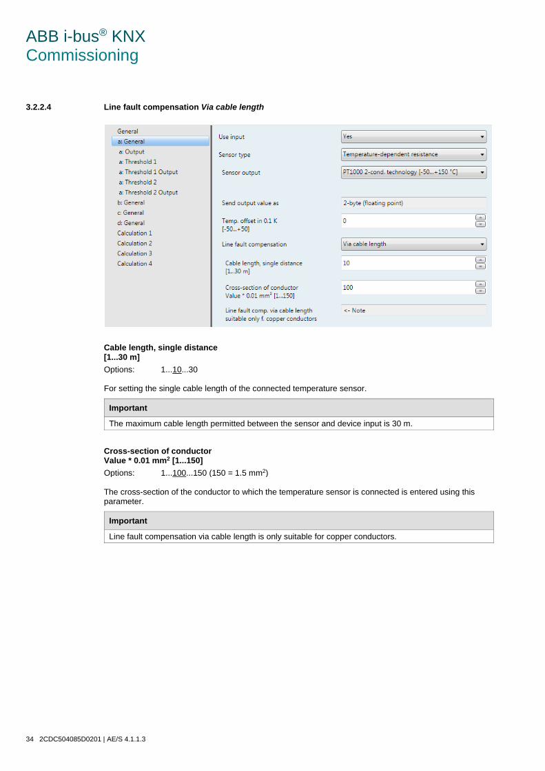
ABB i-bus® KNX Commissioning 3.2.2.4 Line fault compensation Via cable length
Cable length, single distance [1...30 m] Options: 1...10...30 For setting the single cable length of the connected temperature sensor.
Important
The maximum cable length permitted between the sensor and device input is 30 m.
Cross-section of conductor Value * 0.01 mm2 [1...150] Options: 1...100...150 (150 = 1.5 mm2) The cross-section of the conductor to which the temperature sensor is connected is entered using this parameter.
Important
Line fault compensation via cable length is only suitable for copper conductors.
34 2CDC504085D0201 | AE/S 4.1.1.3

ABB i-bus® KNX Commissioning 3.2.2.5 Line fault compensation Via cable resistance
Cable resistance in milliohms (total of forw. and ret. conduct.) Options: 0...500...10,000 Using this parameter the level of cable resistance of the connected temperature sensor is set.
Important
In order to correctly measure the cable resistance, the conductors must be shorted together at the end of the cable and should not be connected to the Analogue Input.
AE/S 4.1.1.3 | 2CDC504085D0201 35

ABB i-bus® KNX Commissioning 3.2.2.6 Parameter window a: Output
This parameter window is enabled if the parameter Use input has been set to Yes in Parameter window a: General with sensor type: Temperature-dependent resistance, p. 28.
Scan rate The sensor signal of input is measured once per second.
Filter Options: Inactive Low (mean value over 4 measurements) Medium (mean value over 16 measurements) High (mean value over 64 measurements) This parameter is used for setting a filter (floating mean value filter). This can be used to set the output value as a mean value using three different options.
• Inactive: Filter is not active
• Low: Mean output value over 4 measurements
• Medium: Mean output value over 16 measurements
• High: Mean output value over 64 measurements
Important
By use of the filter the output value is “smoothed” via the mean value and is available for further processing. The filter thus has immediate effects on the thresholds and calculation values. The higher the degree of the filtering applied, the smoother the result. This means that the changes to the output values become slower. Example: An erratic change of the sensor signal with the setting Medium will take 16 seconds until the output value is through.
36 2CDC504085D0201 | AE/S 4.1.1.3
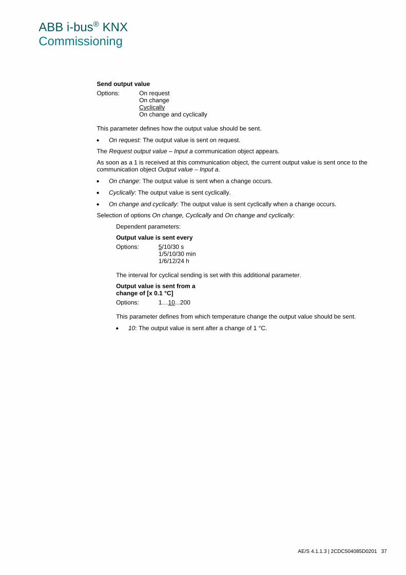
ABB i-bus® KNX Commissioning
Send output value Options: On request On change Cyclically On change and cyclically This parameter defines how the output value should be sent.
• On request: The output value is sent on request.
The Request output value – Input a communication object appears.
As soon as a 1 is received at this communication object, the current output value is sent once to the communication object Output value – Input a.
• On change: The output value is sent when a change occurs.
• Cyclically: The output value is sent cyclically.
• On change and cyclically: The output value is sent cyclically when a change occurs.
Selection of options On change, Cyclically and On change and cyclically:
Dependent parameters:
Output value is sent every Options: 5/10/30 s 1/5/10/30 min 1/6/12/24 h The interval for cyclical sending is set with this additional parameter.
Output value is sent from a change of [x 0.1 °C] Options: 1…10...200 This parameter defines from which temperature change the output value should be sent.
• 10: The output value is sent after a change of 1 °C.
AE/S 4.1.1.3 | 2CDC504085D0201 37

ABB i-bus® KNX Commissioning 3.2.2.7 Parameter window a: Threshold 1
The details in the following also apply to a: Threshold 2.
Use threshold Options: No Yes This parameter defines if threshold 1 should be used. If Yes is selected, the communication object Threshold – Input a Threshold 1 appears.
Tolerance band lower limit Input in 0.1 °C Options: -500…1500
Tolerance band upper limit Input in 0.1 °C Options: -500…1500 The upper and lower limits of the tolerance band are set via these two parameters.
The entry is made in steps of 0.1 °C, i.e. an entry of 1500 means 150 °C. For further information see: Appendix
38 2CDC504085D0201 | AE/S 4.1.1.3

ABB i-bus® KNX Commissioning
Limits modifiable via bus Options: No Yes This parameter specifies whether the limits can be changed via the bus.
• Yes: The following communication objects appear:
Modify – Input a Threshold 1 lower limit
Modify – Input a Threshold 1 upper limit.
Important
The value formats of these communication objects are the same as the format set in parameter window a: General, under the parameter Send output value as (see Parameter window a: General with sensor type: Temperature-dependent resistance, p. 28).
Data type of threshold object Options: 1-bit 1-byte [0...+255] Selection of option 1-bit:
Dependent parameters:
Send if threshold fallen below Options: Do not send telegram Send ON telegram Send OFF telegram
Send if threshold exceeded Options: Do not send telegram Send ON telegram Send OFF telegram • Do not send telegram: There is no reaction.
• Send ON telegram: A telegram with the value 1 is sent.
• Send OFF telegram: A telegram with the value 0 is sent.
Min. duration of the undershoot
Min. duration of the overshoot Options: None 5/10/30 s 1/5/10/30 min 1/6/12/24 h • None: the threshold is sent directly.
With the further time options, a minimum duration can be selected. If the send condition reverts during the minimum duration, no telegrams are sent.
AE/S 4.1.1.3 | 2CDC504085D0201 39

ABB i-bus® KNX Commissioning
Selection of option 1-byte [0...+255]:
Dependent parameters:
Send if threshold fallen below [0...+255] Options: 0...255
Send if threshold exceeded [0...+255] Options: 0...255 A value of 0 to 255 can be entered in single steps.
Min. duration of the undershoot
Min. duration of the overshoot Options: None 5/10/30 s 1/5/10/30 min 1/6/12/24 h • None: the threshold is sent directly.
With the further time options, a minimum duration can be selected. If the send condition reverts during the minimum duration, no telegram is sent.
40 2CDC504085D0201 | AE/S 4.1.1.3

ABB i-bus® KNX Commissioning 3.2.2.8 Parameter window a: Threshold 1 Output
The details in the following also apply to a: Threshold 2 Output.
Send threshold object Options: On change On change and cyclically This parameter is used to specify the send behavior of the threshold object.
• On change: The threshold object is sent when a change occurs.
• On change and cyclically: The threshold object is sent cyclically when a change occurs. The threshold object is sent cyclically until the value falls below or exceeds the other limit.
Dependent parameters:
Send if threshold fallen below every
Send if threshold exceeded every Options: 5/10/30 s 1/5/10/30 min 1/6/12/24 h These two parameters are used to define the point to which cyclical sending should take place after an undershoot of the lower limit or an overshoot of the upper limit.
AE/S 4.1.1.3 | 2CDC504085D0201 41

ABB i-bus® KNX Commissioning 3.2.3 Parameter window a: General
with sensor type: Current/Voltage/Resistance
Setting options with sensor type Current/Voltage/Resistance.
The specifications below also apply to parameter windows b...d: General.
Use input Options: No Yes The parameter enables input a.
As a result, further parameters and communication objects become visible.
Sensor type Options: Current/Voltage/Resistance Temperature-dependent resistance Floating contact scanning The Sensor type is set with this parameter.
Selection of option Current/Voltage/Resistance
Dependent parameters:
42 2CDC504085D0201 | AE/S 4.1.1.3

ABB i-bus® KNX Commissioning
Sensor output Options: 0…1 V 0…5 V 0…10 V 1…10 V 0…20 mA 4…20 mA 0…1,000 ohms With this parameter the input range of the connected sensor is set to the Sensor output.
Send output value as Options: 1-byte [0...+255] 1-byte [-128...+127] 2-byte [0...+65,535] 2-byte [-32,768…+32,767] 2-byte (floating point) 4-byte (IEEE floating point) This parameter defines in which format the Output value should be sent.
If the option 2-byte (floating point) or 4-byte (IEEE floating point) is set, a further parameter will also appear at the bottom of the parameter window.
What is the output value? The Analogue Input records a sensor measured value, converts it according to the set parameters and sends it on the bus. This sent value is designated as the output value.
AE/S 4.1.1.3 | 2CDC504085D0201 43

ABB i-bus® KNX Commissioning
Measuring range definition
The following four parameters are dependent on the parameter Send output value as.
The preset values change dependent on the selected option. With the options 2-byte (floating point) or 4-byte (IEEE floating point) the additional Factor parameter appears.
The following description is an example for all adjustable options.
44 2CDC504085D0201 | AE/S 4.1.1.3

ABB i-bus® KNX Commissioning
Lower meas. limit in x % of meas. range end value Options: 0...100
Upper meas. limit in x % of meas. range end value Options: 0...100 Using both of these parameters the lower and upper measuring limits in x % of the measuring range end value are set. If the set upper and lower measuring limits are exceeded or not achieved, the communication object Measured value out of range – Input a sends a 1. If the measured value is back between the limits, the communication object sends a 0.
What is the measuring range end value? The measuring range end value is used to define the maximum voltage, current, resistance value or temperature value which is set in the Sensor output parameter, e.g. a sensor with signal output from 0...10 V has a measuring range end value of 10 V.
Output value to be sent for lower measuring limit [0...+255] Options: 0...255
Output value to be sent for upper measuring limit [0...+255] Options: 0...255 Using both these parameters the Output values to be sent for upper and lower measuring limits [0...+255] are set. The measuring curve between the upper and lower measuring limits is linear.
What is the measuring limit? Using the measuring limit, you define up to which set values the Analogue Input is to evaluate the signal of the connected sensor. Both an upper and a lower measuring limit can be set.
Example
A sensor with a measuring range of 0...1,000 ohms is connected, but the measuring curve should only be evaluated between 10 and 90 % (100...900 ohms). In this case the measuring limits are between 100 and 900 ohms.
AE/S 4.1.1.3 | 2CDC504085D0201 45

ABB i-bus® KNX Commissioning
Selection of option 2-byte (floating point) for parameter Send output value as:
Dependent parameter:
Factor for the output values and thresholds Options: 0.01 0.1 1 10 100 Selection of option 4-byte (IEEE floating point) for parameter Send output value as:
Dependent parameter:
Factor for the output values and thresholds Options: 0.000001 0.00001 0.0001 0.001 0.01 0.1 1 10 100 1,000 10,000 100,000 1,000,000 Using this parameter the factors for the output values and thresholds are set.
Example
Option 1: The output value is transferred 1:1.
By entering a factor, units can be converted, i.e. the output value corresponds to the output value to be sent multiplied by the set factor.
46 2CDC504085D0201 | AE/S 4.1.1.3

ABB i-bus® KNX Commissioning 3.2.3.1 Parameter window a: Output
This parameter window is enabled if the parameter Use input has been set to Yes in Parameter window a: General with sensor type: Current/Voltage/Resistance, p. 42.
Scan rate The sensor signal of input is measured once per second.
Filter Options: Inactive Low (mean value over 4 measurements) Medium (mean value over 16 measurements) High (mean value over 64 measurements) This parameter is used for setting a filter (floating mean value filter). This can be used to set the output value as a mean value using three different options.
• Inactive: Filter is not active
• Low: Mean output value over 4 measurements
• Medium: Mean output value over 16 measurements
• High: Mean output value over 64 measurements
Important
By use of the filter the output value is “smoothed” via the mean value and is available for further processing. The filter thus has immediate effects on the thresholds and calculation values. The higher the degree of the filtering applied, the smoother the result. This means that the changes to the output values become slower. Example: An erratic change of the sensor signal with the setting Medium will take 16 seconds until the output value is through.
AE/S 4.1.1.3 | 2CDC504085D0201 47

ABB i-bus® KNX Commissioning
Send output value Options: On request On change Cyclically On change and cyclically This parameter defines how the output value should be sent.
• On request: The output value is sent on request.
The Request output value – Input a communication object appears.
As soon as a 1 is received at this communication object, the current output value is sent once to the communication object Output value – Input a.
• On change: The output value is sent when a change occurs.
• Cyclically: The output value is sent cyclically.
• On change and cyclically: The output value is sent cyclically when a change occurs.
Selection of options On change, Cyclically and On change and cyclically:
Dependent parameters:
Output value is sent every Options: 5/10/30 s 1/5/10/30 min 1/6/12/24 h The interval for cyclical sending is set with this additional parameter.
Output value is sent from a x % change in the output range Options: 1…10...200 Using this parameter you define from which percentage change of the output range the output value is to be sent.
With option 2 the output value is sent from a 2 % change in the output range.
What is the output range? The output range is determined by the setting options for the upper and lower measuring limits. The difference between the upper and lower measuring limits forms the output range.
Example
If the lower measuring limit of the sensor (0...1,000 ohms) is set to 10 % (100 ohms) and the upper measuring limit to 90 % (900 ohms), the output range is (900 ohms - 100 ohms) = 800 ohms. 2 % of 800 ohms = 16 ohms.
48 2CDC504085D0201 | AE/S 4.1.1.3

ABB i-bus® KNX Commissioning 3.2.3.2 Parameter window a: Threshold 1
The details in the following also apply to b: Threshold 2 Output.
Use threshold Options: No Yes This parameter defines if threshold 1 should be used. If Yes is selected, the communication object Threshold – Input a Threshold 1 appears.
Tolerance band lower limit
Tolerance band upper limit Options: Dependent on parameter Send output value as
in Parameter window a: General with sensor type: Current/Voltage/Resistance
The upper and lower limits of the tolerance band are set via these two parameters. For further information see: Appendix
Note
Depending on the setting of the parameter Send output value as in parameter window a General, different limit values are preselected (see Parameter window a: General with sensor type: Current/Voltage/Resistance, p. 42).
AE/S 4.1.1.3 | 2CDC504085D0201 49

ABB i-bus® KNX Commissioning
Limits modifiable via bus Options: No Yes This parameter specifies whether the limits can be changed via the bus.
• Yes: The following communication objects appear:
Modify – Input a Threshold 1 lower limit
Modify – Input a Threshold 1 upper limit.
Important
The value formats of these communication objects are the same as the format set in parameter window a: General, under the parameter Send output value as (see Parameter window a: General with sensor type: Current/Voltage/Resistance, p. 42). The value must be sent in the same format as the output value of the input.
Data type of threshold object Options: 1-bit 1-byte [0...+255] Selection of option 1-bit:
Dependent parameters:
Send if threshold fallen below Options: Do not send telegram Send ON telegram Send OFF telegram
Send if threshold exceeded Options: Do not send telegram Send ON telegram Send OFF telegram • Do not send telegram: There is no reaction.
• Send ON telegram: A telegram with the value 1 is sent.
• Send OFF telegram: A telegram with the value 0 is sent.
Min. duration of the undershoot
Min. duration of the overshoot Options: None 5/10/30 s 1/5/10/30 min 1/6/12/24 h • None: the threshold is sent directly.
With the further time options, a minimum duration can be selected. If the send condition reverts during the minimum duration, no telegrams are sent.
50 2CDC504085D0201 | AE/S 4.1.1.3

ABB i-bus® KNX Commissioning
Selection of option 1-byte [0...+255]:
Dependent parameters:
Send if threshold fallen below [0...+255] Options: 0...255
Send if threshold exceeded [0...+255] Options: 0...255 A value of 0 to 255 can be entered in single steps.
Min. duration of the undershoot
Min. duration of the overshoot Options: None 5/10/30 s 1/5/10/30 min 1/6/12/24 h • None: the threshold is sent directly.
With the further time options, a minimum duration can be selected. If the send condition reverts during the minimum duration, no telegram is sent.
AE/S 4.1.1.3 | 2CDC504085D0201 51

ABB i-bus® KNX Commissioning 3.2.3.3 Parameter window a: Threshold 1 Output
The details in the following also apply to a: Threshold 2 Output.
Send threshold object Options: On change On change and cyclically This parameter is used to specify the send behavior of the threshold object.
• On change: The threshold object is sent when a change occurs.
• On change and cyclically: The threshold object is sent cyclically when a change occurs. The threshold object is sent cyclically until the value falls below or exceeds the other limit.
Dependent parameters:
Send if threshold fallen below every
Send if threshold exceeded every Options: 5/10/30 s 1/5/10/30 min 1/6/12/24 h These two parameters are used to define the point to which cyclical sending should take place after an undershoot of the lower limit or an overshoot of the upper limit.
52 2CDC504085D0201 | AE/S 4.1.1.3

ABB i-bus® KNX Commissioning 3.2.4 Parameter window a: General
with sensor type: Floating contact scanning
Setting options with sensor type Floating contact scanning.
The specifications below also apply to parameter windows b...d: General.
Use input Options: No Yes The parameter enables input a.
As a result, further parameters and communication objects become visible.
Sensor type Options: Current/Voltage/Resistance Temperature-dependent resistance Floating contact scanning The Sensor type is set with this parameter.
Selection of option Floating contact scanning:
Dependent parameters:
Signal ON if contact Options: Closed Open With this parameter the contact is set with an ON signal.
• Closed: The contact is closed with an ON signal.
• Open: The contact is opened with an ON signal.
Output value is sent as This parameter preset to 1-bit.
Bit value 0 = Signal OFF
Bit value 1 = Signal ON
AE/S 4.1.1.3 | 2CDC504085D0201 53

ABB i-bus® KNX Commissioning 3.2.4.1 Parameter window a: Output
This parameter window is enabled if the parameter Use input has been set to Yes in Parameter window a: General with sensor type: Floating contact scanning, p. 53.
Send output value Options: On request On change Cyclically On change and cyclically This parameter defines how the output value should be sent.
• On request: The output value is sent on request.
The Request output value – Input a communication object appears.
As soon as a 1 is received at this communication object, the current output value is sent once to the communication object Output value – Input a.
• On change: The output value is sent when a change occurs.
• Cyclically: The output value is sent cyclically.
• On change and cyclically: The output value is sent cyclically when a change occurs.
Selection of options On change, cyclically and On change and cyclically:
Dependent parameters:
Output value is sent every Options: 5/10/30 s 1/5/10/30 min 1/6/12/24 h The interval for cyclical sending is set with this additional parameter.
54 2CDC504085D0201 | AE/S 4.1.1.3

ABB i-bus® KNX Commissioning 3.2.4.2 Parameter window a: Threshold 1
The details in the following also apply to b: Threshold 2 Output.
Use threshold Options: No Yes This parameter defines if threshold 1 should be used. If Yes is selected, the communication object Threshold – Input a Threshold 1 appears.
Data type of threshold object Options: 1-bit 1-byte [0...+255]
AE/S 4.1.1.3 | 2CDC504085D0201 55

ABB i-bus® KNX Commissioning
Selection of option 1-bit:
Dependent parameters:
Send if signal OFF Options: Do not send telegram Send ON telegram Send OFF telegram
Send if signal ON Options: Do not send telegram Send ON telegram Send OFF telegram • Do not send telegram: There is no reaction.
• Send ON telegram: A telegram with the value 1 is sent.
• Send OFF telegram: A telegram with the value 0 is sent.
Min. duration for signal OFF
Min. duration for signal ON Options: None 5/10/30 s 1/5/10/30 min 1/6/12/24 h • None: the threshold is sent directly.
With the further time options, a minimum duration can be selected. If the send condition reverts during the minimum duration, no telegram is sent.
Selection of option 1-byte [0...+255]:
Dependent parameters:
Send if signal OFF [0...+255] Options: 0...255
Send if signal ON [0...+255] Options: 0...255 A value of 0 to 255 can be entered in single steps.
Min. duration for signal OFF
Min. duration for signal ON Options: None 5/10/30 s 1/5/10/30 min 1/6/12/24 h • None: the threshold is sent directly.
With the further time options, a minimum duration can be selected. If the send condition reverts during the minimum duration, no telegram is sent.
56 2CDC504085D0201 | AE/S 4.1.1.3

ABB i-bus® KNX Commissioning 3.2.4.3 Parameter window a: Threshold 1 Output
The details in the following also apply to a: Threshold 2 Output.
Send threshold object Options: On change On change and cyclically This parameter is used to specify the send behavior of the threshold object.
• On change: The threshold object is sent when a change occurs.
• On change and cyclically: The threshold object is sent cyclically when a change occurs. The threshold object is sent cyclically until the value falls below or exceeds the other limit.
Dependent parameters:
Send if signal OFF every
Send if signal ON every Options: 5/10/30 s 1/5/10/30 min 1/6/12/24 h These two parameters are used to define the point at which cyclical sending should take place after an undershoot of the lower limit or an overshoot of the upper limit.
AE/S 4.1.1.3 | 2CDC504085D0201 57

ABB i-bus® KNX Commissioning 3.2.5 Parameter window Calculation 1 – Calculation type: Compare
The specifications below also apply to the parameter windows Calculation 2, 3 and 4.
Use calculation Options: No Yes This parameter is used to determine if Calculation 1 is to be used.
• With the selection Yes the communication object Send output value – Calculation 1 appears.
Calculation type Options: Compare Arithmetic The calculation type is set with this parameter.
• Compare: Comparison of two output values
• Arithmetic: Arithmetic logic of two output values
Input 1 Options: Input a Output value Input b Output value Input c Output value Input d Output value
Input 2 Options: Input a Output value Input b Output value Input c Output value Input d Output value With both these parameters the inputs 1 and 2 are assigned the comparative object values.
58 2CDC504085D0201 | AE/S 4.1.1.3
ABB i-bus® KNX Commissioning
Function Options: Input 1 < Input 2 Input 1 > Input 2 Input 1 = Input 2 Using this parameter, one of three selectable comparative functions is defined. Input 1 less than input 2, input 1 greater than input 2 or input 1 equal to input 2.
Hysteresis (in x % from outp. range of input 1) Options: 1...5...100 With the setting for this parameter the hysteresis band is defined dependent on the output range of input 1.
Condition met Options: Do not send telegram Send ON telegram Send OFF telegram
Condition not met Options: Do not send telegram Send ON telegram Send OFF telegram Using both these parameters, the telegrams which are to be sent when the comparative function is met (condition) or not met are defined. The telegram is sent on the bus via the communication object Send output value – Calculation 1.
Send output value Options: On change On change and cyclically This parameter defines how the output value should be sent.
• On change: The output value is sent when a change occurs.
• On change and cyclically: The output value is sent cyclically when a change occurs.
Dependent parameter:
Output value is sent every Options: 5/10/30 s 1/5/10/30 min 1/6/12/24 h The interval for cyclical sending is set with this additional parameter.
AE/S 4.1.1.3 | 2CDC504085D0201 59

ABB i-bus® KNX Commissioning 3.2.6 Parameter window Calculation 1 – Calculation type: Arithmetic
The specifications in the following also apply to the parameter windows Calculation 2, 3 and 4.
Use calculation Options: No Yes This parameter is used to determine if Calculation 1 is to be used.
• With the selection Yes the communication object Send output value – Calculation 1 appears.
Calculation type Options: Compare Arithmetic The calculation type is set with this parameter.
• Compare: Comparison of two output values
• Arithmetic: Arithmetic logic of two output values
Input 1 Options: Input a Output value Input b Output value Input c Output value Input d Output value
Input 2 Options: Input a Output value Input b Output value Input c Output value Input d Output value With both these parameters the inputs 1 and 2 are assigned the comparative object values.
60 2CDC504085D0201 | AE/S 4.1.1.3

ABB i-bus® KNX Commissioning
Function Options: Input 1 + Input 2 Input 1 - Input 2 Arithmetic mean value • Input 1 + Input 2: Input 1 and input 2 are added.
• Input 1 - Input 2: Input 2 is subtracted from input 1.
• Arithmetic mean value: The arithmetic mean value is calculated between input 1 and input 2.
Send output value as Options: 1-byte [0...+255] 1-byte [-128...+127] 2-byte [0...+65,535] 2-byte [-32,768…+32,767] 2-byte (floating point) 4-byte (IEEE floating point) This parameter defines in which format the Output value should be sent.
Important
The setting assumes that the result of the calculation matches the set format. Otherwise the result is capped. In order to guarantee full interoperability to other KNX devices, only a data type should be selected for the output which according to KONNEX is permissible for the calculated physical value!
AE/S 4.1.1.3 | 2CDC504085D0201 61

ABB i-bus® KNX Commissioning
Send output value Options: On change Cyclically On change and cyclically This parameter defines how the output value should be sent.
• On change: The output value is sent when a change occurs.
• Cyclically: The output value is sent cyclically.
• On change and cyclically: The output value is sent cyclically when a change occurs.
Selection of option On change and cyclically:
Dependent parameters:
Output value is sent every Options: 5/10/30 s 1/5/10/30 min 1/6/12/24 h The interval for cyclical sending is set with this additional parameter.
Output value is sent from a x % change in the output range, Input 1 Options: 1...2...100 Using this parameter, you define from which percentage change of the output range of input 1 the Output value calculation x is to be sent.
With option 2, the output value is sent from a 2 % change of the output value calculation x.
Important
The output range of a PT100 sensor on Input a is -50…+150 °C. This means that the output range is 200 °C, 2 % of which is 4 °C, i.e. with a change of ±4 °C the Output value calculation x is sent.
62 2CDC504085D0201 | AE/S 4.1.1.3

ABB i-bus® KNX Commissioning 3.3 Communication objects
3.3.1 Summary of communication objects
No. Function Name Data Point Type (DPT) Length
Flags
C R W T U
0 Output value Input a Variable Variable x x x
1 Request output value Input a 1.009 1-bit x x
2 Measured value out of range Input a 1.001 1-bit x x
3 Threshold Input a Threshold 1 Variable Variable x x x
4 Modify Input a Threshold 1 lower limit Variable Variable x x x
5 Modify Input a Threshold 1 upper limit Variable Variable x x x
6 Threshold Input a Threshold 2 Variable Variable x x x
7 Modify Input a Threshold 2 lower limit Variable Variable x x x
8 Modify Input a Threshold 2 upper limit Variable Variable x x x
9 Output value Input b Variable Variable x x x
10 Request output value Input b 1.009 1-bit x x
11 Measured value out of range Input b 1.001 1-bit x x
12 Threshold Input b Threshold 1 Variable Variable x x x
13 Modify Input b Threshold 1 lower limit Variable Variable x x x
14 Modify Input b Threshold 1 upper limit Variable Variable x x x
15 Threshold Input b Threshold 2 Variable Variable x x x
16 Modify Input b Threshold 2 lower limit Variable Variable x x x
17 Modify Input b Threshold 2 upper limit Variable Variable x x x
18 Output value Input c Variable Variable x x x
19 Request output value Input c 1.009 1-bit x x
20 Measured value out of range Input c 1.001 1-bit x x
21 Threshold Input c Threshold 1 Variable Variable x x x
22 Modify Input c Threshold 1 lower limit Variable Variable x x x
23 Modify Input c Threshold 1 upper limit Variable Variable x x x
24 Threshold Input c Threshold 2 Variable Variable x x x
25 Modify Input c Threshold 2 lower limit Variable Variable x x x
26 Modify Input c Threshold 2 upper limit Variable Variable x x x
AE/S 4.1.1.3 | 2CDC504085D0201 63
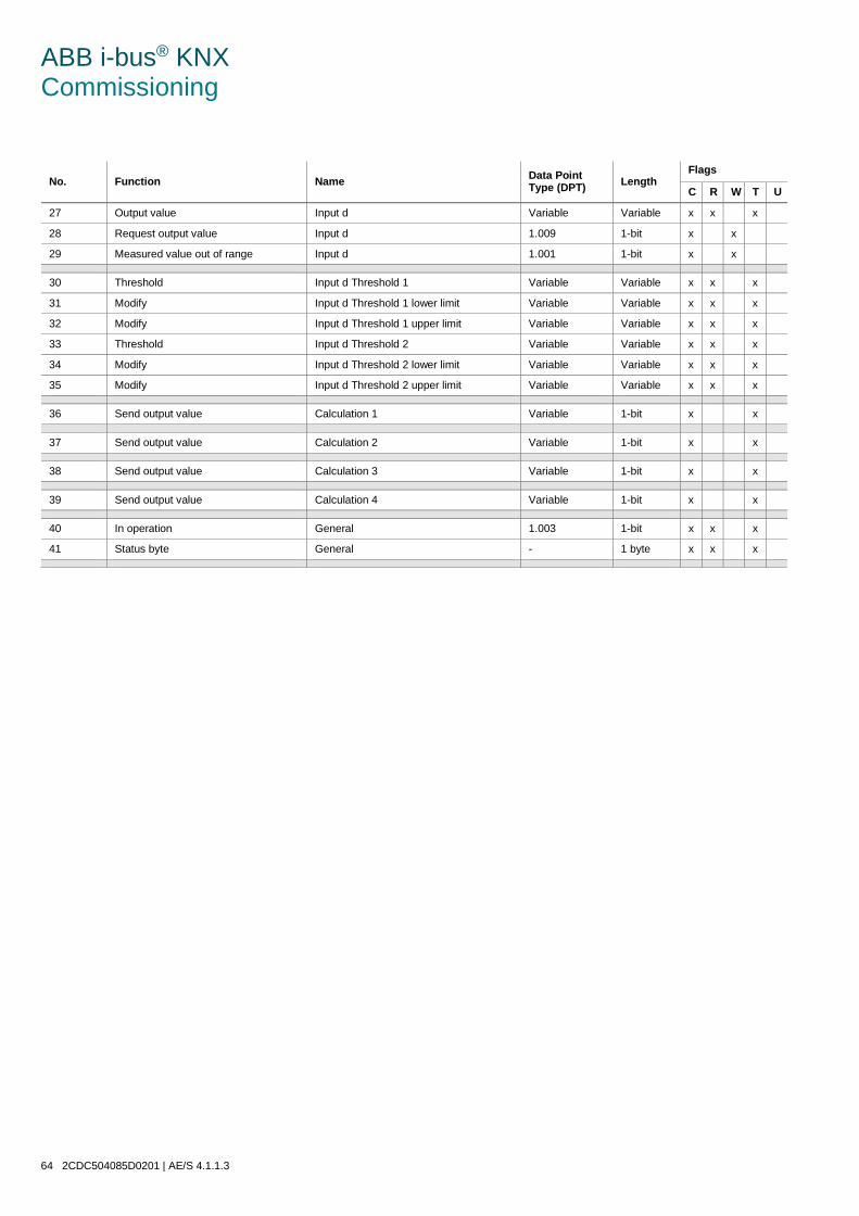
ABB i-bus® KNX Commissioning
No. Function Name Data Point Type (DPT) Length
Flags
C R W T U
27 Output value Input d Variable Variable x x x
28 Request output value Input d 1.009 1-bit x x
29 Measured value out of range Input d 1.001 1-bit x x
30 Threshold Input d Threshold 1 Variable Variable x x x
31 Modify Input d Threshold 1 lower limit Variable Variable x x x
32 Modify Input d Threshold 1 upper limit Variable Variable x x x
33 Threshold Input d Threshold 2 Variable Variable x x x
34 Modify Input d Threshold 2 lower limit Variable Variable x x x
35 Modify Input d Threshold 2 upper limit Variable Variable x x x
36 Send output value Calculation 1 Variable 1-bit x x
37 Send output value Calculation 2 Variable 1-bit x x
38 Send output value Calculation 3 Variable 1-bit x x
39 Send output value Calculation 4 Variable 1-bit x x
40 In operation General 1.003 1-bit x x x
41 Status byte General - 1 byte x x x
64 2CDC504085D0201 | AE/S 4.1.1.3

ABB i-bus® KNX Commissioning 3.3.2 Communication objects Input a
No. Function Object name Data type Flags
0 Output value Input a Variable DPT variable
C, R, T
This communication object is used to send the output value to the bus. The following values can be sent: 1-bit value [0/1] DPT 1.001 1-byte value [0...+255] DPT 5.010 1-byte value [-128...+127] DPT 6.010 2-byte value [0...+65,535] DPT 7.001 2-byte value [-32,768...+32,767] DPT 8.001 2 byte value (floating point) DPT 9.001 4-byte value (IEEE floating point) DPT 14.068 What is sent at an undershoot or overshoot of 10 %? Up to an overshoot of 10 % the measured value is shown and sent. This applies to both the upper and lower limits. Furthermore, the measured value continues to be sent as a Measured value +10 %. The following must be observed, particularly with the lower limit: This only applies if the lower limit is different from 0. If the lower limit is 0, it is not possible to determine an undershoot. 1 Request output value Input a 1-bit
DPT 1.009 C, W
This communication object appears if the output value On request is to be sent If a 1 is received at this communication object, the current output value is sent once from the communication object Output value – Input a.
AE/S 4.1.1.3 | 2CDC504085D0201 65

ABB i-bus® KNX Commissioning
2 Measured value out of range Input a 1-bit DPT 1.001
C, W
Telegram value: 1 = Measured value out of range 0 = Measured value in range
The communication object can be used to check the plausibility of the sensor, e.g. wire breakage at 1–10 V or at 4–20 mA. The check is carried out after each measurement.
Example
A wind sensor with a sensor signal of 4...20 mA and a measuring range of 0…40 m/s is connected to the Analogue Input. Output range is 16 mA (20...4 mA)
Upper measuring limit: The communication object Measured value outside range is sent when the upper measuring limit is exceeded by 5 %, i.e. 16.8 mA (16 mA + 5 %). Lower measuring limit: The communication object Measured value out of range is sent when the lower measuring limit is undershot by 5 %, i.e. 3.8 mA (4 mA - 5 %). When is the value of the communication object sent? Measured value out of range is sent if the measured value exceeds the lower or upper limit by more than 5 %. The following must be observed, particularly with the lower limit: This only applies if the lower limit is different from 0. If the lower limit is 0, it is not possible to determine an undershoot.
Behavior with PT100 or PT1000? The following applies with the calculation of the maximum and minimum output values with the PT100/1000: The lowest measurable resistance with the PT100 is about 80 ohms (with the PT1000 800 ohms) and corresponds to about -50 °C. The highest measurable resistance with the PT100 is about 157 ohms (with the PT1000 1,570 ohms) and corresponds to about +150 °C.
Important
The programmable feeder line resistance is subtracted from the measured resistance. Thereafter, a programmable temperature offset is added. Depending on the programming of the feeder line resistances and the temperature offset, different minimum and maximum values result. If the sensor goes open circuit, the highest possible positive temperature value in °C is sent. If the sensor goes short circuit, the lowest possible negative temperature value in °C is sent. The sent temperature values are dependent, for example, on the temperature sensor used, on line faults, ambient temperatures, etc.
Behavior with a floating contact? The communication object has no function with the selection.
66 2CDC504085D0201 | AE/S 4.1.1.3

ABB i-bus® KNX Commissioning
No. Function Object name Data type Flags 3 Threshold Input a Threshold 1 Variable
DPT variable C, R, T
As soon as the set threshold is exceeded or fallen below, it is possible to send the following values: 1-bit value [0/1] DPT 1.001 1-byte value [0...+255] DPT 5.010 The object value depends on the parameter Data type of threshold object (1-bit, 1-byte). The parameter can be found in the parameter window a: Threshold 1. 4…5 Modify Input a Threshold 1
lower limit Input a Threshold 1 upper limit
Variable DPT variable
C, R, T
The upper and lower limits of threshold 1 can be changed via the bus. The data type of these communication objects depends on the set data type of the communication object Output value – Input a.
Important
The lower limit should be selected to be lower than the upper limit.
6 See communication object 3 Input a Threshold 2 7…8 See communication objects 4 and 5 Input a Threshold 2
lower limit Input a Threshold 2 upper limit
3.3.3 Communication objects Input b, c and d
No. Function Object name Data type Flags
9…17 See communication objects 0...8 Input b 18…26 See communication objects 0...8 Input c 27…35 See communication objects 0...8 Input d
Note
With the 3-conductor connection the following applies: • Input a or c always measures the measuring resistor. • Input b or d always measures the cable resistance. When a 3-conductor connection is selected, inputs b and d are visible in the communication objects. If a group address is linked to these inputs, then the measured cable resistance is transmitted. It should be noted that the temperature value must be converted with the DPT 9.001, so that the resistance value remains intact.
AE/S 4.1.1.3 | 2CDC504085D0201 67

ABB i-bus® KNX Commissioning 3.3.4 Communication objects Calculation 1
No. Function Object name Data type Flags
36 Send output value Calculation 1 1-bit DPT variable
C, T
The result of calculation 1 is sent with this communication object. Depending on the calculation type which has been selected, the following values are sent: 1-bit value [0/1] DPT 1.001 1-byte value [0...+255] DPT 5.010 1-byte value [-128...+127] DPT 6.010 2-byte value [0...+65,535] DPT 7.001 2-byte value [-32,768...+32,767] DPT 8.001 2 byte value (floating point) DPT 9.001 4-byte value (IEEE floating point) DPT 14.068
Important
In order to guarantee full interoperability to other KNX devices, only a data type should be selected for the output which according to KONNEX is permissible for the calculated physical value!
3.3.5 Communication objects Calculation 2, 3, and 4
No. Function Object name Data type Flags
37 See communication object 36 Calculation 2 38 See communication object 36 Calculation 3 39 See communication object 36 Calculation 4
68 2CDC504085D0201 | AE/S 4.1.1.3

ABB i-bus® KNX Commissioning 3.3.6 Communication objects General
No. Function Object name Data type Flags
40 In operation General 1-bit DPT 1.003
C, R, T
This communication object appears if, in the Parameter window General, p. 23, Enable communication object "In operation", 1-bit has been selected and set to Value 0 or Value 1. A 0 or a 1 is sent cyclically on the bus depending on the setting.
41 Status byte General 1 byte DPT none
C, R, T
The status byte reflects the current state of the Analogue Input. Different states are indicated here, e.g. • Status Input a – Measured value out of range • Status Input a – Measured value out of range and self calibration Bit sequence: 76543210 Bit 7: Not assigned always 0 Bit 6: Mains voltage failure: 0: Mains available
1: Mains voltage failure, no measured values
Bit 5: Not assigned always 0 Bit 4: Status of internal calibration 0: Calibration completed
1: Calibration running
Bit 3: Status Input d Measured value out of range 0: In range
1: Out of range
Bit 2: Status Input c Measured value out of range 0: In range
1: Out of range
Bit 1: Status Input b Measured value out of range 0: In range
1: Out of range
Bit 0: Status Input a Measured value out of range 0: In range
1: Out of range
The value of the communication object is sent when a change occurs or can be read out via a Value Read command. The value of the communication object is sent automatically once after the device has started after the set send delay. For further information see: Value table of communication object Status byte – General
AE/S 4.1.1.3 | 2CDC504085D0201 69


ABB i-bus® KNX Planning and application 4 Planning and application
4.1 Description of the Threshold function
How does the threshold function work?
Settings • Communication object Threshold is set to a 1-bit value.
• An OFF telegram is sent with an undershoot of the threshold, and an ON telegram is sent with an overshoot of the threshold.
In the example diagram above, it can be seen that the measured value begins "somewhere", in this example with a 0 value. The communication object for Threshold 1 has the value 0 and is sent cyclically as per application settings.
As long as the measured value does not exceed the upper limit of threshold 1, the communication object Threshold will remain at value 0.
As soon as the measured value exceeds the upper limit of threshold 1, the communication object Threshold will change value to 1.
The communication object Threshold 1 will remain 1 until the measured value falls back below the lower limit of threshold 1.
AE/S 4.1.1.3 | 2CDC504085D0201 71


ABB i-bus® KNX Appendix A Appendix
A.1 Scope of delivery
The device is supplied together with the following components. Please check the items received using the following list:
• 1 (one) AE/S 4.1.1.3 Analogue Input, 4-fold, MDRC
• 1 (one) set of installation and operating instructions
• 1 (one) bus connection terminal (red/black)
AE/S 4.1.1.3 | 2CDC504085D0201 73

ABB i-bus® KNX Appendix A.2 Value table of communication object Status byte – General
Bit No. 7 6 5 4 3 2 1 0 Bit
No. 7 6 5 4 3 2 1 0 Bit No. 7 6 5 4 3 2 1 0
8-bi
t val
ue
Hex
adec
imal
Not
ass
igne
d
Mai
ns v
olta
ge
failu
re
Not
ass
igne
d
Stat
us o
f int
erna
l ca
libra
tion
Stat
us In
put d
Stat
us In
put c
Stat
us In
put b
Stat
us In
put a
8-bi
t val
ue
Hex
adec
imal
Not
ass
igne
d
Mai
ns v
olta
ge
failu
re
Not
ass
igne
d
Stat
us o
f int
erna
l ca
libra
tion
Stat
us In
put d
Stat
us In
put c
Stat
us In
put b
Stat
us In
put a
8-bi
t val
ue
Hex
adec
imal
Not
ass
igne
d
Mai
ns v
olta
ge
failu
re
Not
ass
igne
d
Stat
us o
f int
erna
l ca
libra
tion
Stat
us In
put d
Stat
us In
put c
Stat
us In
put b
Stat
us In
put a
0 00 86 56 172 AC 1 01 87 57 173 AD 2 02 88 58 174 AE 3 03 89 59 175 AF 4 04 90 5A 176 B0 5 05 91 5B 177 B1 6 06 92 5C 178 B2 7 07 93 5D 179 B3 8 08 94 5E 180 B4 9 09 95 5F 181 B5 10 0A 96 60 182 B6 11 0B 97 61 183 B7 12 0C 98 62 184 B8 13 0D 99 63 185 B9 14 0E 100 64 186 BA 15 0F 101 65 187 BB 16 10 102 66 188 BC 17 11 103 67 189 BD 18 12 104 68 190 BE 19 13 105 69 191 BF 20 14 106 6A 192 C0 21 15 107 6B 193 C1 22 16 108 6C 194 C2 23 17 109 6D 195 C3 24 18 110 6E 196 C4 25 19 111 6F 197 C5 26 1A 112 70 198 C6 27 1B 113 71 199 C7 28 1C 114 72 200 C8 29 1D 115 73 201 C9 30 1E 116 74 202 CA 31 1F 117 75 203 CB 32 20 118 76 204 CC 33 21 119 77 205 CD 34 22 120 78 206 CE 35 23 121 79 207 CF 36 24 122 7A 208 D0 37 25 123 7B 209 D1 38 26 124 7C 210 D2 39 27 125 7D 211 D3 40 28 126 7E 212 D4 41 29 127 7F 213 D5 42 2A 128 80 214 D6 43 2B 129 81 215 D7 44 2C 130 82 216 D8 45 2D 131 83 217 D9 46 2E 132 84 218 DA 47 2F 133 85 219 DB 48 30 134 86 220 DC 49 31 135 87 221 DD 50 32 136 88 222 DE 51 33 137 89 223 DF 52 34 138 8A 224 E0 53 35 139 8B 225 E1 54 36 140 8C 226 E2 55 37 141 8D 227 E3 56 38 142 8E 228 E4 57 39 143 8F 229 E5 58 3A 144 90 230 E6 59 3B 145 91 231 E7 60 3C 146 92 232 E8 61 3D 147 93 233 E9 62 3E 148 94 234 EA 63 3F 149 95 235 EB 64 40 150 96 236 EC 65 41 151 97 237 ED 66 42 152 98 238 EE 67 43 153 99 239 EF 68 44 154 9A 240 F0 69 45 155 9B 241 F1 70 46 156 9C 242 F2 71 47 157 9D 243 F3 72 48 158 9E 244 F4 73 49 159 9F 245 F5 74 4A 160 A0 246 F6 75 4B 161 A1 247 F7 76 4C 162 A2 248 F8 77 4D 163 A3 249 F9 78 4E 164 A4 250 FA 79 4F 165 A5 251 FB 80 50 166 A6 252 FC 81 51 167 A7 253 FD 82 52 168 A8 254 FE 83 53 169 A9 255 FF 84 54 170 AA 85 55 171 AB
Empty = Value 0 = Value 1, applicable
74 2CDC504085D0201 | AE/S 4.1.1.3

ABB i-bus® KNX Appendix A.3 Conversion between °C and °F
No.: °C °F 1 -50 -58 2 -40 -40 3 -30 -22 4 -17.8 0 5 -20 -4 6 -10 +14 7 0 +32 8 +10 +50 9 +20 +68 10 +30 +86 11 +50 +122 12 +60 +140 13 +70 +158 14 +80 +176 15 +90 +194 16 +100 +212 17 +110 +230 18 +120 +248 19 +130 +266 20 +140 +284 21 +150 +302
Conversion formula Celsius to Fahrenheit
Temperature in °F = ((T °Celsius x 9) / 5) + 32
Fahrenheit to Celsius
Temperature in °C = (T °Fahrenheit - 32) x 5 / 9
AE/S 4.1.1.3 | 2CDC504085D0201 75

ABB i-bus® KNX Appendix A.4 Order details
Short description Designation Order No. bbn 40 16779 EAN
Weight 1 pc. [kg]
Packaging [pcs.]
AE/S 4.1.1.3 Analogue Input, 4-fold, MDRC 2CDG110190R0011 929295 0.27 1
76 2CDC504085D0201 | AE/S 4.1.1.3

Contact
ABB STOTZ-KONTAKT GmbH Eppelheimer Strasse 82 69123 Heidelberg, Germany Telephone: +49 (0)6221 701 607 +49 (0)6221 701 434 Fax: +49 (0)6221 701 724 E-mail: [email protected] Further information and local contacts: www.abb.com/knx
Note: We reserve the right to make technical changes or modify the contents of this document without prior notice. The agreed properties are definitive for any orders placed. ABB AG does not accept any responsibility whatsoever for potential errors or possible lack of information in this document. We reserve all rights in this document and in the subject matter and illustrations contained therein. Reproduction, transfer to third parties or processing of the content – including sections thereof – is not permitted without prior expressed written permission from ABB AG. Copyright © 2015 ABB All rights reserved
Pu
blic
atio
n nu
mbe
r 2C
DC
5040
85D
0201
(04.
15)