abb control technologies abb screenmaster paperless recorders versatile recording...
TRANSCRIPT

ABB ScreenMaster paperless recordersVersatile recording anywhere
ABB Control Technologies
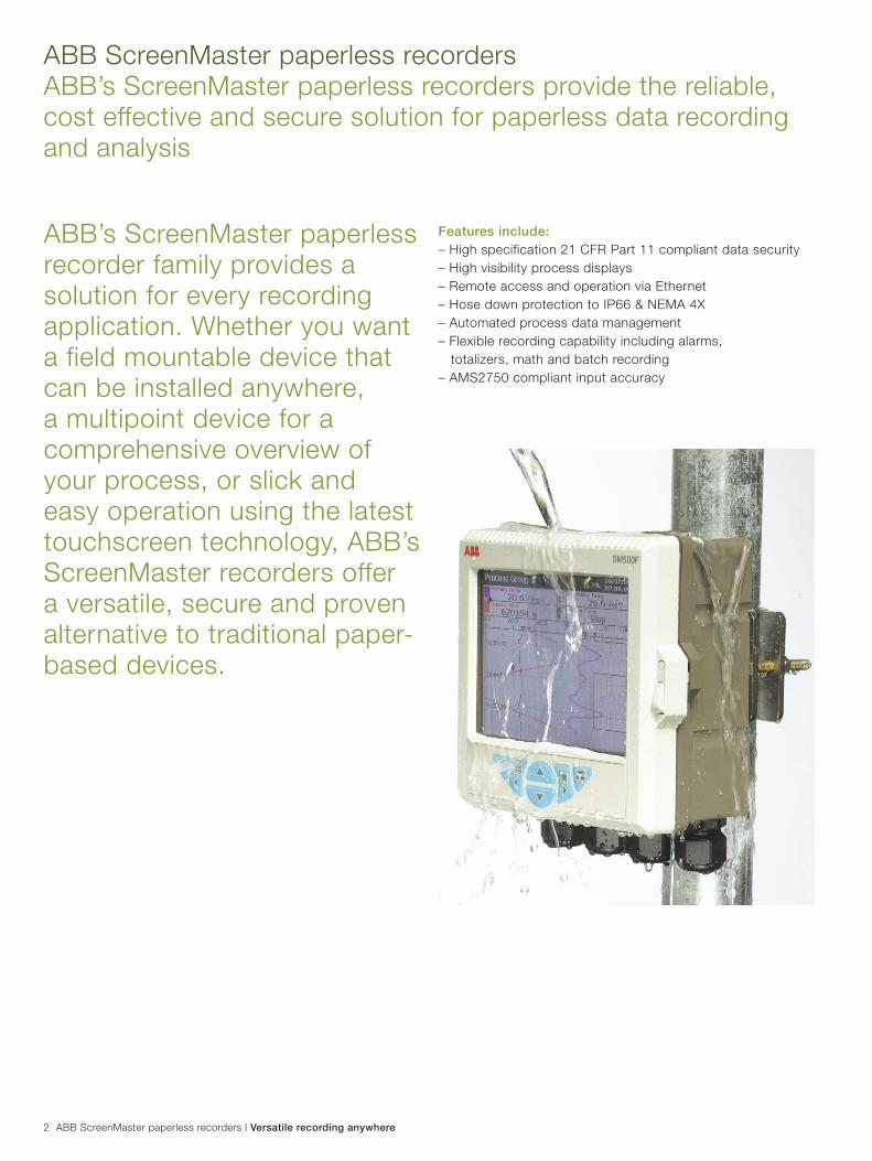
ABB ScreenMaster paperless recorders ABB’s ScreenMaster paperless recorders provide the reliable, cost effective and secure solution for paperless data recording and analysis
2 ABB ScreenMaster paperless recorders l Versatile recording anywhere
ABB’s ScreenMaster paperless recorder family provides a solution for every recording application. Whether you want a field mountable device that can be installed anywhere, a multipoint device for a comprehensive overview of your process, or slick and easy operation using the latest touchscreen technology, ABB’s ScreenMaster recorders offer a versatile, secure and proven alternative to traditional paper-based devices.
Features include: – High specification 21 CFR Part 11 compliant data security – High visibility process displays – Remote access and operation via Ethernet – Hose down protection to IP66 & NEMA 4X – Automated process data management – Flexible recording capability including alarms, totalizers, math and batch recording– AMS2750 compliant input accuracy

ABB ScreenMaster paperless recorders l Versatile recording anywhere 3
Simple, tough and versatile, the ScreenMaster range gives you a comprehensive solution for your data recording needs
Powerful yet simpleSetting up and operating a ScreenMaster recorder is easy. A simple menu-based interface takes the hard work out of configuration and makes it easy to find and view your process data, with multiple display formats offering a wide choice of viewing options.
Suitable for even the most arduous environmentsProtected to NEMA 4X and IP66 as standard, ScreenMaster recorders can be installed next to the process in even the wettest or grimiest conditions, giving you local access to your information at your fingertips.

Secure, precise, reliable recording
Flexible recording capabilityA wide range of features give ScreenMaster recorders the flexibility to meet the requirements of almost any recording application.
Flow recordingFlow totalizers enable instantaneous flow rates to be totalized and recorded. An automatic reset capability enables reports of daily, weekly, monthly flow volumes to be generated and alarms to be raised if predefined flow limits for a given time period are exceeded.
Powerful mathsMathematical functions such as averages and deviations can be calculated using ScreenMaster’s math and logic option. Results of math calculations can be displayed, recorded and used to drive alarms and totalizers.
Batch recordingFor batch processes, ScreenMaster’s batch recording option allows data including batch numbers and product type
information to be recorded alongside process data. With ABB’s DataManager Pro software, collected batch records can be rapidly displayed by searching for their batch number or batches with common attributes identified.
The highest levels of data protectionEvery model in the ScreenMaster range incorporates the highest levels of protection against the accidental loss of valuable process data.
Multiple users can be configured, each with individual user name, password and access rights. A comprehensive audit log records configuration changes, calibration changes, system events and many other items key to data security. Where applicable, all entries are detailed with operator identification. Operators can securely annotate the chart with comments and signatures.
ScreenMaster’s standard complement of security features mean that it is also fully compliant with the requirements of 21 CFR Part 11.
4 ABB ScreenMaster paperless recorders l Versatile recording anywhere
Ethernet communicationsIt is very simple to connect a ScreenMaster recorder to an existing plant network via Ethernet communications. Once connected, archived data and email facilities become instantly available. Using a modem router or GSM technology, the ScreenMaster’s labour-saving Ethernet features can still be used even when a recorder is in a remote location.
Remote process monitoringRemote access to a ScreenMaster is possible via the use of any standard web browser. Detailed real-time information is available for current alarm and totalizer conditions, memory card status and many other key process details. For an on-line demonstration of this feature enter http://217.46.239.73 in to the address bar of your web browser.
Email notificationKeep up to date with the latest process alarms or critical process events with email notifications which can be automatically sent to your PC or smartphone. The same technology can also be used to provide routine performance updates, giving you even greater power over your process.
Real-time data communicationVia the use of MODBUS TCP or RTU protocol, a ScreenMaster recorder can communicate the process values being monitored to a DCS, SCADA, PLC or other similar system. Alternatively, data values can be communicated to a ScreenMaster for display to the operator and secure logging of the data.
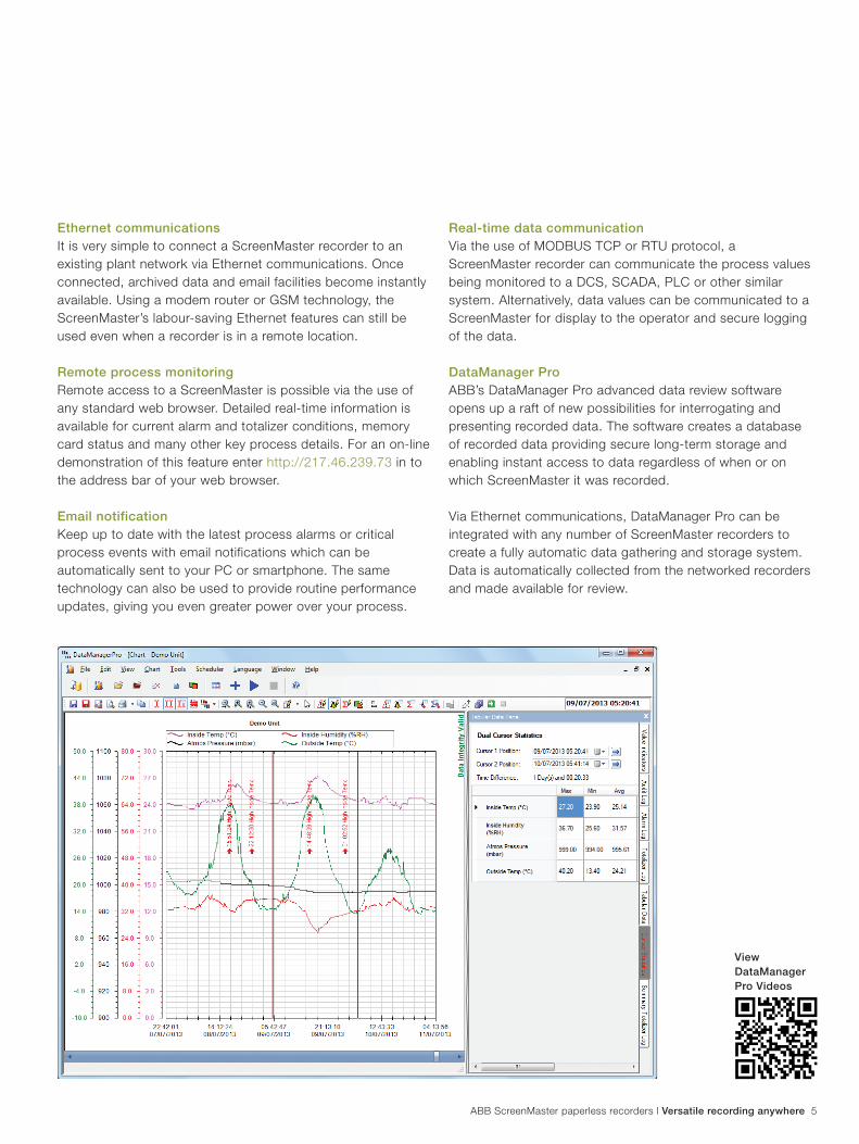
DataManager ProABB’s DataManager Pro advanced data review software opens up a raft of new possibilities for interrogating and presenting recorded data. The software creates a database of recorded data providing secure long-term storage and enabling instant access to data regardless of when or on which ScreenMaster it was recorded.
Via Ethernet communications, DataManager Pro can be integrated with any number of ScreenMaster recorders to create a fully automatic data gathering and storage system. Data is automatically collected from the networked recorders and made available for review.
ABB ScreenMaster paperless recorders l Versatile recording anywhere 5
View DataManagerPro Videos
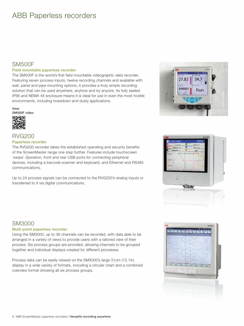
ABB Paperless recorders
SM500FField mountable paperless recorderThe SM500F is the world’s first field mountable videographic data recorder. Featuring seven process inputs, twelve recording channels and available with wall, panel and pipe mounting options, it provides a truly simple recording solution that can be used anywhere, anyhow and by anyone. Its fully sealed IP66 and NEMA 4X enclosure means it is ideal for use in even the most hostile environments, including hosedown and dusty applications.
RVG200Paperless recorder The RVG200 recorder takes the established operating and security benefits of the ScreenMaster range one step further. Features include touchscreen ‘swipe’ operation, front and rear USB ports for connecting peripheral devices, including a barcode scanner and keyboard, and Ethernet and RS485 communications.
Up to 24 process signals can be connected to the RVG200’s analog inputs or transferred to it via digital communications.
SM3000Multi-point paperless recorderUsing the SM3000, up to 36 channels can be recorded, with data able to be arranged in a variety of views to provide users with a tailored view of their process. Six process groups are provided, allowing channels to be grouped together and individual displays created for different processes.
Process data can be easily viewed on the SM3000’s large 31cm (12.1in) display in a wide variety of formats, including a circular chart and a combined overview format showing all six process groups.
6 ABB ScreenMaster paperless recorders l Versatile recording anywhere
ViewSM500F video
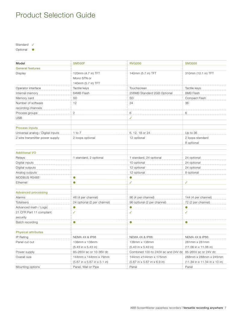
Product Selection Guide
Model SM500F RVG200 SM3000
General features
Display 120mm (4.7 in) TFT 140mm (5.7 in) TFT 310mm (12.1 in) TFT
Mono STN or
140mm (5.7 in) TFT
Operator interface Tactile keys Touchscreen Tactile keys
Internal memory 64MB Flash 256MB Standard 2GB Optional 8MB Flash
Memory card SD SD Compact Flash
Number of software 12 24 36
recording channels
Process groups 2 6 6
USB 3
Process inputs
Universal analog / Digital inputs 1 to 7 6, 12, 18 or 24 Up to 36
2 wire transmitter power supply 2 loops optional 12 optional 2 loops standard
8 optional
Additional I/O
Relays 1 standard, 2 optional 1 standard, 24 optional 24 optional
Digital inputs 10 optional 24 optional
Digital outputs 12 optional 24 optional
Analog outputs 12 optional 8 optional
MODBUS RS485 l l
Ethernet l 3 3
Advanced processing
Alarms 48 (4 per channel) 96 (4 per channel) 144 (4 per channel)
Totalisers 24 optional (2 per channel) 96 optional (2 per channel) 72 (2 per channel)
Advanced math / Logic l l l
21 CFR Part 11 compliant 3 3 3
security
Batch recording l l l
Physical attributes
IP Rating NEMA 4X & IP66 NEMA 4X & IP66 NEMA 4X & IP66
Panel cut out 138mm x 138mm 138mm x 138mm 281mm x 281mm
(5.43 in x 5.43 in) (5.43 in x 5.43 in) (11.06 in x 11.06 in)
Power supply 85-265V ac or 10-36V dc Combined 100-to 240V ac and 24V dc 85-265V ac or 24V dc
Overall size 144mm x 144mm x 79mm 144mm x144mm x 175mm 288mm x 288mm x 245mm
(5.67 in x 5.67 in x 3.1 in) (5.67 in x 5.67 in x 6.9 in) (11.34 in x 11.34 in x 10 in)
Mounting options Panel, Wall or Pipe Panel Panel
Standard 3
Optional l
ABB ScreenMaster paperless recorders l Versatile recording anywhere 7

To find your local ABB contact visit:www.abb.com/contacts
For more product information visit:www.abb.com/recorders
PB
/SM
SE
RIE
S-E
N R
ev. ENotes:
We reserve the right to make technical changes or modify the contents of this document without prior notice. With regard to purchase orders, the agreed particulars shall prevail. ABB does not accept any responsibility whatsoever for potential errors or possible lack of information in this document.
We reserve all rights in this document and in the subject matter and illustrations contained therein. Any reproduction, disclosure to third parties or utilization of its contents – in whole or in parts – is forbidden without prior written consent of ABB.
Copyright© 2013 ABB
All rights reserved
Contact us
www.abb.com/recorders

Measurement made easy
Data sheet DS/RVG200–EN Rev. C
ScreenMaster RVG200Paperless recorder
Secure process data at your fingertips
High security data recording— encrypted data storage compliant to 21 CFR Part 11— up to 2 GB of internal memory
Simple, intuitive operation— touchscreen operation and configuration— USB ports for keyboard and barcode scanner
Easy network integration— standard Ethernet communications provide remote data
access, process supervision and easy integration to control systems
— RS485 MODBUS RTU master and slave
Complete data recording solution— automatic data collection via Ethernet combined with
powerful data analysis using DataManager Pro software
Built to survive— IP66 and NEMA 4X environmental protection
Scalable high specification I/O— high accuracy and stability compliant to AMS 2750 E— recording of up to 24 channels— optional relays, mA outputs and Tx PSU
Advanced functionality— math and logic— batch recording— flow totalization

ScreenMaster RVG200Paperless recorder
2 DS/RVG200–EN Rev. C | ScreenMaster RVG200 | Paperless recorder
Overview
The ScreenMaster RVG200 is a secure, easy-to-use paperless recorder. Up to 24 process signals can be connected directly to the RVG200's analog inputs or transferred to it via digital communications. All process data, including alarm conditions, math calculation results and totalizer values, are displayed clearly to the operator and archived securely in an encrypted format for review using the accompanying DataManager Pro PC software.A touch screen featuring swipe gesture control provides fast and intuitive operation. USB ports further simplify operation by enabling peripherals (for example, a keyboard, mouse or barcode scanner) to be attached.The RVG200's standard Ethernet communications and inbuilt web server enable:— easy integration to an existing network— automatic data collection— remote process supervision
6, 12, 18 or 24 universal inputs— Thermocouple— RTD— mA— mV— Resistance— Voltage— Digital
1 relay output
6, 12, 18 or 24 relay outputs
6 or 12 hybrid outputs— 24 V transmitter power supply— mA retransmission— 24 V digital output
5 or 10 digital inputs
Ethernet communications— Web server— FTP— Email— MODBUS TCP master and slave
RS485 communications— MODBUS RTU master and slave
24 software recording channels— 6 process groups— 96 process alarms— 4 real-time alarms— 2 custom linearizers
2 USB ports
SD memory card
256 MB internal memory
2 GB internal memory
Batch recording
48 totalizers / timers
Math and logic— 24 math blocks— 24 logic equations
Universal power supply— 100 to 240 V AC, 50 / 60 Hz— 24 V DC
Key: Standard Optional
Lockable media door
Tamper-evident seals
ScreenMaster RVG200 | Paperless recorder | DS/RVG200–EN Rev. C 3
1011100101101011
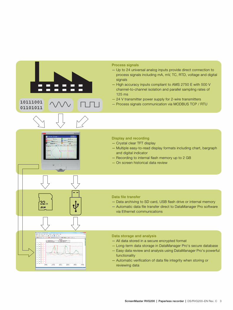
Process signals— Up to 24 universal analog inputs provide direct connection to
process signals including mA, mV, TC, RTD, voltage and digital signals
— High accuracy inputs compliant to AMS 2750 E with 500 V channel-to-channel isolation and parallel sampling rates of 125 ms
— 24 V transmitter power supply for 2-wire transmitters— Process signals communication via MODBUS TCP / RTU
Display and recording— Crystal clear TFT display— Multiple easy-to-read display formats including chart, bargraph
and digital indicator— Recording to internal flash memory up to 2 GB— On screen historical data review
Data file transfer— Data archiving to SD card, USB flash drive or internal memory— Automatic data file transfer direct to DataManager Pro software
via Ethernet communications
Data storage and analysis— All data stored in a secure encrypted format— Long-term data storage in DataManager Pro's secure database— Easy data review and analysis using DataManager Pro's powerful
functionality— Automatic verification of data file integrity when storing or
reviewing data

ScreenMaster RVG200Paperless recorder
4 DS/RVG200–EN Rev. C | ScreenMaster RVG200 | Paperless recorder
Display examples
To display process information clearly, the RVG200 features 6 configurable process groups. This enables signals from one process to be grouped by type or enables the RVG200 to monitor up to 6 separate processes. Each process group has its own set of displays including a chart, bargraph and digital indicator. Additionally, an overview display simultaneously shows all process signals being recorded.
Easy operation
The RVG200's responsive touchscreen makes operation quick and simple. The intuitively structured operation and configuration menus can be navigated quickly via an icon-based system or the process groups and displays controlled via on-screen swipe gestures.
Fig. 1: Chart, indicator, bargraph, and overview displays
Fig. 2: Navigation using on-screen swipe gestures

ScreenMaster RVG200 | Paperless recorder | DS/RVG200–EN Rev. C 5
Ethernet integration
Easy integration
— 100 Mb Ethernet fitted as standard— Static or automatic IP address
configuration via DHCP
DataManager Pro software
— Automatic scheduled data file collection from multiple recorders
— Time synchronization
Web server
— Remote supervision of process and recorder— Uses a standard web browser or smart phone –
no special software required— Acknowledge alarms and operate totalizers remotely— Load new configurations remotely
— Process alarm or critical process condition notification by email
— Scheduled process status reports by email
MODBUS TCP
— Master (client) and slave (server) capability
— Communication of real-time data to / from recorder

ScreenMaster RVG200Paperless recorder
6 DS/RVG200–EN Rev. C | ScreenMaster RVG200 | Paperless recorder
Historical logsThree historical logs are kept providing detailed alarm, totalizer and audit history.
Alarm event log — a complete history of all alarm occurrences including state
changes, acknowledgements and operator messages.
Totalizer log — a convenient summary of totalizer readings including daily,
weekly and monthly values.
Audit log — time, date and ID stamped system data including
notification of configuration changes, calibration adjustments and operator actions. The audit log provides detailed evidence of the recorder's integrity and the validity of recorded data.
Math and logicMath and logic capabilities are available as an option, providing powerful problem solving capability. Bracket and nesting capability enable complex equations to be created, the results of which can be displayed on screen, trended and logged to the memory card. Functionality includes:— Standard mathematical functions (for example, addition,
subtraction, multiplication and division) enable signals to be compared and the comparison values recorded or averages of groups of signals to be calculated.
— Switch and high / low selection functions provide sensor redundancy capability with failure-driven automatic switching between sensors.
— Rolling and real-time average functions can be applied to noisy or erratic process signals proving clearer representation of process trends.
Batch recordingThe batch recording option enables simple recording and reviewing of batch processes. When a batch is started it is tagged with a unique batch number, operator identification and 3 user-definable description fields. All information can be entered using the on-screen keyboard, a USB keyboard or a barcode scanner. RVG200 can accommodate multiple batches within single- or multiple-process groups simultaneously.Using DataManager Pro, batches can be recalled for review simply and quickly using the unique batch number or descriptive information entered at the time of its recording. Additional functionality provides the ability to search and sort batch records for an entire production facility in many ways; including by product type, operator and time and date of processing.
Fig. 3: Batch recording configuration dialog

ScreenMaster RVG200 | Paperless recorder | DS/RVG200–EN Rev. C 7
DataManager Pro off-line review and analysis softwareThe RVG200 combined with ABB's DataManager Pro software provides a complete data recording, analysis and long-term storage solution.All process data and historical log archive files recorded by the RVG200 are compatible with DataManager Pro.
Features include:— Database management of data files ensures simple, secure,
long-term storage and instant retrieval of historical data.— The graphing capabilities provide powerful interrogation of
process data.— Validity checking of all data files during the storage and
retrieval process ensures maximum data integrity.— Automatic data file collection via Ethernet communications
from multiple ScreenMaster recorders provides maintenance-free data file collection.
For further information on the capabilities of DataManager Pro software, refer to data sheet DS/RDM500-EN.
21 CFR part 11 compliance and GAMP validation packageWith its comprehensive audit trail, secure archiving format and extensive physical and configuration security features, the ScreenMaster RVG200 is ideally suited to applications where compliance with 21CFR part 11 (the FDA's regulations regarding electronic record keeping) is required. For further information refer to INF13/147.A template for validating the RVG200 paperless recorder is available. Following GAMP 5 (a risk-based approach to compliant GxP computerized systems), the template is designed to make the validation process as simple as possible and provides an IQ and OQ that is completed at the customer site, before and after installation. Once completed, the template is then packaged together with other documentation relating to the system as a whole, ready to be presented to the governing regulatory body for inspection.
Fig. 4: DM Pro screen shot
ScreenMaster RVG200Paperless recorder
8 DS/RVG200–EN Rev. C | ScreenMaster RVG200 | Paperless recorder
Example applications / industries
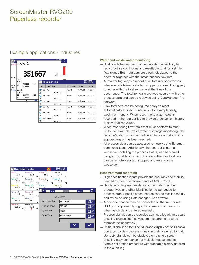
Water and waste water monitoring— Dual flow totalizers per channel provide the flexibility to
record both a continuous and resettable total for a single flow signal. Both totalizers are clearly displayed to the operator together with the instantaneous flow rate.
— A totalizer log keeps a record of all totalizer occurrences; whenever a totalizer is started, stopped or reset it is logged; together with the totalizer value at the time of the occurrence. The totalizer log is archived securely with other process data and can be reviewed using DataManager Pro software.
— Flow totalizers can be configured easily to reset automatically at specific intervals – for example, daily, weekly or monthly. When reset, the totalizer value is recorded in the totalizer log to provide a convenient history of flow totalizer values.
— When monitoring flow totals that must conform to strict limits, (for example, waste water discharge monitoring), the recorder's alarms can be configured to warn that a limit is approaching or has been reached.
— All process data can be accessed remotely using Ethernet communications. Additionally, the recorder's internal webserver, detailing the process status, can be viewed using a PC, tablet or smart phone and the flow totalizers can be remotely started, stopped and reset via the webserver.
Heat treatment recording— High specification inputs provide the accuracy and stability
needed to meet the requirements of AMS 2750 E.— Batch recording enables data such as batch number,
product type and other identification to be tagged to process data. Specific batch records can be recalled rapidly and reviewed using DataManager Pro software.
— A barcode scanner can be connected to the front or rear USB port to prevent typographical errors that can occur when batch data is entered manually.
— Process signals can be recorded against a logarithmic scale enabling signals such as vacuum measurements to be represented accurately.
— Chart, digital indicator and bargraph display options enable operators to view process signals in their preferred format. Up to 24 signals can be displayed on a single screen enabling easy comparison of multiple measurements.
— Simple calibration procedure with traceable history detailed in the audit log.
ScreenMaster RVG200 | Paperless recorder | DS/RVG200–EN Rev. C 9
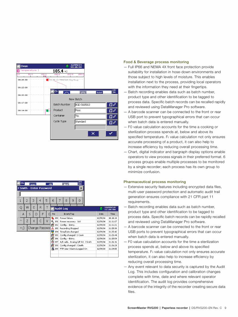
Food & Beverage process monitoring— Full IP66 and NEMA 4X front face protection provide
suitability for installation in hose-down environments and those subject to high levels of moisture. This enables installation next to the process, providing local operators with the information they need at their fingertips.
— Batch recording enables data such as batch number, product type and other identification to be tagged to process data. Specific batch records can be recalled rapidly and reviewed using DataManager Pro software.
— A barcode scanner can be connected to the front or rear USB port to prevent typographical errors that can occur when batch data is entered manually.
— F0 value calculation accounts for the time a cooking or sterilization process spends at, below and above its specified temperature. F0 value calculation not only ensures accurate processing of a product, it can also help to increase efficiency by reducing overall processing time.
— Chart, digital indicator and bargraph display options enable operators to view process signals in their preferred format. 6 process groups enable multiple processes to be monitored by a single recorder; each process has its own group to minimize confusion.
Pharmaceutical process monitoring— Extensive security features including encrypted data files,
multi-user password protection and automatic audit trail generation ensures compliance with 21 CFR part 11 requirements.
— Batch recording enables data such as batch number, product type and other identification to be tagged to process data. Specific batch records can be rapidly recalled and reviewed using DataManager Pro software.
— A barcode scanner can be connected to the front or rear USB ports to prevent typographical errors that can occur when batch data is entered manually.
— F0 value calculation accounts for the time a sterilization process spends at, below and above its specified temperature. F0 value calculation not only ensures accurate sterilization, it can also help to increase efficiency by reducing overall processing time.
— Any event relevant to data security is captured by the Audit Log. This includes configuration and calibration changes complete with time, date and where relevant operator identification. The audit log provides comprehensive evidence of the integrity of the recorder creating secure data files.

ScreenMaster RVG200Paperless recorder
10 DS/RVG200–EN Rev. C | ScreenMaster RVG200 | Paperless recorder
Technical specification
Operation and configurationConfiguration— Via resistive touch screen or PC Configuration— Multiple configuration files can be stored in internal memory
(up to 16 files) or external memory (SD card, USB flash drive)
Display— Color, TFT, liquid crystal display (LCD)
with LED backlight and brightness adjustment— 144 mm (5.7 in.) diagonal display area,
76800 pixel (1/4 VGA) display *Language English, German, French, Italian, Spanish, ChineseChart screen intervalsSelectable from 18 seconds to 7 daysChart divisionsProgrammable for up to 10 major and 10 minor divisionsChart annotationAlarm, batch, electronic signatures and operator messages may be annotated on the chart Real time clockAccuracy:— ±5 ppm (±0.43 seconds per day)Back-up battery:— Battery low warning— Provides 3 years support for unpowered condition— 10 year shelf-life
* A small percentage of the display pixels may be either constantly active or inactive. Maximum percentage of inoperative pixels < 0.01 %
SecurityPhysical— Lockable media door— Front and rear tamper-evident sealsConfiguration securityPassword protection:— Access to configuration is enabled only after the user has
entered a passwordInternal switch protection:— Access to configuration is enabled only after a hardware
switch has been set. This switch is situated behind a tamper-evident seal
Logging securityConfiguration:— Can be configured for password protection or free access to
logging levelBasic type security4 individual users with unique user name and passwordsAdvanced type securityNumber of users:— Up to 40User names*:— Up to 20 charactersAccess privileges:— Logging access – Yes / No— Configuration access – none / load file only / limited / fullPasswords:— Up to 20 characters— A minimum required password length of 4 to 20 characters
can be configured and a password expiry time can be applied to eliminate password ageing
Password failure limit:— Configurable for 1 to 10 consecutive occasions or 'infinite'— A user is deactivated if a wrong password is entered
repeatedlyDeactivation of inactive users:— Can be disabled or configured for 7, 14, 30, 60, 90, 180 or
360 days of inactivity— Users are deactivated (by removal of access privileges) after
a period of inactivity
* User names are unique (names cannot be repeated)

ScreenMaster RVG200 | Paperless recorder | DS/RVG200–EN Rev. C 11
Operator views
Standard functionality
Operator messagesNumber24TriggerVia front panel or digital signalsRecording in alarm / event logCan be enabled or disabled on configuration
Secure chart signaturesRecorded in the alarm / event log, complete with operator identification
Process alarmsNumber96 (4 per recording channel)TypesHigh / low:— Process— Latch— AnnunciatorRate:— Fast / slowTag20-character tag for each alarmHysteresisProgrammable value and time hysteresis (1 to 9999 seconds)Alarm enableAllows alarm to be enabled / disabled via a digital inputAlarm log enableRecording of alarm state changes in the alarm / event log can be enabled / disabled for each alarmAcknowledgementVia front panel or digital signals
Real-time alarmsNumber4ProgrammableDay of the week, 1st of month, start and duration times
Custom linearizationNumber2Number of breakpoints20 per linearizer
Views available
Contents Chart Bargraph Digital
indicator
Instantaneous values / states
Units of measure
Channel tags
Alarm status
Alarm trip markers —
Max. / Min. markers —
Analog bargraphs —
Totalizer values & units of measure — — *
Totalizer tags — — *
Maximum, minimum and average
batch values
— — *
Graphical view of historical data — —
* If Totalizer option is fitted and selected
ScreenMaster RVG200Paperless recorder
12 DS/RVG200–EN Rev. C | ScreenMaster RVG200 | Paperless recorder
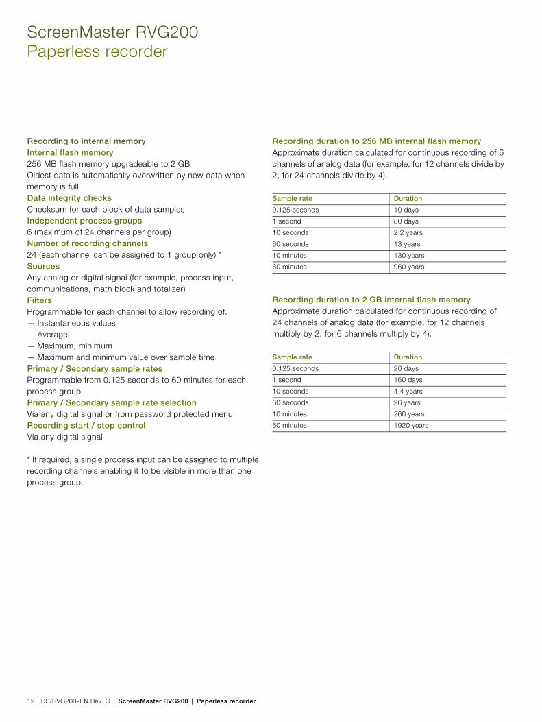
Recording to internal memoryInternal flash memory256 MB flash memory upgradeable to 2 GBOldest data is automatically overwritten by new data when memory is fullData integrity checksChecksum for each block of data samplesIndependent process groups6 (maximum of 24 channels per group)Number of recording channels24 (each channel can be assigned to 1 group only) *SourcesAny analog or digital signal (for example, process input, communications, math block and totalizer)FiltersProgrammable for each channel to allow recording of:— Instantaneous values— Average— Maximum, minimum— Maximum and minimum value over sample timePrimary / Secondary sample ratesProgrammable from 0.125 seconds to 60 minutes for each process groupPrimary / Secondary sample rate selectionVia any digital signal or from password protected menuRecording start / stop controlVia any digital signal
* If required, a single process input can be assigned to multiple recording channels enabling it to be visible in more than one process group.
Recording duration to 256 MB internal flash memoryApproximate duration calculated for continuous recording of 6 channels of analog data (for example, for 12 channels divide by 2, for 24 channels divide by 4).
Recording duration to 2 GB internal flash memoryApproximate duration calculated for continuous recording of 24 channels of analog data (for example, for 12 channels multiply by 2, for 6 channels multiply by 4).
Sample rate Duration
0.125 seconds 10 days
1 second 80 days
10 seconds 2.2 years
60 seconds 13 years
10 minutes 130 years
60 minutes 960 years
Sample rate Duration
0.125 seconds 20 days
1 second 160 days
10 seconds 4.4 years
60 seconds 26 years
10 minutes 260 years
60 minutes 1920 years
ScreenMaster RVG200 | Paperless recorder | DS/RVG200–EN Rev. C 13
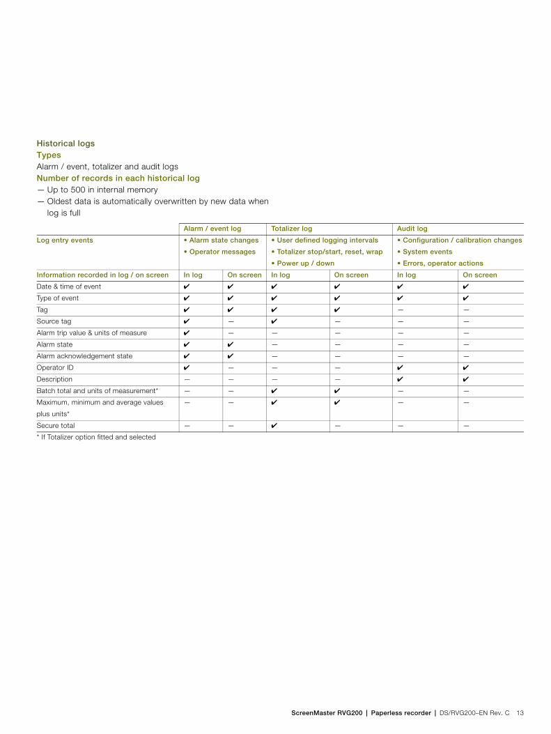
Historical logsTypesAlarm / event, totalizer and audit logsNumber of records in each historical log— Up to 500 in internal memory— Oldest data is automatically overwritten by new data when
log is full
Alarm / event log Totalizer log Audit log
Log entry events • Alarm state changes
• Operator messages
• User defined logging intervals
• Totalizer stop/start, reset, wrap
• Power up / down
• Configuration / calibration changes
• System events
• Errors, operator actions
Information recorded in log / on screen In log On screen In log On screen In log On screen
Date & time of event
Type of event
Tag — —
Source tag — — — —
Alarm trip value & units of measure — — — — —
Alarm state — — — —
Alarm acknowledgement state — — — —
Operator ID — — —
Description — — — —
Batch total and units of measurement* — — — —
Maximum, minimum and average values
plus units*
— — — —
Secure total — — — — —
* If Totalizer option fitted and selected

ScreenMaster RVG200Paperless recorder
14 DS/RVG200–EN Rev. C | ScreenMaster RVG200 | Paperless recorder
Archiving to removable mediaData that can be saved to removable media— Recorded data per channel (1 to 24)— Alarm event log data— Totalizer log data— Audit log data— ConfigurationFile structureBinary encodedFile protectionSecure binary format with data integrity checksNew file generation intervalAutomaticArchive sample ratesData is archived at the same sample rate at which it is stored internallyFilename20-character tag, prefixed with date / timeData verificationCarried out automatically on all writes to removable-media filesSD card sizeCards up to 32 GB capacity may be usedUSB flash drive sizeDrives up to 32 GB capacity may be usedArchive media compatibilityABB recorders comply with approved industry standards for SD cards and USB flash drives. ABB fully tests the brands of SD cards and USB flash drives that it supplies. Other brands may not be fully compatible with this device and therefore may not function correctly.Recording durationApproximate duration calculated for continuous recording of 6 channels of analog data (for example, for 12 channels divide by 2, for 3 channels multiply by 2).
Duration
Sample rate 512 MB SD card 1 GB SD card
1 seconds 8 months 16 months
10 seconds 6 years 13 years
40 seconds 26 years 51 years
60 seconds 40 years 75 years
120 seconds 80 years 255 years
480 seconds 315 years 620 years

ScreenMaster RVG200 | Paperless recorder | DS/RVG200–EN Rev. C 15
Analog input modules
GeneralNumber of process inputs6 per module, maximum of 24 inputsInput typesmA, mV, voltage, resistance, thermocouple, RTD, digital volt-free, digital 24 VThermocouple typesB, C, D, E, J, K, L, N, R, S, TResistance thermometerPT100, PT1000, Ni120, Ni1000Other linearizationsx, x3/2, x5/2, custom linearizationDigital filterProgrammable 0 to 60 secondsDisplay range–999999 to 9999999Common mode noise rejection>120 dB at 50 / 60 Hz with 300 imbalance resistanceNormal (series) mode noise rejection>60 dB at 50 / 60 HzCJC rejection ratio±0.05 ºC / ºCCJC error 0.5 °C maximum with recorder @ 25 °CSensor break protectionProgrammable as upscale or downscaleTemperature stability0.02 % / ºC or 2 µV / ºC (non-thermocouple ranges only)AMS 2750 ESubject to suitable field calibration, meets the requirements of 'Control, Monitoring and Recording Instruments' and 'Field Test Instruments'Analog to digital converter resolution24 bit
Long term drift<0.1 % of reading or 10 µV annuallyInput impedance>10 M (mV inputs)>900 k (voltage inputs)10 (mA inputs)
Inputs
The figures in the following table include linearizer and electrical errors
Linear inputs Standard analog
input
Accuracy
(% of reading)
Millivolts
Milliamps
Volts
Resistance (low)
Resistance (high)
–150 to 150 mV
–50 to 50 mA
–10 to 24 V
0 to 550
0 to 10000
0.1 % or ±20 µV
0.1 % or ±10 µA
0.1 % or ±10 mV
0.1 % or ±0.5
0.1 % or ±5
Sample interval 125 ms per sample
(all inputs are processed in parallel)
Channel-to-channel input isolation Galvanically isolated to 500 V DC
Isolation from rest of recorder Galvanically isolated to 500 V DC
Maximum range Measurement accuracy
(% of reading)Thermocouple ºC ºF
B 250 to 1800 482 to 3272 0.1 % or ±1 ºC (1.8 ºF)
C 0 to 2300 32 to 4172 0.1 % or ±0.5 ºC (0.9 ºF)
D 0 to 2310 32 to 4190 0.1 % or ±1.5 ºC (2.7 ºF)
E –100 to 900 –148 to 1652 0.1 % or ±0.3 ºC (0.54 ºF)
J –100 to 900 –148 to 1652 0.1 % or ±0.3 ºC (0.54 ºF)
K –100 to 1300 –148 to 2372 0.1 % or ±0.3 ºC (0.54 ºF)
L –100 to 900 –148 to 1652 0.1 % or ±0.3 ºC (0.54 ºF)
N –200 to 1300 –328 to 2372 0.1 % or ±0.3 ºC (0.54 ºF)
R –50 to 1700 –58 to 3092 0.1 % or ±0.3 ºC (0.54 ºF)
(above 300 ºC [572 ºF])
S –50 to 1700 –58 to 3092 0.1 % or ±0.3 ºC (0.54 ºF)
(above 200 ºC [392 ºF])
T –200 to 300 –328 to 572 0.1 % or ±0.3 ºC (0.54 ºF)
RTD
PT100 –200 to 600 –328 to 1112 0.1 % or ±0.5 ºC (0.9 ºF)
PT1000
(IEC 60 751)
–200 to 850 –328 to 1562 0.1 % or ±0.5 ºC (0.9 ºF)
Ni120 –80 to 260 –112 to 500 0.1 % or ±0.5 ºC (0.9 ºF)
Ni1000 –30 to 130 –22 to 266 0.1 % or ±0.5 ºC (0.9 ºF)

ScreenMaster RVG200Paperless recorder
16 DS/RVG200–EN Rev. C | ScreenMaster RVG200 | Paperless recorder
Advanced math (optional)Type24 equations provide ability to perform general arithmetic calculations including mass flow (of ideal gases), relative humidity and emissions calculationsSize40-character equationFunctions+, –, /, log, Ln, Exp, Xn, , Sin, Cos, Tan, mean, rolling average, standard deviation, high / median / low select, multiplexer, absolute, relative humidityTags8- and 20-character tags for each blockUpdate rate1 enabled Math block is updated every 125 ms
Logic equations (optional)Number24Size11 elements eachFunctionsAND, OR, NAND, NOR, XOR, NOTTags20-character tag for each equationUpdate rate300 ms
Totalizer (optional)Number48 (2 per recording channel) 10-digit totalsTypeAnalog, digital or F0, batch, secure totalsStatistical calculationsAverage, maximum, minimum (for analog signals)
6-Relay moduleNumber of relays6 per moduleType and maximum ratingRelay type single-pole changeoverVoltage:— 250 V AC, 30 V DCCurrent:— 2.5 A AC, 2.5 A DCNote. The total load for all relays within the recorder must not exceed 17.5 A.

ScreenMaster RVG200 | Paperless recorder | DS/RVG200–EN Rev. C 17
Hybrid module6 Analog blocks + 5 digital inputsAnalog blockNumber:— 6, galvanically isolatedConfiguration options:— Analog output, digital output or transmitter PSUAnalog outputConfigurable current range:— 0 to 20 mAMaximum load:— 750 Isolation:— 500 V DC from any other I/OAccuracy:— 0.25 %Digital outputVoltage:— 24 V (nominal)Drive:— 22.5 mAIsolation:— 500 V DC from any other I/OTransmitter PSU22.5 mA at 24 V DC (nominal)Isolation:— 500 V DC from any other I/ODigital inputNumber:— 5Type:— Volt-free switching inputsPolarity:— Negative (closed switch contact or 0 V = active signal)Digital input minimum pulse:— 125 msIsolation:— 500 V DC from any other I/O *
* No isolation between digital I/O on the same module
Ethernet modulePhysical medium10 / 100BaseTProtocolsTCP/IP, ARP, ICMP, FTP (server), HTTP, MODBUS TCP (master / slave)FTP server functions— Directory selection & listing— File upload / download— 4, independently configurable users with full or read-only
accessWeb server functions— Operator screen monitoring / selection— Remote monitoring of recording channels, analog / digital
signals, alarms, totalizers and archiving
RS485 serial communications moduleNumber of ports1 as optionConnectionsRS485, 2- or 4-wireProtocolMODBUS RTU slave + masterIsolation:— 500 V DC from rest of recorder
EMCEmissions & ImmunityMeets requirements of:— EN50081-2— EN50082-2— EN61326 for an industrial environment
ElectricalPower supply100 to 240 V AC ±10 % (90 min. to 264 V max.) 50 / 60 Hz24 V DC (23.0 to 24.5 V DC)Power consumption25 W max.Power interruption protectionNo effect for interruptions of up to 20 ms

ScreenMaster RVG200Paperless recorder
18 DS/RVG200–EN Rev. C | ScreenMaster RVG200 | Paperless recorder
SafetyGeneral safetyEN61010-1cULusOvervoltage Class III on mains, Class II on inputs and outputsPollution category 2Isolation500 V DC to earth (ground)
EnvironmentalOperating temperature range0 to 50 ºC (32 to 122 ºF)Operating humidity range5 to 95 % RH (non-condensing)Storage temperature range–10 to 60 ºC (14 to 140 ºF)Front panel sealingIP66 and NEMA4XRear panel sealingIP40 (with rear cover)IP20 (without rear cover)VibrationConforms to EM60068-2
PhysicalSizeHeight and width— 144 x 144 mm (5.7 x 5.7 in.)Depth behind panel (including terminal cover)— 147 mm (5.8 in.) Weight2.0 kg (4.4 lb) approx. (unpacked)Panel cutout138 mm (5.43 in.) x 138 mm (5.43 in.)Case / Bezel material10 % glass-filled polycarbonateTouch screen materialPolyester (EBA 250)

ScreenMaster RVG200 | Paperless recorder | DS/RVG200–EN Rev. C 19
Electrical connections
3
11
10
9
8
7
6
5
4
1
2
18
17
16
15
14
13
12
3
11
10
9
8
7
6
5
4
1
2
18
17
16
15
14
13
12
3
11
10
9
8
7
6
5
4
1
2
13
12
L
N
+
–
Tx +
Tx –
Tx / Rx +
–
3
11
10
9
8
7
6
5
4
1
2
18
17
16
15
14
13
12
A EDCB
+
*
Tx / Rx
Analog or digital output 1Tx PSU 1
Digital input 1+
Input 1 to input 6
Communications common
A, B, C, DAnalog Input
Input 1
RTD R
N/C
* Each thermocouple input must have either a cold junction assembly (part number CM30/0052) or shorting link (part number RVG200/0118) fitted. Each analog input card with a thermocouple input must have a minimum of 1 cold junction assembly fitted. For applications requiring maximum thermocouple accuracy, it is recommended that each thermocouple input is fitted with a cold junction assembly.
Module positions
A, B, C, DRelay
C, DHybrid
EPower supply
Input 2
Input 3
Input 4
Input 5
Input 6
THC
Volt-
free
dig
ital i
nput
mV,
V,
mA
,d
igita
l inp
ut (V
)
N/O
C
Analog or digital output 2Tx PSU 2
Analog or digital output 3Tx PSU 3
Analog or digital output 4Tx PSU 4
Analog or digital output 5Tx PSU 5
Analog or digital output 6Tx PSU 6
Digital input 2+
Digital input 3+
Digital input 4+
Digital input 5+
Digital input common
N/C
N/O
C
N/C
N/O
C
N/C
N/O
C
N/C
N/O
C
N/C
N/O
C
N/C
N/O
C
RJ45
USB
100 to 240 V AC
24 V DC
Common earth (ground)

ScreenMaster RVG200Paperless recorder
20 DS/RVG200–EN Rev. C | ScreenMaster RVG200 | Paperless recorder
Overall dimensions
Dimensions in mm (in.)
RVG200
145.0 (5.7)
138.0 +1 / –0
(5.43+0.04 / –0)
20.5 (0.8)
21.5(0.85)
117 (4.6)7.5 (0.3)
30.0(1.2)
4.0 (0.16)
30.0(1.2)
minimum
152.
3 (6
.0)
145.
0 (5
.7)
138.
0 +1
/ –0
(5.4
3+0.0
4 / –
0 )
30.0
(1.2
) m
inim
um
Panel cut-out dimensions
ScreenMaster RVG200 | Paperless recorder | DS/RVG200–EN Rev. C 21
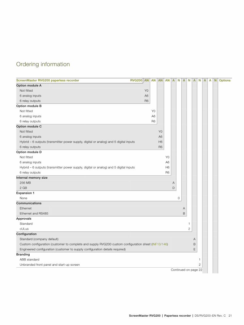
Ordering information
ScreenMaster RVG200 paperless recorder RVG200 AN AN AN AN A N A N A N A A N Options
Option module A
Not fitted
6 analog inputs
6 relay outputs
Y0
A6
R6
Option module B
Not fitted
6 analog inputs
6 relay outputs
Y0
A6
R6
Option module C
Not fitted
6 analog inputs
Hybrid – 6 outputs (transmitter power supply, digital or analog) and 5 digital inputs
6 relay outputs
Y0
A6
H6
R6
Option module D
Not fitted
6 analog inputs
Hybrid – 6 outputs (transmitter power supply, digital or analog) and 5 digital inputs
6 relay outputs
Y0
A6
H6
R6
Internal memory size
256 MB
2 GB
A
D
Expansion 1
None 0
Communications
Ethernet
Ethernet and RS485
A
B
Approvals
Standard
cULus
1
2
Configuration
Standard (company default)
Custom configuration (customer to complete and supply RVG200 custom configuration sheet (INF13/146)
Engineered configuration (customer to supply configuration details required)
A
B
E
Branding
ABB standard
Unbranded front panel and start-up screen
1
2
Continued on page 22
ScreenMaster RVG200Paperless recorder
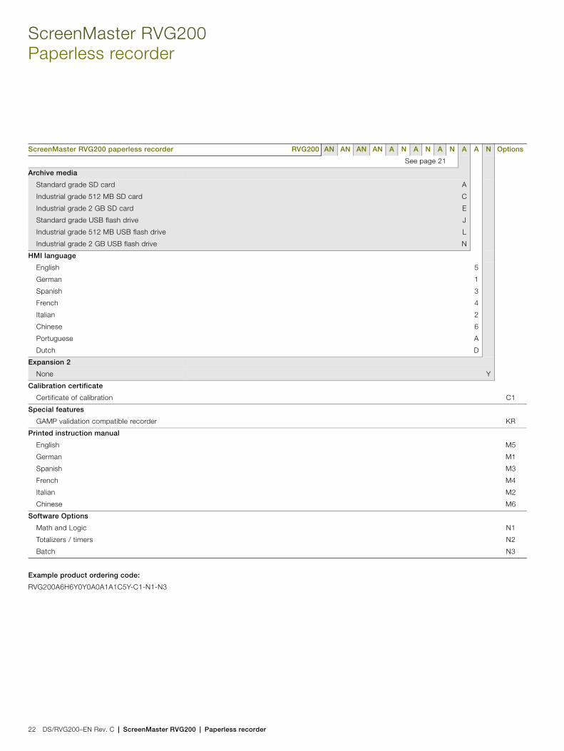
22 DS/RVG200–EN Rev. C | ScreenMaster RVG200 | Paperless recorder
See page 21
Archive media
Standard grade SD card
Industrial grade 512 MB SD card
Industrial grade 2 GB SD card
Standard grade USB flash drive
Industrial grade 512 MB USB flash drive
Industrial grade 2 GB USB flash drive
A
C
E
J
L
N
HMI language
English
German
Spanish
French
Italian
Chinese
Portuguese
Dutch
5
1
3
4
2
6
A
D
Expansion 2
None Y
Calibration certificate
Certificate of calibration C1
Special features
GAMP validation compatible recorder KR
Printed instruction manual
English
German
Spanish
French
Italian
Chinese
M5
M1
M3
M4
M2
M6
Software Options
Math and Logic
Totalizers / timers
Batch
N1
N2
N3
Example product ordering code:
RVG200A6H6Y0Y0A0A1A1C5Y-C1-N1-N3
ScreenMaster RVG200 paperless recorder RVG200 AN AN AN AN A N A N A N A A N Options
ScreenMaster RVG200 | Paperless recorder | DS/RVG200–EN Rev. C 23
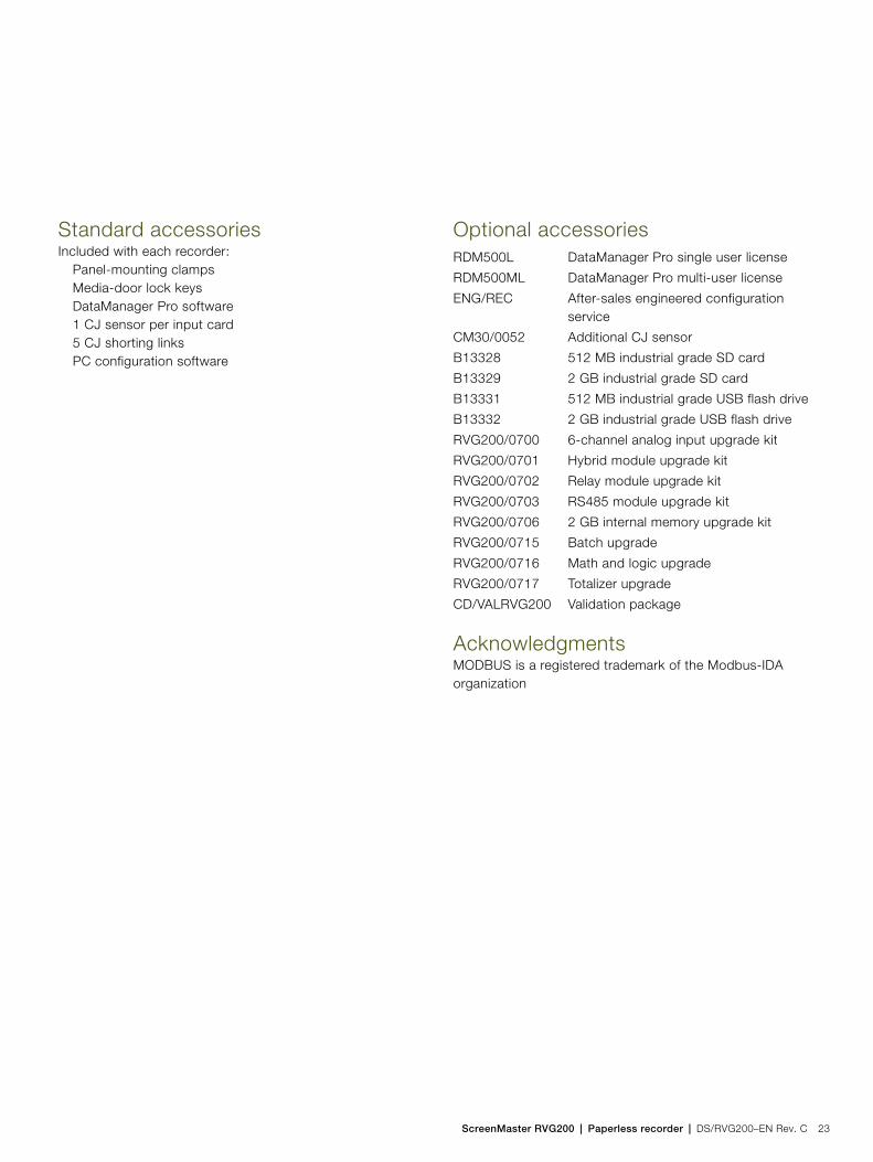
Standard accessoriesIncluded with each recorder:
Panel-mounting clampsMedia-door lock keysDataManager Pro software1 CJ sensor per input card5 CJ shorting linksPC configuration software
Optional accessories
AcknowledgmentsMODBUS is a registered trademark of the Modbus-IDA organization
RDM500L DataManager Pro single user license
RDM500ML DataManager Pro multi-user license
ENG/REC After-sales engineered configuration service
CM30/0052 Additional CJ sensor
B13328 512 MB industrial grade SD card
B13329 2 GB industrial grade SD card
B13331 512 MB industrial grade USB flash drive
B13332 2 GB industrial grade USB flash drive
RVG200/0700 6-channel analog input upgrade kit
RVG200/0701 Hybrid module upgrade kit
RVG200/0702 Relay module upgrade kit
RVG200/0703 RS485 module upgrade kit
RVG200/0706 2 GB internal memory upgrade kit
RVG200/0715 Batch upgrade
RVG200/0716 Math and logic upgrade
RVG200/0717 Totalizer upgrade
CD/VALRVG200 Validation package
Contact us
DS
/RV
G20
0–E
N R
ev. C
07.2
014ABB Limited
Process AutomationHoward RoadSt. NeotsCambridgeshire PE19 8EUUKTel: +44 (0)1480 475321Fax: +44 (0)1480 217948
ABB Inc.Process Automation125 E. County Line RoadWarminsterPA 18974USATel: +1 215 674 6000Fax: +1 215 674 7183
www.abb.com/recorders
NoteWe reserve the right to make technical changes or modify the contents of this document without prior notice. With regard to purchase orders, the agreed particulars shall prevail. ABB does not accept any responsibility whatsoever for potential errors or possible lack of information in this document.
We reserve all rights in this document and in the subject matter and illustrations contained therein. Any reproduction, disclosure to third parties or utilization of its contents in whole or in parts – is forbidden without prior written consent of ABB.
Copyright© 2014 ABBAll rights reserved
3KXR110200R1001
Sales
Service
Software

Data sheet DS/SM3000–EN Rev. AA
SM3000Multipoint videographic recorder
Raising the standards of data storage
Large clear display— 31 cm (12.1 in.) thin film transistor (TFT) color screen
Unsurpassed environmental protection— hosedown to IP66 and NEMA4X standards
Multiple point recording— up to 36 universal analog inputs
Robust and convenient archive storage— solid-state high-reliability — Compact Flash Memory Card option
Intuitive user interface— clear and simple Microsoft® Windows-style operation and
configuration menus
10BaseT Ethernet communications as standard— easy integration into PC networks— remote monitoring/access— email notification of alarms and status reports.
21 CFR Part 11 compliant data security— extensive physical and electronics security features
GAMP vailidation package— 21 CFR part 11 compliant
SM3000Multipoint videographic recorder
2 DS/SM3000–EN Rev. AA
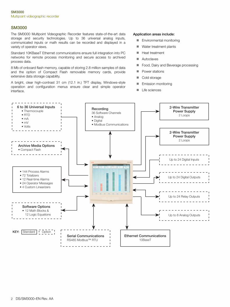
SM3000The SM3000 Multipoint Videographic Recorder features state-of-the-art datastorage and security technologies. Up to 36 universal analog inputs,communicated inputs or math results can be recorded and displayed in avariety of operator views.
Standard 10KBaseT Ethernet communications ensure full integration into PCnetworks for remote process monitoring and secure access to archivedprocess data.
8 Mb of onboard flash memory, capable of storing 2.8 million samples of dataand the option of Compact Flash removable memory cards, provideextensive data storage capability.
A bright, clear high-contrast 31 cm (12.1 in.) TFT display, Windows-styleoperation and configuration menus ensure clear and simple operatorinterface.
������������ �������� ��������� ����������������� ��
���������������� ��������� ���
������������� ������������ ������������� ������� ����������������� ����!������������"�#��������
�������������� � ��� ����$ %��&���"!��'(����#�
���� )��#*��* ����#������ �!!������� �)�+,� *-��.���/
��������� �!!������� �0$����
"������#12�)3�4�������##� ����#� !����!��� �� *-�������#����#�
$%&���'��� !����(����������)
��"��
$%&���'��� !����(����������)
��"��
/���������!��� �5#����
/���������!��� ��������
/��������� �6��������
/����+��#� !��������
Application areas include:
Environmental monitoring
Water treatment plants
Heat treatment
Autoclaves
Food, Dairy and Beverage processing
Power stations
Cold storage
Emission monitoring
Life sciences
SM3000Multipoint videographic recorder
DS/SM3000–EN Rev. AA 3
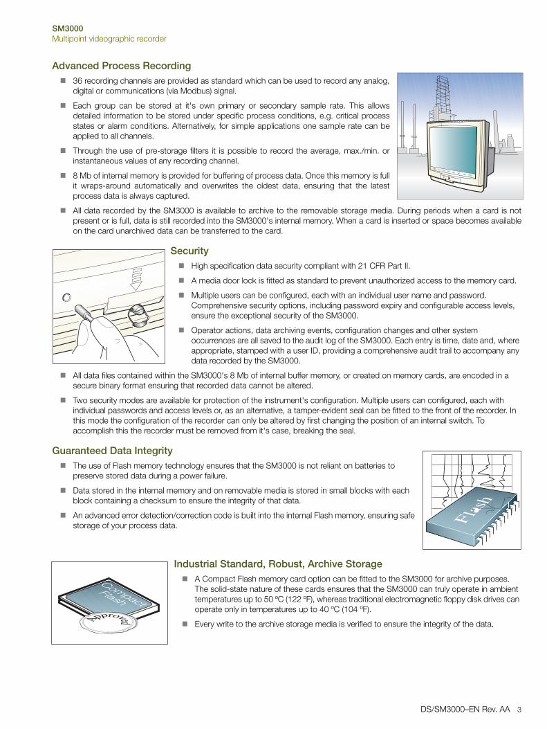
Advanced Process Recording 36 recording channels are provided as standard which can be used to record any analog,
digital or communications (via Modbus) signal.
Each group can be stored at it's own primary or secondary sample rate. This allowsdetailed information to be stored under specific process conditions, e.g. critical processstates or alarm conditions. Alternatively, for simple applications one sample rate can beapplied to all channels.
Through the use of pre-storage filters it is possible to record the average, max./min. orinstantaneous values of any recording channel.
8 Mb of internal memory is provided for buffering of process data. Once this memory is fullit wraps-around automatically and overwrites the oldest data, ensuring that the latestprocess data is always captured.
All data recorded by the SM3000 is available to archive to the removable storage media. During periods when a card is notpresent or is full, data is still recorded into the SM3000's internal memory. When a card is inserted or space becomes availableon the card unarchived data can be transferred to the card.
Security High specification data security compliant with 21 CFR Part II.
A media door lock is fitted as standard to prevent unauthorized access to the memory card.
Multiple users can be configured, each with an individual user name and password. Comprehensive security options, including password expiry and configurable access levels, ensure the exceptional security of the SM3000.
Operator actions, data archiving events, configuration changes and other system occurrences are all saved to the audit log of the SM3000. Each entry is time, date and, where appropriate, stamped with a user ID, providing a comprehensive audit trail to accompany any data recorded by the SM3000.
All data files contained within the SM3000's 8 Mb of internal buffer memory, or created on memory cards, are encoded in a secure binary format ensuring that recorded data cannot be altered.
Two security modes are available for protection of the instrument's configuration. Multiple users can configured, each with individual passwords and access levels or, as an alternative, a tamper-evident seal can be fitted to the front of the recorder. In this mode the configuration of the recorder can only be altered by first changing the position of an internal switch. To accomplish this the recorder must be removed from it's case, breaking the seal.
Guaranteed Data Integrity The use of Flash memory technology ensures that the SM3000 is not reliant on batteries to
preserve stored data during a power failure.
Data stored in the internal memory and on removable media is stored in small blocks with each block containing a checksum to ensure the integrity of that data.
An advanced error detection/correction code is built into the internal Flash memory, ensuring safe storage of your process data.
Industrial Standard, Robust, Archive Storage A Compact Flash memory card option can be fitted to the SM3000 for archive purposes.
The solid-state nature of these cards ensures that the SM3000 can truly operate in ambient temperatures up to 50 ºC (122 ºF), whereas traditional electromagnetic floppy disk drives can operate only in temperatures up to 40 ºC (104 ºF).
Every write to the archive storage media is verified to ensure the integrity of the data.
������ ���
SM3000Multipoint videographic recorder
4 DS/SM3000–EN Rev. AA
21 CFR part 11 Compliance and GAMP Validation PackageWith its comprehensive audit trail, secure archiving format and extensive physical and configuration security features, the SM3000 isideally suited to applications where compliance to 21CFR part 11 (the FDA's regulations regarding electronic record keeping) isrequired (for further information refer to INF02/70A).
In keeping with this, a template for validating the SM3000 videographic recorder is available. Following GAMP 5 (a risk-basedapproach to compliant GxP computerized systems), the template is designed to make the validation process as simple as possibleand provides an IQ and OQ that is completed at the customer site, before and after installation. Once completed, the template is thenpackaged together with other documentation relating to the system as a whole, ready to be presented to the governing regulatorybody for inspection.
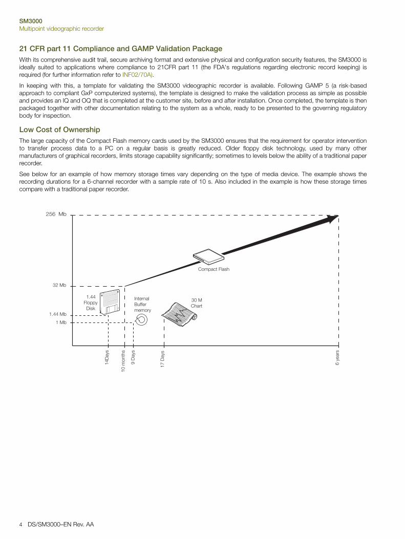
Low Cost of OwnershipThe large capacity of the Compact Flash memory cards used by the SM3000 ensures that the requirement for operator interventionto transfer process data to a PC on a regular basis is greatly reduced. Older floppy disk technology, used by many othermanufacturers of graphical recorders, limits storage capability significantly; sometimes to levels below the ability of a traditional paperrecorder.
See below for an example of how memory storage times vary depending on the type of media device. The example shows therecording durations for a 6-channel recorder with a sample rate of 10 s. Also included in the example is how these storage timescompare with a traditional paper recorder.
�7��� -
�7��� ��6���%
10� �����
5#���#� $�33������6
������� ���
����6�
�0��#���
�����6�
8���6�
2�6����
1�� -
�� -
�,2�� -

SM3000Multipoint videographic recorder
DS/SM3000–EN Rev. AA 5
&�����*����"����+�,!�-
(���������"���#
5�2,
��7,
�00
�8,
5�22 9' ���
Unsurpassed Environmental ProtectionUnique to this type of product, the SM3000 has unrivalledprotection ratings of IP66 and NEMA4X and includes afully-sealed, lockable media door. This enables the SM3000to be installed, without additional protection, in applicationsthat require frequent hosedown. With industrial standardnoise emission and immunity protection, the SM3000 alsooperates effectively in high electrical-noise environments.
Intuitive User Interface
�����/��*�3�#3����#!
��#���� ���#�
��,.���������/��*���#�:�!�����������#����#*���:��4�*�����#������� ���:��4��*�
�������)���� �6�����������#�3���������� ���#�
/�����))� ����-��4��#�#�- �*�:��4�
3������� ���*������!����; !�
0�������))� ����-��4��#������!����
�#*������� � !�
1���,"#��� �� ��/��*���#�:�!���
�#3�!�����#�&���:��4�*�����#�������� ���:��4��*�
9�4�������
� *�������
)������##� ��!
)� �$��
������<����9��� ��� ��$�� �*���)������5#�
�����#�������#*�����
)���#5#���:�
/#���
����)����
���������
�����#���� ��� ����)�����
������� ����!�
� ���':�#�
< -� �� ����5#

SM3000Multipoint videographic recorder
6 DS/SM3000–EN Rev. AA
Operator ViewsThe 36 recording channels of the SM3000 can be freely distributed between 6process groups and displayed using a number of different operator views. Inaddition to the standard strip chart views, the following views are available:
Circular Chart View
Up to six trends can be plotted on a circular chart. In addition to digitalindicators, including alarm status and totalizer values, a log is constantlyin view showing a list of recent alarm activity.
Digital Indicator View
Process value, engineering units, channel tag, totalizers and alarm statusare all displayed clearly. An overview screen provides an at-a-glance viewof all 36 recording channels.
Process View
Provides an at-a-glance summary of each channel, including detailedalarm, totalizer and statistical (min., max. & average) information.
Bargraph View
Horizontal or vertical formats, including min./max. and alarm trip pointmarkers.
Historical LogsProviding functions unavailable in paper-based recorders, three full-time anddate-stamped historical logs ensure complete validity of the recorder and it'sdata. Any or all of these logs can be archived to the removable memory card.
Totalizer Log
All totalizer activity, e.g. starts, stops and resets, are recorded by thetotalizer log. In addition individual log intervals can be configured for eachtotalizer, allowing total values to be logged regularly.
Alarm Event Log
A detailed history of all alarm occurrences, including active and inactivetransitions plus acknowledgement details.
Audit Log
The highly-detailed secure log of all system events gathered by the AuditLog provides comprehensive evidence of the integrity, validity andtraceability of data recorded by the SM3000. Included in the log areconfiguration changes, data archiving events, calibration adjustments,details of remote accesses and many more key events, all marked withoperator IDs where applicable.
ConfigurationA simple Windows-style structure provides an exceptionally easy approach tothe setup of the SM3000. Text and numerical information is entered veryquickly via an on-screen keyboard. Navigation of configuration menus isperformed via the cursor keys and the pop-up menu.
It is also possible to configure the SM3000 via a Windows-based PCconfiguration package.

SM3000Multipoint videographic recorder
DS/SM3000–EN Rev. AA 7
On-line Data ReviewThe SM3000 provides a number of unique features to provide a clear view of yourprocess
The screen interval can be altered to display between 48 s and 14 days of information, without it affecting the sample rate. This gives you the ability to 'zoom in' to a close-up view of the most current data or 'zoom out' to get the big picture.
Individual traces can be temporarily removed from the screen to enable clear comparison of two or more trends.
The SM3000 can easily review all historical data in the 8 Mb internal buffer memory at the touch of a button. During this time, recording of the process data to the internal memory remains unaffected.
Off-Line Review and AnalysisUsing ABB's DataManager Pro software, archived process data and historical logsrecorded to a removable media card can be reviewed easily.
Database management of data files provided by DataManager Pro ensures simple, secure long-term storage and retrieval of historical data.
The graphing capabilities provided by DataManager Pro ensure easy interrogation of process data.
The validity of all data files is always checked by DataManager Pro during the storage and retrieval process, ensuring maximum data integrity.
For further information on the capabilities of DataManager, Pro refer to data sheetDS/RDM500–EN.

SM3000Multipoint videographic recorder
8 DS/SM3000–EN Rev. AA
Math and LogicAvailable as an option are advanced math and logic capabilities. 12multi-element math and 12 multi-element logic equations can beconfigured. Equations can be nested into each other to provideextensive capabilities.
Mean, standard deviation and rolling averaging functions areprovided.
Standard addition, subtraction, multiplication and division arecomplemented with Log, Ln, Square root, power, Sin, Cos, Tanand absolute functions.
Switching of process signals can be achieved via thehigh/low/mid signal selection and multiplexing functions.
Predefined equations are provided for relative humidity and F0
measurements.
AND, NAND, OR, NOR, XOR and NOT operators are availablewithin the logic equations.
All math and logic equation results can be recorded on the display ofthe SM3000 and archived to the removable media. Detailed diagnosticfunctions are provided for both the math and logic equations.
Batch RecordingA batch recording option enables simple recording and reviewing ofbatch processes. When a batch is started it is tagged with a uniquebatch number, operator identification and three user-definabledescription fields. All information is entered on-screen with a historyfunction allowing quick entry of commonly repeated descriptions.
Using DataManager Pro software batches can be simply and quicklytraced for review using the unique batch number and descriptioninformation entered at the time of recording. Additional functionalityprovides the ability to search and sort batch records for an entireproduction facility in many ways, including by product type, operatorand time and date of processing.

SM3000Multipoint videographic recorder
DS/SM3000–EN Rev. AA 9
Ethernet CommunicationsThe SM3000 provides 10BaseT Ethernet communications as standard via a standard RJ45 connector. The SM3000 usesindustry-standard protocols TCP/IP, FTP and HTTP enabling easy integration into existing PC networks.
Data File Access via FTP (File Transfer Protocol)The SM3000 features FTP server functionality that provides high-speed access viaEthernet to data archived by the recorder.
Using a standard web-browser or other similar FTP client, data files contained within the recorder's internal memory and removable memory card can be accessed remotely and transferred to a PC or network drive.
8 individual FTP users can be programmed into the SM3000. Access rights can be configured for each user specifying their access level.
All FTP log-on activity is recorded in the audit log of the SM3000.
Using the SM series complementary FTS (File Transfer Scheduler) software, data files from multiple recorders can be backed-up automatically to a PC or network drive for long term storage, ensuring the security of valuable process data and minimizing operator intervention.
Embedded Web ServerContained within the SM3000 is an embedded web-server, enablingaccess to web pages created within the recorder. The use of HTTP(Hyper Text Transfer Protocol) enables standard web browsers to viewthese pages.
The web pages show the current display of the recorder, detailed information on process signals, alarm conditions, totalizer values, an overview screen showing the status of all 36 recording channels and other key process information.
The historical logs stored in the SM3000's internal buffer memory can be displayed in full from within the web pages.
Operator messages can be entered via the web server enabling comments to be logged to the recorder.
All of the information displayed on the web pages is regularly refreshed enabling them to be used as a process supervision tool.
On-line DemonstrationA demonstration of these features is available from an on-line recorderaccessible via the internet. In the address bar of your web browser enter'http://217.46.239.73'.
Remote Access/MonitoringEthernet communications can provide a link to recorders installed in remotelocations. By using a dial-up router, multiple SM3000 recorders can beinstalled in remote locations and accessed via a public telephone networkwhen required.
Email NotificationUsing its inbuilt SMTP client the SM3000 is able to email notification ofimportant events. Emails triggered from process alarms or other criticalprocess events can be sent to multiple recipients. The recorder can also beprogrammed to email reports of the current status at specific times during theday. Status report content can be tailored to suit your specific process needs.
����� ��#�
����)��:�� ����)��:��
'����#��
������� ����#*=������ �"!�
*��
'����#��
��- ���� ���#�9��4�%
��� ���������

SM3000Multipoint videographic recorder
10 DS/SM3000–EN Rev. AA
Specification
Operation and ConfigurationConfiguration
Via tactile membrane keys on front panel or PC Configuration using removable media card
Multiple configuration files can be stored in internal (up to 5 files) orexternal memory (with removable media option fitted)
DisplayThin film transistor (TFT), active-matrix, color, liquid crystal display(LCD) with built-in backlight
Low-reflective, 31 cm (12.1 in.) diagonal display area, 480,000 pixel display*
*Note. A small percentage of the display pixels may be eitherconstantly active or inactive. Max. percentage of inoperative pixels <0.01 %.
ScreensaverCan be programmed to dim the backlight if operator keys are notpressed for a selected period of time
Languages English, German, French, Italian and Spanish
Dedicated operator keys Group select
View select
Menu key
Left cursor
Right cursor
Up/Increment key
Down/Decrement key
Enter key
Vertical chart screen intervalsSelectable from 48 s to 14 days
Horizontal chart screen intervalsSelectable from 70 s to 20 days
Circular chart durationSelectable from 9 minutes to 32 days
Chart scalesIndependent primary and secondary ranges for each channel
Vertical/horizontal chart divisionsProgrammable for up to 10 major and 10 minor divisions
Circular chart divisionsProgrammable up to 10 divisions
Chart annotationAlarm and operator messages may be annotated on the chart
Icons to identify the type of event, time of occurrence and tag aredisplayed
Operator Views
Viewing angle — Horizontal 55 º typ. (left side, right side)
Vertical 50 º from below, 40 º from above
Views Available
Contents Chart Bargraph Digital Indicator Process
Instantaneous values/states
Units of measure
Short tags
Long tags — — —
Alarm status
Alarm trip markers — — —
Alarm trip values — — —
Max./Min. markers — — —
Analog bargraphs — — —
Totalizer values & units of measure — —
Totalizer tags — — —
Max., min. and average batch values — — —
Graphical view of historical data — — —

SM3000Multipoint videographic recorder
DS/SM3000–EN Rev. AA 11
SecurityConfiguration security
Setup security
Users
Electronic signature
Standard FunctionalityOperator MessagesNumber
24 configurable messages of up to 20 characters each
1 operator defined message of up to 20 characters
TriggerVia front panel or digital signals
Recording in alarm/event logCan be enabled or disabled on configuration
Process AlarmsNumber
144 (4 per recording channel)
Update rateUp to 12 alarms processed every 100 ms, e.g. with 36 alarmsenabled each alarm is updated once every 300 ms.
TypesHigh/low: process, latch & annunciator, delayed process
Rate: fast/slow
Tag20-characters tag for each alarm
HysteresisProgrammable value and time hysteresis 1 to 9999 s
Alarm enableAllows alarm to be enabled/disabled via a digital input
Alarm log enableRecording of alarm state changes in the alarm/event log can beenabled/disabled for each alarm
AcknowledgementVia front panel or digital signals
Real-time AlarmsNumber
12
ProgrammableDay of the week, 1st of month, start and duration times
Password protection Access to configuration is allowed only after the user has entered a password
Internal switch protection Access to configuration is allowed only after a hardware switch has been set. This switch is situated behind a tamper evident seal
Configuration Can be configured for password protection or free access to setup levels
Number of users Up to 15
Usernames Up to 20 characters, Usernames are unique, i.e. names cannot be repeated
Access privileges Setup access — Yes/No
Electronic signature access — Yes/No
Configuration access — None/load file only/limited/full
Passwords Up to 20 characters
A minimum required password length of 4 to 20 characters can be configured and a password expiry time can be applied to eliminate password ageing
Password failure limit Configurable for 1 to 10 consecutive occasions or 'infinite'
A user is deactivated if a wrong password is entered repeatedly
Deactivation of inactive users Can be disabled or configured for 7, 14, 30, 60, 90, 180 or 360 days of inactivity
Users are deactivated (by removal of access privileges) after a period of inactivity
Protection Only accessible to users with electronic signature access privileges
Access requires a valid username and password
Function Provides an electronic equivalent to the signing of a conventional paper chart
Enables operator to securely approve recorded data
Content Date/Time, operator ID and operator defined 20-character message are stored in the alarm/event log and can be displayed on the chart

SM3000Multipoint videographic recorder
12 DS/SM3000–EN Rev. AA
TotalizerNumber
72 (2 per recording channel) 10-digit totals
TypeAnalog or digital, batch and secure totals
Statistical calculationsAverage, maximum, minimum (for analog signals)
Date and time of max. and min, values
Update rateUp to 4 totalizers processed every 100 ms, e.g. with 12 totalizersenabled each total is updated once every 300 ms.
Custom LinearizationNumber
4
Number of breakpoints20 per linearizer
Number of Channels v. Number of Groups
Recording — to Internal MemoryData Channels
Internal buffer memory8 Mb Flash memory provides storage for 2.9 million samples
Oldest data is automatically overwritten by new data when memoryis full
Data integrity checksChecksum for each block of data samples
48-bit code for error detection/correction built-in
Independent process groups6
No. of recording channels36
SourcesAnalog inputs, Modbus input, any digital signal
FiltersProgrammable for each channel to allow recording ofinstantaneous values, average, max., min. and max. & min. valueover sample time
Primary/secondary sample ratesProgrammable from 0.1 s to 12 hours for each process group
Primary/secondary sample rate selectionVia any digital signal or from password protected menu
Recording start/stop controlVia any digital signal or from password protected menu
Recording DurationApproximate duration calculated for continuous recording of 12 channels of analog data (for 24 channels divide by 2, for 6 channels multiply by 2 etc.)
Groups Channels per Group
1, 2, 3 Up to 12
4 Up to 9
5 Up to 7
6 Up to 6
Sample Rate 1 s 10 s 40 s 60 s 120 s 480 s
Internal Flash buffer memory 11/2 days 271/2 days 31/2 months 51/2 months 11 months 31/2 years
Sample Rate 1 s 10 s 40 s 60 s 120 s 480 s
512 Mb Compact Flash 8 months 6 years 26 years 40 years 79 years 319 years
1 Gb Compact Flash 1 year 13 years 52 years 77 years 155 years 623 years

SM3000Multipoint videographic recorder
DS/SM3000–EN Rev. AA 13
Historical LogsTypes
Alarm/Event, Totalizer and Audit logs
No. of records in each historical logUp to 200 in internal memory
Oldest data is automatically overwritten by new data when log is full
Historical Logs
Archiving — To Memory CardFile types that can be saved to removable media
Recorded data for each channel
Alarm event log for each group
Totalizer log for each group
Audit log
Configuration
File StructureBinary encoded with built-in data integrity checks
Automatic updating of archive filesAt regular time intervals according to the sample rate
When a media card is inserted
Data verificationCarried out automatically on all writes to removable-media files
Card compatibilityABB recorders comply with approved industry standards for memorycards and ABB has fully tested and recommend the use of SanDiskStandard Grade or Ultra II memory cards. Other brands may not befully compatible with this device and therefore may not functioncorrectly
Card sizeCards up to 4 Gb capacity may be used
Log Type Alarm/Event Log Totalizer Log Audit Log
Log Entry Events
InformationRecorded in Logs
• Alarm state changes
• Operator messages
• Electronic signatures
• User defined logging intervals
• Totalizer stop/start, reset, wrap
• Power up/down
• Configuration/calibration changes
• System events
• Errors, operator actions
In Log On Screen In Log On Screen In Log On Screen
Date & time of event
Type of event
Tag — —
Source tag — — — —
Alarm trip value & units of measure — — — — —
Alarm trip — — — —
Alarm acknowledgement state — — — —
Operator ID — — —
Description — — — —
Batch total and units of measurement — — — —
Max., Min. and average values plus units — — — —
Secure total — — — — —
Time & date of min./max. values — — — —
SM3000Multipoint videographic recorder
14 DS/SM3000–EN Rev. AA
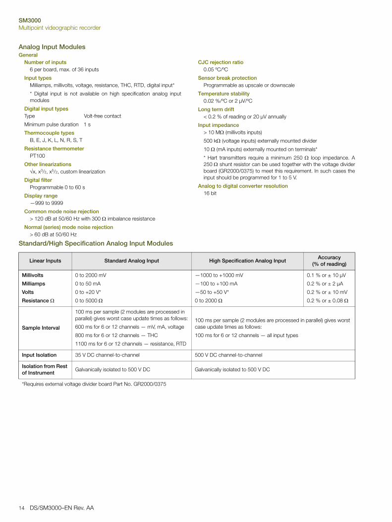
Analog Input ModulesGeneral
Number of inputs6 per board, max. of 36 inputs
Input typesMilliamps, millivolts, voltage, resistance, THC, RTD, digital input*
* Digital input is not available on high specification analog inputmodules
Digital input typesType Volt-free contact
Minimum pulse duration 1 s
Thermocouple typesB, E, J, K, L, N, R, S, T
Resistance thermometerPT100
Other linearizationsx, x3/2, x5/2, custom linearization
Digital filterProgrammable 0 to 60 s
Display range—999 to 9999
Common mode noise rejection> 120 dB at 50/60 Hz with 300 imbalance resistance
Normal (series) mode noise rejection> 60 dB at 50/60 Hz
CJC rejection ratio0.05 ºC/ºC
Sensor break protectionProgrammable as upscale or downscale
Temperature stability0.02 %/ºC or 2 µV/ºC
Long term drift< 0.2 % of reading or 20 µV annually
Input impedance> 10 M (millivolts inputs)
500 k (voltage inputs) externally mounted divider
10 (mA inputs) externally mounted on terminals*
* Hart transmitters require a minimum 250 loop impedance. A250 shunt resistor can be used together with the voltage dividerboard (GR2000/0375) to meet this requirement. In such cases theinput should be programmed for 1 to 5 V.
Analog to digital converter resolution16 bit
Standard/High Specification Analog Input Modules
Linear Inputs Standard Analog Input High Specification Analog InputAccuracy
(% of reading)
Millivolts
Milliamps
Volts
Resistance
0 to 2000 mV
0 to 50 mA
0 to +20 V*
0 to 5000
—1000 to +1000 mV
—100 to +100 mA
—50 to +50 V*
0 to 2000
0.1 % or ± 10 µV
0.2 % or ± 2 µA
0.2 % or ± 10 mV
0.2 % or ± 0.08
Sample Interval
100 ms per sample (2 modules are processed in parallel) gives worst case update times as follows:
600 ms for 6 or 12 channels — mV, mA, voltage
800 ms for 6 or 12 channels — THC
1100 ms for 6 or 12 channels — resistance, RTD
100 ms per sample (2 modules are processed in parallel) gives worst case update times as follows:
100 ms for 6 or 12 channels — all input types
Input Isolation 35 V DC channel-to-channel 500 V DC channel-to-channel
Isolation from Rest of Instrument
Galvanically isolated to 500 V DC Galvanically isolated to 500 V DC
*Requires external voltage divider board Part No. GR2000/0375
SM3000Multipoint videographic recorder
DS/SM3000–EN Rev. AA 15
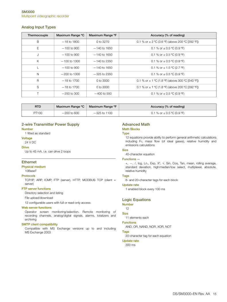
Analog Input Types
2-wire Transmitter Power SupplyNumber
1 fitted as standard
Voltage24 V DC
DriveUp to 45 mA, i.e. can drive 2 loops
EthernetPhysical medium
10BaseT
ProtocolsTCP/IP, ARP, ICMP, FTP (server), HTTP, MODBUS TCP (client +server)
FTP server functionsDirectory selection and listing
File upload/download
12 configurable users with full or read-only access
Web server functionsOperator screen monitoring/selection. Remote monitoring ofrecording channels, analog/digital signals, alarms, totalizers andarchiving
SMTP client compatibilityCompatible with MS Exchange versions up to and includingMS Exchange 2003
Advanced MathMath BlocksType
12 equations provide ability to perform general arithmetic calculationsincluding F0, mass flow (of ideal gases), relative humidity andemissions calculations
Size40-character equation
Functions —+, —, /, log, Ln., Exp, Xn, , Sin, Cos, Tan, mean, rolling average,standard deviation, high/median/low select, multiplexer, absolute,relative humidity
Tags8- and 20-character tags for each block
Update rate1 enabled block every 100 ms
Logic EquationsNumber
12
Size11 elements each
FunctionsAND, OR, NAND, NOR, XOR, NOT
Tags20-character tag for each equation
Update rate300 ms
Thermocouple Maximum Range ºC Maximum Range ºF Accuracy (% of reading)
B —18 to 1800 0 to 3270 0.1 % or ± 2 ºC (3.6 ºF) (above 200 ºC [392 ºF])
E —100 to 900 —140 to 1650 0.1 % or ± 0.5 ºC (0.9 ºF)
J —100 to 900 —140 to 1650 0.1 % or ± 0.5 ºC (0.9 ºF)
K —100 to 1300 —140 to 2350 0.1 % or ± 0.5 ºC (0.9 ºF)
L —100 to 900 —140 to 1650 0.1 % or ± 1.5 ºC (2.7 ºF)
N —200 to 1300 —325 to 2350 0.1 % or ± 0.5 ºC (0.9 ºF)
R —18 to 1700 0 to 3000 0.1 % or ± 1 ºC (1.8 ºF) (above 300 ºC [540 ºF])
S —18 to 1700 0 to 3000 0.1 % or ± 1 ºC (1.8 ºF) (above 200 ºC [392 ºF])
T —250 to 300 —400 to 550 0.1 % or ± 0.5 ºC (0.9 ºF)
RTD Maximum Range ºC Maximum Range ºF Accuracy (% of reading)
PT100 —200 to 600 —325 to 1100 0.1 % or ± 0.5 ºC (0.9 ºF)
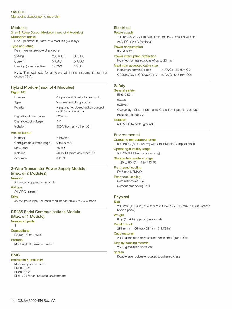
SM3000Multipoint videographic recorder
16 DS/SM3000–EN Rev. AA
Modules3- or 6-Relay Output Modules (max. of 4 Modules)Number of relays
3 or 6 per module, max. of 4 modules (24 relays)
Type and ratingRelay type single-pole changeover
Note. The total load for all relays within the instrument must notexceed 36 A.
Hybrid Module (max. of 4 Modules)Digital I/O
Analog output
2-Wire Transmitter Power Supply Module(max. of 2 Modules)Number
2 isolated supplies per module
Voltage24 V DC nominal
Drive45 mA per supply, i.e. each module can drive 2 x 2 = 4 loops
RS485 Serial Communications Module(Max. of 1 Module)Number of ports
1
ConnectionsRS485, 2- or 4-wire
ProtocolModbus RTU slave + master
EMCEmissions & Immunity
Meets requirements of:EN50081-2EN50082-2EN61326 for an industrial environment
ElectricalPower supply
100 to 240 V AC ±10 % (90 min. to 264 V max.) 50/60 Hz
24 V DC ± 2.4 V (optional)
Power consumption35 VA max.
Power interruption protectionNo effect for interruptions of up to 20 ms
Maximum accepted cable sizeInstrument terminal block 14 AWG (1.63 mm OD)
GR2000/0375, GR2000/0377 15 AWG (1.45 mm OD)
SafetyGeneral safety
EN61010-1
cULus
cCSAus
Overvoltage Class III on mains, Class II on inputs and outputs
Pollution category 2
Isolation500 V DC to earth (ground)
EnvironmentalOperating temperature range
0 to 50 ºC (32 to 122 ºF) with SmartMedia/Compact Flash
Operating humidity range5 to 95 % RH (non-condensing)
Storage temperature range—20 to 60 ºC (—4 to 140 ºF)
Front panel sealingIP66 and NEMA4X
Rear panel sealing(with rear cover) IP40
(without rear cover) IP20
PhysicalSize
288 mm (11.34 in.) x 288 mm (11.34 in.) x 195 mm (7.68 in.) (depthbehind panel)
Weight8 kg (17.4 lb) approx. (unpacked)
Panel cutout281 mm (11.06 in.) x 281 mm (11.06 in.)
Case material20 % glass-filled polyester/stainless steel (grade 304)
Display housing material25 % glass-filled polyester
ScreenDouble layer polyester coated toughened glass
Voltage 250 V AC 30V DC
Current 5 A AC 5 A DC
Loading (non-inductive) 1250VA 150
Number 6 inputs and 6 outputs per card
Type Volt-free switching inputs
Polarity Negative, i.e. closed switch contact or 0 V = active signal
Digital input min. pulse 125 ms
Digital output voltage 5 V
Isolation 500 V from any other I/O
Number 2 isolated
Configurable current range 0 to 20 mA
Max. load 750
Isolation 500 V DC from any other I/O
Accuracy 0.25 %

SM3000Multipoint videographic recorder
DS/SM3000–EN Rev. AA 17
Electrical Connections
*Note. 24 V DC instrument power supply must be specified when ordering.
�������(� ���
��1�,2�+8�0�����1���,�2���+�8�0
*��
*��
*�1
*��
*�,
*�2
*�
*�
*1
*�
*,
*2
��
��
��
��
>
?�0�
>
?�0�
�2�32� 2�.2��2�*
4���5��#��@���#� �*�:�*���A�����#7�<��000;01�,B������(����*3��������##� �3��: ��!���#������#!����-:����
'����#����##���#A�C�,��##���B
��1�,2�+8�0�����1���,�2���+�8�0
9�
9�
�
9�
9�
�
9�
9�
�
9�
9�
�
9�
9�
�
9�
9�
�
6
��1�,2�+8�0�����1���,�2���+�8�0
>
?
����@��)/�,���
����@��)/�,���
>
?
>�)�+,
?>?��
�@;�@
�@
��1�,2�+
"
9
>?
����@��)/�,��
>�=��DE���
��
���
>�=� ��
���
>�=� ��
���
>�=� ��
���
>�=� ��
���
?
>�=��DE ��
��
���
?
?
?
?
?
��1�,2�+8�0�����1���,�2���+�8�0
�DE���
�DE���
�DE���
�DE���
78
<��000;01�,
6
� 3 .
�����#������ "���) '9�( �
0
��1�,2�+8�0�����1���,�2���+�8�0
"�:;<������=)>�� (����������)
>������D
?
�����5��������4������� 6�!��#*��- ������-��##���*�������!��#*����*
� * 0 =
�#��#���6;����:��"'�
���#�����"'�
�2�*2�02�= 02�=

SM3000Multipoint videographic recorder
18 DS/SM3000–EN Rev. AA
Overall Dimensions
Standard AccessoriesIncluded with each recorder:
Panel-mounting ClampsMedia-door Lock keysShunt Resistors (1 per analog input)Compact Flash Card (only with Compact Flash Memory Cardoption)
Optional Accessories
Compact Flash Cards
Card Reader
Other
Acknowledgements and TrademarksMicrosoft is a registered trademark of Microsoft Corporation inthe United States and/or other countries
Modbus is a registered trademark of the Modbus-IDAorganization
<��%��
<��%��
��A07�2B
1+�A�7,B
���A07,,B
�2�A�70�B
�2+�A272B�++�A��71�B �+�
��#� �������
>��?�0
�+�>��?�0�++
A��71�B
8�A071,B
A��702 B>�070�?�0
A��702 B>�070�?�0
10�A�7�B
����#��#���#����A�#7B
B12568 Compact Flash Card (2 GB)
B12028 Compact Flash Reader (USB Interface)
GR2000/0375 Voltage divider board (2 to 20 V) – per voltage input channel
GR2000/0375 Voltage divider board fitted with a 250 shunt resistor
RDM500–CD DataManager Pro software
RDM500L DataManager Pro single user license
RDM500ML DataManager Pro multi-user license
CD/VALSM3000 SM3000 validation package template
ENG/REC After-sales engineered configuration servcice
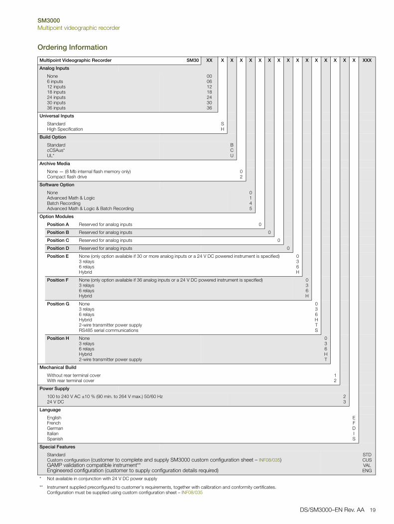
SM3000Multipoint videographic recorder
DS/SM3000–EN Rev. AA 19
Ordering Information
Multipoint Videographic Recorder SM30 XX X X X X X X X X X X X X X X X XXX
Analog Inputs
None6 inputs12 inputs18 inputs24 inputs30 inputs36 inputs
00061218243036
Universal Inputs
StandardHigh Specification
SH
Build Option
StandardcCSAus*UL*
BCU
Archive Media
None — (8 Mb internal flash memory only)Compact flash drive
02
Software Option
NoneAdvanced Math & LogicBatch RecordingAdvanced Math & Logic & Batch Recording
0145
Option Modules
Position A Reserved for analog inputs 0
Position B Reserved for analog inputs 0
Position C Reserved for analog inputs 0
Position D Reserved for analog inputs 0
Position E None (only option available if 30 or more analog inputs or a 24 V DC powered instrument is specified)3 relays6 relaysHybrid
036H
Position F None (only option available if 36 analog inputs or a 24 V DC powered instrument is specified)3 relays6 relaysHybrid
036H
Position G None3 relays6 relaysHybrid2-wire transmitter power supplyRS485 serial communications
036HTS
Position H None3 relays6 relaysHybrid2-wire transmitter power supply
036HT
Mechanical Build
Without rear terminal coverWith rear terminal cover
12
Power Supply
100 to 240 V AC ±10 % (90 min. to 264 V max.) 50/60 Hz24 V DC
23
Language
EnglishFrenchGermanItalianSpanish
EFDIS
Special Features
StandardCustom configuration (customer to complete and supply SM3000 custom configuration sheet – INF08/035)GAMP validation compatible instrument**Engineered configuration (customer to supply configuration details required)
STDCUSVALENG
*
**
Not available in conjunction with 24 V DC power supply
Instrument supplied preconfigured to customer's requirements, together with calibration and conformity certificates.Configuration must be supplied using custom configuration sheet – INF08/035

Contact us
DS
/SM
3000
–EN
Rev
. AA
10.2
014ABB Limited
Process AutomationHoward RoadSt. NeotsCambridgeshire PE19 8EUUKTel: +44 (0)1480 475321Fax: +44 (0)1480 217948
ABB Inc.Process Automation125 E. County Line RoadWarminsterPA 18974USATel: +1 215 674 6000Fax: +1 215 674 7183
www.abb.com/recorders
NoteWe reserve the right to make technical changes or modify the contents of this document without prior notice. With regard to purchase orders, the agreed particulars shall prevail. ABB does not accept any responsibility whatsoever for potential errors or possible lack of information in this document.
We reserve all rights in this document and in the subject matter and illustrations contained therein. Any reproduction, disclosure to third parties or utilization of its contents in whole or in parts – is forbidden without prior written consent of ABB.
Copyright© 2014 ABBAll rights reserved
3KXR103001R1001
Sales
Service
Software

Data sheet DS/RDM500–EN Rev. F
DataManager Pro RDM500Advanced data review software
Complete management of ScreenMaster data archives
Measurement made easy
Guaranteed data security— Automatic validation of data files
Long term data management— Database storage and management of process data
Information at your fingertips— Automatic data collection direct from multiple recorders via
Ethernet
Secure data distribution— Create packages of specific process data
DataManager Pro
DataManager Pro is an advanced process data management and analysis application used to store and review data archived by ScreenMaster videographic recorders. Stored data can be displayed in both tabular and graphical format and analyzed using the extensive array of tools provided. A ScreenMaster's archived data can be transferred to DataManager Pro either manually, via the ScreenMaster's memory card, or automatically, via Ethernet communications. DataManager Pro provides automatic, secure, long-term process data storage and enables data to be retrieved quickly when required.
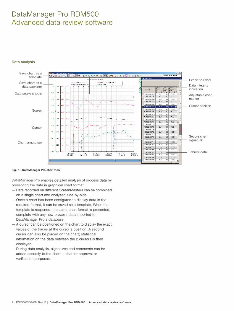
DataManager Pro RDM500Advanced data review software
2 DS/RDM500–EN Rev. F | DataManager Pro RDM500 | Advanced data review software
Data analysis
DataManager Pro enables detailed analysis of process data by presenting the data in graphical chart format.— Data recorded on different ScreenMasters can be combined
on a single chart and analyzed side-by-side.— Once a chart has been configured to display data in the
required format, it can be saved as a template. When the template is reopened, the same chart format is presented, complete with any new process data imported to DataManager Pro's database.
— A cursor can be positioned on the chart to display the exact values of the traces at the cursor's position. A second cursor can also be placed on the chart; statistical information on the data between the 2 cursors is then displayed.
— During data analysis, signatures and comments can be added securely to the chart – ideal for approval or verification purposes.
Fig. 1: DataManager Pro chart view
Save chart as atemplate
Save chart as adata package
Data analysis tools
Scales
Cursor
Chart annotation
Export to Excel
Data integrity indication
Adjustable chart marker
Cursor position
Secure chart signature
Tabular data

DataManager Pro RDM500 | Advanced data review software | DS/RDM500–EN Rev. F 3
Data managementAt the heart of DataManager Pro is a secure database.— Data from any number of ScreenMaster recorders can be
imported manually, via a recorder's memory card, or automatically, via Ethernet communications.
— Once imported into the database, data is conveniently and securely held for long-term storage.
— When required, data can be displayed quickly and easily by either opening a predefined chart template or selecting the channels and time period required.
Batch dataA batch record recorded by a ScreenMaster can be instantly analyzed using DataManager Pro.— Powerful search functionality enables batch records to be
located easily and displayed regardless of when, or on which instrument, it was recorded.
— Batches with common attributes (for example, date of manufacture, product type or product line) can be identified easily and charts drawn for side-by-side comparison.
— Batch information entered by the operator at the time the batch was recorded is presented clearly at the base of the chart.
Data distributionData from DataManager Pro's database can be exported for use and analysis elsewhere.— Secure data packages (that maintain the original data file
integrity) can be created and passed to another DataManager Pro user for analysis. This feature is ideal for ScreenMaster users who process third-party products as it enables the product owner to be given a package of data relating to the processing of their product and analyze it using their own copy of DataManager Pro. A free-of-charge (unlicensed) version of DataManager Pro is all that is required for such analysis.
— Data can also be exported in Excel spreadsheet format.
Recorder networking
When connected to ScreenMaster recorders via an Ethernet network, DataManager Pro provides excellent security for, and ease of access to, process data.— DataManager Pro's database can be located on a secure,
backed-up network drive:—enhances data security
— DataManager Pro can import new data automatically from any number of ScreenMaster recorders on a scheduled basis:—ensures the latest process data is always available for
review— When located on a shared network drive, data from
DataManager Pro's database is accessible to multiple users:—company-wide accessibility to process data speeds up
the review and approval process and increases productivity
— DataManager Pro can synchronize the clocks of multiple ScreenMaster recorders using Ethernet communications:—enhances the accuracy of side-by-side comparison of
process data
Fig. 2: Network diagram
Datamanager Pro database on secure server
Production office
Quality control
General office
Production facility
Ethernet

Contact us
DS
/RD
M50
0–E
N R
ev. F
08.2
014
Functionality
DataManager Pro can be used either licensed or unlicensed; when used unlicensed, it offers basic functionality only. To enable full functionality, the software must be licensed. Table 1 details the features available in each version.After the first installation DataManager Pro will work in licensed (full functionality) mode for a 30 day evaluation period.
Minimum system requirements— 2 GHz Intel™ Pentium™ Dual Core processor or equivalent
with 1 GB of RAM— Windows 7™ SP2 (32 or 64 bit)
or Windows 8.1™ Pro (32 or 64 bit) operating systems— 50 MB of free hard disk space— 1024 x 768 minimum screen resolution
Compatible productsDatamanager Pro can be used to analyze data from the following products:— SM series videographic recorders *— C1300 circular chart recorder— Aztec series analyzers— Navigator series analyzers* Recorders manufactured from 2003 onwards
Ordering informationDataManager Pro is available for download fromABB.com/recorders— Single user license – part number RDM500L**— Multi-user site licence – part number RDM500ML***— Software CD – part number RDM500CD**The purchase of a single-user license authorizes the installation and use of DataManager Pro on a single PC.***The purchase of a multi-user site license authorizes the installation and use of DataManager Pro on multiple PCs at a single (geographic) site.A geographic site is defined as a site covered by a single postal address.
Feature
Unlicensed
(Basic functionality)
Licensed
(Full functionality)
Manual data import X X
Scheduled automatic data
import via ethernet (FTS)
X
Database data management X X
Data quick view X X
Chart display X X
Tabular display X X
Log files display X X
Chart printing X X
Predefined chart templates X
Chart signature X
Create chart package X
Display chart package X X
Export to Excel X
Batch data search and access X X
Table 1: Licensed / unlicensed features
AcknowledgementsWindows 7, Windows 8 and Access are registered trademarks of Microsoft Corporation in the United States and/or other countries.Intel and Pentium are registered trademarks of Intel Corporation in the United States and/or other countries.
NoteWe reserve the right to make technical changes or modify the contents of this document without prior notice. With regard to purchase orders, the agreed particulars shall prevail. ABB does not accept any responsibility whatsoever for potential errors or possible lack of information in this document.
We reserve all rights in this document and in the subject matter and illustrations contained therein. Any reproduction, disclosure to third parties or utilization of its contents in whole or in parts – is forbidden without prior written consent of ABB.
Copyright© 2014 ABBAll rights reserved
3KXR071301R1001
ABB LimitedProcess AutomationHoward RoadSt. NeotsCambridgeshire PE19 8EUUKTel: +44 (0)1480 475321Fax: +44 (0)1480 217948
www.abb.com
Sales Software
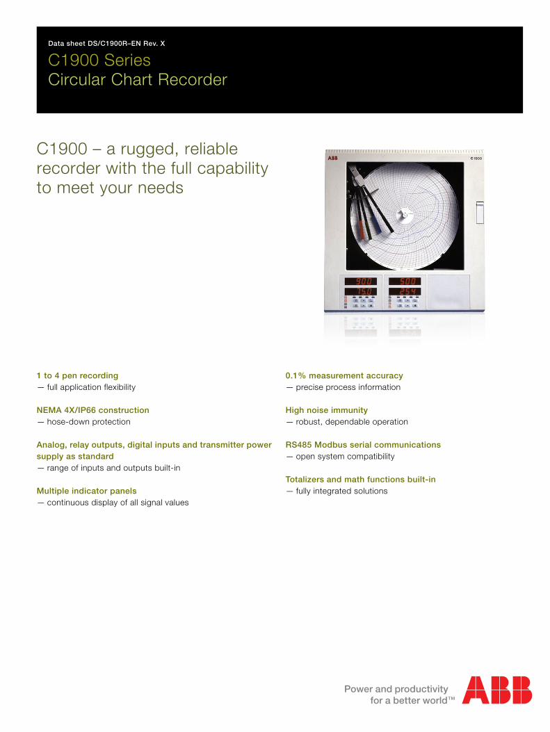
Creto
1 t—
NE—
Ansu—
Mu—
Data sheet DS/C1900R–EN Rev. X
C1900 SeriesCircular Chart Re
1900 – a rugged,
corder with the fcorder
reliable
ull capabilitymeet your needs
o 4 pen recordingfull application flexibility
MA 4X/IP66 constructionhose-down protection
alog, relay outputs, digital inputs and transmitter power pply as standardrange of inputs and outputs built-in
ltiple indicator panelscontinuous display of all signal values
0—
H—
R—
To—
.1% measurement accuracyprecise process information
igh noise immunityrobust, dependable operation
S485 Modbus serial communicationsopen system compatibility
talizers and math functions built-infully integrated solutions

C1900Circular Chart Recorder
C1900The C1900 is a fully programmable circular chart recorder for upto four process signals. The C1900's straightforward operatorcontrols and robust construction make it suitable for a variety ofindustrial environments. Excellent standard facilities arecomplemented by a powerful range of options to give theflexibility to match your application.
Comprehensive Process InformationThe C1900 lets you see the status of your process at a glance:high visibility 6-digit displays provide a clear indication of up tofour process values simultaneously and active alarms aresignalled by flashing LEDs below the main display.
The chart is easily set up to show the information you need inthe way you want. Pen ranges are individually set to give thebest resolution for each signal; the time per revolution can beselected between 1 hour and 32 days. Additionally a true timeevent pen facility enables one pen to be set up as a 3-positionevent marker on the same time line as Pen 1.
Simple Operation
The clearly-labelled tactile keypad gives direct access foroperator adjustments and configuration programming, withoutthe need to open the recorder's door. Clear text prompts on thedigital displays guide the user around the various menus. Apassword-protected security system prevents unauthorizedaccess to configuration adjustment menus.
2 DS/C1900R–EN Rev. X

C1900Circular Chart Recorder
Flexibility to Solve ProblemsThe C1900 offers seamless integration of loop functionality tosolve process problems, eliminating the need for auxiliarydevices.
Totalizers, Math and LogicIntegrating fluid flow to calculate total volume is performed bythe built-in totalizers available for each channel. Relays can beassigned to increment or reset external counters to match therecorder's totalizer values.
User configurable math functions, mass flow calculations andRH tables are all fully supported.
Logic capability allows interlocking and integration of discreteand continuous functions to solve a wide range of processproblems.
Timers and ClockThe C1900 offers two event timers driven by the recorder's real-time clock. The timers can be configured to operate relays,start/stop the chart or trigger other actions within the recorder.
Modbus RS485 CommunicationsCommunications with PCs or PLCs are achieved via the RS485serial communications link, enabling the C1900 to serve as thefront end of plant-wide data acquisition systems. Using ModbusRTU protocol all process inputs and other variables can becontinuously read by a host PC running any of a wide variety ofstandard SCADA packages.
Summation of Three Flows
COMMANDER 1900
Totalizer
Math Equation
Flow A
Flow B
Flow C
A + B + C
Alarm annunciation enabled during night hours only
Timer 1Annunciator
Relay
Logic Equation
ANDChannel 1
Alarm
DS/C1900R–EN Rev. X 3

C1900Circular Chart Recorder
Built to Meet Your NeedsThe C1900's modular architecture gives rise to a high level ofhardware choice: up to five I/O modules can be added to thebasic instrument.
The standard input/output module supplied with every pencomes complete with a fully isolated analog input, a relayoutput, transmitter power supply, isolated analog retransmissionand two digital inputs.
Further input and output capability is provided by a range ofplug-in modules:
Analog input and relay – for use with math functions
Four relays – channel alarm outputs
Eight digital inputs – linked using logic equations
Eight digital outputs – TTL level alarm outputs
Modbus RS485 communications – interfaces with PCs
Expandable for the FutureThe C1900 may be quickly upgraded to meet your changingprocess requirements.
Additional recording channels, math capability or input andoutput functions can be retrofitted on-site using plug-in cardsand easily fitted pen arms. Input calibration data is stored oneach card, allowing quick changes to input cards without theneed for recalibration.
Changes to input sensors or recording procedures areaccommodated by reconfiguration using the main keypad.
Designed to SurviveNEMA 4X protection ensures the C1900 can survive in theharshest environments and makes the recorder ideal for use inpanels which are regularly hosed down. The tough, acid-resistant case and secure cable-entry glands maintain theNEMA 4X rating for wall-mounted or pipe-mounted instruments.
Noise ImmunityRecording accuracy is maintained in noisy industrialenvironments due to the advanced EMC shielding within therecorder. The power supply has been designed to give excellentprotection from power spikes and brownouts and allconfiguration and status information is held in nonvolatilememory to ensure rapid recovery after a power failure.
Minimal MaintenanceExcellent long-term stability keeps recalibration to a minimum,cutting the costs of ownership. User-selectable chart speedsand long-life pens combine to limit usage of consumables.
Built-in QualityThe C1900 is designed, manufactured and tested to the highestquality standards, including ISO 9001.
Easy to InstallA choice of mounting options enables simple installation of therecorder in a panel, on a wall or on a pipe. Detachable terminalblocks allow for trouble-free connection of input and outputwiring, with mains isolation provided by a power switch withinthe instrument.
Wall-mounting
Pipe-mounting
Panel-mounting
4 DS/C1900R–EN Rev. X
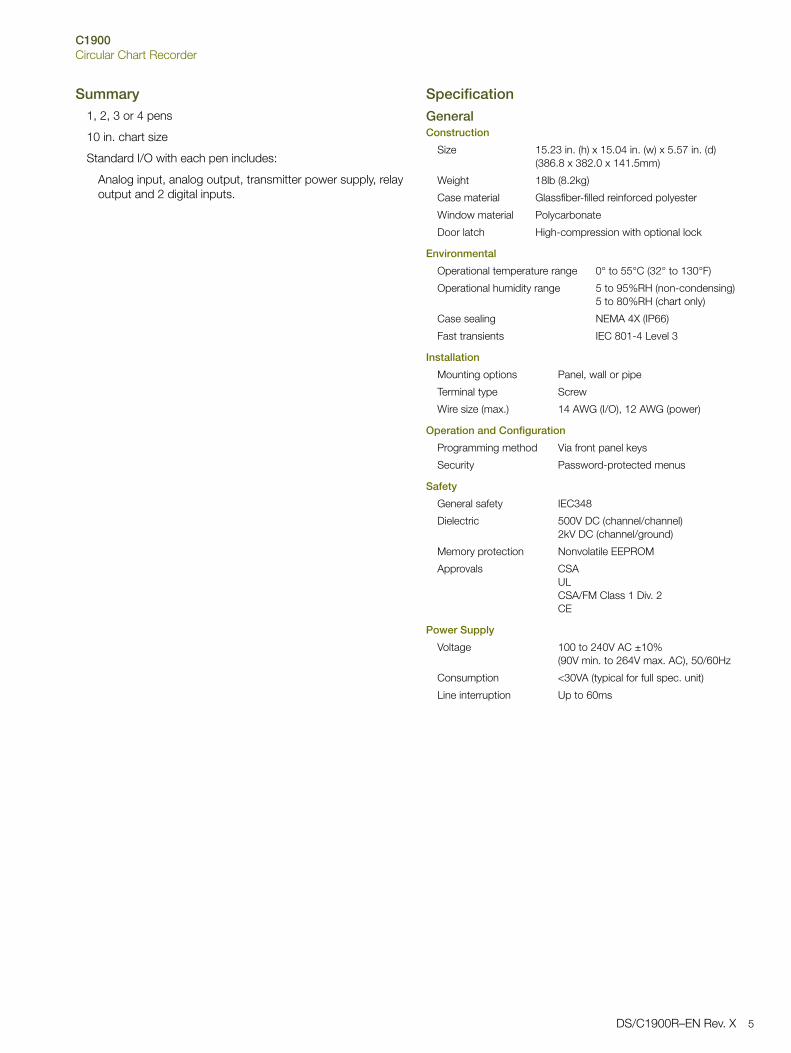
C1900Circular Chart Recorder
Summary1, 2, 3 or 4 pens
10 in. chart size
Standard I/O with each pen includes:
Analog input, analog output, transmitter power supply, relayoutput and 2 digital inputs.
Specification
GeneralConstruction
Environmental
Installation
Operation and Configuration
Safety
Power Supply
Size 15.23 in. (h) x 15.04 in. (w) x 5.57 in. (d)(386.8 x 382.0 x 141.5mm)
Weight 18lb (8.2kg)
Case material Glassfiber-filled reinforced polyester
Window material Polycarbonate
Door latch High-compression with optional lock
Operational temperature range 0° to 55°C (32° to 130°F)
Operational humidity range 5 to 95%RH (non-condensing)5 to 80%RH (chart only)
Case sealing NEMA 4X (IP66)
Fast transients IEC 801-4 Level 3
Mounting options Panel, wall or pipe
Terminal type Screw
Wire size (max.) 14 AWG (I/O), 12 AWG (power)
Programming method Via front panel keys
Security Password-protected menus
General safety IEC348
Dielectric 500V DC (channel/channel)2kV DC (channel/ground)
Memory protection Nonvolatile EEPROM
Approvals CSAULCSA/FM Class 1 Div. 2CE
Voltage 100 to 240V AC ±10%(90V min. to 264V max. AC), 50/60Hz
Consumption <30VA (typical for full spec. unit)
Line interruption Up to 60ms
DS/C1900R–EN Rev. X 5

C1900Circular Chart Recorder
Process Inputs and OutputsGeneral
Analog Inputs
2-Wire Transmitter Power Supply
Analog Outputs
Relay Outputs
Digital Inputs
Digital Outputs
Serial Communications
Analog Input Performance
Noise Rejection Common mode>120dB at 50/60Hz
Normal (series) mode>60dB at 50/60Hz
CJC rejection ratio <0.05°C/°C
Sensor break protection Upscale or downscale drive
Out of range detection 0 to 100% of engineering span
Temperature stability <0.02% of reading/°C or 1µV/°C
Long-term drift <0.01% of reading 10µV annually
Input impedance >10M (mV and V inputs)39 (mA inputs)
Signal types mV, V, mA,
Thermocouple types B, E, J, K, N, R, S, T
Resistance Thermometer Pt100
Other linearizations x1/2, x3/2, x5/2, linear
Sample interval 250ms per channel
Dielectric 500V DC channel/channel
Digital Filter 0 to 60s programmable
Number 1 per channel
Voltage 24V DC nominal
Drive Up to 25mA
Isolation 500V DC channel/channel
Type 4 to 20mA
Accuracy ± 0.1%
Maximum load 750
Dielectric 500V DC
Type SPDT
Rating (with non-inductive load) 5A at 115/230V AC
Type TTL or volt-free
Minimum pulse 250ms
Dielectric 50V DC between modules,no isolation within module
Type 5V TTL
Rating 5mA per output
Dielectric 500V DC between modules,no isolation within module
Connections RS485, 4-wire
Protocol Modbus RTU
Type Range Lo Range Hi Min. Span Accuracy
mV 0 150 5 ±0.1% reading or 10µV
V 0 5 0.1 ±0.1% reading or 20mV
mA 0 50 1 ±0.2% reading or 0.2µA
Ohms (high) 0 750 20 ±0.2% reading or 0.1
Ohms (low) 0 10k 400 ±0.5% reading or 10
°C °F
Type Range Lo Range Hi Range Lo Range Hi Accuracy (excl. CJC)
B –18 1800 0 3270 ± 2 °C (above 200 °C) (3.6 °F above 434 °F)
E –100 900 –140 1650 ± 0.5 °C (± 0.9 °F)
J –100 900 –140 1650 ± 0.5 °C (± 0.9 °F)
K –100 1300 –140 2350 ± 0.5 °C (± 0.9 °F)
N –200 1300 –325 2350 ± 0.5 °C (± 0.9 °F)
R –18 1700 0 3000 ± 1 °C (above 300 °C) (1.8 °F above 572 °F)
S –18 1700 0 3000 ± 1 °C (above 200 °C) 1.8 °F above 572 °F)
T –250 300 –400 550 ± 0.5 °C (± 0.9 °F)
PT100 –200 600 –325 1100 ± 0.5 °C (± 0.9 °F)
6 DS/C1900R–EN Rev. X

C1900Circular Chart Recorder
Recording SystemPens
Event Pens
Chart
Display and Operator PanelsDisplays
Panel keys
Alarms and LogicAlarms
Logic Equations
Advanced Software FunctionsTotalizers
Math
Timers
Option Module*
EMCDesign & Manufacturing Standards
Emissions and ImmunityMeets requirements of:
EN 50081-2EN 50082-2IEC 61326 for an Industrial EnvironmentCE Mark
Option Module Types
Number 1, 2, 3, or 4 (red, blue, green, black)
Response 7 seconds (full scale)
Resolution 0.1% steps
Pen lift Motor-driven, with optional auto-drop
Standard 3-position event recording on any channel
Real time 3-position event recording on the same time line as Pen 1
Chart size 10 in. or 105 mm
Chart speed 1 to 167 hours or 7 to 32 days per revolution
Rotation accuracy <0.5% of rotation time
Number 2 (1 or 2 pens) or 4 (3 or 4 pens)
Type 6-digit red LED, 0.56 in. (14mm) high
Status indicators Indicate channel number on display
Alarm indicators Indicate channels with active alarms
Function Programming access, increment/decrement, pen lift and user-defined function key.
Number 4 per channel
Type High/low process, fast/slow rate of change, time delay
Adjustments Hysteresis, time delay
Number 4
Function OR, AND
Inputs Alarm states, digital inputs, totalizers, logic
Outputs Relays, digital outputs, chart stop, alarm acknowledge
Number 1 per pen
Size 99,999,999 max.
Output External counter driver, 'wrap' pulse signal
Number of equations 4
Type +, –, x, ÷, low & high select, max., min., average, mass flow, RH
Number 2
Type Real-time clock driven event, adjustable duration
Output Relay, digital output, logic equation
Number 5 plus 1 x standard input/output module
Connection Plug-in cards with detachable connection blocks
CSA General Safety Approved
UL General Safety Approved
CSA/FM Class 1 Div. 2 Approved
I/O per module Max. no. per instrumentOption Module Types Analog I/P Analog O/P Trans. PSU Relays Digital I/P Digital O/P Comms.
Standard I/O 1 1 1 1 2 3
Analog I/P + relay 1 1 5
4 relays 4 2
8 digital I/P 8 3
8 digital O/P 8 3
RS485 communications 1 1
1901J (non-upgradeable) 1
DS/C1900R–EN Rev. X 7

C1900Circular Chart Recorder
Ordering InformationPART 1
Accessories
C1900 Recorder 19XX X X X X X X X X X X X XXX
Recorders *
One Pen (Red)Two Pens (Red & Green)Three Pens (Red, Green, Blue)Four Pens (Red, Green, Blue, Black)
11121314
Chart TypeStandard (Recorder/Controller)KPC 105 PX and PXR type chartsChessell Brand charts
JKC
Electrical Code
StandardCSA approvalUL approvalCSA/FM Class 1 Div. 2
ABUF
Option ModuleNoneAdditional Modules – Complete PART 2
0A
OptionsNoneTotalizerTotalizer, Math & Timer
03B
Door LockNot FittedFitted
12
Power Supply
115 V AC230 V AC115 V AC with On/Off Switch230 V AC with On/Off Switch
1245
PART 2 Additional Modules Module Type
Module Position 2 / Channel 2 Input* 0 1 2
Module Position 3 / Channel 3 Input* 0 1 2
Module Position 4 / Channel 4 Input* 0 1 2 3 4 5 6
Module Position 5 0 2 3 4 5
Module Position 6 0 2 4 5 8
Special Settings
Company StandardCustom configuration (customer to complete and supply C1900R custom configuration sheet – INF08/032)SpecialEngineered configuration (customer to supply configuration details required)
STDCUSSXXENG
* Each pen fitted has an associated standard Input/Output module comprising Analog Input, Analog Output, Relay, Transmitter Power Supply and Two Digital Inputs.Additional Input/Output modules may be fitted in the unused Module Positions as required. These additional modules should be specified in PART 2 of the Ordering Information.
Case-to-panel gasket C1900/0149
Wall-mount kit C1900/1712
Pipe-mount kit C1900/0712
Pack of Red Pens C1900/0121
Pack of Green Pens C1900/0122
Pack of Blue Pens C1900/0120
Pack of Black Pens C1900/0119
Pack of Purple Pens C1900/0123
After-sales Engineered Configuration Service ENG/REC
8 DS/C1900R–EN Rev. X

C1900Circular Chart Recorder
Key to Module Types
0 No module fitted / Pen input channel *
1 Standard Input/Output
2 Analog Input (Math Input) + Relay
3 Four Relays
4 Eight Digital Inputs
5 Eight Digital Outputs
6 True Time Event Pen (Violet)
8 Modbus RS485 Communications
* On 2, 3 or 4 pen instruments a standard I/O module is alwaysfitted in the corresponding module position (enter '0' in thecorresponding order code field).
Module Positions
1 2 3 4 5 6Example. 1 9 1 3 J A A 0 1 1 0 0 3 0 8 STD
3 pens
4 relays
Modbus RS485 Communications
DS/C1900R–EN Rev. X 9
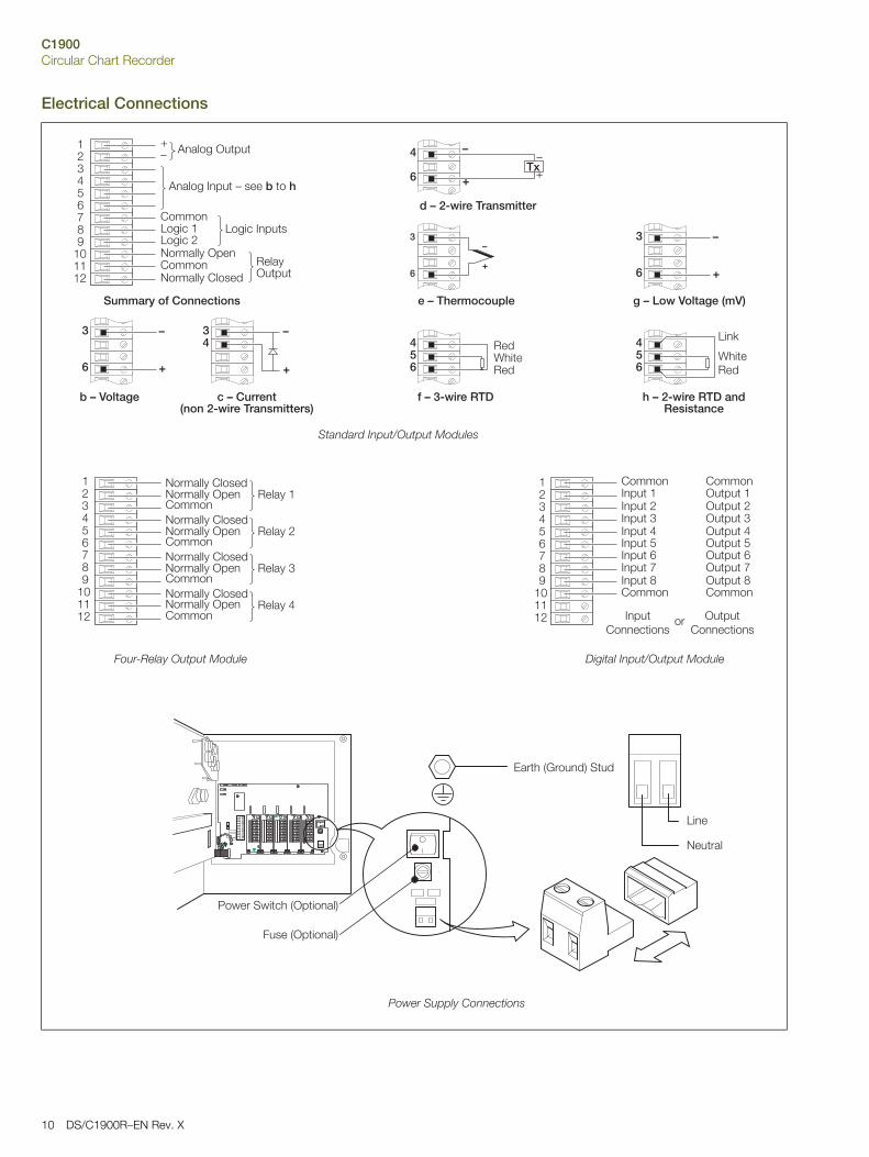
C1900Circular Chart Recorder
Electrical Connections
10 DS/C1900R–EN Rev. X
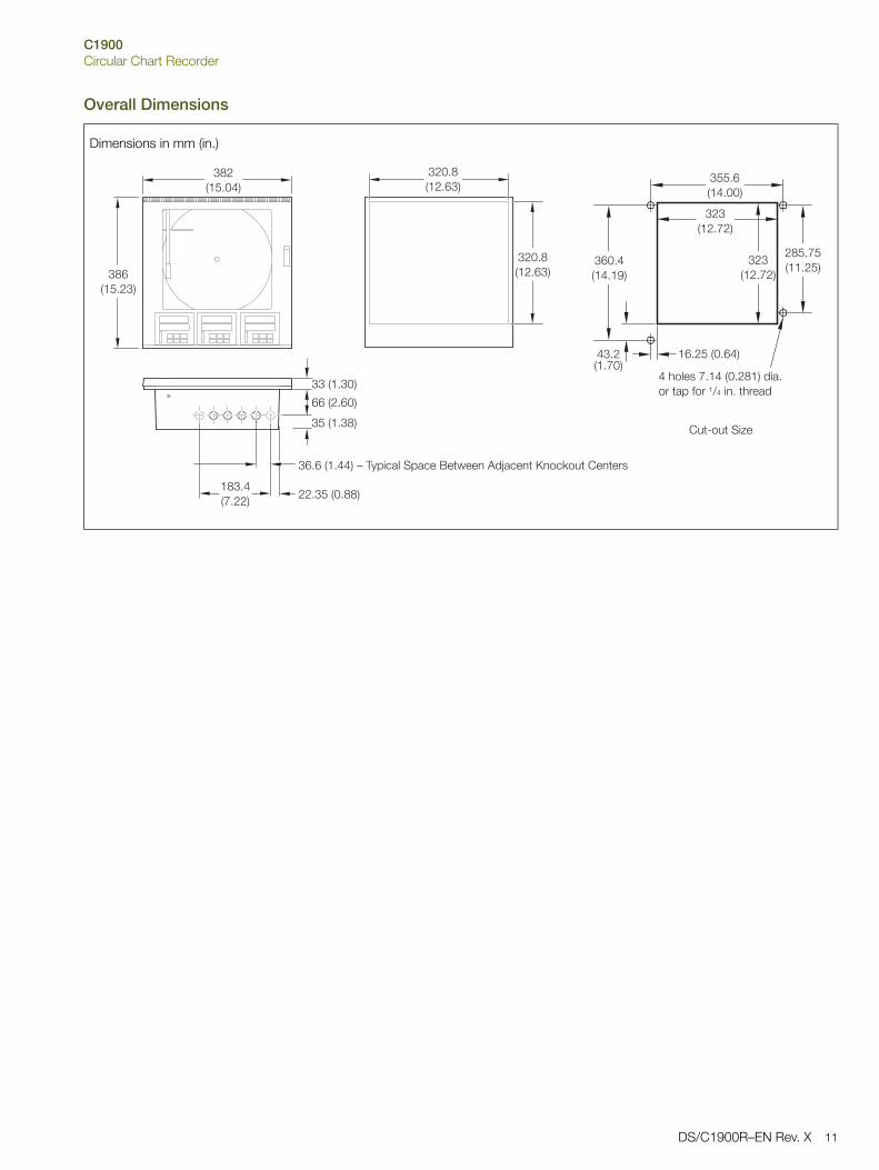
C1900Circular Chart Recorder
Overall Dimensions
Dimensions in mm (in.)
DS/C1900R–EN Rev. X 11

Contact us
DS
/C19
00R
–EN
Rev
. X02
.201
4
ABB LimitedProcess AutomationHoward RoadSt. NeotsCambridgeshire PE19 8EUUKTel: +44 (0)1480 475321Fax: +44 (0)1480 217948ABB Inc.Process Automation125 E. County Line RoadWarminsterPA 18974USATel: +1 215 674 6000Fax: +1 215 674 7183
www.abb.com/recorders
NoteWe reserve the right to make technical changes or modify the contents of this document without prior notice. With regard to purchase orders, the agreed particulars shall prevail. ABB does not accept any responsibility whatsoever for potential errors or possible lack of information in this document.
We reserve all rights in this document and in the subject matter and illustrations contained therein. Any reproduction, disclosure to third parties or utilization of its contents in whole or in parts – is forbidden without prior written consent of ABB.
Copyright© 2014 ABB
All rights reserved3KXR200103R1001
Sales
Service
Software