abb capacitor
DESCRIPTION
CATALOGUETRANSCRIPT
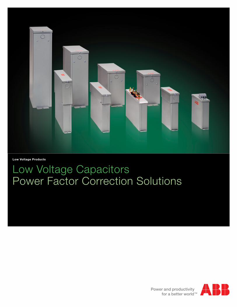
Low Voltage CapacitorsPower Factor Correction Solutions
Low Voltage Products
2 Reliability for Power Factor Correction | Low Voltage Capacitors
Dry type designThe ABB Low Voltage Capacitors, called CLMD, use dry type dielectric and therefore avoid any risk of leakage or pollution in the environment.
Very low lossesDielectric losses are less than 0.2 Watt per kvar. Total losses, including discharge resistors, are less than 0.5 Watt per kvar.
Long life - Self-healingIn the event of a fault developing in the capacitor’s dielectric, the metalized electrode adjacent to the fault is immediately va-porized, thus insulating the fault. The capacitor then continues normal operation.
Fire protectionAll elements within the CLMD capacitor are surrounded by vermiculite which is an inorganic, inert, fire proof and non toxic granular material. In the event of any failure the vermiculite absorbs safely the energy produced within the capacitor box and extinguishes any possible flames.
Unique protection systemA unique Sequential Protection System ensures that each individual element can be disconnected from the circuit at the end of its life.
Easy to install - light weightThe CLMD capacitor light weight makes it easy to handle and install.
High reliabilityThe use of robust terminals removes the risk of damage during installation and reduces maintenance requirements.
SecurityThermal equalizers are fitted to surround each capacitor element and provide effective heat dissipation. The CLMD capacitor is equipped with discharge resistors.
ISO 9001Our ISO 9001 Quality System registration provides the strongest assurance of our product quality.
ISO 14001The CLMD capacitor has a dry type dielectric and is free from liquids or other impregnating agents. It has been designed for environmentally friendly manufacturing. Our ISO 14001 certification guarantees our commitment to the environment.
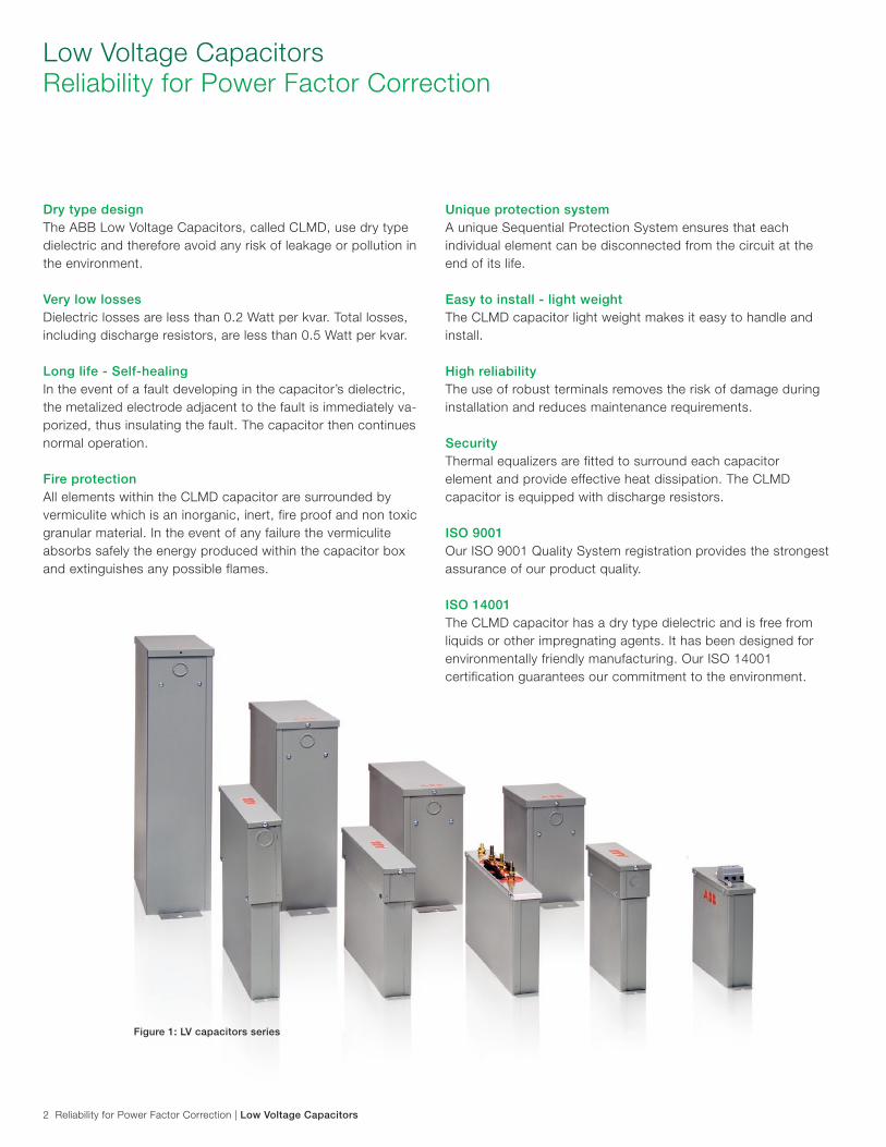
Low Voltage CapacitorsReliability for Power Factor Correction
Figure 1: LV capacitors series
Low Voltage Capacitors | Construction 3
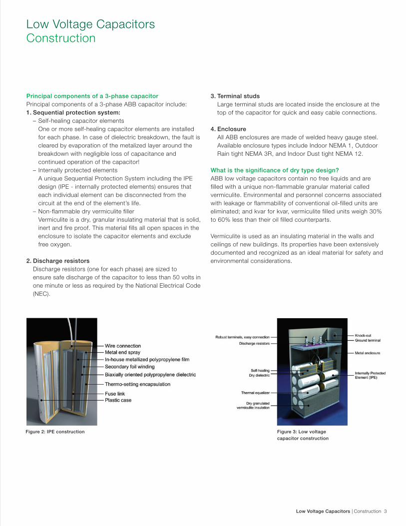
Principal components of a 3-phase capacitor Principal components of a 3-phase ABB capacitor include: 1. Sequential protection system: – Self-healing capacitor elements One or more self-healing capacitor elements are installed for each phase. In case of dielectric breakdown, the fault is cleared by evaporation of the metalized layer around the breakdown with negligible loss of capacitance and continued operation of the capacitor! – Internally protected elements A unique Sequential Protection System including the IPE design (IPE - internally protected elements) ensures that each individual element can be disconnected from the circuit at the end of the element’s life. – Non-flammable dry vermiculite filler Vermiculite is a dry, granular insulating material that is solid, inert and fire proof. This material fills all open spaces in the enclosure to isolate the capacitor elements and exclude free oxygen.
2. Discharge resistors Discharge resistors (one for each phase) are sized to ensure safe discharge of the capacitor to less than 50 volts in one minute or less as required by the National Electrical Code (NEC).
3. Terminal studs Large terminal studs are located inside the enclosure at the top of the capacitor for quick and easy cable connections.
4. Enclosure All ABB enclosures are made of welded heavy gauge steel. Available enclosure types include Indoor NEMA 1, Outdoor Rain tight NEMA 3R, and Indoor Dust tight NEMA 12.
What is the significance of dry type design? ABB low voltage capacitors contain no free liquids and are filled with a unique non-flammable granular material called vermiculite. Environmental and personnel concerns associated with leakage or flammability of conventional oil-filled units are eliminated; and kvar for kvar, vermiculite filled units weigh 30% to 60% less than their oil filled counterparts.
Vermiculite is used as an insulating material in the walls and ceilings of new buildings. Its properties have been extensively documented and recognized as an ideal material for safety and environmental considerations.
Low Voltage Capacitors Construction
Figure 2: IPE construction Figure 3: Low voltage capacitor construction
4 Construction | Low Voltage Capacitors
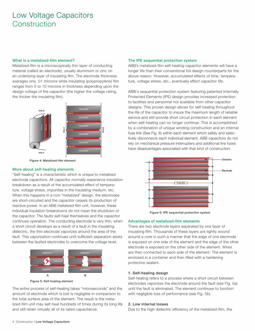
What is a metalized-film element? Metalized-film is a microscopically thin layer of conducting material (called an electrode), usually aluminium or zinc on an underlying layer of insulating film. The electrode thickness averages only .01 microns while insulating (polypropylene) film ranges from 5 to 10 microns in thickness depending upon the design voltage of the capacitor (the higher the voltage rating, the thicker the insulating film).
More about self-healing elements “Self-healing” is a characteristic which is unique to metalized electrode capacitors. All capacitor normally experience insulation breakdown as a result of the accumulated effect of tempera-ture, voltage stress, impurities in the insulating medium, etc. When this happens in a non-“metalized“ design, the electrodes are short-circuited and the capacitor ceases its production of reactive power. In an ABB metalized-film unit, however, these individual insulation breakdowns do not mean the shutdown of the capacitor. The faults self-heal themselves and the capacitor continues operation. The conducting electrode is very thin; when a short circuit develops as a result of a fault in the insulating dielectric, the thin electrode vaporizes around the area of the fault. This vaporization continues until sufficient separation exists between the faulted electrodes to overcome the voltage level.
The entire process of self-healing takes “microseconds” and the amount of electrode which is lost is negligible in comparison to the total surface area of the element. The result is the meta-lized-film unit may self-heal hundreds of times during its long life and still retain virtually all of its rated capacitance.
The IPE sequential protection systemABB’s metalized-film self-healing capacitor elements will have a longer life than their conventional foil design counterparts for the above reason. However, accumulated effects of time, tempera-ture, voltage stress, etc., eventually effect capacitor life.
ABB‘s sequential protection system featuring patented Internally Protected Elements (IPE) design provides increased protection to facilities and personnel not available from other capacitor designs. This proven design allows for self-healing throughout the life of the capacitor to insure the maximum length of reliable service and still provide short circuit protection in each element when self-healing can no longer continue. This is accomplished by a combination of unique winding construction and an internal fuse link (See Fig. 6) within each element which safely and selec-tively disconnects each individual element. ABB capacitors do not rely on mechanical pressure interrupters and additional line fuses have disadvantages associated with that kind of construction.
Advantages of metalized-film elements There are two electrode layers separated by one layer of insulating film. Thousands of these layers are tightly wound around a core in such a manner that the edge of one electrode is exposed on one side of the element and the edge of the other electrode is exposed on the other side of the element. Wires are then connected to each side of the element. The element is enclosed in a container and then filled with a hardening protective sealant.
1. Self-healing design Self-healing refers to a process where a short circuit between electrodes vaporizes the electrode around the fault (see Fig. 5a) until the fault is eliminated. The element continues to function with negligible loss of performance (see Fig. 5b).
2. Low internal losses Due to the high dielectric efficiency of the metalized-film, the
Low Voltage Capacitors Construction
Figure 4: Metalized-film element
A B
Figure 5: Self-healing element
Figure 6: IPE sequential protection system
Low Voltage Capacitors | Construction 5
internal losses are extremely low. ABB metalized-film design losses are limited to .5 watts per kvar including the losses across the discharge resistors.
3. Small element size Due to the thin electrode and dielectric, metalized-film elements are small and compact in size resulting in smaller, more power-ful capacitors.
The capacitance of any element design is inversely proportional to the separation between electrodes. In other words, if theseparation between conducting surfaces is cut in half, the
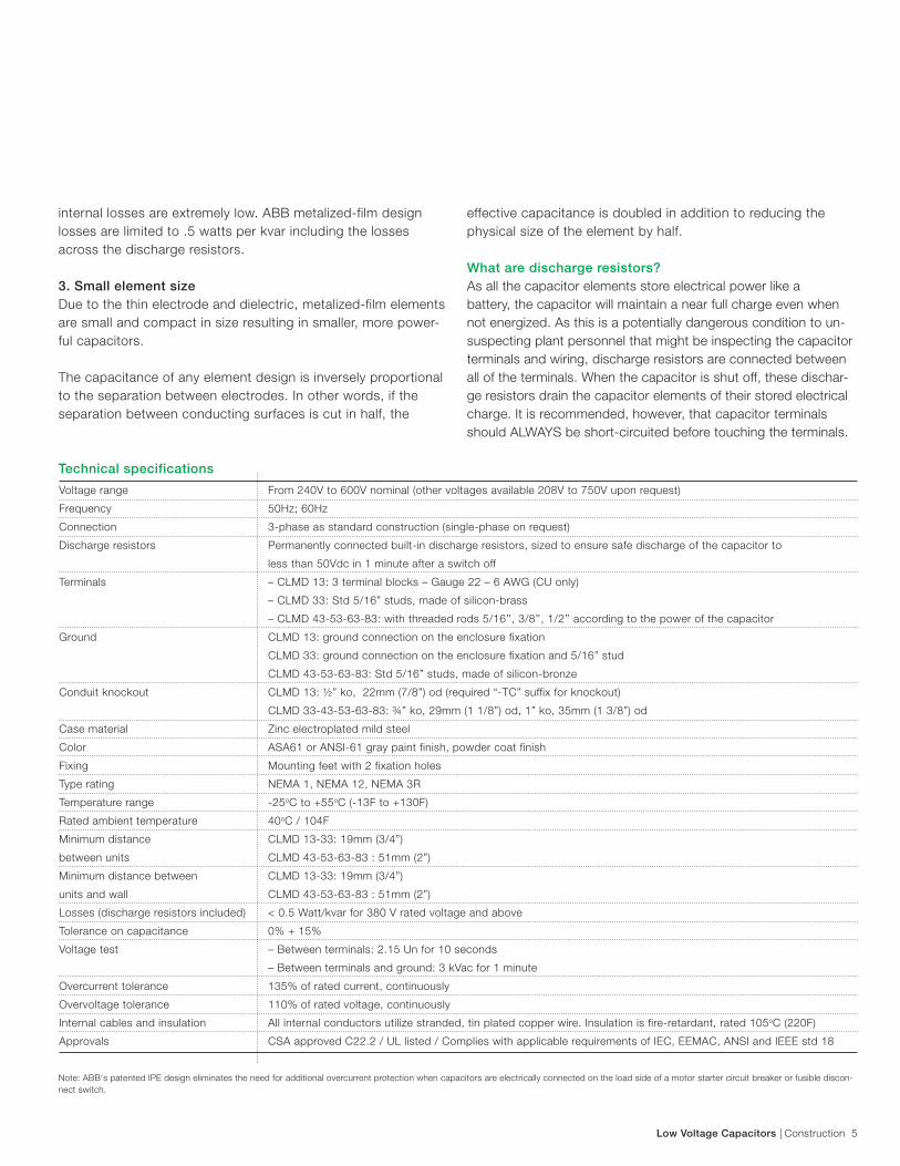
Technical specifications
effective capacitance is doubled in addition to reducing the physical size of the element by half.
What are discharge resistors? As all the capacitor elements store electrical power like a battery, the capacitor will maintain a near full charge even when not energized. As this is a potentially dangerous condition to un-suspecting plant personnel that might be inspecting the capacitor terminals and wiring, discharge resistors are connected between all of the terminals. When the capacitor is shut off, these dischar-ge resistors drain the capacitor elements of their stored electrical charge. It is recommended, however, that capacitor terminals should ALWAYS be short-circuited before touching the terminals.
Voltage range From 240V to 600V nominal (other voltages available 208V to 750V upon request)
Frequency 50Hz; 60Hz
Connection 3-phase as standard construction (single-phase on request)
Discharge resistors Permanently connected built-in discharge resistors, sized to ensure safe discharge of the capacitor to
less than 50Vdc in 1 minute after a switch off
Terminals – CLMD 13: 3 terminal blocks – Gauge 22 – 6 AWG (CU only)
– CLMD 33: Std 5/16” studs, made of silicon-brass
– CLMD 43-53-63-83: with threaded rods 5/16’’, 3/8’’, 1/2’’ according to the power of the capacitor
Ground CLMD 13: ground connection on the enclosure fixation
CLMD 33: ground connection on the enclosure fixation and 5/16” stud
CLMD 43-53-63-83: Std 5/16” studs, made of silicon-bronze
Conduit knockout CLMD 13: ½” ko, 22mm (7/8”) od (required “-TC” suffix for knockout)
CLMD 33-43-53-63-83: ¾” ko, 29mm (1 1/8”) od, 1” ko, 35mm (1 3/8”) od
Case material Zinc electroplated mild steel
Color ASA61 or ANSI-61 gray paint finish, powder coat finish
Fixing Mounting feet with 2 fixation holes
Type rating NEMA 1, NEMA 12, NEMA 3R
Temperature range -25oC to +55oC (-13F to +130F)
Rated ambient temperature 40oC / 104F
Minimum distance CLMD 13-33: 19mm (3/4”)
between units CLMD 43-53-63-83 : 51mm (2”)
Minimum distance between CLMD 13-33: 19mm (3/4”)
units and wall CLMD 43-53-63-83 : 51mm (2”)
Losses (discharge resistors included) < 0.5 Watt/kvar for 380 V rated voltage and above
Tolerance on capacitance 0% + 15%
Voltage test – Between terminals: 2.15 Un for 10 seconds
– Between terminals and ground: 3 kVac for 1 minute
Overcurrent tolerance 135% of rated current, continuously
Overvoltage tolerance 110% of rated voltage, continuously
Internal cables and insulation All internal conductors utilize stranded, tin plated copper wire. Insulation is fire-retardant, rated 105oC (220F)
Approvals CSA approved C22.2 / UL listed / Complies with applicable requirements of IEC, EEMAC, ANSI and IEEE std 18
Note: ABB‘s patented IPE design eliminates the need for additional overcurrent protection when capacitors are electrically connected on the load side of a motor starter circuit breaker or fusible discon-nect switch.
6 Ordering Information | Low Voltage Capacitors
Ordering Information
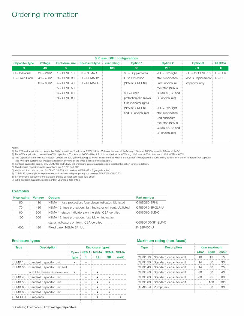
Notes:1) For 208 volt applications, derate the 240V capacitors. The kvar at 208V will be .75 times the kvar at 240V. e.g. 15kvar at 208V is equal to 20kvar at 240V.2) For 660V application, derate the 600V capacitors. The kvar at 660V will be 1.211 times the kvar at 600V. e.g. 100 kvar at 600V is equal to 120 KVAR at 660V.3) The capacitor state indication system consists of two yellow LED lights which illuminate only when the capacitor is energized and functioning at 65% or more of its rated kvar capacity. The two light systems will indicate a failure in any one of the three phases of the capacitor.4) For fixed capacitor banks, only CLMD 63 and CLMD 83 enclosure size are available (see fixed bank section for more details).5) Fixed banks capacitor available options are 3F, 3FI and 2LF. 6) Wall mount kit can be used for CLMD 13-83 (part number WM83-KIT – 6 gauge bracket). 7) CLMD 33 open style for replacement unit requires adapter plate (part number ADAPTER CLMD 33). 8) Single phase capacitors are available, please contact your local field office.9) 50Hz option is available, please contact your local field office.
Kvar rating Voltage Options Part number
50 480 NEMA 1, fuse protection, fuse blown indicator, UL listed C485G50-3FI-U
75 480 NEMA 12, fuse protection, light Indicator on front, UL listed C486D75-3F-2LF-U
80 600 NEMA 1, status Indicators on the side, CSA certified C606G60-2LE-C
100 600 NEMA 12, fuse protection, fuse blown indication,
status indicators on front, CSA certified C608D100-3FI-2LF-C
400 480 Fixed bank, NEMA 3R, UL F488R400-U
Examples
Enclosure types
Type Description Enclosure types
Open NEMA NEMA NEMA NEMA
type 1 12 3R 4-4X
CLMD13 Standardcapacitorunit • •
CLMD 33 Standard capacitor unit and
with HRC fuses (Stud mounted) • • •
CLMD43 Standardcapacitorunit • • •
CLMD53 Standardcapacitorunit • • •
CLMD63 Standardcapacitorunit • • •
CLMD83 Standardcapacitorunit • • •
CLMD-PJ PumpJack • • • •
Capacitor type Voltage Enclosure size Enclosure type kvar rating Option 1 Option 2 Option 3 UL/CSA
C 48 8 G 100 3F 2LF - O U
C = Individual 24 = 240V 1 = CLMD 13 G = NEMA 1 3F = Supplemental 2LF = Two-light - O = for CLMD 13 C = CSA
F = Fixed Bank 48 = 480V 3 = CLMD 33 D = NEMA 12 Fuse Protection status indication, and 33 replacement U = UL
60 = 600V 4 = CLMD 43 R = NEMA 3R (N/A in CLMD 13) Front enclosure capacitor only
5 = CLMD 53 mounted (N/A in
6 = CLMD 63 3FI = Fuses CLMD 13, 33 and
8 = CLMD 83 protection and blown 3R enclosures)
fuse indicator lights
(N/A in CLMD 13 2LE = Two-light
and 3R enclosures) status indication,
End enclosure
mounted (N/A in
CLMD 13, 33 and
3R enclosures)
3 Phase, 60Hz configurations
Maximum rating (non-fused)
Type Description Kvar maximum
240V 480V 600V
CLMD 13 Standard capacitor unit 10 15 15
CLMD 33 Standard capacitor unit 14 30 30
CLMD 43 Standard capacitor unit 14 30 25
CLMD 53 Standard capacitor unit 30 50 40
CLMD 63 Standard capacitor unit 60 75 80
CLMD 83 Standard capacitor unit - 100 100
CLMD-PJ Pump Jack - 30 30
Low Voltage Capacitors | Ordering Part Numbers 7
Ordering Part Numbers
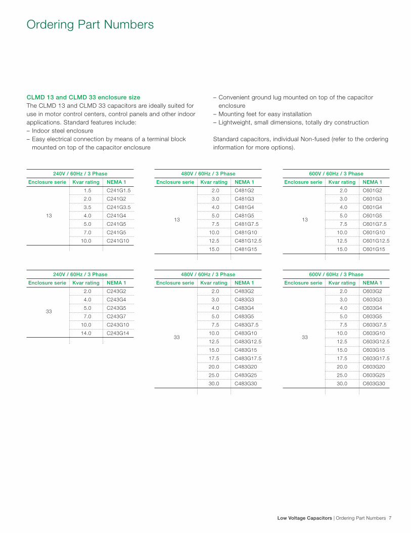
CLMD 13 and CLMD 33 enclosure size The CLMD 13 and CLMD 33 capacitors are ideally suited for use in motor control centers, control panels and other indoor applications. Standard features include: – Indoor steel enclosure – Easy electrical connection by means of a terminal block mounted on top of the capacitor enclosure
– Convenient ground lug mounted on top of the capacitor enclosure – Mounting feet for easy installation – Lightweight, small dimensions, totally dry construction
Standard capacitors, individual Non-fused (refer to the ordering information for more options).
240V / 60Hz / 3 Phase
Enclosure serie Kvar rating NEMA 1
1.5 C241G1.5
2.0 C241G2
3.5 C241G3.5
13 4.0 C241G4
5.0 C241G5
7.0 C241G5
10.0 C241G10
600V / 60Hz / 3 Phase
Enclosure serie Kvar rating NEMA 1
2.0 C601G2
3.0 C601G3
4.0 C601G4
13
5.0 C601G5
7.5 C601G7.5
10.0 C601G10
12.5 C601G12.5
15.0 C601G15
480V / 60Hz / 3 Phase
Enclosure serie Kvar rating NEMA 1
2.0 C483G2
3.0 C483G3
4.0 C483G4
5.0 C483G5
7.5 C483G7.5
33
10.0 C483G10
12.5 C483G12.5
15.0 C483G15
17.5 C483G17.5
20.0 C483G20
25.0 C483G25
30.0 C483G30
480V / 60Hz / 3 Phase
Enclosure serie Kvar rating NEMA 1
2.0 C481G2
3.0 C481G3
4.0 C481G4
13
5.0 C481G5
7.5 C481G7.5
10.0 C481G10
12.5 C481G12.5
15.0 C481G15
600V / 60Hz / 3 Phase
Enclosure serie Kvar rating NEMA 1
2.0 C603G2
3.0 C603G3
4.0 C603G4
5.0 C603G5
7.5 C603G7.5
33
10.0 C603G10
12.5 C603G12.5
15.0 C603G15
17.5 C603G17.5
20.0 C603G20
25.0 C603G25
30.0 C603G30
240V / 60Hz / 3 Phase
Enclosure serie Kvar rating NEMA 1
2.0 C243G2
4.0 C243G4
33
5.0 C243G5
7.0 C243G7
10.0 C243G10
14.0 C243G14
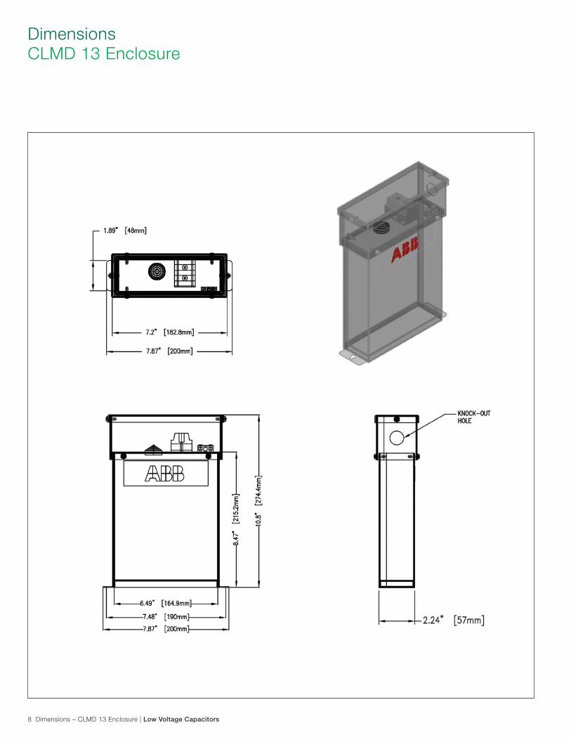
8 Dimensions – CLMD 13 Enclosure | Low Voltage Capacitors
Dimensions CLMD 13 Enclosure
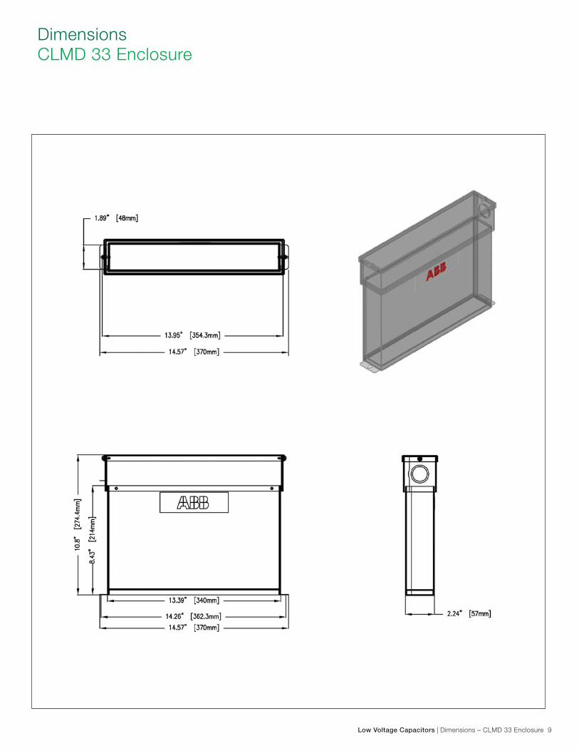
Low Voltage Capacitors | Dimensions – CLMD 33 Enclosure 9
Dimensions CLMD 33 Enclosure
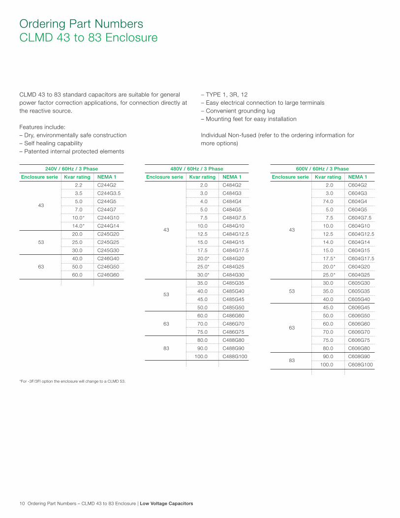
10 Ordering Part Numbers – CLMD 43 to 83 Enclosure | Low Voltage Capacitors
Ordering Part Numbers CLMD 43 to 83 Enclosure
CLMD 43 to 83 standard capacitors are suitable for general power factor correction applications, for connection directly at the reactive source.
Features include:– Dry, environmentally safe construction– Self healing capability– Patented internal protected elements
– TYPE 1, 3R, 12– Easy electrical connection to large terminals– Convenient grounding lug– Mounting feet for easy installation
Individual Non-fused (refer to the ordering information for more options)
240V / 60Hz / 3 Phase
Enclosure serie Kvar rating NEMA 1
2.2 C244G2
3.5 C244G3.5
43
5.0 C244G5
7.0 C244G7
10.0 C244G10
14.0 C244G14
20.0 C245G20
53 25.0 C245G25
30.0 C245G30
40.0 C246G40
63 50.0 C246G50
60.0 C246G60
*
*
480V / 60Hz / 3 Phase
Enclosure serie Kvar rating NEMA 1
2.0 C484G2
3.0 C484G3
4.0 C484G4
5.0 C484G5
7.5 C484G7.5
43
10.0 C484G10
12.5 C484G12.5
15.0 C484G15
17.5 C484G17.5
20.0 C484G20
25.0 C484G25
30.0 C484G30
35.0 C485G35
53
40.0 C485G40
45.0 C485G45
50.0 C485G50
60.0 C486G60
63 70.0 C486G70
75.0 C486G75
80.0 C488G80
83 90.0 C488G90
100.0 C488G100
*
*
*
600V / 60Hz / 3 Phase
Enclosure serie Kvar rating NEMA 1
2.0 C604G2
3.0 C604G3
74.0 C604G4
5.0 C604G5
7.5 C604G7.5
43
10.0 C604G10
12.5 C604G12.5
14.0 C604G14
15.0 C604G15
17.5 C604G17.5
20.0 C604G20
25.0 C604G25
30.0 C605G30
53 35.0 C605G35
40.0 C605G40
45.0 C606G45
50.0 C606G50
63
60.0 C606G60
70.0 C606G70
75.0 C606G75
80.0 C606G80
83
90.0 C608G90
100.0 C608G100
*
*
*
*For -3F/3FI option the enclosure will change to a CLMD 53.
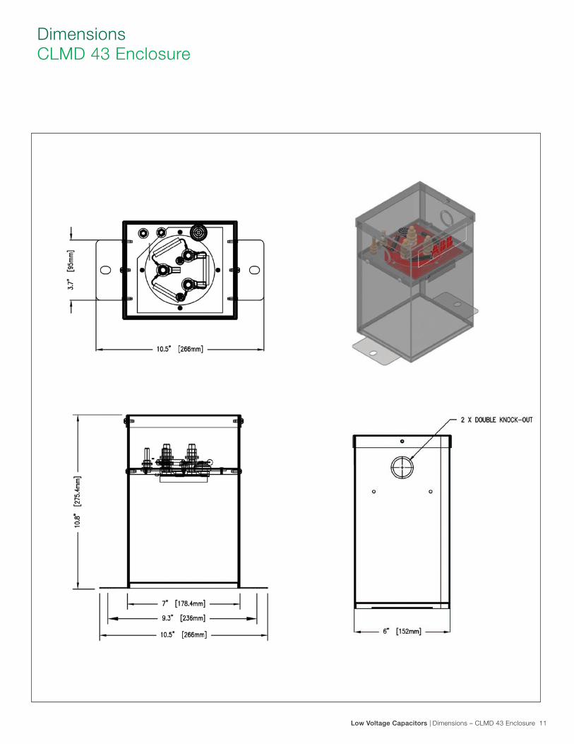
Low Voltage Capacitors | Dimensions – CLMD 43 Enclosure 11
Dimensions CLMD 43 Enclosure
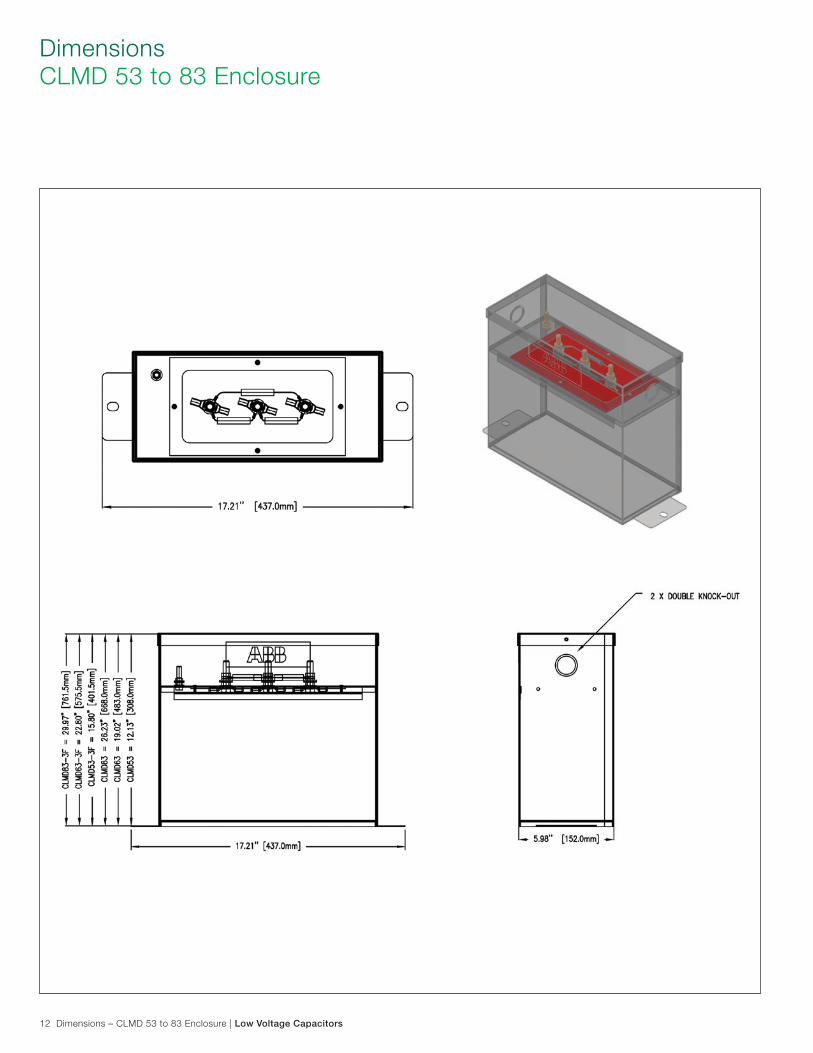
12 Dimensions – CLMD 53 to 83 Enclosure | Low Voltage Capacitors
Dimensions CLMD 53 to 83 Enclosure
Low Voltage Capacitors | Dimensions – CLMD 53 to 83 3R Enclosure 13
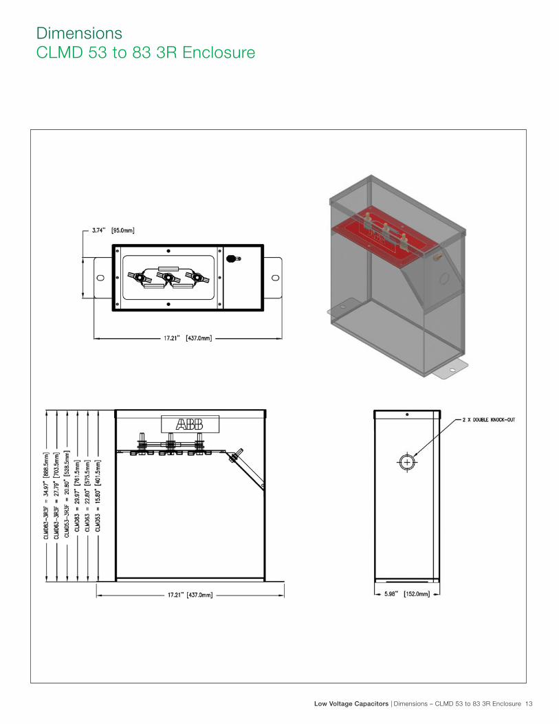
Dimensions CLMD 53 to 83 3R Enclosure
14 Pump Jack Capacitor | Low Voltage Capacitors
Pump Jack Capacitor
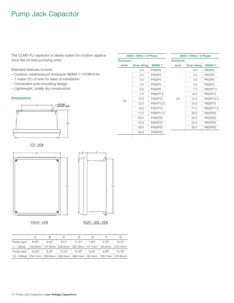
The CLMD-PJ capacitor is ideally suited for outdoor applica-tions like oil-field pumping units.
Standard features include: – Outdoor, weatherproof enclosure NEMA 1/12/3R/4/4x– 1 meter (3’) of wire for ease of installation – Convenient pole-mounting design – Lightweight, totally dry construction
Dimensions
A B C D E F G
Pump Jack 6.05” 5.43” 9.31” 11.31” 1.62” 3.75” 10.72”
1 – 15kvar 152.8mm 137.9mm 236.5mm 287.3mm 41.1mm 95.2mm 272.3mm
Pump Jack 10.00” 8.26” 13.32” 15.32” 3.24” 4.99” 14.76”
16 – 30kvar 254.1mm 209.8mm 338.3mm 389.1mm 82.4mm 126.7mm 374.8mm
480V / 60Hz / 3 Phase
Enclosure
serie Kvar rating NEMA 1
2.0 P482P2
3.0 P482P3
4.0 P482P4
5.0 P482P5
6.0 P482P6
7.5 P482P7.5
23
10.0 P482P10
12.5 P481P12.5
15.0 P481P15
17.5 P482P17.5
20.0 P482P20
22.0 P482P22
25.0 P482P25
30.0 P482P30
600V / 60Hz / 3 Phase
Enclosure
serie Kvar rating NEMA 1
2.0 P602P2
3.0 P602P3
4.0 P602P4
5.0 P602P5
7.5 P602P7.5
10.0 P602P10
23 12.5 P602P12.5
15.0 P602P15
17.5 P602P17.5
20.0 P602P20
22.0 P602P22
25.0 P602P25
30.0 P602P30
Low Voltage Capacitors | Fixed Capacitor Bank 15
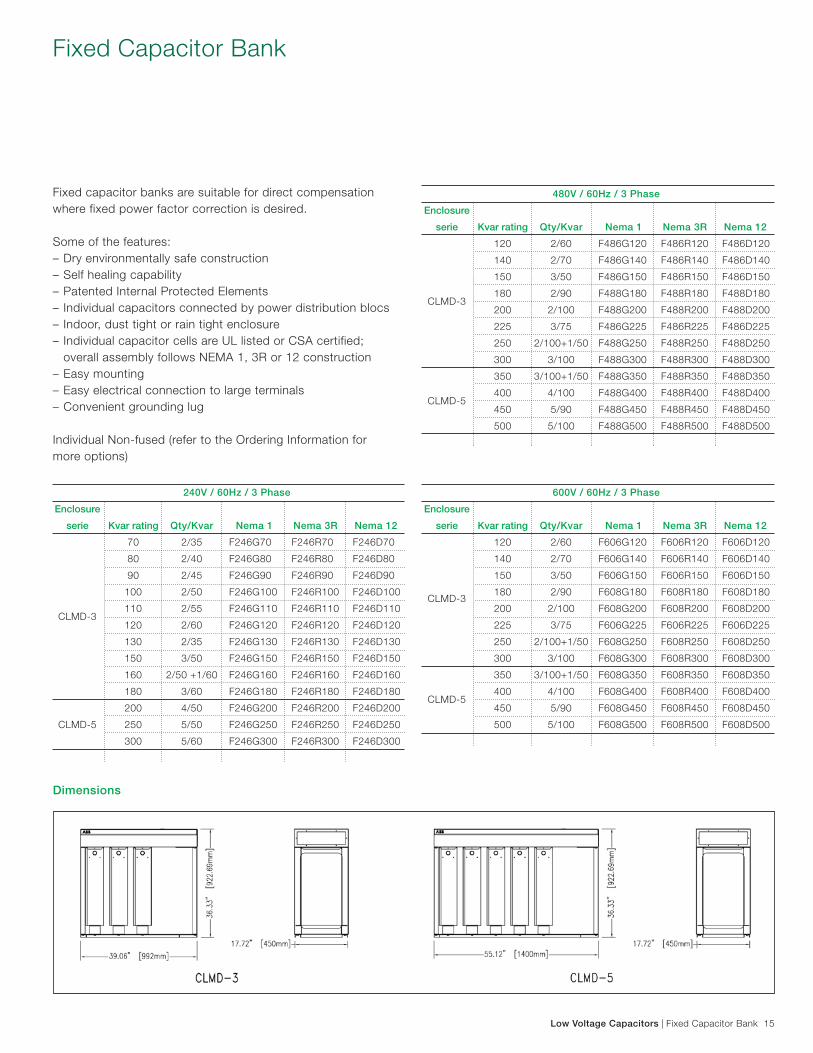
Fixed Capacitor Bank
Fixed capacitor banks are suitable for direct compensation where fixed power factor correction is desired.
Some of the features: – Dry environmentally safe construction– Self healing capability– Patented Internal Protected Elements– Individual capacitors connected by power distribution blocs– Indoor, dust tight or rain tight enclosure– Individual capacitor cells are UL listed or CSA certified; overall assembly follows NEMA 1, 3R or 12 construction– Easy mounting– Easy electrical connection to large terminals– Convenient grounding lug
Individual Non-fused (refer to the Ordering Information for more options)
240V / 60Hz / 3 Phase
Enclosure
serie Kvar rating Qty/Kvar Nema 1 Nema 3R Nema 12
70 2/35 F246G70 F246R70 F246D70
80 2/40 F246G80 F246R80 F246D80
90 2/45 F246G90 F246R90 F246D90
100 2/50 F246G100 F246R100 F246D100
CLMD-3
110 2/55 F246G110 F246R110 F246D110
120 2/60 F246G120 F246R120 F246D120
130 2/35 F246G130 F246R130 F246D130
150 3/50 F246G150 F246R150 F246D150
160 2/50 +1/60 F246G160 F246R160 F246D160
180 3/60 F246G180 F246R180 F246D180
200 4/50 F246G200 F246R200 F246D200
CLMD-5 250 5/50 F246G250 F246R250 F246D250
300 5/60 F246G300 F246R300 F246D300
600V / 60Hz / 3 Phase
Enclosure
serie Kvar rating Qty/Kvar Nema 1 Nema 3R Nema 12
120 2/60 F606G120 F606R120 F606D120
140 2/70 F606G140 F606R140 F606D140
150 3/50 F606G150 F606R150 F606D150
CLMD-3
180 2/90 F608G180 F608R180 F608D180
200 2/100 F608G200 F608R200 F608D200
225 3/75 F606G225 F606R225 F606D225
250 2/100+1/50 F608G250 F608R250 F608D250
300 3/100 F608G300 F608R300 F608D300
350 3/100+1/50 F608G350 F608R350 F608D350
CLMD-5
400 4/100 F608G400 F608R400 F608D400
450 5/90 F608G450 F608R450 F608D450
500 5/100 F608G500 F608R500 F608D500
480V / 60Hz / 3 Phase
Enclosure
serie Kvar rating Qty/Kvar Nema 1 Nema 3R Nema 12
120 2/60 F486G120 F486R120 F486D120
140 2/70 F486G140 F486R140 F486D140
150 3/50 F486G150 F486R150 F486D150
CLMD-3
180 2/90 F488G180 F488R180 F488D180
200 2/100 F488G200 F488R200 F488D200
225 3/75 F486G225 F486R225 F486D225
250 2/100+1/50 F488G250 F488R250 F488D250
300 3/100 F488G300 F488R300 F488D300
350 3/100+1/50 F488G350 F488R350 F488D350
CLMD-5
400 4/100 F488G400 F488R400 F488D400
450 5/90 F488G450 F488R450 F488D450
500 5/100 F488G500 F488R500 F488D500
Dimensions
16 Sizing Low Voltage Capacitors at the Motor Load | Low Voltage Capacitors
Sizing capacitors at the motor loadWhen the determination is made that power factor correctioncapacitors ARE a good investment for a particular electricalsystem, you need to know:– How many capacitors are needed?– What sizes are appropriate? The capacitor provides a local source of reactive current.With respect to inductive motor load, this reactive power is the magnetizing or “no-load current“ which the motor requires to operate.
A capacitor is properly sized when its full load current ratingis 90% of the no-load current of the motor. This 90% ratingavoids overcorrection and the accompanying problems suchas overvoltages.
One selection method: Using formulas.If no-load current is known...The most accurate method of selecting a capacitor is to takethe no-load current of the motor, and multiply by .90 (90%).Take this resulting figure, turn to the appropriate catalog page, and determine which kvar size is needed, catalog number, enclosure type, and price.
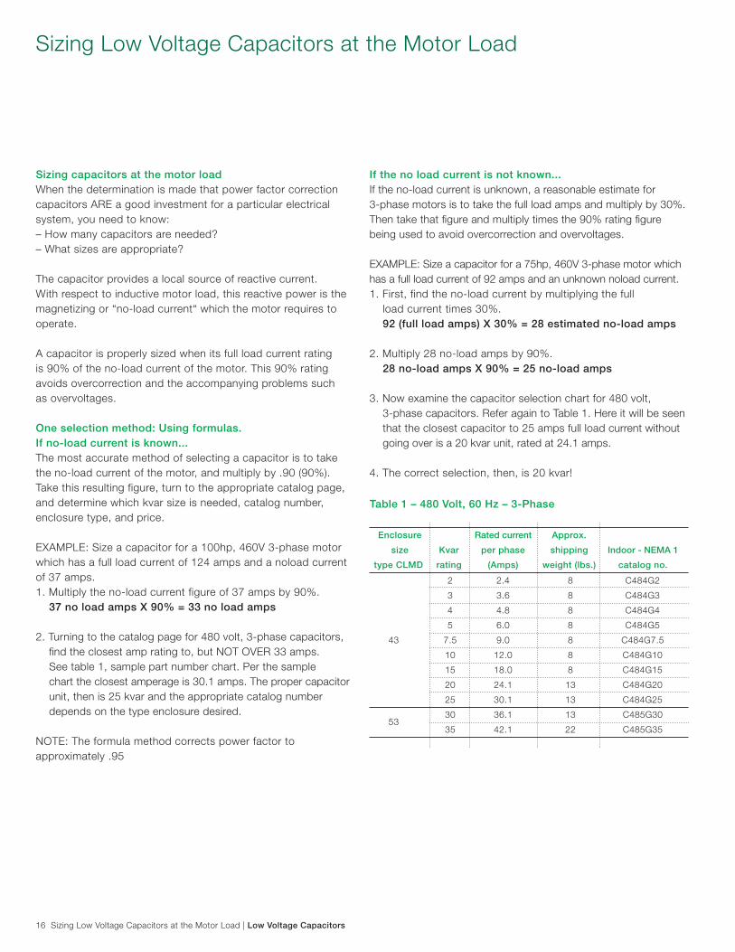
EXAMPLE: Size a capacitor for a 100hp, 460V 3-phase motor which has a full load current of 124 amps and a noload current of 37 amps.1. Multiply the no-load current figure of 37 amps by 90%. 37 no load amps X 90% = 33 no load amps
2. Turning to the catalog page for 480 volt, 3-phase capacitors, find the closest amp rating to, but NOT OVER 33 amps. See table 1, sample part number chart. Per the sample chart the closest amperage is 30.1 amps. The proper capacitor unit, then is 25 kvar and the appropriate catalog number depends on the type enclosure desired.
NOTE: The formula method corrects power factor to approximately .95
If the no load current is not known...If the no-load current is unknown, a reasonable estimate for3-phase motors is to take the full load amps and multiply by 30%. Then take that figure and multiply times the 90% rating figure being used to avoid overcorrection and overvoltages.
EXAMPLE: Size a capacitor for a 75hp, 460V 3-phase motor which has a full load current of 92 amps and an unknown noload current.1. First, find the no-load current by multiplying the full load current times 30%. 92 (full load amps) X 30% = 28 estimated no-load amps
2. Multiply 28 no-load amps by 90%. 28 no-load amps X 90% = 25 no-load amps
3. Now examine the capacitor selection chart for 480 volt, 3-phase capacitors. Refer again to Table 1. Here it will be seen that the closest capacitor to 25 amps full load current without going over is a 20 kvar unit, rated at 24.1 amps.
4. The correct selection, then, is 20 kvar!
Sizing Low Voltage Capacitors at the Motor Load
Enclosure Rated current Approx.
size Kvar per phase shipping Indoor - NEMA 1
type CLMD rating (Amps) weight (lbs.) catalog no.
2 2.4 8 C484G2
3 3.6 8 C484G3
4 4.8 8 C484G4
5 6.0 8 C484G5
43 7.5 9.0 8 C484G7.5
10 12.0 8 C484G10
15 18.0 8 C484G15
20 24.1 13 C484G20
25 30.1 13 C484G25
53
30 36.1 13 C485G30
35 42.1 22 C485G35
Table 1 – 480 Volt, 60 Hz – 3-Phase
Low Voltage Capacitors | Sizing Capacitors 17
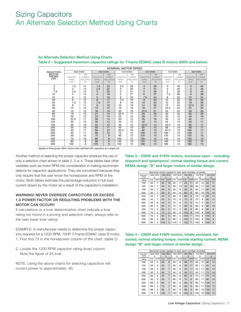
Another method of selecting the proper capacitor employs the use of only a selection chart shown in table 2, 3 or 4. These tables take other variables such as motor RPM into consideration in making recommen-dations for capacitor applications. They are convenient because they only require that the user know the horsepower and RPM of the motor. Both tables estimate the percentage reduction in full load current drawn by the motor as a result of the capacitor’s installation.
WARNING! NEVER OVERSIZE CAPACITORS OR EXCEED 1.0 POWER FACTOR OR RESULTING PROBLEMS WITH THE MOTOR CAN OCCUR!!If calculations or a kvar determination chart indicate a kvar rating not found in a pricing and selection chart, always refer to the next lower kvar rating!
EXAMPLE: A manufacturer needs to determine the proper capaci-tors required for a 1200 RPM, 75HP T-Frame EEMAC class B motor.1. First find 75 in the horsepower column of the chart. (table 2) 2. Locate the 1200 RPM capacitor rating (kvar) column. Note the figure of 25 kvar.
NOTE: Using the above charts for selecting capacitors willcorrect power to approximately .95.
Sizing Capacitors An Alternate Selection Method Using Charts
An Alternate Selection Method Using Charts Table 2 – Suggested maximum capacitor ratings for T-frame EEMAC class B motors (600V and below)
Table 3 – 2300V and 4160V motors, enclosure open – including dripproof and splashproof, normal starting torque and current, NEMA design ‘‘B’’ and larger motors of similar design.
Table 4 – 2300V and 4160V motors, totally enclosed, fan cooled, normal starting torque, normal starting current, NEMA design ‘‘B’’ and larger motors of similar design.
18 Sizing Capacitors | Low Voltage Capacitors
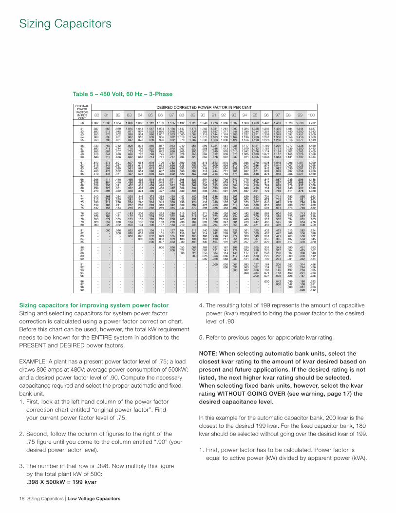
Table 5 – 480 Volt, 60 Hz – 3-Phase
Sizing Capacitors
Sizing capacitors for improving system power factorSizing and selecting capacitors for system power factorcorrection is calculated using a power factor correction chart. Before this chart can be used, however, the total kW requirement needs to be known for the ENTIRE system in addition to the PRESENT and DESIRED power factors.
EXAMPLE: A plant has a present power factor level of .75; a load draws 806 amps at 480V; average power consumption of 500kW; and a desired power factor level of .90. Compute the necessary capacitance required and select the proper automatic and fixed bank unit.1. First, look at the left hand column of the power factor correction chart entitled “original power factor”. Find your current power factor level of .75.
2. Second, follow the column of figures to the right of the .75 figure until you come to the column entitled “.90” (your desired power factor level).
3. The number in that row is .398. Now multiply this figure by the total plant kW of 500: .398 X 500kW = 199 kvar
4. The resulting total of 199 represents the amount of capacitive power (kvar) required to bring the power factor to the desired level of .90.
5. Refer to previous pages for appropriate kvar rating. NOTE: When selecting automatic bank units, select the closest kvar rating to the amount of kvar desired based on present and future applications. If the desired rating is not listed, the next higher kvar rating should be selected.When selecting fixed bank units, however, select the kvarrating WITHOUT GOING OVER (see warning, page 17) thedesired capacitance level.
In this example for the automatic capacitor bank, 200 kvar is the closest to the desired 199 kvar. For the fixed capacitor bank, 180 kvar should be selected without going over the desired kvar of 199. 1. First, power factor has to be calculated. Power factor is equal to active power (kW) divided by apparent power (kVA).
Low Voltage Capacitors | Sizing Capacitors 19
What if present power factor cannot be determined because kVA is unknown?1. First, find the apparent power (kVA). kVA demand on a 3-phase system is equal to: kVA = ( VOLTS x AMPS x √3 ) ÷ 1000
2. The voltage and amperage of the distribution system will be known. Again, using the above example, we know that the distribution system is 480 volts and draws 806 amps. Therefore: (480 VOLTS x 806 AMPS x √3 ) ÷ 1000 = 670kVA
3. Now power factor can be solved for: 500kW / 670kVA = .746 pf
4. With the power factor now known, the power factor Improvement chart can be used as before.
How is the power factor correction chart used if existing power factor level is unknown?1. First, power factor has to be calculated. Power factor is equal to active power (kW) divided by apparent power (kVA). kW will be known because it is the total amount of power consumed over a given period of time and is the amount shown on a utility bill. Therefore: pf = kW / kVA
2. Using the above example, 500kW divided by 670kVA equals a present power factor (pf) of .746. 500kW / 670kVA = .746 pf
3. When DETERMINING power factor, always round off to the next higher rating. Therefore, the .746 power factor figure is rounded off to .75. 4. Now that present power factor is known, the above problem can be solved as before.
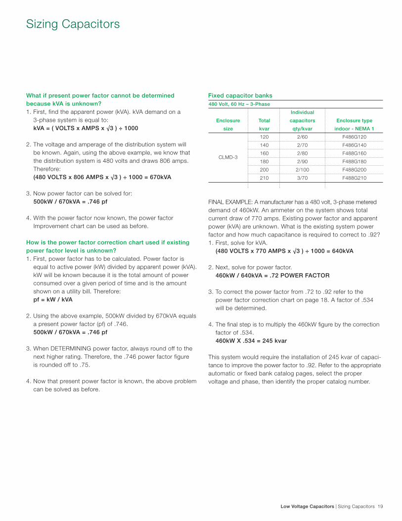
FINAL EXAMPLE: A manufacturer has a 480 volt, 3-phase metered demand of 460kW. An ammeter on the system shows total current draw of 770 amps. Existing power factor and apparent power (kVA) are unknown. What is the existing system power factor and how much capacitance is required to correct to .92?1. First, solve for kVA. (480 VOLTS x 770 AMPS x √3 ) ÷ 1000 = 640kVA
2. Next, solve for power factor. 460kW / 640kVA = .72 POWER FACTOR
3. To correct the power factor from .72 to .92 refer to the power factor correction chart on page 18. A factor of .534 will be determined.
4. The final step is to multiply the 460kW figure by the correction factor of .534. 460kW X .534 = 245 kvar
This system would require the installation of 245 kvar of capaci-tance to improve the power factor to .92. Refer to the appropriate automatic or fixed bank catalog pages, select the proper voltage and phase, then identify the proper catalog number.
Sizing Capacitors
Fixed capacitor banks 480 Volt, 60 Hz – 3-Phase
Individual
Enclosure Total capacitors Enclosure type
size kvar qty/kvar indoor - NEMA 1
120 2/60 F486G120
140 2/70 F486G140
CLMD-3
160 2/80 F488G160
180 2/90 F488G180
200 2/100 F488G200
210 3/70 F488G210
Contact Us
1SX
P98
1001
D02
02/A
pril
201
1Regional offices across Canada
Eastern region ABB Inc.2117 – 32e AvenueLachine, QC H8T 3J1Tel.: 514-420-3100Fax: 514-420-3137Toll Free: 1 800-567-0283 Central region ABB Inc.201 Westcreek Blvd.Brampton, ON L6T 5S6Tel.: 905-460-3000Fax: 905-460-3395 Western region ABB Inc.#110, 4411-6th Avenue S.E.Calgary, AB T2G 4E8Tel.: 403-278-7111Fax: 403-278-8232 ABB Inc.9418-39th Avenue NWEdmonton, AB T6E 5T9Tel.: 780 447-4677Fax: 780 455-4527
www.abb.ca
Regional offices across USA
ABB Inc.3700 West Sam Houston Parkway SouthHouston, TX 77042Toll Free: 1 888-385-1221 ABB Inc. 400 Crown Colony DriveQuincy, MA 02169Toll Free: 1 888-385-1221
www.abb.com