abaqus/multiphysics
DESCRIPTION
ABAQUS MULTIPHYSICSTRANSCRIPT
3DS.
COM/
SIMU
LIA©
Das
sault
Sys
tèmes
| ref.
: 3DS
_Doc
umen
t_201
2
Ramji KamakotiTechnical Specialist
May 13, 2013
Multiphysics in Abaqus with Emphasis on Fluid Modeling
2
Overview
• Introduction• SIMULIA Multiphysics • Abaqus/CFD• Fluid-Structure Interaction• Coupled Eulerian-Lagrangian (CEL) approach • Smoothed Particle Hydrodynamics (SPH) approach • Comparison of CFD, CEL and SPH
3DS.
COM/
SIMU
LIA©
Das
sault
Sys
tèmes
| ref.
: 3DS
_Doc
umen
t_201
2
Introduction

4
What is Multiphysics?Definition: Multiphysics is the inclusion of multiple physical representations to capture real-world phenomena • Collection of individual physical phenomena
• Full 3-D physical “field” models (structural, thermal, EMag, chemistry, …)
• Efficient abstractions of physical phenomena (1-D/logical models, substructures)
• Interaction between various physical phenomena• Sequential simulation chains (EM→thermal→structural,
submodeling, multiscale …)• Co-simulation (FSI, logical-physical, multiscale,
embedded, …)

5
Why Multiphysics?
• Crucial to include multiphysics in the design of many engineering systems• Fluid-Structure interaction - Important to include fluid-
structure interaction (FSI) in the design of aircraft wings and turbine blades
• Multiple physics representation has to be taken into account for the analysis of Aneurysms and heart valves
• Thermal-mechanical coupling - Sections of bridges and highways expand on hot days, and many plastics become extremely brittle at low temperatures
• Electrical-thermal interactions - high-density microchip circuits often create large heat loads that need to be managed with heat-transfer techniques
• Etc …• Failure to include multiphysics can lead to
catastrophic phenomenon • Tacomas Narrows Bridge – Wind-induced collapse
due to aeroelastic flutter in 1940

6
Fluid-Structure Interaction
• Fluid-Structure Interaction (FSI) represents multiphysics problems where • fluid flow affects compliant structures which in turn affect the fluid flow.
Ink droplet formation and discharge from a piezoelectric inkjet printer nozzle
Fluid
PressureVelocity
Temperature
Structure
Displacement
ElectricalTemperature
TemperatureTemperature
Fields
Fields
Electrical

7
Specialized FSI
• Contact increases solution complexity and requires specialized analysis techniques.
ElectricalElectrical
Temperature
Temperature
Temperature
Temperature
Fluid
PressureVelocity
Structure
Displacement Fields
Fields
Contact
Vacuum removal of paper trim

3DS.
COM/
SIMU
LIA©
Das
sault
Sys
tèmes
| ref.
: 3DS
_Doc
umen
t_201
2
SIMULIA Multiphysics

9
Overview of SIMULIA Multiphysics
• Multiphysics solutions offered by SIMULIA broadly falls into three different areas
• Native multiphysics capabilities available in Abaqus• Broad range of physics
Abaqus Multiphysics

10
SIMULIA Multiphysics
• Extended multiphysics capability• CEL in Abaqus/Explicit• SPH in Abaqus/Explicit• Abaqus/CFD
Extended Multiphysics
CEL SPH
CFD
• Native multiphysics capabilities available in Abaqus• Broad range of physics
Abaqus Multiphysics
• Multiphysics solutions offered by SIMULIA broadly falls into three different areas

11
SIMULIA Multiphysics
• Open scalable platform for partners and customers• Co-simulation engine• Native FSI capability• Coupling with third-party CFD codes
Multiphysics Coupling
SIMULIA Co-simulation Engine
Abaqus/Structural
Abaqus/CFD
Abaqus/EM
Other codes
• Extended multiphysics capability• CEL in Abaqus/Explicit• SPH in Abaqus/Explicit• Abaqus/CFD
Extended Multiphysics
• Native multiphysics capabilities available in Abaqus• Broad range of physics
Abaqus Multiphysics
• Multiphysics solutions offered by SIMULIA broadly falls into three different areas
Abaqus 6.12 MpCCI 4 Fluent 12
CSEAbaqus 6.12 Abaqus/CFD 6.12
Abaqus 6.12 Star-CCM+ 7.02CSE

12
Abaqus Mulitphysics
• Abaqus enables coupling of multiple fields
Courtesy: Honeywell FM&T
Courtesy of Dr. Michelle Hoo Fatt (University of Akron)
Tire noise
Bottle dropUltrasonic motor
Ball grid array
Earthen Dam
Thermal-Mechanical Structural-Acoustic
PiezoelectricFluid-Mechanical
Structural-pore fluid diffusion
Thermal-Electrical
Fuse

13
Coupled Eulerian-Lagrangian (CEL)
Courtesy: JP Kenny
Eulerian material definitions can interact with Lagrangian elements through contact in Abaqus/ExplicitMulti-material finite element formulation (Volume-of-Fluids method) tracks material boundary in EuleriandomainInterface interactions created using general contact definitionsAutomatic refinement of Eulerian elements improves accuracy and performance

14
Particle Methods: SPH
Mesh-free Lagrangian particlesAutomatic conversion from conventional elements to SPH particlesApplications include ballistic impact with fragmentation, class of fluid problems
Courtesy of US Dept of Health

15
• 88% efficiency for fixed-work per processor at 64 cores
• Mesh sizes limited only by pre and post capabilities
Abaqus/CFD – General purpose flow solver
Coupling with Abaqus/Standard and Abaqus/Explicit
2nd-order accurate in space and time
Turbulence modelingSpalart-Allmarask-epsilonILES
Incompressible pressure-based
flow solverTransient ,
Laminar and Turbulent flows, Heat transfer and
Natural convection
Superior and robust hybrid
FV/FEM discretization
Robust and fast iterative solvers, AMG, GMRES,
etc.
Fully parallel and scalable
Arbitrary Lagrangian-
Eulerian (ALE)
Native FSI capability
Abaqus/CAE pre and post support
16
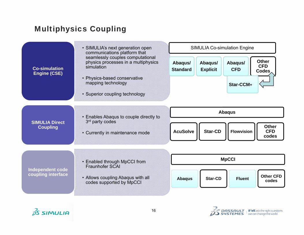
Multiphysics Coupling
• SIMULIA’s next generation open communications platform that seamlessly couples computational physics processes in a multiphysics simulation
• Physics-based conservative mapping technology
• Superior coupling technology
Co-simulation Engine (CSE)
• Enables Abaqus to couple directly to 3rd party codes
• Currently in maintenance mode
SIMULIA Direct Coupling
• Enabled through MpCCI from Fraunhofer SCAI
• Allows coupling Abaqus with all codes supported by MpCCI
Independent code coupling interface
Abaqus
AcuSolve Star-CD FlowvisionOther CFD
codes
MpCCI
Abaqus Star-CD Fluent Other CFD codes
SIMULIA Co-simulation Engine
Abaqus/Standard
Abaqus/Explicit
Abaqus/CFD
Other CFD
Codes
Star-CCM+Star-CCM+

17
SIMULIA FSI Solutions
• Several methods available to address diverse industry needs
SIMULIA FSI Solutions
Con
tact
com
plex
ity a
t int
erfa
ce
Linear structures
SWAGELOK pressure regulator
Specialized techniques
Coupled Eulerian-
Lagrangian (CEL)
Smoothed Particle
Hydrodynamics (SPH)
Multiphysics Coupling
Partitioned approach
Structural solver
Fluid solver
Solenoid Valve

3DS.
COM/
SIMU
LIA©
Das
sault
Sys
tèmes
| ref.
: 3DS
_Doc
umen
t_201
2
Abaqus/CFD

19
Abaqus/CFD
• Abaqus/CFD is the computational fluid dynamics (CFD) analysis capability offered in the Abaqus product suite to perform flow analysis
• Scalable CFD solution in an integrated FEA-CFD multiphysics framework
• Based on hybrid finite-volume and finite-element method
• Incompressible, pressure-based flow solver:
• Laminar & turbulent flows
Pressure contours
Aortic Aneurysm
Pressure contours on submarine skin
Submarine

20
Abaqus/CFD
• Incompressible, pressure-based flow solver:• Transient (time-accurate) method
• 2nd-order accurate projection method
• Steady-state using pseudo-time marching and backward-Euler method
• 2nd-order accurate least squares gradient estimation
• Implicit and explicit advection schemes
• Unsteady RANS approach (URANS) for turbulent flows
• Energy equation for thermal analysis
• Buoyancy driven flows (natural convection)
• Uses the Boussinesq approximation
• Isotropic porous media flow modeling • Includes isothermal and non-isothermal
flow modeling
Flow Around Obstacles(Vortex Shedding)
Electronics Cooling(Buoyancy driven flow due to
heated chips)
Velocity contours
Velocity vectors
Inlet
Outlet
Substrate
Pressure
porous media flow
21
Abaqus/CFD
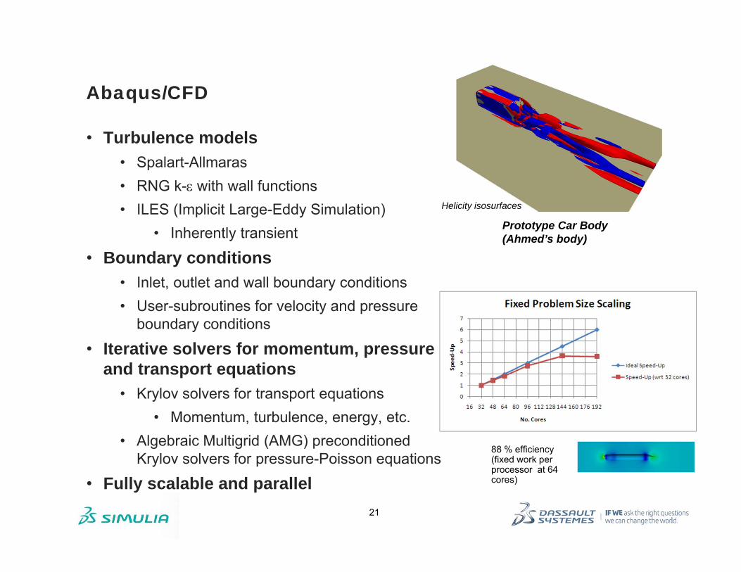
• Turbulence models• Spalart-Allmaras• RNG k-with wall functions• ILES (Implicit Large-Eddy Simulation)
• Inherently transient
• Boundary conditions• Inlet, outlet and wall boundary conditions• User-subroutines for velocity and pressure
boundary conditions
• Iterative solvers for momentum, pressure and transport equations
• Krylov solvers for transport equations• Momentum, turbulence, energy, etc.
• Algebraic Multigrid (AMG) preconditioned Krylov solvers for pressure-Poisson equations
• Fully scalable and parallel
88 % efficiency (fixed work per processor at 64 cores)
Helicity isosurfaces
Prototype Car Body(Ahmed’s body)
22
Abaqus/CFD
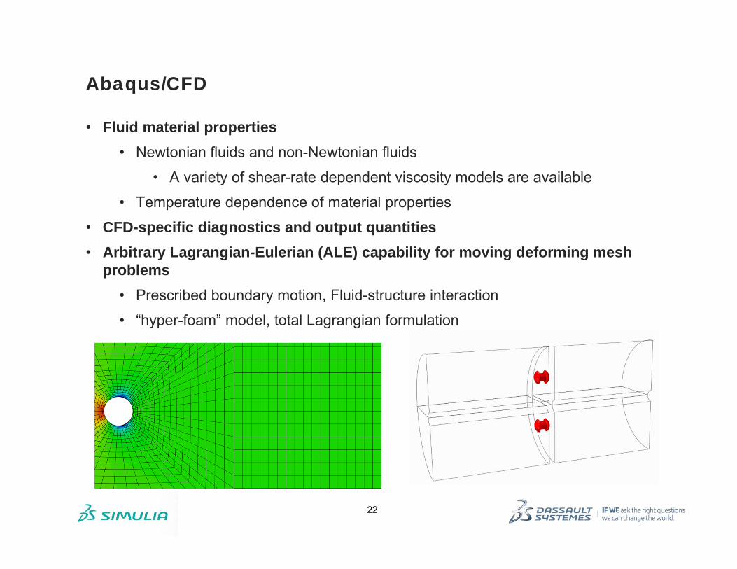
• Fluid material properties• Newtonian fluids and non-Newtonian fluids
• A variety of shear-rate dependent viscosity models are available
• Temperature dependence of material properties
• CFD-specific diagnostics and output quantities• Arbitrary Lagrangian-Eulerian (ALE) capability for moving deforming mesh
problems• Prescribed boundary motion, Fluid-structure interaction
• “hyper-foam” model, total Lagrangian formulation

23
Abaqus/CFD
• Abaqus/CAE support• Concept of “model type” in Abaqus/CAE
• Model type “CFD” enables CFD model creation
• Support for CFD-specific attributes
• Step definition
• Initial conditions
• Boundary conditions and loads
• Job submission, monitoring etc.

24
Abaqus/CFD
• Abaqus/Viewer support for Abaqus/CFD• CFD output database
• Isosurfaces
• Multiple cut-planes
• Vector plots
• Instantaneous particle traces
Temperature contours
Temperature isosurfaces
Velocity vectors on intermediate plane
Pressure contours
Velocity vectors
Temperature contours

3DS.
COM/
SIMU
LIA©
Das
sault
Sys
tèmes
| ref.
: 3DS
_Doc
umen
t_201
2
Fluid-Structure Interaction
26
What is Fluid-Structure Interaction or FSI?
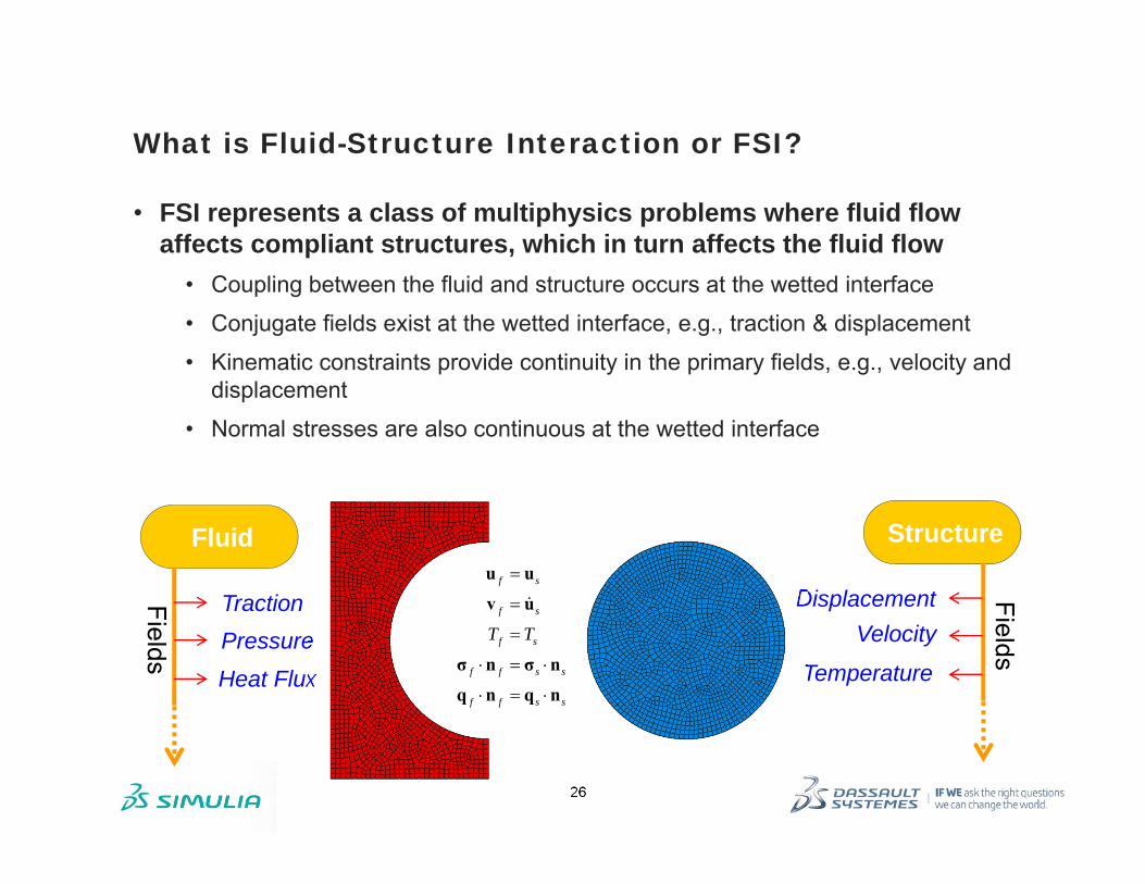
• FSI represents a class of multiphysics problems where fluid flow affects compliant structures, which in turn affects the fluid flow
• Coupling between the fluid and structure occurs at the wetted interface
• Conjugate fields exist at the wetted interface, e.g., traction & displacement
• Kinematic constraints provide continuity in the primary fields, e.g., velocity and displacement
• Normal stresses are also continuous at the wetted interface
Heat Flux
Fluid
TractionPressure
Fields
Structure
Displacement Fields
Temperature
Velocity
f s
f s
f s
f f s s
f f s s
T T
u u
v u
σ n σ n
q n q n

27
Survey of FSI Technology
• Linear Structures Approach• Linear solid/structural deformation• Eigenmodes sufficient to represent the
dynamic behavior • Projection of dynamic system onto the
eigenspace• Segregated Approach
• Structural and fluid equations solved independently
• Interface loads and boundary conditions exchanged after a converged increment
• Stabilizing terms required• Monolithic Approach
• Fully-coupled system of Equations• Can be difficult to solve• Can avoid stability issues
• Specialized Techniques• Coupled Eulerian-Lagrangian
Ma Cv Kd F
my +cy +ky = f modes( ) 0 1,...,i i i n K M S
Structural Solver Fluid Solver
( )f f f f f f f f f f
Tf f f f
T
f x y z
p t
K p
v v v
MV A V V KV C F
CV
V
s s s s s s s
s x y z
K t
u u u
MU CU U F
U
Τ
Abaqus native FSI capability is based on a stabilized segregated approach

28
Native FSI Using Abaqus
Coupling Abaqus/Standard + Abaqus/CFD
Abaqus/Explicit + Abaqus/CFD
Fluid structure interaction (FSI)
Conjugate heat-transfer (CHT)
Fluid-structure interactionButterfly valve
Conjugate heat transferHeat exchanger

29
Native FSI Using Abaqus
• Abaqus/CFD can be ccoupled with both Abaqus/Standard and Abaqus/Explicit through the co-simulation engine
• The co-simulation engine operates in the background (no user intervention required)
• Physics-based conservative mapping on the FSI interface
• Significantly expands the set of FSI applications that SIMULIA can address
• Fluid-structure interaction
• Also supports conjugate heat-transfer applications
Abaqus/Standard
Co-Simulation
Abaqus/Explicit
Abaqus/CFD

30
Native FSI Using Abaqus
• Rigorous decomposition of the fully-coupled system
• Retain segregated solution approach
• Interfacial inertial effects
• Stabilization provides temporal convergence in a one-step algorithm
• Time increment may be selected to resolve the physical time-scales

31
Native FSI Using Abaqus
• Supported though Abaqus/CAE
• Support for creating “FSI” interactions in
• Structural analysis (in Abaqus/Standard or Abaqus/Explicit)
• CFD analysis (in Abaqus/CFD)
• FSI jobs launched through co-execution framework

3DS.
COM/
SIMU
LIA©
Das
sault
Sys
tèmes
| ref.
: 3DS
_Doc
umen
t_201
2
Coupled Eulerian-Lagrangian (CEL) Approach

33
Coupled Eulerian-Lagrangian (CEL) Approach
• Three relationships between the mesh and underlying material are provided in Abaqus/Explicit:
• Lagrangian• Arbitrary Lagrangian-Eulerian (ALE)
adaptive meshing• Eulerian
• Lagrangian description: Nodes are fixed within the material
• It is easy to track free surfaces and to apply boundary conditions.
• The mesh will become distorted with high strain gradients.
1
Lagrangian formulation
Impact of a copper rod

34
Coupled Eulerian-Lagrangian (CEL) Approach
• Arbitrary Lagrangian-Eulerian (ALE) adaptive meshing: mesh motion is constrained to the material motion only at free boundaries • It is easy to track free surfaces.• Mesh distortion is minimized by adjusting mesh
within the material free boundaries.
Lagrangian formulationALE formulation
ALE formulation
2

35
Coupled Eulerian-Lagrangian (CEL) Approach
• Eulerian description: nodes stay fixed while material flows through the mesh.
• It is more difficult to track free surfaces.
• No mesh distortion because the mesh is fixed.
Eulerian formulation
ALE formulation
Lagrangian formulation
Eulerian formulation
Eulerian mesh
rod material
Mesh refinement needed in impact zone to more accurately capture strain gradient
3

36
Coupled Eulerian-Lagrangian (CEL) Approach
• Coupled Eulerian-Lagrangian (CEL) approach:• An Eulerian mesh and a Lagrangian mesh are assembled in the same
model.
• Interactions between Lagrangian bodies and materials in the Eulerian mesh are enforced with a general contact definition.
Front-load washing machine
Tub (Lagrangian)
Round object (Lagrangian)
Water (Eulerian)

37
CEL Analysis Technique
• Technical Approach• The Eulerian-Lagrangian capability uses a multi-material finite element
formulation
• Volume-of-Fluids (VOF) method tracks material boundary in the Eulerian domain
• Interface interactions created using general contact definitions
• Conforming meshes not required
• Specialized technique to handle certain types of Fluid-Structure Interaction (FSI) problems:
• Extreme contact including self-contact
• Large scale structural deformations and displacements
• High-speed dynamic events
• Damage, failure, or erosion of the interface

3DS.
COM/
SIMU
LIA©
Das
sault
Sys
tèmes
| ref.
: 3DS
_Doc
umen
t_201
2
Smoothed Particle Hydrodynamics (SPH) Approach

39
Smoothed Particle Hydrodynamics (SPH) Approach
• Smoothed Particle Hydrodynamics is a very general approach to the simulation of bulk matter in motion.
• SPH addresses modeling needs in cases where traditional methods (FEM, FDM) fail or are inefficient:
• Extremely violent fluid flows where mesh or grid-based CFD cannot cope (free surface)
• Extremely high deformations/obliteration where CEL is inefficient and Lagrangian FEM is difficult
Liquid spraying through a hoseWater fall under gravity

40
Smoothed Particle Hydrodynamics (SPH) Approach
• The earliest applications of SPH were mainly focused on fluid dynamics.
• Then its use was extended to the simulation of:
• The fracture of brittle solids
• Metal forming
• High (or hyper) velocity impact (HVI)
• Explosion phenomena caused by the detonation of high explosives
Priming a PumpProjectile impact
continuum solid projectile
SPH patch

41
Smoothed Particle Hydrodynamics (SPH) Approach
• The novelty of SPH lies in a specific method for smooth interpolation and differentiation within an irregular grid of moving macroscopic particles.
• Because nodal connectivity is not fixed, severe element distortion is avoided; hence, the formulation allows for very high strain gradients.
• The conservation of mass, linear momentum, and energy are satisfied exactly.
Kernel function W(r)Particle
Neighbors

42
Smoothed Particle Hydrodynamics (SPH) Approach
• SPH in Abaqus• SPH analysis is an Abaqus/Explicit capability implemented for three-
dimensional models.
• Any of the material models available in Abaqus/Explicit, including user-defined materials, can be used.
• Initial and boundary conditions can be specified as for any Lagrangian model.
• Concentrated nodal loads can be applied in the usual way.
Spray can nozzle

3DS.
COM/
SIMU
LIA©
Das
sault
Sys
tèmes
| ref.
: 3DS
_Doc
umen
t_201
2
Comparison of CFD, CEL, and SPH

44
Material Considerations
• Material types• SPH can use any material available in Abaqus/Explicit,
• CEL can use any isotropic material available in Abaqus/Explicit
• CFD can simulate only incompressible fluids
CEL SPH CFD
TypeSolids
isotropic
anisotropic
Fluids
Compressibility
Compressible
Nearly incompressible
Incompressible

45
Material Considerations
• Multiple materials• CEL can simulate multiple materials interacting
Projectile impacting solid plate (SPH)
continuum solid projectile
SPH patch
sand
water
air
Multiple materials interacting (CEL)
CEL SPH CFD
Single material
Multiple materials interacting
Interactions via contact or FSI co-simulation
46
Material Considerations
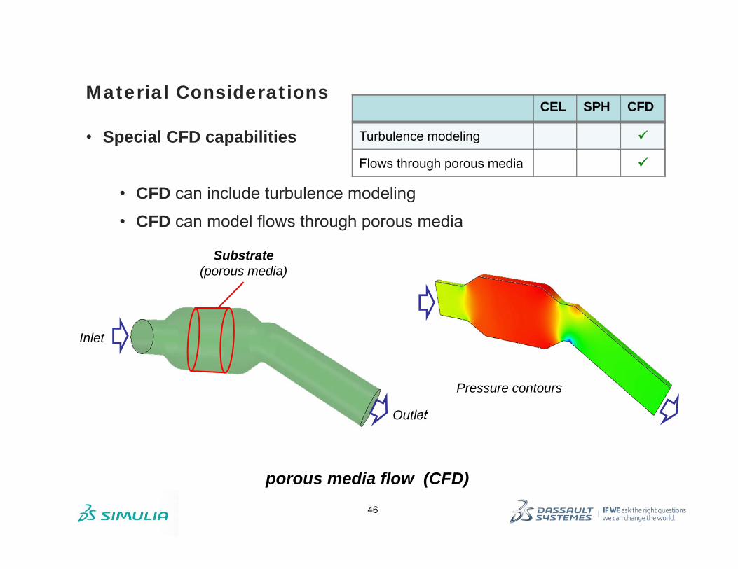
• Special CFD capabilities
• CFD can include turbulence modeling
• CFD can model flows through porous media
Inlet
Outlet
Substrate (porous media)
Pressure contours
porous media flow (CFD)
CEL SPH CFD
Turbulence modeling
Flows through porous media

47
• Material motion• CFD and CEL both allow for material flow through the mesh
Material Considerations
CELtire Hydroplaning
fluid outflow
fluid inflow
CFD Vortex Shedding behind a cylinder
fluid inflow
fluid outflow
CEL SPH CFD
Material inflow and outflow

48
Material Considerations
SPH Two-Lobe Cavity Pump: Water pushed while pump is rotating
• Material motion• CFD and CEL both allow for material flow through the mesh
• SPH uses a strictly Lagrangian formulation
• Inflow and outflow conditions can only be modeled via more expensive inflow and outflow volumetric regions
CEL SPH CFD
Material inflow and outflow

49
• Inflators• Inflators can be used to introduce gas in CEL simulations
• Limited inflators can be modeled in SPH via long columns with fluid pushed down via a plate
Initial geometry
Early deployment
Deployment complete
Material Considerations
CEL Side curtain airbag deployment Inflator injects gas into the air bag throughout the simulation
Courtesy of TAKATA SPH inflation
Long column of fluid pushed in
CEL SPH CFD
Inflators

50
Contact Considerations
• Contact interface: conforming meshes• CEL allows you to create a simple mesh which does not conform to the
surrounding structure
• CFD FSI requires a conforming mesh
• SPH particles cannot overlap with other surrounding Lagrangian bodies
CEL structure moves through
Eulerian mesh
CFD FSI CFD mesh conforms to structure
SPHparticles inside structure
CEL SPH CFD
Mesh need not conform to surrounding structure

51
Contact Considerations
• Contact interface: topology changes• CEL and SPH can be used to perform FSI analyses with penetration
and/or pinching
• CFD FSI fluid boundaries can move or deform, but not change topologically
CEL projectile impact and penetration
SPH Grease filled CV joint
CEL SPH CFD
Contact interface topology can change

52
Contact Considerations
• Contact with immersed shell structures• With SPH and CFD FSI flow is discontinuous on either side of an
immersed shell structure because the boundaries are Lagrangian
• CEL smears the discontinuity over the element that the shell intersects
Discontinuous streamlines and pressure contours in flow over a
flexible flap in a converging channel (CFD/STD co-simulation)
Notes: • The same comparison is true for the
temperature field in heat transfer simulations (CFD FSI and CEL only)
• Abaqus/CAE includes a “seam” feature to support CFD in this regard.
1. Partition cell
2. Assign seam
CEL SPH CFD
Solution discontinuities on either side of an immersed shell

53
Geometry and Mesh
SPH liquid can pass through a narrow channel
initial
final
• Capturing flow near small geometric details
• SPH does not require high mesh refinement around obstacles with small geometric details, nor within narrow passages
• CEL and CFD require a minimum of several elements across a passage to represent flow
• However, CEL can automatically refine and coarsen the mesh locally during the simulation to better capture small details and local behavior
Indentation (CEL) with automatic mesh refinement
CEL SPH CFD
Does not require high mesh refinement around obstacles with small geometric details

54
Geometry and Mesh
• Element conversion• SPH allows for conversion of continuum finite elements into SPH
particles• You define a finite element mesh using brick, wedge and
tetrahedron elements that can convert to SPH particles • Conversion can happen either at beginning of the analysis or
during the analysis based on some criterion• With CFD and CEL the nature of the mesh does not change during
the analysis
Continuum elements progressively converted to SPH particles as the specified maximum principal strain is reached in each element representing the bird
Bird
Engine blade
CEL SPH CFD
Element conversion

55
Geometry and Mesh
CEL fluid surface rendered
CFD cannot represent a fluid
material free surface
SPH fluid particles rendered
• Free surface visualization
• Choose CEL over CFD, and SPH when you need clear visualization of the fluid material free surface
CEL SPH CFD
Clearest definition of material free surface NA
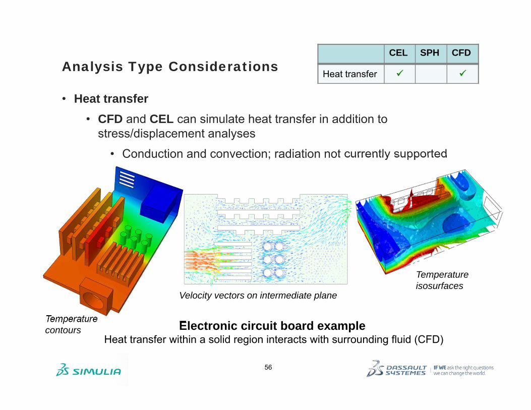
56
• Heat transfer• CFD and CEL can simulate heat transfer in addition to
stress/displacement analyses
• Conduction and convection; radiation not currently supported
Analysis Type Considerations
Electronic circuit board exampleHeat transfer within a solid region interacts with surrounding fluid (CFD)
Temperature contours
Temperature isosurfaces
Velocity vectors on intermediate plane
CEL SPH CFD
Heat transfer

57
Computational Considerations
• Accuracy• CEL and CFD deliver approximately the same level of accuracy for the
same level of mesh refinement
• When applied to deformation regimes amenable to the Lagrangian finite element and CEL methods, SPH may produce less accurate results
• SPH technique is effective in applications involving extreme deformations and fragmentation
Relative accuracy(generally speaking) CFD ≈ CEL≥ SPH

58
Computational Considerations
• Performance and computational cost
• CFD can use large time increments to run long-duration transient simulations
• CEL and SPH are limited to explicit time integration and relatively small time increments
• For a given computer resource (memory and CPU) CFD can have a much finer mesh than CEL
• The high computational cost of CEL simulations for problems with a small material-to-void ratio may require the use of SPH
• For example, tracking fragments from primary impact through a large volume until secondary impact occurs
CEL SPH CFD
Large time increments
Much finer mesh for a given computer resource NA
Better performance with small material-to-void ratio
NA

3DS.
COM/
SIMU
LIA©
Das
sault
Sys
tèmes
| ref.
: 3DS
_Doc
umen
t_201
2