abaqus keywords in ansa
DESCRIPTION
Abaqus, ansaTRANSCRIPT

How to define ABAQUS keywords in ANSA ANSA v13.x
BETA CAE Systems S.A.
How to define ABAQUS keywords in ANSA ANSA v14.x.x
GENERAL REMARKS
1. How to determine parameters of keywords specified with names.
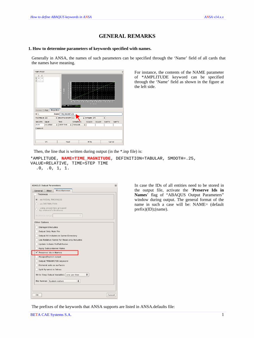
Generally in ANSA, the names of such parameters can be specified through the ‘Name’ field of all cards that the names have meaning.
For instance, the contents of the NAME parameter of *AMPLITUDE keyword can be specified through the ‘Name’ field as shown in the figure at the left side.
Then, the line that is written during output (in the *.inp file) is:
*AMPLITUDE, NAME=TIME_MAGNITUDE, DEFINITION=TABULAR, SMOOTH=.25, VALUE=RELATIVE, TIME=STEP TIME
.0, .0, 1, 1.
In case the IDs of all entities need to be stored in the output file, activate the ‘Preserve Ids in Names’ flag of “ABAQUS Output Parameters” window during output. The general format of the name in such a case will be: NAME= (default prefix)(ID);(name).
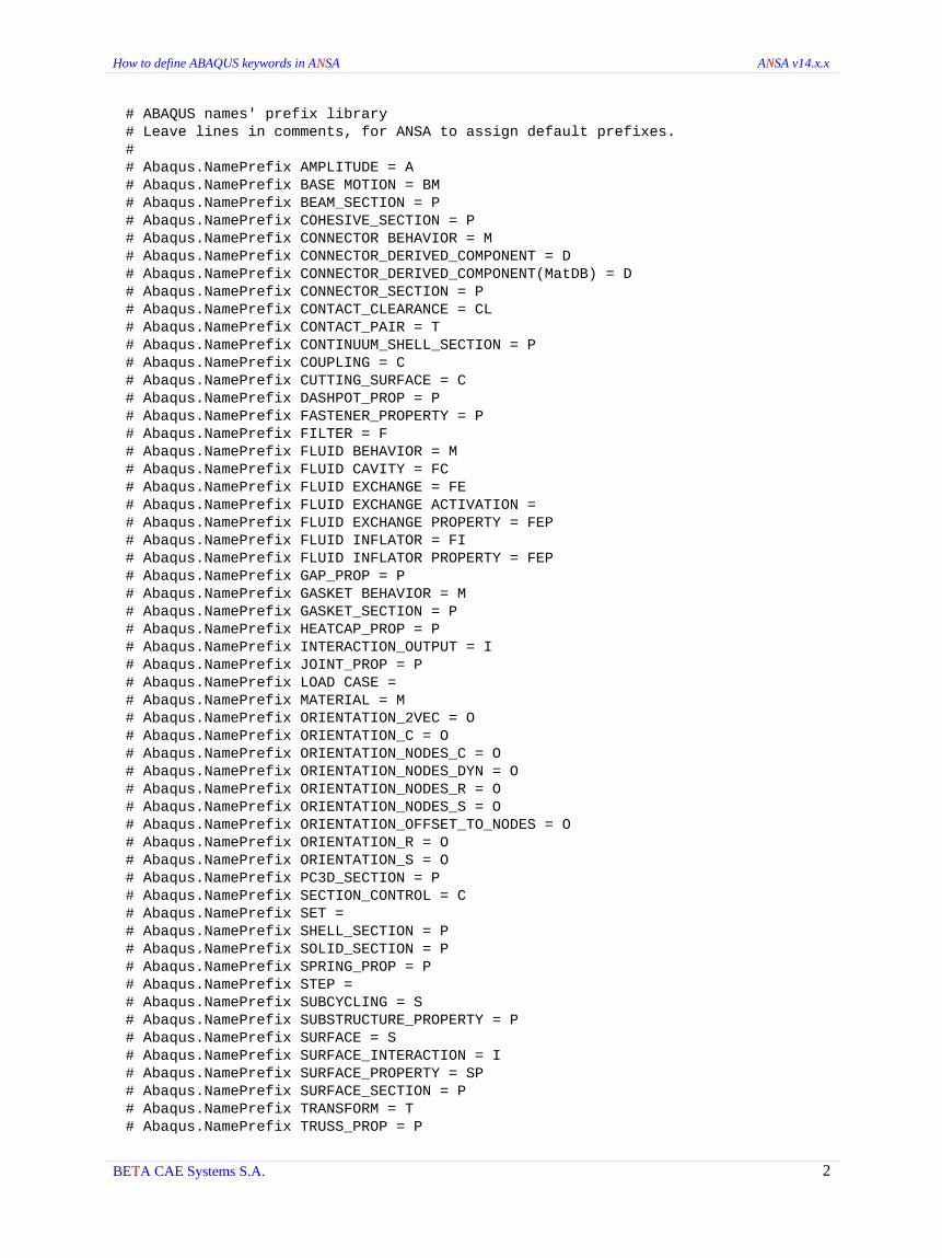
The prefixes of the keywords that ANSA supports are listed in ANSA.defaults file:
BETA CAE Systems S.A. 1
How to define ABAQUS keywords in ANSA ANSA v14.x.x
# ABAQUS names' prefix library # Leave lines in comments, for ANSA to assign default prefixes. # # Abaqus.NamePrefix AMPLITUDE = A # Abaqus.NamePrefix BASE MOTION = BM # Abaqus.NamePrefix BEAM_SECTION = P # Abaqus.NamePrefix COHESIVE_SECTION = P # Abaqus.NamePrefix CONNECTOR BEHAVIOR = M # Abaqus.NamePrefix CONNECTOR_DERIVED_COMPONENT = D # Abaqus.NamePrefix CONNECTOR_DERIVED_COMPONENT(MatDB) = D # Abaqus.NamePrefix CONNECTOR_SECTION = P # Abaqus.NamePrefix CONTACT_CLEARANCE = CL # Abaqus.NamePrefix CONTACT_PAIR = T # Abaqus.NamePrefix CONTINUUM_SHELL_SECTION = P # Abaqus.NamePrefix COUPLING = C # Abaqus.NamePrefix CUTTING_SURFACE = C # Abaqus.NamePrefix DASHPOT_PROP = P # Abaqus.NamePrefix FASTENER_PROPERTY = P # Abaqus.NamePrefix FILTER = F # Abaqus.NamePrefix FLUID BEHAVIOR = M # Abaqus.NamePrefix FLUID CAVITY = FC # Abaqus.NamePrefix FLUID EXCHANGE = FE # Abaqus.NamePrefix FLUID EXCHANGE ACTIVATION = # Abaqus.NamePrefix FLUID EXCHANGE PROPERTY = FEP # Abaqus.NamePrefix FLUID INFLATOR = FI # Abaqus.NamePrefix FLUID INFLATOR PROPERTY = FEP # Abaqus.NamePrefix GAP_PROP = P # Abaqus.NamePrefix GASKET BEHAVIOR = M # Abaqus.NamePrefix GASKET_SECTION = P # Abaqus.NamePrefix HEATCAP_PROP = P # Abaqus.NamePrefix INTERACTION_OUTPUT = I # Abaqus.NamePrefix JOINT_PROP = P # Abaqus.NamePrefix LOAD CASE = # Abaqus.NamePrefix MATERIAL = M # Abaqus.NamePrefix ORIENTATION_2VEC = O # Abaqus.NamePrefix ORIENTATION_C = O # Abaqus.NamePrefix ORIENTATION_NODES_C = O # Abaqus.NamePrefix ORIENTATION_NODES_DYN = O # Abaqus.NamePrefix ORIENTATION_NODES_R = O # Abaqus.NamePrefix ORIENTATION_NODES_S = O # Abaqus.NamePrefix ORIENTATION_OFFSET_TO_NODES = O # Abaqus.NamePrefix ORIENTATION_R = O # Abaqus.NamePrefix ORIENTATION_S = O # Abaqus.NamePrefix PC3D_SECTION = P # Abaqus.NamePrefix SECTION_CONTROL = C # Abaqus.NamePrefix SET = # Abaqus.NamePrefix SHELL_SECTION = P # Abaqus.NamePrefix SOLID_SECTION = P # Abaqus.NamePrefix SPRING_PROP = P # Abaqus.NamePrefix STEP = # Abaqus.NamePrefix SUBCYCLING = S # Abaqus.NamePrefix SUBSTRUCTURE_PROPERTY = P # Abaqus.NamePrefix SURFACE = S # Abaqus.NamePrefix SURFACE_INTERACTION = I # Abaqus.NamePrefix SURFACE_PROPERTY = SP # Abaqus.NamePrefix SURFACE_SECTION = P # Abaqus.NamePrefix TRANSFORM = T # Abaqus.NamePrefix TRUSS_PROP = P
BETA CAE Systems S.A. 2
How to define ABAQUS keywords in ANSA ANSA v14.x.x
Thus for the above example, the NAME of *AMPLITUDE will have the following format during output:
*AMPLITUDE, NAME=A1;TIME_MAGNITUDE, DEFINITION=TABULAR, SMOOTH=.25, VALUE=RELATIVE, TIME=STEP TIME.0, .0, 1., 1.
The user is able to give own prefixes by un-commenting the desired Abaqus.NamePrefixes (remove the # symbol at the start of the line) and typing the name after the equal symbol of each Abaqus.NamePrefix (up to four characters can be specified). For example:
# ABAQUS names' prefix library# Leave lines in comments, for ANSA to assign default prefixes.Abaqus.NamePrefix AMPLITUDE = TIMG.
In this case, the name of NAME parameter will have the following format during output (have in mind that ‘Preserve Ids in Names’ flag of “ABAQUS Output Parameters” window should be active):
*AMPLITUDE, NAME=TIMG1;TIME_MAGNITUDE, DEFINITION=TABULAR, SMOOTH=.25, VALUE=RELATIVE, TIME=STEP TIME.0, .0, 1., 1.
In case the assignment of prefixes is unwanted for some entities, un-comment corresponding variables and leave them blank.For example:
# ABAQUS names' prefix library# Leave lines in comments, for ANSA to assign default prefixes.Abaqus.NamePrefix AMPLITUDE = Abaqus.NamePrefix BEAM_SECTION =
In this case the result during output would be:
*AMPLITUDE, NAME=(just the name specified in the card)*BEAM SECTION, ELSET=(just the name specified in the beam section card).
NOTES:
ANSA should be reopened so as to read any changes in ANSA.defaults file.
Prefixes can be defined in more than one ANSA.defaults file ( ANSA_HOME, HOME or Current directory). In order to avoid overwriting prefixes the user can un-comment the “Abaqus.NamePrefix Lock_current_state = true” line (just after the prefixes definitions). This way ANSA will not alter already read prefixes in case other prefixes will be read from other ANSA.defaults file(s).
The status of 'Preserve Ids in Names' flag of ABAQUS Output Parameters window (File>Output>ABAQUS) can be controlled by the folllowing line of ANSA.defaults file:
Abaqus.Preserve IDs in Names = YES
BETA CAE Systems S.A. 3

How to define ABAQUS keywords in ANSA ANSA v14.x.x
2. Defining non-linear material properties (as a function of temperature) in tabular forms.
The non-linear material properties can be defined in almost the same way for all material properties inside ANSA. The steps that should be followed are:
2.1 Set ‘DEP_DENS' pull down menu of the material property to YES. For example, next to the keyword *DENSITY set the option DEP_DENS to YES as shown in the figure on the right.
2.2 Press the ‘?’ key in ‘DATA TABLE DENS’ field that appears.
Name2.3 Create a new table by pressing the corresponding
button (New>DATA TABLE) in the “DATA TABLE HELP” card that opens.
2.4 Specify the values in i-columns and j-rows (as many as needed) and press OK to declare the definition. For the DEP_DENS option two columns are needed. The values in the first column are considered as density values and in the second column temperature values.
BETA CAE Systems S.A. 4
1 2
4
?
3

How to define ABAQUS keywords in ANSA ANSA v14.x.x
2.5 Double click on the entry (highlighted on the right) to set it's ID in ‘DATA TABLE DENS’ field of the MATERIAL card as shown below.
NOTES:
Each row implies one data line during output.
The values of each property are specified in each column. Temperature values are always specified in the last column of the table.
3. Fix operations for pyramid elements created inside ANSA.
The volume meshing can be implemented by using any function (mainly any algorithm of MESHV) located in VOLUMEs group of MESH menu. In many cases, when quads exist in the surface mesh of the volume, pyramid elements are automatically generated during volume meshing. The created pyramids can be fixed either by using CHECK>PYARAMIDS function (ABAQUS deck) or by activating the ‘Split Pyramid in Tetras’ flag during output (“ABAQUS Output Parameters” window).
BETA CAE Systems S.A. 5
How to define ABAQUS keywords in ANSA ANSA v14.x.x
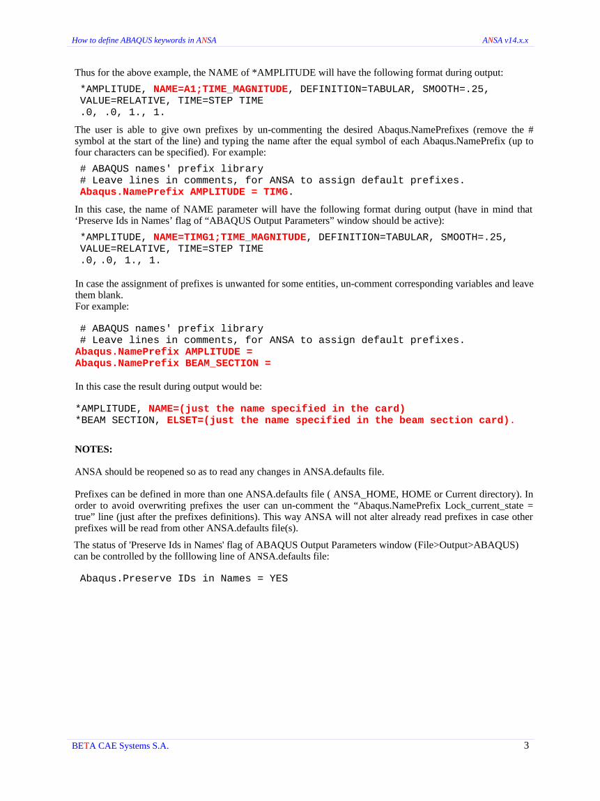
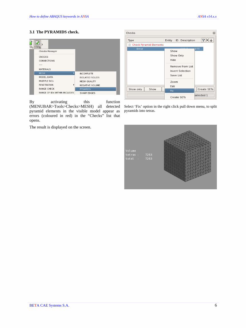
3.1 The PYRAMIDS check.
By activating this function (MENUBAR>Tools>Checks>MESH) all detected pyramid elements in the visible model appear as errors (coloured in red) in the “Checks” list that opens.
Select ‘Fix’ option in the right click pull down menu, to split pyramids into tetras.
The result is displayed on the screen.
BETA CAE Systems S.A. 6

How to define ABAQUS keywords in ANSA ANSA v14.x.x
3.2 The ‘Split Pyramid in Tetras’ flag.
By activating this flag the pyramids, which are identified according to the mode of the Output (All/Model/Visible) are automatically split into tetras during output.
A respective warning message is also reported in the Ansa Info window stating whether pyramids were detected in the model during output.
The result is presented in the current input file (*.inp).
4. Usage of ANSA tooltips, function finder for any ABAQUS keyword and subsequent parameters identification and definition of keywords through Database browser.
4.1 Tooltips
The tooltips provide valuable information on the usage of the fields and menus inside a card. When holding the mouse cursor over a field or menu, a tooltip with detailed information appears. The information is written in the same manner as in ABAQUS keywords reference manual. For instance the card in the figure on the right shows all parameters concerning the *BOUNDARY keyword and the tooltip that appears when holding the mouse cursor over the OP menu.
BETA CAE Systems S.A. 7

How to define ABAQUS keywords in ANSA ANSA v14.x.x
4.2 Search Engine
The ANSA Search Engine has similar functionality to web search engines. It provides easy search and access to ANSA functions and model data. For each of the following supported keywords, the search engine returns all possible ways the user can follow to create it. The search engine can be very useful to users that are unfamiliar with the ANSA interface, as it can be used to directly activate a function. All available functions related to the text in the search field are listed as the user types. The highlighted function can be run directly simply by pressing the enter key. The rest of the functions can be accessed either by a single mouse click or by using the up and down arrows and enter.
4.3 New keywords through Database browser
To create a new keyword right click the empty space of Database window and use New > any listed category as shown.
BETA CAE Systems S.A. 8

How to define ABAQUS keywords in ANSA ANSA v14.x.x
5. Orientation of Surfaces
All “orientable” elements (e.g. Shell, Gasket, Continuum Shell, etc) and the respective Properties contained in SETs, can be given a particular Orientation (SPOS / SNEG). This is a characteristic of the Set and can be assigned per contained entity, i.e a Shell property defined as Oriented= SPOS in one Set can be Oriented=SNEG in a different Set. Also two Properties in a Set can have different Orientation.
The orientation of the exported surface, based on the Set (Output as surface), is specified either by the “ORIENTATION” type or by the Entity's Orientation that is now available.
In order to define the orientation on a set's contained entity:
- Open the SET management window and click on Set's contents for which Orientation needs to be specified.
- The Database Browser List with these entities (e.g. Properties) appears with the Column “Oriented”. This appears as an option within the Entity's card as well. However, the field/column becomes available only through the Set management.
- Using Quick Modify you can change the field directly in the list.
BETA CAE Systems S.A. 9
How to define ABAQUS keywords in ANSA ANSA v14.x.x
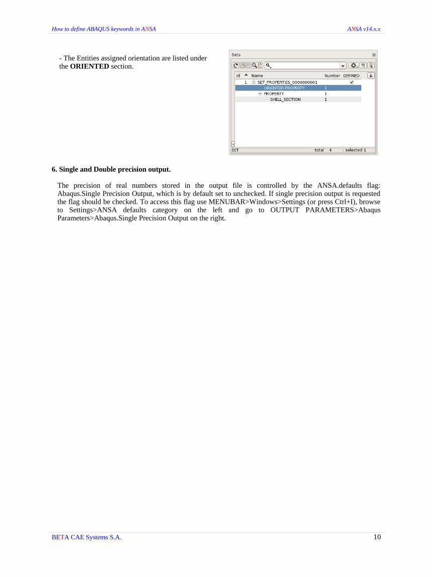
- The Entities assigned orientation are listed under the ORIENTED section.
6. Single and Double precision output.
The precision of real numbers stored in the output file is controlled by the ANSA.defaults flag: Abaqus.Single Precision Output, which is by default set to unchecked. If single precision output is requested the flag should be checked. To access this flag use MENUBAR>Windows>Settings (or press Ctrl+I), browse to Settings>ANSA defaults category on the left and go to OUTPUT PARAMETERS>Abaqus Parameters>Abaqus.Single Precision Output on the right.
BETA CAE Systems S.A. 10

How to define ABAQUS keywords in ANSA ANSA v14.x.x
A
Keyword *ACOUSTIC MEDIUM
Created by MENUBAR>Containers>Materials>NEW>MATERIAL and switching *ACOUSTIC MEDIUM to YES.
Typing 'acoustic' in Search Engine line, selecting MATERIAL and switching *ACOUSTIC MEDIUM to YES.
Remarks The temperature values may be specified only if ‘DEP’ parameter is set to YES. They are introduced in the last column (Press the ‘?’ key in ‘DATA TABLE’ field to define the corresponding table). DEPENDENCIES parameter is supported if the data table defined in the above manner contains other columns after the 'Temperature' column. The number of these columns (var(i)) determines the number of DEPEDENCIES parameter.
Set ‘DEFINED’ option to YES (located at the top of “MATERIAL [MATERIAL]” card) so as the specific *ACOUSTIC MEDIUM option to be written to the output file (.inp).
Keyword *AMPLITUDE
Created by AUXILIARIES>AMPLTD>NEW.
Pressing the ‘?’ key in ‘AMP’, ‘AMPLITUDE’ and ‘FILM AMPL’ fields of any “BOUNDARY”, “LOAD” and “TEMPERATURE” card. Then, “AMPLITUDE” card opens and any amplitude can be defined by clicking the NEW button.
Typing 'amplitude' in Search Engine line, selecting AMPLITUDE and then New button.
Remarks The NAME parameter can be specified through the ‘Name’ field (behind the 'ID' field) of “AMPLITUDE” card. See also GENERAL REMARKS on how to determine the name of NAME parameter.
The INPUT parameter is not supported. However, there is an alternative to read data from a file by clicking the 'Read' button through “AMPLITUDE” card and choosing the particular file from the “Open” window.
The SCALEX, SCALEY, SHIFTX and SHIFTY parameters are exported only if 'Output Format' menu is switched to 6.7 and later during output.
BETA CAE Systems S.A. 11

How to define ABAQUS keywords in ANSA ANSA v14.x.x
Keyword *AXIAL
Created by Using MENUBAR>Containers>Properties>NEW>BEAM, switching TYPE_ to GENERAL SECTION, SECTION to NONLINEAR GENERAL and setting ‘*AXIAL’ to YES.
Typing 'axial' in Search Engine line, selecting BEAM_SECTION, switching TYPE_ to GENERAL SECTION, SECTION to NONLINEAR GENERAL and setting ‘*AXIAL’ to YES.
Remarks Set ‘DEFINED’ option to YES (located at the top of “BEAM SECTION & ELEMENT TYPE [BEAM SECTION]” card) so as the specific *AXIAL option to be written to the output file (.inp).
Switch 'AX behavior' to ELASTIC and 'AX variation' to LINEAR to define the corresponding options.
All the properties (stiffness, axial force, strain etc.) are given in a tabular form through ‘AX D. TABLE’ field (Press the ‘?’ key in ‘AX D. TABLE’ field to define the corresponding table, if LINEAR option is specified the above field appears by setting AX DEP option to YES). DEPENDENCIES parameter is supported if the data table defined in the above manner contains other columns after the 'Temperature' column. The number of these columns (var(i)) determines the number of DEPEDENCIES parameter.
BETA CAE Systems S.A. 12
How to define ABAQUS keywords in ANSA ANSA v14.x.x
B
Keyword *BASE MOTION
Created by BOUNDARY>BASE MOTION>Node.
BOUNDARY>BASE MOTION>Boundary.
BOUNDARY>BASE MOTION>Set.
AUXILIARIES>GEB>GEB_BC>New
Typing 'base' in Search Engine line and selecting one of the options BASE MOTION: Node, BASE MOTION: Boundary and BASE MOTION: Set.
Remarks See GENERAL REMARKS on how to determine the name of AMPLITUDE, BASE NAME parameters as well as the node set names.
When *BASE MOTION is defined with Node option a *BOUNDARY is created for each node respectively. The *BOUNDARYs are placed to a *FREQUENCY step while *BASE MOTION to a *STEADY STATE DYNAMICS automatically.
If 'Boundary' option under OP=NEW menu in the ‘RESET conditions’ region of “STEP” card is active, all *BOUNDARY options in this step acquire OP=NEW parameter.
See also on-line help of GEB_BC for more details about this entity.
Keyword *BEAM GENERAL SECTION
Created by Using MENUBAR>Containers>Properties>NEW>BEAM_SECTION and switching to GENERAL SECTION ‘TYPE_’ through the “BEAM SECTION & ELEMENT TYPE [BEAM SECTION]” card.
Typing 'beam section' in Search Engine line, selecting the BEAM_SECTION option and switching ‘TYPE_’ to GENERAL SECTION through the “BEAM SECTION & ELEMENT TYPE [BEAM SECTION]” card.
Remarks The ELSET parameter can be specified through the ‘Name’ field of “BEAM SECTION & ELEMENT TYPE [BEAM SECTION]” card. See also GENERAL REMARKS on how to determine the name of ELSET parameter.
BETA CAE Systems S.A. 13

How to define ABAQUS keywords in ANSA ANSA v14.x.x
The sectoral moment G0 and warping constant Gw are available only when B31OS or B310SH element types are chosen from “BEAM SECTION & ELEMENT TYPE [BEAM SECTION]” card.
Set ‘DEFINED’ option to YES (located at the top of “BEAM SECTION & ELEMENT TYPE [BEAM SECTION]” card) so as the specific *BEAM GENERAL SECTION option to be written to the output file (.inp).
Keyword *BEAM SECTION
Created by Using MENUBAR>Containers>Properties>NEW>BEAM and switching to SECTION ‘TYPE_’ through the “BEAM SECTION & ELEMENT TYPE [BEAM SECTION]” card.
Typing 'beam section' in Search Engine line, selecting the BASE_MOTION option and switching to GENERAL SECTION ‘TYPE_’ through the “BEAM SECTION & ELEMENT TYPE [BEAM SECTION]” card.
Remarks The ELSET parameter can be specified through the ‘Name’ field of “BEAM SECTION & ELEMENT TYPE [BEAM SECTION]” card. See also GENERAL REMARKS on how to determine the name of ELSET and MATERIAL parameters.
Set ‘DEFINED’ option to YES (located at the top of “BEAM SECTION & ELEMENT TYPE [BEAM SECTION]” card) so as the specific *BEAM SECTION option to be written to the output file (.inp).
Keyword *BIAXIAL TEST DATA
Created by Follow the steps below to define this keyword:
1. Use MENUBAR>Containers>Materials>NEW>MATERIAL.
2. a) Switch to HYPERELASTIC ‘Elasticity’ (“MATERIAL [MATERIAL]” card) and set ‘*HYPERELASTIC’ option to YES.
b) Switch to HYPERFOAM ‘Elasticity' and set '*HYPERFOAM’ option to YES.
c) Switch to HYPERFOAM or HYPERELASTIC ‘Elasticity’, set ‘*HYPERFOAM’ or ‘*HYPERELASTIC’ options to YES and then ‘*MULLINS EFFECT’=YES.
3. Set ‘TEST DATA’ option to YES.
4. Set ‘*BIAXIAL’ option to YES.
5. Press ‘?’ key in the respective ‘TEST DATA BIAXIAL’ field for a tabular definition of the stress-strain data.
BETA CAE Systems S.A. 14

How to define ABAQUS keywords in ANSA ANSA v14.x.x
Typing 'biaxial' in Search Engine line, selecting the MATERIAL option and following the previous 2-5 steps.
Remarks Each row of the specified data table implies one data line during output.
Set ‘DEFINED’ option to YES (located at the top of “MATERIAL [MATERIAL]” card) so as the specific *BIAXIAL TEST DATA option to be written to the output file (.inp).
Keyword *BLOCKAGE
Created by Follow the steps below to define this keyword:
1. Use AUXILIARIES>CONTACT>SURFACE INTERACTION>NEW to create a new surface interaction.
2. Set to YES the ‘*BLOCKAGE’ option.
3. Press OK in “SURFACE INTERACTION/CONTACT PROPERTIES [SURFACE_INTERACTION]” card to declare the definition.
Typing 'blockage' in Search Engine line, selecting the SURFACE_INTERACTION option and following the previous steps 2-3.
Remarks
Keyword *BOUNDARY
Created by BOUNDARY>BOUNDARY>Node.
BOUNDARY>BOUNDARY>Set.
AUXILIARIES>GEB>GEB_BC>New
AUXILIARIES>C.PLANE>List>Cut Model
AUXILIARIES>PRTENS>Assistant
Typing 'boundary' in Search Engine line and selecting one of the options ABAQUS>BOUNDARY>Nodes, ABAQUS>BOUNDARY>Set, ABAQUS>CUTTING PLANE>List, ABAQUS>AUXILIARIES>PRTENS>Assistant and ABAQUS>GEB_BC.
BETA CAE Systems S.A. 15

How to define ABAQUS keywords in ANSA ANSA v14.x.x
Remarks See GENERAL REMARKS on how to determine the name of BOUNDARY parameter as well as the node set names.
If 'Boundary' option under OP=NEW menu in the ‘RESET conditions’ region of “STEP” card is active, all *BOUNDARY options in this step acquire OP=NEW parameter.
Up to 16 degrees of freedom are supported. The DOFs are specified in DOF field of “*BOUNDARY [BOUNDARY]” card. The values should be given in format 123456789 for up to 9 dof and separated by comma when greater than 9 is needed e.g. 1,2,3,11.
See also on-line help of GEB_BC for more details about this entity.
Refer to section “20.11 The CUT MODEL tool” of ansa_v14.x.x_users_guide.pdf for more details about Cut Model tool.
Keyword *BRITTLE CRACKING
Created by MENUBAR>Containers>Materials>NEW>MATERIAL, switching 'Plasticity' to BRITTLE CRACKING and then *BRITTLE CRACKING to YES (the stress-strain-temperature data lines are defined in a tabular form).
Typing 'brittle' in Search Engine line, selecting MATERIAL, switching 'Plasticity' to BRITTLE CRACKING and then *BRITTLE CRACKING to YES (the stress-strain-temperature data lines are defined in a tabular form).
Remarks The temperature values may be specified only if ‘DEP_BRICR’ parameter is set to YES. They are introduced in the last column (Press the ‘?’ key in ‘DATA TABLE BRICR’ field to define the corresponding table). DEPENDENCIES parameter is supported if the data table defined in the above manner contains other columns after the 'Temperature' column. The number of these columns (var(i)) determines the number of DEPEDENCIES parameter.
Since the above keyword is valid only for a Abaqus/Explicit analysis the 'Abaqus/Explicit output' flag of Other Options section of Miscellaneous tab should be activated during output (ABAQUS Output Parameters window). If *DYNAMIC, EXPLICIT ANALYSIS is selected from STEP card (AUXILIARIES>STEP>NEW) then the above flag is automatically activated.
Set ‘DEFINED’ option to YES (located at the top of “MATERIAL [MATERIAL]” card) so as the specific *BRITTLE CRACKING option to be written to the output file (.inp).
BETA CAE Systems S.A. 16
How to define ABAQUS keywords in ANSA ANSA v14.x.x
Keyword *BRITTLE FAILURE
Created by MENUBAR>Containers>Materials>NEW>MATERIAL, switching 'Plasticity' to BRITTLE CRACKING, then *BRITTLE CRACKING to YES and finally *BRITTLE FAILURE to YES.
Typing 'brittle' in Search Engine line, selecting MATERIAL, switching 'Plasticity' to BRITTLE CRACKING, then *BRITTLE CRACKING to YES and finally *BRITTLE FAILURE to YES.
Remarks The temperature values may be specified only if ‘DEP_BRIFL’ parameter is set to YES. They are introduced in the last column (Press the ‘?’ key in ‘DATA TABLE BRIFL’ field to define the corresponding table). DEPENDENCIES parameter is supported if the data table defined in the above manner contains other columns after the 'Temperature' column. The number of these columns (var(i)) determines the number of DEPEDENCIES parameter.
Since the above keyword is valid only for a Abaqus/Explicit analysis the 'Abaqus/Explicit output' flag of Other Options section of Miscellaneous tab should be activated during output (ABAQUS Output Parameters window). If *DYNAMIC, EXPLICIT ANALYSIS is selected from STEP card (AUXILIARIES>STEP>NEW) then the above flag is automatically activated.
Set ‘DEFINED’ option to YES (located at the top of “MATERIAL [MATERIAL]” card) so as the specific *BRITTLE FAILURE option to be written to the output file (.inp).
Keyword *BRITTLE SHEAR
Created by MENUBAR>Containers>Materials>NEW>MATERIAL, switching 'Plasticity' to BRITTLE CRACKING, then *BRITTLE CRACKING to YES and finally *BRITTLE SHEAR to YES.
Typing 'brittle' in Search Engine line, selecting MATERIAL, switching 'Plasticity' to BRITTLE CRACKING, then *BRITTLE CRACKING to YES and finally *BRITTLE SHEAR to YES.
Remarks The temperature values may be specified only if ‘DEP_BRISH’ parameter is set to YES. They are introduced in the last column (Press the ‘?’ key in ‘DATA TABLE BRISH’ field to define the corresponding table). DEPENDENCIES parameter is supported if the data table defined in the above manner contains other columns after the 'Temperature' column. The number of these columns (var(i)) determines the number of DEPEDENCIES parameter.
Since the above keyword is valid only for a Abaqus/Explicit analysis the 'Abaqus/Explicit output' flag of Other Options section of Miscellaneous tab should be activated during output (ABAQUS Output Parameters window). If *DYNAMIC, EXPLICIT ANALYSIS is selected from STEP card (AUXILIARIES>STEP>NEW) then the above flag is automatically activated.
Set ‘DEFINED’ option to YES (located at the top of “MATERIAL [MATERIAL]” card) so as the specific *BRITTLE SHEAR option to be written to the output file (.inp).
BETA CAE Systems S.A. 17

How to define ABAQUS keywords in ANSA ANSA v14.x.x
Keyword *BUCKLE
Created by Using AUXILIARIES>STEP>NEW and selecting the *BUCKLE option into the ‘ANALYSIS TYPE=’ pull down menu of ANALYSIS parameters section.
Typing 'buckle' in Search Engine line, selecting STEP and selecting the *BUCKLE option into the ‘ANALYSIS TYPE=’ pull down menu of ANALYSIS parameters section.
Remarks Left-click on the ‘Parameters’ button to choose the eigensolver type if desired.
Keyword *BULK VISCOSITY
Created by Using AUXILIARIES>STEP>NEW, pressing ‘*BULK VISCOSITY’ button located in ‘ANALYSIS parameters’ section and typing values in B1 or/and B2 fields.
Typing 'bulk' in Search Engine line, selecting STEP, pressing ‘*BULK VISCOSITY’ button located in ‘ANALYSIS parameters’ section and typing values in B1 or/and B2 fields.
Remarks Switch 'ANAYSIS TYPE=' to DYNAMIC, EXPLICIT in order to make *BULK VISCOCITY button active (the keyword is valid only in an Abaqus/Explicit analysis).
BETA CAE Systems S.A. 18

How to define ABAQUS keywords in ANSA ANSA v14.x.x
C
Keyword *CAPACITY
Created by MENUBAR>Containers>Materials>NEW>FLUID BEHAVIOR and switching *CAPACITY to YES.
Typing 'capacity' in Search Engine line, selecting FLUID BEHAVIOR and switching *CAPACITY to YES.
Remarks Set ‘DEFINED’ option to YES (located at the top of “FLUID BEHAVIOR [FLUID BEHAVIOR]” card) so as the specific *CAPACITY option to be written to the output file (.inp).
The temperature values may be specified only if ‘DEP’ parameter is set to YES. They are introduced in the last column (Press the ‘?’ key in ‘DATA TABLE’ field to define the corresponding table). DEPENDENCIES parameter is supported if the data table defined in the above manner contains other columns after the 'Temperature' column. The number of these columns (var(i)) determines the number of DEPEDENCIES parameter.
Keyword *CAST IRON COMPRESSION HARDENING
Created by MENUBAR>Containers>Materials>NEW>MATERIAL, switching 'Plasticity' to CAST IRON PLASTICITY, then *CAST IRON PLASTICITY to YES, *CAST IRON COMPRESSION HARDENING to YES and typing '?' key in TEST DATA COMPR field to select an existing data table or create a new one (the stress-strain-temperature data lines are defined in a tabular form). DEPENDENCIES parameter is supported if the data table defined in the above manner contains other columns after the 'Temperature' column. The number of these columns (var(i)) determines the number of DEPEDENCIES parameter.
Typing 'cast iron' in Search Engine line, selecting MATERIAL, switching 'Plasticity' to CAST IRON PLASTICITY, then *CAST IRON PLASTICITY to YES, *CAST IRON COMPRESSION HARDENING to YES and typing '?' key in TEST DATA COMPR field to select an existing data table or create a new one (the stress-strain-temperature data lines are defined in a tabular form). DEPENDENCIES parameter is supported if the data table defined in the above manner contains other columns after the 'Temperature' column. The number of these columns (var(i)) determines the number of DEPEDENCIES parameter.
Remarks Set ‘DEFINED’ option to YES (located at the top of “MATERIAL [MATERIAL]” card) so as the specific *CAST IRON COMPRESSION HARDENING option to be written to the output file (.inp).
BETA CAE Systems S.A. 19

How to define ABAQUS keywords in ANSA ANSA v14.x.x
Keyword *CAST IRON PLASTICITY
Created by MENUBAR>Containers>Materials>NEW>MATERIAL, switching 'Plasticity' to CAST IRON PLASTICITY and then *CAST IRON PLASTICITY to YES.
Typing 'cast iron' in Search Engine line, selecting MATERIAL, switching 'Plasticity' to CAST IRON PLASTICITY and then *CAST IRON PLASTICITY to YES.
Remarks Set ‘DEFINED’ option to YES (located at the top of “MATERIAL [MATERIAL]” card) so as the specific *CAST IRON PLASTICITY option to be written to the output file (.inp).
The temperature values may be specified only if ‘DEP_CIPLA’ parameter is set to YES. They are introduced in the last column (Press the ‘?’ key in ‘TEST DATA CIPLA’ field to define the corresponding table). DEPENDENCIES parameter is supported if the data table defined in the above manner contains other columns after the 'Temperature' column. The number of these columns (var(i)) determines the number of DEPEDENCIES parameter.
Keyword *CAST IRON TENSION-HARDENING
Created by MENUBAR>Containers>Materials>NEW>MATERIAL, switching 'Plasticity' to CAST IRON PLASTICITY, then *CAST IRON PLASTICITY to YES, *CAST IRON TENSION-HARDENING to YES and typing '?' key in TEST DATA TENS field to select an existing data table or create a new one (the stress-strain-temperature data lines are defined in a tabular form). DEPENDENCIES parameter is supported if the data table defined in the above manner contains other columns after the 'Temperature' column. The number of these columns (var(i)) determines the number of DEPEDENCIES parameter.
Typing 'cast iron' in Search Engine line, selecting MATERIAL, switching 'Plasticity' to CAST IRON PLASTICITY, then *CAST IRON PLASTICITY to YES, *CAST IRON TENSION-HARDENING to YES and typing '?' key in TEST DATA TENS field to select an existing data table or create a new one (the stress-strain-temperature data lines are defined in a tabular form). DEPENDENCIES parameter is supported if the data table defined in the above manner contains other columns after the 'Temperature' column. The number of these columns (var(i)) determines the number of DEPEDENCIES parameter.
Remarks Set ‘DEFINED’ option to YES (located at the top of “MATERIAL [MATERIAL]” card) so as the specific *CAST IRON TENSION- HARDENING option to be written to the output file (.inp).
BETA CAE Systems S.A. 20

How to define ABAQUS keywords in ANSA ANSA v14.x.x
Keyword *CAVITY DEFINITION
Created by By typing 'radiation cavity' in Search Engine line (ctrl+F) and activating RADIATION_CAVITY function.
Remarks Press '?' key to define surfaces through SETS HELP card. Up to eight surfaces are supported when creating cavity definitions inside ANSA. However if an input file contains more than eight surfaces they are read normally.
Switch 'SET PROPERTY' option of CAVITY DEFINITION card to YES and press '?' key in 'PROP(i)' fields to create a new one through SURFACE_PROPERTY_HELP card so as to define the surface property name.
See GENERAL REMARKS on how to determine the name of surface and surface property names.
Keyword *CENTROID
Created by Using MENUBAR>Containers>Properties>NEW>BEAM and setting ‘*CENTROID’ option to YES, having selected the GENERAL SECTION ‘TYPE’ and GENERAL ‘SECTION’ (“BEAM SECTION & ELEMENT TYPE [BEAM SECTION]” card).
Typing 'centroid' in Search Engine line, selecting BEAM_SECTION and setting ‘*CENTROID’ option to YES, having selected the GENERAL SECTION ‘TYPE’ and GENERAL ‘SECTION’ (“BEAM SECTION & ELEMENT TYPE [BEAM SECTION]” card).
Remarks
Keyword *CFLUX
Created by LOADs>CFLUX>Nodes.
LOADs>CFLUX>Set.
AUXILIARIES>GEB>GEB_BC>New
Typing 'cflux' in Search Engine line and selecting one of the options CFLUX:Nodes, CFLUX:Set and GEB_BC.
BETA CAE Systems S.A. 21

How to define ABAQUS keywords in ANSA ANSA v14.x.x
Remarks See GENERAL REMARKS on how to determine the name of AMPLITUDE parameter as well as the node set names.
Up to 13 degrees of freedom may be specified.
If 'Cflux' option under OP=NEW menu in the ‘RESET conditions’ region of “STEP” card is active, all *CFLUX options in this step acquire OP=NEW parameter.
See also on-line help of GEB_BC for more details about this entity.
Keyword *CHANGE FRICTION
Created by AUXILIARIES>FRICTION>CHANGE FRICTION>NEW.
Typing 'change' in Search Engine line and selecting CHANGE FRICTION option.
RemarksPress '?' key in ELSET field to define element set through SET HELP card and the interaction through INTERACTION field.
See GENERAL REMARKS on how to determine the name of elset and interaction names.
Keyword *CLEARANCE
Created by Using AUXILIARIES>CONTACT>List>NEW>CONTACT, and setting the ‘*CLEARANCE’ option to YES (provided SMALL SLIDING=YES) while CONTACT PAIR ‘TYPE’ has been selected (“*CONTACT DEFINITION [CONTACT PAIR]” card).
Using AUXILIARIES>CONTACT>FLANGES and activate 'Update Clearance' flag (the value of clearance is filled automatically with the distance of the surfaces of the current contact).
Typing 'clearance' in Search Engine line, selecting either CONTACT_PAIR:CONTACT option and setting the ‘*CLEARANCE’ option to YES (provided SMALL SLIDING=YES) while CONTACT PAIR ‘TYPE’ has been selected (“*CONTACT DEFINITION [CONTACT PAIR]” card) or CONTACT_PAIR: Flanges option and activating 'Update Clearance' flag (the value of clearance is filled automatically with the distance of the surfaces of the current contact).
Remarks Set 'by' menu to VALUE or TABULAR to define VALUE and TABULAR parameters respectively.
BETA CAE Systems S.A. 22
How to define ABAQUS keywords in ANSA ANSA v14.x.x
In addition if by=TABULAR press CLEARANCE TABULAR DATA button (located at bottom of “*CONTACT DEFINITION [CONTACT PAIR]” card) to define the relative parameters accordingly. Specifically set BOLT to YES to define BOLT parameter, set either 'by' to NODE to pick a node from screen through NODE field or to SET to select a node set through SET field and click Insert button to declare the definition (repeat the action to define data lines for different node or node set).
INPUT parameter is supported only during input.
See GENERAL REMARKS on how to determine the names of SLAVE and MASTER parameters.
Keyword *CLOAD
Created by LOADs>CLOAD>Node.
LOADs>CLOAD>Set.
LOADs>CLOAD>Dstr.
AUXILIARIES>GEB>GEB_BC>New
AUXILIARIES>PRTENS>Assistant
Typing 'cload' in Search Engine line and selecting one of the options CLOAD:Node, CLOAD:Set, CLOAD:Dstr, GEB_BC and ABAQUS:PRE-TENSION_SECTION:Assistant.
Remarks See GENERAL REMARKS on how to determine the name of AMPLITUDE parameter as well as the node set names.
If 'Cload' option under OP=NEW menu in the ‘RESET conditions’ region of “STEP” card is active, all *CLOAD options in this step acquire OP=NEW parameter.
Keyword *CO-SIMULATION
Created by Using AUXILIARIES>COSIM>NEW, and defining the regions and steps for the implicit and explicit area of the Co-Simulation analysis.
Typing 'cosim' in Search Engine Line, selecting COSIMULATOR option and defining the regions and steps for at least one of the implicit and explicit areas of the Co-Simulation analysis.
Typing 'cosimulation' in Search Engine Line, selecting COSIMULATION option and completing data in the *CO-SIMULATION / *CO-SIMULATION REGION [COSIMULATION] card.
BETA CAE Systems S.A. 23
How to define ABAQUS keywords in ANSA ANSA v14.x.x
Remarks The *CO-SIMULATION and *CO-SIMULATION REGION keywords are created simultaneously either by using the Cosimulator tool or by manually creating the *CO-SIMULATION REGION keyword.
Only the ABAQUS/Standard – ABAQUS/Explicit Co-Simulation analysis is currently suported. This means that an implicit and an explicit step should be used in a co-simulation analysis.
Activate 'Abaqus Explicit output' flag during output (Miscelaneous tab of ABAQUS Output Parameters window) in order to write the keyword for an Abaqus/Explicit analysis.
Keyword *CO-SIMULATION CONTROLS
Created by Using AUXILIARIES>COSIM>NEW, and defining the regions and steps for the implicit and explicit area of the Co-Simulation analysis.
Typing 'cosim' in Search Engine Line, selecting COSIMULATOR option and defining the regions and steps for at least one of the implicit and explicit areas of the Co-Simulation analysis.
Typing 'cosimulation' in Search Engine Line, selecting COSIMULATION_CONTROLS option and completing data in the *CO-SIMULATION CONTROLS [CO-SIMULATION_CONTROLS] card.
Remarks The *CO-SIMULATION CONTROLS keyword in automatically created when using the Co-simulator tool.
The attributes of the *CO-SIMULATION CONTROLS can be defined through ‘CONTROLS’ field (press ‘?’ key and then the NEW>COSIMULATION_CONTROLS button in “COSIMULATION Help” card).
Keyword *CO-SIMULATION REGION
Created by Using AUXILIARIES>COSIM>NEW, and defining the regions and steps for the implicit and explicit area of the Co-Simulation analysis.
Typing 'cosim' in Search Engine Line, selecting COSIMULATOR option and defining the regions and steps for at least one of the implicit and explicit areas of the Co-Simulation analysis.
Typing 'cosimulation' in Search Engine Line, selecting COSIMULATION option and completing data in the *CO-SIMULATION / *CO-SIMULATION REGION [COSIMULATION] card.
Remarks The *CO-SIMULATION and *CO-SIMULATION REGION keywords are created simultaneously either by using the Cosimulator tool or by manually creating the *CO-SIMULATION REGION keyword.
BETA CAE Systems S.A. 24

How to define ABAQUS keywords in ANSA ANSA v14.x.x
Keyword *COHESIVE BEHAVIOR
Created by Follow the steps below:
1. Use AUXILIARIES>CONTACT>SURFACE INTERACTION>NEW to create a new surface interaction.
2. Set the ‘*COHESIVE BEHAVIOR’ option to YES.
3. Press OK in “SURFACE INTERACTION/CONTACT PROPERTIES [SURFACE_INTERACTION]” card to declare the definition.
Typing 'cohesive behavior' in Search Engine line, selecting the SURFACE_INTERACTION option and following the previous 2-3 steps.
Remarks Set ‘DEP’ option to YES and press the ‘?’ key in ‘D.TABLE’ field so as to specify the elastic behaviour as a function of temperature. DEPENDENCIES parameter is supported if the data table defined in the above manner contains other columns after the 'Temperature' column. The number of these columns (var(i)) determines the number of DEPEDENCIES parameter.
The keyword can be output provided that the 'Output Format' option is switched to 6.8 and later (ABAQUS Output Parameters window).
Keyword *COHESIVE SECTION
Created by MENUBAR>Containers>Properties>NEW>COHESIVE_SECTION.
MENUBAR>Assembly>Connection Manager>REALIZE by selecting adhesive lines or/and faces, switching to COHESIVE-CONTACT or RBE3-COHESIVE-RBE3 'Fe-Representation:' and pressing F1 or '?' key in COHESIVE PID field in order to create a new cohesive section.
Typing 'cohesive section' in Search Engine line and selecting the COHESIVE_SECTION option.
Remarks See GENERAL REMARKS on how to determine the names of ELSET, MATERIAL, CONTROLS and ORIENTATION parameters.
Set ‘DEFINED’ option to YES (located at the top of “COHESIVE SECTION & ELEMENT TYPE [COHESIVE_SECTION]” card) so as the specific *COHESIVE SECTION option to be written to the output file (.inp).
BETA CAE Systems S.A. 25
How to define ABAQUS keywords in ANSA ANSA v14.x.x
Keyword *COMBINED TEST DATA
Created by Follow the steps below to define this keyword:
1. Use MENUBAR>Containers>Materials>NEW>MATERIAL.
2. Set ‘*VISCOELASTIC’ option to YES, FREQ/TIME=TIME and TIME=CREEP TEST DATA or RELAXATION TEST DATA.
3. Set ‘*COMBINED’ option to YES.
4. Press ‘?’ key in the respective ‘TEST DATA COMBINED’ field for a tabular definition of the compliance or modulus-time data.
Typing 'combined' in Search Engine line, selecting the MATERIAL option and following the previous 2-4 steps.
Remarks Each row of the specified data table implies one data line during output
Set ‘DEFINED’ option to YES (located at the top of “MATERIAL [MATERIAL]” card) so as the specific *COMBINED TEST DATA option to be written to the output file (.inp).
Keyword *CONDUCTIVITY
Created by Using MENUBAR>Containers>Materials>NEW>MATERIAL and setting the ‘*CONDUCTIVITY’ option to YES.
Typing 'conductivity' in Search Engine line and selecting the MATERIAL option.
Remarks Set ‘DEP_CNDCT’ option to YES and press the ‘?’ key in ‘DATA TABLE CNDCT’ field so as to specify the thermal conductivity as a function of temperature. For TYPE=ISO a table with 2 columns, for TYPE = ORTHO a table with 4 columns and for TYPE=ANISO a table with 7 columns should be defined. DEPENDENCIES parameter is supported if the data table defined in the above manner contains other columns after the 'Temperature' column. The number of these columns (var(i)) determines the number of DEPEDENCIES parameter.
Set ‘DEFINED’ option to YES (located at the top of “MATERIAL [MATERIAL]” card) so as the specific *CONDUCTIVITY option to be written to the output file (.inp).
BETA CAE Systems S.A. 26

How to define ABAQUS keywords in ANSA ANSA v14.x.x
Keyword *CONNECTOR BEHAVIOR
Created by MENUBAR>Containers>Materials>NEW>CONNECTOR BEHAVIOR.
Typing 'connector behavior' in Search Engine line and selecting the CONNECTOR_BEHAVIOR option.
Remarks Set ‘DEFINED’ option to YES (located at the top of “CONNECTOR BEHAVIOR [CONNECTOR BEHAVIOR]” card) so as the specific *CONNECTOR BEHAVIOR option to be written to the output file (.inp). In order to avoid the above, activate either the 'set default' or 'set default for prop=CONNECTOR_SECTION' options of an already existing CONNECTOR BEHAVIOR in MATDB. Then when creating a new CONNECTOR BEHAVIOR or a CONNECTOR SECTION respectively, this will take the properties of the CONNECTOR BEHAVIOR in MATDB and the DEFINED=YES automatically.
The NAME parameter can be specified through the ‘Name’ field of “CONNECTOR BEHAVIOR [CONNECTOR BEHAVIOR]” card. See also GENERAL REMARKS on how to determine the name of NAME parameter.
Keyword *CONNECTOR CONSTITUVE REFERENCE
Created by Using MENUBAR>Containers>Materials>NEW>CONNECTOR BEHAVIOR and setting the’*CONSTITUTIVE REFERENCE’ option to YES.
AUXILIARIES>CN ATTR>New>CONNECTOR_CONSTITUVE_REFERENCE.
Typing 'connector constitutive reference' in Search Engine line and selecting the CONNECTOR_CONSTITUTIVE_REFERENCE’ option.
Remarks The reference lengths and angles can be defined through ‘CNRF>data’ field (press ‘?’ key and then the NEW button in “CONNECTOR BEHAVIOR” card to specify the corresponding fields of the lengths and angles).
Set ‘DEFINED’ option to YES (located at the top of “CONNECTOR BEHAVIOR [CONNECTOR BEHAVIOR]” card) so as the specific *CONNECTOR CONSTITUTIVE REFERENCE option to be written to the output file (.inp).
BETA CAE Systems S.A. 27
How to define ABAQUS keywords in ANSA ANSA v14.x.x
Keyword *CONNECTOR DAMAGE EVOLUTION
Created by Using MENUBAR>Containers>Materials>NEW>CONNECTOR BEHAVIOR and setting to YES the ‘*DAMAGE INITIATION’ option.
AUXILIARIES>CN ATTR>New>CONNECTOR_DAMAGE_ INITIATION or CONNECTOR_DAMAGE_ INITIATION_COMP.
Typing 'connector damage' in Search Engine line and selecting the CONNECTOR_DAMAGE_ INITIATION’ or CONNECTOR_DAMAGE_ INITIATION_COMP’ option.
Remarks The attributes of the *CONNECTOR DAMAGE EVOLUTION can be defined through ‘DI>data’ field (press ‘?’ key and then the NEW button in “CONNECTOR BEHAVIOR ATTRIBUTE” card). if DI>comp=YES then activate one of the COMP of *DAMAGE INITIATION to define *DAMAGE EVOLUTION (“*CONNECTOR DAMAGE INITIATION” card).
The temperature values may be specified only if ‘DEP_DE’ parameter is set to YES. They are introduced in the last column in each selected ‘TYPE’ and ‘SOFTENING’ respectively (Press the ‘?’ key in ‘DATA TABLE DE’ field to define the corresponding table). DEPENDENCIES parameter is supported if the data table defined in the above manner contains other columns after the 'Temperature' column. The number of these columns (var(i)) determines the number of DEPEDENCIES parameter.
Set ‘DEFINED’ option to YES (located at the top of “CONNECTOR BEHAVIOR [CONNECTOR BEHAVIOR]” card) so as the specific *CONNECTOR DAMAGE EVOLUTION option to be written to the output file (.inp).
Keyword *CONNECTOR DAMAGE INITIATION
Created by Using MENUBAR>Containers>Materials>NEW>CONNECTOR BEHAVIOR and setting to YES the ‘*DAMAGE INITIATION’ option.
AUXILIARIES>CN ATTR>New>CONNECTOR_DAMAGE_ INITIATION or CONNECTOR_DAMAGE_ INITIATION_COMP.
Typing 'connector damage' in Search Engine line and selecting the CONNECTOR_DAMAGE_ INITIATION’ or CONNECTOR_DAMAGE_ INITIATION_COMP’ option.
Remarks Switch the ‘DI>comp’ option to YES or NO to include or exclude the COMPONENT parameter.
The attributes of the *CONNECTOR DAMAGE INITIATION can be defined through ‘DI>data’ field (press ‘?’ key and then the NEW button in “CONNECTOR BEHAVIOR ATTRIBUTE” card).
The temperature values may be specified only if ‘DEP_DI’ parameter is set to YES. They are
BETA CAE Systems S.A. 28
How to define ABAQUS keywords in ANSA ANSA v14.x.x
introduced in the last column in each selected ‘CRITERION’ respectively (Press the '?' key in ‘DATA TABLE DI’ field to define the corresponding table). DEPENDENCIES parameter is supported if the data table defined in the above manner contains other columns after the 'Temperature' column. The number of these columns (var(i)) determines the number of DEPEDENCIES parameter.
Set ‘DEFINED’ option to YES (located at the top of “CONNECTOR BEHAVIOR [CONNECTOR BEHAVIOR]” card) so as the specific *CONNECTOR DAMAGE INITIATION option to be written to the output file (.inp).
Keyword *CONNECTOR DAMPING
Created by Using MENUBAR>Containers>Materials>NEW>CONNECTOR BEHAVIOR and setting to YES the ‘*DAMPING’ option.
AUXILIARIES>CN ATTR>New>CONNECTOR_DAMPING.
Typing 'connector damping' in Search Engine line and selecting the CONNECTOR_DAMPING option.
Remarks The attributes of the *CONNECTOR DAMPING can be defined through ‘D>data’ field (press ‘?’ key and then the NEW button in “CONNECTOR BEHAVIOR ATTRIBUTE” card).
The temperature values may be specified only if ‘DEP’ parameter is set to YES. They are introduced in the last column in each case (Press the ‘?’ key in ‘DATA TABLE’ field to define the corresponding table). If the 21 damping constants are specified as a function of temperature, the values should be given in a table with 22-columns. DEPENDENCIES parameter is supported if the data table defined in the above manner contains other columns after the 'Temperature' column. The number of these columns (var(i)) determines the number of DEPEDENCIES parameter.
Set ‘DEFINED’ option to YES (located at the top of “CONNECTOR BEHAVIOR [CONNECTOR BEHAVIOR]” card) so as the specific *CONNECTOR DAMPING option to be written to the output file (.inp).
BETA CAE Systems S.A. 29
How to define ABAQUS keywords in ANSA ANSA v14.x.x
Keyword *CONNECTOR DERIVED COMPONENT
Created by AUXILIARIES>DRV COMP>NEW.
Following the steps below:
1. Use MENUBAR>Containers>Materials>NEW>CONNECTOR BEHAVIOR and set the ‘*DAMAGE INITIATION’ option to YES.
2. Press the ‘?’ key in ‘DI>data’ field (having DI>comp=NO) and then the NEW button in “CONNECTOR BEHAVIOR ATTRIBUTE” card.
3. Press the ‘?’ key in ‘*POTENTIAL’ field and then the NEW button in “CONNECTOR BEHAVIOR ATTRIBUTE” card
4. Switch one of the six ‘Comp/Drv’ options to DRV.COMP. and then press the ‘?’ key in ‘drv.comp.’ field.
5. Press the NEW button in “CONNECTOR DERIVED COMPONENT HELP” card.
Follow the same procedure for *DAMAGE EVOLUTION, *FRICTION and *PLASTICITY options as well.
Typing 'connector derived' in Search Engine line and selecting the CONNECTOR_DERIVED_COMPONENT or CONNECTOR POTENTIAL (following the previous 4-5 steps) options.
Remarks The NAME parameter can be specified through the ‘Name’ field of “CONNECTOR DERIVED COMPONENT [CONNECTOR_DERIVED_COMPONENT]” card. See also GENERAL REMARKS on how to determine the name of NAME parameter.
The temperature values may be specified only if ‘DEP’ parameter is set to YES. They are introduced in the last column in each case (Press the ‘?’ key in ‘DATA TABLE’ field to define the corresponding table). DEPENDENCIES parameter is supported if the data table defined in the above manner contains other columns after the 'Temperature' column. The number of these columns (var(i)) determines the number of DEPEDENCIES parameter.
Set ‘DEFINED’ option to YES (located at the top of “CONNECTOR BEHAVIOR [CONNECTOR BEHAVIOR]” card) so as the specific *CONNECTOR DERIVED COMPONENT option to be written to the output file (.inp).
OPERATOR=MACAULEY SUM is exported only if 'Output Format' menu is switched to 6.7 and later during output.
Keyword *CONNECTOR ELASTICITY
Created by Using MENUBAR>Containers>Materials>NEW>CONNECTOR BEHAVIOR and setting to YES the ‘*ELASTICITY’ option.
AUXILIARIES>CN ATTR>New>CONNECTOR_ELASTICITY.
BETA CAE Systems S.A. 30

How to define ABAQUS keywords in ANSA ANSA v14.x.x
Typing 'connector elasticity' in Search Engine line and selecting the CONNECTOR_ELASTICITY option.
RemarksThe attributes of the *CONNECTOR ELASTICITY can be defined through ‘EL>data’ field (press ‘?’ key and then the NEW button in “CONNECTOR BEHAVIOR ATTRIBUTE” card).
The temperature values may be specified only if ‘DEP’ parameter is set to YES. They are introduced in the last column in each case (Press the ‘?’ key in ‘DATA TABLE’ field to define the corresponding table). If the 21 elasticity constants are specified as a function of temperature, the values should be given in a table with 22-columns. DEPENDENCIES parameter is supported if the data table defined in the above manner contains other columns after the 'Temperature' column. The number of these columns (var(i)) determines the number of DEPEDENCIES parameter.
Set ‘DEFINED’ option to YES (located at the top of “CONNECTOR BEHAVIOR [CONNECTOR BEHAVIOR]” card) so as the specific *CONNECTOR ELASTICITY option to be written to the output file (.inp).
Keyword *CONNECTOR FAILURE
Created by Using MENUBAR>Containers>Materials>NEW>CONNECTOR BEHAVIOR and setting to YES the’*FAILURE’ option.
AUXILIARIES>CN ATTR>New>CONNECTOR_FAILURE.
Typing 'connector failurey' in Search Engine line and selecting the CONNECTOR_FAILURE option.
Remarks The attributes of the *CONNECTOR FAILURE can be defined through ‘F>data’ field (press ‘?’ key and then the NEW button in “CONNECTOR BEHAVIOR ATTRIBUTE” card).
Set ‘DEFINED’ option to YES (located at the top of “CONNECTOR BEHAVIOR [CONNECTOR BEHAVIOR]” card) so as the specific *CONNECTOR FAILURE option to be written to the output file (.inp).
Keyword *CONNECTOR FRICTION
Created by Using MENUBAR>Containers>Materials>NEW>CONNECTOR BEHAVIOR and setting to YES the ‘*FRICTION’ option.
BETA CAE Systems S.A. 31
How to define ABAQUS keywords in ANSA ANSA v14.x.x
AUXILIARIES>CN ATTR>New>CONNECTOR_FRICTION or CONNECTOR_FRICTION_COMP.
Typing 'connector friction' in Search Engine line and selecting the CONNECTOR_FRICTION option.
Remarks Switch the ‘FR>comp’ option to YES or NO to include or exclude the COMPONENT parameter.
The attributes of the *CONNECTOR FRICTION can be defined through ‘FR>data’ field (press ‘?’ key and then the NEW button in “CONNECTOR BEHAVIOR ATTRIBUTE” card to specify the parameters as desired in “CONNECTOR FRICTION [CONNECTOR_BEHAVIOR_ATTRIBUTE] card).
Up to 6 *CONNECTOR FRICTIONs can be defined when ‘FR>comp’ option is set to NO (switch 'conn_frict(1)'...'con_frict(6) to YES to define up to six *CONNECTOR FRICTION keywords).
The temperature values may be specified only if ‘DEP’ parameter is set to YES (available when ‘PREDEFINED’ option set to NO or ‘FR>comp’ option is set to YES). They are introduced in the last column in each case (Press the '?' key in ‘DATA TABLE’ field to define the correspondingCONNECTOR FRICTION table). DEPENDENCIES parameter is supported if the data table defined in the above manner contains other columns after the 'Temperature' column. The number of these columns (var(i)) determines the number of DEPEDENCIES parameter.
Set ‘DEFINED’ option to YES (located at the top of “CONNECTOR BEHAVIOR [CONNECTOR BEHAVIOR]” card) so as the specific *CONNECTOR FRICTION option to be written to the output file (.inp).
Keyword *CONNECTOR HARDENING
Created by Following the steps below:
1. Use MENUBAR>Containers>Materials>NEW>CONNECTOR BEHAVIOR and set the ‘*PLASTICITY’ option to YES.
2. Press the ‘?’ key in ‘PL>*HARDENING’ field and then the NEW button in “CONNECTOR BEHAVIOR ATTRIBUTE” card.
3. Specify the parameters as desired (“CONNECTOR HARDENING [CONNECTOR_BEHAVIOR_ATTRIBUTE] card).
AUXILIARIES>CN ATTR>New>CONNECTOR_HARDENING.
Typing 'connector hardening' in Search Engine line and selecting the CONNECTOR_HARDENING option.
BETA CAE Systems S.A. 32

How to define ABAQUS keywords in ANSA ANSA v14.x.x
Remarks The temperature values may be specified only if ‘DEP’ parameter is set to YES. They are introduced in the last column in each case (Press the ‘?’ key in ‘DATA TABLE’ field to define the corresponding table). DEPENDENCIES parameter is supported if the data table defined in the above manner contains other columns after the 'Temperature' column. The number of these columns (var(i)) determines the number of DEPEDENCIES parameter.
Set ‘DEFINED’ option to YES (located at the top of “CONNECTOR BEHAVIOR [CONNECTOR BEHAVIOR]” card) so as the specific *CONNECTOR HARDENING option to be written to the output file (.inp).
Keyword *CONNECTOR LOAD
Created by LOADs>CONN.LOAD>Element.
LOADs>CONN.LOAD>Set.
AUXILIARIES>GEB>GEB_BC>New.
Typing 'connector load' in Search Engine line and selecting one of the options ABAQUS:CONNECTOR LOAD:Element, ABAQUS:CONNECTOR LOAD:Set and ABAQUS:GEB_BC.
Remarks See GENERAL REMARKS on how to determine the name of AMPLITUDE parameter as well as the element set names.
If 'Connector Load' option under OP=NEW menu in the ‘RESET conditions’ region of “STEP” card is active, all *CONNECTOR LOAD options in this step acquire OP=NEW parameter.
Keyword *CONNECTOR LOCK
Created by Using MENUBAR>Containers>Materials>NEW>CONNECTOR BEHAVIOR and setting the ‘*LOCK’ option to YES.
AUXILIARIES>CN ATTR>New>CONNECTOR_LOCK.
Typing 'connector lock' in Search Engine line and selecting the CONNECTOR_LOCK option.
Remarks The attributes of the *CONNECTOR LOCK can be defined through ‘LCK>data’ field (press ‘?’ key and then the NEW button in “CONNECTOR BEHAVIOR ATTRIBUTE” card).
BETA CAE Systems S.A. 33
How to define ABAQUS keywords in ANSA ANSA v14.x.x
Set ‘DEFINED’ option to YES (located at the top of “CONNECTOR BEHAVIOR [CONNECTOR BEHAVIOR]” card) so as the specific *CONNECTOR LOCK option to be written to the output file (.inp).
Keyword *CONNECTOR MOTION
Created by BOUNDARY>CON.MOTION>Element.
BOUNDARY>CON.MOTION>Set.
AUXILIARIES>GEB>GEB_BC>New.
Typing 'connector motion' in Search Engine line and selecting one of the options ABAQUS:CONNECTOR MOTION:Element, ABAQUS:CONNECTOR MOTION:Set and ABAQUS:GEB_BC.
Remarks The AMPLITUDE parameter can be specified through ‘AMP’ field (access to the “AMPLITUDE” card by pressing the ‘?’ key). See GENERAL REMARKS on how to determine the name of AMPLITUDE parameter as well as the element set names.
If 'Connector Motion' option under OP=NEW menu in the ‘RESET conditions’ region of “STEP” card is active, all *CONNECTOR MOTION options in this step acquire OP=NEW parameter.
Keyword *CONNECTOR PLASTICITY
Created by Using MENUBAR>Containers>Materials>NEW>CONNECTOR BEHAVIOR and setting the ‘*PLASTICITY’ option to YES.
AUXILIARIES>CN ATTR>New>CONNECTOR_PLASTICITY.
Typing 'connector plasticity' in Search Engine line and selecting the CONNECTOR_PLASTICITY option.
Remarks Switch to YES the ‘PL>comp’ option to include the COMPONENT parameter and select the connector's component of relative motion for which plasticity behavior is specified through ‘FR>data’ field (press ‘?’ key and then the NEW button in “CONNECTOR BEHAVIOR ATTRIBUTE” card).
Set ‘DEFINED’ option to YES (located at the top of “CONNECTOR BEHAVIOR [CONNECTOR BEHAVIOR]” card) so as the specific *CONNECTOR PLASTICITY option to be written to the output file (.inp).
BETA CAE Systems S.A. 34
How to define ABAQUS keywords in ANSA ANSA v14.x.x
Keyword *CONNECTOR POTENTIAL
Created by Following the steps below:
1. Use MENUBAR>Containers>Materials>NEW>CONNECTOR BEHAVIOR and set the ‘*DAMAGE INITIATION’ option to YES.
2. Press the ‘?’ key in ‘DI>data field (having DI>comp=NO) and then the NEW button in “CONNECTOR BEHAVIOR ATTRIBUTE” card.
3. Press the ‘?’ key in ‘*POTENTIAL’ field and then the NEW button in “CONNECTOR BEHAVIOR ATTRIBUTE” card.
Follow the same procedure for *FRICTION and *PLASTICITY options as well.
Following the steps below:
1. Use MENUBAR>Containers>Materials>NEW>CONNECTOR BEHAVIOR and set the ‘*FRICTION’ option to YES.
2. Press the ‘?’ key in ‘FR>data’ field (having FR>comp=NO) and then the NEW button in “CONNECTOR FRICTION HELP” card.
3. Switch one of the 'conn_frct(i)' (i=1...6) to YES and press '?' key in *POTENTIAL field.4. Create a new *CONNECTOR POTENTIAL through 'CONNECTOR POTENTIAL HELP'
card.
Follow the same procedure for *PLASTICITY option as well.
AUXILIARIES>CN ATTR>New>CONNECTOR_POTENTIAL.
Typing 'connector potential' in Search Engine line and selecting the CONNECTOR_POTENTIAL option.
Remarks Set ‘DEFINED’ option to YES (located at the top of “CONNECTOR BEHAVIOR [CONNECTOR BEHAVIOR]” card) so as the specific *CONNECTOR POTENTIAL option to be written to the output file (.inp).
Keyword *CONNECTOR SECTION
Created by MENUBAR>Containers>Properties>NEW>CONNECTOR.
MENUBAR>Assembly>Connection Manager>REALIZE by selecting spotweld points, gumdrops, spotweld lines or/and bolts, switching to ABAQUS FASTENER, SPIDER2 or TIE CONN3D 'Fe-Representation:' and pressing F1 or '?' key in CONNECTOR PID field in order to create a new connector section.
AUXILIARIES>BOLT by switching to CONNECTOR 'Body:' menu.
Typing 'connector section' in Search Engine line and selecting the CONNECTOR_SECTION or AUXILIARIES:BOLT option.
BETA CAE Systems S.A. 35

How to define ABAQUS keywords in ANSA ANSA v14.x.x
Remarks The ELSET and BEHAVIOR parameters can be specified through the ‘Name’ and ‘MID’ fields of “*CONNECTOR SECTION [CONNECTOR_ SECTION]” card respectively. See also GENERAL REMARKS on how to determine the names of ELSET, BEHAVIOR, CONTOLS parameters and the orientation names.
If SPIDER2 representation is selected, switch 'Spec' menu to ABAQUS FASTENER in order to define a connector section.
The TIE CONN3D representation generates automatically a connector section of type BUSHING.
For Bolts, switch 'Body Type' menu to CONNECTOR and press F1 on PID field in order to create a connector section.
Set ‘DEFINED’ option to YES (located at the top of “*CONNECTOR SECTION [CONNECTOR_SECTION]” card) so as the specific *CONNECTOR SECTION option to be written to the output file (.inp).
Keyword *CONNECTOR STOP
Created by Using MENUBAR>Containers>Materials>NEW>CONNECTOR BEHAVIOR and setting the’*STOP’ option to YES.
AUXILIARIES>CN ATTR>New>CONNECTOR_STOP.
Typing 'connector stop' in Search Engine line and selecting the CONNECTOR_STOP option.
Remarks The attributes of the *CONNECTOR STOP can be defined through ‘STP>data’ field (press ‘?’ key and then the NEW button in “CONNECTOR BEHAVIOR ATTRIBUTE” card).
Set ‘DEFINED’ option to YES (located at the top of “CONNECTOR BEHAVIOR [CONNECTOR BEHAVIOR]” card) so as the specific *CONNECTOR STOP option to be written to the output file (.inp).
Keyword *CONSTRAINT CONTROLS
Created by Using AUXILIARIES>CONTROLS>CONSTRAINT CONTROLS> NEW to define *CONSTRAINT CONTROLS associated only with history data parameters.
Using AUXILIARIES>STEP>*CONSTR.CONTROLS to define *CONSTRAINT CONTROLS associated only with model data parameters.
Typing 'constraint controls' in Search Engine line and selecting the CONSTRAINT CONTROLS or
BETA CAE Systems S.A. 36
How to define ABAQUS keywords in ANSA ANSA v14.x.x
AUXILIARIES: STEP (*CONSTR.CONTROLS button) options.
Remarks The DELETE SLAVE parameter is written out provided the 'Output Format' is set to 6.7 and later (ABAQUS Output Parameters window).
Keyword *CONTACT
Created by Using AUXILIARIES>CONTACT>List>NEW>CONTACT and switching ‘TYPE’ to *CONTACT EXCLUSIONS or *CONTACT INCLUSIONS (*CONTACT option is automatically exported when *CONTACT EXCLUSIONS or/and *CONTACT INCLUSIONS are defined).
Typing 'contact' in Search Engine line, selecting the CONTACT_PAIR: CONTACT option and switching ‘TYPE’to *CONTACT EXCLUSIONS or *CONTACT INCLUSIONS.
Remarks If 'Contact' option under OP=NEW menu in the ‘RESET conditions’ region of “STEP” card is active, all *CONTACT options in this step acquire OP=NEW parameter.
For Abaqus/Standard, the keyword is output provided the 'Output Format' is set to 6.8 and later (ABAQUS Output Parameters window) and STEP field is blank or hosts a step id of an Abaqus/Standard analysis.
Keyword *CONTACT CLEARANCE
Created by AUXILIARIES>CLEARANCE>CONTACT CLEARANCE>NEW.
Typing 'contact clearance' in Search Engine line and selecting the CONTACT_CLEARANCE option.
Remarks The NAME parameter can be specified through the ‘Name’ field of “*CONTACT CLEARANCE [CONTACT_CLEARANCE]” card. See also GENERAL REMARKS on how to determine the name of NAME parameter.
Keyword *CONTACT CLEARANCE ASSIGNMENT
Created by AUXILIARIES>CLEARANCE>CONTACT CLEARANCE ASSIGNMENT>NEW.
Typing 'contact clearance assignment' in Search Engine line and selecting the CONTACT_CLEARANCE_ASSIGNMENT option.
BETA CAE Systems S.A. 37

How to define ABAQUS keywords in ANSA ANSA v14.x.x
Remarks The names of the first and second surface can be specified through the ‘Name’ fields of the specific SETS cards. See also GENERAL REMARKS on how to determine the names of the first, second surface and *CONTACT CLEARANCE definition.
The model should also include *CONTACT INCLUSIONS or *CONTACT EXCLUSIONS for the validation of this keyword (so as to be written out).
Keyword *CONTACT CONTROLS
Created by AUXILIARIES>CONTROLS>CONTACT CONTROLS>NEW.
Typing 'contact controls' in Search Engine line and selecting the CONTACT CONTROLS option.
Remarks MASTER and SLAVE parameters can be specified by pressing the ‘?’ key in ‘CONTACT PAIR’ field and selecting an existing contact pair from “CONTACT PAIR LIST HELP” card (in Abaqus/Standard). See also GENERAL REMARKS on how to determine the names of MASTER and SLAVE parameters.
Keyword *CONTACT CONTROLS ASSIGNMENT
Created by AUXILIARIES>CONTROLS>CONTACT CONTROLS ASSIGNMENT>NEW.
Typing 'contact controls assignment' in Search Engine line and selecting the CONTACT CONTROLS ASSIGNMENT option.
Remarks The first and second surface can be specified through the corresponding fields of “*CONTACT CONTROLS ASSIFNMENT [CONTACT CONTROLS ASSIGNMENT]” card (press the ‘?’ key to select the proper sets from “SETS HELP” card). See also GENERAL REMARKS on how to determine the names of the first and second surface.
The model should also include *CONTACT INCLUSIONS or *CONTACT EXCLUSIONS for the validation of this keyword (so as to be written out).
Leave 'STEP' field blank or specify the step id of a DYNAMIC, EXPLICIT analysis so as to write out as model and history data respectively. If 'STEP'= blank have in mind to activate the 'Abaqus/Explicit Output' flag during output due to the fact this keyword is valid only for an ABAQUS/Explicit analysis.
BETA CAE Systems S.A. 38
How to define ABAQUS keywords in ANSA ANSA v14.x.x
TYPE=FOLD TRACKING and FOLD INVERSION CHECK are written out only if 'Output Format' menu is set to 6.7 or 6.8 during output. In addition this version (6.7) will affect the format of AUTOMATIC OVERCLOSURE RESOLUTION parameter according to the ABAQUS manual. TYPE=ENHANCED EDGE TRACKING is output provided the 'Output Format' menu is set to 6.8 during output.
Keyword *CONTACT DAMPING
Created by Using AUXILIARIES>CONTACT>SURFACE INTERACTION>NEW and switching *CONTACT DAMPING option to YES.
Using MENUBAR>Containers>Properties>NEW>GAP and switching *CONTACT DAMPING option to YES.
Typing 'contact damping' in Search Engine line and selecting the SURFACE_INTERACTION or GAP_PROP options.
Remarks
Keyword *CONTACT EXCLUSIONS
Created by Using AUXILIARIES>CONTACT>INFO>NEW>CONTACT and switching to CONTACT EXCLUSIONS ‘TYPE’.
Typing 'contact exclusions' in Search Engine line, selecting the CONTACT_PAIR: CONTACT option and switching to *CONTACT EXCLUSIONS ‘TYPE’.
Remarks The first and second surface can be specified through the ‘SSID’ and ‘MSID’ fields respectively (press the ‘?’ key to select existing sets from the “SETS HELP” card). See also GENERAL REMARKS on how to determine the names of the first and second surface.
Blank slave and master surface names are supported when SLAVE=ALL ELEM and MASTER=blank respectively. If slave surface is blank then a set with all elements of model is created during input and this set is assigned to SSID field of current contact (name of set is SET_PART_ALL and it is marked as auxiliary (AUXILIARY=YES) in order to output contact in same format which means blank slave surface).
For an Abaqus/Explicit analysis the keyword is output provided the 'Abaqus/Explicit output' flag of Other Options section of Miscellaneous tab is activated during output (ABAQUS Output Parameters window). If *DYNAMIC, EXPLICIT ANALYSIS is selected from STEP card (AUXILIARIES>STEP>NEW) then the above flag is automatically activated. The keyword is
BETA CAE Systems S.A. 39

How to define ABAQUS keywords in ANSA ANSA v14.x.x
output for Abaqus/Standard provided the 'Output Format' is set to 6.8 and later (ABAQUS Output Parameters window) and STEP field is blank or hosts a step id of an Abaqus/Standard analysis.
Keyword *CONTACT FILE
Created by Using AUXILIARIES>STEP>NEW, switching to *CONTACT FILE ‘Keyword’ and pressing the ‘INSERT’ button to declare the definition.
Typing 'contact file' in Search Engine line, selecting the STEP option switching to *CONTACT FILE ‘Keyword’ and pressing the ‘INSERT’ button to declare the definition.
Remarks Specify the SLAVE, MASTER or BOTH surfaces by pressing the’?’ key in the ‘CONTACT’ field and selecting an existing contact pair from the corresponding card. Do the same into ‘NSET’ field to define the node set for which this output request is being made. The user is able to select more than one sets at once in order to define more than one output requests quickly. See also GENERAL REMARKS on how to determine the names of SLAVE, MASTER and NSET parameters.
Press the ‘Output Variables’ button and activate any variable to be written to the results file for this contact pair. Alternatively, type the identifying keys for the contact variables, separated with commas, through the corresponding (‘Identifying Keys’) field of “CONTACT VARIABLES” window.
Keyword *CONTACT INCLUSIONS
Created by Using AUXILIARIES>CONTACT>INFO>NEW>CONTACT and switching to CONTACT INCLUSIONS ‘TYPE’.
Typing 'contact inclusions' in Search Engine line, selecting the CONTACT_PAIR: CONTACT option and switching to *CONTACT INCLUSIONS ‘TYPE’.
Remarks The first and second surface can be specified through the ‘SSID’ and ‘MSID’ fields respectively (press the ‘?’ key to select existing sets from the “SETS HELP” card). See also GENERAL REMARKS on how to determine the names of the first and second surface.
Blank master surface names and ALL ELEMENT BASED parameter are supported when ‘MASTER’ is switched to blank and ‘SLAVE’ to ALL ELEM respectively (*CONTACT DEFINITION [CONTACT PAIR] card). In addition, ALL EXTERIOR parameter is output when 'Abaqus Version' option of “ABAQUS Output Parameters” window is is switched to 6.6 and later.
For an Abaqus/Explicit analysis the keyword is output provided the 'Abaqus/Explicit output' flag of Other Options section of Miscellaneous tab is activated during output (ABAQUS Output
BETA CAE Systems S.A. 40
How to define ABAQUS keywords in ANSA ANSA v14.x.x
Parameters window). If *DYNAMIC, EXPLICIT ANALYSIS is selected from STEP card (AUXILIARIES>STEP>NEW) then the above flag is automatically activated. The keyword is output for Abaqus/Standard provided the 'Output Format' is set to 6.8 and later (ABAQUS Output Parameters window) and STEP field is blank or hosts a step id of an Abaqus/Standard analysis.
Keyword *CONTACT INITIALIZATION ASSIGNMENT
Created by AUXILIARIES>CLEARANCE>CONTACT INITIALIZATION ASSIGNMENT>NEW.
Typing 'contact initialization assignment' in Search Engine line and selecting the CONTACT_ INITIALIZATION_ASSIGNMENT option.
Remarks The names of the first and second surface can be specified through the ‘Name’ fields of the specific SETS cards. See also GENERAL REMARKS on how to determine the names of the first, second surface and *CONTACT INTIALIZATION DATA definition.
Keyword *CONTACT INITIALIZATION DATA
Created by AUXILIARIES>CLEARANCE>CONTACT INITIALIZATION DATA>NEW.
Typing 'contact initialization data' in Search Engine line and selecting the CONTACT_ INITIALIZATION_DATA option.
Remarks The NAME parameter can be specified through the ‘Name’ field of “*CONTACT INITIALIZATION DATA [CONTACT_INITIALIZATION_DATA ]” card. See also GENERAL REMARKS on how to determine the name of NAME parameter.
Keyword *CONTACT INTERFERENCE
Created by Follow the steps below:
1. Use AUXILIARIES>CONTACT>CONTACT INTERFERENCE or MENUBAR>Containers> Database>CONTACT_PAIR>Interference when contact pairs exist in the database.
2. Edit to a particular contact pair into the list.
BETA CAE Systems S.A. 41

How to define ABAQUS keywords in ANSA ANSA v14.x.x
3. Specify the parameters (step, amplitude etc.) as required and press ‘INSERT’ button to declare the definition (“*CONTACT INTERFERENCE” card).
Typing 'contact interference' in Search Engine line, selecting the AUXILIARIES: CONTACT: CONTACT INTERFERENCE option and following the previous 2-3 steps.
Remarks See GENERAL REMARKS on how to determine the name of AMPLITUDE parameter as well as the slave and master surface names.
Keyword *CONTACT OUTPUT
Created by Using AUXILIARIES>STEP>NEW, switching to *CONTACT OUTPUT ‘Keyword’ and pressing the ‘INSERT’ button to declare the definition.
AUXILIARIES>GEB>GEB_OR>New (representation=AbaqusOutputRequest and type=*CONTACT OUTPUT).
Typing 'contact output' in Search Engine line and selecting one of the options GEB_OR and STEP (switch to *CONTACT OUTPUT 'Keyword').
Remarks Specify the SLAVE, MASTER or BOTH surfaces by pressing the'?' key in the ‘CONTACT’ field and selecting an existing contact pair from the corresponding card. Do the same into ‘NSET’ and ‘SURF (EXPL)’ fields to specify the NSET and SURFACE parameters respectively (select the proper set from “SETS HELP” card). The user is able to select more than one sets at once in order to define more than one output requests quickly. See also GENERAL REMARKS on how to determine the names of SLAVE, MASTER, NSET and SURFACE parameters.
Press the ‘Identifying Keys’ button and activate any variable to be written to the output database for this contact pair. Alternatively, type the identifying keys for the contact variables, separated with commas, through the corresponding (‘Identifying Keys’) field of “CONTACT VARIABLES” window.
Keyword *CONTACT PAIR
Created by Using AUXILIARIES>CONTACT>INFO>NEW>CONTACT and switching to CONTACT PAIR ‘TYPE’.
Using AUXILIARIES>CONTACT>FLANGES in order that flanges are detected in the model.
BETA CAE Systems S.A. 42
How to define ABAQUS keywords in ANSA ANSA v14.x.x
MENUBAR>Assembly>Connection Manager>REALIZE by selecting adhesive, seam lines or/and adhesive faces, switching to CONTACT, HEXA-CONTACT, SHELL-CONTACT and COHESIVE CONTACT 'Fe-Representation:' and pressing F1 or '?' key in Contact ID field in order to create a new contact pair.
Typing 'contact pair' in Search Engine line and selecting the CONTACT_PAIR:CONTACT or AUXILIARIES:CONTACT:FLANGES options.
Remarks Specify the slave and master surfaces through the ‘SSID’ and ‘MSID’ fields respectively. Do the same into ‘INTERACTION’ and ‘ADJUST=NSET’ fields to specify the INTERACTION and ADJUST parameters respectively. See also GENERAL REMARKS on how to determine the slave, master surface and node set names as well as the name of INTERACTON parameter.
Set ‘ADJUST’ to POS_VAL and type a value to adjust the initial positions of the surfaces in the field that appears or set ‘ADJUST’ to NSET to define a node set label (press ‘?’ key in the corresponding field and select an existing node set or create a new one through the “SETS HELP” window).
Keyword *CONTACT PRINT
Created by Using AUXILIARIES>STEP>NEW, switching to *CONTACT PRINT ‘Keyword’ and pressing the ‘INSERT’ button to declare the definition.
Typing 'contact print' in Search Engine line and selecting STEP option(switch to *CONTACT PRINT 'Keyword').
Remarks Specify the SLAVE, MASTER or BOTH surfaces by pressing the ‘?’ key in the ‘CONTACT’ field and selecting an existing contact pair from the corresponding card. Do the same into ‘NSET’ field to specify the NSET parameter (select the proper set from “SETS HELP” card). The user is able to select more than one sets at once in order to define more than one output requests quickly. See also GENERAL REMARKS on how to determine the names of SLAVE, MASTER and NSET parameters.
Press the ‘Identifying Keys’ button and activate any variable to be written to the data file for this contact pair. Alternatively, type the identifying keys for the contact variables, separated with commas, through the corresponding (‘Identifying Keys’) field of “CONTACT VARIABLES” window.
BETA CAE Systems S.A. 43
How to define ABAQUS keywords in ANSA ANSA v14.x.x
Keyword *CONTACT PROPERTY ASSIGNMENT
Created by Using AUXILIARIES>CONTACT>INFO>NEW>CONTACT, switching to *CONTACT EXCLUSIONS or *CONTACT INCLUSIONS ‘TYPE’ and specifying ‘INTERACTION’ field (*CONTACT PROPERTY ASSIGNMENT option is automatically exported when *CONTACT EXCLUSIONS or/and *CONTACT INCLUSIONS are defined in conjunction with *SURFACE INTERACTION).
Typing 'contact property assignment' in Search Engine line and selecting CONTACT_PAIR:CONTACT option (switch to *CONTACT EXCLUSIONS or *CONTACT INCLUSIONS ‘TYPE’ and specify ‘INTERACTION’ field).
Remarks See GENERAL REMARKS on how to determine the first and second surface names as well as the name of *SURFACE INTERACTON.
Keyword *CONTROLS
Created by AUXILIARIES>CONTROLS>CONTROLS>NEW.
Typing 'controls' in Search Engine line and selecting CONTROLS option.
Remarks Press '?' key in STEP field to select the step that the current control will reside in.
FIELD= PRESSURE LAGRANGE MULTIPLIER or VOLUMETRIC LAGRANGE MULTIPLIER are output provided that the 'Output Format' option is switched to 6.7 and later and for TYPE=VCCT LINEAR SCALING to 6.8 and later(ABAQUS Output Parameters window).
Keyword *COUPLED TEMPERATURE-DISPLACEMENT
Created by Using AUXILIARIES>STEP>NEW and then selecting the *COUPLED TEMPERATURE-DISPLACEMENT option into the 'ANALYSIS TYPE=' pull down menu of ‘ANALYSIS parameters’ section.
Typing 'coupled' in Search Engine line, selecting STEP option and then the *COUPLED TEMPERATURE-DISPLACEMENT option into the 'ANALYSIS TYPE=' pull down menu of ‘ANALYSIS parameters’ section.
BETA CAE Systems S.A. 44
How to define ABAQUS keywords in ANSA ANSA v14.x.x
Remarks Left-click on the 'Parameters' button to define the parameters as needed.
The ALLSDTOL parameter is defined by setting STABILIZE menu to YES and then ALLSDTOL to YES. The CONTINUE is defined by following the above procedure plus setting CONTINUE menu to YES. The above parameters are written out provided the 'Output Format' is switched to 6.7 and later (“ABAQUS Output Parameters” window).
Keyword *COUPLING
Created by Using CONSTRAINTs>COUPLING>NODES
Using CONSTRAINTs>COUPLING>SET
Using CONSTRAINTs>COUPLING>FACET
AUXILIARIES>BOLT by switching 'Body:' menu to K.COUPLING or/and 'Head:' and 'Nut:' menus to COUPLING.
MENUBAR>Assembly>Connection Manager>REALIZE by selecting spotweld points, spotweld, adhesive, seam lines, adhesive faces, gumdrops hemmings and bolts and switching to RBE3, RBE3-HEXA-RBE3, RBE3-CELAS1-RBE3, RBE3-CBAR-RBE3, RBE3-CBEAM-RBE3, RBE3-COHESIVE-RBE3 and SHELL-RBE3 'Fe-Representation:'.
Typing 'coupling' in Search Engine line and selecting the COUPLING:Nodes, COUPLING:Set, COUPLING:FACET or AUXILIARIES:BOLT option.
Remarks The CONSTRAIN NAME parameter may be specified in ‘Name’ field and the ORIENTATION parameter in ‘ORIENT’ field of “*COUPLING [COUPLING]” card. See also GENERAL REMARKS on how to determine the names of CONSTRAIN NAME and ORIENTATION parameters.
Node set names for REF NODE parameter are supported only during input.
When COUPLING is defined with NODES or FACET options: The SURFACE parameter is automatically specified with a standard name: SURFACE=SURF_COUPLING_(arbitrary number). The arbitrary number is a number different than the Id numbers of the existing sets in the model. The uniqueness of the surface names can be controlled through the ‘Output_gen_id_range<SET>=min: max’ option in ANSA.defaults file. The arbitrary number at the end of the surface name will be a value between the specified min and max of this option.
When COUPLING is defined with SET option: The SURFACE parameter is automatically specified with the name of the set: SURFACE='set name'.
For Bolt connections, switch 'Head Type' to RBE3 in order to generate couplings.
BETA CAE Systems S.A. 45
How to define ABAQUS keywords in ANSA ANSA v14.x.x
Keyword *CREEP
Created byUsing MENUBAR>Containers>Materials>NEW>MATERIAL, switching ‘Plasticity (Rate Dep.)’ to CREEP and setting ‘*CREEP’ option to YES.
Typing 'creep' in Search Engine line, selecting MATERIAL, switching ‘Plasticity (Rate Dep.)’ to CREEP and setting ‘*CREEP’ option to YES.
Remarks Set ‘DEFINED’ option to YES (located at the top of “MATERIAL [MATERIAL]” card) so as the specific *CREEP option to be written to the output file (.inp).
The temperature values may be specified only if ‘DEP_CRP’ option is set to YES. They are introduced in the last column of the table (Press the ‘?’ key in DATA TABLE CREEP to define the corresponding table according to the LAW parameter). DEPENDENCIES parameter is supported if the data table defined in the above manner contains other columns after the 'Temperature' column. The number of these columns (var(i)) determines the number of DEPEDENCIES parameter.
Keyword *CRUSHABLE FOAM
Created byUsing MENUBAR>Containers>Materials>NEW>MATERIAL, switching ‘Plasticity’ to CRUSHABLE FOAM and setting ‘*CRUSHABLE FOAM’ option to YES.
Typing 'crushable' in Search Engine line, selecting MATERIAL, switching ‘Plasticity’ to CRUSHABLE FOAM and setting ‘*CRUSHABLE FOAM’ option to YES.
Remarks Set ‘DEFINED’ option to YES (located at the top of “MATERIAL [MATERIAL]” card) so as the specific *CRUSHABLE FOAM option to be written to the output file (.inp).
The temperature values may be specified only if ‘DEP_CRUFO’ option is set to YES. They are introduced in the last column of the table (Press the ‘?’ key in TEST DATA CRUFO to define the corresponding table according to the HARDENING parameter). DEPENDENCIES parameter is supported if the data table defined in the above manner contains other columns after the 'Temperature' column. The number of these columns (var(i)) determines the number of DEPEDENCIES parameter.
Keyword *CRUSHABLE FOAM HARDENING
Created byUsing MENUBAR>Containers>Materials>NEW>MATERIAL, switching ‘Plasticity’ to CRUSHABLE FOAM and setting ‘*CRUSHABLE FOAM HARDENING’ option to YES while ‘*CRUSHABLE FOAM’=YES.
BETA CAE Systems S.A. 46
How to define ABAQUS keywords in ANSA ANSA v14.x.x
Typing 'crushable' in Search Engine line, selecting MATERIAL, switching ‘Plasticity’ to CRUSHABLE FOAM and setting ‘*CRUSHABLE FOAM HARDENING’ option to YES while ‘*CRUSHABLE FOAM’=YES.
Remarks Set ‘DEFINED’ option to YES (located at the top of “MATERIAL [MATERIAL]” card) so as the specific *CRUSHABLE FOAM HARDENING option to be written to the output file (.inp).
The temperature values may be specified only if ‘DEP_CRUFO’ option is set to YES. They are introduced in the last column of the table (Press the ‘?’ key in TEST DATA CRUFO to define the corresponding table). DEPENDENCIES parameter is supported if the data table defined in the above manner contains other columns after the 'Temperature' column. The number of these columns (var(i)) determines the number of DEPEDENCIES parameter.
Keyword *CYCLIC
Created by By typing 'radiation symmetry' in Search Engine line, activating RADIATION_SYMMETRY function and switching 'CYCLIC' of “*RADIATION SYMMETRY” card to 1.
Remarks
Keyword *CYCLIC SYMMETRY MODEL
Created by Using AUXILIARIES>STEP>*CYCLIC SYM. MODEL and typing a value at N field (the button text is coloured red to indicate that the current keyword is defined).
Typing 'cyclic' in Search Engine line, selecting AUXILIARIES: STEP, pressing ‘*CYCLIC SYMMETRY MODEL’ button and typing a value at N field.
Remarks Leave all fields of *CYCLIC SYMMETRY MODEL card blank to deactivate the keyword.
BETA CAE Systems S.A. 47
How to define ABAQUS keywords in ANSA ANSA v14.x.x
D
Keyword *DAMAGE EVOLUTION
Created by Using MENUBAR>Containers>Materials>NEW>MATERIAL and setting ‘*DAMAGE EVOLUTION’ option to YES while ‘*DAMAGE INITIATION’=YES.
Using AUXILIARIES>CONTACT>SURFACE INTERACTION>NEW to create a new surface interaction, setting to YES the ‘*COHESIVE BEHAVIOR’ option, then ‘*DAMAGE INITIATION’=YES and finally *DAMAGE EVOLUTION’ option to YES. The 'Output Format' flag should be set equal to 6.8 and later in order to write out the keyword (General tab of ABAQUS Output Parameters window).
Typing 'damage evolution' in Search Engine line, selecting either MATERIAL or SURFACE_INTERACTION and setting ‘*DAMAGE EVOLUTION’ option to YES while ‘*DAMAGE INITIATION’=YES (for SURFACE_INTERACTION set also *COHESIVE BEHAVIOR option to YES).
Remarks Set ‘DEFINED’ option to YES (located at the top of “MATERIAL [MATERIAL]” card) so as the specific *DAMAGE EVOLUTION option to be written to the output file (.inp).
The temperature values may be specified only if ‘DEP_DEVO’ option (in MATERIAL card) 'DEP' option (in SURFACE INTERACTION card) is set to YES. They are introduced in the last column of the table (Press the ‘?’ key in DATA TABLE DEVO (in MATERIAL card) or D.TABLE (in SURFACE INTERACTION card) to define the corresponding table). DEPENDENCIES parameter is supported if the data table defined in the above manner contains other columns after the 'Temperature' column. The number of these columns (var(i)) determines the number of DEPEDENCIES parameter.
Keyword *DAMAGE INITIATION
Created byUsing MENUBAR>Containers>Materials>NEW>MATERIAL and setting ‘*DAMAGE INITIATION’ option to YES.
Using AUXILIARIES>CONTACT>SURFACE INTERACTION>NEW to create a new surface interaction, setting the ‘*COHESIVE BEHAVIOR’ option to YES and then ‘*DAMAGE INITIATION’=YES. The 'Output Format' flag should be set equal to 6.8 and later in order to write out the keyword (General tab of ABAQUS Output Parameters window).
Typing 'damage initiation' in Search Engine line, selecting either MATERIAL or SURFACE_INTERACTION and setting ‘*DAMAGE INITIATION’=YES (for SURFACE_INTERACTION set also *COHESIVE BEHAVIOR option to YES).
BETA CAE Systems S.A. 48
How to define ABAQUS keywords in ANSA ANSA v14.x.x
Remarks Set ‘DEFINED’ option to YES (located at the top of “MATERIAL [MATERIAL]” card) so as the specific *DAMAGE INITIATION option to be written to the output file (.inp).
The temperature values may be specified only if ‘DEP_DINI’ option (for MATERIAL card) and 'DEP' option (for SURFACE_ITERACTION card) is set to YES. They are introduced in the last column of the table Press the ‘?’ key in DATA TABLE DINI (in MATERIAL card) or D.TABLE (in SURFACE INTERACTION card) to define the corresponding table). DEPENDENCIES parameter is supported if the data table defined in the above manner contains other columns after the 'Temperature' column. The number of these columns (var(i)) determines the number of DEPEDENCIES parameter.
Keyword *DAMAGE STABILIZATION
Created by Using AUXILIARIES>CONTACT>SURFACE INTERACTION>NEW to create a new surface interaction, setting the ‘*COHESIVE BEHAVIOR’ option to YES, then ‘*DAMAGE INITIATION’=YES, *DAMAGE EVOLUTION’=YES and finally '*DAMAGE STABILIZATION'=YES. The 'Output Format' flag should be set equal to 6.8 and later in order to write out the keyword (General tab of ABAQUS Output Parameters window).
Typing 'damage stabilization' in Search Engine line, selecting SURFACE_INTERACTION, setting to YES the ‘*COHESIVE BEHAVIOR’ option, then ‘*DAMAGE INITIATION’=YES, *DAMAGE EVOLUTION’=YES and finally '*DAMAGE STABILIZATION'=YES.
Remarks
Keyword *DAMPING
Created by Using MENUBAR>Containers>Materials>NEW>MATERIAL and setting the ‘*DAMPING’ option to YES.
Typing 'damping' in Search Engine line, selecting MATERIAL and setting the ‘*DAMPING’ option to YES.
Remarks Set ‘DEFINED’ option to YES (located at the top of “MATERIAL [MATERIAL]” card) so as the specific *DAMPING option to be written to the output file (.inp).
BETA CAE Systems S.A. 49
How to define ABAQUS keywords in ANSA ANSA v14.x.x
Keyword *DASHPOT
Created by MENUBAR>Containers>Properties>NEW>DASHPOT_PROP.
Typing 'damping' in Search Engine line and selecting DASHPOT_PROP option.
Remarks The ELSET parameter can be controlled by typing any name in ‘Name’ field of “*DASHPOT [DASHPOT_PROP]” card. The ORIENTATION parameter can be defined by pressing the ‘?’ key in ‘ORIENT’ field and selecting an existing coordinate system or creating a new one from the “COORDINATES SYSTEM HELP” card. See also GENERAL REMARKS on how to determine the names of ELSET and ORIENTATION parameters.
The NONLINEAR parameter can be included if ‘BEHAVIOR’ is switched to NONLINEAR.
Switch between Axial and Fixed Dir. ‘TYPE’ in order to define dashpot behavior for DASHPOTA elements or to give degrees of freedom for DASHPOT1 and DASHPOT2 elements respectively.
The temperature values may be specified only if ‘DEP’ option is set to DEP. They are introduced in the last column in each case (Press the ‘?’ key in C-F-T or F-V-T fields to define the corresponding table). F-V-T field appears when ‘BEHAVIOR’ is switched to NONLINEAR. DEPENDENCIES parameter is supported if the data table defined in the above manner contains other columns after the 'Temperature' column. The number of these columns (var(i)) determines the number of DEPEDENCIES parameter.
Set ‘DEFINED’ option to YES (located at the top of “*DASHPOT [DASHPOT_PROP]” card) so as the specific *DASHPOT option to be written to the output file (.inp).
Keyword *DENSITY
Created by Using MENUBAR>Containers>Materials>NEW>MATERIAL and setting the ‘*DENSITY’ option to YES.
Typing 'density' in Search Engine line, selecting MATERIAL and setting the ‘*DENSITY’ option to YES.
Remarks The temperature values may be specified only if ‘DEP_DENS’ option is set to YES. They are introduced in the last column (Press the ‘?’ key in ‘DATA TABLE DENS’ field to define the Mass Density-Temperature table). DEPENDENCIES parameter is supported if the data table defined in the above manner contains other columns after the 'Temperature' column. The number of these columns (var(i)) determines the number of DEPEDENCIES parameter.
Set ‘DEFINED’ option to YES (located at the top of “MATERIAL [MATERIAL]” card) so as the specific *DENSITY option to be written to the output file (.inp).
BETA CAE Systems S.A. 50

How to define ABAQUS keywords in ANSA ANSA v14.x.x
Keyword *DEPVAR
Created by Using MENUBAR>Containers>Materials>NEW>MATERIAL and setting ‘*DEPVAR’ option to YES.
Using MENUBAR>Containers>Materials>NEW>GASKET BEHAVIOR and setting ‘*DEPVAR’ option to YES.
Typing 'depvar' in Search Engine line, selecting either MATERIAL or GASKET BEHAVIOR and setting ‘*DEPVAR’ option to YES.
Remarks Set ‘DEFINED’ option to YES (located at the top of “MATERIAL [MATERIAL]” and “GASKET BEHAVIOR [GASKET BEHAVIOR]” cards) so as the specific *DEPVAR option to be written to the output file (.inp).
Keyword *DFLUX
Created by LOADs>DFLUX>Element.
LOADs>DFLUX>Set.
Remarks See GENERAL REMARKS on how to determine the name of AMPLITUDE parameter as well as the element set names.
For sets the option 'Output as:' should be switched to Set in order to output *DFLUX keyword.
Type either one of 1, 2, 3, 4, 5 or 6 in 'facet' field to apply load to desired solid facet when DFLUX>Element option is used.
If 'Dflux' option under OP=NEW menu in the ‘RESET conditions’ region of “STEP” card is active, all *DFLUX options in this step acquire OP=NEW parameter.
Keyword *DIAGNOSTICS
Created by Using AUXILIARIES>STEP>NEW and pressing ‘*DIAGNOSTICS’ button located in ‘ANALYSIS’ section.
BETA CAE Systems S.A. 51
How to define ABAQUS keywords in ANSA ANSA v14.x.x
Remarks Switch ANAYSIS to DYNAMIC, EXPLICIT in order to make *DIAGNOSTICS button active (the keyword is valid only in an Abaqus/Explicit analysis).
The CRITICAL ELEMENTS and DEEP PENETRATION FACTOR parameters are written out provided the 'Output Format' is switched to 6.7 or 6.8 (“ABAQUS Output Parameters” window).
Keyword *DISTRIBUTING
Created by Using CONSTRAINTs>COUPLING>NODES and switching to *DISTRIBUTING ‘COUPLING’.
Using CONSTRAINTs>COUPLING>SET and switching to *DISTRIBUTING ‘COUPLING’.
Using CONSTRAINTs>COUPLING>FACET.
Remarks The WEIGHTING METHOD parameter is supported if using SET option and switching SURF.TYPE to ELEMENT-BASED. As an alternative way, fill the ‘Wti’ fields (or W field when set of nodes is used) to specify the weighting factors at each coupling node. These factors are written out in the respective *SURFACE keyword. Especially, when using FACET option the weighting factors are automatically calculated following the NASTRAN RBE3 distribution theory.
Keyword *DISTRIBUTING COUPLING
Created by Using CONSTRAINTs>COUPLING>NODES and switching to *DISTRIBUTING COUPLING / DCOUP3D ‘COUPLING’.
Using CONSTRAINTs>COUPLING>SET and switching to *DISTRIBUTING COUPLING / DCOUP3D ‘COUPLING’.
Using CONSTRAINTs>COUPLING>FACET and switching to *DISTRIBUTING COUPLING / DCOUP3D ‘COUPLING’ (by doing INFO in created coupling).
Remarks The ELSET parameter is automatically specified with the standard name: ‘DCOUP3D_(eid)’. Take control of the ELSET name by changing its ‘eid’ trough the corresponding field of “*COUPLING [COUPLING]” card.
BETA CAE Systems S.A. 52

How to define ABAQUS keywords in ANSA ANSA v14.x.x
Keyword *DISTRIBUTION
Created by A) The most simple way to define the *DISTRIBUTION keyword for thickness:
1. Use MENUBAR>Containers>Database and left click on ELEMENT>SHELL item.
2. Select existing shell elements from the screen, right click on highlighted items in “Selection” list and use Modify option.
3. Create four Modify Rules for t1, t2, t3, and t4 fields and type any value in each of them so as to define varying thickness in elements (since t4 field does not exist in trias if above rules are applied on both trias and quads it will be failed for trias. In the relative window that opens press 'Open In New Tab' button and repeat the procedure by removing the t4 rule).
4. Activate the ‘Output element’s thickness’ flag in conjunction with ‘- as DISTRIBUTION’ option through “ABAQUS Output Parameters” card during output.
B) The most simple way to define the *DISTRIBUTION keyword for orientation:
1. Use MENUBAR>Containers>Database>Database and left click on ELEMENT>SHELL item.
2. Select existing shell elements from the screen which are referenced by composite or laminate properties, right click on highlighted items in “Selection” list and use Modify option.
3. Switch 'mat.orient' option either to ANGLE and specify a value in ANGLE field or to mcid and press '?' or 'F1' keys in mcid field to select an existing coordinate system from the list and screen respectively (SHELL ELEMENT CARD).
See also ELEMENTs>UTIL>Material Orientation function (20.9.1 and 20.9.2 sections of Users Guide).
C) The most simple way to define the *DISTRIBUTION keyword for shell offsets:
1. Use MENUBAR>Containers>Database>Database and left click on ELEMENT>SHELL item.
2. Select existing shell elements from the screen which are referenced by shell properties, right click on highlighted items in “Selection” list and use Modify option.
3. Specify a value in ZOFFS field (SHELL ELEMENT CARD).
Remarks The element sets names are supported only during input.
Only LOCATION=ELEMENT and TYPE=SCALAR are supported by ANSA. The NAME parameter obtains always the standard name DISTRIBUTION_ THICKNESS_i (where i=1,2,...) for case A) and DISTRIBUTION_MAT_ORIENTATION_i (where i=1,2,...) for case B) as well as the TABLE parameter the name TABLE_THICKNESS_i (where i=1,2,...) for case A) and TABLE_MAT_ORIENTATION_i (where i=1,2,...) for case B) and cannot be determined by the user. The “_i' label is written only if 'Preserve Ids in Names' flag of ABAQUS Output Parameters window is inactive.
BETA CAE Systems S.A. 53
How to define ABAQUS keywords in ANSA ANSA v14.x.x
Angles throughout the (90, -90) range are supported only when 'Output Format' option is switched to 6.8 and later (ABAQUS Output Parameters window).
Especially in case B) angles and coordinates are supported. So, ANSA creates automatically an:
*ORIENTATION, DEFINITION=COORDINATES
(the name of *DISTRIBUTION which are listed the coordinates of each shell),
3,0
This orientation is defined in the respective shell composite property.
*DISTRIBUTION with thickness and orientation is supported also in layers of *SHELL SECTION, COMPOSITE property. This way, variable thicknesses and orientations on each composite layer can be given. Use AUXILIARIES>LAMINATE>by LAYER NAME to merge layers with different thicknesses and angles. The active 'mapped data' status indicates that the values of current layer are variable so *DISTRIBUTION keywords will be exported for these types.
For an ABAQUS/Explicit analysis, the keyword can be output provided that the 'Output Format' option is switched to 6.7 and later (ABAQUS Output Parameters window).
Keyword *DISTRIBUTION TABLE
Created by 1) Automatically by following case A) of *DISTRIBUTION keyword in order to define shell thickness (LENGTH).
2) Automatically by following case B) of *DISTRIBUTION keyword in order to define orientation (for types ANGLE and COORD3D).
3) Automatically by following case C) of *DISTRIBUTION keyword in order to define shell offsets (RATIO).
Remarks See Remarks of *DISTRIBUTION keyword related to the way of NAME parameter determination.
The type of orientation (ANGLE or COORD3D) that will be written out is determined through 'Abaqus.Material Orientation Output mode' line of ANSA.defaults file.
Keyword *DLOAD
Created by LOADs>DLOAD>P/PNU/HP>Element.
LOADs>DLOAD>P/PNU/HP>Set.
BETA CAE Systems S.A. 54
How to define ABAQUS keywords in ANSA ANSA v14.x.x
LOADs>DLOAD>P/PNU/HP>Edge.
LOADs>DLOAD>P/PNU/HP>Dstr.
LOADs>DLOAD>GRAV>New
LOADs>DLOAD>VBF>Element.
LOADs>DLOAD>VBF>Set.
LOADs>DLOAD>VP>Element.
LOADs>DLOAD>VP>Set.
LOADs>DLOAD>CENTRIF>Element.
LOADs>DLOAD>CENTRIF>Set.
Remarks See GENERAL REMARKS on how to determine the name of AMPLITUDE parameter as well as the element set names.
For sets the option 'Output as:' should be switched to Set in order to output *DLOAD keyword.
Type either one of 1, 2, 3, 4, 5 or 6 in 'facet' field to apply load to desired solid facet when LOADs>DLOAD>P/PNU/HP>Element/Edge or/and VP >Element functions are used.
Since CPE, CPS, CAX, DC2D and DCC2D4 are solid element types but in ANSA they are faced as shells, use Element or Set of elements options to select “big” facets and Edge or Set of edges options to select other facets (“thickness” facets). For solid types C3D, DC3D, DCC3D and AC3D when using LOADs>DLOAD>P/PNU/HP or/and VP >Set the set should contain solid facets and whole solids for all other functions (GRAV, VBF and CENTRIF options) in order to be valid .
If 'Dload' option under OP=NEW menu in the ‘RESET conditions’ region of “STEP” card is active, all *DLOAD options in this step acquire OP=NEW parameter.
Keyword *DSFLUX
Created by LOADs>DFLUX>Set.
Remarks See GENERAL REMARKS on how to determine the name of AMPLITUDE parameter as well as the surface names.
For sets the option 'Output as:' should be switched to Surface in order to output *DSFLUX keyword.
If 'Dsflux' option under OP=NEW menu in the ‘RESET conditions’ region of “STEP” card is active, all *DSFLUX options in this step acquire OP=NEW parameter.
BETA CAE Systems S.A. 55
How to define ABAQUS keywords in ANSA ANSA v14.x.x
Keyword *DSLOAD
Created by LOADs>DLOAD>P/PNU/HP>Set for P, PNU, EDLD, EDLDNU and HP load types.
LOADs>DLOAD>VP>Set for VP load type.
Remarks See GENERAL REMARKS on how to determine the name of AMPLITUDE parameter as well as the surface names.
The set may contain only facets of solids, cohesives and continuum shells, shells and edges of shells (S and DS element types) and solids (CPE, CPS, CAX, DC2D and DCC2D4 element types).
To output the DSLOADs the 'Output as:' option of the set should be set to Surface. Especially for sets with shell edges the definition of *SURFACEs is done with En labels and *DSLOAD is written out with EDLD and EDLDNU load types.
If 'Dsload' option under OP=NEW menu in the ‘RESET conditions’ region of “STEP” card is active, all *DSLOAD options in this step acquire OP=NEW parameter.
Keyword *DYNAMIC
Created by Use AUXILIARIES>STEP>NEW and then select the *DYNAMIC option into the pull down menu of ‘ANALYSIS’ section to perform an Abaqus/Standard analysis.
Use AUXILIARIES>STEP>NEW and then select the *DYNAMIC, EXPLICIT option into the pull down menu of ‘ANALYSIS’ section to perform an Abaqus/Explicit analysis.
Remarks Left-click on the 'Parameters' button to specify the parameters as desired.
APPLICATION, IMPACT, INCREMENTATION and TIME INTEGRATOR parameters can be output provided that the 'Output Format' option is switched to 6.10 (ABAQUS Output Parameters window).
BETA CAE Systems S.A. 56
How to define ABAQUS keywords in ANSA ANSA v14.x.x
E
Keyword *EL FILE
Created by Using AUXILIARIES>STEP>NEW, switching to *EL FILE ‘Keyword’ and pressing the ‘INSERT’ button to declare the definition.
Remarks Press the ‘?’ key into ELSET field to define the element set for which this output request is being made. The user is able to select more than one sets at once in order to define more than one output requests quickly. See also GENERAL REMARKS on how to determine the name of ELSET parameter.
Press the ‘Output Variables’ button and activate any variable to be written to the results file for the specified element set or for all elements existing in the entire model. Alternatively, type the identifying keys for the element variables, separated with commas, through the corresponding (‘Identifying Keys’) field of “ELEMENT VARIABLES” window. Do the same in ‘Section Points’ field to give a list of the section points to be printed.
Keyword *EL PRINT
Created by Using AUXILIARIES>STEP>NEW, switching to *EL PRINT ‘Keyword’ and pressing the ‘INSERT’ button to declare the definition.
Remarks Press the ‘?’ key into ELSET field to define the element set for which this output request is being made. The user is able to select more than one sets at once in order to define more than one output requests quickly. See also GENERAL REMARKS on how to determine the name of ELSET parameter.
Press the ‘Output Variables’ button and activate any variable to be printed to a table for the specified element set or for all elements existing in the entire model. Alternatively, type the identifying keys for the element variables, separated with commas, through the corresponding (‘Identifying Keys’) field of “ELEMENT VARIABLES” window. Do the same in ‘Section Points’ field to give a list of the section points to be printed.
BETA CAE Systems S.A. 57
How to define ABAQUS keywords in ANSA ANSA v14.x.x
Keyword *ELASTIC
Created by Using MENUBAR>Containers>Materials>NEW>MATERIAL, setting the ‘*ELASTIC’ option to YES ('Elasticity'=ELASTIC).
Remarks The temperature values may be specified only if ‘DEP’ option is set to YES. They are introduced in the last column of the table (Press the '?' key in ‘DATA TABLE’ field to define the corresponding table at each TYPE that is used). DEPENDENCIES parameter is supported if the data table defined in the above manner contains other columns after the 'Temperature' column. The number of these columns (var(i)) determines the number of DEPEDENCIES parameter.
Set ‘DEFINED’ option to YES (located at the top of “MATERIAL [MATERIAL]” card) so as the specific *ELASTIC option to be written to the output file (.inp).
Keyword *ELEMENT, TYPE=AC3D10
Created by Functions to create 2nd order TETRA (10-node elements) elements:
a. MESH menu: Define a volume from 2nd order shell elements (only Trias) by using VOLUMEs>DEFINE or VOLUMEs>INFO> DETECT functions and then MESHV>TETRA FEM or TETRA CFD to create TETRAs.
b. DECK menu: ELEMENTs>SOLID by selecting 4 nodes in combination with ELEMENTs>UTIL>Change Order to transit them to 2nd order TETRAs.
Use the above functions to create 10-node quadratic tetras and hence select the AC3D_ type from the ‘TYPE’ pull down menu of “SOLID SECTION&ELEMENT TYPE [SOLID_SECTION]” card that exists in PR.LIST.
Remarks The ELSET parameter can be specified through the ‘Name’ field of the specific “SOLID SECTION&ELEMENT TYPE [SOLID_SECTION]”. See also GENERAL REMARKS on how to determine the name of ELSET parameter.
BETA CAE Systems S.A. 58
How to define ABAQUS keywords in ANSA ANSA v14.x.x
Keyword *ELEMENT, TYPE=AC3D15
Created by Functions to create 2nd order PENTA (15-node elements) elements:
a. MESH menu: Define a volume from 2nd order shell elements (only Trias) by using VOLUMEs>DEFINE or VOLUMEs>INFO> DETECT functions and then MESHV>TETRA + LAYERS or HEXA INTERIOR to create PENTAs.
b. MESH menu: Use VOLUMEs>TRANS or ROT or SWEEP or GLIDE and VOLUMEs>OFFSET>OFFSET or LAYERED OFFSET with starting surface mesh that contains 2nd order triangular shells or facets of solids.
c. MESH menu: Use VOLUMEs>MAP with master area that contains 2nd order triangular shells.
d. DECK menu: ELEMENTs>SOLID by selecting 6 nodes in combination with ELEMENTs>UTIL>Change Order to transit them to 2nd order PENTAs.
Use the above functions to create 15-node quadratic triangular prisms and hence select the AC3D_ type from the ‘TYPE’ pull down menu of “SOLID SECTION&ELEMENT TYPE [SOLID_SECTION]” card that exists in PR.LIST.
Remarks The ELSET parameter can be specified through the ‘Name’ field of the specific “SOLID SECTION&ELEMENT TYPE [SOLID_SECTION]”. See also GENERAL REMARKS on how to determine the name of ELSET parameter.
Keyword *ELEMENT, TYPE=AC3D20
Created by Functions to create 2nd order HEXA (20-node elements) elements:
a. MESH menu: Use VOLUMEs>TRANS or ROT or SWEEP or GLIDE and VOLUMEs>OFFSET>OFFSET or LAYERED OFFSET with starting surface mesh that contains 2nd order quad shells or facets of solids.
b. MESH menu: Use VOLUMEs>MAP with master area that contains 2nd order quad shells.
c. DECK menu: ELEMENTs>SOLID by selecting 8 nodes in combination with ELEMENTs>UTIL>Change Order to transit them to 2nd order HEXAs.
Use the above functions to create 20-node quadratic bricks and hence select the AC3D_ type from the ‘TYPE’ pull down menu of “SOLID SECTION&ELEMENT TYPE [SOLID_SECTION]” card that exists in PR.LIST.
Remarks The ELSET parameter can be specified through the ‘Name’ field of the specific “SOLID SECTION&ELEMENT TYPE [SOLID_SECTION]”. See also GENERAL REMARKS on how to determine the name of ELSET parameter.
BETA CAE Systems S.A. 59

How to define ABAQUS keywords in ANSA ANSA v14.x.x
Keyword *ELEMENT, TYPE=AC3D4
Created by Functions to create 1st order TETRA (4-node elements) elements:
a. MESH menu: Define a volume from 1st order shell elements (only Quads, only Trias, Mixed) by using VOLUMEs>DEFINE or VOLUMEs>INFO>DETECT functions and then MESHV>TETRA FEM or TETRA CFD or TETRA + LAYERS or HEXA INTERIOR to create TETRAs.
b. DECK menu: ELEMENTs>SOLID by selecting 4 nodes.
Use the above functions to create 4-node linear tetras and hence select the AC3D_ type from the ‘TYPE’ pull down menu of “SOLID SECTION&ELEMENT TYPE [SOLID_SECTION]” card that exists in PR.LIST.
Remarks The ELSET parameter can be specified through the ‘Name’ field of the specific “SOLID SECTION&ELEMENT TYPE [SOLID_SECTION]”. See also GENERAL REMARKS on how to determine the name of ELSET parameter.
Keyword *ELEMENT, TYPE=AC3D6
Created by Functions to create 1st order PENTA (6-node elements) elements:
a. MESH menu: Define a volume from 1st order shell elements (only Trias, Mixed) by using VOLUMEs>DEFINE or VOLUMEs> INFO> DETECT functions and then MESHV>TETRA + LAYERS or HEXA INTERIOR to create PENTAs.
b. MESH menu: Use VOLUMEs>TRANS or ROT or SWEEP or GLIDE and VOLUMEs>OFFSET>OFFSET or LAYERED OFFSET with starting surface mesh that contains tria shells or facets of solids.
c. MESH menu: Use VOLUMEs>MAP with master area that contains tria shells.
d. DECK menu: ELEMENTs>SOLID by selecting 6 nodes.
Use the above functions to create 6-node linear triangular prisms and hence select the AC3D_ type from the ‘TYPE’ pull down menu of “SOLID SECTION&ELEMENT TYPE [SOLID_SECTION]” card that exists in PR.LIST.
Remarks The ELSET parameter can be specified through the ‘Name’ field of the specific “SOLID SECTION&ELEMENT TYPE [SOLID_SECTION]”. See also GENERAL REMARKS on how to determine the name of ELSET parameter.
BETA CAE Systems S.A. 60
How to define ABAQUS keywords in ANSA ANSA v14.x.x
Keyword *ELEMENT, TYPE=AC3D8
Created by Functions to create 1st order HEXA (8-node elements) elements:
a. MESH menu: Define a volume from 1st order shell elements (only Quads, Mixed) by using VOLUMEs>DEFINE or VOLUMEs> INFO>DETECT functions and then MESHV>TETRA + LAYERS or HEXA INTERIOR to create HEXAs.
b. MESH menu: Use VOLUMEs>TRANS or ROT or SWEEP or GLIDE and VOLUMEs>OFFSET>OFFSET or LAYERED OFFSET with starting surface mesh that contains quad shells or facets of solids.
c. MESH menu: Use VOLUMEs>MAP with master area that contains quad shells.
d. DECK menu: ELEMENTs>SOLID by selecting 8 nodes.
Use the above functions to create 8-node linear bricks and hence select the AC3D_ type from the ‘TYPE’ pull down menu of “SOLID SECTION&ELEMENT TYPE [SOLID_SECTION]” card that exists in PR.LIST.
Remarks The ELSET parameter can be specified through the ‘Name’ field of the specific “SOLID SECTION&ELEMENT TYPE [SOLID_SECTION]”. See also GENERAL REMARKS on how to determine the name of ELSET parameter.
Keyword *ELEMENT, TYPE=AC3D8R
Created by Functions to create 1st order HEXA (8-node elements) elements:
a. MESH menu: Define a volume from 1st order shell elements (only Quads, Mixed) by using VOLUMEs>DEFINE or VOLUMEs> INFO>DETECT functions and then MESHV>TETRA + LAYERS or HEXA INTERIOR to create HEXAs.
b. MESH menu: Use VOLUMEs>TRANS or ROT or SWEEP or GLIDE and VOLUMEs>OFFSET>OFFSET or LAYERED OFFSET with starting surface mesh that contains quad shells or facets of solids.
c. MESH menu: Use VOLUMEs>MAP with master area that contains quad shells.
d. DECK menu: ELEMENTs>SOLID by selecting 8 nodes.
Use the above functions to create 8-node linear bricks and hence select the AC3D_ type from the ‘TYPE’ pull down menu of “SOLID SECTION&ELEMENT TYPE [SOLID_SECTION]” card that exists in PR.LIST.
BETA CAE Systems S.A. 61

How to define ABAQUS keywords in ANSA ANSA v14.x.x
Remarks The ELSET parameter can be specified through the ‘Name’ field of the specific “SOLID SECTION&ELEMENT TYPE [SOLID_SECTION]”. See also GENERAL REMARKS on how to determine the name of ELSET parameter.
This element type is valid only in Abaqus/Explicit analyses (Use *DYNAMIC, EXPLICIT through ‘ANALYSIS’ pull down menu of “STEP” card and activate ‘Abaqus/Explicit output’ flag during output).
Keyword *ELEMENT, TYPE=B31
Created by Functions to create 2-node BEAMs in space:
a. ELEMENTs>BEAM.
b. Use ELEMENTs>UTIL>Change Type>1-d Entities function to switch existing 1D-element types to BEAMs.
c. Use AUXILIARIES>BOLT function to create BEAMs choosing the relative option from the pull down menus of ‘Head’, ‘Body’ or ‘Nut’ section.
d. Use ELEMENTs>SHELL>ON LINE EL to create BEAMs by selecting the respective option located in ‘Rigid Body Type’ section.
Use any of the above functions to create beams and hence select the B31 type from the ‘TYPE’ pull down menu of “BEAM SECTION&ELEMENT TYPE [BEAM_SECTION]” card that exists in PR.LIST.
Remarks The ELSET parameter can be specified through the ‘Name’ field of the specific “BEAM SECTION&ELEMENT TYPE [BEAM_SECTION]”. See also GENERAL REMARKS on how to determine the name of ELSET parameter.
BETA CAE Systems S.A. 62

How to define ABAQUS keywords in ANSA ANSA v14.x.x
Keyword *ELEMENT, TYPE=B31H
Created by Functions to create 2-node BEAMs in space:
a. ELEMENTs>BEAM.
b. Use ELEMENTs>UTIL>Change Type>1-d Entities function to switch existing 1D-element types to BEAMs.
c. Use AUXILIARIES>BOLT function to create BEAMs choosing the relative option from the pull down menus of ‘Head’, ‘Body’ or ‘Nut’ section.
d. Use ELEMENTs>SHELL>ON LINE EL to create BEAMs by selecting the respective option located in ‘Rigid Body Type’ section.
Use any of the above functions to create beams and hence select the B31 type from the 'TYPE' and H from the 'optional2' pulls down menu respectively (“BEAM SECTION&ELEMENT TYPE [BEAM_SECTION]” card located in PR.LIST).
Remarks The ELSET parameter can be specified through the ‘Name’ field of the specific “BEAM SECTION&ELEMENT TYPE [BEAM_SECTION]”. See also GENERAL REMARKS on how to determine the name of ELSET parameter.
Keyword *ELEMENT, TYPE=B31OS
Created by Functions to create 2-node BEAMs in space:
a. ELEMENTs>BEAM.
b. Use ELEMENTs>UTIL>Change Type>1-d Entities function to switch existing 1D-element types to BEAMs.
c. Use AUXILIARIES>BOLT function to create BEAMs choosing the relative option from the pull down menus of ‘Head’, ‘Body’ or ‘Nut’ section.
d. Use ELEMENTs>SHELL>ON LINE EL to create BEAMs by selecting the respective option located in ‘Rigid Body Type’ section.
Use any of the above functions to create beams and hence select the B31 type from the 'TYPE' and OS from the 'optional1' pulls down menu respectively (“BEAM SECTION&ELEMENT TYPE [BEAM_SECTION]” card located in PR.LIST).
Remarks The ELSET parameter can be specified through the ‘Name’ field of the specific “BEAM SECTION&ELEMENT TYPE [BEAM_SECTION]”. See also GENERAL REMARKS on how to determine the name of ELSET parameter.
BETA CAE Systems S.A. 63

How to define ABAQUS keywords in ANSA ANSA v14.x.x
Keyword *ELEMENT, TYPE=B31OSH
Created by Functions to create 2-node BEAMs in space:
a. ELEMENTs>BEAM.
b. Use ELEMENTs>UTIL>Change Type>1-d Entities function to switch existing 1D-element types to BEAMs.
c. Use AUXILIARIES>BOLT function to create BEAMs choosing the relative option from the pull down menus of ‘Head’, ‘Body’ or ‘Nut’ section.
d. Use ELEMENTs>SHELL>ON LINE EL to create BEAMs by selecting the respective option located in ‘Rigid Body Type’ section.
Use any of the above functions to create beams and hence select the B31 type from the 'TYPE', OS from the 'optional1' and H from the 'optional2' pulls down menu respectively (“BEAM SECTION&ELEMENT TYPE [BEAM_SECTION]” card located in PR.LIST).
Remarks The ELSET parameter can be specified through the ‘Name’ field of the specific “BEAM SECTION&ELEMENT TYPE [BEAM_SECTION]”. See also GENERAL REMARKS on how to determine the name of ELSET parameter.
Keyword *ELEMENT, TYPE=B33
Created by Functions to create 2-node BEAMs in space:
a. ELEMENTs>BEAM.
b. Use ELEMENTs>UTIL>Change Type>1-d Entities function to switch existing 1D-element types to BEAMs.
c. Use AUXILIARIES>BOLT function to create BEAMs choosing the relative option from the pull down menus of 'Head', 'Body' or 'Nut' section.
d. Use ELEMENTs>SHELL>ON LINE EL to create BEAMs by selecting the respective option located in ‘Rigid Body Type’ section.
Use any of the above functions to create beams and hence select the B33 type from the 'TYPE' pull down (“BEAM SECTION&ELEMENT TYPE [BEAM_SECTION]” card located in PR.LIST).
Remarks The ELSET parameter can be specified through the ‘Name’ field of the specific “BEAM SECTION&ELEMENT TYPE [BEAM_SECTION]”. See also GENERAL REMARKS on how to determine the name of ELSET parameter.
BETA CAE Systems S.A. 64
How to define ABAQUS keywords in ANSA ANSA v14.x.x
Keyword *ELEMENT, TYPE=B33H
Created by Functions to create 2-node BEAMs in space:
a. ELEMENTs>BEAM.
b. Use ELEMENTs>UTIL>Change Type>1-d Entities function to switch existing 1D-element types to BEAMs.
c. Use AUXILIARIES>BOLT function to create BEAMs choosing the relative option from the pull down menus of 'Head', 'Body' or 'Nut' section.
d. Use ELEMENTs>SHELL>ON LINE EL to create BEAMs by selecting the respective option located in 'Rigid Body Type' section.
Use any of the above functions to create beams and hence select the B33 type from the 'TYPE' and H from the 'optional2' pulls down menu respectively (“BEAM SECTION&ELEMENT TYPE [BEAM_SECTION]” card located in PR.LIST).
Remarks The ELSET parameter can be specified through the ‘Name’ field of the specific “BEAM SECTION&ELEMENT TYPE [BEAM_SECTION]”. See also GENERAL REMARKS on how to determine the name of ELSET parameter.
Keyword *ELEMENT, TYPE=C3D10
Created by Functions to create 2nd order TETRA (10-node elements) elements:
a. MESH menu: Define a volume from 2nd order shell elements (only Trias) by using VOLUMEs>DEFINE or VOLUMEs>INFO>DETECT functions and then MESHV>TETRA FEM or TETRA CFD to create TETRAs.
b. DECK menu: ELEMENTs>SOLID by selecting 4 nodes in combination with ELEMENTs>UTIL>Change Order to transit them to 2nd order TETRAs.
Use the above functions to create 10-node quadratic tetras and hence select the C3D_ type from the 'TYPE' pull down menu of “SOLID SECTION&ELEMENT TYPE [SOLID_SECTION]” card that exists in PR.LIST.
Remarks The ELSET parameter can be specified through the ‘Name’ field of the specific “SOLID SECTION&ELEMENT TYPE [SOLID_SECTION]”. See also GENERAL REMARKS on how to determine the name of ELSET parameter.
BETA CAE Systems S.A. 65

How to define ABAQUS keywords in ANSA ANSA v14.x.x
Keyword *ELEMENT, TYPE=C3D10E
Created by Functions to create 2nd order TETRA (10-node elements) elements:
a. MESH menu: Define a volume from 2nd order shell elements (only Trias) by using VOLUMEs>DEFINE or VOLUMEs>INFO>DETECT functions and then MESHV>TETRA FEM or TETRA CFD to create TETRAs.
b. DECK menu: ELEMENTs>SOLID by selecting 4 nodes in combination with ELEMENTs>UTIL>Change Order to transit them to 2nd order TETRAs.
Use the above functions to create 10-node quadratic tetras and hence select the C3D_ type from the 'TYPE' and E from the 'optional3' pull down menus respectively (“SOLID SECTION&ELEMENT TYPE [SOLID_SECTION]” card located in PR.LIST).
Remarks The ELSET parameter can be specified through the ‘Name’ field of the specific “SOLID SECTION&ELEMENT TYPE [SOLID_SECTION]”. See also GENERAL REMARKS on how to determine the name of ELSET parameter.
Keyword *ELEMENT, TYPE=C3D10H
Created by Functions to create 2nd order TETRA (10-node elements) elements:
c. MESH menu: Define a volume from 2nd order shell elements (only Trias) by using VOLUMEs>DEFINE or VOLUMEs>INFO>DETECT functions and then MESHV>TETRA FEM or TETRA CFD to create TETRAs.
d. DECK menu: ELEMENTs>SOLID by selecting 4 nodes in combination with ELEMENTs>UTIL>Change Order to transit them to 2nd order TETRAs.
Use the above functions to create 10-node quadratic tetras and hence select the C3D_ type from the 'TYPE' and H from the 'optional2' pulls down menu respectively (“SOLID SECTION&ELEMENT TYPE [SOLID_SECTION]” card located in PR.LIST).
Remarks The ELSET parameter can be specified through the ‘Name’ field of the specific “SOLID SECTION&ELEMENT TYPE [SOLID_SECTION]”. See also GENERAL REMARKS on how to determine the name of ELSET parameter.
BETA CAE Systems S.A. 66

How to define ABAQUS keywords in ANSA ANSA v14.x.x
Keyword *ELEMENT, TYPE=C3D10I
Created by Functions to create 2nd order TETRA (10-node elements) elements:
a. MESH menu: Define a volume from 2nd order shell elements (only Trias) by using VOLUMEs>DEFINE or VOLUMEs>INFO>DETECT functions and then MESHV>TETRA FEM or TETRA CFD to create TETRAs.
b. DECK menu: ELEMENTs>SOLID by selecting 4 nodes in combination with ELEMENTs>UTIL>Change Order to transit them to 2nd order TETRAs.
Use the above functions to create 10-node quadratic tetras and hence select the C3D_ type from the 'TYPE' and I from the 'optional1' pull down menu respectively (“SOLID SECTION&ELEMENT TYPE [SOLID_SECTION]” card located in PR.LIST).
Remarks The ELSET parameter can be specified through the ‘Name’ field of the specific “SOLID SECTION&ELEMENT TYPE [SOLID_SECTION]”. See also GENERAL REMARKS on how to determine the name of ELSET parameter.
Keyword *ELEMENT, TYPE=C3D10M
Created by Functions to create 2nd order TETRA (10-node elements) elements:
c. MESH menu: Define a volume from 2nd order shell elements (only Trias) by using VOLUMEs>DEFINE or VOLUMEs>INFO>DETECT functions and then MESHV>TETRA FEM or TETRA CFD to create TETRAs.
d. DECK menu: ELEMENTs>SOLID by selecting 4 nodes in combination with ELEMENTs>UTIL>Change Order to transit them to 2nd order TETRAs.
Use the above functions to create 10-node quadratic tetras and hence select the C3D_ type from the 'TYPE' and M from the 'optional1' pull down menu respectively (“SOLID SECTION&ELEMENT TYPE [SOLID_SECTION]” card located in PR.LIST).
Remarks The ELSET parameter can be specified through the ‘Name’ field of the specific “SOLID SECTION&ELEMENT TYPE [SOLID_SECTION]”. See also GENERAL REMARKS on how to determine the name of ELSET parameter.
BETA CAE Systems S.A. 67
How to define ABAQUS keywords in ANSA ANSA v14.x.x
Keyword *ELEMENT, TYPE=C3D10MH
Created by Functions to create 2nd order TETRA (10-node elements) elements:
a. MESH menu: Define a volume from 2nd order shell elements (only Trias) by using VOLUMEs>DEFINE or VOLUMEs>INFO>DETECT functions and then MESHV>TETRA FEM or TETRA CFD to create TETRAs.
b. DECK menu: ELEMENTs>SOLID by selecting 4 nodes in combination with ELEMENTs>UTIL>Change Order to transit them to 2nd order TETRAs.
Use the above functions to create 10-node quadratic tetras and hence select the C3D_ type from the 'TYPE', M from the 'optional1' and H from the 'optional2' pulls down menu respectively (“SOLID SECTION&ELEMENT TYPE [SOLID_SECTION]” card located in PR.LIST).
Remarks The ELSET parameter can be specified through the ‘Name’ field of the specific “SOLID SECTION&ELEMENT TYPE [SOLID_SECTION]”. See also GENERAL REMARKS on how to determine the name of ELSET parameter.
Keyword *ELEMENT, TYPE=C3D10MHT
Created by Functions to create 2nd order TETRA (10-node elements) elements:
a. MESH menu: Define a volume from 2nd order shell elements (only Trias) by using VOLUMEs>DEFINE or VOLUMEs>INFO>DETECT functions and then MESHV>TETRA FEM or TETRA CFD to create TETRAs.
b. DECK menu: ELEMENTs>SOLID by selecting 4 nodes in combination with ELEMENTs>UTIL>Change Order to transit them to 2nd order TETRAs.
Use the above functions to create 10-node quadratic tetras and hence select the C3D_ type from the 'TYPE', M from the 'optional1', H from the 'optional2' and T from 'optional3' pulls down menu respectively (“SOLID SECTION&ELEMENT TYPE [SOLID_SECTION]” card located in PR.LIST).
Remarks The ELSET parameter can be specified through the ‘Name’ field of the specific “SOLID SECTION&ELEMENT TYPE [SOLID_SECTION]”. See also GENERAL REMARKS on how to determine the name of ELSET parameter.
BETA CAE Systems S.A. 68
How to define ABAQUS keywords in ANSA ANSA v14.x.x
Keyword *ELEMENT, TYPE=C3D10MT
Created by Functions to create 2nd order TETRA (10-node elements) elements:
a. MESH menu: Define a volume from 2nd order shell elements (only Trias) by using VOLUMEs>DEFINE or VOLUMEs>INFO>DETECT functions and then MESHV>TETRA FEM or TETRA CFD to create TETRAs.
b. DECK menu: ELEMENTs>SOLID by selecting 4 nodes in combination with ELEMENTs>UTIL>Change Order to transit them to 2nd order TETRAs.
Use the above functions to create 10-node quadratic tetras and hence select the C3D_ type from the 'TYPE', M from the 'optional1' and T from 'optional3' pulls down menu respectively (“SOLID SECTION&ELEMENT TYPE [SOLID_SECTION]” card located in PR.LIST).
Remarks The ELSET parameter can be specified through the ‘Name’ field of the specific “SOLID SECTION&ELEMENT TYPE [SOLID_SECTION]”. See also GENERAL REMARKS on how to determine the name of ELSET parameter.
Keyword *ELEMENT, TYPE=C3D15
Created by Functions to create 2nd order PENTA (15-node elements) elements:
a. MESH menu: Define a volume from 2nd order shell elements (only Trias) by using VOLUMEs>DEFINE or VOLUMEs>INFO>DETECT functions and then MESHV>TETRA + LAYERS or HEXA INTERIOR to create PENTAs.
b. MESH menu: Use VOLUMEs>TRANS or ROT or SWEEP or GLIDE and VOLUMEs>OFFSET>OFFSET or LAYERED OFFSET with starting surface mesh that contains 2nd order triangular shells or facets of solids.
c. MESH menu: Use VOLUMEs>MAP with master area that contains 2nd order triangular shells.
d. DECK menu: ELEMENTs>SOLID by selecting 6 nodes in combination with ELEMENTs>UTIL>Change Order to transit them to 2nd order PENTAs.
Use the above functions to create 15-node quadratic triangular prisms and hence select the C3D_ type from the 'TYPE' pull down menu of “SOLID SECTION&ELEMENT TYPE [SOLID_SECTION]” card that exists in PR.LIST.
Remarks The ELSET parameter can be specified through the ‘Name’ field of the specific “SOLID SECTION&ELEMENT TYPE [SOLID_SECTION]”. See also GENERAL REMARKS on how to determine the name of ELSET parameter.
BETA CAE Systems S.A. 69
How to define ABAQUS keywords in ANSA ANSA v14.x.x
Keyword *ELEMENT, TYPE=C3D15E
Created by Functions to create 2nd order PENTA (15-node elements) elements:
a. MESH menu: Define a volume from 2nd order shell elements (only Trias) by using VOLUMEs>DEFINE or VOLUMEs>INFO>DETECT functions and then MESHV>TETRA + LAYERS or HEXA INTERIOR to create PENTAs.
b. MESH menu: Use VOLUMEs>TRANS or ROT or SWEEP or GLIDE and VOLUMEs>OFFSET>OFFSET or LAYERED OFFSET with starting surface mesh that contains 2nd order triangular shells or facets of solids.
c. MESH menu: Use VOLUMEs>MAP with master area that contains 2nd order triangular shells.
d. DECK menu: ELEMENTs>SOLID by selecting 6 nodes in combination with ELEMENTs>UTIL>Change Order to transit them to 2nd order PENTAs.
Use the above functions to create 15-node quadratic triangular prisms and hence select the C3D_ type from the 'TYPE' and E from the 'optional3' pulls down menu respectively (“SOLID SECTION&ELEMENT TYPE [SOLID_SECTION]” card located in PR.LIST).
Remarks The ELSET parameter can be specified through the ‘Name’ field of the specific “SOLID SECTION&ELEMENT TYPE [SOLID_SECTION]”. See also GENERAL REMARKS on how to determine the name of ELSET parameter.
Keyword *ELEMENT, TYPE=C3D15H
Created by Functions to create 2nd order PENTA (15-node elements) elements:
a. MESH menu: Define a volume from 2nd order shell elements (only Trias) by using VOLUMEs>DEFINE or VOLUMEs>INFO>DETECT functions and then MESHV>TETRA + LAYERS or HEXA INTERIOR to create PENTAs.
b. MESH menu: Use VOLUMEs>TRANS or ROT or SWEEP or GLIDE and VOLUMEs>OFFSET>OFFSET or LAYERED OFFSET with starting surface mesh that contains 2nd order triangular shells or facets of solids.
c. MESH menu: Use VOLUMEs>MAP with master area that contains 2nd order triangular shells.
d. DECK menu: ELEMENTs>SOLID by selecting 6 nodes in combination with ELEMENTs>UTIL>Change Order to transit them to 2nd order PENTAs.
Use the above functions to create 15-node quadratic triangular prisms and hence select the C3D_ type from the 'TYPE' and H from the 'optional2' pulls down menu respectively (“SOLID SECTION&ELEMENT TYPE [SOLID_SECTION]” card located in PR.LIST).
BETA CAE Systems S.A. 70

How to define ABAQUS keywords in ANSA ANSA v14.x.x
Remarks The ELSET parameter can be specified through the ‘Name’ field of the specific “SOLID SECTION&ELEMENT TYPE [SOLID_SECTION]”. See also GENERAL REMARKS on how to determine the name of ELSET parameter.
Keyword *ELEMENT, TYPE=C3D20
Created by Functions to create 2nd order HEXA (20-node elements) elements:
a. MESH menu: Use VOLUMEs>TRANS or ROT or SWEEP or GLIDE and VOLUMEs>OFFSET>OFFSET or LAYERED OFFSET with starting surface mesh that contains 2nd order quad shells or facets of solids.
b. MESH menu: Use VOLUMEs>MAP with master area that contains 2nd order quad shells.
c. DECK menu: ELEMENTs>SOLID by selecting 8 nodes in combination with ELEMENTs>UTIL>Change Order to transit them to 2nd order HEXAs.
Use the above functions to create 20-node quadratic bricks and hence select the C3D_ type from the 'TYPE' pull down menu of “SOLID SECTION&ELEMENT TYPE [SOLID_SECTION]” card that exists in PR.LIST.
Remarks The ELSET parameter can be specified through the ‘Name’ field of the specific “SOLID SECTION&ELEMENT TYPE [SOLID_SECTION]”. See also GENERAL REMARKS on how to determine the name of ELSET parameter.
Keyword *ELEMENT, TYPE=C3D20E
Created by Functions to create 2nd order HEXA (20-node elements) elements:
a. MESH menu: Use VOLUMEs>TRANS or ROT or SWEEP or GLIDE and VOLUMEs>OFFSET>OFFSET or LAYERED OFFSET with starting surface mesh that contains 2nd order quad shells or facets of solids.
b. MESH menu: Use VOLUMEs>MAP with master area that contains 2nd order quad shells.
c. DECK menu: ELEMENTs>SOLID by selecting 8 nodes in combination with ELEMENTs>UTIL>Change Order to transit them to 2nd order HEXAs.
Use the above functions to create 20-node quadratic bricks and hence select the C3D_ type from the 'TYPE' and E from the 'optional3' pull down menus respectively (“SOLID SECTION&ELEMENT TYPE [SOLID_SECTION]” card located in PR.LIST).
BETA CAE Systems S.A. 71

How to define ABAQUS keywords in ANSA ANSA v14.x.x
Remarks The ELSET parameter can be specified through the ‘Name’ field of the specific “SOLID SECTION&ELEMENT TYPE [SOLID_SECTION]”. See also GENERAL REMARKS on how to determine the name of ELSET parameter.
Keyword *ELEMENT, TYPE=C3D20H
Created by Functions to create 2nd order HEXA (20-node elements) elements:
a. MESH menu: Use VOLUMEs>TRANS or ROT or SWEEP or GLIDE and VOLUMEs>OFFSET>OFFSET or LAYERED OFFSET with starting surface mesh that contains 2nd order quad shells or facets of solids.
b. MESH menu: Use VOLUMEs>MAP with master area that contains 2nd order quad shells.
c. DECK menu: ELEMENTs>SOLID by selecting 8 nodes in combination with ELEMENTs>UTIL>Change Order to transit them to 2nd order HEXAs.
Use the above functions to create 20-node quadratic bricks and hence select the C3D_ type from the 'TYPE' and H from the 'optional2' pulls down menus respectively (“SOLID SECTION&ELEMENT TYPE [SOLID_SECTION]” card located in PR.LIST).
Remarks The ELSET parameter can be specified through the ‘Name’ field of the specific “SOLID SECTION&ELEMENT TYPE [SOLID_SECTION]”. See also GENERAL REMARKS on how to determine the name of ELSET parameter.
Keyword *ELEMENT, TYPE=C3D20HT
Created by Functions to create 2nd order HEXA (20-node elements) elements:
a. MESH menu: Use VOLUMEs>TRANS or ROT or SWEEP or GLIDE and VOLUMEs>OFFSET>OFFSET or LAYERED OFFSET with starting surface mesh that contains 2nd order quad shells or facets of solids.
b. MESH menu: Use VOLUMEs>MAP with master area that contains 2nd order quad shells.
c. DECK menu: ELEMENTs>SOLID by selecting 8 nodes in combination with ELEMENTs>UTIL>Change Order to transit them to 2nd order HEXAs.
Use the above functions to create 20-node quadratic bricks and hence select the C3D_ type from the 'TYPE', H from the 'optional2' and T from 'optional3' pull down menus respectively (“SOLID SECTION&ELEMENT TYPE [SOLID_SECTION]” card located in PR.LIST).
BETA CAE Systems S.A. 72

How to define ABAQUS keywords in ANSA ANSA v14.x.x
Remarks The ELSET parameter can be specified through the ‘Name’ field of the specific “SOLID SECTION&ELEMENT TYPE [SOLID_SECTION]”. See also GENERAL REMARKS on how to determine the name of ELSET parameter.
Keyword *ELEMENT, TYPE=C3D20R
Created by Functions to create 2nd order HEXA (20-node elements) elements:
a. MESH menu: Use VOLUMEs>TRANS or ROT or SWEEP or GLIDE and VOLUMEs>OFFSET>OFFSET or LAYERED OFFSET with starting surface mesh that contains 2nd order quad shells or facets of solids.
b. MESH menu: Use VOLUMEs>MAP with master area that contains 2nd order quad shells.
c. DECK menu: ELEMENTs>SOLID by selecting 8 nodes in combination with ELEMENTs>UTIL>Change Order to transit them to 2nd order HEXAs.
Use the above functions to create 20-node quadratic bricks and hence select the C3D_ type from the 'TYPE' and R from the 'optional1' pulls down menus respectively (“SOLID SECTION&ELEMENT TYPE [SOLID_SECTION]” card located in PR.LIST).
Remarks The ELSET parameter can be specified through the ‘Name’ field of the specific “SOLID SECTION&ELEMENT TYPE [SOLID_SECTION]”. See also GENERAL REMARKS on how to determine the name of ELSET parameter.
Keyword *ELEMENT, TYPE=C3D20RE
Created by Functions to create 2nd order HEXA (20-node elements) elements:
a. MESH menu: Use VOLUMEs>TRANS or ROT or SWEEP or GLIDE and VOLUMEs>OFFSET>OFFSET or LAYERED OFFSET with starting surface mesh that contains 2nd order quad shells or facets of solids.
b. MESH menu: Use VOLUMEs>MAP with master area that contains 2nd order quad shells.
c. DECK menu: ELEMENTs>SOLID by selecting 8 nodes in combination with ELEMENTs>UTIL>Change Order to transit them to 2nd order HEXAs.
Use the above functions to create 20-node quadratic bricks and hence select the C3D_ type from the 'TYPE' , R from 'optional1' and E from 'optional3' pull down menus respectively (“SOLID SECTION&ELEMENT TYPE [SOLID_SECTION]” card located in PR.LIST).
BETA CAE Systems S.A. 73
How to define ABAQUS keywords in ANSA ANSA v14.x.x
Remarks The ELSET parameter can be specified through the ‘Name’ field of the specific “SOLID SECTION&ELEMENT TYPE [SOLID_SECTION]”. See also GENERAL REMARKS on how to determine the name of ELSET parameter.
Keyword *ELEMENT, TYPE=C3D20RH
Created by Functions to create 2nd order HEXA (20-node elements) elements:
a. MESH menu: Use VOLUMEs>TRANS or ROT or SWEEP or GLIDE and VOLUMEs>OFFSET>OFFSET or LAYERED OFFSET with starting surface mesh that contains 2nd order quad shells or facets of solids.
b. MESH menu: Use VOLUMEs>MAP with master area that contains 2nd order quad shells.
c. DECK menu: ELEMENTs>SOLID by selecting 8 nodes in combination with ELEMENTs>UTIL>Change Order to transit them to 2nd order HEXAs.
Use the above functions to create 20-node quadratic bricks and hence select the C3D_ type from the 'TYPE', R from the 'optional1' and H from the 'optional2' pull down menus respectively (“SOLID SECTION&ELEMENT TYPE [SOLID_SECTION]” card located in PR.LIST).
Remarks The ELSET parameter can be specified through the ‘Name’ field of the specific “SOLID SECTION&ELEMENT TYPE [SOLID_SECTION]”. See also GENERAL REMARKS on how to determine the name of ELSET parameter.
Keyword *ELEMENT, TYPE=C3D20RHT
Created by Functions to create 2nd order HEXA (20-node elements) elements:
a. MESH menu: Use VOLUMEs>TRANS or ROT or SWEEP or GLIDE and VOLUMEs>OFFSET>OFFSET or LAYERED OFFSET with starting surface mesh that contains 2nd order quad shells or facets of solids.
b. MESH menu: Use VOLUMEs>MAP with master area that contains 2nd order quad shells.
c. DECK menu: ELEMENTs>SOLID by selecting 8 nodes in combination with ELEMENTs>UTIL>Change Order to transit them to 2nd order HEXAs.
Use the above functions to create 20-node quadratic bricks and hence select the C3D_ type from the 'TYPE', R from the 'optional1', H from the 'optional2' and T from 'optional3' pull down menus respectively (“SOLID SECTION&ELEMENT TYPE [SOLID_SECTION]” card located in PR.LIST).
BETA CAE Systems S.A. 74
How to define ABAQUS keywords in ANSA ANSA v14.x.x
Remarks The ELSET parameter can be specified through the ‘Name’ field of the specific “SOLID SECTION&ELEMENT TYPE [SOLID_SECTION]”. See also GENERAL REMARKS on how to determine the name of ELSET parameter.
Keyword *ELEMENT, TYPE=C3D20RT
Created by Functions to create 2nd order HEXA (20-node elements) elements:
a. MESH menu: Use VOLUMEs>TRANS or ROT or SWEEP or GLIDE and VOLUMEs>OFFSET>OFFSET or LAYERED OFFSET with starting surface mesh that contains 2nd order quad shells or facets of solids.
b. MESH menu: Use VOLUMEs>MAP with master area that contains 2nd order quad shells.
c. DECK menu: ELEMENTs>SOLID by selecting 8 nodes in combination with ELEMENTs>UTIL>Change Order to transit them to 2nd order HEXAs.
Use the above functions to create 20-node quadratic bricks and hence select the C3D_ type from the 'TYPE', R from the 'optional1' and T from 'optional3' pull down menus respectively (“SOLID SECTION&ELEMENT TYPE [SOLID_SECTION]” card located in PR.LIST).
Remarks The ELSET parameter can be specified through the ‘Name’ field of the specific “SOLID SECTION&ELEMENT TYPE [SOLID_SECTION]”. See also GENERAL REMARKS on how to determine the name of ELSET parameter.
Keyword *ELEMENT, TYPE=C3D20T
Created by Functions to create 2nd order HEXA (20-node elements) elements:
a. MESH menu: Use VOLUMEs>TRANS or ROT or SWEEP or GLIDE and VOLUMEs>OFFSET>OFFSET or LAYERED OFFSET with starting surface mesh that contains 2nd order quad shells or facets of solids.
b. MESH menu: Use VOLUMEs>MAP with master area that contains 2nd order quad shells.
c. DECK menu: ELEMENTs>SOLID by selecting 8 nodes in combination with ELEMENTs>UTIL>Change Order to transit them to 2nd order HEXAs.
Use the above functions to create 20-node quadratic bricks and hence select the C3D_ type from the 'TYPE' and T from 'optional3' pull down menus respectively (“SOLID SECTION&ELEMENT TYPE [SOLID_SECTION]” card located in PR.LIST).
BETA CAE Systems S.A. 75

How to define ABAQUS keywords in ANSA ANSA v14.x.x
Remarks The ELSET parameter can be specified through the ‘Name’ field of the specific “SOLID SECTION&ELEMENT TYPE [SOLID_SECTION]”. See also GENERAL REMARKS on how to determine the name of ELSET parameter.
Keyword *ELEMENT, TYPE=C3D4
Created by Functions to create 1st order TETRA (4-node elements) elements:
a. MESH menu: Define a volume from 1st order shell elements (only Quads, only Trias, Mixed) by using VOLUMEs>DEFINE or VOLUMEs>INFO>DETECT functions and then MESHV>TETRA FEM or TETRA CFD or TETRA + LAYERS or HEXA INTERIOR to create TETRAs.
b. DECK menu: ELEMENTs>SOLID by selecting 4 nodes.
Use the above functions to create 4-node linear tetras and hence select the C3D_ type from the 'TYPE' pull down menu of “SOLID SECTION&ELEMENT TYPE [SOLID_SECTION]” card that exists in PR.LIST.
Remarks The ELSET parameter can be specified through the ‘Name’ field of the specific “SOLID SECTION&ELEMENT TYPE [SOLID_SECTION]”. See also GENERAL REMARKS on how to determine the name of ELSET parameter.
Keyword *ELEMENT, TYPE=C3D4E
Created by Functions to create 1st order TETRA (4-node elements) elements:
a. MESH menu: Define a volume from 1st order shell elements (only Quads, only Trias, Mixed) by using VOLUMEs>DEFINE or VOLUMEs>INFO>DETECT functions and then MESHV>TETRA FEM or TETRA CFD or TETRA + LAYERS or HEXA INTERIOR to create TETRAs.
b. DECK menu: ELEMENTs>SOLID by selecting 4 nodes.
Use the above functions to create 4-node linear tetras and hence select the C3D_ type from the 'TYPE' and E from the 'optional3' pull down menus respectively (“SOLID SECTION&ELEMENT TYPE [SOLID_SECTION]” card located in PR.LIST).
Remarks The ELSET parameter can be specified through the ‘Name’ field of the specific “SOLID SECTION&ELEMENT TYPE [SOLID_SECTION]”. See also GENERAL REMARKS on how to determine the name of ELSET parameter.
BETA CAE Systems S.A. 76

How to define ABAQUS keywords in ANSA ANSA v14.x.x
Keyword *ELEMENT, TYPE=C3D4H
Created by Functions to create 1st order TETRA (4-node elements) elements:
c. MESH menu: Define a volume from 1st order shell elements (only Quads, only Trias, Mixed) by using VOLUMEs>DEFINE or VOLUMEs>INFO>DETECT functions and then MESHV>TETRA FEM or TETRA CFD or TETRA + LAYERS or HEXA INTERIOR to create TETRAs.
d. DECK menu: ELEMENTs>SOLID by selecting 4 nodes.
Use the above functions to create 4-node linear tetras and hence select the C3D_ type from the 'TYPE' and H from the 'optional2' pulls down menus respectively (“SOLID SECTION&ELEMENT TYPE [SOLID_SECTION]” card located in PR.LIST).
Remarks The ELSET parameter can be specified through the ‘Name’ field of the specific “SOLID SECTION&ELEMENT TYPE [SOLID_SECTION]”. See also GENERAL REMARKS on how to determine the name of ELSET parameter.
Keyword *ELEMENT, TYPE=C3D4T
Created by Functions to create 1st order TETRA (4-node elements) elements:
a. MESH menu: Define a volume from 1st order shell elements (only Quads, only Trias, Mixed) by using VOLUMEs>DEFINE or VOLUMEs>INFO>DETECT functions and then MESHV>TETRA FEM or TETRA CFD or TETRA + LAYERS or HEXA INTERIOR to create TETRAs.
b. DECK menu: ELEMENTs>SOLID by selecting 4 nodes.
Use the above functions to create 4-node linear tetras and hence select the C3D_ type from the 'TYPE' and T from the 'optional3' pull down menus respectively (“SOLID SECTION&ELEMENT TYPE [SOLID_SECTION]” card located in PR.LIST).
Remarks The ELSET parameter can be specified through the ‘Name’ field of the specific “SOLID SECTION&ELEMENT TYPE [SOLID_SECTION]”. See also GENERAL REMARKS on how to determine the name of ELSET parameter.
BETA CAE Systems S.A. 77
How to define ABAQUS keywords in ANSA ANSA v14.x.x
Keyword *ELEMENT, TYPE=C3D6
Created by Functions to create 1st order PENTA (6-node elements) elements:
a. MESH menu: Define a volume from 1st order shell elements (only Trias, Mixed) by using VOLUMEs>DEFINE or VOLUMEs>INFO>DETECT functions and then MESHV>TETRA + LAYERS or HEXA INTERIOR to create PENTAs.
b. MESH menu: Use VOLUMEs>TRANS or ROT or SWEEP or GLIDE and VOLUMEs>OFFSET>OFFSET or LAYERED OFFSET with starting surface mesh that contains tria shells or facets of solids.
c. MESH menu: Use VOLUMEs>MAP with master area that contains tria shells.
d. DECK menu: ELEMENTs>SOLID by selecting 6 nodes.
Use the above functions to create 6-node linear triangular prisms and hence select the C3D_ type from the 'TYPE' pull down menu of “SOLID SECTION&ELEMENT TYPE [SOLID_SECTION]” card that exists in PR.LIST.
Remarks The ELSET parameter can be specified through the ‘Name’ field of the specific “SOLID SECTION&ELEMENT TYPE [SOLID_SECTION]”. See also GENERAL REMARKS on how to determine the name of ELSET parameter.
Keyword *ELEMENT, TYPE=C3D6E
Created by Functions to create 1st order PENTA (6-node elements) elements:
a. MESH menu: Define a volume from 1st order shell elements (only Trias, Mixed) by using VOLUMEs>DEFINE or VOLUMEs>INFO>DETECT functions and then MESHV>TETRA + LAYERS or HEXA INTERIOR to create PENTAs.
b. MESH menu: Use VOLUMEs>TRANS or ROT or SWEEP or GLIDE and VOLUMEs>OFFSET>OFFSET or LAYERED OFFSET with starting surface mesh that contains tria shells or facets of solids.
c. MESH menu: Use VOLUMEs>MAP with master area that contains tria shells.
d. DECK menu: ELEMENTs>SOLID by selecting 6 nodes.
Use the above functions to create 6-node linear triangular prisms and hence select the C3D_ type from the 'TYPE' and E from the 'optional3' pulls down menus respectively (“SOLID SECTION&ELEMENT TYPE [SOLID_SECTION]” card located in PR.LIST).
Remarks The ELSET parameter can be specified through the ‘Name’ field of the specific “SOLID SECTION&ELEMENT TYPE [SOLID_SECTION]”. See also GENERAL REMARKS on how to determine the name of ELSET parameter.
BETA CAE Systems S.A. 78

How to define ABAQUS keywords in ANSA ANSA v14.x.x
Keyword *ELEMENT, TYPE=C3D6H
Created by Functions to create 1st order PENTA (6-node elements) elements:
a. MESH menu: Define a volume from 1st order shell elements (only Trias, Mixed) by using VOLUMEs>DEFINE or VOLUMEs>INFO>DETECT functions and then MESHV>TETRA + LAYERS or HEXA INTERIOR to create PENTAs.
b. MESH menu: Use VOLUMEs>TRANS or ROT or SWEEP or GLIDE and VOLUMEs>OFFSET>OFFSET or LAYERED OFFSET with starting surface mesh that contains tria shells or facets of solids.
c. MESH menu: Use VOLUMEs>MAP with master area that contains tria shells.
d. DECK menu: ELEMENTs>SOLID by selecting 6 nodes.
Use the above functions to create 6-node linear triangular prisms and hence select the C3D_ type from the 'TYPE' and H from the 'optional2' pulls down menus respectively (“SOLID SECTION&ELEMENT TYPE [SOLID_SECTION]” card located in PR.LIST).
Remarks The ELSET parameter can be specified through the ‘Name’ field of the specific “SOLID SECTION&ELEMENT TYPE [SOLID_SECTION]”. See also GENERAL REMARKS on how to determine the name of ELSET parameter.
Keyword *ELEMENT, TYPE=C3D6T
Created by Functions to create 1st order PENTA (6-node elements) elements:
a. MESH menu: Define a volume from 1st order shell elements (only Trias, Mixed) by using VOLUMEs>DEFINE or VOLUMEs>INFO>DETECT functions and then MESHV>TETRA + LAYERS or HEXA INTERIOR to create PENTAs.
b. MESH menu: Use VOLUMEs>TRANS or ROT or SWEEP or GLIDE and VOLUMEs>OFFSET>OFFSET or LAYERED OFFSET with starting surface mesh that contains tria shells or facets of solids.
c. MESH menu: Use VOLUMEs>MAP with master area that contains tria shells.
d. DECK menu: ELEMENTs>SOLID by selecting 6 nodes.
Use the above functions to create 6-node linear triangular prisms and hence select the C3D_ type from the 'TYPE' and T from the 'optional3' pull down menus respectively (“SOLID SECTION&ELEMENT TYPE [SOLID_SECTION]” card located in PR.LIST).
Remarks The ELSET parameter can be specified through the ‘Name’ field of the specific “SOLID SECTION&ELEMENT TYPE [SOLID_SECTION]”. See also GENERAL REMARKS on how to determine the name of ELSET parameter.
BETA CAE Systems S.A. 79
How to define ABAQUS keywords in ANSA ANSA v14.x.x
Keyword *ELEMENT, TYPE=C3D8
Created by Functions to create 1st order HEXA (8-node elements) elements:
a. MESH menu: Define a volume from 1st order shell elements (only Quads, Mixed) by using VOLUMEs>DEFINE or VOLUMEs>INFO>DETECT functions and then MESHV>TETRA + LAYERS or HEXA INTERIOR to create HEXAs.
b. MESH menu: Use VOLUMEs>TRANS or ROT or SWEEP or GLIDE and VOLUMEs>OFFSET>OFFSET or LAYERED OFFSET with starting surface mesh that contains quad shells or facets of solids.
c. MESH menu: Use VOLUMEs>MAP with master area that contains quad shells.
d. DECK menu: ELEMENTs>SOLID by selecting 8 nodes.
Use the above functions to create 8-node linear bricks and hence select the C3D_ type from the 'TYPE' pull down menu of “SOLID SECTION&ELEMENT TYPE [SOLID_SECTION]” card that exists in PR.LIST.
Remarks The ELSET parameter can be specified through the ‘Name’ field of the specific “SOLID SECTION&ELEMENT TYPE [SOLID_SECTION]”. See also GENERAL REMARKS on how to determine the name of ELSET parameter.
Keyword *ELEMENT, TYPE=C3D8E
Created by Functions to create 1st order HEXA (8-node elements) elements:
a. MESH menu: Define a volume from 1st order shell elements (only Quads, Mixed) by using VOLUMEs>DEFINE or VOLUMEs>INFO>DETECT functions and then MESHV>TETRA + LAYERS or HEXA INTERIOR to create HEXAs.
b. MESH menu: Use VOLUMEs>TRANS or ROT or SWEEP or GLIDE and VOLUMEs>OFFSET>OFFSET or LAYERED OFFSET with starting surface mesh that contains quad shells or facets of solids.
c. MESH menu: Use VOLUMEs>MAP with master area that contains quad shells.
d. DECK menu: ELEMENTs>SOLID by selecting 8 nodes.
Use the above functions to create 8-node linear bricks and hence select the C3D_ type from the 'TYPE' and E from the 'optional3'pull down menus respectively (“SOLID SECTION&ELEMENT TYPE [SOLID_SECTION]” card located in PR.LIST).
Remarks The ELSET parameter can be specified through the ‘Name’ field of the specific “SOLID SECTION&ELEMENT TYPE [SOLID_SECTION]”. See also GENERAL REMARKS on how to determine the name of ELSET parameter.
BETA CAE Systems S.A. 80
How to define ABAQUS keywords in ANSA ANSA v14.x.x
Keyword *ELEMENT, TYPE=C3D8H
Created by Functions to create 1st order HEXA (8-node elements) elements:
a. MESH menu: Define a volume from 1st order shell elements (only Quads, Mixed) by using VOLUMEs>DEFINE or VOLUMEs>INFO>DETECT functions and then MESHV>TETRA + LAYERS or HEXA INTERIOR to create HEXAs.
b. MESH menu: Use VOLUMEs>TRANS or ROT or SWEEP or GLIDE and VOLUMEs>OFFSET>OFFSET or LAYERED OFFSET with starting surface mesh that contains quad shells or facets of solids.
c. MESH menu: Use VOLUMEs>MAP with master area that contains quad shells.
d. DECK menu: ELEMENTs>SOLID by selecting 8 nodes.
Use the above functions to create 8-node linear bricks and hence select the C3D_ type from the 'TYPE' and H from the 'optional2'pull down menus respectively (“SOLID SECTION&ELEMENT TYPE [SOLID_SECTION]” card located in PR.LIST).
Remarks The ELSET parameter can be specified through the ‘Name’ field of the specific “SOLID SECTION&ELEMENT TYPE [SOLID_SECTION]”. See also GENERAL REMARKS on how to determine the name of ELSET parameter.
Keyword *ELEMENT, TYPE=C3D8HT
Created by Functions to create 1st order HEXA (8-node elements) elements:
a. MESH menu: Define a volume from 1st order shell elements (only Quads, Mixed) by using VOLUMEs>DEFINE or VOLUMEs>INFO>DETECT functions and then MESHV>TETRA + LAYERS or HEXA INTERIOR to create HEXAs.
b. MESH menu: Use VOLUMEs>TRANS or ROT or SWEEP or GLIDE and VOLUMEs>OFFSET>OFFSET or LAYERED OFFSET with starting surface mesh that contains quad shells or facets of solids.
c. MESH menu: Use VOLUMEs>MAP with master area that contains quad shells.
d. DECK menu: ELEMENTs>SOLID by selecting 8 nodes.
Use the above functions to create 8-node linear bricks and hence select the C3D_ type from the 'TYPE', H from the 'optional2' and T from 'optional3' pull down menus respectively (“SOLID SECTION&ELEMENT TYPE [SOLID_SECTION]” card located in PR.LIST).
Remarks The ELSET parameter can be specified through the ‘Name’ field of the specific “SOLID SECTION&ELEMENT TYPE [SOLID_SECTION]”. See also GENERAL REMARKS on how to determine the name of ELSET parameter.
BETA CAE Systems S.A. 81
How to define ABAQUS keywords in ANSA ANSA v14.x.x
Keyword *ELEMENT, TYPE=C3D8I
Created by Functions to create 1st order HEXA (8-node elements) elements:
a. MESH menu: Define a volume from 1st order shell elements (only Quads, Mixed) by using VOLUMEs>DEFINE or VOLUMEs>INFO>DETECT functions and then MESHV>TETRA + LAYERS or HEXA INTERIOR to create HEXAs.
b. MESH menu: Use VOLUMEs>TRANS or ROT or SWEEP or GLIDE and VOLUMEs>OFFSET>OFFSET or LAYERED OFFSET with starting surface mesh that contains quad shells or facets of solids.
c. MESH menu: Use VOLUMEs>MAP with master area that contains quad shells.
d. DECK menu: ELEMENTs>SOLID by selecting 8 nodes.
Use the above functions to create 8-node linear bricks and hence select the C3D_ type from the 'TYPE' and I from the 'optional1' pull down menus respectively (“SOLID SECTION&ELEMENT TYPE [SOLID_SECTION]” card located in PR.LIST).
Remarks The ELSET parameter can be specified through the ‘Name’ field of the specific “SOLID SECTION&ELEMENT TYPE [SOLID_SECTION]”. See also GENERAL REMARKS on how to determine the name of ELSET parameter.
Keyword *ELEMENT, TYPE=C3D8IH
Created by Functions to create 1st order HEXA (8-node elements) elements:
a. MESH menu: Define a volume from 1st order shell elements (only Quads, Mixed) by using VOLUMEs>DEFINE or VOLUMEs>INFO>DETECT functions and then MESHV>TETRA + LAYERS or HEXA INTERIOR to create HEXAs.
b. MESH menu: Use VOLUMEs>TRANS or ROT or SWEEP or GLIDE and VOLUMEs>OFFSET>OFFSET or LAYERED OFFSET with starting surface mesh that contains quad shells or facets of solids.
c. MESH menu: Use VOLUMEs>MAP with master area that contains quad shells.
d. DECK menu: ELEMENTs>SOLID by selecting 8 nodes.
Use the above functions to create 8-node linear bricks and hence select the C3D_ type from the 'TYPE', I from the 'optional1'and H from the 'optional2' pull down menus respectively (“SOLID SECTION&ELEMENT TYPE [SOLID_SECTION]” card located in PR.LIST).
Remarks The ELSET parameter can be specified through the ‘Name’ field of the specific “SOLID SECTION&ELEMENT TYPE [SOLID_SECTION]”. See also GENERAL REMARKS on how to determine the name of ELSET parameter.
BETA CAE Systems S.A. 82

How to define ABAQUS keywords in ANSA ANSA v14.x.x
Keyword *ELEMENT, TYPE=C3D8R
Created by Functions to create 1st order HEXA (8-node elements) elements:
a. MESH menu: Define a volume from 1st order shell elements (only Quads, Mixed) by using VOLUMEs>DEFINE or VOLUMEs>INFO>DETECT functions and then MESHV>TETRA + LAYERS or HEXA INTERIOR to create HEXAs.
b. MESH menu: Use VOLUMEs>TRANS or ROT or SWEEP or GLIDE and VOLUMEs>OFFSET>OFFSET or LAYERED OFFSET with starting surface mesh that contains quad shells or facets of solids.
c. MESH menu: Use VOLUMEs>MAP with master area that contains quad shells.
d. DECK menu: ELEMENTs>SOLID by selecting 8 nodes.
Use the above functions to create 8-node linear bricks and hence select the C3D_ type from the 'TYPE' and R from the 'optional1' pulls down menu respectively (“SOLID SECTION&ELEMENT TYPE [SOLID_SECTION]” card located in PR.LIST).
Remarks The ELSET parameter can be specified through the ‘Name’ field of the specific “SOLID SECTION&ELEMENT TYPE [SOLID_SECTION]”. See also GENERAL REMARKS on how to determine the name of ELSET parameter.
Keyword *ELEMENT, TYPE=C3D8RH
Created by Functions to create 1st order HEXA (8-node elements) elements:
a. MESH menu: Define a volume from 1st order shell elements (only Quads, Mixed) by using VOLUMEs>DEFINE or VOLUMEs>INFO>DETECT functions and then MESHV>TETRA + LAYERS or HEXA INTERIOR to create HEXAs.
b. MESH menu: Use VOLUMEs>TRANS or ROT or SWEEP or GLIDE and VOLUMEs>OFFSET>OFFSET or LAYERED OFFSET with starting surface mesh that contains quad shells or facets of solids.
c. MESH menu: Use VOLUMEs>MAP with master area that contains quad shells.
d. DECK menu: ELEMENTs>SOLID by selecting 8 nodes.
Use the above functions to create 8-node linear bricks and hence select the C3D_ type from the 'TYPE', R from the 'optional1' and H from the 'optional2' pulls down menus respectively (“SOLID SECTION&ELEMENT TYPE [SOLID_SECTION]” card located in PR.LIST).
Remarks The ELSET parameter can be specified through the ‘Name’ field of the specific “SOLID SECTION&ELEMENT TYPE [SOLID_SECTION]”. See also GENERAL REMARKS on how to
BETA CAE Systems S.A. 83
How to define ABAQUS keywords in ANSA ANSA v14.x.x
determine the name of ELSET parameter.
Keyword *ELEMENT, TYPE=C3D8RHT
Created by Functions to create 1st order HEXA (8-node elements) elements:
a. MESH menu: Define a volume from 1st order shell elements (only Quads, Mixed) by using VOLUMEs>DEFINE or VOLUMEs>INFO>DETECT functions and then MESHV>TETRA + LAYERS or HEXA INTERIOR to create HEXAs.
b. MESH menu: Use VOLUMEs>TRANS or ROT or SWEEP or GLIDE and VOLUMEs>OFFSET>OFFSET or LAYERED OFFSET with starting surface mesh that contains quad shells or facets of solids.
c. MESH menu: Use VOLUMEs>MAP with master area that contains quad shells.
d. DECK menu: ELEMENTs>SOLID by selecting 8 nodes.
Use the above functions to create 8-node linear bricks and hence select the C3D_ type from the 'TYPE', R from the 'optional1', H from the 'optional2' and T from 'optional3' pulls down menus respectively (“SOLID SECTION&ELEMENT TYPE [SOLID_SECTION]” card located in PR.LIST).
Remarks The ELSET parameter can be specified through the ‘Name’ field of the specific “SOLID SECTION&ELEMENT TYPE [SOLID_SECTION]”. See also GENERAL REMARKS on how to determine the name of ELSET parameter.
Keyword *ELEMENT, TYPE=C3D8RT
Created by Functions to create 1st order HEXA (8-node elements) elements:
a. MESH menu: Define a volume from 1st order shell elements (only Quads, Mixed) by using VOLUMEs>DEFINE or VOLUMEs>INFO>DETECT functions and then MESHV>TETRA + LAYERS or HEXA INTERIOR to create HEXAs.
b. MESH menu: Use VOLUMEs>TRANS or ROT or SWEEP or GLIDE and VOLUMEs>OFFSET>OFFSET or LAYERED OFFSET with starting surface mesh that contains quad shells or facets of solids.
c. MESH menu: Use VOLUMEs>MAP with master area that contains quad shells.
d. DECK menu: ELEMENTs>SOLID by selecting 8 nodes.
Use the above functions to create 8-node linear bricks and hence select the C3D_ type from the 'TYPE', R from the 'optional1' and T from 'optional3' pulls down menus respectively (“SOLID SECTION&ELEMENT TYPE [SOLID_SECTION]” card located in PR.LIST).
BETA CAE Systems S.A. 84

How to define ABAQUS keywords in ANSA ANSA v14.x.x
Remarks The ELSET parameter can be specified through the ‘Name’ field of the specific “SOLID SECTION&ELEMENT TYPE [SOLID_SECTION]”. See also GENERAL REMARKS on how to determine the name of ELSET parameter.
Keyword *ELEMENT, TYPE=C3D8T
Created by Functions to create 1st order HEXA (8-node elements) elements:
a. MESH menu: Define a volume from 1st order shell elements (only Quads, Mixed) by using VOLUMEs>DEFINE or VOLUMEs>INFO>DETECT functions and then MESHV>TETRA + LAYERS or HEXA INTERIOR to create HEXAs.
b. MESH menu: Use VOLUMEs>TRANS or ROT or SWEEP or GLIDE and VOLUMEs>OFFSET>OFFSET or LAYERED OFFSET with starting surface mesh that contains quad shells or facets of solids.
c. MESH menu: Use VOLUMEs>MAP with master area that contains quad shells.
d. DECK menu: ELEMENTs>SOLID by selecting 8 nodes.
Use the above functions to create 8-node linear bricks and hence select the C3D_ type from the 'TYPE' and T from 'optional3' pulls down menus respectively (“SOLID SECTION&ELEMENT TYPE [SOLID_SECTION]” card located in PR.LIST).
Remarks The ELSET parameter can be specified through the ‘Name’ field of the specific “SOLID SECTION&ELEMENT TYPE [SOLID_SECTION]”. See also GENERAL REMARKS on how to determine the name of ELSET parameter.
BETA CAE Systems S.A. 85

How to define ABAQUS keywords in ANSA ANSA v14.x.x
Keyword *ELEMENT, TYPE=CAX3
Created by The most basic functions to create 1st order triangular (3-node) shell elements:
a. Any algorithm of MESH>SHELL MESH group (FREE, BEST, SPOT-ME, GRADUAL, MAP, ADV.FR, CFD) associated with TRIA or MIXED button, if unmeshed macros exist in the current file.
b. Use MESH>ELEMENTs>NEW>NEW by selecting 3 nodes. The same function is placed in DECK>ABAQUS>ELEMENTs>SHELL>NEW as well.
c. Use ELEMENTs>UTIL>Change Type>2-d Entities function to switch existing R3D (3-node) and SURF (3-node) element types to SHELLs.
d. Use AUXILIARIES>BOLT function to create SHELLs choosing the 'TRIAS' option from the pull down menus of 'Head' or 'Nut' section.
Use the above functions to create triangular (3-node) shells and hence select the CAX_ type from the ‘TYPE’ pull down menu of “SHELL SECTION&ELEMENT TYPE [SHELL_SECTION]” card that exists in PR.LIST.
Remarks The ELSET parameter can be specified through the ‘Name’ field of the specific “SHELL SECTION&ELEMENT TYPE [SHELL_SECTION]”. See also GENERAL REMARKS on how to determine the name of ELSET parameter.
The properties of CAX elements are output in a solid section regardless they are defined through a shell section inside ANSA.
Keyword *ELEMENT, TYPE=CAX3H
BETA CAE Systems S.A. 86
How to define ABAQUS keywords in ANSA ANSA v14.x.x
Created by The most basic functions to create 1st order triangular (3-node) shell elements:
a. Any algorithm of MESH>SHELL MESH group (FREE, BEST, SPOT-ME, GRADUAL, MAP, ADV.FR, CFD) associated with TRIA or MIXED button, if unmeshed macros exist in the current file.
b. Use MESH>ELEMENTs>NEW>NEW by selecting 3 nodes. The same function is placed in DECK>ABAQUS>ELEMENTs>SHELL>NEW as well.
c. Use ELEMENTs>UTIL>Change Type>2-d Entities function to switch existing R3D (3-node) and SURF (3-node) element types to SHELLs.
d. Use AUXILIARIES>BOLT function to create SHELLs choosing the 'TRIAS' option from the pull down menus of 'Head' or 'Nut' section.
Use the above functions to create triangular (3-node) shells and hence select the CAX_ type from the 'TYPE' and H from the 'optional2' pull down menus respectively (“SHELL SECTION&ELEMENT TYPE [SHELL_SECTION]” card located in PR.LIST).
Remarks The ELSET parameter can be specified through the ‘Name’ field of the specific “SHELL SECTION&ELEMENT TYPE [SHELL_SECTION]”. See also GENERAL REMARKS on how to determine the name of ELSET parameter.
The properties of CAX elements are output in a solid section regardless they are defined through a shell section inside ANSA.
Keyword *ELEMENT, TYPE=CAX3T
Created by The most basic functions to create 1st order triangular (3-node) shell elements:
a. Any algorithm of MESH>SHELL MESH group (FREE, BEST, SPOT-ME, GRADUAL, MAP, ADV.FR, CFD) associated with TRIA or MIXED button, if unmeshed macros exist in the current file.
b. Use MESH>ELEMENTs>NEW>NEW by selecting 3 nodes. The same function is placed in DECK>ABAQUS>ELEMENTs>SHELL>NEW as well.
c. Use ELEMENTs>UTIL>Change Type>2-d Entities function to switch existing R3D (3-node) and SURF (3-node) element types to SHELLs.
d. Use AUXILIARIES>BOLT function to create SHELLs choosing the 'TRIAS' option from the pull down menus of 'Head' or 'Nut' section.
Use the above functions to create triangular (3-node) shells and hence select the CAX_ type from the 'TYPE' and T from the 'optional3' pull down menus respectively (“SHELL SECTION&ELEMENT TYPE [SHELL_SECTION]” card located in PR.LIST).
BETA CAE Systems S.A. 87
How to define ABAQUS keywords in ANSA ANSA v14.x.x
Remarks The ELSET parameter can be specified through the ‘Name’ field of the specific “SHELL SECTION&ELEMENT TYPE [SHELL_SECTION]”. See also GENERAL REMARKS on how to determine the name of ELSET parameter.
The properties of CAX elements are output in a solid section regardless they are defined through a shell section inside ANSA.
Keyword *ELEMENT, TYPE=CAX4
Created by Functions to create 1st order quadrilateral (4-node) shell elements:
a. Any algorithm of MESH>SHELL MESH group (FREE, BEST, SPOT-ME, GRADUAL, MAP, ADV.FR, CFD) associated with QUAD or MIXED button, if unmeshed macros exist in the current file.
b. Use MESH>ELEMENTs>NEW>NEW or ON LINE EL by selecting 4 nodes and line elements (BEAM, TRUSS) respectively. The same function is placed in DECK>ABAQUS>ELEMENTs>SHELL>NEW or ON LINE EL as well.
c. Use ELEMENTs>UTIL>Change Type>2-d Entities function to switch existing R3D (4-node), SURF (4-node), GASKET and GASKET (2nd order) element types to SHELLs.
Use the above functions to create quadrilateral (4-node) shells and hence select the CAX_ type from the 'TYPE' pull down menu of “SHELL SECTION&ELEMENT TYPE [SHELL_SECTION]” card that exists in PR.LIST.
Remarks The ELSET parameter can be specified through the ‘Name’ field of the specific “SHELL SECTION&ELEMENT TYPE [SHELL_SECTION]”. See also GENERAL REMARKS on how to determine the name of ELSET parameter.
The properties of CAX elements are output in a solid section regardless they are defined through a shell section inside ANSA.
Keyword *ELEMENT, TYPE=CAX4H
BETA CAE Systems S.A. 88
How to define ABAQUS keywords in ANSA ANSA v14.x.x
Created by Functions to create 1st order quadrilateral (4-node) shell elements:
a. Any algorithm of MESH>SHELL MESH group (FREE, BEST, SPOT-ME, GRADUAL, MAP, ADV.FR, CFD) associated with QUAD or MIXED button, if unmeshed macros exist in the current file.
b. Use MESH>ELEMENTs>NEW>NEW or ON LINE EL by selecting 4 nodes and line elements (BEAM, TRUSS) respectively. The same function is placed in DECK>ABAQUS>ELEMENTs>SHELL>NEW or ON LINE EL as well.
c. Use ELEMENTs>UTIL>Change Type>2-d Entities function to switch existing R3D (4-node), SURF (4-node), GASKET and GASKET (2nd order) element types to SHELLs.
Use the above functions to create quadrilateral (4-node) shells and hence select the CAX_ type from the 'TYPE' and H from the 'optional2' pull down menus respectively (“SHELL SECTION&ELEMENT TYPE [SHELL_SECTION]” card located in PR.LIST).
Remarks The ELSET parameter can be specified through the ‘Name’ field of the specific “SHELL SECTION&ELEMENT TYPE [SHELL_SECTION]”. See also GENERAL REMARKS on how to determine the name of ELSET parameter.
The properties of CAX elements are output in a solid section regardless they are defined through a shell section inside ANSA.
Keyword *ELEMENT, TYPE=CAX4HT
Created by Functions to create 1st order quadrilateral (4-node) shell elements:
a. Any algorithm of MESH>SHELL MESH group (FREE, BEST, SPOT-ME, GRADUAL, MAP, ADV.FR, CFD) associated with QUAD or MIXED button, if unmeshed macros exist in the current file.
b. Use MESH>ELEMENTs>NEW>NEW or ON LINE EL by selecting 4 nodes and line elements (BEAM, TRUSS) respectively. The same function is placed in DECK>ABAQUS>ELEMENTs>SHELL>NEW or ON LINE EL as well.
c. Use ELEMENTs>UTIL>Change Type>2-d Entities function to switch existing R3D (4-node), SURF (4-node), GASKET and GASKET (2nd order) element types to SHELLs.
Use the above functions to create quadrilateral (4-node) shells and hence select the CAX_ type from the ‘TYPE’, H from the 'optional2' and T from the 'optional3' pull down menus respectively (“SHELL SECTION&ELEMENT TYPE [SHELL_SECTION]” card located in PR.LIST).
Remarks The ELSET parameter can be specified through the ‘Name’ field of the specific “SHELL SECTION&ELEMENT TYPE [SHELL_SECTION]”. See also GENERAL REMARKS on how to determine the name of ELSET parameter.
BETA CAE Systems S.A. 89

How to define ABAQUS keywords in ANSA ANSA v14.x.x
The properties of CAX elements are output in a solid section regardless they are defined through a shell section inside ANSA.
Keyword *ELEMENT, TYPE=CAX4I
Created by Functions to create 1st order quadrilateral (4-node) shell elements:
a. Any algorithm of MESH>SHELL MESH group (FREE, BEST, SPOT-ME, GRADUAL, MAP, ADV.FR, CFD) associated with QUAD or MIXED button, if unmeshed macros exist in the current file.
b. Use MESH>ELEMENTs>NEW>NEW or ON LINE EL by selecting 4 nodes and line elements (BEAM, TRUSS) respectively. The same function is placed in DECK>ABAQUS>ELEMENTs>SHELL>NEW or ON LINE EL as well.
c. Use ELEMENTs>UTIL>Change Type>2-d Entities function to switch existing R3D (4-node), SURF (4-node), GASKET and GASKET (2nd order) element types to SHELLs.
Use the above functions to create quadrilateral (4-node) shells and hence select the CAX_ type from the 'TYPE' and I from the 'optional1' pull down menus respectively (“SHELL SECTION&ELEMENT TYPE [SHELL_SECTION]” card located in PR.LIST).
Remarks The ELSET parameter can be specified through the ‘Name’ field of the specific “SHELL SECTION&ELEMENT TYPE [SHELL_SECTION]”. See also GENERAL REMARKS on how to determine the name of ELSET parameter.
The properties of CAX elements are output in a solid section regardless they are defined through a shell section inside ANSA.
Keyword *ELEMENT, TYPE=CAX4IH
BETA CAE Systems S.A. 90

How to define ABAQUS keywords in ANSA ANSA v14.x.x
Created by Functions to create 1st order quadrilateral (4-node) shell elements:
a. Any algorithm of MESH>SHELL MESH group (FREE, BEST, SPOT-ME, GRADUAL, MAP, ADV.FR, CFD) associated with QUAD or MIXED button, if unmeshed macros exist in the current file.
b. Use MESH>ELEMENTs>NEW>NEW or ON LINE EL by selecting 4 nodes and line elements (BEAM, TRUSS) respectively. The same function is placed in DECK>ABAQUS>ELEMENTs>SHELL>NEW or ON LINE EL as well.
c. Use ELEMENTs>UTIL>Change Type>2-d Entities function to switch existing R3D (4-node), SURF (4-node), GASKET and GASKET (2nd order) element types to SHELLs.
Use the above functions to create quadrilateral (4-node) shells and hence select the CAX_ type from the 1st, I from the 'optional1' and H from the 'optional2'‘TYPE’ pull down menus respectively (“SHELL SECTION&ELEMENT TYPE [SHELL_SECTION]” card located in PR.LIST).
Remarks The ELSET parameter can be specified through the ‘Name’ field of the specific “SHELL SECTION&ELEMENT TYPE [SHELL_SECTION]”. See also GENERAL REMARKS on how to determine the name of ELSET parameter.
The properties of CAX elements are output in a solid section regardless they are defined through a shell section inside ANSA.
Keyword *ELEMENT, TYPE=CAX4R
Created by Functions to create 1st order quadrilateral (4-node) shell elements:
a. Any algorithm of MESH>SHELL MESH group (FREE, BEST, SPOT-ME, GRADUAL, MAP, ADV.FR, CFD) associated with QUAD or MIXED button, if unmeshed macros exist in the current file.
b. Use MESH>ELEMENTs>NEW>NEW or ON LINE EL by selecting 4 nodes and line elements (BEAM, TRUSS) respectively. The same function is placed in DECK>ABAQUS>ELEMENTs>SHELL>NEW or ON LINE EL as well.
c. Use ELEMENTs>UTIL>Change Type>2-d Entities function to switch existing R3D (4-node), SURF (4-node), GASKET and GASKET (2nd order) element types to SHELLs.
Use the above functions to create quadrilateral (4-node) shells and hence select the CAX_ type from the 'TYPE' and R from the 'optional1' pull down menus respectively (“SHELL SECTION&ELEMENT TYPE [SHELL_SECTION]” card located in PR.LIST).
BETA CAE Systems S.A. 91
How to define ABAQUS keywords in ANSA ANSA v14.x.x
Remarks The ELSET parameter can be specified through the ‘Name’ field of the specific “SHELL SECTION&ELEMENT TYPE [SHELL_SECTION]”. See also GENERAL REMARKS on how to determine the name of ELSET parameter.
The properties of CAX elements are output in a solid section regardless they are defined through a shell section inside ANSA.
Keyword *ELEMENT, TYPE=CAX4RH
Created by Functions to create 1st order quadrilateral (4-node) shell elements:
a. Any algorithm of MESH>SHELL MESH group (FREE, BEST, SPOT-ME, GRADUAL, MAP, ADV.FR, CFD) associated with QUAD or MIXED button, if unmeshed macros exist in the current file.
b. Use MESH>ELEMENTs>NEW>NEW or ON LINE EL by selecting 4 nodes and line elements (BEAM, TRUSS) respectively. The same function is placed in DECK>ABAQUS>ELEMENTs>SHELL>NEW or ON LINE EL as well.
c. Use ELEMENTs>UTIL>Change Type>2-d Entities function to switch existing R3D (4-node), SURF (4-node), GASKET and GASKET (2nd order) element types to SHELLs.
Use the above functions to create quadrilateral (4-node) shells and hence select the CAX_ type from the 1st, R from the 'optional1' and H from the 'optional2'‘TYPE’ pull down menus respectively (“SHELL SECTION&ELEMENT TYPE [SHELL_SECTION]” card located in PR.LIST).
Remarks The ELSET parameter can be specified through the ‘Name’ field of the specific “SHELL SECTION&ELEMENT TYPE [SHELL_SECTION]”. See also GENERAL REMARKS on how to determine the name of ELSET parameter.
The properties of CAX elements are output in a solid section regardless they are defined through a shell section inside ANSA.
BETA CAE Systems S.A. 92
How to define ABAQUS keywords in ANSA ANSA v14.x.x
Keyword *ELEMENT, TYPE=CAX4RHT
Created by Functions to create 1st order quadrilateral (4-node) shell elements:
a. Any algorithm of MESH>SHELL MESH group (FREE, BEST, SPOT-ME, GRADUAL, MAP, ADV.FR, CFD) associated with QUAD or MIXED button, if unmeshed macros exist in the current file.
b. Use MESH>ELEMENTs>NEW>NEW or ON LINE EL by selecting 4 nodes and line elements (BEAM, TRUSS) respectively. The same function is placed in DECK>ABAQUS>ELEMENTs>SHELL>NEW or ON LINE EL as well.
c. Use ELEMENTs>UTIL>Change Type>2-d Entities function to switch existing R3D (4-node), SURF (4-node), GASKET and GASKET (2nd order) element types to SHELLs.
Use the above functions to create quadrilateral (4-node) shells and hence select the CAX_ type from the ‘TYPE’, R from the 'optional1', H from the 'optional2' and T from the 'optional3' pull down menus respectively (“SHELL SECTION&ELEMENT TYPE [SHELL_SECTION]” card located in PR.LIST).
Remarks The ELSET parameter can be specified through the ‘Name’ field of the specific “SHELL SECTION&ELEMENT TYPE [SHELL_SECTION]”. See also GENERAL REMARKS on how to determine the name of ELSET parameter.
The properties of CAX elements are output in a solid section regardless they are defined through a shell section inside ANSA.
Keyword *ELEMENT, TYPE=CAX4RT
Created by Functions to create 1st order quadrilateral (4-node) shell elements:
a. Any algorithm of MESH>SHELL MESH group (FREE, BEST, SPOT-ME, GRADUAL, MAP, ADV.FR, CFD) associated with QUAD or MIXED button, if unmeshed macros exist in the current file.
b. Use MESH>ELEMENTs>NEW>NEW or ON LINE EL by selecting 4 nodes and line elements (BEAM, TRUSS) respectively. The same function is placed in DECK>ABAQUS>ELEMENTs>SHELL>NEW or ON LINE EL as well.
c. Use ELEMENTs>UTIL>Change Type>2-d Entities function to switch existing R3D (4-node), SURF (4-node), GASKET and GASKET (2nd order) element types to SHELLs.
Use the above functions to create quadrilateral (4-node) shells and hence select the CAX_ type from the 'TYPE', R from the 'optional1' and T from the 'optional3' pull down menus respectively (“SHELL SECTION&ELEMENT TYPE [SHELL_SECTION]” card located in PR.LIST).
BETA CAE Systems S.A. 93

How to define ABAQUS keywords in ANSA ANSA v14.x.x
Remarks The ELSET parameter can be specified through the ‘Name’ field of the specific “SHELL SECTION&ELEMENT TYPE [SHELL_SECTION]”. See also GENERAL REMARKS on how to determine the name of ELSET parameter.
The properties of CAX elements are output in a solid section regardless they are defined through a shell section inside ANSA.
Keyword *ELEMENT, TYPE=CAX4T
Created by Functions to create 1st order quadrilateral (4-node) shell elements:
a. Any algorithm of MESH>SHELL MESH group (FREE, BEST, SPOT-ME, GRADUAL, MAP, ADV.FR, CFD) associated with QUAD or MIXED button, if unmeshed macros exist in the current file.
b. Use MESH>ELEMENTs>NEW>NEW or ON LINE EL by selecting 4 nodes and line elements (BEAM, TRUSS) respectively. The same function is placed in DECK>ABAQUS>ELEMENTs>SHELL>NEW or ON LINE EL as well.
c. Use ELEMENTs>UTIL>Change Type>2-d Entities function to switch existing R3D (4-node), SURF (4-node), GASKET and GASKET (2nd order) element types to SHELLs.
Use the above functions to create quadrilateral (4-node) shells and hence select the CAX_ type from the 'TYPE' and T from the 'optional3' pull down menus respectively (“SHELL SECTION&ELEMENT TYPE [SHELL_SECTION]” card located in PR.LIST).
Remarks The ELSET parameter can be specified through the ‘Name’ field of the specific “SHELL SECTION&ELEMENT TYPE [SHELL_SECTION]”. See also GENERAL REMARKS on how to determine the name of ELSET parameter.
The properties of CAX elements are output in a solid section regardless they are defined through a shell section inside ANSA.
Keyword *ELEMENT, TYPE=CAX6
BETA CAE Systems S.A. 94

How to define ABAQUS keywords in ANSA ANSA v14.x.x
Created by The most basic functions to create 2nd order triangular (6-node) shell elements:
a. Any algorithm of MESH>SHELL MESH group (FREE, BEST, SPOT-ME, GRADUAL, MAP, ADV.FR, CFD) associated with TRIA or MIXED button and '2nd ORD.' flag active, if unmeshed macros exist in the current file.
b. Use DECK>ABAQUS>ELEMENTs>SHELL>NEW to create Trias by selecting 3 nodes in combination with DECK > ABAQUS > ELEMENTs > Change Order to transit them to 2nd order (6-node).
Use the above functions to create triangular (6-node) shells and hence select the CAX_ type from the ‘TYPE’ pull down menu of “SHELL SECTION & ELEMENT TYPE [SHELL_SECTION]” card that exists in PR.LIST.
Remarks The ELSET parameter can be specified through the ‘Name’ field of the specific “SHELL SECTION&ELEMENT TYPE [SHELL_SECTION]”. See also GENERAL REMARKS on how to determine the name of ELSET parameter.
The properties of CAX elements are output in a solid section regardless they are defined through a shell section inside ANSA.
Keyword *ELEMENT, TYPE=CAX6H
Created by The most basic functions to create 2nd order triangular (6-node) shell elements:
a. Any algorithm of MESH>SHELL MESH group (FREE, BEST, SPOT-ME, GRADUAL, MAP, ADV.FR, CFD) associated with TRIA or MIXED button and '2nd ORD.' flag active, if unmeshed macros exist in the current file.
b. Use DECK>ABAQUS>ELEMENTs>SHELL>NEW to create Trias by selecting 3 nodes in combination with DECK > ABAQUS > ELEMENTs > Change Order to transit them to 2nd order (6-node).
Use the above functions to create triangular (6-node) shells and hence select the CAX_ type from the 'TYPE' and H from the 'optional2' pull down menus respectively (“SHELL SECTION&ELEMENT TYPE [SHELL_SECTION]” card located in PR.LIST).
Remarks The ELSET parameter can be specified through the ‘Name’ field of the specific “SHELL SECTION&ELEMENT TYPE [SHELL_SECTION]”. See also GENERAL REMARKS on how to determine the name of ELSET parameter.
The properties of CAX elements are output in a solid section regardless they are defined through a shell section inside ANSA.
BETA CAE Systems S.A. 95

How to define ABAQUS keywords in ANSA ANSA v14.x.x
Keyword *ELEMENT, TYPE=CAX6M
Created by The most basic functions to create 2nd order triangular (6-node) shell elements:
a. Any algorithm of MESH>SHELL MESH group (FREE, BEST, SPOT-ME, GRADUAL, MAP, ADV.FR, CFD) associated with TRIA or MIXED button and '2nd ORD.' flag active, if unmeshed macros exist in the current file.
b. Use DECK>ABAQUS>ELEMENTs>SHELL>NEW to create Trias by selecting 3 nodes in combination with DECK > ABAQUS > ELEMENTs > Change Order to transit them to 2nd order (6-node).
Use the above functions to create triangular (6-node) shells and hence select the CAX_ type from the 'TYPE' and M from the 'optional1' pull down menus respectively (“SHELL SECTION&ELEMENT TYPE [SHELL_SECTION]” card located in PR.LIST).
Remarks The ELSET parameter can be specified through the ‘Name’ field of the specific “SHELL SECTION&ELEMENT TYPE [SHELL_SECTION]”. See also GENERAL REMARKS on how to determine the name of ELSET parameter.
The properties of CAX elements are output in a solid section regardless they are defined through a shell section inside ANSA.
Keyword *ELEMENT, TYPE=CAX6MH
Created by The most basic functions to create 2nd order triangular (6-node) shell elements:
a. Any algorithm of MESH>SHELL MESH group (FREE, BEST, SPOT-ME, GRADUAL, MAP, ADV.FR, CFD) associated with TRIA or MIXED button and '2nd ORD.' flag active, if unmeshed macros exist in the current file.
b. Use DECK>ABAQUS>ELEMENTs>SHELL>NEW to create Trias by selecting 3 nodes in combination with DECK > ABAQUS > ELEMENTs > Change Order to transit them to 2nd order (6-node).
Use the above functions to create triangular (6-node) shells and hence select the CAX_ type from the 1st, M from the 'optional1' and H from the 'optional2'‘TYPE’ pull down menus respectively (“SHELL SECTION&ELEMENT TYPE [SHELL_SECTION]” card located in PR.LIST).
Remarks The ELSET parameter can be specified through the ‘Name’ field of the specific “SHELL SECTION&ELEMENT TYPE [SHELL_SECTION]”. See also GENERAL REMARKS on how to determine the name of ELSET parameter.
The properties of CAX elements are output in a solid section regardless they are defined through a
BETA CAE Systems S.A. 96

How to define ABAQUS keywords in ANSA ANSA v14.x.x
shell section inside ANSA.
Keyword *ELEMENT, TYPE=CAX6MHT
Created by The most basic functions to create 2nd order triangular (6-node) shell elements:
a. Any algorithm of MESH>SHELL MESH group (FREE, BEST, SPOT-ME, GRADUAL, MAP, ADV.FR, CFD) associated with TRIA or MIXED button and '2nd ORD.' flag active, if unmeshed macros exist in the current file.
b. Use DECK>ABAQUS>ELEMENTs>SHELL>NEW to create Trias by selecting 3 nodes in combination with DECK > ABAQUS > ELEMENTs > Change Order to transit them to 2nd order (6-node).
Use the above functions to create triangular (6-node) shells and hence select the CAX_ type from the 'TYPE', M from the 'optional1', H from the 'optional2' and T from the 'optional3' pull down menus respectively (“SHELL SECTION&ELEMENT TYPE [SHELL_SECTION]” card located in PR.LIST).
Remarks The ELSET parameter can be specified through the ‘Name’ field of the specific “SHELL SECTION&ELEMENT TYPE [SHELL_SECTION]”. See also GENERAL REMARKS on how to determine the name of ELSET parameter.
The properties of CAX elements are output in a solid section regardless they are defined through a shell section inside ANSA.
Keyword *ELEMENT, TYPE=CAX6MT
BETA CAE Systems S.A. 97

How to define ABAQUS keywords in ANSA ANSA v14.x.x
Created by The most basic functions to create 2nd order triangular (6-node) shell elements:
a. Any algorithm of MESH>SHELL MESH group (FREE, BEST, SPOT-ME, GRADUAL, MAP, ADV.FR, CFD) associated with TRIA or MIXED button and '2nd ORD.' flag active, if unmeshed macros exist in the current file.
b. Use DECK>ABAQUS>ELEMENTs>SHELL>NEW to create Trias by selecting 3 nodes in combination with DECK > ABAQUS > ELEMENTs > Change Order to transit them to 2nd order (6-node).
Use the above functions to create triangular (6-node) shells and hence select the CAX_ type from the 'TYPE', M from the 'optional1' and T from the 'optional3' pull down menus respectively (“SHELL SECTION&ELEMENT TYPE [SHELL_SECTION]” card located in PR.LIST).
Remarks The ELSET parameter can be specified through the ‘Name’ field of the specific “SHELL SECTION&ELEMENT TYPE [SHELL_SECTION]”. See also GENERAL REMARKS on how to determine the name of ELSET parameter.
The properties of CAX elements are output in a solid section regardless they are defined through a shell section inside ANSA.
Keyword *ELEMENT, TYPE=CAX8
Created by The most basic functions to create 2nd order quadrilateral (8-node) shell elements:
a. Any algorithm of MESH>SHELL MESH group (FREE, BEST, SPOT-ME, GRADUAL, MAP, ADV.FR, CFD) associated with QUAD or MIXED button and '2nd ORD.' flag active, if unmeshed macros exist in the current file.
b. Use DECK>ABAQUS>ELEMENTs>SHELL>NEW or ON LINE EL by selecting 4 nodes and line elements (BEAM, TRUSS) respectively in combination with DECK > ABAQUS > ELEMENTs > Change Order to transit them to 2nd order (8-node).
Use the above functions to create quadrilateral (8-node) shells and hence select the CAX_ type from the ‘TYPE’ pull down menu (“SHELL SECTION & ELEMENT TYPE [SHELL_SECTION]” card located in PR.LIST).
Remarks The ELSET parameter can be specified through the ‘Name’ field of the specific “SHELL SECTION&ELEMENT TYPE [SHELL_SECTION]”. See also GENERAL REMARKS on how to determine the name of ELSET parameter.
The properties of CAX elements are output in a solid section regardless they are defined through a shell section inside ANSA.
Keyword *ELEMENT, TYPE=CAX8H
BETA CAE Systems S.A. 98
How to define ABAQUS keywords in ANSA ANSA v14.x.x
Created by The most basic functions to create 2nd order quadrilateral (8-node) shell elements:
a. Any algorithm of MESH>SHELL MESH group (FREE, BEST, SPOT-ME, GRADUAL, MAP, ADV.FR, CFD) associated with QUAD or MIXED button and '2nd ORD.' flag active, if unmeshed macros exist in the current file.
b. Use DECK>ABAQUS>ELEMENTs>SHELL>NEW or ON LINE EL by selecting 4 nodes and line elements (BEAM, TRUSS) respectively in combination with DECK > ABAQUS > ELEMENTs > Change Order to transit them to 2nd order (8-node).
Use the above functions to create quadrilateral (8-node) shells and hence select the CAX_ type from the 'TYPE' and H from the 'optional2' pull down menus respectively (“SHELL SECTION & ELEMENT TYPE [SHELL_SECTION]” card located in PR.LIST).
Remarks The ELSET parameter can be specified through the ‘Name’ field of the specific “SHELL SECTION&ELEMENT TYPE [SHELL_SECTION]”. See also GENERAL REMARKS on how to determine the name of ELSET parameter.
The properties of CAX elements are output in a solid section regardless they are defined through a shell section inside ANSA.
Keyword *ELEMENT, TYPE=CAX8HT
Created by The most basic functions to create 2nd order quadrilateral (8-node) shell elements:
a. Any algorithm of MESH>SHELL MESH group (FREE, BEST, SPOT-ME, GRADUAL, MAP, ADV.FR, CFD) associated with QUAD or MIXED button and '2nd ORD.' flag active, if unmeshed macros exist in the current file.
b. Use DECK>ABAQUS>ELEMENTs>SHELL>NEW or ON LINE EL by selecting 4 nodes and line elements (BEAM, TRUSS) respectively in combination with DECK > ABAQUS > ELEMENTs > Change Order to transit them to 2nd order (8-node).
Use the above functions to create quadrilateral (8-node) shells and hence select the CAX_ type from the ‘TYPE’, H from the 'optional2' and T from the 'optional3' pull down menus respectively (“SHELL SECTION&ELEMENT TYPE [SHELL_SECTION]” card located in PR.LIST).
Remarks The ELSET parameter can be specified through the ‘Name’ field of the specific “SHELL SECTION&ELEMENT TYPE [SHELL_SECTION]”. See also GENERAL REMARKS on how to determine the name of ELSET parameter.
The properties of CAX elements are output in a solid section regardless they are defined through a shell section inside ANSA.
Keyword *ELEMENT, TYPE=CAX8R
BETA CAE Systems S.A. 99
How to define ABAQUS keywords in ANSA ANSA v14.x.x
Created by The most basic functions to create 2nd order quadrilateral (8-node) shell elements:
a. Any algorithm of MESH>SHELL MESH group (FREE, BEST, SPOT-ME, GRADUAL, MAP, ADV.FR, CFD) associated with QUAD or MIXED button and '2nd ORD.' flag active, if unmeshed macros exist in the current file.
b. Use DECK>ABAQUS>ELEMENTs>SHELL>NEW or ON LINE EL by selecting 4 nodes and line elements (BEAM, TRUSS) respectively in combination with DECK > ABAQUS > ELEMENTs > Change Order to transit them to 2nd order (8-node).
Use the above functions to create quadrilateral (8-node) shells and hence select the CAX_ type from the 'TYPE' and R from the 'optional1' pull down menus respectively (“SHELL SECTION & ELEMENT TYPE [SHELL_SECTION]” card located in PR.LIST).
Remarks The ELSET parameter can be specified through the ‘Name’ field of the specific “SHELL SECTION&ELEMENT TYPE [SHELL_SECTION]”. See also GENERAL REMARKS on how to determine the name of ELSET parameter.
The properties of CAX elements are output in a solid section regardless they are defined through a shell section inside ANSA.
Keyword *ELEMENT, TYPE=CAX8RH
Created by The most basic functions to create 2nd order quadrilateral (8-node) shell elements:
a. Any algorithm of MESH>SHELL MESH group (FREE, BEST, SPOT-ME, GRADUAL, MAP, ADV.FR, CFD) associated with QUAD or MIXED button and '2nd ORD.' flag active, if unmeshed macros exist in the current file.
b. Use DECK>ABAQUS>ELEMENTs>SHELL>NEW or ON LINE EL by selecting 4 nodes and line elements (BEAM, TRUSS) respectively in combination with DECK > ABAQUS > ELEMENTs > Change Order to transit them to 2nd order (8-node).
Use the above functions to create quadrilateral (8-node) shells and hence select the CAX_ type from the 1st, R from 'optional1' and H from the 'optional2'‘TYPE’ pull down menus respectively (“SHELL SECTION & ELEMENT TYPE [SHELL_SECTION]” card located in PR.LIST).
Remarks The ELSET parameter can be specified through the ‘Name’ field of the specific “SHELL SECTION&ELEMENT TYPE [SHELL_SECTION]”. See also GENERAL REMARKS on how to determine the name of ELSET parameter.
The properties of CAX elements are output in a solid section regardless they are defined through a shell section inside ANSA.
Keyword *ELEMENT, TYPE=CAX8RHT
BETA CAE Systems S.A. 100

How to define ABAQUS keywords in ANSA ANSA v14.x.x
Created by The most basic functions to create 2nd order quadrilateral (8-node) shell elements:
a. Any algorithm of MESH>SHELL MESH group (FREE, BEST, SPOT-ME, GRADUAL, MAP, ADV.FR, CFD) associated with QUAD or MIXED button and '2nd ORD.' flag active, if unmeshed macros exist in the current file.
b. Use DECK>ABAQUS>ELEMENTs>SHELL>NEW or ON LINE EL by selecting 4 nodes and line elements (BEAM, TRUSS) respectively in combination with DECK > ABAQUS > ELEMENTs > Change Order to transit them to 2nd order (8-node).
Use the above functions to create quadrilateral (8-node) shells and hence select the CAX_ type from the ‘TYPE’, R from the 'optional1', H from the 'optional2' and T from the 'optional3' pull down menus respectively (“SHELL SECTION&ELEMENT TYPE [SHELL_SECTION]” card located in PR.LIST).
Remarks The ELSET parameter can be specified through the ‘Name’ field of the specific “SHELL SECTION&ELEMENT TYPE [SHELL_SECTION]”. See also GENERAL REMARKS on how to determine the name of ELSET parameter.
The properties of CAX elements are output in a solid section regardless they are defined through a shell section inside ANSA.
Keyword *ELEMENT, TYPE=CAX8RT
Created by The most basic functions to create 2nd order quadrilateral (8-node) shell elements:
a. Any algorithm of MESH>SHELL MESH group (FREE, BEST, SPOT-ME, GRADUAL, MAP, ADV.FR, CFD) associated with QUAD or MIXED button and '2nd ORD.' flag active, if unmeshed macros exist in the current file.
b. Use DECK>ABAQUS>ELEMENTs>SHELL>NEW or ON LINE EL by selecting 4 nodes and line elements (BEAM, TRUSS) respectively in combination with DECK > ABAQUS > ELEMENTs > Change Order to transit them to 2nd order (8-node).
Use the above functions to create quadrilateral (8-node) shells and hence select the CAX_ type from the 'TYPE', R from the 'optional1' and T from the 'optional3' pull down menus respectively (“SHELL SECTION&ELEMENT TYPE [SHELL_SECTION]” card located in PR.LIST).
Remarks The ELSET parameter can be specified through the ‘Name’ field of the specific “SHELL SECTION&ELEMENT TYPE [SHELL_SECTION]”. See also GENERAL REMARKS on how to determine the name of ELSET parameter.
The properties of CAX elements are output in a solid section regardless they are defined through a shell section inside ANSA.
Keyword *ELEMENT, TYPE=CAX8T
BETA CAE Systems S.A. 101

How to define ABAQUS keywords in ANSA ANSA v14.x.x
Created by The most basic functions to create 2nd order quadrilateral (8-node) shell elements:
a. Any algorithm of MESH>SHELL MESH group (FREE, BEST, SPOT-ME, GRADUAL, MAP, ADV.FR, CFD) associated with QUAD or MIXED button and '2nd ORD.' flag active, if unmeshed macros exist in the current file.
b. Use DECK>ABAQUS>ELEMENTs>SHELL>NEW or ON LINE EL by selecting 4 nodes and line elements (BEAM, TRUSS) respectively in combination with DECK > ABAQUS > ELEMENTs > Change Order to transit them to 2nd order (8-node).
Use the above functions to create quadrilateral (8-node) shells and hence select the CAX_ type from the 'TYPE' and T from the 'optional3' pull down menus respectively (“SHELL SECTION&ELEMENT TYPE [SHELL_SECTION]” card located in PR.LIST).
Remarks The ELSET parameter can be specified through the ‘Name’ field of the specific “SHELL SECTION&ELEMENT TYPE [SHELL_SECTION]”. See also GENERAL REMARKS on how to determine the name of ELSET parameter.
The properties of CAX elements are output in a solid section regardless they are defined through a shell section inside ANSA.
Keyword *ELEMENT, TYPE=COH3D6
Created by ELEMENTs>COHESIVE by selecting 6 nodes properly.
Use ELEMENTs>UTIL>Change Type>3-d Entities to switch existing PENTAs (1st and 2nd order), continuum shells (6-node) and GASKETs (6-node and 12-node) to COHESIVE.
Remarks The ELSET parameter can be specified through the ‘Name’ field of the specific “COHESIVE SECTION&ELEMENT TYPE [COHESIVE_SECTION]” card. See also GENERAL REMARKS on how to determine the name of ELSET parameter.
Keyword *ELEMENT, TYPE=COH3D8
Created by ELEMENTs>COHESIVE by selecting 8 nodes properly.
Use ELEMENTs>UTIL>Change Type>3-d Entities to switch existing HEXAs (1st and 2nd order), continuum shells (8-node) and GASKETs (8-node and 18-node) to COHESIVE.
Remarks The ELSET parameter can be specified through the ‘Name’ field of the specific “COHESIVE SECTION&ELEMENT TYPE [COHESIVE_SECTION]” card. See also GENERAL REMARKS on how to determine the name of ELSET parameter.
BETA CAE Systems S.A. 102

How to define ABAQUS keywords in ANSA ANSA v14.x.x
Keyword *ELEMENT, TYPE=CONN3D2
Created by ELEMENTs>CONN3D2>TWO NODES or ONE NODE (for grounded connectors.
Use ELEMENTs>UTIL>Change Type>1-d Entities function to switch existing 1D-element types to CONNECTORs.
Remarks The ELSET parameter can be specified through the ‘Name’ field of the specific “CONNECTOR SECTION & ELEMENT TYPE [CONNECTOR_SECTION]” card. See also GENERAL REMARKS on how to determine the name of ELSET parameter.
Keyword *ELEMENT, TYPE=CPE3
Created by The most basic functions to create 1st order triangular (3-node) shell elements:
a. Any algorithm of MESH>SHELL MESH group (FREE, BEST, SPOT-ME, GRADUAL, MAP, ADV.FR, CFD) associated with TRIA or MIXED button, if unmeshed macros exist in the current file.
b. Use MESH>ELEMENTs>NEW>NEW by selecting 3 nodes. The same function is placed in DECK>ABAQUS>ELEMENTs>SHELL>NEW as well.
c. Use ELEMENTs>UTIL>Change Type>2-d Entities function to switch existing R3D (3-node) and SURF (3-node) element types to SHELLs.
d. Use AUXILIARIES>BOLT function to create SHELLs choosing the 'TRIAS' option from the pull down menus of 'Head' or 'Nut' section.
Use the above functions to create triangular (3-node) shells and hence select the CPE_ type from the ‘TYPE’ pull down menu of “SHELL SECTION&ELEMENT TYPE [SHELL_SECTION]” card that exists in PR.LIST.
Remarks The ELSET parameter can be specified through the ‘Name’ field of the specific “SHELL SECTION&ELEMENT TYPE [SHELL_SECTION]”. See also GENERAL REMARKS on how to determine the name of ELSET parameter.
The properties of CPE elements are output in a solid section regardless they are defined through a shell section inside ANSA.
BETA CAE Systems S.A. 103
How to define ABAQUS keywords in ANSA ANSA v14.x.x
Keyword *ELEMENT, TYPE=CPE3H
Created by The most basic functions to create 1st order triangular (3-node) shell elements:
a. Any algorithm of MESH>SHELL MESH group (FREE, BEST, SPOT-ME, GRADUAL, MAP, ADV.FR, CFD) associated with TRIA or MIXED button, if unmeshed macros exist in the current file.
b. Use MESH>ELEMENTs>NEW>NEW by selecting 3 nodes. The same function is placed in DECK>ABAQUS>ELEMENTs>SHELL>NEW as well.
c. Use ELEMENTs>UTIL>Change Type>2-d Entities function to switch existing R3D (3-node) and SURF (3-node) element types to SHELLs.
d. Use AUXILIARIES>BOLT function to create SHELLs choosing the 'TRIAS' option from the pull down menus of 'Head' or 'Nut' section.
Use the above functions to create triangular (3-node) shells and hence select the CPE_ type from the 'TYPE' and H from the 'optional2' pull down menus respectively (“SHELL SECTION&ELEMENT TYPE [SHELL_SECTION]” card located in PR.LIST).
Remarks The ELSET parameter can be specified through the ‘Name’ field of the specific “SHELL SECTION&ELEMENT TYPE [SHELL_SECTION]”. See also GENERAL REMARKS on how to determine the name of ELSET parameter.
The properties of CPE elements are output in a solid section regardless they are defined through a shell section inside ANSA.
Keyword *ELEMENT, TYPE=CPE3T
BETA CAE Systems S.A. 104
How to define ABAQUS keywords in ANSA ANSA v14.x.x
Created by The most basic functions to create 1st order triangular (3-node) shell elements:
a. Any algorithm of MESH>SHELL MESH group (FREE, BEST, SPOT-ME, GRADUAL, MAP, ADV.FR, CFD) associated with TRIA or MIXED button, if unmeshed macros exist in the current file.
b. Use MESH>ELEMENTs>NEW>NEW by selecting 3 nodes. The same function is placed in DECK>ABAQUS>ELEMENTs>SHELL>NEW as well.
c. Use ELEMENTs>UTIL>Change Type>2-d Entities function to switch existing R3D (3-node) and SURF (3-node) element types to SHELLs.
d. Use AUXILIARIES>BOLT function to create SHELLs choosing the 'TRIAS' option from the pull down menus of 'Head' or 'Nut' section.
Use the above functions to create triangular (3-node) shells and hence select the CPE_ type from the 'TYPE' and T from the 'optional3' pull down menus respectively (“SHELL SECTION&ELEMENT TYPE [SHELL_SECTION]” card located in PR.LIST).
Remarks The ELSET parameter can be specified through the ‘Name’ field of the specific “SHELL SECTION&ELEMENT TYPE [SHELL_SECTION]”. See also GENERAL REMARKS on how to determine the name of ELSET parameter.
The properties of CPE elements are output in a solid section regardless they are defined through a shell section inside ANSA.
Keyword *ELEMENT, TYPE=CPE4
BETA CAE Systems S.A. 105
How to define ABAQUS keywords in ANSA ANSA v14.x.x
Created by Functions to create 1st order quadrilateral (4-node) shell elements:
a. Any algorithm of MESH>SHELL MESH group (FREE, BEST, SPOT-ME, GRADUAL, MAP, ADV.FR, CFD) associated with QUAD or MIXED button, if unmeshed macros exist in the current file.
b. Use MESH>ELEMENTs>NEW>NEW or ON LINE EL by selecting 4 nodes and line elements (BEAM, TRUSS) respectively. The same function is placed in DECK>ABAQUS>ELEMENTs>SHELL>NEW or ON LINE EL as well.
c. Use ELEMENTs>UTIL>Change Type>2-d Entities function to switch existing R3D (4-node), SURF (4-node), GASKET and GASKET (2nd order) element types to SHELLs.
Use the above functions to create quadrilateral (4-node) shells and hence select the CPE_ type from the ‘TYPE’ pull down menu of “SHELL SECTION&ELEMENT TYPE [SHELL_SECTION]” card that exists in PR.LIST.
Remarks The ELSET parameter can be specified through the ‘Name’ field of the specific “SHELL SECTION&ELEMENT TYPE [SHELL_SECTION]”. See also GENERAL REMARKS on how to determine the name of ELSET parameter.
The properties of CPE elements are output in a solid section regardless they are defined through a shell section inside ANSA.
Keyword *ELEMENT, TYPE=CPE4H
Created by Functions to create 1st order quadrilateral (4-node) shell elements:
a. Any algorithm of MESH>SHELL MESH group (FREE, BEST, SPOT-ME, GRADUAL, MAP, ADV.FR, CFD) associated with QUAD or MIXED button, if unmeshed macros exist in the current file.
b. Use MESH>ELEMENTs>NEW>NEW or ON LINE EL by selecting 4 nodes and line elements (BEAM, TRUSS) respectively. The same function is placed in DECK>ABAQUS>ELEMENTs>SHELL>NEW or ON LINE EL as well.
c. Use ELEMENTs>UTIL>Change Type>2-d Entities function to switch existing R3D (4-node), SURF (4-node), GASKET and GASKET (2nd order) element types to SHELLs.
Use the above functions to create quadrilateral (4-node) shells and hence select the CPE_ type from the 'TYPE' and H from the 'optional2' pull down menus respectively (“SHELL SECTION&ELEMENT TYPE [SHELL_SECTION]” card located in PR.LIST).
Remarks The ELSET parameter can be specified through the ‘Name’ field of the specific “SHELL SECTION&ELEMENT TYPE [SHELL_SECTION]”. See also GENERAL REMARKS on how to determine the name of ELSET parameter.
BETA CAE Systems S.A. 106

How to define ABAQUS keywords in ANSA ANSA v14.x.x
The properties of CPE elements are output in a solid section regardless they are defined through a shell section inside ANSA.
Keyword *ELEMENT, TYPE=CPE4HT
Created by Functions to create 1st order quadrilateral (4-node) shell elements:
a. Any algorithm of MESH>SHELL MESH group (FREE, BEST, SPOT-ME, GRADUAL, MAP, ADV.FR, CFD) associated with QUAD or MIXED button, if unmeshed macros exist in the current file.
b. Use MESH>ELEMENTs>NEW>NEW or ON LINE EL by selecting 4 nodes and line elements (BEAM, TRUSS) respectively. The same function is placed in DECK>ABAQUS>ELEMENTs>SHELL>NEW or ON LINE EL as well.
c. Use ELEMENTs>UTIL>Change Type>2-d Entities function to switch existing R3D (4-node), SURF (4-node), GASKET and GASKET (2nd order) element types to SHELLs.
Use the above functions to create quadrilateral (4-node) shells and hence select the CPE_ type from the 'TYPE' and H from the 'optional2' and T from the 'optional3' pull down menus respectively (“SHELL SECTION&ELEMENT TYPE [SHELL_SECTION]” card located in PR.LIST).
Remarks The ELSET parameter can be specified through the ‘Name’ field of the specific “SHELL SECTION&ELEMENT TYPE [SHELL_SECTION]”. See also GENERAL REMARKS on how to determine the name of ELSET parameter.
The properties of CPE elements are output in a solid section regardless they are defined through a shell section inside ANSA.
Keyword *ELEMENT, TYPE=CPE4I
BETA CAE Systems S.A. 107

How to define ABAQUS keywords in ANSA ANSA v14.x.x
Created by Functions to create 1st order quadrilateral (4-node) shell elements:
a. Any algorithm of MESH>SHELL MESH group (FREE, BEST, SPOT-ME, GRADUAL, MAP, ADV.FR, CFD) associated with QUAD or MIXED button, if unmeshed macros exist in the current file.
b. Use MESH>ELEMENTs>NEW>NEW or ON LINE EL by selecting 4 nodes and line elements (BEAM, TRUSS) respectively. The same function is placed in DECK>ABAQUS>ELEMENTs>SHELL>NEW or ON LINE EL as well.
c. Use ELEMENTs>UTIL>Change Type>2-d Entities function to switch existing R3D (4-node), SURF (4-node), GASKET and GASKET (2nd order) element types to SHELLs.
Use the above functions to create quadrilateral (4-node) shells and hence select the CPE_ type from the 'TYPE' and I from the 'optional1' pull down menus respectively (“SHELL SECTION&ELEMENT TYPE [SHELL_SECTION]” card located in PR.LIST).
Remarks The ELSET parameter can be specified through the ‘Name’ field of the specific “SHELL SECTION&ELEMENT TYPE [SHELL_SECTION]”. See also GENERAL REMARKS on how to determine the name of ELSET parameter.
The properties of CPE elements are output in a solid section regardless they are defined through a shell section inside ANSA.
Keyword *ELEMENT, TYPE=CPE4IH
Created by Functions to create 1st order quadrilateral (4-node) shell elements:
a. Any algorithm of MESH>SHELL MESH group (FREE, BEST, SPOT-ME, GRADUAL, MAP, ADV.FR, CFD) associated with QUAD or MIXED button, if unmeshed macros exist in the current file.
b. Use MESH>ELEMENTs>NEW>NEW or ON LINE EL by selecting 4 nodes and line elements (BEAM, TRUSS) respectively. The same function is placed in DECK>ABAQUS>ELEMENTs>SHELL>NEW or ON LINE EL as well.
c. Use ELEMENTs>UTIL>Change Type>2-d Entities function to switch existing R3D (4-node), SURF (4-node), GASKET and GASKET (2nd order) element types to SHELLs.
Use the above functions to create quadrilateral (4-node) shells and hence select the CPE_ type from the 1st, I from the 'optional1' and H from the 'optional2'‘TYPE’ pull down menus respectively (“SHELL SECTION&ELEMENT TYPE [SHELL_SECTION]” card located in PR.LIST).
Remarks The ELSET parameter can be specified through the ‘Name’ field of the specific “SHELL SECTION&ELEMENT TYPE [SHELL_SECTION]”. See also GENERAL REMARKS on how to determine the name of ELSET parameter.
BETA CAE Systems S.A. 108
How to define ABAQUS keywords in ANSA ANSA v14.x.x
The properties of CPE elements are output in a solid section regardless they are defined through a shell section inside ANSA.
Keyword *ELEMENT, TYPE=CPE4R
Created by Functions to create 1st order quadrilateral (4-node) shell elements:
a. Any algorithm of MESH>SHELL MESH group (FREE, BEST, SPOT-ME, GRADUAL, MAP, ADV.FR, CFD) associated with QUAD or MIXED button, if unmeshed macros exist in the current file.
b. Use MESH>ELEMENTs>NEW>NEW or ON LINE EL by selecting 4 nodes and line elements (BEAM, TRUSS) respectively. The same function is placed in DECK>ABAQUS>ELEMENTs>SHELL>NEW or ON LINE EL as well.
c. Use ELEMENTs>UTIL>Change Type>2-d Entities function to switch existing R3D (4-node), SURF (4-node), GASKET and GASKET (2nd order) element types to SHELLs.
Use the above functions to create quadrilateral (4-node) shells and hence select the CPE_ type from the 'TYPE' and R from the 'optional1' pull down menus respectively (“SHELL SECTION&ELEMENT TYPE [SHELL_SECTION]” card located in PR.LIST).
Remarks The ELSET parameter can be specified through the ‘Name’ field of the specific “SHELL SECTION&ELEMENT TYPE [SHELL_SECTION]”. See also GENERAL REMARKS on how to determine the name of ELSET parameter.
The properties of CPE elements are output in a solid section regardless they are defined through a shell section inside ANSA.
Keyword *ELEMENT, TYPE=CPE4RH
BETA CAE Systems S.A. 109

How to define ABAQUS keywords in ANSA ANSA v14.x.x
Created by Functions to create 1st order quadrilateral (4-node) shell elements:
a. Any algorithm of MESH>SHELL MESH group (FREE, BEST, SPOT-ME, GRADUAL, MAP, ADV.FR, CFD) associated with QUAD or MIXED button, if unmeshed macros exist in the current file.
b. Use MESH>ELEMENTs>NEW>NEW or ON LINE EL by selecting 4 nodes and line elements (BEAM, TRUSS) respectively. The same function is placed in DECK>ABAQUS>ELEMENTs>SHELL>NEW or ON LINE EL as well.
c. Use ELEMENTs>UTIL>Change Type>2-d Entities function to switch existing R3D (4-node), SURF (4-node), GASKET and GASKET (2nd order) element types to SHELLs.
Use the above functions to create quadrilateral (4-node) shells and hence select the CPE_ type from the 1st, R from the 'optional1' and H from the 'optional2'‘TYPE’ pull down menus respectively (“SHELL SECTION&ELEMENT TYPE [SHELL_SECTION]” card located in PR.LIST).
Remarks The ELSET parameter can be specified through the ‘Name’ field of the specific “SHELL SECTION&ELEMENT TYPE [SHELL_SECTION]”. See also GENERAL REMARKS on how to determine the name of ELSET parameter.
The properties of CPE elements are output in a solid section regardless they are defined through a shell section inside ANSA.
Keyword *ELEMENT, TYPE=CPE4RHT
Created by Functions to create 1st order quadrilateral (4-node) shell elements:
a. Any algorithm of MESH>SHELL MESH group (FREE, BEST, SPOT-ME, GRADUAL, MAP, ADV.FR, CFD) associated with QUAD or MIXED button, if unmeshed macros exist in the current file.
b. Use MESH>ELEMENTs>NEW>NEW or ON LINE EL by selecting 4 nodes and line elements (BEAM, TRUSS) respectively. The same function is placed in DECK>ABAQUS>ELEMENTs>SHELL>NEW or ON LINE EL as well.
c. Use ELEMENTs>UTIL>Change Type>2-d Entities function to switch existing R3D (4-node), SURF (4-node), GASKET and GASKET (2nd order) element types to SHELLs.
Use the above functions to create quadrilateral (4-node) shells and hence select the CPE_ type from the ‘TYPE’, R from the 'optional1', H from the 'optional2' and T from the 'optional3' pull down menus respectively (“SHELL SECTION&ELEMENT TYPE [SHELL_SECTION]” card located in PR.LIST).
BETA CAE Systems S.A. 110

How to define ABAQUS keywords in ANSA ANSA v14.x.x
Remarks The ELSET parameter can be specified through the ‘Name’ field of the specific “SHELL SECTION&ELEMENT TYPE [SHELL_SECTION]”. See also GENERAL REMARKS on how to determine the name of ELSET parameter.
The properties of CPE elements are output in a solid section regardless they are defined through a shell section inside ANSA.
Keyword *ELEMENT, TYPE=CPE4RT
Created by Functions to create 1st order quadrilateral (4-node) shell elements:
a. Any algorithm of MESH>SHELL MESH group (FREE, BEST, SPOT-ME, GRADUAL, MAP, ADV.FR, CFD) associated with QUAD or MIXED button, if unmeshed macros exist in the current file.
b. Use MESH>ELEMENTs>NEW>NEW or ON LINE EL by selecting 4 nodes and line elements (BEAM, TRUSS) respectively. The same function is placed in DECK>ABAQUS>ELEMENTs>SHELL>NEW or ON LINE EL as well.
c. Use ELEMENTs>UTIL>Change Type>2-d Entities function to switch existing R3D (4-node), SURF (4-node), GASKET and GASKET (2nd order) element types to SHELLs.
Use the above functions to create quadrilateral (4-node) shells and hence select the CPE_ type from the ‘TYPE’, R from the 'optional1' and T from the 'optional3' pull down menus respectively (“SHELL SECTION&ELEMENT TYPE [SHELL_SECTION]” card located in PR.LIST).
Remarks The ELSET parameter can be specified through the ‘Name’ field of the specific “SHELL SECTION&ELEMENT TYPE [SHELL_SECTION]”. See also GENERAL REMARKS on how to determine the name of ELSET parameter.
The properties of CPE elements are output in a solid section regardless they are defined through a shell section inside ANSA.
Keyword *ELEMENT, TYPE=CPE4T
BETA CAE Systems S.A. 111
How to define ABAQUS keywords in ANSA ANSA v14.x.x
Created by Functions to create 1st order quadrilateral (4-node) shell elements:
α. Any algorithm of MESH>SHELL MESH group (FREE, BEST, SPOT-ME, GRADUAL, MAP, ADV.FR, CFD) associated with QUAD or MIXED button, if unmeshed macros exist in the current file.
β. Use MESH>ELEMENTs>NEW>NEW or ON LINE EL by selecting 4 nodes and line elements (BEAM, TRUSS) respectively. The same function is placed in DECK>ABAQUS>ELEMENTs>SHELL>NEW or ON LINE EL as well.
χ. Use ELEMENTs>UTIL>Change Type>2-d Entities function to switch existing R3D (4-node), SURF (4-node), GASKET and GASKET (2nd order) element types to SHELLs.
Use the above functions to create quadrilateral (4-node) shells and hence select the CPE_ type from the ‘TYPE’ and T from the 'optional3' pull down menus respectively (“SHELL SECTION&ELEMENT TYPE [SHELL_SECTION]” card located in PR.LIST).
Remarks The ELSET parameter can be specified through the ‘Name’ field of the specific “SHELL SECTION&ELEMENT TYPE [SHELL_SECTION]”. See also GENERAL REMARKS on how to determine the name of ELSET parameter.
The properties of CPE elements are output in a solid section regardless they are defined through a shell section inside ANSA.
Keyword *ELEMENT, TYPE=CPE6
Created by The most basic functions to create 2nd order triangular (6-node) shell elements:
a. Any algorithm of MESH>SHELL MESH group (FREE, BEST, SPOT-ME, GRADUAL, MAP, ADV.FR, CFD) associated with TRIA or MIXED button and '2nd ORD.' flag active, if unmeshed macros exist in the current file.
b. Use DECK>ABAQUS>ELEMENTs>SHELL>NEW to create Trias by selecting 3 nodes in combination with DECK > ABAQUS > ELEMENTs > Change Order to transit them to 2nd order (6-node).
Use the above functions to create triangular (6-node) shells and hence select the CPE_ type from the ‘TYPE’ pull down menu of “SHELL SECTION & ELEMENT TYPE [SHELL_SECTION]” card that exists in PR.LIST.
Remarks The ELSET parameter can be specified through the ‘Name’ field of the specific “SHELL SECTION&ELEMENT TYPE [SHELL_SECTION]”. See also GENERAL REMARKS on how to determine the name of ELSET parameter.
The properties of CPE elements are output in a solid section regardless they are defined through a shell section inside ANSA.
BETA CAE Systems S.A. 112
How to define ABAQUS keywords in ANSA ANSA v14.x.x
Keyword *ELEMENT, TYPE=CPE6H
Created by The most basic functions to create 2nd order triangular (6-node) shell elements:
a. Any algorithm of MESH>SHELL MESH group (FREE, BEST, SPOT-ME, GRADUAL, MAP, ADV.FR, CFD) associated with TRIA or MIXED button and '2nd ORD.' flag active, if unmeshed macros exist in the current file.
b. Use DECK>ABAQUS>ELEMENTs>SHELL>NEW to create Trias by selecting 3 nodes in combination with DECK > ABAQUS > ELEMENTs > Change Order to transit them to 2nd order (6-node).
Use the above functions to create triangular (6-node) shells and hence select the CPE_ type from the 'TYPE' and H from the 'optional2' pull down menus respectively (“SHELL SECTION&ELEMENT TYPE [SHELL_SECTION]” card located in PR.LIST).
Remarks The ELSET parameter can be specified through the ‘Name’ field of the specific “SHELL SECTION&ELEMENT TYPE [SHELL_SECTION]”. See also GENERAL REMARKS on how to determine the name of ELSET parameter.
The properties of CPE elements are output in a solid section regardless they are defined through a shell section inside ANSA.
Keyword *ELEMENT, TYPE=CPE6M
Created by The most basic functions to create 2nd order triangular (6-node) shell elements:
a. Any algorithm of MESH>SHELL MESH group (FREE, BEST, SPOT-ME, GRADUAL, MAP, ADV.FR, CFD) associated with TRIA or MIXED button and '2nd ORD.' flag active, if unmeshed macros exist in the current file.
b. Use DECK>ABAQUS>ELEMENTs>SHELL>NEW to create Trias by selecting 3 nodes in combination with DECK > ABAQUS > ELEMENTs > Change Order to transit them to 2nd order (6-node).
Use the above functions to create triangular (6-node) shells and hence select the CPE_ type from the 'TYPE' and M from the 'optional1' pull down menus respectively (“SHELL SECTION&ELEMENT TYPE [SHELL_SECTION]” card located in PR.LIST).
Remarks The ELSET parameter can be specified through the ‘Name’ field of the specific “SHELL SECTION&ELEMENT TYPE [SHELL_SECTION]”. See also GENERAL REMARKS on how to determine the name of ELSET parameter.
BETA CAE Systems S.A. 113

How to define ABAQUS keywords in ANSA ANSA v14.x.x
The properties of CPE elements are output in a solid section regardless they are defined through a shell section inside ANSA.
Keyword *ELEMENT, TYPE=CPE6MH
Created by The most basic functions to create 2nd order triangular (6-node) shell elements:
a. Any algorithm of MESH>SHELL MESH group (FREE, BEST, SPOT-ME, GRADUAL, MAP, ADV.FR, CFD) associated with TRIA or MIXED button and '2nd ORD.' flag active, if unmeshed macros exist in the current file.
b. Use DECK>ABAQUS>ELEMENTs>SHELL>NEW to create Trias by selecting 3 nodes in combination with DECK > ABAQUS > ELEMENTs > Change Order to transit them to 2nd order (6-node).
Use the above functions to create triangular (6-node) shells and hence select the CPE_ type from the 1st, M from the 'optional1' and H from the 'optional2'‘TYPE’ pull down menus respectively (“SHELL SECTION&ELEMENT TYPE [SHELL_SECTION]” card located in PR.LIST).
Remarks The ELSET parameter can be specified through the ‘Name’ field of the specific “SHELL SECTION&ELEMENT TYPE [SHELL_SECTION]”. See also GENERAL REMARKS on how to determine the name of ELSET parameter.
The properties of CPE elements are output in a solid section regardless they are defined through a shell section inside ANSA.
Keyword *ELEMENT, TYPE=CPE6MHT
BETA CAE Systems S.A. 114
How to define ABAQUS keywords in ANSA ANSA v14.x.x
Created by The most basic functions to create 2nd order triangular (6-node) shell elements:
a. Any algorithm of MESH>SHELL MESH group (FREE, BEST, SPOT-ME, GRADUAL, MAP, ADV.FR, CFD) associated with TRIA or MIXED button and '2nd ORD.' flag active, if unmeshed macros exist in the current file.
b. Use DECK>ABAQUS>ELEMENTs>SHELL>NEW to create Trias by selecting 3 nodes in combination with DECK > ABAQUS > ELEMENTs > Change Order to transit them to 2nd order (6-node).
Use the above functions to create triangular (6-node) shells and hence select the CPE_ type from the ‘TYPE’, M from the 'optional1', H from the 'optional2' and T from the 'optional3' pull down menus respectively (“SHELL SECTION&ELEMENT TYPE [SHELL_SECTION]” card located in PR.LIST).
Remarks The ELSET parameter can be specified through the ‘Name’ field of the specific “SHELL SECTION&ELEMENT TYPE [SHELL_SECTION]”. See also GENERAL REMARKS on how to determine the name of ELSET parameter.
The properties of CPE elements are output in a solid section regardless they are defined through a shell section inside ANSA.
Keyword *ELEMENT, TYPE=CPE6MT
Created by The most basic functions to create 2nd order triangular (6-node) shell elements:
a. Any algorithm of MESH>SHELL MESH group (FREE, BEST, SPOT-ME, GRADUAL, MAP, ADV.FR, CFD) associated with TRIA or MIXED button and '2nd ORD.' flag active, if unmeshed macros exist in the current file.
b. Use DECK>ABAQUS>ELEMENTs>SHELL>NEW to create Trias by selecting 3 nodes in combination with DECK > ABAQUS > ELEMENTs > Change Order to transit them to 2nd order (6-node).
Use the above functions to create triangular (6-node) shells and hence select the CPE_ type from the ‘TYPE’, M from the 'optional1' and T from the 'optional3' pull down menus respectively (“SHELL SECTION&ELEMENT TYPE [SHELL_SECTION]” card located in PR.LIST).
Remarks The ELSET parameter can be specified through the ‘Name’ field of the specific “SHELL SECTION&ELEMENT TYPE [SHELL_SECTION]”. See also GENERAL REMARKS on how to determine the name of ELSET parameter.
The properties of CPE elements are output in a solid section regardless they are defined through a shell section inside ANSA.
Keyword *ELEMENT, TYPE=CPE8
BETA CAE Systems S.A. 115

How to define ABAQUS keywords in ANSA ANSA v14.x.x
Created by The most basic functions to create 2nd order quadrilateral (8-node) shell elements:
a. Any algorithm of MESH>SHELL MESH group (FREE, BEST, SPOT-ME, GRADUAL, MAP, ADV.FR, CFD) associated with QUAD or MIXED button and '2nd ORD.' flag active, if unmeshed macros exist in the current file.
b. Use DECK>ABAQUS>ELEMENTs>SHELL>NEW or ON LINE EL by selecting 4 nodes and line elements (BEAM, TRUSS) respectively in combination with DECK > ABAQUS > ELEMENTs > Change Order to transit them to 2nd order (8-node).
Use the above functions to create quadrilateral (8-node) shells and hence select the CPE_ type from the ‘TYPE’ pull down menu (“SHELL SECTION & ELEMENT TYPE [SHELL_SECTION]” card located in PR.LIST).
Remarks The ELSET parameter can be specified through the ‘Name’ field of the specific “SHELL SECTION&ELEMENT TYPE [SHELL_SECTION]”. See also GENERAL REMARKS on how to determine the name of ELSET parameter.
The properties of CPE elements are output in a solid section regardless they are defined through a shell section inside ANSA.
Keyword *ELEMENT, TYPE=CPE8H
Created by The most basic functions to create 2nd order quadrilateral (8-node) shell elements:
a. Any algorithm of MESH>SHELL MESH group (FREE, BEST, SPOT-ME, GRADUAL, MAP, ADV.FR, CFD) associated with QUAD or MIXED button and '2nd ORD.' flag active, if unmeshed macros exist in the current file.
b. Use DECK>ABAQUS>ELEMENTs>SHELL>NEW or ON LINE EL by selecting 4 nodes and line elements (BEAM, TRUSS) respectively in combination with DECK > ABAQUS > ELEMENTs > Change Order to transit them to 2nd order (8-node).
Use the above functions to create quadrilateral (8-node) shells and hence select the CPE_ type from the 'TYPE' and H from the 'optional2' pull down menus respectively (“SHELL SECTION & ELEMENT TYPE [SHELL_SECTION]” card located in PR.LIST).
Remarks The ELSET parameter can be specified through the ‘Name’ field of the specific “SHELL SECTION&ELEMENT TYPE [SHELL_SECTION]”. See also GENERAL REMARKS on how to determine the name of ELSET parameter.
The properties of CPE elements are output in a solid section regardless they are defined through a shell section inside ANSA.
Keyword *ELEMENT, TYPE=CPE8HT
BETA CAE Systems S.A. 116

How to define ABAQUS keywords in ANSA ANSA v14.x.x
Created by The most basic functions to create 2nd order quadrilateral (8-node) shell elements:
a. Any algorithm of MESH>SHELL MESH group (FREE, BEST, SPOT-ME, GRADUAL, MAP, ADV.FR, CFD) associated with QUAD or MIXED button and '2nd ORD.' flag active, if unmeshed macros exist in the current file.
b. Use DECK>ABAQUS>ELEMENTs>SHELL>NEW or ON LINE EL by selecting 4 nodes and line elements (BEAM, TRUSS) respectively in combination with DECK > ABAQUS > ELEMENTs > Change Order to transit them to 2nd order (8-node).
Use the above functions to create quadrilateral (8-node) shells and hence select the CPE_ type from the 'TYPE', H from the 'optional2' and T from the 'optional3' pull down menus respectively (“SHELL SECTION & ELEMENT TYPE [SHELL_SECTION]” card located in PR.LIST).
Remarks The ELSET parameter can be specified through the ‘Name’ field of the specific “SHELL SECTION&ELEMENT TYPE [SHELL_SECTION]”. See also GENERAL REMARKS on how to determine the name of ELSET parameter.
The properties of CPE elements are output in a solid section regardless they are defined through a shell section inside ANSA.
Keyword *ELEMENT, TYPE=CPE8R
Created by The most basic functions to create 2nd order quadrilateral (8-node) shell elements:
a. Any algorithm of MESH>SHELL MESH group (FREE, BEST, SPOT-ME, GRADUAL, MAP, ADV.FR, CFD) associated with QUAD or MIXED button and '2nd ORD.' flag active, if unmeshed macros exist in the current file.
b. Use DECK>ABAQUS>ELEMENTs>SHELL>NEW or ON LINE EL by selecting 4 nodes and line elements (BEAM, TRUSS) respectively in combination with DECK > ABAQUS > ELEMENTs > Change Order to transit them to 2nd order (8-node).
Use the above functions to create quadrilateral (8-node) shells and hence select the CPE_ type from the 'TYPE' and R from the 'optional1' pull down menus respectively (“SHELL SECTION & ELEMENT TYPE [SHELL_SECTION]” card located in PR.LIST).
Remarks The ELSET parameter can be specified through the ‘Name’ field of the specific “SHELL SECTION&ELEMENT TYPE [SHELL_SECTION]”. See also GENERAL REMARKS on how to determine the name of ELSET parameter.
The properties of CPE elements are output in a solid section regardless they are defined through a shell section inside ANSA.
Keyword *ELEMENT, TYPE=CPE8RH
BETA CAE Systems S.A. 117

How to define ABAQUS keywords in ANSA ANSA v14.x.x
Created by The most basic functions to create 2nd order quadrilateral (8-node) shell elements:
a. Any algorithm of MESH>SHELL MESH group (FREE, BEST, SPOT-ME, GRADUAL, MAP, ADV.FR, CFD) associated with QUAD or MIXED button and '2nd ORD.' flag active, if unmeshed macros exist in the current file.
b. Use DECK>ABAQUS>ELEMENTs>SHELL>NEW or ON LINE EL by selecting 4 nodes and line elements (BEAM, TRUSS) respectively in combination with DECK > ABAQUS > ELEMENTs > Change Order to transit them to 2nd order (8-node).
Use the above functions to create quadrilateral (8-node) shells and hence select the CPE_ type from the 1st, R from 'optional1' and H from the 'optional2'‘TYPE’ pull down menus respectively (“SHELL SECTION & ELEMENT TYPE [SHELL_SECTION]” card located in PR.LIST).
Remarks The ELSET parameter can be specified through the ‘Name’ field of the specific “SHELL SECTION&ELEMENT TYPE [SHELL_SECTION]”. See also GENERAL REMARKS on how to determine the name of ELSET parameter.
The properties of CPE elements are output in a solid section regardless they are defined through a shell section inside ANSA.
Keyword *ELEMENT, TYPE=CPE8RHT
Created by The most basic functions to create 2nd order quadrilateral (8-node) shell elements:
a. Any algorithm of MESH>SHELL MESH group (FREE, BEST, SPOT-ME, GRADUAL, MAP, ADV.FR, CFD) associated with QUAD or MIXED button and '2nd ORD.' flag active, if unmeshed macros exist in the current file.
b. Use DECK>ABAQUS>ELEMENTs>SHELL>NEW or ON LINE EL by selecting 4 nodes and line elements (BEAM, TRUSS) respectively in combination with DECK > ABAQUS > ELEMENTs > Change Order to transit them to 2nd order (8-node).
Use the above functions to create quadrilateral (8-node) shells and hence select the CPE_ type from the ‘TYPE’, R from 'optional1', H from the 'optional2' and T from the 'optional3' pull down menus respectively (“SHELL SECTION & ELEMENT TYPE [SHELL_SECTION]” card located in PR.LIST).
Remarks The ELSET parameter can be specified through the ‘Name’ field of the specific “SHELL SECTION&ELEMENT TYPE [SHELL_SECTION]”. See also GENERAL REMARKS on how to determine the name of ELSET parameter.
The properties of CPE elements are output in a solid section regardless they are defined through a shell section inside ANSA.
Keyword *ELEMENT, TYPE=CPE8RT
BETA CAE Systems S.A. 118

How to define ABAQUS keywords in ANSA ANSA v14.x.x
Created by The most basic functions to create 2nd order quadrilateral (8-node) shell elements:
a. Any algorithm of MESH>SHELL MESH group (FREE, BEST, SPOT-ME, GRADUAL, MAP, ADV.FR, CFD) associated with QUAD or MIXED button and '2nd ORD.' flag active, if unmeshed macros exist in the current file.
b. Use DECK>ABAQUS>ELEMENTs>SHELL>NEW or ON LINE EL by selecting 4 nodes and line elements (BEAM, TRUSS) respectively in combination with DECK > ABAQUS > ELEMENTs > Change Order to transit them to 2nd order (8-node).
Use the above functions to create quadrilateral (8-node) shells and hence select the CPE_ type from the ‘TYPE’, R from 'optional1' and T from the 'optional3' pull down menus respectively (“SHELL SECTION & ELEMENT TYPE [SHELL_SECTION]” card located in PR.LIST).
Remarks The ELSET parameter can be specified through the ‘Name’ field of the specific “SHELL SECTION&ELEMENT TYPE [SHELL_SECTION]”. See also GENERAL REMARKS on how to determine the name of ELSET parameter.
The properties of CPE elements are output in a solid section regardless they are defined through a shell section inside ANSA.
Keyword *ELEMENT, TYPE=CPE8T
Created by The most basic functions to create 2nd order quadrilateral (8-node) shell elements:
a. Any algorithm of MESH>SHELL MESH group (FREE, BEST, SPOT-ME, GRADUAL, MAP, ADV.FR, CFD) associated with QUAD or MIXED button and '2nd ORD.' flag active, if unmeshed macros exist in the current file.
b. Use DECK>ABAQUS>ELEMENTs>SHELL>NEW or ON LINE EL by selecting 4 nodes and line elements (BEAM, TRUSS) respectively in combination with DECK > ABAQUS > ELEMENTs > Change Order to transit them to 2nd order (8-node).
Use the above functions to create quadrilateral (8-node) shells and hence select the CPE_ type from the ‘TYPE’ and T from the 'optional3' pull down menus respectively (“SHELL SECTION & ELEMENT TYPE [SHELL_SECTION]” card located in PR.LIST).
Remarks The ELSET parameter can be specified through the ‘Name’ field of the specific “SHELL SECTION&ELEMENT TYPE [SHELL_SECTION]”. See also GENERAL REMARKS on how to determine the name of ELSET parameter.
The properties of CPE elements are output in a solid section regardless they are defined through a shell section inside ANSA.
BETA CAE Systems S.A. 119
How to define ABAQUS keywords in ANSA ANSA v14.x.x
Keyword *ELEMENT, TYPE=CPS3
Created by The most basic functions to create 1st order triangular (3-node) shell elements:
a. Any algorithm of MESH>SHELL MESH group (FREE, BEST, SPOT-ME, GRADUAL, MAP, ADV.FR, CFD) associated with TRIA or MIXED button, if unmeshed macros exist in the current file.
b. Use MESH>ELEMENTs>NEW>NEW by selecting 3 nodes. The same function is placed in DECK>ABAQUS>ELEMENTs>SHELL>NEW as well.
c. Use ELEMENTs>UTIL>Change Type>2-d Entities function to switch existing R3D (3-node) and SURF (3-node) element types to SHELLs.
d. Use AUXILIARIES>BOLT function to create SHELLs choosing the 'TRIAS' option from the pull down menus of 'Head' or 'Nut' section.
Use the above functions to create triangular (3-node) shells and hence select the CPS_ type from the ‘TYPE’ pull down menu of “SHELL SECTION&ELEMENT TYPE [SHELL_SECTION]” card that exists in PR.LIST.
Remarks The ELSET parameter can be specified through the ‘Name’ field of the specific “SHELL SECTION&ELEMENT TYPE [SHELL_SECTION]”. See also GENERAL REMARKS on how to determine the name of ELSET parameter.
The properties of CPS elements are output in a solid section regardless they are defined through a shell section inside ANSA.
Keyword *ELEMENT, TYPE=CPS3T
BETA CAE Systems S.A. 120

How to define ABAQUS keywords in ANSA ANSA v14.x.x
Created by The most basic functions to create 1st order triangular (3-node) shell elements:
a. Any algorithm of MESH>SHELL MESH group (FREE, BEST, SPOT-ME, GRADUAL, MAP, ADV.FR, CFD) associated with TRIA or MIXED button, if unmeshed macros exist in the current file.
b. Use MESH>ELEMENTs>NEW>NEW by selecting 3 nodes. The same function is placed in DECK>ABAQUS>ELEMENTs>SHELL>NEW as well.
c. Use ELEMENTs>UTIL>Change Type>2-d Entities function to switch existing R3D (3-node) and SURF (3-node) element types to SHELLs.
d. Use AUXILIARIES>BOLT function to create SHELLs choosing the 'TRIAS' option from the pull down menus of 'Head' or 'Nut' section.
Use the above functions to create triangular (3-node) shells and hence select the CPS_ type from the ‘TYPE’ and T from 'optional2' pull down menus of “SHELL SECTION&ELEMENT TYPE [SHELL_SECTION]” card that exists in PR.LIST.
Remarks The ELSET parameter can be specified through the ‘Name’ field of the specific “SHELL SECTION&ELEMENT TYPE [SHELL_SECTION]”. See also GENERAL REMARKS on how to determine the name of ELSET parameter.
The properties of CPS elements are output in a solid section regardless they are defined through a shell section inside ANSA.
Keyword *ELEMENT, TYPE=CPS4
Created by Functions to create 1st order quadrilateral (4-node) shell elements:
a. Any algorithm of MESH>SHELL MESH group (FREE, BEST, SPOT-ME, GRADUAL, MAP, ADV.FR, CFD) associated with QUAD or MIXED button, if unmeshed macros exist in the current file.
b. Use MESH>ELEMENTs>NEW>NEW or ON LINE EL by selecting 4 nodes and line elements (BEAM, TRUSS) respectively. The same function is placed in DECK>ABAQUS>ELEMENTs>SHELL>NEW or ON LINE EL as well.
c. Use ELEMENTs>UTIL>Change Type>2-d Entities function to switch existing R3D (4-node), SURF (4-node), GASKET and GASKET (2nd order) element types to SHELLs.
Use the above functions to create quadrilateral (4-node) shells and hence select the CPS_ type from the ‘TYPE’ pull down menu of “SHELL SECTION&ELEMENT TYPE [SHELL_SECTION]” card that exists in PR.LIST.
Remarks The ELSET parameter can be specified through the ‘Name’ field of the specific “SHELL SECTION&ELEMENT TYPE [SHELL_SECTION]”. See also GENERAL REMARKS on how to determine the name of ELSET parameter.
BETA CAE Systems S.A. 121

How to define ABAQUS keywords in ANSA ANSA v14.x.x
The properties of CPS elements are output in a solid section regardless they are defined through a shell section inside ANSA.
Keyword *ELEMENT, TYPE=CPS4I
Created by Functions to create 1st order quadrilateral (4-node) shell elements:
a. Any algorithm of MESH>SHELL MESH group (FREE, BEST, SPOT-ME, GRADUAL, MAP, ADV.FR, CFD) associated with QUAD or MIXED button, if unmeshed macros exist in the current file.
b. Use MESH>ELEMENTs>NEW>NEW or ON LINE EL by selecting 4 nodes and line elements (BEAM, TRUSS) respectively. The same function is placed in DECK>ABAQUS>ELEMENTs>SHELL>NEW or ON LINE EL as well.
c. Use ELEMENTs>UTIL>Change Type>2-d Entities function to switch existing R3D (4-node), SURF (4-node), GASKET and GASKET (2nd order) element types to SHELLs.
Use the above functions to create quadrilateral (4-node) shells and hence select the CPS_ type from the 'TYPE' and I from the 'optional1' pull down menus respectively (“SHELL SECTION&ELEMENT TYPE [SHELL_SECTION]” card located in PR.LIST).
Remarks The ELSET parameter can be specified through the ‘Name’ field of the specific “SHELL SECTION&ELEMENT TYPE [SHELL_SECTION]”. See also GENERAL REMARKS on how to determine the name of ELSET parameter.
The properties of CPS elements are output in a solid section regardless they are defined through a shell section inside ANSA.
Keyword *ELEMENT, TYPE=CPS4R
BETA CAE Systems S.A. 122
How to define ABAQUS keywords in ANSA ANSA v14.x.x
Created by Functions to create 1st order quadrilateral (4-node) shell elements:
a. Any algorithm of MESH>SHELL MESH group (FREE, BEST, SPOT-ME, GRADUAL, MAP, ADV.FR, CFD) associated with QUAD or MIXED button, if unmeshed macros exist in the current file.
b. Use MESH>ELEMENTs>NEW>NEW or ON LINE EL by selecting 4 nodes and line elements (BEAM, TRUSS) respectively. The same function is placed in DECK>ABAQUS>ELEMENTs>SHELL>NEW or ON LINE EL as well.
c. Use ELEMENTs>UTIL>Change Type>2-d Entities function to switch existing R3D (4-node), SURF (4-node), GASKET and GASKET (2nd order) element types to SHELLs.
Use the above functions to create quadrilateral (4-node) shells and hence select the CPS_ type from the 'TYPE' and R from the 'optional1' pull down menus respectively (“SHELL SECTION&ELEMENT TYPE [SHELL_SECTION]” card located in PR.LIST).
Remarks The ELSET parameter can be specified through the ‘Name’ field of the specific “SHELL SECTION&ELEMENT TYPE [SHELL_SECTION]”. See also GENERAL REMARKS on how to determine the name of ELSET parameter.
The properties of CPS elements are output in a solid section regardless they are defined through a shell section inside ANSA.
Keyword *ELEMENT, TYPE=CPS4RT
Created by Functions to create 1st order quadrilateral (4-node) shell elements:
a. Any algorithm of MESH>SHELL MESH group (FREE, BEST, SPOT-ME, GRADUAL, MAP, ADV.FR, CFD) associated with QUAD or MIXED button, if unmeshed macros exist in the current file.
b. Use MESH>ELEMENTs>NEW>NEW or ON LINE EL by selecting 4 nodes and line elements (BEAM, TRUSS) respectively. The same function is placed in DECK>ABAQUS>ELEMENTs>SHELL>NEW or ON LINE EL as well.
c. Use ELEMENTs>UTIL>Change Type>2-d Entities function to switch existing R3D (4-node), SURF (4-node), GASKET and GASKET (2nd order) element types to SHELLs.
Use the above functions to create quadrilateral (4-node) shells and hence select the CPS_ type from the 'TYPE', R from the 'optional1' and T from 'optional2' pull down menus respectively (“SHELL SECTION&ELEMENT TYPE [SHELL_SECTION]” card located in PR.LIST).
Remarks The ELSET parameter can be specified through the ‘Name’ field of the specific “SHELL SECTION&ELEMENT TYPE [SHELL_SECTION]”. See also GENERAL REMARKS on how to determine the name of ELSET parameter.
BETA CAE Systems S.A. 123
How to define ABAQUS keywords in ANSA ANSA v14.x.x
The properties of CPS elements are output in a solid section regardless they are defined through a shell section inside ANSA.
Keyword *ELEMENT, TYPE=CPS4T
Created by Functions to create 1st order quadrilateral (4-node) shell elements:
a. Any algorithm of MESH>SHELL MESH group (FREE, BEST, SPOT-ME, GRADUAL, MAP, ADV.FR, CFD) associated with QUAD or MIXED button, if unmeshed macros exist in the current file.
b. Use MESH>ELEMENTs>NEW>NEW or ON LINE EL by selecting 4 nodes and line elements (BEAM, TRUSS) respectively. The same function is placed in DECK>ABAQUS>ELEMENTs>SHELL>NEW or ON LINE EL as well.
c. Use ELEMENTs>UTIL>Change Type>2-d Entities function to switch existing R3D (4-node), SURF (4-node), GASKET and GASKET (2nd order) element types to SHELLs.
Use the above functions to create quadrilateral (4-node) shells and hence select the CPS_ type from the 'TYPE' and T from 'optional2' pull down menus respectively (“SHELL SECTION&ELEMENT TYPE [SHELL_SECTION]” card located in PR.LIST).
Remarks The ELSET parameter can be specified through the ‘Name’ field of the specific “SHELL SECTION&ELEMENT TYPE [SHELL_SECTION]”. See also GENERAL REMARKS on how to determine the name of ELSET parameter.
The properties of CPS elements are output in a solid section regardless they are defined through a shell section inside ANSA.
Keyword *ELEMENT, TYPE=CPS6
BETA CAE Systems S.A. 124
How to define ABAQUS keywords in ANSA ANSA v14.x.x
Created by The most basic functions to create 2nd order triangular (6-node) shell elements:
a. Any algorithm of MESH>SHELL MESH group (FREE, BEST, SPOT-ME, GRADUAL, MAP, ADV.FR, CFD) associated with TRIA or MIXED button and '2nd ORD.' flag active, if unmeshed macros exist in the current file.
b. Use DECK>ABAQUS>ELEMENTs>SHELL>NEW to create Trias by selecting 3 nodes in combination with DECK > ABAQUS > ELEMENTs > Change Order to transit them to 2nd order (6-node).
Use the above functions to create triangular (6-node) shells and hence select the CPS_ type from the ‘TYPE’ pull down menu of “SHELL SECTION & ELEMENT TYPE [SHELL_SECTION]” card that exists in PR.LIST.
Remarks The ELSET parameter can be specified through the ‘Name’ field of the specific “SHELL SECTION&ELEMENT TYPE [SHELL_SECTION]”. See also GENERAL REMARKS on how to determine the name of ELSET parameter.
The properties of CPS elements are output in a solid section regardless they are defined through a shell section inside ANSA.
Keyword *ELEMENT, TYPE=CPS6M
Created by The most basic functions to create 2nd order triangular (6-node) shell elements:
a. Any algorithm of MESH>SHELL MESH group (FREE, BEST, SPOT-ME, GRADUAL, MAP, ADV.FR, CFD) associated with TRIA or MIXED button and '2nd ORD.' flag active, if unmeshed macros exist in the current file.
b. Use DECK>ABAQUS>ELEMENTs>SHELL>NEW to create Trias by selecting 3 nodes in combination with DECK > ABAQUS > ELEMENTs > Change Order to transit them to 2nd order (6-node).
Use the above functions to create triangular (6-node) shells and hence select the CPS_ type from the 'TYPE' and M from the 'optional1' pull down menus respectively (“SHELL SECTION&ELEMENT TYPE [SHELL_SECTION]” card located in PR.LIST).
Remarks The ELSET parameter can be specified through the ‘Name’ field of the specific “SHELL SECTION&ELEMENT TYPE [SHELL_SECTION]”. See also GENERAL REMARKS on how to determine the name of ELSET parameter.
The properties of CPS elements are output in a solid section regardless they are defined through a shell section inside ANSA.
Keyword *ELEMENT, TYPE=CPS6MT
BETA CAE Systems S.A. 125
How to define ABAQUS keywords in ANSA ANSA v14.x.x
Created by The most basic functions to create 2nd order triangular (6-node) shell elements:
a. Any algorithm of MESH>SHELL MESH group (FREE, BEST, SPOT-ME, GRADUAL, MAP, ADV.FR, CFD) associated with TRIA or MIXED button and '2nd ORD.' flag active, if unmeshed macros exist in the current file.
b. Use DECK>ABAQUS>ELEMENTs>SHELL>NEW to create Trias by selecting 3 nodes in combination with DECK > ABAQUS > ELEMENTs > Change Order to transit them to 2nd order (6-node).
Use the above functions to create triangular (6-node) shells and hence select the CPS_ type from the 'TYPE, M from the 'optional1' and T from 'optional2' pull down menus respectively (“SHELL SECTION&ELEMENT TYPE [SHELL_SECTION]” card located in PR.LIST).
Remarks The ELSET parameter can be specified through the ‘Name’ field of the specific “SHELL SECTION&ELEMENT TYPE [SHELL_SECTION]”. See also GENERAL REMARKS on how to determine the name of ELSET parameter.
The properties of CPS elements are output in a solid section regardless they are defined through a shell section inside ANSA.
Keyword *ELEMENT, TYPE=CPS8
Created by The most basic functions to create 2nd order quadrilateral (8-node) shell elements:
a. Any algorithm of MESH>SHELL MESH group (FREE, BEST, SPOT-ME, GRADUAL, MAP, ADV.FR, CFD) associated with QUAD or MIXED button and '2nd ORD.' flag active, if unmeshed macros exist in the current file.
b. Use DECK>ABAQUS>ELEMENTs>SHELL>NEW or ON LINE EL by selecting 4 nodes and line elements (BEAM, TRUSS) respectively in combination with DECK > ABAQUS > ELEMENTs > Change Order to transit them to 2nd order (8-node).
Use the above functions to create quadrilateral (8-node) shells and hence select the CPS_ type from the ‘TYPE’ pull down menu (“SHELL SECTION & ELEMENT TYPE [SHELL_SECTION]” card located in PR.LIST).
Remarks The ELSET parameter can be specified through the ‘Name’ field of the specific “SHELL SECTION&ELEMENT TYPE [SHELL_SECTION]”. See also GENERAL REMARKS on how to determine the name of ELSET parameter.
The properties of CPS elements are output in a solid section regardless they are defined through a shell section inside ANSA.
Keyword *ELEMENT, TYPE=CPS8R
BETA CAE Systems S.A. 126

How to define ABAQUS keywords in ANSA ANSA v14.x.x
Created by The most basic functions to create 2nd order quadrilateral (8-node) shell elements:
a. Any algorithm of MESH>SHELL MESH group (FREE, BEST, SPOT-ME, GRADUAL, MAP, ADV.FR, CFD) associated with QUAD or MIXED button and '2nd ORD.' flag active, if unmeshed macros exist in the current file.
b. Use DECK>ABAQUS>ELEMENTs>SHELL>NEW or ON LINE EL by selecting 4 nodes and line elements (BEAM, TRUSS) respectively in combination with DECK > ABAQUS > ELEMENTs > Change Order to transit them to 2nd order (8-node).
Use the above functions to create quadrilateral (8-node) shells and hence select the CPS_ type from the 'TYPE' and R from the 'optional1' pull down menus respectively (“SHELL SECTION & ELEMENT TYPE [SHELL_SECTION]” card located in PR.LIST).
Remarks The ELSET parameter can be specified through the ‘Name’ field of the specific “SHELL SECTION&ELEMENT TYPE [SHELL_SECTION]”. See also GENERAL REMARKS on how to determine the name of ELSET parameter.
The properties of CPS elements are output in a solid section regardless they are defined through a shell section inside ANSA.
Keyword *ELEMENT, TYPE=CPS8RT
Created by The most basic functions to create 2nd order quadrilateral (8-node) shell elements:
a. Any algorithm of MESH>SHELL MESH group (FREE, BEST, SPOT-ME, GRADUAL, MAP, ADV.FR, CFD) associated with QUAD or MIXED button and '2nd ORD.' flag active, if unmeshed macros exist in the current file.
b. Use DECK>ABAQUS>ELEMENTs>SHELL>NEW or ON LINE EL by selecting 4 nodes and line elements (BEAM, TRUSS) respectively in combination with DECK > ABAQUS > ELEMENTs > Change Order to transit them to 2nd order (8-node).
Use the above functions to create quadrilateral (8-node) shells and hence select the CPS_ type from the 'TYPE' R from the 'optional1' and T from 'optional2' pull down menus respectively (“SHELL SECTION & ELEMENT TYPE [SHELL_SECTION]” card located in PR.LIST).
Remarks The ELSET parameter can be specified through the ‘Name’ field of the specific “SHELL SECTION&ELEMENT TYPE [SHELL_SECTION]”. See also GENERAL REMARKS on how to determine the name of ELSET parameter.
The properties of CPS elements are output in a solid section regardless they are defined through a shell section inside ANSA.
Keyword *ELEMENT, TYPE=CPS8T
BETA CAE Systems S.A. 127
How to define ABAQUS keywords in ANSA ANSA v14.x.x
Created by The most basic functions to create 2nd order quadrilateral (8-node) shell elements:
a. Any algorithm of MESH>SHELL MESH group (FREE, BEST, SPOT-ME, GRADUAL, MAP, ADV.FR, CFD) associated with QUAD or MIXED button and '2nd ORD.' flag active, if unmeshed macros exist in the current file.
b. Use DECK>ABAQUS>ELEMENTs>SHELL>NEW or ON LINE EL by selecting 4 nodes and line elements (BEAM, TRUSS) respectively in combination with DECK > ABAQUS > ELEMENTs > Change Order to transit them to 2nd order (8-node).
Use the above functions to create quadrilateral (8-node) shells and hence select the CPS_ type from the 'TYPE' and T from 'optional2' pull down menus respectively (“SHELL SECTION & ELEMENT TYPE [SHELL_SECTION]” card located in PR.LIST).
Remarks The ELSET parameter can be specified through the ‘Name’ field of the specific “SHELL SECTION&ELEMENT TYPE [SHELL_SECTION]”. See also GENERAL REMARKS on how to determine the name of ELSET parameter.
The properties of CPS elements are output in a solid section regardless they are defined through a shell section inside ANSA.
Keyword *ELEMENT, TYPE=DASHPOT1
Created by ELEMENTs>DASHPOT>ONE NODE by selecting one node, having defined Fixed Dir. ‘TYPE’ from the specific “DASHPOT [DASHPOT_PROP]” card located in PR.LIST.
Remarks The ELSET parameter can be specified through the ‘Name’ field of the specific “DASHPOT [DASHPOT_PROP]”. See also GENERAL REMARKS on how to determine the name of ELSET parameter.
Keyword *ELEMENT, TYPE=DASHPOT2
Created by ELEMENTs>DASHPOT>TWO NODES by selecting two nodes, having defined Fixed Dir. ‘TYPE’ from the specific “DASHPOT [DASHPOT_PROP]” card located in PR.LIST.
Remarks The ELSET parameter can be specified through the ‘Name’ field of the specific “DASHPOT [DASHPOT_PROP]”. See also GENERAL REMARKS on how to determine the name of ELSET
BETA CAE Systems S.A. 128
How to define ABAQUS keywords in ANSA ANSA v14.x.x
parameter.
Keyword *ELEMENT, TYPE=DASHPOTA
Created by ELEMENTs>DASHPOT>TWO NODES by selecting two nodes, having defined Axial ‘TYPE’ from the specific “DASHPOT [DASHPOT_PROP]” card located in PR.LIST.
Remarks The ELSET parameter can be specified through the ‘Name’ field of the specific “DASHPOT [DASHPOT_PROP]”. See also GENERAL REMARKS on how to determine the name of ELSET parameter.
Keyword *ELEMENT, TYPE=DC1D2
Created by Functions to create linear (2-node) 1-D link element:
a. ELEMENTs>TRUSS.
b. Use ELEMENTs>UTIL>Change Type>1-d Entities function to switch existing 1D-element types to TRUSS.
c. Use AUXILIARIES>BOLT function to create TRUSS elements choosing the relative option from the pull down menus of ‘Head’, ‘Body’ or ‘Nut’ section.
d. Use ELEMENTs>SHELL>ON LINE EL to create TRUSS elements by selecting the respective option located in ‘Rigid Body Type’ section.
Use any of the above functions to create truss elements and hence select the DC1D2 from the ‘TYPE’ pull down menu of “SOLID SECTION [TRUSS_PROP]” card that exists in PR.LIST.
Remarks The ELSET parameter can be specified through the ‘Name’ field of the specific “SOLID SECTION [TRUSS_PROP]”. See also GENERAL REMARKS on how to determine the name of ELSET parameter.
Keyword *ELEMENT, TYPE=DC1D2E
BETA CAE Systems S.A. 129

How to define ABAQUS keywords in ANSA ANSA v14.x.x
Created by Functions to create linear (2-node) 1-D link element:
a. ELEMENTs>TRUSS.
b. Use ELEMENTs>UTIL>Change Type>1-d Entities function to switch existing 1D-element types to TRUSS.
c. Use AUXILIARIES>BOLT function to create TRUSS elements choosing the relative option from the pull down menus of ‘Head’, ‘Body’ or ‘Nut’ section.
d. Use ELEMENTs>SHELL>ON LINE EL to create TRUSS elements by selecting the respective option located in ‘Rigid Body Type’ section.
Use any of the above functions to create truss elements and hence select the DC1D2 from the ‘TYPE’ and E from 'optional1' pull down menus of “SOLID SECTION [TRUSS_PROP]” card that exists in PR.LIST.
Remarks The ELSET parameter can be specified through the ‘Name’ field of the specific “SOLID SECTION [TRUSS_PROP]”. See also GENERAL REMARKS on how to determine the name of ELSET parameter.
Keyword *ELEMENT, TYPE=DC2D3
Created by The most basic functions to create 1st order triangular (3-node) shell elements:
a. Any algorithm of MESH>SHELL MESH group (FREE, BEST, SPOT-ME, GRADUAL, MAP, ADV.FR, CFD) associated with TRIA or MIXED button, if unmeshed macros exist in the current file.
b. Use MESH>ELEMENTs>NEW>NEW by selecting 3 nodes. The same function is placed in DECK>ABAQUS>ELEMENTs>SHELL>NEW as well.
c. Use ELEMENTs>UTIL>Change Type>2-d Entities function to switch existing R3D (3-node) and SURF (3-node) element types to SHELLs.
d. Use AUXILIARIES>BOLT function to create SHELLs choosing the 'TRIAS' option from the pull down menus of 'Head' or 'Nut' section.
Use the above functions to create triangular (3-node) shells and hence select the DC2D_ type from the ‘TYPE’ pull down menu of “SHELL SECTION&ELEMENT TYPE [SHELL_SECTION]” card that exists in PR.LIST.
Remarks The ELSET parameter can be specified through the ‘Name’ field of the specific “SHELL SECTION&ELEMENT TYPE [SHELL_SECTION]”. See also GENERAL REMARKS on how to determine the name of ELSET parameter.
BETA CAE Systems S.A. 130

How to define ABAQUS keywords in ANSA ANSA v14.x.x
The properties of DC2D elements are output in a solid section regardless they are defined through a shell section inside ANSA.
Keyword *ELEMENT, TYPE=DC2D3E
Created by The most basic functions to create 1st order triangular (3-node) shell elements:
a. Any algorithm of MESH>SHELL MESH group (FREE, BEST, SPOT-ME, GRADUAL, MAP, ADV.FR, CFD) associated with TRIA or MIXED button, if unmeshed macros exist in the current file.
b. Use MESH>ELEMENTs>NEW>NEW by selecting 3 nodes. The same function is placed in DECK>ABAQUS>ELEMENTs>SHELL>NEW as well.
c. Use ELEMENTs>UTIL>Change Type>2-d Entities function to switch existing R3D (3-node) and SURF (3-node) element types to SHELLs.
d. Use AUXILIARIES>BOLT function to create SHELLs choosing the 'TRIAS' option from the pull down menus of 'Head' or 'Nut' section.
Use the above functions to create triangular (3-node) shells and hence select the DC2D_ type from the ‘TYPE’ and E from 'optional1' pull down menus of “SHELL SECTION&ELEMENT TYPE [SHELL_SECTION]” card that exists in PR.LIST.
Remarks The ELSET parameter can be specified through the ‘Name’ field of the specific “SHELL SECTION&ELEMENT TYPE [SHELL_SECTION]”. See also GENERAL REMARKS on how to determine the name of ELSET parameter.
The properties of DC2D elements are output in a solid section regardless they are defined through a shell section inside ANSA.
Keyword *ELEMENT, TYPE=DC2D4
BETA CAE Systems S.A. 131

How to define ABAQUS keywords in ANSA ANSA v14.x.x
Created by Functions to create 1st order quadrilateral (4-node) shell elements:
a. Any algorithm of MESH>SHELL MESH group (FREE, BEST, SPOT-ME, GRADUAL, MAP, ADV.FR, CFD) associated with QUAD or MIXED button, if unmeshed macros exist in the current file.
b. Use MESH>ELEMENTs>NEW>NEW or ON LINE EL by selecting 4 nodes and line elements (BEAM, TRUSS) respectively. The same function is placed in DECK>ABAQUS>ELEMENTs>SHELL>NEW or ON LINE EL as well.
c. Use ELEMENTs>UTIL>Change Type>2-d Entities function to switch existing R3D (4-node), SURF (4-node), GASKET and GASKET (2nd order) element types to SHELLs.
Use the above functions to create quadrilateral (4-node) shells and hence select the DC2D_ type from the ‘TYPE’ pull down menu of “SHELL SECTION&ELEMENT TYPE [SHELL_SECTION]” card that exists in PR.LIST.
Remarks The ELSET parameter can be specified through the ‘Name’ field of the specific “SHELL SECTION&ELEMENT TYPE [SHELL_SECTION]”. See also GENERAL REMARKS on how to determine the name of ELSET parameter.
The properties of DC2D elements are output in a solid section regardless they are defined through a shell section inside ANSA.
Keyword *ELEMENT, TYPE=DC2D4E
Created by Functions to create 1st order quadrilateral (4-node) shell elements:
a. Any algorithm of MESH>SHELL MESH group (FREE, BEST, SPOT-ME, GRADUAL, MAP, ADV.FR, CFD) associated with QUAD or MIXED button, if unmeshed macros exist in the current file.
b. Use MESH>ELEMENTs>NEW>NEW or ON LINE EL by selecting 4 nodes and line elements (BEAM, TRUSS) respectively. The same function is placed in DECK>ABAQUS>ELEMENTs>SHELL>NEW or ON LINE EL as well.
c. Use ELEMENTs>UTIL>Change Type>2-d Entities function to switch existing R3D (4-node), SURF (4-node), GASKET and GASKET (2nd order) element types to SHELLs.
Use the above functions to create quadrilateral (4-node) shells and hence select the DC2D_ type from the 'TYPE' and E from the 'optional1' pull down menus respectively (“SHELL SECTION&ELEMENT TYPE [SHELL_SECTION]” card located in PR.LIST).
Remarks The ELSET parameter can be specified through the ‘Name’ field of the specific “SHELL SECTION&ELEMENT TYPE [SHELL_SECTION]”. See also GENERAL REMARKS on how to determine the name of ELSET parameter.
BETA CAE Systems S.A. 132

How to define ABAQUS keywords in ANSA ANSA v14.x.x
The properties of DC2D elements are output in a solid section regardless they are defined through a shell section inside ANSA.
Keyword *ELEMENT, TYPE=DC2D6
Created by The most basic functions to create 2nd order triangular (6-node) shell elements:
a. Any algorithm of MESH>SHELL MESH group (FREE, BEST, SPOT-ME, GRADUAL, MAP, ADV.FR, CFD) associated with TRIA or MIXED button and '2nd ORD.' flag active, if unmeshed macros exist in the current file.
b. Use DECK>ABAQUS>ELEMENTs>SHELL>NEW to create Trias by selecting 3 nodes in combination with DECK > ABAQUS > ELEMENTs > Change Order to transit them to 2nd order (6-node).
Use the above functions to create triangular (6-node) shells and hence select the DC2D_ type from the ‘TYPE’ pull down menu of “SHELL SECTION & ELEMENT TYPE [SHELL_SECTION]” card that exists in PR.LIST.
Remarks The ELSET parameter can be specified through the ‘Name’ field of the specific “SHELL SECTION&ELEMENT TYPE [SHELL_SECTION]”. See also GENERAL REMARKS on how to determine the name of ELSET parameter.
The properties of DC2D elements are output in a solid section regardless they are defined through a shell section inside ANSA.
Keyword *ELEMENT, TYPE=DC2D6E
Created by The most basic functions to create 2nd order triangular (6-node) shell elements:
a. Any algorithm of MESH>SHELL MESH group (FREE, BEST, SPOT-ME, GRADUAL, MAP, ADV.FR, CFD) associated with TRIA or MIXED button and '2nd ORD.' flag active, if unmeshed macros exist in the current file.
b. Use DECK>ABAQUS>ELEMENTs>SHELL>NEW to create Trias by selecting 3 nodes in combination with DECK > ABAQUS > ELEMENTs > Change Order to transit them to 2nd order (6-node).
Use the above functions to create triangular (6-node) shells and hence select the DC2D_ type from the 'TYPE' and E from the 'optional1' pull down menus respectively (“SHELL SECTION&ELEMENT TYPE [SHELL_SECTION]” card located in PR.LIST).
BETA CAE Systems S.A. 133
How to define ABAQUS keywords in ANSA ANSA v14.x.x
Remarks The ELSET parameter can be specified through the ‘Name’ field of the specific “SHELL SECTION&ELEMENT TYPE [SHELL_SECTION]”. See also GENERAL REMARKS on how to determine the name of ELSET parameter.
The properties of DC2D elements are output in a solid section regardless they are defined through a shell section inside ANSA.
Keyword *ELEMENT, TYPE=DC2D8
Created by The most basic functions to create 2nd order quadrilateral (8-node) shell elements:
a. Any algorithm of MESH>SHELL MESH group (FREE, BEST, SPOT-ME, GRADUAL, MAP, ADV.FR, CFD) associated with QUAD or MIXED button and '2nd ORD.' flag active, if unmeshed macros exist in the current file.
b. Use DECK>ABAQUS>ELEMENTs>SHELL>NEW or ON LINE EL by selecting 4 nodes and line elements (BEAM, TRUSS) respectively in combination with DECK > ABAQUS > ELEMENTs > Change Order to transit them to 2nd order (8-node).
Use the above functions to create quadrilateral (8-node) shells and hence select the DC2D_ type from the ‘TYPE’ pull down menu (“SHELL SECTION & ELEMENT TYPE [SHELL_SECTION]” card located in PR.LIST).
Remarks The ELSET parameter can be specified through the ‘Name’ field of the specific “SHELL SECTION&ELEMENT TYPE [SHELL_SECTION]”. See also GENERAL REMARKS on how to determine the name of ELSET parameter.
The properties of DC2D elements are output in a solid section regardless they are defined through a shell section inside ANSA.
Keyword *ELEMENT, TYPE=DC2D8E
Created by The most basic functions to create 2nd order quadrilateral (8-node) shell elements:
a. Any algorithm of MESH>SHELL MESH group (FREE, BEST, SPOT-ME, GRADUAL, MAP, ADV.FR, CFD) associated with QUAD or MIXED button and '2nd ORD.' flag active, if unmeshed macros exist in the current file.
b. Use DECK>ABAQUS>ELEMENTs>SHELL>NEW or ON LINE EL by selecting 4 nodes and line elements (BEAM, TRUSS) respectively in combination with DECK > ABAQUS > ELEMENTs > Change Order to transit them to 2nd order (8-node).
Use the above functions to create quadrilateral (8-node) shells and hence select the DC2D_ type from the 'TYPE' and E from the 'optional1' pull down menus respectively (“SHELL SECTION &
BETA CAE Systems S.A. 134

How to define ABAQUS keywords in ANSA ANSA v14.x.x
ELEMENT TYPE [SHELL_SECTION]” card located in PR.LIST).
Remarks The ELSET parameter can be specified through the ‘Name’ field of the specific “SHELL SECTION&ELEMENT TYPE [SHELL_SECTION]”. See also GENERAL REMARKS on how to determine the name of ELSET parameter.
The properties of DC2D elements are output in a solid section regardless they are defined through a shell section inside ANSA.
Keyword *ELEMENT, TYPE=DC3D10
Created by Functions to create 2nd order TETRA (10-node elements) elements:
a. MESH menu: Define a volume from 2nd order shell elements (only Trias) by using VOLUMEs>DEFINE or VOLUMEs>INFO>DETECT functions and then MESHV>TETRA FEM or TETRA CFD to create TETRAs.
b. DECK menu: ELEMENTs>SOLID by selecting 4 nodes in combination with ELEMENTs>UTIL>Change Order to transit them to 2nd order TETRAs.
Use the above functions to create 10-node quadratic tetras and hence select the DC3D_ type from the ‘TYPE’ pull down menu of “SOLID SECTION&ELEMENT TYPE [SOLID_SECTION]” card that exists in PR.LIST.
Remarks The ELSET parameter can be specified through the ‘Name’ field of the specific “SOLID SECTION&ELEMENT TYPE [SOLID_SECTION]”. See also GENERAL REMARKS on how to determine the name of ELSET parameter.
Keyword *ELEMENT, TYPE=DC3D10E
BETA CAE Systems S.A. 135
How to define ABAQUS keywords in ANSA ANSA v14.x.x
Created by Functions to create 2nd order TETRA (10-node elements) elements:
a. MESH menu: Define a volume from 2nd order shell elements (only Trias) by using VOLUMEs>DEFINE or VOLUMEs>INFO>DETECT functions and then MESHV>TETRA FEM or TETRA CFD to create TETRAs.
b. DECK menu: ELEMENTs>SOLID by selecting 4 nodes in combination with ELEMENTs>UTIL>Change Order to transit them to 2nd order TETRAs.
Use the above functions to create 10-node quadratic tetras and hence select the DC3D_ type from the 'TYPE' and E from the 'optional1' pulls down menus respectively (“SOLID SECTION&ELEMENT TYPE [SOLID_SECTION]” card located in PR.LIST).
Remarks The ELSET parameter can be specified through the ‘Name’ field of the specific “SOLID SECTION&ELEMENT TYPE [SOLID_SECTION]”. See also GENERAL REMARKS on how to determine the name of ELSET parameter.
Keyword *ELEMENT, TYPE=DC3D15
Created by Functions to create 2nd order PENTA (15-node elements) elements:
a. MESH menu: Define a volume from 2nd order shell elements (only Trias) by using VOLUMEs>DEFINE or VOLUMEs>INFO>DETECT functions and then MESHV>TETRA + LAYERS or HEXA INTERIOR to create PENTAs.
b. MESH menu: Use VOLUMEs>TRANS or ROT or SWEEP or GLIDE and VOLUMEs>OFFSET>OFFSET or LAYERED OFFSET with starting surface mesh that contains 2nd order triangular shells or facets of solids.
c. MESH menu: Use VOLUMEs>MAP with master area that contains 2nd order triangular shells.
d. DECK menu: ELEMENTs>SOLID by selecting 6 nodes in combination with ELEMENTs>UTIL>Change Order to transit them to 2nd order PENTAs.
Use the above functions to create 15-node quadratic triangular prisms and hence select the DC3D_ type from the ‘TYPE’ pull down menu of “SOLID SECTION&ELEMENT TYPE [SOLID_SECTION]” card that exists in PR.LIST.
Remarks The ELSET parameter can be specified through the ‘Name’ field of the specific “SOLID SECTION&ELEMENT TYPE [SOLID_SECTION]”. See also GENERAL REMARKS on how to determine the name of ELSET parameter.
Keyword *ELEMENT, TYPE=DC3D15E
BETA CAE Systems S.A. 136

How to define ABAQUS keywords in ANSA ANSA v14.x.x
Created by Functions to create 2nd order PENTA (15-node elements) elements:
a. MESH menu: Define a volume from 2nd order shell elements (only Trias) by using VOLUMEs>DEFINE or VOLUMEs>INFO>DETECT functions and then MESHV>TETRA + LAYERS or HEXA INTERIOR to create PENTAs.
b. MESH menu: Use VOLUMEs>TRANS or ROT or SWEEP or GLIDE and VOLUMEs>OFFSET>OFFSET or LAYERED OFFSET with starting surface mesh that contains 2nd order triangular shells or facets of solids.
c. MESH menu: Use VOLUMEs>MAP with master area that contains 2nd order triangular shells.
d. DECK menu: ELEMENTs>SOLID by selecting 6 nodes in combination with ELEMENTs>UTIL>Change Order to transit them to 2nd order PENTAs.
Use the above functions to create 15-node quadratic triangular prisms and hence select the DC3D_ type from the 'TYPE' and E from the 'optional1' pull down menus respectively (“SOLID SECTION&ELEMENT TYPE [SOLID_SECTION]” card located in PR.LIST).
Remarks The ELSET parameter can be specified through the ‘Name’ field of the specific “SOLID SECTION&ELEMENT TYPE [SOLID_SECTION]”. See also GENERAL REMARKS on how to determine the name of ELSET parameter.
Keyword *ELEMENT, TYPE=DC3D20
Created by Functions to create 2nd order HEXA (20-node elements) elements:
a. MESH menu: Use VOLUMEs>TRANS or ROT or SWEEP or GLIDE and VOLUMEs>OFFSET>OFFSET or LAYERED OFFSET with starting surface mesh that contains 2nd order quad shells or facets of solids.
b. MESH menu: Use VOLUMEs>MAP with master area that contains 2nd order quad shells.
c. DECK menu: ELEMENTs>SOLID by selecting 8 nodes in combination with ELEMENTs>UTIL>Change Order to transit them to 2nd order HEXAs.
Use the above functions to create 20-node quadratic bricks and hence select the DC3D_ type from the ‘TYPE’ pull down menu of “SOLID SECTION&ELEMENT TYPE [SOLID_SECTION]” card that exists in PR.LIST.
Remarks The ELSET parameter can be specified through the ‘Name’ field of the specific “SOLID SECTION&ELEMENT TYPE [SOLID_SECTION]”. See also GENERAL REMARKS on how to determine the name of ELSET parameter.
BETA CAE Systems S.A. 137
How to define ABAQUS keywords in ANSA ANSA v14.x.x
Keyword *ELEMENT, TYPE=DC3D20E
Created by Functions to create 2nd order HEXA (20-node elements) elements:
a. MESH menu: Use VOLUMEs>TRANS or ROT or SWEEP or GLIDE and VOLUMEs>OFFSET>OFFSET or LAYERED OFFSET with starting surface mesh that contains 2nd order quad shells or facets of solids.
b. MESH menu: Use VOLUMEs>MAP with master area that contains 2nd order quad shells.
c. DECK menu: ELEMENTs>SOLID by selecting 8 nodes in combination with ELEMENTs>UTIL>Change Order to transit them to 2nd order HEXAs.
Use the above functions to create 20-node quadratic bricks and hence select the DC3D_ type from the 'TYPE' and E from the 'optional1' pulls down menus respectively (“SOLID SECTION&ELEMENT TYPE [SOLID_SECTION]” card located in PR.LIST).
Remarks The ELSET parameter can be specified through the ‘Name’ field of the specific “SOLID SECTION&ELEMENT TYPE [SOLID_SECTION]”. See also GENERAL REMARKS on how to determine the name of ELSET parameter.
Keyword *ELEMENT, TYPE=DC3D4
Created by Functions to create 1st order TETRA (4-node elements) elements:
a. MESH menu: Define a volume from 1st order shell elements (only Quads, only Trias, Mixed) by using VOLUMEs>DEFINE or VOLUMEs>INFO>DETECT functions and then MESHV>TETRA FEM or TETRA CFD or TETRA + LAYERS or HEXA INTERIOR to create TETRAs.
b. DECK menu: ELEMENTs>SOLID by selecting 4 nodes.
Use the above functions to create 4-node linear tetras and hence select the DC3D_ type from the ‘TYPE’ pull down menu of “SOLID SECTION&ELEMENT TYPE [SOLID_SECTION]” card that exist in PR.LIST.
Remarks The ELSET parameter can be specified through the ‘Name’ field of the specific “SOLID SECTION&ELEMENT TYPE [SOLID_SECTION]”. See also GENERAL REMARKS on how to determine the name of ELSET parameter.
Keyword *ELEMENT, TYPE=DC3D4E
BETA CAE Systems S.A. 138

How to define ABAQUS keywords in ANSA ANSA v14.x.x
Created by Functions to create 1st order TETRA (4-node elements) elements:
a. MESH menu: Define a volume from 1st order shell elements (only Quads, only Trias, Mixed) by using VOLUMEs>DEFINE or VOLUMEs>INFO>DETECT functions and then MESHV>TETRA FEM or TETRA CFD or TETRA + LAYERS or HEXA INTERIOR to create TETRAs.
b. DECK menu: ELEMENTs>SOLID by selecting 4 nodes.
Use the above functions to create 4-node linear tetras and hence select the DC3D_ type from the 'TYPE' and E from the 'optional1' pulls down menus respectively (“SOLID SECTION&ELEMENT TYPE [SOLID_SECTION]” card located in PR.LIST).
Remarks The ELSET parameter can be specified through the ‘Name’ field of the specific “SOLID SECTION&ELEMENT TYPE [SOLID_SECTION]”. See also GENERAL REMARKS on how to determine the name of ELSET parameter.
Keyword *ELEMENT, TYPE=DC3D6
Created by Functions to create 1st order PENTA (6-node elements) elements:
a. MESH menu: Define a volume from 1st order shell elements (only Trias, Mixed) by using VOLUMEs>DEFINE or VOLUMEs>INFO>DETECT functions and then MESHV>TETRA + LAYERS or HEXA INTERIOR to create PENTAs.
b. MESH menu: Use VOLUMEs>TRANS or ROT or SWEEP or GLIDE and VOLUMEs>OFFSET>OFFSET or LAYERED OFFSET with starting surface mesh that contains tria shells or facets of solids.
c. MESH menu: Use VOLUMEs>MAP with master area that contains tria shells.
d. DECK menu: ELEMENTs>SOLID by selecting 6 nodes.
Use the above functions to create 6-node linear triangular prisms and hence select the DC3D_ type from the ‘TYPE’ pull down menu of “SOLID SECTION&ELEMENT TYPE [SOLID_SECTION]” card that exist in PR.LIST.
Remarks The ELSET parameter can be specified through the ‘Name’ field of the specific “SOLID SECTION&ELEMENT TYPE [SOLID_SECTION]”. See also GENERAL REMARKS on how to determine the name of ELSET parameter.
Keyword *ELEMENT, TYPE=DC3D6E
BETA CAE Systems S.A. 139
How to define ABAQUS keywords in ANSA ANSA v14.x.x
Created by Functions to create 1st order PENTA (6-node elements) elements:
a. MESH menu: Define a volume from 1st order shell elements (only Trias, Mixed) by using VOLUMEs>DEFINE or VOLUMEs>INFO>DETECT functions and then MESHV>TETRA + LAYERS or HEXA INTERIOR to create PENTAs.
b. MESH menu: Use VOLUMEs>TRANS or ROT or SWEEP or GLIDE and VOLUMEs>OFFSET>OFFSET or LAYERED OFFSET with starting surface mesh that contains tria shells or facets of solids.
c. MESH menu: Use VOLUMEs>MAP with master area that contains tria shells.
d. DECK menu: ELEMENTs>SOLID by selecting 6 nodes.
Use the above functions to create 6-node linear triangular prisms and hence select the DC3D_ type from the 'TYPE' and E from the 'optional1' pulls down menus respectively (“SOLID SECTION&ELEMENT TYPE [SOLID_SECTION]” card located in PR.LIST).
Remarks The ELSET parameter can be specified through the ‘Name’ field of the specific “SOLID SECTION&ELEMENT TYPE [SOLID_SECTION]”. See also GENERAL REMARKS on how to determine the name of ELSET parameter.
Keyword *ELEMENT, TYPE=DC3D8
Created by Functions to create 1st order HEXA (8-node elements) elements:
a. MESH menu: Define a volume from 1st order shell elements (only Quads, Mixed) by using VOLUMEs>DEFINE or VOLUMEs>INFO>DETECT functions and then MESHV>TETRA + LAYERS or HEXA INTERIOR to create HEXAs.
b. MESH menu: Use VOLUMEs>TRANS or ROT or SWEEP or GLIDE and VOLUMEs>OFFSET>OFFSET or LAYERED OFFSET with starting surface mesh that contains quad shells or facets of solids.
c. MESH menu: Use VOLUMEs>MAP with master area that contains quad shells.
d. DECK menu: ELEMENTs>SOLID by selecting 8 nodes.
Use the above functions to create 8-node linear bricks and hence select the DC3D_ type from the ‘TYPE’ pull down menu of “SOLID SECTION&ELEMENT TYPE [SOLID_SECTION]” card that exist in PR.LIST.
Remarks The ELSET parameter can be specified through the ‘Name’ field of the specific “SOLID SECTION&ELEMENT TYPE [SOLID_SECTION]”. See also GENERAL REMARKS on how to determine the name of ELSET parameter.
BETA CAE Systems S.A. 140
How to define ABAQUS keywords in ANSA ANSA v14.x.x
Keyword *ELEMENT, TYPE=DC3D8E
Created by Functions to create 1st order HEXA (8-node elements) elements:
a. MESH menu: Define a volume from 1st order shell elements (only Quads, Mixed) by using VOLUMEs>DEFINE or VOLUMEs>INFO>DETECT functions and then MESHV>TETRA + LAYERS or HEXA INTERIOR to create HEXAs.
b. MESH menu: Use VOLUMEs>TRANS or ROT or SWEEP or GLIDE and VOLUMEs>OFFSET>OFFSET or LAYERED OFFSET with starting surface mesh that contains quad shells or facets of solids.
c. MESH menu: Use VOLUMEs>MAP with master area that contains quad shells.
d. DECK menu: ELEMENTs>SOLID by selecting 8 nodes.
Use the above functions to create 8-node linear bricks and hence select the DC3D_ type from the 'TYPE' and E from the 'optional1' pulls down menus respectively (“SOLID SECTION&ELEMENT TYPE [SOLID_SECTION]” card located in PR.LIST).
Remarks The ELSET parameter can be specified through the ‘Name’ field of the specific “SOLID SECTION&ELEMENT TYPE [SOLID_SECTION]”. See also GENERAL REMARKS on how to determine the name of ELSET parameter.
Keyword *ELEMENT, TYPE=DCC1D2
Created by Functions to create linear (2-node) 1-D link element:
a. ELEMENTs>TRUSS.
b. Use ELEMENTs>UTIL>Change Type>1-d Entities function to switch existing 1D-element types to TRUSS.
c. Use AUXILIARIES>BOLT function to create TRUSS elements choosing the relative option from the pull down menus of ‘Head’, ‘Body’ or ‘Nut’ section.
d. Use ELEMENTs>SHELL>ON LINE EL to create TRUSS elements by selecting the respective option located in ‘Rigid Body Type’ section.
Use any of the above functions to create truss elements and hence select the DCC1D2 from the ‘TYPE’ pull down menu of “SOLID SECTION [TRUSS_PROP]” card that exists in PR.LIST.
Remarks The ELSET parameter can be specified through the ‘Name’ field of the specific “SOLID SECTION [TRUSS_PROP]”. See also GENERAL REMARKS on how to determine the name of ELSET parameter.
BETA CAE Systems S.A. 141

How to define ABAQUS keywords in ANSA ANSA v14.x.x
Keyword *ELEMENT, TYPE=DCC1D2D
Created by Functions to create linear (2-node) 1-D link element:
a. ELEMENTs>TRUSS.
b. Use ELEMENTs>UTIL>Change Type>1-d Entities function to switch existing 1D-element types to TRUSS.
c. Use AUXILIARIES>BOLT function to create TRUSS elements choosing the relative option from the pull down menus of ‘Head’, ‘Body’ or ‘Nut’ section.
d. Use ELEMENTs>SHELL>ON LINE EL to create TRUSS elements by selecting the respective option located in ‘Rigid Body Type’ section.
Use any of the above functions to create truss elements and hence select the DCC1D2 from the ‘TYPE’ and D from 'optional1' pull down menus of “SOLID SECTION [TRUSS_PROP]” card that exists in PR.LIST.
Remarks The ELSET parameter can be specified through the ‘Name’ field of the specific “SOLID SECTION [TRUSS_PROP]”. See also GENERAL REMARKS on how to determine the name of ELSET parameter.
Keyword *ELEMENT, TYPE=DCC2D4
Created by Functions to create 1st order quadrilateral (4-node) shell elements:
a. Any algorithm of MESH>SHELL MESH group (FREE, BEST, SPOT-ME, GRADUAL, MAP, ADV.FR, CFD) associated with QUAD or MIXED button, if unmeshed macros exist in the current file.
b. Use MESH>ELEMENTs>NEW>NEW or ON LINE EL by selecting 4 nodes and line elements (BEAM, TRUSS) respectively. The same function is placed in DECK>ABAQUS>ELEMENTs>SHELL>NEW or ON LINE EL as well.
c. Use ELEMENTs>UTIL>Change Type>2-d Entities function to switch existing R3D (4-node), SURF (4-node), GASKET and GASKET (2nd order) element types to SHELLs.
Use the above functions to create quadrilateral (4-node) shells and hence select the DCC2D4 type from the ‘TYPE’ pull down menu of “SHELL SECTION&ELEMENT TYPE [SHELL_SECTION]” card that exists in PR.LIST.
Remarks The ELSET parameter can be specified through the ‘Name’ field of the specific “SHELL SECTION&ELEMENT TYPE [SHELL_SECTION]”. See also GENERAL REMARKS on how to determine the name of ELSET parameter.
BETA CAE Systems S.A. 142

How to define ABAQUS keywords in ANSA ANSA v14.x.x
The properties of DCC2D4 elements are output in a solid section regardless they are defined through a shell section inside ANSA.
Keyword *ELEMENT, TYPE=DCC2D4D
Created by Functions to create 1st order quadrilateral (4-node) shell elements:
a. Any algorithm of MESH>SHELL MESH group (FREE, BEST, SPOT-ME, GRADUAL, MAP, ADV.FR, CFD) associated with QUAD or MIXED button, if unmeshed macros exist in the current file.
b. Use MESH>ELEMENTs>NEW>NEW or ON LINE EL by selecting 4 nodes and line elements (BEAM, TRUSS) respectively. The same function is placed in DECK>ABAQUS>ELEMENTs>SHELL>NEW or ON LINE EL as well.
c. Use ELEMENTs>UTIL>Change Type>2-d Entities function to switch existing R3D (4-node), SURF (4-node), GASKET and GASKET (2nd order) element types to SHELLs.
Use the above functions to create quadrilateral (4-node) shells and hence select the DCC2D4 type from the 'TYPE' and D from the 'optional1' pull down menus respectively (“SHELL SECTION&ELEMENT TYPE [SHELL_SECTION]” card located in PR.LIST).
Remarks The ELSET parameter can be specified through the ‘Name’ field of the specific “SHELL SECTION&ELEMENT TYPE [SHELL_SECTION]”. See also GENERAL REMARKS on how to determine the name of ELSET parameter.
The properties of DCC2D4 elements are output in a solid section regardless they are defined through a shell section inside ANSA.
BETA CAE Systems S.A. 143

How to define ABAQUS keywords in ANSA ANSA v14.x.x
Keyword *ELEMENT, TYPE=DCC3D8
Created by Functions to create 1st order HEXA (8-node elements) elements:
a. MESH menu: Define a volume from 1st order shell elements (only Quads, Mixed) by using VOLUMEs>DEFINE or VOLUMEs>INFO>DETECT functions and then MESHV>TETRA + LAYERS or HEXA INTERIOR to create HEXAs.
b. MESH menu: Use VOLUMEs>TRANS or ROT or SWEEP or GLIDE and VOLUMEs>OFFSET>OFFSET or LAYERED OFFSET with starting surface mesh that contains quad shells or facets of solids.
c. MESH menu: Use VOLUMEs>MAP with master area that contains quad shells.
d. DECK menu: ELEMENTs>SOLID by selecting 8 nodes.
Use the above functions to create 8-node linear bricks and hence select the DCC3D_ type from the ‘TYPE’ pull down menu of “SOLID SECTION&ELEMENT TYPE [SOLID_SECTION]” card that exist in PR.LIST.
Remarks The ELSET parameter can be specified through the ‘Name’ field of the specific “SOLID SECTION&ELEMENT TYPE [SOLID_SECTION]”. See also GENERAL REMARKS on how to determine the name of ELSET parameter.
Keyword *ELEMENT, TYPE=DCC3D8D
Created by Functions to create 1st order HEXA (8-node elements) elements:
a. MESH menu: Define a volume from 1st order shell elements (only Quads, Mixed) by using VOLUMEs>DEFINE or VOLUMEs>INFO>DETECT functions and then MESHV>TETRA + LAYERS or HEXA INTERIOR to create HEXAs.
b. MESH menu: Use VOLUMEs>TRANS or ROT or SWEEP or GLIDE and VOLUMEs>OFFSET>OFFSET or LAYERED OFFSET with starting surface mesh that contains quad shells or facets of solids.
c. MESH menu: Use VOLUMEs>MAP with master area that contains quad shells.
d. DECK menu: ELEMENTs>SOLID by selecting 8 nodes.
Use the above functions to create 8-node linear bricks and hence select the DCC3D_ type from the 'TYPE' and D from the 'optional1' pulls down menus respectively (“SOLID SECTION&ELEMENT TYPE [SOLID_SECTION]” card located in PR.LIST).
Remarks The ELSET parameter can be specified through the ‘Name’ field of the specific “SOLID SECTION&ELEMENT TYPE [SOLID_SECTION]”. See also GENERAL REMARKS on how to determine the name of ELSET parameter.
BETA CAE Systems S.A. 144

How to define ABAQUS keywords in ANSA ANSA v14.x.x
Keyword *ELEMENT, TYPE=DCOUP3D
Created by Use one of the functions below:
1. CONSTRAINTs>COUPLING>NODES
2. CONSTRAINTs>COUPLING>SET
in the last step of the wizard click edit and switch to *DISTIBUTING COUPLING/DCOUP3D ‘COUPLING’ through “*COUPLING [DISTIBUTING_COUPLING/DCOUP3D]” card.
Remarks The ELSET parameter is automatically specified with the standard name: ‘DCOUP3D_(eid)’. Take control of the ELSET name by changing its ‘eid’ trough the corresponding field of “*COUPLING [DISTIBUTING_COUPLING/DCOUP3D]” card.
Keyword *ELEMENT, TYPE=DGAP
Created by Functions to create 2-node GAPs:
a. ELEMENTs>GAP.
b. Use ELEMENTs>UTIL>Change Type>1-d Entities function to switch existing 1D-element types to GAPs.
c. Use AUXILIARIES>BOLT function to create GAPs choosing the relative option from the pull down menus of ‘Head’ or ‘Nut’ section.
d. Use ELEMENTs>SHELL>ON LINE EL to create GAPs by selecting the respective option located in 'Rigid body type' pull down menu.
Use any of the above functions to create gap elements and hence select the DGAP type from the ‘TYPE’ pull down menu of “*GAP [GAP_PROP]” card that exists in PR.LIST.
Remarks The ELSET parameter can be specified through the ‘Name’ field of the specific “PGAP” card. See also GENERAL REMARKS on how to determine the name of ELSET parameter.
BETA CAE Systems S.A. 145
How to define ABAQUS keywords in ANSA ANSA v14.x.x
Keyword *ELEMENT, TYPE=DS3
Created by The most basic functions to create 1st order triangular (3-node) shell elements:
a. Any algorithm of MESH>SHELL MESH group (FREE, BEST, SPOT-ME, GRADUAL, MAP, ADV.FR, CFD) associated with TRIA or MIXED button, if unmeshed macros exist in the current file.
b. Use MESH>ELEMENTs>NEW>NEW by selecting 3 nodes. The same function is placed in DECK>ABAQUS>ELEMENTs>SHELL>NEW as well.
c. Use ELEMENTs>UTIL>Change Type>2-d Entities function to switch existing R3D (3-node) and SURF (3-node) element types to SHELLs.
d. Use AUXILIARIES>BOLT function to create SHELLs choosing the 'TRIAS' option from the pull down menus of 'Head' or 'Nut' section.
Use the above functions to create triangular (3-node) shells and hence select the DS_ type from the ‘TYPE’ pull down menu of “SHELL SECTION&ELEMENT TYPE [SHELL_SECTION]” card that exists in PR.LIST.
Remarks The ELSET parameter can be specified through the ‘Name’ field of the specific “SHELL SECTION&ELEMENT TYPE [SHELL_SECTION]”. See also GENERAL REMARKS on how to determine the name of ELSET parameter.
Keyword *ELEMENT, TYPE=DS4
Created by Functions to create 1st order quadrilateral (4-node) shell elements:
a. Any algorithm of MESH>SHELL MESH group (FREE, BEST, SPOT-ME, GRADUAL, MAP, ADV.FR, CFD) associated with QUAD or MIXED button, if unmeshed macros exist in the current file.
b. Use MESH>ELEMENTs>NEW>NEW or ON LINE EL by selecting 4 nodes and line elements (BEAM, TRUSS) respectively. The same function is placed in DECK>ABAQUS>ELEMENTs>SHELL>NEW or ON LINE EL as well.
c. Use ELEMENTs>UTIL>Change Type>2-d Entities function to switch existing R3D (4-node), SURF (4-node), GASKET and GASKET (2nd order) element types to SHELLs.
Use the above functions to create quadrilateral (4-node) shells and hence select the DS_ type from the ‘TYPE’ pull down menu of “SHELL SECTION&ELEMENT TYPE [SHELL_SECTION]” card that exists in PR.LIST.
Remarks The ELSET parameter can be specified through the ‘Name’ field of the specific “SHELL SECTION&ELEMENT TYPE [SHELL_SECTION]”. See also GENERAL REMARKS on how to determine the name of ELSET parameter.
BETA CAE Systems S.A. 146
How to define ABAQUS keywords in ANSA ANSA v14.x.x
Keyword *ELEMENT, TYPE=DS6
Created by The most basic functions to create 2nd order triangular (6-node) shell elements:
a. Any algorithm of MESH>SHELL MESH group (FREE, BEST, SPOT-ME, GRADUAL, MAP, ADV.FR, CFD) associated with TRIA or MIXED button and '2nd ORD.' flag active, if unmeshed macros exist in the current file.
b. Use DECK>ABAQUS>ELEMENTs>SHELL>NEW to create Trias by selecting 3 nodes in combination with DECK > ABAQUS > ELEMENTs > Change Order to transit them to 2nd
order (6-node).
Use the above functions to create triangular (6-node) shells and hence select the DS_ type from the ‘TYPE’ pull down menu of “SHELL SECTION & ELEMENT TYPE [SHELL_SECTION]” card that exists in PR.LIST.
Remarks The ELSET parameter can be specified through the ‘Name’ field of the specific “SHELL SECTION&ELEMENT TYPE [SHELL_SECTION]”. See also GENERAL REMARKS on how to determine the name of ELSET parameter.
Keyword *ELEMENT, TYPE=DS8
Created by The most basic functions to create 2nd order quadrilateral (8-node) shell elements:
a. Any algorithm of MESH>SHELL MESH group (FREE, BEST, SPOT-ME, GRADUAL, MAP, ADV.FR, CFD) associated with QUAD or MIXED button and '2nd ORD.' flag active, if unmeshed macros exist in the current file.
b. Use ELEMENTs>SHELL>NEW or ON LINE EL by selecting 4 nodes and line elements (BEAM, TRUSS) respectively in combination with DECK > ABAQUS > ELEMENTs > Change Order to transit them to 2nd order (8-node).
Use the above functions to create quadrilateral (8-node) shells and hence select the DS_ type from the ‘TYPE’ pull down menu (“SHELL SECTION & ELEMENT TYPE [SHELL_SECTION]” card located in PR.LIST).
Remarks The ELSET parameter can be specified through the ‘Name’ field of the specific “SHELL SECTION&ELEMENT TYPE [SHELL_SECTION]”. See also GENERAL REMARKS on how to determine the name of ELSET parameter.
BETA CAE Systems S.A. 147
How to define ABAQUS keywords in ANSA ANSA v14.x.x
Keyword *ELEMENT, TYPE=GAPCYL
Created by Functions to create 2-node GAPs:
a. ELEMENTs>GAP.
b. Use ELEMENTs>UTIL>Change Type>1-d Entities function to switch existing 1D-element types to GAPs.
c. Use AUXILIARIES>BOLT function to create GAPs choosing the relative option from the pull down menus of ‘Head’ or ‘Nut’ section.
d. Use ELEMENTs>SHELL>ON LINE EL to create GAPs by selecting the respective option located in 'Rigid body type' pull down menu.
Use any of the above functions to create gap elements and hence select the GAPCYL type from the ‘TYPE’ pull down menu of “*GAP [GAP_PROP]” card that exists in PR.LIST.
Remarks The ELSET parameter can be specified through the ‘Name’ field of the specific “PGAP” card. See also GENERAL REMARKS on how to determine the name of ELSET parameter.
Keyword *ELEMENT, TYPE=GAPSPHER
Created by Functions to create 2-node GAPs:
a. ELEMENTs>GAP.
b. Use ELEMENTs>UTIL>Change Type>1-d Entities function to switch existing 1D-element types to GAPs.
c. Use AUXILIARIES>BOLT function to create GAPs choosing the relative option from the pull down menus of ‘Head’ or ‘Nut’ section.
d. Use ELEMENTs>SHELL>ON LINE EL to create GAPs by selecting the respective option located in 'Rigid body type' pull down menu.
Use any of the above functions to create gap elements and hence select the GAPSPHER type from the ‘TYPE’ pull down menu of “*GAP [GAP_PROP]” card that exists in PR.LIST.
Remarks The ELSET parameter can be specified through the ‘Name’ field of the specific “PGAP” card. See also GENERAL REMARKS on how to determine the name of ELSET parameter.
BETA CAE Systems S.A. 148
How to define ABAQUS keywords in ANSA ANSA v14.x.x
Keyword *ELEMENT, TYPE=GAPUNI
Created by Functions to create 2-node GAPs:
a. ELEMENTs>GAP.
b. Use ELEMENTs>UTIL>Change Type>1-d Entities function to switch existing 1D-element types to GAPs.
c. Use AUXILIARIES>BOLT function to create GAPs choosing the relative option from the pull down menus of ‘Head’ or ‘Nut’ section.
d. Use ELEMENTs>SHELL>ON LINE EL to create GAPs by selecting the respective option located in 'Rigid body type' pull down menu.
Use any of the above functions to create gap elements and hence select the GAPUNI type from the ‘TYPE’ pull down menu of “ PGAP” card that exists in PR.LIST.
Remarks The ELSET parameter can be specified through the ‘Name’ field of the specific “*GAP [GAP_PROP]” card. See also GENERAL REMARKS on how to determine the name of ELSET parameter.
Keyword *ELEMENT, TYPE=GAPUNIT
Created by Functions to create 2-node GAPs:
a. ELEMENTs>GAP.
b. Use ELEMENTs>UTIL>Change Type>1-d Entities function to switch existing 1D-element types to GAPs.
c. Use AUXILIARIES>BOLT function to create GAPs choosing the relative option from the pull down menus of ‘Head’ or ‘Nut’ section.
d. Use ELEMENTs>SHELL>ON LINE EL to create GAPs by selecting the respective option located in 'Rigid body type' pull down menu.
Use any of the above functions to create gap elements and hence select the GAPUNIT type from the ‘TYPE’ pull down menu of “*GAP [GAP_PROP]” card that exists in PR.LIST.
Remarks The ELSET parameter can be specified through the ‘Name’ field of the specific “PGAP” card. See also GENERAL REMARKS on how to determine the name of ELSET parameter.
BETA CAE Systems S.A. 149
How to define ABAQUS keywords in ANSA ANSA v14.x.x
Keyword *ELEMENT, TYPE=GK3D2
Created by ELEMENTs>GASKET>NODE>LINK by selecting 2 nodes.
Use ELEMENTs>UTIL>Change Type>1-d Entities function to switch existing ‘1-d element types’ to GASKETs.
Remarks The ELSET parameter can be specified through the ‘Name’ field of the specific “GASKET SECTION [GASKET_SECTION]”. See also GENERAL REMARKS on how to determine the name of ELSET parameter.
Use ELEMENTs>GASKET>STACK DIRECTION>INVERT or ROTATE to invert the orientation of the selected link gaskets if desired. Use ELEMENTs>GASKET>ORIENT BY to assign the same orientation in a sequence of connected gaskets.
Keyword *ELEMENT, TYPE=GK3D2N
Created by Functions to create three-dimensional (2-node) gasket elements:
a. ELEMENTs>GASKET>NODE>LINK by selecting 2 nodes.
b. Use ELEMENTs>UTIL>Change Type>1-d Entities function to switch existing ‘1-d element types’ to GASKETs.
Use the above functions to create three-dimensional (2-node) gaskets and hence select the N from the 'optional1' ‘TYPE’ pull down menu (“GASKET SECTION [GASKET_SECTION]” card located in PR.LIST).
Remarks The ELSET parameter can be specified through the ‘Name’ field of the specific “GASKET SECTION [GASKET_SECTION]”. See also GENERAL REMARKS on how to determine the name of ELSET parameter.
Use ELEMENTs>GASKET>STACK DIRECTION>INVERT or ROTATE to invert the orientation of the selected link gaskets if desired. Use ELEMENTs>GASKET>ORIENT BY to assign the same orientation in a sequence of connected gaskets.
Keyword *ELEMENT, TYPE=GK3D4L
Created by ELEMENTs>GASKET>NODE>LINE by selecting 4 nodes.
BETA CAE Systems S.A. 150
How to define ABAQUS keywords in ANSA ANSA v14.x.x
ELEMENTs>GASKET>ELEM>LINE by selecting 1st order quad shell elements.
Use ELEMENTs>UTIL>Change Type>2-d Entities function to switch existing quad shells (1st and 2nd order), R3D (4-node), SURF (4-node) and 2nd order GASKET (GK3D6L) element types to GASKETs.
Remarks The ELSET parameter can be specified through the ‘Name’ field of the specific “GASKET SECTION [GASKET_SECTION]”. See also GENERAL REMARKS on how to determine the name of ELSET parameter.
Use ELEMENTs>GASKET>STACK DIRECTION>INVERT or ROTATE to invert the orientation of the selected link gaskets if desired. Use ELEMENTs>GASKET>ORIENT BY to assign the same orientation in a sequence of connected gaskets.
Keyword *ELEMENT, TYPE=GK3D4LN
Created by Functions to create three-dimensional line (4-node) gasket elements:
a. ELEMENTs>GASKET>NODE>LINE by selecting 4 nodes.
b. ELEMENTs>GASKET>ELEM>LINE by selecting 1st order quad shell elements.
c. Use ELEMENTs>UTIL>Change Type>2-d Entities function to switch existing quad shells (1st
and 2nd order), R3D (4-node), SURF (4-node) and 2nd order GASKET (GK3D6L) element types to GASKETs.
Use the above functions to create three-dimensional line (4-node) gaskets and hence select the N from the 'optional1' ‘TYPE’ pull down menu (“GASKET SECTION [GASKET_SECTION]” card located in PR.LIST).
Remarks The ELSET parameter can be specified through the ‘Name’ field of the specific “GASKET SECTION [GASKET_SECTION]”. See also GENERAL REMARKS on how to determine the name of ELSET parameter.
Use ELEMENTs>GASKET>STACK DIRECTION>INVERT or ROTATE to invert the orientation of the selected link gaskets if desired. Use ELEMENTs>GASKET>ORIENT BY to assign the same orientation in a sequence of connected gaskets.
Keyword *ELEMENT, TYPE=GK3D6L
Created by ELEMENTs>GASKET>NODE>LINE by selecting 6 nodes.
BETA CAE Systems S.A. 151
How to define ABAQUS keywords in ANSA ANSA v14.x.x
ELEMENTs>GASKET>ELEM>LINE by selecting 2nd order quad shell elements.
Use ELEMENTs>UTIL>Change Type>2-d Entities function to switch existing quad shells (2nd order) element types to GASKETs (2nd order).
Remarks The ELSET parameter can be specified through the ‘Name’ field of the specific “GASKET SECTION [GASKET_SECTION]”. See also GENERAL REMARKS on how to determine the name of ELSET parameter.
Use ELEMENTs>GASKET>STACK DIRECTION>INVERT or ROTATE to invert the orientation of the selected link gaskets if desired. Use ELEMENTs>GASKET>ORIENT BY to assign the same orientation in a sequence of connected gaskets.
Keyword *ELEMENT, TYPE=GK3D6LN
Created by Functions to create three-dimensional line (6-node) gasket elements:
a. ELEMENTs>GASKET>NODE>LINE by selecting 6 nodes.
b. ELEMENTs>GASKET>ELEM>LINE by selecting 2nd order quad shell elements.
c. Use ELEMENTs>UTIL>Change Type>2-d Entities function to switch existing quad shells (2nd order) element types to GASKETs (2nd order).
Use the above functions to create three-dimensional line (6-node) gaskets and hence select the N from the 'optional1' ‘TYPE’ pull down menu (“GASKET SECTION [GASKET_SECTION]” card located in PR.LIST).
Remarks The ELSET parameter can be specified through the ‘Name’ field of the specific “GASKET SECTION [GASKET_SECTION]”. See also GENERAL REMARKS on how to determine the name of ELSET parameter.
Use ELEMENTs>GASKET>STACK DIRECTION>INVERT or ROTATE to invert the orientation of the selected link gaskets if desired. Use ELEMENTs>GASKET>ORIENT BY to assign the same orientation in a sequence of connected gaskets.
Keyword *ELEMENT, TYPE=GK3D6
Created by ELEMENTs>GASKET>NODE>AREA by selecting 6 nodes.
BETA CAE Systems S.A. 152
How to define ABAQUS keywords in ANSA ANSA v14.x.x
ELEMENTs>GASKET>ELEM>AREA (from Solids) by selecting existing PENTAs (1st order).
ELEMENTs>GASKET>ELEM>AREA (from Shells) by selecting existing tria shells (1st order).
Use ELEMENTs>UTIL>Change Type>3-d Entities function to switch existing PENTAs (1st and 2nd
order), continuum shells (6-node) and 2nd order GASKETs (GK3D12M) element types to GASKETs.
Remarks The ELSET parameter can be specified through the ‘Name’ field of the specific “GASKET SECTION [GASKET_SECTION]”. See also GENERAL REMARKS on how to determine the name of ELSET parameter.
Use ELEMENTs>GASKET>STACK DIRECTION>INVERT or ROTATE to invert the orientation of the selected link gaskets if desired. Use ELEMENTs>GASKET>ORIENT BY to assign the same orientation in a sequence of connected gaskets.
SOLID ELEMENT NUMBERING parameter is supported only during input. ANSA reorders nodes so as to define as 1st face the face specified in parameter.
Keyword *ELEMENT, TYPE=GK3D6N
Created by Functions to create three-dimensional (6-node) gasket elements:
a. ELEMENTs>GASKET>NODE>AREA by selecting 6 nodes.
b. ELEMENTs>GASKET>ELEM>AREA (from Solids) by selecting existing PENTAs (1st order).
c. ELEMENTs>GASKET>ELEM>AREA (from Shells) by selecting existing tria shells (1st order).
d. Use ELEMENTs>UTIL>Change Type>3-d Entities function to switch existing PENTAs (1st and 2nd order), continuum shells (6-node) and 2nd order GASKETs (GK3D12M) element types to GASKETs.
Use the above functions to create three-dimensional (6-node) gaskets and hence select the N from the 'optional1' ‘TYPE’ pull down menu (“GASKET SECTION [GASKET_SECTION]” card located in PR.LIST).
Remarks The ELSET parameter can be specified through the ‘Name’ field of the specific “GASKET SECTION [GASKET_SECTION]”. See also GENERAL REMARKS on how to determine the name of ELSET parameter.
Use ELEMENTs>GASKET>STACK DIRECTION>INVERT or ROTATE to invert the orientation of the selected link gaskets if desired. Use ELEMENTs>GASKET>ORIENT BY to assign the same orientation in a sequence of connected gaskets.
SOLID ELEMENT NUMBERING parameter is supported only during input. ANSA reorders nodes so as to define as 1st face the face specified in parameter.
BETA CAE Systems S.A. 153

How to define ABAQUS keywords in ANSA ANSA v14.x.x
Keyword *ELEMENT, TYPE=GK3D8
Created by ELEMENTs>GASKET>NODE>AREA by selecting 8 nodes.
ELEMENTs>GASKET>ELEM>AREA (from Solids) by selecting existing HEXAs (1st order).
ELEMENTs>GASKET>ELEM>AREA (from Shells) by selecting existing quad shells (1st order).
Use ELEMENTs>UTIL>Change Type>3-d Entities function to switch existing HEXAs (1st and 2nd order), continuum shells (8-node) and 2nd order GASKETs (GK3D18) element types to GASKETs.
Remarks The ELSET parameter can be specified through the ‘Name’ field of the specific “GASKET SECTION [GASKET_SECTION]”. See also GENERAL REMARKS on how to determine the name of ELSET parameter.
Use ELEMENTs>GASKET>STACK DIRECTION>INVERT or ROTATE to invert the orientation of the selected link gaskets if desired. Use ELEMENTs>GASKET>ORIENT BY to assign the same orientation in a sequence of connected gaskets.
SOLID ELEMENT NUMBERING parameter is supported only during input. ANSA reorders nodes so as to define as 1st face the face specified in parameter.
Keyword *ELEMENT, TYPE=GK3D8N
Created by Functions to create three-dimensional (8-node) gasket elements:
a. ELEMENTs>GASKET>NODE>AREA by selecting 6 nodes.
b. ELEMENTs>GASKET>ELEM>AREA (from Solids) by selecting existing HEXAs (1st order).
c. ELEMENTs>GASKET>ELEM>AREA (from Shells) by selecting existing quad shells (1st order).
d. Use ELEMENTs>UTIL>Change Type>3-d Entities function to switch existing HEXAs (1st and 2nd order), continuum shells (8-node) and 2nd order GASKETs (GK3D18) element types to GASKETs.
Use the above functions to create three-dimensional (8-node) gaskets and hence select the N from the 'optional1' ‘TYPE’ pull down menu (“GASKET SECTION [GASKET_SECTION]” card located in PR.LIST).
Remarks The ELSET parameter can be specified through the ‘Name’ field of the specific “GASKET SECTION [GASKET_SECTION]”. See also GENERAL REMARKS on how to determine the name of ELSET parameter.
BETA CAE Systems S.A. 154
How to define ABAQUS keywords in ANSA ANSA v14.x.x
Use ELEMENTs>GASKET>STACK DIRECTION>INVERT or ROTATE to invert the orientation of the selected link gaskets if desired. Use ELEMENTs>GASKET>ORIENT BY to assign the same orientation in a sequence of connected gaskets.
SOLID ELEMENT NUMBERING parameter is supported only during input. ANSA reorders nodes so as to define as 1st face the face specified in parameter.
Keyword *ELEMENT, TYPE=GK3D12M
Created by ELEMENTs>GASKET>NODE>AREA by selecting 12 nodes.
ELEMENTs>GASKET>ELEM>AREA (from Solids) by selecting existing PENTAs (2nd order).
ELEMENTs>GASKET>ELEM>AREA (from Shells) by selecting existing tria shells (2nd order).
Use ELEMENTs>UTIL>Change Type>3-d Entities function to switch existing PENTAs (2nd order) element types to GASKETs (2nd order).
Remarks The ELSET parameter can be specified through the ‘Name’ field of the specific “GASKET SECTION [GASKET_SECTION]”. See also GENERAL REMARKS on how to determine the name of ELSET parameter.
Use ELEMENTs>GASKET>STACK DIRECTION>INVERT or ROTATE to invert the orientation of the selected link gaskets if desired. Use ELEMENTs>GASKET>ORIENT BY to assign the same orientation in a sequence of connected gaskets.
SOLID ELEMENT NUMBERING parameter is supported only during input. ANSA reorders nodes so as to define as 1st face the face specified in parameter.
BETA CAE Systems S.A. 155

How to define ABAQUS keywords in ANSA ANSA v14.x.x
Keyword *ELEMENT, TYPE=GK3D12MN
Created by Functions to create three-dimensional (6-node) gasket elements:
a. ELEMENTs>GASKET>NODE>AREA by selecting 12 nodes.
b. ELEMENTs>GASKET>ELEM>AREA (from Solids) by selecting existing PENTAs (2nd order).
c. ELEMENTs>GASKET>ELEM>AREA (from Shells) by selecting existing tria shells (2nd order).
d. Use ELEMENTs>UTIL>Change Type>3-d Entities function to switch existing PENTAs (2nd order) element types to GASKETs (2nd order).
Use the above functions to create three-dimensional (12-node) gaskets and hence select the N from the 'optional1' ‘TYPE’ pull down menu (“GASKET SECTION [GASKET_SECTION]” card located in PR.LIST).
Remarks The ELSET parameter can be specified through the ‘Name’ field of the specific “GASKET SECTION [GASKET_SECTION]”. See also GENERAL REMARKS on how to determine the name of ELSET parameter.
Use ELEMENTs>GASKET>STACK DIRECTION>INVERT or ROTATE to invert the orientation of the selected link gaskets if desired. Use ELEMENTs>GASKET>ORIENT BY to assign the same orientation in a sequence of connected gaskets.
SOLID ELEMENT NUMBERING parameter is supported only during input. ANSA reorders nodes so as to define as 1st face the face specified in parameter.
Keyword *ELEMENT, TYPE=GK3D18
Created by ELEMENTs>GASKET>NODE>AREA by selecting 18 nodes.
ELEMENTs>GASKET>ELEM>AREA (from Solids) by selecting existing HEXAs (2nd order).
ELEMENTs>GASKET>ELEM>AREA (from Shells) by selecting existing quad shells (2nd order).
Use ELEMENTs>UTIL>Change Type>3-d Entities function to switch existing HEXAs (2nd order) element types to GASKETs (2nd order).
Remarks The ELSET parameter can be specified through the ‘Name’ field of the specific “GASKET SECTION [GASKET_SECTION]”. See also GENERAL REMARKS on how to determine the name of ELSET parameter.
Use ELEMENTs>GASKET>STACK DIRECTION>INVERT or ROTATE to invert the orientation of the selected link gaskets if desired. Use ELEMENTs>GASKET>ORIENT BY to assign the same
BETA CAE Systems S.A. 156
How to define ABAQUS keywords in ANSA ANSA v14.x.x
orientation in a sequence of connected gaskets.
SOLID ELEMENT NUMBERING parameter is supported only during input. ANSA reorders nodes so as to define as 1st face the face specified in parameter.
Keyword *ELEMENT, TYPE=GK3D18N
Created by Functions to create three-dimensional (6-node) gasket elements:
a. ELEMENTs>GASKET>NODE>AREA by selecting 18 nodes.
b. ELEMENTs>GASKET>ELEM>AREA (from Solids) by selecting existing HEXAs (2nd order).
c. ELEMENTs>GASKET>ELEM>AREA (from Shells) by selecting existing quad shells (2nd order).
d. Use ELEMENTs>UTIL>Change Type>3-d Entities function to switch existing HEXAs (2nd order) element types to GASKETs (2nd order).
Use the above functions to create three-dimensional (18-node) gaskets and hence select the N from the 'optional1' ‘TYPE’ pull down menu (“GASKET SECTION [GASKET_SECTION]” card located in PR.LIST).
Remarks The ELSET parameter can be specified through the ‘Name’ field of the specific “GASKET SECTION [GASKET_SECTION]”. See also GENERAL REMARKS on how to determine the name of ELSET parameter.
Use ELEMENTs>GASKET>STACK DIRECTION>INVERT or ROTATE to invert the orientation of the selected link gaskets if desired. Use ELEMENTs>GASKET>ORIENT BY to assign the same orientation in a sequence of connected gaskets.
SOLID ELEMENT NUMBERING parameter is supported only during input. ANSA reorders nodes so as to define as 1st face the face specified in parameter.
Keyword *ELEMENT, TYPE=HEATCAP
Created by ELEMENTs>HEATCAP
RemarksThe ELSET parameter can be specified through the ‘Name’ field of the specific “*HEATCAP [HEATCAP_PROP]” (Press F2 key in PID field). See also GENERAL REMARKS on how to determine the name of ELSET parameter.
BETA CAE Systems S.A. 157

How to define ABAQUS keywords in ANSA ANSA v14.x.x
Keyword *ELEMENT, TYPE=JOINTC
Created by ELEMENTs>JOINTC.
Using ELEMENTs>UTIL>Change Type>1-d Entities function to switch existing 1D-element types to JOINTCs.
Using AUXILIARIES>BOLT function to create JOINTCs choosing the relative option from the pull down menu of ‘Body’ section.
Remarks The ELSET parameter can be specified through the ‘Name’ field of the specific “JOINT [JOINT_PROP]”. See also GENERAL REMARKS on how to determine the name of ELSET parameter.
Keyword *ELEMENT, TYPE=M3D3
Created by The most basic functions to create 1st order triangular (3-node) shell elements:
a. Any algorithm of MESH>SHELL MESH group (FREE, BEST, SPOT-ME, GRADUAL, MAP, ADV.FR, CFD) associated with TRIA or MIXED button, if unmeshed macros exist in the current file.
b. Use MESH>ELEMENTs>NEW>NEW by selecting 3 nodes. The same function is placed in DECK>ABAQUS>ELEMENTs>SHELL>NEW as well.
c. Use ELEMENTs>UTIL>Change Type>2-d Entities function to switch existing R3D (3-node) and SURF (3-node) element types to SHELLs.
d. Use AUXILIARIES>BOLT function to create SHELLs choosing the ‘TRIAS’ option from the pull down menus of ‘Head’ or ‘Nut’ section.
Use the above functions to create triangular (3-node) shells and hence select the M3D_ type from the ‘TYPE’ pull down menu of “SHELL SECTION&ELEMENT TYPE [MEMBRANE_SECTION]” card that exists in PR.LIST.
Remarks The ELSET parameter can be specified through the ‘Name’ field of the specific “SHELL SECTION&ELEMENT TYPE [MEMBRANE_SECTION]”. See also GENERAL REMARKS on how to determine the name of ELSET parameter.
BETA CAE Systems S.A. 158

How to define ABAQUS keywords in ANSA ANSA v14.x.x
Keyword *ELEMENT, TYPE=M3D4
Created by Functions to create 1st order quadrilateral (4-node) shell elements:
a. Any algorithm of MESH>SHELL MESH group (FREE, BEST, SPOT-ME, GRADUAL, MAP, ADV.FR, CFD) associated with QUAD or MIXED button, if unmeshed macros exist in the current file.
b. Use MESH>ELEMENTs>NEW>NEW or ON LINE EL by selecting 4 nodes and line elements (BEAM, TRUSS) respectively. The same function is placed in DECK>ABAQUS>ELEMENTs>SHELL>NEW or ON LINE EL as well.
c. Use ELEMENTs>UTIL>Change Type>2-d Entities function to switch existing R3D (4-node), SURF (4-node), GASKET and GASKET (2nd order) element types to SHELLs.
Use the above functions to create quadrilateral (4-node) shells and hence select the M3D_ type from the ‘TYPE’ pull down menu of “SHELL SECTION&ELEMENT TYPE [MEMBRANE_SECTION]” card that exists in PR.LIST.
Remarks The ELSET parameter can be specified through the ‘Name’ field of the specific “SHELL SECTION&ELEMENT TYPE [MEMBRANE_SECTION]”. See also GENERAL REMARKS on how to determine the name of ELSET parameter.
Keyword *ELEMENT, TYPE=M3D4R
Created by Functions to create 1st order quadrilateral (4-node) shell elements:
a. Any algorithm of MESH>SHELL MESH group (FREE, BEST, SPOT-ME, GRADUAL, MAP, ADV.FR, CFD) associated with QUAD or MIXED button, if unmeshed macros exist in the current file.
b. Use MESH>ELEMENTs>NEW>NEW or ON LINE EL by selecting 4 nodes and line elements (BEAM, TRUSS) respectively. The same function is placed in DECK>ABAQUS>ELEMENTs>SHELL>NEW or ON LINE EL as well.
c. Use ELEMENTs>UTIL>Change Type>2-d Entities function to switch existing R3D (4-node), SURF (4-node), GASKET and GASKET (2nd order) element types to SHELLs.
Use the above functions to create quadrilateral (4-node) shells and hence select the M3D_ type from the 'TYPE' and R from the 'optional1' pull down menu of “SHELL SECTION&ELEMENT TYPE [MEMBRANE_SECTION]” card that exists in PR.LIST.
Remarks The ELSET parameter can be specified through the ‘Name’ field of the specific “SHELL SECTION&ELEMENT TYPE [MEMBRANE_SECTION]”. See also GENERAL REMARKS on how to determine the name of ELSET parameter.
BETA CAE Systems S.A. 159
How to define ABAQUS keywords in ANSA ANSA v14.x.x
Keyword *ELEMENT, TYPE=M3D6
Created by The most basic functions to create 2nd order triangular (6-node) shell elements:
a. Any algorithm of MESH>SHELL MESH group (FREE, BEST, SPOT-ME, GRADUAL, MAP, ADV.FR, CFD) associated with TRIA or MIXED button and '2nd ORD.' flag active, if unmeshed macros exist in the current file.
b. Use ELEMENTs>SHELL>NEW to create Trias by selecting 3 nodes in combination with ELEMENTs >UTIL>Change Order to transit them to 2nd order (6-node).
Use the above functions to create triangular (6-node) shells and hence select the M3D_ type from the ‘TYPE’ pull down menu of “SHELL SECTION & ELEMENT TYPE [MEMBRANE_SECTION]” card that exists in PR.LIST.
Remarks The ELSET parameter can be specified through the ‘Name’ field of the specific “SHELL SECTION&ELEMENT TYPE [MEMBRANE_SECTION]”. See also GENERAL REMARKS on how to determine the name of ELSET parameter.
Keyword *ELEMENT, TYPE=M3D8
Created by The most basic functions to create 2nd order quadrilateral (8-node) shell elements:
a. Any algorithm of MESH>SHELL MESH group (FREE, BEST, SPOT-ME, GRADUAL, MAP, ADV.FR, CFD) associated with QUAD or MIXED button and '2nd ORD.' flag active, if unmeshed macros exist in the current file.
b. Use ELEMENTs>SHELL>NEW or ON LINE EL by selecting 4 nodes and line elements (BEAM, TRUSS) respectively in combination with ELEMENTs>UTIL>Change Order to transit them to 2nd order (8-node).
Use the above functions to create quadrilateral (8-node) shells and hence select the M3D_ type from the ‘TYPE’ pull down menu (“SHELL SECTION & ELEMENT TYPE [MEMBRANE_SECTION]” card located in PR.LIST).
Remarks The ELSET parameter can be specified through the ‘Name’ field of the specific “SHELL SECTION&ELEMENT TYPE [MEMBRANE_SECTION]”. See also GENERAL REMARKS on how to determine the name of ELSET parameter.
BETA CAE Systems S.A. 160

How to define ABAQUS keywords in ANSA ANSA v14.x.x
Keyword *ELEMENT, TYPE=M3D8R
Created by The most basic functions to create 2nd order quadrilateral (8-node) shell elements:
a. Any algorithm of MESH>SHELL MESH group (FREE, BEST, SPOT-ME, GRADUAL, MAP, ADV.FR, CFD) associated with QUAD or MIXED button and '2nd ORD.' flag active, if unmeshed macros exist in the current file.
b. Use ELEMENTs>SHELL>NEW or ON LINE EL by selecting 4 nodes and line elements (BEAM, TRUSS) respectively in combination with ELEMENTs>UTIL>Change Order to transit them to 2nd order (8-node).
Use the above functions to create quadrilateral (8-node) shells and hence select the M3D_ type from the 'TYPE' and R from the 'optional1' pull down menu (“SHELL SECTION & ELEMENT TYPE [MEMBRANE_SECTION]” card located in PR.LIST).
Remarks The ELSET parameter can be specified through the ‘Name’ field of the specific “*ELEMENT MASS&*ELEMENT ROTARY [MASS]”. See also GENERAL REMARKS on how to determine the name of ELSET parameter.
Keyword *ELEMENT, TYPE=MASS
Created by ELEMENTs>MASS>Node or Set.
ELEMENTs>UTIL>Mass Balance
Remarks The ELSET parameter can be specified through the ‘Name’ field of the specific “*ELEMENT MASS&*ELEMENT ROTARY [MASS]”. See also GENERAL REMARKS on how to determine the name of ELSET parameter.
If PER ELEMENT or PER ELEMENT AREA ‘TYPE’ (“*ELEMENT MASS&*ELEMENT ROTARY [MASS]” card) is selected in case that ELEMENTs>MASS>Set is performed, the mass points are written out in a *NONSTRUCTURAL MASS keyword.
Keyword *ELEMENT, TYPE=PC3D
Created by ELEMENTs>PC3D>Node or Set.
From the Module toolbar switch to TANK deck and use the TANK>SPH function to fill a closed volume defined by faces with PC3D particle elements.
BETA CAE Systems S.A. 161
How to define ABAQUS keywords in ANSA ANSA v14.x.x
Remarks The ELSET parameter can be specified through the ‘Name’ field of the specific “SOLID SECTION&ELEMENT TYPE [PC3D_SECTION]”. See also GENERAL REMARKS on how to determine the name of ELSET parameter.
Keyword *ELEMENT, TYPE=PIPE31
Created by Functions to create 2-node BEAMs in space:
a. ELEMENTs>BEAM.
b. Use ELEMENTs>UTIL>Change Type>1-d Entities function to switch existing 1D-element types to BEAMs.
c. Use AUXILIARIES>BOLT function to create BEAMs choosing the relative option from the pull down menus of ‘Head’, ‘Body’ or ‘Nut’ section.
d. Use ELEMENTs>SHELL>ON LINE EL to create BEAMs by selecting the respective option located in ‘Rigid Body Type’ section.
Use any of the above functions to create beams and hence select the PIPE31 type from the ‘TYPE’ pull down menu of “ BEAM SECTION&ELEMENT TYPE [BEAM_SECTION]” card that exists in PR.LIST.
Remarks The ELSET parameter can be specified through the ‘Name’ field of the specific “BEAM SECTION&ELEMENT TYPE [BEAM_SECTION]”. See also GENERAL REMARKS on how to determine the name of ELSET parameter.
Keyword *ELEMENT, TYPE=PIPE31H
Created by Functions to create 2-node BEAMs in space:
a. ELEMENTs>BEAM.
b. Use ELEMENTs>UTIL>Change Type>1-d Entities function to switch existing 1D-element types to BEAMs.
c. Use AUXILIARIES>BOLT function to create BEAMs choosing the relative option from the pull down menus of ‘Head’, ‘Body’ or ‘Nut’ section.
d. Use ELEMENTs>SHELL>ON LINE EL to create BEAMs by selecting the respective option located in ‘Rigid Body Type’ section.
BETA CAE Systems S.A. 162

How to define ABAQUS keywords in ANSA ANSA v14.x.x
Use any of the above functions to create beams and hence select the PIPE31 type from the 'TYPE' and H from the 'optional1' pull down menu of “ BEAM SECTION&ELEMENT TYPE [BEAM_SECTION]” card that exists in PR.LIST.
Remarks The ELSET parameter can be specified through the ‘Name’ field of the specific “BEAM SECTION&ELEMENT TYPE [BEAM_SECTION]”. See also GENERAL REMARKS on how to determine the name of ELSET parameter.
Keyword *ELEMENT, TYPE=R3D3
Created by ELEMENTs>RIGID by selecting 3 nodes.
Use ELEMENTs>UTIL>Change Type>2-d Entities function to switch existing triangular shells (1st and 2nd order) and SURFs (3-node) element types to R3Ds.
Remarks
Keyword *ELEMENT, TYPE=R3D4
Created by ELEMENTs>RIGID by selecting 4 nodes.
Use ELEMENTs>UTIL>Change Type>2-d Entities function to switch existing quad shells (1st and 2nd order), SURFs (4-node), GASKETs (GK3D4L) and 2nd order GASKETs (GK3D6L) element types to R3Ds.
Remarks
Keyword *ELEMENT, TYPE=ROTARYI
Created by 1. ELEMENTs>MASS>Node.
2. ELEMENTs>MASS>Set by selecting ON EACH NODE ‘TYPE’.
Use one of the above functions to create mass points and type a value at least in one of the ‘I11’, ‘I22’, ‘I33’, ‘I12’, ‘I13’ and ‘I23’ fields to specify ROTARYI elements.
BETA CAE Systems S.A. 163

How to define ABAQUS keywords in ANSA ANSA v14.x.x
Remarks The ELSET parameter can be specified through the ‘Name’ field of the specific “*ELEMENT MASS&*ELEMENT ROTARY [MASS]”. See also GENERAL REMARKS on how to determine the name of ELSET parameter.
Keyword *ELEMENT, TYPE=S3R
Created by The most basic functions to create 1st order triangular (3-node) shell elements:
a. Any algorithm of MESH>SHELL MESH group (FREE, BEST, SPOT-ME, GRADUAL, MAP, ADV.FR, CFD) associated with TRIA or MIXED button, if unmeshed macros exist in the current file.
b. Use MESH>ELEMENTs>NEW>NEW by selecting 3 nodes. The same function is placed in DECK>ABAQUS>ELEMENTs>SHELL>NEW as well.
c. Use ELEMENTs>UTIL>Change Type>2-d Entities function to switch existing R3D (3-node) and SURF (3-node) element types to SHELLs.
d. Use AUXILIARIES>BOLT function to create SHELLs choosing the TRIAS option from the pull down menus of ‘Head’ or ‘Nut’ section.
Use the above functions to create triangular (3-node) shells and hence select the S_ type from the ‘TYPE’ pull down menu of “SHELL SECTION&ELEMENT TYPE [SHELL_SECTION]” card that exists in PR.LIST.
Remarks The ELSET parameter can be specified through the ‘Name’ field of the specific “SHELL SECTION&ELEMENT TYPE [SHELL_SECTION]”. See also GENERAL REMARKS on how to determine the name of ELSET parameter.
S3 element type is not supported during output because this is identical to element S3R (it can be only read during input).
BETA CAE Systems S.A. 164
How to define ABAQUS keywords in ANSA ANSA v14.x.x
Keyword *ELEMENT, TYPE=S3RS
Created by The most basic functions to create 1st order triangular (3-node) shell elements:
a. Any algorithm of MESH>SHELL MESH group (FREE, BEST, SPOT-ME, GRADUAL, MAP, ADV.FR, CFD) associated with TRIA or MIXED button, if unmeshed macros exist in the current file.
b. Use MESH>ELEMENTs>NEW>NEW by selecting 3 nodes. The same function is placed in DECK>ABAQUS>ELEMENTs>SHELL>NEW as well.
c. Use ELEMENTs>UTIL>Change Type>2-d Entities function to switch existing R3D (3-node) and SURF (3-node) element types to SHELLs.
d. Use AUXILIARIES>BOLT function to create SHELLs choosing the TRIAS option from the pull down menus of ‘Head’ or ‘Nut’ section.
Use the above functions to create triangular (3-node) shells and hence select the S_ type from the 'TYPE' and RS from the 'optional1' pull down menu of “SHELL SECTION&ELEMENT TYPE [SHELL_SECTION]” card that exists in PR.LIST.
Remarks The ELSET parameter can be specified through the ‘Name’ field of the specific “SHELL SECTION&ELEMENT TYPE [SHELL_SECTION]”. See also GENERAL REMARKS on how to determine the name of ELSET parameter.
Keyword *ELEMENT, TYPE=S3RT
Created by The most basic functions to create 1st order triangular (3-node) shell elements:
a. Any algorithm of MESH>SHELL MESH group (FREE, BEST, SPOT-ME, GRADUAL, MAP, ADV.FR, CFD) associated with TRIA or MIXED button, if unmeshed macros exist in the current file.
b. Use MESH>ELEMENTs>NEW>NEW by selecting 3 nodes. The same function is placed in DECK>ABAQUS>ELEMENTs>SHELL>NEW as well.
c. Use ELEMENTs>UTIL>Change Type>2-d Entities function to switch existing R3D (3-node) and SURF (3-node) element types to SHELLs.
d. Use AUXILIARIES>BOLT function to create SHELLs choosing the TRIAS option from the pull down menus of ‘Head’ or ‘Nut’ section.
Use the above functions to create triangular (3-node) shells and hence select the S_ type from the 'TYPE, R from the 'optional1' and T from 'optional2' pull down menu of “SHELL SECTION&ELEMENT TYPE [SHELL_SECTION]” card that exists in PR.LIST.
BETA CAE Systems S.A. 165

How to define ABAQUS keywords in ANSA ANSA v14.x.x
Remarks The ELSET parameter can be specified through the ‘Name’ field of the specific “SHELL SECTION&ELEMENT TYPE [SHELL_SECTION]”. See also GENERAL REMARKS on how to determine the name of ELSET parameter.
S3T element type is not supported during output because this is identical to element S3RT (it can be only read during input).
Keyword *ELEMENT, TYPE=S4
Created by Functions to create 1st order quadrilateral (4-node) shell elements:
a. Any algorithm of MESH>SHELL MESH group (FREE, BEST, SPOT-ME, GRADUAL, MAP, ADV.FR, CFD) associated with QUAD or MIXED button, if unmeshed macros exist in the current file.
b. Use MESH>ELEMENTs>NEW>NEW or ON LINE EL by selecting 4 nodes and line elements (BEAM, TRUSS) respectively. The same function is placed in DECK>ABAQUS>ELEMENTs>SHELL>NEW or ON LINE EL as well.
c. Use ELEMENTs>UTIL>Change Type>2-d Entities function to switch existing R3D (4-node), SURF (4-node), GASKET and GASKET (2nd order) element types to SHELLs.
Use the above functions to create quadrilateral (4-node) shells and hence select the S_ type from the ‘TYPE’ pull down menu of “SHELL SECTION&ELEMENT TYPE [SHELL_SECTION]” card that exists in PR.LIST.
Remarks The ELSET parameter can be specified through the ‘Name’ field of the specific “SHELL SECTION&ELEMENT TYPE [SHELL_SECTION]”. See also GENERAL REMARKS on how to determine the name of ELSET parameter.
BETA CAE Systems S.A. 166
How to define ABAQUS keywords in ANSA ANSA v14.x.x
Keyword *ELEMENT, TYPE=S4R
Created by Functions to create 1st order quadrilateral (4-node) shell elements:
a. Any algorithm of MESH>SHELL MESH group (FREE, BEST, SPOT-ME, GRADUAL, MAP, ADV.FR, CFD) associated with QUAD or MIXED button, if unmeshed macros exist in the current file.
b. Use MESH>ELEMENTs>NEW>NEW or ON LINE EL by selecting 4 nodes and line elements (BEAM, TRUSS) respectively. The same function is placed in DECK>ABAQUS>ELEMENTs>SHELL>NEW or ON LINE EL as well.
c. Use ELEMENTs>UTIL>Change Type>2-d Entities function to switch existing R3D (4-node), SURF (4-node), GASKET and GASKET (2nd order) element types to SHELLs.
Use the above functions to create quadrilateral (4-node) shells and hence select the S_ type from the 'TYPE' and R from the 'optional1' pull down menu of “SHELL SECTION&ELEMENT TYPE [SHELL_SECTION]” card that exists in PR.LIST.
Remarks The ELSET parameter can be specified through the ‘Name’ field of the specific “SHELL SECTION&ELEMENT TYPE [SHELL_SECTION]”. See also GENERAL REMARKS on how to determine the name of ELSET parameter.
Keyword *ELEMENT, TYPE=S4R5
Created by Functions to create 1st order quadrilateral (4-node) shell elements:
a. Any algorithm of MESH>SHELL MESH group (FREE, BEST, SPOT-ME, GRADUAL, MAP, ADV.FR, CFD) associated with QUAD or MIXED button, if unmeshed macros exist in the current file.
b. Use MESH>ELEMENTs>NEW>NEW or ON LINE EL by selecting 4 nodes and line elements (BEAM, TRUSS) respectively. The same function is placed in DECK>ABAQUS>ELEMENTs>SHELL>NEW or ON LINE EL as well.
c. Use ELEMENTs>UTIL>Change Type>2-d Entities function to switch existing R3D (4-node), SURF (4-node), GASKET and GASKET (2nd order) element types to SHELLs.
Use the above functions to create quadrilateral (4-node) shells and hence select the S_ type from the 'TYPE' and R5 from the 'optional1' pull down menu of “SHELL SECTION&ELEMENT TYPE [SHELL_SECTION]” card that exists in PR.LIST.
Remarks The ELSET parameter can be specified through the ‘Name’ field of the specific “SHELL SECTION&ELEMENT TYPE [SHELL_SECTION]”. See also GENERAL REMARKS on how to determine the name of ELSET parameter.
BETA CAE Systems S.A. 167
How to define ABAQUS keywords in ANSA ANSA v14.x.x
Keyword *ELEMENT, TYPE=S4RS
Created by Functions to create 1st order quadrilateral (4-node) shell elements:
a. Any algorithm of MESH>SHELL MESH group (FREE, BEST, SPOT-ME, GRADUAL, MAP, ADV.FR, CFD) associated with QUAD or MIXED button, if unmeshed macros exist in the current file.
b. Use MESH>ELEMENTs>NEW>NEW or ON LINE EL by selecting 4 nodes and line elements (BEAM, TRUSS) respectively. The same function is placed in DECK>ABAQUS>ELEMENTs>SHELL>NEW or ON LINE EL as well.
c. Use ELEMENTs>UTIL>Change Type>2-d Entities function to switch existing R3D (4-node), SURF (4-node), GASKET and GASKET (2nd order) element types to SHELLs.
Use the above functions to create quadrilateral (4-node) shells and hence select the S_ type from the 'TYPE' and RS from the 'optional1' pull down menu of “SHELL SECTION&ELEMENT TYPE [SHELL_SECTION]” card that exists in PR.LIST.
Remarks The ELSET parameter can be specified through the ‘Name’ field of the specific “SHELL SECTION&ELEMENT TYPE [SHELL_SECTION]”. See also GENERAL REMARKS on how to determine the name of ELSET parameter.
Keyword *ELEMENT, TYPE=S4RT
Created by Functions to create 1st order quadrilateral (4-node) shell elements:
a. Any algorithm of MESH>SHELL MESH group (FREE, BEST, SPOT-ME, GRADUAL, MAP, ADV.FR, CFD) associated with QUAD or MIXED button, if unmeshed macros exist in the current file.
b. Use MESH>ELEMENTs>NEW>NEW or ON LINE EL by selecting 4 nodes and line elements (BEAM, TRUSS) respectively. The same function is placed in DECK>ABAQUS>ELEMENTs>SHELL>NEW or ON LINE EL as well.
c. Use ELEMENTs>UTIL>Change Type>2-d Entities function to switch existing R3D (4-node), SURF (4-node), GASKET and GASKET (2nd order) element types to SHELLs.
Use the above functions to create quadrilateral (4-node) shells and hence select the S_ type from the 'TYPE', R from the 'optional1' and T from the 'optional2'pull down menus of “SHELL SECTION&ELEMENT TYPE [SHELL_SECTION]” card that exists in PR.LIST.
Remarks The ELSET parameter can be specified through the ‘Name’ field of the specific “SHELL SECTION&ELEMENT TYPE [SHELL_SECTION]”. See also GENERAL REMARKS on how to determine the name of ELSET parameter.
BETA CAE Systems S.A. 168
How to define ABAQUS keywords in ANSA ANSA v14.x.x
Keyword *ELEMENT, TYPE=S4T
Created by Functions to create 1st order quadrilateral (4-node) shell elements:
a. Any algorithm of MESH>SHELL MESH group (FREE, BEST, SPOT-ME, GRADUAL, MAP, ADV.FR, CFD) associated with QUAD or MIXED button, if unmeshed macros exist in the current file.
b. Use MESH>ELEMENTs>NEW>NEW or ON LINE EL by selecting 4 nodes and line elements (BEAM, TRUSS) respectively. The same function is placed in DECK>ABAQUS>ELEMENTs>SHELL>NEW or ON LINE EL as well.
c. Use ELEMENTs>UTIL>Change Type>2-d Entities function to switch existing R3D (4-node), SURF (4-node), GASKET and GASKET (2nd order) element types to SHELLs.
Use the above functions to create quadrilateral (4-node) shells and hence select the S_ type from the 'TYPE' and T from the 'optional2' pull down menus of “SHELL SECTION&ELEMENT TYPE [SHELL_SECTION]” card that exists in PR.LIST.
Remarks The ELSET parameter can be specified through the ‘Name’ field of the specific “SHELL SECTION&ELEMENT TYPE [SHELL_SECTION]”. See also GENERAL REMARKS on how to determine the name of ELSET parameter.
Keyword *ELEMENT, TYPE=S8R
Created by The most basic functions to create 2nd order quadrilateral (8-node) shell elements:
a. Any algorithm of MESH>SHELL MESH group (FREE, BEST, SPOT-ME, GRADUAL, MAP, ADV.FR, CFD) associated with QUAD or MIXED button and '2nd ORD.' flag active, if unmeshed macros exist in the current file.
b. Use ELEMENTs>SHELL>NEW or ON LINE EL by selecting 4 nodes and line elements (BEAM, TRUSS) respectively in combination with ELEMENTs>UTIL>Change Order to transit them to 2nd order (8-node).
Use the above functions to create quadrilateral (8-node) shells and hence select the S_ type from the ‘TYPE’ pull down menu (“SHELL SECTION & ELEMENT TYPE [SHELL_SECTION]” card located in PR.LIST).
Remarks The ELSET parameter can be specified through the ‘Name’ field of the specific “SHELL SECTION&ELEMENT TYPE [SHELL_SECTION]”. See also GENERAL REMARKS on how to determine the name of ELSET parameter.
BETA CAE Systems S.A. 169
How to define ABAQUS keywords in ANSA ANSA v14.x.x
Keyword *ELEMENT, TYPE=S8R5
Created by The most basic functions to create 2nd order quadrilateral (8-node) shell elements:
a. Any algorithm of MESH>SHELL MESH group (FREE, BEST, SPOT-ME, GRADUAL, MAP, ADV.FR, CFD) associated with QUAD or MIXED button and '2nd ORD.' flag active, if unmeshed macros exist in the current file.
b. Use ELEMENTs>SHELL>NEW or ON LINE EL by selecting 4 nodes and line elements (BEAM, TRUSS) respectively in combination with ELEMENTs>UTIL>Change Order to transit them to 2nd order (8-node).
Use the above functions to create quadrilateral (8-node) shells and hence select the S_ type from the 'TYPE' and R5 from the 'optional1' pull down menu (“SHELL SECTION & ELEMENT TYPE [SHELL_SECTION]” card located in PR.LIST).
Remarks The ELSET parameter can be specified through the ‘Name’ field of the specific “SHELL SECTION&ELEMENT TYPE [SHELL_SECTION]”. See also GENERAL REMARKS on how to determine the name of ELSET parameter.
Keyword *ELEMENT, TYPE=S8RT
Created by The most basic functions to create 2nd order quadrilateral (8-node) shell elements:
a. Any algorithm of MESH>SHELL MESH group (FREE, BEST, SPOT-ME, GRADUAL, MAP, ADV.FR, CFD) associated with QUAD or MIXED button and '2nd ORD.' flag active, if unmeshed macros exist in the current file.
b. Use ELEMENTs>SHELL>NEW or ON LINE EL by selecting 4 nodes and line elements (BEAM, TRUSS) respectively in combination with ELEMENTs>UTIL>Change Order to transit them to 2nd order (8-node).
Use the above functions to create quadrilateral (8-node) shells and hence select the S_ type from the 'TYPE', R from the 'optional1' and T from the 'optional2' pull down menus (“SHELL SECTION & ELEMENT TYPE [SHELL_SECTION]” card located in PR.LIST).
Remarks The ELSET parameter can be specified through the ‘Name’ field of the specific “SHELL SECTION&ELEMENT TYPE [SHELL_SECTION]”. See also GENERAL REMARKS on how to determine the name of ELSET parameter.
BETA CAE Systems S.A. 170

How to define ABAQUS keywords in ANSA ANSA v14.x.x
Keyword *ELEMENT, TYPE=SC6R
Created by ELEMENTs>C.SHELL>NODE by selecting 6 nodes properly.
ELEMENTs>C.SHELL>ELEM by selecting triangular (3-node) shell elements.
Use ELEMENTs>UTIL>Change Type>3-d Entities function to switch existing PENTAs (1st and 2nd order), GASKETs (GK3D6) and 2nd order GASKETs (GK3D12M) element types to C.SHELL (SC6R).
Remarks The ELSET parameter can be specified through the ‘Name’ field of the specific “SHELL SECTION&ELEMENT TYPE [CONTINUUM_SHELL_SECTION]”. See also GENERAL REMARKS on how to determine the name of ELSET parameter.
ELEMENTs>C.SHELL>ELEM: The nodal thickness of shells precedes of the thickness of their properties. In particular, if t1, t2, t3 and t4 fields of shell cards are specified then the function generates c.shells by assigning an average thickness to each node. The thickness is calculated by the sum of nodal thicknesses divided by the number of shells that share the current node.
Use ELEMENTs>C.SHELL>ORIENT BY to assign the same orientation in a sequence of connected continuum shells.
Keyword *ELEMENT, TYPE=SC6RT
Created by ELEMENTs>C.SHELL>NODE by selecting 6 nodes properly and switching 'optional1' menu to T.
ELEMENTs>C.SHELL>ELEM by selecting triangular (3-node) shell elements and switching 'optional1' menu to T.
Use ELEMENTs>UTIL>Change Type>3-d Entities function to switch existing PENTAs (1st and 2nd order), GASKETs (GK3D6) and 2nd order GASKETs (GK3D12M) element types to C.SHELL (SC6R) and switch 'optional1' menu to T.
Remarks The ELSET parameter can be specified through the ‘Name’ field of the specific “SHELL SECTION&ELEMENT TYPE [CONTINUUM_SHELL_SECTION]”. See also GENERAL REMARKS on how to determine the name of ELSET parameter.
ELEMENTs>C.SHELL>ELEM: The nodal thickness of shells precedes of the thickness of their properties. In particular, if t1, t2, t3 and t4 fields of shell cards are specified then the function generates c.shells by assigning an average thickness to each node. The thickness is calculated by the sum of nodal thicknesses divided by the number of shells that share the current node.
Use ELEMENTs>C.SHELL>ORIENT BY to assign the same orientation in a sequence of connected continuum shells.
BETA CAE Systems S.A. 171

How to define ABAQUS keywords in ANSA ANSA v14.x.x
Keyword *ELEMENT, TYPE=SC8R
Created by ELEMENTs>C.SHELL>NODE by selecting 8 nodes properly.
ELEMENTs>C.SHELL>ELEM by selecting 1st or/and 2nd quadrilateral shell elements.
Use ELEMENTs>UTIL>Change Type>3-d Entities function to switch existing HEXAs (1st and 2nd order), GASKETs (GK3D8) and 2nd order GASKETs (GK3D18) element types to C.SHELL (SC8R).
Remarks The ELSET parameter can be specified through the ‘Name’ field of the specific “SHELL SECTION&ELEMENT TYPE [CONTINUUM_SHELL_SECTION]”. See also GENERAL REMARKS on how to determine the name of ELSET parameter.
ELEMENTs>C.SHELL>ELEM: The nodal thickness of shells precedes of the thickness of their properties. In particular, if t1, t2, t3 and t4 fields of shell cards are specified then the function generates c.shells by assigning an average thickness to each node. The thickness is calculated by the sum of nodal thicknesses divided by the number of shells that share the current node.
Use ELEMENTs>C.SHELL>ORIENT BY to assign the same orientation in a sequence of connected continuum shells.
Keyword *ELEMENT, TYPE=SC8RT
Created by ELEMENTs>C.SHELL>NODE by selecting 8 nodes properly and switching 'optional1' menu to T.
ELEMENTs>C.SHELL>ELEM by selecting 1st or/and 2nd quadrilateral shell elements and switching 'optional1' menu to T.
Use ELEMENTs>UTIL>Change Type>3-d Entities function to switch existing HEXAs (1st and 2nd order), GASKETs (GK3D8) and 2nd order GASKETs (GK3D18) element types to C.SHELL (SC8R) and switch 'optional1' menu to T.
Remarks The ELSET parameter can be specified through the ‘Name’ field of the specific “SHELL SECTION&ELEMENT TYPE [CONTINUUM_SHELL_SECTION]”. See also GENERAL REMARKS on how to determine the name of ELSET parameter.
ELEMENTs>C.SHELL>ELEM: The nodal thickness of shells precedes of the thickness of their properties. In particular, if t1, t2, t3 and t4 fields of shell cards are specified then the function generates c.shells by assigning an average thickness to each node. The thickness is calculated by the sum of nodal thicknesses divided by the number of shells that share the current node.
Use ELEMENTs>C.SHELL>ORIENT BY to assign the same orientation in a sequence of connected continuum shells.
BETA CAE Systems S.A. 172
How to define ABAQUS keywords in ANSA ANSA v14.x.x
Keyword *ELEMENT, TYPE=SFM3D3
Created by ELEMENTs>SURF by selecting 3 nodes.
Use ELEMENTs>UTIL>Change Type>2-d Entities function to switch existing 1st order tria shells (3-node) and R3D (3-node) element types to SURF (3-node).
Automatically AUXILIARIES>AIRBAG>Enclose Cavity on 1st order tria shells.
Remarks The ELSET parameter can be specified through the ‘Name’ field of the specific “*SURFACE SECTION [SURFACE_SECTION]”. See also GENERAL REMARKS on how to determine the name of ELSET parameter.
Keyword *ELEMENT, TYPE=SFM3D4
Created by ELEMENTs>SURF by selecting 4 nodes.
Use ELEMENTs>UTIL>Change Type>2-d Entities function to switch existing 1st order quad shells (4-node), R3D (4-node) and 1st line gaskets (GK3D4L) element types to SURF (4-node).
Automatically AUXILIARIES>AIRBAG>Enclose Cavity on 1st order quad shells.
Remarks The ELSET parameter can be specified through the ‘Name’ field of the specific “*SURFACE SECTION [SURFACE_SECTION]”. See also GENERAL REMARKS on how to determine the name of ELSET parameter.
Keyword *ELEMENT, TYPE=SFM3D4R
Created by Functions to create quadrilateral (4-node) surface elements:
a. ELEMENTs>SURF by selecting 4 nodes.
b. Use ELEMENTs>UTIL>Change Type>2-d Entities function to switch existing 1st order quad shells (4-node), R3D (4-node) and 1st line gaskets (GK3D4L) element types to SURF (4-node).
c. Automatically AUXILIARIES>AIRBAG>Enclose Cavity on 1st order quad shells.
BETA CAE Systems S.A. 173
How to define ABAQUS keywords in ANSA ANSA v14.x.x
Use the above functions to create quadrilateral (4-node) surface elements and hence select the R from the 'optional1' ‘TYPE’ pull down menu (“*SURFACE SECTION [SURFACE_SECTION]” card located in PR.LIST).
Remarks The ELSET parameter can be specified through the ‘Name’ field of the specific “*SURFACE SECTION [SURFACE_SECTION]”. See also GENERAL REMARKS on how to determine the name of ELSET parameter.
Keyword *ELEMENT, TYPE=SFM3D6
Created by Use ELEMENTs>UTIL>Change Type>2-d Entities function to switch existing 2nd order tria shells (6-node) and R3D (3-node) element types to SURF (6-node).
Automatically AUXILIARIES>AIRBAG>Enclose Cavity on 2nd order tria shells.
Remarks The ELSET parameter can be specified through the ‘Name’ field of the specific “*SURFACE SECTION [SURFACE_SECTION]”. See also GENERAL REMARKS on how to determine the name of ELSET parameter.
Keyword *ELEMENT, TYPE=SFM3D8
Created by Use ELEMENTs>UTIL>Change Type>2-d Entities function to switch existing 2nd order quad shells (8-node) and 1st and 2nd line gaskets (GK3D6L) element types to SURF (8-node).
Automatically AUXILIARIES>AIRBAG>Enclose Cavity on 2nd order quad shells.
Remarks The ELSET parameter can be specified through the ‘Name’ field of the specific “*SURFACE SECTION [SURFACE_SECTION]”. See also GENERAL REMARKS on how to determine the name of ELSET parameter.
Keyword *ELEMENT, TYPE=SFM3D8R
Created by a. Use ELEMENTs>UTIL>Change Type>2-d Entities function to switch existing 2nd order quad
BETA CAE Systems S.A. 174
How to define ABAQUS keywords in ANSA ANSA v14.x.x
shells (8-node) and 1st and 2nd line gaskets (GK3D6L) element types to SURF (8-node).
b. Automatically AUXILIARIES>AIRBAG>Enclose Cavity on 2nd order quad shells.
Use the above functions to create quadrilateral (8-node) surface elements and hence select the R from the 'optional1' ‘TYPE’ pull down menu (“*SURFACE SECTION [SURFACE_SECTION]” card located in PR.LIST).
Remarks The ELSET parameter can be specified through the ‘Name’ field of the specific “*SURFACE SECTION [SURFACE_SECTION]”. See also GENERAL REMARKS on how to determine the name of ELSET parameter.
Keyword *ELEMENT, TYPE=SPRING1
Created by ELEMENTs>SPRING>ONE NODE by selecting one node, having defined Fixed Dir. ‘TYPE’ from the specific “*SPRING [SPRING_PROP]” card located in PR.LIST.
Remarks The ELSET parameter can be specified through the ‘Name’ field of the specific “*SPRING [SPRING_PROP]”. See also GENERAL REMARKS on how to determine the name of ELSET parameter.
Keyword *ELEMENT, TYPE=SPRING2
Created by ELEMENTs>SPRING>TWO NODES by selecting two nodes, having defined Fixed Dir. ‘TYPE’ from the specific “*SPRING [SPRING_PROP]” card located in PR.LIST.
Remarks The ELSET parameter can be specified through the ‘Name’ field of the specific “*SPRING [SPRING_PROP]”. See also GENERAL REMARKS on how to determine the name of ELSET parameter.
Keyword *ELEMENT, TYPE=SPRINGA
Created by ELEMENTs>SPRING>TWO NODES by selecting two nodes, having defined Axial. ‘TYPE’ from the specific “*SPRING [SPRING_PROP]” card located in PR.LIST.
BETA CAE Systems S.A. 175

How to define ABAQUS keywords in ANSA ANSA v14.x.x
Remarks The ELSET parameter can be specified through the ‘Name’ field of the specific “*SPRING [SPRING_PROP]”. See also GENERAL REMARKS on how to determine the name of ELSET parameter.
Keyword *ELEMENT, TYPE=STRI3
Created by This is supported only during input. ANSA converts it to element S3R assuming that these two types are similar.
Remarks The ELSET parameter can be specified through the ‘Name’ field of the specific “SHELL SECTION&ELEMENT TYPE [SHELL_SECTION]”. See also GENERAL REMARKS on how to determine the name of ELSET parameter.
Keyword *ELEMENT, TYPE=STRI65
Created by The most basic functions to create 2nd order triangular (6-node) shell elements:
a. Any algorithm of MESH>SHELL MESH group (FREE, BEST, SPOT-ME, GRADUAL, MAP, ADV.FR, CFD) associated with TRIA or MIXED button and '2nd ORD.' flag active, if unmeshed macros exist in the current file.
b. Use ELEMENTs>SHELL>NEW to create Trias by selecting 3 nodes in combination with ELEMENTs>UTIL>Change Order to transit them to 2nd order (6-node).
Use the above functions to create triangular (6-node) shells and hence select the S_ type from the ‘TYPE’ pull down menu of “SHELL SECTION & ELEMENT TYPE [SHELL_SECTION]” card that exists in PR.LIST.
Remarks The ELSET parameter can be specified through the ‘Name’ field of the specific “SHELL SECTION&ELEMENT TYPE [SHELL_SECTION]”. See also GENERAL REMARKS on how to determine the name of ELSET parameter.
BETA CAE Systems S.A. 176
How to define ABAQUS keywords in ANSA ANSA v14.x.x
Keyword *ELEMENT, TYPE=T3D2
Created by Functions to create linear (2-node) 3-D truss element:
a. ELEMENTs>TRUSS.
b. Use ELEMENTs>UTIL>Change Type>1-d Entities function to switch existing 1D-element types to TRUSS.
c. Use AUXILIARIES>BOLT function to create TRUSS elements choosing the relative option from the pull down menus of ‘Head’, ‘Body’ or ‘Nut’ section.
d. Use ELEMENTs>SHELL>ON LINE EL to create TRUSS elements by selecting the respective option located in ‘Rigid Body Type’ section.
Use any of the above functions to create truss elements and hence select the T3D2 from the ‘TYPE’ pull down menu of “SOLID SECTION [TRUSS_PROP]” card that exists in PR.LIST.
Remarks The ELSET parameter can be specified through the ‘Name’ field of the specific “SOLID SECTION [TRUSS_PROP]”. See also GENERAL REMARKS on how to determine the name of ELSET parameter.
Keyword *ELEMENT, TYPE=T3D2E
Created by Functions to create linear (2-node) 3-D truss element:
a. ELEMENTs>TRUSS.
b. Use ELEMENTs>UTIL>Change Type>1-d Entities function to switch existing 1D-element types to TRUSS.
c. Use AUXILIARIES>BOLT function to create TRUSS elements choosing the relative option from the pull down menus of ‘Head’, ‘Body’ or ‘Nut’ section.
d. Use ELEMENTs>SHELL>ON LINE EL to create TRUSS elements by selecting the respective option located in ‘Rigid Body Type’ section.
Use any of the above functions to create truss elements and hence select the E from the 'optional1' ‘TYPE’ pull down menu of “SOLID SECTION [TRUSS_PROP]” card that exists in PR.LIST.
Remarks The ELSET parameter can be specified through the ‘Name’ field of the specific “SOLID SECTION [TRUSS_PROP]”. See also GENERAL REMARKS on how to determine the name of ELSET parameter.
BETA CAE Systems S.A. 177
How to define ABAQUS keywords in ANSA ANSA v14.x.x
Keyword *ELEMENT, TYPE=T3D2H
Created by Functions to create linear (2-node) 3-D truss element:
a. ELEMENTs>TRUSS.
b. Use ELEMENTs>UTIL>Change Type>1-d Entities function to switch existing 1D-element types to TRUSS.
c. Use AUXILIARIES>BOLT function to create TRUSS elements choosing the relative option from the pull down menus of ‘Head’, ‘Body’ or ‘Nut’ section.
d. Use ELEMENTs>SHELL>ON LINE EL to create TRUSS elements by selecting the respective option located in ‘Rigid Body Type’ section.
Use any of the above functions to create truss elements and hence select the H from the 'optional1' ‘TYPE’ pull down menu of “SOLID SECTION [TRUSS_PROP]” card that exists in PR.LIST.
Remarks The ELSET parameter can be specified through the ‘Name’ field of the specific “SOLID SECTION [TRUSS_PROP]”. See also GENERAL REMARKS on how to determine the name of ELSET parameter.
Keyword *ELEMENT, TYPE=T3D2T
Created by Functions to create linear (2-node) 3-D truss element:
a. ELEMENTs>TRUSS.
b. Use ELEMENTs>UTIL>Change Type>1-d Entities function to switch existing 1D-element types to TRUSS.
c. Use AUXILIARIES>BOLT function to create TRUSS elements choosing the relative option from the pull down menus of ‘Head’, ‘Body’ or ‘Nut’ section.
d. Use ELEMENTs>SHELL>ON LINE EL to create TRUSS elements by selecting the respective option located in ‘Rigid Body Type’ section.
Use any of the above functions to create truss elements and hence select the T from the 'optional1' ‘TYPE’ pull down menu of “SOLID SECTION [TRUSS_PROP]” card that exists in PR.LIST.
Remarks The ELSET parameter can be specified through the ‘Name’ field of the specific “SOLID SECTION [TRUSS_PROP]”. See also GENERAL REMARKS on how to determine the name of ELSET parameter.
BETA CAE Systems S.A. 178
How to define ABAQUS keywords in ANSA ANSA v14.x.x
Keyword *ELEMENT, TYPE=Z(i)
Created by 1. ELEMENTs>ZELEMENT>NEW
2. Automatically by using AUXILIARIES>SUBSTR>LIST>NEW. When finishing with substructure definition the Z elements are generated during output (see also tutorial 11 of docs folder included in distribution package for more details concerning the substructure definitions).
Remarks The number of TYPE parameter is determined through TYPE Z field of “SUBSTRUCTURE ELEMENT [ZELEMENT]” card. Especially, when following method 2. type value in ELEMENT, TYPE=Z filed to specify this number.
Press “? or “F1' keys in FILE filed of ZELEMENT card to select the library where this substructure resides. When following method 2. this parameter is defined automatically by the name of substructure input file which is created during output.
The name of ELSET parameter is taken from ELSET parameter of *SUBSTRUCTURE PROPERTY keyword (Name field of the aforementioned keyword card). See also GENERAL REMARKS on how to determine name of ELSET parameter.
Keyword *ELEMENT OUTPUT
Created by Using AUXILIARIES>STEP>NEW, switching to *ELEMENT OUTPUT ‘Keyword’ and pressing the ‘INSERT’ button to declare the definition.
Remarks Press the ‘?’ key into ELSET field to define the element set for which this output request is being made. The user is able to select more than one sets at once in order to define more than one output requests quickly. See also GENERAL REMARKS on how to determine the name of ELSET parameter.
Press the ‘Output Variables’ button and activate any variable to be written to the output database for the specified element set or for all elements existing in the entire model. Alternatively, type the identifying keys for the element variables, separated with commas, through the corresponding (‘Identifying Keys’) field of “ELEMENT VARIABLES” window. Do the same in ‘Section Points’ field to give a list of the section points to be written to the output database.
BETA CAE Systems S.A. 179

How to define ABAQUS keywords in ANSA ANSA v14.x.x
Keyword *ELGEN
Created by Supported only during input.
RemarksIt is interpreted to elements inside ANSA according to the parameters of the keyword.
Keyword *ELSET
Created by Using AUXILIARIES>SET>INFO>NEW, activating any ‘SELECT MODE’ option (mainly ELEMENT option) to include only elements in the current set and switching ‘Output as:’ to Set in “SET [SET]” card.
Remarks The ELSET parameter can be specified through the ‘Name’ field of the specific “SET [SET]”card. See also GENERAL REMARKS on how to determine the name of ELSET parameter.
The set can contain any element type except the MASS and ROTARYI elements. In these elements the *ELSET option makes no sense.
The default type of a new set ('Output:' options) may be set or surface by switching the following line of ANAS.defaults file to NO or YES respectively:
Abaqus.write set as surface = NO (variable: ndset.write_as_surface).
Switch ‘AUXILIARY’ option to NO and DEFINED to YES so as the specific *ELSET option to be exported (“SET [SET]” card).
The GENERATE option is supported through set ranges. To define a set with the GENERATE option use MENUBAR>Containers>Sets>New, press the middle mouse button and 'Ok' to create an empty set and Add>Set Range. In the “RANGE [RANGE]” card set the 'Type' to ELEMENT and then fill in the start and end node IDs for the SUBAREA option of the 'Range Area' field. The option ALL of the 'Range Area' field generates a set containing all the elements of the model.
Keyword *EMBEDDED ELEMENT
Created by Using AUXILIARIES>EMBEDDED>NEW
Remarks The embedded and host elements can be defined through element sets (*ELSETs) by pressing the '?'
BETA CAE Systems S.A. 180

How to define ABAQUS keywords in ANSA ANSA v14.x.x
key in EMBEDDED ELSET and HOST ELSET fields of “*EMBEDDED ELEMENT” card respectively. The names of embedded elements set and HOST ELSET parameter can be specified through the ‘Name’ field of the corresponding “SET [SET]”cards. See also GENERAL REMARKS on how to determine the names of embedded and host elements sets.
If embedded elements are defined directly with their ids in *EMBEDDED ELEMENT then they are placed in a set with name “Anonymous set of embedded elements” during input. Thus, if output again the element label will be written instead of their ids.
Keyword *EMISSIVITY
Created by By typing values in EMISS. And TEMP. fields of *SURFACE PROPERTY card. See also *SURFACE PROPERTY keyword.
Remarks The temperature values may be specified only if ‘DEP.’ parameter is set to DEP. See also section 'Defining non-linear material properties (as a function of temperature) in tabular forms.' of “GENERAL REMARKS” for more details. DEPENDENCIES parameter is supported if the data table defined in the above manner contains other columns after the 'Temperature' column. The number of these columns (var(i)) determines the number of DEPEDENCIES parameter.
Keyword *END LOAD CASE
Created by Automatically when at least one *LOAD CASE is defined.
Remarks See also *LOAD CASE keyword.
Keyword *END STEP
Created by Automatically at the end of each *STEP.
Remarks See also *STEP keyword.
BETA CAE Systems S.A. 181
How to define ABAQUS keywords in ANSA ANSA v14.x.x
Keyword *ENERGY FILE
Created by Using AUXILIARIES>STEP>NEW, switching to *ENERGY FILE ‘Keyword’ and pressing the ‘INSERT’ button to declare the definition.
Remarks Press the ‘?’ key into ‘ELSET’ field to define the element set for which this output request is being made. The user is able to select more than one sets at once in order to define more than one output requests quickly. See also GENERAL REMARKS on how to determine the name of ELSET parameter.
Keyword *ENERGY OUTPUT
Created by Using AUXILIARIES>STEP>NEW, switching ‘Keyword’ to *ENERGY OUTPUT and pressing the ‘INSERT’ button to declare the definition.
Remarks Press the ‘?’ key into ELSET field to define the element set for which this output request is being made. The user is able to select more than one sets at once in order to define more than one output requests quickly. See also GENERAL REMARKS on how to determine the name of ELSET parameter.
Press the ‘Output Variables’ button and activate any variable to be written to the output database for the specified element set or for all elements existing in the entire model. Alternatively, type the identifying keys for the energy variables, separated with commas, through the corresponding (‘Identifying Keys’) field of “ENERGY VARIABLES” window.
Switch ANALYSIS to *DYNAMIC, EXPLICIT and then PER ELEMENT SET to PER SET and PER SECTION to PER SECTION in order to define the relative parameters. The parameters are written out only if 'Output Format' is set to 6.8 (“ABAQUS Output Parameters” window).
Keyword *ENERGY PRINT
Created by Using AUXILIARIES>STEP>NEW, switching ‘Keyword’ to *ENERGY PRINT and pressing the INSERT button to declare the definition.
Remarks Press the ‘?’ key into ‘ELSET’ field to define the element set for which this output request is being made. The user is able to select more than one sets at once in order to define more than one output requests quickly. See also GENERAL REMARKS on how to determine the name of ELSET
BETA CAE Systems S.A. 182
How to define ABAQUS keywords in ANSA ANSA v14.x.x
parameter.
Keyword *EOS
Created by Using MENUBAR>Containers>Materials>NEW>MATERIAL, setting 'Elasticity' to EOS and then ‘*EOS’ option to YES.
Remarks
Keyword *EOS SHEAR
Created by Using MENUBAR>Containers>Materials>NEW>MATERIAL, setting 'Elasticity' to EOS and then ‘*EOS SHEAR’ option to YES while ‘*EOS’=YES.
Remarks The temperature values may be specified only if ‘DEP’ parameter is set to YES. See also section 'Defining non-linear material properties (as a function of temperature) in tabular forms.' of “GENERAL REMARKS” for more details. DEPENDENCIES parameter is supported if the data table defined in the above manner contains other columns after the 'Temperature' column. The number of these columns (var(i)) determines the number of DEPEDENCIES parameter.
Keyword *EQUATION
Created by CONSTRAINTs>EQUATION>MANY NODES.
CONSTRAINTs>EQUATION>TWO NODES.
Remarks
BETA CAE Systems S.A. 183
How to define ABAQUS keywords in ANSA ANSA v14.x.x
Keyword *EXPANSION
Created by Using MENUBAR>Containers>Materials>NEW>MATERIAL and switching the ‘*EXPANSION’ option to YES.
Using MENUBAR>Containers>Materials>NEW>GASKET BEHAVIOR and switching the ‘*EXPANSION’ option to YES.
Remarks The temperature values may be specified only if ‘DEP’ option is set to YES. They are introduced in the last column of the table (Press the ‘?’ key in ‘DATA TABLE’ field to define the corresponding table at each ‘TYPE’ that is used). DEPENDENCIES parameter is supported if the data table defined in the above manner contains other columns after the 'Temperature' column. The number of these columns (var(i)) determines the number of DEPEDENCIES parameter.
Set ‘DEFINED’ option to YES (located at the top of “MATERIAL [MATERIAL]” card) so as the specific *EXPANSION option to be written to the output file (.inp).
BETA CAE Systems S.A. 184

How to define ABAQUS keywords in ANSA ANSA v14.x.x
F
Keyword *FABRIC
Created by Using MENUBAR>Containers>Materials>NEW>MATERIAL and switching the ‘*FABRIC’ option to YES while 'Elasticity'=FABRIC.
Remarks Up to eight PROPERTIES are supported.
Set ‘DEFINED’ option to YES (located at the top of “MATERIAL [MATERIAL]” card) so as the specific *FABRIC option to be written to the output file (.inp).
Keyword *FAIL STRAIN
Created by Using MENUBAR>Containers>Materials>NEW>MATERIAL and switching the ‘*FAIL STRAIN’ option to YES while 'Elasticity'=ELASTIC.
Remarks The temperature values may be specified only if ‘DEP’ option is set to YES. They are introduced in the last column of the table (Press the ‘?’ key in ‘DATA TABLE’ field to define the strain-based failure criteria - temperature table). DEPENDENCIES parameter is supported if the data table defined in the above manner contains other columns after the 'Temperature' column. The number of these columns (var(i)) determines the number of DEPEDENCIES parameter.
Set ‘DEFINED’ option to YES (located at the top of “MATERIAL [MATERIAL]” card) so as the specific *FAIL STRAIN option to be written to the output file (.inp).
Keyword *FAIL STRESS
Created by Using MENUBAR>Containers>Materials>NEW>MATERIAL and switching the ‘*FAIL STRESS’ option to YES while 'Elasticity'=ELASTIC.
BETA CAE Systems S.A. 185

How to define ABAQUS keywords in ANSA ANSA v14.x.x
Remarks The temperature values may be specified only if ‘DEP’ option is set to YES. They are introduced in the last column of the table (Press the ‘?’ key in ‘DATA TABLE’ field to define the stress-based failure criteria - temperature table). DEPENDENCIES parameter is supported if the data table defined in the above manner contains other columns after the 'Temperature' column. The number of these columns (var(i)) determines the number of DEPEDENCIES parameter.
Set ‘DEFINED’ option to YES (located at the top of “MATERIAL [MATERIAL]” card) so as the specific *FAIL STRESS option to be written to the output file (.inp).
Keyword *FASTENER
Created by CONSTRAINTs>FASTENER>Node by selecting nodes to define fasteners.
CONSTRAINTs>FASTENER>Element by selecting connector elements to define fasteners.
CONSTRAINTs>FASTENER>Set by selecting set of nodes or set of connector elements to define fasteners.
By following the below procedure:
1. Define spotweld points, gumdrops and spotweld lines through MENUBAR>Assembly>Define Connections or Convert.
2. Use MENUBAR>Assembly>Connection Manager>REALIZE by selecting the above spotweld types.
3. Set 'FE Representation:' either to ABAQUS FASTENER or SPIDER2 (Spec: ABAQUS FASTENER) and Aplly to generate them.
Remarks The REFERENCE NODE SET parameter is defined when CONSTRAINTs> FASTENER>Node or Set is performed. In this case the set should contain only nodes.
The ELSET parameter is defined when CONSTRAINTs > FASTENER > Element or Set is performed. In this case the set should contain only connector elements. Up to eleven connector elements can be used to model a fastener.
There are 4 cases of FASTENER definition:
a) When 'standalone'=no and 'connector'=no then define REFERENCE NODE SET parameter through REF NSET field by selecting a node set. Specify a *CONNECTOR SECTION (through CONN. SECTION field) in order to define ELSET parameter with an empty set (the name of this set is determined by the 'Name' field of Connector Section card).
b) When 'standalone'=no and 'connector'=yes then define ELSET parameter through ELSET id field by selecting a set with connector elements.
c) When 'standalone'=yes and 'connector'=no then define REFERENCE NODE SET parameter through 'ref node' field by picking just one node from screen. Specify a *CONNECTOR SECTION (through CONN. SECTION field) in order to define ELSET parameter with an empty set (the name
BETA CAE Systems S.A. 186

How to define ABAQUS keywords in ANSA ANSA v14.x.x
of this set is determined by the 'Name' field of Connector Section card).
d) When 'standalone'=yes and 'connector'=yes then define ELSET parameter through connector(i) fields by picking single connector elements from the screen for each connector(i) field (ANSA creates automatically an element set that contains all specified connectors during output.
When defining FASTENERs trough Connection Manager (REALIZE) the below cases are possible:
The specified value in 'Search Dist:' field is assigned to SEARCH R field of FASTENER card and consequently the SEARCH RADIUS parameter is defined (if the field is left blank the default value is set which is 10).
Activate 'Use Connector' flag to define case d) of previous remark. In addition, press '?' key in 'CONECTOR PID:' field to select the *CONNECTOR SECTION for this connector. Deactivate the above flag to define case c) of previous remark (if a *CONNECTOR SECTION is specified in 'CONECTOR PID:' field this is assigned in CONN. SECTION field of FASTENER card.
Activate 'Create Single Fastener' flag to generate a single fastener for all the connections with the same connectivity. That means, all connectors or reference nodes (according to the status of 'Use Connector' flag) will be added to a set. This fastener will not be deleted unless “Erase FE” is performed for all the connections that use it.
If 'Use Single Surface' flag is inactive the FASTENER is defined with as many surfaces as the number of Pi columns. Instead one single surface is created containing the elements of all P(i) columns (parts or properties). In case P(i) columns host the same property or module id, ANSA generates a single surface with all layers regardless if the flag is active or not.
Type '?” key in 'FASTENER PID:' field to create or select an existing *FASTENER PROPERTY and consequently to determine the name of PROPERTY parameter.
Specify a value in 'Influence Radius' field in order to determine INFLUENCE RADIUS parameter (the value is set to INFLUENCE R field of FASTENER card).
The vector of the projection direction can be specified through ‘V1’, ‘V2’ and ‘V3’ fields when ‘ADJUST’ is set to NO (“*FASTENER [FASTENER]” card).
Up to twelve surfaces can be connected for each fastener interaction (press the ‘?’ key in ‘SURF1’, … , ‘SURF12’ fields of “*FASTENER [FASTENER]” card to define the surfaces by selecting sets of elements, facets of solids and edges of shells).
Press ‘?’ key in ‘INTERACTION’ field, edit the defined interaction and type a new name in ‘Name’ field to determine the INTERACTION NAME parameter. Do the same in ‘PID’ field to determine the PROPERTY parameter (“*FASTENER [FASTENER]” card). See also GENERAL REMARKS on how to determine the names of REFERENCE NODE SET, ELSET, INTERACTION NAME, PROPERTY and ORIENTATION parameters.
The ATTACHMENT METHOD parameter is written out only if 'Output Format' menu is switched to 6.8 and later(ABAQUS Output Parameters window).
BETA CAE Systems S.A. 187
How to define ABAQUS keywords in ANSA ANSA v14.x.x
Keyword *FASTENER PROPERTY
Created by MENUBAR>Containers>Properties>NEW>FASTENER.
Through PID field of FASTENER card (See also *FASTENER keyword).
Through FASTENER PID field of Connection Manager with FE Representation ABAQUS FASTENER (See also *FASTENER keyword).
Remarks The NAME parameter can be specified through the ‘Name’ field of the specific “FASTENER PROPERTY [FASTENER_PROPERTY]”card. See also GENERAL REMARKS on how to determine the name of NAME parameter.
Type 1 to 6 in ‘DOF’ field to define the degrees of freedom that will be constrained.
The half of specified value in D column of connection manager is assigned as RADIUS in *FASTENER PROPERTY card. If value of D column is zero and 'Use Thickness to Diameter Map' flag is active the value of RADIUS parameter is calculated through thickness rule as described in ANSA.defaults file.
Set ‘DEFINED’ option to YES (located at the top of “FASTENER PROPERTY [FASTENER_PROPERTY]” card) so as the specific *FASTENER PROPERTY option to be written to the output file (.inp).
Keyword *FIELD
Created by Using INIT.CONDIT.>FIELD>Node or Set and setting ‘DATA’ to HISTORY (“*INITIAL CONDITIONS, TYPE=FIELD [INITIAL CONDITIONS TYPE=FIELD]” card).
Remarks See GENERAL REMARKS on how to determine the node set names and the name of AMPLITUDE parameter.
If 'Field' option under OP=NEW menu in the ‘RESET conditions’ region of “STEP” card is active, all *FIELD options in this step acquire OP=NEW parameter.
Up to 5 temperature points are supported.
BETA CAE Systems S.A. 188
How to define ABAQUS keywords in ANSA ANSA v14.x.x
Keyword *FILE FORMAT
Created by Using AUXILIARIES>STEP>*FILE FORMAT and switching at least one of the two parameters to YES, ASCII or ZERO INCREMENT (the button text is coloured red to indicate that the current keyword is defined).
Remarks Switch both parameters (ASCII and ZERO INCREMENT) to NO to deactivate keyword.
Keyword *FILE OUTPUT
Created by Using AUXILIARIES>STEP>NEW, switching to *FILE OUTPUT ‘Keyword’ and pressing the ‘INSERT’ button to declare the definition.
Remarks This option is used only in Abaqus/Explicit analyses and so *DYNAMIC, EXPLICIT ‘ANALYSIS’ should be defined.
Keyword *FILM
Created by LOADs>FILM>Element.
LOADs>FILM>Set.
Remarks Switch ‘film amplitude’ to Film Property and specify the name of film property table through ‘FILM PROPERTY’ field. See also GENERAL REMARKS on how to determine the name of AMPLITUDE and FILM AMPLITUDE parameters as well as the element set names and the names of film property table.
For sets the option 'Output as:' should be switched to Set in order to output *FILM keyword.
Type either one of 1, 2, 3, 4, 5 or 6 in 'facet' field to apply load to desired solid facet when FILM>Element option is used.
If 'Film' option under OP=NEW menu in the ‘RESET conditions’ region of “STEP” card is active, all *FILM options in this step acquire OP=NEW parameter.
BETA CAE Systems S.A. 189
How to define ABAQUS keywords in ANSA ANSA v14.x.x
Keyword *FILM PROPERTY
Created by Setting ‘film amplitude’ to Film Property and pressing ‘?’ key in ‘FILM PROPERTY’ field to define the film coefficient as a function of temperature (“*FILM [FILM]” card). See also *FILM keyword.
Remarks Type any name in ‘Name’ field of the specific “DATA TABLE” card to determine the NAME parameter. See also GENERAL REMARKS on how to determine the name of NAME parameter.
DEPENDENCIES parameter is supported if the data table defined in the above manner contains other columns after the 'Temperature' column. The number of these columns (var(i)) determines the number of DEPEDENCIES parameter.
Keyword *FILTER
Created by Follow the steps below:
1. Use AUXILIARIES>STEP>NEW by selecting DYNAMIC, EXPLICIT ‘ANALYSIS’ because *FILTER can be used only in an Abaqus/Explicit analysis.
2. Switch ‘Keyword’ to *OUTPUT and set ‘PARAMETER’ option to HISTORY.
3. Press the ‘?’ key in ‘FILTER’ field to define a new *FILTER.
4. Double click on it to show its ID in the corresponding field.
5. Press the INSERT button to declare the definition (“STEP” card).
Remarks Type any name in ‘Name’ field of the specific “*FILTER [FILTER]” card to determine the NAME parameter. See also GENERAL REMARKS on how to determine the name of NAME parameter.
START CONDITION parameter is exported only if 'Output Format' menu is switched to 6.7 or 6.8 during output.
Keyword *FIXED MASS SCALING
Created by Using AUXILIARIES>STEP>NEW, switching to *FIXED MASS SCALING ‘Keyword’ and pressing the ‘INSERT’ button to declare the definition.
BETA CAE Systems S.A. 190

How to define ABAQUS keywords in ANSA ANSA v14.x.x
Remarks Press the ‘?’ key into ELSET field to define the element set for which this mass scaling definition is being applied. The user is able to select more than one sets at once in order to define more than one output requests quickly. See also GENERAL REMARKS on how to determine the name of ELSET parameter.
Select DYNAMIC, EXPLICIT ‘ANALYSIS’ because *FIXED MASS SCALING can be used only in an Abaqus/Explicit analysis.
Keyword *FLUID BEHAVIOR
Created by MENUBAR>Containers>Materials>NEW>FLUID BEHAVIOR.
Automatically by AUXILIARIES>AIRBAG>Enclose Cavity.
Remarks Switch Output Format option to 6.11 (General tab of ABAQUS Output Parameters window) in order to write the keyword for an Abaqus/Standard analysis.
Activate 'Abaqus Explicit output' flag during output (Miscelaneous tab of ABAQUS Output Parameters window) in order to write the keyword for an Abaqus/Explicit analysis.
Set ‘DEFINED’ option to YES (located at the top of “FLUID BEHAVIOR [FLUID BEHAVIOR]” card) so as the specific FLUID BEHAVIOR option to be written to the output file (.inp). In order to avoid the above, activate the 'set default' option of an already existing FLUID BEHAVIOR in MATDB. Then when creating a new FLUID BEHAVIOR, this will take the properties of the FLUID BEHAVIOR in MATDB and the DEFINED=YES automatically.
The NAME parameter can be specified through the ‘Name’ field of “FLUID BEHAVIOR [FLUID BEHAVIOR]” card. See also GENERAL REMARKS on how to determine the name of NAME parameter.
Keyword *FLUID CAVITY
Created by AUXILIARIES>AIRBAG>FLUID CAVITY>NEW.
Automatically by AUXILIARIES>AIRBAG>Enclose Cavity.
Remarks Switch Output Format option to 6.11 (General tab of ABAQUS Output Parameters window) in order to write the keyword for an Abaqus/Standard analysis.
BETA CAE Systems S.A. 191
How to define ABAQUS keywords in ANSA ANSA v14.x.x
Activate 'Abaqus Explicit output' flag during output (Miscelaneous tab of ABAQUS Output Parameters window) in order to write the keyword for an Abaqus/Explicit analysis.
Up to 16 fluid behaviours can be specified if MIXTURE parameter is defined (switch 2nd menu to MIXTURE).
The NAME parameter can be specified through the ‘Name’ field of “FLUID CAVITY [FLUID CAVITY]” card. See also GENERAL REMARKS on how to determine the name of NAME, BEHAVIOR and SURFACE parameters. Node set name for REF NODE is supported only during input.
Keyword *FLUID EXCHANGE
Created by AUXILIARIES>AIRBAG>FLUID EXCHANGE>NEW.
Automatically by AUXILIARIES>AIRBAG>Enclose Cavity.
Remarks Switch Output Format option to 6.11 (General tab of ABAQUS Output Parameters window) in order to write the keyword for an Abaqus/Standard analysis.
Activate 'Abaqus Explicit output' flag during output (Miscelaneous tab of ABAQUS Output Parameters window) in order to write the keyword for an Abaqus/Explicit analysis.
The NAME parameter can be specified through the ‘Name’ field of “*FLUID EXCHANGE [FLUID EXCHANGE]” card. See also GENERAL REMARKS on how to determine the name of NAME, PROPERTY and SURFACE parameters.
Keyword *FLUID EXCHANGE ACTIVATION
Created by AUXILIARIES>AIRBAG>FLUID EXCHANGE ACTIVATION>NEW.
Remarks Due to the fact that it is valid only in an ABAQUS/Explicit analysis activate 'Abaqus Explicit output' flag during output. In addition, specify STEP field by selecting the id of a DYNAMIC, EXPLICIT step so as to be written as history data.
See GENERAL REMARKS on how to determine the name of AMPLITUDE parameter and fluid exchange names.
Press '?' key in 'FLUID EXCHANGE' field to select the desired fluid exchanges that will be activated from the list that opens and click INSERT button to declare the definition.
BETA CAE Systems S.A. 192

How to define ABAQUS keywords in ANSA ANSA v14.x.x
Keyword *FLUID EXCHANGE PROPERTY
Created by AUXILIARIES>AIRBAG>FLUID EXCHANGE PROPERTY>NEW.
Automatically by AUXILIARIES>AIRBAG>Enclose Cavity.
Remarks Switch Output Format option to 6.11 (General tab of ABAQUS Output Parameters window) in order to write the keyword for an Abaqus/Standard analysis.
Activate 'Abaqus Explicit output' flag during output (Miscelaneous tab of ABAQUS Output Parameters window) in order to write the keyword for an Abaqus/Explicit analysis.
The NAME parameter can be specified through the ‘Name’ field of “*FLUID EXCHANGE PROPERTY [FLUID EXCHANGE PROPERTY]” card. See also GENERAL REMARKS on how to determine the name of NAME parameter.
The pressure or temperature difference, average absolute pressure, average temperature and values may be specified only if ‘DEP’ option is set to YES. They are introduced in the last columns of the table in the sequence as described in ABAQUS manual (Press the ‘?’ key in ‘DATA TABLE’ field to define the corresponding table according to the TYPE parameter). DEPENDENCIES parameter is supported if the data table defined in the above manner contains other columns after the 'Temperature' column. The number of these columns (var(i)) determines the number of DEPEDENCIES parameter.
Keyword *FLUID INFLATOR
Created by AUXILIARIES>AIRBAG>FLUID INFLATOR>NEW.
Remarks Due to the fact that it is valid only in an ABAQUS/Explicit analysis activate 'Abaqus Explicit output' flag during output.
The NAME parameter can be specified through the ‘Name’ field of “*FLUID INFLATOR [FLUID INFLATOR]” card. See also GENERAL REMARKS on how to determine the name of NAME and PROPERTY parameters.
BETA CAE Systems S.A. 193
How to define ABAQUS keywords in ANSA ANSA v14.x.x
Keyword *FLUID INFLATOR ACTIVATION
Created by AUXILIARIES>AIRBAG>FLUID INFLATOR ACTIVATION>NEW.
Remarks Due to the fact that it is valid only in an ABAQUS/Explicit analysis activate 'Abaqus Explicit output' flag during output. In addition, specify STEP field by selecting the id of an DYNAMIC, EXPLICIT step so as to be written as history data.
See GENERAL REMARKS on how to determine the name of INFLATION TIME AMPLITUDE and MASS FLOW AMPLITUDE parameters.
Press '?' key in 'FLUID INFLATOR' field to select the desired fluid inflators that will be activated from the list that opens and click INSERT button to declare the definition.
Keyword *FLUID INFLATOR MIXTURE
Created by AUXILIARIES>AIRBAG>FLUID INFLATOR PROPERTY>NEW and switching *FLUID INFLATOR MIXTURE to YES.
Remarks Due to the fact that it is valid only in an ABAQUS/Explicit analysis activate 'Abaqus Explicit output' flag during output.
See GENERAL REMARKS on how to determine the name of each specified BEHAVIOR parameter. Up to 8 BEHAVIORs can be specified.
Set DEP’ option to YES to define the mass fraction or molar fraction as a function of inflation time. (Press the ‘?’ key in ‘DATA TABLE’ field to define the corresponding table).
Keyword *FLUID INFLATOR PROPERTY
Created by AUXILIARIES>AIRBAG>FLUID INFLATOR PROPERTY>NEW.
Remarks Due to the fact that it is valid only in an ABAQUS/Explicit analysis activate 'Abaqus Explicit output' flag during output.
The NAME parameter can be specified through the ‘Name’ field of “*FLUID INFLATOR PROPERTY [FLUID INFLATOR PROPERTY] ”card. See also GENERAL REMARKS on how to determine the name of NAME parameter.
Set DEP’ option to YES to define the respective components of each TYPE as a function of
BETA CAE Systems S.A. 194

How to define ABAQUS keywords in ANSA ANSA v14.x.x
inflation time. (Press the ‘?’ key in ‘DATA TABLE’ field to define the corresponding table).
Keyword *FREQUENCY
Created by Using AUXILIARIES>STEP>NEW and then selecting the *FREQUENCY option into the pull down menu of ‘ANALYSIS’ section.
Using AUXILIARIES>SUBSTR>LIST>New, activating 'Select Eigenmodes' flag and pressing '?' key in Frequency Step field to create a new *FREQUENCY step (“SUBSTRUCTURE ANALYIS CREATOR” card).
Remarks Left-click on the ‘Parameters’ button to specify the parameters as desired.
Keyword *FRICTION
Created by Follow the steps below:
1. Use AUXILIARIES>CONTACT>SURFACE INTERACTION>NEW to create a new surface interaction.
2. Set to YES the ‘*FRICTION’ option and type ‘?’ key in ‘FRICT_ID’ field to define a new *FRICTION through “*FRICT/HELP” card (The same card appears when AUXILIARIES>FRICTION>FRICTION>NEW is performed).
3. Specify the parameters in the “*FRICTION [FRICTION]” card as needed, press OK and double click on it to show its ID in FRICT_ID field.
4. Press OK in “SURFACE INTERACTION/CONTACT PROPERTIES [SURFACE_INTERACTION]” card to declare the definition.
Following the 2 to 4 steps above when using MENUBAR>Containers>Properties>NEW>GAP.
Pressing the ‘?’ key in ‘*FRICTION field located in “CONNECTOR FRICTION [CONNECTOR_BEHAVIOR_ATTRIBUTE] card so as to define *FRICTION in conjunction with *CONNECTOR FRICTION. See also *CONNECTOR FRICTION keyword.
Pressing the ‘?’ key in ‘*FRICT field located in “CHANGE FRICTION [CHANGE FRICTION] card so as to define *FRICTION in conjunction with *CHANGE FRICTION. See also *CHANGE FRICTION keyword.
Remarks
BETA CAE Systems S.A. 195
How to define ABAQUS keywords in ANSA ANSA v14.x.x
G
Keyword *GAP
Created by MENUBAR>Containers>Properties>NEW>GAP.
Remarks The ELSET parameter can be specified through the ‘Name’ field of the specific “PGAP” card. See also GENERAL REMARKS on how to determine the name of ELSET parameter.
Set ‘DEFINED’ option to YES (located at the top of “PGAP” card) so as the specific *GAP option to be written to the output file (.inp).
Keyword *GAP CONDUCTANCE
Created by Follow the steps below:
1. Use AUXILIARIES>CONTACT>SURFACE INTERACTION>NEW to create a new surface interaction.
2. Set the ‘*GAP CONDUCTANCE’ option a to YES nd type ‘?’ key in one of the ‘K-P-T TABLE’ or ‘K-D-T TABLE’ fields to define gap conductance as a function of pressure and temperature or clearance and temperature respectively.
3. Specify the table in the “DATA TABLE HELP” card as needed, press OK and double click on it to show its ID in the corresponding field.
4. Press OK in “SURFACE INTERACTION/CONTACT PROPERTIES [SURFACE_INTERACTION]” card to declare the definition.
Use MENUBAR>Containers>Properties>NEW>GAP and set the ‘*GAP CONDUCTANCE’ option to YES.
Remarks The PRESSURE parameter is written out when ‘K-P-T TABLE’ field is specified. DEPENDENCIES parameter is supported if the data table defined in the above manner contains other columns after the 'Temperature' column. The number of these columns (var(i)) determines the number of DEPEDENCIES parameter.
BETA CAE Systems S.A. 196
How to define ABAQUS keywords in ANSA ANSA v14.x.x
Keyword *GAP HEAT GENERATION
Created by Follow the steps below:
1. Use AUXILIARIES>CONTACT>SURFACE INTERACTION>NEW to create a new surface interaction.
2. Set the ‘*GAP HEAT GENERATION’ option to YES and fill the ‘N’ (n, fraction) and ‘J’ (f, weighting factor) fields as needed.
3. Press OK in “SURFACE INTERACTION/CONTACT PROPERTIES [SURFACE_INTERACTION]” card to declare the definition.
Use MENUBAR>Containers>Properties>NEW>GAP and set the ‘*GAP HEAT GENERATION’ option to YES.
Remarks
Keyword *GAP RADIATION
Created by Follow the steps below:
1. Use AUXILIARIES>CONTACT>SURFACE INTERACTION>NEW to create a new surface interaction.
2. Set the ‘*GAP RADIATION’ option to YES and fill the fields as needed.
3. Press OK in “SURFACE INTERACTION/CONTACT PROPERTIES [SURFACE_INTERACTION]” card to declare the definition.
Use MENUBAR>Containers>Properties>NEW>GAP and set the ‘*GAP RADIATION’ option to YES.
Remarks Press the ‘?’ key in ‘F-D TABLE’ field to define the dependence of the view factor on gap clearance in tabular form.
Keyword *GASKET BEHAVIOR
Created by MENUBAR>Containers>Materials>NEW>GASKET BEHAVIOR.
BETA CAE Systems S.A. 197

How to define ABAQUS keywords in ANSA ANSA v14.x.x
Remarks Set ‘DEFINED’ option to YES (located at the top of “GASKET BEHAVIOR [GASKET BEHAVIOR]” card) so as the specific *GASKET BEHAVIOR option to be written to the output file (.inp). In order to avoid the above activate either the 'set default' or 'set default for prop=GASKET_SECTION' options of an already existing GASKET BEHAVIOR in MATDB. Then when creating a new GASKET BEHAVIOR or a GASKET SECTION respectively, this will take the properties of the GASKET BEHAVIOR in MATDB and the DEFINED=YES automatically.
The NAME parameter can be specified through the ‘Name’ field of “GASKET BEHAVIOR [CONNECTOR BEHAVIOR]” card. See also GENERAL REMARKS on how to determine the name of NAME parameter.
Keyword *GASKET CONTACT AREA
Created by Using MENUBAR>Containers>Materials>NEW>GASKET BEHAVIOR and setting the ‘*CONTACT A.’ option to YES.
Remarks Set ‘DEFINED’ option to YES (located at the top of “GASKET BEHAVIOR [GASKET BEHAVIOR]” card) so as the specific *GASKET CONTACT AREA option to be written to the output file (.inp).
The temperature values may be specified only if ‘DEP’ option is set to YES. They are introduced in the last column of the table (Press the ‘?’ key in ‘DATA TABLE’ field to define the dependence of contact area or width versus closure curves on temperature). DEPENDENCIES parameter is supported if the data table defined in the above manner contains other columns after the 'Temperature' column. The number of these columns (var(i)) determines the number of DEPEDENCIES parameter.
Keyword *GASKET ELASTICITY
Created by Using MENUBAR>Containers>Materials>NEW>GASKET BEHAVIOR and setting the ‘*ELASTICITY’ option to YES.
Remarks Set ‘DEFINED’ option to YES (located at the top of “GASKET BEHAVIOR [GASKET BEHAVIOR]” card) so as the specific *GASKET ELASTICITY option to be written to the output file (.inp).
The temperature values may be specified only if ‘DEP’ option (of each COMPONENT) is set to YES. They are introduced in the last column for each selected COMPONENT respectively (Press the ‘?’ key in DATA TABLE to define the corresponding table). DEPENDENCIES parameter is
BETA CAE Systems S.A. 198

How to define ABAQUS keywords in ANSA ANSA v14.x.x
supported if the data table defined in the above manner contains other columns after the 'Temperature' column. The number of these columns (var(i)) determines the number of DEPEDENCIES parameter.
Keyword *GASKET SECTION
Created by MENUBAR>Containers>Properties>NEW>GASKET.
Remarks Press the ‘?’ key in ‘MID’ field of “*GASKET SECTION [GASKET_SECTION]” card and choose between the material or gasket behavior so as to define the MATERIAL or BEHAVIOR parameter respectively.
Specify the direction thickness by picking two grid points from the screen (Press F1 key in one of the ‘N1’, ‘N2’ and ‘N3’ fields).
Type any name in ‘Name’ field of the specific “*GASKET SECTION [GASKET_SECTION]” card to specify the ELSET parameter. See also GENERAL REMARKS on how to determine the names of ELSET, MATERIAL, BEHAVIOR and ORIENTATION parameters.
Set ‘DEFINED’ option to YES (located at the top of “*GASKET SECTION [GASKET_SECTION]” card) so as the specific *GASKET SECTION option to be written to the output file (.inp).
Keyword *GASKET THICKNESS BEHAVIOR
Created by Using MENUBAR>Containers>Materials>NEW>GASKET BEHAVIOR and setting the ‘*THICKNESS’ option to YES.
Remarks Set ‘DEFINED’ option to YES (located at the top of “GASKET BEHAVIOR [GASKET BEHAVIOR]” card) so as the specific *GASKET THICKNESS BEHAVIOR option to be written to the output file (.inp).
The temperature values may be specified only if ‘DEP’ option (of each DIRECTION) is set to YES. They are introduced in the last column for each selected DIRECTION respectively (Press the ‘?’ key in DATA TABLE to define the corresponding table according to the VARIABLE and TYPE that is chosen in each case). DEPENDENCIES parameter is supported if the data table defined in the above manner contains other columns after the 'Temperature' column. The number of these columns (var(i)) determines the number of DEPEDENCIES parameter.
BETA CAE Systems S.A. 199
How to define ABAQUS keywords in ANSA ANSA v14.x.x
Keyword *GEOSTATIC
Created by Using AUXILIARIES>STEP>NEW and then selecting the *GEOSTATIC option into the pull down menu of ‘ANALYSIS’ section.
Remarks
Keyword *GLOBAL DAMPING
Created by Using AUXILIARIES>STEP>NEW, switching to *STEADY STATE DYNAMICS, *MODAL DYNAMIC, *RANDOM RESPONSE and pressing the *GLOBAL DAMPING button located in ‘ANALYSIS’ section.
Remarks
BETA CAE Systems S.A. 200

How to define ABAQUS keywords in ANSA ANSA v14.x.x
H
Keyword *HEADING
Created by Automatically during output in any input file (.inp).
Remarks The heading name can be specified through the AUXILIARIES>COMMENT>EDIT function.
Keyword *HEAT TRANSFER
Created by Using AUXILIARIES>STEP>NEW and then selecting the *HEAT TRANSFER option into the pull down menu of ‘ANALYSIS’ section.
Remarks Left-click on the ‘Parameters’ button to specify the parameters as desired.
Keyword *HEATCAP
Created by Using MENUBAR>Containers>Properties>HEATCAP
Remarks Set ‘DEFINED’ option to YES (located at the top of “*HEATCAP [HEATCAP_PROP]” card) so as the specific *HEATCAP option to be written to the output file (.inp).
The temperature values may be specified only if ‘DEP’ option is set to DEP. They are introduced in the last column of the table (Press the ‘?’ key in C-T field to define the capacitance-temperature table). DEPENDENCIES parameter is supported if the data table defined in the above manner contains other columns after the 'Temperature' column. The number of these columns (var(i)) determines the number of DEPEDENCIES parameter.
BETA CAE Systems S.A. 201
How to define ABAQUS keywords in ANSA ANSA v14.x.x
Keyword *HYPERELASTIC
Created by Using MENUBAR>Containers>Materials>NEW>MATERIAL and switching the ‘*HYPERELASTIC’ option to YES ('Elasticity'=HYPERELASTIC).
Remarks Set ‘DEFINED’ option to YES (located at the top of “MATERIAL [MATERIAL]” card) so as the specific *HYPERELASTIC option to be written to the output file (.inp).
Up to eight PROPERTIES are supported.
The temperature values may be specified only if ‘DEP’ option is set to YES. They are introduced in the last column of the table (Press the ‘?’ key in DATA TABLE to define the corresponding table according to the N that is chosen).
Keyword *HYPERFOAM
Created by Using MENUBAR>Containers>Materials>NEW>MATERIAL and switching the ‘*HYPERFOAM’ option to YES while 'Elasticity'=HYPERFOAM.
Remarks Set ‘DEFINED’ option to YES (located at the top of “MATERIAL [MATERIAL]” card) so as the specific *HYPERFOAM option to be written to the output file (.inp).
The temperature values may be specified only if ‘DEP’ option is set to YES. They are introduced in the last column of the table (Press the ‘?’ key in DATA TABLE to define the corresponding table according to the N that is chosen).
BETA CAE Systems S.A. 202

How to define ABAQUS keywords in ANSA ANSA v14.x.x
I
Keyword *IMPERFECTION
Created by INIT.CONDIT.>IMPERF. and selecting nodes of any entity.
Remarks The INPUT parameter is supported only during input. In output, the data lines are always written under keyword line (*IMPERFECTION).
Keyword *INCLUDE
Created by Follow the steps below:
1. Use MENUBAR>Containers>Database>Includes.
2. Right-click in include area to create a new include.
3. Keep both flags (‘inline’ and ‘read-only’) inactive or activate only the ‘read-only’ flag so as to write out its reference in the ‘main’ file.
Remarks Edit the ‘Name’ field of the specific include and type any name to specify the INPUT parameter. See also GENERAL REMARKS on how to determine the name of INPUT parameter.
The PASSWORD parameter is supported only during input and output. Encrypted files are not supported and thus not loaded in the ANSA database.
Keyword *INCREMENTATION OUTPUT
Created by Using AUXILIARIES>STEP>NEW, switching to *INCREMENTATION OUTPUT ‘Keyword’ and pressing the INSERT button to declare the definition.
Remarks Press the ‘Output Variables’ button and activate any variable to be written to the output database.
Select DYNAMIC, EXPLICIT ‘ANALYSIS’ because *INCREMENTATION OUTPUT can be used only in an Abaqus/Explicit analysis.
BETA CAE Systems S.A. 203

How to define ABAQUS keywords in ANSA ANSA v14.x.x
Keyword *INELASTIC HEAT FRACTION
Created by Using MENUBAR>Containers>Materials>NEW>MATERIAL and switching the ‘*INELASTIC HEAT FRACTION’ option to YES.
Remarks Set ‘DEFINED’ option to YES (located at the top of “MATERIAL [MATERIAL]” card) so as the specific *INELASTIC HEAT FRACTION option to be written to the output file (.inp).
Keyword *INERTIA RELIEF
Created by Using AUXILIARIES>STEP>NEW, pressing the *INERTIA RELIEF button located in ‘ANALYSIS’ section and switch 'define' option to YES.
Remarks To define a local coordinate system for PARAM=ORIENTATION, press the ? key in 'coordinate' field to select an already existing coordinate system or to create a new one from “COORDINATE SYSTEMS HELP” card.
Keyword *INITIAL CONDITIONS, TYPE=FIELD
Created by Using INIT.CONDIT.>INIT.COND.>FIELD>Node and switching the ‘DATA’ option to MODEL through “*INITIAL CONDITIONS, TYPE=FIELD [NITIAL CONDITIONS TYPE=FIELD]” card.
Using INIT.CONDIT.>INIT.COND.>FIELD>Set and switching the ‘DATA’ option to MODEL through “*INITIAL CONDITIONS, TYPE=FIELD [NITIAL CONDITIONS TYPE=FIELD]” card.
Remarks The node set names can be specified through the ‘Name’ field of the specific “SET [SET]” card. See also GENERAL REMARKS on how to determine the node set names.
Up to 5 temperature points are supported.
BETA CAE Systems S.A. 204
How to define ABAQUS keywords in ANSA ANSA v14.x.x
Keyword *INITIAL CONDITIONS, TYPE=FLUID PRESSURE
Created by INIT.CONDIT.>INIT.COND.>FLUID PRESSURE>Node.
Remarks The node set name is supported only during input.
Keyword *INITIAL CONDITIONS, TYPE=HARDENING
Created by INIT.CONDIT.>INIT.COND.>HARDENING>Element.
INIT.CONDIT.>INIT.COND.>HARDENING>Set.
Remarks The element set names can be specified through the ‘Name’ field of the specific “SET [SET]” card. See also GENERAL REMARKS on how to determine the element set names.
Switch PARAM pull down menu to SECTION POINT to define SECTION POINTS PARAMETER.
Up to 16 section points may be specified to define a piecewise hardening variation through the thickness of a shell section.
Keyword *INITIAL CONDITIONS, TYPE=NODE REF COORDINATE
Created by INIT.CONDIT.>INIT.COND.>REF COORDINATE>Node, switching 'write as' to NODE REF COORDINATE and selecting nodes of membrane elements.
Remarks The keyword is valid only if 'Output Format' option is switched to 6.5, 6.6, 6.7 or 6.8 (ABAQUS Output Parameters window.
The INPUT parameter is supported only during input. In output, the data lines are always written under keyword line (*INITIAL CONDTIONS, TYPE=NODE REF COORDINATE).
BETA CAE Systems S.A. 205
How to define ABAQUS keywords in ANSA ANSA v14.x.x
Keyword *INITIAL CONDITIONS, TYPE=PLASTIC STRAIN
Created by INIT.CONDIT.>INIT.COND.>STRAIN>Element.
INIT.CONDIT.>INIT.COND.>STRAIN>Set.
Remarks The element set names can be specified through the ‘Name’ field of the specific “SET [SET]” card. See also GENERAL REMARKS on how to determine the element set names.
Up to 16 section points may be specified to define initial plastic strains within an element.
Keyword *INITIAL CONDITIONS, TYPE=POROSITY
Created by INIT.CONDIT.>INIT.COND.>POROSITY>Element.
INIT.CONDIT.>INIT.COND.>POROSITY>Set.
Remarks The element set names can be specified through the ‘Name’ field of the specific “SET [SET]” card. See also GENERAL REMARKS on how to determine the element set names.
Keyword *INITIAL CONDITIONS, TYPE=REF COORDINATE
Created by INIT.CONDIT.>INIT.COND.>REF COORDINATE>Node and selecting nodes of membrane elements.
Remarks ANSA assigns automatically the same element id with the corresponding membrane element ids where the nodes belong to. If referenced mesh is specified with nodes that do not reside in membrane elements then the reference coordinates cannot be written out.
The INPUT parameter is supported only during input. In output, the data lines are always written under keyword line (*INITIAL CONDTIONS, TYPE=REF COORDINATE).
BETA CAE Systems S.A. 206
How to define ABAQUS keywords in ANSA ANSA v14.x.x
Keyword *INITIAL CONDITIONS, TYPE=ROTATING VELOCITY
Created by INIT.CONDIT.>INIT.COND.>VELOCITY>Rotating Vel.
Remarks The node set names can be specified through the ‘Name’ field of the specific “SET [SET]” card. See also GENERAL REMARKS on how to determine the node set names.
Keyword *INITIAL CONDITIONS, TYPE=STRESS
Created by INIT.CONDIT.>INIT.COND.>STRESS>Element.
INIT.CONDIT.>INIT.COND.>STRESS>Set.
Remarks The element set names can be specified through the ‘Name’ field of the specific “SET [SET]” card. See also GENERAL REMARKS on how to determine the element set names.
Up to 16 section points may be specified to define initial stresses within an element.
Keyword *INITIAL CONDITIONS, TYPE=TEMPERATURE
Created by 1. Using INIT.CONDIT.>INIT.COND.>TEMPERATURE>Node and switching the ‘DATA’ option to MODEL through “*TEMPERATURE [TEMPERATURE]” card.
2. Using INIT.CONDIT.>INIT.COND.>TEMPERATURE>Set and switching the ‘DATA’ option to MODEL through “*TEMPERATURE [TEMPERATURE]” card.
3. Using INIT.CONDIT.>INIT.COND.>TEMPERATURE>File and switching the ‘DATA’ option to MODEL through “*TEMPERATURE [TEMPERATURE]” card.
Remarks The node set names can be specified through the ‘Name’ field of the specific “SET [SET]” card. See also GENERAL REMARKS on how to determine the node set names.
Up to 5 temperature points are supported.
Press '?' key in 'file_name' field (when following case 3. to define FILE and subsequent parameters) in order to select *.fil or *.odb file (through File Manager that opens) from which data will be read.
BETA CAE Systems S.A. 207
How to define ABAQUS keywords in ANSA ANSA v14.x.x
Keyword *INITIAL CONDITIONS, TYPE=VELOCITY
Created by INIT.CONDIT.>INIT.COND.>VELOCITY>Node.
INIT.CONDIT.>INIT.COND.>VELOCITY>Set.
Remarks The node set names can be specified through the ‘Name’ field of the specific “SET [SET]” card. See also GENERAL REMARKS on how to determine the node set names.
Specify the translational velocities through vx, vy and vz fields (1, 2, 3 DOF) and the rotational velocities through vxr, vyr and vzr fields (4, 5, 6 DOF).
Keyword *INTEGRATED OUTPUT
Created by Using AUXILIARIES>STEP>NEW, switching to *INTEGRATED OUTPUT ‘Keyword’ and pressing the INSERT button to declare the definition.
Using AUXILIARIES>SECTION>Assistant, activating the 'Create integrated output for step' flag of “SECTION ASSISTANT-Preview” card and pressing the '?' key in the corresponding field to select the step in which the current *INTEGRATED OUTPUT will be defined. The 'SECTION PLANE' field is automatically filled with the id of the created cross section.
Remarks Press the ‘Output Variables’ button and activate any variable to be written to the output database.
Select DYNAMIC, EXPLICIT ‘ANALYSIS’ because *INCREMENTATION OUTPUT can be used only in an Abaqus/Explicit analysis.
Press the ‘?’ key in ‘SECTION PLANE’ field to create a new section by filling the fields of “SECTION [CUTTING_SURFACE]” card as needed. In this case the SURFACE parameter is specified. If the ‘INTEGRATED OUTPUT SECTION’ option of “SECTION [CUTTING_SURFACE]” card is set to YES the SECTION parameter is specified. The user is able to select more than one sets at once in order to define more than one output requests quickly (when switching to SURFACE or ELSET options).
The names of SURFACE and SECTION parameters can be specified through the ‘Name’ field of “SECTION [CUTTING_SURFACE]” card. See also GENERAL REMARKS on how to determine the names of SURFACE and SECTION parameters.
BETA CAE Systems S.A. 208

How to define ABAQUS keywords in ANSA ANSA v14.x.x
Keyword *INTEGRATED OUTPUT SECTION
Created by Using AUXILIARIES>SECTION>INFO>NEW and setting the ‘INTEGRATED OUTPUT SECTION’ option of “SECTION [CUTTING_ SURFACE]” card to YES.
Using AUXILIARIES>SECTION>Assistant. The REF NODE and ORIENTATION fields are automatically filled when the corresponding flags of “SECTION ASSISTANT-Preview” card are activated.
Remarks Select DYNAMIC, EXPLICIT ‘ANALYSIS’ because *INCREMENTATION OUTPUT can be used only in an Abaqus/Explicit analysis.
The SURFACE and NAME parameters are specified with the same name. The names of SURFACE and NAME parameters can be specified through the ‘Name’ field of “SECTION [CUTTING_SURFACE]” card. See also GENERAL REMARKS on how to determine the names of SURFACE, NAME and ORIENTATION parameters.
The node set name of REF NODE parameter is supported only during input.
Keyword *INTERACTION OUTPUT
Created by Using AUXILIARIES>STEP>NEW, switching to *INTERACTION OUTPUT ‘Keyword’ and pressing the INSERT button to declare the definition (The keyword is valid only if 'Output Format' option is switched to 6.5, 6.6, 6.7 or 6.8 (ABAQUS Output Parameters window).
Remarks Press the ‘?’ key in ‘INTERACTION’ field to create a new interaction. If ‘NSET’ field of “*INTERACTION OUTPUT [INTERACTION_ OUTPUT]” card is specified, the NSET parameter is written out instead of NAME parameter.
Press the ‘Output Variables’ button and activate any variable to be written to the output database.
The NAME and NSET parameters of the created interaction can be determined through the “INTERACTION VARIABLES” card (‘Output Variables’ button) as well. See also GENERAL REMARKS on how to determine the names of NAME and NSET parameters.
BETA CAE Systems S.A. 209

How to define ABAQUS keywords in ANSA ANSA v14.x.x
Keyword *INTERACTION PRINT
Created by Using AUXILIARIES>STEP>NEW, switching to *INTERACTION PRINT ‘Keyword’ and pressing the INSERT button to declare the definition .(The keyword is valid only if 'Output Format' option is switched to 6.5, 6.6, 6.7 or 6.8 (ABAQUS Output Parameters window).
Remarks Press the ‘?’ key in ‘INTERACTION’ field to create a new interaction. If ‘NSET’ field of “*INTERACTION OUTPUT [INTERACTION_ OUTPUT]” card is specified, the NSET parameter is written out instead of NAME parameter.
Press the ‘Output Variables’ button and activate any variable to be written to the output database.
The NAME and NSET parameters of the created interaction can be specified through the “INTERACTION VARIABLES” card (‘Output Variables’ button). The other optional parameters (FREQUENCY, SUMMARY, TOTALS) can be specified through this card as well. See also GENERAL REMARKS on how to determine the names of NAME and NSET parameters.
BETA CAE Systems S.A. 210
How to define ABAQUS keywords in ANSA ANSA v14.x.x
J
Keyword *JOINT
Created by MENUBAR>Containers>Properties>NEW>JOINT
Remarks Switch the desired SPRING_i or/and DASHPOT_i pull down menus to YES to define joint behavior for the each of the six local directions.
See GENERAL REMARKS on how to determine the names of ELSET and ORIENTATION parameters.
Set ‘DEFINED’ option to YES (located at the top of “*JOINT [JOINT_PROP]” card) so as the specific *JOINT option to be written to the output file (.inp).
BETA CAE Systems S.A. 211

How to define ABAQUS keywords in ANSA ANSA v14.x.x
K
Keyword *KINEMATIC
Created by Use one of the functions below:
1. CONSTRAINTs>COUPLING>NODES
2. CONSTRAINTs>COUPLING>SET
and switch to *KINEMATIC ‘COUPLING’ through the “*COUPLING [COUPLING]” card.
Remarks The degrees of freedom to be constrained, may be specified in ‘DOF’ field of “*COUPLING [COUPLING]” card.
Keyword *KINEMATIC COUPLING
Created by Use one of the functions below:
1. CONSTRAINTs>COUPLING>NODES
2. CONSTRAINTs>COUPLING>SET
and switch to *KINEMATIC COUPLING ‘COUPLING’ through the “*COUPLING [COUPLING]” card.
Remarks The degrees of freedom to be constrained, may be specified either in ‘C(i)’ fields at each coupling node or in ‘C’ field if set of nodes is used (“*COUPLING [COUPLING]” card).
See GENERAL REMARKS on how to determine the name of ORIENTATION parameter.
BETA CAE Systems S.A. 212

How to define ABAQUS keywords in ANSA ANSA v14.x.x
L
Keyword *LOAD CASE
Created by AUXILIARIES>STEP>NEW and use 'New *LOAD CASE' option by right clicking on step item.
Remarks Press ‘?’ key in ‘Step’ field to define a step that is required for the load case definition (through MENUBAR>Containers>Database).
Type any name in ‘Name’ field of “*LAOD CASE” card to specify the NAME parameter(through MENUBAR>Containers>Database). Left click on 'Name' column field of “ACTIVE TASK” card (AUXILIARIES>STEP) to specify the name of current *LOAD CASE item. See also GENERAL REMARKS on how to determine the name of NAME parameter.
Press ‘?’ key in ‘BOUNDARY/LOAD’ field, select the desired load or boundary condition from the corresponding card and click INSERT button to include loads and boundary conditions within a load case definition (through MENUBAR>Containers>Database). Alternatively drag and drop *BOUNDARY, *CLOAD and *DLOAD items in order to add or remove them from the current *LOAD CASE item accordingly (through ACTIVE TASK card).
BETA CAE Systems S.A. 213
How to define ABAQUS keywords in ANSA ANSA v14.x.x
M
Keyword *M1
Created by Using MENUBAR>Containers>Properties>NEW>BEAM, switching TYPE_ to GENERAL SECTION, SECTION to NONLINEAR SECTION and setting ‘*M1’ to YES.
Remarks Set ‘DEFINED’ option to YES (located at the top of “BEAM SECTION & ELEMENT TYPE [BEAM SECTION]” card) so as the specific *M1 option to be written to the output file (.inp).
Switch 'M1 behavior' to ELASTIC and 'M1 variation' to LINEAR to define the corresponding options.
All the properties (stiffness, axial force, strain etc.) are given in a tabular form through ‘M1 D. TABLE’ field (Press the ‘?’ key in ‘M1 D. TABLE’ field to define the corresponding table, if LINEAR option is specified the above field appears by setting M1 DEP option to YES). DEPENDENCIES parameter is supported if the data table defined in the above manner contains other columns after the 'Temperature' column. The number of these columns (var(i)) determines the number of DEPEDENCIES parameter.
Keyword *M2
Created by Using MENUBAR>Containers>Properties>NEW>BEAM, switching TYPE_ to GENERAL SECTION, SECTION to NONLINEAR SECTION and setting ‘*M2’ to YES.
Remarks Set ‘DEFINED’ option to YES (located at the top of “BEAM SECTION & ELEMENT TYPE [BEAM SECTION]” card) so as the specific *M2 option to be written to the output file (.inp).
Switch 'M2 behavior' to ELASTIC and 'M2 variation' to LINEAR to define the corresponding options.
All the properties (stiffness, axial force, strain etc.) are given in a tabular form through ‘M2 D. TABLE’ field (Press the ‘?’ key in ‘M2 D. TABLE’ field to define the corresponding table, if LINEAR option is specified the above field appears by setting M1 DEP option to YES). DEPENDENCIES parameter is supported if the data table defined in the above manner contains other columns after the 'Temperature' column. The number of these columns (var(i)) determines the number of DEPEDENCIES parameter.
BETA CAE Systems S.A. 214
How to define ABAQUS keywords in ANSA ANSA v14.x.x
Keyword *MASS
Created by ELEMENTs>MASS>Node.
ELEMENTs>MASS>Set.
ELEMENTs>UTIL>Mass Balance.
Remarks Type any name in ‘Name’ field of the specific “*ELEMENT MASS & *ELEMENT ROTARY [MASS]” card to specify the ELSET parameter. See also GENERAL REMARKS on how to determine the name of ELSET parameter.
If PER ELEMENT or PER ELEMENT AREA ‘TYPE’ (“*ELEMENT MASS&*ELEMENT ROTARY [MASS]” card) is selected, the mass points are written out in a *NONSTRUCTURAL MASS keyword in case that ELEMENTs> MASS>Set is performed.
In order to ouput the COPOSITE option of the *MASS keyword fill in the 'COMPOSITE mass' field in the “*ELEMENT MASS & ELEMENT ROTARY [MASS]” card.
Keyword *MASS DIFUSSION
Created by Using AUXILIARIES>STEP>NEW and then selecting the *MASS DIFUSSION option into the pull down menu of ‘ANALYSIS’ section.
Remarks Left-click on the ‘Parameters’ button to specify the parameters as desired.
Keyword *MATERIAL
Created by MENUBAR>Containers>Materials>NEW>MATERIAL.
Remarks Type any name in ‘Name’ field of the specific “MATERIAL [MATERIAL]” card to specify the NAME parameter. See also GENERAL REMARKS on how to determine the name of NAME parameter.
Set ‘DEFINED’ option to YES (located at the top of “MATERIAL [MATERIAL]” card) so as the specific *MATERIAL option to be written to the output file (.inp). In order to avoid the above activate 'set default' or 'set default for prop=any section' options of an already existing MATERIAL in MATDB. Then when creating a new MATERIAL or a section type (SHELL_SECTION,
BETA CAE Systems S.A. 215

How to define ABAQUS keywords in ANSA ANSA v14.x.x
SOLID_SECTION etc.) according to which type is activated in 'set default for prop' option respectively, this will take the properties of the MATERIAL in MATDB and the DEFINED=YES automatically.
Keyword *MEMBRANE SECTION
Created by Using MENUBAR>Containers>Properties>NEW>SHELL and switching the ‘TYPE’ pull down menu to M3D_.
Remarks Type any name in ‘Name’ field of the specific “SHELL SECTION & ELEMENT TYPE [MEMBRANE SECTION]” card to specify the NAME parameter. See also GENERAL REMARKS on how to determine the names of NAME, MATERIAL, CONTROLS and ORIENTATION parameters.
The most simple ways to define the NODAL THICKNESS parameter:
A)
1.Use ELEMENTs>INFO>FILT.MOD.SHELL
2.Select the desired membrane elements defined by the specific *MEMEBANE SECTION
3.Type any value in t1, t2, t3, and t4 fields so as to define varying thickness in membrane elements.
4.Activate the ‘Output element’s thickness’ flag in conjunction with ‘- as NODAL THICKNESS’ option through “ABAQUS Output Parameters” card during output.
If nodal thickness has been assigned at least in all nodes of an element then in all other elements that reside in the same property will be assigned automatically nodal thickness during output.
B)
Using NODE>THICKNESS options.
Set ‘DEFINED’ option to YES (located at the top of “SHELL SECTION & ELEMENT TYPE [MEMBRANE SECTION]” card) so as the specific *MEMBRANE SECTION option to be written to the output file (.inp).
Keyword *MODAL DAMPING
Created by Using AUXILIARIES>STEP>NEW and pressing the *MODAL DAMPING button of ANALYSIS parameters section of STEP card.
BETA CAE Systems S.A. 216
How to define ABAQUS keywords in ANSA ANSA v14.x.x
Remarks Specify the data lines according to the selected PARAMETER and DEFINITION options and press INSERT button to declare the definition. This way the data line can be repeated as many as desired to define modal damping in different modes or frequencies.
Set ‘Define option to YES (located at the top of “*MODAL DAMPING” card) so as the specific *MODAL DAMPING option to be written to the output file (.inp).
Keyword *MODAL DYNAMIC
Created by Using AUXILIARIES>STEP>NEW and then selecting the *MODAL DYNAMIC option into the pull down menu of ‘ANALYSIS’ section.
Remarks Left-click on the ‘Parameters’ button to specify the parameters as desired.
Keyword *MODAL FILE
Created by Using AUXILIARIES>STEP>NEW, switching to *MODAL FILE ‘Keyword’ and pressing the ‘INSERT’ button to declare the definition.
Remarks Press the ‘Output Variables’ button and activate any variable to be written to the results file. Alternatively, type the identifying keys for the modal variables, separated with commas, through the corresponding (‘Identifying Keys’) field of “MODAL VARIABLES” window.
Keyword *MODAL OUTPUT
Created by Using AUXILIARIES>STEP>NEW, switching to *MODAL OUTPUT ‘Keyword’ and pressing the ‘INSERT’ button to declare the definition.
Remarks Press the ‘Output Variables’ button and activate any variable to be written to the output database. Alternatively, type the identifying keys for the modal variables, separated with commas, through the corresponding (‘Identifying Keys’) field of “MODAL VARIABLES” window.
BETA CAE Systems S.A. 217
How to define ABAQUS keywords in ANSA ANSA v14.x.x
Keyword *MODAL PRINT
Created by Using AUXILIARIES>STEP>NEW, switching to *MODAL PRINT ‘Keyword’ and pressing the ‘INSERT’ button to declare the definition.
Remarks Press the ‘Output Variables’ button and activate any variable to be printed. Alternatively, type the identifying keys for the modal variables, separated with commas, through the corresponding (‘Identifying Keys’) field of “MODAL VARIABLES” window.
Keyword *MODEL CHANGE
Created by Using AUXILIARIES>STEP>NEW, switching to *MODEL CHANGE ‘Keyword’ and pressing the ‘INSERT’ button to declare the definition.
Remarks If TYPE=CONTACT is used, press ‘DEFINE’ button and then the INSERT button to choose the contact pair(s) (click or drag to select more than one CONTACT PAIRs and press ADD) that will be removed or reactivated. The Ctrl, Shift and Ctrl+A keys also work for the selection of contact pairs through “CONATCT PAIRS LIST HELP” card.
If TYPE=ELEMENT is used, type ‘?’ key in the appropriate field to choose the sets of elements that will be removed or reactivated. The user is able to select more than one sets at once in order to define more than one output requests quickly.
See GENERAL REMARKS on how to determine the names of element set, the slave and master surfaces.
Keyword *MOLECULAR WEIGHT
Created by MENUBAR>Containers>Materials>NEW>FLUID BEHAVIOR and switching *MOLECULAR WEIGHT to YES.
Remarks Set ‘DEFINED’ option to YES (located at the top of “FLUID BEHAVIOR [FLUID BEHAVIOR]” card) so as the specific *MOLECULAR WEIGHT option to be written to the output file (.inp).
BETA CAE Systems S.A. 218
How to define ABAQUS keywords in ANSA ANSA v14.x.x
Keyword *MONITOR
Created by Using AUXILIARIES>STEP>NEW, switching to *MONITOR ‘Keyword’ and pressing the ‘INSERT’ button to declare the definition.
Remarks Press F1 key either in ‘NODE’ field to pick a node from the screen or in ‘NSET’ field to select a node set from the relative card. The node set should contain only one node. See also GENERAL REMARKS on how to determine the node set name.
Keyword *MOTION
Created by BOUNDARY>MOTION>Node.
BOUNDARY>MOTION>Set.
AUXILIARIES>GEB>GEB_BC>New
Remarks See GENERAL REMARKS on how to determine the name of AMPLITUDE parameter as well as the node set names.
See also on-line help of GEB_BC for more details about this entity.
Keyword *MPC
Created by CONSTRAINTs>MPC>RIGIDS>MANY NODES / TWO NODES / SET for BEAM, TIE, PIN and LINK types.
CONSTRAINTs>MPC>MESH.REF>LINEAR>Nodes / Set / Auto for LINEAR type.
CONSTRAINTs>MPC>MESH.REF>QUADRATIC>Nodes / Set / Auto for QUADRATIC type.
CONSTRAINTs>MPC>MESH.REF>BILINEAR>Nodes / Set / Auto for BILINEAR type.
CONSTRAINTs>MPC>MESH.REF>C_BIQUAD>Nodes / Set / Auto for C BIQUAD type.
CONSTRAINTs>MPC>MESH.REF>P_LINEAR>Nodes / Set / Auto for P LINEAR type.
CONSTRAINTs>MPC>MESH.REF>T_LINEAR>Nodes / Set / Auto for T LINEAR type.
BETA CAE Systems S.A. 219
How to define ABAQUS keywords in ANSA ANSA v14.x.x
CONSTRAINTs>MPC>MESH.REF>P_BILINEAR>Nodes / Set / Auto for P BILINEAR type.
CONSTRAINTs>MPC>MESH.REF>T_BILINEAR>Nodes / Set / Auto for T BILINEAR type.
CONSTRAINTs>MPC>SLIDER for SLIDER type.
CONSTRAINTs>MPC>REVOLUTE for REVOLUTE type.
CONSTRAINTs>MPC>UNIVERSAL for UNIVERSAL type.
CONSTRAINTs>MPC>VLOCAL for VLOCAL type.
CONSTRAINTs>MPC>CYCLSYM for CYCLSYM type.
CONSTRAINTs>MPC>SS LINEAR>New /Multiple for SS LINEAR type.
Remarks When CONSTRAINTs>MPC>RIGIDS>TWO NODES is performed (TYPE= BEAM) the displacements and rotations of the second selected node are constrained to the displacements and rotations of the first selected node.
When MESH.REF>SET option is used each of the three sets should contain the same number of nodes.
See GENERAL REMARKS on how to determine the node sets names. Node set names for MASTER (independent) nodes are supported only during input.
Keyword *MULLINS EFFECT
Created byUsing MENUBAR>Containers>Materials>NEW>MATERIAL, switching to HYPERFOAM or to HYPERELASTIC ‘Elasticity’, setting ‘*HYPERFOAM’ or ‘*HYPERELASTIC’ options to YES and then ‘*MULLINS EFFECT’=YES.
Remarks Set ‘DEFINED’ option to YES (located at the top of “MATERIAL [MATERIAL]” card) so as the specific *MULLINS EFFECT option to be written to the output file (.inp).
The temperature values may be specified only if ‘DEP’ option is set to YES. They are introduced in the last column of the table (Press the ‘?’ key in DATA TABLE to define the corresponding r-m-b-T table).
BETA CAE Systems S.A. 220

How to define ABAQUS keywords in ANSA ANSA v14.x.x
N
Keyword *NCOPY
Created by Supported only during input.
RemarksIt is interpreted to nodes inside ANSA according to the parameters of the keyword.
Keyword *NFILL
Created by Supported only during input.
RemarksIt is interpreted to nodes inside ANSA according to the parameters of the keyword.
Keyword *NGEN
Created by Supported only during input.
RemarksIt is interpreted to nodes inside ANSA according to the parameters of the keyword.
BETA CAE Systems S.A. 221
How to define ABAQUS keywords in ANSA ANSA v14.x.x
Keyword *NMAP
Created by 1. Using AUXILIARIES>NMAP>NEW (either from button at bottom of *NMAP card or by right clicking inside area of card), switching to SET or INCLUDE to select a set or an include file (press ‘?’ key in the corresponding field), switch TYPE=RECTANGULAR in second pull down menu of *NMAP card, enforcing any geometry function (TRANSLATION, ROTATION, SCALE, TRANS123, TRANS CS) and pressing the ‘APPLY’ button to declare the definition (*NMAP card). The NMAP will be defined for TYPE = RECTANGULAR ,DEFINITION=COORDINATES in the above case. DEFINITION=NODES is not supported for this type.
2. Using AUXILIARIES>NMAP>NEW (either from button at bottom of *NMAP card or by right clicking inside area of card), switching to SET or INCLUDE to select a set or an include file (press ‘?’ key in the corresponding field), switch TYPE=”OPTION” in second pull down menu of *NMAP card, switch OPTION to TRANSLATION, ROTATION or SCALE, select between COORDINATES and NODES in DEFINITION menu to specify the corresponding option for DEFINITION parameter and pressing the ‘APPLY’ button to declare the definition (*NMAP card). The NMAP will be defined for TYPE = TRANSLATION, ROTATION, SCALE, DEFINITION = COORDINATES, NODES according to the selected options in OPTION and DEFINITION menus. Perform TRANS123 or/and TRANS CS for TYPE=TRANSLATION and ROTATION, DEFINITION=COORDINATES.
Remarks Type any name in ‘NAME’ field of the selected SET to specify the name of the NSET parameter. See also GENERAL REMARKS on how to determine the node set name.
Switch first pull down menu to blank in order to disable the current NMAP definition. This way the NMAP card exists in database and it is not needed to delete and redefine it any time it is desired or not in output.
Control the default type (Rectangular or “option”) when creating new NMAPs by the setting 'Default Abaqus NMAP type' existing in Windows>Settings>DECKS.
Set ‘Defined’ option to YES (located at the top of “*NMAP” card) so as the specific *NMAP option to be written to the output file (.inp).
Keyword *NO COMPRESSION
Created byUsing MENUBAR>Containers>Materials>NEW>MATERIAL, switching ‘Elasticity’ to ELASTIC, setting ‘*ELASTIC’ option to YES and then '*NO COMPRESSION' option to YES.
Remarks Set ‘DEFINED’ option to YES (located at the top of “MATERIAL [MATERIAL]” card) so as the specific *NO COMPRESSION option to be written to the output file (.inp).
BETA CAE Systems S.A. 222

How to define ABAQUS keywords in ANSA ANSA v14.x.x
Keyword *NO TENSION
Created byUsing MENUBAR>Containers>Materials>NEW>MATERIAL, switching ‘Elasticity’ to ELASTIC, setting ‘*ELASTIC’ option to YES and then '*NO TENSION' option to YES.
Remarks Set ‘DEFINED’ option to YES (located at the top of “MATERIAL [MATERIAL]” card) so as the specific *NO TENSION option to be written to the output file (.inp).
Keyword *NODAL THICKNESS
Created by The most simple way to define the *NODAL THICKNESS keyword:
1. Use MENUBAR>Containers>Database>Database and left click on ELEMENT>SHELL item.
2. Select existing shell elements from the screen, right click on highlighted items in “Selection” list and use Modify option.
3. Create four Modify Rules for t1, t2, t3, and t4 fields and type any value in each of them so as to define varying thickness in elements (since t4 field does not exist in trias if above rules are applied on both trias and quads it will be failed for trias. In the relative window that opens press 'Open In New Tab' button and repeat the procedure by removing the t4 rule).
4. Activate the ‘Output element’s thickness’ flag in conjunction with ‘- as NODAL THICKNESS’ option through “ABAQUS Output Parameters” card during output.
Using NODE>THICKNESS options.
Remarks The node sets names are supported only during input.
The thickness of a corner node is calculated by the average thickness of all elements sharing this node.
RECONS and SPLIT functions calculate the nodal thickness of new generated shells by the linear interpolation of nodal thickness of the initial shells.
For 2nd order elements the nodal thickness of a mid-node is calculated automatically during output by a linear interpolation of the corner nodes of all elements sharing this node (maximum number of elements may be 2).
BETA CAE Systems S.A. 223

How to define ABAQUS keywords in ANSA ANSA v14.x.x
Keyword *NODE
Created by Using any function from the NODE>NEW button (NUMERIC, RELATIVE, INSERT, LINE).
Remarks Assign a rectangular, cylindrical and spherical coordinate system in ‘SYSTEM’ field of “*NODE [NODE]” card to define SYSTEM=R, SYSTEM=C and SYSTEM=S at the node respectively. The node is displayed in the new local coordinate system if ‘SYSTEM’ field is specified.
Keyword *NODE FILE
Created by Using AUXILIARIES>STEP>NEW, switching to *NODE FILE ‘Keyword’ and pressing the ‘INSERT’ button to declare the definition.
RemarksPress the ‘Output Variables’ button and activate any variable to be written to the results file. Alternatively, type the identifying keys for the nodal variables, separated with commas, through the corresponding (‘Identifying Keys’) field of “NODAL VARIABLES” window.
Press F1 or ‘?’ key in ‘NSET’ field to select a node set from the relative card for which the output is being written to the results file. The user is able to select more than one sets at once in order to define more than one output requests quickly. See also GENERAL REMARKS on how to determine the name of NSET parameter.
Keyword *NODE OUTPUT
Created by Using AUXILIARIES>STEP>NEW, switching to *NODE OUTPUT ‘Keyword’ and pressing the ‘INSERT’ button to declare the definition.
Remarks Press the ‘Output Variables’ button and activate any variable to be written to the output database. Alternatively, type the identifying keys for the nodal variables, separated with commas, through the corresponding (‘Identifying Keys’) field of “NODAL VARIABLES” window.
Press F1 or ‘?’ key in ‘NSET’ field to select a node set from the relative card for which the output is being written to the output database. The user is able to select more than one sets at once in order to define more than one output requests quickly. See also GENERAL REMARKS on how to determine the name of NSET parameter.
BETA CAE Systems S.A. 224
How to define ABAQUS keywords in ANSA ANSA v14.x.x
Keyword *NODE PRINT
Created by Using AUXILIARIES>STEP>NEW, switching to *NODE PRINT ‘Keyword’ and pressing the ‘INSERT’ button to declare the definition.
Remarks Press the ‘Output Variables’ button and activate any variable to be printed in the data file. Alternatively, type the identifying keys for the nodal variables, separated with commas, through the corresponding (‘Identifying Keys’) field of “NODAL VARIABLES” window.
Press F1 or ‘?’ key in ‘NSET’ field to select a node set from the relative card for which the output is being printed in the data file. The user is able to select more than one sets at once in order to define more than one output requests quickly. See also GENERAL REMARKS on how to determine the name of NSET parameter.
Keyword *NONSTRUCTURAL MASS
Created by Using ELEMENTs>MASS>Set and switching to PER ELEMENT or PER ELEMENT AREA ‘TYPE’ through “*ELEMENT MASS&*ELEMENT ROTARY [MASS]” card.
Remarks Edit to the elements set over which the nonstructural mass is distributed and type any name in ‘Name’ field of the specific “SET [SET]” card to specify the name of the ELSET parameter. See also GENERAL REMARKS on how to determine the name of ELSET parameter.
When PER ELEMENT AREA option is used, the specified mass is automatically calculated per element area (MASS/ area of all elements included in the set) and it is written out with UNITS=MASS PER AREA parameter during output.
Keyword *NSET
Created by Using AUXILIARIES>SET>NEW, activating ‘NODE’ option of “SELECT MODE” window to include only nodes in the current set and switching to Set ‘Output as:’ in “SET [SET]” card.
Remarks The NSET parameter can be specified through the ‘Name’ field of the specific “SET [SET]” card. See also GENERAL REMARKS on how to determine the name of NSET parameter.
BETA CAE Systems S.A. 225
How to define ABAQUS keywords in ANSA ANSA v14.x.x
The default type of a new set ('Output:' options) may be set or surface by switching the following line of ANAS.defaults file to NO or YES respectively:
Abaqus.write set as surface = NO (variable: ndset.write_as_surface).
Switch ‘AUXILIARY’ option to NO and 'DEFINED' to YES so as the specific *NSET option to be exported (“SET [SET]” card).
The GENERATE option is supported through set ranges. To define a set with the GENERATE option use MENUBAR>Containers>Sets>New, press the middle mouse button and 'Ok' to create an empty set and Add>Set Range. In the “RANGE [RANGE]” card set the 'Type' to NODE and then fill in the start and end node IDs for the SUBAREA option of the 'Range Area' field. The option ALL of the 'Range Area' field generates a set containing all the nodes of the model.
BETA CAE Systems S.A. 226

How to define ABAQUS keywords in ANSA ANSA v14.x.x
O
Keyword *ORIENTATION
Created by COORDs>NODE>Z RECTANGULAR for DEFINITION=NODES and SYSTEM=Z RECTANGULAR. In this case, set the ‘Abaqus Version’ to 6.6 by defining one of the ABAQUS/Standard analysis in “STEP” window or 6.7 and later for ABAQUS/Explicit as well, DYNAMIC, EXPLICIT analysis (“ABAQUS Output Parameters” window) to follow the abaqus definition of this coordinate system.
COORDs>NODE>RECTANGULAR for DEFINITION=NODES and SYSTEM=RECTANGULAR.
COORDs>NODE>CYLINDRICAL for DEFINITION=NODES and SYSTEM=CYLINDRICAL.
COORDs>NODE>SPHERICAL for DEFINITION=NODES and SYSTEM=SPHERICAL.
COORDs>CORD>RECTANGULAR for DEFINITION=COORDINATES and SYSTEM=RECTANGULAR. In this case, set the ‘Abaqus Version’ to 6.6 and later (“ABAQUS Output Parameters” window) to follow the abaqus definition of this system.
COORDs>CORD>CYLINDRICAL for DEFINITION=COORDINATES and SYSTEM= CYLINDRICAL.
COORDs>CORD>SPHERICAL for DEFINITION=COORDINATES and SYSTEM= SPHERICAL.
COORDs>CORD>OFFSET TO NODES for DEFINITION=OFFSET TO NODES and SYSTEM= RECTANGULAR CYLINDRICAL or SPHERICAL.
COORDs>CORD>Assistant for DEFINITION=COORDINATES and SYSTEM= RECTANGULAR CYLINDRICAL or SPHERICAL.
Remarks The NAME parameter can be specified through the ‘Name’ field of the specific coordinate system card. See also GENERAL REMARKS on how to determine the name of NAME parameter.
Specify 'RID' field (Local coordinate system card) in order to define a local coordinate system in relation to another already existing coordinate system (just for DEFINITION =COORDINATES, COORDs>CORD functions).
Select the local direction from 'rotation axis' menu in order to specify additional rotation for this axis (through 'rotation angle' field).
BETA CAE Systems S.A. 227

How to define ABAQUS keywords in ANSA ANSA v14.x.x
Keyword *OUTPUT
Created by Using AUXILIARIES>STEP>NEW, switching to *OUTPUT ‘Keyword’ and pressing the INSERT button to declare the definition.
Using AUXILIARIES>SECTION>Assistant, activating the 'Create integrated output for step' flag of “SECTION ASSISTANT-Preview” card and pressing the '?' key in the corresponding field to select the step in which the current *OUTPUT, HISTORY will be defined.
Remarks Press F1 or ‘?’ key in ‘FILTER’ field to create a new filter so as to specify the FILTER parameter. See also GENERAL REMARKS on how to determine the name of FILTER parameter.
Specify the list of modes by separating them with commas through 'MODE LIST:' field.
BETA CAE Systems S.A. 228

How to define ABAQUS keywords in ANSA ANSA v14.x.x
P
Keyword *PARAMETER
Created by Using AUXILIARIES>PARAMETER>New.
Typing 'parameter' in the Search Engine line and activating the A_PARAMETER: A_PARAMETER function.
Remarks The name of the parameter in the output file is taken from the name field of the “*PARAMETER [A_PARAMETER]” card. The name cannot contain invalid characters such as ' ' (space), '*', '\', '/' etc.
The 'Output *PARAMETER keyword' option should be active in the ABAQUS Output Parameters>Miscellaneous tab in order for the keyword to be written to the output (.inp) file. If the flag is unchecked no *PARAMETER keywords are written and the parameters are substituted by their respective values wherever they are used in the model.
Keyword *PERIODIC
Created by By typing 'radiation symmetry' in search engine tool (Ctrl+F), activating RADIATION_SYMMETRY function and switching 'PERIODIC' of “*RADIATION SYMMETRY” card to 1, 2 or 3.
Remarks
Keyword *PHYSICAL CONSTANTS
Created by AUXILIARIES>STEP>*PHYSICAL CONSTANTS.
Remarks The SPL REFERENCE PRESSURE parameter is written out provided the 'Output Format' is switched to 6.8 (“ABAQUS Output Parameters” window).
BETA CAE Systems S.A. 229

How to define ABAQUS keywords in ANSA ANSA v14.x.x
Keyword *PLANAR TEST DATA
Created by Follow the steps below to define this keyword:
1. Use MENUBAR>Containers>Materials>NEW>MATERIAL.
2. a) Switch to HYPERELASTIC ‘Elasticity’ (“MATERIAL [MATERIAL]” card) and set ‘*HYPERELASTIC’ option to YES.
b) Switch ‘Elasticity’ to HYPERFOAM and set '*HYPERFOAM’ option to YES.
c) Switch ‘Elasticity’ to HYPERFOAM or HYPERELASTIC, set ‘*HYPERFOAM’ or ‘*HYPERELASTIC’ options to YES and then ‘*MULLINS EFFECT’=YES.
3. Set ‘TEST DATA INPUT’ option to YES.
4. Set ‘*PLANAR’ option to YES.
5. Press ‘?’ key in the respective ‘TEST DATA’ field for a tabular definition of the stress-strain data.
Remarks Each row of the specified data table implies one data line during output. DEPENDENCIES parameter is supported if the data table defined in the above manner contains other columns after the 'Temperature' column. The number of these columns (var(i)) determines the number of DEPEDENCIES parameter.
Set ‘DEFINED’ option to YES (located at the top of “MATERIAL [MATERIAL]” card) so as the specific *PLANAR TEST DATA option to be written to the output file (.inp).
Keyword *PLASTIC
Created by Using MENUBAR>Containers>Materials>NEW>MATERIAL and switching the ‘*PLASTIC’ option to YES ('Plasticity'=PLASTIC).
Remarks Press the ‘?’ key in DATA TABLE field to define the corresponding variables at each HARDENING option in a tabular form. The temperature values are introduced in the last column of the table.
The RATE parameter can be specified through the table definition. Edit to the ‘Rate’ field and type a value. Have in mind to create a TABLE and not a D. TABLE in this case. DEPENDENCIES parameter is supported if the data table defined in the above manner contains other columns after the 'Temperature' column. The number of these columns (var(i)) determines the number of DEPEDENCIES parameter.
Set ‘DEFINED’ option to YES (located at the top of “MATERIAL [MATERIAL]” card) so as the
BETA CAE Systems S.A. 230

How to define ABAQUS keywords in ANSA ANSA v14.x.x
specific *PLASTIC option to be written to the output file (.inp).
Keyword *POTENTIAL
Created byUsing MENUBAR>Containers>Materials>NEW>MATERIAL and setting ‘*POTENTIAL’ option to YES.
Remarks Set ‘DEFINED’ option to YES (located at the top of “MATERIAL [MATERIAL]” card) so as the specific *POTENTIAL option to be written to the output file (.inp).
The temperature values may be specified only if ‘DEP_PTN’ option is set to YES. They are introduced in the last column of the table (Press the ‘?’ key in DATA TABLE POTENTIAL to define the corresponding table accordingly). DEPENDENCIES parameter is supported if the data table defined in the above manner contains other columns after the 'Temperature' column. The number of these columns (var(i)) determines the number of DEPEDENCIES parameter.
Keyword *PRE-TENSION SECTION
Created by AUXILIARIES>PRTENS>INFO>NEW>ELEMENT to define pre-tension section through ELEMENT parameter.
AUXILIARIES>PRTENS>INFO>NEW>SURFACE to define pre-tension section through SURFACE parameter.
AUXILIARIES>PRTENS>Assistant to define pre-tension section by selecting beams, solids or solid properties.
Remarks Type any name in ‘Name’ field of the SET that is used to define the surface, so as to specify the name of the SURFACE parameter. See also GENERAL REMARKS on how to determine the name of SURFACE parameter.
If the specific set is needed to be output only as *SURFACE, switch the ‘Output as:’ pull down menu to Surface (“SET [SET]” card).
The normal to the section can be defined through the ‘X1’, ‘X2’ and ‘X3’ fields.
The node and element set name (for NODE and ELEMENT parameter) is supported only during input.
In Assistant function the user is able to prescribe the pre-tension load or tightening adjustment on pre-tension node by activating the 'Create *CLOAD' or 'Create *BOUNDARY' flags respectively. The pre-tension node is an arbitrary free grid created automatically by this tool.
BETA CAE Systems S.A. 231

How to define ABAQUS keywords in ANSA ANSA v14.x.x
Keyword *PREPRINT
Created by AUXILIARIES>STEP>*PREPRINT.
Remarks MASS PROPERTY parameter is written out only if 'Abaqus/Explicit output' flag is active and 'Output Format' is set to 6.8 or later (ABAQUS Output Parameters window). The 'Abaqus/Explicit output' flag is automatically activated when DYNAMIC, EXPLICIT ANALYSIS is selected through STEP card.
Keyword *PRESSURE PENETRATION
Created by AUXILIARIES>CONTACT>PRESSURE PENETRATION>NEW
Remarks The SLAVE and MASTER parameters are defined through CONTACT field (*PRESSURE PENETRATION [*PRESSURE PENETRATION] card) by selecting a contact pair in the relative list that opens with '?' key. Thus, the above parameters are filled automatically by the master and slave surfaces of the selected contact respectively.
Press '?' key in STEP field to select the step that the current pressure penetration will reside in.
See GENERAL REMARKS on how to determine the names of MASTER, SLAVE and AMPLITUDE parameters.
Keyword *PRINT
Created by Using AUXILIARIES>STEP>NEW, switching to *PRINT ‘Keyword’ and pressing the ‘INSERT’ button to declare the definition.
Remarks The MASS parameter is written out provided the 'Output Format' is switched to 6.7 or later (“ABAQUS Output Parameters” window).
BETA CAE Systems S.A. 232
How to define ABAQUS keywords in ANSA ANSA v14.x.x
R
Keyword *RADIATE
Created by LOADs>RADIATE>Element.
LOADs>RADIATE>Set.
Remarks See GENERAL REMARKS on how to determine the name of AMPLITUDE and the element set names.
For sets the option 'Output as:' should be switched to Set in order to output *RADIATE keyword.
Type either one of 1, 2, 3, 4, 5 or 6 in 'facet' field to apply load to desired solid facet when RADIATE>Element option is used.
If 'Radiate' option under OP=NEW menu in the ‘RESET conditions’ region of “STEP” card is active, all *RADIATE options in this step acquire OP=NEW parameter.
Keyword *RADIATION SYMMETRY
Created by By typing 'radiation symmetry' in search engine tool (Ctrl+F) and activating RADIATION_SYMMETRY function.
Remarks The NAME parameter can be specified through the ‘Name’ field of. “RADIATION SYMMETRY” card. See also GENERAL REMARKS on how to determine the name of NAME parameter.
Keyword *RADIATION VIEWFACTOR
Created byBy typing 'radiation viewfactor' in search engine tool (Ctrl+F) and activating RADIATION_VIEWFACTOR function.
BETA CAE Systems S.A. 233

How to define ABAQUS keywords in ANSA ANSA v14.x.x
Remarks Press '?' key in STEP field in order to define the referenced STEP of current entity. Do the same for CAVITY and SYMMETRY parameters to select the *CAVITY DEFINITION and *RADIATION SYMMETRY entities to define these parameters respectively.
MDISP and NSET parameters are defined only if MOTION pull down menu is switched to YES.
Up to 10 surfaces (BLOCKING=PARTIAL) can be defined inside ANSA and infinite ones during input.
Keyword *RANDOM RESPONSE
Created by Using AUXILIARIES>STEP>NEW and then selecting the *RANDOM RESPONSE option into the pull down menu of ‘ANALYSIS’ section.
Remarks Left-click on the 'Parameters' button to specify the parameters as needed.
Keyword *RATE DEPEDENT
Created byUsing M.LIST>NEW>MATERIAL, switching to CRUSHABLE FOAM or PLASTIC ‘Elasticity’, setting ‘*CRUSHABLE FOAM HARDENING’ option to YES while ‘*CRUSHABLE FOAM’=YES or '*PLASTIC' option to YES respectively and then '*RATE DEPEDENT' option to YES.
RemarksSet ‘DEFINED’ option to YES (located at the top of “MATERIAL [MATERIAL]” card) so as the specific *RATE DEPEDENT option to be written to the output file (.inp).
The temperature values may be specified only if ‘DEP’ option is set to YES. They are introduced in the last column of the table (Press the ‘?’ key in TEST DATA to define the corresponding table). DEPENDENCIES parameter is supported if the data table defined in the above manner contains other columns after the 'Temperature' column. The number of these columns (var(i)) determines the number of DEPEDENCIES parameter.
BETA CAE Systems S.A. 234
How to define ABAQUS keywords in ANSA ANSA v14.x.x
Keyword *REBAR LAYER
Created by Using MENUBAR>Containers>Properties>NEW>SHELL and setting ‘*REBAR LAYER’ option to YES while ‘TYPE’ pull down menu is switched to S_ (shell section) or to M3D_ (membrane section).
Using MENUBAR>Containers>Properties>NEW>SURFACE and setting ‘*REBAR LAYER’ option to YES.
Remarks Press ‘?’ key in ‘mat (i)’ field to define the material forming the rebar layer. The name can be specified trough the ‘Name’ field of the specific “MATERIAL [MATERIAL]” card. See also GENERAL REMARKS on how to determine the name of ORIENTATION parameter as well as the material names.
Keyword *REFLECTION
Created by By typing 'radiation symmetry' in search engine tool (Ctrl+F), activating RADIATION_SYMMETRY function and switching 'REFLECTION' of “*RADIATION SYMMETRY” card to 1, 2 or 3.
Remarks
Keyword *RELEASE
Created by Using ELEMENTs>BEAM to create beams and choosing the desired release combination codes (M1, M2, T, M1-M2, M1-T, M2-T, ALLM) from the ‘RELEASE S1’ and ‘RELEASE S2’ pull down menus respectively (BEAM ELEMENT CARD).
Remarks The element set labels are supported only during input.
BETA CAE Systems S.A. 235
How to define ABAQUS keywords in ANSA ANSA v14.x.x
Keyword *RESTART
Created by 1. AUXILIARIES>STEP>*RESTART (model data).
2. Using AUXILIARIES>STEP>NEW and pressing the *RESTART button located in ‘ANALYSIS’ section (history data). This case, only the WRITE parameter is available to specify that restart data have to be written during the current analysis.
Remarks When method 1. is used, leave ANALYSIS menu blank to fit parameters of READ and WRITE according to Standard analyses and switch to EXPLICIT to adjust READ and WRITE parameters according to Explicit analyses.
The CYCLE parameter of READ is exported only if the 'Output Format' is switched to 6.8 (“ABAQUS Output Parameters” window).
Keyword *RETAINED EIGENMODES
Created by Using AUXILIARIES>STEP>NEW, switching to *SUBTSTRUCTURE GENERATE and pressing the *SELECT EIGENMODES button located in ‘ANALYSIS’ section.
Remarks The keyword is valid only if the 'Output Format' is switched to 6.8 and earlier (“ABAQUS Output Parameters” window).
Keyword *RETAINED NODAL DOFS
Created by 1. BOUNDARY>RETAINED>Nodes or Set
2. Automatically by using AUXILIARIES>SUBSTR>LIST>NEW. When finishing with substructure definition the retained nodal dofs are generated during output. Press '?' key in 'Additional Retained Nodal DOFS set:' field of “SUBSTRUCTURE ANALYSIS CREATOR” card to select a set in which additional nodal dofs will be defined. (see also tutorial 11 of docs folder included in distribution package for more details concerning the substructure definitions).
BETA CAE Systems S.A. 236
How to define ABAQUS keywords in ANSA ANSA v14.x.x
Remarks If following method 1., press '?' key in STEP filed of *RETAINED NODAL DOFS card to select the *SUBSTRUCTURE GENERATE step to be assigned for these retained nodal dofs. If following method 2. the STEP field is filled by the step id specified in 'Substructure Step:' field.
See also GENERAL REMARKS on how to determine name of node sets which define the retained nodal dofs.
Keyword *RIGID BODY
Created by AUXILIARIES>R.BODY>NEW>ELSET.
AUXILIARIES>R.BODY>NEW>ANALYTICAL SURFACE.
Remarks The names of ANALYTICAL SURFACE, ELSET, PIN NSET and TIE NSET parameters can be specified through the ‘Name’ field of the corresponding card (“SET [SET]” and “ANALYTICAL SURFACE [SURFACE]” cards). See also GENERAL REMARKS on how to determine the names of the above parameters. The node set name of REF NODE parameter is supported only during input.
Keyword *RIGID SURFACE
Created by Using AUXILIARIES>AN.SURF>NEW>SEGMENTS and switching to RIGID SURFACE through “ANALYTICAL SURFACE [SURFACE]” card. This case, TYPE=SEGMENTS is defined.
Using AUXILIARIES>AN.SURF>NEW>CYLINDER and switching to RIGID SURFACE through “ANALYTICAL SURFACE [SURFACE]” card. This case, TYPE=CYLINDER is defined.
Using AUXILIARIES>AN.SURF>NEW>REVOLUTION and switching to RIGID SURFACE through “ANALYTICAL SURFACE [SURFACE]” card. This case, TYPE=REVOLUTION is defined.
Remarks The name of NAME parameter can be specified through the ‘Name’ field of the corresponding card (ANALYTICAL SURFACE [SURFACE]). See also GENERAL REMARKS on how to determine the name of NAME parameter.
BETA CAE Systems S.A. 237
How to define ABAQUS keywords in ANSA ANSA v14.x.x
Keyword *ROTARY INERTIA
Created by Using ELEMENTs>MASS>Node to create mass points and typing a value at least in one of the ‘I11’, ‘I22’, ‘I33’, ‘I12’, ‘I13’and ‘I23’ fields of “*ELEMENT MASS & *ELEMENT ROTARYI [MASS]” card.
Using ELEMENTs>MASS>Set and typing a value at least in one of the ‘I11’, ‘I22’, ‘I33’, ‘I12’, ‘I13’and ‘I23’ fields of “*ELEMENT MASS & *ELEMENT ROTARY [MASS]” card while ON EACH NODE ‘TYPE’ is set.
Remarks The name of ELSET parameter can be specified through the ‘Name’ field of the corresponding card (“*ELEMENT MASS & *ELEMENT ROTARYI [MASS]”). See also GENERAL REMARKS on how to determine the names of ELSET and ORIENTATION parameter
In order to output the COPOSITE option of the *ROTARY INERTIA keyword fill in the 'COMPOSITE inertia' field in the “*ELEMENT MASS & ELEMENT ROTARY [MASS]” card.
BETA CAE Systems S.A. 238
How to define ABAQUS keywords in ANSA ANSA v14.x.x
S
Keyword *SECTION CONTROLS
Created by AUXILIARIES>CONTROLS>SECTION CONTOLS>NEW.
Remarks See GENERAL REMARKS on how to determine the name of NAME parameter.
COHESIVE COMPRESSION DAMAGE parameter is written out only if Abaqus/Explicit output flag is activated and Output Format is switched to 6.10.
Keyword *SECTION FILE
Created by Using AUXILIARIES>STEP>NEW, switching to *SECTION FILE ‘Keyword’ and pressing the ‘INSERT’ button to declare the definition.
Remarks
Keyword *SECTION PRINT
Created by Using AUXILIARIES>STEP>NEW, switching to *SECTION PRINT ‘Keyword’ and pressing the ‘INSERT’ button to declare the definition.
Remarks
BETA CAE Systems S.A. 239

How to define ABAQUS keywords in ANSA ANSA v14.x.x
Keyword *SELECT CYCLIC SYMMETRY MODES
Created by Using AUXILIARIES>STEP>NEW, switching to *SELECT CYCLIC SYMMETR ‘Keyword’ and pressing the ‘INSERT’ button to declare the definition.
Remarks
Keyword *SELECT EIGENMODES
Created by Using AUXILIARIES>STEP>NEW, switching to *DYANMIC, *STEADY STATE DYNAMICS, *MODAL DYNAMIC, *RANDOM RESPONSE, *SUBTSTRUCTURE GENERATE and pressing the *SELECT EIGENMODES button located in ‘ANALYSIS’ section.
Using AUXILIARIES>SUBSTR>LIST>New and activating 'Select Eigenmodes' flag of “SUBSTRUCTURE ANALYIS CREATOR” card.
Remarks The keyword is valid only if the 'Output Format' is switched to 6.9 (“ABAQUS Output Parameters” window).
Keyword *SFILM
Created by LOADs>FILM>Set.
Remarks For sets the option 'Output as:' should be switched to Surface in order to output *SFILM keyword.
If 'Film' option under OP=NEW menu in the ‘RESET conditions’ region of “STEP” card is active, all *SFILM options in this step acquire OP=NEW parameter.
The surface name obtains the same name with the set that is used to define the surface. See also GENERAL REMARKS on how to determine the surface and film property names as well as the names of AMPLITUDE and FILM AMPLITUDE parameters.
Keyword *SHEAR CENTER
BETA CAE Systems S.A. 240

How to define ABAQUS keywords in ANSA ANSA v14.x.x
Created by Using MENUBAR>Containers>Properties>NEW>BEAM and setting ‘*SHEAR CENTER’ option to YES while choosing the GENERAL SECTION ‘TYPE’ and GENERAL ‘SECTION’ located in the “BEAM SECTION & ELEMENT TYPE [BEAM SECTION]” card.
Remarks
Keyword *SHEAR FAILURE
Created by Using MENUBAR>Containers>Materials>NEW>MATERIAL and setting ‘*SHEAR FAILURE’ option to YES while *PLASTIC=YES ('Plasticity=PLASTIC).
Remarks The temperature values (of TYPE=TABULAR) may be specified only if ‘DEP’ option is set to YES. They are introduced in the 4th column of the table (Press the '?' key in ‘DATA TABLE’ field to define the table). DEPENDENCIES parameter is supported if the data table defined in the above manner contains other columns after the 'Temperature' column. The number of these columns (var(i)) determines the number of DEPEDENCIES parameter.
Set ‘DEFINED’ option to YES (located at the top of “MATERIAL [MATERIAL]” card) so as the specific *SHEAR FAILURE option to be written to the output file (.inp).
Keyword *SHEAR TEST DATA
Created by Follow the steps below to define this keyword:
1. Use MENUBAR>Containers>Materials>NEW>MATERIAL.
2. Set ‘*VISCOELASTIC’ option to YES, FREQ/TIME=TIME and TIME=CREEP TEST DATA or RELAXATION TEST DATA.
3. Set ‘*SHEAR’ option to YES.
4. Press ‘?’ key in the respective ‘TEST DATA’ field for a tabular definition of the compliance or modulus-time data.
Remarks Each row of the specified data table implies one data line during output.
Set ‘DEFINED’ option to YES (located at the top of “MATERIAL [MATERIAL]” card) so as the specific *SHEAR TEST DATA option to be written to the output file (.inp).
BETA CAE Systems S.A. 241

How to define ABAQUS keywords in ANSA ANSA v14.x.x
Keyword *SHELL SECTION
Created by MENUBAR>Containers>Properties>NEW>SHELL_SECTION>SHELL for shells.
MENUBAR>Containers>Properties>NEW>CONTINUUM_SHELL_SECTION>CONTIMUUN_SHELL_SECTION for continuum shells.
MENUBAR>Containers>Properties>NEW>SHELL_SECTION>COMPOSITE or LAMINATE> New for *SHELL SECTION, COMPOSITE.
MENUBAR>Containers>Properties>NEW>CONTINUUM_SHELL_SECTION>CONTIMUUN_SHELL_COMPOSITE for *SHELL SECTION, COMPOSITE.
Remarks The most simple way to define the NODAL THICKNESS parameter:
A)
1. Use MENUBAR>Containers>Database>Database and left click on ELEMENT>SHELL item.
2. Select existing shell elements from the screen, right click on highlighted items in “Selection” list and use Modify option.
3. Create four Modify Rules for t1, t2, t3, and t4 fields and type any value in each of them so as to define varying thickness in elements (since t4 field does not exist in trias if above rules are applied on both trias and quads it will be failed for trias. In the relative window that opens press 'Open In New Tab' button and repeat the procedure by removing the t4 rule).
4. Activate the ‘Output element’s thickness’ flag in conjunction with ‘- as NODAL THICKNESS’ option through “ABAQUS Output Parameters” card during output.
B)
Using NODE>THICKNESS options.
If nodal thickness has been assigned at least in all nodes of an element then in all other elements that reside in the same property will be assigned automatically nodal thickness during output.
The SHELL THICKNESS parameter is defined automatically by following case A) of *DISTRIBUTION keyword. See also Remarks of *DISTRIBUTION keyword for details regarding the determination of the name of this parameter.
OFFSET parameter is filled automatically by the name of a *DISTRIBUTION which is defined when ZOFFS field of SHELL ELEMENT CARD is specified.
Use AUXILIARIES>LAMINATE tool for further manipulation of the layers for a COMPOSITE or LAMINATE property. The advantage of a LAMINATE property is that it is possible to remove or add shells in the creation of new layers. So the LAMINATE property is broken in more composite properties in output and the number of them depends on the shells participating in each layer. Refer also to users_guide.pdf for details about this tool.
BETA CAE Systems S.A. 242
How to define ABAQUS keywords in ANSA ANSA v14.x.x
See GENERAL REMARKS on how to determine the names of ELSET, MATERIAL, CONTROLS and ORIENTATION parameters.
Set ‘DEFINED’ option to YES (located at the top of “SHELL SECTION & ELEMENT TYPE [SHELL_SECTION]” card) so as the specific *SHELL SECTION option to be written to the output file (.inp).
Keyword *SHELL TO SOLID COUPLING
Created by Using AUXILIARIES>SH2SLCOUP>LIST and pressing the NEW button of “SHELL TO SOLID COUPLING” card.
Using AUXILIARIES>SH2SLCOUP>New by Proximity.
Remarks The CONSTRAIN NAME parameter may be specified in ‘Name’ field of “SHELL TO SOLID COUPLING” card. See also GENERAL REMARKS on how to determine the names of CONSTRAIN NAME parameter.
When New by proximity is used to create shell to solid coupling the 'search distance' and 'projection distance' options correspond to INFLUENCE DISTANCE and POSITION TOLERANCE parameters respectively.
Keyword *SIMPLE SHEAR TEST DATA
Created by Follow the steps below to define this keyword:
1. Use MENUBAR>Containers>Materials>NEW>MATERIAL.
2. Switch to HYPERFOAM ‘Elasticity’ and set '*HYPERFOAM’ option to YES.
3. Set ‘TEST DATA INPUT’ option to YES.
4. Set ‘*SIMPLE SHEAR’ option to YES.
5. Press ‘?’ key in the respective ‘TEST DATA’ field for a tabular definition of the stress-strain data.
Remarks Each row of the specified data table implies one data line during output.
Set ‘DEFINED’ option to YES (located at the top of “MATERIAL [MATERIAL]” card) so as the specific *SIMPLE SHEAR TEST DATA option to be written to the output file (.inp).
BETA CAE Systems S.A. 243
How to define ABAQUS keywords in ANSA ANSA v14.x.x
Keyword *SOLID SECTION
Created by MENUBAR>Containers>Properties>NEW>SOLID_SECTION
MENUBAR>Containers>Properties>NEW>TRUSS_PROP
Remarks See GENERAL REMARKS on how to determine the names of ELSET, MATERIAL, CONTROLS and ORIENTATION parameters.
Set ‘DEFINED’ option to YES (located at the top of “SOLID SECTION & ELEMENT TYPE [SOLID_SECTION]” card) so as the specific *SOLID SECTION option to be written to the output file (.inp).
Keyword *SPECIFIC HEAT
Created by Using MENUBAR>Containers>Materials>NEW>MATERIAL and switching the ‘*SPECIFIC HEAT’ option to YES.
Remarks If ‘DEP’ option is set to YES the specific heat is defined as a function of temperature (Press the ‘?’ key in DATA TABLE field to define the specific heat - temperature table). DEPENDENCIES parameter is supported if the data table defined in the above manner contains other columns after the 'Temperature' column. The number of these columns (var(i)) determines the number of DEPEDENCIES parameter.
Keyword *SPRING
Created by MENUBAR>Containers>Properties>NEW>SPRING.
Remarks Switch to Fixed Dir. ‘TYPE’ to define spring behavior for SPRING1 and SPRING2 elements and Axial ‘TYPE’ for SPRINGA elements.
Switch to NONLINEAR ‘BEHAVIOR’ to include this parameter during output (nonlinear spring behavior).
If ‘DEP’ option is set to DEP the spring stiffness is defined as a function of frequency (only for
BETA CAE Systems S.A. 244

How to define ABAQUS keywords in ANSA ANSA v14.x.x
linear spring behavior) and temperature (Press the ‘?’ key in ‘S-F-T’ and ‘D-F-T’ fields to define the tables for linear and non-linear spring behavior respectively). DEPENDENCIES parameter is supported if the data table defined in the above manner contains other columns after the 'Temperature' column. The number of these columns (var(i)) determines the number of DEPEDENCIES parameter.
See GENERAL REMARKS on how to determine the names of ELSET and ORIENTATION parameters.
Set ‘DEFINED’ option to YES (located at the top of “*SPRING [SPRING_PROP]” card) so as the specific *SPRING option to be written to the output file (.inp).
Keyword *SRADIATE
Created by LOADs>RADIATE>Set.
Remarks For sets the option 'Output as:' should be switched to Surface in order to output *SRADIATE keyword.
If 'Radiate' option under OP=NEW menu in the ‘RESET conditions’ region of “STEP” card is active, all *SRADIATE options in this step acquire OP=NEW parameter.
The surface name obtains the same name with the set that is used to define the surface. See also GENERAL REMARKS on how to determine the surface name as well as the name of AMPLITUDE parameter.
Keyword *STATIC
Created by Using AUXILIARIES>STEP>NEW and then selecting the *STATIC option into the pull down menu of ‘ANALYSIS’ section.
Remarks Left-click on the ‘Parameters’ button to specify the parameters as desired.
The ALLSDTOL parameter is defined by setting STABILIZE menu to YES and then ALLSDTOL to YES. The CONTINUE is defined by following the above procedure plus setting CONTINUE menu to YES. The above parameters are written out provided the 'Output Format' is switched to 6.7 or 6.8 (“ABAQUS Output Parameters” window).
Press the ‘?’ key in ‘FULLY PLASTIC’ field to select the element set (or to create a new one) that will be monitored for fully plastic behaviour. See also GENERAL REMARKS on how to determine the element set name.
BETA CAE Systems S.A. 245

How to define ABAQUS keywords in ANSA ANSA v14.x.x
Keyword *STEADY STATE DYNAMICS
Created by Using AUXILIARIES>STEP>NEW and then selecting the *STEADY STATE DYNAMICS option into the pull down menu of ‘ANALYSIS’ section.
Remarks Left-click on the ‘Parameters’ button to specify the parameters as desired.
The FRICTION DAMPING parameter is written out provided the 'Output Format' is switched to 6.7 or 6.8 and SUBSPACE PROJECTION=RANGE if switching to 6.8 (“ABAQUS Output Parameters” window).
Keyword *STEADY STATE TRANSPORT
Created by Using AUXILIARIES>STEP>NEW and then selecting the *STEADY STATE TRANSPORT option into the pull down menu of ‘ANALYSIS’ section.
Remarks Left-click on the ‘Parameters’ button to specify the parameters as desired.
The ALLSDTOL parameter is defined by setting STABILIZE menu to YES and then ALLSDTOL to YES. The CONTINUE is defined by following the above procedure plus setting CONTINUE menu to YES. The above parameters are written out provided the 'Output Format' is switched to 6.7 or 6.8 (“ABAQUS Output Parameters” window).
Keyword *STEP
Created by AUXILIARIES>STEP>NEW.
Remarks All available parameters are placed at the top section of the “STEP” window.
See GENERAL REMARKS on how to determine the name of NAME parameter.
BETA CAE Systems S.A. 246

How to define ABAQUS keywords in ANSA ANSA v14.x.x
Keyword *SUBCYCLING
Created by Using AUXILIARIES>SUBCYCL.>NEW.
Remarks The element set of a subcycling zone is defined through ELSET field (press the ‘?’ key to select existing sets from the “SETS HELP” card). See also GENERAL REMARKS on how to determine the name of ELSET parameter.
Since the above keyword is valid only for a Abaqus/Explicit analysis the 'Abaqus/Explicit output' flag of Other Options section of Miscellaneous tab should be activated during output (ABAQUS Output Parameters window). If *DYNAMIC, EXPLICIT ANALYSIS is selected from STEP card (AUXILIARIES>STEP>NEW) then the above flag is automatically activated. In addition, the 'Output Format' flag should be set equal to 6.8 in order to write out the keyword.
Keyword *SUBSTRUCTURE GENERATE
Created by 1. Using AUXILIARIES>STEP>NEW and then selecting the *SUBSTRUCTURE GENERATE option into the pull down menu of ‘ANALYSIS’ section.
2. Automatically by using AUXILIARIES>SUBSTR>LIST>NEW (the 'Substructure Step:' field of “SUBSTRUCTURE ANALYSIS CREATOR” card is filled by a *SUBSTRUCTURE GENERATE step id).
Remarks Left-click on the ‘Parameters’ button to specify the parameters as desired.
To specify the substructure identifier of TYPE parameter either type a value in 'TYPE Z' field of 'Parameters' button (STEP card) or type a value in 'ELEMENT, TYPE=Z' field of “SUBSTRUCTURE ANALYSIS CREATOR” card if following the method 2. to define the keyword (this case it is possible to press 'Edit' button to open STEP card and specify TYPE parameter through 'Parameter' button).
See also GENERAL REMARKS on how to determine the element and node set name when defining ELSET and NSET parameters respectively (through 'Parameters' button in STEP card).
Keyword *SUBSTRUCTURE MATRIX OUTPUT
BETA CAE Systems S.A. 247

How to define ABAQUS keywords in ANSA ANSA v14.x.x
Created by Following one of the methods to define *SUBSTRUCTURE GENERATE step (see also the *SUBSTRUCTURE GENERATE keyword), switching to *SUBSTRUCTURE MATRIX OUTPUT ‘Keyword’ and pressing the ‘INSERT’ button to declare the definition.
Remarks
Keyword *SUBSTRUCTURE PROPERTY
Created by 1. Automatically by using ELEMENTs>ZELEMENT>NEW (press F2 key in PID field of “SUBSTRUCTURE ELEMENT[ZELEMENT]” card to see the SUBSTRUCTURE PROPERTY card).
2. Automatically by using AUXILIARIES>SUBSTR>LIST>NEW (press '?' key in 'Substructure Property' field of “SUBSTRUCTURE ANALYSIS CREATOR” card to define the desired substructure property).
Remarks When following the method 2. type a value in Position Tolerance field in order to specify the POSITION TOL parameter of the keyword (the POSITION TOL filed of card is filled by this option).
Specify values in tx, ty, tz fields of SUBSTRUCTURE PROPERTY card in order to perform translation of substructures in each global direction. Do the same in fields rax, ray, raz, rbx, rby, rbz, angle to perform rotation in substructures and reflections when typing values in pax, pay, paz, pbx, pby, pbz, pcx, pcy, pcz fields.
Set ‘DEFINED’ option to YES (located at the top of “*SUBSTRUCTURE PROPERTY [SUBSTRUCTURE_PROPERTY]” card) so as the specific *SUBSTRUCTURE PROPERTY keyword to be written to the output file (.inp).
See also GENERAL REMARKS on how to determine name when of ELSET parameter.
Keyword *SURFACE, TYPE=ELEMENT
Created by Using AUXILIARIES>SET>INFO>NEW to create new sets and activating ‘Element sets as surfaces’ flag during output (“ABAQUS Output Parameters” card). In this case, all existing sets in the model will exported as *SURFACEs. The sets should contain only elements, facets of solids, cohesives and continuum shells (Si labels) and edges of shells (Ei labels).
Using AUXILIARIES>SET>INFO>NEW to create new sets and switching ‘Output as:’ pull down menu to Surface. In this case, only particular sets in the model will exported as *SURFACEs. The sets should contain only elements (SPOS, SNEG, both when 'ORIENTATION=bank), facets of solids, cohesives and continuum shells (Si labels) groups/parts, faces with shells, ranges of
BETA CAE Systems S.A. 248
How to define ABAQUS keywords in ANSA ANSA v14.x.x
elements and properties and edges of shells (Ei labels). SPOS and SNEG options are available under 'ORIENTATION' pull down menu so as to define the orientation of surface when it is created with orientable elements (shells, gaskets etc.).
CONSTRAINTs>COUPLING>SET, switching 'COUPLING' to *DISTRIBUTING and 'SURF. TYPE' to ELEMENT-BASED.
LOADs>DLOAD>P/PNU>Set. The set should contain only facets of solids, cohesives and continuum shells and edges of shells.
LOADs>DFLUX>Set. The set should contain only facets of solids and edges of shells.
LOADs>FILM>Set. The set should contain only facets of solids and edges of shells.
LOADs>RADIATE>Set. The set should contain only facets of solids and edges of shells.
AUXILIARIES>PRTENS>INFO>NEW>SURFACE (Press the ‘?’ key in ‘SID’ field of “PRE-TENSION SECTON [PRE-TENSION_SECTION]” card to select the set of continuum elements that will define the surface).
AUXILIARIES>CONTACT>INFO>NEW>CONTACT (Press the ‘?’ key in ‘SSID’ and ‘MSID’ fields of “*CONTACT DEFINITION [CONTACT_PAIR]” card to select the set that will define the surface while ELEMENT ‘SLAVE and/or ELEMENT ‘MASTER’ is set).
AUXILIARIES>CONTACT>INFO>NEW>TIE (Press the ‘?’ key in ‘SSID’ and ‘MSID’ fields of “*TIE DEFINITION [TIE]” card to select the set that will define the surface while ELEMENT ‘SLAVE and/or ELEMENT ‘MASTER’ is set).
Automatically by AUXILIARIES>AIRBAG>Enclose Cavity (surfaces defined with SFM3D elements and always SPOS orientation).
Remarks The REGION TYPE and TRIM parameters can be defined through the “*CONTACT DEFINITION [CONTACT_PAIR]” and “*TIE DEFINITION [TIE]” cards.
The MAX RATIO, NO OFFSET, NO THICK and SCALE THICK parameters can be defined through “*CONTACT DEFINITION [CONTACT_PAIR]”card.
The PROPERTY parameter is supported if 'Output as:'is switched to Surface, 'SURF.PROP' to YES and press '?' key in PROPERTY field in order to select an existing *SURFACE PROPERTY entry. See also *SURFACE PROPERTY keyword.
The default type of a new set ('Output:' options) may be set or surface by switching the following line of ANAS.defaults file to NO or YES respectively:Abaqus.write set as surface = NO ( variable: ndset.write_as_surface ).
Also the default status of the 'Element sets as surfaces' flag of ABAQUS Output Parameters window (File>Output>ABAQUS or ABAQUS>Includes>right click on an include>Output) can be controlled by the folllowing line of ANSA.defaults file:
Abaqus.element sets as surfaces = NO ( variable: AbqOutPar.outp_surf )
The NAME parameter obtains the same name with the name of the set that defines the surface. See also GENERAL REMARKS on how to determine the name of NAME parameter.
Switch ‘AUXILIARY’ option to NO so as the specific *SURFACE option to be exported (“SET [SET]” card).
BETA CAE Systems S.A. 249

How to define ABAQUS keywords in ANSA ANSA v14.x.x
Keyword *SURFACE, TYPE=NODE
Created by Using AUXILIARIES>SET>INFO>NEW to create new sets and switching ‘Output as:’ pull down menu to Surface. The sets should contain only nodes and ranges of nodes.
CONSTRAINTs>NODES, SET or FACET.
AUXILIARIES>CONTACT>INFO>NEW>CONTACT (Press the ‘?’ key in ‘SSID’ and ‘MSID’ fields of “*CONTACT DEFINITION [CONTACT_PAIR]” card to select the set that will define the surface while NODE ‘SLAVE and/or NODE ‘MASTER’ is set).
AUXILIARIES>CONTACT>INFO>NEW>TIE (Press the ‘?’ key in ‘SSID’ and ‘MSID’ fields of “*TIE DEFINITION [TIE]” card to select the set that will define the surface while NODE ‘SLAVE and/or NODE ‘MASTER’ is set).
Remarks The REGION TYPE and TRIM parameters can be defined through the “*CONTACT DEFINITION [CONTACT_PAIR]” and “*TIE DEFINITION [TIE]” cards.
The MAX RATIO, NO OFFSET, NO THICK and SCALE THICK parameters can be defined through “*CONTACT DEFINITION [CONTACT_PAIR]”card.
The default type of a new set ('Output:' options) may be set or surface by switching the following line of ANAS.defaults file to NO or YES respectively:
Abaqus.write set as surface = NO ( variable: ndset.write_as_surface ).
The NAME parameter obtains the same name with the name of the set that defines the surface. See also GENERAL REMARKS on how to determine the name of NAME parameter. Only for couplings, ANSA automatically assigns an arbitrary surface name with the following format: NAME = SURF_COUPLING_(arbitrary number).
Switch ‘AUXILIARY’ option to NO so as the specific *SURFACE option to be exported (“SET [SET]” card).
Keyword *SURFACE, TYPE=SEGMENTS or CYLINDER or REVOLUTION
Created by AUXILIARIES>AN.SURF>INFO>NEW while 'surface type' menu is switched to SURFACE through “ANALYTICAL SURFACE [SURFACE]” card (Press PROFILE>EDIT to define the profile of the surface).
AUXILIARIES>AN.SURF>INFO>Assistant (refer to section 20.15.2. Analytical surfaces assistant of Users Guide for more details about the function).
AUXILIARIES>R.BODY>INFO>NEW>ANALYTICAL SURFACE.
BETA CAE Systems S.A. 250
How to define ABAQUS keywords in ANSA ANSA v14.x.x
AUXILIARIES>CONTACT>INFO>NEW>CONTACT (Press the ‘?’ key in ‘SSID’ and ‘MSID’ fields of “*CONTACT DEFINITION [CONTACT_PAIR]” card to select the set that will define the surface while SURFACE ‘SLAVE and/or SURFACE ‘MASTER’ is set).
AUXILIARIES>CONTACT>INFO>NEW>TIE (Press the ‘?’ key in ‘SSID’ and ‘MSID’ fields of “*TIE DEFINITION [TIE]” card to select the set that will define the surface while SURFACE ‘SLAVE and/or SURFACE ‘MASTER’ is set).
Remarks The REGION TYPE and TRIM parameters can be defined through the “*CONTACT DEFINITION [CONTACT_PAIR]” and “*TIE DEFINITION [TIE]” cards.
The MAX RATIO, NO OFFSET, NO THICK and SCALE THICK parameters can be defined through “*CONTACT DEFINITION [CONTACT_PAIR]”card.
The NAME parameter can be specified through the ‘Name’ field of. “ANALYTICAL SURFACE [SURFACE]” card. See also GENERAL REMARKS on how to determine the name of NAME parameter.
Keyword *SURFACE, TYPE=CUTTING SURFACE
Created by AUXILIARIES>SECTION>INFO>NEW.
AUXILIARIES>SECTION>Assistant.
Remarks The NAME parameter can be specified through the ‘Name’ field of. “SECTION [CUTTING_SURFACE]” card. See also GENERAL REMARKS on how to determine the name of NAME parameter and the element set.
DEFINITION parameter is written out if 'Output Format' is switched to 6.7 or 6.8 (“ABAQUS Output Parameters” window).
Keyword *SURFACE BEHAVIOR
Created by Using AUXILIARIES>CONTACT>SURFACE INTERACTION>NEW and switching ‘*SURF_ BEHAVIOR’ to YES.
Using MENUBAR>Containers>Properties>NEW>GAP and setting the ‘*SURFACE BEHAVIOR’ option to YES.
Remarks When the PRESSURE-OVERCLOSURE=TABULAR is selected, press the ‘?’ key in ‘PRE-OVER
BETA CAE Systems S.A. 251
How to define ABAQUS keywords in ANSA ANSA v14.x.x
TABLE’ field to specify the pressure and over closure values in a tabular form.
Keyword *SURFACE INTERACTION
Created by AUXILIARIES>CONTACT>SURFACE INTERACTION>NEW.
Remarks The out-of-plane thickness of the surface or cross-sectional area for every node in the node-based surface can be specified through ‘THICKNESS’ field of “SURFACE INTERACTION/CONTACT PROPERTIES [SURFACE_INTERACTION]” card.
The NAME parameter can be specified through the ‘Name’ field of. “SURFACE INTERACTION/CONTACT PROPERTIES [SURFACE_ INTERACTION]” card. See also GENERAL REMARKS on how to determine the name of NAME parameter.
Keyword *SURFACE PROPERTY
Created by By switching 'SET PROPERTY' option of CAVITY DEFINITION card to YES and pressing '?' key in 'PROP(i)' fields to create a new one through SURFACE_PROPERTY_HELP card. See also *CAVITY DEFINITION keyword.
By typing 'surface property in search engine tool (Ctrl+F) and activating SURFACE_PROPERTY function.
Remarks The NAME parameter can be specified through the ‘Name’ field of. “SURFACE PROPERTY” card. See also GENERAL REMARKS on how to determine the name of NAME parameter.
Keyword *SURFACE PROPERTY ASSIGNMENT
Created by AUXILIARIES>CONTACT>SURFACE PROPERTY ASSIGNMENT> NEW.
Remarks The surface names are the same with the names of the sets used to define the surfaces. See also GENERAL REMARKS on how to determine the surface names.
BETA CAE Systems S.A. 252

How to define ABAQUS keywords in ANSA ANSA v14.x.x
Leave the ‘SURFACE’ field blank to omit surface names during output (blank data line).
See also *CONTACT keyword because it is required for the *SURFACE PROPERTY ASSIGNMENT.
Leave 'STEP' field blank to write out as model data or else specify the step id of an ABAQUS/Explicit analysis to write out as history data. Due to the fact that it is valid only in an ABAQUS/Explicit analysis activate 'Abaqus Explicit Output' flag during output.
The primary and secondary feature edge criteria are exported only if 'Abaqus Version' menu is switched to 6.7 or 6.8 during output.
Keyword *SURFACE SECTION
Created by MENUBAR>Containers>Properties>NEW>SURFACE.
Automatically by AUXILIARIES>AIRBAG>Enclose Cavity.
Remarks The ELSET parameter can be specified through the ‘Name’ field of. “*SURFACE SECTION [SURFACE_SECTION]” card. See also GENERAL REMARKS on how to determine the name of ELSET parameter.
Set ‘DEFINED’ option to YES (located at the top of “SURFACE SECTION [SURFACE_SECTION]” card) so as the specific *SURFACE SECTION option to be written to the output file (.inp).
Keyword *SYSTEM
Created by Edit to the “*NODE [NODE]” card of a node (NODE>INFO>INFO) and specify the ‘SYSTEM’ field (Press ‘?’ key to select an existing local system or to create a new one).
NODE>UTIL>Change SYSTEM.
Remarks
BETA CAE Systems S.A. 253
How to define ABAQUS keywords in ANSA ANSA v14.x.x
T
Keyword *TEMPERATURE
Created by Using INIT.CONDIT.>TEMPR.>Node or Set or File and setting ‘DATA’ to HISTORY (“*TEMERATURE [TEMPERATURE]” card).
Remarks See GENERAL REMARKS on how to determine the node set names and the name of AMPLITUDE parameter.
If 'Temperature' option under OP=NEW menu in the ‘RESET conditions’ region of “STEP” card is active, all *TEMPERATURE options in this step acquire OP=NEW parameter.
Up to 5 temperature points are supported.
Press '?' key in 'file_name' field (when using File option to define FILE parameter and subsequent parameters) in order to select *.fil or *.odb file (through File Manager that opens) from which data will be read.
Keyword *TENSILE FAILURE
Created by Using MENUBAR>Containers>Materials>NEW>MATERIAL, switching the ‘*PLASTIC’ option (with HARDENING=ISOTROPIC or JOHNSON COOK) or '*EOS' option to YES and then *TENSILE FAILURE to YES while Elasticity=ELASTIC or EOS.
Remarks Set ‘DEFINED’ option to YES (located at the top of “MATERIAL [MATERIAL]” card) so as the specific *TENSILE FAILURE option to be written to the output file (.inp).
The temperature values may be specified only if ‘DEP_TFAIL’ option is set to YES. They are introduced in the last column of the table (Press the ‘?’ key in DATA TABLE TFAIL to define the corresponding table). DEPENDENCIES parameter is supported if the data table defined in the above manner contains other columns after the 'Temperature' column. The number of these columns (var(i)) determines the number of DEPEDENCIES parameter.
BETA CAE Systems S.A. 254
How to define ABAQUS keywords in ANSA ANSA v14.x.x
Keyword *THERMAL EXPANSION
Created by Using MENUBAR>Containers>Properties>NEW>BEAM, switching TYPE_ to GENERAL SECTION, SECTION to NONLINEAR SECTION and setting ‘*THERMAL EXPANSION’ to YES.
Remarks Set ‘DEFINED’ option to YES (located at the top of “BEAM SECTION & ELEMENT TYPE [BEAM SECTION]” card) so as the specific *THERMAL EXPANSION option to be written to the output file (.inp).
If ‘TE DEP’ option is set to YES the specific thermal coefficient is defined as a function of temperature (Press the ‘?’ key in TE D. TABLE field to define the specific thermal coefficient - temperature table). DEPENDENCIES parameter is supported if the data table defined in the above manner contains other columns after the 'Temperature' column. The number of these columns (var(i)) determines the number of DEPEDENCIES parameter.
Keyword *TIE
Created by AUXILIARIES>CONTACT>INFO>NEW>TIE.
Remarks The name of NAME parameter can be specified through ‘Name’ field of “*TIE DEFINITION [TIE]” card. See also GENERAL REMARKS on how to determine the name of NAME parameter, the surface (master, slave) and node set names.
Keyword *TIME POINTS
Created by AUXILIARIES>TIME POINTS>New.
Remarks The INPUT parameter is supported only during input. In output, the data lines are always written under keyword line (*IMPERFECTION).
The name of NAME parameter can be specified through ‘Name’ field of “*TIME POINTS [TIME POINTS]” card. See also GENERAL REMARKS on how to determine the name of NAME parameter.
BETA CAE Systems S.A. 255
How to define ABAQUS keywords in ANSA ANSA v14.x.x
Keyword *TORQUE
Created by Using MENUBAR>Containers>Properties>NEW>BEAM, switching TYPE_ to GENERAL SECTION, SECTION to NONLINEAR SECTION and setting ‘*TORQUE’ to YES.
Remarks Set ‘DEFINED’ option to YES (located at the top of “BEAM SECTION & ELEMENT TYPE [BEAM SECTION]” card) so as the specific *TORQUE option to be written to the output file (.inp).
Switch 'TQ behavior' to ELASTIC and 'TQ variation' to LINEAR to define the corresponding options.
All the properties (stiffness, axial force, strain etc.) are given in a tabular form through ‘TQ D. TABLE’ field (Press the ‘?’ key in ‘TQ D. TABLE’ field to define the corresponding table, if LINEAR option is specified the above field appears by setting TQ DEP option to YES). DEPENDENCIES parameter is supported if the data table defined in the above manner contains other columns after the 'Temperature' column. The number of these columns (var(i)) determines the number of DEPEDENCIES parameter.
Keyword *TRANSFORM
Created by Edit to the “*NODE [NODE]” card of a node (NODE>INFO>INFO) and specify the ‘TRANSFORM’ field (Press ‘?’ key to select an existing local system or to create a new one).
NODE>UTIL>Change TRANSFORM.
Remarks The NSET parameter obtains the same name with the selected coordinate system. The *NSET option is automatically created during output and contains all the nodes in which the ‘TRANSFORM’ field has been specified. See also GENERAL REMARKS on how to determine the name of NSET parameter.
The TYPE parameter is determined by the type of selected coordinate system. Thus, if rectangular system is selected then TYPE=R will be defined, if cylindrical system TYPE=C and if spherical system TYPE=S.
BETA CAE Systems S.A. 256

How to define ABAQUS keywords in ANSA ANSA v14.x.x
Keyword *TRANVERSE SHEAR STIFFNESS
Created by Using MENUBAR>Containers>Properties>NEW>SHELL and setting ‘TRANVERSE SHEAR STIFFNESS’ to YES while S_ ‘TYPE’ is selected.
Using MENUBAR>Containers>Properties>NEW>C.SHELL and setting ‘TRANVERSE SHEAR STIFFNESS’ to YES.
Using MENUBAR>Containers>Properties>NEW>BEAM and setting ‘TRANVERSE SHEAR STIFFNESS’ to YES.
Remarks
Keyword *TRS
Created by Using MENUBAR>Containers>Materials>NEW>MATERIAL, switching the ‘*VISCOELASTIC’ option to YES and then *TRS to YES.
Remarks Set ‘DEFINED’ option to YES (located at the top of “MATERIAL [MATERIAL]” card) so as the specific *TRS option to be written to the output file (.inp).
BETA CAE Systems S.A. 257

How to define ABAQUS keywords in ANSA ANSA v14.x.x
U
Keyword *UNIAXIAL
Created by Follow the steps below to define this keyword:
1. Use MENUBAR>Containers>Materials>NEW>MATERIAL.
2. Switch ‘Elasticity’ to FABRIC (MATERIAL [MATERIAL] card) and set ‘*FABRIC’ option to YES.
3. Set ‘*UNIAXIAL’ option to YES.
Remarks Set ‘DEFINED’ option to YES (located at the top of “MATERIAL [MATERIAL]” card) so as the specific *FABRIC option to be written to the output file (.inp).
Keyword *UNIAXIAL TEST DATA
Created by Follow the steps below to define this keyword:
1. Use MENUBAR>Containers>Materials>NEW>MATERIAL.
2. a) Switch ‘Elasticity’ to HYPERELASTIC (MATERIAL [MATERIAL] card) and set ‘*HYPERELASTIC’ option to YES.
b) Switch ‘Elasticity’ to HYPERFOAM and set ‘*HYPERFOAM’ option to YES.
c) Switch ‘Elasticity’ to HYPERFOAM or HYPERELASTIC, set ‘*HYPERFOAM’ or ‘*HYPERELASTIC’ options to YES and then ‘*MULLINS EFFECT’=YES.
3. Set ‘TEST DATA INPUT’ option to YES.
4. Set ‘*UNIAXIAL’ option to YES.
5. Press '?' key in the respective ‘TEST DATA’ field for a tabular definition of the stress-strain data.
BETA CAE Systems S.A. 258
How to define ABAQUS keywords in ANSA ANSA v14.x.x
Remarks Each row of the specified data table implies one data line during output. DEPENDENCIES parameter is supported if the data table defined in the above manner contains other columns after the 'Temperature' column. The number of these columns (var(i)) determines the number of DEPEDENCIES parameter.
Set ‘DEFINED’ option to YES (located at the top of “MATERIAL [MATERIAL]” card) so as the specific *UNIAXIAL TEST DATA option to be written to the output file (.inp).
Keyword *USER MATERIAL
Created by Using MENUBAR>Containers>Materials>NEW>MATERIAL and switching the ‘*USER MATERIAL’ option to YES.
Remarks Each constant can be specified through 'constants' field separated with commas.
BETA CAE Systems S.A. 259
How to define ABAQUS keywords in ANSA ANSA v14.x.x
V
Keyword *VARIABLE MASS SCALING
Created by Using AUXILIARIES>STEP>NEW, switching to *VARIABLE MASS SCALING ‘Keyword’ and pressing the INSERT button to declare the definition.
Remarks The ELSET parameter obtains the same name with name of the set that is used. The user is able to select more than one sets at once in order to define more than one output requests quickly. See also GENERAL REMARKS on how to determine the name of ELSET parameter.
Select DYNAMIC, EXPLICIT ‘ANALYSIS’ because *VARIABLE MASS SCALING makes sense only in an Abaqus/Explicit analysis.
Keyword *VISCO
Created by Using AUXILIARIES>STEP>NEW and then selecting the *VISCO option into the pull down menu of ‘ANALYSIS’ section.
Remarks Left-click on the 'Parameters' button to specify the parameters as desired.
The ALLSDTOL parameter is defined by setting STABILIZE menu to YES and then ALLSDTOL to YES. The CONTINUE is defined by following the above procedure plus setting CONTINUE menu to YES. The above parameters are written out provided the 'Output Format' is switched to 6.7 or 6.8 (“ABAQUS Output Parameters” window).
Keyword *VISCOELASTIC
Created by Using MENUBAR>Containers>Materials>NEW>MATERIAL and switching the ‘*VISCOELASTIC’ option to YES.
Remarks Set ‘DEFINED’ option to YES (located at the top of “MATERIAL [MATERIAL]” card) so as the specific *HYPERELASTIC option to be written to the output file (.inp).
BETA CAE Systems S.A. 260
How to define ABAQUS keywords in ANSA ANSA v14.x.x
In options where 'DATA' field appears, specify the data lines in tabular form (press '?' key in 'DATA' field and “DATA TABLE” window will appear to specify data values in rows and columns, each row corresponds to one data line).
Keyword *VISCOUS
Created byUsing MENUBAR>Containers>Materials>NEW>MATERIAL, switching to VISCOUS ‘Plasticity (Rate Dep.)’ and setting ‘*VISCOUSP’ option to YES.
Remarks Set ‘DEFINED’ option to YES (located at the top of “MATERIAL [MATERIAL]” card) so as the specific *VISCOUS option to be written to the output file (.inp).
The temperature values may be specified only if ‘DEP_VSC’ option is set to YES. They are introduced in the last column of the table (Press the ‘?’ key in DATA TABLE VISCOUS to define the corresponding table according to the LAW parameter). DEPENDENCIES parameter is supported if the data table defined in the above manner contains other columns after the 'Temperature' column. The number of these columns (var(i)) determines the number of DEPEDENCIES parameter.
Keyword *VOLUMETRIC TEST DATA
Created by Follow the steps below to define this keyword:
1. Use MENUBAR>Containers>Materials>NEW>MATERIAL.
2. a) Switch ‘Elasticity’ to HYPERELASTIC (MATERIAL [MATERIAL] card) and set ‘*HYPERELASTIC’ option to YES.
b) Switch ‘Elasticity' to HYPERFOAM and set ‘*HYPERFOAM’ option to YES.
c) Set ‘*VISCOELASTIC’ option to YES, FREQ/TIME=TIME and TIME=CREEP TEST DATA or RELAXATION TEST DATA.
3. Set ‘TEST DATA INPUT’ option to YES.
4. Set ‘*VOLUMETRIC’ option to YES.
5. Press ‘?’ key in the respective ‘TEST DATA’ field for a tabular definition of the pressure-volume ratio data.
BETA CAE Systems S.A. 261
How to define ABAQUS keywords in ANSA ANSA v14.x.x
Remarks Each row of the specified data table implies one data line during output. DEPENDENCIES parameter is supported if the data table defined in the above manner contains other columns after the 'Temperature' column. The number of these columns (var(i)) determines the number of DEPEDENCIES parameter.
Set ‘DEFINED’ option to YES (located at the top of “MATERIAL [MATERIAL]” card) so as the specific *VOLUMETRIC TEST DATA option to be written to the output file (.inp).
BETA CAE Systems S.A. 262