aashto roadside design guide, 4th edition -- july, 2015 errataerrata to roadside design guide, 4th...
TRANSCRIPT
John F. Cox, President Director, Wyoming Department of Transportation
Bud Wright, Executive Director
444 North Capitol Street NW, Suite 249, Washington, DC 20001 (202) 624-5800 Fax: (202) 624-5806 • www.transportation.org
ERRATA July 2015 Dear Customer: Recently, we were made aware of some technical revisions that need to be applied to the Roadside Design Guide, 4th Edition. Please replace the existing text with the corrected text to ensure that your edition is both accurate and current. Text in bold indicates revisions made since the previous errata was released in February 2012. AASHTO staff sincerely apologizes for any inconvenience.
© 2015 by the American Association of State Highway and Transportation Officials.All rights reserved. Duplication is a violation of applicable law.

Errata to Roadside Design Guide, 4th Edition
RSDG-4-E5 1 July 2015
Page Existing Text Corrected Text
3-3 In Table 3-1, U.S. Customary units, the backslopes for the Design Speed ≤40 mph were listed as Design ADT Backslope
1V:3H 1V:5H to 1V:4H 1V:6H or Flatter
Under 750 7–10 7–10 7–10
750–1500 12–14 12–14 12–14
1500–6000 14–16 14–16 14–16
Over 6000 16–18 16–18 16–18
The attached replacement page shows the correct backslope values as follows: Design ADT Backslope
1V:3H 1V:5H to 1V:4H 1V:6H or Flatter
Under 750 7–10 7–10 7–10
750–1500 10–12 10–12 10–12
1500–6000 12–14 12–14 12–14
Over 6000 14–16 14–16 14–16
3-21
Example 3-D does not have “Discussion” text to follow after the figure.
Add the following text: “Discussion—Since the critical foreslope is within the suggested clear-zone distance of 9 to 10.5 m [30 to 34 ft], it should be flattened if practical or considered for shielding. However, if this is an isolated obstacle and the roadway has no significant crash history, it may be appropriate to do little more than delineate the drop-off in lieu of foreslope flattening or shielding.”
3-26 Example 3-K, Curve 2—The cross sections in the figure need to be banked the opposite direction in order to correspond to the plan view as shown on page 3-27. Also, the dimension “[11 to 15 ft]” should be changed to “[10 to 15 ft].”
Substitute Example 3-K with the attached revised figure.
3-28 Example 3-L, Curves 2 and 3—The cross sections in the figure need to be banked the opposite direction in order to correspond to the plan view as shown on page 3-29. Also, the dimension “[10.5 to 15 ft]” for Curve 2 should be changed to “[10 to 15 ft].”
Substitute Example 3-L with the attached revised figures.
3-29 Example 3-L, Curve 4—The dimension “[14 to 16.8 ft]” for Curve 4 should be changed to “[14 to 16 ft].”
Substitute Example 3-L with the attached revised figure.
5-12 For NU-GUARD by Nucor Marion in Table 5-3, the Test Level is listed as “3” and the FHWA Acceptance Letter is listed as “B-162.”
Change the Test Level for NU-GUARD to “3 and 4” and the FHWA Acceptance Letter to “B-162 and B-162B.”
5-42 The second sentence of the last paragraph reads “The design incorporates 2.74-m [9-ft] long posts . . .”
Change the text to read “The design incorporates 2.74-m [9-ft] long steel posts . . .”
5-43 In Figure 35(a), the U.S. customary drawing is missing a dimension line on the far left side; the metric drawing has an extra line connecting a dimension line to the top of the pavement.
Substitute Figure 5-35(a) with the attached revised figure.
© 2015 by the American Association of State Highway and Transportation Officials.All rights reserved. Duplication is a violation of applicable law.

Errata to Roadside Design Guide, 4th Edition
RSDG-4-E5 2 July 2015
Page Existing Text Corrected Text
5-49 Figure 5-39 refers to Figure 5-22. The correct cross reference is to Figure 5-42.
5-58
Figure 5-47 has partial text missing. Substitute Figure 5-47 with the attached revised figure.
6-2
Figure 6-1 shows incorrect metric and U.S. measurements for median widths.
Substitute Figure 6-1 with the attached revised figure.
6-7
Figure 6-4 shows incorrect image of Brifen Wire Rope Safety Fence.
Substitute Figure 6-4 with the attached revised figure.
8-9 Table 8-2 requires several changes under Height Terminals, Flared Terminals, and Tangent Terminals.
Substitute Table 8-2 with the attached revised table.
8-19 The first sentence of Section 8.3.7 reads “This section describes end terminals and their design criteria for two box-beam guardrail systems.”
Change this sentence to read “This section describes the terminals for the box-beam guardrail system discussed in Chapter 5.”
8-23 The first sentence of Section 8.4.2 includes “. . . in accordance with TL-2 or TL-3 conditions . . .”
Change this phrase to read “. . . in accordance with TL-1, TL-2, or TL-3 conditions . . .”
8-29 The final sentence of Section 8.4.2.2.2 states “Figure 8-28 shows this eight-bay system.”
Change this sentence to read “Figure 8-28 shows a four-bay system.”
8-31 The third sentence of Section 8.4.2.3 begins “Although some attenuators can . . .”
Change this sentence to read “Although some crash cushions can . . .”
8-31 In Table 8-7, text is missing from the FHWA Acceptance Level column (row 3).
Add “CC89A” after CC89.
8-32 The first sentence of Section 8.4.2.3.3 begins “The HEARTTM is a proprietary, energy-absorbing, unidirectional crash cushion . . .”
Change this sentence to read “The HEARTTM is a proprietary, energy-absorbing, bidirectional crash cushion . . .”
8-33 In Section 8.4.2.3.3, the last sentence reads: “The opposite direction crash test was not performed; therefore, until further testing is done, the HEART™ should be used only in locations with one-way traffic.”
Delete this sentence.
8-48 & 8-49
In Table 8-12, Sand Filled Barrels is placed in the wrong section.
Substitute Table 8-12 with the attached revised table.
10-10 The illustrations for Figures 10-4 and 10-5 need to be transposed. Also, the width of the Narrow Buffer Strip should be “≤1.2 m [4′-0″].
Substitute the attached page with the revised illustrations in the correct order.
11-7 Figure 11-5 shows incorrect measurement of taper for LS.
Substitute Figure 11-5 with the attached revised figure.
© 2015 by the American Association of State Highway and Transportation Officials.All rights reserved. Duplication is a violation of applicable law.

Errata to Roadside Design Guide, 4th Edition
RSDG-4-E5 3 July 2015
Page Existing Text Corrected Text
G-1 Definition of Clear Zone reads: “The total roadside border area, starting at the edge of the traveled way, available for safe use by errant vehicles. This area may consist of a shoulder, a recoverable slope, a non-recoverable slope, and/or a clear run-out area. The desired width is dependent upon the traffic volumes and speeds and on the roadside geometry.”
The definition should read: “The unobstructed, traversable area provided beyond the edge of the through traveled way for the recovery of errant vehicles. The clear zone includes shoulders, bike lanes, and auxiliary lanes, except those auxiliary lanes that function like through lanes.”
© 2015 by the American Association of State Highway and Transportation Officials.All rights reserved. Duplication is a violation of applicable law.

Roadside Topography and Drainage Features 3-3
c) For roadways with low volumes, it may not be practical to apply even the minimum values found in Table 3-1. Refer to Chapter 12 for additional considerations for low-volume roadways and Chapter 10 for additional guidance for urban applications.
d) When design speeds are greater than the values provided, the designer may provide clear-zone distances greater than those shown in Table 3-1.
U.S. Customary Units
Design Speed(mph)
DesignADT
Foreslopes Backslopes
1V:6Hor flatter
1V:5H to 1V:4H 1V:3H 1V:3H 1V:5H to
1V:4H1V:6H
or flatter
≤40
UNDER 750c
750–15001500–6000OVER 6000
7–10 10–12 12–14 14–16
7–1012–1414–1616–18
b
b
b
b
7–1010–1212–1414–16
7–1010–1212–1414–16
7–1010–1212–1414–16
45–50
UNDER 750c
750–15001500–6000OVER 6000
10–12 14–16 16–18 20–22
12–1416–2020–2624–28
b
b
b
b
8–10 10–12 12–14 14–16
8–10 12–14 14–16 18–20
10–12 14–16 16–18 20–22
55
UNDER 750c
750–15001500–6000OVER 6000
12–14 16–18 20–22 22–24
14–1820–2424–3026–32a
b
b
b b
8–10 10–12 14–16 16–18
10–12 14–16 16–18 20–22
10–12 16–18 20–22 22–24
60
UNDER 750c
750–15001500–6000OVER 6000
16–18 20–24 26–30 30–32a
20–2426–32a
32–40a
36–44a
b
b
b
b
10–12 12–14 14–18 20–22
12–14 16–18 18–22 24–26
14–16 20–22 24–26 26–28
65–70d
UNDER 750c
750–15001500–6000OVER 6000
18–20 24–26 28–32a
30–34a
20–2628–36a
34–42a
38–46a
b
b
b
b
10–12 12–16 16–20 22–24
14–16 18–20 22–24 26–30
14–16 20–22 26–28 28–30
Notes:
a) When a site-specific investigation indicates a high probability of continuing crashes or when such occurrences are indicated by crash history, the designer may provide clear-zone distances greater than the clear zone shown in Table 3-1. Clear zones may be limited to 30 ft for practicality and to provide a consistent roadway template if previous experience with similar projects or designs indicates satisfactory performance.
b) Because recovery is less likely on the unshielded, traversable 1V:3H fill slopes, fixed objects should not be present in the vicinity of the toe of these slopes. Recovery of high-speed vehicles that encroach beyond the edge of the shoulder may be expected to occur beyond the toe of slope. Determination of the width of the recovery area at the toe of slope should consider right-of-way availability, environmental concerns, economic factors, safety needs, and crash histories. Also, the distance between the edge of the through traveled lane and the beginning of the 1V:3H slope should influence the recovery area provided at the toe of slope. While the application may be limited by several factors, the foreslope parameters that may enter into determining a maximum desirable recovery area are illustrated in Figure 3-2. A 10-ft recovery area at the toe of slope should be provided for all traversable, non recoverable fill slopes.
c) For roadways with low volumes it may not be practical to apply even the minimum values found in Table 3-1. Refer to Chapter 12 for additional considerations for low-volume roadways and Chapter 10 for additional guidance for urban applications.
d) When design speeds are greater than the values provided, the designer may provide clear-zone distances greater than those shown in Table 3-1.
The designer may choose to modify the clear-zone distances in Table 3-1 with adjustment factors to account for horizontal curvature, as shown in Table 3-2. These modifications normally are considered only when crash histories indicate such a need, when a specific site investigation shows a definitive crash potential that could be significantly lessened by increasing the clear zone width, and when such increases are cost-effective. Horizontal curves, particularly for high-speed facilities, are usually superelevated to increase safety and provide a more comfortable ride. Increased banking on curves where the superelevation is inadequate is an alternate method of increasing roadway safety within a horizontal curve, except where snow and ice conditions limit the use of increased superelevation.
Highlighted Text Changed in July 2015 Errata
© 2011 by the American Association of State Highway and Transportation Officials.All rights reserved. Duplication is a violation of applicable law.

Roadside Topography and Drainage Features 3-21
Through Traveled Way
7 m [23 ft] 4 m [13 ft] Runout Area
110 1
3.5
18
Discussion—Since the non-recoverable foreslope is within the recommended suggested clear-zone distance of the 1V:10H foreslope, a runout area beyond the toe of the non-recoverable foreslope is desirable. Using the steepest recoverable foreslope before or after the non-recoverable foreslope, a clear-zone distance is selected from Table 3-1. In this example, the 1V:8H foreslope beyond the base of the fill dictates a 9 to 10 m [30 to 32 ft] clear-zone distance. Since 7 m [23 ft] are available at the top, an additional 2 to 3 m [7 to 10 ft] could be provided at the bottom. Since this is less than the 3 m [10 ft] recovery area that should be provided at the toe of all the non-recoverable slopes the 3 m [10 ft] should be applied. All foreslope breaks may be rounded and no fixed objects would normally be built within the upper or lower portions of the clear-zone or on the intervening foreslope.
EXAMPLE 3-DDesign ADT: 12,000Design Speed: 110 km/h [70 mph]Suggested clear-zone distance for 1V:6H foreslope: 9 to 10.5 m [30 to 34 ft] (from Table 3-1)
1
61
1
ThroughTraveled Way
3 m [10 ft] 4 m [13 ft] 2 m [7 ft]
Shoulder
Discussion—Since the critical foreslope is within the suggested clear-zone distance of 9 to 10.5 m [30 to 34 ft], it should be flattened if practical or considered for shielding. However, if this is an isolated obstacle and the roadway has no significant crash history, it may be appropriate to do little more than delineate the drop-off in lieu of foreslope flattening or shielding.
September 2011 Errata
© 2011 by the American Association of State Highway and Transportation Officials.All rights reserved. Duplication is a violation of applicable law.

Roadside Design Guide3-26
EXAMPLE 3-K
3.5 m to 4.5 m [12 ft to 14 ft]Clear Zone for Inside Radius
ShoulderRampShoulder
5.3 m to 6.8 m [18 ft to 21 ft]Clear Zone for Outside Radius
16
16
Clear Zone for Simple Ramps Cross Section Curve 1
Curve 1Design ADT: < 750Design Speed: 90 km/h [55 mph] Radius: 300 m [1000 ft]Suggested clear-zone distance for 6:1 foreslopes along the inside of curve: 3.5 to 4.5 m [12 to 14 ft] (from Table 3-1)Suggested clear-zone distance for 6:1 foreslopes along the outside of curve: CZc = (Lc)(Kcz) = 3.5 to 4.5 m [12 to 14 ft] × 1.5 = 5.3 to 6.8 m [18 to 21 ft] (from Tables 3-1 and 3-2)
3.0 m to 4.5 m [10 ft to 15 ft]
Clear Zone for Outside Radius
ShoulderRampShoulder
2.0 m to 3.0 m [7 ft to 10 ft]
Clear Zone for Inside Radius
1
6
1
6
Clear Zone for Simple Ramps Cross Section Curve 2Curve 2 Design ADT: < 750Design Speed: 50 km/h [30 mph]Radius: 73 m [240 ft]Suggested clear-zone distance for 6:1 foreslopes along the inside of curve: 2.0 to 3.0 m [7 to 10 ft] (from Table 3-1)Suggested clear-zone distance for 6:1 foreslopes along the outside of curve: CZc = (Lc)(Kcz) = 2.0 to 3.0 m [7 to 10 ft] × 1.5 = 3.0 to 4.5 m [10 to 15 ft] (from Tables 3-1 and 3-2)
Highlighted Text Changed in July 2015 Errata
© 2011 by the American Association of State Highway and Transportation Officials.All rights reserved. Duplication is a violation of applicable law.

Roadside Design Guide3-28
3.0 m to 4.5 m [10 ft to 15 ft]
Clear Zone for Outside Radius
ShoulderRampShoulder
2.0 m to 3.0 m [7 ft to 10 ft]
Clear Zone for Inside Radius
1
4
1
4
Clear Zone for Complex Ramps Cross Section Curve 2
Curve 2 Design ADT: < 750Design Speed: 50 km/h [30 mph]Radius: 73 m [240 ft]Suggested clear-zone distance for 4:1 foreslopes along the inside of curve: 2.0 to 3.0 m [7 to 10 ft] (from Table 3-1)Suggested clear-zone distance for 4:1 foreslopes along the outside of curve: CZc = (Lc)(Kcz) = 2.0 to 3.0 m [7 to 10 ft] × 1.5 = 3.0 to 4.5 m [10 to 15 ft] (from Tables 3-1 and 3-2)
2.4 m to 3.6 m [8 ft to 12 ft]
Clear Zone for Outside Radius
ShoulderRampShoulder
2.0 m to 3.0 m [7 ft to 10 ft]
Clear Zone for Inside Radius
1
4
1
4
Clear Zone for Complex Ramps Cross Section Curve 3
Curve 3 Design ADT: < 750Design Speed: 60 km/h [40 mph] assuming traffic is accelerating to enter freeway.Radius: 300 m [1,000 ft]Suggested clear-zone distance for 4:1 foreslopes along the inside of curve: 2.0 to 3.0 m [7 to 10 ft] (from Table 3-1)Suggested clear-zone distance for 4:1 foreslopes along the outside of curve: CZc = (Lc)(Kcz) = 2.0 to 3.0 m [7 to 10 ft] ×1.2 = 2.4 to 3.6 m [8.4 to 12 ft] (from Tables 3-1 and 3-2)
Highlighted Text Changed in July 2015 Errata
© 2011 by the American Association of State Highway and Transportation Officials.All rights reserved. Duplication is a violation of applicable law.
Roadside Topography and Drainage Features 3-29
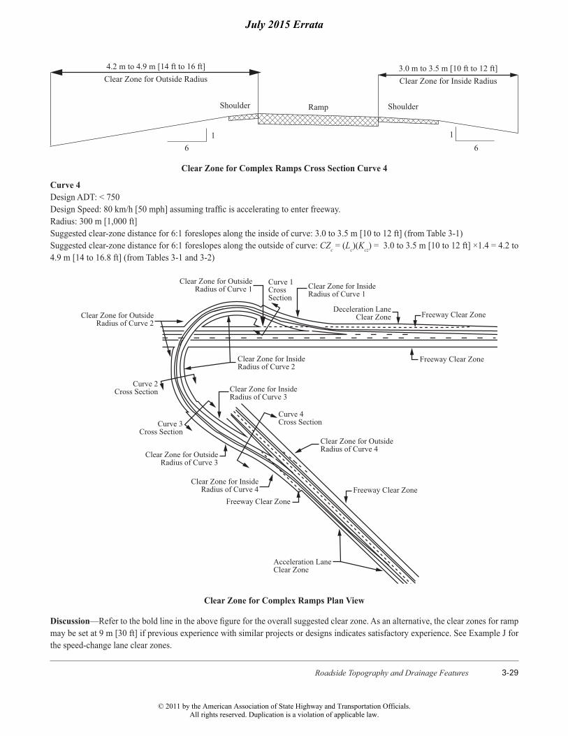
3.0 m to 3.5 m [10 ft to 12 ft]Clear Zone for Inside Radius
ShoulderRampShoulder
4.2 m to 4.9 m [14 ft to 16 ft]Clear Zone for Outside Radius
16
16
Clear Zone for Complex Ramps Cross Section Curve 4
Curve 4 Design ADT: < 750Design Speed: 80 km/h [50 mph] assuming traffic is accelerating to enter freeway.Radius: 300 m [1,000 ft]Suggested clear-zone distance for 6:1 foreslopes along the inside of curve: 3.0 to 3.5 m [10 to 12 ft] (from Table 3-1)Suggested clear-zone distance for 6:1 foreslopes along the outside of curve: CZc = (Lc)(Kcz) = 3.0 to 3.5 m [10 to 12 ft] ×1.4 = 4.2 to 4.9 m [14 to 16.8 ft] (from Tables 3-1 and 3-2)
Freeway Clear Zone
Freeway Clear Zone
Freeway Clear Zone
Deceleration Lane Clear Zone
Clear Zone for InsideRadius of Curve 1
Curve 1Cross Section
Clear Zone for OutsideRadius of Curve 1
Clear Zone for OutsideRadius of Curve 2
Curve 2Cross Section
Curve 3Cross Section
Clear Zone for OutsideRadius of Curve 3
Clear Zone for InsideRadius of Curve 4
Freeway Clear Zone
Acceleration Lane Clear Zone
Curve 4Cross Section
Clear Zone for OutsideRadius of Curve 4
Clear Zone for InsideRadius of Curve 2
Clear Zone for InsideRadius of Curve 3
Clear Zone for Complex Ramps Plan View
Discussion—Refer to the bold line in the above figure for the overall suggested clear zone. As an alternative, the clear zones for ramp may be set at 9 m [30 ft] if previous experience with similar projects or designs indicates satisfactory experience. See Example J for the speed-change lane clear zones.
July 2015 Errata
© 2011 by the American Association of State Highway and Transportation Officials.All rights reserved. Duplication is a violation of applicable law.

Roadside Design Guide5-12
Table 5-3. Roadside Barriers and NCHRP Report 350 Approved Test Levels
System Test Level FHWA Acceptance Letter
System Designation
Reference Section
FLEXIBLE SYSTEMS
W-Beam (Weak Post) 2 B-64 SGR02 5.4.1.3
Three-Strand Cable (Weak Post) 3 B-64 SGR01a and b 5.4.1.1
High-Tension Cable Barriers 3 and 4 Various Various 5.4.1.2
Modified W-Beam (Weak Post) 3 B-64 SGRO2 5.4.1.3
Ironwood Aesthetic Barrier 3 B-56, 56-A, and 56-B 5.4.1.4
SEMI-RIGID SYSTEMS
Steel Post with Steel Blockout 2 B-64 SGR04a 5.4.1.6
Box Beam (Weak Post) 3 B-64 SGR03 5.4.1.5
Steel or Wood Post with Wood or Plastic Blockout 3 B-64 SGR04a and b 5.4.1.6
NU-GUARD by Nucor Marion 3 and 4 B-162 and B-162-B 5.4.1.8
Trinity T-31 and Trinity Guardrail System 3 B-140 5.4.1.8
Gregory (GMS) 3 B-150 5.4.1.8
Midwest Guardrail System (MGS) 3 B-133 5.4.1.7
Blocked-out Thrie-Beam (Strong Post) 3 B-64 SGR09cSGR09a
5.4.1.9.1
Merritt Parkway Aesthetic Guardrail 3 B-38 5.4.1.10
Steel-Backed Timber Guardrail 2 and 3 B-64-D 5.4.1.11
Modified Thrie-Beam (Strong Post) 4 B-64 SGR09b 5.4.1.9.2
Trinity T-39 Non-Blocked-Out Thrie Beam 4 B-148 5.4.1.9.3
RIGID SYSTEMS (Concrete and Masonry)
Stone Masonry Wall/Precast Masonry Wall 3 B-64-D 5.4.1.14
New Jersey Safety-Shape Barrier 5.4.1.12
• 810 mm [32 in.] tall• 1070 mm [42 in.] tall
4 B-64 SGM11a 5.4.1.12
5 B-64 SGM11b 5.4.1.12
F–Shape Barrier 5.4.1.12
• 810 mm [32 in.]• 1070 mm [42 in.]
4 B-64 SGM10a 5.4.1.12
5 B-64 SGM10b 5.4.1.12
Vertical Concrete Barrier 5.4.1.12
• 810 mm [32 in.]• 1070 mm [42 in.]
4 B-64 5.4.1.12
5 B-64 5.4.1.12
Single Slope Barrier 5.4.1.12
• 810 mm [32 in.]• 1070 mm [42 in.]
4 B-17, B-45 5.4.1.12
5 Note 1 5.4.1.12
Ontario Tall Wall Median Barrier 5 B-19 SGM12 5.4.1.12
Note 1: The Single Slope Barriers were not tested to the TL-5 level but may be considered TL-5 barriers when cast in place or slip-formed if the dimensions, reinforcing, and foundation details are equivalent to designs that have been tested. See FHWA Acceptance Letter B-64.
July 2015 Errata
© 2011 by the American Association of State Highway and Transportation Officials.All rights reserved. Duplication is a violation of applicable law.
Roadside Design Guide5-42
The barrier-to-obstruction distance for fixed objects should not be less than the dynamic deflection of the barrier based on the ap-propriate test level. In some cases, the available space between the barrier and the object may not be adequate. In such cases, the barrier should be stiffened in advance of and alongside the fixed object. Commonly used methods to reduce deflection in a semi-rigid or flexible barrier system include reduced post spacing, increased post size, use of soil plates, intermediate anchorages, and stiffened rail elements. The effects on deflection of reduced post spacing are shown in Table 5-6 with the individual barrier descriptions. In some cases, a more rigid barrier type may be needed. Refer to Section 5.5.2 for additional details regarding the Zone of Intrusion in determining the barrier-to-obstacle clearance.
If an embankment is shielded, the barrier-to-embankment distance should be sufficient to provide adequate support for the posts to obtain proper operational characteristics of the barrier. However, limited test results indicate that the offset distance for embankments is not as critical as it is for rigid objects. A 0.6-m [2-ft] distance, as shown in Figure 5-33, is desirable for adequate post support, but may vary depending on the slope of the embankment, soil type, expected impact conditions, post cross section and embedment, and the type of barrier system. Increasing the embedment length of guardrail posts by 0.3 m [1 ft] or more can compensate for the reduced soil foundation support near the slope break point. A crash test was successfully conducted to NCHRP Report 350 TL-3 criteria with 2134 mm [7 ft.] long, W150 × 13.5 [W6 × 9] steel posts with standard routed wood blockouts when the posts were set at the hinge point of a 1V:2H slope. The posts were installed on 953-mm [3 ft-1-1/2 in.] centers. Other strong-post W-beam sys-tems that do not require the additional 0.6-m [2-ft] grading platform behind the posts have been developed or are in the process of being developed.
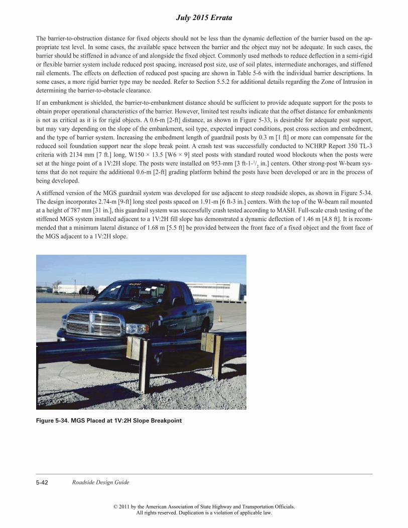
A stiffened version of the MGS guardrail system was developed for use adjacent to steep roadside slopes, as shown in Figure 5-34. The design incorporates 2.74-m [9-ft] long steel posts spaced on 1.91-m [6 ft-3 in.] centers. With the top of the W-beam rail mounted at a height of 787 mm [31 in.], this guardrail system was successfully crash tested according to MASH. Full-scale crash testing of the stiffened MGS system installed adjacent to a 1V:2H fill slope has demonstrated a dynamic deflection of 1.46 m [4.8 ft]. It is recom-mended that a minimum lateral distance of 1.68 m [5.5 ft] be provided between the front face of a fixed object and the front face of the MGS adjacent to a 1V:2H slope.
Figure 5-34. MGS Placed at 1V:2H Slope Breakpoint
July 2015 Errata
© 2011 by the American Association of State Highway and Transportation Officials.All rights reserved. Duplication is a violation of applicable law.
Roadside Barriers 5-43
5.6.2 Terrain Effects
Generally, acceptable impact conditions at the moment of impact occur when all of the wheels of the vehicle are on the ground and its suspension system is neither compressed nor extended. Conversely, terrain conditions between the traveled way and the barrier can have significant effects on the barrier’s impact performance.
Curbs and roadside slopes are two particular features that deserve special attention. A vehicle which traverses one of these features prior to impact may override the barrier if it is partially airborne at the moment of impact. Conversely, the vehicle may “submarine” under the rail element and snag on the support posts if it strikes the barrier too low. Limited research studies and computer simulations have provided some information on the dynamic behavior and trajectories of vehicles traversing curbs or slopes. The impact position of a car relative to a roadside barrier at a given lateral distance from a curb or slope is known for a portion of the multiple impact conditions (vehicle mass [weight], speed, and angle). These data are presented in the following two subsections.
5.6.2.1 Curbs
Section 3.4.1 addresses the use of curbs primarily as drainage control features and presents only very general guidelines concerning their use in conjunction with traffic barriers. When a vehicle strikes a curb, the trajectory of the vehicle depends upon several vari-ables: the size and suspension characteristics of the vehicle, its impact speed and angle, and the height and shape of the curb itself.
Crash tests have shown that use of most guardrail/curb combinations where high-speed, high-angle impacts are likely should be discouraged. However, the MGS and Trinity T-31™ barrier have been developed and approved to be used in conjunction with curbs. Where there are no feasible alternatives, the designer should consider using a sloping curb no higher than 100 mm [4 in.] and consider stiffening the guardrail to reduce potential deflection. Other measures that may improve performance are bolting a W-beam to the back of the posts, reducing post spacing, nesting the rail, or adding a rubrail. On lower-speed facilities, a vaulting potential still ex-ists, but since the risk of such an occurrence is lessened, a design change may not be cost-effective. A case-by-case analysis of each situation considering the anticipated speeds and consequences of vehicular penetration should be used. The layout of the barrier and curb should be considered by the designer.
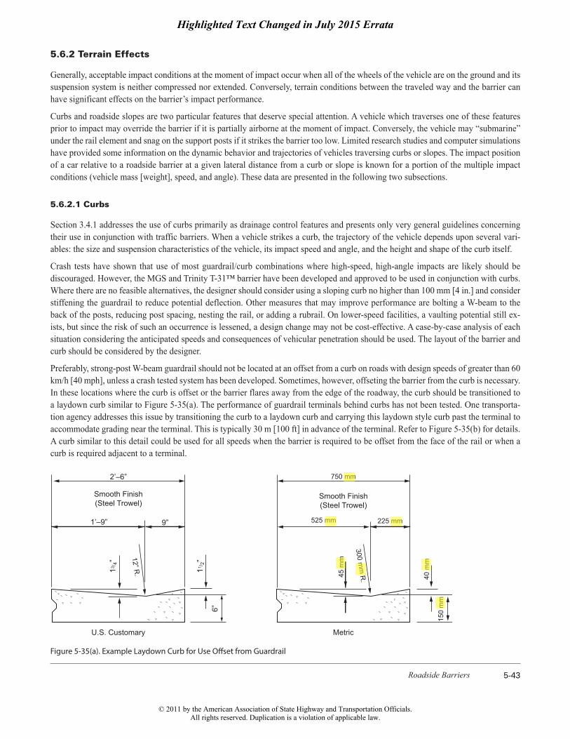
Preferably, strong-post W-beam guardrail should not be located at an offset from a curb on roads with design speeds of greater than 60 km/h [40 mph], unless a crash tested system has been developed. Sometimes, however, offseting the barrier from the curb is necessary. In these locations where the curb is offset or the barrier flares away from the edge of the roadway, the curb should be transitioned to a laydown curb similar to Figure 5-35(a). The performance of guardrail terminals behind curbs has not been tested. One transporta-tion agency addresses this issue by transitioning the curb to a laydown curb and carrying this laydown style curb past the terminal to accommodate grading near the terminal. This is typically 30 m [100 ft] in advance of the terminal. Refer to Figure 5-35(b) for details. A curb similar to this detail could be used for all speeds when the barrier is required to be offset from the face of the rail or when a curb is required adjacent to a terminal.
Smooth Finish(Steel Trowel)
U.S. Customary Metric
Smooth Finish(Steel Trowel)
1’–9” 9”
2’–6” 750 mm
525 mm 225 mm
300 mm
R. 40
mm
45 m
m
6”
150
mm
11/ 2”12” R
.13/ 4”
Figure 5-35(a). Example Laydown Curb for Use Offset from Guardrail
Highlighted Text Changed in July 2015 Errata
© 2011 by the American Association of State Highway and Transportation Officials.All rights reserved. Duplication is a violation of applicable law.
Roadside Barriers 5-49
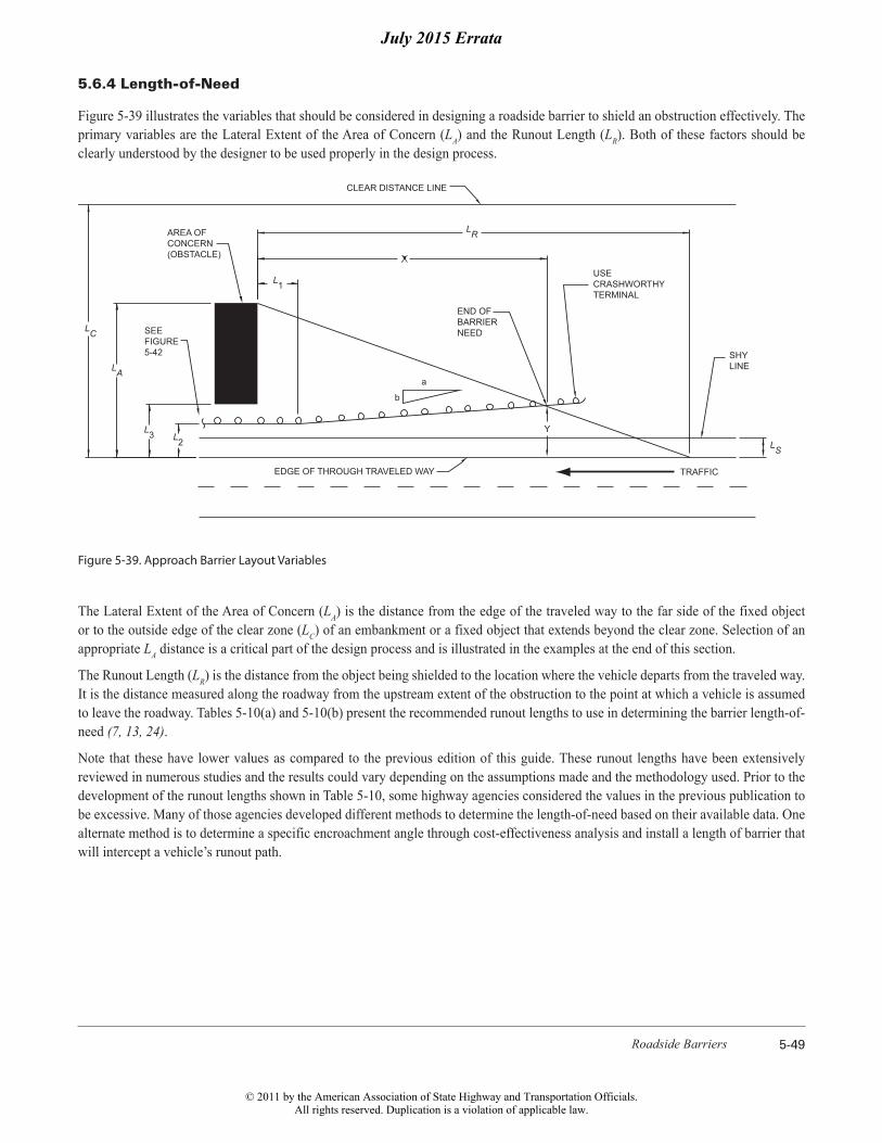
5.6.4 Length-of-Need
Figure 5-39 illustrates the variables that should be considered in designing a roadside barrier to shield an obstruction effectively. The primary variables are the Lateral Extent of the Area of Concern (LA) and the Runout Length (LR). Both of these factors should be clearly understood by the designer to be used properly in the design process.
LR
L1
a
b
LS
SHY LINE
TRAFFICEDGE OF THROUGH TRAVELED WAY
END OF BARRIERNEED
USECRASHWORTHYTERMINAL
AREA OFCONCERN(OBSTACLE)
SEEFIGURE5-42
CLEAR DISTANCE LINE
LA
LC
L2L3 Y
Figure 5-39. Approach Barrier Layout Variables
The Lateral Extent of the Area of Concern (LA) is the distance from the edge of the traveled way to the far side of the fixed object or to the outside edge of the clear zone (LC) of an embankment or a fixed object that extends beyond the clear zone. Selection of an appropriate LA distance is a critical part of the design process and is illustrated in the examples at the end of this section.
The Runout Length (LR) is the distance from the object being shielded to the location where the vehicle departs from the traveled way. It is the distance measured along the roadway from the upstream extent of the obstruction to the point at which a vehicle is assumed to leave the roadway. Tables 5-10(a) and 5-10(b) present the recommended runout lengths to use in determining the barrier length-of-need (7, 13, 24).
Note that these have lower values as compared to the previous edition of this guide. These runout lengths have been extensively reviewed in numerous studies and the results could vary depending on the assumptions made and the methodology used. Prior to the development of the runout lengths shown in Table 5-10, some highway agencies considered the values in the previous publication to be excessive. Many of those agencies developed different methods to determine the length-of-need based on their available data. One alternate method is to determine a specific encroachment angle through cost-effectiveness analysis and install a length of barrier that will intercept a vehicle’s runout path.
July 2015 Errata
© 2011 by the American Association of State Highway and Transportation Officials.All rights reserved. Duplication is a violation of applicable law.
Roadside Design Guide5-58
Transition 1V:3H to 1V:6H 1V:6H
Traffic
1.8 m (6’) Shoulder
LR = 88 m (290’)
LC = 8.5 m (28’)
L2 = 2.0 m (6.6’)
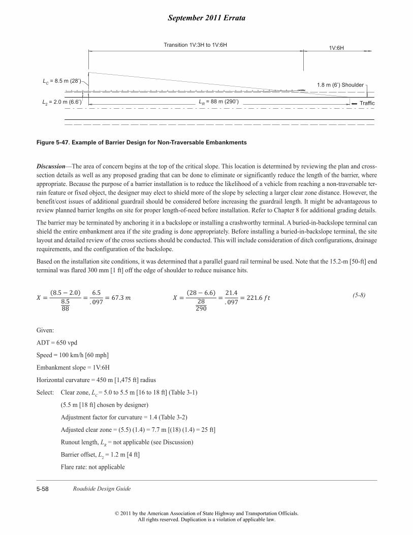
Figure 5-47. Example of Barrier Design for Non-Traversable Embankments
Discussion—The area of concern begins at the top of the critical slope. This location is determined by reviewing the plan and cross-section details as well as any proposed grading that can be done to eliminate or significantly reduce the length of the barrier, where appropriate. Because the purpose of a barrier installation is to reduce the likelihood of a vehicle from reaching a non-traversable ter-rain feature or fixed object, the designer may elect to shield more of the slope by selecting a larger clear zone distance. However, the benefit/cost issues of additional guardrail should be considered before increasing the guardrail length. It might be advantageous to review planned barrier lengths on site for proper length-of-need before installation. Refer to Chapter 8 for additional grading details.
The barrier may be terminated by anchoring it in a backslope or installing a crashworthy terminal. A buried-in-backslope terminal can shield the entire embankment area if the site grading is done appropriately. Before installing a buried-in-backslope terminal, the site layout and detailed review of the cross sections should be conducted. This will include consideration of ditch configurations, drainage requirements, and the configuration of the backslope.
Based on the installation site conditions, it was determined that a parallel guard rail terminal be used. Note that the 15.2-m [50-ft] end terminal was flared 300 mm [1 ft] off the edge of shoulder to reduce nuisance hits.
(5-8)
Given:
ADT = 650 vpd
Speed = 100 km/h [60 mph]
Embankment slope = 1V:6H
Horizontal curvature = 450 m [1,475 ft] radius
Select: Clear zone, LC = 5.0 to 5.5 m [16 to 18 ft] (Table 3-1)
(5.5 m [18 ft] chosen by designer)
Adjustment factor for curvature = 1.4 (Table 3-2)
Adjusted clear zone = (5.5) (1.4) = 7.7 m [(18) (1.4) = 25 ft]
Runout length, LR = not applicable (see Discussion)
Barrier offset, L2 = 1.2 m [4 ft]
Flare rate: not applicable
September 2011 Errata
© 2011 by the American Association of State Highway and Transportation Officials.All rights reserved. Duplication is a violation of applicable law.
Roadside Design Guide6-2
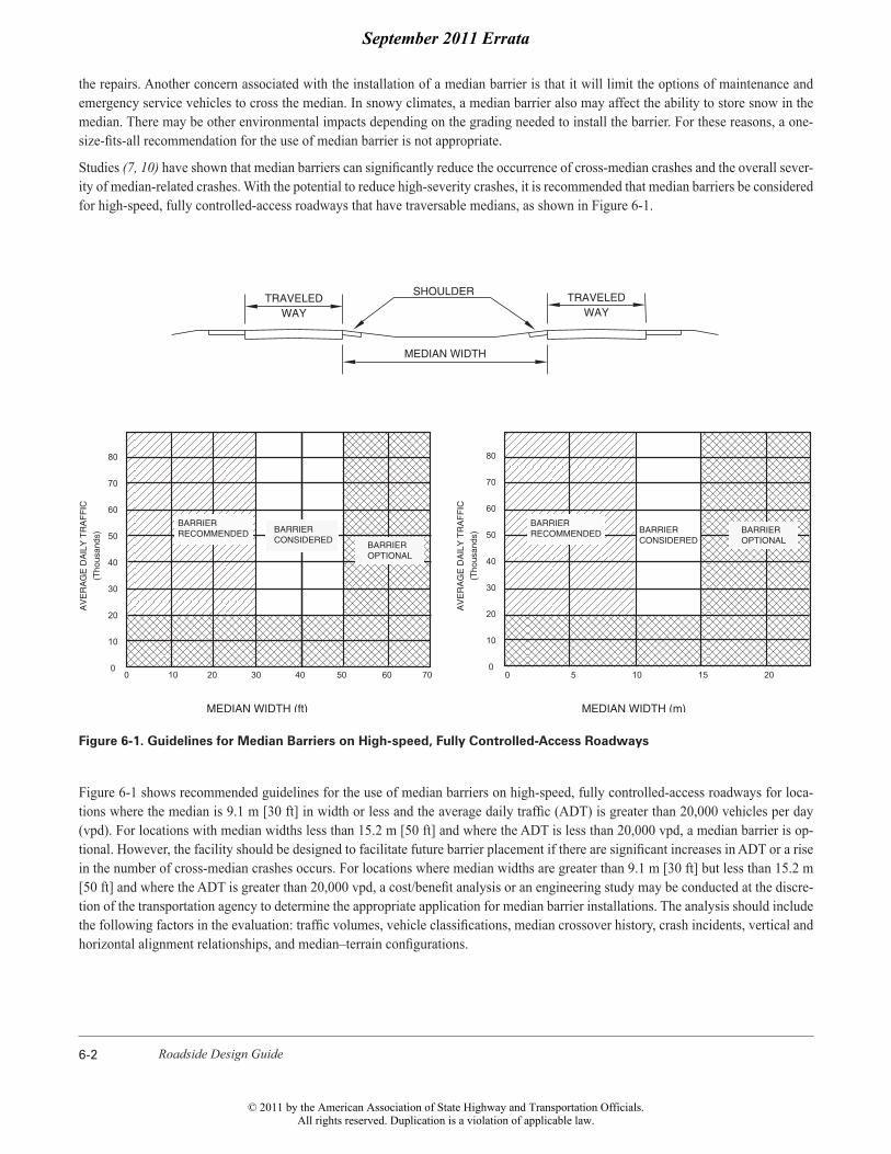
the repairs. Another concern associated with the installation of a median barrier is that it will limit the options of maintenance and emergency service vehicles to cross the median. In snowy climates, a median barrier also may affect the ability to store snow in the median. There may be other environmental impacts depending on the grading needed to install the barrier. For these reasons, a one-size-fits-all recommendation for the use of median barrier is not appropriate.
Studies (7, 10) have shown that median barriers can significantly reduce the occurrence of cross-median crashes and the overall sever-ity of median-related crashes. With the potential to reduce high-severity crashes, it is recommended that median barriers be considered for high-speed, fully controlled-access roadways that have traversable medians, as shown in Figure 6-1.
80
70
60
50
40
30
20
10
0
MEDIAN WIDTH (m)MEDIAN WIDTH (ft)
0 5 10 15 20
80
70
60
50
40
30
20
10
0
AV
ER
AG
E D
AIL
Y T
RA
FF
IC
(Tho
usan
ds)
0 10 20 30 40 50 60 70
(Tho
usan
ds)
AV
ER
AG
E D
AIL
Y T
RA
FF
IC
BARRIERCONSIDERED
MEDIAN WIDTH
WAYTRAVELEDSHOULDER
WAYTRAVELED
BARRIEROPTIONALBARRIER
OPTIONAL
BARRIERCONSIDERED
BARRIERRECOMMENDED
BARRIERRECOMMENDED
Figure 6-1. Guidelines for Median Barriers on High-speed, Fully Controlled-Access Roadways
Figure 6-1 shows recommended guidelines for the use of median barriers on high-speed, fully controlled-access roadways for loca-tions where the median is 9.1 m [30 ft] in width or less and the average daily traffic (ADT) is greater than 20,000 vehicles per day (vpd). For locations with median widths less than 15.2 m [50 ft] and where the ADT is less than 20,000 vpd, a median barrier is op-tional. However, the facility should be designed to facilitate future barrier placement if there are significant increases in ADT or a rise in the number of cross-median crashes occurs. For locations where median widths are greater than 9.1 m [30 ft] but less than 15.2 m [50 ft] and where the ADT is greater than 20,000 vpd, a cost/benefit analysis or an engineering study may be conducted at the discre-tion of the transportation agency to determine the appropriate application for median barrier installations. The analysis should include the following factors in the evaluation: traffic volumes, vehicle classifications, median crossover history, crash incidents, vertical and horizontal alignment relationships, and median–terrain configurations.
September 2011 Errata
© 2011 by the American Association of State Highway and Transportation Officials.All rights reserved. Duplication is a violation of applicable law.

Median Barriers 6-7
The high-tension systems also result in less damage to the barrier and, in many cases, the cables remain at the proper height after an impact that damages several posts. Although no manufacturer claims that their barrier remains functional in this condition, there may be a residual safety value under certain crash conditions. The posts can be installed in cast or driven sockets in the ground to facilitate removal and replacement.
There are currently five high-tension cable barrier systems that have been accepted by FHWA as meeting NCHRP Report 350, Test Level (TL) 3 conditions. Modified versions of all five systems have been successfully tested at the NCHRP Report 350 Test Level 4 condition and approved for 1V:6H or flatter slopes.
All of the systems also have been approved for limited use on 1V:4H slopes. Among the limitations is the fact that this configuration requires a TL-4 system that only functions at TL-3 because of the vehicle dynamics inherent with steeper grades. The systems’ lateral placement within the median also is limited to no farther than 1.2 m (4 ft) down the 1V: 4H slope for adjacent traffic impacts and no closer than 2.7 m (9 ft) from the ditch bottom for opposite-side impacts.
All of these systems use weak posts to support the cables. However, they each utilize a unique post design. The following are the cur-rently accepted high-tension cable barrier systems:
• Brifen Wire Rope Safety Fence—Manufactured by Brifen USA, Inc., the Brifen system uses three or four cables. One is placed in a slot on the post while the others intertwined between the posts (see Figure 6-4).
• The Cable Safety System (CASS™)—Manufactured by Trinity Industries, Inc., CASS uses three cables that are placed in a slot on the posts and separated by spacer blocks (see Figure 6-5).
• NU-CABLE™—Manufactured by the Nucor Steel Marion Inc., the NU-CABLE high-tension cable barrier system uses three or four cables attached to U-channel steel posts by unique hook bolts (see Figure 6-6).
• Blue Systems (Safence)—The Safence system is a three or four-cable design. For a median barrier, all four cables are cen-tered within the top portion of slotted posts (see Figure 6-7).
• Gibraltar Cable Barrier System—The Gibraltar Cable Barrier System uses C-posts to support three or four cables. A steel hairpin and lock plate are used to attach the cables to the posts (see Figure 6-8).
Figure 6-4. Brifen Wire Rope Safety Fence
September 2011 Errata 2
© 2011 by the American Association of State Highway and Transportation Officials.All rights reserved. Duplication is a violation of applicable law.

End Treatments (Anchorages, Terminals, and Crash Cushions) 8-9
8.3.6 Terminals for W-Beam Guardrail Systems
This section describes end terminals and their design criteria for specific W-beam guardrail systems. Table 8-2 lists these terminals with their respective information.
Table 8-2. Terminals for W-Beam Guardrail Systems
Terminal Test Level (TL)
FHWA Acceptance
Letter
System Designation Manufacturer Reference
Section
Buried-in-Backslope Terminal (Section 8.3.6.1)
Buried-in-Backslope Terminal 3CC-53
CC-53ANot Posted Generic 8.3.6.1
Flared Terminals (Section 8.3.6.2)
Eccentric Loader Terminal (ELT)
3CC-56
CC-56ANot Posted Generic 8.3.6.2.1
Modified Eccentric Loader Terminal (MELT)
2 CC-84 SEW05 Generic 8.3.6.2.2
Flared Energy-Absorbing Terminal (FLEAT™)
2 and 3 CC-46A, B, and C
SEW14a to b Road Systems, Inc. 8.3.6.2.3
3 CC-61, B, and C
Slotted Rail Terminal(SRT-350™)
3CC-31
CC-31ACC-72
SEW12 SEW11
Trinity Highway Products, LLC 8.3.6.2.4
X-Tension™ Guardrail End Terminal
3CC-91CC-102
Not Posted Barrier Systems, Inc. 8.3.6.2.5
Tangent Terminals (Section 8.3.6.3)
Extruder Terminal (ET-Plus™) 2 and 3 CC-12 thru CC-12Q Not Posted Trinity Highway Products, LLC 8.3.6.3.1
Extruder Terminal (ET-Plus™) with Collision Performance
Side Impact (CPSI)2 and 3 CC-81 Not Posted Trinity Highway Products, LLC 8.3.6.3.1
Sequential Kinking Terminal (SKT-350™ and SKT-LITE)
2 and 3CC-40A and B
CC-61A, B, and CSEW17a to c Road Systems, Inc. 8.3.6.3.2
X-Tension™ Guardrail End Terminal
3CC-91CC-102
Not Posted Barrier Systems, Inc. 8.3.6.3.3
787-mm [31-in.] Height Terminals (Section 8.3.6.4)
FLEAT-MGS™ 2 and 3CC-88CC-96
SEW15 Road Systems, Inc. 8.3.6.2.3
SRT-31™ 3 CC-100 Not Posted Trinity Highway Products, LLC 8.3.6.2.4
SKT-MGS™ and SKT-LITE
2 and 3CC-88CC-96
SEW18a to b Road Systems, Inc. 8.3.6.3.2
ET-Plus-31™ 3CC-94
CC-94ANot Posted Trinity Highway Products, LLC 8.3.6.3.1
Highlighted Text Changed in July 2015 Errata
© 2011 by the American Association of State Highway and Transportation Officials.All rights reserved. Duplication is a violation of applicable law.

End Treatments (Anchorages, Terminals, and Crash Cushions) 8-19
Figure 8-16. FLEAT Median Terminal (FLEAT-MT™)
Figure 8-17. X-Tension™ Median Attenuator System (X-MAS)
8.3.7 Terminals for Box-Beam Guardrail
This section describes the terminals for the box beam guardrail system discussed in Chapter 5. Table 8-4 lists these terminals with their respective information.
July 2015 Errata
© 2011 by the American Association of State Highway and Transportation Officials.All rights reserved. Duplication is a violation of applicable law.

End Treatments (Anchorages, Terminals, and Crash Cushions) 8-23
8.4.2 Crash Cushions Based on Work-Energy Principle
Tables 8-5, 8-6, and 8-7 summarize the crash cushions that have been successfully tested in accordance with TL-1, TL-2, or TL-3 con-ditions, under either NCHRP Report 350 or MASH procedures, and are discussed in the following subsections. It should be noted that some of these devices can be and have been used as roadside barrier terminals, but such use generally is not considered cost-effective.
Manufacturers design and market a variety of crash cushions that offer different tradeoffs among initial costs, repair and restoration costs, and maintenance characteristics. These devices can be classified as sacrificial, reusable, or low-maintenance and/or self-restor-ing, depending on the maintenance characteristics to restore performance following an impact by a vehicle. Depending on the known or expected crash frequency or severity at a particular location, life-cycle costs of various devices can be estimated and used as a factor in choosing a device at that site or similar ones.
While terminals are mostly designed for locations where traffic is found only on one side of a device, crash cushions often are placed in medians or at exit gores on freeways where traffic is on both sides. Highway designers need to account for another feature of crash cushions: products that are unidirectional, which refers to traffic traveling in the same direction on both sides of the crash cushion (e.g., as at a gore), and bidirectional, which refers to traffic moving in opposite directions on either side of the device.
Another feature the designer should understand is that several crash cushion vendors offer product lines referred to as product fami-lies. Products within a family have the same general characteristics but are rated at different speeds and widths. Other product lines do not have this divisibility.
Most crash cushions should be appropriately and adequately installed to a foundation pad and be sufficiently connected to a rigid backup. All systems have their own designs and products should be installed in accordance with the manufacturer’s recommendations.
When a crash cushion is used in conjunction with a longitudinal barrier system, the designer should specify an appropriate transition section to positively connect the crash cushion with the longitudinal barrier system. In most situations in which the crash cushion is not directly attached to the object being shielded, a stand-alone backup anchorage is necessary. Check with the product manufacturer to obtain their recommended designs.
8.4.2.1 Sacrificial Crash Cushions
Sacrificial crash cushions are crashworthy roadside safety devices designed for a single impact. Most of the systems absorb impact energy by crushing the steel rail elements. Other devices have expendable plastic cartridges containing foam, sand, or water, which also absorb energy by crushing. These systems’ major components are destroyed in impacts, but many of the other parts can be reused. These devices generally offer low initial costs and can be cost-effective if placed in locations where the designer expects infrequent crashes to occur. Table 8-5 lists many of the available crash cushions in this category.
Table 8-5. Sacrificial Crash Cushions
Crash Cushion Test LevelFHWA
Acceptance Letter
System Designation Manufacturer Reference
Section
Thrie-Beam Bullnose Guardrail System 3 CC-68 SET03 Generic 8.4.2.1.1
ABSORB 350® 32
CC-66,A and B
SCI11 Barrier Systems, Inc. 8.4.2.1.2
Advanced Dynamic Impact Extension Module (ADIEM™)
3 CC-38 SCI09Trinity Highway Products,
LLC8.4.2.1.3
BEAT-SSCC™ 3CC-69B, D,
and ESC113A-B Road Systems, Inc. 8.4.2.1.4
July 2015 Errata
© 2011 by the American Association of State Highway and Transportation Officials.All rights reserved. Duplication is a violation of applicable law.

End Treatments (Anchorages, Terminals, and Crash Cushions) 8-29
Figure 8-27. QuadGuard® Crash Cushion
8.4.2.2.2 Universal TAU-II® Family
The name Universal TAU-II® refers to a family of proprietary, bi-directional, energy-absorbing crash cushions that are rated to various speeds and hazard widths while using a small group of common parts. Expandable bulkheads allow narrow and wide widths ranging from 760 mm to 2.6 m [2 ft, 6 in. to 8 ft, 6 in.] in 150-mm [6-in.] increments. Greater widths can be accomplished by adding additional standard thrie-beam panels. Speed ratings range from 50 km/h to 120 km/h [31 mph to 75 mph]. The crash cushions consist of two types of expendable energy-absorbing cartridges separated by steel diaphragms as well as thrie-beam sliding side panels. Figure 8-28 shows this four-bay system.
Figure 8-28. TAU-II Crash Cushion
July 2015 Errata
© 2011 by the American Association of State Highway and Transportation Officials.All rights reserved. Duplication is a violation of applicable law.

End Treatments (Anchorages, Terminals, and Crash Cushions) 8-31
8.4.2.3 Low-Maintenance and/or Self-Restoring Crash Cushions
The crash cushions shown in Table 8-7 typically are considered for use at locations where a high frequency of impacts may be ex-pected. The category of “Low Maintenance and/or Self Restoring” crash cushions includes those devices that either suffer very little, if any, damage upon impact and are easily pulled back into their full operating condition, or they partially rebound after an impact and may only need an inspection to ensure that no parts have been damaged or misaligned. Although some crash cushions can still function and save lives after being struck once, no device is completely maintenance free. It is important to note that devices in this category may be low-maintenace, self-restoring, or both. Inclusion of a device in this combined category does not imply that the de-vice has both attributes. Often these products are installed in high-speed, high-traffic volume ramps or medians to reduce the exposure of maintenance workers to the traffic.
Table 8-7. Low-Maintenance and/or Self-Restoring Crash Cushions
Crash Cushion Test LevelFHWA
Acceptance Letter
System Designation Manufacturer Reference
Section
Compressor 3 CC-95 Not Posted Traffix Devices 8.4.2.3.1
EASI-CELL 1 CC-71 SCI 15Energy Absorption
Systems, Inc.8.4.2.3.2
Hybrid Energy Absorbing Reusable Terminal (HEART™)
3CC-89
CC-89ANot Posted
Trinity Highway Products, LLC
8.4.2.3.3
QuadGuard Elite7-bay unit8-bay unit9-bay unit
233
CC-57 CC-57ACC-57B
SCT02eEnergy Absorption
Systems, Inc.8.4.2.3.4
QuadGuard LMC11-bay unit
3 CC-43 SCT02fEnergy Absorption
Systems, Inc.8.4.2.3.5
Reusable Energy Absorbing Crash Terminal (REACT 350®)
4-cylinder array9-cylinder array
23
CC-26,A-ICC-50,A-B, CC-73,A-C
SCI16a-bEnergy Absorption
Systems, Inc.8.4.2.3.6
Smart Cushion Innovations (SCI)SCI-70GMSCI-100GM
23
CC-85 A and B SCI17a and b SCI Products, Inc. 8.4.2.3.7
8.4.2.3.1 Compressor™ Attenuator
The Compressor Attenuator, shown in Figure 8-31, is a proprietary, unidirectional, energy-absorbing crash cushion. It consists of high-density polyethylene (HDPE) attenuator modules designed to efficiently absorb energy in a relatively short distance. The modules are mounted on a proprietary UNI-BASE™, which allows the unit to be installed quickly without the need for field assembly. The telescoping high-strength steel side panels redirect side impacts while protecting the absorbing modules from incidental damage. The unit is designed to take repeated impacts without any additional recovery procedures and with minimal or no repairs.
July 2015 Errata
© 2011 by the American Association of State Highway and Transportation Officials.All rights reserved. Duplication is a violation of applicable law.

Roadside Design Guide8-32
Figure 8-31. Compressor Attenuator
8.4.2.3.2 EASI-CELL® Cluster
The EASI-CELL® cluster system is a unidirectional, low-maintenance and self-restoring crash cushion designed for ar-eas where space is limited and traffic speeds do not exceed 50 km/h [31 mph]. Hazards in these areas include tollbooths, util-ity poles, railroad crossing signals, and traffic signals. The system consists of a series of interconnected HDPE cyl-inders that anchor to the hazard on a concrete transition or a rigid steel backup structure, as shown in Figure 8-32.
Figure 8-32. EASI-CELL Cluster®
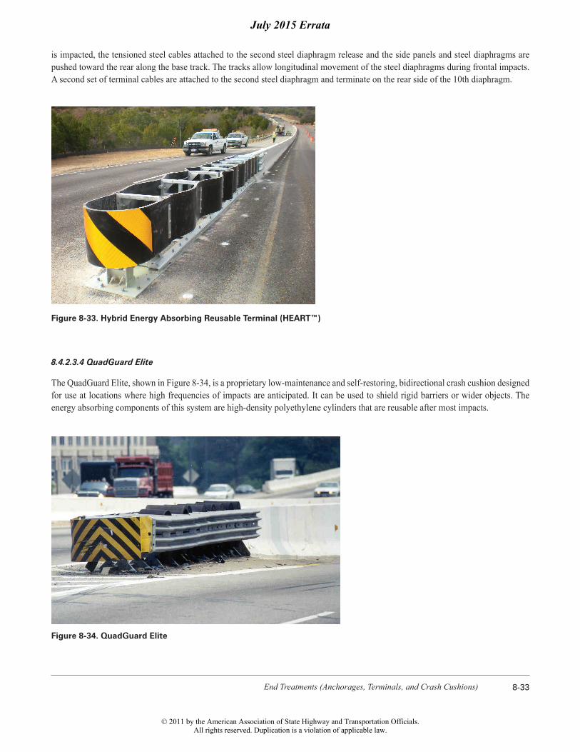
8.4.2.3.3 Hybrid Energy Absorbing Reusable Terminal (HEART™)
The HEART™ is a proprietary, energy-absorbing, bidirectional crash cushion that consists of three hinged high-molecular weight/high-density polyethylene panels along each side connected to steel diaphragms mounted on tubular steel tracks, as shown in Figure 8-33. A curved nose panel consisting of a high-molecular weight/high-density polyethylene is mounted on the first steel diaphragm. A tensioned cable is attached to the upper release post and to the second steel diaphragm on each side. When the upper release post
July 2015 Errata
© 2011 by the American Association of State Highway and Transportation Officials.All rights reserved. Duplication is a violation of applicable law.
End Treatments (Anchorages, Terminals, and Crash Cushions) 8-33
is impacted, the tensioned steel cables attached to the second steel diaphragm release and the side panels and steel diaphragms are pushed toward the rear along the base track. The tracks allow longitudinal movement of the steel diaphragms during frontal impacts. A second set of terminal cables are attached to the second steel diaphragm and terminate on the rear side of the 10th diaphragm.
Figure 8-33. Hybrid Energy Absorbing Reusable Terminal (HEART™)
8.4.2.3.4 QuadGuard Elite
The QuadGuard Elite, shown in Figure 8-34, is a proprietary low-maintenance and self-restoring, bidirectional crash cushion designed for use at locations where high frequencies of impacts are anticipated. It can be used to shield rigid barriers or wider objects. The energy absorbing components of this system are high-density polyethylene cylinders that are reusable after most impacts.
Figure 8-34. QuadGuard Elite
July 2015 Errata
© 2011 by the American Association of State Highway and Transportation Officials.All rights reserved. Duplication is a violation of applicable law.

Roadside Design Guide8-48
Table 8-12. Comparative Maintenance Characteristics
Sacrificial Crash Cushions
Crash Cushion Regular Maintenance Crash Maintenance Material Inventory
Thrie-Beam Bullnose Guardrail System
Can be inspected on a drive-by. Cable tension should be checked periodically.
Rail elements and posts should be replaced. Cables and foundation tubes are normally reusable.
Slotted thrie-beam rail elements and wood posts.
ABSORB 350® Normally can be inspected on a drive-by. Periodic on-site inspections should be performed to be certain that all parts are properly connected. Need to check water level. When winterized, check deicing agent.
Nose-piece and damaged energy-ab-sorbing elements should be replaced.
Replacement nosepiece, energy-absorbing elements, and fluid supply. Other parts per manufacturer’s recommendation.
ADIEM™ Modules should be closely inspected for damage.
Damaged concrete modules should be replaced. Damaged covers also should be replaced. Most other parts normally are reusable.
Replacement concrete modules, cov-ers, and other parts per the manufac-turer’s recommendation.
BEAT-SSCC™ Normally can be inspected on a drive-by. Periodic on-site inspections should be performed to be certain that all parts are properly connected and anchor cable is not slack.
Damaged tubes and posts should be replaced. Impact head is normally reusable.
End tube, second tube, breakaway posts.
BEAT-BP™ Normally can be inspected on a drive-by. Periodic on-site inspections should be performed to be certain that all parts are properly connected and anchor cable is not slack.
Damaged tubes and posts should be replaced. Impact head is normally reusable.
End tube, second tube, standard line tubes, breakaway posts, and standard line posts.
QUADTREND 350®
As this device uses sand-filled contain-ers, there is concern for freezing of sand in cold climates. See Section 8.4.3 for more information.
Most major components should be reusable after a crash.
Spare parts per manufacturer’s recommendation.
NCIAS Can be inspected on a drive-by. Crushed units should be removed from site; minor damage can be repaired on-site by jacking.
Spare cylinders to replace badly damaged units.
Sand-Filled Barrels
Can be inspected on a drive-by for external damage. If lids are not riveted on, sand content should be checked periodically. See Section 8.4.3 for information on using sand-filled barrels in cold climates.
Individual sand barrels should be re-placed after a crash; units damaged by nuisance hits also should be replaced. Debris should be removed from the site.
Spare barrels, sand support inserts, and lids; supply of sand.
Reusable Crash Cushions
QuadGuard® Normally can be inspected on a drive-by; missing or displaced cartridges can be readily noted. Should be periodical-ly inspected on-site to be certain that all parts are properly connected.
Nose, expended cartridges, and damaged fender panels should be replaced. Unit should be repositioned.
Spare cartridges, nose units, fender panels, and other parts per manufacturer’s recommendation.
Universal TAU-II™ Family
Normally can be inspected on a drive-by. Periodic on-site inspections should be performed to be certain that all parts are properly connected.
After a frontal impact, the system can be pulled out to restore the proper length. Replace damaged cartridges. During some side impacts, the sliding panels may be damaged.
Cartridges, sliding panels, pipe panel mounts, and nose pieces per manufacturer’s recommendations.
February 2012 Errata
© 2011 by the American Association of State Highway and Transportation Officials.All rights reserved. Duplication is a violation of applicable law.

End Treatments (Anchorages, Terminals, and Crash Cushions) 8-49
TRACC™ Normally can be inspected on a drive-by. Periodic on-site inspections should be performed to be certain that all parts are properly connected.
The rip plates need replacement. Newer versions of the TRACC eliminate need for extensive disassembly. The nose and fender panels also may need replacement.
Replacement rip plates, nose sections, fender panels, and other replacement parts per manufacturer’s recommendation.
QUEST® Normally can be drive-by inspected. Periodic on-site inspections should be performed to be certain that all parts are properly connected.
The nose, fender panels, and energy-absorbing rails or tubes need replace-ment after impacts. Open design allows for easy repair.
The nose, fender panels, and energy-absorbing rails or tubes and other parts per manufacturer’s recommendations.
Low Maintenance and/or Self-Restoring Crash Cushions
Crash Cushion Regular Maintenance Crash Maintenance Material Inventory
Compressor Normally can be inspected on a drive-by.
This unit is designed to take repeated impacts without any additional recov-ery procedures and with minimal or no repairs.
Spare parts per manufacturer’s recommendation.
EASI-CELL® Normally can be inspected on a drive-by. Plastic cylinders may deteriorate after several years of exposure to the elements.
This unit is designed to withstand mul-tiple impacts without cylinder replace-ment. All cylinders need to be replaced when the minor axis of the cylinders in the rear most row measures 230 mm [9 in.] or less.
Spare parts per manufacturer’s recommendation.
HEART™ Normally can be inspected on a drive-by.
Repair will depend on the severity of the impact. Minor side impacts may require no repair. End-on impacts may require only pulling the system back into place and replacing the nose bolt.
Spare parts per manufacturer’s recommendation.
QuadGuard LMC and Elite
Normally can be inspected on a drive-by. Periodic on-site inspections should be performed to be certain that all parts are properly connected.
Much of unit is reusable after a crash. Unit tends to self-restore to some ex-tent but should be evaluated after each impact. Unit may need to be reposi-tioned. When diameter of last cartridge becomes less than 660 mm [26 in.], all cartridges should be replaced.
Fender panels and other replacement parts per manufacturer’s recommendation.
REACT 350® Can be inspected on a drive-by. The system is considered fully reus-able. Repositioning is normally all that is needed after an impact. After side impacts, inspect stabilizer rods. If the cylinders cannot be restored to 90 percent of the original diameter, they should be replaced.
Spare parts per manufacturer’s recommendation.
Smart CushionSCI
Can be inspected on a drive-by for external damage. If the frontal collapse has been initiated, the unit should be inspected and reset.
The system will need two shear bolts and possibly a new delineator plate under design criteria impacts.
Shear bolts and delineator panel.
Table 8-12. Comparative Maintenance Characteristics (continued)
February 2012 Errata
© 2011 by the American Association of State Highway and Transportation Officials.All rights reserved. Duplication is a violation of applicable law.

Roadside Design Guide10-10
tacles. Buffer strips may be either planted or paved, and they are encouraged for use between urban roadways and their companion sidewalks.
Figure 10-4 depicts the recommended placement of roadside objects in a buffer strip 1.2 m [4 ft] wide or less. Figure 10-5 demon-strates recommended roadside object placement when the buffer strip width exceeds 1.2 m [4 ft]. Table 10-5 describes common strate-gies for eliminating or minimizing motor vehicle–pedestrian crashes at roadside locations.
Figure 10-4. Landscape and Rigid Object Placement for Buffer Strip Widths ≤1.2 m [4 ft]
Figure 10-5. Landscape and Rigid Object Placement for Buffer Strip Widths >1.2 m [4 ft]
Highlighted Text Changed in July 2015 Errata
© 2011 by the American Association of State Highway and Transportation Officials.All rights reserved. Duplication is a violation of applicable law.

Erecting Mailboxes on Streets and Highways 11-7
surface treatment course to accommodate multiple patron use. Special measures also may be needed where highway traffic conditions encourage hard braking or high acceleration by vehicles entering or exiting the mailbox turnout.
Edge dropoffs often are found at rural mailbox locations. The daily use by the delivery vehicles may loosen the soil at the edge of the pavement. When the soil at the edge is eroded, a drop of 100 mm [4 in.] or more may result. These edge dropoffs can make it difficult for drivers to safely return to the pavement if the vehicle strays onto the unstable soil. The use of paved turnouts is one solution. An-other approach is a recent paving innovation called the Safety Edge, which shapes the edge of the traveled way into a 30 degree angle rather than a vertical drop. This new angle is optimal in allowing motorists to return their vehicle to the pavement without overcor-recting or losing control.
Drivers usually are required to slow their vehicles in traffic, which increases the risk of a crash. The ideal way to minimize this risk is to provide a speed-change lane. A wide surface-treated shoulder is ideal for this purpose. Unfortunately, suitable shoulders are not available at most mailbox turnout locations and it would be far too expensive to provide shoulders or turnouts that would allow a speed change outside the traveled way. Figure 11-5 presents a mailbox turnout layout considered appropriate for different traffic conditions.
The minimum space needed for maneuvering to a parallel position in and out of traffic also is shown in Figure 11-5. However, when only the minimum space is provided, the typical driver probably would slow considerably before starting into the low-speed turnout. This tendency renders such minimum space unsuitable for high-speed highways where driver expectancy does not include such slow-moving traffic.
Before entering a 2.4-m [8-ft] wide turnout with a 20:1 taper for high-speed traffic, as shown in Figure 11-5, a driver probably would not slow as much before clearing the traveled way. Although this is not an ideal exit maneuver, it probably would not create an unac-ceptable hazard on most rural highways for the few stops generated by a single mailbox.
Increasing the width of the turnout to 3.6 m [12 ft] and maintaining the 20:1 taper rate suggested in Figure 11-5 would induce a driver using the turnout to enter it at a fair rate of speed, but it will not be as fast as the through speed. Although this still is not ideal, it should be acceptable for most sites. The exception may be found on highways operating at high speeds and carrying more than 3,000 vehicles per day, with a high percentage of them on long trips. For these conditions, mail stops should be kept to a minimum and consideration should be given to providing shoulders or turnouts at the mail stops to facilitate greater speed-change opportunities outside the traffic stream.
The tapers shown in Figure 11-5 represent theoretical layouts. It may be more practical to square the ends of the turnout or to provide a stepped layout by strengthening and widening the shoulder to the full width of the turnout for the entire length of the taper. It also may be simpler to construct a continuous turnout-width shoulder rather than individual turnouts where mailbox turnouts are closely spaced.
Travel
Direction of
* = For Mailbox Face Offset, see Table 11-1, 0 mm to 300 mm [0” to 12”].
5 m MIN. 2 m MIN.
[6’–7”] MIN.[16’–5”] MIN.
2:5:1 Taper For LS*
W = For Suggested Widths, see Table 11-1.
W
*
MAILBOXES = For Mailbox Spacing and Variable Length, see Section 11.2.4, Mailbox Support and Attachment Design.
HS = For Roads Carrying High-Speed Traffic.LS = A Minimum Design for Roads Carrying Low-Speed Traffic and for Local and Collector Roads.
20:1 Taper For HS
4:1Taper For LS
Edge of Paved Turnout
Edge of Paved Shoulder
VARIABLE
MAILBOXES
12:1 Taper For HS
Edge of Traveled Way
Figure 11-5. Mailbox Turnout
January 2012 Errata
© 2011 by the American Association of State Highway and Transportation Officials.All rights reserved. Duplication is a violation of applicable law.

G-1Glossary
Glossary
Adjacent Grading—Adjacent grading refers to the area on which the terminal is installed and the area immediately behind it. Advance Grading—Advance grading refers to the area over which a vehicle may travel before any contact with a barrier terminal is made.
Anchorage— A device which anchors a flexible or semi-rigid barrier to the ground so as to develop the barrier’s tensile strength during an impact. Anchorages differ from terminals in that they are not considered crashworthy.
Area of Concern—An object or roadside condition that may warrant safety treatment.
Barricade—A device which provides a visual indicator of a hazardous location or the desired path a motorist should take. It is not intended to contain or redirect an errant vehicle.
Barrier—A device which provides a physical limitation through which a vehicle would not normally pass. It is intended to contain or redirect an errant vehicle.
Bi-directional—For the purposes of classifying crash cushions, bi-directional describes the capability of a crash cushion to safely operate in the median of a divided highway or on an undivided roadway, where it will be exposed to impacts from two different direc-tions of traffic. A bi-directional crash cushion is also a uni-directional crash cushion. A crash cushion is considered to be bi-directional when it has been qualified through a reverse-direction crash test.
Breakaway—A design feature which allows a device such as a sign, luminaire, or traffic signal support to yield or separate upon im-pact. The release mechanism may be a slip plane, plastic hinges, fracture elements, or a combination of these.
Bridge Railing—A longitudinal barrier whose primary function is to prevent an errant vehicle from going over the side of the bridge structure.
Clearance—Lateral distance from edge of traveled way to a roadside object or feature.
Clear Runout Area—The area at the toe of a non-recoverable slope available for safe use by an errant vehicle.
Clear Zone—The unobstructed, traversable area provided beyond the edge of the through traveled way for the recovery of errant vehicles. The clear zone includes shoulders, bike lanes, and auxiliary lanes, except those auxiliary lanes that function like through lanes.
September 2011 Errata
© 2011 by the American Association of State Highway and Transportation Officials.All rights reserved. Duplication is a violation of applicable law.