aashto guide specifications for lrfd seismic bridge design ... · aashto lrfd bridge design...
TRANSCRIPT

ATTACHMENT B - 2007 AGENDA ITEM 7 – T-3
Proposed
AASHTO Guide Specifications for LRFD SeismicBridge Design
Subcommittee for Seismic Effects on BridgesT-3
Prepared by:
Roy A. ImbsenImbsen Consulting
May 2007

SECTION 1: INTRODUCTION
TABLE OF CONTENTS
1-i
1.1 BACKGROUND ................................................................................................................................................. 1-11.2 PROJECT ORGANIZATION ............................................................................................................................. 1-3
1.2.1 Technical Review Team............................................................................................................................. 1-31.2.2 Project Direction from AASHTO T-3 ....................................................................................................... 1-41.2.3 Technical Assistance Agreement Between AASHTO and USGS.............................................................. 1-5
1.3 FLOW Charts....................................................................................................................................................... 1-6
TO BE UPDATED BY AASHTO PUBLICATIONS


SECTION 1
INTRODUCTION
1-1
1.1 BACKGROUND C1.1
TheAASHTOGuide Specifications for LRFDSeismicBridge Design is established in accordance with theNCHRP 20-07/Task 193 Task 6 Report. Task 6 containsfive (5) Sections corresponding to Tasks 1 to 5 as follows:
SECTION 1 includes a review of the pertinentdocuments and information that were available.
SECTION 2 presents the justification for the 1000-year return period (which is approximately equivalent to a7% probability of exceedance in 75 years) asrecommended for the seismic design of highway bridges.
SECTION 3 includes a description of how the “noanalysis” zone is expanded and how this expansion isincorporated into the displacement based approach.
SECTION 4 describes the two alternative approachesavailable for the design of highway bridges with steelsuperstructures and concludes with a recommendation touse a force based approach for steel superstructures.
SECTION 5 describes the recommended procedurefor liquefaction design to be used for highway bridges.This aspect of the design is influenced by therecommended design event and the no analysis zonecovered in Tasks 2 and 3, respectively. Therecommendations proposed are made taking into accountthe outcome of these two tasks for Seismic DesignCategory D.
The following recommendations are documented:
Task 2
� Adopt the 7% in 75 years design event fordevelopment of a design spectrum.
� Ensure sufficient conservatism (1.5 safety factor)for minimum support length requirement. Thisconservatism is needed to accommodate the fullcapacity of the plastic hinging mechanism of thebridge system. This conservatism shall beembedded in the specifications to addressunseating vulnerability. At a minimum it isrecommended to embed this safety factor for sitesoutside of California.
� Partition Seismic Design Categories (SDC’s) intofour categories and proceedwith the developmentof analytical bounds using the 7% in 75 yearsdesign event.
This commentary is included to provide additionalinformation to clarify and explain the technical basis forthe specifications provided in theGuide Specifications forLRFD Seismic Bridge Design. These specifications are forthe design of new bridges
The term “shall” denotes a requirement forcompliance with these Specifications.
The term “should” indicates a strong preference for agiven criterion.
The term “may” indicates a criterion that is usable, butother local and suitably documented, verified, andapproved criterion may also be used in amanner consistentwith the LRFD approach to bridge design.
The term “recommended” is used to give guidancebased on past experiences. Seismic design is a developingfield of engineering, which has not been uniformly appliedto all bridge types and thus the experiences gained to dateon only a particular type are included as recommendations.

1-2 AASHTO GUIDE SPECIFICATIONS FOR LRFDSEISMIC BRIDGE DESIGN
Task 3
Establish four Seismic Design Categories with thefollowing requirements:
� SDC Aa. No Displacement Capacity Check Neededb. No Capacity Design Requiredc. SDC AMinimum Requirements
� SDC Bd. Implicit Displacement Capacity Check
Required (i.e., use a Closed Form SolutionFormula)
e. No Capacity Design Requiredf. SDC B Level of Detailing
� SDC Ca. Implicit Displacement Capacity Check
Requiredb. Capacity Design Requiredc. SDC C Level of Detailing
� SDC Dd. Pushover Analysis Requirede. Capacity Design Requiredf. SDC D Level of Detailing
Task 4
Recommended the following for SDC C & D:
� Adopt AISC LRFD Specifications for design ofsingle-angle members and members with stitchwelds.
� Allow for three types of a bridge structuralsystem as adopted in SCDOT Specifications.
Type 1 – Design a ductile substructure withan essentially elastic superstructure.
Type 2 – Design an essentially elasticsubstructure with a ductile superstructure.
Type 3 – Design an elastic superstructure andsubstructure with a fusing mechanism at theinterface between the superstructure and thesubstructure.
� Adopt a force reduction factor of 3 for design ofnormal end cross-frame.
� Adopt NCHRP 12-49 for design of “Ductile End-Diaphragm” where a force reduction factorgreater than 3 is desired.

SECTION 1: INTRODUCTION 1-3
Task 5
The following list highlights the main proposedliquefaction design requirements:
� Liquefaction design requirements are applicableto SDC D.
� Liquefaction design requirements are dependenton the mean magnitude for the 7% Probability ofExceedance in 75-year event and the normalizedStandard Penetration Test (SPT) blow count[(N1)60].
� If liquefaction occurs, then the bridge shall bedesigned and analyzed for the Liquefied andNon-Liquefied configurations.
Detailed design requirements and recommendationsfor lateral flow have not yet reached a level ofdevelopment suitable for inclusion in this document.However, limited information and guidance on lateral flowis provided.
1.2 PROJECT ORGANIZATION
The NCHRP Project was organized to assist theAASHTO T-3 Subcommittee for Seismic Design ofBridges to complete another step towards producingLRFD seismic design provisions for inclusion into theAASHTO LRFD Bridge Design Specifications. The T-3Subcommittee defined very specific tasks as described inArticle 1.1 above that it envisioned were needed tosupplement the existing completed efforts (i.e., AASHTODivision I-A, NCHRP 12-49 Guidelines, SCDOTSpecifications, Caltrans Seismic Design Criteria,NYDOTSeismic Intensity Maps and ATC-32) to yield aspecification for AASHTO which can be implemented.The tasks have now been completed by TRC/Imbsen &Associates, Inc. under the direction of the T-3Subcommittee and the assistance of their Board ofReviewers to yield a stand-alone Guide Specification thatcan be evaluated byAASHTO and considered for adoptingin 2007. This project was completed by ImbsenConsultingunder a subcontract with TRC/Imbsen & Associates, Inc.
1.2.1 Technical Review Team
The final stages for completing the GuideSpecifications contained herein encompassed two primarytasks. Several states across the U.S. performed trial bridgedesigns using preliminary drafts. The trial design bridgeconfigurations and soil types employed were typical foreach of the participating states. After completion of thesetrial designs, a technical team was formed whichcooperatively addressed questions, concerns and technicalissues in order to bring theGuide Specifications into their

1-4 AASHTO GUIDE SPECIFICATIONS FOR LRFDSEISMIC BRIDGE DESIGN
final published form.
The states who performed the trial designs were:
� Alaska� Arkansas� California� Illinois� Indiana� Missouri� Montana� Nevada� Oregon� Tennessee� Washington State
The members of the technical review team were:
� Mark Mahan, CA DOT (Team Leader)� Roy A. Imbsen, Imbsen Consulting� Elmer Marx, AK DOT & PF� Jay Quiogue, CA DOT� Chris Unanwa, CA DOT� Fadel Alameddine, CADOT� Chyuan-Shen Lee, WA State DOT� Stephanie Brandenberger, MT DOT� Daniel Tobias, IL DOT� Derrell Manceaux, FHWA� Lee Marsh, Berger/Abam
1.2.2 Project Direction from AASHTO T-3
The T-3 Working Group that defined the projectobjectives and directed the project include:
� Rick Land, CA (Past chair)� Harry Capers, NJ (Past Co-chair)� Richard Pratt, AK (Current chair)� Kevin Thompson, CA (Current Co-chair)� Ralph Anderson, IL� Jugesh Kapur, WA� Ed Wasserman, TN� Paul Liles, GA
The project team members and reviewers thatparticipated in the NCHRP 20-07/193 include:
� Roger Borcherdt, USGS� Po Lam, Earth Mechanics, Inc.� Ed V. Leyendecker, USGS� Lee Marsh, Berger/Abam� Randy Cannon, Site Blauvelt� George Lee, MCEER, Chair� Geoff Martin, MCEER� Joe Penzien, HSRC, EQ V-team
SECTION 1: INTRODUCTION 1-5
� John Kulicki, HSRC� Les Youd, BYU� Joe Wang, Parsons, EQ V-team� Lucero Mesa, SCDOT V-team� Derrell Manceaux, FHWA� Peter W. Osborn, FHWA� Alexander K. Bardow, Mass. Highway� Stephanie Brandenberger, Montana DOT� Bruce Johnson, Oregon DOT� Michael Keever, Calif. DOT� Jerry O’Connor, MCEER� Roland Nimis, FHWA� W. Phil Yen, FHWA� Firas Ibrhim, FHWA� Shyam Gupta, MODOT� Elmer E. Marx, Alaska DOT & PF� William Crawford, Nevada DOT� Jugesh Kapur, Washington State DOT� John Jordan, Indiana DOT
1.2.3 Technical Assistance Agreement BetweenAASHTO and USGS
Under the agreement the USGS prepared two types ofproducts for use by AASHTO. The first product was a setof paper maps of selected seismic design parameters for a7% probability of exceedance in 75 years. The secondproduct was a ground motion software tool to simplifydetermination of the seismic design parameters.
These guidelines use spectral response accelerationwith a 7% probability of exceedance in 75 years as thebasis of the seismic design requirements. As part of theNational Earthquake Hazards Reduction Program, theU.S.Geological Survey’s National Seismic Hazards MappingProject prepares seismic hazard maps of different groundmotion parameters with different probabilities ofexceedance. However maps were not prepared for theprobability level required for use by these guidelines.These maps were prepared by the U.S. Geological Surveyunder a separate Technical Assistance Agreement with theAmerican Association of State Highway andTransportation Officials (AASHTO), Inc. for use byAASHTO and in particular the Highway Subcommittee onBridges and Structures.
Maps
The set of paper maps covered the fifty states of theU.S. and Puerto Rico. Some regional maps were alsoincluded in order to improve resolution of contours. Mapsof the conterminous 48 states were based on USGS dataused to prepare maps for a 2002 update. Alaska was basedon USGS data used to prepare a map for a 2006 update.Hawaii was based on USGS data used to prepare 1998maps. Puerto Rico was based on USGS data used toprepare 2003 maps.

1-6 AASHTO GUIDE SPECIFICATIONS FOR LRFDSEISMIC BRIDGE DESIGN
The maps included in the map package were preparedin consultation with the Subcommittee on Bridges andStructures. The package included a series of maps thatprovide:
� the peak horizontal ground accelerationcoefficient, PGA
� a short period (0.2 sec) value of spectralacceleration coefficient, Ss
� a longer period (1.0 sec) value of spectralacceleration coefficient, S1
The maps are for spectral accelerations for a referenceSite Class B.
Ground Motion Tool
The ground motion software tool was packaged on aCD-ROM for installation on a PC using aWindows-basedoperating system. The software includes features allowingthe user to calculate the mapped spectral responseaccelerations as described below:
� PGA, Ss, and S1: Determination of the parametersPGA, Ss, and S1 by latitude-longitude or zip codefrom the USGS data.
� Design values of PGA, Ss, and S1: Modificationof PGA, Ss, and S1 by the site factors to obtaindesign values. These are calculated using themapped parameters and the site coefficients for aspecified site class.
In addition to calculation of the basic parameters, theCD allows the user to obtain the following additionalinformation for a specified site:
� Calculation of a response spectrum: The user cancalculate response spectra for spectral responseaccelerations and spectral displacements usingdesign values of PGA, Ss, and S1. In addition tothe numerical data the tools include graphicdisplays of the data. Both graphics and data canbe saved to files.
� Maps: The CD also include the 7% in 75 yearmaps in PDF format. A map viewer is includedthat allows the user to click on a map name froma list and display the map.
1.3 FLOW CHARTS
It is envisioned that the flow charts hereinwill providethe engineer with a simple reference to direct the designprocess needed for each of the four Seismic Design

SECTION 1: INTRODUCTION 1-7
Categories (SDC).Flow charts outlining the steps in the seismic design
procedures implicit in these specifications are given inFigures 1a to 6.
The Guide Specifications were developed to allowthree Global Seismic Design Strategies based on thecharacteristics of the bridge system, which include:
Type 1 - Design a ductile substructure with anessentially elastic superstructure.
Type 2 - Design an essentially elastic sub-structure with a ductile superstructure.
Type 3 - Design an elastic superstructure andsubstructure with a fusing mechanismatthe interface between the superstructureand the substructure.
The flow chart in Figure 1a guides the designer on theapplicability of the specifications and the breadth of thedesign procedure dealing with a single span bridge versusa multi-span bridge and a bridge in Seismic DesignCategoryA versus a bridge in Seismic Design CategoryB,C, or D.
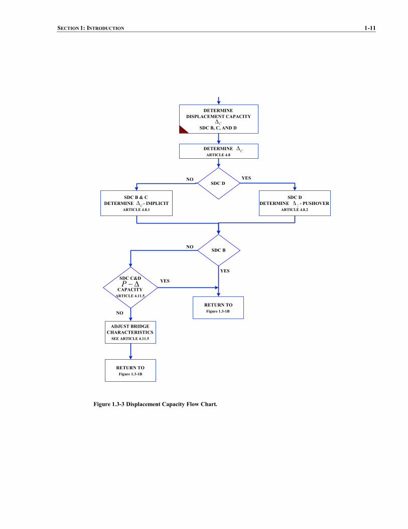
Figure 1b shows the core flow chart of proceduresoutlined for bridges in SDC B, C, and D. Figure 2 outlinesthe demand analysis. Figure 3 directs the designer todetermine displacement capacity. Figure 4 shows themodeling procedure. Figures 5a & 5b establish memberdetailing requirements based on the type of the structurechosen for seismic resistance. Figure 6 shows thefoundation design.

1-8 AASHTO GUIDE SPECIFICATIONS FOR LRFDSEISMIC BRIDGE DESIGN
PRELIMINARY DESIGN BRIDGETYPE SELECTION AND DESIGN
FOR SERVICE LOADS
APPLICABILITY OFSPECIFICATIONS
ARTICLE 3.1
TEMPORARYBRIDGE
ARTICLE 3.6YES
PERFORMANCE CRITERIAARTICLE 3.2
EARTHQUAKE RESISTING SYSTEMS (ERS)REQUIREMENTS FOR SDC C & D
ARTICLE 3.3
DETERMINE DESIGN RESPONSE SPECTRUMARTICLE 3.4
DETERMINE SEISMIC DESIGN CATEGORY (SDC)ARTICLE 3.5
NO
SDC AYES
NODETERMINE DESIGN FORCESARTICLE 4.6
DETERMINE MINIMUMSUPPORT LENGTH
ARTICLE 4..12
FOUNDATION DESIGNFigure 1.3-6
DESIGN COMPLETE
SINGLE SPANBRIDGE
SEISMIC DESIGN CATEGORY B, C, DSee Figure 1.3-1B
NO
YES
DETERMINE DESIGN FORCESARTICLE 4.5
DETERMINE MINIMUMSUPPORT LENGTH
ARTICLE 4.12
DESIGN COMPLETE
FOUNDATION INVESTIGATIONARTICLE 6.2
Figure 1.3-1a Seismic Design Procedure Flow Chart.

SECTION 1: INTRODUCTION 1-9
SDC B
DISPLACEMENTDEMAND ANALYSIS
Figure 1.3-2
C D� � �
SDC B DETAILINGFigure 1.3-5
COMPLETE
SDC C
SDC C DETAILINGFigure 1.3-5
COMPLETE
CAPACITY DESIGN
SDC D
SDC D DETAILINGFigure 1.3-5
COMPLETE
CAPACITY DESIGN
Yes Yes Yes
Yes Yes Yes
NoNo No
No No
ADJUST BRIDGECHARACTERISTICS
DEPENDSONADJUSTMENTS
(Continued From Figure 1.3-1A)
D�
DISPLACEMENTDEMAND ANALYSIS
Figure 1.3-2D�
DISPLACEMENTDEMAND ANALYSIS
Figure 1.3-2D�
DISPLACEMENTCAPACITY
Figure 1.3-3C�
DISPLACEMENTCAPACITY
Figure 1.3-3C�
DISPLACEMENTCAPACITY
Figure 1.3-3C�
C D� � � C D� � �
SATISFY SUPPORTREQUIREMENTSSUPPORT LENGTH
ARTICLE 4.12
SHEAR KEYARTICLE 4.14
SATISFY SUPPORTREQUIREMENTSSUPPORT LENGTH
ARTICLE 4.12
SHEAR KEYARTICLE 4.14
SATISFY SUPPORTREQUIREMENTSSUPPORT LENGTH
ARTICLE 4.12
SHEAR KEYARTICLE 4.14
FOUNDATION DESIGNFigure 1.3-6
FOUNDATION DESIGNFigure 1.3-6
FOUNDATION DESIGNFigure 1.3-6
Article4.8.1
Article4.8.1
Figure 1.3-1b Seismic Design Procedure Flow Chart.

1-10 AASHTO GUIDE SPECIFICATIONS FOR LRFDSEISMIC BRIDGE DESIGN
DISPLACEMENTDEMAND ANALYSIS
SDC B, C, D
SEISMIC DESIGN PROPORTIONINGRECOMMENDATIONS
ARTICLE 4.1
SDC D
CONSIDER VERTICALGROUND MOTION EFFECTS
ARTICLE 4.7.2
YES
SELECT HORIZONTAL AXESFOR GROUND MOTIONS
ARTICLE 4.3.1
DAMPING CONSIDERATIONARTICLE 4.3.2
SHORT PERIOD STRUCTURESCONSIDERATION
ARTICLE 4.3.3
ANALYTICAL MODELING AND PROCEDURES(See Figure1.3-4)
RETURN TOFigure 1.3-1B
NO
DETERMINE ANALYSIS PROCEDUREARTICLE 4.2
D�
Figure 1.3-2 Demand Analysis Flow Chart.
SECTION 1: INTRODUCTION 1-11
SDC DDETERMINE - PUSHOVER
ARTICLE 4.8.2
NO
YES
C�
C�
YES
SDC DNO
DETERMINEARTICLE 4.8
SDC B & CDETERMINE - IMPLICIT
ARTICLE 4.8.1C�
SDC B
SDC C&D
CAPACITYARTICLE 4.11.5
��P YES
ADJUST BRIDGECHARACTERISTICSSEE ARTICLE 4.11.5
NO
DETERMINEDISPLACEMENT CAPACITY
SDC B, C, AND DC�
RETURN TOFigure 1.3-1B
RETURN TOFigure 1.3-1B
Figure 1.3-3 Displacement Capacity Flow Chart.

1-12 AASHTO GUIDE SPECIFICATIONS FOR LRFDSEISMIC BRIDGE DESIGN
COMBINE ORTHOGONAL DISPLACEMENTS(i.e., LOADS CASES 1 & 2)
ARTICLE 4.4
DETERMINE SEISMIC DISPLACEMENTDEMANDS FOR SDC B, C, D
SECTION 5
SELECT ANALYTICALPROCEDURES
ARTICLE 5.4
PROCEDURE 1: ESAARTICLE 5.4.2
PROCEDURE 2: EDAARTICLE 5.4.3
PROCEDURE 3: NONLINEAR TIMEHISTORYARTICLE 5.4.4
DEFINE BRIDGE ERSARTICLE 5.1.1ARTICLE 3.3
NO
YES
EFFECTIVE SECTION PROPERTIESARTICLE 5.6
SATISFY MATHEMATICAL MODELINGREQUIREMENTS FOR PROCEDURE 2
ARTICLE 5.5
ABUTMENT MODELINGARTICLE 5.2
FOUNDATION MODELINGARTICLE 5.3
SDC C or D
CONDUCT DEMAND ANALYSISARTICLE 5.1.2
RETURN TOSee Figure 1.3-2
DETERMINE DISPLACEMENTDEMANDS ALONG
MEMBER LOCAL AXISARTICLE 4.8
Figure 1.3-4 Modeling Procedure Flow Chart.

SECTION 1: INTRODUCTION 1-13
TYPE 1� DUCTILE SUBSTRUCTURE� ESSENTIALLY ELASTICSUPERSTRUCTURE
TYPE 1
SATISFY MEMBER DUCTILITYREQUIREMENTS FOR SDC D
ARTICLE 4.9
DETERMINE FLEXURE ANDSHEAR DEMANDS
ARTICLE 8.3
SATISFY REQUIREMENTS FORCAPACITY PROTECTED MEMBERS
FOR SDC C AND DARTICLE 8.9
SATISFY REQUIREMENTS FORDUCTILE MEMBERS DESIGN
FOR SDC C AND DARTICLE 8.7
SATISFY LATERAL ANDLONGITUDINAL REINFORCEMENT
REQUIREMENTSARTICLES 8.6 & 8.8
SUPERSTRUCTURE DESIGN FORLONGITUDINAL DIRECTION
FOR SDC C AND DARTICLE 8.10
SUPERSTRUCTURE DESIGN FORTRANSVERSE DIRECTIONINTEGRAL BENT CAPSFOR SDC C AND D
ARTICLE 8.11
NON-INTEGRAL BENT CAPFOR SDC C AND D
ARTICLE 8.12
SUPERSTRUCTURE JOINT DESIGNFOR SDC C AND D
ARTICLE 8.13
COLUMN FLARES FOR SDC C AND DARTICLE 8.14
COLUMN SHEAR KEY DESIGNFOR SDC C AND D
ARTICLE 8.15
RETURN TO
Figure 1.3-1B
TYPE 1*DUCTILE MOMENT RESISTING
FRAMES AND SINGLE COLUMNSTRUCTURES FOR SDC C AND D
ARTICLE 7.5
COLUMN REQUIREMNTSFOR SDC C AND D
ARTICLE 7.5.1
BEAM REQUIREMNTSFOR SDC C AND D
ARTICLE 7.5.2
PANEL ZONES AND CONNECTIONSFOR SDC C AND D
ARTICLE 7.5.3
TYPE 1**CONCRETE FILLED STEEL PIPES
FOR SDC C AND DARTICLE 7.6
COMBINED AXIAL COMPRESSIONAND FLEXUREARTICLE 7.6.1
FLEXURAL STRENGTHARTICLE 7.6.2
BEAMS AND CONNECTIONSARTICLE 7.6.3
Note:
1) Type 1 considers concrete substructure2) Type 1* considers steel substructure
3) Type 1** considers concrete filled steel pipessubstructure
Figure 1.3-5a Detailing Procedure Flow Chart.

1-14 AASHTO GUIDE SPECIFICATIONS FOR LRFDSEISMIC BRIDGE DESIGN
TYPE 2 & 3
ISOLATION DEVICESARTICLE 7.8
FIXED AND EXPANSION BEARINGSARTICLE 7.9
RETURN TOFigure 1.3-1B
USE REDUCTION FACTORSARTICLE 7.2
SATISFY MEMBER REQUIREMENTSFOR SDC C AND D
ARTICLE 7.4
SATISFY CONNECTIONREQUIREMENTS FOR SDC C AND D
ARTICLE 7.7
SATISFY BEARING REQUIREMENTSARTICLE 7.9
Note: Type 2 and Type 3 considers concrete orsteel substructure
TYPE 2 TYPE 3
ESSENTIALLY ELASTICSUBSTRUCTURE
WITHDUCTILE STEELSUPERSTRUCTURE
ESSENTIALLY ELASTICSUPERSTRUCTURE
ANDELASTIC SUBSTRUCTURE
WITHFUSINGMECHANISM AT INTERFACEBETWEEN SUPERSTRUCTURE AND
SUBSTRUCTURE
ARTICLE 7.2
Figure 1.3-5b Detailing Procedure Flow Chart.

SECTION 1: INTRODUCTION 1-15
CONCRETE PILES FOR SDC C&DARTICLE 8.16
ABUTMENT DESIGNARTICLE 6.7
RETURN TOFigure 1.3-1B
SPREAD FOOTING DESIGNARTICLE 6.3
PILE CAP FOUNDATION DESIGNARTICLE 6.4
DRILLED SHAFTARTICLE 6.5
FOUNDATION DESIGN
Figure 1.3-6 Foundation Design Flow Chart.

SECTION 2: DEFINITIONS AND NOTATION
TABLE OF CONTENTS
2-i
2.1 DEFINITIONS.......................................................................................................................................................... 12.2 NOTATION.............................................................................................................................................................. 3
TO BE UPDATED BY AASHTO PUBLICATIONS


SECTION 2
DEFINITIONS ANDNOTATION
2-1
2.1 DEFINITIONS
Capacity Design – A method of component design that allows the designer to prevent damage in certain componentsby making them strong enough to resist loads that are generated when adjacent components reach their overstrengthcapacity.
Capacity Protected Element – Part of the structure that is either connected to a critical element or within its load pathand that is prevented from yielding by virtue of having the critical member limit the maximum force that can betransmitted to the capacity protected element.
Collateral Seismic Hazard – Seismic hazards other than direct ground shaking such as liquefaction, fault rupture, etc.
Complete Quadratic Combination (CQC) –A statistical rule for combining modal responses from an earthquake loadapplied in a single direction to obtain the maximum response due to this earthquake load.
Critical or Ductile Elements – Parts of the structure that are expected to absorb energy, undergo significant inelasticdeformations while maintaining their strength and stability.
Damage Level –A measure of seismic performance based on the amount of damage expected after one of the designearthquakes.
Displacement Capacity Verification – A design and analysis procedure that requires the designer to verify that his orher structure has sufficient displacement capacity. It generally involves a non-linear static (i.e. “pushover”) analysis.
Ductile Substructure Elements – See Critical or Ductile Elements
Earthquake Resisting Element (ERE) – The individual components, such as columns, connections, bearings, joints,foundation, and abutments, that together constitute the Earthquake Resisting System (ERS).
Earthquake Resisting System (ERS) – A system that provides a reliable and uninterrupted load path for transmittingseismically induced forces into the ground and sufficient means of energy dissipation and/or restraint to reliablycontrol seismically induced displacements.
Life Safety Performance Level – The minimum acceptable level of seismic performance allowed by this specification.It is intended to protect human life during and following a rare earthquake.
Liquefaction – Seismically induced loss of shear strength in loose, cohesionless soil that results from a build up of porewater pressure as the soil tries to consolidate when exposed to seismic vibrations.
Liquefaction-Induced Lateral Flow – Lateral displacement of relatively flat slopes that occurs under the combinationof gravity load and excess pore water pressure (without inertial loading from earthquake). Lateral flow often occursafter the cessation of earthquake loading.
Liquefaction-Induced Lateral Spreading – Incremental displacement of a slope that occurs from the combined effectsof pore water pressure buildup, inertial loads from the earthquake, and gravity loads.
Minimum Support Width – The minimum prescribed width of a bearing seat that is required to be provided in a newbridge designed according to these specifications.Nominal Resistance – Resistance of a member, connection or structure based on the expected yield strength (Fye) orother specified material properties, and the nominal dimensions and details of the final section(s) chosen, calculatedwith all material resistance factors taken as 1.0.
Operational Performance Level – A higher level of seismic performance that may be selected by a bridge owner whowishes to have immediate service and minimal damage following a rare earthquake.

2-2 AASHTO GUIDE SPECIFICATION FOR LRFDSEISMIC BRIDGE DESIGN
Overstrength Capacity – The maximum expected force or moment that can be developed in a yielding structuralelement assuming overstrength material properties and large strains and associated stresses.
Performance Criteria – The levels of performance in terms of post earthquake service and damage that are expected toresult from specified earthquake loadings if bridges are designed according to this specification.
Plastic Hinge – The region of a structural component, usually a column or a pier in bridge structures, that undergoesflexural yielding and plastic rotation while still retaining sufficient flexural strength.
Pushover Analysis – See Displacement Capacity Verification
Plastic Hinge Zone – Those regions of structural components that are subject to potential plastification and thus shallbe detailed accordingly.
Response Modification Factor (R-Factor) – Factors used to modify the element demands from an elastic analysis toaccount for ductile behavior and obtain design demands.
Seismic Design Category (SDC) – one of four Seismic Design Categories (SDC), A through D, based on the onesecond period design spectral acceleration for the Life Safety Design Earthquake
Service Level – A measure of seismic performance based on the expected level of service that the bridge is capable ofproviding after one of the design earthquakes.
Site Class – One of six classifications used to characterize the effect of the soil conditions at a site on ground motion.
Tributary Weight – The portion of the weight of the superstructure that would act on a pier participating in the ERS ifthe superstructure between participating piers consisted of simply supported spans. A portion of the weight of the pieritself may also be included in the tributary weight.

SECTION2: DEFINITIONS AND NOTATION 2-3
2.2 NOTATION
The following symbols and definitions apply to these Guide Specifications:
A = cross sectional area of member (in.2) (7.5.2)Ac = area of the concrete core (in.2) (C7.6) (7.6.1) (7.6.2)botcapA = area of bent cap bottom flexural steel (in.2) (8.13.4.2.3)topcapA = area of bent cap top flexural steel (in.2) (8.13.4.2.3)
Ae = effective area of the cross section for shear resistance (in.2) (8.6.2) (8.6.4) (8.6.9)Aew = cross sectional area of pier wall (in.2) (5.6.2)Ag = gross area of section along the plane resisting tension (in.2); gross area ofmember cross section (in.2) (7.7.6)
(8.6.2) (8.7.2) (8.8.1) (8.8.2)Agg = gross area of gusset plate (in.2) (7.7.9)Ajh = effective horizontal joint area (in.) (8.13.2)
ftgjhA = effective horizontal area at mid-depth of the footing assuming a 45o spread away from the boundary of the
column in all directions as shown in Figure 6.4.5-1 (in.2) (6.4.5)Ajv = effective vertical joint area (in.) (8.13.2)Al = area of longitudinal reinforcement in member (in.2) (8.8.1) (8.8.2)An = net area of section along the plane resisting tension (in.2) (7.7.6)As = area of the steel pipe (in.2); effective peak ground acceleration coefficient (3.4.1) (4.5) (4.12.1) (5.2.4.1)
(6.7.1) (C7.6)barj
sA� = area of vertical j-dowels hooked around the longitudinal top deck steel required atmoment resisting joints for
integral cap of bent with a skew angle >20º (in.2) (8.13.4.2.4)jhsA = cross sectional area of horizontal stirrups required at moment resisting joints (in.2) (8.13.4.2.2)jlsA = cross sectional area of required additional longitudinal cap beam reinforcement (in.2) (8.13.5.1.3)jvsA = cross sectional area of vertical stirrups required at moment resisting joints (in.2) (8.13.4.2.1)jvisA = cross sectional area of vertical stirrup required inside the joint region (in.2) (8.13.5.1.2)jvosA = cross sectional area of vertical stirrup required outside the joint region (in.2) (8.13.5.1.1)sfsA = total longitudinal (horizontal) side face reinforcement in the bent cap required at moment resisting joints
(in.2) (8.13.4.2.3)Asp = area of spiral or hoop reinforcement (in.2) (8.6.2) (8.6.3)Ast = total area of column reinforcement anchored in the joint (in.2) (8.13.3) (8.13.4.2.1) (8.13.4.2.2) (8.13.4.2.4)
(8.13.5.1.1) (8.13.5.1.2) (8.13.5.1.3)Atg = gross area of section along the plane resisting tension in block shear failure mode (in.2) (7.7.6)Atn = net area of section along the plane resisting tension in block shear failure mode (in.2) (7.7.6)Av = cross sectional area of shear reinforcement in the direction of loading (in.2) (8.6.2) (8.6.3) (8.6.9)Avg = gross area of section along the plane resisting shear in block shear failure mode (in.2) (7.7.6)Avn = net area of section along the plane resisting shear in block shear failure mode (in.2) (7.7.6)B = width of footing measured normal to the direction of loading (ft.) (6.3.4) (6.3.6)Bc = diameter or width of column or wall measured normal to the direction of loading (in.) (6.3.6) (6.4.5)Bcap = thickness of the bent cap (in.) (8.11) (8.13.2)Beff = effective width of the superstructure or bent cap for resisting longitudinal seismic moment (in.) (8.10) (8.11)
ftgeffB = effective width of footing (in.) (6.4.5)Bo = column diameter or width measured parallel to the direction of displacement under consideration (ft.) (4.8.1)b = width of unstiffened or stiffened element (in.); width of columnor wall in direction of bending (in.) (7.4.2)
(8.6.2) (8.6.9)beff = effective width of the footing used to calculate the nominal moment capacity of the footing (ft.) (6.3.6)b/t = width-thickness ratio of unstiffened or stiffened element (7.4.2)
pileiC )( = compression force in “ith” pile (kip) (6.4.2)
cx(i) = distance from neutral axis of pile group to “ith” row of piles measured parallel to the “x” axis (ft.) (6.4.2)cy(i) = distance from neutral axis of pile group to “ith” row of piles measured parallel to the “y” axis (ft.) (6.4.2)

2-4 AASHTO GUIDE SPECIFICATION FOR LRFDSEISMIC BRIDGE DESIGN
D = distance from active fault (miles); diameter of HSS tube (in.); outside diameter of steel pipe (in.); diameter ofcolumn or pile (in.) (3.4.3) (3.4.4) (7.4.2) (7.6.2) (8.16.1)
D’ = diameter of spiral or hoop (in.) (8.6.2) (8.6.3)D/C = displacement demand to capacity ratio (3.5)D/t = diameter to thickness ratio of a steel pipe (7.4.2) (C7.6.1)D* = diameter of circular shafts or cross section dimension in direction under consideration for oblong shafts (in.)
(4.11.6)Dc = diameter or depth of column in direction of loading (ft. or in.) (6.3.2) (C6.3.6) (8.8.6) (8.10) (8.13.2)
(8.13.4.2.4) (8.13.5)Dcj = column width or diameter parallel to the direction of bending (in.) (6.4.5)Dc,max = larger cross section dimension of the column (in.) (8.8.10) (8.8.13)Dftg = depth of the pile cap or footing (ft. or in.) (6.4.2) (6.4.5)Dg = width of gap between backwall and superstructure (ft.) (5.2.3.3)Ds = depth of superstructure at the bent cap (in.) (8.7.1) (8.10) (8.13.2)d = depth of superstructure or cap beam (in.); overall depth of section (in.); depth of section in direction of
loading (in.) (4.11.2) (8.13.5) (7.4.2) (8.6.3) (8.6.9)dbl = nominal diameter of longitudinal column reinforcing steel bars (in.) (4.11.6) (8.8.4) (8.8.6)di = thickness of “ith” soil layer (ft.) (3.4.2.2)E = modulus of elasticity of steel (ksi) (7.4.2) (7.7.5)Ec = modulus of elasticity of concrete (ksi) (5.6.2) (C7.6)EcIeff = effective flexural stiffness (kip-in2) (5.6.1) (5.6.2)Es = modulus of elasticity of steel (ksi) (C7.6) (8.4.2)Fa = site coefficient for 0.2 second period spectral acceleration (3.4.1) (3.4.2.3)Fpga = site coefficient for the peak ground acceleration coefficient (3.4.1) (3.4.2.3)Fu = minimum tensile strength of steel (ksi) (7.7.6)Fv = site coefficient for 1.0 second period spectral acceleration (3.4.1) (3.4.2.3)Fw = factor taken as between 0.01 to 0.05 for soils ranging from dense sand to compacted clays (5.2.3.3)Fy = specified minimum yield strength of steel (ksi); nominal yield stress of steel pipe or steel gusset plate (ksi)
(7.3) (7.4.1) (7.4.2) (7.7.6) (7.6.2) (7.7.5) (7.7.8) (7.7.9)Fye = expected yield stress of structural steel member (ksi) (7.3) (7.5.2)cf � = nominal uniaxial compressive concrete strength (ksi) (6.4.5) (7.6.1) (7.6.2) (8.4.4) (8.6.2) (8.6.4) (8.6.9)
(8.7.2) (8.8.4) (8.8.6) (C8.13.2) (8.13.3)ccf � = confined compressive strength of concrete (ksi) (8.4.4)
cef � = expected concrete compressive strength (ksi) (8.4.4) (C8.13.2)fh = average normal stress in the horizontal direction within a moment resisting joint (ksi) (8.13.2)fps = stress in prestressing steel corresponding to strain �ps (ksi) (8.4.3)fue = expected tensile strength (ksi) (8.4.2)fv = average normal stress in the vertical direction within a moment resisting joint (ksi) (6.4.5) (8.13.2)fy = specified minimum yield stress (ksi) (8.4.2)fye = expected yield strength (ksi) (4.11.6) (8.4.2) (8.8.4) (8.8.6) (8.11)fyh = yield stress of spiral, hoop or tie reinforcement (ksi) (8.6.2) (8.6.3) (8.6.9) (8.8.8) (8.13.3)G = soil dynamic (secant) shear modulus (ksi) (5.3.2)(GA)eff = effective shear stiffness parameter of the pier wall (kip) (5.6.1) (5.6.2)Gc = shear modulus of concrete (ksi) (5.6.2)GcJeff = torsional stiffness (5.6.1)Gf = gap between the isolated flare and the soffit of the bent cap (in.) (4.11.6)Gmax = soil low-strain (initial) shear modulus (5.3.2)g = acceleration due to gravity (ft./sec.2 or in./sec.2) (C5.4.2)H = thickness of soil layer (ft.); column height used to calculate minimum support length (in.) (3.4.2.1) (4.12.1)Hf = depth of footing (ft.) (6.3.2) (6.3.4) (6.3.6)Hh = the height from the top of the footing to the top of the column or the equivalent column height for a pile
extension column (ft.) (8.7.1)Ho = clear height of column (ft.) (4.8.1)Hw = height of backwall or diaphragm (ft.) (5.2.3.3)H � = length of pile shaft/column from point of maximum moment to point of contraflexure above ground (in.)
(4.11.6)

SECTION2: DEFINITIONS AND NOTATION 2-5
h = web depth (in.); distance from c.g. of tensile force to c.g. of compressive force on the section (in.) (7.4.2)(8.13.2)
h/tw = web depth-thickness ratio (7.4.2)Ic = moment of inertia of the concrete core (in.4) (C7.6)Ieff = effective moment of inertia of the section based upon cracked concrete and first yield of the reinforcing steel
(in.4); effective moment of inertia of the section based upon cracked concrete and first yield of the reinforcingsteel or effective moment of inertia taken about the weak axis of the reinforced concrete cross section (in.4)(5.6.1) (5.6.2) (5.6.3) (5.6.4)
Ig = gross moment of inertia taken about the weak axis of the reinforced concrete cross section (in.4) (5.6.2)(5.6.3) (5.6.4)
Ipg(x) = effective moment of inertia of pile group about the “x” axis (pile-ft.2) (6.4.2)Ipg(y) = effective moment of inertia of pile group about the “y” axis (pile-ft.2) (6.4.2)Is = moment of inertia of a single longitudinal stiffener about an axis parallel to the flange and taken at the base of
the stiffener (in.4); moment of inertia of the steel pipe (in.4) (7.4.2) (C7.6)Jeff = effective torsional (polar) moment of inertia of reinforced concrete section (in.4) (5.6.1) (5.6.5)Jg = gross torsional (polar) moment of inertia of reinforced concrete section (in.4) (5.6.5)K = effective lateral bridge stiffness (kip/ft. or kip/in.); effective length factor of a member (C5.4.2) (7.4.1)KDED = stiffness of the ductile end diaphragm (kip/in.) (7.4.6)Keff = abutment equivalent linear secant stiffness (kip/ft.) (5.2.3.3)Ki = initial abutment backwall stiffness (kip/ft.) (5.2.3.3)KL/r = slenderness ratio (7.4.1)KSUB = stiffness of the substructure (kip/in.) (7.4.6)k = total number of cohesive soil layers in the upper 100 ft. of the site profile below the bridge foundation; plate
buckling coefficient for uniform normal stress (3.4.2.2) (7.4.2)eik = smaller effective bent or column stiffness (kip/in.) (4.1.1)ejk = larger effective bent or column stiffness (kip/in.) (4.1.1)
L = length of column frompoint of maximummoment to the point of moment contra-flexure (in.); length of thebridge deck to the adjacent expansion joint, or to the end of the bridge deck; for hinges within a span, L shallbe the sum of the distances to either side of the hinge; for single-span bridges, L equals the length of thebridge deck (ft.); total length of bridge (ft. or in.); length of footing measured in the direction of loading (ft.);unsupported length of a member (in.) (4.11.6) (8.8.6) (4.12.1) (C5.4.2) (6.3.2) (6.3.4) (C6.3.6) (7.4.1)
Lc = column clear height used to determine shear demand (in.) (4.11.2)Lftg = cantilever overhang length measured from the face of wall or column to the outside edge of the pile cap or
footing (ft.) (6.4.2)Lg = unsupported edge length of the gusset plate (in.) (7.7.5)Lp = equivalent analytical plastic hinge length (in) (4.11.6) (4.11.7)Lpr = plastic hinge region which defines the portion of the column, pier or shaft that requires enhanced lateral
confinement (in.) (4.11.7)Lu = unsupported length (in.) (C7.4.1)lac = length of column reinforcement embedded into the bent cap or footing (in.) (8.8.4) (8.13.2) (8.13.3)Mg = moment acting on the gusset plate (kip-in.) (7.7.10)Mn = nominal moment capacity (kip-in. or kip-ft.) (4.11.2) (4.11.5) (6.3.6)Mne = nominal moment capacity of a reinforced concrete member based on expected materials properties and a
concrete strain �c = 0.003 (kip-ft.) (8.5) (8.7.1) (8.9)Mng = nominal moment strength of a gusset plate (kip-in.) (7.7.8)Mns = nominal flexural moment strength of a member (kip-in.) (7.4.1)Mnx = probable flexural resistance of column (kip-ft.) (7.5.2)Mp = idealized plastic moment capacity of reinforced concrete member based upon expected material properties
(kip-in. or kip-ft.) (4.11.2) (4.11.5) (8.5)colxpM )( = the component of the column overstrength plastic hingingmoment capacity about the “x” axis (kip-ft.) (6.4.2)
colypM )( = the component of the column overstrength plastic hingingmoment capacity about the “y” axis (kip-ft.) (6.4.2)
Mpo = overstrength plastic moment capacity of the column (kip-in. or kip-ft.) (4.11.2) (6.3.4) (8.5) (8.9) (8.10)(8.13.1) (8.13.2) (8.15)
Mpg = nominal plastic moment strength of a gusset plate (kip-in.) (7.7.8)Mpx = plastic moment capacity of the member based upon expected material properties (kip-ft.) (7.5.2)

2-6 AASHTO GUIDE SPECIFICATION FOR LRFDSEISMIC BRIDGE DESIGN
Mrc = factored nominal moment capacity of member (kip-ft.) (7.6.1)Mrg = factored nominal yield moment capacity of the gusset plate (kip-in.) (7.7.10)Mrpg = factored nominal plastic moment capacity of the gusset plate (kip-in.) (7.7.10)Mu = factored ultimate moment demand (kip-ft. or kip-in.); factored moment demand acting on the member
including the elastic seismic demand divided by the appropriate force reduction factor, R (kip-ft.) (6.3.6)(7.4.1) (7.6.1)
My = moment capacity of section at first yield of the reinforcing steel (kip-in.) (5.6.2)m = total number of cohesionless soil layers in the upper 100 ft. of the site profile below the bridge foundation
(3.4.2.2)mi = tributary mass of column or bent i (kip) (4.1.1)mj = tributary mass of column or bent j (kip) (4.1.1)N = minimum support length measured normal to the centerline of bearing (in.) (4.12) (4.12.1) (4.12.2)N = average standard penetration resistance for the top 100 ft. (blows/ft.) (3.4.2)chN = average standard penetration resistance of cohesionless soil layers for the top 100 ft. (blows/ft.) (3.4.2)
Ni = standard penetration resistance as measured directly in the filed, uncorrected blow count, of “ith” soil layernot to exceed 100 (blows/ft.) (3.4.2.2)
Np = total number of piles in the pile group (pile) (6.4.2)n = total number of distinctive soil layers in the upper 100 ft. of the site profile below the bridge foundation;
number of equally spaced longitudinal compression flange stiffeners; modular ratio; number of individualinterlocking spiral or hoop core sections (3.4.2.2) (7.4.2) (C7.6) (8.6.3)
nx = number of piles in a single row parallel to the “x” axis (pile) (6.4.2)ny = number of piles in a single row parallel to the “y” axis (pile) (6.4.2)Pb = beam axial force at the center of the joint including prestressing (kip) (8.13.2)Pbs = tensile strength of a gusset plate based on block-shear (kip) (7.7.6)Pc = column axial force including the effects of overturning (kip) (8.13.2)Pcol = column axial force including the effects of overturning (kip) (6.4.5)Pdl = unfactored dead load acting on column (kip) (4.11.5)Pg = axial force acting on the gusset plate (kip) (7.7.10)PGA = peak horizontal ground acceleration coefficient on Class B rock (3.4.1) (4.5) (4.12.1) (5.2.4.1) (6.7.1)PI = plasticity index of soil (3.4.2.1)Pn = nominal axial strength of a member (kip) (7.4.1)Png = nominal compression strength of the gusset plates (kip) (7.7.7)Pp = abutment passive lateral earth capacity (kip) (5.2.3.3)Pr = factored nominal axial capacity of member (kip) (7.6.1)Prg = factored nominal yield axial capacity of the gusset plate (kip) (7.7.10)Pro = factored nominal axial capacity of member (kip) (7.6.1)Ptrib = greater of the dead load per column or force associated with the tributary seismic mass collected at the bent
(kip) (8.7.1)Pu = axial force in column including the axial force associated with overstrength plastic hinging (kip); factored
axial compressive load acting on the member (kip); factored axial load acting on the member (kip); ultimatecompressive force acting on section (kip); ultimate compressive force acting on the section including seismicinduced vertical demands (kip) (6.3.4) (C6.3.6) (7.4.1) (7.4.2) (7.5.2) (8.6.2) (8.7.2)
Py = nominal axial yield strength of a member (kip) (7.4.2)pc = principal compressive stress (ksi) (6.4.5) (8.13.2)pe = equivalent uniform static lateral seismic load per unit length of bridge applied to represent the primarymode
of vibration (kip/ft.) (C5.4.2)pp = passive lateral earth pressure behind backwall (ksf) (5.2.3.3)po = uniform lateral load applied over the length of the structure (kip/ft. or kip/in.) (C5.4.2)pt = principal tensile stress (ksi) (6.4.5) (8.13.2)qn = nominal bearing capacity of supporting soil or rock (ksf) (6.3.4)R = maximum expected displacement ductility of the structure; response modification factor (4.3.3) (7.2) (7.2.2)
(7.4.6)RD = damping reduction factor to account for increased damping (4.3.2)Rd = magnification factor to account for short period structure (4.3.3)Rn = nominal resistance against sliding failure (6.3.5)r = radius of gyration (in.) (7.4.1)ry = radius of gyration about minor axis (in.) (7.4.1)

SECTION2: DEFINITIONS AND NOTATION 2-7
S = angle of skew of support measured from a line normal to span (°) (4.12.1) (4.12.2)Sa = design response spectral acceleration coefficient (3.4.1) (C5.4.2)S1 = 1.0 second period spectral acceleration coefficient on Class B rock (3.4.1)SD1 = design earthquake response spectral acceleration coefficient at 1.0 second period (3.4.1) (3.5)SDS = design earthquake response spectral acceleration coefficient at 0.2 second period (3.4.1)Ss = 0.2 second period spectral acceleration coefficient on Class B rock (3.4.1)Sg = elastic section modulus of gusset plate about the strong axis (in.3) (7.7.8)s = spacing of spiral, hoop or tie reinforcement (in.) (8.6.2) (8.6.3) (8.6.9)us = average undrained shear strength in the top 100 ft. (psf) (3.4.2)sui = undrained shear strength of “ith” soil layer not to exceed 5 (ksf) (3.4.2.2)T = period of vibration (sec.); fundamental period of the structure (sec.) (3.4.1) (4.3.3)Tc = column tensile force associated with the column overstrength plastic hinging moment, Mpo (kip) (6.4.5)
(8.13.2)TF = bridge fundamental period (sec.) (3.4.3)Ti = natural period of the less flexible frame (sec.) (4.1.2)pileiT )( = tension force in “ith” pile (kip) (6.4.2)
Tj = natural period of the more flexible frame (sec.) (4.1.2)Tjv = net tension force in moment resisting footing joints (kip) (6.4.5)Tm = period of the mth mode of vibration (sec.) (C5.4.2)To = period at beginning of constant design spectral acceleration plateau (sec.) (3.4.1)Ts = period at the end of constant design spectral acceleration plateau (sec.) (3.4.1) (4.3.3)T* = characteristic ground motion period (sec.) (4.3.3)t = thickness of unstiffened or stiffened element (in.); pipe wall thickness (in.); thickness of gusset plate (in.);
thickness of the top or bottom slab (in.) (7.4.2) (7.6.2) (7.7.5) (8.11)tw = thickness of web plate (in.) (7.4.2)Vc = nominal shear resistance of the concrete (kip) (8.6.1) (8.6.2)Vg = shear force acting on the gusset plate (kip) (7.7.10)Vn = nominal interface shear capacity of shear key as defined in Article 5.8.4 of the AASHTO LRFD Bridge
Design Specifications using the expected material properties and interface surface conditions (kip); nominalshear capacity (kip) (4.14) (6.3.7) (8.6.1) (8.6.9)
Vng = nominal shear strength of a gusset plate (kip) (7.7.9)Vok = overstrength capacity of shear key (4.14) (8.12)Vpo = overstrength shear associated with the overstrength moment Mpo (kip) (4.11.2) (6.3.4) (6.3.5) (8.6.1)Vrg = factored nominal yield shear capacity of the gusset plate (kip) (7.7.10)Vs = nominal shear resistance of the steel (kip) (8.6.1) (8.6.3) (8.6.4)Vu = factored ultimate shear demand in footing at the face of the column or wall (kip); shear demand of a column
or wall (kip) (6.3.7) (8.6.1) (8.6.9)vc = concrete shear stress capacity (ksi) (8.6.2)vjv = nominal vertical shear stress in a moment resisting joint (ksi) (6.4.5) (8.13.2)sv = average shear wave velocity in the top 100 ft. (ft./sec.) (3.4.2)vsi = shear wave velocity of “ith” soil layer (ft./sec.) (3.4.2.2)Vs,max = maximum lateral displacement due to uniform loading po (ft. or in.) (C5.4.2)W = total weight of bridge (kip) (C5.4.2)Ww = width of backwall (ft.) (5.2.3.3)w = moisture content (%) (3.4.2.1)w(x) = nominal unfactored dead load of the bridge superstructure and tributary substructure (kip/ft. or kip/in.)
(C5.4.2)Z = plastic section modulus of steel pipe (in.3) (7.6.2)Zg = plastic section modulus of gusset plate about the strong axis (in.3) (7.7.8)� = central angle formed between neutral axis chord line and the center point of the pipe found by the recursive
equation (rad.) (7.6.2)�EQ = load factor for live load (C4.6)�b = displacement demand due to flexibility of essentially elastic components such as bent caps (in.) (4.3)LC� = displacement capacity taken along the local principal axis corresponding to L
D� of the ductile member asdetermined in accordance with Article 4.8.1 for SDC B and C and in accordance with Article 4.8.2 for SDCD (in.) (C3.3) (4.8) (4.8.1)

2-8 AASHTO GUIDE SPECIFICATION FOR LRFDSEISMIC BRIDGE DESIGN
�D = global seismic displacement demand (in.) (4.3.1) (4.11.5)LD� = displacement demand taken along the local principal axis of the ductile member as determined in accordance
with Article 4.4 (in.) (C3.3) (4.8)�eq = seismic displacement demand of the long period frame on one side of the expansion joint (in.) (4.12.2)�F = pile cap displacement (in.) (4.11.5)�f = displacement demand attributed to foundation flexibility; pile cap displacements (in.) (4.3)�pd = displacement demand attributed to inelastic response of ductile members; plastic displacement demand (in.)
(4.3) (4.9)�r = relative lateral offset between the point of contra-flexure and the furthest end of the plastic hinge (in.)
(4.11.5)�S = pile shaft displacement at the point of maximum moment developed in-ground (in.) (4.11.5)�y = idealized yield displacement; displacement demand attributed to elastic response of ductile members (in.)
(C3.3) (4.3)�yi = idealized yield displacement (in.) (C3.3) (4.9)�cc = compressive strain at maximum compressive stress of confined concrete (8.4.4)�co = unconfined concrete compressive strain at the maximum compressive stress (8.4.4)�cu = ultimate compressive strain for confined concrete (8.4.4)�sp = ultimate unconfined compression (spalling) strain (8.4.4)�ps = strain in prestessing steel (in./in.) (8.4.3)�ps,EE = essentially elastic prestress steel strain (8.4.3)�ps,u = ultimate prestress steel strain (8.4.3)Rups ,� = reduced ultimate prestress steel strain (8.4.3)
�sh = tensile strain at the onset of strain hardening (8.4.2)�su = ultimate tensile strain (8.4.2)Rsu� = reduced ultimate tensile strain (8.4.2)
�ye = expected yield strain (8.4.2) � displacement ductility capacity of the end diaphragm (7.4.6)C = ductility capacity (4.7.1)D = maximum local member displacement ductility demand (4.3.3) (4.7.1) (4.9) (8.6.2)�b = slenderness parameter for flexural moment dominant members (7.4.1)�bp = limiting slenderness parameter for flexural moment dominant members (7.4.1)�c = slenderness parameter for axial compressive load dominant members (7.4.1)�cp = limiting slenderness parameter for axial compressive load dominant members (7.4.1)�mo = overstrength factor (4.11.2) (7.3) (8.5.1)�p = limiting width-thickness ratio for ductile components (7.4.2)�r = limiting width-thickness ratio for essentially elastic components (7.4.2) h = horizontal reinforcement ratio in pier wall (8.6.9) (8.6.10) s = volumetric ratio of spiral reinforcement for a circular column (8.6.2) (8.6.5) (8.8.7) (8.13.3) v = vertical reinforcement ratio in pier wall (8.6.10) w = reinforcement ratio in the direction of bending (8.6.2) (8.6.5) (8.8.7)� = resistance factor (3.7) (6.3.4) (6.3.5) (6.3.6) (7.3)�b = 0.9 resistance factor for flexure (7.4.2)�bs = 0.80 resistance factor for block shear failure mechanisms (7.7.6)�c = 0.75 resistance factor for concrete in compression (7.6.1)�f = 1.0 resistance factor for structural steel in flexure (7.6.2)�s = 0.85 resistance factor for shear in reinforce concrete (6.3.7) (8.6.1) (8.6.9)�u = 0.80 resistance factor for fracture on net section; ultimate curvature capacity (7.7.6) (8.5)�y = curvature of section at first yield of the reinforcing steel including the effects of the unfactored axial dead
load(1/in.); 0.95 resistance factor for yield on gross section (5.6.2) (8.5) (7.7.6)�yi = idealized yield curvature (8.5)� = factor for column end restraint condition (4.8.1) (8.7.1)� = damping ratio (maximum of 0.1) (4.3.2)

SECTION2: DEFINITIONS AND NOTATION 2-9
��
n
iid
1= thickness of upper soil layers = 100 ft. (3.4.2.2)
� pileiT )( = summation of the hold down force in the tension piles (kip) (6.4.5)
�P = total unfactored axial load due to dead load, earthquake load, footing weight, soil overburden and all othervertical demands acting on the pile group (kip) (6.4.2)
SECTION 3: GENERAL REQUIREMENTS
TABLE OF CONTENTS
3-i
3.1 APPLICABILITY OF SPECIFICATIONS ...........................................................................................................3-13.2 PERFORMANCE CRITERIA...............................................................................................................................3-23.3 EARTHQUAKE RESISTING SYSTEMS (ERS) REQUIREMENTS FOR SDC C & D.....................................3-23.4 SEISMIC GROUND SHAKING HAZARD........................................................................................................3-11
3.4.1 Design Spectra Based on General Procedure.............................................................................................3-133.4.2 Site Effects on Ground Motions................................................................................................................. 3-43
3.4.2.1 Site Class Definitions.......................................................................................................................3-433.4.2.2 Definitions of Site Class Parameters................................................................................................3-453.4.2.3 Site Coefficients...............................................................................................................................3-47
3.4.3 Response Spectra Based on Site-Specific Procedures ...............................................................................3-483.4.4 Acceleration Time-Histories ......................................................................................................................3-49
3.5 SELECTION OF SEISMIC DESIGN CATEGORY (SDC)................................................................................3-513.6 TEMPORARY AND STAGED CONSTRUCTION ...........................................................................................3-533.7 LOAD AND RESISTANCE FACTORS .............................................................................................................3-54
TO BE UPDATED BY AASHTO PUBLICATIONS


SECTION 3
GENERAL REQUIREMENTS
3-1
Chapter 33.1 APPLICABILITY OF SPECIFICATIONS
These Specifications shall be taken to apply to thedesign and construction of normal bridges to resist theeffects of earthquake motions. For the purpose of theseprovisions, normal bridges should be considered to be newbridges of conventional slab, beam, girder and box girdersuperstructure construction with spans not exceeding 500ft.
Critical/Essential Bridges are not specificallyaddressed in this specification. A bridge should beclassified as Critical/Essential as follows:
� Bridges that are required to be open to all trafficonce inspected after the design earthquake and beusable by emergency vehicles and for security,defense, economical, or secondary life safetypurposes immediately after the designearthquake.
� Bridges that should, as a minimum, be open toemergency vehicles and for security, defense, oreconomical purposes after the design earthquakeand open to all traffic within days after that event.
� Bridges that are formally designated as criticalfor a defined local emergency plan.
For other types of construction (e.g., suspensionbridges, cable-stayed bridges, truss bridges, arch type andmovable bridges) and spans exceeding 500 ft., the Ownershall specify and/or approve appropriate provisions.
Seismic effects for box culverts and buried structuresneed not be considered, except when they are subject tounstable ground conditions (e.g., liquefaction, landslides,and fault displacements) or large ground deformations(e.g., in very soft ground).
The provisions specified in the specifications shouldbe taken as the minimum requirements. Additionalprovisionsmay be specified by the owner to achieve higherperformance criteria for repairable or minimum damageattributed to essential or critical bridges. Where suchadditional requirements are specified, they shall besite/project specific and are tailored to a particularstructure type.
No detailed seismic structural analysis is should berequired for a single span bridge or for any bridge inSeismic Design Category A. Specific detailingrequirements are applied for SDC A. For single spanbridges, minimum support length requirement shall applyaccording to Article 4.12. However, detailed geotechnicalanalysis of the abutments may be required by the owner forsingle span bridges if there is potential for significantlateral spreading or other forms of abutment instability arepossible due to liquefaction.

3-2 AASHTO GUIDE SPECIFICATION FOR LRFDSEISMIC BRIDGE DESIGN
3.2 PERFORMANCE CRITERIA
Bridges shall be designed for the life safetyperformance objective considering a seismic hazardcorresponding to a 7% probability of exceedance in 75years. Higher levels of performance, such as theoperational objective, may be established and authorizedby of the bridge owner. Development of designearthquake ground motions for the 7% probability ofexceedance in 75 years shall be as specified in Article 3.4.
Life safety for the design event shall be taken to implythat the bridge has a low probability of collapse but, maysuffer significant damage and significant disruption toservice is possible. Partial or complete replacement maybe required.
Significant damage shall be taken to includepermanent offsets and damage consisting of:
� cracking,� reinforcement yielding,� major spalling of concrete� extensive yielding and local buckling of steel
columns,� global and local buckling of steel braces, and� cracking in the bridge deck slab at shear studs.
These conditions may require closure to repair thedamages. Partial or complete replacement of columnsmaybe required in some cases. For sites with lateral flow dueto liquefaction, significant inelastic deformation may bepermitted in the piles. Partial or complete replacement ofthe columns and piles may be necessary if significantlateral flow occurs. If replacement of columns or othercomponents is to be avoided, the design strategy producingminimal or moderate damage such as seismic isolation orthe control and reparability design concept should beassessed.
Significant disruption to service shall be taken toinclude limited access (reduced lanes, light emergencytraffic) on the bridge. Shoring may be required.
C3.2
These Guide Specifications are intended to achieveminimal damage to bridges during moderate earthquakeground motions and to prevent collapse during rare, high-amplitude earthquakes. Bridge owners may choose tomandate higher levels of bridge performance for specialbridges.
Allowable displacements are constrained bygeometric, structural and geotechnical considerations. Themost restrictive of these constraints will governdisplacement capacity. These displacement constraintsmay apply to either transient displacements aswould occurduring ground shaking, or permanent displacements asmayoccur due to seismically induced ground failure orpermanent structural deformations or dislocations, or acombination. The extent of allowable displacementsdepends on the desired performance level of the bridgedesign.
Geometric constraints generally relate to the usabilityof the bridge by traffic passing on or under it. Therefore,this constraint will usually apply to permanentdisplacements that occur as a result of the earthquake. Theability to repair such displacements or the desire not to berequired to repair them should be considered whenestablishing displacement capacities. When uninterruptedor immediate service is desired, the permanentdisplacements should be small or non-existent, and shouldbe at levels that are within an accepted tolerance fornormally operational highways of the type beingconsidered. A bridge designed to a performance level ofno collapse could be expected to be unusable afterliquefaction, for example, and geometric constraints wouldhave no influence. However, because life safety is at theheart of the no collapse requirement, jurisdictions mayconsider establishing some geometric displacement limitsfor this performance level for important bridges or thosewith high average daily traffic (ADT). This can be doneby considering the risk to highway users in the momentsduring or immediately following an earthquake. Forexample, an abrupt vertical dislocation of the highway ofsufficient height could present an insurmountable barrierand thus result in a collision that could kill or injure.Usually these types of geometric displacement constraintswill be less restrictive than those resulting from structuralconsiderations and for bridges on liquefiable sites it maynot be economic to prevent significant displacements fromoccurring.
3.3 EARTHQUAKE RESISTING SYSTEMS (ERS)REQUIREMENTS FOR SDCC & D
For SDCC or D (see Article 3.5), all bridges and theirfoundations shall have a clearly identifiable EarthquakeResisting System (ERS) selected to achieve the Life SafetyCriteria defined in Article 3.2. The ERS shall provide areliable and uninterrupted load path for transmitting
C3.3
Selection of an appropriate ERS is fundamental toachieving adequate seismic performance. To this end, theidentification of the lateral-force-resisting concept and theselection of the necessary elements to fulfill the conceptshould be accomplished in the conceptual design phase, or

SECTION 3: GENERAL REQUIREMENTS 3-3
seismically induced forces into the surrounding soil andsufficient means of energy dissipation and/or restraint toreliably control seismically induced displacements. Allstructural and foundation elements of the bridge shall becapable of achieving anticipated displacements consistentwith the requirements of the chosen design strategy ofseismic resistance and other structural requirements.
Design should be based on the three Global SeismicDesign Strategies used in this specification based on theexpected behavior characteristics of the bridge system, andthey include:
� Type 1 – Ductile Substructure with EssentiallyElastic Superstructure – This category includesconventional plastic hinging in columns andwallsand abutments that limit inertial forces by fullmobilization of passive soil resistance. Alsoincluded are foundations that may limit inertialforces by in-ground hinging, such as pile bentsand integral abutments on piles.
� Type 2 – Essentially Elastic Substructure with aDuctile Superstructure – This category appliesonly to steel superstructures and ductility isachieved by ductile elements in the pier crossframes.
� Type 3 – Elastic Superstructure and Substructurewith a Fusing Mechanism Between The Two –This category includes seismically isolatedstructures and structures where supplementalenergy dissipation devices, such as dampers, areused to control inertial forces transferred betweenthe superstructure and substructure.
See also Article 7.2.
For the purposes of encouraging the use of appropriatesystems and of ensuring due consideration of performancefor the owner, the ERS and earthquake resisting elements(ERE) shall be categorized as follows:
� Permissible,
� Permissible with Owner’s Approval, and
� Not Recommended for New Bridges.
These terms shall be taken to apply to both systemsand elements. For a system to be in the permissiblecategory, its primary ERE’s shall be in the permissiblecategory. If any ERE is not permissible, then the entiresystem shall be considered to be not permissible.
the type, size and location phase, or the design alternativephase of a project.
Seismic performance is typically better in systemswith regular configurations and evenly distributed stiffnessand strength. Thus, typical geometric configurationconstraints, such as skew, unequal pier heights, and sharpcurves, may conflict with seismic design goals. For thisreason, it is advisable to resolve potential conflictsbetween configuration and seismic performance early inthe design effort. For example, resolution may lead todecreased skew angles at the expense of longer end spans.The resulting trade-off between performance and costshould be evaluated in the type, size, and location phase, ordesign alternative phase, of a project, when designalternatives are viable from a practical viewpoint.
The classification of ERS and ERE into permissibleand not recommended categories is meant to trigger dueconsideration of seismic performance that leads to themostdesirable outcome, that is, seismic performance thatensures, wherever possible, post-earthquake serviceability.To achieve such an objective, special care in detailing theprimary energy-dissipating elements is necessary.Conventional reinforced concrete constructionwith ductileplastic-hinge zones can continue to be used, but designersshould be aware that such detailing, although providingdesirable seismic performance, will leave the structure in adamaged state following a large earthquake. It may bedifficult or impractical to repair such damage.
Under certain conditions the use of ERE’s that requireowners’ approval will be necessary. In previousAASHTOseismic specifications some of the ERE’s in the owners’approval category were simply not permitted for use (e.g.,in-ground hinging of piles and shafts, and foundationrocking). These elements are now permitted, providedtheir deformation performance is assessed.
This approach of allowing their use with additionalanalytical effort was believed to be preferable to anoutright ban on their use. Thus, it is not the objective ofthis specification to discourage the use of systems thatrequire owner approval. Instead, such systems may beused, but additional design effort and consensus betweenthe designer and owner are required to implement suchsystems.
Common examples from each of the three ERS andERE categories are shown in Figures 1a and 1b,respectively.
Bridges are seismically designed so that inelasticdeformation (damage) intentionally occurs in columns inorder that the damage can be readily inspected andrepaired after an earthquake. Capacity design proceduresare used to prevent damage from occurring in foundationsand beams of bents and in the connections of columns tofoundations and columns to the superstructure. There aretwo exceptions to this design philosophy. For pile bentsand drilled shafts, some limited inelastic deformation ispermitted below the ground level. The amount ofpermissible deformation is restricted to ensure that no

3-4 AASHTO GUIDE SPECIFICATION FOR LRFDSEISMIC BRIDGE DESIGN
long-term serviceability problems occur from the amountof cracking that is permitted in the concrete pile or shaft.The second exception is with lateral spreading associatedwith liquefaction. For the life-safety performance level,significant inelastic deformation is permitted in the piles. Itis a costly and difficult problem to achieve a higherperformance level from piles. There are a number ofdesign approaches that can be used to achieve theperformance objectives. These are discussed briefly below.
Type 1-Ductile Substructure with Essentially ElasticSuperstructure. Caltrans first introduced this designapproach in 1973 following the 1971 San Fernandoearthquake. It was further refined and applied nationally inthe 1983 AASHTOGuide Specification for SeismicDesignof Highway Bridges, which was adopted directly from theATC-6 Report , Seismic Design Guidelines for HighwayBridges (ATC, 1981). These provisions were adopted byAASHTO in 1991 as their standard seismic provisions.
Permissible systems and elements depicted inFigures1a and 1b shall have the following characteristics:
� All significant inelastic action shall be ductile andoccur in locations with adequate access forinspection and repair. Piles subjected to lateralmovement from lateral flow resulting fromliquefaction are permitted to hinge below theground line provided the owner is informed anddoes not require any higher performance criteriafor a specific objective. If all structural elementsof a bridge are designed elastically then noinelastic deformation is anticipated and elasticelements are permissible, but minimum detailingis required according to the bridge SeismicDesign Category (SDC).
� Inelastic action of a structural member does notjeopardize the gravity load support capability ofthe structure (e.g. cap beam and superstructurehinging).
Permissible systems depicted in Figure 2 that do notmeet either criteria above may be used only with approvalby the owner.
In general, systems that do not fall in either of the twopermissible categories depicted in Figure 3 shall beconsidered not recommended. However, if adequateconsideration is given to all potential modes of behaviorand potential undesirable failure mechanisms aresuppressed, then such systems may be used with theowner’s approval.
This approach is based on the expectation ofsignificant inelastic deformation (damage) associatedwithductility equal or greater than 4.
The other key premise of the provisions is thatdisplacements resulting from the inelastic response of abridge are approximately equal to the displacementsobtained from an analysis using the linear elastic responsespectrum. As diagrammatically shown in Figure C1 thisassumes that L
C� is equal to LD� . Work by Miranda and
Bertero (1994) and by Chang and Mander (1994a & b)indicates that this is a reasonable assumption except forshort period structures for which it is non-conservative. Acorrection factor to be applied to elastic displacements toaddress this issue is given in Article 4.3.3.
Type 2 – Essentially Elastic Substructure with aDuctile Superstructure. This category applies only to steelsuperstructures. The ductility is achieved by constructingductile elements as part of the cross fames of a steel slab-on-girder bridge superstructure. The deformation capacityof the cross frames located at each pier permits lateraldisplacement of the deck relative to the substructurebelow. This is an emerging technology and has not beenwidely utilized as a design strategy for new construction.
Type 3 – Elastic Superstructure and Substructure witha Fusing Mechanism Between the Two. This category iscomprised of seismically isolated structures and structureswhere energy dissipation devices are used acrossarticulation joints to provide a mechanism to limit energybuild-up and associated displacements during a largeearthquake. The two sub-categories are discussed furtherbelow.
Seismic Isolation. This design approach reduces theseismic forces a bridge needs to resist by introducing anisolation bearing with an energy dissipation element at thebearing location. The isolation bearing intentionallylengthens the period of a relatively stiff bridge and thisresults in lower design forces provided the design is in thedecreasing portion of the acceleration response spectrum.This design alternative was first applied in the United
SECTION 3: GENERAL REQUIREMENTS 3-5
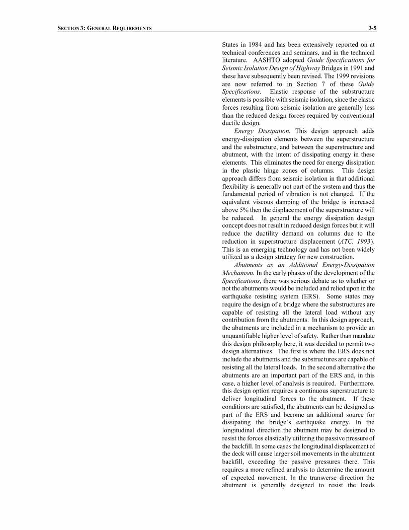
States in 1984 and has been extensively reported on attechnical conferences and seminars, and in the technicalliterature. AASHTO adopted Guide Specifications forSeismic Isolation Design of HighwayBridges in 1991 andthese have subsequently been revised. The 1999 revisionsare now referred to in Section 7 of these GuideSpecifications. Elastic response of the substructureelements is possible with seismic isolation, since the elasticforces resulting from seismic isolation are generally lessthan the reduced design forces required by conventionalductile design.
Energy Dissipation. This design approach addsenergy-dissipation elements between the superstructureand the substructure, and between the superstructure andabutment, with the intent of dissipating energy in theseelements. This eliminates the need for energy dissipationin the plastic hinge zones of columns. This designapproach differs from seismic isolation in that additionalflexibility is generally not part of the system and thus thefundamental period of vibration is not changed. If theequivalent viscous damping of the bridge is increasedabove 5% then the displacement of the superstructure willbe reduced. In general the energy dissipation designconcept does not result in reduced design forces but it willreduce the ductility demand on columns due to thereduction in superstructure displacement (ATC, 1993).This is an emerging technology and has not been widelyutilized as a design strategy for new construction.
Abutments as an Additional Energy-DissipationMechanism. In the early phases of the development of theSpecifications, there was serious debate as to whether ornot the abutments would be included and relied upon in theearthquake resisting system (ERS). Some states mayrequire the design of a bridge where the substructures arecapable of resisting all the lateral load without anycontribution from the abutments. In this design approach,the abutments are included in a mechanism to provide anunquantifiable higher level of safety. Rather than mandatethis design philosophy here, it was decided to permit twodesign alternatives. The first is where the ERS does notinclude the abutments and the substructures are capable ofresisting all the lateral loads. In the second alternative theabutments are an important part of the ERS and, in thiscase, a higher level of analysis is required. Furthermore,this design option requires a continuous superstructure todeliver longitudinal forces to the abutment. If theseconditions are satisfied, the abutments can be designed aspart of the ERS and become an additional source fordissipating the bridge’s earthquake energy. In thelongitudinal direction the abutment may be designed toresist the forces elastically utilizing the passive pressure ofthe backfill. In some cases the longitudinal displacement ofthe deck will cause larger soil movements in the abutmentbackfill, exceeding the passive pressures there. Thisrequires a more refined analysis to determine the amountof expected movement. In the transverse direction theabutment is generally designed to resist the loads

3-6 AASHTO GUIDE SPECIFICATION FOR LRFDSEISMIC BRIDGE DESIGN
elastically. The design objective when abutments arerelied upon to resist either longitudinal or transverse loadsis either to minimize column sizes or reduce the ductilitydemand on the columns, accepting that damage may occurin the abutment.
The performance expectation is that inelasticdeformation will occur in the columns as well as theabutments. If large ductility demands occur in the columnsthen the columns may need to be replaced. If largemovements of the superstructure occur the abutment back-wall may be damaged and there may be some settlement ofthe abutment backfill. Large movements of thesuperstructure can be reduced with use of energydissipators and isolation bearings at the abutments and atthe tops of the columns.
In general, the soil behind an abutment is capable ofresisting substantial seismic forces that may be deliveredthrough a continuous superstructure to the abutment.Furthermore, such soil may also substantially limit theoverall movements that a bridge may experience. This isparticularly so in the longitudinal direction of a straightbridge with little or no skew and with a continuous deck.The controversywith this design concept is the scenario ofwhat may happen if there is significant abutment damageearly in the earthquake ground-motion duration and if thecolumns rely on the abutment to resist some of the load.This would be a problem in a long-duration, high-magnitude (greater than magnitude 7), earthquake. Unlessshock transmission units (STUs) are used, a bridgecomposed of multiple simply supported spans cannoteffectively mobilize the abutments for resistance tolongitudinal force. It is recommended that simplysupported spans not rely on abutments for any seismicresistance.
Because structural redundancy is desirable (Buckle etal., 1987), good design practice dictates the use of thedesign alternative where the intermediate substructures,between the abutments, are designed to resist all seismicloads, if possible. This ensures that in the event abutmentresistance becomes ineffective, the bridge will still be ableto resist the earthquake forces and displacements. In sucha situation, the abutments provide an increased marginagainst collapse.

SECTION 3: GENERAL REQUIREMENTS 3-7
Figure 3.3-1a Permissible Earthquake Resisting Systems (ERS).
� Abutment required to resist the design earthquakeelastically
� Longitudinal passive soil pressure shall be lessthan 0.70 of the value obtained using theprocedure given in Article 5.2.3
� Plastic hinges in inspectable locations orelastic design of columns.
� Abutment resistance not required as part ofERS
� Knock-off backwalls permissible
Longitudinal Response
Transverse Response
Transverse orLongitudinal Response
� Plastic hinges in inspectable locations or elasticdesign of columns
� Abutment not required in ERS, breakaway shearkeys permissible
Longitudinal Response
� Isolation bearings accommodate fulldisplacement
� Abutment not required as part of ERS
� Plastic hinges in inspectable locations or elasticdesign of columns
� Isolation bearings with or without energydissipaters to limit overall displacements
� Multiple simply-supported spans with adequatesupport lengths
� Plastic hinges in inspectable locations or elasticdesign of columns
Transverse or Longitudinal Response
Longitudinal Response
12
3 4
5
6

3-8 AASHTO GUIDE SPECIFICATION FOR LRFDSEISMIC BRIDGE DESIGN
Figure 3.3-1b Permissible Earthquake Resisting Elements (ERE).
Columns with architecturalflares – with or without anisolation gap
See Article 8.14
Pier walls with or without piles.
Spread footings that satisfy theoverturning criteria of Article 6.3.4
Capacity-protected pile caps,including caps with batteredpiles, which behave elastically
Piles with ‘pinned-head’ conditions
Seismic isolation bearings or bearingsdesigned to accommodate expectedseismic displacements with no damage
Plastic hinges below cap beams includingpile bents
Above ground / nearground plastic hinges
Tensile yielding and inelasticcompression buckling ofductile concentrically bracedframes
Plastic hinges at baseof wall piers in weakdirection
Seat abutments whose backwallis designed to fuse
Passive abutment resistance required aspart of ERS
Use 70% of passive soil strength designated in Article 5.2.3
isolation gapoptional
1
2
4
56
7 8
9
10
11
12
13
14
Seat abutments whose backwall is designed toresist the expected impact force in anessentially elastic manner
Columns with momentreducing or pinned hinge details
3

SECTION 3: GENERAL REQUIREMENTS 3-9
Figure C3.3-1 Design Using Strategy Type 1.

3-10 AASHTO GUIDE SPECIFICATION FOR LRFDSEISMIC BRIDGE DESIGN
Figure 3.3-2 Permissible Earthquake Resisting Elements that Require Owner’s Approval.
and 8.5.2
Wall piers on pile foundations that are notstrong enough to force plastic hinging into thewall, and are not designed for the DesignEarthquake elastic forces
Passive abutment resistance required aspart of ERS Passive Strength
Limit movement to adjacent bent displacement capacity
Use rocking criteria according to Appendix A
Foundations permitted to rock
Ensure Limited Ductility Response in Piles according to Article4.7.1
Ensure Limited Ductility Response in Piles according toArticle 4.7.1
Ensure Limited Ductility Response in Piles according to Article4.7.1
Ensure Limited Ductility Response in Pilesaccording to Article 4.7.1
Batter pile systems in which thegeotechnical capacities and/or in-groundhinging define the plastic mechanisms.
Sliding of spread footingabutment allowed to limit forcetransferred
Ductile End-diaphragms in superstructure(Article 7.4.6)
More than the outer line of piles ingroup systems allowed to plunge oruplift under seismic loadings
Plumb piles that are not capacity-protected (e.g.,integral abutment piles or pile-supported seatabutments that are not fused transversely)
In-ground hinging in shafts or piles
12
34
5
6
7
89
Use 100% of strength designated in Article 5.2.3

SECTION 3: GENERAL REQUIREMENTS 3-11
Figure 3.3-3 Earthquake Resisting Elements that are not Recommended for New Bridges.
3.4 SEISMIC GROUND SHAKING HAZARD
The ground shaking hazard prescribed in theseSpecifications is defined in terms of acceleration responsespectra and site coefficients which shall be determined inaccordance with the general procedure of Article 3.4.1 or thesite-specific procedure of Article 3.4.3.
In the general procedure, the spectral response parametersshall be determined using the USGS/AASHTO Seismic HazardMaps produced by the U.S. Geological Survey depictingprobabilistic ground motion and spectral response for 7%probability of exceedance in 75 years.
A site-specific procedure shall be used if any of thefollowing apply:
� Soils at the site require site-specific evaluation (i.e.,Site Class F soils, Article 3.4.2.1); unless adetermination is made that the presence of such soilswould not result in a significantly higher response of thebridge.
� The bridge is considered to be critical or essentialaccording to Article 4.2.2 for which a higher degree ofconfidence of meeting the seismic performanceobjectives of Article 3.2 is desired.
� The site is located within 6 miles of a known activefault and its response could be significantly andadversely influenced by near-fault ground motioncharacteristics.
C3.4
Using either the general procedure or the site-specific procedure, a decision as to whether thedesign motion is defined at the ground surface orsome other depth needs to be made as an initial stepin the design process. Article C3.4.2 provides acommentary on this issue.
Examples of conditions that could lead to adetermination that Site Class F soils would not resultin a significantly higher bridge response are:
� localized extent of Site Class F soils, and� limited depth of these soft soils.
As discussed in Article C3.4.2.2, for shortbridges (with a limited number of spans) having earthapproach fills, ground motions at the abutments willgenerally determine the response of the bridge. IfSite Class F soils are localized to the intermediatepiers and are not present at the abutments, the bridgeengineer and geotechnical engineer might concludethat the response of interior piers would notsignificantly affect bridge response.
Article C3.4.2.2 also describes cases where theeffective depth of input ground motion is determinedto be in stiffer soils at depth, below a soft surficiallayer. If the surficial layer results in a classificationof Site Class F and the underlying soil profileclassifies as Site Class E or stiffer, a determinationmight be made that the surficial soils would notsignificantly increase bridge response.
Bearing systems that do not provide for the expecteddisplacements and/or forces (e.g., rocker bearings)
Battered-pile systems that are notdesigned to fuse geotechnically orstructurally by elements withadequate ductility capacity
Cap beam plastic hinging (particularlyhinging that leads to vertical girdermovement) also includes eccentricbraced frames with girders supportedby cap beams
Plastic hinges insuperstructure
1 2
34

3-12 AASHTO GUIDE SPECIFICATION FOR LRFDSEISMIC BRIDGE DESIGN
For purposes of these provisions, an active faultis defined as a fault whose location is known or canreasonably be inferred, and which has exhibitedevidence of displacement in Holocene (or recent)time (in the past 11,000 years, approximately). Activefault locations can be found from maps showingactive faults prepared by state geological agencies orthe U.S. Geological Survey. Article C3.4.3 describesnear-fault ground-motion effects that are not includedin national ground-motion mapping and couldpotentially increase the response of some bridges.Normally, site-specific evaluation of these effectswould be considered only for essential or very criticalbridges.
Site specific procedures can consist of either asite specific hazard analysis, a site specific responseanalysis, or both. A site specific hazard analysis canconsist of either a probabilistic seismic hazardanalysis (PSHA) or a deterministic seismic hazardanalysis (DSHA). ADSHA consists of evaluating theseismic hazard at a site for an earthquake of a specificmagnitude occurring at a specific location. A sitespecific hazard analysis may be used instead of mapvalues to determine the design ground motions for asite. A PSHA consists of completing numerousdeterministic seismic hazard analyses for all feasiblecombinations of earthquake magnitude and source tosite distance for each earthquake source zone. Theresult of a PSHA is a relationship of the mean annualrate of exceedance of the ground motion parameter ofinterest with each potential seismic sourceconsidered.
A site specific response analysis may be used todetermine the influence of local ground conditions onthe design ground motions. A site specific siteresponse analysis is generally based on theassumption of a vertically propagating shear wavethrough uniform soils, thoughmore complex analysescan be conducted if warranted. A site specificresponse analysis may be used to assess the influenceof “non-standard” soil profiles that are not accountedfor in the specification based site response, includingsite with soil profiles of less than 100 ft. in thicknessoverlying competent bedrock (site class A) and siteswith soil profiles in excess of 1000 ft. in thickness.Site specific analyses may also be used to assessvertical motions, compression waves, laterally non-uniform soil conditions, incoherence and the spatialvariation of ground motions.
Regarding the three cases where a site specificanalysis is required in Article 3.4, the site specificanalyses should, as a minimum, consist of:
� a site specific response analysis for SiteClass F soils,
� a site specific hazard analysis if the structure

SECTION 3: GENERAL REQUIREMENTS 3-13
is within 6 miles of an active fault,
� both site specific hazard and responseanalyses if the bridge is considered criticalor essential.
3.4.1 Design Spectra Based on General Procedure
Design response spectra shall be constructed using responsespectral accelerations taken from national ground motion mapsdescribed in this article and site factors described in Article3.4.2. The construction of the response spectra shall follow theprocedures described below and illustrated in Figure 1.
Figure 3.4.1-1 Design Response Spectrum, Construction UsingTwo-Point Method.
C3.4.1
National ground-motion maps are based onprobabilistic national ground motion mappingconducted by the U.S. Geological Survey (USGS)having a 7% chance of exceedance in 75 years.
In lieu of using national ground motion mapsreferenced in thisGuide Specification, ground-motionresponse spectra may be constructed, based onapproved state ground-motion maps. To be accepted,the development of state maps should conform to thefollowing:
� The definition of design ground motionsshould be the same as described in Article3.2.
� Ground-motion maps should be based on adetailed analysis demonstrated to lead to aquantification of ground motion, at aregional scale, that is as accurate or moreso, as is achieved in the national maps. Theanalysis should include: characterization ofseismic sources and ground motion thatincorporates current scientific knowledge;incorporation of uncertainty in seismicsource models, ground motion models, andparameter values used in the analysis;detailed documentation of mapdevelopment; and detailed peer review asdeemed appropriate by the Owner. Thepeer review process should preferablyinclude one or more individuals from theU.S. Geological Survey who participated inthe development of the national maps.
Design earthquake response spectral acceleration coefficientat the effective peak ground acceleration, As, the short periods,SDS, and at the 1 second period, SD1, shall be determined fromEqs. 1 and 3, respectively:
PGAFA pgas � (3.4.1-1)
saDS SFS � (3.4.1-2)
11 SFS vD � (3.4.1-3)
where:
Fpga = site coefficient for peak ground acceleration defined in
For periods exceeding approximately 3 seconds,depending on the seismic environment, Eq. 8 may beconservative because the ground motions may beapproaching the constant spectral displacement rangefor which Sa decays with period as 1/T 2.

3-14 AASHTO GUIDE SPECIFICATION FOR LRFDSEISMIC BRIDGE DESIGN
Article 3.4.2.3
PGA = peak horizontal ground acceleration coefficient onClass B rock
Fa = site coefficient for 0.2 second period spectralacceleration specified in Article 3.4.2.3
Ss = 0.2 second period spectral acceleration coefficient onClass B rock
Fv = site coefficient for 1.0 second period spectralacceleration specified in Article 3.4.2.3
S1 = 1.0 second period spectral acceleration coefficient onClass B rock
Values of PGA, Ss and S1 may be obtained either fromground motion maps shown in Figures 2a through 22 or from theaccompanying CD-ROM to these Guide Specifications thatcontains electronic versions of the ground motion maps.
The design response spectrum curve shall be developed asfollows and as indicated in Figure 1:
� For periods less than or equal to To, the design responsespectral acceleration coefficient, Sa, shall be defined asfollows:
� � so
sDSa ATT
ASS ��� (3.4.1-4)
in which:
0.2o ST T� (3.4.1-5)
DS
DS S
ST 1� (3.4.1-6)
where:
As = effective peak ground acceleration coefficient
SD1 = design spectral acceleration coefficientat 1.0 second period
SDS = design spectral acceleration coefficientat 0.2 second period
T = period of vibration (sec.)
� For periods greater than or equal to To and less than orequal to TS, the design response spectral accelerationcoefficient, Sa , shall be defined as follows:
a DSS S� (3.4.1-7)

SECTION 3: GENERAL REQUIREMENTS 3-15
� For periods greater than TS, the design response spectralacceleration coefficient, Sa, shall be defined as follows:
TSS 1D
a � (3.4.1-8)
Response spectra constructed using maps and proceduresdescribed in Article 3.4.1 are for a damping ratio of 5% and donot include near field adjustments.

3-16 AASHTO GUIDE SPECIFICATION FOR LRFDSEISMIC BRIDGE DESIGN
Figure 3.4.1-2a Peak Horizontal Ground Acceleration for the ConterminousUnited States (Western)With 7 Percent Probabilityof Exceedance in 75 Years (Approx. 1000 Year Return Period).

SECTION 3: GENERAL REQUIREMENTS 3-17
Figure 3.4.1-2b PeakHorizontal Ground Acceleration for the Conterminous United States (Eastern)With 7 Percent Probabilityof Exceedance in 75 Years (Approx. 1000 Year Return Period).

3-18 AASHTO GUIDE SPECIFICATION FOR LRFDSEISMIC BRIDGE DESIGN
Figure 3.4.1-3a Horizontal Response Spectral Acceleration for the Conterminous United States (Western) at Period of 0.2Seconds (Ss) With 7 Percent Probability of Exceedance in 75 Years (Approx. 1000 Year Return Period) and 5 Percent CriticalDamping.

SECTION 3: GENERAL REQUIREMENTS 3-19
Figure 3.4.1-3bHorizontal Response Spectral Acceleration for theConterminousUnited States (Eastern) at Period of 0.2 Seconds(Ss) With 7 Percent Probability of Exceedance in 75 Years (Approx. 1000 Year Return Period) and 5 Percent Critical Damping.

3-20 AASHTO GUIDE SPECIFICATION FOR LRFDSEISMIC BRIDGE DESIGN
Figure 3.4.1-4a Horizontal Response Spectral Acceleration for the Conterminous United States (Western) at Period of 1.0Seconds (S1) With 7 Percent Probability of Exceedance in 75 Years (Approx. 1000 Year Return Period) and 5 Percent CriticalDamping.

SECTION 3: GENERAL REQUIREMENTS 3-21
Figure 3.4.1-4bHorizontal Response Spectral Acceleration for theConterminousUnited States (Eastern) at Period of 1.0 Seconds(S1) With 7 Percent Probability of Exceedance in 75 Years (Approx. 1000 Year Return Period) and 5 Percent Critical Damping.

3-22 AASHTO GUIDE SPECIFICATION FOR LRFDSEISMIC BRIDGE DESIGN
Figure 3.4.1-5a PeakHorizontal Ground Acceleration for Region 1 (Upper Portion)With 7 Percent Probability of Exceedance in75 Years (Approx. 1000 Year Return Period).

SECTION 3: GENERAL REQUIREMENTS 3-23
Figure 3.4.1- 5b PeakHorizontal Ground Acceleration for Region 1 (Lower Portion)With 7 Percent Probability of Exceedancein 75 Years (Approx. 1000 Year Return Period).

3-24 AASHTO GUIDE SPECIFICATION FOR LRFDSEISMIC BRIDGE DESIGN
Figure 3.4.1-6a Horizontal Response Spectral Acceleration for Region 1 (Upper Portion) at Period of 0.2 Seconds (Ss) With 7Percent Probability of Exceedance in 75 Years (Approx. 1000 Year Return Period) and 5 Percent Critical Damping.
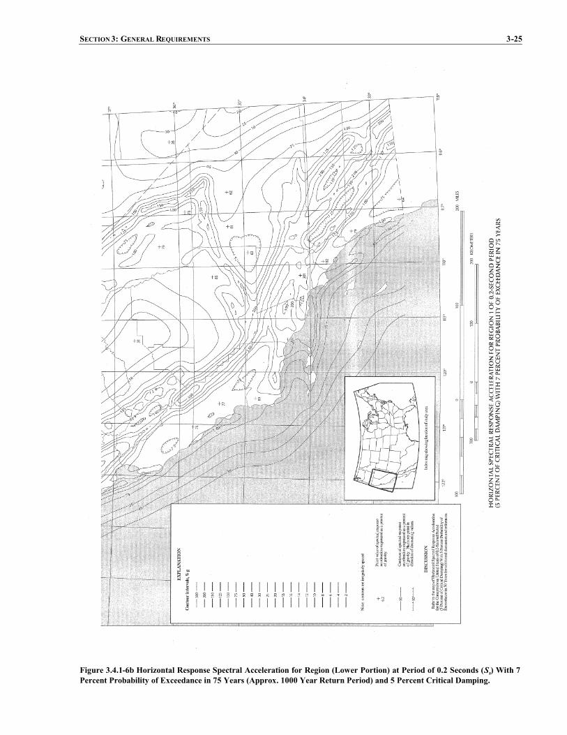
SECTION 3: GENERAL REQUIREMENTS 3-25
Figure 3.4.1-6b Horizontal Response Spectral Acceleration for Region (Lower Portion) at Period of 0.2 Seconds (Ss) With 7Percent Probability of Exceedance in 75 Years (Approx. 1000 Year Return Period) and 5 Percent Critical Damping.

3-26 AASHTO GUIDE SPECIFICATION FOR LRFDSEISMIC BRIDGE DESIGN
Figure 3.4.1-7a Horizontal Response Spectral Acceleration for Region 1 (Upper Portion) at Period of 1.0 Seconds (S1) With 7Percent Probability of Exceedance in 75 Years (Approx. 1000 Year Return Period) and 5 Percent Critical Damping.

SECTION 3: GENERAL REQUIREMENTS 3-27
Figure 3.4.1-7b Horizontal Response Spectral Acceleration for Region (Lower Portion) at Period of 1.0 Seconds (S1) With 7Percent Probability of Exceedance in 75 Years (Approx. 1000 Year Return Period) and 5 Percent Critical Damping.

3-28 AASHTO GUIDE SPECIFICATION FOR LRFDSEISMIC BRIDGE DESIGN
Figure 3.4.1-8 Peak Horizontal Ground Acceleration for Region 2 With 7 Percent Probability of Exceedance in 75 Years(Approx. 1000 Year Return Period).
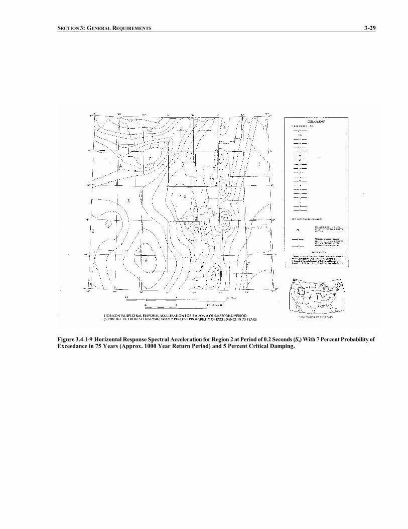
SECTION 3: GENERAL REQUIREMENTS 3-29
Figure 3.4.1-9 Horizontal Response Spectral Acceleration forRegion 2 at Period of 0.2 Seconds (Ss)With 7 Percent Probability ofExceedance in 75 Years (Approx. 1000 Year Return Period) and 5 Percent Critical Damping.

3-30 AASHTO GUIDE SPECIFICATION FOR LRFDSEISMIC BRIDGE DESIGN
Figure 3.4.1-10 Horizontal Response Spectral Acceleration for Region 2 at Period of 1.0 Seconds (S1)With 7 Percent Probabilityof Exceedance in 75 Years (Approx. 1000 Year Return Period) and 5 Percent Critical Damping.

SECTION 3: GENERAL REQUIREMENTS 3-31
Figure 3.4.1-11 Peak Horizontal Ground Acceleration for Region 3 With 7 Percent Probability of Exceedance in 75 Years(Approx. 1000 Year Return Period).

3-32 AASHTO GUIDE SPECIFICATION FOR LRFDSEISMIC BRIDGE DESIGN
Figure 3.4.1-12 Horizontal Response Spectral Acceleration for Region 3 at Period of 0.2 Seconds (Ss)With 7 Percent Probabilityof Exceedance in 75 Years (Approx. 1000 Year Return Period) and 5 Percent Critical Damping.

SECTION 3: GENERAL REQUIREMENTS 3-33
Figure 3.4.1-13 Horizontal Response Spectral Acceleration for Region 3 at Period of 1.0 Seconds (S1)With 7 Percent Probabilityof Exceedance in 75 Years (Approx. 1000 Year Return Period) and 5 Percent Critical Damping.

3-34 AASHTO GUIDE SPECIFICATION FOR LRFDSEISMIC BRIDGE DESIGN
Figure 3.4.1-14 Peak Horizontal Ground Acceleration for Region 4 With 7 Percent Probability of Exceedance in 75 Years(Approx. 1000 Year Return Period).

SECTION 3: GENERAL REQUIREMENTS 3-35
Figure 3.4.1-15 Horizontal Response Spectral Acceleration for Region 4 at Periods of 0.2 and 1.0 Seconds (Ss and S1) With 7Percent Probability of Exceedance in 75 Years (Approx. 1000 Year Return Period) and 5 Percent Critical Damping.

3-36 AASHTO GUIDE SPECIFICATION FOR LRFDSEISMIC BRIDGE DESIGN
Figure 3.4.1-16 PeakHorizontal Ground Acceleration forAlaskaWith 7 Percent Probability of Exceedance in 75Years (Approx.1000 Year Return Period).
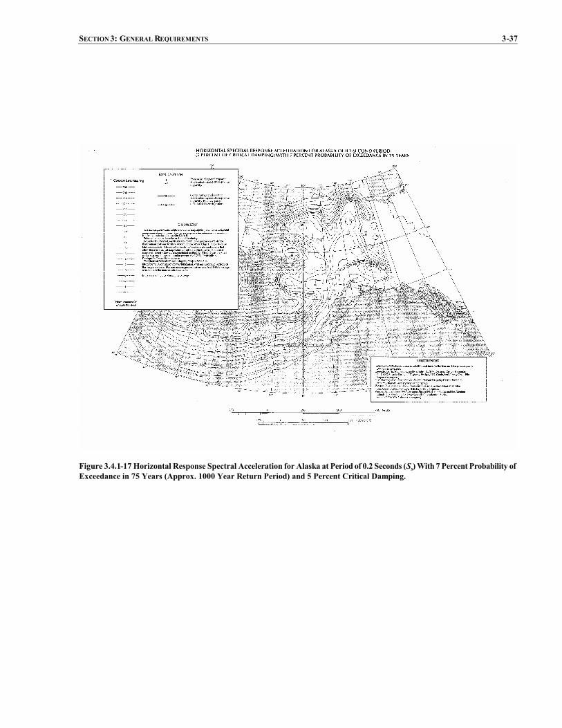
SECTION 3: GENERAL REQUIREMENTS 3-37
Figure 3.4.1-17 Horizontal Response Spectral Acceleration for Alaska at Period of 0.2 Seconds (Ss)With 7 Percent Probability ofExceedance in 75 Years (Approx. 1000 Year Return Period) and 5 Percent Critical Damping.

3-38 AASHTO GUIDE SPECIFICATION FOR LRFDSEISMIC BRIDGE DESIGN
Figure 3.4.1-18 Horizontal Response Spectral Acceleration for Alaska at Period of 1.0 Seconds (S1)With 7 Percent Probability ofExceedance in 75 Years (Approx. 1000 Year Return Period) and 5 Percent Critical Damping.

SECTION 3: GENERAL REQUIREMENTS 3-39
Figure 3.4.1-19 Peak Horizontal Ground Acceleration for Hawaii With 7 Percent Probability of Exceedance in 75 Years(Approx. 1000 Year Return Period).

3-40 AASHTO GUIDE SPECIFICATION FOR LRFDSEISMIC BRIDGE DESIGN
Figure 3.4.1-20 Horizontal Response Spectral Acceleration for Hawaii at Periods of 0.2 and 1.0 Seconds (Ss and S1) With 7Percent Probability of Exceedance in 75 Years (Approx. 1000 Year Return Period) and 5 Percent Critical Damping.

SECTION 3: GENERAL REQUIREMENTS 3-41
Figure 3.4.1-21 Peak Horizontal Ground Acceleration for Puerto Rico, Culebra, Vieques, St. Thomas, St. John, and St. CroixWith 7 Percent Probability of Exceedance in 75 Years (Approx. 1000 Year Return Period).

3-42 AASHTO GUIDE SPECIFICATION FOR LRFDSEISMIC BRIDGE DESIGN
Figure 3.4.1-22 Horizontal Response Spectral Acceleration for Puerto Rico, Culebra, Vieques, St. Thomas, St. John, and St.Croix at Periods of 0.2 and 1.0 Seconds (Ss and S1) With 7 Percent Probability of Exceedance in 75 Years (Approx. 1000 YearReturn Period) and 5 Percent Critical Damping.

SECTION 3: GENERAL REQUIREMENTS 3-43
3.4.2 Site Effects on Ground Motions
The generalized site classes and site factors describedin this article shall be used with the general procedure forconstructing response spectra described in Article 3.4.1.Site-specific analysis of soil response effects shall beconducted where required byArticle 3.4 and in accordancewith the requirements in Article 3.4.3 and Table 3.4.2.1-1Site Class Definitions.
If geological conditions at the abutments andintermediate piers result in different soil classification,then the design response spectra may be determined basedupon the site-specific procedures outlined in Article 3.4.3.In lieu of the site-specific procedures and under guidancefrom the geotechnical engineer, the design responsespectra may be determined as the envelope of theindividual response spectra at each support.
C3.4.2
The site classes and site factors described in thisarticle were originally recommended at a site responseworkshop in 1992 (Martin, ed., 1994). Subsequently theywere adopted in the seismic design criteria of Caltrans , the1994 and the 1997 edition of the NEHRP RecommendedProvisions for Seismic Regulations for New Buildings andOther Structures (BSSC, 1995, 1998), the 1997 UniformBuilding Code (ICBO, 1997) and the 2000 InternationalBuilding Code (ICC, 2000). The bases for the adopted siteclasses and site factors are described byMartin and Dobry(1994) and Rinne (1994).
Procedures described in this article were originallydeveloped for computing ground motions at the groundsurface for relatively uniform site conditions. Dependingon the site classification and the level of the groundmotion, the motion at the surface could be different fromthe motion at depth. This creates some question as to thelocation of the motion to use in the bridge design. It is alsopossible that the soil conditions at the two abutments aredifferent or they differ at the abutments and interior piers.An example would be where one abutment is on firmground or rock and the other is on a loose fill. Thesevariations are not always easily handled by simplifiedprocedures described in this commentary. For criticalbridges it may be necessary to usemore rigorous numericalmodeling to represent these conditions. The decision to usemore rigorous numerical modeling should be made afterdetailed discussion of the benefits and limitations of morerigorous modeling between the bridge and geotechnicalengineers.
3.4.2.1 Site Class Definitions
The site shall be classified as one of the followingclasses given in Table 1. Procedures given in Article3.4.2.2 shall be used to determine the average condition forvarying profile conditions.
For preliminary design Site Classes E or F should notbe assumed unless the authority having jurisdictiondetermines that Site Classes E or F could be present at thesite or in the event that Site Classes E or F are establishedby geotechnical data.
The shear wave velocity for rock, Site Class B, shallbe either measured on site or estimated on the basis ofshear wave velocities in similar competent rock withmoderate fracturing and weathering. Softer and morehighly fractured and weathered rock shall either bemeasured on site for shear wave velocity or classified asSite Class C.
The hard rock, Site Class A, category shall besupported by shear wave velocity measurements either onsite or on profiles of the same rock type in the sameformation with an equal or greater degree of weatheringand fracturing. Where hard rock conditions are known tobe continuous to a depth of 100 ft. surficial shear wave
C3.4.2.1
Steps for Classifying a Site (also see Table 3.4.2-1):
Step 1: Check the site against the three categories ofSite Class F, requiring site-specific evaluation. If the sitecorresponds to any of these categories, classify the site asSite Class F and conduct a site-specific evaluation.
Step 2: Categorize the site using one of the followingthree methods, with sv , N , and us computed in all casesas specified by the definitions in Article 3.4.2.2:
Method a: sv for the top 100 ft. ( sv method)
Method b: N for the top 100 ft. ( N method)
Method c: chN for cohesionless soil layers (PI<20)in the top 100 ft. and average us forcohesive soil layers (PI > 20) in the top100 ft. ( us method)
3-44 AASHTO GUIDE SPECIFICATION FOR LRFDSEISMIC BRIDGE DESIGN
velocity measurements may be extrapolated to assess sv .The rock categories, Site Classes A andB, shall not be
used if there is more than 10 ft. of soil between the rocksurface and the bottom of the spread footing or matfoundation.
PI shall be taken as the plasticity index specified inASTMD4318-93. w shall be taken as the moisture contentin percent specified in ASTM D2216-92.
chN and us are averaged over the respective thicknessof cohesionless and cohesive soil layers within the upper100 ft. Refer to Article 3.4.2.2 for equations forcalculating average parameter values for the methods a, b,and c above. If method c is used, the site class isdetermined as the softer site class resulting from theaveraging to obtain chN and us (for example, if chN wereequal to 20 blows/ft. and us were equal to 800 psf, the sitewould classify as E in accordance with Table 3.4.2-1).Note that when using method b, N values are for bothcohesionless and cohesive soil layers within the upper 100ft.
As described in Article C3.4.2.2, it may beappropriate in some cases to define the ground motion atdepth, below a soft surficial layer, if the surficial layerwould not significantly influence bridge response. In thiscase, the Site Class may be determined on the basis of thesoil profile characteristics below the surficial layer.
Within Site Class F (soils requiring site-specificevaluation), one category has been deleted in thesespecifications from the four categories contained in thepreviously cited codes and documents. This categoryconsists of soils vulnerable to potential failure or collapseunder seismic loading, such as liquefiable soils, quick andhighly sensitive clays, and collapsible, weakly cementedsoils. It was judged that special analyses for the purpose ofrefining site ground-motion amplifications for these soilswas too severe a requirement for ordinary bridge designbecause such analyses would require utilization ofeffective stress and strength-degrading nonlinear analysesthat are difficult to conduct. Also, limited case-historydata and analysis results indicate that liquefaction reducesspectral response rather than increases it, except at longperiods in some cases. Because of the general reduction inresponse spectral amplitudes due to liquefaction, thedesigner may wish to consider special analysis of siteresponse for liquefiable soil sites to avoid excessiveconservatism in assessing bridge inertia loads whenliquefaction occurs. Site-specific analyses are required formajor or very important structures in some cases (Article3.4), so that appropriate analysis techniqueswould be usedfor such structures. The deletion of liquefiable soils fromSite Class F only affects the requirement to conduct site-specific analyses for the purpose of determining groundmotion amplification through these soils. It is still requiredto evaluate liquefaction occurrence and its effect on abridge as specified in Article 6.8.

SECTION 3: GENERAL REQUIREMENTS 3-45
Table 3.4.2.1-1 Site Class Definitions.
Site Class Soil Type and Profile
A Hard rock with measured shear wave velocity, �sv 5,000 ft/sec.
B Rock with 2,500 ft/sec < sv < 5,000 ft/sec.
C Very dense soil and soil rock with 1,200 ft/sec < sv < 2,500 ft/sec, or with either N > 50 blows/ft, or us > 2.0 ksf.
D Stiff soil with 600 ft/sec < sv < 1,200 ft/sec, or with either 15 < N < 50 blows/ft, or 1.0 < us < 2.0 ksf.
E Soil profile with sv < 600 ft/sec or with either N < 15 blows/ft or us < 1.0 ksf, or any profile with more than 10 ft
of soft clay defined as soil with PI > 20, w > 40 percent and us < 0.5 ksf.
F Soils requiring site-specific evaluations, such as:
Peats or highly organic clays (H > 10 ft of peat or highly organic clay where H = thickness of soil)Very high plasticity clays (H > 25 ft with PI > 75)Very thick soft/medium stiff clays (H >120 ft)
Exceptions:
Where the soil properties are not known in sufficient detail to determine the site class, a site investigation shall be undertakensufficient to determine the site class. Site classes E or F should not be assumed unless the authority having jurisdiction determinesthat site classes E or F could be present at the site or in the event that site classes E or F are established by geotechnical data.
where:
sv = average shear wave velocity for the upper 100 ft of the soil profile
N = average Standard Penetration Test (SPT) blow count (blows/ft) (ASTM D1586) for the upper 100 ft of the soil profile
us = average undrained shear strength in ksf (ASTM D2166 or D2850) for the upper 100 ft of the soil profile
PI = plasticity index (ASTM D4318)
w = moisture content (ASTM D2216)
3.4.2.2 Definitions of Site Class Parameters
The definitions presented below shall be taken toapply to the upper 100 ft. of the site profile. Profilescontaining distinctly different soil layers shall besubdivided into those layers designated by a number thatranges from 1 to n at the bottom where there are a total ofn distinct layers in the upper 100 ft.
The average sv for the site profile shall be taken as:
1
1
n
ii
s ni
i si
dv
dv
�
�
��
�(3.4.2.2-1)
where:
C3.4.2.2
An alternative to applying Eqs. 2, 3, and 4 to obtainvalues for N , chN and us is to convert the N-values or suvalues into estimated shear wave velocities and then toapply Eq. 1. Procedures given in Kramer (1996) can beused for these conversions.
If the site profile is particularly non-uniform, or if theaverage velocity computed in this manner does not appearreasonable, or if the project involves special design issues,it may be desirable to conduct shear-wave velocitymeasurements. In all evaluations of site classification, theshear-wave velocity should be viewed as the fundamentalsoil property, as this was used when conducting theoriginal studies defining the site categories.
Depth of Motion Determination. For short bridges thatinvolve a limited number of spans, the motion at theabutment will generally be the primary mechanism bywhich energy is transferred from the ground to the bridge

3-46 AASHTO GUIDE SPECIFICATION FOR LRFDSEISMIC BRIDGE DESIGN
1
n
ii
d�� = thickness of upper soil layers = 100 ft.
di = thickness of “ith” soil layer (ft.)
n = total number of distinctive soil layers in theupper 100 ft. of the site profile below thebridge foundation
�si = shear wave velocity of “ith” soil layer(ft./sec.)
� = any one of the layers between 1 and n
N shall be taken as:
1
1
n
iin
i
i i
dN
dN
�
�
��
�(3.4.2.2-2)
where:
Ni = standard penetration resistance as measureddirectly in the field, uncorrected blow count, of“ith” soil layer not to exceed 100 (blows/ft.)
chN shall be taken as:
1
1
m
ii
ch mi
i i
dN
dN
�
�
��
�(3.4.2.2-3)
where:
m = total number of cohesionless soil layers in theupper 100 ft. of the site profile below the bridgefoundation
us shall be taken as:
1
1
k
ii
u ki
i ui
ds
ds
�
�
��
�(3.4.2.2-4)
where:
k = total number of cohesive soil layers in the upper100 ft. of the site profile below the bridgefoundation
superstructure. If the abutment is backed by an earthapproach fill, the site classification should be determinedat the base of the approach fill. The potential effects of theapproach fill overburden pressure on the shear-wavevelocity of the soil should be accounted for in thedetermination of site classification.
For long bridges it may be necessary to determine thesite classification at an interior pier. If this pier issupported on spread footings, then the motion computed atthe ground surface is appropriate. However, if deepfoundations (i.e., driven piles or drilled shafts) are used tosupport the pier, then the location of the motion willdepend on the horizontal stiffness of the soil-cap systemrelative to the horizontal stiffness of the soil-pile system. Ifthe pile cap is the stiffer of the two, then the motion shouldbe defined at the pile cap. If the pile cap provides littlehorizontal stiffness or if there is no pile cap (i.e., pileextension), then the controlling motion will likely be atsome depth below the ground surface. Typically this willbe approximately 4 to 7 pile diameters below the pile capor where a large change in soil stiffness occurs. Thedetermination of this elevation requires considerablejudgment and should bediscussed by the geotechnical andbridge engineers.
For cases where the controlling motion is moreappropriately specified at depth, site-specific groundresponse analyses can be conducted to establish groundmotions at the point of fixity. This approach oralternatives to this approach should be used only with theowner’s approval.

SECTION 3: GENERAL REQUIREMENTS 3-47
sui = undrained shear strength of “ith” soil layer not toexceed 5 (ksf)
3.4.2.3 Site Coefficients
Site coefficients for the peak ground acceleration(Fpga), short-period range (Fa) and for the long-periodrange (Fv) shall be taken as specified in Tables 1 and 2.Application of these coefficients to determine elasticseismic response coefficients of ground motion shall be asspecified in Article 3.4.1.
Table 3.4.2.3-1 Values of Fpga andFa as a Function of Site Class and Mapped Peak Ground Acceleration or Short-PeriodSpectral Acceleration Coefficient.
Mapped Peak Ground Acceleration or Spectral Response Acceleration Coefficient at ShortPeriods
Site ClassPGA�� 0.10
Ss � 0.25
PGA = 0.20
Ss = 0.50
PGA = 0.30
Ss = 0.75
PGA = 0.40
Ss = 1.00
PGA � 0.50
Ss � 1.25
A 0.8 0.8 0.8 0.8 0.8
B 1.0 1.0 1.0 1.0 1.0
C 1.2 1.2 1.1 1.0 1.0
D 1.6 1.4 1.2 1.1 1.0
E 2.5 1.7 1.2 0.9 0.9
F a a a a a
Table notes: Use straight line interpolation for intermediate values of PGA and Ss, where PGA is the peak groundacceleration and Ss is the spectral acceleration coefficient at 0.2 sec. obtained from the ground motion maps.a: Site-specific geotechnical investigation and dynamic site response analyses shall be performed (Article 3.4.3).
Table 3.4.2.3-2 Values of Fv as a Function of Site Class and Mapped 1 Second Period Spectral Acceleration Coefficient.
Mapped Spectral Response Acceleration Coefficient at 1 Second Periods
Site Class S1 � 0.1 S1 = 0.2 S1 = 0.3 S1 = 0.4 S1 � 0.5
A 0.8 0.8 0.8 0.8 0.8
B 1.0 1.0 1.0 1.0 1.0
C 1.7 1.6 1.5 1.4 1.3
D 2.4 2.0 1.8 1.6 1.5
E 3.5 3.2 2.8 2.4 2.4
F a a a a a
Table notes: Use straight line interpolation for intermediate values of S1, where S1 is the spectral accelerationcoefficient at 1.0 sec. obtained from the ground motion maps.a: Site-specific geotechnical investigation and dynamic site response analyses shall be performed (Article 3.4.3).
3-48 AASHTO GUIDE SPECIFICATION FOR LRFDSEISMIC BRIDGE DESIGN
3.4.3 Response Spectra Based on Site-SpecificProcedures
A site-specific procedure to develop design responsespectra of earthquake ground motions shall be performedwhen required by Article 3.4 and may be performed forany site. The site-specific probabilistic ground-motionanalysis shall be conducted in a manner to generate auniform-hazard acceleration response spectrumconsidering a 7% probability of exceedance in 75 years forspectral values over the entire period range of interest.This analysis shall establish the following:
� The contributing seismic sources,
� An upper-bound earthquake magnitude for eachsource zone,
� Median attenuation relations for accelerationresponse spectral values and their associatedstandard deviations,
� Amagnitude-recurrence relation for each sourcezone, and
� A fault-rupture-length relation for eachcontributing fault.
Uncertainties in sourcemodeling and parameter valuesshall be taken into consideration. Detailed documentationof ground-motion analysis shall be provided and shall bepeer reviewed (Article C3.4.1).
Where analyses to determine site soil response effectsare required by Articles 3.4 and 3.4.2.1 for Site Class Fsoils, the influence of the local soil conditions shall bedetermined based on site-specific geotechnicalinvestigations and dynamic site response analyses.
For sites located within 6 miles of an active surface orshallow fault, as depicted in the USGS Active Fault Map,studies shall be considered to quantify near-fault effects onground motions to determine if these could significantlyinfluence the bridge response. The fault-normalcomponent of near-field (D < 6 miles) motion may containrelatively long-duration velocity pulses which can causesevere nonlinear structural response, predictable onlythrough nonlinear time-history analyses. For this case therecorded near-field horizontal components of motion shallbe transformed into principal components beforemodifiedto be response-spectrum-compatible.
A deterministic spectrum may be utilized in regionshaving known active faults if the deterministic spectrum isno less than 2/3 of the probabilistic spectrum in the regionof 0.5TF to 2TF of the spectrum where TF is the bridgefundamental period. Where use of a deterministicspectrum is appropriate, the spectrum shall be either:
� the envelope of a median spectra calculated for
C3.4.3
The intent in conducting a site-specific probabilisticground motion study is to develop ground motions that aremore accurate for the local seismic and site conditions thancan be determined from national ground motion maps andthe procedure of Article 3.4.1. Accordingly, such studiesshould be comprehensive and incorporate current scientificinterpretations at a regional scale. Because there aretypically scientifically credible alternatives formodels andparameter values used to characterize seismic sources andground-motion attenuation, it is important to incorporatethese uncertainties formally in a site-specific probabilisticanalysis. Examples of these uncertainties include seismicsource location, extent and geometry; maximumearthquake magnitude; earthquake recurrence rate; andground-motion attenuation relationship.
Near-fault effects on horizontal response spectrainclude:
� Higher ground motions due to the proximity ofthe active fault,
� Directivity effects that increase ground motionsfor periods greater than 0.5 second if the faultrupture propagates toward the site, and
� Directionality effects that increase groundmotions for periods greater than 0.5 second in thedirection normal (perpendicular) to the strike ofthe fault.
If the active fault is included and appropriatelymodeled in the development of national ground motionmaps, then the first effect is already included in thenational ground motion maps. The second and thirdeffects are not included in the national maps. These effectsare significant only for periods longer than 0.5 second andnormally would be evaluated only for essential or criticalbridges having natural periods of vibration longer than 0.5second. Further discussion of the second and third effectsare contained in Somerville (1997) and Somerville et al.(1997). The ratio of vertical-to-horizontal groundmotionsincreases for short-period motions in the near-faultenvironment.

SECTION 3: GENERAL REQUIREMENTS 3-49
characteristic maximum magnitude earthquakeson known active faults; or
� a deterministic spectra may be defined for eachfault, and in the absence of a clearly controllingspectra, each spectrum should be used.
Where response spectra are determined from a site-specific study, the spectra shall not be lower than two-thirds of the response spectra determined using the generalprocedure of Article 3.4.1 in the region of 0.5TF to 2TF ofthe spectrum where TF is the bridge fundamental period.
3.4.4 Acceleration Time-Histories
The development of time histories shall meet therequirements of this article. The developed time historiesshall have characteristics that are representative of theseismic environment of the site and the local siteconditions.
Response-spectrum-compatible time histories shall beused as developed from representative recorded motions.Analytical techniques used for spectrummatching shall bedemonstrated to be capable of achieving seismologicallyrealistic time series that are similar to the time series of theinitial time histories selected for spectrum matching.
Where recorded time histories are used, they shall bescaled to the approximate level of the design responsespectrum in the period range of significance unlessotherwise approved by the owner. Each time history shallbe modified to be response-spectrum compatible using thetime-domain procedure.
At least three response-spectrum-compatible timehistories shall be used for each component of motion inrepresenting the design earthquake (groundmotions having7% probability of exceedance in 75 years). The issue ofrequiring all three orthogonal components (x, y, and z) ofdesign motion to be input simultaneously shall beconsidered as a requirement when conducting a nonlineartime-history analysis. The design actions shall be taken asthe maximum response calculated for the three groundmotions in each principal direction. If aminimumof seventime histories are used for each component of motion, thedesign actions may be taken as the mean responsecalculated for each principal direction.
For near-field sites (D < 6 miles) the recordedhorizontal components of motion selected should representa near-field condition and that they should be transformedinto principal components before making them response-spectrum-compatible. The major principal componentshould then be used to represent motion in the fault-normaldirection and the minor principal component should beused to represent motion in the fault-parallel direction.
C3.4.4
Characteristics of the seismic environment of the siteto be considered in selecting time-histories include:tectonic environment (e.g., subduction zone; shallowcrustal faults in western United States or similar crustalenvironment; eastern United States or similar crustalenvironment); earthquakemagnitude; type of faulting (e.g.,strike-slip; reverse; normal); seismic-source-to-sitedistance; local site conditions; and design or expectedground-motion characteristics (e.g., design responsespectrum; duration of strong shaking; and special ground-motion characteristics such as near-fault characteristics).Dominant earthquake magnitudes and distances, whichcontribute principally to the probabilistic design responsespectra at a site, as determined from national groundmotion maps, can be obtained from deaggregationinformation on the U.S. Geological Survey website:http://geohazards.cr.usgs.gov/.
It is desirable to select time-histories that have beenrecorded under conditions similar to the seismic conditionsat the site listed above, but compromises are usuallyrequired because of the multiple attributes of the seismicenvironment and the limited data bank of recorded time-histories. Selection of time-histories having similarearthquake magnitudes and distances, within reasonableranges, are especially important parameters because theyhave a strong influence on response spectral content,response spectral shape, duration of strong shaking, andnear-source ground-motion characteristics. It is desirablethat selected recorded motions be somewhat similar inoverall ground motion level and spectral shape to thedesign spectrum to avoid using very large scaling factorswith recorded motions and very large changes in spectralcontent in the spectrum-matching approach. If the site islocated within 6 miles of an active fault, then intermediate-to-long-period ground-motion pulses that are characteristicof near-source time-histories should be included if thesetypes of ground motion characteristics could significantlyinfluence structural response. Similarly, the high short-period spectral content of near-source vertical groundmotions should be considered.
Ground-motion modeling methods of strong-motionseismology are being increasingly used to supplement the

3-50 AASHTO GUIDE SPECIFICATION FOR LRFDSEISMIC BRIDGE DESIGN
recorded ground-motion database. These methods areespecially useful for seismic settings for which relativelyfew actual strong-motion recordings are available, such asin the central and eastern United States. Throughanalytical simulation of the earthquake rupture and wave-propagation process, these methods can produceseismologically reasonable time series.
Response spectrum matching approaches includemethods in which time series adjustments are made in thetime domain (Lilhanand and Tseng, 1988; Abrahamson,1992) and those in which the adjustments are made in thefrequency domain (Gasparini and Vanmarcke, 1976; Silvaand Lee, 1987; Bolt and Gregor, 1993). Both of theseapproaches can be used to modify existing time-histories toachieve a close match to the design response spectrumwhile maintaining fairly well the basic time-domaincharacter of the recorded or simulated time-histories. Tominimize changes to the time-domain characteristics, it isdesirable that the overall shape of the spectrum of therecorded time-history not be greatly different from theshape of the design response spectrum and that the time-history initially be scaled so that its spectrum is at theapproximate level of the design spectrum before spectrummatching.
When developing three-component sets of timehistories by simple scaling rather than spectrummatching,it is difficult to achieve a comparable aggregate match tothe design spectra for each component of motion whenusing a single scaling factor for each time-history set. It isdesirable, however, to use a single scaling factor topreserve the relationship between the components.Approaches for dealing with this scaling issue include:
� Use of a higher scaling factor to meet theminimum aggregate match requirement for onecomponent while exceeding it for the other two,
� Use of a scaling factor to meet the aggregatematch for the most critical component with thematch somewhat deficient for other components,and
� Compromising on the scaling by using differentfactors as required for different components of atime-history set.
While the second approach is acceptable, it requirescareful examination and interpretation of the results andpossibly dual analyses for application of the horizontalhigher horizontal component in each principal horizontaldirection.
The requirements for the number of time histories tobe used in nonlinear inelastic dynamic analysis and for theinterpretation of the results take into account thedependence of response on the time domain character ofthe time histories (duration, pulse shape, pulse sequencing)in addition to their response spectral content.

SECTION 3: GENERAL REQUIREMENTS 3-51
Additional guidance on developing acceleration timehistories for dynamic analysis may be found inpublications by the Caltrans Seismic Advisory BoardAdhoc Committee (CSABAC) on Soil-Foundation-Structure Interaction (1999) and the U.S. Army Corps ofEngineers (2000). CSABAC (1999) also provides detailedguidance on modeling the spatial variation of groundmotion between bridge piers and the conduct of seismicsoil-foundation-structure interaction (SFSI) analyses. Bothspatial variations of ground motion and SFSI maysignificantly affect bridge response. Spatial variationsinclude differences between seismic wave arrival times atbridge piers (wave passage effect), ground motionincoherence due to seismic wave scattering, anddifferential site response due to different soil profiles atdifferent bridge piers. For long bridges, all forms ofspatial variations may be important. For short bridges,limited information appears to indicate that wave passageeffects and incoherence are, in general, relativelyunimportant in comparison to effects of differential siteresponse (Shinozuka et al., 1999; Martin, 1998).Somerville et al. (1999) provide guidance on thecharacteristics of pulses of ground motion that occur intime histories in the near-fault region.
3.5 SELECTION OF SEISMIC DESIGNCATEGORY (SDC)
Each bridge shall be assigned to one of four SeismicDesign Categories (SDC), A through D, based on the onesecond period design spectral acceleration for the designearthquake (SD1 refer to Article 3.4.1) as shown in Table 1.
C3.5
The Seismic Hazard Level is defined as a function ofthe magnitude of the ground surface shaking as expressedby FvS1 .
The Seismic Design Category reflects the variation inseismic risk across the country and is used to permitdifferent requirements for methods of analysis, minimumsupport lengths, column design details, and foundation andabutment design procedures.
Table 3.5-1 Partitions for Seismic Design Categories A, B,C and D.
Value of SD1 = FvS1 SDC
SD1 < 0.15 A0.15 � SD1 < 0.30 B0.30 � SD1 < 0.50 C0.50 � SD1 D
The five requirements for each of the proposedSeismic Design Categories shall be taken as shown inFigure 1 and described below. For both single spanbridges and bridges classified as SDC A the connectionsshall be designed for specified forces in Article 4.5 andArticle 4.6 respectively, and shall also meet minimumsupport length requirements of Article 4.12.
� SDC A
a. No identification of ERS according to
.

3-52 AASHTO GUIDE SPECIFICATION FOR LRFDSEISMIC BRIDGE DESIGN
Article 3.3
b. No Demand Analysis
c. No Implicit Capacity Check Needed
d. No Capacity Design Required
e. MinimumDetailing requirements for supportlength and superstructure/substructureconnection design force
� SDC B
f. No Identification of ERS according toArticle 3.3
g. Demand Analysis
h. Implicit Capacity Check Required(displacement, P-�� support length)
i. No Capacity Design Required except forcolumn shear requirement
j. SDC B Level of Detailing
� SDC C
k. Identification of ERS
l. Demand Analysis
m. Implicit Capacity Check Required(displacement, P-�� support length)
n. Capacity Design Required includingcolumn shear requirement
o. SDC C Level of Detailing
� SDC D
p. Identification of ERS
q. Demand Analysis
r. Displacement Capacity Required usingPushover Analysis (check P-� and supportlength)
s. Capacity Design Required including columnshear requirement
t. SDC D Level of Detailing

SECTION 3: GENERAL REQUIREMENTS 3-53
SDC "A"
SDC "B"
Implicit Capacity
MinimumRequirements
DemandAnalysis Implicit Capacity
Yes
No
Yes1D
C � SDC B Detailing CompleteYes
SDC "C"
No No
YesDemandAnalysis 1D
C � Capacity Design SDC C DetailingYes
Complete
SDC "D"
NoNo
Demand Analysis PushoverCapacity Analysis
1DC � Capacity Design SDC D Detailing
YesComplete
No
Adust BridgeCharacteristics
Depends on Adjustments
Yes
IdentifyERS
IdentifyERS
Complete
Figure 3.5-1 Seismic Design Category (SDC) Core Flowchart.
3.6 TEMPORARY AND STAGEDCONSTRUCTION
Any bridge or partially constructed bridge that isexpected to be temporary for more than five years shall bedesigned using the requirements for permanent structuresand shall not use the provisions of this Article.
Temporary bridges expected to carry vehicular trafficor pedestrian bridges over roads carrying vehicular trafficshall satisfy the Performance Criteria defined in Article3.2. The provisions also apply to those bridges that areconstructed in stages and expected to carry traffic and/orpass over routes that carry traffic. The design responsespectra given in Article 3.4 may be reduced by a factor ofnot more than 2.5 in order to calculate the componentelastic forces and displacements. The Seismic DesignCategory of the temporary bridge shall be obtained basedon the reduced/modified response spectrum except that atemporary bridge classified in SDCB, C or D based on theunreduced spectrum can not be reclassified to SDC Abased on the reduced/modified spectrum. Therequirements for each of the Seismic Design Categories Athrough D shall be met as defined in Article 3.5. Responsespectra for construction sites that are within 6 miles of anactive fault (see Article 3.4) shall be the subject of specialstudy.
C3.6
The option to use a reduced acceleration coefficient isprovided to reflect the limited exposure period.

3-54 AASHTO GUIDE SPECIFICATION FOR LRFDSEISMIC BRIDGE DESIGN
3.7 LOAD AND RESISTANCE FACTORS
Use load factors of 1.0 for all permanent loads.Unless otherwise noted, all � factors shall be taken as 1.0
C3.7
Historically the load factor for live load has beentaken as zero for the earthquake load combination exceptwhere heavy truck traffic, high ADT or long structurelength are anticipated.

SECTION 4: ANALYSIS AND DESIGN REQUIREMENTS
TABLE OF CONTENTS
4-i
4.1 GENERAL........................................................................................................................................................ 4-14.1.1 Balanced Stiffness SDC D...................................................................................................................... 4-14.1.2 Balanced Frame Geometry SDC D......................................................................................................... 4-44.1.3 Adjusting Dynamic Characteristics......................................................................................................... 4-44.1.4 End Span Considerations........................................................................................................................ 4-5
4.2 SELECTION OF ANALYSIS PROCEDURE TO DETERMINE SEISMIC DEMAND ................................ 4-54.2.1 Special Requirements for Curved Bridges .............................................................................................. 4-64.2.2 Limitations and Special Requirements.................................................................................................... 4-6
4.3 DETERMINATION OF SEISMIC LATERAL DIPSLACMENT DEMANDS............................................... 4-74.3.1 Horizontal Ground Motions.................................................................................................................... 4-74.3.2 Displacement Modification for Other Than 5% Damped Bridges .......................................................... 4-74.3.3 Displacement Magnification for Short Period Structures ....................................................................... 4-8
4.4 COMBINATION OF ORTHOGONAL SEISMIC DISPLACEMENT DEMANDS....................................... 4-94.5 DESIGN REQUIREMENTS FOR SINGLE SPAN BRIDGES ....................................................................... 4-104.6 DESIGN REQUIREMENTS FOR SEISMIC DESIGN CATEGORY A......................................................... 4-104.7 DESIGN REQUIREMENTS FOR SEISMIC DESIGN CATEGORIES B, C, AND D ................................... 4-11
4.7.1 Design Methods for Lateral Seismic Displacement Demands ................................................................. 4-114.7.2 Vertical Ground Motion, Design Requirements for SDC D ................................................................... 4-12
4.8 STRUCTURE DISPLACEMENT DEMAND/CAPACITY FOR SDC B, C, AND D..................................... 4-124.8.1 Local Displacement Capacity for SDC B and C ..................................................................................... 4-134.8.2 Local Displacement Capacity for SDC D ............................................................................................... 4-14
4.9 MEMBER DUCTILITY REQUIREMENT FOR SDC D ................................................................................ 4-144.10 COLUMN SHEAR REQUIREMENTS FOR SDC B, C, AND D.................................................................. 4-154.11 CAPACITY DESIGN REQUIREMENT FOR SDC C AND D ..................................................................... 4-15
4.11.1 Capacity Design.................................................................................................................................... 4-154.11.2 Plastic Hinging Forces .......................................................................................................................... 4-154.11.3 Single Columns and Piers ..................................................................................................................... 4-184.11.4 Bents With Two or More Columns....................................................................................................... 4-184.11.5 P-�Capacity Requirement for SDC C and D ....................................................................................... 4-194.11.6 Analytical Plastic Hinge Length ........................................................................................................... 4-214.11.7 Reinforced Concrete Column Plastic Hinge Region ............................................................................. 4-224.11.8 Steel Column Plastic Hinge Region ...................................................................................................... 4-22
4.12 MINIMUM SUPPORT LENGTH REQUIREMENTS .................................................................................. 4-224.12.1 Seismic Design Categories A, B, and C................................................................................................ 4-224.12.2 Seismic Design Category D.................................................................................................................. 4-23
4.13 SUPPORT RESTRAINTS FOR SDC C AND D ........................................................................................... 4-244.13.1 Longitudinal Restrainers ....................................................................................................................... 4-244.13.2 Simple Span Superstructures ................................................................................................................ 4-244.13.3 Detailing Restrainers............................................................................................................................. 4-25
4.14 SUPERSTRUCTURE SHEAR KEYS............................................................................................................ 4-25
TO BE UPDATED BY AASHTO PUBLICATIONS


SECTION 4
ANALYSIS AND DESIGN REQUIREMENTS
4-1
4.1 GENERAL
4.1.1 Application
The requirements of this chapter shall control theselection and method of seismic analysis and design ofbridges. The seismic design demand displacements shallbe determined in accordance with the procedures ofSection 5. Material and foundation design requirementsare given in Sections 6, 7, and 8.
Seismic design requirements for single span bridgesshall be taken as specified in Articles 4.5 and 4.12. Designrequirements for bridges classified as SDCA are specifiedin Articles 4.6 and 4.12. Detailed seismic analysis shouldnot be required for a single span bridge or for bridgesclassified as SDC A.
Articles 4.1.2, 4.1.3, 4.1.4 and 4.1.5 includerecommendations which should be considered for SDCD.Compliance with these recommendations, which are basedon past experience, should typically yield preferred seismicperformance.
4.1.2 Balanced Stiffness SDC D
It is recommended that the ratio of effective stiffness,as shown in Figure 1 and summarized below, between anytwo bents within a frame and between any two columnswithin a bent should satisfy Eq. 1 for frames of constantwidth and Eq. 2 for frames of variable width. It is alsorecommended that the ratio of effective stiffness betweenadjacent bents within a frame and between adjacentcolumns within a bent should satisfy Eq. 3 for frames ofconstant width and Eq. 4 for frames of variable width.These recommendations exclude the consideration ofabutments. An increase in mass along the length of aframe should be accompanied by a reasonable increase instiffness. For variable width frames, the tributary masssupported by each bent or column shall be included in thestiffness comparisons as specified in Eqs. 2 and 4.
� Any Two Bents Within a Frame or Any TwoColumns Within a Bent
Constant Width Frames:
5.0�ej
ei
kk
(4.1.2-1)
Variable Width Frames:
5.0�i
ej
jei
mkmk
(4.1.2-2)
C4.1.2
The distributions of stiffness and mass are included inthe model for dynamic analysis. The discretization of themodel should account for geometric and material variationin stiffness and mass. Most of the mass of a bridge is inthe superstructure. Four to five elements per span aregenerally sufficient to represent the mass and stiffnessdistribution of the superstructure. For spine models of thesuperstructure, the line of elements shouldbe located at thelocus of the mass centroid. Rigid links can be used torepresent the geometric location of mass relative to thespine elements in the model.
For single-column piers, C-bents, or unusual pierconfigurations, the rotationalmassmoment of inertia of thesuperstructure about the longitudinal axis should beincluded.
The inertia of live loads need not be included in theseismic analysis. However, the probability of a large liveload being on the bridge during an earthquake should beconsidered when designing bridges with high live-to-dead-load ratios that are located in metropolitan areas wheretraffic congestion is likely to occur.

4-2 AASHTO GUIDE SPECIFICATIONS FOR LRFDSEISMIC BRIDGE DESIGN
� Adjacent Bents Within a Frame or AdjacentColumns Within a Bent
Constant Width Frames:
75.0�ej
ei
kk
(4.1.2-3)
Variable Width Frames:
75.0�i
ej
jei
mkmk
(4.1.2-4)
where:
eik = smaller effective bent or column stiffness (kip/in.)
ejk = larger effective bent or column stiffness (kip/in.)
mi = tributary mass of column or bent i (kip)
mj = tributary mass of column or bent j (kip)
The following considerations shall be taken intoaccount when calculating effective stiffness of concretecomponents: framing effects, end conditions, columnheight, percentage of longitudinal and transverse columnsteel, column diameter, and foundation flexibility.
Some of the consequences of not meeting the relativestiffness recommendations defined above include:
� Increased damage in the stiffer elements
� An unbalanced distribution of inelastic responsethroughout the structure
� Increased column torsion generated byrigid bodyrotation of the superstructure

SECTION 4: ANALYSIS AND DESIGNREQUIREMENTS 4-3
Figure 4.1.2-1 Balanced Stiffness Concepts for Frames, Bents and Columns.

4-4 AASHTO GUIDE SPECIFICATIONS FOR LRFDSEISMIC BRIDGE DESIGN
4.1.3 Balanced Frame Geometry SDC D
It is recommended that the ratio of fundamentalperiods of vibration for adjacent frames in the longitudinaland transverse direction should satisfy:
7.0�j
i
TT (4.1.3-1)
where:
Ti = natural period of the less flexible frame (sec.)
Tj = natural period of the more flexible frame (sec.)
The consequences of not meeting the fundamentalperiod requirements of Eq. 1, including a greaterlikelihood of out-of-phase response between adjacentframes leading to large relative displacements between theframes that increase the probability of longitudinalunseating and pounding between frames at the expansionjoints, shall be considered.
C4.1.3
For bridges with multiple frames, which are separatedby expansion bearings or hinges, it is unnecessary tomodeland analyze the entire bridge for seismic loads. Eachframe should have sufficient strength to resist inertia loadsfrom the mass of the frame. However, when adjacentframes have large differences in vibration period, the framewith the longer period may increase the seismic load on theframe with the shorter period by impact across the bearingor hinge, or by transverse forces through shear keys. Toaccount for these effects, the number of frames included ina model depends on the ratio of vibration period of theframes. For bridges in which the period ratio of adjacentframes is less than 0.70 (shortest period frame divided bylongest period frame), it is recommended to limit a modelto five frames. The first and fifth frames in the model areconsidered to be boundary frames, representing theinteraction with the remainder of the structure. Theresponse of the three interior frames can be used for designof those frames. For a bridge with more than five frames,several different models are then used in the design. Forbridges with period ratios of frames between 0.70 and 1.0,fewer than five frames may be used in a model.
The pounding and relative transverse translation ofadjacent frames will transfer the seismic demand from oneframe to the next, which can be detrimental to the stand-alone capacity of the frame receiving the additionalseismic demand.
4.1.4 Adjusting Dynamic Characteristics
The following list of techniques should be consideredfor adjusting or tuning the fundamental period of vibrationand/or stiffness to satisfy Eqs. 4.1.2-1 to 4.1.2-4 and 4.1.3-1.
� Use of oversized pile shafts
� Adjust effective column lengths (i.e. lowerfootings, isolation casing)
� Use of modified end fixities
� Reduce and/or redistribute superstructure mass
� Vary the column cross section and longitudinalreinforcement ratios
� Add or relocate columns
� Modify the hinge/expansion joint layout
� Incorporate isolation bearings or dampers (i.e.,response modification devices)
� Redesign the articulation

SECTION 4: ANALYSIS AND DESIGNREQUIREMENTS 4-5
If project constraints make it impractical to satisfy thestiffness and structure period requirements in Eqs. 4.1.2-1to 4.1.2-4, and 4.1.3-1, a careful evaluation of the localductility demands and capacities is shall be required forbridges in SDC D.
4.1.5 End Span Considerations
The influence of the superstructure torsional rigidityon the transverse stiffness of single column bents near theabutment shall be considered.
C4.1.5
This is particularly important when calculating sheardemands for single columns where considering singlecurvature of the column is deemed nonconservative forensuring adequate shear capacity.
4.2 SELECTION OF ANALYSIS PROCEDURE TODETERMINE SEISMIC DEMAND
Minimum requirements for the selection of an analysismethod to determine seismic demands for a particularbridge type shall be taken as specified in Tables 1 and 2.Applicability shall be determined by the “regularity” of abridge which is a function of the number of spans and thedistribution of weight and stiffness. Regular bridges shallbe taken as those having less than seven spans, no abruptor unusual changes in weight, stiffness, or geometry andwhich satisfy the requirements in Table 3. The changes inthese parameters for SDC D should be within thetolerances given by Equations 4.1.2-1 to 4.1.2-4 fromspan-to-span or from support-to-support (abutmentsexcluded). Any bridge not satisfying the requirements ofTable 3 shall be considered “not regular”.
Table 4.2-1 Analysis Procedures.SeismicDesignCategory
Regular Bridgeswith 2 through 6
Spans
Not RegularBridges with 2or more Spans
A Not required Not required
B, C, or D Use Procedure1 or 2 Use Procedure 2
Details of the Analytical model and Proceduresmentioned in Table 1 shall be taken as specified in Section5.
The analysis procedures specified in Table 2 shall beused.
Table 4.2-2 Description of Analysis Procedures.ProcedureNumber
Description Article
1 Equivalent Static 5.4.2
2 Elastic DynamicAnalysis 5.4.3
3 Nonlinear TimeHistory 5.4.4
Procedure 3 is generally not required unless:
� P-������������ ������ to be neglected,

4-6 AASHTO GUIDE SPECIFICATIONS FOR LRFDSEISMIC BRIDGE DESIGN
� damping provided by a base isolation system islarge,
� requested by the owner per Article 4.2.2
Table 4.2-3 Regular Bridge Requirements.Parameter Value
Number of Spans 2 3 4 5 6Maximum subtendedangle (curved bridge)
30º 30º 30º 30º 30º
Maximum span lengthratio from span-to-span
3 2 2 1.5 1.5
Maximum bent/pierstiffness ratio fromspan-to-span(excluding abutments)
- 4 4 3 2
Note: All ratios expressed in terms of the smaller value.
4.2.1 Special Requirements for Curved Bridges
A curved bridge may be analyzed as if it were straightprovided all of the following requirements are satisfied:
� the bridge is regular as defined in Table 4.2-3except that for a two-span bridge the maximumspan length ratio from span-to-span shall notexceed 2;
� the subtended angle in plan is not greater than90�, and
� the span lengths of the equivalent straight bridgeare equal to the arc lengths of the curved bridge.
If these requirements are not satisfied, then curvedbridges shall be analyzed using the actual curvedgeometry.
C4.2.1
A common practice is to define the “longitudinaldirection” of a curved bridge as that of the chordconnecting the ends of the bridge, and the transversedirection as orthogonal to the longitudinal direction.
4.2.2 Limitations and Special Requirements
Articles 4.2 and 4.2.1 shall be taken as applicable toNormal Bridges as specified in Article 3.1.
More rigorous methods of analysis shall be requiredfor certain classes of important bridges which areconsidered to be critical or essential structures, and/or forthose that are geometrically complex or close to activeearthquake faults (see Article 3.4.3). Nonlinear TimeHistory Analyses, Procedure 3, should generally be usedfor Critical/Essential bridges as approved by the owner.For bridges which require the use of nonlinear time historyanalysis, such analysis should meet the requirements ofSection 5 of these Specifications.
C4.2.2
Essential or Critical Bridges within 6 miles of anactive fault require a site-specific study and inclusion ofvertical ground motion in the seismic analysis. For normalbridges located within 6 miles from an active fault, theprocedures in Article 4.7.2 are used to account for theresponse to vertical ground motion in lieu of including thevertical component in the seismic analysis. For bridgeswith long, flexible spans, C-bents, or other largeeccentricity in the load path for vertical loads, it isrecommended to include vertical ground motion in thedynamic analysis.

SECTION 4: ANALYSIS AND DESIGNREQUIREMENTS 4-7
4.3 DETERMINATION OF SEISMIC LATERALDISPLACEMENT DEMANDS
The global structure displacement demand, �D, shallbe taken as the total seismic displacement at a particularlocation within the structure or subsystem. Components ofthe global displacement demand that should be consideredinclude components attributed to foundation flexibility, �f ,i.e. foundation rotation or translation, flexibility ofessentially elastic components such as bent caps �b, andthe flexibility attributed to elastic and inelastic response ofductile members �y and �pd, respectively.
The minimum requirements for superstructure,abutment, and foundation modeling, specified in Section 5,shall be considered.
4.3.1 Horizontal Ground Motions
For bridges classified as SDC B, C or D the globalseismic displacement demands, �D, shall be determinedindependently along two perpendicular axes, typically thelongitudinal and transverse axes of the bridge, by the useof the analysis procedure specified in Article 4.2 and asmodified using Article 4.3.2 and 4.3.3. The resultingdisplacements shall then be combined as specified inArticle 4.4. The longitudinal axis of a curved bridge maybe selected along a chord connecting the two abutments.
4.3.2 Displacement Modification for Other Than 5%Damped Bridges
Damping ratios on the order of 10%may be used withthe approval of the owner for bridges that are substantiallyinfluenced by energy dissipation of the soils at theabutments and are expected to respond predominately as asingle-degree-of-freedom system. A reduction factor, RD,may be applied to the 5% damped design spectrumcoefficient used to calculate the displacement demand.
The following characteristics may be considered asjustification for the use of higher damping.
� Total bridge length is less than 300 ft.
� Abutments are designed for sustained soilmobilization.
� Supports are normal or slight skew (less than20°).
� The superstructure is continuous without hingesor expansion joints.
The damping reduction factor, RD, shall be taken as:
4.005.0
���
����
��
�DR (4.3.2-1)
C4.3.2
Damping may be neglected in the calculation ofnatural frequencies and associated modal displacements.The effects of damping should be considered when thedynamic response for seismic loads is considered. Thespecified ground motion spectra are for 5% viscousdamping and this is a reasonably conservative value.
In lieu of measurements, the following values may beused for the equivalent viscous damping ratio of time-history analysis:
� Concrete construction: 5%
� Welded and bolted steel construction: 2%
For single-span bridges or two-span continuousbridges with abutments designed to activate significantpassive pressure in the longitudinal direction, a dampingratio of up to 10% may be used.
End diaphragm and rigid frame abutments typicallyare effective in mobilizing the surrounding soil. However,abutments that are designed to fuse (seat type) or respondin a flexible manner may not develop enough sustainedstructure-soil interaction to rely on the higher dampingratio.

4-8 AASHTO GUIDE SPECIFICATIONS FOR LRFDSEISMIC BRIDGE DESIGN
where:
� = damping ratio (maximum of 0.1)
The displacement demands for bridgeswith abutmentsdesigned to fuse shall be based on a 5% damped spectrumcurve unless the abutments are specifically designed forsustained soil mobilization.
4.3.3 Displacement Magnification for Short PeriodStructures
The displacement demand, �D, calculated fromelasticanalysis shall be multiplied by the factor Rd specified inEq. 1 or 2 to obtain the design displacement demandspecified in Article 4.3
0.11*11 �
����
����
�
��DD
d TTR for 0.1* �
TT (4.3.3-1)
0.1�dR for 0.1* �TT (4.3.3-2)
in which:
T* = 1.25Ts (4.3.3-3)
where:
D = maximum local member displacement ductilitydemand
= 2 for SDC B= 3 for SDC C= determined in accordance with Article 4.9 for
SCD D. In lieu of a detailed analysis, Dmay betaken as 6.
Ts = period determined from Article 3.4.1 (sec.)
The displacement magnification shall be appliedseparately in both orthogonal directions prior to obtainingthe orthogonal combination of seismic displacementsspecified in Article 4.4.
C4.3.3
The assumption that displacements of an elasticsystemwill be the same as those of an elasto-plastic systemis not valid for short-period structures which are expectedto perform inelastically. The adjustment factor, Rd, is amethod of correcting for the displacement determined froman elastic analysis for short-period structures.
The displacement magnification, Rd , is greater thanone in cases where the fundamental period of the structure,T, is less than the characteristic ground motion period,T*,corresponding to the peak energy input spectrum.
4.4 COMBINATION OF ORTHOGONALSEISMIC DISPLACEMENT DEMANDS
C4.4
A combination of orthogonal seismic displacementdemands shall be used to account for the directionaluncertainty of earthquake motions and the simultaneousoccurrences of earthquake forces in two perpendicularhorizontal directions. The seismic displacements resultingfrom analyses in the two perpendicular directions asdescribed in Article 4.3 shall be combined to form twoindependent load cases as follows:
The combination of the vibrationmodes due to groundmotion in one direction (longitudinal, transverse, orvertical) by the CQC method (“complete quadraticcombination") provides a good estimate of the maximumdisplacement, including the correlation ofmodal responsesclosely spaced in frequency.
SECTION 4: ANALYSIS AND DESIGNREQUIREMENTS 4-9
LOADCASE 1: Seismic demand displacements alongeach of the principal axes of a member shall beobtained by adding 100% of the absolute value of themember seismic displacements resulting from theanalysis in one of the perpendicular (longitudinal)directions to 30% of the absolute value of thecorresponding member seismic displacementsresulting from the analysis in the second perpendiculardirection (transverse).LOADCASE 2: Seismic displacements on each of theprincipal axes of a member shall be obtained byadding 100% of the absolute value of the memberseismic displacements resulting from the analysis inthe second perpendicular direction (transverse) to30% of the absolute value of the correspondingmember seismic displacements resulting from theanalysis in the first perpendicular direction(longitudinal).
There are some design procedures that require thedevelopment of elastic seismic forces. The procedure fordeveloping such forces is the same as that fordisplacements.
4.5 DESIGNREQUIREMENTS FOR SINGLESPANBRIDGES
C4.5
A detailed seismic analysis shall not be deemed to berequired for single span bridges regardless of SDC asspecified in Article 4.1. However, the connections betweenthe bridge span and the abutments shall be designed bothlongitudinally and transversely to resist a horizontalseismic force not less than the effective peak groundacceleration coefficient, As, as specified in Article 3.4,times the tributary permanent load except as modified forSDC A in Article 4.6. The lateral force shall be carriedinto the foundation in accordance with Articles 5.2 and6.7. The minimum support lengths shall be as specified inArticle 4.12.
Requirements for single-span bridges are not asrigorous as for multi-span bridges because of theirfavorable response to seismic loads in past earthquakes. Asa result, single-span bridges need not be analyzed forseismic loads regardless of the SDC, and designrequirements are limited to minimum support lengths andconnection forces. Adequate support lengths are requiredin both the transverse and longitudinal directions.Connection forces are based on the premise that the bridgeis very stiff and that the fundamental period of responsewill be short. This assumption acknowledges the fact thatthe period of vibration is difficult to calculate because ofsignificant interaction with the abutments.
These reduced requirements are also based on theassumption that there are no vulnerable substructures (i.e.,no columns) and that a rigid (or near-rigid) superstructureis in place to distribute the in-plane loads to the abutments.If, however, the superstructure is not able to act as a stiffdiaphragm and sustains significant in-plane deformationduring horizontal loading, it should be analyzed for theseloads and designed accordingly.
Single-span trusses may be sensitive to in-plane loadsand the designer may need to take additional precautions toensure the safety of truss superstructures.
4.6 DESIGN REQUIREMENTS FOR SEISMICDESIGN CATEGORY A
C4.6
For bridges in SDC A, where the effective peakground acceleration coefficient, As, as specified in Article
These provisions arise because, as specified inArticles 4.1 and 4.2, seismic analysis for bridges in SDCA

4-10 AASHTO GUIDE SPECIFICATIONS FOR LRFDSEISMIC BRIDGE DESIGN
3.4., is less than 0.05, the horizontal design connectionforce in the restrained directions shall not be less than 0.15times the vertical reaction due to the tributary permanentload.
For all other sites in SDC A, the horizontal designconnection force in the restrained directions shall not beless than 0.25 times the vertical reaction due to thetributary permanent load and the tributary live loads, ifapplicable, assumed to exist during an earthquake.
For each uninterrupted segment of a superstructure,the tributary permanent load at the line of fixed bearings,used to determine the longitudinal connection design force,shall be the total permanent load of the segment.
If each bearing supporting an uninterrupted segmentor simply supported span is restrained in the transversedirection, the tributary permanent load used to determinethe connection design force shall be the permanent loadreaction at that bearing.
Each elastomeric bearing and its connection to themasonry and sole plates shall be designed to resist thehorizontal seismic design forces transmitted through thebearing. For all bridges in SDC A and all single-spanbridges, these seismic shear forces shall not be less thanthe connection force specified herein.
The minimum support length for bridges in SDC Ashall be as specified in Article 4.12.
is not generally required. These default values are used asminimum design forces in lieu of rigorous analysis. Thedivision of SDC A at an effective peak ground spectralacceleration coefficient of 0.05 recognizes that, in parts ofthe country with very low seismicity, seismic forces onconnections are very small.
If each bearing supporting a continuous segment orsimply supported span is an elastomeric bearing, there areno restrained directions due to the flexibility of thebearings.
4.7 DESIGN REQUIREMENTS FOR SEISMICDESIGN CATEGORIES B, C, AND D
4.7.1 Design Methods for Lateral SeismicDisplacement Demands
For design purposes, each structure shall becategorized according to its intended structural seismicresponse in terms of damage level (i.e., ductility demand,D, as specified by Eq. 4.9-5). The following designmethods are further defined as follows:
� Conventional Ductile Response (i.e. Full-Ductility Structures)
For horizontal loading, a plastic mechanism isintended to develop. The plasticmechanism shallbe defined clearly as part of the design strategy.Yielding may occur in areas that are not readilyaccessible for inspection with owner’s approval.Inelastic action is intended to be restricted toflexural plastic hinges in columns and pier wallsand inelastic soil deformation behind abutmentwalls and wing walls. Details and memberproportions shall ensure large ductility capacity,C, under load reversals without significantstrength loss with ductility demands (4.0 � D �6.0, see Article 4.9). This response is anticipatedfor a bridge in SDC D designed for the LifeSafety Criteria.
C4.7.1
A key element in the design procedure is the flexuralcapacity of the columns. Philosophically, the lower theflexural capacity of the column the more economic will bethe seismic design because the overstrength flexuralcapacity of a column drives the cost and capacity of boththe foundations and connections to the superstructure. ForSDCB the capacity of the column designed for nonseismicloads is considered to be acceptable for this lower seismichazard level.
For SDC C and D, the design procedure provides atrade-off between acceptable design displacements andminimum flexural capacities of columns, which could inturn be governed by P-� effects.
SECTION 4: ANALYSIS AND DESIGNREQUIREMENTS 4-11
� Limited-Ductility Response
For horizontal loading, a plastic mechanism asdescribed above for Full-Ductility Structures isintended to develop, but in this case for LimitedDuctility Response ductility demands are reduced(D � 4.0). Intended yielding shall be restrictedto locations that are readily accessible forinspection following a design earthquake unlessprohibited by the structural configuration.Inelastic action is intended to be restricted toflexural plastic hinges in columns and pier walls,and inelastic soil deformation behind abutmentwalls and wingwalls. Detailing and proportioningrequirements are less than those required for Full-Ductility Structures. This response is anticipatedfor a bridge in SDC B or C.
� Limited-Ductility Response in Concert withAdded Protective Systems
In this case a structure has limited ductility withthe additional seismic isolation, passive energydissipating devices, and/or other mechanicaldevices to control seismic response. Using thisstrategy, a plastic mechanism may or may notform. The occurrence of a plastic mechanismshall be verified by analysis. This response maybe used for a bridge in SDC C or D designed foran enhanced performance. Nonlinear TimeHistory analysis (i.e., Procedure 3) may berequired for this design strategy.
4.7.2 Vertical Ground Motion, Design Requirementsfor SDC D
The effects of vertical ground motions for bridges inSeismic Design Category D located within sixmiles of anactive fault as described in Article C3.4, shall beconsidered.
C4.7.2
The most comprehensive study (Button et al., 1999)performed to date on the impact of vertical accelerationeffects indicates that for some design parameters(superstructure moment and shear, and column axialforces) and for some bridge types, the impact can besignificant. The study was based on vertical responsespectra developed by Silva (1997) from recorded westernUnited State ground motions.
Specific recommendations for assessing verticalacceleration effects will not be provided in these GuideSpecifications until more information is known about thecharacteristics of vertical ground motion in the central andeastern United States, and those areas impacted bysubduction zones in the Pacific. However, it is advisablefor designers to be aware that vertical acceleration effectsmay be important and should be assessed for essential andcritical bridges. See Caltrans Seismic Design Criteria(Caltrans 2006).

4-12 AASHTO GUIDE SPECIFICATIONS FOR LRFDSEISMIC BRIDGE DESIGN
4.8 STRUCTURE DISPLACEMENT DEMAND/CAPACITY FOR SDC B, C, AND D
C4.8
For SDC B, C and D, each bridge bent shall satisfy:
LC
LD � � (4.8-1)
where:
LD� = displacement demand taken along the local
principal axis of the ductile member
LC� = displacement capacity taken along the local
principal axis corresponding to LD� of the ductile
member as determined in accordancewithArticle4.8.1 for SDC B and C and in accordance withArticle 4.8.2 for SDC D (in.)
Eq. 1 shall be satisfied in each of the local axis ofevery bent. The local axis of a bent typically coincideswith the principal axis of the columns in that bent.
The formulas presented below are used to obtain LC�
for SDC B and C. These formulas are not intended for usewith configuration of bents with struts at mid-height. Amore detailed push-over analysis is required to obtain L
C�for SDC D as described in Article 4.8.2. For Pier Walls adisplacement demand to capacity check in the transversedirection is not warranted, provided requirements ofArticle 8.6.9 are satisfied.
The objective of the displacement capacityverification analysis is to determine the displacement atwhich the earthquake-resisting elements achieve theirinelastic deformation capacity. Damage states are definedby local deformation limits, such as plastic hinge rotation,footing settlement or uplift, or abutment displacement.Displacement may be limited by loss of capacity fromeither degradation of strength under large inelasticdeformations or P-� effects.
For simple piers or bents, the maximumdisplacementcapacity can be evaluated by hand calculations using thedefined mechanism and the maximum allowabledeformations of the plastic hinges. If interaction betweenaxial force and moment is significant, iteration is necessaryto determine the mechanism.
For more complicated piers or foundations,displacement capacity can be evaluated using a nonlinearstatic analysis procedure (pushover analysis).
Displacement capacity verification is required forindividual piers or bents. Although it is recognized thatforce redistribution may occur as the displacementincreases, particularly for frames with piers of differentstiffness and strength, the objective of the capacityverification is to determine the maximum displacementcapacity of each pier. The displacement capacity is to becomparedwith an elastic demand analysis, which considersthe effects of different stiffness. Expected materialproperties are used for the displacement capacityverification.
4.8.1 Local Displacement Capacity for SDC B and C
For Type 1 structures, as specified in Article 3.3,comprised of reinforced concrete columns in SDC B andC, the displacement capacity, L
C� in in., of each bent maybe determined from the following approximation:
For SDC B:
� �0.12 1.27 ln( ) 0.32 0.12LC o oH x H� � � � � (4.8.1-1)
For SDC C:
� �0.12 2.32 ln( ) 1.22 0.12LC o oH x H� � � � � (4.8.1-2)
in which:
o
o
HBx �� (4.8.1-3)
where:
Ho = clear height of column (ft.)
C4.8.1
Eqs. 1 to 3 are primarily intended for determiningdisplacement capacities of bridgeswith single andmultiplecolumn reinforced concrete piers for which there is noprovision for fusing or isolation between the superstructureand substructure during design event accelerations. Theequations are also calibrated for columns which have clearheights that are greater than or equal to about 15 ft. inheight and where plastic hinging is anticipated aboveground.
For bridges with pier types other than those describedabove, anomalous results can be obtained. However, if thepier types in a bridge are sufficiently analogous to single ormultiple column reinforced concrete bents, Eqs. 1 to 3maybe used to compute displacement capacity. An example isbridges with bents comprised of single or multiple drilledshaft columns in which plastic hinging may occur belowground such that the clear height dimensionwould begin atthe point-of-fixity in the soil.
If the piers in a bridge are not sufficiently analogousto single or multiple column reinforced concrete bents,Article 4.8.2 should be used to compute displacementcapacity. An example is bridges with solid wall piers

SECTION 4: ANALYSIS AND DESIGNREQUIREMENTS 4-13
Bo = column diameter or widthmeasured parallel to thedirection of displacement under consideration (ft.)
� = factor for column end restraint condition= 1 for fixed-free (pinned on one end)= 2 for fixed top and bottom
For a partially fixed connection on one end,interpolation between 1 and 2 is permitted for �.Alternatively, Ho may be taken as the shortest distancebetween the point of maximum moment and point ofcontra-flexure and � may be taken as 1.0 whendetermining x using Eq. 3.
For bridge bents or frames that do not satisfy Eq.1 or2 or are not Type 1 reinforced concrete structures, thedesigner may either:
� increasing the allowable displacement capacity,LC� , by meeting detailing requirements of a
higher SDC as described in Article 3.5, or
� adjusting the dynamic characteristics of thebridge as described in Article 4.1 to satisfy Eq. 1or 2
founded on piles with a cap in the strong direction.
4.8.2 Local Displacement Capacity for SDC D
Inelastic quasi-static pushover analysis, commonlyreferred to as “pushover” analysis, shall be used todetermine the reliable displacement capacities of astructure or frame as it reaches its limit of structuralstability. Displacement Capacity determined for SDC Cmay be used in lieu of a more elaborate pushover analysis.If the displacement demand is higher than the displacementcapacity determined for SDC C, a pushover analysisshould be considered to be warranted (SDCD). IQPA is anincremental linear analysis, which captures the overallnonlinear behavior of the elements, including soil effects,by pushing them laterally to initiate plastic action. Eachincrement of loading pushes the frame laterally, through allpossible stages, until the potential collapse mechanism isachieved.
Because the analytical model used in the pushoveranalysis accounts for the redistribution of internal actionsas components respond inelastically, IQPA is expected toprovide a more realistic measure of behavior than may beobtained from elastic analysis procedures.
Where foundation and superstructure flexibility can beignored as stipulated in Article 5.3.1, the two-dimensionalplane frame “pushover” analysis of a bent or a frame canbe simplified to a column model (fixed-fixed or fixed-pinned) if it does not cause a significant loss in accuracy inestimating the displacement capacities.
The effect of seismic load path on the column axialload and associated member capacities shall be consideredin the simplified model.
C4.8.2
This design procedure is a key element in thephilosophic development of these Guidelines. Thepushover method of analysis has seen increasing usethroughout the 1990s, especially in Caltrans’ seismicretrofit program. This analysis method provides additionalinformation on the expected deformation demands ofcolumns and foundations and as such provides the designerwith a greater understanding of the expected performanceof the bridge. The pushover method of analysis is used intwo ways. First, it encouraged designers to be as liberal aspossible with assessing ductility capacity. Second, itprovides a mechanism to allow ERE’s that need theowner’s approval (Article 3.3). The trade-offwas the needfor a more sophisticated analysis in order that the expecteddeformations in critical elements could be assessed.Provided the appropriate limits (i.e., plastic rotations forin-ground hinges) are met, the ERE’s requiring the owner’sapproval can be used. This method applies to all theERE’s shown in the figures of Article 3.3.

4-14 AASHTO GUIDE SPECIFICATIONS FOR LRFDSEISMIC BRIDGE DESIGN
4.9 MEMBER DUCTILITY REQUIREMENT FORSDC D
C4.9
In addition to the requirements of Article 4.8, localmember ductility demand, D, shall satisfy:
� For single column bents:
D � 5 (4.9-1)� For multiple column bents:
D � 6 (4.9-2)
� For pier walls in the weak direction:
D � 5 (4.9-3)
� For pier walls in the strong direction:
D � 1 (4.9-4)
in which:
yi
pdD �
��� 1 (4.9-5)
where:
�pd = plastic displacement demand (in.)
�yi = idealized yield displacement corresponding to theidealized yield curvature, �yi, shown in Figure8.5-1 (in.)
Pile shafts should be treated similar to columns.
Local member displacements such as columndisplacements, �col are defined as the portion of globaldisplacement attributed to the elastic column idealizeddisplacement �yi and plastic displacement demand�pd ofan equivalent member from the point ofmaximummomentto the point of contra-flexure. Member section propertiesare obtained from aMoment-Curvature Analysis and usedto calculate �yi and the plastic displacement capacity �pc.
4.10 COLUMNSHEARREQUIREMENTSFORSDCB, C, AND D
For SDC B, C, or D, shear design requirements forreinforced concrete columns shall be satisfied according toArticle 8.6. Determination of member ductility demandshould be required for SDCD only as stipulated in Article8.6.2.
4.11 CAPACITY DESIGN REQUIREMENT FORSDC C AND D
4.11.1 Capacity Design
Capacity design principles require that thosecomponents not participating as part of the primary energydissipating system, typically flexural hinging in columnsabove ground or in some cases flexural hinging of drilledshafts, solid wall encased pile bents, etc. below ground,
C4.11.1
The objective of these provisions for conventionaldesign is that inelastic deformation (plastic hinging) occursat the location in the columns (top or bottom or both)where they can be readily inspected and repaired. Toachieve this objective, all members connected to the

SECTION 4: ANALYSIS AND DESIGNREQUIREMENTS 4-15
shall be capacity protected. The components include thesuperstructure, joints and cap beams, spread footings, pilecaps and foundations. This is achieved by ensuring themaximum moment and shear from plastic hinges in thecolumn considering overstrength can be resisted elasticallyby adjoining elements.
For SDC C or D, exception to capacity design ispermitted for the following:
� The seismic resisting system includes the fusingeffects of an isolation device (Type 3 globaldesign strategy).
� A ductile end diaphragm is incorporated into thetransverse response of a steel superstructure(Type 2 global design strategy. See Article7.2.2).
� A foundation situated in soft or potentiallyliquefiable soils where plastic hinging ispermitted below ground.
columns, the shear capacity of the column, and allmembers in the load path from the superstructure to thefoundation, should be capable of transmitting themaximum (overstrength) force effects developed by plastichinges in the columns. The exceptions to the need forcapacity design of connecting elements are:
� where all substructure elements are designedelastically,
� where seismic isolation design is used, and
� in the transverse direction of columns when aductile diaphragm is used.
4.11.2 Plastic Hinging Forces
Plastic hinges shall form before any other failure dueto overstress or instability in the overall structure and/or inthe foundation. Except for pile bents and drilled shafts,and with owners’ approval, plastic hinges shall only bepermitted at locations in columns where they can bereadily inspected and/or repaired, as described in Article3.3.
Superstructure and substructure components and theirconnections to columns that are designed not to yield shallbe designed to resist overstrength moments and shears ofductile columns. Except for the geotechnical aspects fordesign of foundations, the moment overstrength capacity,Mpo in kip-in., of column/pier/pile members that form partof the primary mechanism resisting seismic loads shall beassessed as specified below or by using the applicableprovisions of Sections 7 and 8.
� For reinforced concrete members:
pmopo MM �� (4.11.2-1)
where:
Mp = plastic moment capacity of column (kip-in.)
�mo = overstrength factor taken as 1.2 or 1.4 asdetermined from Article 8.5
� For steel members:
nmopo MM �� (4.11.2-2)
C4.11.2
The principles of capacity design require that thestrength of those members that are not part of the primaryenergy-dissipating systembe stronger than the overstrengthcapacity of the primary energy-dissipating members, i.e.the columns with hinges at their member ends.
When assessing overstrength capacity of flexuralmembers using compatibility section analysis (i.e., themoment-curvature method), it is important to differentiatebetween overstrength resulting from the response of thesection to high curvature demands, and overstrengthresulting from upper-bound material properties.
For example, for reinforced concrete columns,confined concrete will have enhanced capacity andreinforcing steel will strain-harden at high plasticcurvatures. This will result in increased flexural capacityof the column that will be captured by a moment-curvatureanalysis that considers these factors. In addition,reinforcing steel can have a higher than nominal yieldpoint, and concrete is likely to be stronger than specifiedand will gain strength with age beyond the 28-dayspecified strength (ATC, 1996).

4-16 AASHTO GUIDE SPECIFICATIONS FOR LRFDSEISMIC BRIDGE DESIGN
where:
Mn = nominal moment strength for which expectedsteel strengths for steel members are used (kip-in.)
�mo = overstrength factor taken as 1.2 as determinedfrom Article 7.3
The plastic moment capacity, Mp , for reinforcedconcrete columns shall be determined using a moment-curvature section analysis; taking into account the expectedyield strength of the materials, the confined concreteproperties, and the strain hardening effects of thelongitudinal reinforcement.
These overstrength moments and associated shearforces, calculated on the basis of inelastic hinging atoverstrength, shall be taken as the extreme seismic forcesthat the bridge is capable of resisting. Typical methods ofapplying capacity design at a bent in the longitudinal andtransverse directions are shown in Figure 1 and illustratedin Article 4.11.3 for single column bents andArticle 4.11.4for multi-column bents.

SECTION 4: ANALYSIS AND DESIGNREQUIREMENTS 4-17
(a) Longitudinal Response for Nonintegral Abutments.
(b) Transverse Response for Dual Column Pier.
Figure 4.11.2-1 Capacity Design of Bridges Using Overstrength Concepts.
4-18 AASHTO GUIDE SPECIFICATIONS FOR LRFDSEISMIC BRIDGE DESIGN
4.11.3 Single Columns and Piers
Column design shear forces and moments in thesuperstructure, bent caps, and the foundation structure shall bedetermined for the two principal axes of a column and in theweak direction of a pier or bent as follows:
Step 1. Determine the column overstrength momentcapacities. Use an overstrength factor times the plasticmoment capacity or nominal moment as specified inArticle 4.11.2. The nominal moment or plastic momentcapacitymembers are calculated using the expected yieldstrengths and subjected to the applied dead load on thesection under consideration. Column overstrengthmoments should be distributed to the connectingstructural elements. (Exception: when calculating thedesign forces for the geotechnical aspects of foundationssuch as determining lateral stability or tip elevation, usean overstrength factor of 1.0 on the nominal moment.)
Step 2. Using the column overstrength moments,calculate the corresponding column shear force assuminga quasi-static condition. For flared columns designed tobe monolithic with superstructure or with isolation gapsless than required by Article 8.14, the shear shall becalculated as the greater shear obtained from using:
� The overstrength moment at both the top of the flareand the top of the foundation with the appropriatecolumn height.
� The overstrength moment at both the bottom of theflare and the top of the foundation with the reducedcolumn height.
Step 3. Calculate forces in the superstructure forlongitudinal direction loading and forces in thefoundation for both longitudinal and transverse loading.
4.11.4 Bents With Two or More Columns
The forces for bents with two or more columns shall becalculated both in the plane of the bent and perpendicular tothe plane of the bent. Perpendicular to the plane of the bentthe forces shall be calculated as for single columns in Article4.11.3. In the plane of the bent the forces shall be calculatedas follows:
Step 1. Determine the column overstrength momentcapacities. Use an overstrength factor times the plasticmoment capacity or nominal moment as specified inArticle 4.11.2. The nominal moment or plastic momentcapacity for members is calculated using the expectedyield strengths and subjected to the applied dead load onthe section under consideration.
Step 2. Using the column overstrengthmoments calculate

SECTION 4: ANALYSIS AND DESIGNREQUIREMENTS 4-19
the corresponding column shear forces. Sum the columnshears of the bent to determine the maximum shear forcefor the bent. If a partial-height wall exists between thecolumns, the effective column height is taken from thetop of the wall. For flared columns and foundationsbelow ground level see Article 4.11.3 - Step 2.
Step 3. Apply the bent shear force to the top of the bent(center of mass of the superstructure above the bent) anddetermine the axial forces in the columns due tooverturning when the column overstrength moments aredeveloped.
Step 4. Using these column axial forces combined withthe dead load axial forces, determine revised columnoverstrength moments. With the revised overstrengthmoments calculate the column shear forces and themaximum shear force for the bent. If the maximum shearforce for the bent is not within 10% of the valuepreviously determined, use this maximum bent shearforce and return to Step 3.
The forces in the individual columns in the plane of abent corresponding to column hinging shall be taken as:
Axial Forces. the maximum and minimum axial load isthe dead load plus or minus the axial load determinedfrom the final iteration of Step 3.
Moments. the column overstrength plastic moments oroverstrength nominal moment (Article 4.11.2)corresponding to the maximum compressive axial loadspecified above (in the previously bulleted item).
Shear Force. the shear force corresponding to the finalcolumn overstrength moments in Step 4 above.
Calculate forces in the superstructure for bothlongitudinal and transverse direction loading and forces in thefoundation for both longitudinal and transverse loading.
4.11.5 P-��Capacity Requirement for SDC C and D
P-� effects may be ignored in the analysis and design ofType 1 structures (see Article 3.3) if the following is satisfied.
� For reinforced concrete columns:
prdl MP 25.0�� (4.11.5-1)
� For steel columns:
nrdl MP 25.0�� (4.11.5-2)
where:
C4.11.5
Typical highway bridges should be designed so thatP-� effects can be neglected. For columns that do not satisfyEq. 1 or 2, the designer has the option of considering oneor more of the following:
� increasing the column moment capacity byadding longitudinal reinforcement
� adjusting the dynamic characteristics of thebridge as discussed in Article 4.1.3
� reconfiguring the bridge to reduce the dead loaddemand acting on the column

4-20 AASHTO GUIDE SPECIFICATIONS FOR LRFDSEISMIC BRIDGE DESIGN
Pdl = unfactored dead load acting on the column (kip)
�r = relative lateral offset between the point of contra-flexure and the furthest end of the plastic hinge(in.)
Mp = idealized plastic moment capacity of reinforcedconcrete column based upon expected materialproperties (kip-in.)
Mn = nominal moment capacity of structural steelcolumn based upon nominal material properties(kip-in.)
� For a single pile shaft, �r should be taken as:
SDr ����� (4.11.5-3)
where:
�D = displacement demand as determined inaccordance with Article 4.3 (in.)
�S = pile shaft displacement at the point of maximummoment developed in-ground (in.)
� For a pile cap in Site Classification E, or for caseswhere a modal analysis shows out-of-phasemovement of the bottom of the column relative tothe top of the column, �r shall be taken as:
FDr ����� (4.11.5-4)
where:
�D = displacement demand as determined inaccordance with Article 4.3 (in.)
�F = pile cap displacement (in.)
When the requirements of Eq. 1 or Eq. 2 are not satisfied,P-� effects shall be included in the design using a nonlineartime history analysis as specified in Procedure 3 of Article4.2.
� using nonlinear time history analysis to explicitlyconsider P-� effects
At this time, the only rigorous method for consideringP-� effects in combination with seismic demands is to usea nonlinear time-history analysis. When using nonlineartime-history analysis, post-yield stiffness, stiffnessdegradation and unloading stiffness models that arecapable of capturing the expected structure response due toseismic-induced cyclic loading are required. Due to thecomplexity of this type of analysis, it is recommended thatthe requirements of Eq. 1 and Eq. 2 be satisfied wheneverpractical.
4.11.6 Analytical Plastic Hinge Length
The analytical plastic hinge length for reinforced concretecolumns, Lp , shall be taken as the equivalent length of columnover which the plastic curvature is assumed constant forestimating the plastic rotation. The plastic displacement of anequivalent member from the point ofmaximummoment to thepoint of contra-flexure shall be determined based on theplastic rotation.
For columns framing into a footing, an integral bent cap,an oversized shaft, or cased shaft, the plastic hinge length, Lp

SECTION 4: ANALYSIS AND DESIGNREQUIREMENTS 4-21
in in., may be determined as:
blyeblyep dfdfLL 3.015.008.0 ��� (4.11.6-1)
where:
L = length of column from point of maximum momentto the point of moment contra-flexure (in.)
fye = expected yield strength of longitudinal columnreinforcing steel bars (ksi)
dbl = nominal diameter of longitudinal columnreinforcing steel bars (in.)
For noncased prismatic pile shafts, the plastic hingelength, Lp in in., may be determined as:
*08.0 DHLp ��� (4.11.6-2)
where:
D* = diameter of circular shafts or cross sectiondimension in direction under consideration foroblong shafts (in.)
H � = length of pile shaft/column from point ofmaximum moment to point of contraflexureabove ground (in.)
For horizontally isolated flared columns, the plastic hingelength, Lp in in., may be determined as:
blyefp dfGL 3.0�� (4.11.6-3)
where:
Gf = gap between the isolated flare and the soffit of thebent cap (in.)
fye = expected yield strength of longitudinal columnreinforcing steel bars (ksi)
dbl = nominal diameter of longitudinal columnreinforcing steel bars (in.)
4.11.7 Reinforced Concrete Column Plastic HingeRegion
Enhanced lateral confinement shall be provided in acolumn, pier or shaft over the plastic hinge region, Lpr. Lprshall be taken as the larger of:
� 1.5 times the gross cross sectional dimension in thedirection of bending
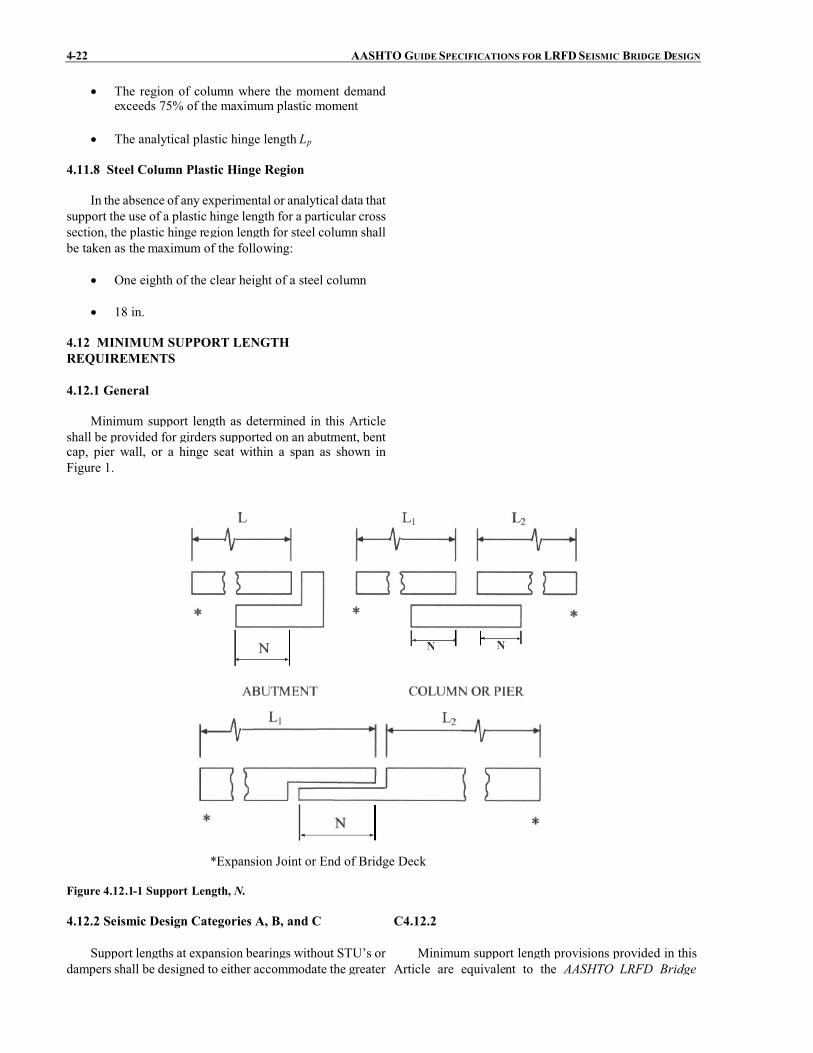
4-22 AASHTO GUIDE SPECIFICATIONS FOR LRFDSEISMIC BRIDGE DESIGN
� The region of column where the moment demandexceeds 75% of the maximum plastic moment
� The analytical plastic hinge length Lp
4.11.8 Steel Column Plastic Hinge Region
In the absence of any experimental or analytical data thatsupport the use of a plastic hinge length for a particular crosssection, the plastic hinge region length for steel column shallbe taken as the maximum of the following:
� One eighth of the clear height of a steel column
� 18 in.
4.12 MINIMUM SUPPORT LENGTHREQUIREMENTS
4.12.1 General
Minimum support length as determined in this Articleshall be provided for girders supported on an abutment, bentcap, pier wall, or a hinge seat within a span as shown inFigure 1.
*Expansion Joint or End of Bridge Deck
Figure 4.12.1-1 Support Length, N.
4.12.2 Seismic Design Categories A, B, and C C4.12.2
Support lengths at expansion bearings without STU’s ordampers shall be designed to either accommodate the greater
Minimum support length provisions provided in thisArticle are equivalent to the AASHTO LRFD Bridge

SECTION 4: ANALYSIS AND DESIGNREQUIREMENTS 4-23
of the maximum calculated displacement, except for bridgesin SDC A, or a percentage of the empirical support length, N,specified by Eq. 1. The percentage of N, applicable to eachSDC, shall be as specified in Table 1.
� �� �2000125.0108.002.08 SHLN ���� (4.12.2-1)
where:
N = minimum support length measured normal to thecenterline of bearing (in.)
L = length of the bridge deck to the adjacentexpansion joint, or to the end of the bridge deck;for hinges within a span, L shall be the sum of thedistances to either side of the hinge; for single-span bridges, L equals the length of the bridgedeck (ft.)
H = for abutments, average height of columnssupporting the bridge deck from the abutment tothe next expansion joint (ft.)
for columns and/or piers, column, or pier height(ft.)
for hinges within a span, average height of theadjacent two columns or piers (ft.)0.0 for single-span bridges (ft.)
S = angle of skew of support measured from a linenormal to span (°)
Table 4.12.2-1 PercentageN by SDC and effective peakground acceleration, AsSDC Effective peak ground
acceleration, AsPercent N
A 05.0 75�
A 05.0� 100
B All applicable 150
C All applicable 150
Design SpecificationsArticle 4.7.4.4.Support lengths are equal to the length of the overlap
between the girder and the seat as shown in Figure 1. Tosatisfy the minimum value forN in this Article, the overallseat width will be larger than N by an amount equal tomovements due to prestress shortening, creep, shrinkage,and thermal expansion/contraction. The minimum valuesfor N given in Eq. 1 includes an arbitrary allowance forcover concrete at the end of the girder and face of the seat.If above average cover is used at these locations, N shouldbe increased accordingly.
4.12.3 Seismic Design Category D C4.12.3
For SDC D, hinge seat or support length, N, shall beavailable to accommodate the relative longitudinal earthquakedisplacement demand at the supports or at the hinge within aspan between two frames and shall be determined as:
� � 24 1.65 (1 0.00025 ) 24eqN S� � � � � (4.12.3-1)
where:
�eq = seismic displacement demand of the long periodframe on one side of the expansion joint (in.). The
Support length requirements are based on the rigorousanalysis required for SDC D. As such, support lengthsdetermined for SDC D may be less than those determinedusing Article 4.12.2.

4-24 AASHTO GUIDE SPECIFICATIONS FOR LRFDSEISMIC BRIDGE DESIGN
elastic displacement demand shall be modifiedaccording to Articles 4.3.2 and 4.3.3.
S is defined above in Article 4.12.2.
The skew effect multiplier, (1+0.00025S2), may be setequal to 1 when the global model of the superstructure ismodeled to include the full width and the skew effects on thedisplacement demands at the outer face of the superstructure.
4.13 SUPPORT RESTRAINTS FOR SDC C AND D
Support restraints may be provided for longitudinallinkage at expansion joints within the space and at adjacentsections of simply supported superstructures. Their use isintended to achieve an enhanced performance of theexpansion joint and shall be approved and satisfy theOwner requirements. For continuous superstructuresspans, restrainers used to minimize displacements (i.e. tunethe out-of-phase displacement response) between theframes of a multi-frame system shall be consideredsecondary in reducing the out-of-phase motions at theexpansion joints between the frames. Restrainer units shallbe designed and detailed as described in the followingArticles.
4.13.1 Longitudinal Restrainers
Restrainers shall be designed using criteria prescribedby the owner.
Friction shall not be considered to be an effectiverestrainer.
If the restrainer shall be at a point where relativedisplacement of the sections of superstructure is designedto occur during seismic motions, sufficient slack shall beallowed in the restrainer so that the restrainer does not startto act until the design displacement is exceeded.
C4.13.1
Where a restrainer is to be provided at columns orpiers, the restrainer of each span may be attached to thecolumn or pier rather than to interconnecting adjacentspans.
In lieu of restrainers, Shock Transmission Units maybe used and designed for either the elastic force calculatedaccording to Article 4.2 or the maximum force effectsgenerated by inelastic hinging of the substructure asspecified in Article 4.11.2.
4.13.2 Simple Span Superstructures
An elastic response analysis or simple equivalentstatic analysis shall be considered adequate and reliable forthe design of restrainers for simple spans. An accelerationcoefficient not less than that specified in Article 4.5 shallbe used as a minimum.
4.13.3 Detailing Restrainers
� Restrainers shall be detailed to allow for easyinspection and replacement.
� Restrainer layout shall be symmetrical about thecenterline of the superstructure.
� Restrainer systems shall incorporate an adequategap for service conditions.
� Yield indicators may be used on cable restrainers

SECTION 4: ANALYSIS AND DESIGNREQUIREMENTS 4-25
to facilitate post earthquake investigations.
4.14 SUPERSTRUCTURE SHEAR KEYS C4.14
The design of the superstructure and the substructureshall take into consideration the anticipated load path. Forslender bents, shear keys on top of the bent cap mayfunction elastically at the design hazard level.
In lieu of experimental test data, the overstrengthshear key capacity, Vok , shall be taken as:
nok VV 2� (4.14-1)
where:
Vok = overstrength shear key capacity used inassessing the load path to adjacent capacity-protected members (kip)
Vn = nominal interface shear capacity of shear key asdefined in Article 5.8.4 of the AASHTO LRFDBridge Design Specifications using the expectedmaterial properties and interface surfaceconditions (kip)
For shear keys at intermediate hinges within a span,the designer shall assess the possibility of a shear keyfusing mechanism, which is highly dependent on out-of-phase frame movements. For bridges in SDC D whereshear keys are needed to achieve a reliable performance atthe design hazard level, (i.e., shear key element is part ofthe Earthquake Resistant System, ERS, see Article 3.3),nonlinear analysis should be conducted to derive thedistribution forces on shear keys affected by out-of-phasemotions.
Shear keys are typically designed to fuse at the designevent earthquake level of acceleration. Minimumrequirements herein are intended to keep the keys elastic ata lower more frequent earthquake event.

SECTION 5: ANALYTICAL MODELS AND PROCEDURES
TABLE OF CONTENTS
5-i
5.1 GENERAL........................................................................................................................................................ 5-15.1.1 Analysis of a Bridge ERS ....................................................................................................................... 5-15.1.2 Global Model.......................................................................................................................................... 5-2
5.2 ABUTMENTS.................................................................................................................................................. 5-35.2.1 General.................................................................................................................................................... 5-35.2.2 Wingwalls ............................................................................................................................................... 5-45.2.3 Longitudinal Direction............................................................................................................................ 5-4
5.2.3.1 Abutment Longitudinal Response for SDC B and C..................................................................... 5-55.2.3.2 Abutment Longitudinal Response for SDC D............................................................................... 5-55.2.3.3 Abutment Stiffness and Passive Pressure Estimate....................................................................... 5-6
5.2.4 Transverse Stiffness................................................................................................................................ 5-95.2.4.1 Abutment Transverse Response for SDC B and C ....................................................................... 5-105.2.4.2 Abutment Transverse Response for SDC D.................................................................................. 5-10
5.3 FOUNDATIONS .............................................................................................................................................. 5-105.3.1 General.................................................................................................................................................... 5-105.3.2 Spread Footing........................................................................................................................................ 5-115.3.3 Pile Foundations ..................................................................................................................................... 5-125.3.4 Drilled Shafts .......................................................................................................................................... 5-12
5.4 ANALYTICAL PROCEDURES...................................................................................................................... 5-125.4.1 General.................................................................................................................................................... 5-135.4.2 Procedure 1: Equivalent Static Analysis (ESA) ...................................................................................... 5-135.4.3 Procedure 2: Elastic Dynamic Analysis (EDA) ...................................................................................... 5-155.4.4 Procedure 3: Nonlinear Time History Method........................................................................................ 5-16
5.5 MATHEMATICAL MODELING USING EDA (PROCEDURE 2)................................................................ 5-175.5.1 General.................................................................................................................................................... 5-175.5.2 Superstructure ......................................................................................................................................... 5-175.5.3 Substructure ............................................................................................................................................ 5-18
5.6 EFFECTIVE SECTION PROPERTIES ........................................................................................................... 5-185.6.1 Effective Reinforced Concrete Section Properties for Seismic Analysis ................................................ 5-185.6.2 EcIeff and (GA)eff for Ductile Reinforced Concrete Members .................................................................. 5-185.6.3 Ieff for Box Girder Superstructures .......................................................................................................... 5-205.6.4 Ieff for Other Superstructure Types .......................................................................................................... 5-215.6.5 Effective Torsional Moment of Inertia .................................................................................................. 5-21
TO BE UPDATED BY AASHTO PUBLICATIONS


SECTION 5
ANALYTICAL MODELS AND PROCEDURES
5-1
5.1 GENERAL C5.1
A complete bridge system may be composed of asingle frame or a series of frames separated by expansionjoints and/or articulated construction joints. A bridge iscomposed of a superstructure and a supportingsubstructure.
Individual frame sections are supported on theirrespective substructures. Substructures consist of piers,single column or multiple column bents that are supportedon their respective foundations.
The determination of the seismic response of a bridgeincludes the development of an analytical model followedby the response analysis of the analytical model to predictthe resulting dynamic response for component design.Both the development of the analytical model and theselected analysis procedure are dependent on the seismichazard, selected seismic design strategy and the complexityof the bridge. There are various levels or degrees ofrefinement in the analytical model and analyticalprocedures that are available to the designer.
Seismic analysis encompasses a demand analysis anda displacement capacity verification. The objective of ademand analysis is to estimate the forces anddisplacements induced by the seismic excitation. Adisplacement capacity determination of piers and bents isrequired for SDC B, C, and D. The objective of adisplacement capacity determination is to determine thedisplacement of an individual pier when its deformationcapacity (that of the inelastic earthquake resisting element)is reached. The displacement capacity should be greaterthan the displacement demand. The accuracy of thedemand and capacity analyses depend on the assumptionof the model related to the geometry, boundary conditions,material properties, and energy-dissipation incorporated inthe model. It is the responsibility of the designer to assessthe reasonableness of a model in representing the behaviorof the structure at the level of forces and deformationsexpected for the seismic excitation.
The need for modeling of foundations and abutmentsdepends on the sensitivity of the structure to foundationflexibility and associated displacements. This in turndepends on whether the foundation is a spread footing, pilefooting with pile cap, a pile bent, or drilled shaft. Article5.3 defines the requirements for the foundation modelingin the seismic analysis.
When gross soil movement or liquefaction isdetermined to be possible, the model should represent thechange in support conditions and additional loads on thesubstructure associated with soil movement.
For structures whose response is sensitive to thesupport conditions, such as in a fixed-end arch, the modelof the foundation should account for the conditionspresent.
5.1.1 Analysis of a Bridge ERS
The entire bridge Earthquake Resistant System (ERS)for analysis purposes is referred to as the “global” model,whereas an individual bent or column is referred to as a“local” model. The term “global response” describes theoverall behavior of the bridge system including the effectsof adjacent components, subsystems, or boundaryconditions. The term “local response” referring to thebehavior of an individual component or subsystem beinganalyzed to determine, for example, its capacity using apushover analysis.
Development of both global models and local modelsare addressed in these Guide Specifications.
Individual bridge components shall have displacementcapacities greater than the displacement demands derivedfrom the “global” analysis.
The displacement demands of a bridge systemconsisting of multiple simple spans may be derived using

5-2 AASHTO GUIDE SPECIFICATIONS FOR LRFDSEISMIC BRIDGE DESIGN
the equivalent static analysis outlined in Article 5.4.2.Global analysis requirements as specified in Article 5.1.2need not to be applied in this case.
5.1.2 Global Model
A global model should be developed that capture theresponse of the entire bridge system. A global model forbridge systems with irregular geometry, in particularcurved bridges and skew bridges, should have the actualgeometry included. Also, multiple transverse expansionjoints, massive substructures components, and foundationssupported by soft soil can exhibit dynamic responsecharacteristics that should be included in the models astheir effect on the global response is not necessarilyintuitively obvious and may not be captured by a separatesubsystem analysis.
Linear elastic dynamic analysis shall as aminimumbeused for the global response analysis. There are however,some limitations in a linear elastic analysis approach whichshould be considered. The nonlinear response of yieldingcolumns, gapped expansion joints, earthquake restrainersand nonlinear soil properties can only be approximatedusing a linear elastic approach. Piece wise linear analysismay be used to approximate nonlinear response.Sensitivity studies using two bounding conditions may beused to approximate the non-linear effects.
For example, two global dynamic analyses should bedeveloped to approximate the nonlinear response of abridge with expansion joints because it possesses differentcharacteristics in tension and compression:
� In the tension model, the superstructure joints arepermitted to move independently of one anotherin the longitudinal direction. Appropriateelements connecting the joints may be used tomodel the effects of earthquake restrainers.
� In the compression model, all of the restrainerelements are inactivated and the superstructureelements are locked longitudinally to capturestructural response modes where the joints closeup, mobilizing the abutments when applicable.
The determination of whether both a tension modeland a compression model are required should be based onconsideration of the geometry of the structure. Structureswith appreciable superstructure curvature have a biasresponse to the outside of the curve and may requireadditional models, which combine the characteristicsidentified for the tension and compression models.
Long multi-frame bridges may be analyzed withmultiple elastic models. A single multi-frame model maynot be realistic since it cannot account for out-of-phasemovement among the frames.
Eachmulti-frame model may be limited to five framesplus a boundary frame or abutment on each end of the
C5.1.2
Depending on the chosen seismic analysis method,different types of approximations may be used formodeling the strength, stiffness, and energy-dissipationmechanisms. One-dimensional beam-column elements aresufficient for dynamic analysis of structures due toearthquake ground motion (referred to as “spine” modelsor “stick” models). For seismic analyses, grid or finite-element analyses are generally not necessary. They greatlyincrease the size of the model and complicate theunderstanding of the force and deformation distributionthrough the substructure because of the large number ofvibration modes.
The geometry of skew, horizontal curvature, and jointsize should be included in the model. However, two-dimensional models are adequate for bridges with skewangle less than 30° and a subtended angle of horizontalcurvature less than 20°. When skew is included in a three-dimensional model, the geometry and boundary conditionsat the abutments and bearings should be represented inorder to determine the forces and displacements at theselocations. Short columns or piers may be modeled with asingle element, but tall columns may have two or moreelements, particularly if they have significant mass (in thecase of concrete), or are modeled as framed substructures.
The use of compression and tension models isexpected to provide a reasonable bound on forces(compression model) and displacements (tension model).

SECTION 5: ANALYTICAL MODELS ANDPROCEDURES 5-3
model. Adjacent models shall overlap each other by atleast one useable frame, as shown in Figure 1. Amasslessspring should be attached to the dead end of the boundaryframes to represent the stiffness of the adjoining structure.The boundary frames provide some continuity betweenadjacent models but are considered redundant and theiranalytical results are ignored.
Tran. 1
Long. 2
Long. 1
Tran. 2
Boundary Frame 3
Boundary Frame 2
Tran. 3
Long. 3
Boundary Frame 2
Boundary Frame 1
Legend
Long.: Longitudinal Axis
Tran.: Transverse Axis
Bridge Expansion Joint
Abut
Abut
Model 1
Model 2
Model 3
Figure 5.1.2-1 Elastic Dynamic Analysis Modeling Technique.
5.2 ABUTMENTS
5.2.1 General
The model of the abutment shall reflect the expectedbehavior of the abutment with seismic loads applied ineach of the two horizontal directions. Resistance ofstructural components shall be represented by crackedsection properties where applicable when conducting anEquivalent Static Analysis or an Elastic DynamicAnalysis.
The resistance from passive pressure of the soilembankment at the abutment wall shall be represented by avalue for the secant stiffness consistent with the maximumdisplacement – according to Article 5.2.3. Depending onthe bridge configuration, one of two alternatives may bechosen by the designer:
C5.2.1
Article 5.2 provides requirements for the modeling ofabutments in the longitudinal and transverse directions.The iterative procedure with secant stiffness coefficientsdefined in those articles are included in the mathematicalmodel of the bridge to represent the resistance of theabutments in an elastic analysis.
The load-displacement behavior of the abutment maybe used in a static nonlinear analysis when the resistance ofthe abutment is included in the design of the bridge.
In general the connections between the superstructureand substructure should be designed for the maximumforces that could be developed. In the spirit of capacitydesign, this implies that the forces corresponding to the fullplastic mechanism (with yielding elements at their

5-4 AASHTO GUIDE SPECIFICATIONS FOR LRFDSEISMIC BRIDGE DESIGN
Earthquake Resisting System (ERS) withoutAbutment Contribution. ERS is designed to resistall seismic loads without any contribution fromabutments in either orthogonal direction.
Earthquake Resisting System (ERS) withAbutment Contribution. The ERS is designed withthe abutments as a key element of the ERS, in one orboth of the orthogonal directions. Abutments aredesigned and analyzed to sustain the DesignEarthquake displacements.
For the Displacement Capacity Verification, thestrength of each component in the abutment, including soil,shall be included.
overstrength condition) should be used to design theconnections. In cases where the full plastic mechanismmight not develop during the Design Earthquake, theelastic forces for this event are permitted. The minimumspecified requirements not withstanding, it is often goodpractice to design the connections to resist the higherforces corresponding to the full plastic mechanism. It isalso good practice to design for the best estimate of forcesthat might develop in cases such as pile bents with batteredpiles. In such bents the connections should be strongerthan the expected forces, and these forcesmaybe large andmay have large axial components. In such cases, theplastic mechanism may be governed by the pilegeotechnical strengths, rather than the pile structuralstrengths.
5.2.2 Wingwalls
The participation of abutment walls and wingwalls inthe overall dynamic response of bridge systems toearthquake loading and in providing resistance toseismically induced inertial loads may be considered in theseismic design of bridges. Damage to walls shall beconsidered an acceptable response during earthquakesconsidering No Collapse criteria. Abutment participationin the overall dynamic response of the bridge system shallreflect the structural configuration, the load-transfermechanism from the bridge to the abutment system, theeffective stiffness and force capacity of the wall-soilsystem, and the level of expected abutment damage. Thecapacity of the abutments to resist the bridge inertial loadshall be compatible with the structural design of theabutment wall, i.e., whether part of the wall will bedamaged by the design earthquake, as well as the soilresistance that can be reliably mobilized. The lateral loadcapacity of walls shall be evaluated based on an applicablepassive earth-pressure theory.
C5.2.2
A simplistic approach that may be used is to considerone wall 2/3 effective in acting against the abutment soilfill, while the second wall is considered 1/3 effective inacting against the outside sloped berm.
5.2.3 Longitudinal Direction
Under earthquake loading, the earth pressure action onabutment walls changes from a static condition to one ofgenerally two possible conditions; (1) the dynamic activepressure condition as the wall moves away from thebackfill, or (2) the passive pressure condition as the inertialload of the bridge pushes the wall to move inward towardthe backfill. The governing earth pressure conditiondepends on the magnitude of seismically inducedmovement of the abutment walls, the bridge superstructure,and the bridge/abutment configuration. For seat-typeabutments where the expansion joint is sufficiently large toaccommodate both the cyclic movement between theabutment wall and the bridge superstructure (i.e.,superstructure does not push against abutment wall), theseismically induced earth pressure on the abutment wallshall be considered to be the dynamic active pressurecondition. However, when the gap at the expansion joint is

SECTION 5: ANALYTICAL MODELS ANDPROCEDURES 5-5
not sufficient to accommodate the cyclic wall/bridgemovements, a transfer of forces will occur from thesuperstructure to the abutment wall. As a result, the activeearth pressure condition will not be valid and the earthpressure approaches a much larger passive pressure loadcondition behind the backwall, which is the main cause forabutment damage as witnessed in past earthquakes. Forstub or integral abutments, the abutment stiffness andcapacity under passive pressure loading are primary designconcerns.
5.2.3.1 Abutment Longitudinal Response for SDCB and C
Backwall reinforcement of seat-type abutments or thediaphragm of integral abutments designed primarily fornon-seismic load conditions shall be checked for theseismic load path and altered if deemed appropriate.
The provisions of Article 5.2.3.2 may be used for thedesign of abutments for bridges in SDC B or C.
C5.2.3.1
Abutments designed for bridges in SDC B or C areexpected to resist earthquake loads with minimal damage.For seat-type abutments, minimal abutment movementcould be expected under dynamic passive pressureconditions. However, bridge superstructure displacementdemands may be 4 in. or more and could potentiallyincrease the soil mobilization.
5.2.3.2 Abutment Longitudinal Response for SDCD
For SDCD, passive pressure resistance in soils behindintegral abutment walls and back walls for seat abutmentswill usually be mobilized due to the large longitudinalsuperstructure displacements associated with the inertialloads. Two alternatives may be considered by theDesigner:
� Case 1: Earthquake Resisting System (ERS)without Abutment Contribution. The bridgeERS shall be designed to resist all seismic loadswithout any contribution from abutments.Abutments may contribute to limitingdisplacement, providing additional capacity, andbetter performance that is not directly accountedfor in the analytical model. To ensure that thecolumns will be able to resist the lateral loads, azero stiffness and capacity at the abutmentsshould be assumed. In this case, an evaluation ofthe abutment which considers the implications ofsignificant displacements from seismicaccelerations shall be considered. Asappropriate, this evaluation should includeoverturning for abutments on spread footings orother structural configurations where overturningmay be a concern.
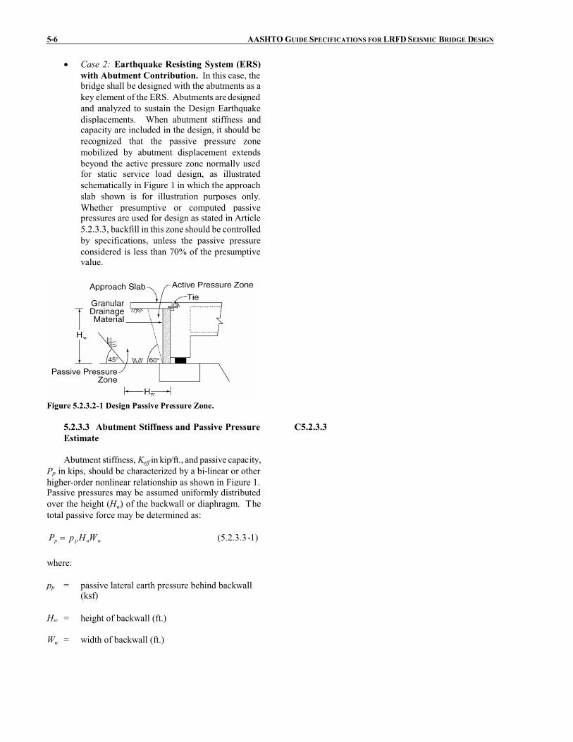
5-6 AASHTO GUIDE SPECIFICATIONS FOR LRFDSEISMIC BRIDGE DESIGN
� Case 2: Earthquake Resisting System (ERS)with Abutment Contribution. In this case, thebridge shall be designed with the abutments as akey element of the ERS. Abutments are designedand analyzed to sustain the Design Earthquakedisplacements. When abutment stiffness andcapacity are included in the design, it should berecognized that the passive pressure zonemobilized by abutment displacement extendsbeyond the active pressure zone normally usedfor static service load design, as illustratedschematically in Figure 1 in which the approachslab shown is for illustration purposes only.Whether presumptive or computed passivepressures are used for design as stated in Article5.2.3.3, backfill in this zone should be controlledby specifications, unless the passive pressureconsidered is less than 70% of the presumptivevalue.
Figure 5.2.3.2-1 Design Passive Pressure Zone.
5.2.3.3 Abutment Stiffness and Passive PressureEstimate
Abutment stiffness, Keff in kip/ft., and passive capacity,Pp in kips, should be characterized by a bi-linear or otherhigher-order nonlinear relationship as shown in Figure 1.Passive pressures may be assumed uniformly distributedover the height (Hw) of the backwall or diaphragm. Thetotal passive force may be determined as:
wwpp WHpP � (5.2.3.3-1)
where:
pp = passive lateral earth pressure behind backwall(ksf)
Hw = height of backwall (ft.)
Ww = width of backwall (ft.)
C5.2.3.3
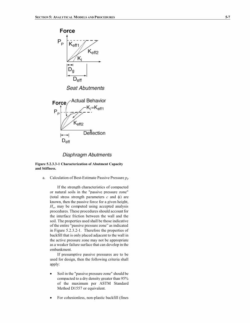
SECTION 5: ANALYTICAL MODELS ANDPROCEDURES 5-7
Figure 5.2.3.3-1 Characterization of Abutment Capacityand Stiffness.
a. Calculation of Best-Estimate Passive Pressure pp
If the strength characteristics of compactedor natural soils in the "passive pressure zone"(total stress strength parameters c and �) areknown, then the passive force for a given height,Hw, may be computed using accepted analysisprocedures. These procedures should account forthe interface friction between the wall and thesoil. The properties used shall be those indicativeof the entire “passive pressure zone” as indicatedin Figure 5.2.3.2-1. Therefore the properties ofbackfill that is only placed adjacent to the wall inthe active pressure zone may not be appropriateas a weaker failure surface that can develop in theembankment.
If presumptive passive pressures are to beused for design, then the following criteria shallapply:
� Soil in the "passive pressure zone" should becompacted to a dry density greater than 95%of the maximum per ASTM StandardMethod D1557 or equivalent.
� For cohesionless, non-plastic backfill (fines

5-8 AASHTO GUIDE SPECIFICATIONS FOR LRFDSEISMIC BRIDGE DESIGN
content less than 30%), the passive pressurepp may be assumed equal to 2Hw/3 ksf perfoot of wall length.
� For cohesive backfill (clay fraction > 15%),the passive pressure pp may be assumedequal to 5 ksf provided the estimatedundrained shear strength is greater than 4ksf.
The presumptive values given above shall beconsidered applicable for use in the “PermissibleEarthquake Resisting Elements that RequireOwner’s Approval”, as defined in Article 3.3. Ifthe design is based upon presumptive resistancesthat are not greater than 70% of the values listedabove, then the structure may be classified in the“Permissible Earthquake Resisting Elements”.
b. Calculation of Soil Stiffness
An equivalent linear secant stiffness, Keff inkip/ft., is required for analyses. For integral ordiaphragm type abutments, an initial secantstiffness (Figure 1) may be determined asfollows:
� �ww
peff HF
PK �1 (5.2.3.3-2)
where:
Pp = passive lateral earth pressure capacity(kip)
Hw = height of backwall (ft.)
Fw = factor taken as between 0.01 to 0.05 forsoils ranging from dense sand tocompacted clays
If computed abutment forces exceed the soilcapacity, the stiffness should be softenediteratively (Keff1 to Keff2) until abutmentdisplacements are consistent (within 30%) withthe assumed stiffness. For seat type abutmentsthe expansion gap should be included in theinitial estimate of the secant stiffness. Asspecified in Eq. 3:
� �gww
peff DHF
PK
��1 (5.2.3.3-3)
where:
Dg = width of gap between backwall and
Guidance on the value of Fw to use for a particularbridge may be found in Table C3.11.1-1 of the AASHTOLRFD Bridge Design Specifications. The table presentsvalues of Fw for dense sand, medium dense sand, loosesand, compacted silt, compacted lean clay, and compactedfat clay. If the influence of passive pressure extendsbeyond one particular soil type at an abutment, averaged orweighted average values for Fw may be used at theengineer’s discretion.
SECTION 5: ANALYTICAL MODELS ANDPROCEDURES 5-9
superstructure (ft.)
For SDC D, where pushover analyses areconducted, values of Pp and the initial estimate ofKeff1should be used to define a bilinear load-displacementbehavior of the abutment for the capacity assessment.
5.2.4 Transverse Stiffness C5.2.4
Two alternatives may be considered by the designer:
� Case 1: Earthquake Resisting System (ERS)without Abutment Contribution. The bridgeERS shall be designed to resist all seismic loadswithout any contribution from abutments.Concrete Shear Keys shall be consideredsacrificial where they are designed for lateralloads lower than the Design Earthquake loads. Aminimum level of design for shear keyscorresponds to lateral loads not includingearthquake loads. If sacrificial concrete shearkeys are used to protect the piles, the bridge shallbe analyzed and designed according to Articles5.2.4.1 and 5.2.4.2 as applicable. If a fuse isused, then the effects of internal forceredistribution resulting from fusing shall be takeninto account in the design of the bridge.Limitations on the use of fusing (hinging orfailure of a bridge component along theearthquake load path) for SDC C or D are listedbelow.
� Case 2: Earthquake Resisting System (ERS)with Abutment Contribution. The bridge shalldesigned with the abutments as a key element ofthe ERS. Shear keys at the abutment shall bedesigned and analyzed to sustain the lesser of theDesign Earthquake forces or sliding frictionforces of spread footings. Pile supportedfoundations shall be designed to sustain theDesign Earthquake displacements. Inelasticbehavior of piles at the abutment shall beconsidered to be acceptable.
In the context of these provisions, elastic resistanceshall be taken to include the use of:
� elastomeric,
� sliding, or isolation bearings designed toaccommodate the design displacements,
� soil frictional resistance acting against the base ofa spread footing-supported abutment,
� pile resistance provided by piles acting in theirelastic range, or passive resistance of soil acting
For both Cases 1 and 2, abutment pile foundationsmay be considered adequate to carry the vertical deadloads following the design event for the no collapsecriteria.
5-10 AASHTO GUIDE SPECIFICATIONS FOR LRFDSEISMIC BRIDGE DESIGN
at displacements less that 2% of the wall height.
Likewise, fusing includes:
� breakaway elements, such as isolation bearingswith a relatively high yield force;
� shear keys;
� yielding elements, such as wingwalls yielding attheir junction with the abutment backwall;
� elastomeric bearings whose connections havefailed and upon which the superstructure issliding;
� spread footings that are proportioned to slide; or
� piles that develop a complete plastic mechanism.
The stiffness of the abutment foundation undertransverse loading may be calculated based on theprocedures given in Article 5.3. Where fusing elementsare used, allowance shall be made for the reducedequivalent stiffness of the abutment after fusing occurs.
5.2.4.1 Abutment Transverse Response for SDCBand C
Shear keys shall be designed to resist a horizontalseismic force not less than the effective peak groundacceleration coefficient, As, as specified in Article 3.4,times the tributary permanent load.
Fusing is not expected for SDC B or C; however, ifdeemed necessary, shall be checked using the procedureapplicable to SDC D according to Article 5.2.4.2 takinginto account the overstrength effects of shear keysaccording to Article 4.14.
C5.2.4.1
For bridges in these categories, elastic resistance maybe achievable.
5.2.4.2 Abutment Transverse Response for SDCD
For structures in this category, either elastic resistanceor fusing shall be used to accommodate transverseabutment loading. The elastic forces used for transverseabutment design shall be determined from an elasticdemand analysis of the structure.
Where a shear key fusing mechanism is used for pile-supported abutments, the combined overstrength capacityof the shear keys shall be less than the combined plasticshear capacity of the piles. Soil friction and passive earthpressure shall not be included in the transverse abutmentresistance of pile-supported abutments.
For concrete shear keys that are not intended to fuse,the design should consider the unequal forces that maydevelop in each shear key.
Recessed or hidden shear keys are difficult to inspectand repair and should be avoided if possible.
C5.2.4.2
Shear keys are typically classified as either:
� Interior – multiple shear keys placedbetween adjacent girders such that eachindividual shear key accommodates someportion of the total load
� Exterior – one shear key on each exteriorface of the superstructure such that only oneshear key is used to accommodate the totalload in each direction
Shear keys are used at abutments to provide transverserestraint for bridge superstructures under seismic and non-seismic loads. For seismic design, sacrificial shear keyscan serve as structural fuses to limit the demand and

SECTION 5: ANALYTICAL MODELS ANDPROCEDURES 5-11
For pile-supported abutment foundations, the stiffnesscontribution of standard size piles (i.e., less than or equalto 18 in.) shall be ignored if the abutment displacement isgreater than 4 in. unless a displacement capacity analysisof the piles is performed and the piles are shown to becapable of accommodating the demands.
thereby control the damage in the abutments andsupporting piles.
Variations in shear key stiffness, shear key-to-superstructure gap size, and skew angle result in theunequal loading of interior shear keys. Unequal loading isfurther complicated for structures with intermediate piersof unequal stiffness. Consequently, the accuratedetermination of individual shear key design forces isdifficult.
Due to the complications of accurately determiningthe design forces for interior shear keys, the use of exteriorshear keys is recommended. Furthermore, exterior shearkeys are usually recommended for new constructionbecause they are easier to inspect and repair.
For interior shear keys that are intended to resist theelastic seismic forces, unequal loading should beconsidered in the design. For sacrificial shear keys,unequal loading may be of less concern because the shearkeys are expected to fuse prior to the formation of plasticresponse in the piles. Thus, the unequal loading of interiorshear keys may result in an “unzipping” response thatwould effectively reduce the abutment demand.Nonetheless, the combined overstrength capacity of allinterior shear keys should be used when designing theabutment.
5.3 FOUNDATIONS
5.3.1 General
The FoundationModelingMethods(FMM) defined inTable 1 should be used as appropriate. The requirementsfor estimating foundation springs for spread footings, pilefoundations, and the depth to fixity for drilled shafts shallbe as specified in Articles 5.3.2, 5.3.3 and 5.3.4,respectively. For a foundation which is considered asrigid, the mass of the foundation should be ignored in theanalytical model. The Engineer shall assess the merits ofincluding the foundation mass in the analytical modelwhere appropriate taking into account therecommendations in this Article.
The required foundationmodelingmethod depends onthe Seismic Design Category (SDC).
Foundation Modeling Method I is required as aminimum for SDC B & C provided foundation is locatedin Site Class A, B, C, or D. Otherwise, FoundationModeling Method II is required.
Foundation Modeling Method II is required for SDCD.
The foundation models in the multi-mode dynamicanalysis and Displacement Capacity Verification shall beconsistent and representative of the footing behavior.Foundation Modeling Method II is required in theDisplacement Capacity Verification (“pushover”) analysisif it is used in the multi-mode dynamic analysis fordisplacement demand.
For sites identified as susceptible to liquefaction or
C5.3.1
Awide range of methods formodeling foundations forseismic analysis is available. Generally a refined model isunnecessary for seismic analysis. For many cases theassumption of a rigid foundation is adequate. Flexibility ofa pile bent or shaft can be estimated using an assumedpoint-of-fixity associated with the stiffness estimate of thepile (or shaft) and the soil. Spread footings and piles canbe modeled with rotational and translational springs.
The requirement for including soil springs forFoundation Modeling Method II depends on thecontribution of the foundation to the elastic displacementof the pier. More flexible spread and pile footings shouldbe modeled and included in the seismic analysis.
If foundation springs are included in the multi-modedynamic analysis, they should be included in the pushoveranalysis so the two models are consistent for thedisplacement comparison.
For most spread footings and piles with pile caps asecant stiffness for the soil springs is adequate. Bi-linearsoil springs are used for the pushover analysis.
For pile bents and drilled shafts, an estimated depth tofixity is generally adequate for representing the relativeflexibility of the soil and pile or shaft. Soil springs withsecant stiffness may be used to provide a betterrepresentation based onP-y curves for the footing and soil.Bi-linear springs may be used in the pushover analysis ifthere is particular concern with depth of the plastic hinge

5-12 AASHTO GUIDE SPECIFICATIONS FOR LRFDSEISMIC BRIDGE DESIGN
lateral spread, the ERS global model shall consider thenon-liquefied and liquefied conditions using theprocedures specified in Article 6.8.
and effective depth of fixity.
Table 5.3.1-1 Definition of Foundation Modeling Method (FMM).Foundation Type Modeling Method I Modeling Method II
Spread Footing RigidRigid for Site Classes A and B. For other soil types,foundation springs required if footing flexibilitycontributes more than 20% to pier displacement.
Pile Footing withPile Cap Rigid Foundation springs required if footing flexibility
contributes more than 20% to pier displacement.Pile Bent/Drilled
ShaftEstimated depth to
fixityEstimated depth to fixity or soil-springs based on P-
y curves.
5.3.2 Spread Footing
Where it is necessary to represent foundationflexibility, spring constants shall be developed for themodeling of spread footings.
The shear modulus (G) used to compute stiffnessvalues should be determined by adjusting the low-strainshear modulus (Gmax) for the level of shearing strain usingstrain adjustment factors (G/Gmax) which are less than one(1.0). Strain adjustment factors for SDC D should be lessthan those for SDC B or C.
Values of Gmax shall be determined by seismicmethods (e.g., crosshole, downhole, or SASW), bylaboratory testing methods (e.g., resonant column withadjustments for time), or by empirical equations (Kramer,1996). The uncertainty in determination of Gmax shall beconsidered when establishing strain adjustment factors.
No special computations are required to determine thegeometric or radiation damping of the foundation system.Five percent system damping shall be used for design,unless special studies are performed and approved by theowner.
Moment-rotation and shear force-displacement shallbe represented by a bi-linear relationship. The rotationalspring constant of the spread footing shall be taken as theinitial slope of the bi-linear moment-rotation curve.
The maximum resisting force (i.e., plastic capacity) onthe force-deformation curve shall be defined for the best-estimate case of geotechnical properties.
C5.3.2
Procedures given in the FEMA273Guidelines for theSeismicRehabilitation of Buildings (ATC/BSSC, 1997) areacceptable for estimating spring constants. Thesecomputational methods are appropriate for sites that do notliquefy or lose strength during earthquake loading.
Uplift or rocking analysis for spread footings may beconsidered with the owner’s approval. See Appendix A.

SECTION 5: ANALYTICAL MODELS ANDPROCEDURES 5-13
5.3.3 Pile Foundations
The design of pile foundations shall be based oncolumn loads determined by capacity design principles(Article 4.11) or elastic seismic forces, whichever issmaller for SDCB and based on capacity design principlesonly for SDCC or D. Both the structural and geotechnicalelements of the foundation shall be designed accordingly.
Foundation flexibility shall be incorporated intodesign for SDC D according to Article 5.3.1.
The nonlinear properties of the piles shall beconsidered in evaluating the lateral response of the piles tolateral loads during a seismic event.
Liquefaction shall be considered using proceduresspecified in Article 6.8 for SDCDwhere applicable duringthe development of spring constants and capacity values.
C5.3.3
A group reduction factor established in thegeotechnical report should be considered in the analysis.Analyzing the structure with andwithout consideration of agroup reduction factor should also be considered since theoverall response of the structure for these two cases mayvary significantly.
5.3.4 Drilled Shafts
The flexibility of the drilled shaft shall be representedusing either the estimated depth of fixity or soil springs ina lateral pile analysis. Procedures identified in Article5.3.3 including those for liquefaction, may be used exceptthat group reduction factors are typically considered onlyin the transverse direction of a multi-shaft bent.
C5.3.4
Section properties of drilled shafts should beconsistent with the deformation caused by the seismicloading. In many cases it is necessary to use the crackedsection modulus in the evaluation of lateral load-displacement relationships. In the absence of detailedinformation regarding reinforcing steel and applied load,an equivalent cracked section can be estimated by reducingthe stiffness of the uncracked section by half. In generalthe cracked section is function of the reinforcement ratioand axial load, but it often adequate to assume as one-halfof the uncracked section.
5.4 ANALYTICAL PROCEDURES
5.4.1 General
The objective of seismic analysis is to assessdisplacement demands of a bridge and its individualcomponents. Equivalent static analysis and linear elasticdynamic analysis are the appropriate analytical tools forestimating the displacement demands for normal bridges.Inelastic static analysis “Pushover Analysis” is theappropriate analytical tool used to establish thedisplacement capacities for normal bridges assigned toSDC D.
Nonlinear Time History analysis should be used forcritical or essential bridges as defined in Article 4.2.2 andin some cases for Normal Bridges in SDCD using devicesfor isolation or energy dissipation. In this type of analysis,component capacities are characterized in themathematical model used for the seismic response analysis.The procedures mentioned above are described in moredetail below in Article 5.4.4.
C5.4.1
For bridges with a regular configuration, a single-degree-of-freedom model is sufficiently accurate torepresent the seismic response. For these types of bridges,the equivalent static analysis (Procedure 1) may be used toestablish displacement demands.
For structures that do not satisfy the requirements ofregularity for an elastic response spectrum analysis,Procedure 2, should be used to determine the displacementdemands
5.4.2 Procedure 1: Equivalent Static Analysis (ESA)
ESA may be used to estimate displacement demandsfor structures where a more sophisticated dynamic analysis
C5.4.2
The equivalent static analysis is suitable for short tomedium span structures with regular configuration. Long

5-14 AASHTO GUIDE SPECIFICATIONS FOR LRFDSEISMIC BRIDGE DESIGN
will not provide additional insight into behavior. ESAshould be considered to be best suited for structures orindividual frames with well balanced spans and uniformlydistributed stiffness where the response can be captured bya predominant translational mode of vibration.
Both the Uniform Load Method and the Single ModeSpectral Analysis Method shall be considered acceptableequivalent static analysis procedures.
The Uniform Load Method shall be based on thefundamental mode of vibration in either the longitudinal ortransverse direction. The period of this mode of vibrationshall be taken as that of an equivalent single mass-springoscillator. The stiffness of this equivalent spring shall becalculated using the maximum displacement that occurswhen an arbitrary uniform lateral load is applied to thebridge.
The Single-Mode Spectral Analysis Method shall bebased on the fundamental mode of vibration in either thelongitudinal or transverse direction. This mode shapemaybe found by applying a uniform horizontal load to thestructure and calculating the corresponding deformedshape. The natural period may be calculated by equatingthe maximum potential and kinetic energies associatedwith the fundamental mode shape. The procedure forusing the Single-Mode Spectral AnalysisMethod found inthe AASHTO LRFD Bridge Design Specifications Article4.7.4.3.2b may be used.
bridges, or those with significant skew or horizontalcurvature, have dynamic characteristics that should beassessed in a multi-mode dynamic analysis.
The UniformLoadMethod, described in the followingsteps, may be used for both transverse and longitudinalearthquake motions. It is essentially an equivalent staticmethod of analysis that uses a uniform lateral load toapproximate the effect of seismic loads. The method issuitable for regular bridges that respond principally in theirfundamental mode of vibration.
Whereas displacements are calculatedwith reasonableaccuracy, the method can overestimate the transverseshears at the abutments by up to 100%. Consequently, thecolumns may have inadequate lateral strength because ofthe overestimate of abutment forces. The Single-ModeSpectral Analysis Method or a multi-mode dynamicanalysis is recommended to avoid unrealistic distributionsof seismic forces.
The steps in the uniform load method are as follows:
1. Calculate the static displacements vs(x) due to anassumed uniform load po, as shown in Figure C1.The uniform loadingpo is applied over the lengthof the bridge; it has dimension of force/unitlength and may be arbitrarily set equal to 1.0.The static displacement vs(x) has the dimension oflength.
2. Calculate the bridge lateral stiffness,K, and totalweight, W, from the following expressions:
max,s
o
vLpK � (C5.4.2-1)
!�L
dxxwW0
)( (C5.4.2-2)
where:
po = uniform lateral load applied overthe length of the structure (kip/ft.or kip/in.)
L = total length of the structure (ft. orin.)
vs,max = maximum lateral displacementdue to uniform load po (ft. or in.)
w(x) = nominal dead load of the bridgesuperstructure and tributarysubstructure (kip/ft. or kip/in.)
W = total weight of structure (kip)
K = effective lateral bridge stiffness(kip/ft. or kip/in.)

SECTION 5: ANALYTICAL MODELS ANDPROCEDURES 5-15
The weight should take into account structuralelements and other relevant loads including, butnot limited to, pier caps, abutments, columns, andfootings. Other loads, such as live loads, may beincluded.
3. Calculate the period of the bridge, Tm, using theexpression:
KgWTm "� 2 (C5.4.2-3)
where:
g = acceleration due to gravity (ft./sec.2 orin./sec.2)
4. Calculate the equivalent static earthquake loadingpe from the expression:
LWSp a
e � (C5.4.2-4)
where:
Sa = design response spectral accelerationcoefficient determined in accordancewith Article 3.4.1 for T=Tm
pe = equivalent uniform static lateral seismicload per unit length of bridge applied torepresent the primarymode of vibration(kip/ft. or kip/in.)
5. Calculate the displacements and member forcesfor use in design either by applying pe to thestructure and performing a second static analysisor by scaling the results of the first step above bythe ratio pe /po.
The configuration requirements for Equivalent StaticAnalysis (Procedure 1) analysis restrict application toindividual frames or units that can be reasonably assumedto respond as a single-degree-of-freedom system in thetransverse and longitudinal directions. When abutments donot resist significant seismic forces, the superstructurewillrespond as a rigid-body mass. The lateral-load-resistingpiers or bents should be uniform in strength and stiffness tojustify the assumption of independent transitional responsein the longitudinal and transverse directions.

5-16 AASHTO GUIDE SPECIFICATIONS FOR LRFDSEISMIC BRIDGE DESIGN
Figure C5.4.2-1 Bridge Deck Subjected to AssumedTransverse and Longitudinal Loading.
5.4.3 Procedure 2: Elastic Dynamic Analysis (EDA)
EDA shall be used to estimate the displacementdemands for structures where ESA does not provide anadequate level of sophistication to estimate the dynamicbehavior. A linear elastic multi-modal spectral analysisutilizing the appropriate response spectrum (i.e., 5%damping) shall be performed. The number of degrees offreedom and the number of modes considered in theanalysis shall be sufficient to capture at least 90% massparticipation in both the longitudinal and transversedirections. A minimum of three elements per flexiblecolumn and four elements per span shall be used in thelinear elastic model.
The engineer should recognize that forces generatedby linear elastic analysis could vary, depending on thedegree of non-linear behavior, from the actual forcedemands on the structure. Displacements are not assensitive to the nonlinearities and may be considered goodapproximations. Sources of nonlinear response that are notcaptured by EDA include the effects of the surroundingsoil, yielding of structural components, opening andclosing of expansion joints, and nonlinear restrainer andabutment behavior. EDAmodal results shall be combinedusing the complete quadratic combination (CQC) method.
For multi-frame analysis it is recommended to includea minimum of two boundary frames or one frame and anabutment beyond the frame under consideration. (SeeArticle 5.1.2).
C5.4.3
The model for an elastic response spectrumanalysis islinear, and as such it does not represent the inelasticbehavior of earthquake-resisting elements under strongground motion. However, with the proper representationof the inelastic elements and interpretation of responses, anelastic analysis provides reasonable estimates of seismicdisplacement demands. The model should be based oncracked section properties for concrete components, andon secant stiffness coefficients for the foundations,abutments, and seismic isolation components. Modelingshould be consistent with the expected levels ofdeformation of all components. The displacements at thecenter of mass, generally the superstructure, can be used toestimate the displacement demand of the structureincluding the effect of inelastic behavior in the earthquake-resisting elements.
For SDC D, a displacement capacity evaluation isrequired. The displacement capacity evaluation involvesdetermining the displacement at which the first componentreaches its inelastic deformation capacity. All non-ductilecomponents should be designed using capacity designprinciples to avoid brittle failure. For simple piers or bents,the displacement capacity can be evaluated by simplecalculations using the geometry of displaced shapes, andforces and deformations at the plastic hinges. For morecomplicated piers or bents, particularly when foundationsand abutments are included in the model, a nonlinear static(“pushover”) analysis may be used to evaluate thedisplacement capacity. It is recommended that the

SECTION 5: ANALYTICAL MODELS ANDPROCEDURES 5-17
nonlinear static analysis continue beyond the displacementat which the first component reaches its inelasticdeformation capacity in order to assess the behaviorbeyond the displacement capacity and obtain a betterunderstanding of the limit states.
The displacement capacity is compared to thedisplacement demand determined froman elastic response-spectrum analysis.
Vibration modes are convenient representations ofdynamic response for response spectrumanalysis. Enoughmodes should be included to provide sufficientparticipation for bending moments in columns, or othercomponents with inelastic deformation. Dynamic analysisprograms, however, usually compute participation factorsonly for base shear, often expressed as a percentage oftotal mass. For regular bridges the guideline of including90% of the modal mass for horizontal componentsgenerally provides a sufficient number of modes foraccurate estimate of forces in lateral-load-resistingcomponents. For irregular bridges, or large models ofmultiple-frame bridges, the participating mass may notindicate the accuracy for forces in specific components. Itis for this reason that the models of long bridges arelimited to five frames.
The response spectrum in Article 3.4.1 is based on 5%damping. For bridges with seismic isolation the additionaldamping from the seismic isolator units applies only to theisolated vibration modes. Other vibration modes have 5%damping.
5.4.4 Procedure 3: Nonlinear Time History Method
The time histories of input acceleration used todescribe the earthquake loads shall be selected inconsultation with the Owner or Owner’s representative.Time-History Analysis shall be performed with no fewerthan three data sets (two horizontal components and onevertical component) of appropriate ground motion timehistories selected from not less than three recorded orsynthetic events. Appropriate time histories shall representmagnitude, fault distances and source mechanisms that areconsistent with those that control the design earthquakeground motion. Each time history shall be modified to beresponse-spectrum compatible using the time-domainprocedure.
Where three time history data sets are used in theanalysis of a structure, the maximum value of eachresponse parameter (e.g., force in a member, displacementat a specific level) shall be used to determine designacceptability. Where seven or more time history data setsare employed, the average value of each responseparameter may be used to determine design acceptability.The sensitivity of the numerical solution to the size of thetime step used for the analysis shall be determined. Asensitivity study shall also be carried out to investigate theeffects of variations in assumed material properties.
C5.4.4
A nonlinear dynamic analysis is a morecomprehensive analysis method because the effect ofinelastic behavior is included in the demand analysis.Depending on the mathematical model, the deformationcapacity of the inelastic elements may or may not beincluded in the dynamic response analysis. A nonlineardynamic response analysis requires a suite of time-histories(Article 3.4.4) of earthquake ground motion that isrepresentative of the hazard and conditions at the site.Because of the complexity involved with nonlineardynamic analysis, it is best used in conjunction with SDCD or in a case where seismic isolation is included in thedesign strategy.
Seismically isolated structures with long periods orlarge damping ratios require a nonlinear dynamic analysisbecause the analysis procedures using an effective stiffnessand damping may not properly represent the effect ofisolation units on the response of the structure. The modelfor nonlinear analysis should represent the hystereticrelationships for the isolator units.

5-18 AASHTO GUIDE SPECIFICATIONS FOR LRFDSEISMIC BRIDGE DESIGN
5.5 MATHEMATICAL MODELING USING EDA(PROCEDURE 2)
5.5.1 General
The bridge should be modeled as a three-dimensionalspace frame with joints and nodes selected to realisticallymodel the stiffness and inertia effects of the structure.
The mass should take into account structural elementsand other relevant loads including, but not limited to, piercaps, abutments, columns and footings. Other loads suchas live loads may be included.
C5.5.1
For elastic analysis methods, there is a significantapproximation in representing the force-deformationrelationship of inelastic structural elements by a singlelinearized stiffness. For inelastic columns or other inelasticearthquake-resisting elements, the common practice is touse an elastic stiffness for steel elements and a crackedstiffness for reinforced concrete elements. However, thestiffness of seismic isolator units, abutments, andfoundation soils are represented by a secant stiffnessconsistent with the maximum deformation. The designershould consider the displacements from an elastic analysisto verify that they are consistent with the inelastic behaviorof the earthquake-resisting elements.
The objective of the nonlinear displacement capacityverification is to determine the displacement at which theinelastic components reach their deformation capacity.The deformation capacity is the sum of elastic and plasticdeformations. The plastic deformation is expressed interms of the rotation of the plastic hinges. A nonlinearanalysis using expected strengths of the components giveslarger plastic deformations than an analysis includingoverstrength. Hence, it is appropriate to use the expectedstrength of the components when estimating thedisplacement capacity.
5.5.2 Superstructure
The superstructure shall, as aminimum, bemodeled asa series of space frame members with nodes at such pointsas the span quarter points in addition to joints at the endsof each span. Discontinuities should be included in thesuperstructure at the expansion joints and abutments. Careshould be taken to distribute properly the lumped massinertia effects at these locations. The effect of earthquakerestrainers at expansion joints may be approximated bysuperimposing one or more linearly elastic membershaving the stiffness properties of the engaged restrainerunits.
C5.5.2
For a spine or stick model of the superstructure, thestiffness is represented by equivalent section properties foraxial deformation, flexure about two axes, torsion, andpossibly shear deformation in two directions. Thecalculation of the section stiffness should representreasonable assumptions about the three-dimensional flowof forces in the superstructure, including compositebehavior.
5.5.3 Substructure
The intermediate columns or piers should also bemodeled as space framemembers. Long, flexible columnsshould be modeled with intermediate nodes at the thirdpoints in addition to the joints at the ends of the columns.The model should consider the eccentricity of the columnswith respect to the superstructure. Foundation conditionsat the base of the columns and at the abutments may bemodeled using equivalent linear spring coefficients.

SECTION 5: ANALYTICAL MODELS ANDPROCEDURES 5-19
5.6 EFFECTIVE SECTION PROPERTIES
5.6.1 Effective Reinforced Concrete Section Propertiesfor Seismic Analysis
Since elastic analysis assumes a linear relationshipbetween stiffness and strength, analysis of concretemembers shall consider that they display nonlinearresponse before reaching their idealized yield limit state.
Section properties, flexural stiffness, EcIeff, shearstiffness parameter (GA)eff, and torsional stiffness GcJeff,shall reflect the cracking that occurs before the yield limitstate is reached. The effective moments of inertia, Ieff andJeff shall be used to obtain realistic values for thestructure’s period and the seismic demands generated fromESA and EDA analyses.
5.6.2 EcIeff and (GA)eff for Ductile ReinforcedConcreteMembers
The effective moment of inertia Ieff should be usedwhen modeling ductile elements. Ieff may be estimated byFigure 1 or the slope of the M-� curve between the originand the point designating the first reinforcing bar yieldshall be taken as:

5-20 AASHTO GUIDE SPECIFICATIONS FOR LRFDSEISMIC BRIDGE DESIGN
(a) Circular Sections.
(a) Rectangular Sections.
Figure 5.6.2-1 Effective Flexural Stiffness of Cracked Reinforced Concrete Sections.
y
yeffc
MIE
�� (5.6.2-1)
where:

SECTION 5: ANALYTICAL MODELS ANDPROCEDURES 5-21
My = moment capacity of section at first yield of thereinforcing steel (kip-in.)
�y = curvature of section at first yield of thereinforcing steel including the effects of theunfactored axial dead load (1/in.)
Ec = modulus of elasticity of concrete (ksi)
Ieff = effective moment of inertia of the section basedupon cracked concrete and first yield of thereinforcing steel (in.4)
Typically the unfactored axial gravity load shall beused when determining the effective properties.
The M-� analysis parameters shall be taken asspecified in Articles 8.4 and 8.5.
For pier walls in the strong direction, the shearstiffness parameter (GA)eff may be determined as follows:
� �g
effewceff II
AGGA � (5.6.2-2)
where:
(GA)eff = effective shear stiffness parameter of the pierwall (kip)
Gc = shear modulus of concrete (ksi)
Aew = cross sectional area of pier wall (in.2)
Ig = gross moment of inertia taken about theweakaxis of the reinforced concrete cross section(in.4)
Ieff = effective moment of inertia taken about theweak axis of the reinforced concrete crosssection calculated from Eq. 1 or Figure 1(in.4)
5.6.3 Ieff for Box Girder Superstructures
The determination of Ieff for box girder superstructuresshould include consideration of the following:
� Ieff in box girder superstructures is dependent onthe extent of cracking and the effect of thecracking on the element’s stiffness.
� Ieff for reinforced concrete box girder sectionsmay be estimated between 0.5Ig and 0.75Ig. Thelower bound represents lightly reinforced sectionsand the upper bound represents heavilyreinforced sections.

5-22 AASHTO GUIDE SPECIFICATIONS FOR LRFDSEISMIC BRIDGE DESIGN
� The location of the centroid of the prestressingsteel and the direction of bending have asignificant impact on how cracking affects thestiffness of prestressed members. Multi-modalelastic analysis is incapable of capturing thevariations in stiffness caused bymoment reversal.Therefore, no stiffness reduction is recommendedfor prestressed concrete box girder sections.
5.6.4 Ieff for Other Superstructure Types
Reductions to Ig similar to those specified for boxgirders may be used for other superstructure types and capbeams. A more refined estimate of Ieff based on M-�analysis may be warranted for lightly reinforced girdersand precast elements.
5.6.5 Effective Torsional Moment of Inertia
The determination of the torsional stiffness shouldinclude consideration of the following:
� A reduction of the torsional moment of inertia isnot required for bridge superstructures.
� The torsional stiffness of concrete members canbe greatly reduced after the onset of cracking.
� The torsional moment of inertia for columns shallbe reduced as follows:
geff JJ 2.0� (5.6.5-1)
where:
Jeff = effective torsional (polar) moment of inertia ofreinforced concrete section (in.4)
Jg = gross torsional (polar) moment of inertia ofreinforced concrete section (in.4)
SECTION 6: FOUNDATION AND ABUTMENT DESIGN
TABLE OF CONTENTS
6-i
6.1 GENERAL................................................................................................................................................................ 16.2 FOUNDATION INVESTIGATION......................................................................................................................... 1
6.2.1 Subsurface Investigation ................................................................................................................................. 16.2.2 Laboratory Testing.......................................................................................................................................... 16.2.3 Foundation Investigation for SDC A .............................................................................................................. 16.2.4 Foundation Investigation for SDC B and C .................................................................................................... 26.2.5 Foundation Investigation for SDC D .............................................................................................................. 2
6.3 SPREAD FOOTINGS .............................................................................................................................................. 26.3.1 General............................................................................................................................................................ 26.3.2 Modeling of Footings...................................................................................................................................... 36.3.3 Spread Footings in Liquefiable Soils .............................................................................................................. 36.3.4 Resistance to Overturning............................................................................................................................... 36.3.5 Resistance to Sliding....................................................................................................................................... 46.3.6 Flexure ............................................................................................................................................................ 46.3.7 Shear ............................................................................................................................................................... 56.3.8 Joint Shear ...................................................................................................................................................... 56.3.9 Foundation Rocking........................................................................................................................................ 6
6.4 PILE CAP FOUNDATION ...................................................................................................................................... 66.4.1 General............................................................................................................................................................ 66.4.2 Foundation with Standard Size Piles............................................................................................................... 66.4.3 Pile Foundations in Soft Soil .......................................................................................................................... 96.4.4 Other Pile Requirements ................................................................................................................................. 96.4.5 Footing Joint Shear SDC C and D ................................................................................................................ 106.4.6 Effective Footing Width ............................................................................................................................... 12
6.5 DRILLED SHAFTS................................................................................................................................................ 126.6 PILE EXTENSIONS .............................................................................................................................................. 136.7 ABUTMENT DESIGN REQUIREMENTS........................................................................................................... 13
6.7.1 Longitudinal Direction Requirements........................................................................................................... 136.7.2 Transverse Direction Requirements .............................................................................................................. 156.7.3 Other Requirements for Abutments .............................................................................................................. 15
6.8 LIQUEFACTION DESIGN REQUIREMENTS .................................................................................................... 15
TO BE UPDATED BY AASHTO PUBLICATIONS

SECTION 6
FOUNDATION AND ABUTMENT DESIGN
6-1
6.1 GENERAL
This section includes only those foundation andabutment requirements that are specifically related toseismic resistant construction. It assumes compliance withall the basic requirements necessary to provide support forvertical loads and lateral loads other than those due toearthquake motions. These include, but are not limited to,provisions for the extent of foundation investigation, fills,slope stability, bearing and lateral soil pressures, drainage,settlement control, and pile requirements and capacities.
6.2 FOUNDATION INVESTIGATION
6.2.1 Subsurface Investigation
Subsurface investigations, including borings andlaboratory soil tests shall be conducted toprovide pertinentand sufficient information for the determination of the SiteClass of Article 3.4.2.1. The type and cost of thefoundations should be considered in the economic,environmental, and aesthetic studies for location andbridge type selection.
A subsurface investigation shall be conducted inaccordance with Article 10.4.2 of the AASHTO LRFDBridge Design Specifications to provide pertinent andsufficient information for the determination of the SiteClass according to Article 3.4.2.1. In order to provide theinput and site characterization needed to complete allgeotechnical aspects of the seismic design, laboratory andin-situ testing of the subsurface materials shall beconducted in accordance with Articles 10.4.3, 10.4.4, and10.4.5 of the AASHTO LRFD Bridge DesignSpecifications.
If the subsurface investigation indicates there is thepotential for significant lateral spreading due toliquefaction at a bridge site located in SDC B or C, theowner may require that the structure design meet therequirements of SDC D.
C6.2.1
The goal of the site characterization for seismic designis to develop the subsurface profile and soil propertyinformation required for seismic analyses. Soil parametersgenerally required for seismic design include:
� Initial dynamic shear modulus at small strains orshear wave velocity,
� Equivalent viscous damping ratio,
� Shear modulus reduction and equivalent viscousdamping characteristics as a function of shearstrain,
� Cyclic shear strength parameters (peak andresidual), and
� Liquefaction resistance parameters.
6.2.2 Laboratory Testing
Laboratory tests shall be performed to determine thestrength, deformation, and flow characteristics of soil androck or both, and their suitability for the foundationselected. In areas of higher seismicity (e.g., SDC D), itmay be appropriate to conduct special dynamic or cyclictests to establish the liquefaction potential or stiffness andmaterial damping properties of the soil at some sites, ifunusual soils exist or if the foundation is supporting anessential or critical bridge.
6.2.3 Foundation Investigation for SDC A
There are no special seismic foundation investigation

6-2 AASHTO GUIDE SPECIFICATIONS FOR LRFDSEISMIC BRIDGE DESIGN
requirements for SDC A.
6.2.4 Foundation Investigation for SDC B and C
In addition to the normal site investigation, theEngineer may require the submission of a report whichdescribes the results of an investigation to determinepotential hazards and seismic design requirements relatedto (1) slope instability, and (2) increases in lateral earthpressure, all as a result of earthquake motions. Seismicallyinduced slope instability in approach fills or cuts maydisplace abutments and lead to significant differentialsettlement and structural damage.
6.2.5 Foundation Investigation for SDC D
The Engineer may require the submission of a writtenreport, which shall include in addition to the potentialhazard requirements of Article 6.2.4, a determination ofthe potential for surface rupture due to faulting ordifferential ground displacement (lurching), a site specificstudy to investigate the potential hazards of liquefactionand fill settlement in addition to the influence of cyclicloading on the deformation and strength characteristics offoundation soils.
Fill settlement and abutment displacements due tolateral pressure increases may lead to bridge accessproblems and structural damage. Liquefaction of saturatedcohesionless fills or foundation soils may contribute toslope and abutment instability, and could lead to a loss offoundation-bearing capacity and lateral pile support.Potential progressive degradation in the stiffness andstrength characteristics of saturated sands and soft claysshould be given particular attention. More detailedanalyses of slope and abutment settlement duringearthquake loading should be undertaken.
6.3 SPREAD FOOTINGS
6.3.1 General
Spread footings in SDC B shall be proportioned toresist overturning, sliding, flexure, and shear due to thelesser of the following:
� The forces obtained from an elastic linear seismicanalysis.
� The forces associated with the overstrengthplastic moment capacity of the column or wall.
Spread footings in SDC C and SDC D shall beproportioned to resist overturning, sliding, flexure, andshear due to the forces associated with the overstrengthplastic moment capacity of the column or wall.
C6.3.1
The minimum specified requirements notwithstanding, in lower seismic hazard areas, seismicdemands may not govern the design forces acting on thesubstructure. These specifications do not require that theforces associated with the overstrength plastic momentcapacity of the column or wall be used to proportionfootings in SDC B. However, since the columns in SDC Bare designed and detailed to accommodate a displacementductility demand of 2, designing the footings toaccommodate the forces associated with the overstrengthplastic moment capacity may be warranted.

SECTION 6: FOUNDATION ANDABUTMENTDESIGN 6-3
6.3.2 Modeling of Footings
Spread footing foundations shall be modeledaccording to Article 5.3.2.
Footings satisfying the requirements of Eq. 1 may beassumed to behave as rigid members. Footings that do notsatisfy Eq. 1 require additional analysis and are notaddressed in these specifications.
5.22
��
f
c
HDL (6.3.2-1)
where:
L = length of footing measured in the direction ofloading (ft.)
Dc = column diameter or depth in direction of loading(ft.)
Hf = depth of footing (ft.)
C6.3.2
The lateral, vertical and rotational stiffness of spreadfootings should be included in the bridge model.
6.3.3 Spread Footings in Liquefiable Soils
Spread footings shall not be located in soils that aresusceptible to liquefaction unless it is mitigated by groundimprovement.
C6.3.3
Spread footings founded in liquefiable soils aresusceptible to large, unpredictable displacements and haveresulted in bridge failures.
Soil densification has been used as a means ofaddressing liquefiable soils and may be appropriate forsome locations.
6.3.4 Resistance to Overturning
The overturning demand due to forces associatedwiththe plastic overstrength moment of a column or wall shallbe less than the overturning resistance of the footing.Overturning shall be examined in each principal directionand satisfy the following requirement:
����
�� �
���2aL
PHVM ufpopo (6.3.4-1)
in which:
BqP
an
u� (6.3.4-2)
where:
Mpo = overstrength plastic moment capacity of thecolumn calculated in accordance with Article 8.5(kip-ft.)
Vpo = overstrength plastic shear demand (kip)
Hf = depth of footing (ft.)
C6.3.4
Eq. 1 neglects the lateral soil resistance that maydevelop along the depth of the footing. The omission ofpassive soil resistance along the depth of the footing isconservative, and in most cases, is insignificant. When theedge of the footing is cast against rock, Eq. 1 may bemodified to incorporate the lateral rock resistance.

6-4 AASHTO GUIDE SPECIFICATIONS FOR LRFDSEISMIC BRIDGE DESIGN
Pu = axial force in column including the axial forceassociated with overstrength plastic hingingcalculated in accordance with Article 4.11 (kip)
L = length of footing measured in the direction ofloading (ft.)
B = width of footing measured normal to the directionof loading (ft.)
qn = nominal bearing capacity of supporting soil orrock (ksf)
� = resistance factor for overturning of footing takenas 0.7
6.3.5 Resistance to Sliding
The lateral demand due to the plastic overstrengthshear of the column shall be less than the sliding resistanceof the footing. Sliding shall be examined in each principaldirection and satisfy the following requirement:
npo RV �� (6.3.5-1)
where:
Vpo = overstrength plastic shear demand of the columnor wall (kip)
� = resistance factor for sliding of footing
Rn = nominal sliding resistance against failure bysliding determined in accordance with Article10.6.3.4 of the AASHTO LRFD Bridge DesignSpecifications (kip)
C6.3.5
Failure against sliding is addressed in Section 10 ofthe AASHTO LRFD Bridge Design Specifications.
6.3.6 Flexure
Flexural demands shall be investigated at the face of acolumn or wall for both positive and negative flexure andsatisfy the following:
un MM �� (6.3.6-1)
where:
Mu = factored ultimate moment demand in footing atthe face of the column or wall (kip-ft.)
� = resistance factor for concrete in bending
Mn = nominal moment capacity of the footing at thecritical section including the effects of reinforcingbars that are not fully developed at the criticalsection (kip-ft.)
C6.3.6
The factored ultimate moment demand,Mu, should bebased upon the actual soil pressure distribution resultingfrom the plastic overstrength moment of the column andthe associated forces. The resulting soil pressuredistribution may be linear or non-linear depending uponthe magnitude of the demand as well as the nominalcompressive resistance of the soil. In lieu of the actual soilpressure distribution under the footing, the momentassociated with a fully plastic soil pressure distributionmay be conservatively assumed in which caseMuwould bedetermined as:
��
���
� ���
2c
uu
DaLPM (C6.3.6-1)
in which:

SECTION 6: FOUNDATION ANDABUTMENTDESIGN 6-5
The effective width of the footing, beff, used tocalculate the nominal moment capacity of the footing,Mn,shall be taken as:
BHBb fceff ��� 2 (6.3.6-2)
where:
Bc = diameter or width of column or wall measurednormal to the direction of loading (ft.)
Hf = depth of footing (ft.)
B = width of footing measured normal to the directionof loading (ft.)
BqP
an
u� (C6.3.6-2)
where:
Pu = factored ultimate axial force in column includingthe axial force associated with overstrengthplastic hinging calculated in accordance withArticle 4.11 (kip)
L = length of footing measured in the direction ofloading (ft.)
Dc = column diameter or depth in direction of loading(ft.)
Shear lag effects in the footing render thereinforcement at the edges of the footing less effective inresisting flexural demands.
Caltrans Seismic Design Criteria permits the use ofthe full footing width, beff = B, when calculating thenominal moment and shear capacity of the footingprovided that the requirements of Article 6.3.2 and Article6.3.8 are satisfied.
6.3.7 Shear
Shear demands shall be investigated at the face of thecolumn or wall for both positive and negative bending andsatisfy the following:
uns VV �� (6.3.7-1)
where:
Vu = factored ultimate shear demand in footing at theface of the column or wall (kip)
�s = 0.85 resistance factor for concrete in shear
Vn = nominal shear capacity of the footing at the faceof the column calculated in accordance withArticle 5.8 of theAASHTO LRFD Bridge DesignSpecifications (kip)
The effective width of the footing, beff, used tocalculate the nominal shear capacity of the footing, Vn,shall be taken as that specified in Eq. 6.3.6-2.
C6.3.7
It is recommended that the minimum amount of shearreinforcement be provided in all footings that are subjectedto the overstrength plastic moment capacity of the column.Shear reinforcement in footings is typically provided by“J” bars or headed bars.
6.3.8 Joint Shear
Joint shear shall satisfy the requirements of Article6.4.5.
C6.3.8
Column-footing joints are required to be designed totransfer the overstrength column forces to the footing.
6-6 AASHTO GUIDE SPECIFICATIONS FOR LRFDSEISMIC BRIDGE DESIGN
6.3.9 Foundation Rocking
Footings that do not satisfy the requirements of Eq.6.3.4-1 are subjected to rocking and with the owner’sapproval, foundation rocking, as specified in Appendix A,may be used to accommodate seismic demands.
Where rocking is considered as an ERE, the impactson system behavior shall be considered. Global (i.e. fullbridge or frame system) dynamic effects of rocking,whether by individual piers or more, shall be considered.Geotechnical capacities of the foundations, includingassessment of potential settlement, shall be undertaken toensure that undesirable system deformations do notjeopardize the resistance or stability of the bridge system(ERS).
C6.3.9
Foundation rockingmay be used as an effectivemeansof accommodating seismic demands in a manner similar toisolation bearings.
Research is ongoing on foundation rocking. At thistime, the state of the practice does not warrant theutilization of foundation rocking for typical highwaybridge structures.
6.4 PILE CAP FOUNDATION
6.4.1 General
The design of pile foundation for SDC B shall bebased on forces determined by capacity design principlesor elastic seismic forces, whichever is smaller.
The design of pile foundation for SDCC or D shall bebased on forces determined by capacity design principles.
C6.4.1
To meet uplift loading requirements during a seismicevent, the depth of penetration may have to be greater thanminimum requirements for compressive loading tomobilize sufficient uplift resistance. This upliftrequirement can impose difficult installation conditions atlocations where very hard bearing layers occur close to theground surface. Ground anchors, insert piles, and H-pilestingers may be used in these locations to provide extrauplift resistance in these situations.
If batter piles are used in SDCD, consideration shouldbe given to (1) downdrag forces caused by dissipation ofpore water pressures following liquefaction, (2) potentialfor lateral displacement of the soil from liquefaction-induced flow or lateral spreading, (3) ductility at theconnection of the pile to the pile cap, and (4) buckling ofthe pile under combined horizontal and vertical loading.As such, use of batter piles should be handled on a case-by-case basis. Close interaction between the geotechnicalengineer and the structural engineer will be essential whenmodeling the response of the batter pile for seismicloading.
For drained loading conditions, the vertical effectivestress, �'v, is related to the groundwater level and thusaffects pile capacity. Seismic design loads have a lowprobability of occurrence. This low probability normallyjustifies not using the highest groundwater level duringseismic design.
6.4.2 Foundation with Standard Size Piles
Standard size piles shall be considered to have anominal dimension less than or equal to 18 in.
The provisions described below shall be taken toapply to columns with monolithic fixed connections to thefootings designed for elastic forces as in SDC B or forcolumn plastic hinge formation at the base as in SDCB, C,or D. For conformance to capacity design principles the
C6.4.2
Capacity Protection for the foundation design is notrequired for SDC B.
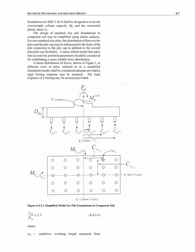
SECTION 6: FOUNDATION ANDABUTMENTDESIGN 6-7
foundations for SDC C&D shall be designed to resist theoverstrength column capacity Mpo and the associatedplastic shear Vpo.
The design of standard size pile foundations incompetent soil may be simplified using elastic analysis.For non-standard size piles, the distribution of forces to thepiles and the pile cap may be influenced by the fixity of thepile connection to the pile cap in addition to the overallpiles/pile cap flexibility. A more refined model that takesinto account the pertinent parameters should be consideredfor establishing a more reliable force distribution.
A linear distribution of forces, shown in Figure 1, atdifferent rows of piles, referred to as a simplifiedfoundation model, shall be considered adequate provided arigid footing response may be assumed. The rigidresponse of a footing may be assumed provided:
Figure 6.4.2-1 Simplified Model for Pile Foundations in Competent Soil.
5.2�ftg
ftg
DL
(6.4.2-1)
where:
Lftg = cantilever overhang length measured from

6-8 AASHTO GUIDE SPECIFICATIONS FOR LRFDSEISMIC BRIDGE DESIGN
the face of wall or column to the outside edge ofthe pile cap or footing (ft.)
Dftg = depth of the pile cap or footing (ft.)
Pile groups designed with the simplified foundationmodel may be sized to resist the plastic moment of thecolumn, Mp in lieu of Mpo specified in Article 8.5.
For conforming to capacity design principles, thedistribution of forces on these piles shall be examinedabout the x and y axis in addition to the diagonal directionof the foundation cap considering that the principal axes ofthe column correspond to x and y axis. For cases wherethe column principal axes do not correspond to pile thecapaxes, the designer shall investigate alternative orientationsto ensure hinging in the column.
For SDC C and D, the axial demand on an individualpile shall be taken as:
)(
)()(
)(
)()(
)(
)(
xpg
iycolxP
ypg
ixcolyP
ppilei
pilei
IcM
IcM
NP
TC
##�$%
$&' � (6.4.2-2)
in which:
��
�yN
iixxypg cnI
1
2)()( (6.4.2-3)
��
�xN
iiyyxpg cnI
1
2)()( (6.4.2-4)
where:
Ipg(y) = effective moment of inertia of pile groupabout the “y” axis (pile-ft.2)
Ipg(x) = effective moment of inertia of pile groupabout the “x” axis (pile-ft.2)
colxpM )( = the component of the column overstrength
plastic hinging moment capacity about the“x” axis (kip-ft.)
colypM )( = the component of the column overstrength
plastic hinging moment capacity about the“y” axis (kip-ft.)
Np = total number of piles in the pile group (pile)
nx = number of piles in a single parallel to the “x”axis
ny = number of piles in a single row parallel to the“y” axis
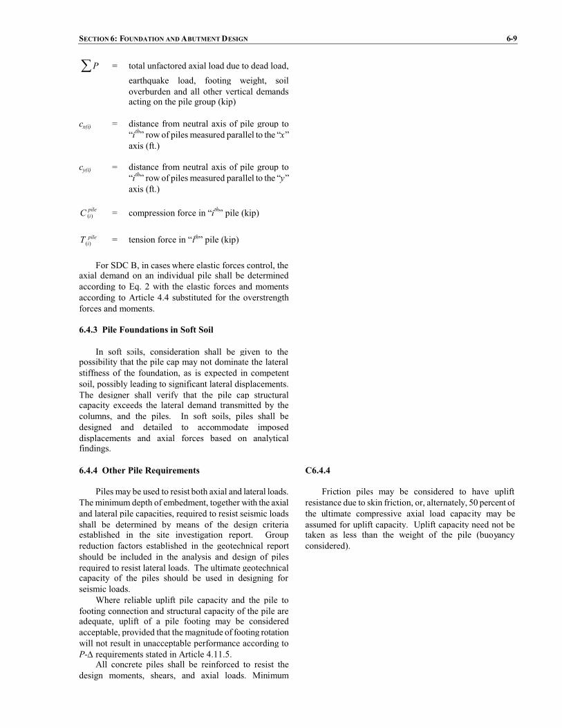
SECTION 6: FOUNDATION ANDABUTMENTDESIGN 6-9
�P = total unfactored axial load due to dead load,earthquake load, footing weight, soiloverburden and all other vertical demandsacting on the pile group (kip)
cx(i) = distance from neutral axis of pile group to“ith” row of piles measured parallel to the “x”axis (ft.)
cy(i) = distance from neutral axis of pile group to“ith” row of piles measured parallel to the “y”axis (ft.)
pileiC )( = compression force in “ith” pile (kip)
pileiT )( = tension force in “ith” pile (kip)
For SDC B, in cases where elastic forces control, theaxial demand on an individual pile shall be determinedaccording to Eq. 2 with the elastic forces and momentsaccording to Article 4.4 substituted for the overstrengthforces and moments.
6.4.3 Pile Foundations in Soft Soil
In soft soils, consideration shall be given to thepossibility that the pile cap may not dominate the lateralstiffness of the foundation, as is expected in competentsoil, possibly leading to significant lateral displacements.The designer shall verify that the pile cap structuralcapacity exceeds the lateral demand transmitted by thecolumns, and the piles. In soft soils, piles shall bedesigned and detailed to accommodate imposeddisplacements and axial forces based on analyticalfindings.
6.4.4 Other Pile Requirements
Piles may be used to resist both axial and lateral loads.The minimum depth of embedment, together with the axialand lateral pile capacities, required to resist seismic loadsshall be determined by means of the design criteriaestablished in the site investigation report. Groupreduction factors established in the geotechnical reportshould be included in the analysis and design of pilesrequired to resist lateral loads. The ultimate geotechnicalcapacity of the piles should be used in designing forseismic loads.
Where reliable uplift pile capacity and the pile tofooting connection and structural capacity of the pile areadequate, uplift of a pile footing may be consideredacceptable, provided that the magnitude of footing rotationwill not result in unacceptable performance according toP-� requirements stated in Article 4.11.5.
All concrete piles shall be reinforced to resist thedesign moments, shears, and axial loads. Minimum
C6.4.4
Friction piles may be considered to have upliftresistance due to skin friction, or, alternately, 50 percent ofthe ultimate compressive axial load capacity may beassumed for uplift capacity. Uplift capacity need not betaken as less than the weight of the pile (buoyancyconsidered).

6-10 AASHTO GUIDE SPECIFICATIONS FOR LRFDSEISMIC BRIDGE DESIGN
reinforcement shall be in accordance with Article 8.16.Footings shall be proportioned to provide the required
minimum embedment, clearance and spacing, requirementsaccording to the provisions of the AASHTO LRFD BridgeDesign Specifications. The spacing shall be increasedwhen required by subsurface conditions. For SDC D,embedment of pile reinforcement in the footing cap shallbe in accordance with Article 8.8.4.
6.4.5 Footing Joint Shear SDC C and D
All footing to columnmoment resistive joints in SDCC and D shall be proportioned such that the principalstresses meet the following criteria:
Principal compression:
'25.0 cc fp � (6.4.5-1)
Principal tension:
'38.0 ct fp � (6.4.5-2)
in which:
22
22 jvvv
t vff
p ����
����
��� (6.4.5-3)
22
22 jvvv
c vff
p �����
���� (6.4.5-4)
ftgftgeff
jvjv DB
Tv � (6.4.5-5)
��� pileicjv TTT )( (6.4.5-6)
where:
ftgeffB = effective width of footing (in.)
= cjD2 for circular columns (6.4.5-7)
= cjc DB � for rectangular columns (6.4.5-8)
and:
ftgjh
colv A
Pf � (6.4.5-9)
in which:

SECTION 6: FOUNDATION ANDABUTMENTDESIGN 6-11
ftgjhA = effective horizontal area at mid-depth of
the footing assuming a 45o spread awayfrom the boundary of the column in alldirections as shown in Figure 1 (in.2)
= 2)( ftgcj DD � for circular columns(6.4.5-10)
= ���
����
�����
����
��
22ftg
cjftg
c
DD
DB
for rectangular columns (6.4.5-11)
where:
Dcj = column width or diameter parallel to thedirection of bending (in.)
Bc = diameter or width of column or wallmeasured normal to the direction ofloading (ft.)
Dftg = depth of footing (in.)
Pcol = column axial force including the effects ofoverturning (kip)
'cf = uniaxial compressive concrete strength (ksi)
Tc = column tensile force associated with thecolumn overstrength plastic hingingmoment,Mpo (kip)
� pileiT )( = summation of the hold down force in the
tension piles (kip)
Transverse joint reinforcement shall be provided inaccordance with Article 8.8.8.
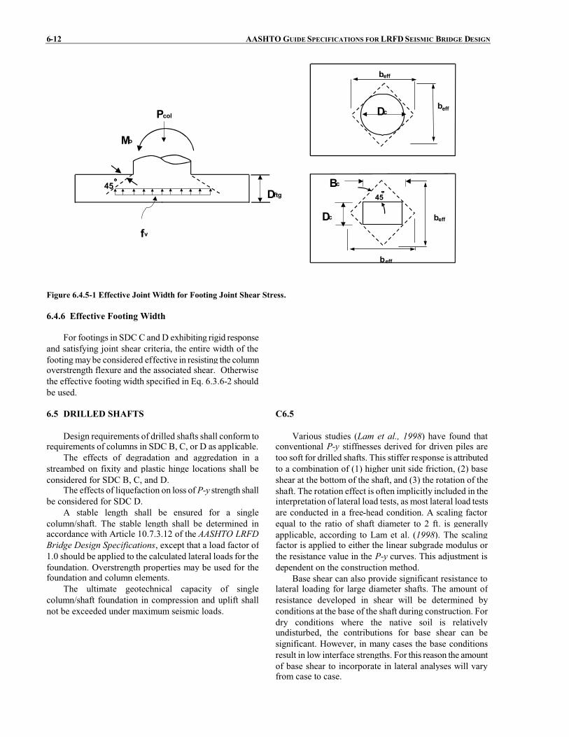
6-12 AASHTO GUIDE SPECIFICATIONS FOR LRFDSEISMIC BRIDGE DESIGN
beff
beffPcol
fv
Dftg45
beff
beff
45
Mo
Dc
Dc
Bc
Figure 6.4.5-1 Effective Joint Width for Footing Joint Shear Stress.
6.4.6 Effective Footing Width
For footings in SDCC and D exhibiting rigid responseand satisfying joint shear criteria, the entire width of thefooting maybe considered effective in resisting the columnoverstrength flexure and the associated shear. Otherwisethe effective footing width specified in Eq. 6.3.6-2 shouldbe used.
6.5 DRILLED SHAFTS
Design requirements of drilled shafts shall conform torequirements of columns in SDC B, C, or D as applicable.
The effects of degradation and aggredation in astreambed on fixity and plastic hinge locations shall beconsidered for SDC B, C, and D.
The effects of liquefaction on loss of P-y strength shallbe considered for SDC D.
A stable length shall be ensured for a singlecolumn/shaft. The stable length shall be determined inaccordance with Article 10.7.3.12 of the AASHTO LRFDBridge Design Specifications, except that a load factor of1.0 should be applied to the calculated lateral loads for thefoundation. Overstrength properties may be used for thefoundation and column elements.
The ultimate geotechnical capacity of singlecolumn/shaft foundation in compression and uplift shallnot be exceeded under maximum seismic loads.
C6.5
Various studies (Lam et al., 1998) have found thatconventional P-y stiffnesses derived for driven piles aretoo soft for drilled shafts. This stiffer response is attributedto a combination of (1) higher unit side friction, (2) baseshear at the bottom of the shaft, and (3) the rotation of theshaft. The rotation effect is often implicitly included in theinterpretation of lateral load tests, as most lateral load testsare conducted in a free-head condition. A scaling factorequal to the ratio of shaft diameter to 2 ft. is generallyapplicable, according to Lam et al. (1998). The scalingfactor is applied to either the linear subgrade modulus orthe resistance value in the P-y curves. This adjustment isdependent on the construction method.
Base shear can also provide significant resistance tolateral loading for large diameter shafts. The amount ofresistance developed in shear will be determined byconditions at the base of the shaft during construction. Fordry conditions where the native soil is relativelyundisturbed, the contributions for base shear can besignificant. However, in many cases the base conditionsresult in low interface strengths. For this reason the amountof base shear to incorporate in lateral analyses will varyfrom case to case.

SECTION 6: FOUNDATION ANDABUTMENTDESIGN 6-13
Lam et al. (1998) provides a detailed discussion of theseismic response and design of drilled shaft foundations.Their discussion includes a summary of procedures todetermine the stiffness matrix required to represent theshaft foundation in most dynamic analyses.
Drilled shaft foundations will often involve a singleshaft, rather than a group of shafts. This is not the case fordriven piles. In single shaft configuration the relativeimportance of axial and lateral response changes. Withoutthe equivalent of a pile cap, lateral-load displacement ofthe shaft becomes more critical than the load-displacementrelationships discussed above for driven piles.
The depth for stable conditions will depend on thestiffness of the rock or soil. Lower stable lengths areacceptable if the embedment length and the strength ofdrilled shaft provide sufficient lateral stiffness withadequate allowances for uncertainties in soil stiffness. InCaltrans practice, a stability factor of 1.2 is applied tosingle-column bents supported on a pile shaft.
6.6 PILE EXTENSIONS
Design requirements of pile extensions shall conformto requirements of columns in SDC B, C, or D asapplicable.
The effects of degradation and aggredation in astreambed on fixity and plastic hinges locations shall beconsidered in SDC B, C, and D.
The effects of liquefaction on loss of P-y strength shallbe considered in SDCD. Group reduction factors shall beincluded in the analysis and design of pile extensionssubjected to lateral loading in the transverse direction.
6.7 ABUTMENT DESIGN REQUIREMENTS
The participation of abutment walls in the overalldynamic response of bridge systems to earthquake loadingand in providing resistance to seismically induced inertialloads shall be considered in the seismic design of bridgesin accordance with Article 5.2.
Abutment design shall be consistent with the demandmodel consistent with the ERS used to assess intermediatesubstructure elements.
For conventional cantilever retaining wallconstruction, horizontal wall translation under dynamicactive pressure loading shall be considered acceptable.However, rotational instability may lead to collapse andthus shall be prevented.
6.7.1 Longitudinal Direction Requirements
The seismic design of free-standing abutments shouldtake into account forces arising from seismically-inducedlateral earth pressures, additional forces arising from wallinertia effects and the transfer of seismic forces from thebridge deck through bearing supports which do not slide
C6.7.1
These Guide Specifications have been prepared toacknowledge the abutment to be used as an EarthquakeResistant Element (ERE) and be a part of the EarthquakeResistant System (ERS). If designed properly, the reactivecapacity of the approach fill can provide significant benefit
6-14 AASHTO GUIDE SPECIFICATIONS FOR LRFDSEISMIC BRIDGE DESIGN
freely (e.g., elastomeric bearings).For free-standing abutments or retaining walls which
may displace horizontally without significant restraint(e.g., superstructure supported by sliding bearings), thedesign approach shall be similar to that of a free-standingretaining wall, except that longitudinal force from thebridge superstructure needs to be included in equilibriumevaluations, as the superstructuremoves outwards from thewall.
Earthquake-induced active earth pressures should becomputed using a horizontal acceleration of not less than50% of the effective peak ground acceleration coefficient,As. The pseudostatic Mononobe-Okabe method ofanalysis should be used for computing lateral active soilpressures during seismic loading. The effects of verticalacceleration may be omitted.
Abutment displacements having a maximum drift of4% may be tolerated. A limiting equilibrium conditionshould be checked in the horizontal direction. If necessary,wall design (initially based on a static service loadingcondition) should be modified tomeet the above condition.
For monolithic abutments where the abutment formsan integral part of the bridge superstructure, the abutmentshall be designed using one of the two alternativesdepending on the contribution level accounted for in theanalytical model:
� At a minimum, the abutment shall be designed toresist the passive pressure applied by theabutment backfill.
� If the abutment is part of the ERS and required tomobilize the full active pressure, a reductionfactor greater than or equal to 0.5 shall be appliedto the design forces provided a brittle failure doesnot exist in the load path transmitted to thesuperstructure.
For free-standing abutmentswhich are restrained fromhorizontal displacement by anchors or concrete batterpiles, earthquake-induced active earth pressures should becomputed using a horizontal acceleration equal to theeffective peak ground acceleration coefficient, As, as a firstapproximation. The Mononobe-Okabe analysis methodshould be used. Up to a 50% reduction in the horizontalacceleration may be used provided that the variouscomponents of the restrained wall can accommodate theincreased level of displacement demand.
to the bridge-foundation system.
SECTION 6: FOUNDATION ANDABUTMENTDESIGN 6-15
6.7.2 Transverse Direction Requirements
The provisions outlined in Article 5.2.4 shall befollowed depending on the mechanism of transfer ofsuperstructure transverse inertial forces to the bridgeabutments and following the abutment contribution to theEarthquake Resisting System (ERS) applicable for SDCCand D.
6.7.3 Other Requirements for Abutments
For SDC D, abutment pile foundation design may begoverned by liquefaction design requirements as outlinedin Article 6.8.
To minimize potential loss of bridge access arisingfrom abutment damage, monolithic or end diaphragmconstruction should be used for bridges less than 500 ft.
Settlement or approach slabs providing structuralsupport between approach fills and abutments shall beprovided for all bridges in SDC D. Slabs shall beadequately linked to abutments using flexible ties.
For SDC D, the abutment skew should be minimized.The tendency for increased displacements at the acutecorner of bridges with skewed abutments above 20° shouldbe considered. In the case where a large skew cannot beavoided, sufficient seat width in conjunction with anadequate shear key shall be designed to ensure against anypossible unseating of the bridge superstructure.
6.8 LIQUEFACTION DESIGN REQUIREMENTS
Liquefaction assessment should be required for abridge in SDC D.
If it is determined that liquefaction can occur at abridge site then the bridge shall be supported on deepfoundations or the ground improved so that liquefactiondoes not occur. For liquefied sites subject to lateral flow,the Engineer shall consider the use of large diameter shaftsin lieu of the conventional pile cap foundation type inorder to minimize lateral flow demands on the bridgefoundation. If liquefaction occurs then the bridge shall bedesigned and analyzed in two configurations as follows:
� Non-Liquefied Configuration. The structure shallbe analyzed and designed, assuming noliquefaction occurs using the ground responsespectrum appropriate for the site soil conditions.
� Liquefaction Configuration. The structure asdesigned in non-liquefied configuration aboveshall be reanalyzed and redesigned, if necessary,assuming that the layer has liquefied and theliquefied soil provides the appropriate residualresistance (i.e., P-y curves or modulus of sub-grade reaction values for lateral pile responseanalyses consistent with liquefied soilconditions). The design spectra shall be the same
C6.8
Liquefaction below a spread footing foundation canresult in three conditions that lead to damage or failure of abridge:
� Loss in bearing support which causes largevertical downward movement,
� Horizontal forces on the footing from lateral flowor lateral spreading of the soil, and
� Settlements of the soil as pore water pressures inthe liquefied layers dissipate.
Most liquefaction-related damage during pastearthquakes has been related to lateral flowor spreading ofthe soil. In these cases ground movements could be 3 ft. ormore. If the spread footing foundation is located above thewater table, as is often the case, it will be very difficult toprevent the footing from being displaced with the movingground. This could result in severe column distortion andeventual loss of supporting capacity.
In some underwater locations, it is possible that thelateral flow could move past the footing without causingexcessive loading; however, these cases will be limited.
If liquefaction with no lateral flow occurs for SDC Dbridges, then the only additional design requirements are

6-16 AASHTO GUIDE SPECIFICATIONS FOR LRFDSEISMIC BRIDGE DESIGN
as that used in non-liquefied configuration unlessa site-specific response spectra has beendeveloped using nonlinear, effective stressmethods that properly account for the buildup inpore-water pressure and stiffness degradation inliquefiable layers. The reduced response spectraresulting from the site-specific nonlinear,effective stress analyses shall not be less than 2/3of that used in the non-liquefied configuration.
For SDC D where liquefaction is identified, design-based plastic hinging in the foundation may be consideredprovided that the provisions of Article 3.3 are satisfied.
The Designer shall cover explicit detailing of plastichinging zones for both cases mentioned above since it islikely that locations of plastic hinges for the LiquefiedConfiguration are different than locations of plastic hingesfor the Non-Liquefied Configuration. Design requirementsof SDC D including shear reinforcement shall be met forthe liquefied and non-liquefied configuration.
those reinforcement requirements specified for the piles.Additional analyses are not required, although for essentialor critical bridges additional analysesmaybe considered inorder to assess the impact on the substructures above thefoundation.
If liquefaction and lateral flow are predicted to occurfor SDC D, a detailed evaluation of the effects of lateralflow on the foundation should be performed. Lateral flowis one of the more difficult issues to address because of theuncertainty in the movements that may occur.
Ultimate plastic rotation of the piles is permitted. Thisplastic rotation does imply that the piles and possibly otherparts of the bridge will need to be replaced if these levelsof deformation do occur. Design options range from (a) anacceptance of the movements with significant damage tothe piles and columns if the movements are large, to (b)designing the piles to resist the forces generated by lateralspreading. Between these options are a range of mitigationmeasures to limit the amount of movement to tolerablelevels for the desired performance objective. Pile groupeffects are not significant for liquefied soil.
SECTION 7: STRUCTURAL STEEL COMPONENTS
TABLE OF CONTENTS
7-i
7.1 GENERAL................................................................................................................................................................ 17.2 PERFORMANCE CRITERIA.................................................................................................................................. 4
7.2.1 Type 1............................................................................................................................................................. 47.2.2 Type 2............................................................................................................................................................. 47.2.3 Type 3............................................................................................................................................................. 5
7.3 MATERIALS............................................................................................................................................................ 67.4 MEMBER REQUIREMENTS FOR SDC C AND D ............................................................................................... 7
7.4.1 Limiting Slenderness Ratios ........................................................................................................................... 77.4.2 Limiting Width-Thickness Ratios ................................................................................................................... 77.4.3 Flexural Ductility for Members with Combined Flexural and Axial Load ................................................... 117.4.4 Combined Axial and Bending....................................................................................................................... 117.4.5 Weld Locations ............................................................................................................................................. 127.4.6 Ductile End Diaphragm in Slab-on-Girder Bridge........................................................................................ 127.4.7 Shear Connectors .......................................................................................................................................... 13
7.5 DUCTILE MOMENT RESISTING FRAMES AND SINGLE COLUMN STRUCTURES FOR SDC C AND D 147.5.1 Columns ........................................................................................................................................................ 157.5.2 Beams ........................................................................................................................................................... 157.5.3 Panel Zones and Connections ....................................................................................................................... 167.5.4 Multi-Tier Frame Bents ................................................................................................................................ 16
7.6 CONCRETE FILLED STEEL PIPES FOR SDC C AND D.................................................................................. 187.6.1 Combined Axial Compression and Flexure .................................................................................................. 197.6.2 Flexural Strength........................................................................................................................................... 207.6.3 Beams and Connections................................................................................................................................ 22
7.7 CONNECTIONS FOR SDC C AND D .................................................................................................................. 227.7.1 Minimum Strength for Connections to Ductile Members ............................................................................. 227.7.2 Yielding of Gross Section for Connections to Ductile Members .................................................................. 227.7.3 Welded Connections ..................................................................................................................................... 227.7.4 Gusset Plate Strength .................................................................................................................................... 227.7.5 Limiting Unsupported Edge Length to Thickness Ratio for a Gusset Plate .................................................. 237.7.6 Gusset Plate Tension Strength ...................................................................................................................... 237.7.7 Compression Strength of a Gusset Plate ....................................................................................................... 247.7.8 In-Plane Moment (Strong Axis).................................................................................................................... 247.7.9 In-Plane Shear Strength ................................................................................................................................ 257.7.10 Combined Moment, Shear, and Axial Forces ............................................................................................. 257.7.11 Fastener Capacity........................................................................................................................................ 26
7.8 ISOLATION DEVICES ......................................................................................................................................... 267.9 FIXED AND EXPANSION BEARINGS............................................................................................................... 26
7.9.1 Applicability ................................................................................................................................................. 267.9.2 Design Criteria.............................................................................................................................................. 277.9.3 Design and Detail Requirements................................................................................................................... 277.9.4 Bearing Anchorage ....................................................................................................................................... 28
TO BE UPDATED BY AASHTO PUBLICATIONS


SECTION 7
STRUCTURAL STEEL COMPONENTS
7-1
7.1 GENERAL
The Engineer shall demonstrate that a clear,straightforward load path (see Figure 1) within thesuperstructure, through the bearings or connections to thesubstructure, within the substructure, and ultimately to thefoundation exists. All components and connections shall becapable of resisting the imposed seismic load effectsconsistent with the chosen load path.
The flow of forces in the prescribed load path shall beaccommodated through all affected components and theirconnections including, but not limited to, flanges andwebsof main beams or girders, cross-frames, steel-to-steelconnections, slab-to-steel interfaces, and all components ofthe bearing assembly from bottom flange interface throughthe anchorage of anchor bolts or similar devices in thesubstructure. The substructure shall also be designed totransmit the imposed force effects into the soils beneath thefoundations.
The analysis and design of end diaphragms and cross-frames shall include the horizontal supports at anappropriate number of bearings, consistent withArticle 7.8and Article 7.9.
The following requirements shall apply to bridgeswitheither:
� a concrete deck that can provide horizontaldiaphragm action or
� a horizontal bracing system in the plane of the topflange, which in effect provides diaphragmaction.
A load path (see Figure 1) shall be established totransmit the inertial loads to the foundation based on thestiffness characteristics of the deck, diaphragms, cross-frames, and lateral bracing. Unless a more refined analysisis made, an approximate load path shall be assumed asfollows:
� The seismic inertia loads in the deck shall beassumed to be transmitted directly to the bearingsthrough end diaphragms or cross-frames.
� The development and analysis of the load paththrough the deck or through the top lateralbracing, if present, shall utilize assumedstructural actions analogous to those used for theanalysis of wind loadings.
Reference to AASHTO LRFD Bridge DesignSpecifications shall apply to the 2007 Fourth Edition withsubsequent updates pertinent to the articles mentioned inthis document.
C7.1
Most steel components of bridges are not expected tobehave in a cyclic inelastic manner during an earthquake.The provisions of this article are only applicable to thelimited number of components (such as specially detailedductile substructures or ductile diaphragms) whose stablehysteretic behavior is relied upon to ensure satisfactorybridge seismic performance. The seismic provisions of thisarticle are not applicable to the other steel membersexpected to remain elastic during seismic response. Inmoststeel bridges, the steel superstructure is expected (or can bedesigned) to remain elastic.
One span of the San Francisco-Oakland Bay Bridgecollapsed due to loss of support at its bearings during the1989 Loma Prieta earthquake, and another bridge sufferedsevere bearing damage (EERI, 1990). The end diaphragmsof some steel bridges suffered damage in a subsequentearthquake in northern California (Roberts, 1992). Duringthe 1994 Northridge earthquake some steel bridges,located close to the epicenter, sustained damage to eithertheir reinforced concrete abutments, connections betweenconcrete substructures and steel superstructures, steeldiaphragms or structural components near the diaphragms(Astaneh-Asl et al., 1994). Furthermore, a large number ofsteel bridges were damaged by the 1995 Hyogoken-Nanbu(Kobe) earthquake. The concentration of steel bridges inthe area of severe ground motion was considerably largerthan for any previous earthquake and some steel bridgescollapsed. Many steel piers, bearings, seismic restrainersand superstructure components suffered significant damage(Bruneau, Wilson and Tremblay, 1996). This experienceemphasizes the importance of ductile detailing in thecritical elements of steel bridges.
Research on the seismic behavior of steel bridges (e.g.Astaneh-Asl, Shen and Cho, 1993; Dicleli and Bruneau,1995a, 1995b; Dietrich and Itani, 1999; Itani et al.,1998a; McCallen and Astaneh-Asl, 1996; Seim, Inghamand Rodriguez, 1993; Uang et al., 2000; Uang et al.,2001; Zahrai and Bruneau 1998) and findings from recentseismic evaluation and rehabilitation projects (e.g. Astanehand Roberts, 1996; Ballard et al., 1996; Billings et al,1996; Dameron et al., 1995; Donikian et al., 1996; Gateset al., 1995; Imbsen et al., 1997; Ingham et al., 1996;Jones et al., 1997; Kompfner et al., 1996; Maroney 1996;Prucz et al., 1997; Rodriguez and Inghma, 1996;Schamber et al., 1997; Shirolé and Malik, 1993; Vincentet al., 1997) further confirm that seismically induceddamage is likely in steel bridges subjected to largeearthquakes and that appropriatemeasures shall be taken toensure satisfactory seismic performance.

7-2 AASHTO GUIDE SPECIFICATIONS FOR LRFDSEISMIC BRIDGE DESIGN
The intent of this Section is to ensure the ductileresponse of steel bridges during earthquakes. First,effective load paths should be provided for the entirestructure as outlined herein. Following the concept ofcapacity design, the load effect arising from the inelasticdeformations of part of the structure should be properlyconsidered in the design of other elements that are withinits load path.
Second, steel substructures should be detailed toensure stable ductile behavior. Note that the term“substructure” here refers to structural systems exclusive ofbearings and articulations. Steel substructures requireductile detailing to provide satisfactory seismicperformance.
Special consideration may be required for slip-criticalconnections that are subjected to cyclic loading. Someresearchers have expressed concern that the Poisson effectmay cause a reduction in plate thickness, when yielding ona component’s net section occurs during seismic response,which may translate into a reduced clamping action on thefaying surfaces after the earthquake. This has not beenexperimentally observed, nor noted in post-earthquakeinspections, but the impact of such a phenomenon wouldbe to reduce the slip-resistance of the connection, whichmay have an impact on fatigue resistance. This impact isbelieved to be negligible for a Category C detail for finitelife, and a Category D detail for infinite life. Design toprevent slip for the design earthquake should be alsoconsidered.
If the forces from the substructure corresponding tothe overstrength condition are used to design thesuperstructure, the distribution of these forces may not bethe same as that of the elastic demand analysis forces. TheEngineer may calculate a more refined distribution of theinertial forces present when a full inelastic mechanism hasdeveloped in the ERE’s. However, in lieu of such acalculation, the simpler linear distribution may be used, aslong as the applied forces are in equilibrium with thesubstructure’s plastic-moment forces. The vertical spatialrelationship between location of the substructure plasticresistance and the location of the superstructure inertiaforce application should also be considered in this analysis.
Diaphragms, cross-frames, lateral bracing, bearings,and substructure elements are part of an earthquake-resisting system in which the lateral loads and performanceof each element are affected by the strength and stiffnesscharacteristics of the other elements. Past earthquakes haveshown that when one of these elements responded in aductile manner or allowed some movement, damage waslimited. In the strategy followed herein, it is assumed thatductile plastic hinging in substructure or seismic isolatorunits are the primary source of energy dissipation.
Even if a component does not participate in the loadpath for seismic forces it will deform under the seismicloads. Such components should be checked that they havedeformation capacity sufficient to maintain their loadresistance under seismic-induced deformations.

SECTION 7: STRUCTURAL STEELCOMPONENTS 7-3
A continuous path is necessary for the transmission ofthe superstructure inertia forces to the substructure.Concrete decks have significant rigidity in their horizontalplane, and in short-to-medium slab-on-girder spans, theirresponse approaches rigid body motion. Therefore, thelateral loading of the intermediate diaphragms is minimal,consisting primarily of local tributary inertia forces fromthe girders themselves.
All bearings in a bridge do not usually resist loadsimultaneously, and damage to only some of the bearingsat one end of a span is not uncommon. When this occurs,high load concentrations can result at the location of theother bearings, and this effect should be taken into accountin the design of the end diaphragms and pier diaphragms.Also, a significant change in the load distribution betweenend diaphragm members and the pier may occur.
(a) Pile Footing. (b) Drilled Shaft
Note: Affected components shown are inclusive to Type 1, 2 and 3 and do reflect specificcomponents that are permitted to fuse under Type 1, 2 or 3 specified in Article 7.2.
Figure 7.1-1 Seismic Load Path and Affected Components.

7-4 AASHTO GUIDE SPECIFICATIONS FOR LRFDSEISMIC BRIDGE DESIGN
7.2 PERFORMANCE CRITERIA
This section shall apply to the design of superstructuresteel components. Those components shall be classifiedinto two categories: Ductile and Essentially Elastic. Basedon the characteristics of the bridge structure, the designermay utilize one of three options for a seismic designstrategy:
� Type 1 - Design a ductile substructure with anessentially elastic superstructure.
� Type 2 - Design an essentially elastic sub-structure with a ductile superstructure.
� Type 3 - Design an elastic superstructure andsubstructure with a fusing mechanism at theinterface between the superstructure and thesubstructure.
In this section, reference to an essentially elasticcomponent is used where the force demand to the nominalcapacity ratio of any member in the superstructure is lessthan 1.5.
Seismic design forces for individual members andconnections of bridges identified as Type 2 shall bedetermined by dividing the unreduced elastic forces by theappropriate ResponseModification Factor (R) as specifiedin Article 7.2.2. These factors shall only be used when allof the design requirements of this Section are satisfied. Acombination of orthogonal seismic forces equivalent to theorthogonal seismic displacement combination specified inArticle 4.4 shall be used to obtain the unreduced elasticforces.
C7.2
The design of ductile steel structural response is basedprimarily upon a forced-based, not displacement-based,seismic design approach. The provisions in this section areto be used in conjunction with the forced-based seismicdesign procedure utilized in the AASHTO LRFD BridgeDesign Specifications.
7.2.1 Type 1
For Type 1 structures, the designer shall refer toSection 8 or Article 7.5 of this document on designing fora ductile substructure as applicable to SDC C and D.
7.2.2 Type 2
For Type 2 structures, the design of the superstructureshall be accomplished using a force-based approach withan appropriate reduction for ductility. Those factors shallbe used for the design of transverse bracing members, toplaterals and bottom laterals. For SDC B, C, or D areduction factor, R, equal to 3 is used for ordinary bracingthat is a part of the Earthquake Resistant System (ERS) nothaving ductile end-diaphragms as defined in Article 7.4.6.The force reduction factor, R, may be increased to 4 forSDC D if the provisions in Article 7.4.6 are satisfied.
For simply supported spans with special end-diaphragms in compliance with Article 7.4.6, the locationof the diaphragms shall, as a minimum, be placed at theends of each span.

SECTION 7: STRUCTURAL STEELCOMPONENTS 7-5
For continuous spans where these special diaphragmsare used, the location of diaphragms shall, as a minimum,be placed over each bent and one cross-frame spacingadjacent to the opposite faces of the bent. The use ofspecial diaphragms at opposite faces of an in-span hingeshould be carefully assessed to ensure adequate verticalload capacity of the in-span hinge when subjected todeformations in the inelastic range.
For SDC B, C, or D a single angle bracing may beused for the diagonal member of the end-cross-frame. Asthis practice is typical and favored for ease of construction,the design process for a single angle bracing shall followAISC stand-alone document on LRFD DesignSpecification for Single-Angle Members.
For SDC D, double angles with stitch welds may beused as members of the end diaphragm ERS. Memberswith stitch welds shall follow the design process includedin the AISC LRFD Specifications Chapter E on compactand non-compact prismatic members subject to axialcompression through the centroidal axis.
7.2.3 Type 3
For Type 3 structures, the designer shall assess theoverstrength capacity for the fusing interface includingshear keys and bearings, then design for an essentiallyelastic superstructure and substructure. The minimumlateral design force shall be calculated using anacceleration of 0.4 g or the elastic seismic force whicheveris smaller. If isolation devices are used, the superstructureshall be designed as essentially elastic (see Article 7.8).
Other framing systems and frames that incorporatespecial bracing, active control, or other energy absorbingdevices, or other types of special ductile superstructureelements shall be designed on the basis of publishedresearch results, observed performance in past earthquakes,or special investigation, and provide a level of safetycomparable to those in the AASHTO LRFD Bridge DesignSpecifications.

7-6 AASHTO GUIDE SPECIFICATIONS FOR LRFDSEISMIC BRIDGE DESIGN
7.3 MATERIALS
The provisions of Section 6 of the AASHTO LRFDBridge Design Specifications for structural steel that isdesigned to remain essentially elastic during the designseismic event shall apply as applicable.
For SDC C and D, ductile substructure elements andductile end-diaphragms, as defined in Article 7.4.6inclusive through Article 7.5, shall be made of steelssatisfying the requirements of:
� ASTM A 709 Grade 50
� ASTM A 709 Grade 50W
� ASTM A 992
� ASTM A 500 Grade B
� ASTM A 501
For ASTM A 709 Grade 50 and Grade 50W andASTMA992 steels, the expected yield stress, Fye, shall betaken as 1.1 times the nominal yield stress, Fy.
For ASTM A 500 Grade B and ASTM A 501 steels,the expected yield stress, Fye, shall be taken as 1.4 timesthe nominal yield stress.
For SDC B, ASTM A 709 Grade 36 can be used. ForASTMA709 Grade 36 steel, the expected yield stress,Fye,shall be taken as 1.5 times the nominal yield stress.
C7.3
To ensure that the objective of capacity design isachieved, Grade 36 steel is not permitted for thecomponents expected to respond in a significantly ductilemanner. Grade 36 is difficult to obtain and contractorsoften substitute it with Grade 50 steel. Furthermore it has awide range in its expected yield and ultimate strength andlarge overstrength factors to cover the anticipated range ofproperty variations. The common practice of dual-certification for rolled shapes, recognized as a problemfrom the perspective of capacity design following theNorthridge earthquake, is now becoming progressivelymore common also for steel plates. As a result, only Grade50 steels are allowed for structures in SDC C and D.
In those instances when Grade 36 steel is permitted foruse (SDC B), capacity design should be accomplishedassuming and effective yield strength factor of 1.5.
The use of A 992 steel is explicitly permitted. Eventhough this ASTM grade is currently designated for“shapes for buildings”, there is work currently being doneto expand applicability to any shapes. ASTM A 992 steel,developed to ensure good ductile seismic performance, isspecified to have both a minimum and maximumguaranteed yield strength, and may be worthy ofconsideration for ductile energy-dissipating systems insteel bridges.
Since other steels may be used, provided that they arecomparable to the approved Grade 50 steels, HighPerformance Steel (HPS) Grade 50 would be admissible,but not HPS Grade 70W (or higher). Based on limitedexperimental data available, it appears that HPS Grade70W has a lower rotational ductility capacity and may notbe suitable for “ductile fuses” in seismic applications.
When other steels are used for energy dissipationpurposes, it is the responsibility of the designer to assessthe adequacy of material properties available and designaccordingly. Other steel members expected to remainelastic during earthquake should be made of steelsconforming to Article 6.4 of the AASHTO LRFD BridgeDesign Specifications.
The overstrength capacity shall be taken as theresistance of a member, connection or structure based uponthe nominal dimensions and details of the final section(s)chosen. The overstrength capacity shall be determinedusing the expected yield stress, Fye, and overstrengthfactor, �mo, as specified in Article 4.11.2.
The capacity design philosophy and the concept ofcapacity-protected element are defined in Article 4.11.
In Article 7.2, the nominal capacity shall be taken asthe resistance of a member, connection, or structure basedupon the expected yield strength, Fye, and the nominaldimensions and details of the final section(s), calculatedwith all material resistance factors, �, taken as 1.0.

SECTION 7: STRUCTURAL STEELCOMPONENTS 7-7
Welding requirements shall be compatible with theAASHTO/AWS D1.5M/D1.5:2002 Bridge Welding Code.Under-matched welds are not permitted for special seismichysteretic energy dissipating systems (such as ductilesubstructures and ductile diaphragms).
Steel members expected to undergo significant plasticdeformations during a seismic event shall meet thetoughness requirements of ASTM Standard A 709/A709M, Supplementary Requirement S84 (FractureCritical). Welds metal connecting these members shallmeet the toughness requirements specified in theAASHTO/AWS D1.5M/D1.5:2002 Bridge Welding Codefor Zone III (ANSI/AASHTO/AWS, 2002).
Steel members and weld materials should haveadequate notch toughness to perform in a ductile mannerover the range of expected service temperatures. The A709/A 709M S84 "Fracture-Critical Material ToughnessTesting and Marking" requirement, typically specifiedwhen the material is to be utilized in a fracture-criticalapplication as defined by AASHTO, is deemed to beappropriate to provide the level of toughness sought forseismic resistance. For weld metals, the AASHTO/AWSD1.5M/D1.5:2002 Bridge Welding Code requirement forZone III, familiar to the bridge engineering community, issimilar to the 20 ft.-lbs. at –20oF requirement proposed bythe SAC Joint Venture for weld metal in welded momentframe connections in building frames.
7.4 MEMBER REQUIREMENTS FOR SDC CAND D
7.4.1 Limiting Slenderness Ratios
Bracing members shall have a slenderness ratio,KL/r,less than 120. The length of a member shall be takenbetween the points of intersection of members. Aneffective length factor, K, of 0.85 of compressionmembersin braced structures shall be used unless a lower value canbe justified by an appropriate analysis. The slendernessparameter �c for axial compressive load dominantmembers, and �b for flexural dominant members shall notexceed the limiting values, �cp and �bp respectively asspecified in Table 1.
C7.4.1
In the ductile design of concentrically braced framesin buildings, the slenderness ratio limits for braces, up untilthe late 1990’s, were approximately 75% of the valuespecified here. The philosophy was to design braces tocontribute significantly to the total energy dissipationwhenin compression. Member slenderness ratio was restrictedbecause the energy absorbed by plastic bending of bracesin compression diminishes with increased slenderness. Toachieve these more stringent KL/r limits, particularly forlong braces, designers have almost exclusively used tubesor pipes for the braces. This is unfortunate as these tubularmembers are most sensitive to rapid local buckling andfracture when subjected to inelastic cyclic loading (in spiteof the low width-to-thickness limits prescribed). Reviewsof this requirement revealed that it may be unnecessary,provided that connections are capable of developing atleast the member capacity in tension. This is partly becauselarger tension brace capacity is obtained when design isgoverned by the compression brace capacity, and partlybecause low-cycle fatigue life increases for membershaving greater KL/r. As a result, seismic provisions forbuildings (AISC, 2005; CSA, 2001) have been revised topermit members having greaterKL/r values. The proposedrelaxed limits used here are consistent with the adoptedphilosophy for buildings.
7.4.2 Limiting Width-Thickness Ratios
For essentially elastic components, thewidth-thicknessratios shall not exceed the limiting value �r as specified inTable 1.
For ductile components, width-thickness ratios shallnot exceed the value �p as specified in Table 1.
C7.4.2
Early local buckling of braces prohibits the bracedframes from sustaining many cycles of load reversal. Bothlaboratory tests and real earthquake observations haveconfirmed that premature local buckling significantlyshortens the fracture life of Hollow Structural Section(HSS) braces. The more stringent requirement on the b/tratio for rectangular tubular sections subjected to cyclicloading is based on tests (Tang and Goel, 1987; Uang andBertero, 1986). The D/t limit for circular sections is

7-8 AASHTO GUIDE SPECIFICATIONS FOR LRFDSEISMIC BRIDGE DESIGN
identical to that in the AISC plastic design specifications(AISC, 1993; Sherman, 1976).
Table 7.4.1-1 Limiting Slenderness Parameters
in which:
EF
rKL y
c ����
��
"�� (slenderness parameter of axial compressive load dominant members) (7.4.1-1)
yb r
L�� (slenderness parameter of flexural moment dominant members) (7.4.1-2)
where:
Mu = factored moment demand acting on the member (kip-in.)
Mns = nominal flexural moment strength of a member (kip-in.)
Pu = factored axial compressive load acting on the member (kip)
Pn = nominal axial compressive strength of a member (kip)
�cp = limiting slenderness parameter for axial compressive load dominant members
�bp = limiting slenderness parameter for flexural moment dominant members
K = effective length factor of the member
L = unsupported length of the member (in.)
r = radius of gyration (in.)
ry = radius of gyration about minor axis (in.)
Fy = specified minimum yield strength of steel (ksi)
E = modulus of elasticity of steel (ksi)
Member Classification Limiting Slenderness Parameter �cp or �bpAxial Compression Load Dominant
ns
u
n
u
MM
PP � �cp 0.75
Ductile Members Flexural Moment Dominant
ns
u
n
u
MM
PP
�bpyFE086.0
Axial Compression Load Dominant
ns
u
n
u
MM
PP
� �cp 1.50Essentially Elastic/Capacity Protected Flexural Moment Dominant
ns
u
n
u
MM
PP �bp yF
E40.4

SECTION 7: STRUCTURAL STEELCOMPONENTS 7-9
The remainder of this page is left intentionally blank.

7-10 AASHTO GUIDE SPECIFICATIONS FOR LRFDSEISMIC BRIDGE DESIGN
Table 7.4.2-1 Limiting Width-Thickness Ratios.
Description of Elements Width-ThicknessRatios
Essentially ElasticComponents
��r
Ductile Members�p
UNSTIFFENEDELEMENTS
Flexure and uniformcompression in flanges ofrolled or built-up I-shapedsections.
tb
yFE
56.0yFE
30.0
Uniform compression inflanges of H-pile sections.
tb
yFE56.0
yFE45.0
Uniform compression inlegs of single angles, legsof double angle memberswith separators, or flangesof tees.
tb
yFE45.0
yFE30.0
Uniform compression instems of rolled tees.
td
yFE
75.0yFE
30.0
STIFFENED ELEMENTS
Rectangular HSS in axialcompression and/orflexural compression
tb
wth yF
E40.1
yFE
64.0 (tubes)
Unsupported width ofperforated cover plates. t
byFE86.1
yFE88.0
All other uniformlycompressed stiffenedelements that are supportedalong two edges.
tb
wth yF
E49.1
yFE
64.0 (laced)
yFE88.0 (others)
Webs in flexuralcompression or combinedflexural and axialcompression.
wth
���
����
�
��
yb
u
y PP
FE 74.0170.5
If ybu PP �� 125.0 , then:
���
����
�
��
yb
u
y PP
FE 54.1114.3
If ybu PP �� 125.0 , then:
yyb
u
y FE
PP
FE 49.133.212.1 ��
��
����
�
��
Longitudinally stiffenedplates in compression.
tb
yFkE
66.0yFkE
44.0
Round HSS in axialcompression or flexure
tD
yFE09.0
yFE044.0

SECTION 7: STRUCTURAL STEELCOMPONENTS 7-11
in which:
If n = 1, then:
48 3/1
3 �����
���btI
k s (7.4.2-1)
If n = 2, 3, 4, or 5, then:
43.143/1
43 �����
���
nbtIk s (7.4.2-2)
where:
k = plate buckling coefficient for uniform normal stress
n = number of equally spaced longitudinal compression flange stiffeners
Is = moment of inertia of a single longitudinal stiffener about an axis parallel to the flange and taken at the base of thestiffener (in.4)
�b = 0.9 resistance factor for flexure
Fy = specified minimum yield strength of steel (ksi)
E = modulus of elasticity of steel (ksi)
b = width of unstiffened element (in.)
d = overall depth of section (in.)
D = diameter of HSS tube (in.)
t = thickness of unstiffened element, plate thickness, or HSS wall thickness (in.)
tw = thickness of web plate (in.)
h = web depth (in.)
Pu = factored axial load acting on the member (kip)
Py = nominal axial yield strength of a member (kip)
7.4.3 Flexural Ductility for Members with CombinedFlexural and Axial Load
Ductility in bending may be utilized only if axial loadsare less than 60% of the nominal yield strength ofmember.Demand-to-capacity ratios or displacement ductilities shallbe kept less than unity if the axial load coinciding with themoment is greater than 60% of the nominal yield strengthof the member
7.4.4 Combined Axial and Bending
Members under combined axial and bending

7-12 AASHTO GUIDE SPECIFICATIONS FOR LRFDSEISMIC BRIDGE DESIGN
interaction shall be checked using interaction equationsfollowing AASHTO LRFD Bridge Design Specifications.
7.4.5 Weld Locations
Welds that are located in the expected inelastic regionof ductile components shall be made complete jointpenetration welds. Partial joint penetration groove weldsshall not be permitted in the expected inelastic regions.Splices shall not be permitted in the inelastic region ofductile components.
7.4.6 Ductile End Diaphragm in Slab-on-GirderBridge
Ductile end-diaphragms in slab-on-girder bridgesmaybe designed to be the ductile energy dissipating elementsfor seismic excitations in the transverse directions ofstraight bridges provided that:
� Specially detailed diaphragms, which are capableof dissipating energy in a stable manner withoutstrength degradation, can be used. The diaphragmbehavior shall be verified by cyclic testing.
� Only ductile energy dissipating systems withadequate seismic performance that has beenproven through cyclic inelastic testing are used.
� Design considers the combined relative stiffnessand strength of end-diaphragms and girders(including bearing stiffeners) in establishing thediaphragms strength and design forces toconsider for the capacity protected elements.
� The response modification factor, R, to beconsidered in design of the ductile diaphragm isgiven by:
41
DED
SUB
DED
SUB
KK
R KK
� ��� �� �� �� ��� �� �
(7.4.6-1)
where:
= displacement ductility capacity of theend diaphragm not to exceed 4
KDED= stiffness of the ductile end diaphragm(kip/in.)
KSUB = stiffness of the substructure (kip/in.)
� All details/connections of the ductile end-
SECTION 7: STRUCTURAL STEELCOMPONENTS 7-13
diaphragms are welded.
� The bridge does not have horizontal wind-bracingconnecting the bottom flanges of girders, unlessthe last wind bracing panel before each support isdesigned as a ductile panel equivalent and inparallel to its adjacent vertical end-diaphragm.
� An effective mechanism is present to ensuretransfer of the inertia-induced transversehorizontal seismic forces from the slab to thediaphragm.
Special design provisions for a ConcentricallyBracedFrame (CBF) or an Eccentrically Braced Frame (EBF),following theANSI/AISC Seismic Provisions for StructuralSteel Buildings 2005, shall be used in addition torequirements stated in this document.
Overstrength factors to be used to design the capacity-protected elements depend on the type of ductilediaphragm used, and shall be supported by availableexperimental research results.
7.4.7 Shear Connectors
Shear connectors should be provided on the flanges ofgirders, end cross frames or diaphragms to transfer seismicloads from the concrete deck to the abutments or piersupports in SDCA, B and C and shall be provided in SDCD.
For the transverse seismic load, the effective shearconnectors should be taken as those located on the flangesof girders, end cross frames or diaphragms that are nofurther than 9tw on each side of the outer projectingelements of the bearing stiffener group.
For the longitudinal seismic load, the effective shearconnectors should be taken as all those located on thegirder flange within the tributary span length of thesupport.
The seismic load at columns/piers should be taken asthe smaller of the following:
� The overstrength shear of the columns/piers
� 1.3 times the capacity of the bracing systems ifthey are considered as ductile seismic resistingsystems
The seismic load at abutments should be taken as thesmaller of the following:
� The overstrength shear of the shear keys
� 1.3 times the capacity of the bracing systems ifthey are considered as ductile seismic resistingsystems
C7.4.7
These provisions are primarily from Caltrans GuideSpecifications for Seismic Design of Steel Bridges(Caltrans 2001). The cross frames or diaphragms at theend of each span are the main components to transfer thelateral seismic loads from the deck down to the bearinglocations. Tests on a 0.4 scale experimental steel girderbridge (60 ft. long) conducted by University of Nevada,Reno (Carden, et al. 2001) indicated that too few shearconnectors between the girders and deck at the bridge enddid not allow the end cross frame to reach its ultimatecapacity. Supporting numerical analysis on a continuousmulti-span bridge showed that for non-composite negativemoment regions, the absence of shear connectors at the endof a bridge span caused large weak axis bending stresses inthe girders likely to cause buckling or yielding of thegirders before the capacity of the ductile component wasreached. Furthermore there were large forces in theintermediate cross frames, therefore, the end cross frameswere no longer the only main components transferringlateral seismic loads form the deck to the bearings. It is,therefore, recommended that adequate shear connectors beprovided above supports to transfer seismic lateral loads.These shear connectors can be placed on the girders or thetop struts of the end cross frame or diaphragms.

7-14 AASHTO GUIDE SPECIFICATIONS FOR LRFDSEISMIC BRIDGE DESIGN
Nominal strength of the shear connectors shall be inaccordance with Article 6.10.10 of the AASHTO LRFDBridge Design Specifications.
7.5 DUCTILE MOMENT RESISTING FRAMESAND SINGLE COLUMN STRUCTURES FOR SDCC AND D
This section applies to ductile moment-resistingframes and bents, constructed with steel I-shape beams andcolumns connected with their webs in a common plane.For SDC C or D, complying with a Type 1 performancecriteria design, the columns shall be designed as ductilestructural elements using a force reduction factor, R, of 4.The beams, the panel zone at column-beam intersectionsand the connections shall be designed as essentially elasticelements.
C7.5
It is believed that properly detailed fully weldedcolumn-to-beam or beam-to-column connections in themoment-resisting frames that would typically be used inbridges (See Figure C1) can exhibit highly ductile behaviorand perform adequately during earthquakes (contrary towhat was observed in buildings following Northridge). Asa result, strategies to move plastic hinges away from thejoints are not required in these specifications.
However, the designer may still elect to providemeasures (such as haunches at the end of yieldingmembers) to locate plastic hinges some distance away fromthe welded beam-to-column or column-to-beam joint(SAC, 1995, 1997, 2000).
Although beams, columns and panel zones can all bedesigned, detailed and braced to undergo severe inelasticstraining and absorb energy, the detailing requirements ofthis section address common bridge structures with deepnon-compact beams much stiffer in flexure than theirsupporting steel columns, and favor systems proportionedso that plastic hinges form in the columns. This isconsistent with the philosophy adopted for concretebridges.
Even though some bridges could be configured anddesigned to develop stable plastic hinging in beamswithout loss of structural integrity, the large gravity loadsthat are simultaneously be resisted by those beams alsomake plastic hinging at mid-span likely as part of theplastic collapse mechanism. The resulting deformationscan damage the superstructure (for example, thediaphragms or deck).
The special case of multi-tier frames is addressed inArticle 7.5.4.
Figure C7.5-1Example of Moment Frame/Bent.
SECTION 7: STRUCTURAL STEELCOMPONENTS 7-15
7.5.1 Columns
Width-to-thickness ratios of compression elements ofcolumns shall be in compliance with Table 7.4.2-1.
Full penetration flange and web welds shall bespecified at column-to-beam (or beam-to-column)connections.
The resistance of columns to combined axial load andflexure shall be determined in accordance with Article6.9.2.2 of the AASHTO LRFD Bridge DesignSpecifications. The factored axial compression due toseismic load and permanent loads shall not exceed0.20AgFy.
The shear resistance of the column web shall bedetermined in accordance with Article 6.10.9 of theAASHTO LRFD Bridge Design Specifications.
Except as specified herein, the potential plastic hingeregions (Article 4.11.8), near the top and base of eachcolumn, shall be laterally supported and the unsupporteddistance (i.e., between the plastic hinges) from theselocations shall not exceed the value determined fromTable7.4.1-1. The lateral supports shall be provided eitherdirectly to the flanges or indirectly through a column webstiffener or a continuity plate. Each column flange lateralsupport shall resist a force of not less than 2% of thenominal column flange strength (0.02bf tfFy) at the supportlocation. The possibility of complete load reversal shall beconsidered and the potential for plastic hinging about bothprincipal axes of a column shall be considered. Therequirements for lateral supports do not apply to potentialin-ground plastic hinging zones of pile bents
C7.5.1
At plastic hinge locations, members absorb energy byundergoing inelastic cyclic bendingwhilemaintaining theirresistance. Therefore, plastic design rules apply, namely,limitations on width-to-thickness ratios, web-to-flangeweld capacity, web shear resistance, and lateral support.
Axial load in columns is also restricted to avoid earlydeterioration of beam-column flexural strengths andductility when subject to high axial loads. Tests by Popovet al. (1975) showed that W-shaped columns subjected toinelastic cyclic loading suffered sudden failure due toexcessive local buckling and strength degradationwhen themaximum axial compressive load exceeded 0.50AgFy.Testsby Schneider et al. (1992) showed that moment-resistingsteel frames with hinging columns suffer rapid strength andstiffness deterioration when the columns are subjected tocompressive load equal to approximately 0.25AgFy. Mostbuilding codes set this limit at 0.30AgFy.
Where lateral support cannot be provided, the columnmaximum slenderness, KL/r, shall not exceed 60 andtransverse moments produced by the forces otherwiseresisted by the lateral bracing (including the second ordermoment due to the resulting column displacement) shall beincluded in the seismic load combinations.
Splices that incorporate partial joint penetrationgroove welds shall be located away from the plastic hingeregions as defined in Article 4.11.8 at a minimum distanceequal to the greater of:
� One-fourth the clear height of column
� Twice the column depth
� 39 in.
The requirement for lateral support is similar to Eq.6.10.8.2.3-1 of the AASHTO LRFD Bridge DesignSpecifications with a stress, f1, of zero (zero moment) atone end of the member, but modified to ensure inelasticrotation capacities of at least four times the elastic rotationcorresponding to the plastic moment. Consideration of anull moment at one end of the column accounts forchanges in location of the inflexion point of the columnmoment diagram during earthquake response. Figure 10.27in Bruneau et al. (1997) could be used to develop otherunsupported lengths limits.
Built-up columns made of fastened components (e.g.,bolted or riveted) are beyond the scope of theseGuidelines.
7.5.2 Beams
The factored resistance of the beams shall bedetermined in accordance with Article 6.12 of theAASHTO LRFD Bridge Design Specifications. At a jointbetween beams and columns the sum of the factoredresistances of the beams shall not be less than the sum ofthe probable resistances of the column(s) framing into thejoint. Unless otherwise demonstrated by rational analysis,
C7.5.2
Since plastic hinges are not expected to form inbeams, beams need not conform to plastic designrequirements.
The requirement for beam resistance is consistent withthe outlined capacity-design philosophy. The beams shouldeither resist the full elastic loads or be capacity-protected.In the extreme load situation, the capacity-protected beams
7-16 AASHTO GUIDE SPECIFICATIONS FOR LRFDSEISMIC BRIDGE DESIGN
the probable flexural resistance of columns, Mnx, shall betaken as the product of the overstrength factor times thecolumns nominal flexural resistance determined either inaccordance with Article 6.9.2.2 of the AASHTO LRFDBridge Design Specifications or by:
pxye
upxnx M
AFPMM ��
��
����
��� 118.1 (7.5.2-1)
where:
Mpx = plastic moment capacity of the member basedupon expected material properties (kip-ft.)
A = cross sectional area of member (in.2)
Fye = expected yield stress of structural steel member(ksi)
Pu = factored axial load acting on member (kip)
are required to have nominal resistances of not less thanthe combined effects corresponding to the plastic hinges inthe columns attaining their probable capacity and theprobable companion permanent load acting directly on thebeams. The columns' probable capacity should account forthe overstrength due to higher yield than specified yieldand strain hardening effects. The value specified in Article6.9.2.2 of the AASHTO LRFD Bridge DesignSpecifications, used in conjunction with the resistancefactor �f for steel beams in flexure of 1.00, is compatiblewith the AISC (2005) 1.1,Ry, used with a resistance factor� of 0.9 (here Ry is embedded in Fye).
Eq. 1 was developed for I-sections about strong axisbending and may not be appropriate for other sections.
7.5.3 Panel Zones and Connections
Column-beam intersection panel zones, momentresisting connections and column base connections shall bedesigned as Essentially Elastic Elements.
Panel zones shall be designed such that the verticalshearing resistance is determined in accordance withArticle 6.10.9 of the AASHTO LRFD Bridge DesignSpecifications.
Beam-to-column connections shall have resistance notless than the resistance of the beam stipulated in Article7.5.2.
Continuity plates shall be provided on both sides ofthe panel zone web and shall finish with total width of atleast 0.8 times the flange width of the opposing flanges.The continuity plate b/t ratio shall meet the limits forprojecting elements of Article 6.9.4.2 of the AASHTOLRFD Bridge Design Specifications. The continuity platesshall be proportioned to meet the stiffener requirementsstipulated in Article 6.10.11.2 of the AASHTO LRFDBridge Design Specifications and shall be connected toboth flanges and the web.
Flanges and connection plates in bolted connectionsshall have a factored net section ultimate resistancecalculated by Eq. 6.8.2.1-2, at least equal to the factoredgross area yield resistance given by Eq. 6.8.2.1-1, with Agand An in Article 6.8.2.1 of the AASHTO LRFD BridgeDesign Specifications taken here as the area of the flangesand connection plates in tension.
C7.5.3
The panel zone should either resist the full elastic load(i.e., R = 1.0) or be capacity-protected.
Column base connections should also resist the fullelastic loads (R =1.0) or be capacity-protected, unless theyare designed and detailed to dissipate energy.
Panel zone yielding is not permitted.There is a concern that doubler plates in panel zones
can be an undesirable fatigue detail. For plate-girdersections, it is preferable to specify a thicker web plate, ifnecessary, rather than use panel zone doubler plates.
7.5.4 Multi-Tier Frame Bents
For multi-tier frame bents, capacity design principlesas well as the requirements of Articles 7.5.1, 7.5.2, and7.5.3 may be modified by the engineer to achieve column
C7.5.4
Multi-tier frame bents are sometimes used becausethey are more rigid transversely than single-tier framebents. In such multi-tier bents, the intermediate beams are

SECTION 7: STRUCTURAL STEELCOMPONENTS 7-17
plastic hinging only at the top of the column. Columnplastic hinging at the base where fixity to the foundation isneeded shall be assessed where applicable.
significantly smaller than the top beam as they are notsupporting the gravity loads from the superstructure.
As a result, in a multi-tier frame, plastic hinging in thebeams may be unavoidable in all but the top beam. Tryingto ensure strong-beam weak-column design at all joints inmulti-tier bents may have the undesirable effect ofconcentrating all column plastic hinging in one tier, withgreater local ductility demands than otherwise expected indesign.
Using capacity design principles, the equations andintent of Article 7.5.1 and Article 7.5.2 may be modifiedby the designer to achieve column plastic hinging only atthe top and base of the column, and plastic hinging at theends of all intermediate beams, as shown in Figure C1.
Figure C7.5.4-1 Acceptable Plastic Mechanism for Multi-Tier Bent.
7-18 AASHTO GUIDE SPECIFICATIONS FOR LRFDSEISMIC BRIDGE DESIGN
7.6 CONCRETE FILLED STEEL PIPES FOR SDCC AND D
Concrete-filled steel pipes used as columns, piers, orpiles expected to develop full plastic hinging of thecomposite section as a result of seismic response shall bedesigned in accordance with Articles 6.9.2.2, 6.9.5,6.12.3.2.2, of the AASHTO LRFD Bridge DesignSpecifications as well as the requirements in this article.
C7.6
This article is only applicable to concrete-filled steelpipes without internal reinforcement, and connected in away that allows development of their full compositestrength. It is not applicable to design a concrete-filledsteel pipe that relies on internal reinforcement to providecontinuity with another structural element, or for which thesteel pipe is not continuous or connected in a way thatenables it to develop its full yield strength. When used inpile bent, the full composite strength of the plastic hingelocated below ground can only be developed if it can beensured that the concrete fill is present at that location.
Research (e.g., Alfawahkiri, 1997; Bruneau andMarson, 1999) demonstrates that the AASHTO equationsfor the design of concrete-filled steel pipes in combinedaxial compression and flexure (Articles 6.9.2.2, 6.9.5, and6.12.2.3.2 of the AASHTO LRFD Bridge DesignSpecifications) provide a conservative assessment of beam-column strength. Consequently, the calculated strength ofconcrete-filled steel pipes that could be used as columns inductile moment-resisting frames or pile-bents could besignificantly underestimated. This is not surprising giventhat these equations together are deemed applicable to abroad range of composite member types and shapes,including concrete-encased steel shapes.
While these equations may be perceived asconservative from a non-seismic perspective, an equationthat more realistically captures the plastic moment of suchcolumns is essential for capacity design. Capacity-protected elements should be designed with adequatestrength to elastically withstand the plastic hinging in thecolumns. Underestimating the plastic hinging forcetranslate into under-design of the capacity-protectedelements. A column unknowingly stronger than expectedwill not hinge prior to damaging foundations or otherundesirable locations in the structure. This can have severeconsequences, as the capacity-protected elements are notdetailed to withstand large inelastic deformations. Theprovisions of Article 7.3 are added to prevent thisbehavior.
For analysis, the flexural stiffness of the compositeconcrete filled pipe section may be taken as given in Eq.C1 which is a modified form of that given in Article5.7.4.3 of the AASHTO LRFD Bridge DesignSpecifications.
5.2)( cc
sseffIEIEEI �� (C7.6-1)
where:
Ic = moment of inertia of the concrete core (in.4)
Is = moment of inertia of the steel pipe (in.4)

SECTION 7: STRUCTURAL STEELCOMPONENTS 7-19
Es = modulus of elasticity of steel (ksi)
Ec = modulus of elasticity of concrete (ksi)
Alternatively, the flexural stiffness of the compositeconcrete filled pipe section may be taken as given in Eq.C2 which is a modified form of that given in Article6.9.5.1 of the AASHTO LRFD Bridge DesignSpecifications.
sss
csseff IE
AA
nIEEI ���
�
����
��� 352.088.0)( (C7.6-2)
where:
Ac = area of the concrete core (in.2)
As = area of the steel pipe (in.2)
Is = moment of inertia of the steel pipe (in.4)
n = modular ratio
7.6.1 Combined Axial Compression and Flexure
Concrete-filled steel pipe members required to resistboth axial compression and flexure and intended to beductile substructure elements shall be proportioned suchthat:
0.1��rc
u
r
u
MBM
PP
(7.6.1-1)
and
0.1�rc
u
MM (7.6.1-2)
in which:
1��rc
ro
PPB (7.6.1-3)
'cccrc fAP �� (7.6.1-4)
where:
Pr = factored nominal axial capacity of memberdetermined in accordance with Article 6.9.5 ofthe AASHTO LRFDBridgeDesign Specifications(kip)
Mrc = factored nominal moment capacity of memberdetermined in accordance with Article 7.6.2 (kip-
C7.6.1
The interaction equation is known to be reliable up toa maximum slenderness limit D/t < 0.96E/Fy,underestimating the flexural moment capacity by 1.25 onaverage (see Figure C1). It may significantly overestimatecolumns strength having greater D/t ratios.
The interaction equation is only applicable toconcrete-filled steel pipes. Revised equations may also beneeded to replace those of Article 6.9.2.2 of the AASHTOLRFD Bridge Design Specifications for other types ofcomposite columns (such as concrete-encased columns).
Figure C7.6.1-1 Interaction Curves for Concrete-Filled Pipe.
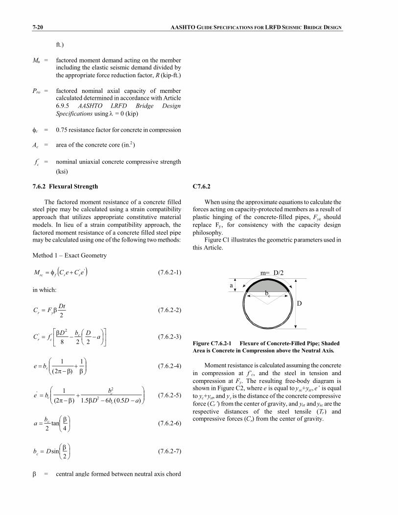
7-20 AASHTO GUIDE SPECIFICATIONS FOR LRFDSEISMIC BRIDGE DESIGN
ft.)
Mu = factored moment demand acting on the memberincluding the elastic seismic demand divided bythe appropriate force reduction factor, R (kip-ft.)
Pro = factored nominal axial capacity of membercalculated determined in accordance with Article6.9.5 AASHTO LRFD Bridge DesignSpecifications using� = 0 (kip)
�c = 0.75 resistance factor for concrete in compression
Ac = area of the concrete core (in.2)
'cf = nominal uniaxial concrete compressive strength
(ksi)
7.6.2 Flexural Strength
The factored moment resistance of a concrete filledsteel pipe may be calculated using a strain compatibilityapproach that utilizes appropriate constitutive materialmodels. In lieu of a strain compatibility approach, thefactored moment resistance of a concrete filled steel pipemay be calculated using one of the following twomethods:
Method 1 – Exact Geometry
� �''eCeCM rrfrc ��� (7.6.2-1)
in which:
2DtFC yr �� (7.6.2-2)
()
*+,
-���
��� ���� aDbDfC c
cr 228
2'' (7.6.2-3)
���
����
��
���"
�1
)2(1
cbe (7.6.2-4)
���
����
�
����
��"�
)5.0(65.1)2(1
2
2'
aDbDb
bec
cc (7.6.2-5)
��
���
� ��4
tan2cba (7.6.2-6)
���
�����2
sinDbc (7.6.2-7)
� = central angle formed between neutral axis chord
C7.6.2
When using the approximate equations to calculate theforces acting on capacity-protected members as a result ofplastic hinging of the concrete-filled pipes, Fye shouldreplace Fy, for consistency with the capacity designphilosophy.
Figure C1 illustrates the geometric parameters used inthis Article.
m= D/2
bcD
a
Figure C7.6.2-1 Flexure of Concrete-Filled Pipe; ShadedArea is Concrete in Compression above the Neutral Axis.
Moment resistance is calculated assuming the concretein compression at f’c, and the steel in tension andcompression at Fy. The resulting free-body diagram isshown in Figure C2, where e is equal to ysc+yst, e’ is equalto yc+yst, and yc is the distance of the concrete compressiveforce (Cr’) from the center of gravity, and yst and ysc are therespective distances of the steel tensile (Tr) andcompressive forces (Cr) from the center of gravity.

SECTION 7: STRUCTURAL STEELCOMPONENTS 7-21
line and the center point of the pipe found by therecursive equation (rad.)
yc
cys
DtFfD
fDFA
�
()
*+,
-��
���
� ���
���
� ����
���
���
��'2
2'2
125.0
4tan
2sin
2sin25.0
(7.6.2-8)
where:
D = outside diameter of steel pipe (in.)
t = pipe wall thickness (in.)
Fy = nominal yield stress of steel pipe (ksi)
'cf = nominal uniaxial concrete compressive strength
(ksi)
yschn yc
yst
Mrc = Cr’(yc+yst) + Cr (ysc+yst)
Tr
Cr’Cr
Figure C7.6.2-2 Free-Body Diagram Used to CalculateMoment Resistance of Concrete-Filled Pipe.
Method 2 – Approximate Geometry
A conservative value ofMrc is given by:
()
*+,
-��
���
�������� '232 )5.0()5.0(
32)2( cnynfrc fhtDtDFthZM
(7.6.2-9)in which:
)2(42 ''
'
cyc
ccn fFtDf
fAh��
� (7.6.2-10)
where:
�f = 1.0 resistance factor for structural steel in flexure
Ac = area of the concrete core (in.2)
D = outside diameter of steel pipe (in.)
t = pipe wall thickness (in.)
Z = plastic section modulus of steel pipe (in.3)
Fy = nominal yield stress of steel pipe (ksi)
'cf = nominal concrete compressive strength (ksi)
For capacity design purposes the moment calculatedby this approximate method shall be increased according toArticle 7.3.
In Method 2, a geometric approximation is made incalculating the area of concrete in compression bysubtracting the rectangular shaded area shown in Figure C3from the total area enclosed by the pipe (and dividing theresult by 2). Neutral axis is at height hn .
bc
hn
a
b-2t
a
hn
Figure C7.6.2-3 Flexure of Concrete-Filled Pipe –Illustrates Approximation Made in Method 2.
Method 2 (using approximate geometry) gives smallermoment capacities than Method 1 (exact geometry). Therequirement to increase the calculated moment by 10% forcapacity design when using the approximate method wasestablished from the ratio of the moment calculated byboth methods for aD/t of 10. The moment ratio decreasesas D/t increases.

7-22 AASHTO GUIDE SPECIFICATIONS FOR LRFDSEISMIC BRIDGE DESIGN
7.6.3 Beams and Connections
Capacity-protected members shall be designed toresist the forces resulting from hinging in the concrete-filled pipes calculated according to Article 7.6.2.
C7.6.3
Experimental work by Bruneau and Marson (1999),Shama et al. (2001), Azizinamini et al. (1999), provideexamples of full fixity connection details. In someinstances, full fixity may not be needed at both ends ofcolumns. Concrete-filled steel pipes, when used in pilebents, only require full moment connection at the pile-cap.
Design details for connecting concrete filled steelpipes to concrete members have been developed byPriestley et al. (1996).
7.7 CONNECTIONS FOR SDCC AND D
7.7.1 Minimum Strength for Connections to DuctileMembers
Connections and splices between or within membershaving a ductility demand greater than one shall bedesigned to have a nominal capacity at least 10% greaterthan the nominal capacity of theweaker connectedmemberbased on expected material properties.
7.7.2 Yielding of Gross Section for Connections toDuctile Members
Yielding of the gross section shall be checked (seeArticle 7.7.6). Fracture in the net section and the blockshear rupture failure shall be prevented.
7.7.3 Welded Connections
Partial joint penetration welds or fillet welds inregions of members subject to inelastic deformations shallnot be used. Outside of the inelastic regions, partial jointpenetration welds shall provide at least 150% of thestrength required by calculation, and not less than 75% ofthe strength of the connected parts regardless of the actionof the weld.
7.7.4 Gusset Plate Strength
Gusset plates shall be designed to resist shear, flexureand axial forces generated by overstrength capacities ofconnected ductile members and force demands ofconnected essentially elastic members. The design strengthshall be based on the effective width in accordance withWhitmore’s method.
C7.7.4
TheWhitmore (1952) effective width is defined as thedistance between two lines radiating outward at 30o anglesfrom the first row of bolts of the gusset plate along a linerunning through the last row of bolts as shown in FigureC1.

SECTION 7: STRUCTURAL STEELCOMPONENTS 7-23
Figure C7.7.4-1 Whitmore Effective Width.
7.7.5 Limiting Unsupported Edge Length toThickness Ratio for a Gusset Plate
The unsupported edge length to thickness ratio of agusset plate shall satisfy:
y
g
FE
tL
06.2� (7.7.5-1)
where:
Lg = unsupported edge length of the gusset plate (in.)
t = thickness of gusset plate (in.)
E = modulus of elasticity of steel (ksi)
Fy = nominal yield stress of steel pipe (ksi)
7.7.6 Gusset Plate Tension Strength
The only acceptable failure mode of gusset plates isyielding on the gross section that will ensure a ductilefailure mode. The factored tension strength of a gussetplate, �Pn, shall be taken as:
$.
$/
0
�
�����
bsbs
unu
ygyng
P
FAFAP (7.7.6-1)
in which:
if vntn AA 58.0� , then:
tnuvgybs AFAFP �� 58.0 (7.7.6-2)
if vntn AA 58.0 , then:
tgyvnubs AFAFP �� 58.0 (7.7.6-3)
C7.7.6
These provisions are similar to those found in Article6.13 of the AASHTO LRFD Bridge Design Specificationsbut have been modified for seismic design considerations.
Note that the minimum block shear failure mode maybe one of several failure modes. Investigation of allpotential block shear failure patterns is required todetermine the limiting resistance, Pbs.
The intent of these provisions is ensure that yieldingof the gross section occurs prior to fracture on the netsection and block shear failure (Caltrans 2001).

7-24 AASHTO GUIDE SPECIFICATIONS FOR LRFDSEISMIC BRIDGE DESIGN
where:
Avg = gross area of section along the plane resistingshear in block shear failure mode (in.2)
Avn = net area of section along the plane resisting shearin block shear failure mode (in.2)
Atg = gross area of section along the plane resistingtension in block shear failure mode (in.2)
Atn = net area of section along the plane resistingtension in block shear failure mode (in.2)
Ag = gross area of section along the plane resistingtension (in.2)
An = net area of section along the plane resistingtension (in.2)
Fy = nominal yield stress of steel (ksi)
Fu = minimum tensile strength of steel (ksi)
�bs = 0.80 resistance factor for block shear failuremechanisms
�u = 0.80 resistance factor for fracture on net section
�y = 0.95 resistance factor for yield on gross section
7.7.7 Compression Strength of a Gusset Plate
The nominal compression strength of the gusset plates,Png, shall be calculated according to AASHTO LRFDBridge Design Specifications.
7.7.8 In-Plane Moment (Strong Axis)
The nominal yield moment strength of a gusset plate,ngM , shall be taken as:
ygng FSM � (7.7.8-1)
where:
Sg = elastic section modulus of gusset plate about thestrong axis (in.3)
Fy = nominal yield stress of steel gusset plate (ksi)
The nominal plastic moment strength of a gusset plate,Mpg, shall be taken as:
ygpg FZM � (7.7.8-2)

SECTION 7: STRUCTURAL STEELCOMPONENTS 7-25
where:
Zg = plastic section modulus of gusset plate about thestrong axis (in.3)
7.7.9 In-Plane Shear Strength
The nominal shear strength of a gusset plate,Vng, shallbe taken as:
yggng FAV 58.0� (7.7.9-1)
where:
Agg = gross area of gusset plate (in.2)
Fy = nominal yield stress of steel gusset plate (ksi)
7.7.10 Combined Moment, Shear, and Axial Forces
The initial yielding strength of a gusset plate subjectedto a combination of in-plane moment, shear and axial forceshall be determined by the following equations:
0.1��rg
g
rg
g
MM
PP
(7.7.10-1)
and
0.12
����
����
��
rg
g
rg
g
VV
PP
(7.7.10-2)
where:
Vg = shear force acting on the gusset plate (kip)
Mg = moment acting on the gusset plate (kip-in.)
Pg = axial force acting on the gusset plate (kip)
Mrg = factored nominal yield moment capacity, �Mng,of the gusset plate from Article 7.7.8 (kip-in.)
Vrg = factored nominal shear capacity, �Vng, of thegusset plate from Article 7.7.9 (kip)
Prg = factored nominal yield axial capacity, �Png, of thegusset plate from Article 7.7.6 (kip)
Full yielding of shear-moment-axial load interaction fora plate shall be satisfy:

7-26 AASHTO GUIDE SPECIFICATIONS FOR LRFDSEISMIC BRIDGE DESIGN
0.1
12
4
2
�
((
)
*
++
,
-
���
����
��
���
����
�
����
����
��
rg
g
rg
g
rg
g
rpg
g
PP
VV
PP
MM
(7.7.10-3)
where:
Mrpg= factored nominal plastic moment capacity,�Mpg,of the gusset plate from Article 7.7.8 (kip-in.)
7.7.11 Fastener Capacity
Fastener capacity and other related designrequirements shall be determined in accordance withArticle 6.13 of the AASHTO LRFD Bridge DesignSpecifications.
7.8 ISOLATION DEVICES
Design and detailing of seismic isolation devices shallbe designed in accordance with the provisions of theAASHTO Guide Specifications for Seismic IsolationDesign.
C7.8
The requirements for analysis of bridges with seismicisolation are based on the 1999 AASHTO GuideSpecifications for Seismic IsolationDesign, which providerequirements for modeling seismic isolator units, includingthe use of propertymodification factors as given in Article7.3.
The force-deformation characteristics can be idealizedas a bilinear relationship with two key variables: secondslope stiffness and characteristic strength. The area underthe bilinear curve is equal to the energy dissipated byhysteretic work during cyclic loading. For design, theforce-deformation relationship can be represented by aneffective stiffness based on the secant stiffness, and adamping coefficient.
Bridges that have elastomeric or sliding bearings ateach pier may be designed as isolated structures.
7.9 FIXED AND EXPANSIONBEARINGS
7.9.1 Applicability
The provisions shall be taken to apply to pinbearings,roller bearings, rocker bearings, bronze or copper-alloysliding bearings, elastomeric bearings, spherical bearings,pot bearings and disc bearings in common slab-on-steelgirder bridges. Curved bridges, seismic isolation-typebearings, and structural fuse bearings are not covered bythis section.
C7.9.1
Bearings are important elements of the overallEarthquake Resistant System of a bridge structure. The1995 Kobe earthquake, and others that preceded it or haveoccurred since, clearly showed poor performance of somebearing types and the disastrous consequences that abearing failure can have on the overall performance of abridge. A consensus was developed that some testing ofbearings would be desirable provided a designer had theoption of providing restraints or permitting the bearing tofail if an adequate surface for subsequent movement isprovided. An example occurred in Kobe where a bearingfailed. The steel diaphragm and steel girder weresubsequently damaged because the girder became jammedon the failed bearing and could not move.
There have been a number of studies performedwhere

SECTION 7: STRUCTURAL STEELCOMPONENTS 7-27
girders slide either on specially designed bearings orconcrete surfaces. A good summary of the range of theresults that can be anticipated from these types of analysescan be found in Dicleli and Bruneau (1995).
7.9.2 Design Criteria
The selection of seismic design of bearings shall berelated to the strength and stiffness characteristics of boththe superstructure and the substructure.
Bearing design shall be consistent with the intendedseismic design strategy and the response of the wholebridge system.
Rigid-type bearings are assumed not to move inrestrained directions, and therefore the seismic forces fromthe superstructure shall be assumed to be transmittedthrough diaphragms or cross frames and their connectionsto the bearings, and then to the substructure withoutreduction due to local inelastic action along that load path.
Deformable-type bearings having less than full rigidityin the restrained directions but not specifically designed asbase isolators or fuses, have demonstrated a reduction inforce transmission and may be used in seismicapplications. The reduced force transmitted through thebearing shall not be less than 0.4 times the bearing deadload reaction.
7.9.3 Design and Detail Requirements
The Engineer should consider the impact on the lateralload path due to unequal participation of bearingsconsidering connection tolerances, unintendedmisalignments, the capacity of individual bearings, andskew effects.
Roller bearings or rocker bearings shall not be used innew bridge construction. Expansion bearings and theirsupports shall be designed in such a manner that thestructure can undergo movements in the unrestraineddirection not less than the seismic displacementsdetermined from analysis without collapse. Adequatesupport length shall also be provided for fixed bearings.
In their restrained directions, bearings shall bedesigned and detailed to engage at essentially the samemovement in each direction.
The frictional resistance of the bearing interfacesliding-surfaces shall be neglected when it contributes toresisting seismic loads. Conversely the frictional resistanceshall be conservatively calculated (i.e., overestimated)when the friction resistance results in the application ofgreater force effects to the structural components.
Elastomeric expansion bearings shall be providedwithanchorage to adequately resist the seismically inducedhorizontal forces in excess of those accommodated byshear in the pad. The sole plate and base plate shall bemade wider to accommodate the anchor bolts. Insertsthrough the elastomer shall not be allowed. The anchorbolts shall be designed for the combined effect of bending
C7.9.3
The types of tests that are required by these GuideSpecifications are similar to but significantly less extensivethan those required for seismically isolated bridges. Eachmanufacturer is required to conduct a prototypequalification test to qualify a particular bearing type andsize for its design forces or displacements. This series oftests only needs to be performed once to qualify thebearing type and size, whereas for seismically isolatedbridges, prototype tests are required on every project. Thequality control tests required on 1 out of every 10 bearingsis the same as that required for every isolator on seismicisolation bridge projects. The cost of the much moreextensive prototype and quality control testing of isolationbearings is approximately 10 to 15% of the total bearingcost, which is of the order of 2% of the total bridge cost.The testing proposed herein is much less stringent than thatrequired for isolation bearings and is expected to be lessthan 0.1% of the total bridge cost. However, the benefits oftesting are considered to be significant since ownerswouldhave a much higher degree of confidence that each newbearing will perform as designed during an earthquake.The testing capability exists to do these tests on full-sizebearings. The owner has the final determination on theextent of the testing requirements as deemed appropriatefor the type of bridge considered.

7-28 AASHTO GUIDE SPECIFICATIONS FOR LRFDSEISMIC BRIDGE DESIGN
and shear for seismic loads. Elastomeric fixed bearingsshall be provided with horizontal restraint adequate for thefull horizontal load.
Spherical bearings shall be evaluated for componentand connection strength and bearing stability.
Pot and disc bearings should not be used for seismicapplications where significant vertical acceleration ispresent. Where the use of pot and disc bearings isunavoidable, they shall be provided with an independentseismically resistant anchorage system.
7.9.4 Bearing Anchorage
Sufficient reinforcement shall be provided around theanchor bolts to develop the horizontal forces and anchorthem into the mass of the substructure unit. Potentialconcrete crack surfaces next to the bearing anchorage shallhave sufficient shear friction capacity to prevent failure.

SECTION 8: REINFORCED CONCRETE COMPONENTS
TABLE OF CONTENTS
8-i
8.1 GENERAL..............................................................................................................................................................8-18.2 SEISMIC DESIGN CATEGORY A.......................................................................................................................8-28.3 SEISMIC DESIGN CATEGORIES B, C, ANDD.................................................................................................8-2
8.3.1 General..........................................................................................................................................................8-28.3.2 Force Demands on SDC B............................................................................................................................8-28.3.3 Force Demands on SDC C and D .................................................................................................................8-28.3.4 Local Ductility Demands SDC D .................................................................................................................8-2
8.4 PROPERTIES AND APPLICATIONS OF REINFORCING STEEL, PRESTRESSING STEEL ANDCONCRETE FOR SDC B, C, AND D.........................................................................................................................8-3
8.4.1 Reinforcing Steel ..........................................................................................................................................8-38.4.2 Reinforcing Steel Modeling..........................................................................................................................8-38.4.3 Prestressing Steel Modeling..........................................................................................................................8-48.4.4 Concrete Modeling .......................................................................................................................................8-5
8.5 PLASTIC MOMENT CAPACITY FOR DUCTILE CONCRETE MEMBERS FOR SDC B, C, AND D............8-68.6 SHEAR DEMAND AND CAPACITY FOR DUCTILE CONCRETE MEMBERS FOR SDC B, C, AND D .....8-7
8.6.1 Shear Demand and Capacity.........................................................................................................................8-78.6.2 Concrete Shear Capacity for SDC B, C, and D.............................................................................................8-88.6.3 Shear Reinforcement Capacity ................................................................................................................... 8-108.6.4 Maximum Shear Reinforcement ................................................................................................................. 8-118.6.5 Minimum Shear Reinforcement..................................................................................................................8-118.6.6 Shear Reinforcement Capacity of Interlocking Spirals...............................................................................8-128.6.7 Minimum Vertical Reinforcement in Interlocking Portion.........................................................................8-128.6.8 Pier Wall Shear Capacity in the Weak Direction........................................................................................8-128.6.9 Pier Wall Shear Capacity in the Strong Direction ......................................................................................8-128.6.10 Pier Wall Minimum Reinforcement..........................................................................................................8-13
8.7 REQUIREMENTS FOR DUCTILE MEMBER DESIGN ................................................................................... 8-148.7.1 Minimum Lateral Strength..........................................................................................................................8-148.7.2 Maximum Axial Load in a Ductile Member in SDC C and D....................................................................8-14
8.8 LONGITUDINAL AND LATERAL REINFORCEMENT REQUIREMENTS..................................................8-158.8.1 Maximum Longitudinal Reinforcement......................................................................................................8-158.8.2 Minimum Longitudinal Reinforcement ......................................................................................................8-158.8.3 Splicing of Longitudinal Reinforcement in Columns Subject to Ductility Demands for SDC C and D.....8-158.8.4 Minimum Development Length of Reinforcing Steel for SDC C and D....................................................8-168.8.5 Anchorage of Bundled Bars in Ductile Components for SDC C and D .....................................................8-168.8.6 Maximum Bar Diameter for SDC C and D.................................................................................................8-168.8.7 Lateral Reinforcement Inside the Plastic Hinge Region for SDC C and D................................................. 8-178.8.8 Lateral Column Reinforcement Outside the Plastic Hinge Region for SDC C and D ................................8-188.8.9 Requirements for Lateral Reinforcement for SDC C and D.......................................................................8-188.8.10 Development Length for Column Bars Extended Into Oversized Pile Shafts for SDC C and D..............8-198.8.11 Lateral Reinforcement Requirements for Columns Supported on Oversized Pile Shafts for SDC C and D 8-198.8.12 Lateral Confinement for Oversized Pile Shafts for SDC C and D............................................................8-208.8.13 Lateral Confinement for Non-Oversized Strengthened Pile Shafts for SDC C and D..............................8-20
8.9 REQUIREMENTS FOR CAPACITY PROTECTEDMEMBERS......................................................................8-208.10 SUPERSTRUCTURE CAPACITY DESIGN FOR INTEGRAL BENT CAPS FOR LONGITUDINALDIRECTION FOR SDC C AND D ............................................................................................................................8-208.11 SUPERSTRUCTURE CAPACITY DESIGN FOR TRANSVERSE DIRECTION (INTEGRAL BENT CAP)FOR SDC C AND D................................................................................................................................................... 8-228.12 SUPERSTRUCTURE DESIGN FOR NON-INTEGRAL BENT CAPS FOR SDC C AND D.........................8-238.13 JOINT DESIGN FOR SDC C AND D ...............................................................................................................8-24
8.13.1 Joint Performance .....................................................................................................................................8-248.13.2 Joint Proportioning ...................................................................................................................................8-24
TO BE UPDATED BY AASHTO PUBLICATIONS

8-ii AASHTOGUIDE SPECIFICATIONS FOR LRFDSEISMIC BRIDGE DESIGN
8.13.3 Minimum Joint Shear Reinforcing ............................................................................................................8-258.13.4 Integral Bent Cap Joint Shear Design .......................................................................................................8-26
8.13.4.1 Joint Description .............................................................................................................................8-268.13.4.2 Joint Shear Reinforcement..............................................................................................................8-27
8.13.4.2.1 Vertical Stirrups....................................................................................................................8-278.13.4.2.2 Horizontal Stirrups................................................................................................................8-298.13.4.2.3 Horizontal Side Reinforcement.............................................................................................8-298.13.4.2.4 J-Bars....................................................................................................................................8-29
8.13.5 Non-Integral Bent Cap Joint Shear Design...............................................................................................8-308.13.5.1 Joint Shear Reinforcement..............................................................................................................8-30
8.13.5.1.1 Vertical Stirrups Outside the Joint Region ...........................................................................8-308.13.5.1.2 Vertical Stirrups Inside the Joint Region ..............................................................................8-328.13.5.1.3 Additional Longitudinal Cap Beam Reinforcement .............................................................8-328.13.5.1.4 Horizontal J-Bars..................................................................................................................8-32
8.14 COLUMN FLARES FOR SDC C AND D.........................................................................................................8-338.14.1 Horizontally Isolated Flares......................................................................................................................8-338.14.2 Integral Column Flares..............................................................................................................................8-338.14.3 Flare Reinforcement..................................................................................................................................8-33
8.15 COLUMN SHEAR KEY DESIGN FOR SDC C AND D..................................................................................8-348.16 CONCRETE PILES............................................................................................................................................8-34
8.16.1 Transverse Reinforcement Requirements .................................................................................................8-348.16.2 Cast-In-Place and Precast Concrete Piles..................................................................................................8-34
SECTION 8
REINFORCED CONCRETE COMPONENTS
8-1
Chapter 88.1 GENERAL C8.1
Design and construction of concrete componentsthat include superstructures, columns, piers, footingsand their connections shall conform to the requirementsof this Section.
For the purpose of this article, a vertical supportshall be considered to be a column if the ratio of theclear height to the maximum plan dimensions of thesupport is greater than 2.5. For a flared column, themaximum plan dimension shall be taken at the minimumsection of the flare. For supports with a ratio less than2.5, the provisions for piers of Articles 8.6.8 to 8.6.10shall apply.
A pier shall be designed as a pier member in itsstrong direction and a column in its weak direction.
The pile extensions of pile bents as well as drilledshafts and caissons shall be regarded as columns fordesign and detailing purposes.
If architectural flares or other treatments areprovided to columns adjacent to potential plastic hingezones, they shall be “structurally isolated” in such a waythat they do not add to the flexural strength capacity ofthe columns. If “structural isolation” is not used then thecolumn and adjacent structural elements shall bedesigned to resist the forces generated by increasedflexural strength capacity according to Article 8.14.
The 1989 Loma Prieta and 1994 Northridgeearthquakes confirmed the vulnerability of columns withinadequate transverse reinforcement and inadequateanchorage of longitudinal reinforcement. Also ofconcern are:
� lack of adequate reinforcement for positivemoments that may occur in the superstructureover monolithic supports when the structure issubjected to longitudinal dynamic loads
� lack of adequate shear strength in jointsbetween columns and bent caps undertransverse dynamic loads
� inadequate reinforcement for torsion,particularly in outrigger-type bent caps
� inadequate transverse reinforcement for shearand for restraint against global buckling oflongitudinal bars (“bird caging”)
The purpose of the design is to ensure that a columnis provided with adequate ductility and is forced to yieldin flexure and that the potential for a shear, compressionfailure due to longitudinal bar buckling, or loss ofanchorage mode of failure is minimized.
The actual ductility demand on a column or pier is acomplex function of a number of variables, including:
� Earthquake characteristics, including duration,frequency content and near-field (or pulse)effects
� Design force level
� Periods of vibration of the bridge
� Shape of the inelastic hysteresis loop of thecolumns, and hence effective hystereticdamping
� Elastic damping coefficient
� Contributions of foundation and soil conditionsto structural flexibility
� Spread of plasticity (plastic hinge length) in thecolumn
The damage potential of a column is also related tothe ratio of the duration of strong ground shaking to the
8-2 AASHTO GUIDE SPECIFICATIONS FOR LRFD SEISMICBRIDGE DESIGN
natural period of vibration of the bridge.The definition of a column in this article is provided
as a guideline to differentiate between the additionaldesign requirements for a wall-type pier and therequirements for a column.
Certain oversize columns exist for architectural oraesthetic reasons. These columns, if fully reinforced,place excessive demands of moment, shear, or both, onadjoining elements. The designer should strive to“isolate structurally” those architectural elements that donot form part of the primary energy dissipation systemthat are located either within or in close proximity toplastic hinge zones. Nevertheless, the architecturalelements should remain serviceable throughout the lifeof the structure. For this reason, minimum steel fortemperature and shrinkage should be provided. Whenarchitectural flares are not isolated, Article 8.14.2requires that the design shear force for a flared columnbe the worst case calculated using the overstrengthmoment of the oversized flare or the shear generated bya plastic hinge at the bottom of the flare.
8.2 SEISMIC DESIGN CATEGORY A
The provisions of Article 4.6 for force demand shallbe satisfied. The provisions of Article 4.12 for seatwidth shall be satisfied.
8.3 SEISMIC DESIGN CATEGORIES B, C, AND D
8.3.1 General
Initial sizing of columns should be performed usingStrength and Service load combinations defined in theAASHTO LRFD Bridge Design Specifications.
C8.3.1
For post-tensioned box-girders, it is recommendedthat the least dimension of column or pier wall be lessthan or equal to the superstructure depth. See Article8.10.
8.3.2 Force Demands on SDC B
The design forces shall be the lesser of the forcesresulting from the overstrength plastic hinging momentcapacity or unreduced elastic seismic forces in columnsor pier walls. Force demands shall be less thancapacities established in Articles 8.5 and 8.6.
C8.3.2
SDC B structures are designed and detailed toachieve a displacement ductility, D, of at least 2.
8.3.3 Force Demands on SDC C and D
The design forces shall be based on forces resultingfrom the overstrength plastic hinging moment capacityor the maximum connection capacity following thecapacity design principles specified in Article 4.11.
8.3.4 Local Ductility Demands SDC D
The local displacement ductility demands, D, ofmembers shall be determined based on the analysismethod adopted in Section 5. The local displacementductility demand shall not exceed the maximumallowable displacement ductilities established in Article

SECTION 8: REINFORCED CONCRETE COMPONENTS 8-3
4.9.
8.4 PROPERTIES AND APPLICATIONS OFREINFORCING STEEL, PRESTRESSING STEELAND CONCRETE FOR SDCB, C, AND D
For SDC B and C, the expected material propertiesshall be used to determine the section stiffness andoverstrength capacities.
For SDC D, the expected material properties shallbe used to determine section stiffness, overstrengthcapacities, and displacement capacities.
8.4.1 Reinforcing Steel
Reinforcing bars, deformed wire, cold-drawn wire,welded plain wire fabric, and welded deformed wirefabric shall conform to the material standards asspecified in the AASHTO LRFD Bridge DesignSpecifications.
Use of high strength high alloy bars with anultimate tensile strength of up to 250 ksi, shall bepermitted for longitudinal column reinforcement forseismic loading provided that it can be demonstratedthrough testing that the low cycle fatigue properties arenot inferior to normal reinforcing steels with yieldstrengths of 75 ksi or less.
C8.4.1
High-strength reinforcement reduces congestion andcost as demonstrated by Mander and Cheng (1999).However it is important to ensure that the cyclic fatiguelife is not inferior when compared to ordinary mild steelreinforcing bars. Mander, Panthaki, and Kasalanati,(1994) have shown that modern high-alloy prestressingthreadbar steels can have sufficient ductility to justifytheir use in seismic design.
The modulus of toughness is defined as the areabeneath the monotonic tensile stress-strain curve frominitial loading (zero stress) to fracture.
Use of wire rope or strand shall be permitted forspirals in columns if it can be shown through testing thatthe modulus of toughness exceeds 14 ksi.
For SDC B and C, use of ASTM A 706 or ASTM A615 Grade 60 reinforcing steel shall be permitted.
For SDC D, ASTM A 706 reinforcing steel inmembers where plastic hinging is expected shall beused.
8.4.2 Reinforcing Steel Modeling
Reinforcing steel shall be modeled with a stress-strain relationship that exhibits an initial elastic portion,a yield plateau, and a strain hardening range in whichthe stress increases with strain, as shown in Figure 1. Inlieu of specific data, the steel reinforcement propertiesprovided in Table 1 should be used.
Within the elastic region the modulus of elasticity,Es, shall be taken as 29,000 ksi.
C8.4.2
The steel reinforcement properties provided inTable 1 are based upon data collected by Caltrans.
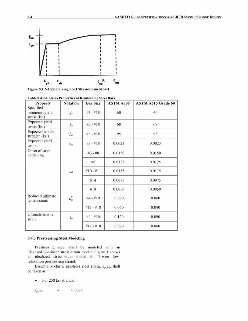
8-4 AASHTO GUIDE SPECIFICATIONS FOR LRFD SEISMICBRIDGE DESIGN
Figure 8.4.2-1 Reinforcing Steel Stress-Strain Model.
Table 8.4.2-1 Stress Properties of Reinforcing Steel Bars.Property Notation Bar Size ASTM A706 ASTM A615 Grade 60
Specifiedminimum yieldstress (ksi)
fy #3 - #18 60 60
Expected yieldstress (ksi) fye #3 - #18 68 68
Expected tensilestrength (ksi) fue #3 - #18 95 95
Expected yieldstrain �ye #3 - #18 0.0023 0.0023
Onset of strainhardening #3 - #8 0.0150 0.0150
#9 0.0125 0.0125
�sh #10 - #11 0.0115 0.0115
#14 0.0075 0.0075
#18 0.0050 0.0050
Reduced ultimatetensile strain
Rsu� #4 - #10 0.090 0.060
#11 - #18 0.060 0.040
Ultimate tensilestrain �su #4 - #10 0.120 0.090
#11 - #18 0.090 0.060
8.4.3 Prestressing Steel Modeling
Prestressing steel shall be modeled with anidealized nonlinear stress-strain model. Figure 1 showsan idealized stress-strain model for 7-wire low-relaxation prestressing strand.
Essentially elastic prestress steel strain, �ps,EE, shallbe taken as:
� For 250 ksi strands:
�ps,EE = 0.0076

SECTION 8: REINFORCED CONCRETE COMPONENTS 8-5
and,
� For 270 ksi strands:
�ps,EE = 0.0086
Reduced ultimate prestress steel strain shall betaken as:
Rups ,� = 0.03
The stress, fps, in the prestressing steel shall be takenas:
� For 250 ksi strands:
0.0076when500,28 ���� pspspsf (8.4.3-1)
0.0076when0.25-250 ���
� psps
psf (8.4.3-2)
� For 270 ksi strands:
0.0086when500,28 ���� pspspsf (8.4.3-3)
0086.0when007.0
0.04-270 ����
� psps
psf
(8.4.3-4)
where:
�ps = strain in prestressing steel
Figure 8.4.3-1 Prestressing Strand Stress-StrainModel.
8.4.4 Concrete Modeling
A stress-strain model for confined and unconfinedconcrete shall be used as depicted in Figure 1. Mander’sstress strain model for confined concrete should be used
C8.4.4
For more information on Mander’s confinedconcrete model, refer to Mander et al. (1988), Mander etal. (1988), and Priestley et al. (1996).

8-6 AASHTO GUIDE SPECIFICATIONS FOR LRFD SEISMICBRIDGE DESIGN
for determining section response.The expected concrete compressive strength, cef � ,
shall be taken as the most probable long-term concretestrength based upon regional experience and shall betaken as:
1.3ce cf f� �� (8.4.4-1)
where:
cf � = compressive strength of concrete (ksi)
The unconfined concrete compressive strain at themaximum compressive stress �co shall be taken as equalto 0.002. The ultimate unconfined compression strain �spbased on spalling shall be taken as equal to 0.005.
The confined compressive strain, �cc, and theultimate compressive strain, �cu, for confined concreteshould be computed using Mander’s model.
Figure 8.4.4-1 Concrete Stress-Strain Model.
8.5 PLASTIC MOMENT CAPACITY FORDUCTILE CONCRETE MEMBERS FOR SDC B,C, AND D
C8.5
The plastic moment capacity of all ductile concretemembers shall be calculated by moment-curvature (M-�)analysis based on the expected material properties. Themoment curvature analysis shall include the axial forcesdue to dead load together with the axial forces due tooverturning as given in Article 4.11.4.
The M-� curve should be idealized with an elasticperfectly plastic response to estimate the plastic momentcapacity of a member’s cross section. The elastic portionof the idealized curve shall pass through the pointmarking the first reinforcing bar yield. The idealizedplastic moment capacity shall be obtained by equatingthe areas between the actual and the idealized M-�curves beyond the first reinforcing bar yield point asshown in Figure 1.
Moment curvature analysis obtains the curvaturesassociated with a range of moments for a cross sectionbased on the principles of strain compatibility andequilibrium of forces. A moment-curvature analysisbased on strain compatibility and nonlinear stress-strainrelations can be used to determine plastic limit states.The results from this rational analysis are used toestablish the rotational capacity of plastic hinges as wellas the associated plastic deformations. The process ofusing the moment-curvature sectional analysis todetermine the lateral load-displacement relationship of aframe, column or pier is known as a “pushoveranalysis.”

SECTION 8: REINFORCED CONCRETE COMPONENTS 8-7
Figure 8.5-1 Moment-Curvature Model.
8.6 SHEAR DEMAND AND CAPACITY FORDUCTILE CONCRETE MEMBERS FOR SDC B,C, AND D
8.6.1 Shear Demand and Capacity
The shear demand for a column, Vu, in SDC B shallbe determined based on the lesser of:
� The force obtained from a linear elastic seismicanalysis
� The force, Vpo, corresponding to plastic hingingof the column including an overstrength factor
The shear demand for a column, Vu, in SDC C or Dshall be determined based on the force, Vpo, associated
C8.6.1
The requirements of this Article are, in part,intended to avoid column shear failure by using theprinciples of “capacity protection”. For SDC C and D,the design shear force is specified as a result of theoverstrength plastic moment capacity, regardless of theelastic earthquake design forces. This requirement isnecessary because of the potential for superstructurecollapse if a column fails in shear.
A column may be loaded in either the longitudinalor transverse direction. The shear force corresponding tothe maximum shear developed in either direction for
The expected nominal moment capacity, Mne, foressentially elastic response shall be based on theexpected concrete and reinforcing steel strengths whenthe concrete strain reaches a magnitude of 0.003.
In order to determine force demands on capacity-protected members connected to a hinging member, aoverstrength magnifier, �mo, shall be applied to theplastic moment capacity of the hinging member suchthat:
pmopo MM �� (8.5-1)
where:
Mp = idealized plastic moment capacity of reinforcedconcrete member based upon expected materialproperties (kip-ft.)
Mpo = overstrength plastic moment capacity (kip-ft.)
�mo = overstrength magnifier= 1.2 for ASTM A 706 reinforcement= 1.4 for ASTM A 615 Grade 60 reinforcement
The overstrength magnifier, �mo, accounts for:
� Material strength variations between thecolumn and adjacent members (e.g.superstructure, bent cap, footings, oversizedpile shafts)
� Column moment capacities greater than theidealized plastic moment capacity

8-8 AASHTO GUIDE SPECIFICATIONS FOR LRFD SEISMICBRIDGE DESIGN
with the overstrength moment, Mpo, defined in Article8.5 and outlined in Article 4.11.
The column shear strength capacity within theplastic hinge region as specified in Article 4.11.7 shallbe calculated based on the nominal material strengthproperties and shall satisfy:
noncircular columns should be used for thedetermination of the transverse reinforcement.
uns VV �� (8.6.1-1)
in which:
scn VVV �� (8.6.1-2)
where:
�s = 0.85 for shear in reinforced concrete
Vn = nominal shear capacity of member (kip)
Vc = concrete contribution to shear capacity asspecified in Article 8.6.2 (kip)
Vs = reinforcing steel contribution to shear capacityas specified in Article 8.6.3 (kip)
The factored nominal shear resistance for membersoutside the plastic hinge region as defined in Article4.11.7 shall be determined in accordance with theAASHTO LRFD Bridge Design Specifications.
8.6.2 Concrete Shear Capacity for SDC B, C, and D
The concrete shear capacity, Vc, of membersdesigned for SDC B, C and D shall be taken as:
ecc AvV � (8.6.2-1)
in which:
ge AA 8.0� (8.6.2-2)
if Pu is compressive:
$$.
$$/
0
1��
��
����
��1��
'
'
'
'047.0
11.0min
21032.0
c
c
cg
uc
f
ff
APv (8.6.2-3)
otherwise:
vc = 0 (8.6.2-4)
for circular columns with spiral or hoop reinforcing:
367.315.0
3.0 ' ����1� Dsf (8.6.2-5)
C8.6.2
The shear provisions in the AASHTO LRFD BridgeDesign Specifications are not applicable for sections thatare expected to accommodate a significant amount ofplastic deformation. The concrete shear strength withinthe plastic hinge region degrades as the ductility demandincreases but is improved with increasing transverseconfinement.

SECTION 8: REINFORCED CONCRETE COMPONENTS 8-9
35.0� � yhss ff (8.6.2-6)
'
4sDAsp
s � (8.6.2-7)
for rectangular columns with ties:
367.315.0
3.0 ' ����1� Dwf (8.6.2-8)
35.02 � � yhww ff (8.6.2-9)
bsAv
w � (8.6.2-10)
where:
Ag = gross area of member cross section (in.2)
Pu = ultimate compressive force acting on section(kip)
Asp = area of spiral or hoop reinforcing bar (in.2)
s = pitch of spiral or spacing of hoops or ties (in.)
D’ = diameter of spiral or hoop for circular column(in.)
Av = total cross sectional area of shear reinforcingbars in the direction of loading (in.2)
b = width of rectangular column (in.)
fyh = nominal yield stress of transverse reinforcing(ksi)
'cf = nominal concrete compressive strength (ksi)
D = maximum local displacement ductility ratio ofmember
For SDC B, the concrete shear capacity, Vc, of asection within the plastic hinge region shall bedetermined using:
D = 2
For SDC C, the concrete shear capacity of a sectionwithin the plastic hinge region shall be determinedusing:
D = 3
For SDC D, the concrete shear capacity of a sectionwithin the plastic hinge region shall be determined

8-10 AASHTO GUIDE SPECIFICATIONS FOR LRFD SEISMICBRIDGE DESIGN
using:
D = value determined from Eq. 4.9-5
8.6.3 Shear Reinforcement Capacity
For members that are reinforced with circularhoops, spirals or interlocking hoops or spirals asspecified in Article 8.6.6, the nominal shearreinforcement strength, Vs, shall be taken as:
���
����
�"�sDfnA
V yhsps
'
2(8.6.3-1)
where:
n = number of individual interlocking spiral orhoop core sections
Asp = area of spiral or hoop reinforcing bar (in.2)
fyh = yield stress of spiral or hoop reinforcement(ksi)
D’ = core diameter of column measured from centerof spiral or hoop (in.)
s = pitch of spiral or spacing of hoop reinforcement(in.)
For members that are reinforced with rectangularties or stirrups, including pier walls in the weakdirection, the nominal shear reinforcement strength, Vs,shall be taken as:
sdfA
V yhvs � (8.6.3-2)
where:
Av = cross sectional area of shear reinforcement inthe direction of loading (in.2)
d = effective depth of section in direction ofloading measured from the compression face ofthe member to the center of gravity of thetension reinforcement (in.)
fyh = yield stress of tie reinforcement (ksi)
s = spacing of tie reinforcement (in.)
C8.6.3
Examples of transverse column reinforcement areshown in Figures C1 to C4. The required total area ofhoop reinforcement should be determined for bothprincipal axes of a rectangular or oblong column, andthe greater value should be used.
Figure C8.6.3-1 Single Spiral.
These Guide Specifications allow the use of spirals,hoops or ties for transverse column reinforcement. Theuse of spirals is recommended as the most effective andeconomical solution. Where more than one spiral cage isused to confine an oblong column core, the spiralsshould be interlocked with longitudinal bars as shown inFigure C3. Spacing of longitudinal bars of a maximumof 8 in. center-to-center is also recommended to helpconfine the column core.
Figure C8.6.3-2 Column Tie Details.

SECTION 8: REINFORCED CONCRETE COMPONENTS 8-11
Figure C8.6.3-3 Column Interlocking Spiral Details.
Figure C8.6.3-4 Column Tie Details.
8.6.4 Maximum Shear Reinforcement
The shear strength provided by the reinforcing steel,Vs, shall not be taken greater than:
ecs AfV �� 25.0 (8.6.4-1)
where:
Ae = effective area of the cross section for shearresistance as defined by Eq. 8.6.2-2 (in.2)
cf � = compressive strength of concrete (ksi)
C8.6.4
This requirement is intended to ensure that theconcrete in the section does not crush prior to yield ofthe transverse reinforcement.
8.6.5 Minimum Shear Reinforcement
The area of column spiral reinforcement, Asp, andcolumn web reinforcement, Av, shall be used todetermine the reinforcement ratios, s and w as givenby Eq. 8.6.2-7 and Eq. 8.6.2-10, respectively. The spiralreinforcement ratio, s, for each individual circular coreof a column and the minimum web reinforcement ratio, w, shall satisfy:
� For SDC B,
003.0� s (8.6.5-1)

8-12 AASHTO GUIDE SPECIFICATIONS FOR LRFD SEISMICBRIDGE DESIGN
002.0� w (8.6.5-2)
� For SDC C and D,
005.0� s (8.6.5-3)
004.0� w (8.6.5-4)
8.6.6 Shear Reinforcement Capacity of InterlockingSpirals
The shear reinforcement strength provided byinterlocking spirals or hoops shall be taken as the sum ofall individual spiral or hoop shear strengths determinedin accordance with Eq. 8.6.3-1.
8.6.7 Minimum Vertical Reinforcement inInterlocking Portion
The longitudinal reinforcing bars in the interlockingportion of the column shall have a maximum spacing of8 in. and need not be anchored in the footing or the bentcap unless deemed necessary for the flexural capacity ofthe column. The longitudinal reinforcing bar size in theinterlocking portion of the column shall be chosencorrespondingly to the reinforcing bars outside theinterlocking portion as specified in Table 1.
Table 8.6.7-1 Reinforcement Size for Interlocking Portionof Columns.
Minimum Size of barsrequired inside theinterlocking portion
Size of bars usedoutside the
interlocking portion#6 #10#8 #11#9 #14#11 #18
8.6.8 Pier Wall Shear Capacity in the WeakDirection
The shear capacity for pier walls in the weakdirection shall be determined according to Articles 8.6.1,8.6.2 and 8.6.3.
8.6.9 Pier Wall Shear Capacity in the StrongDirection
The factored nominal shear capacity of pier walls inthe strong direction, �Vn, shall be greater than themaximum shear demand, Vu, as specified in Eq. 1. Themaximum shear demand, Vu, need not be taken greaterthan the lesser of:
� the overstrength capacity of the superstructureto substructure connection
C8.6.9

SECTION 8: REINFORCED CONCRETE COMPONENTS 8-13
� the overstrength capacity of the foundation
� the force demands determined in accordancewith Article 8.3
� the unreduced elastic demand obtained whenusing analysis procedure 1 or 2 specified inArticle 4.2.
uns VV �� (8.6.9-1)
in which:
� � ecyhhcn AfbdffV '25.013.0 � ��� (8.6.9-2)
bsAv
h � (8.6.9-3)
where:
�s = 0.85 for shear in reinforced concrete
Av = cross sectional area of shear reinforcement inthe direction of loading (in.2)
d = depth of section in direction of loading (in.)
b = width of section (in.)
fyh = yield stress of tie reinforcement (ksi)
cf � = compressive strength of concrete (ksi)
s = spacing of tie reinforcement (in.)
Ae = effective area of the cross section for shearresistance as defined by Eq. 8.6.2-2 (in.2)
Studies of squat shear walls have demonstrated thatthe large shear stresses associated with the momentcapacity of the wall may lead to a sliding failure broughtabout by crushing of the concrete at the base of the wall.The thickness of pier walls should be selected such thatthe shear stress satisfies the upper limit specified in Eq.2.
8.6.10 Pier Wall Minimum Reinforcement
The horizontal reinforcement ratio, h , shall not beless than 0.0025. The vertical reinforcement ratio, v,shall not be less than the horizontal reinforcement ratio.
Reinforcement spacing, either horizontally orvertically, shall not exceed 18 in.
The reinforcement required for shear shall becontinuous and shall be distributed uniformly.Horizontal and vertical layers of reinforcement shall beprovided on each face of a pier. Splices in horizontalpier reinforcement shall be staggered.
C8.6.10
The requirement that v � h is intended to avoidthe possibility of having inadequate web reinforcementin piers which are short in comparison to their height.
Stagger splices to avoid weakened sections.

8-14 AASHTO GUIDE SPECIFICATIONS FOR LRFD SEISMICBRIDGE DESIGN
8.7 REQUIREMENTS FOR DUCTILE MEMBERDESIGN
8.7.1 Minimum Lateral Strength
The minimum lateral flexural capacity of eachcolumn shall be taken as:
( 0.5 )0.1 h s
ne trib
H DM P
��
�(8.7.1-1)
where:
Mne = nominal moment capacity of the column basedupon expected material properties as shown inFigure 8.5-1(kip-ft.)
Ptrib = greater of the dead load per column or forceassociated with the tributary seismic masscollected at the bent (kip)
Hh = the height from the top of the footing to the topof the column or the equivalent column heightfor a pile extension column (ft.)
Ds = depth of superstructure (ft.)
� = fixity factor for the column defined in Article4.8.1
The flexural capacity of pile extension membersand pier walls in the weak direction shall also satisfy therequirements of Eq. 1 when the ductility demand isgreater than one.
8.7.2 Maximum Axial Load in a Ductile Member inSDC C and D
The maximum axial load acting on a column or pierwhere the ductility demand, D, is greater than 2 and amoment-curvature pushover analysis is not performedshall satisfy:
gcu AfP '2.0� (8.7.2-1)
where:
Pu = ultimate compressive force acting on thesection including seismic induced verticaldemands (kip)
cf � = compressive strength of concrete (ksi)
Ag = gross area of member cross section (in.2)
A higher axial load value, Pu, may be used providedthat a moment-curvature pushover analysis is performed

SECTION 8: REINFORCED CONCRETE COMPONENTS 8-15
to compute the maximum ductility capacity of themember.
8.8 LONGITUDINAL AND LATERALREINFORCEMENT REQUIREMENTS
8.8.1 MaximumLongitudinal Reinforcement
The area of longitudinal reinforcement forcompression members shall satisfy:
gl AA 04.0� (8.8.1-1)
where:
Ag = gross area of member cross section (in.2)
Al = area of longitudinal reinforcement in member(in.2)
C8.8.1
This requirement is intended to apply to the fullsection of the columns. The maximum ratio is to avoidcongestion and extensive shrinkage cracking and topermit anchorage of the longitudinal steel, but mostimportantly, the smaller the amount of longitudinalreinforcement, the greater the ductility of the column.
8.8.2 Minimum Longitudinal Reinforcement
The minimum area of longitudinal reinforcementfor compression members shall not be less than:
� For columns in SDC B and C,
gl AA 007.0� (8.8.2-1)
� For columns in SDC D,
gl AA 010.0� (8.8.2-2)
� For pier walls in SDC B and C,
gl AA 0025.0� (8.8.2-3)
� For pier walls in SDC D,
gl AA 005.0� (8.8.2-4)
where:Ag = gross area of member cross section (in.2)
Al = area of longitudinal reinforcement in member(in.2)
C8.8.2
This requirement is intended to apply to the fullsection of the columns. The lower limit on the columnor wall reinforcement reflects the traditional concern forthe effect of time-dependent deformations as well as thedesire to avoid a sizable difference between the flexuralcracking and yield moments.
8.8.3 Splicing of Longitudinal Reinforcement inColumns Subject to Ductility Demands for SDC Cand D
Splicing of longitudinal column reinforcement inSDC C or D shall be outside the plastic hinging regionas defined in Article 4.11.7, except as permitted below.
For a pile or shaft in SDC D where liquefaction isanticipated, the design shall consider that the zone
C8.8.3
It is often desirable to lap longitudinalreinforcement with dowels at the column base. This isundesirable for seismic performance because:
� the splice occurs in a potential plastic hinge

8-16 AASHTO GUIDE SPECIFICATIONS FOR LRFD SEISMICBRIDGE DESIGN
comprising the location of potential plastic hinging inthe liquefied and non-liquefied cases can be large. For apile or shaft in SDC D where splicing in the zone cannotbe avoided, mechanical couplers that are capable ofdeveloping the expected tensile strength of the bars andas approved by the owner shall be specified.
region where requirements for bond are crit icaland,
� lapping the main reinforcement will tend toconcentrate plastic deformation close to thebase and reduce the effective plastic hingelength as a result of stiffening of the columnover the lapping region. This may result in asevere local curvature demand.
8.8.4 Minimum Development Length of ReinforcingSteel for SDC C and D
Column longitudinal reinforcement shall beextended into footings and cap beams as close aspractically possible to the opposite face of the footing orcap beam.
The anchorage length for longitudinal column barsdeveloped into the cap beam or footing for seismic loadsshall satisfy:
'
79.0
c
yeblac
f
fdl � (8.8.4-1)
where:
lac = anchored length of longitudinal reinforcing barsinto the cap beam or footing (in.)
dbl = diameter of longitudinal column bar (in.)
fye = expected yield stress of longitudinalreinforcement (ksi)
cf � = nominal compressive strength of concrete (ksi)
For SDC D, the anchorage length shall not bereduced by means of adding hooks or mechanicalanchorage devices. If hooks are provided, the tailsshould be pointed inwards towards the joint core.
8.8.5 Anchorage of Bundled Bars in DuctileComponents for SDC C and D
The anchorage length of individual column barswithin a bundle anchored into a cap beam shall beincreased by 20% for a two-bar bundle and 50% for athree-bar bundle. Four-bar bundles shall not bepermitted in ductile elements.
8.8.6 Maximum Bar Diameter for SDC C and D
In order to ensure adequate bond to concrete, thenominal diameter of longitudinal reinforcement, dbl , incolumns shall satisfy:
C8.8.6
In short columns, where plastic hinges of oppositesign develop simultaneously at the top and bottom of thecolumn, bond conditions caused by the requirement totransfer force from bar to concrete as a result of therapidly changing moment may be extreme. It is thus

SECTION 8: REINFORCED CONCRETE COMPONENTS 8-17
ye
ccbl f
DLfd
)5.0(79.0 ' �� (8.8.6-1)
where:
L = length of column form the point of contra-flexure to the point of maximum moment basedupon capacity design principles (in.)
Dc = diameter or depth of column in direction ofloading (in.)
cf � = nominal compressive strength of concrete (ksi)
fye = the expected yield strength (ksi)
Where longitudinal bars in columns are bundled, therequirement of adequate bond (Eq. 1) shall be checkedfor the effective bar diameter, assumed as 1.2dbl, fortwo-bar bundles, and 1.5dbl for three-bar bundles.
important to use smaller diameter bars in such situations(Priestley et al. 1996).
8.8.7 Lateral Reinforcement Inside the Plastic HingeRegion for SDC C and D
The volume of lateral reinforcement, s or w,specified in Article 8.6.2 provided inside the plastichinge region as specified in Article 4.11.7 shall besufficient to ensure that the column or pier wall hasadequate shear capacity and confinement level toachieve the required ductility capacity.
C8.8.7
These provisions ensure that the concrete isadequately confined so that the transverse hoops will notprematurely fracture as a result of the plastic work doneon the critical column section. For typical bridgecolumns with low levels of axial load, these equationsrarely govern, but should be checked.
If a section has been detailed in accordance with thetransverse reinforcement requirement of these guidespecifications, then the section is assumed to be‘capacity protected’ against undesirable modes of failuresuch as shear, buckling of longitudinal bars, andconcrete crushing due to lack of confinement.
Longitudinal reinforcing bars in potential plastichinge zones may be highly strained in compression tothe extent that they may buckle. Buckling oflongitudinal reinforcing may be either:
a. local between two successive hoop sets orspirals
b. global and extend over several hoop sets orspirals
Condition (a) is prevented by using the maximumvertical spacing of transverse reinforcement given byArticle 8.8.9.
Although research has been conducted to determinethe amount of transverse reinforcement required toprevent condition (b), this research has not been fullypeer reviewed, and thus has not been included as part ofthese Guide Specifications. However, designers shouldnot ignore the possibility of condition (b) and shouldtake steps to prevent it from occurring (see the final

8-18 AASHTO GUIDE SPECIFICATIONS FOR LRFD SEISMICBRIDGE DESIGN
report for the NCHRP 12-49 project and other relatedresearch).
For columns designed to achieve a displacementductility demand greater than 4, the lateralreinforcement shall be either butt-welded hoops orspirals.
Combination of hoops and spiral shall not bepermitted except in the footing or the bent cap. Hoopsmay be placed around the column cage (i.e., extendedlongitudinal reinforcing steel) in lieu of continuousspiral reinforcement in the cap and footing.
At spiral or hoop to spiral discontinuities, the spiralshall terminate with one extra turn plus a tail equal to thecage diameter.
Preventing the loss of concrete cover in the plastichinge zone as a result of spalling requires carefuldetailing of the confining steel. It is inadequate tosimply lap the spiral reinforcement. If the concrete coverspalls, the spiral will be able to unwind resulting in asudden loss of concrete confinement. Similarly,rectangular hoops should be anchored by bending endsback into the core.
8.8.8 Lateral Column Reinforcement Outside thePlastic Hinge Region for SDC C and D
The volumetric ratio of lateral reinforcementrequired outside of the plastic hinge region shall not beless than 50% of that determined in accordance withArticles 8.8.7 and Article 8.6.
The lateral reinforcement type outside the plastichinge region shall be the same type as that used insidethe plastic hinge region.
At spiral or hoop to spiral discontinuities, splicesshall be provided that are capable of developing at least125% of the specified minimum yield stress, fyh , of thereinforcing bar.
Lateral reinforcement shall extend into footings tothe beginning of the longitudinal bar bend above thebottom mat.
Lateral reinforcement shall extend into bent caps adistance which is as far as is practical and adequate todevelop the reinforcement for development of plastichinge mechanisms.
8.8.9 Requirements for Lateral Reinforcement forSDC C and D
All longitudinal bars in compression members shallbe enclosed by lateral reinforcement. Lateralreinforcement shall be provided in the form of hoops,spirals, ties or interlocking hoops or spirals and shallsatisfy:
� ties shall be arranged so that each corner barand alternating longitudinal side bars aresupported by the corner of a tie having anincluded angle of not more than 135�
� hoops, spirals or ties shall be located verticallynot more than half a tie spacing above thefooting or other support
� hoops, spirals or ties shall be located verticallynot more than half a tie spacing below thelowest horizontal reinforcement in the
C8.8.9
In addition to providing shear strength and concreteconfinement, lateral reinforcement is used to providelateral support to the longitudinal column reinforcement.See Figures C8.6.3-2 and C8.6.3-4 for examples oftypical lateral tie reinforcement details. See FiguresC8.6.3-1 and C8.6.3-3 for examples of typical hoop andspiral reinforcement details.

SECTION 8: REINFORCED CONCRETE COMPONENTS 8-19
supported member
The minimum size of lateral reinforcing bars shallbe:
� #4 bars for #9 or smaller longitudinal bars
� #5 bars for #10 or larger longitudinal bars
� #5 bars for bundled longitudinal bars
The maximum spacing for lateral reinforcement inthe plastic hinge regions as defined in Article 4.11.7shall not exceed the smallest of:
� One-fifth of the least dimension of the crosssection for columns and one-half of the leastcross section dimension of piers
� Six times the nominal diameter of thelongitudinal reinforcement
� 6 in. for single hoop or spiral reinforcement
� 8 in. for bundled hoop reinforcement
With the owner’s approval, the use of deformedwire, wire rope or welded wire fabric of equivalent areashould be permitted instead of bars for the ties, hoops orspirals.
8.8.10 Development Length for Column BarsExtended Into Oversized Pile Shafts for SDC C andD
C8.8.10
Column longitudinal reinforcement should beextended into enlarged shafts in a staggered manner withthe minimum embedment lengths of 2Dc,max and 3Dc,max,where Dc,max is the larger cross section dimension of thecolumn. Other methods of developing longitudinalcolumn reinforcement in the shaft may be used ifconfirmed by experimental test data and approved byOwner.
Terminating all of the column reinforcement in theoversized shaft at one location will result in a weakenedsection with a sudden change in stiffness. Suchconditions should be avoided.
8.8.11 Lateral Reinforcement Requirements forColumns Supported on Oversized Pile Shafts forSDC C and D
The volumetric ratio of lateral reinforcement forcolumns supported on oversized pile shafts shall meetthe requirements specified in Articles 8.8.7 and 8.8.8. Atleast 50% of the confinement reinforcement required atthe base of the column shall extend over the entireembedded length of the column cage.

8-20 AASHTO GUIDE SPECIFICATIONS FOR LRFD SEISMICBRIDGE DESIGN
8.8.12 Lateral Confinement for Oversized Pile Shaftsfor SDC C and D
The volumetric ratio of lateral reinforcement in anoversized shaft shall be 50% of the confinement at thebase of the column provided the shaft is designed for aflexural expected nominal capacity equal to 1.25 timesthe moment demand generated by the overstrengthmoment of the embedded column. The lateralconfinement shall extend along the shaft until theembedded column cage is terminated. The spacing of theoversized shaft confinement may be doubled beyond thecolumn cage termination length.
8.8.13 Lateral Confinement for Non-OversizedStrengthened Pile Shafts for SDC C and D
The volumetric ratio of lateral confinement in thetop segment, 4Dc,max, where Dc,max is the larger crosssection dimension of the column, of the shaft, shall be atleast 75% of the confinement reinforcement required atthe base of the column provided the shaft is designed fora flexural expected nominal capacity equal to 1.25 timesthe moment demand generated by the overstrengthmoment of the embedded column. The lateralconfinement shall extend along the shaft until theembedded column cage is terminated. The spacing of theshaft confinement can be doubled beyond the columncage termination length.
8.9 REQUIREMENTS FOR CAPACITYPROTECTED MEMBERS
C8.9
Capacity-protected members such as footings, bentcaps, oversized pile shafts, joints, and integralsuperstructure elements that are adjacent to the plastichinge locations shall be designed to remain essentiallyelastic when the plastic hinge reaches its overstrengthmoment capacity,Mpo.
The expected nominal capacity, Mne, is used inestablishing the capacity of essentially elastic membersand should be determined based on a straincompatibility analysis using aM-� diagram as illustratedin Figure 8.5-1 and outlined in Article 8.5.
All loads acting on the capacity protected membershould be considered when determining the factorednominal capacity of the member. For example, the axialdemands imparted on a bent cap beam due to the lateraldemands should be considered when calculating the capbeam’s nominal capacity.
Typically, the design forces in the capacityprotected member resulting from the overstrength plastichinge capacity and other demands are taken at the faceof the column.
8.10 SUPERSTRUCTURE CAPACITY DESIGNFOR INTEGRAL BENT CAPS FORLONGITUDINAL DIRECTION FOR SDC C ANDD
The superstructure shall be designed as a capacityprotected member. Any moment demand caused by deadload or secondary prestress effects shall be distributed tothe entire width of the superstructure. The columnoverstrength moment, Mpo, in addition to the momentinduced due to the eccentricity between the plastic hingelocation and the center of gravity of the superstructureshall be distributed to the spans framing into the bentbased on their stiffness distribution factors. This
C8.10

SECTION 8: REINFORCED CONCRETE COMPONENTS 8-21
moment demand shall be considered within the effectivewidth of the superstructure.
The effective width of superstructure resistinglongitudinal seismic moments, Beff, shall be determinedby Eqs. 1 and 2:
� For box girders and solid superstructure:
sceff DDB 2�� (8.10-1)
� For open soffit, girder-deck superstructures:
sceff DDB �� (8.10-2)
where:
Dc = diameter of column (in.)
Ds = depth of superstructure (in.)
The effective width for open soffit structures (i.e. T-Beams and I Girders) is reduced because they offer lessresistance to the torsional rotation of the bent cap. Theeffective superstructure width can be increased at a 45°angle away from the bent cap until the full sectionbecomes effective. On skewed bridges, the effectivewidth shall be projected normal to the girders where thecenterline of girder intersects the face of the bent cap.(see Figure C1).
Additional superstructure width can be consideredeffective if the designer verifies that the torsionalstiffness of the cap can distribute the rotational demandsbeyond the effective widths stated in Eqs. 1 and 2.
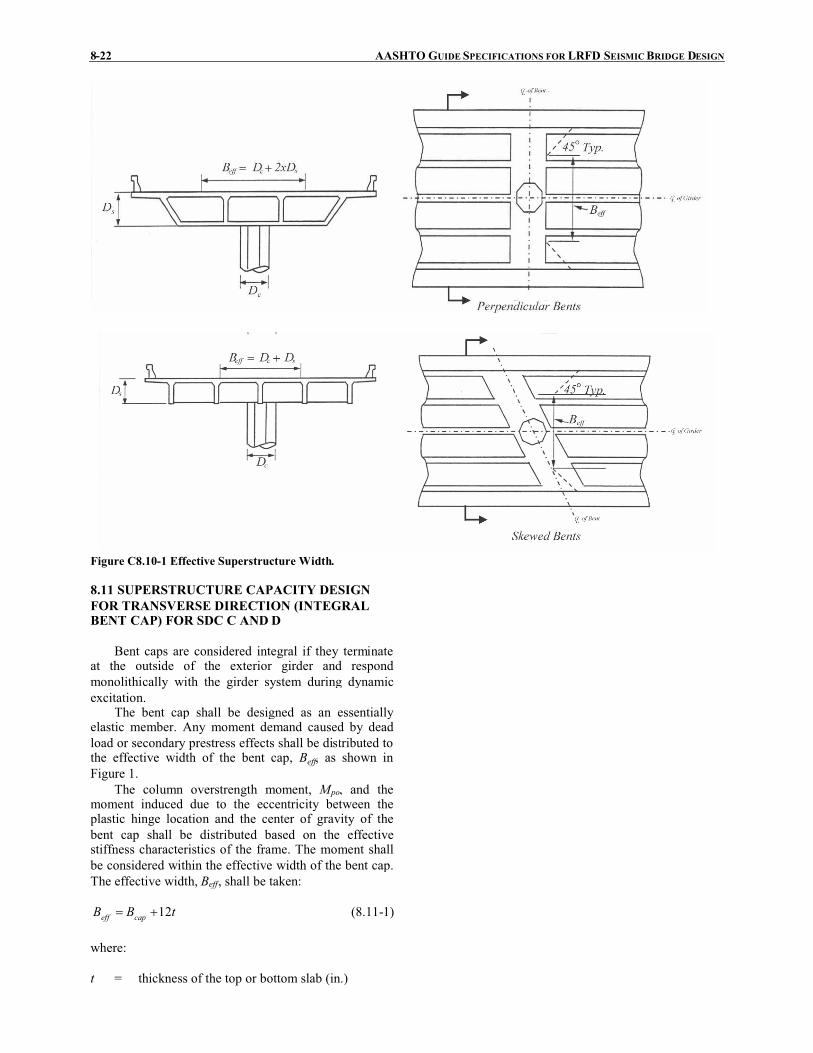
8-22 AASHTO GUIDE SPECIFICATIONS FOR LRFD SEISMICBRIDGE DESIGN
Figure C8.10-1 Effective Superstructure Width.
8.11 SUPERSTRUCTURE CAPACITY DESIGNFOR TRANSVERSE DIRECTION (INTEGRALBENT CAP) FOR SDC C ANDD
Bent caps are considered integral if they terminateat the outside of the exterior girder and respondmonolithically with the girder system during dynamicexcitation.
The bent cap shall be designed as an essentiallyelastic member. Any moment demand caused by deadload or secondary prestress effects shall be distributed tothe effective width of the bent cap, Beff, as shown inFigure 1.
The column overstrength moment, Mpo, and themoment induced due to the eccentricity between theplastic hinge location and the center of gravity of thebent cap shall be distributed based on the effectivestiffness characteristics of the frame. The moment shallbe considered within the effective width of the bent cap.The effective width, Beff, shall be taken:
tBB capeff 12�� (8.11-1)
where:
t = thickness of the top or bottom slab (in.)

SECTION 8: REINFORCED CONCRETE COMPONENTS 8-23
Bcap = thickness of the bent cap (in.)
Beff6 x ttop
6 x tbot
Ds
ttop
tbot
Bcap
Figure 8.11-1 Effective Bent Cap Width.
For SDC C and D, longitudinal flexural bent capbeam reinforcement shall be continuous. As aminimum, splicing of reinforcement shall beaccomplished using mechanical couplers capable ofdeveloping 125% of the expected yield strength, fye, ofthe reinforcing bars.
8.12 SUPERSTRUCTURE DESIGN FOR NON-INTEGRAL BENT CAPS FOR SDC C AND D
Non-integral bent caps shall satisfy all requirementsstated for frames with integral bent cap in the transversedirection.
For superstructure to substructure connections thatare not intended to fuse, a lateral force transfermechanism shall be provided at the interface that iscapable of transferring the maximum lateral forceassociated with plastic hinging of the ERS. Forsuperstructure to substructure connections that areintended to fuse, the minimum lateral force at theinterface shall be taken as 0.40 times the dead loadreaction plus the overstrength shear key(s) capacity, Vok .
Superstructure members supported on non-integralbent caps shall be simply supported at the bent cap orspan continuously with a separation detail such as anelastomeric pad or isolation bearing between the bentcap and the superstructure. Refer to Type 3 choice ofArticle 7.2.
Non-integral cap beams supporting superstructureswith expansion joints at the cap shall have sufficientsupport length to prevent unseating. The minimumsupport lengths for non-integral bent caps shall bedetermined based on Article 4.12. Continuity devicessuch as rigid restrainers or web plates are permissible tohelp ensure that unseating does not occur but shall notbe used in lieu of adequate bent cap width.
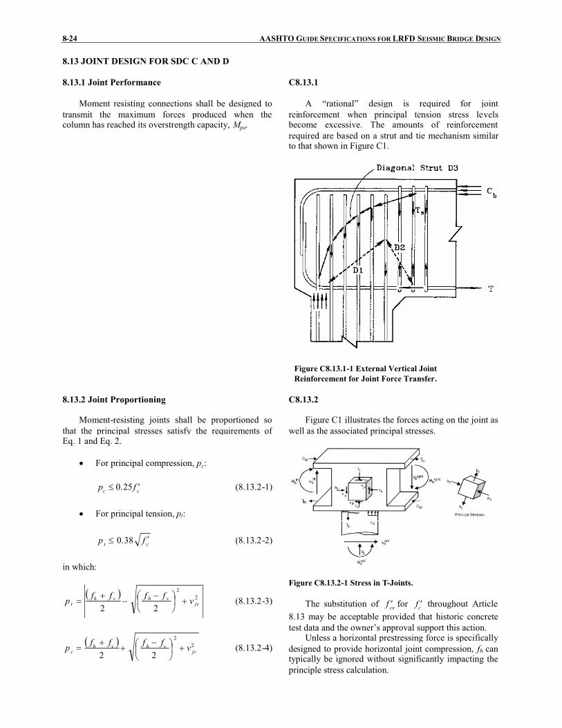
8-24 AASHTO GUIDE SPECIFICATIONS FOR LRFD SEISMICBRIDGE DESIGN
8.13 JOINT DESIGN FOR SDC C AND D
8.13.1 Joint Performance
Moment resisting connections shall be designed totransmit the maximum forces produced when thecolumn has reached its overstrength capacity, Mpo.
C8.13.1
A “rational” design is required for jointreinforcement when principal tension stress levelsbecome excessive. The amounts of reinforcementrequired are based on a strut and tie mechanism similarto that shown in Figure C1.
Figure C8.13.1-1 External Vertical JointReinforcement for Joint Force Transfer.
8.13.2 Joint Proportioning
Moment-resisting joints shall be proportioned sothat the principal stresses satisfy the requirements ofEq. 1 and Eq. 2.
� For principal compression, pc:
cc fp �� 25.0 (8.13.2-1)
� For principal tension, pt:
ct fp �� 38.0 (8.13.2-2)
in which:
� � 22
22 jvvhvh
t vffffp �����
�� ���� (8.13.2-3)
� � 22
22 jvvhvh
c vffffp �����
�� ���� (8.13.2-4)
C8.13.2
Figure C1 illustrates the forces acting on the joint aswell as the associated principal stresses.
Figure C8.13.2-1 Stress in T-Joints.
The substitution of cef � for cf � throughout Article8.13 may be acceptable provided that historic concretetest data and the owner’s approval support this action.
Unless a horizontal prestressing force is specificallydesigned to provide horizontal joint compression, fh cantypically be ignored without significantly impacting theprinciple stress calculation.

SECTION 8: REINFORCED CONCRETE COMPONENTS 8-25
jv
cjv A
Tv � (8.13.2-5)
capacjv BlA � (8.13.2-6)
jh
cv A
Pf � (8.13.2-7)
� � capscjh BDDA �� (8.13.2-8)
scap
bh DB
Pf � (8.13.2-9)
hM
T poc � (8.13.2-10)
where:
Bcap = bent cap width (in.)
Dc = cross sectional dimension of column in thedirection of bending (in.)
Ds = depth of superstructure at the bent cap forintegral joints or depth of cap beam for non-integral bent caps (in.)
lac = length of column reinforcement embedded intothe bent cap (in.)
Pc = column axial force including the effects ofoverturning (kip)
Pb = beam axial force at the center of the jointincluding the effects of prestressing and theshear associated with plastic hinging (kip)
h = distance from the center of gravity of thetensile force to the center of gravity of thecompressive force of the column section (in.)
Tc = column tensile force associated with thecolumn overstrength plastic hinging moment,Mpo (kip)
Mpo = overstrength plastic moment capacity ofcolumn determined in accordance with Article8.5 (kip-in.)
In lieu of Eq. 10, Tc may be obtained directly fromthe moment-curvature analysis.
8.13.3 Minimum Joint Shear Reinforcing
Transverse reinforcement in the form of tied

8-26 AASHTO GUIDE SPECIFICATIONS FOR LRFD SEISMICBRIDGE DESIGN
column reinforcement, spirals, hoops, or intersectingspirals or hoops shall be provided. The joint shearreinforcement may also be provided in the form ofcolumn transverse steel or exterior transversereinforcement continued into the bent cap.
Where the principal tension stress in the joint, pt, asspecified in Article 8.13.2 is less than '11.0 cf , thetransverse reinforcement in the joint, s, shall satisfy Eq.1 and no additional reinforcement within the joint isrequired.
yh
cs f
f '11.0� (8.13.3-1)
where:
fyh = nominal yield stress of transverse reinforcing(ksi)
'cf = nominal concrete compressive strength (ksi)
s = volumetric reinforcement ratio of transversereinforcing provided within the cap as definedby Eq. 8.6.2-6
Where the principal tension stress in the joint, pt, is
greater than '11.0 cf , then transverse reinforcement inthe joint, s, shall satisfy Eq. 2 and additional jointreinforcement is required as indicated in Article 8.13.4for integral bent cap beams or Article 8.13.5 for non-integral bent cap beams.
240.0
ac
sts l
A� (8.13.3-2)
where:
Ast = total area of column reinforcement anchored inthe joint (in.2)
lac = length of column reinforcement embedded intothe bent cap (in.)
For interlocking cores, s shall be based on the totalarea of reinforcement of each core.
8.13.4 Integral Bent Cap Joint Shear Design
8.13.4.1 Joint Description
The following types of joints are considered “T”joints for joint shear analysis:
� Integral interior joints of multi -column
C8.13.4.1
The design of beam-column joints is based uponresearch and experiments for circular columns framinginto rectangular beams. Although no specificrequirements have been developed for rectangular
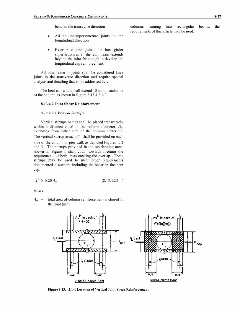
SECTION 8: REINFORCED CONCRETE COMPONENTS 8-27
bents in the transverse direction
� All column/superstructure joints in thelongitudinal direction
� Exterior column joints for box girdersuperstructures if the cap beam extendsbeyond the joint far enough to develop thelongitudinal cap reinforcement.
All other exterior joints shall be considered kneejoints in the transverse direction and require specialanalysis and detailing that is not addressed herein.
The bent cap width shall extend 12 in. on each sideof the column as shown in Figure 8.13.4.2.1-2.
columns framing into rectangular beams, therequirements of this article may be used.
8.13.4.2 Joint Shear Reinforcement
8.13.4.2.1 Vertical Stirrups
Vertical stirrups or ties shall be placed transverselywithin a distance equal to the column diameter, Dc,extending from either side of the column centerline.The vertical stirrup area, jv
sA shall be provided on eachside of the column or pier wall, as depicted Figures 1, 2and 3. The stirrups provided in the overlapping areasshown in Figure 1 shall count towards meeting therequirements of both areas creating the overlap. Thesestirrups may be used to meet other requirementsdocumented elsewhere including the shear in the bentcap.
stjvs AA 20.0� (8.13.4.2.1-1)
where:
Ast = total area of column reinforcement anchored inthe joint (in.2)
Figure 8.13.4.2.1-1 Location of Vertical Joint Shear Reinforcement.
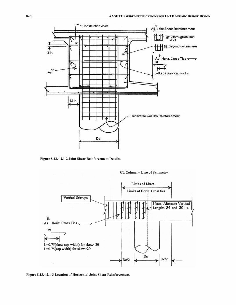
8-28 AASHTO GUIDE SPECIFICATIONS FOR LRFD SEISMICBRIDGE DESIGN
Figure 8.13.4.2.1-2 Joint Shear Reinforcement Details.
Figure 8.13.4.2.1-3 Location of Horizontal Joint Shear Reinforcement.

SECTION 8: REINFORCED CONCRETE COMPONENTS 8-29
8.13.4.2.2 Horizontal Stirrups
Horizontal stirrups or ties shall be placedtransversely around the vertical stirrups or ties in two ormore intermediate layers spaced vertically at not morethan 18 in. The horizontal reinforcement, jh
sA , shall beplaced within a distance Dc from each side of thecolumn centerline as shown in Figure 8.13.4.2.1-3.
stjhs AA 10.0� (8.13.4.2.2-1)
where:
Ast = total area of column reinforcement anchored inthe joint (in.2)
8.13.4.2.3 Horizontal Side Reinforcement
The total longitudinal side face reinforcement in thebent cap shall be at least equal to the greater of the areasspecified in Eq. 1 and shall be placed near the side facesof the bent cap with a maximum spacing of 12 in. asshown in Figure 8.13.4.2.1-2. Any side reinforcementplaced to meet other requirements shall count towardsmeeting the requirement of this article.
$.
$/
0
�botcap
topcap
sfs
A
AA
10.0
10.0max (8.13.4.2.3-1)
where:
sfsA = area of longitudinal side reinforcement in the
bent cap (in.2)
topcapA = area of bent cap top flexural steel (in.2)
botcapA = area of bent cap bottom flexural steel (in.2)
8.13.4.2.4 J-Bars
For integral cap of bents skewed greater than 20o,vertical J-bars hooked around the longitudinal top decksteel extending alternatively 24 in. and 30 in. into thebent cap shall be specified. The J-dowel reinforcementshall satisfy:
stbarj
s AA 08.0�� (8.13.4.2.4-1)
The J-bars shall be placed within a rectangularregion defined by the width of the bent cap and thedistance Dc on either side of the centerline of thecolumn, see Figure 1 and Figure 8.13.4.2.1-3.

8-30 AASHTO GUIDE SPECIFICATIONS FOR LRFD SEISMICBRIDGE DESIGN
Figure 8.13.4.2.4-1 Additional Joint Shear Steel for Skewed Bridges.
8.13.5 Non-Integral Bent Cap Joint Shear Design
Bent cap beams satisfying Eq. 1 shall be reinforcedin accordance with the requirements of Article 8.13.5.1.Bent cap beams not satisfying Eq. 1 shall be designedbased upon the strut and tie provisions of the AASHTOLRFD Bridge Design Specifications and as approved bythe owner.
cc DdD 25.1�� (8.13.5-1)
where:
Dc = column diameter (in.)
d = total depth of the bent cap beam (in.)
C8.13.5
Beam-column joints shall be designed toaccommodate the forces associated with the column’soverstrength plastic hinging moment capacity in anessentially elastic manner.
The design of non-integral bent cap bridge joints issummarized in Sritharan (2005).
8.13.5.1 Joint Shear Reinforcement
8.13.5.1.1 Vertical Stirrups Outside the JointRegion
Vertical stirrups with a total area, jvosA provided to
each side of the column shall satisfy:
stjvos AA 175.0� (8.13.5.1.1-1)

SECTION 8: REINFORCED CONCRETE COMPONENTS 8-31
where:
Ast = total area of column reinforcement anchored inthe joint (in2)
Vertical stirrups or ties shall be placed transverselywithin a distance equal to the column diameter, Dc,extending from each face of the column as shown inFigure 1 and Figure 2. The area of these stirrups shallnot be used to meet other requirements such as shear inthe bent cap.
Figure 8.13.5.1.1-1 Joint Shear Reinforcement Details.

8-32 AASHTO GUIDE SPECIFICATIONS FOR LRFD SEISMICBRIDGE DESIGN
Figure 8.13.5.1.1-2 Location of Vertical Joint Shear Reinforcement.
8.13.5.1.2 Vertical Stirrups Inside the Joint Region
Vertical stirrups with a total area, jvisA , spaced
evenly over the column shall satisfy:
stjvis AA 135.0� (8.13.5.1.2-1)
where:
Ast = total area of column reinforcement anchored inthe joint (in2)
8.13.5.1.3 Additional Longitudinal Cap BeamReinforcement
Longitudinal reinforcement, jlsA , in both the top
and bottom faces of the cap beam, shall be provided inaddition to that which is required to resist other loads.The additional area of the longitudinal steel shall satisfy:
stjls AA 245.0� (8.13.5.1.3-1)
where:
Ast = total area of column reinforcement anchored inthe joint (in2)
8.13.5.1.4 Horizontal J-Bars
Horizontal J-bars hooked around the longitudinalreinforcement on each face of the cap beam shall beprovided as shown in Figure 8.13.5.1.1-1. At aminimum, locate horizontal J-bars shall be located at

SECTION 8: REINFORCED CONCRETE COMPONENTS 8-33
every other vertical to longitudinal bar intersectionwithin the joint. The J-dowel reinforcement bar shall beat least a #4 size bar.
8.14 COLUMN FLARES FOR SDC C AND D
8.14.1 Horizontally Isolated Flares
The preferred method for detailing flares should beto horizontally isolate the top of flared sections from thesoffit of the cap beam which allows the flexural hinge toform at the top of the column, thus minimizing theseismic shear demand on the column.
A horizontal gap isolating the flare from the capbeam shall extend over the entire cross section of theflare excluding a core region equivalent to the prismaticcolumn cross section. For SDC C, a minimum gapthickness of 4 in. shall be used.
For SDC D the gap shall be large enough so that itwill not close during a seismic event. The gap thicknessshall be the largest of:
� 1.5 times the calculated plastic rotation demandfrom the pushover analysis times the distancefrom the center of the column to the extremeedge of the flare
� 4 in.
The added mass and stiffness of the isolated flaremay typically be ignored in the dynamic analysis.
8.14.2 Integral Column Flares
Column flares that are integrally connected to thebent cap should be avoided whenever possible. Lightlyreinforced integral flares should only be used whenrequired for service load design or aestheticconsiderations and are permitted for SDC A and B. Theflare geometry should be kept as slender as possible.
The higher plastic hinging forces shall beconsidered in the design of the column, superstructureand footing.
C8.14.2
Test results have shown that slender lightlyreinforced flares perform adequately after cracking hasdeveloped in the flare concrete, essentially separatingthe flare from the confined column core. However,integral flares require higher shear forces and momentsto form the plastic hinge at the top of the columncompared to isolated flares.
8.14.3 Flare Reinforcement
Column flares shall be nominally reinforced outsidethe confined column core to prevent the flare concretefrom completely separating from the column at highductility levels.
The reinforcement ratio for the transversereinforcement, outside of the column core, that confinesthe flared region shall be 0.0045 for the upper third ofthe flare and 0.00075 for the bottom two-thirds of theflare.
The minimum longitudinal reinforcement within theflare shall be equivalent to #5 bars at 12 in. spacing.
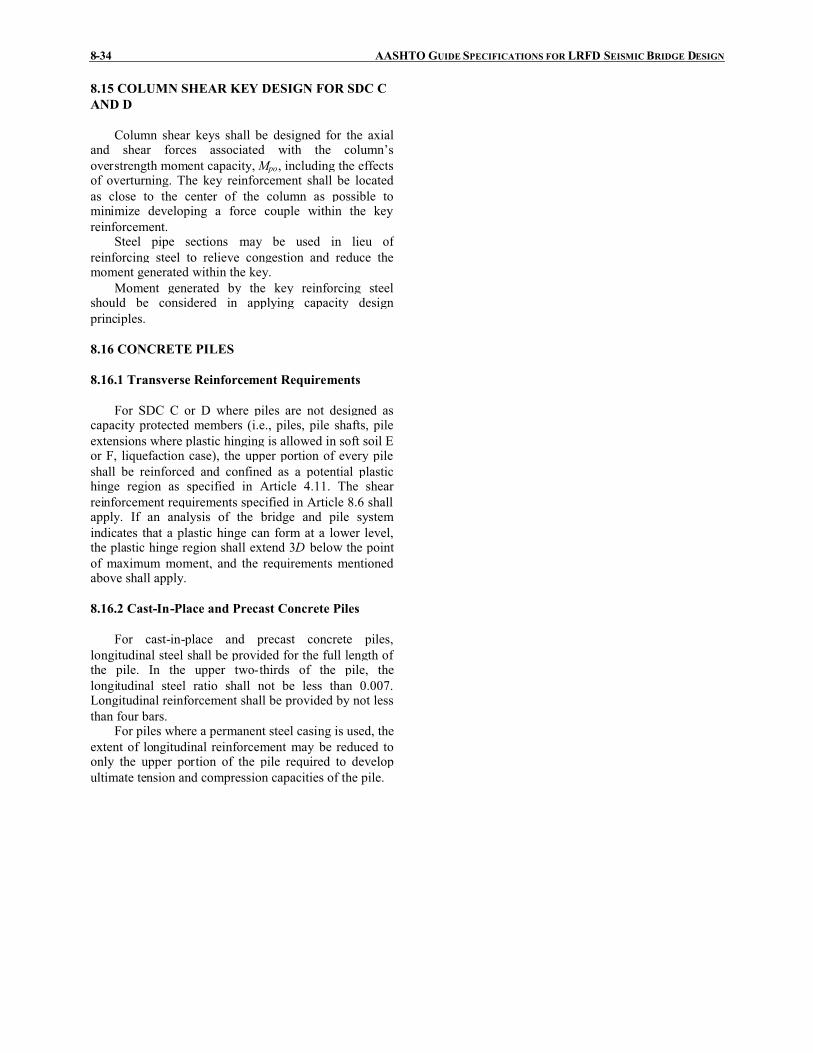
8-34 AASHTO GUIDE SPECIFICATIONS FOR LRFD SEISMICBRIDGE DESIGN
8.15 COLUMN SHEAR KEY DESIGN FOR SDC CAND D
Column shear keys shall be designed for the axialand shear forces associated with the column’soverstrength moment capacity,Mpo, including the effectsof overturning. The key reinforcement shall be locatedas close to the center of the column as possible tominimize developing a force couple within the keyreinforcement.
Steel pipe sections may be used in lieu ofreinforcing steel to relieve congestion and reduce themoment generated within the key.
Moment generated by the key reinforcing steelshould be considered in applying capacity designprinciples.
8.16 CONCRETE PILES
8.16.1 Transverse Reinforcement Requirements
For SDC C or D where piles are not designed ascapacity protected members (i.e., piles, pile shafts, pileextensions where plastic hinging is allowed in soft soil Eor F, liquefaction case), the upper portion of every pileshall be reinforced and confined as a potential plastichinge region as specified in Article 4.11. The shearreinforcement requirements specified in Article 8.6 shallapply. If an analysis of the bridge and pile systemindicates that a plastic hinge can form at a lower level,the plastic hinge region shall extend 3D below the pointof maximum moment, and the requirements mentionedabove shall apply.
8.16.2 Cast-In-Place and Precast Concrete Piles
For cast-in-place and precast concrete piles,longitudinal steel shall be provided for the full length ofthe pile. In the upper two-thirds of the pile, thelongitudinal steel ratio shall not be less than 0.007.Longitudinal reinforcement shall be provided by not lessthan four bars.
For piles where a permanent steel casing is used, theextent of longitudinal reinforcement may be reduced toonly the upper portion of the pile required to developultimate tension and compression capacities of the pile.

REFERENCES R-1
REFERENCES
AASHTO, 1999,Guide Specifications for Seismic Isolation Design . 2nd Edition. Washington, DC: AmericanAssociation of State Highway and Transportation Officials.
AASHTO. 2002. Standard Specifications for Highway Bridges and Interim Specifications,17thEdition, HB-17. AmericanAssociation of State Highway and Transportation Officials, Washington, DC.
AASHTO. 2004. LRFD Bridge Design Specifications and Interim Specifications. 3rd Edition, LRFDUS-3-I2. AmericanAssociation of State Highway and Transportation Officials, Washington, DC.
AASHTO. 2007.LRFD Bridge Design Specifications, 4th Ed., AmericanAssociation of State Highway and TransportationOfficials, Washington, DC.
AASHTO/AWSD1.5M/D1.5. 2002. Bridge Welding Code.American National Standard/American Association of StateHighway and Transportation Officials/American Welding Society, Washington, DC.
Abrahamson, N.A., 1992, “Non-stationary Spectral Matching Program,” Seismological Research Letters,v. 63, no.1, p.30.
AISC. 1992. Seismic Provisions for Structural Steel Buildings. American Institute of Steel Construction, Chicago, IL.
AISC. 1993. Load and Resistance Factor Design Specification for Structural Steel Buildings. 2nd Edition. AmericanInstitute of Steel Construction, Chicago, IL.
AISC. 1994.Manual of Steel Construction - Load and Resistance Factor Design. 2nd Edition. American Institute of SteelConstruction, Chicago, IL.
AISC. 1997. Seismic Provisions for Structural Steel Building. American Institute of Steel Construction, Chicago, IL.
AISC. (1999b). Seismic Provisions for Structural Steel Buildings (2005) Supplement No. 1American Institute of Steel Construction, Chicago, IL.
Alfawahkiri, F., 1997, Cyclic Testing of Concrete-Filled Circular Tubes, Thesis presented in partial fulfillment for thedegree of Master of Applied Sciences, Dept. of civil Engineering, University of Ottawa, Ottawa, Ontario, Canada.
Applied Technology Council (ATC). 1996. Improved Seismic Design Criteria for California Bridges: ProvisionalRecommendations. Report ATC-32, Redwood City, CA
Aschheim, M., and J. P. Moehle. Shear Strength and Deformability of RC Bridge Columns Subjected to Inelastic CyclicDisplacements.Report UCB/EERC 92/04, Earthquake Engineering Research Center, University of California, Berkeley,CA, March 1992.
Astaneh, A. A., Goel, S. C., and Hanson, R. D. (1986). "Earthquake-resistant Design of DoubleAngle Bracings," Engineering Journal, AISC, 23(4).
Astaneh-Asl, A., Shen, J.H., and Cho, S.W., 1993, “Seismic Performance and Design Consideration in Steel Bridges”,Proceedings of the 1st US Seminar on Seismic Evaluation and Retrofit of Steel Bridges, San Francisco, California.
Astaneh-Asl, A., Bolt, B., Mcmullin, K.M., Donikian, R. R., Modjtahedi, D., and Cho, S. W., 1994,Seismic Performanceof Steel Bridges During the 1994 Northridge Earthquake, UCB report CE-STEEL 94/01, University of California atBerkeley.
Astaneh-Asl, A., and Roberts, J., 1996, Proceedings of the 2nd US Seminar on Seismic Evaluation and Retrofit of SteelBridges, San Francisco, Report No. UCB/CEE-Steel-96/09, Department of Civil and Environmental Engineering,University of California at Berkeley.

R-2 AASHTO GUIDE SPECIFICATIONS FOR LRFDSEISMIC BRIDGE DESIGN
Astaneh, A. A. (1998). "Seismic Behavior and Design of Gusset Plate," Steel Tips, Structural SteelEducation Council, Moraga, CA.
ATC, 1981, Seismic Design Guidelines for Highway Bridges, ATC-6 Report, Applied Technology council, RedwoodCity,California.
ATC, 1993, Proceedings of Seminar on Seismic Isolation, Passive Energy Dissipation, and Active Control, ATC-17-1Report, Applied Technology Council, Redwood City, California.
ATC and BSSC, 1997, Applied Technology Council and Building Seismic Safety Council, NEHRP Guidelins for theSeismic Rehabilitation of Buildings, Federal Emergency Management Agency Report FEMA-273.
Azizinamini, A., Shahrooz, B., El-Remaily, A., and Astaneh, H., 1999, “Chapter 10: Connections to CompositeMembers,”Handbook of structural Steel Connection Design and Details, McGraw-Hill, New York.
Ballard, T. A., Krimotat, A., Mutobe, R., and Treyger, S., 1996, “Non-linear Seismic Analysis of Carquinez Strait bridge,”Proceedings of the 2nd U.S. Seminar on Seismic Design, Evaluation and Retrofit of Steel Bridges, San Francisco, ReportNo. UCB/CEE-Steel-96/09, Department of Civil Engineering, University of California, Berkeley, pp. 359-368.
Berry, M. and M. O. Eberhrnd. Estimating Flexural Damage in Reinforced Concrete Columns. Pacific EarthquakeEngineering Research Center (PEER), University of California, Berkeley, CA August 2003.
Billings, I.J., Kennedy, D.W., Beamish, M.J., Jury, R., Marsh, J., 1996, “Auckland Harbour Bridge SeismicAssessment”,Proceedings of the 2nd U.S. Seminar on Seismic Design, Evaluation and Retrofit of Steel Bridges, San Francisco, ReportNo. UCB/CEE-Steel-96/09, Department of Civil Engineering, University of California, Berkeley, pp. 275-293.
Bolt, B.A., and Gregor, N.J., 1993, Synthesized Strong Ground Motions for the Seismic Condition Assessment of theEastern Portion of the San Francisco Bay Bridge, Earthquake Engineering Research Center, Berkeley, ReportUCB/EERC-93.12, University of California at Berkeley.
BSSC, 1995, 1994 Edition NEHRP Recommended Provisions for Seismic Regulations for New Buildings, ReportsFEMA-222a and FEMA-223A, prepared by the Building Seismic Safety Council for the Federal EmergencyManagement Agency, Washington, D.C.
BSSC, 1998, 1997 Edition NEHRP Recommended Provisions for Seismic Regulations for New Buildings and OtherStructures, FEMA-302 and FEMA-303 Reports, prepared by the Building Seismic Safety Council for the FederalEmergency Management Agency, Washington, D.C.
Bruneau, M., Wilson, J.W., and Tremblay, R. 1996, “Performance of Steel Bridges During the 1995 Hyogoken-Nanbu(Kobe, Japan) Earthquake”, Canadian Journal of Civil Engineering, Vol. 23, No. 3, pp. 678-713.
Bruneau, M., Uang., C.M., and Whittaker, A, 1997, Ductile Design of Steel Structures, McGraw-Hill, New York, NY,480 pages.
Bruneau, M., andMarson, J., 1999, Cyclic Testing of Concrete-Filled Circular Steel Tube Bridge ColumnHaving EncasedFixed Based Detail, Report OCEERC-99-22, Ottawa Carleton Earthquake EngineeringResearchCentre, Ottawa, Ontario,Canada.
Buckle, I.G., Mayes, R.L., and Button, M.R., 1987, Seismic Design and Retrofit Manual for Highway Bridges, ReportFHWA-IP-87-6, Federal Highway Administration, Washington, D.C., 312 pp.
Button, M.R., Cronin, C.J., and Mayes, R.L., 1999, Effect of Vertical Ground Motions on the Structural Response ofHighway Bridges, Technical Report MCEER-99-0007, State University of New York at Buffalo.
Caltrans. (1995a). Bridge Memo to Designers Manual, California Department of Transportation, Sacramento, CA.
Caltrans. (1995b). Bridge Design Aids Manual, California Department of Transportation,Sacramento, CA.

REFERENCES R-3
Caltrans. (1997). San Francisco-Oakland Bay Bridge West Spans Seismic Retrofit Design Criteria, Final Draft,California Department of Transportation, Sacramento, CA.
Caltrans. (1999).Memo to Designers 20-1 Seismic Design Methodology, California Department of Transportation,Sacramento, CA.
Caltrans. (2000a). Bridge Design Specifications, California Department of Transportation,Sacramento, CA.
Caltrans. 2001. Guide Specifications for Seismic Design of Steel Bridges. 1st Edition. California Department ofTransportation, Sacramento, CA, December 2001.
Caltrans. (2006). Seismic Design Criteria Version 1.4. California Department of Transportation, Sacramento, CA,December.
Carden, L., Garcia-Alvarez, S., Itani, A, and Buckle, I. (2001). “Cyclic Response of Steel Plate Girder Bridges in theTransverse Direction,” The Sixth Caltrans Seismic Research Workshop, Divisions of Engineering Services, CaliforniaDepartment of Transportation, Sacramento, CA, June 12-13.
Chang, G.A. and Mander, J.B., 1994a, Seismic Energy Based Fatigue Damage Analysis of Bridge Columns: Part I –Evaluation of Seismic Capacity, Technical Report NCEER-94-0006, National Center for Earthquake EngineeringResearch, State University of New York at Buffalo, New York.
Chang, G.A. and Mander, J.B., 1994b, Seismic Energy Based Fatigue Damage Analysis of Bridge Columns: Part II –Evaluation of Seismic Demand, Technical Report NCEER-94-0013, National Center for Earthquake EngineeringResearch, State University of New York at Buffalo, New York.
CSA, 2001, Limit States Design of Steel Strucutres,Canadian Standards Association, Rexdale, Ontario, Canada.
CSABAC, 1999, Seismic Soil-Foundation-Structure Interaction, Final report, Caltrans Seismic Advisory Board Ad HocCommittee on Soil-Foundation-Structure Interaction (CSABAC), prepared for California Department of Transportation,Sacramento, California.
Dameron, R. A., Sobash, V. P., and Parker, D. R., 1995, Seismic Analysis of the Existing SanDiego-Coronado Bay Bridge,Report prepared for the California Department of Transportation, Anatech Consulting Engineers, 800 pages.
DesRoches, R., and G. Fenves. New design and analysis procedures for intermediate hinges in multiple-frame bridges.Report UCB/EERC 97/12, Earthquake Engineering Research Center, University of California, Berkeley, CA 1997.
Dicleli, M., and Bruneau, M., 1995a, “Seismic Performance of Multispan Simply Supported Slab-on-Girder HighwayBridges,” Engineering Structures , Vol. 17, No. 1, pp. 4-14.
Dicleli, M., and Bruneau, M., 1995b, “Seismic Performance of Simply Supported and Continuous Slab-on-Girder SteelBridges,” Structural Journal of the American Society of Civil Engineers, Vol. 121, No. 10, pp. 1497-1506.
Dietrich, A. M., and Itani, A. M., 1999,Cyclic Behavior of Laced and PerforatedMembers on the San Francisco-OaklandBay Bridge, Center for Civil Engineering Earthquake Research, Report No. CCER-99-09, University ofNevada, Reno, 194pp.
Donikian, R., Luo, S., Alhuraibi, M., Coke, C., Williams, M., and Swatta, M., 1996, “The Global Analysis Strategy for theSeismic Retrofit Design of the San Rafael and San Mateo Bridges”, Proceedings of the 2nd U. S. Seminar on SeismicDesign, Evaluation and Retrofit of Steel Bridges, Report No. UCB/CEE-Steel-96/09, Department of Civil andEnvironmental Engineering, University of California at Berkeley, pp. 405-415.
EERI, 1990, “Loma Prieta Earthquake Reconnaissance Report,” Earthquake Spectra, Supplement to Vol. 6, EarthquakeEngineering Research Institute, Oakland California.

R-4 AASHTO GUIDE SPECIFICATIONS FOR LRFDSEISMIC BRIDGE DESIGN
Frankel, A., C. Mueller, T. Barnhard, D. Perkins, E. V. Leyendecker, N. Dickman, S. Hanson, and M. Hopper (1996).Interim National Seismic Hazard Maps: Documentation. U.S. Geological Survey, January 1996.
Gasparini, D., and Vanmarcke, E. H., 1976, SMIQKE: A Program for Artificial Motion Generation, Department of CivilEngineering, Massachusetts Institute of Technology, Cambridge, MA.
Gates et al., 1995,Proceedings of the First National Seismic Conference on Bridges and Highways, SanDiego, California.
Housner, G.W. (Chairman, Seismic Advisory Board), 1994 “The Continuing Challenge,” Report to theDirector, California Department of Transportation on the 1994 Northridge Earthquake, Seismic AdvisoryBoard, Sacramento, California.
ICBO, 1997, Uniform Building Code, International Conference of Building Officials, Whittier, California.
ICC, 2000, International Building Code, International Code Council, Inc., Birmingham, Alabama.
Imbsen, R., Davis, F. V., Chang, G. S., Pecchia, D., and Liu, W. D., 1997, “Seismic Retrofit of I-40 Mississippi RiverBridges”, Proceedings of National Seismic Conference on Bridges and Highways-Progress in Research and Practice,Sacramento, California, pp. 457-469.
Ingham, T. J., Rodriguez, S., Nader, M. N., Taucer, F., and Seim, C., 1996, “Seismic Retrofit of the Golden Gate Bridge”,Proceedings of the 2ndU. S. Seminar on Seismic Design, Evaluation and Retrofit of Steel Bridges, Report No. UCB/CEE-Steel-96/09, Department of Civil and Environmental Engineering, University of California at Berkeley, pp. 145-164.
Itani, A. M. (1997). "Cyclic Behavior of Richmond-San Rafael Tower Links," Report No. CCEER 99-4, Center forCivil Engineering Earthquake Research, University of Nevada, Reno, NV
Itani, A. M., Vesco, T. D. and Dietrich, A M. (1998). "Cyclic Behavior of As-Built Laced Members with End GussetPlates on the San Francisco-Oakland Bay Bridge," Report No. CCEER 98-01, Center for Civil EngineeringEarthquake Research, University of Nevada, Reno, NV.
Itani, A. M. and Sedarat, H. (2000). “Seismic Analysis and Design of the AISI LRFD Design Examples of SteelHighway Bridges,” Report No. CEER 00-8, Center for Civil Engineering Earthquake Research, University of Nevada,Reno, NV.
Jones, M. H., Holloway, L. J., Toan, V., and Hinman, J., 1997, “Seismic Retrofit of the 1927 Carquinez Bridge by aDisplacement Capacity Approach”, Proceedings of the National Seismic Conference on Bridges and Highways-Progress in Research and Practice, Sacramento, California, pp. 445-456.
Kompfner, T. A., Tognoli, J. W., Dameron, R. A., and Lam, I. P., 1996, “The San Diego-Coronado Bay BridgeSeismic Retrofit Project”, Proceedings of the 2nd U. S. Seminar on Seismic Evaluation and Retrofit of Steel Bridges,Report No. UCB/CEE-Steel-96/09, Department of Civil and Environmental Engineering, University of California atBerkeley, pp. 73-93.
Kramer, S. L., 1996, Geotechnical Earthquake Engineering, Prentice Hall, New Jersey.
Lam, I. P., Kapuska, M., Chaudhuri, D., 1998, Modeling of Pile Footing and Drilled Shafts for Seismic Design,Technical Report MCEER-98-0018, Multidisciplinary Center for Earthquake Engineering Research, State Universityof New York at Buffalo, New Your, 117 pp.
Lilihanand, K., and Tseng, W. S., 1988, “Development and Application of Realistic Earthquake Time-HistoriesCompatible with Multiple-Damping Design Spectra,” Proceedings of the 9th World Conference on EarthquakeEngineering, Tokyo-Kyoto: Japan Association for Earthquake Disaster Prevention.
Mander, J.B., M.J.N. Priestley, and R. Park, "Theoretical Stress-Strain Model for Confined Concrete", Journal of theStructural Division, ASCE, Vol. 114, No. 8, August 1988, pp. 1804-1826.

REFERENCES R-5
Mander, J.B., M.J.N. Priestley, and R. Park, "Observed Stress-Strain Behavior of Confined Concrete", Journal of theStructural Division, ASCE, Vol. 114, No. 8, August 1988, pp. 1827-1849.
Mander, J. B., Panthaki, F. D., and Kasalanati, A., 1994, “Low-Cycle Fatigue Behavior of Reinforcing Steel”, ASCEJournal of Materials in Civil Engineering, Vol. 6, No. 4, Nov. 1994, Paper No. 6782, pp. 453-468.
Mander, J. B., and Cheng, C-T., 1999, “Replaceable Hinge Detailing for Bridge Columns,” Seismic Response of ConcreteBridges, American Concrete Institute, Special Publication SP-187.
Maroney, B., 1996, “Seismic Retrofit of the East Spans of the San Francisco-Oakland BayBridge,”Proceedings of the 2nd
U. S. Seminar on Seismic Evaluation and Retrofit of Steel Bridges, Report No. UCB/CEE-Steel-96/09, Department of Civiland Environmental Engineering, University of California at Berkeley, pp. 17-34.
Martin, G. R., ed., 1994, Proceedings of the 1992 NCEER/SEAOC/BSSCWorkshop on Site ResponseDuring Earthquakesand Seismic Code Provisions, University of Southern California, LosAngeles, November 18-20, 1992, National Center forEarthquake Engineering Research Special Publication NCEER-94-SP01, Buffalo, New York.
Martin, G. R. and R. Dobry, 1994 “Earthquake Site Response and Seismic Code Provisions”, NCEER Bulletin,vol. 8, no. 4, National Center for Earthquake Engineering Research, Buffalo, New York.
Martin, G. R., 1998,Development of Liquefaction Mitigation Methodologies: Ground Densification Methods, NationalCenter for Earthquake Engineering Research, Technical Report, Buffalo, New York.
McCallen, D. B., and Astaneh-Asl, A., 1996, “Seismic Response of Steel Suspension Bridge,” Proceedings of the 2nd U. S.Seminar on Seismic Evaluation and Retrofit of Steel Bridges, Report No. UCB/CEE-Steel-96/09, Department of Civil andEnvironmental Engineering, University of California at Berkeley, pp. 335-347.
Miranda, E. and Bertero, V., 1994, “Evaluation of Strength Reduction Factors for Earthquake-Resistant Design,”Earthquake Spectra, Vol. 10, No. 2, Earthquake Engineering Research Institute, Oakland, California.
NCHRP 12-49 (2001). Recommended LRFD Guidelines for the Seismic Design of HighwayBridges, Part I: Specifications and Part II: Commentary and Appendixes, NCHRP 12-49 Project Team, MCEER, StateUniversity of New York at Buffalo, Buffalo, NY.
Popov, E. P., Bertero, V. V., and Chandramouli, S., 1975,Hysteretic Behavior of Steel Columns, Earthquake EngineeringResearch Center Report UCB/EERC-75-11, University of California, Berkeley.
Popov, E. P. and Tsai, K. C. (1989). "Performance of Large Seismic Steel Moment Connectionsunder Cyclic Loads," Engrg. J., AISC, 26(2), pp. 51-60.
Priestley, M.J.N., and F. Seible, “Seismic Assessment and Retrofit of Bridges”, Structural Systems ResearchProject, Report SSRP-91/03, University of California San Diego, July 1991.
Preistly, M. J. N., F. Seible, and G. M. Calvi. Seismic Design and Retrofit of Bridges. John Wiley and Sons, New York,NY 1996.
Prucz, Z., Conway, W. B., Schade, J. E., and Ouyang, Y., 1997, “Seismic Retrofit Concepts and Details for Long-SpanSteel Bridges”, Proceedings of National Seismic Conference on Bridges and Highways-Progress in Research andPractice, Sacramento, California, pp. 435-444.
Rinne, E.E., 1994, “Development of New Site Coefficient of Building Codes,” Proceedings of the Fifth U.S.National Conference on Earthquake Engineering, Vol. III, pp.69-78, Earthquake Engineering ResearchInstitute, Oakland, California.
Roberts, J.E., 1992, “Sharing California’s Seismic Lessons”,Modern Steel Constructions, pp. 32-37.

R-6 AASHTO GUIDE SPECIFICATIONS FOR LRFDSEISMIC BRIDGE DESIGN
Rodriguez, S., and Ingham, T.J., 1996, “Nonlinear Dynamic Analysis of the Golden Gate Bridge”, Proceeding of the 2nd
US Seminar on Seismic Evaluation and Retrofit of Steel Bridges, Report No. UCB/CEE-Steel-96/09, Department of Civiland Environmental Engineering, University of California at Berkeley, pp. 457-466.
SAC, 1995, Interim Guidelines: Evaluation, Repair, Modification and Design of Welded Steel Moment FrameStructures, prepared by the SAC Joint Venture, a partnership of the Structural Engineers Association of California, theApplied Technology Council, and California Universities for Research in Earthquake Engineering, published by theFederal Emergency Management Agency, (FEMA-267 Report), Washington, D.C.
SAC, 1997, Interim Guidelines Advisory No. 1 – Supplement to FEMA-267, prepared by the SAC Joint Venture, apartnership of the Structural Engineers Association of California, the Applied Technology Council, and CaliforniaUniversities for Research in Earthquake Engineering, published by the Federal Emergency Management Agency,(FEMA-267A Report), Washington, D.C.
SAC, 2000, Recommended Seismic Design Criteria for New Steel Moment-Frame Buildings, prepared by the SACJoint Venture, a partnership of the Structural Engineers Association of California, the Applied Technology Council,and California Universities for Research in Earthquake Engineering, published by the Federal Emergency ManagementAgency, (FEMA-350 Report), Washington, D.C.
Schamber, R.A., Li, F., Fuller, R.T., and Liu, W.D., 1997, “Seismic Resistance of Steel Bascule Bridges”,Proceedings of National Seismic Conference on Bridges and Highways – Progress in Research and Practice,Sacramento, California, pp. 381-394.
Schneider, S.P., Roeder, C.W., and Carpenter, J.E., 1992, “Seismic Behavior of Moment-Resisting Steel Frames:Experimental Study”, ASCE Structural Journal, Vol. 119, No. 6; pp. 1885-1902.
Seim, C., Ingham, T. and Rodriguez, S., 1993, “Seismic Performance and Retrofit of theGoldenGate bridge”,Proceedingsof the 1st US Seminar on Seismic Evaluation and Retrofit of Steel Bridges, San Francisco, California.
Sharma, A.A., Mander, J.B., Blabac, B.B., and Chen, S.S., 2001, Experimental Investigation and Retrofit of Steel PileFoundations and Pile Bents Under Cyclic Lateral Loading, Technical Report, Multidisciplinary Center for EarthquakeEngineering Research, University at Buffalo, Buffalo, New York.
Sherman, D.R., 1976, Tentative Criteria For Structural Applications Of Steel Tubing and Pipe, American Iron andSteel Institute, Washington, D.C.
Shinozuka, M., Saxena, V., and Deodatis, G., 1999, Effect of Spatial Variation of Ground Motion on HighwayStructures, Draft Final Report for MCEER Higheay Project, Submitted to Multidisciplinary Center for EarthquakeEngineering Research, University at Buffalo, Buffalo, New York.
Shirolé, A. M., andMalik, A. H., 1993, “Seismic Retrofitting of Bridges in NewYork State”, Proceedings, Symposium onPractical Solutions for Bridge Strengthening & Rehabilitation, Iowa State Univ., Ames, Iowa, pp. 123-131.
Silva, W., and Lee, K., 1987, “State-of-the-Art for Assessing Earthquake Hazards in the United State: Report 24,”WESRASCAL Code for Synthesizing Earthquake Ground Motions, Miscellaneous Paper 5-73-1, U. S. Army EngineerWaterways Experiment Station, Vicksburg, Mississippi.
Silva, W., 1997, “Characteristics of Vertical Strong GroundMotions for Applications to EngineeringDesign,Proceedingsof the FHWA/NCEER Workshop on the National Representation of Seismic Ground Motions for New and ExistingHighway Facilities, National Center for Earthquake EngineeringResearch, Buffalo, NewYork, Technical Report NCEER-97-0010, State University of New York at Buffalo, pp. 205-252.
Somerville, P.G., 1997, “The Characteristics and Quantification of Near Fault Ground Motion,” Proceedings of theFHWA/NCEER Workshop on the National Representation of Seismic Ground Motion for New and Existing HighwayFacilities, Center for Earthquake engineering Research, Buffalo, NewYork, Technical Report 97-0010, State University ofNew York at Buffalo, pp. 1293-1318.

REFERENCES R-7
Somerville, P. G., Smith, N. G., Graves, R.W., and Abrahamson, N. A., 1997, “Modification of Empirical StrongGroundMotion Attenuation Relations to Include the Amplitude and Duration Effects of Rupture Directivity,” SeismologicalResearch Letters, Vol. 68, pp. 199-222.
Somerville, P., Krawinkler, H., and Alavi, B., 1999, Development of ImprovedGroundMotion Representation andDesignProcedures for Near-Fault Ground Motion, prepared for California Strong Motion Instrumentation Program, CaliforniaDivision of Mines and Geology, Sacramento, California, Draft.
South Carolina Department of Transportation. Seismic Design Specifications forHighway Bridges.1st. Edition. 2001, withOctober 2002 Interim Revisions.
Sritharan, S., "Improved Seismic Design Procedure for Concrete Bridge Joints", Journal of the Structural Engineering,ASCE, Vol. 131, No. 9, September 2005, pp. 1334-1344.
Tang, X. and Goel, S. C., 1987, Seismic Analysis and Design Considerations of Braced Steel Structures, Report No.UMCE 87-4, Department of Civil Engineering, University of Michigan, Ann Arbor, Michigan.
Uang, C. M., and Bertero, V. V., 1986, Earthquake Simulation Tests and Associated Studies of a 0.3-ScaleModel of a Six-Story Concentrically Braced Steel Structure, Report No. UCB/EERC-86/10, Earthquake Engineering Research Center,University of California, Berkeley.
Uang, C. M., Tsai, K. C., and Bruneau, M., 2000, “Seismic Design of Steel Bridges”,Bridge EngineeringHandbook, (Ed.W.F. Chen, L. Duan), CRC Press, Boca Raton, Florida, pp. 39-1 to 39-34.
Uang, C. M., Bruneau, M., Whittaker, A. S., and Tsai, K. C., 2001, “Seismic Design of Steel Structures,” Seismic DesignHandbook, (Ed. Naeim), Kluwer Academic Publishers, Norwell, Massachusetts, pp. 409-462.
U. S. Army Corp of Engineers, 2000, Time History Dynamic Analysis of Concrete Hydraulic Structures, USACEEngineering Circular EC1110-2-6051.
Vincent, J., Abrahamson, T., O’Sullivan, M., Lim, K., Dameron, R., and Donikian, R., 1997, “Analysis andDesign for theInelastic Response of a Major Steel Bridge,” Proceedings of the 2nd National Conference on Bridges and Highways,Sacramento, California, pp. 541-555.
Whitmore, R. E. (1952). "Experimental Investigation of Stresses in Gusset Plates," Bulletin 16, University ofTennessee, Knoxville, TN.
Zahrai, S. M. and Bruneau, M. (1998). "Impact of Diaphragms on Seismic Responses of Straight Slab-on-Girder SteelBridges," J. Struct. Engrg. 124(8), pp. 938-947.
Zahrai, S. M. and Bruneau, M. (1999). "Ductile End-Diaphragms for Seismic Retrofit of Slab-on-Girder SteelBridges," J. Struct. Engrg. 125(1), pp. 71-80.

APPENDIX A: FOUNDATIONROCKING ANALYSIS A-1
APPENDIXA
FOUNDATION ROCKING ANALYSIS
Design a strategy based on transient foundation uplift, or Foundation Rocking, involving separation of the foundationfrom the subsoil, may be permitted under seismic loading, provided that foundation soils are not susceptible to loss ofstrength under the imposed cyclic loading. The displacement, or drift �T ,as shown in Figure A1, shall be calculated basedon the flexibility of the column in addition to the effect of the footing rocking mechanism. For multi-column bents withmonolithic connections to the substructure, the effect of rocking shall be examined on the overturning and framingconfiguration of the subject bent.
For the longitudinal response, multi-column bents that are not monolithic to the superstructure shall be treated similarto a single column bent.
Rocking displacement demands shall be calculated with due consideration of the dynamics of the bridge system orframe. The tributary inertial weight and articulation and/or restraint of other elements of the frame shall be incorporatedinto the analysis. Some adjustment of the following equations, which were derived for an individual single-column bent,may be required.
For the case of a single column bent or a multi-column bent without a monolithic connection to the superstructure, thefooting should be considered to be supported on a rigid perfectly plastic soil with uniform compressive capacity pb . Theoverturning and rocking on the foundation maybe simplified using a linear force-deflection relationship as outlined in thefollowing procedure:
� Guess the displacement �� ��� ���������������������� ��esponding to a fixed base analysis.
� Calculate the applied force F at the superstructure level based on Rocking Equilibrium shown in Figure A1.
From Statics:
rs
r
FT H
WHaLWF ����
2)( (A-1)
in which:
)( br
T
pBW
a � (A-2)
� Calculate the equivalent system stiffness:
��F
K r (A-3)
� Calculate the period “T” of the bent system based onKr and Ws.
� Recalculate ��� ����ring 10% damping; this would typically reduce the spectral acceleration ordinates Sa of a5% damped spectrum by approximately 20%.
)8.0(4 2
2
aST
���
����
�
"�� (A-4)
where:
������������� ������ ���������ement on top of the column (ft.)
Sa is the spectral acceleration (ft./sec.2 )
� Iterate until convergence, otherwise the bent is shown to be unstable.

A-2 AASHTO GUIDE SPECIFICATIONS FOR LRFDSEISMIC BRIDGE DESIGN
� Once a converging solution is reached, the local ductility term � can be calculated in order to ensure the columnadequacy where rocking mechanism is not mobilized.
ycol��
� (A-5)
where:
�ycol = column idealized yield displacement
For soil cover greater than 3 ft., the effect of soil passive resistance should be included in the rocking equilibrium offorces.
The design of a column on spread footing system shall follow the steps identified on the flowchart shown on FigureA2.
The restoring moment Mr shall be calculated as follows:
���
����
� ��
2aL
WM FTr (A-6)
For the case where,Mo � 1.5Mr, the column shear capacity shall be determined based on Article 8.6 following SDCBrequirements. The column shear demand shall be determined based on 1.5Mr moment demand.
For the case where,Mr �Mo, forces based on column plastic hinging shall be considered; the column shear capacityshall be determined based on Article 8.6 following SDCD requirements. For all other cases, the column shall be designedforP-���equirements based on rocking analysis as well as column plastic hinging shear capacity requirements considering afixed based analysis and following Article 8.6 SDC C requirements.
The shear component of loading should not be included during the overturning check; i.e., a de-coupled approachshould be used in treating the two loads. Experience has shown that combining the horizontal load and moment insimplified bearing capacity equations can result in unreasonably sized footings for seismic loading.
Unfactored resistance shall be used for the moment capacity check for two reasons: (1) the potential for the designseismic load is very small, and (2) the peak load will occur for only a short duration. The distribution and magnitude ofbearing stress, as well as liftoff of the footing, are limited to control settlement of the footing from the cycles of load.
Non-triangular stress distributions or greater than 50% liftoff may be used if analysis can show that soil settlementfrom cyclic shakedown does not exceed amounts that result in damage to the bridge or unacceptable movement of theroadway surface. By limiting stress distribution and the liftoff to the specified criteria, the amount of shakedown willnormally be small under normal seismic loading conditions.
This work was derived based on that presented by Priestley et al. (1996).

APPENDIX A: FOUNDATIONROCKING ANALYSIS A-3
Figure A-1 Rocking Equilibrium of a Single Column Bent.

A-4 AASHTO GUIDE SPECIFICATIONS FOR LRFDSEISMIC BRIDGE DESIGN
No
Yes
Est ablish foot ing dimensions based on service loadingOR
A Min imum foot ing w idt h of t hree t imes column diamet er
START
Calcu lat e �
Calcu lat e ycol � � �
Calcu lat e 1.2o pM M�
IF
8 �
Calculat e lower of ando rP M M� � �
IF
0.25� �No
Yes
Check St rengt h of Foot ingShear and Flexure in t hedirect ion of rock ing
END
WidenFoot ing
Figure A-2 Flowchart for Design of a Column and Spread Footing Using Rocking Analysis.