aaon rm series - aaon heating and cooling products
TRANSCRIPT
1
RM SERIESHEATING • COOLING & COMBINATION
ROOFTOP UNITS
INSTALLATIONINSTRUCTION
MANUAL
▲! WARNINGIf the information in this manual is not followedexactly, a fire or explosion may result causingproperty damage, personal injury or loss of life.
FOR YOUR SAFETYDO NOT STORE OR USE GASOLINE OR OTHER
FLAMMABLE VAPORS AND LIQUIDS IN THEVICINITY OF THIS OR ANY OTHER APPLIANCE.
• EXTINGUISH ANY OPEN FLAME.
• DO NOT TOUCH ANY ELECTRICAL SWITCH.
• DO NOT TRY TO LIGHT ANY APPLIANCE.
• DO NOT USE ANY PHONE IN YOUR BUILDING.
• IMMEDIATELY CALL YOUR GAS SUPPLIER FROM A NEIGHBOR'S PHONE. FOLLOW THE GAS SUPPLIER'S INSTRUCTIONS.
• IF YOU CANNOT REACH YOUR GAS SUPPLIER, CALL THE FIRE DEPARTMENT.
FOR YOUR SAFETYWHAT TO DO IF YOU SMELL GAS
7-2003
AAON ®

2
SECTION PAGE NUMBER
GENERAL DESCRIPTION …………………………………………………………………………… 03UnpackingCertificationCodes and Ordinances
OWNER'S INFORMATION …………………………………………………………………………… 04
HEATING / COOLING SYSTEMS …………………………………………………………………… 05
INSTALLATION ………………………………………………………………………………………… 06Setting the Curb / Unit ………………………………………………………………………… 07Service ClearancesOutside Air Hood………………………………………………………………………………… 08ElectricalGas Piping………………………………………………………………………………………… 09Condensate Piping ……………………………………………………………………………… 10
GAS UNIT LIGHTING INSTRUCTIONS …………………………………………………………… 11
PERIODIC INSPECTION PROCEDURES ………………………………………………………… 12Gas Heating, Cooling, Electric, Steam, Hot Water & Chilled Water Units
SERVICE, TROUBLE SHOOTING & MAINTENANCE ………………………………………… 14LubricationCleaning
FILTER INSTALLATION / REPLACEMENT ……………………………………………………… 15
SERVICING ……………………………………………………………………………………………… 16Rooftop Unit Replacement Parts …………………………………………………………… 18
SEQUENCE OF OPERATIONS ……………………………………………………………………… 19HeatingCoolingOptional EconomizerVAV Systems …………………………………………………………………………………… 20Power Exhaust Options
COMPRESSOR CHECKOUT PROCEDURE ……………………………………………………… 21
IGNITION CONTROL CHECKOUT PROCEDURE ……………………………………………… 22
FACTORY START-UP FORM ………………………………………………………………………… 23
Owner should pay particular attention to the words: NOTE, CAUTION AND WARNING.NOTES are intended to clarify or make the installation easier. CAUTIONS are given to preventequipment damage. WARNINGS are given to alert owner that personal injury and/or equipmentdamage may result if installation procedure is not handled properly.
TABLE OF CONTENTSAAON®
It is the intent of AAON, Inc. to provide accurate and current specification information. However, in the interest of product improvement,AAON, Inc. reserves the right to change pricing, specifications and/or design of it's products without notice, obligation or liablity.
© 2003 AAON, Inc., all rights reserved throughout the world.AAON & AAONAIRE are registered trademarks of AAON, Inc., Tulsa, OK.
R15690 (7-03)

3
GENERAL DESCRIPTION
CERTIFICATION
• GAS HEAT MODELS(a) Design Certified as a forced air furnace with or without cooling unit.(b) Certified for outdoor installation only.(c) Certified for installation on combustible roof with a minimum of 12" high curb.(d) Certified with heat exchanger located downstream from evaporator coil.
• STEAM OR HOT WATER HEAT MODELS(a) Certified as a forced air furnace with or without cooling unit.(b) Certified for outdoor installation only.(c) Certified for installation on combustible roof with a minimum of 12" high curb.(d) ARI certified hot water coils.
• ELECTRIC HEAT MODELS(a) Certified as an electric warm air furnace with or without cooling unit.(b) Certified for outdoor installation only.(c) Certified for installation on combustible roof with a minimum of 12" high curb.
• COOLING MODELS(a) Certified as a commercial central air-conditioner with or without electrically operated compressor.(b) Certified for outdoor installation only.(c) Certified for installation on combustible roof with a minimum of 12" high curb.(d) ARI certified coils.
The units are designed as self-contained heating, coolingor combination units for outdoor installation only, usingthe refrigerant shown on the rating plate, chilled water,natural or propane gas, electric resistance, steam or hotwater.
UNPACKINGWhen received, the unit should be checked for damagethat might have occurred in transit. If damage is found,it should be noted on the carrier's Freight Bill. A requestfor inspection by carrier's agent should be made inwriting at once.
CODES AND ORDINANCESSystem should be sized in accordance with NationalWarm Air Heating and Air Conditioning AssociationLiterature, or the Guide of American Society of Heating,Refrigeration and Air Conditioning Engineers. Theinstallation must conform with local building codes or, inthe absence of local codes with (United States) NationalFuel Gas Code "ANSI-Z223.1", (Canada) current CAN /CGA- B149.1 or . 2. Installation Codes for Gas BurningAppliances and Equipment, current C.S.A. StandardC22.1, Canadian Electrical Code Part 1, and C.S.A.Standard B52 Mechanical Refrigeration Code, and LocalPlumbing or Waste Water Codes.
▲! WARNINGImproper installation, adjustment, alteration,service or maintenance can cause property
damage, personal injury or loss of life.Installation and service must be performed
by a qualified installer, service agencyor the gas supplier.
NOTE: These units must not be used as a"construction heater" at any time during any phaseof construction. Very low return air temperatures,harmful vapors, and misplacement of the filters
will damage the unit and its efficiency.
▲The Clean Air Act of 1990 bans the
intentional venting of refrigerant (CFC's andHCFC's) as of July 1, 1992. Approved
methods of recovery, recycling or reclaimingmust be followed. Fines and/or incarceration
may be levied for non-compliance.
! IMPORTANT
4
OWNER'S INFORMATION
WARNINGFailure to observe the following instructions will resultin premature failure of your system, and possible void-ing of the warranty.
DIRECT EXPANSION (DX) COOLING UNITSNever cut off the main power supply to the unit, exceptfor complete shutdown. When power is cut off from theunit, compressors with crankcase heaters cannot pre-vent refrigerant migration. The compressor will cooldown, and liquid refrigerant will accumulate in thecompressor. The compressor is designed to pump onlyrefrigerant gas and damage may occur when power isrestored.If power must be cut off for more than an hour, turn thethermostat system switch to "OFF", and leave it off untilthe main power switch has been turned on again for atleast twenty four hours on units with compressor crank-case heaters. This will give the crankcase heater time toclear liquid accumulation out of the compressor before itis required to run.Always control the system from the thermostat, or con-trol panel, never at the main power supply (except in anemergency or complete shutdown of the system).
During the cooling season, if the air flow is reduced dueto dirty air filters or other reasons, the cooling coils willget too cold and result in excessive liquid return to thecompressor. As the liquid concentration accumulates,oil is washed out of the compressor, leaving it starved forlubrication.
The compressors must be on a minimum of 4 minutesand off for a minimum of 5 minutes. The cycle rate mustnot exceed 8 starts per hour.
THE COMPRESSOR LIFE WILL BE SERIOUSLYSHORTENED BY RESULTING REDUCED LUBRICA-TION, AND THE PUMPING OF EXCESS AMOUNTSOF LIQUID OIL AND REFRIGERANT.
GAS OR ELECTRIC HEATINGThe system is designed to heat a given amount of air eachminute it operates. If the amount of air heated is greatlyreduced (approximately 1/3 capacity), the heat ex-changer / heater coil temperature will increase aboveacceptable level and result in shut down by a hightemperature safety switch incorporated either in theheat exchanger or the heater area.
GAS HEAT UNITS - WARNING: If, due to safety switchshut off or gas supply shut off failure; ALWAYS CLOSEMANUAL GAS VALVE TO UNIT PRIOR TO ANYELECTRICAL SERVICE.
PROLONGED OVERHEATING OF THE HEATEXCHANGER WILL SHORTEN ITS LIFE.
WARNING: Improper installation, adjustment, alter-ation, service, or maintenance can cause property dam-age, personal injury or loss of life. Installation andservice must be performed by a qualified installer, ser-vice agency or if gas fired units, the gas supplier. Referto installation instructions provided with the unit andthis manual.
CAUTION: While the following incorrect operationsmay not cause damage to the system, they will impairthe performance, and may cause the built-in safetydevices to cut the system off completely.
1. LOW AMBIENT OPERATIONThe cooling section of a direct expansion (DX) unitwill not operate properly when the outdoor tempera-ture is below 55°F. Outside air intake options arenecessary if operation below 55°F is expected.
2. MULTIPLE UNIT OPERATIONWhen several units are used in conditioning thespace, and any are combination heating-coolingunits, all system thermostat switches must be set ateither heating, cooling, or set at "off". Do not runpart of a system switched to an opposite mode.Cooling only units should be switched to "off" at thethermostat during the heating season.
WIRING DIAGRAMSA complete set of unit specific wiring diagrams in bothladder and point-to-point form are laminated in plasticand located inside the control compartment door.
CONDENSATE PIPINGA drain trap is to be connected to the drainpan. If codesrequire a condensate drain line, it should be the samepipe size as the drain nipple and should pitch downwardtoward drain.The condensate drain pipe ("P" trap) is factory suppliedand shipped in the control access compartment for fieldinstallation. An air break should be used with long runsof condensate lines.
▲! WARNINGScroll compressors will be damaged by
operation with the wrong rotation.THE LOW PRESSURE SWITCH HAS BEEN
DISCONNECTED AFTER TESTINGAT THE FACTORY.
The wiring must be reconnected and properrotation determined at the time of start-up bya qualified service technician using suction
and discharge pressures gauges.Any alteration should only be made at
the unit power connection.

5
GAS HEATING SYSTEMThe heating section is for use with natural gas supplypressure of 6" to 10.5" Water Column. The unit may alsoutilize propane gas with a supply pressure to the valveof 11" to 12" Water Column. The rating plate on thefurnace must be inspected to make sure the unit isstamped for proper gas. A 1/8" pressure tap should befield supplied by the installer in the piping just ahead ofthe gas valve. The pressure tap on the outlet end of thegas valve can be checked to verify manifold pressure of3.2" to 3.5" for natural gas.Combustion air is supplied by a centrifugal blowerwhich draws in outside air through a protected opening.This induced draft blower introduces the air to theburner tubes which assures even primary and secondaryair flow.All heating system and related safety controls are 100%tested on each unit prior to shipment.
INSTALLATION IS TO BE ADJUSTEDTO OBTAIN AN AIR TEMPERATURE RISEWITHIN THE RANGE SPECIFIED ON THE
RATING PLATE.
The units are equipped with a direct spark ignitionsystem which proves the burner operation during eachcall for heat. Power to the ignition control is 24 Vac toreduce hazards. Burner ignition is by a high intensityspark.When heat is called for, the cooling system is inoperableexcept for the indoor blower motor. Heating is accom-plished by firing gas into the heat exchanger assembly.
ELECTRIC HEATING SYSTEMHeating is accomplished by passing electrical currentthrough a specified amount of resistance heaters whichproduce the required heat. The indoor blower motorenergizes at the same time as the heaters.
STEAM OR HOT WATER HEATING SYSTEMHeating is accomplished by passing steam or hot waterthrough the steam or hot water coil assembly.
COOLING SECTION • DXAll direct expansion refrigeration systems are factoryassembled, charged with refrigerant, tested and oper-ated. On all units 8 ton and larger the refrigerant systemincludes multiple circuit evaporator and condenser coilsproviding two or more stages of cooling. These systemsinclude liquid line filter driers, expansion valves andfully hermetic compressors. Compressors are equippedwith a positive pressure forced lubrication system. Theair cooled condenser coil(s) are constructed of coppertubes and mechanically bonded aluminum fins and air ispulled through by propeller fans. The evaporator coil isdraw through type constructed of copper tubes andmechanically bonded aluminum fins.
The refrigeration section of these appliances has beenfound acceptable with applicable provisions of "ANSI /UL 1995" and current "C.S.A. Standard C22.2" by E.T.L.
NOTE: Crankcase Heater OperationSome units are equipped with a compressor crankcaseheater, which should be energized at least 24 hours priorto setting the thermostat for cooling operation.
COOLING SECTION • CHILLED WATERor NON-COMPRESSORIZED UNITChilled water or non-compressorized units have factoryinstalled coils. Systems are provided with internalheader connections for field piping.Coils are constructed of copper tubes and mechanicallybonded aluminum fins.
HEATING & COOLING SYSTEMS
NORMAL OPERATION
HEATINGSet the thermostat system switch to "HEAT".Set the thermostat fan switch to "AUTO" or "ON".Set the thermostat temperature at the desired point.
COOLINGSet the thermostat system switch to "COOL".Set the thermostat fan switch to "AUTO" or "ON".Set the thermostat temperature at the desired point.
AIR CIRCULATIONSet the thermostat system switch to "OFF".Set the thermostat fan switch to "ON".Do not change temperature setting.With these settings, the air circulating blower will runcontinuously but the air will not be heated or cooled.
SYSTEM OFFSet the thermostat system switch to "OFF".Set the thermostat fan switch to "AUTO".Do not change temperature setting.With these settings, the system is shut down, with theexception of the control system power (24 Vac), and thecrankcase heater of the compressor (approx. 60W).
DO NOT TURN OFF THE MAIN POWER SWITCH.
NIGHT AND VACANT WEEKEND OPERATIONTo reduce the operation time during low load periods,it is recommended that the temperature setting beincreased five degrees during these periods of the coolingseason, and decreased ten degrees during the heatingseason.

6
ROOFDECK *STRUCTURAL
STEEL *
DUCT /FLEXCONNECTOR*
GASKET
COUNTERFLASHING *
RIGIDINSULATION *
CURB
WOODNAILER * CANT STRIP *
ROOFINGMATERIAL*
DUCT RAIL
DETAIL 'A'OPEN BOTTOM CURB
DUCT RAIL CONNECTION* FIELD SUPPLIED
▲! CAUTION
If outside air is in contact with the bottomof the unit, the unit must have the bottom
insulation option or be field insulated.
DO NOT DRILL OR PUNCH HOLES IN BASEOF UNIT FROM INSIDE THE UNIT OR FROM
BELOW TO ATTACH DUCTWORK. LEAKINGMAY OCCUR IF UNIT BASE IS PUNCTURED.
INSTALLATION
DETAIL 'A'ACOUSTIC CURB* FIELD SUPPLIED
WOODNAILER *
GASKET
ROOFDECK *
ROOFINGMATERIAL*
COUNTERFLASHING *
STRUCTURALSTEEL *
RIGIDINSULATION *
CANT STRIP *
SOLIDBOTTOMACOUSTIC CURB
DUCT / FLEX CONNECTOR*
1212121212121212121212121212
▲! WARNING
INSULATION MATERIALS MAYBE COMBUSTIBLE
WOODNAILER *
DETAIL 'A'DUCT / UNIT CONNECTION
* FIELD SUPPLIED
COUNTERFLASHING *
RIGIDINSULATION *
CURB
ROOFINGMATERIAL*
CANT STRIP *
ROOFDECK *
STRUCTURALSTEEL *
GASKET
DUCT /FLEXCONNECTOR*
SECTIONAL VIEW OF UNIT ON ROOF CURB
SEE DETAIL "A"
7
INSTALLATION continuedAAON Rooftop units are designed for fast, easy installa-tion. The curb is mounted first and must be located soduct connections will clear any structural members ofthe building.
SETTING THE CURBWhen using the factory curb, make openings in roofdecking large enough to allow for duct penetrations andworkspace only. Do not make openings larger thannecessary. Set the curb to coincide with the openings.CURB MUST BE LEVEL.
SETTING THE UNITIf cables or chains are used to hoist the unit they must bethe same length and care should be taken to preventdamage to the cabinet / coils or condenser fans.It is recommended the unit be hoisted with the outside airhood in the shipped position. However the unit may behoisted with the outside air hood in an open position.
Before lifting unit, be sure that all shipping material isremoved from unit. Secure hooks and cables at all liftingpoints / lugs provided on the unit.
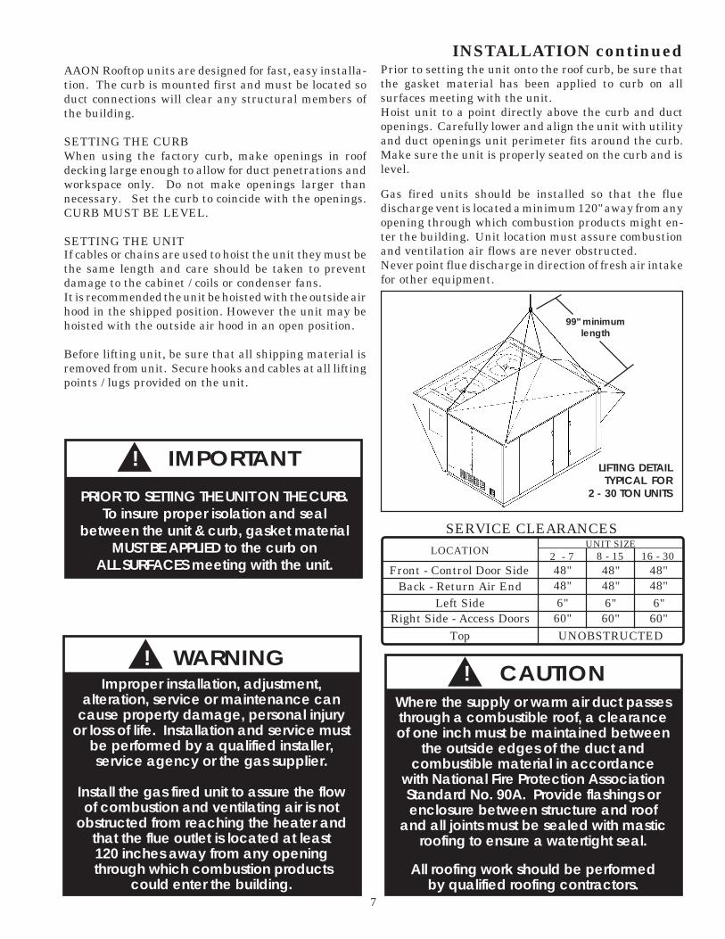
Prior to setting the unit onto the roof curb, be sure thatthe gasket material has been applied to curb on allsurfaces meeting with the unit.Hoist unit to a point directly above the curb and ductopenings. Carefully lower and align the unit with utilityand duct openings unit perimeter fits around the curb.Make sure the unit is properly seated on the curb and islevel.
Gas fired units should be installed so that the fluedischarge vent is located a minimum 120" away from anyopening through which combustion products might en-ter the building. Unit location must assure combustionand ventilation air flows are never obstructed.Never point flue discharge in direction of fresh air intakefor other equipment.
Improper installation, adjustment,alteration, service or maintenance can
cause property damage, personal injuryor loss of life. Installation and service must
be performed by a qualified installer,service agency or the gas supplier.
Install the gas fired unit to assure the flowof combustion and ventilating air is not
obstructed from reaching the heater andthat the flue outlet is located at least120 inches away from any opening
through which combustion productscould enter the building.
▲! WARNING
▲! IMPORTANT
PRIOR TO SETTING THE UNIT ON THE CURB.To insure proper isolation and seal
between the unit & curb, gasket materialMUST BE APPLIED to the curb on
ALL SURFACES meeting with the unit.
Where the supply or warm air duct passesthrough a combustible roof, a clearanceof one inch must be maintained between
the outside edges of the duct andcombustible material in accordance
with National Fire Protection AssociationStandard No. 90A. Provide flashings orenclosure between structure and roof
and all joints must be sealed with masticroofing to ensure a watertight seal.
All roofing work should be performedby qualified roofing contractors.
▲! CAUTION
Back - Return Air End
LOCATIONUNIT SIZE
2 - 7
SERVICE CLEARANCES
48"Front - Control Door Side 48"
Left Side 6"Right Side - Access Doors 60"
Top UNOBSTRUCTED
8 - 15 16 - 30
48"48"
6"60"
48"48"
6"60"
LIFTING DETAIL TYPICAL FOR
2 - 30 TON UNITS
99" minimumlength
8
ELECTRICALVerify the unit data plate voltage agrees with the powersupply. Route power and control wiring through theutility entry. Do not run power and signal wires in thesame conduit. Connect power according to the (unitspecific) wiring diagram provided.
Protect the branch circuit in accordance with code re-quirements. Control wires should not be run inside thesame conduit. The unit must be electrically grounded inaccordance with the current National Electric Code,ANSI / NFPA No. 70. In Canada use current C.S.A.Standard C22.1 Canadian Electric Code Part 1.Power wiring is to the unit terminal block or maindisconnect. All wiring beyond this point has been doneby the manufacturer and cannot not be modified withouteffecting the unit's agency / safety certification.
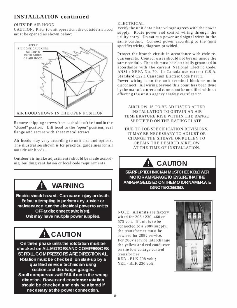
INSTALLATION continuedOUTSIDE AIR HOODCAUTION: Prior to unit operation, the outside air hoodmust be opened as shown below:
AIRFLOW IS TO BE ADJUSTED AFTERINSTALLATION TO OBTAIN AN AIR
TEMPERATURE RISE WITHIN THE RANGESPECIFIED ON THE RATING PLATE.
DUE TO JOB SPECIFICATION REVISIONS,IT MAY BE NECESSARY TO ADJUST ORCHANGE THE SHEAVE OR PULLEY TO
OBTAIN THE DESIRED AIRFLOWAT THE TIME OF INSTALLATION.
Remove shipping screws from each side of the hood in the"closed" postion. Lift hood to the "open" position, sealflange and secure with sheet metal screws.
Air hoods may vary according to unit size and options.The illustration shown is for practical guidelines for alloutside air hoods.
Outdoor air intake adjustments should be made accord-ing building ventilation or local code requirements.
NOTE: All units are factorywired for 208 / 230, 460 or575 volt. If unit is to beconnected to a 208v supply,the transformer must berewired for 208v service.For 208v service interchangethe yellow and red conductoron the low voltage controltransformer.RED - BLK 208 volt ;YEL - BLK 230 volt.
▲! CAUTIONSTART-UP TECHNICIAN MUST CHECK BLOWER
MOTOR AMPERAGE TO ENSURE THAT THEAMPERAGE LISTED ON THE MOTOR NAMEPLATE
IS NOT EXCEEDED.
▲On three phase units the rototation must be
checked on ALL MOTORS AND COMPRESSORS.SCROLL COMPRESSORS ARE DIRECTIONAL.Rotation must be checked on start-up by a
qualified service technician usingsuction and discharge gauges.
Scroll compressors will FAIL if run in the wrongdirection. Blower and condenser rotationshould be checked and only be altered if
necessary at the power connection.
! CAUTION
▲! WARNINGElectric shock hazard. Can cause injury or death.
Before attempting to perform any service ormaintenance, turn the electrical power to unit to
OFF at disconnect switch(es).Unit may have multiple power supplies.
APPLYSILICONE CAULKING
ON TOP &BOTH SIDES
OF AIR HOOD
AIR HOOD SHOWN IN THE OPEN POSITION
9
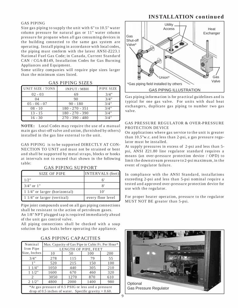
GAS PIPINGSize gas piping to supply the unit with 6" to 10.5" watercolumn pressure for natural gas or 11" water columnpressure for propane when all gas consuming devices inthe building connected to the same gas system areoperating. Install piping in accordance with local codes,the piping must conform with the latest ANSI-Z223.1National Fuel Gas Code; in Canada, Current StandardCAN / CGA-B149, Installation Codes for Gas BurningAppliances and Equipment.Some utility companies will require pipe sizes largerthan the minimum sizes listed.
NOTE: Local Codes may require the use of a manualmain gas shut-off valve and union, (furnished by others)installed in the gas line external to the unit.
GAS PIPING is to be supported DIRECTLY AT CON-NECTION TO UNIT and must not be strained or bentand shall be supported by metal straps, blocks or hooksat intervals not to exceed that shown in the followingtable:
Pipe joint compounds used on all gas piping connectionsshall be resistant to the action of petroleum gases.An 1/8" NPT plugged tap is required immediately aheadof the unit gas control valve.All piping connections shall be checked with a soapsolution for gas leaks before operating the appliance.
INSTALLATION continued
SIZE OF PIPE INTERVALS (feet)GAS PIPING SUPPORT
1/2" 6'3/4" or 1" 8'1 1/4" or larger (horizontal) 10'1 1/4" or larger (vertical) every floor level
NominalIron Pipe
Size, Inches 10 50 100 200
GAS PIPING CAPACITIES
3/4" 278 115 79 55 1" 520 215 150 100 1 1/4" 1050 440 305 210 1 1/2" 1600 670 460 320 2 3050 1270 870 610 2 1/2" 4800 2000 1400 980
LENGTH OF PIPE, FEETMax. Capacity of Gas Pipe in Cubic Ft. Per Hour*
*At gas pressure of 0.5 PSIG or less and a pressuredrop of 0.5 inches of water. Specific gravity = 0.60.
UNIT SIZE / TONS INPUT / MBH
GAS PIPING SIZES
02 - 03 69 3/4" 04 90 3/4" 05 - 06 - 07 90 - 180 3/4" 08 - 10 180 - 270 - 351 3/4" 13 - 15 180 - 270 - 390 3/4" 16 - 30 270 - 390 - 480 3/4"
PIPE SIZE
Gas piping information is for practical guidelines and istypical for one gas valve. For units with dual heatexchangers, duplicate gas piping to number two gasvalve.
GAS PRESSURE REGULATOR & OVER-PRESSUREPROTECTION DEVICEOn applications where gas service to the unit is greaterthan 10.5"w.c. and less than 2-psi, a gas pressure regu-lator must be installed.At supply pressures in excess of 2-psi and less than 5-psi, ANSI Z21.80 line regulator standard requires ameans (an over-pressure protection device / OPD) tolimit the downstream pressure to 2-psi maximum, in theevent of regulator failure.
In compliance with the ANSI Standard, installationsexceeding 2-psi and less than 5-psi nominal require atested and approved over-pressure protection device foruse with the regulator.
For proper heater operation, pressure to the regulatorMUST NOT BE greater than 5-psi.
UtilityAccess
GasShut-offValve*
HeatExchanger
GasValve
Union*
GAS PIPING ILLUSTRATION
*Gas piping field installed by others
OptionalGas Pressure Regulator

10
INSTALLATION continued
CONDENSATE PIPINGAAON units are equipped with drain connections and 'P'traps are furnished with the equipment. All drainconnections must be used and individually trapped toensure a minimum amount of condensate accumulationin the drain pans.
Drainage of condensate directly onto the roof may beacceptable in certain areas, refer to applicable codes. Ifcondensate is to drain directly onto the roof, a small drippad should be placed below the drain to protect the rooffrom possible damage.
When condensate is piped into the building drainagesystem, the drain pipe must penetrate the roof externalto the unit itself. The drain line should be pitched awayfrom the unit at least 1/8" per foot. On longer runs, anair break should be used to ensure proper drainage.
Drain pans in air conditioning equipment have moisturepresent and require periodic cleaning to remove build upof algae and/or bacteria. Cleaning of the drain pansreduce probability of plugged drain lines and overflow ofthe pan itself. All cleaning of the drain pans and insideof the equipment should be done by qualified personnel.
The furnace must be isolated by closing the manual shutoff valve or disconnected from the gas supply pipingduring pressure testing of the piping system with pres-sures in excess of 1/2 PSIG.
The flow of combustion and ventilating air shall not beblocked or otherwise obstructed in any way.
After electrical power is turned on, set unit controls forheating, and check for operation.
When checking burner operation, flames should be ob-served as blue with slight or no yellow tipping. Thereshould be no sign of flames floating or lifting off or awayfrom the main burners.
NOTE: In case emergency shut down is required, turnoff the main manual gas shut-off valve and disconnectmain electrical power to unit. These devices should beproperly labeled by the installer.
IMPORTANT NOTICE:All gas-fired heat exchangers are completely tested atthe factory before shipment. This will remove nearly allof the oils that have been used in the manufacturingprocess, however, trace amounts may remain. Whenperforming the initial start-up at the jobsite, it is highlyrecommended that people or any other living animals,that may be sensitive to the residual odors or gases, NOTbe present in the conditioned space during the start-up.In all cases, including the initial factory firing andtesting, all of the gases will be under the minimumacceptable level of concentration for human occupancy.
DO NOT USE OPEN FLAME OR OTHER SOURCEOF IGNITION FOR LEAK TESTING.
When pressure testing the gas supply piping, thefurnace must be isolated or disconnected by
closing the individual manual shut-off valve fromthe gas supply. Gas valves can be damaged if
subjected to more than 0.5 psig pressure.
! WARNING
Some soaps used for leak detection arecorrosive to certain metals. Carefully
rinse piping thoroughly after leaktest has been completed.
! CAUTION
Those sensitive to odors or gases fromtrace amounts of residual oilsshould NOT be present in the
conditioned space during the start-upof a gas-fired installation.
! WARNING
Typical 'P' trapconnection
FOR PROPER UNIT OPERATION,DRAIN TRAP MUST BE INSTALLED AS SHOWN.
USE ABS TYPE CEMENT TO JOIN THE CONNECTIONS.

11
GAS UNIT LIGHTING INSTRUCTIONS
WARNING: IF YOU DO NOT FOLLOW THESE INSTRUCTIONS EXACTLY, A FIRE OR EXPLOSION MAY RESULT CAUSING PROPERTY DAMAGE, PERSONAL INJURY OR LOSS OF LIFE.
A. This appliance does not have a pilot. It is equipped with anignition device which automatically lights the burner.Do not try to light the pilot by hand.
B. BEFORE OPERATING smell all around the appliance areafor gas. Be sure to smell next to the floor because some gasis heavier than air and will settle on the floor.
WHAT TO DO IF YOU SMELL GAS• Do not try to light any appliance.• Do not touch any electric switch; do not use any phone
in your building.• Immediately call your gas supplier from a neighbor's phone.
Follow the gas supplier's instructions.
• If you cannot reach your gas supplier, call the fire department.
C. Use only your hand to push in or turn the gas control knob.Never use tools. If the knob will not push in or turn by hand,don't try to repair it, call a qualified service technician. Forceor attempted repair may result in a fire or explosion.
D. Do not use this appliance if any part has been under water.Immediately call a qualified service technician to inspect theappliance and to replace any part of the control system andany gas control which has been under water.
OPERATING INSTRUCTIONS5. Open control access panel.
6. Push in gas control knob slightly and turn clockwise to "OFF".NOTE: Knob cannot be turned to "OFF" unless knob is pushedin slightly. Do not force.
7. WAIT five (5) minutes to clear out any gas. Then smell for gas, includingnear the floor. If you smell gas, STOP! Follow "B" in the safetyinformation above on this label. If you don't smell gas, go to the next step.
8. Turn gas control knob counterclockwise to "ON".
9. Close control access panel.
10. Turn on all electric power to the appliance.
11. Set thermostat to desired setting.
12. If the appliance will not operate, follow the instructions"To Turn Off Gas To Appliance" and call your servicetechnician or gas supplier.
1. STOP! Read the safety information above this label.
2. Set the thermostat to lowest setting.
3. Turn off all electric power to the appliance.
4. This appliance is equipped with an ignition device whichautomatically lights the burner. Do not try to light the pilot byhand.
1. Set the thermostat to lowest setting.
2. Turn off all electric power to the appliance if serviceis to be performed.
3. Open control access panel.
4. Push in gas control knob slightly and turn clockwise to"OFF". Do not force.
5. Close control access panel.
ON
OFFGAS INLET
TO TURN OFF GAS TO APPLIANCE
GAS CONTROL KNOBSHOWN IN "ON"POSITION
FOR YOUR SAFETY READ BEFORE OPERATING

12
PERIODIC INSPECTION PROCEDURES
GAS HEATING UNITS1. The flow of combustion and ventilating cannotbe obstructed in any way. The indoor blower, evaporatorcoil and filters must be inspected monthly.
2. Once each year, prior to the heating season, aqualified technician must inspect all flue product carry-ing areas of the furnace and main burners for continuedsafe operation.
WARNING: At least once each year, a qualified ser-vice technician should check out all of the items listedunder the servicing and trouble shooting and mainte-nance section of this manual.
3. If the induced draft blower/motor assembly re-quires replacement, an airtight seal between the blowerhousing and the burner box must be restored. Hightemperature silicone sealant must be used to ensure agood seal.
4. GAS BURNERSTHE BURNERS SHOULD NEVER REQUIRECLEANING.If cleaning is necessary, it indicates faulty operation ofthe unit. The cleaning should be done only by a qualifiedservice agency after consultation with an AAON ServiceRepresentative.If the gas burners require cleaning, call an AAON ServiceEngineer at (918) 583-2266.
5. HEAT EXCHANGERThe necessity for cleaning the exchanger could indicatefaulty operation and should be checked only by a quali-fied service agency after they have discussed the prob-lem with a Service Representative.
Heat Exchanger prior to installation in unit.
Combustion Motor Flue Outlet
Burner Assembly
Manifold
BurnerHorn (typ)
Flame Sensor
Spark Rod

13
PERIODIC INSPECTION PROCEDURES Continued
COOLING1. Main Power Switches are on and power is to the unit.
2. Set thermostat in cooling mode and place the "fan"switch to on. Check blower for correct operatingdirection, amperage and voltage.
3. PACKAGED UNITS - Check compressor operation.Check the amperage and compare to the nameplatedata (check amperage load side of the compressorcontactor).
4. DX COIL UNITS / AIR HANDLERS - If a remotecondenser is applicable, inspections and service mustfollowed according to the manufacturer's instruc-tions and recommendations.
5. CHILLED WATER UNITS - Check remote chilleroperations according to the manufacturers instruc-tions. Check coolant flow valves for correct operationand settings.
HEATING • NATURAL GAS1. Before turning on the main electrical power switch,
be sure that all gas supply lines have been purged ofair.
2. Turn gas valve to "ON" position.
3. Turn main electrical power switch to "ON" and setthe thermostat to call for heat. The vent motorshould operate. The control will automaticallysupply energy to the spark gap and the gas valveafter the thermostat contact closes.
4. The sensing probe detects the presence of the flame.(Should no flame be detected in 10 seconds, theignition system will recycle. If no flame is detectedin 3 tries, the ignition system will lockout).
5. Adjust thermostat to a low temperature setting toopen contacts. The main gas flames should beextinguished.
NOTE: The evaporator blower is controlled by theignition system. In the fan "Auto" mode the blowercomes on 45 seconds after flame is proved and goes off120 seconds after the thermostat opens.
HEATING • ELECTRIC1. Set thermostat in the heat mode.
2. Set thermostat to call for heat to engage all electricheat strips. Check blower for proper rotation andvoltage.
3. Measure the amperage and voltage. Compare themto the nameplate data.
HEATING • STEAM OR HOT WATER1. Set thermostat in the heat mode.
2. Check supply blower for proper rotation and voltage.
3. Check boiler or hot water operations according to themanufacturer's instructions and recommendations.
4. Check control flow valves for correct operation andsettings according to the manufacturer's instruc-tions and recommendations.
ELECTRIC, STEAM, HOT WATER, COOLING &CHILLED WATER UNITS
1. Blower, coils and filters should be inspected monthly.
2. Once a year, before unit is turned on for the heatingseason, a qualified service technician should inspectthe unit for proper operation.
3. All valves and steam traps should be inspectedaccording to the manufacturer's instructions andrecommendations.
WARNING: All of the items listed under the service,trouble shooting and maintenance section of this manualshould be performed once a year.
▲! CAUTION
Before leaving installation, a completeoperating cycle should be observed
to verify that all componentsare functioning properly.

14
SERVICING, TROUBLE SHOOTING & MAINTENANCE
LUBRICATIONAll original blower motors and bearings are furnishedwith an orginal factory charge of lubrication. Someapplications will require that bearings be re-lubricatedperiodically. The schedule will depend on the operatingduty, temperature variations or other harsh atmosphericconditions.
Bearings should be re-lubricated when at normal oper-ating temperatures, but not during operation. Rotatethe fan shaft manually and add minimum lubricantrequired to purge the seals. DO NOT OVERLUBRICATE.
Recommended lubricants are:SHELL OIL - DOLIUM RCHEVRON OIL - SRI No. 2TEXACO INC. - PREMIUM RB
SERVICEIf the unit does not function properly and service isrequired, service technicians qualified and experiencedin both gas, electric heating and air conditioning arepermitted to provide service to keep warranties in effect.The service technician should call the factory if assis-tance is required.
SERVICE TECHNICIAN MUST PROVIDE THEMODEL AND SERIAL NUMBER OF THE SPECIFICUNIT TO CUSTOMER SERVICE TO ASSURE A COR-RECT DIAGNOSIS.
AAON, Inc.Phone: 918-583-2266Fax: 918-382-6364
Customer Service Department
COMMON CAUSES OF REDUCED AIR FLOW
A. DIRTY FILTERS - Filters must be inspected andreplaced on a regular basis. It is strongly recommendedthat the media be replaced monthly. Clean filters areyour best protection against premature system break-down.
Do not operate the unit without the filters in place.Operation of the unit without filters will result in aclogged evaporator coil - a very expensive service prob-lem to resolve.
B. OBSTRUCTION TO AIR FLOW - Supply andreturn air grilles must be kept clear so air can be freelydischarged from and drawn into the system.
CLEANINGInspect unit interior at the beginning of each heatingand cooling season and as operating conditions require.
COILSEvaporator coil(s) should be inspected and cleaned an-nually to ensure there is no obstruction to air flow.
Condenser coil(s) should be inspected monthly. Cleancondenser coils annually or as required by location andoutdoor air conditions.
CONDENSATE DRAINCheck and clean annually at start of cooling season.
BLOWERInspect blower and blower section to keep free of dust ordebris.
TURN OFF POWER BEFORE ATTEMPTING TOCLEAN BLOWER WHEEL.
▲! WARNINGELECTRIC SHOCK HAZARD.
Shut off all electrical power to unit to avoidshock hazard or injury from rotating parts.
Typical slide-out blower section

15
Before inspecting or replacing the filters, be sure theunit IS NOT operating. The filters are located in thefilter access section of the unit. Open filter access door,and pull filters straight out to inspect. Inspect ALLfilters each time. Replace filters with the size indicatedon each filter or as shown in the filter chart below. Arrowon replacement filters must point towards the blower.Monthly inspection is required to maintain optimumefficiency.
NOTE: CHART REFLECTS STANDARD FACTORY SUPPLIED FILTERS AND SIZES.CONTACT FACTORY FOR SPECIAL OPTIONAL FILTER PACKAGES.
FILTERS
FILTERS SHOULD BE REPLACED EVERY 30 DAYS OR AS REQUIRED.
FILTER SIZEUNIT SIZE
16" x 20"Standard 2" Throwaway 4 6
4
2 - 5 6 & 7 8 & 10 13 & 15 16 - 30
16" x 20"Optional 2" or 4" Pleated
20" x 25"Optional 2" or 4" Pleated
6
6
4 6
IT IS IMPORTANT TO KEEP COILS, BLOWER AND FILTERS CLEAN !
FILTER INSTALLATION / REPLACEMENT
▲! WARNINGBefore attempting to perform any serviceor maintenance, turn the electrical power
to unit to OFF at disconnect switch(es).Unit may have multiple power supplies.
Slide-outfilters
OptionalEconomizer
Optional R/Asmoke detectorlocation
16
BURNER GOES "OFF" ON HIGH LIMIT
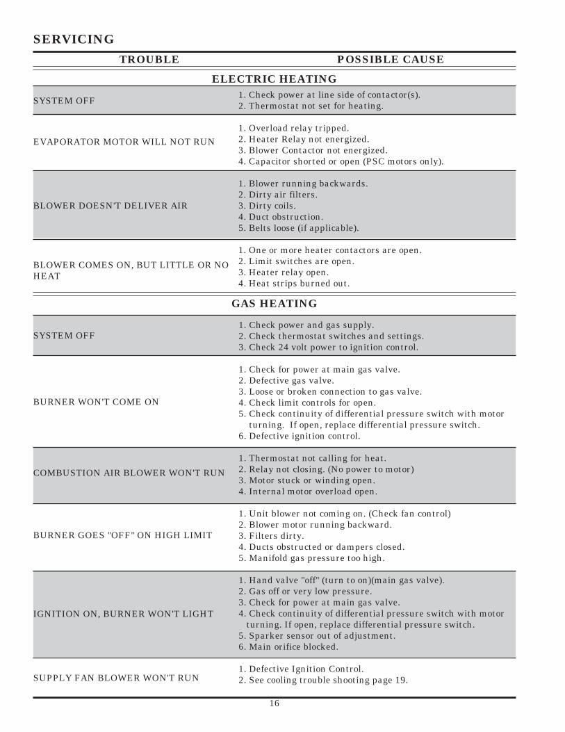
SERVICINGTROUBLE POSSIBLE CAUSE
ELECTRIC HEATING
SYSTEM OFF1. Check power at line side of contactor(s).2. Thermostat not set for heating.
1. Overload relay tripped.2. Heater Relay not energized.3. Blower Contactor not energized.4. Capacitor shorted or open (PSC motors only).
1. Blower running backwards.2. Dirty air filters.3. Dirty coils.4. Duct obstruction.5. Belts loose (if applicable).
1. One or more heater contactors are open.2. Limit switches are open.3. Heater relay open.4. Heat strips burned out.
BLOWER DOESN'T DELIVER AIR
EVAPORATOR MOTOR WILL NOT RUN
1. Check power and gas supply.2. Check thermostat switches and settings.3. Check 24 volt power to ignition control.
1. Check for power at main gas valve.2. Defective gas valve.3. Loose or broken connection to gas valve.4. Check limit controls for open.5. Check continuity of differential pressure switch with motor turning. If open, replace differential pressure switch.6. Defective ignition control.
1. Thermostat not calling for heat.2. Relay not closing. (No power to motor)3. Motor stuck or winding open.4. Internal motor overload open.
1. Unit blower not coming on. (Check fan control)2. Blower motor running backward.3. Filters dirty.4. Ducts obstructed or dampers closed.5. Manifold gas pressure too high.
1. Hand valve "off" (turn to on)(main gas valve).2. Gas off or very low pressure.3. Check for power at main gas valve.4. Check continuity of differential pressure switch with motor turning. If open, replace differential pressure switch.5. Sparker sensor out of adjustment.6. Main orifice blocked.
1. Defective Ignition Control.2. See cooling trouble shooting page 19.
SYSTEM OFF
BLOWER COMES ON, BUT LITTLE OR NOHEAT
IGNITION ON, BURNER WON'T LIGHT
GAS HEATING
COMBUSTION AIR BLOWER WON'T RUN
BURNER WON'T COME ON
SUPPLY FAN BLOWER WON'T RUN
17
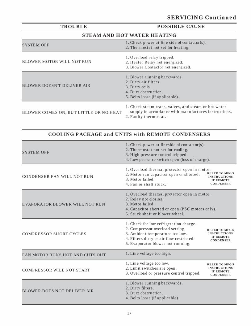
TROUBLE POSSIBLE CAUSE
STEAM AND HOT WATER HEATING1. Check power at line side of contactor(s).2. Thermostat not set for heating.
1. Overload relay tripped.2. Heater Relay not energized.3. Blower Contactor not energized.
1. Blower running backwards.2. Dirty air filters.3. Dirty coils.4. Duct obstruction.5. Belts loose (if applicable).
1. Check steam traps, valves, and steam or hot water supply in accordance with manufactures instructions.2. Faulty thermostat.
SYSTEM OFF
SERVICING Continued
BLOWER MOTOR WILL NOT RUN
BLOWER DOESN'T DELIVER AIR
BLOWER COMES ON, BUT LITTLE OR NO HEAT
FAN MOTOR RUNS HOT AND CUTS OUT
1. Check power at lineside of contactor(s).2. Thermostat not set for cooling.3. High pressure control tripped.4. Low pressure switch open (loss of charge).
1. Overload thermal protector open in motor.2. Motor run capacitor open or shorted.3. Motor failed.4. Fan or shaft stuck.
1. Overload thermal protector open in motor.2. Relay not closing.3. Motor failed.4. Capacitor shorted or open (PSC motors only).5. Stuck shaft or blower wheel.
1. Check for low refrigeration charge.2. Compressor overload setting.3. Ambient temperature too low.4. Filters dirty or air flow restricted.5. Evaporator blower not running.
1. Line voltage too high.
1. Line voltage too low.2. Limit switches are open.3. Overload or pressure control tripped.
1. Blower running backwards.2. Dirty filters.3. Duct obstruction.4. Belts loose (if applicable).
SYSTEM OFF
REFER TO MFG'SINSTRUCTIONS
IF REMOTECONDENSER
BLOWER DOES NOT DELIVER AIR
COMPRESSOR WILL NOT START
COMPRESSOR SHORT CYCLES
EVAPORATOR BLOWER WILL NOT RUN
CONDENSER FAN WILL NOT RUN
REFER TO MFG'SINSTRUCTIONS
IF REMOTECONDENSER
REFER TO MFG'SINSTRUCTIONS
IF REMOTECONDENSER
COOLING PACKAGE and UNITS with REMOTE CONDENSERS

18
TROUBLE POSSIBLE CAUSE
1. Check power at line side of contactor(s).2. Thermostat not set for cooling.
1. Overload thermal protector open in motor.2. Contactor not closing.3. Motor failed.
1. Line voltage too high.
1. Blower running backwards.2. Dirty air filters.3. Duct obstruction.4. Belt loose (if applicable).
1. Check supply water and temperature.2. Check water control valves operation.3. Check water temperature rise entering and leaving unit to determine if adequate water is flowing.
SYSTEM OFF
SERVICING Continued
COOLING - CHILLED WATER
EVAPORATOR BLOWER WILL NOT RUN
ROOFTOP UNIT REPLACEMENT PARTSReplacement parts for AAON equipment may be obtained from AAON. When ordering parts, always reference theunit model number, serial number and part number.
AAON, Inc.Customer Service Department
2425 South Yukon Ave • Tulsa, Oklahoma 74107Phone: 918-583-2266 • Fax: 918-382-6364
ALWAYS USE AAON SPECIFIED PARTS
FAN MOTOR RUNS HOT AND CUTS OUT
BLOWER DOES NOT DELIVER AIR
BLOWER COMES ON, BUT LITTLE OR NOCOOLING

19
SEQUENCE OF OPERATIONS
I. GENERAL INFORMATION
A. HEATING
1. Natural GasWhen the thermostat calls for heating, W1 makes R tothe heat relay (HR). All N.O. (Normally open) contactsclose and all N.C. (normally closed) contacts open. Thecombustion motor starts and as the pressure decreases inthe flue outlet box the ignition control is energized. Thecontrol sends 24 VAC to the main gas valve and highvoltage to the ignitor. If a burner flame has been detectedafter 10 seconds, the spark is extinguished and the flamecontinues. If a flame has not been detected after 10seconds, the gas valve closes, the spark ceases and theinduced draft blower continues to purge the heat ex-changer. After 45 seconds of purge, the ignition systemwill attempt to light the burners again. Should no flamebe detected after 3 attempts, the ignition control locks outthe system.
On a fault the gas train is shut down by a main limitswitch located in the heat exchanger area or by anauxiliary limit mounted in the supply air fan housing.
2. LP (Propane) GasThe sequence for LP Gas is the same as above but uponnon-proof of burner the gas train will enter a 100%lockout condition.
3. ElectricWhen the thermostat calls for heat 'W1' makes 'R' to theheat relay 'HR'. All N.O. contacts close, and all N.C.contacts open. The heat relay makes 'R' to the first stageof electric heat.
On a fault condition the main limit located in the supplyair or the auxiliary limit located in the supply air fanhousing will remove power from all contactors.
If additional heating is required a second set of elementscan be turned on by 'W2'.OPTIONAL - When available the electric heat can besequenced to provide a constant discharge air tempera-ture.
4. Steam or Hot WaterThis option adds a steam coil down stream of the coolingcoil (if supplied). Connections and controls are providedby others.
B. COOLING
1. Packaged UnitsWhen the thermostat calls for cooling from the space, 'Y1'makes 'R' to 'CC1' through the LPS (low pressure switch),HPS (high pressure switch) and optional GOT (guaran-tee off timer).
2. DX Only - Coil UnitsWhen the thermostat calls for cooling from the space, thecondensing unit is energized (refer to manufacturersinstructions for sequence of operation). The evaporatorblower contactor is energized simultaneously with thecondensing section.
3. Chilled Water Coil UnitsThe blower contactor is energized to provide supply air ona signal from the space thermostat. All other controls areby others.
C. OPTIONAL ECONOMIZERWhen cooling is called for and the unit has the econo-mizer option installed, temperature switch ECS (or En-thalpy) allows the economizer operation when the out-side air reaches the required setpoint. (Some options usedry bulb sensing and some options use enthalpy sensingto determine the outside air (O.A.) condition).When the economizer is in operation 'Y1' controls theopening and closing of the dampers, 'Y2' is then able tocontrol the compressors which 'Y1' normally controls. Amodulating economizer is also available. The operationis the same as the standard economizer except that themotor modulates the damper position to maintain apreset mixed air temperature.

20
II. VAV (Variable Air Volume) SYSTEMS
NOTE: VAV BOXES AND CONTROLS ARESUPPLIED BY OTHERS FOR FIELD INSTALLATION.
When a call for cooling is received, the controller boardstages on compressors to maintain a field set supply airtemperature. As different zones become satisfied theirVAV boxes will close. This in turn causes the supply ductpressure to rise. The VAV controller board senses thisincrease in pressure and modulates the supply fan speedto maintain the required field set supply air pressuresetpoint.
Normally VAV units are cooling only units. There arecertain applications where electric or gas heat is used toprovide morning warmup. When gas or electric heat isused for morning warmup the airflow will not be allowedto vary. The fan speed control will be disabled until a callfor cooling is received, then the heating system will belocked out and VAV will be enabled.
III. POWER EXHAUST OPTIONS
When space over pressurization occurs, due to econo-mizer operation, a power exhaust will be utilized toprovide relief.
A. When three position economizer is called for, anOn/Off power exhaust will be used.
POWER EXHAUST w/ 3 POSITION ECON.
In the unit "OFF" or in the minimum economizerposition, the power exhaust fan is off. When the unitgoes to 100% outside air operation, the powerexhaust fan motor starts and operates until the unitis shut off or the economizer goes back to minimumposition.
The end switch located on the economizer outside airdamper section, is field adjustable to allow for differencesin building design. The switch engages and disengagesthe power exhaust motor(s) through a contactor. The endswitch is included in the 24 VAC circuit.
B. Full modulating economizer, a full modulating powerexhaust will control the amount of actual exhaustedair by means of a building sensing pressure controlwhich opens or closes according to desired pressurein the space.
POWER EXHAUST w/ FULL MODULATING ECON.In the unit "OFF" or in the minimum economizerposition, the power exhaust is off. As the economizerbegins to modulate open, an end switch (adjustable)closes which starts the power exhaust fan motor.The power exhaust operates until the economizermodulates below the end switch setting or the unit isshut off.
POWER EXHAUST w/ FULL MODULATING ECON.WITH BUILDING PRESSURE CONTROL
In the unit "OFF" or in the minimum economizer positionthe power exhaust is off. As the economizer begins tomodulate open, an end switch (adjustable) closes whichstarts the power exhaust fan motor. The amount ofexhaust air is controlled by a set of dampers in responseto the unit mounted building static pressure controller.The power exhaust operates until the economizer modu-lates below the end switch setting or the unit is shut off.
(NOTE: Static pressure sensing tubing is field suppliedand installed).
SEQUENCE OF OPERATIONS Continued
21
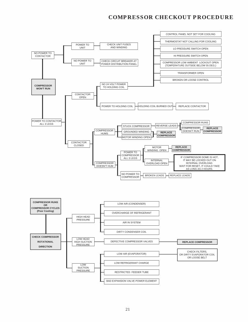
STUCK COMPRESSOR
MOTOR WINDING OPEN
COMPRESSOR RUNSREVERSE LEADS
CHECK UNIT FUSESAND WINDING
GROUNDED WINDING
INTERNALOVERLOAD OPEN
REPLACECOMPRESSOR
COMPRESSOR CHECKOUT PROCEDURE
NO POWER TOCONTACTOR
POWER TOUNIT
NO POWER TOUNIT
COMPRESSORWON'T RUN
CHECK CIRCUIT BREAKER ATPOWER DISTRIBUTION PANEL
NO 24 VOLT POWERTO HOLDING COIL
CONTACTOROPEN
POWER TO HOLDING COIL HOLDING COIL BURNED OUT REPLACE CONTACTOR
BROKEN OR LOOSE CONTROL
TRANSFORMER OPEN
COMPRESSOR LOW AMBIENT LOCKOUT OPEN(TEMPERATURE OUTSIDE BELOW 55 DEG.)
HI PRESSURE SWITCH OPEN
LO PRESSURE SWITCH OPEN
THERMOSTAT NOT CALLING FOR COOLING
CONTROL PANEL NOT SET FOR COOLING
COMPRESSORDOESN'T RUN
REPLACECOMPRESSOR
REPLACECOMPRESSOR
MOTORWINDING OPEN
POWER TOCOMPRESSOR
ALL 3 LEGS
COMPRESSORDOESN'T HUM
IF COMPRESSOR DOME IS HOT,IT MAY BE LOCKED OUT ON
INTERNAL OVERLOAD.WAIT FOR RESET, IT COULD TAKE
AS LONG AS 2 HOURS.
REPLACE LEADSBROKEN LEADSNO POWER TOCOMPRESSOR
COMPRESSORHUMS
CONTACTORCLOSED
POWER TO CONTACTORALL 3 LEGS
LOW AIR (CONDENSER)
OVERCHARGE OF REFRIGERANT
AIR IN SYSTEM
DIRTY CONDENSER COIL
HIGH HEADPRESSURE
LOW HEADHIGH SUCTION
PRESSUREDEFECTIVE COMPRESSOR VALVES
LOW AIR (EVAPORATOR)
LOW REFRIGERANT CHARGELOW
SUCTIONPRESSURE
RESTRICTED FEEDER TUBE
BAD EXPANSION VALVE POWER ELEMENT
REPLACE COMPRESSOR
CHECK FILTERS,OR DIRTY EVAPORATOR COIL
OR LOOSE BELT
COMPRESSOR RUNSOR
COMPRESSOR CYCLES(Poor Cooling)
CHECK COMPRESSOR
ROTATIONAL
DIRECTION

22
IGNITION CONTROL CHECKOUT PROCEDURE
NO
IS 24v AVAILABLEAT
IGNITION CONTROL ?
NO
CORRECTION NECESSARY
IS 24v AVAILABLE ATGAS VALVE ?
YES
YES
IS FLAME SENSORCABLE SECURELY
ATTACHED ?
NO
NO
YESIS SENSOR
CERAMIC CRACKEDOR BROKEN ?
NOIS SENSOR
LOCATED INBURNER FLAME ?
YES
REPLACESENSOR
ASSEMBLY
NO
YESCHECK SENSOR
CABLECONTINUITY
NOTO.K.
REPLACE CABLE
O.K.
REPLACEIGNITIONCONTROL
CHECK GAS VALVEWIRING FOR PROPER,TIGHT CONNECTIONS
YES
IS GAS PRESSUREPER MANUFACTURE'S
SPECIFICATIONS ?
YESIS SPARK GAP
LOCATED IN GASSTREAM ?
NO
SPARK IS PRESENTBUT BURNER
WILL NOT LIGHT
NOCHECK GAS SUPPLYFOR OBSTRUCTIONSOR CLOSED VALVES
REPLACEGAS VALVE
NO
IS IGNITION CONTROLLOCKED OUT ?
CHECK TRANSFORMERAND / OR THERMOSTAT
FOR MALFUNCTIONREPLACE AS NECESSARY.
REPLACE OPEN LIMIT
YES
YES
NO
RESET BY TURNINGTHE THERMOSTAT
TO "OFF"THEN BACK TO HEAT
IS SPARK GAP 0.10 ?
YES
REGAP TO 0.10
IS ELECTRODECERAMIC CRACKED
OR BROKEN ?
NO
YES
NO
REPLACE ELECTRODE
IS HIGH VOLTAGE CABLEFIRMLY ATTACHED ANDIN GOOD CONDITION ?
YES
NO
REPLACE CONTROL
REPLACE CABLEOR CORRECTCONNECTION
NO SPARKON
CALL FOR HEAT
IS THERE 24v ATIGNITION CONTROL ?
SHOULD BE CLOSED
CHECK FUSES
WARNING: ALL SAFETY PRECAUTIONS MUST BE FOLLOWED WHEN EVALUATINGTHE IGNITION CONTROL SYSTEM ON GAS HEATING UNITS.
23
AAON , Inc.JOB NAME:
ADDRESS:
CITY, STATE:
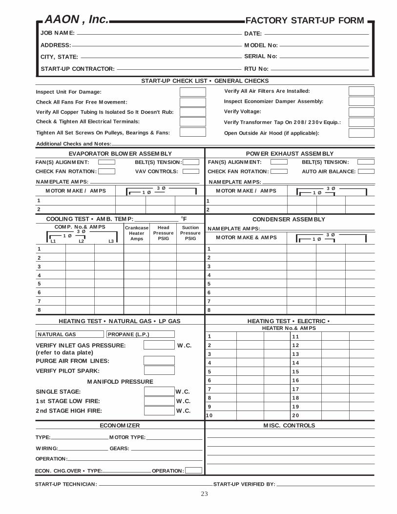
FACTORY START-UP FORM
Check & Tighten All Electrical Terminals:
Verify All Copper Tubing Is Isolated So It Doesn't Rub:
Check All Fans For Free Movement:
Inspect Unit For Damage: Verify All Air Filters Are Installed:
START-UP CONTRACTOR:
SERIAL No:
MODEL No:
DATE:
START-UP CHECK LIST • GENERAL CHECKS
RTU No:
Verify Voltage:
Verify Transformer Tap On 208/230v Equip.:
Inspect Economizer Damper Assembly:
EVAPORATOR BLOWER ASSEMBLY POWER EXHAUST ASSEMBLYFAN(S) ALIGNMENT: BELT(S) TENSION: FAN(S) ALIGNMENT: BELT(S) TENSION:
1
2
1
2
3 Ø1 ØMOTOR MAKE / AMPS 3 Ø
1 ØMOTOR MAKE / AMPS
1
2
3
4
COMP. No.& AMPS3 Ø
1 Ø
COOLING TEST • AMB. TEMP: °FHead
PressurePSIG
CrankcaseHeaterAmps
SuctionPressure
PSIG
5
6
7
8
MOTOR MAKE & AMPS
1
2
3
4
3 Ø1 Ø
8
5
6
7
L1 L2 L3
NAMEPLATE AMPS: NAMEPLATE AMPS:
CHECK FAN ROTATION: VAV CONTROLS: CHECK FAN ROTATION: AUTO AIR BALANCE:
Open Outside Air Hood (if applicable):Tighten All Set Screws On Pulleys, Bearings & Fans:
Additional Checks and Notes:
START-UP TECHNICIAN: START-UP VERIFIED BY:
CONDENSER ASSEMBLY
NAMEPLATE AMPS:
HEATING TEST • NATURAL GAS • LP GAS HEATING TEST • ELECTRIC •
1 11
2 12
3 13
4 14
5 15
6 16
7 17
8 18
9 19
10 20
HEATER No.& AMPS
2nd STAGE HIGH FIRE: W.C.
1st STAGE LOW FIRE: W.C.
SINGLE STAGE: W.C.
MANIFOLD PRESSURE
NATURAL GAS PROPANE (L.P.)
VERIFY INLET GAS PRESSURE: W.C.(refer to data plate)
VERIFY PILOT SPARK:
PURGE AIR FROM LINES:
MISC. CONTROLSECONOMIZER
TYPE: MOTOR TYPE:
ECON. CHG.OVER • TYPE: OPERATION:
OPERATION:
WIRING: GEARS:

24
RM SERIES
INSTALLATIONINSTRUCTION
MANUAL
AAON, Inc.2425 South Yukon
Tulsa, Oklahoma 74107ph: (918) 583-2266 • fax: (918) 583-6094
R15690 (7-03)
AAON ®