aam national campaign developmental testing (nc-dt
TRANSCRIPT

AAM National Campaign Developmental Testing (NC-DT) Virtual Dry RunJune 29, 2021
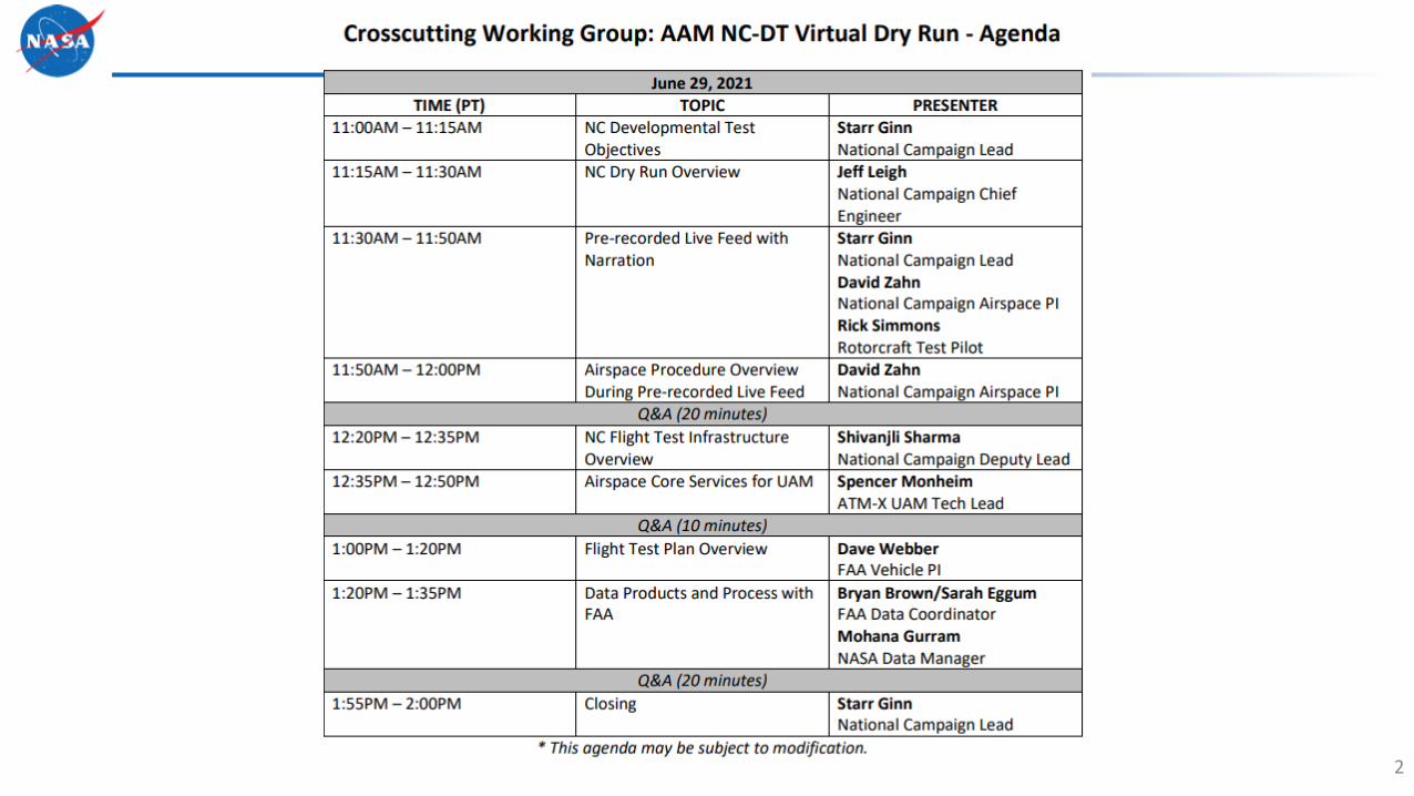
2

NC Execution in FY21 – NC Developmental Test
3
NC Partnership
Management
L1L2L3-D
NASA Testing
NC DT with Joby
Data Buys: Bell & FLE
Flights
Airspace Simulation (X3 & X4)
ACO Release
Dry Run Flight TestingFlight
Testing
CY2020 CY2021 CY2022
Q3 Q4 Q1 Q2 Q3 Q4 Q1 Q2 Q3 Q4
Scenario Development and Flight Test Objective Refinement Bell Flight
Testing
NC-1 Vehicle Information Exchange Engagements
Partner Selection
NC-1 Flight Testing
NC-1 Partner Reviews & Prep
X3 Data Collection
X4 Data Collection
FLE Flight Testing
DT Flight
Testing

NC-1 Objectives UML ½ and FAA Pillars Alignment
Accelerate Certification and Approval: Develop and assess an integrated approach to vehicle certification, pilot licensing, and operational approval.
Develop Flight Procedure Guidelines: Develop preliminary guidelines for flight procedures and related airspace design criteria.
Evaluate the Communication, Navigation, and Surveillance (CNS) Trade Space: Explore and evaluate CNS requirements, options, and trade-offs.
Demonstrate an Airspace Management Architecture: Demonstrate and document an airspace system architecture capable of safely managing scalable AAM operations without burdening the current air traffic management system.
Identify Community Integration Needs: Conduct initial characterization of the community noise of AAM vehicles through measurements of vehicle ground noise.
4
Aircraft
Infrastructure
Operations
Aircraft Airspace OperationsInfrastructure
Airspace Operations
CommunityAircraft
Aircraft
Infrastructure
Operations

NC Developmental Test Objectives
NC-DT Goal: Ensure that NASA is fully prepared to execute NC-1 event in a manner maximizing benefits to the AAM community
DTO-1: Assess Maturity and Robustness of NASA Proving GroundFull Success: Collect data to support analysis of the flight test and simulation infrastructure for Scenarios 1-4.
DTO-2: Assess Effectiveness of NC Testing Processes, Logistics, and Data CollectionFull Success: Guide one partner organization through technology readiness, test readiness, flight and simulation execution, and data collection processes.
DTO-3: Preliminary Assessment of Partner Capabilities and Systems PerformanceFull Success: Conduct flight test and simulation for at least one partner aircraft/airspace system to collect vehicle, airspace, and connectivity/communication performance data against the requirements for Scenarios 1-4.
DTO-4: Assess the Suitability of NC-1 ScenariosFull Success: Assess the applicability of the scenarios through the execution of at least three of the NC-1 scenarios with at least one vehicle and one airspace partner.
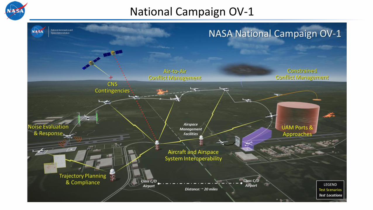
National Campaign OV-1

6 AAM NC “UAM Heliports”• 40x40ft TLOF• Northern Heliports suitable for
wind/controllability studies• All Heliport design/placement IAW
AC 150/ 5390-2C Heliport Design
1 AAM NC “UAM Vertiport”• 1090ft length x 120ft width TLOF/FATO
• + + = Research Airport
• + + = Research Airport
• = Research Airport
01H 02H 03H
AAM NC Terminal Ops01H
03H 02H
04H
05H
06H
XEDW
XVPT04H 05H
19/01
19/01
XX33
06H

4833 Helipads
8
148/328 Mag
020/200 Mag
290/110 Mag
155/335 MagNo
rth

ORION 3 Scenario 2 In-flight Re-route

Dance Card
10
Live FlightVideo Playback

JEFF LEIGHNational Campaign Chief Engineer
11

Key activities to support Dry Run and DT Flight Objectives• A series of Performance, Trim, Stability, and Control flight test maneuvers intended to
support or validate vehicle flight manual performance, operating characteristics, or operational limitations (Vehicle Characteristics) these classical, proven, test techniques provide data
that support compliance findings against current FAA minimum requirements for vertical flight aircraft dependent on the operational use case
• A set of ground and flight tasks that represent the “building blocks” that make up a UAM mission, including simulated IMC approaches to defined “UAM Heliports” and “UAM Vertiports” in controlled, but varied, conditions (UAM Task Elements) these “developmental”
test techniques are intended to support FAA civil certification compliance findings for UAM aircraft that utilize highly-augmented flight control systems and/or “simplified vehicle operations.” NASA is a key collaborative partner with FAA for development of these so-called “Mission Task Elements.”
• Flyability evaluations of research UAM approaches, departures, and enroute procedures utilizing an FAA evaluation application which operates independently from the flight vehicles’ avionics (Approach, Departure, Route Flight Checks)
• Flights that are specifically designed to simulate a “real world” urban air taxi mission including pre-flight planning, ground operations, flight operations, air traffic management and contingencies expected in the UAM mission. (Scenarios Testing). 12

Build 2 Purpose and Scope
• Purpose– Facilitate the development of the data collection systems and mobile range infrastructure
required for NC-1;
– Refine the NC Scenarios, test techniques, and safety assurance processes; and
– Capture foundational vehicle and operational data to support evolutions in vehicle, infrastructure, and airspace requirements that will enable the advent of UAM in the National Airspace System (NAS).
• Scope– Approximately 25 hours of flight activity using a helicopter within the Dry Run Flight Test
Infrastructure
– Meet Flight Test Plan (FTP) objectives
– Build on the lessons learned during December’s Fam Flights.
– Integrate and test additional infrastructure systems to include PLASI, differential GPS, and additional helipads at building 4833 and X-33

Key activities to support Dry Run and DT Flight Objectives
14

Build 2 Flight Test Infrastructure Overview
15
Redlined differences to final configuration
MCC
Flight CrewPaul Davidovich FRI Pilot(Flight Research Inc)
Jon Jordan FAA Cert PilotDave Webber FAA FTE(Flight Test Engineer)
Jay Sandwell FAA FIAPA(Flight Inspection AirborneProcessor Application)

SHIVANJLI SHARMANational Campaign Deputy Lead
16

National Campaign – Data and Information Exchange
17
National Campaign Operational Demos Data Collection & Analysis
• FAA access to shared database and collaborative analysis to inform gaps in policy and standards
• Sharing key outcomes with standards bodies
• Using data to inform NASA/FAA Working Groups including development of concept of operations
• Leveraging ULIs to ensure consistent development with research institutions
• Community engagement through AAM Ecosystem Working Groups
Data Needs and Requirements
FAA
NASA Research Projects
Industry Partners
Gap Analysis for Current Standards
MBSE Approach for CC
National Campaign Flight Test Infrastructure

Dry Run - Lessons Learned
18
Assessment of Flight Test Infrastructure• Determined maturity and performance requirements of flight test infrastructure components• Understood integration needs as well as power and connectivity requirements
Development of NC Flight Test Plan• Established flight test points comprised of flight maneuvers and vehicle characteristics expected by UAM vehicles• Providing Cooper Harper ratings on control margin with FAA Test Pilots and Flight Test Engineers• Evaluating FAA Subpart B regulatory airworthiness standards
Assessment of Integrated Operations and Scenarios• Simulated future UAM missions including pre-flight planning, ground operations, flight operations, and contingencies • Real time ADS-B inputs to inform an airspace component (provided by ATM-X UAM) to represent a future third party airspace
provider
Development of Infrastructure and UAM Approach and Departure Procedures• UAM approach and departure procedure design including iteration on angles and descent rates that incorporate vehicle
dynamics as well as passenger ride quality• Developed infrastructure requirements by establishing vertiport and heliport dimensions and markings
Assessed Data Collection Equipment and Procedures• Exercised data collection systems including a differential GPS system, instrumentation on board the vehicle, as well as
instrumentation provided by the FAA (FIAPA - Flight Inspection Airborne Processor Application)• Developed data models, database schemas, and access controls to facilitate data analysis

NC Dry Run – Functional Architecture
19
NASA PSU & Core Airspace Services
Providers of Services to UAM (PSU) Network & Data Collection
Real Time Data Visualization
LVC Traffic Airspace Adaptation/
Urban Layer
AD
S-B
NPSU Operations Planner (xTM client)
ADS-B Receiver
Mission Control Center (MCC)
Area Surveillance
Weather
Test Site Infrastructure
ATM-X UAM
Comms
Instrumentation Box
Heliports/Vertiports
EAFB Airspace

Build 2 Flight Test Component Diagram
20

AIRSPACE COMPONENTSSpencer Monheim
ATM-X UAM Sub-project Airspace Integration Testing & Demonstration Tech Lead
21

Airspace Components – UAM Subproject
• PSU – Provider of Services to
UAM:
• Communication Airspace
Component between
Operators
• Discovery – Informs a PSU of
other PSUs operating in an
airspace
• Authorization – ANSP-actor
component, verifies the
authenticity of a PSU/Operator

NPSU (NASA Provider of Services for UAM) High-Level Overview
• Communication standard was
collaboratively developed and
tested by Industry and Public
Stakeholders
• Functionality of PSU is
derived from FAA Conops
Demonstrating a working reference PSU in flight acts as catalyst for Private Sector Development

NPSU Operation Diagram Example (scenario 1)
NPSUOperator
Plan an operation
Send Planned Operation
Airspace System
Propose Operation
Accepted / Declined Propose Operation
NPSUOperator
Plan an operation
Send Planned Operation
Airspace System
Propose Operation
Accepted / Declined
Future Information Flow
Flight Demonstration provides opportunity to
test data/information flow in a future UAM
Airspace System
Pilot

Next Steps
• X3 Simulation and NC Dry Run set foundation through
executing operations in single operator baseline
• X4 Simulation increases complexity and
interconnectivity through interactions between two
simultaneous operators, one NASA operator and one
Industry operator
• X4 Simulation enables testing concepts and software
prior to flight test as preparation and risk reduction for
NC-1
X3 – Foundation, prepare for Dry Run
X4 – Expand and Extend for NC-1

FLIGHT TEST PLAN OVERVIEWDave Webber
FAA Vehicle Cert Principal Investigator
26

27
Advanced Air Mobility (AAM) encompasses several nascent “operational use cases” in addition to innovative
evolutions in existing aerial mobility/technologies
These new operational use cases need to be understood in order to develop appropriate regulatory (minimum
airworthiness) requirements for vehicles
Advanced Airplanes
Urban Air MobilityUAM
e/VTOL “Air Taxi”
Advanced Rotorcraft
Personal Air Vehicles
Cargo Delivery Drones
The Urban Air Mobility (UAM) missionAdvanced Air Traffic Management

FAA Perspective
28
FAA recognizes that standards, across lines of business, must evolve to support UAM
FAA Vehicle Certification recognizes the “holistic” inter-dependence of standards
Assumption:If, Vehicle Characteristics standards are
Raised/Lowered – Terminal Ops volumes are Increased/Decreased
Anchoring to today’s rotorcraft capabilities/heliport design –The UAM Helicopter Dry Run, captures foundational data to support
evolutionary UAM concepts
UAM Vehicle Characteristics?
UAM Airmen Standards?
UAM Airspace evolutions?
UAM Terminal operations?
UAM Social Acceptance
FAA seeks the proper balance of standards that will enable social acceptance ofperhaps the most challenging new operational use case: Urban Air Mobility
Vehicle technology itself will pace the introduction of new forms of transportation

Urban Air Mobility operational assumptionsSmall urban footprint – public-use UAM terminals• Defined Approach/Departure “surfaces”
coincident with obstacle clearance surface (OCS)• Limited approach/departure paths• Condensed surface operations• Little control over urban landscape evolutionUAM “air taxi” must compete with ground-based transportation options• Instrument Meteorological Conditions• Limited icing capability• 9 degree nominal approach angles – steeper less
disruptive to urban planning• Lower Altitude final approach fix (FAF) increases
efficiency • Aircraft must be capable of safe operations in
urban wind environment• UAM corridors above cargo delivery drones, but
below general aviation trafficUAM Vertiports can take advantage of urban rivers or other larger urban spaces

Nominal Approach Profile – NC UAM Heliport
AltitudeAGL (ft)
700
600
500
400
300
200
100
0
-1000 -500 0 500 1000 1500 2000 2500 3000 3500
Horizontal Distance (ft)
HCH 10ftVAT=10kts
VFAF
M
HFAF
TLOF ELEV
2500
Nominal
9° GPA
TLOF = Touchdown/Liftoff Area (≈LDA); FATO = Final Approach/Takeoff Area (≈RPZ) – ref: Heli/Verti/Airport AC
TLOF=Landing Surface available; FATO defines origin of Approach/Departure/Obstacle Clearance

Urban Air Mobility (UAM) configurations
31
• Lift + Cruise Completely independent thrusters used for cruise vs. for lift without any thrust vectoring
• Electric Rotorcraft An eVTOL aircraft that utilizes a rotor, such as an electric helicopter or electric autogyro
• Wingless (Multicopter) No thruster for cruise/only for lift
• Vectored Thrust An eVTOL aircraft that uses any of its thrusters for lift and cruise.
“UAM” is a subset of Advanced Air Mobility (AAM) – intended for paid passenger-carrying operations (aka: on-demand mobility)
Ref: Vertical Flight Society (VFS) eVTOL aircraft directory

Urban Air Mobility (UAM)
32
• The UAM economic/operations model ($$’s per seat-mile) demands an aviation version of “mass production” and operation that is new to small aircraft– 10’s of thousands of aircraft operated by a single part 135 operator (in some cases this
operator will be the manufacturer) -vs-
– 100’s of aircraft purchased by private parties and operated by several operators running a mixed fleet operation
• UAM are expected to exhibit engine and system isolation features similar to transport category rotorcraft (Cat A flyaway capability)
• UAM are expected to utilize “Simplified Vehicle Operations”
• UAM operational safety and efficiency will benefit from standardized takeoff and landing operations that:– utilize a critical engine/system failure concept, and;
– assure adequate designated surface area and adequate performance capability for continued safe flight in the event of critical (propulsion or systems) failures.
Urban Air Mobility (UAM)
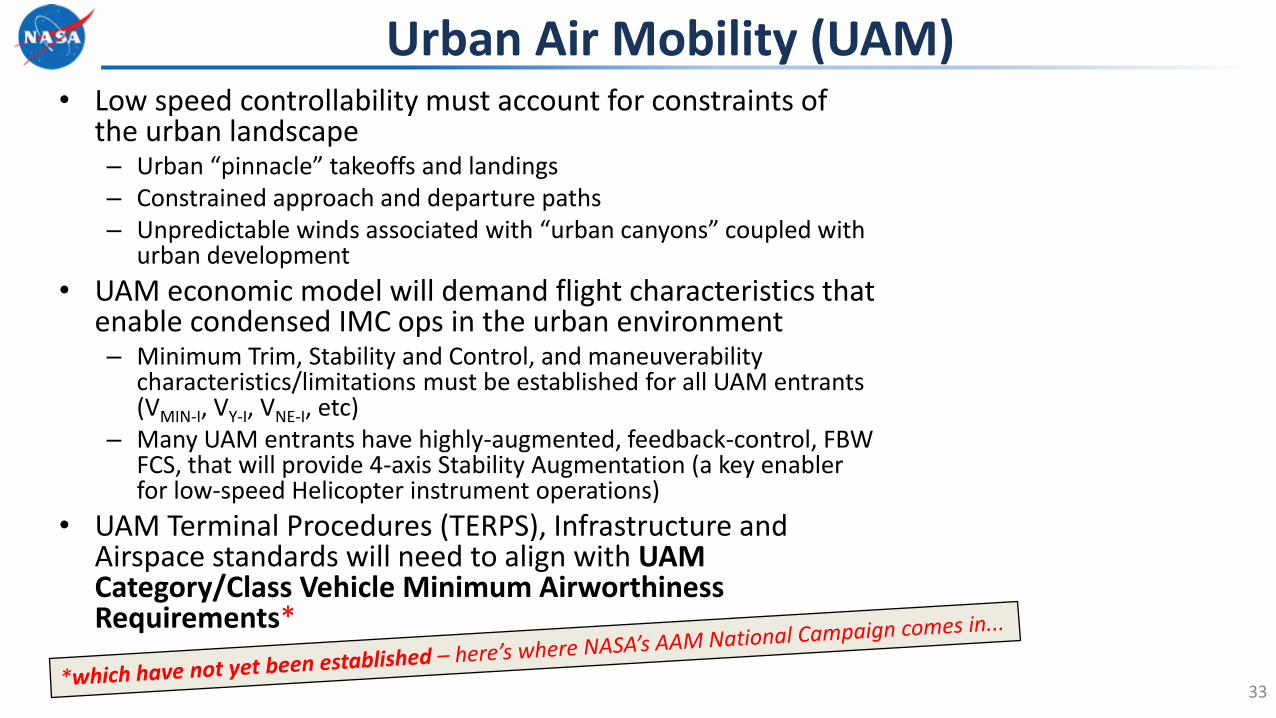
33
• Low speed controllability must account for constraints of the urban landscape– Urban “pinnacle” takeoffs and landings– Constrained approach and departure paths– Unpredictable winds associated with “urban canyons” coupled with
urban development
• UAM economic model will demand flight characteristics that enable condensed IMC ops in the urban environment– Minimum Trim, Stability and Control, and maneuverability
characteristics/limitations must be established for all UAM entrants (VMIN-I, VY-I, VNE-I, etc)
– Many UAM entrants have highly-augmented, feedback-control, FBW FCS, that will provide 4-axis Stability Augmentation (a key enabler for low-speed Helicopter instrument operations)
• UAM Terminal Procedures (TERPS), Infrastructure and Airspace standards will need to align with UAM Category/Class Vehicle Minimum Airworthiness Requirements*

Condensed UAM Approaches/Airspace– Viable UAM IMC approaches
– Heliport and Vertiport operations
AIRSPACE constraints
UAM key enablersMinimum Flight Characteristics required for Urban Operations– All Azimuth Capability
– Windward/Leeward effects on controllability
– Tailored UAM civil certification HQ tasks
VEHICLE minimum requirements
Required evolutions to existing standards to
enable UAM– Terminal/Instrument
Procedures (TERPS)
– Urban Planning
INFRASTRUCTURE needs

UAM Research QuestionsUsing a “Surrogate UAM” vehicle, the initial flight test plan endeavors to answer several UAM research questions:• Are existing Airplane and/or Rotorcraft FAA Subpart B
(stability, control, trim, and performance) airworthiness requirements appropriate for the UAM operational use case (aka, mission)?
• Can UAM vehicle designs deliver an aircraft that exhibits stability, control and performance that enables condensed, steep (nominal 9°), approaches, in Instrument Meteorological Conditions, into the expected UAM terminal environments?
• Are existing Heliport Design Criteria (dimensions, proximity to structures, and approach/departure surfaces) appropriate for the UAM mission? Can this criteria be reduced to further enable UAM goals?
35

UAM Task ElementsGround and Hover Tasks• Ground Handling/Taxi• Precision Hover• Lateral Reposition and Hold• Hover Turn and Hold• Pirouette• Vertical Reposition and Hold
Takeoff and Landing Tasks• Takeoff• Heliport and Vertiport Approach• Terminal Hover• Landing• Urban Landscape/Dynamic Interface• Decelerating Turn (RESERVED)
Transition Tasks• Deceleration IGE (Varied VAT)• Acceleration IGE/OGE (RESERVED)• Depart and Abort (RESERVED)• Simulated Failure (Approach/Departure) (RESERVED)• Balked Landing to Go-around
UAM Helicopter Flight Test PlanFAA “Subpart B” Vehicle CharacteristicsPerformance• Hover Power Margin (IGE/OGE) – free flight method• Level Flight• Climb/Descent/Glide
Flight Characteristics• Trimmed Flight Control Positions – Forward Flight• Critical All Azimuth Controllability• Maneuverability• Static Longitudinal Stability• Static Lateral/Directional Stability • Dynamic Stability
Approach/Departure Routes FIAPA (Flight Inspection Airborne Procedure Automation)
Integrated Scenarios Testing(Ops evaluation of an assumed UAM operation)
OtherPLASI CheckoutVIP sortie
Compare Results*
*OH-58C acts as an “experiment control”- known flying qualities deficiencies can help “tune”
developmental UAM (Handling Qualities) Task Elements
~25 hours –assuming ~1 hr
sortie length

37
Parameter Range Units
Airspeed 0 to 120 KIAS
Altitude 0 to 20,000 ft
N1 0 to 100 %
NR (Rotor RPM) 0 to 100 %
φ, Roll +/-80 °
Θ, Pitch Attitude +/-90 °
Ψ, Heading 0 to 360 °
P, Roll Rate +/-50 °/s
Q, Pitch Rate +/-50 °/s
R, Yaw Rate +/-50 °/s
Nx, fwd accel +/-8 g
Ny, side accel +/-8 g
Nz, normal accel +/-8 g
Static Pressure 0 to 15 PSI
Dynamic Pressure +/-2 PSICollective Control
Position 0 to 100 %
Lateral Control Position 0 to 100 %
Longitudinal Position 0 to 100 %
Directional Control
Position 0 to 100 %
Throttle Position 0 to 100 %
Torque 0 to 100 %
β, sideslip +/-90 °
OAT 0 to 100 ° C
Flight Research OH-58C instrumentation
VFTE IADS Display
• Aircraft provides all the necessary parameters for basic Flight Characteristics (S&C&P) evaluations

DATA PRODUCTS AND PROCESS WITH FAASarah Eggum – FAA Data Manager
Mohana Gurram– NASA Data Manager
38

Scenario Technical Working Group1
Trajectory Planning & Compliance
2Vehicle & AOM Data
Exchange & Coordination
3UAM Port
Operations
4Noise
Evaluations & Responses
Credits: NC STWG
Data Products & Processes with FAA
NASA I FAA Collaboration
Collaborative scenario development to test UAM operations for gap analysis
FAA UAM Focals
Anchor
NASA & FAA
National Campaign Working Group
Current Standards & Policies
Evolve
Identify Gaps
Credits: David Dunning, FAA NC Lead
AAM ImplementationPlan
Collaborative gap analysis for existing standards & policies across all FAA lines of business to enable UAM operations
ANG - NextGen
AGC – Office of the Chief Counsel
APL – Policy, International Affairs, and Environment
ARP - Airports
ASH – Security & Hazardous Materials Safety
AJO – Air Traffic Organization
TSI – Transportation Safety Institute
AVS – Aviation Safety
Data Requirements

Credits: NASA Ames ATI
Flight Test Infrastructure
Metrics discussed by influencers cannot be mapped back to data
captured during flight test.
FAA
NASA Research Projects
Industry Partners
GAP
NC Scenarios
ASTM Specifications
Airspace Test Infrastructure
Vehicle
Range
MOF
Test Plans
Data Ingestion
Data Storage
Data Models
Data Flows
Influencers
Spreadsheet
Data Needs and Requirements
Data Products & Processes with FAA
Approach to Data

Data Connections & Complexities
Data Products & Processes with FAA
Collections of Data
Credits: NC Data Team

QUESTIONS & WRAP UP
42

BACKUP
43

DAVID ZAHNNational Campaign Scalable UAM Operations Principal Investigator
44

6 AAM NC “UAM Heliports”• 40x40ft TLOF• Northern Heliports suitable for
wind/controllability studies• All Heliport design/placement IAW
AC 150/ 5390-2C Heliport Design
1 AAM NC “UAM Vertiport”• 1090ft length x 120ft width TLOF/FATO
• + + = Research Airport
• + + = Research Airport
• = Research Airport
01H 02H 03H
AAM NC Terminal Ops
01H
03H 02H
04H
05H06H
XEDW
XVPT04H 05H
19/01
19/01
XX33
06H

XEDW - 01H
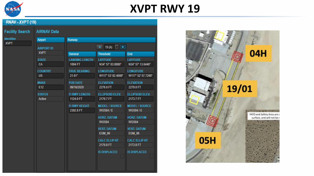
XVPT RWY 19

Flight Inspection Airborne Processor Application
48
• Ingests FAA AIRNAV data
• Ingests ARINC 424 for RNAV procedures
• Performs data quality checks
• Collects detailed data over runway threshold and runway end (e.g. HP Lat/Long, Rad Alt, IRU, air data, GNSS)
• Estimates the North, East, Up errors of the spatial data used for the procedure
• Logs all data for replay and/or analysis

49
NC Data Element CardExample UTE Test Sheet : Static
Research areas Airspace, Flight, and Infrastructure
Assign POC’s from NASA and FAA for Data Exchange
FAA POC’s delegated in areas of responsibility - Technical - Policy
Identify gaps in current criteria, standards, and regulations
Summarize suggestions for change

Spatial Data Integrity
Instrument Location Elevation Vertical Error (from Garmin)
Lateral Error(from Garmin)
Garmin Handheld Survey
(34 57 32.88 N, 117 52 54.07 W) 2274 ft. Most Accurate Most Accurate
Google Earth (34 57 32.84 N, 117 52 54.20 W) 2276 ft. +2 ft. (-0.04 degrees, .+0.13 degrees) 11.55 ft.249.50 True Bearing
TARGETS (34 57 32.69 N, 117 52 53.29 W) 2241 ft. -33 ft. (-0.19 degrees, - 0.78 degrees) 67.71 ft. 106.48 degrees True Bearing
SurveillanceBroadcastServices Monitor
(34 57 33.01 N, 117 52 53.97 W) 2280 ft. +6 ft. (+0.13 degrees, -0.10 degrees )15.56 ft. 32.34 True Bearing
FIAPA Pending Flight Data
Spatial Data Position Errors Area A – XEDW – 01H

AltitudeAGL (ft)
700
600
500
400
300
200
100
0
-1000 -500 0 500 1000 1500 2000 2500 3000 3500
Horizontal Distance (ft)
GPA 9°HCH 10ft
FAF70 KIAS
M
500
TDP
Vthreshold = ~0
TLOF ELEV
~3000
Quad Zero Approach
PinS
30kts
50kts
0kts
70kts
HMAS
HMAS
HMAS
750 m/s
TimeSpeed
Altitude

UAM Dep/App Theory Work Underway: Fusing data to apply to approach
Data Element Planning

NASA/FAA Flight following collaboration:
• Real time (1 sec refresh rate)
• Pilot deviations
• Route tracking and conformance
• Enforcement/Contingency Management
• Post flight data analysis
53
UAM Dep/App Theory

FAA’s Surveillance Broadcast Service Monitor Tool
54