aalborg universitet size effects on the bending behaviour
TRANSCRIPT
Aalborg Universitet
Size Effects on the Bending Behaviour of Reinforced Concrete Beams
Brincker, Rune; Henriksen, M. S.; Christensen, F. A.; Heshe, Gert
Published in:Minimum Reinforcement in Concrete Members
Publication date:1999
Document VersionPublisher's PDF, also known as Version of record
Link to publication from Aalborg University
Citation for published version (APA):Brincker, R., Henriksen, M. S., Christensen, F. A., & Heshe, G. (1999). Size Effects on the Bending Behaviour ofReinforced Concrete Beams. In A. Carpinteri (Ed.), Minimum Reinforcement in Concrete Members: ESISPublication 24 (pp. 127-137). Pergamon Press. European Structural Integrity Society Vol. 24
General rightsCopyright and moral rights for the publications made accessible in the public portal are retained by the authors and/or other copyright ownersand it is a condition of accessing publications that users recognise and abide by the legal requirements associated with these rights.
? Users may download and print one copy of any publication from the public portal for the purpose of private study or research. ? You may not further distribute the material or use it for any profit-making activity or commercial gain ? You may freely distribute the URL identifying the publication in the public portal ?
Take down policyIf you believe that this document breaches copyright please contact us at [email protected] providing details, and we will remove access tothe work immediately and investigate your claim.
Downloaded from vbn.aau.dk on: December 02, 2021

'l l i
' SIZE EFFECTS ON THE BENDING BEHAVIOUR OF
REINFORCED CONCRETE BEAMS
R. BRINCKER, M.S. HENRIKSEN, P.A. CHRISTENSEN and G. HESHE, Aalborg University, Sohngaardsholmsvej 57,
9000 Aalborg, Denmark
ABSTRACT
Load-deformation curves for reinforced concrete bcams subj ected to bending show size effects due to tensile failure of the concrete at early stages in the failure process and due to compression failure of the concrete when the final failure takes place. In this paper these effects are modelled using fradure mechanical concepts, and size effects of the models are studied and compared with experimental results.
KEYWORD S
Size effect, bending behaviour, reinforced concrete, minimum reinforcement, rotatianaJ capacity, fracture mechanics.
INTRODUCTION
The considered problem is the bending behaviour of simply supported concrete beams , Pigure l. The basic variables are the beam geometry given by the width b, the depth h and the span l , the concentrated load F acting at the middle of the beamand the corresponding dispiacement u .
The bending response of the beamis deseribed by the load-deflection curve, Pigure l , depicting the loading force F as a function of the dispiacement u.
It is assumed, that the parameters influencing the bending response of the beam, apart from the basic parameters mentianed above, are the concrete type deseribed by Young's Modulus E and the softening relations in tension and compression, the reinforcement type given by the stress-strain relation for the steel and the shear frietion stress r1 for the debonding, the reinforcement ratio <p,
the number ofre-bars n and the piacement of the re-bars as given by the distance heJ from the top of the beam. Note, that no softening relation is considered for the reinforcement. Thus, in this analysis, the contribution from necking of the re-bars , is neglected.
At early stages of the failure process, the response is gaverned by the tensile properties of the concrete, the elasti c properties of the reinforcement steel, and the debonding process between concrete and steel. Typically, the response will show a local force maximum F, where the concrete
127
l li l
'l
128 R. Brincker et al.
A: Test case t r D hi A
~
B: Response curue
F
u
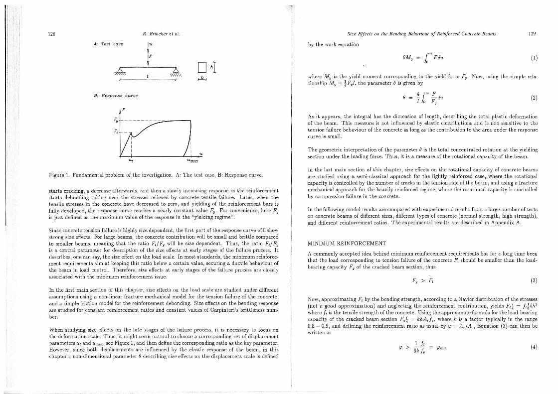
Figure l. Fundamental problem of the investigation. A: The test case, B: Response curve .
starts cracking, a decrease afterwards, and then a slowly increasing response as the reinforcement starts debonding taking over the stresses relieved by concrete tensile failure . Later, when the tensi le stresses in the concrete have decreased to zero, and yielding of the reinforcement bars is fully developed, the response curve reaches a nearly constant value Fy· For convenience, here Fy is just defined as the maximum value of the response in the "yielding regime".
Since concrete tension failure is higbly size dependent, the firs t part of the response curve w il! show strong size effects. For large beams, the concrete contribution wi ll be small and brittie compared to smaller beams, meaning t hat the ratio F,j Fy will be size dependent. Thus, the ratio F,j Fy is a central parameter for description of the size effects at early stages of the failure process. It describes, one can say, the size effect on the load scale. In most standards, the minimum reinforcement requirements aim at keeping this ratio below a certain value, securing a duetile behaviour of tbe beam in load control. Therefore, size effects at early stages of the fai lure process are closely associated with the minimum reinforcement issue.
In the first main section of this chapter, size effects on the load scale arestuelied under different assumptions using a non-linear fracture mechanical model for the tension failure of the concrete, and a simple frietion model for the reinforcement debonding. Size effects on th e bending response are stuelied for constant reinforcement ratios and constant values of Carpinteri 's brittleness number .
When studying size effects on the late stages of the failure process , il is necessary to focus on the deformation scale. Thus, i t might seem natura] to choose a corresponding set of dispiacement parameters u, and Umax, see Figure l, and then define the corresponding ratio as the key parameter. However, since both dispiacements are in:Buenced by the elastic response of the beam, in this chapter a non-dimensional parameter () clescribing size effects on the dispiacement scale is clefined
Size Effects on the Bending Behaviour of Reinforced Cone~·ete Beams 129
by the work equation
BMy = f "' Fdu (l)
where My is the yield moment corresponcling to the yield force Fy· Now, using the simple relationship My = ~Fyl, the parameter() is given by
41"' F e = - -du l o Fy
(2)
As it appears, the integral has the dimension of length, describing the total plastic deformation of the beam. This measure is not influenced by elastic contributions and is non-sensitive to the tension failure behavionr of the concrete as lang as the contribution to the area under the response curve is smal!.
The geometric interpretation of the parameter () is the total concentrated rotation at the yielding section under the loading force. Thus , it is a measure of the rotatianaJ capacity of the beam.
In the last main section of tilis chapter, size effects on the rotatianaJ capacity of concrete beams are stuelied using a semi-classical approach for the lightly reinforced case, where the rotational capacity is controlled by the number of cracks in the tension side of the beam, and using a fracture mechanical approach for the heavily reinforced regime, where the rotatianaJ capacity is controlled by compression failnre in the concrete.
In the foliowing model results are compared with experimental results from a large number of tests on concrete beams of different sizes, different types of concrete (normal strength, high strength) , and elifferen t reinforcement ratios . The experimental results are deseribed in Appendix A.
MINIMUM REINFORCEMENT
A commonly accepted idea behind minimum reinforcement requirements has for a lang time been that the load corresponding to tension failure of the concrete F, should be smaller than the loaclbearing capacity Fy of the cracked beam section, thus
(3)
Now , approximat ing F, by the bending strength, according to a Navier distribution of the stresses (not a good approximation) and negleeting the reinforcement contribution, yields F,~ = J,~bh2
where J, is the tensi le strengthof the concrete. Using the approximate formula for the load-bearing capacity of the cracked beam sect ion Fy~ = khA,jy , where k is a factor typically in the range 0.8- 0.9, and defining the reinforcement ratio as usual by <p = A,jA" Equation (3) can then be written as
l J, 'P >
6k fy lf>min {4)

130 R . Brincker el al.
This might be seen as the background for most minimum reinforcement requirements in the codes. The requirement states that, for a certain choice of steel and concrete, the reinforcement ratio should just be chosen larger than a certain value. This kind of classi cal reinforcement criteria are investigat.ed in detail in the foliowing subsect ion.
The weakness of t he classical kind of reinforcement criteria is the simplicity of the N a vier type of bending strength that does not inelude anysize effects. Thus, using the eriterion (4) in practice a value for the tension strength ft must be used that somehmv inelucles the size effect. Usually t his is done by using a value of the tensile strength estimated from bending tests on moderate size beams. A totally clifferent approach woulcl be to express a eriterion for stable crack growth across a reinforcecl concrete sect ion. Using linear fradure mechanics and some simplifications, this leaels to a er iterion of the type
(5)
where N p is Carpinteri 's briU!eness number for reinforced concrete
(6)
and where ](1c is the fraelure toughness of the concrete. In the second subsection, the eriterion given by (5) is investigated assuming that the fracture toughness can be approximated by I<1 c = JEGp.
Both the classical reinforcement eriterion given by Equation (4), and the fracture mechanical criterion given by Equation (5) are investigated by simulating the failure responses using a fictitious crack model for the concrete failure and a pure frietianaJ model for the reinforcement-concrete debonding, and finding the minimum values of the reinforcement ratio tp and the brittleness number N p corresponding to fulfilment of Equation (3).
Classical Requirernents for Minimum. Reinforcemenl.
The classical requirements for minimum reinforcement are investigated by simulating the failure response of beams of different size using a fictitious crack model for the concrete tension failure and a frietion model for the reinforcement-concrete debonding. Details of the investigation are given in Appendix B.
Three different concretes are considered: a normal strength concrete with linear softening , a normal strength concrete with bi-linear softening, and a high strength concrete with bi-linear softening . The softening relations are shown in Pigure 5 in Appendix B.
The size of the "valley" on the response curve aften seen in experimental results, occurring just after the local maximum F1 corresponding to the concrete tension failure, is totally controlled by the shear frietion stress r1. In the limit where the shear frietion stress becomes infinite, the response fo llows a. "master curve", and cases with a fini te shear frietion stress appea.r a.s deviations from this curve, Pigme LJ., Appendix B. In the simula.tions, the shea.r frietion stress was d10sen as T j == .j NI Pa for all cases, a. typica.l va.lue reported in !;he litera.ture for ribbed reinforcement.
Size Effecls on the Bending Behm•iour of Reinforced Concrete Beams 131
0.50 0.50 --+--- NSC (bi-linear softening)
___,._ NSC (linear softening)
0.40 0.40 HSC
-~ 0.30
~ 0.30
~ c E ~
0.20 '@ 0.20
~ 0.10 0.10
0.00 0.00
200 400 600 800 1000 o 200 400 600 800 1000 Beam depth [rrun) Beam depth [nm1]
Pigure 2. Reinforcement ratios corresponding to Fy = F1 for different beam sizes and different softening relations. Left: No initial crack. Right: Initial crack with a depth of 7.5 % of the beam depth.
Using the simulation model so defined, the minimum reinforcement ratio tp corresponding to the smallest ratio that satisfies the overall static requirement given by Equation (3) is detemuned for different beam sizes. The results are shown in Pigure 2. The diagrams show the results for two cases: the case of no initial crack, and the case where an initial crack is present with an initial depth of 7.5 % of the beam depth.
As it appears from the results, the reinforcement ratio corresponding to Fy = F1 is clearly dependent upon the size of the beam as well as the type of softening relation. The minimum reinforcement ratio (for this type of steel) is in range 0.20- 0.35 for very small beams reducing to 0.10- 0.20 for large beams. Purther, as expected , high strength concrete requires a higher minimum reinforcement than normal strength concrete, and a more duetile softening curve (the linear softening relation for the normal strength concrete has the same tensile strength and the same critical crack opening) requires a higher minimum reinforcement.
There is also an influence of the initial crack. As it appears, with an initial crack thc minimum reinforcement ratio is Jess sensitive to the type o f softening relation, and there is an overall tendency for the required minimum reinforcement ratio to become smaller. The presence of initial cracks does not seem to influence the size effect too much, although thereseems to be a littie Jess size effect in the case of initial cracks.
The overall result is that a unique minimum rcinforcement ratio is difficult to define since the ratio corresponding to Fy = F1 varies considerably. However , there are at least two important arguments in support of the simple eriterion :p> tpm.;n·
First, as the resu lts clearly indicate, if a. minimum reinforcement ratio tpm.;n has been detemuned from bending tests on smal! beams, it wi ll be on the safe side to use the eriterion <p > tpm.;n on
l l · l f l
i
132 R. Brintker et al.
0.50 0.50 --t- NSC (bi-linear softening)
------- NSC (linear softening)
0.40 0.40 1-ISC
0.30 0.30
0.20 0.20
0.10 0.10
o 200 400 600 800 l 000 o 200 400 600 800 1000 Beamdeptl1 [mm] Beamdeptl1 [mm]
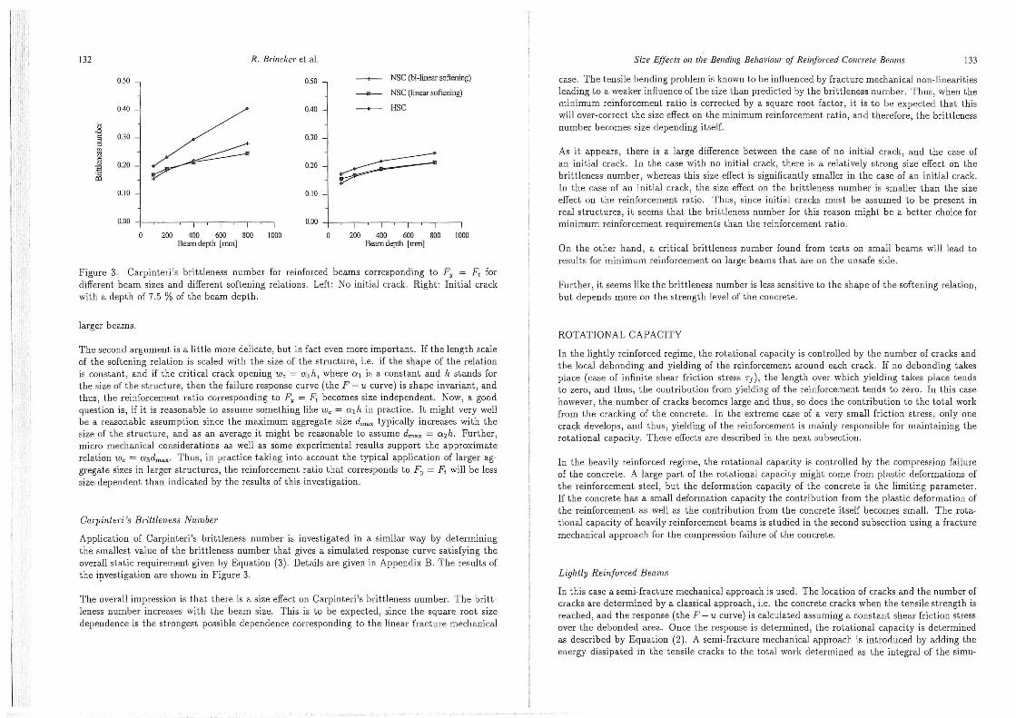
Figure 3. Carpinteri's brittleness number for reinforced bea.ms corresponding to Fy = F, for different beam sizes and different softening relations. Left: No initial crack. Right: Initial crack with a. depth of 7.5 % of the bea.m depth.
la.rger beams.
The second argument is a littie more delicate, but in faetevenmore importa.nt. If the length sca.le of the softening relation is sca.led with the size of the structure, i.e. if the shape of the relation is constant, and i f the critical crack opening w, = a1 h, where a 1 is a consta.nt and h stands for the size of the structure, then the fa.ilure response curve {the F- u curve) is shape invariant , and thus, the reinforcement ratio corresponding to Fy = F, becomes size independent. Now, a. good question is, if it is rea.sona.ble to assume something like w,= a 1 h in practice. It might very well be a reasonable assumption since the maximum aggregate size drnax typically increa.ses with the size of the structure, and a.s an average i t might be rea.sona.ble to assume drnax = azh. Further, micro mechanica.l considerations a.s well as some experimental results support the a.pproxima.te relation Wc = a 3 drnax· Thus, in practice taking into account the typical a.pplication of larger aggregate sizes in larger structures, the reinforcement ratio that corresponds to Fy = F, will be less size-dependent tha.n indicated by the results of this investigation.
Carpinteri 's Brittleness Number
Application of Carpinteri 's brittleness number is investigated in a similar way by determining tbe smallest value of the brittleness number that gives a simulated response curve satisfying the overall sta.tic requirement given by Equation {3). Details aregiven in Appendix B. The results of the i~vestigation a.re shown in Figure 3.
The overall impressionisthat there is a size effect on Carpinteri's brittleness number. The brittleness number increases with the beam size. This is to be expected, since the square root size depenclence is the strongest possible dependence corresponding to the linear fracture mechanical
Size Effecrs 011 rhe Be11di11g Belwviour of Reinforced Collo·ere Beams 133
case. The tensile bending problem is known to be influenced by fracture mechanical non-linearities leading to a weaker influence of the size than predicted by the brittleness number. Thus, w hen the minimum reinforcement ratio is corrected by a square root factor , it is to be expected that this will over-correct the size effect on the minimum reinforcement ratio, and therefore, the brittleness number becomes size depending itself.
As it appears, there is a large difference between the case of no initial crack , and the case of an initial crack. In the case with no initial crack, there is a relatively strong size effect on the brittleness number, whereas this size effect is significantly smaller in the case of an initial crack. In the case of an initial crack, the size effect on the brittleness number is smaller than the size effect on the reinforcement ratio. Thus, since initial cracks must be assumed to be present in real structures, it seems that the brittleness number for this reason might be a better choice for minimum reinforcement requirements than the reinforcement ratio.
On the other hand, a critica.l brittleness number found from tests on sma.ll bea.ms will lea.d to results for minimum reinforcement on large bea.ms that are on the unsafe side.
Further, it seems like the brittleness number is Jess sensitive to the shape of the softening relation , but depends more on the strength level of the concrete.
ROTATIONAL CAPACITY
In the lightly reinforced regime, the rotational capacity is controlled by the number of cracks and the loca.l debonding and yielding of the reinforcement araund ea.ch crack. If no debonding takes place (case of infinite shear frietion stress 'I), the length over which yielding talces place tencis to zero, and thus, the contribution from yielding of the reinforcement tencis to zero. In this case however , the number of cracks becomes large and thus, so does the contribution to the total work from the cracking of the concrete. In the extreme case of a very smal! frietion stress, only one crack develops , and thus , yielding of the reinforcement is ma.inly responsible for ma.intaining the rotational ca.pa.ci ty. These effects a.re descri bed in the next s u bsection.
In tbe heavily reinforced regime, tbe rota.tiona.l capacity is controlled by the compression failure of the concrete. A large part of the rotational capacity might come from plastic deformations of the reinforcement steel, but the deformation capacity of the concrete is the Jimiting parameter. If the concrete has a sma.ll deformation capacity the contribution from the plastic deformation of the reinforcement as well as the contribution from the concrete itself becomes smal!. The rotational capacity of heavily reinforcement beams is studied in the second subsection using a fracture mechanical approach for the compression failure of the concrete.
Light/y Reinforced Beams
In this case a. semi-fracture mechanical approach is used. The location of cracks and the number of cracks are determined by a cla.ssical approach, i.e. the concrete cracks w hen the tensile strength is reached, and the response (the F- u curve) is calculated assuming a constant shear frietion stress over the debonded area. Once the response is determined , tbe rotatianaJ capacity is determined as deseribed by Equation {2). A semi-fracture rnechanical approach is introduced by adding the energy dissipated in the tensile cracks to the tota.l work determined as the integral of the simu-

. ,, l ' 1 ~ ' ,, ~ ' (l
j . !l'
l ·;;i
' ;
\. '
l l l
l· l l
134 R. Brinc/rer et al.
lated response ( classical contribution). The energy dissipated in t b e tensile cracks is estimated as nAcGF where n is the number of cracks. Thus, the model assumes the cracks to be fu lly opened and the cracks to extend approximately over the w hole beam area Ae. Details are given in Appendix C.
Using a model like this, the ratalianal capacity is strongly dependent on the strain hardening of the reinforcement. If the strain hardening is smal!, yielding takes place only over a smal! length of the re-bars araund each crack , and the only way of extending the yield length of the re-bars, is to increase the strain hardening of the steel, i.e. the ratio f"/ /y where !u is the ultimate failure stress of the reinforcement . This cffeet is shown in Figure 3 in Appendix C.
A nother im porlant main result is that themodel does not show a so strong dependency o n t he shear frietion stress Tf as one would expect, Figure 4 in Appendix C. This is due to t he semi-fracture mechanical approach where the increasing values of Tf reduce the contribu t ion from yielding of the reinforcement, but at the same t ime increase the contribution from the energy dissipation in the tensile cracks.
Figure 4 shows the size effects for two elifferen l values of the shear fr ietion stress Tf. If the shear frietion stress has a smal! or moderate val u e (left part of Figure 4) then the number of cracks is moderate too, and the influence from the t ensile failure on the rotational capacity is smal!. In this case , the rotational capacity is dominated by the classical contributions from yielding and frictional debonding which does not show size effects , and thus , the size effect is smal!. However, if the shear frietion stress becomes large (right part of Pigure 4), the number of cracks increases, and so does the contribution to the rotational capacity from dissipation of energy in the tensile cracks. Thus, since this contribution is size dependent, the total rolational capacity becomes size dependent. As it appears from the results, the shear frieti on stress has to be very large in arder to enforce a size effect af importance, and even in t hat case, the size effeets are st ill moderate.
Figure 6 in Appendix C shows the rotatianaJ capacity for the two different ribbed reinforcement types used in the experimental invest igat ion, a high deformation capacity type, and a low deformation capacity type. In this case the shear friet ion stress is taken as T f = 5 M P a. As expeeted, size effeets are small for both types of reinforcement, and the deformation capacily of the reinforcement has a large influence on the rotational capacily of all beams .
Heavily Reinforced Beams
For this case a fradure mechanical descri ption of the compression failure is used. The main argument for this is that experimental results show that the post-peak behaviour includi ng the post-peak energy dissipation is relatively independent of the length of a compression speci men, see Pigure 2 in Appendix D.
Naturally, this leaels lo an assumption of localized compression failure, thus, compression failure is as~umed to take place over a certain length of the compression zone. This length is denaled the charaeteristic length lch· The characteristic length is assumed to be proportional to the depth of the compression zone corresponding to a compression-shear failure mode with the development of slip-planes at a certain angle lo horizontal. In this case the charaeteristic length becomes proportional lo the clepth hc of the compression zone lch = f3hc . Assuming an inel inabon a.ngle of the slip-planes si milar to t he cone-faiture of a cylinder in compression , justifies thc expectati on of (3 having a value araund 1.
0.50
0.40
~
u ~
0.30 Q"
u
c o
0 .2 0 o
"" 0.1 o
0.00
o o
Size Effects on the Bending Behaviour of Rein(orced Concrete BeanJS
0.2 11.4 O.o II .X ReinfurL'I.! Inl'll[ ralin re; l
I II
0.50
0.40
0.30
0 .2 0
0 .1 o
0.0 0
0.0
---+- 50x l0 0x l 200m m --- 100 x 200 x 2400 mm ---+-- 200 x 400 x 4800 mm --+-- 400 x 800 x 9600 mm
0.2 0.4 0.6 0.8 Rc inforc:e mcnt rati o [%1
1.0
135
Figure 4. Size effects on the rotational capaci ty in the light! y reinforced regime fo r elifferen t values of the shear frietion stress Tf. Left: Shear frietion stress Tf = 5 M P a. Right: Shear frietion stress Tf= 20 MPa.
Themodel assumes a simple linear softening relation, so themodel has two main parameters: the inelinabon parameter (3, and the criti cal deformation Wc of the concrete in the compression failure zone.
The model is roughly calibrated by simulating failure responses of beams, calculat ing the ratatianal capacity according to Equat ion (2) and comparing with the experimental results for normal strength concrete . It turns out that in arder to have reasonable agreement with the experimental results , the values of the key parameters of the model have to be chosen as W c ~ 4 mm, (3 ~ 8. These values are sarnewhat higher than expeeted, but the rather high valucs might be inlerpreted as a consequence of the loading arrangement for the tests where the loading plale used for distribution of the concentrated load might aet as confinement.
In Appendix D a simple model for tension failure of the reinforcement was inelucled in arder to check if the model showed a reasonable switch between concrete compression failure and reinforcement tension failure. Results for pure compression failure are shown in Pigure 5.
As it appears, the model shows a clear size effect on the rotatianaJ capacity, the rotatianaJ capacity becoming significantly smaller with increasing beam size. Further, for all beam sizes, the rotational capacity predicted by the model decreases with the reinforcement ratio. The influence from both the size and the reinforcement ratio is rather large. Thus, for high values of the reinforcement ratio, the rotatianaJ capacity is smal! for all bearn sizes, and for the large beams, the rotatianaJ capacity is smal! also for moderate values of the reinforcement ratio.
The results for the high strength concrete are obtained by using the samevalues of Wc and fJ as for

l· ,., " lp ,. P•'
~ ! . :H 'li ','
';; ;'''··
'· ' ,.
'
l l. : i ~
l ;;,
l l .
1',."
136 R. Brincker et al.
1.00 -+--- 50 x 100 x 1200 mm N orm al strengtil concrcte
100 x 200 x 2400 mm >.
u - 200 x 400 x 4800 mm Q. ~ u
0.50 _._ 400 x 800 x 9600 m m
c o
o
""
0.00
o .00 1.00 2.00 J .00 4.00 5.00 Reinforccmcnt rat io[% l
1.00 -+--- 50 x 100 x 1200 mm High streng ih concrctc
100 x 200 x 2400 mm >.
u 200 x 400 x 4800 mm Q.
u o .so -;;;
_._ 400 x 800 x 9600 m m c o ~
o
"'
0.00
0.00 l .00 2.00 3.00 4.00 5.00 Rcinforccmcnl ratio[%]
Pigure 5. Rotational capacity in the heavily reinforced regime. Top : Normal strength concrete. Bottom: High strength concrete.
~-------
Size Effects 011 the Bending Behaviour of Reinforced Concrete Beams 137
RotatianaJ capacity
Concrete compression fai lure Reinforcernent tension failure
Reimarcement ratio
Pigure 6. Combining models for lightly reinforced and heavily reinforced beams.
the normal strengt.h concrete; only the compression strength and the failure strain (peak strain) have been increased. For higher strength concrete, there is no guarantee, that the key parameters w c, f3 wi ll be the same. In faet , experimental results (see Appendix D) indicate lhat a smaller value of wc has to be used. However, keeping the key parameters the same, the results show a clear increase of the rotational capacity with strength.
The rotational capacity deseribed by themodel also depends weakly on the yield strength of the reinforcement just like the results of the model fo r the lightly reinforced regime deseribed in the preceding subsection depends weakly on the tensi le strengthof the concrete. However, considering the two models defined above, themodel for the lighlly rein[orced regime is describing rotational capacity mainly controlled by reinforcemenl lension failure, and the model for the heavi ly reinforced regime is describing rotatianaJ capacity mainly controlled by concrete compression failure. Now, Taking the smallest value of the rotatianaJ capacity predicted by the two models defines a model valid for all reinforcement ratios, the intersection point defining the transition from the failure mode where the rotational capacity is controlled mainly by reinforcemenl tensile properties to the fai lure mode where the rotanianaJ capacity is controlled mainly by concrete compression properties, see Pigure 6.