aalborg universitet power quality of grid-connected wind...
TRANSCRIPT

Aalborg Universitet
Power Quality of Grid-Connected Wind Turbines with DFIG and Their Interaction withthe GridSun, Tao
Publication date:2004
Document VersionPublisher's PDF, also known as Version of record
Link to publication from Aalborg University
Citation for published version (APA):Sun, T. (2004). Power Quality of Grid-Connected Wind Turbines with DFIG and Their Interaction with the Grid.Aalborg: Institut for Energiteknik, Aalborg Universitet.
General rightsCopyright and moral rights for the publications made accessible in the public portal are retained by the authors and/or other copyright ownersand it is a condition of accessing publications that users recognise and abide by the legal requirements associated with these rights.
? Users may download and print one copy of any publication from the public portal for the purpose of private study or research. ? You may not further distribute the material or use it for any profit-making activity or commercial gain ? You may freely distribute the URL identifying the publication in the public portal ?
Take down policyIf you believe that this document breaches copyright please contact us at [email protected] providing details, and we will remove access tothe work immediately and investigate your claim.
Downloaded from vbn.aau.dk on: juni 15, 2018
Power Quality of Grid-Connected Wind Turbines with DFIG
and Their Interaction with the Grid
by
Tao Sun
Dissertation submitted to the Faculty of Engineering & Science at Aalborg University in partial fulfilment of the requirements for the degree of
Doctor of Philosophy in Electrical Engineering
Institute of Energy Technology Aalborg University, Denmark
May 2004

Aalborg University Institute of Energy Technology Pontoppidanstraede 101 DK-9220 Aalborg East Copyright © Tao Sun, 2004 ISBN 87-89179-49-8

III
Preface
This thesis is submitted to the Faculty of Engineering and Science at Aalborg University in partial fulfilment of the requirements for the Ph.D. degree in Electrical Engineering. The research has been conducted at the Department of Electrical Energy Conversion which is part of the Institute of Energy Technology, Aalborg University.
Four supervisors have followed the project: Professor Zhe Chen, Professor Frede Blaabjerg, both from the Institute of Energy Technology, Aalborg University, Professor Huizhu Dai, from China Electric Power Research Institute, and Professor Yihan Yang, from North China Electric Power University. I would like to thank all of them for their support and advices to my work during the entire project period and especially, Prof. Zhe Chen for the inspiration, encouragement and precious comments.
The Institute of Energy Technology, Aalborg University, has funded the major part of the research leading to this thesis. This funding has been vital for this research project. I would like to express my gratitude to Professor Frede Blaabjerg, for providing me the precious chance of carrying out the whole project in the Institute of Energy Technology, Aalborg University.
Before I came to Aalborg University, I studied as a Ph.D. candidate in China Electric Power Research Institute in Beijing, China. During that time, I gained valuable knowledge, ideas, and inspiration from all the colleagues in the research group. I am very grateful to all of them, especially Professor Weisheng, Wang, for many fruitful, spirited discussions.
My colleagues at the Institute of Energy Technology, Aalborg University are all given thanks for their help during this research project.
Finally, I owe special thanks to my whole family and my girlfriend, Li Fan, for their patience with me in the periods where I have been apart from them. May 2004, Aalborg Tao Sun

IV

V
Abstract
Institutional and governmental support on wind energy sources, together with the wind energy potential and improvement of wind energy conversion technology, has led to a fast development of wind power generation in recent years. The continuous increase of the wind power penetration level brings a result that wind power generation gradually becomes an important component of power generation in the grid, which makes the study on the wind power quality issues and the interaction between the wind turbines and the grid necessary and imperative.
The research documented in this thesis examines power quality issues of grid-connected wind turbines and the interaction between wind turbines and the grid. The specific goal of the research has been to investigate flicker emission and mitigation of grid-connected wind turbines with doubly fed induction generators (DFIG) during continuous operation, and voltage recovery of such kind of grid-connected wind turbines after the clearance of a short circuit fault in the grid.
As a basis of the research, a model of grid-connected wind turbines with DFIG is developed in the dedicated power system analysis tool PSCAD/EMTDC, which simulates the dynamics of the system from the turbine rotor, where the kinetic wind energy is converted to mechanical energy, to the grid connection point where the electric power is fed into the grid. The complete grid-connected wind turbine model includes the wind speed model, the aerodynamic model of the wind turbine, the mechanical model of the transmission system, models of the electrical components, namely the DFIG, PWM voltage source converters, transformer, capacitor, and the control system. The grid model and the electrical components of the wind turbine are built with standard electrical component models from PSCAD/EMTDC library. The wind model, the aerodynamic model, the mechanical model and the control system are built with custom components developed in PSCAD/EMTDC.
Two control schemes are implemented in the developed grid-connected wind turbine model: speed control and pitch control. The speed control scheme is composed by two vector-control schemes designed respectively for the rotor-side and grid-side PWM voltage source converters. Cascade control is used in the vector-control schemes. Two design methods, pole-placement and internal model control, are applied for designing the PI-controllers in the vector-control schemes. The pitch control scheme is employed to regulate the aerodynamic power from the turbine. The performances of the control schemes, respectively current control loops, power control loops, DC-link voltage control loop and pitch control loop, are illustrated, which meet the design requirements. Simulation results show that the wind turbine is capable of providing satisfactory steady state and dynamic performances, which makes it possible that the wind turbine model can be applied to study the power quality issues of such kind of grid-connected wind turbines and their interaction with the grid.
To evaluate the flicker levels produced by grid-connected wind turbines with DFIG, a flickermeter model is developed according to the IEC standard IEC 61000-4-15, which simulates the response of the lamp-eye-brain chain and provides on-line statistical analysis of
VI Abstract
the flicker signal and the final results. Based on the developed model of grid-connected wind turbines with DFIG and the flickermeter model, the flicker emission during continuous operation is studied. The influence factors that affect flicker emission of grid-connected DFIG wind turbines, such as wind characteristics (mean speed, turbulence intensity) and grid conditions (short circuit capacity, grid impedance angle) are analysed. The effects of the influence factors are compared with previous research results related to the fixed speed wind turbine. In particular, the effects of mean wind speed, turbulence intensity and grid impedance angle are different from that in the case of the fixed speed wind turbine.
It is possible to regulate the reactive power flow on the connection line so that the voltage fluctuation caused by the active power flow can be compensated by that caused by the reactive power flow. Based on this principle, two effective measures are proposed to mitigate the flicker levels produced by grid-connected wind turbines with DFIG, respectively by wind turbine output reactive power control and using STATCOM. Simulation results demonstrate that these two measures are effective for flicker mitigation regardless of mean wind speed, turbulence intensity and short circuit capacity ratio.
The voltage recovery study is started with grid-connected wind turbines with dynamic slip control, which are simple, cost-effective, partially variable speed wind turbines, for gaining a good understanding of transient responses of induction generators in an external short-circuit situation. The model of a variable speed wind turbine with dynamic slip control in the simulation tool of PSCAD/EMTDC is presented, and the control schemes, respectively dynamic slip control and pitch control, are described. The transient process of grid-connected wind turbines after an external short-circuit fault is analyzed in detail. It is concluded from the analysis that increasing the electromagnetic torque or decreasing the aerodynamic torque helps to recover the voltage after the clearance of an external short-circuit fault. For the wind turbine with dynamic slip control, after the clearance of an external short-circuit fault, the electromagnetic torque may be strengthened by adjusting the generator slip, and the aerodynamic torque may be reduced by regulating the pitch angle, which helped to slow the rotor speed down and re-established the voltage at the wind turbine terminal. Simulation results demonstrate that pitch control, dynamic slip control and combined control are effective measures for voltage recovery of grid-connected wind turbines with dynamic slip control. An emergency pitch regulation scheme is developed and applied in the case of pitch control.
Based on the acquired knowledge, the voltage recovery of grid-connected wind turbines with DFIG is studied. Two kinds of situations are studied which depend on whether the rotor protection devices in the DFIG are triggered or not.
When the situation after an external short-circuit fault is not serious enough to trigger the rotor protection devices, the control schemes of the DFIG operated as normal and are capable of forcing the rotor speed down and re-establishing the voltage at the wind turbine terminal after the clearance of the short-circuit fault, which are demonstrated by simulation results. The performances of the wind turbine as well as the control schemes are illustrated in detail.
If the situation after an external short-circuit fault is serious enough, the protection devices in the rotor circuit will be triggered which yields a result that the generator rotor is short-circuited and the rotor-side converter is deactivated. In this situation, a control strategy is proposed to re-establish the voltage at the wind turbine terminal and restore the wind turbine’s normal operation after the fault clearance, which is verified by simulations results. The control strategy, which takes advantage of the benefits of the rotor circuit protection device and the emergency pitch control scheme, are performed in three steps, respectively protection device activation, voltage recovery assisted by pitch control, and normal operation restoration of the wind turbine with DFIG.

VII
Contents
Preface III Abstract V
Part I Preliminaries 1
1 Introduction ... 3 1.1 Background and motivation.......................................................................................... 3
1.2 Literature study ............................................................................................................. 6 1.2.1 Flicker ................................................................................................................ 7 1.2.2 Voltage recovery................................................................................................ 8 1.3 Problem statement......................................................................................................... 9 1.4 Outline of the thesis ..................................................................................................... 10 Bibliography ........................................................................................................................ 12
Part II Modelling and control of grid-connected wind turbines with DFIG ............................................................................ 17
2 Model of grid-connected wind turbines with DFIG . 19 2.1 Introduction.................................................................................................................. 19 2.2 Wind model.................................................................................................................. 21 2.2.1 Park scale wind model ...................................................................................... 22 2.2.2 Rotor wind model ............................................................................................. 22 2.3 Aerodynamic model..................................................................................................... 23 2.3.1 Power extraction from the air stream................................................................ 23 2.3.2 Aerodynamic model.......................................................................................... 24 2.3.3 Aerodynamic power control ............................................................................. 26 2.4 Mechanical model........................................................................................................ 26 2.5 DFIG model ................................................................................................................. 27 2.5.1 Steady state equivalent circuit .......................................................................... 27 2.5.2 Operation principle ........................................................................................... 28 2.5.3 Dq-model in the arbitrary reference frame ....................................................... 30 2.5.4 Dq-Model in the Rotor Fixed Reference Frame ............................................... 33 2.6 PWM voltage source converter model......................................................................... 34 2.7 Summary ...................................................................................................................... 36 Bibliography ........................................................................................................................ 37

VIII Contents
3 Control schemes and performance of grid-connected wind turbines with DFIG .. 39 3.1 Speed control scheme .................................................................................................. 40 3.1.1 Vector-control scheme of grid-side PWM voltage source converter................ 41 3.1.2 Vector-control scheme of rotor-side PWM voltage source converter .............. 44 3.1.3 PI-controller design........................................................................................... 47 3.2 Pitch control scheme .................................................................................................... 52 3.3 Performance of the wind turbine.................................................................................. 54 3.3.1 Wind turbine description................................................................................... 54 3.3.2 Wind simulation................................................................................................ 57 3.3.3 Performances of the control schemes ............................................................... 58 3.3.4 Performance of the wind turbine....................................................................... 63 3.4 Summary ...................................................................................................................... 67 Bibliography ........................................................................................................................ 70
Part III Flicker emission and mitigation of grid-connected wind turbines with DFIG 73
4 Flicker emission of grid-connected wind turbines with DFIG .. 75 4.1 The reason of flicker .................................................................................................... 76 4.2 Flickermeter model ...................................................................................................... 76 4.3 Flicker emission of grid-connected wind turbines with DFIG .................................... 79 4.4 The influence factors of flicker.................................................................................... 81 4.4.1 Mean wind speed .............................................................................................. 81 4.4.2 Turbulence intensity.......................................................................................... 82 4.4.3 Short circuit capacity ratio ................................................................................ 84 4.4.4 Grid impedance angle ....................................................................................... 85 4.5 Summary ...................................................................................................................... 86 Bibliography ........................................................................................................................ 87 5 Flicker mitigation of grid-connected wind turbines with DFIG . 89 5.1 The principle ................................................................................................................ 89 5.2 Flicker mitigation by control of wind turbine output reactive power.......................... 90 5.3 Flicker mitigation using STATCOM........................................................................... 95 5.3.1 Simplified model of PWM voltage source converter ....................................... 95 5.3.2 Control scheme for STATCOM........................................................................ 96 5.3.3 Flicker mitigation using STATCOM................................................................ 99 5.4 Summary .....................................................................................................................104 Bibliography .......................................................................................................................104
Part IV Voltage recovery of grid-connected wind turbines at an external short-circuit fault 107
6 Voltage recovery of grid-connected wind turbines with dynamic slip control ..109 6.1 Modelling and control of grid-connected wind turbines with dynamic slip control...110 6.1.1 Wind turbine model .........................................................................................110 6.1.2 Control schemes...............................................................................................111 6.2 Transient analysis........................................................................................................113

Contents IX
6.3 Voltage recovery of grid-connected wind turbines with dynamic slip control...........113 6.3.1 Voltage recovery assisted by pitch control ......................................................114 6.3.2 Voltage recovery assisted by dynamic slip control..........................................116 6.3.3 Voltage recovery assisted by combined control ..............................................117 6.4 Summary .....................................................................................................................117 Bibliography .......................................................................................................................121 7 Voltage recovery of grid-connected wind turbines with DFIG .123 7.1 Studied system ............................................................................................................123 7.2 Transient analysis of the post-fault process ................................................................125 7.2.1 During the fault ................................................................................................125 7.2.2 After the clearance of the fault.........................................................................126 7.3 Control strategy for voltage recovery .........................................................................129 7.3.1 Protection device activation.............................................................................129 7.3.2 Voltage recovery..............................................................................................131 7.3.3 Normal operation restoration ...........................................................................132 7.3.4 A simulation case with high wind speeds ........................................................132 7.4 Summary .....................................................................................................................134 Bibliography .......................................................................................................................134
Part V Conclusion 137
8 Conclusion .139 8.1 Summary of the thesis.................................................................................................139 8.2 Conclusions and new contributions ............................................................................141 8.3 Future work.................................................................................................................143
Part VI Appendices 145
A Wind turbine model in PSCAD/EMTDC 147 A.1 Introduction...............................................................................................................147 A.2 Turbine ......................................................................................................................148 A.3 DFIG .........................................................................................................................149 A.4 PWM voltage source converter.................................................................................149 A.5 Grid- and rotor-side PWM converter control blocks ................................................150 Bibliography ......................................................................................................................151 B System parameters 153 C Complete reference list 155 D Published papers 161

X Contents

Part I
Preliminaries


3
Chapter 1
Introduction
The research documented in this thesis relates to power quality issues of grid-connected wind turbines and the interaction between wind turbines and the grid that they are connected to. In particular, this work concentrates on flicker emission and mitigation of grid-connected wind turbines with doubly fed induction generators (DFIG) during continuous operation, and voltage recovery of such kind of grid-connected wind turbines after the clearance of a short circuit fault in the grid.
The background and the motivation for the research are presented in this chapter, as well as a study on the previously published relevant research work. Also, the problem statement is given and an outline of the individual chapters concludes the chapter.
1.1 Background and motivation Rising pollution levels and worrying changes in climate, arising in great part from energy-
producing processes, demand the reduction of ever-increasing environmentally damaging emissions. Additionally an emerging awareness of finiteness of the earth’s fossil fuel reserves has caused many people to look for alternatives. Generating electricity, particularly by making use of renewable resources, allows the attainment of notable effects. Thereby the immense potentials of wind energy on the earth assume great importance. The worldwide potential of wind power means that its contribution to electricity production can be of significant proportions. In many countries, the potential for wind energy production exceeds by far the local consumption of electricity. Good prospects and economically attractive expectations for the use of wind power are indivisibly linked to the incorporation of this weather-dependent power source into existing power systems.
In the past decades, the wind power generation has experienced a very fast development. Table 1.1 shows the installed wind turbine capacity worldwide at the end of 2002 [1], although it is obvious that with such a rapid growth in some countries data of this kind become out of date very quickly.
The reasons that resulted in the fast development of wind power are quite complex. Important factors include the immense potentials of wind energy on the earth, the political and economic support from the governments and the development of wind turbine technology.

Power quality of grid-connected wind turbines with DFIG and their interaction with the grid 4
Table 1.1 Installed wind turbine capacity throughout the world, the end of 2002 [1]
Location Installed capacity (MW) USA 4,685
Canada 238 North America 4,923
Germany 12,001
Spain 4,830 Denmark 2,880
Italy 785 Netherlands 688
UK 552 EU Total 23,056
Other Europe 235
India 1,702 China 468 Japan 415
Other Total 2,914
World Total 31,128 Wind turbine technology, dormant for many years, awoke at the end of the 20th century to
a world of new opportunities. Developments in many other areas of technology were adapted to wind turbines and have helped to hasten their quick emergence. A few of the many areas which have contributed to the new generation of wind turbines include materials science, aerodynamics, power electronics, computer science, testing and analytical methods.
The main options in wind turbine design and construction include [2]:
• axis of rotation: horizontal or vertical
• number of blades (commonly two and three)
• rotor orientation: downwind or upwind of tower
• blade material, construction method, and profile
• hub design: rigid, teetering or hinged
• power control via aerodynamic control (stall control) or variable pitch blades (pitch control)
• fixed or variable rotor speed
• orientation by self-align action (free yaw), or direct control (active yaw)
• synchronous or induction generator
• gearbox or direct drive generator
Today, the most common design of wind turbine is the horizontal axis, three-bladed, upwind wind turbine.
Chapter 1. Introduction
5
Wind turbines can either operate at fixed speed or variable speed. Compared with fixed speed operation, variable speed operation has a number of benefits including the reduction of wear and tear on the wind turbine and potential operation of the wind turbine at maximum efficiency over a wide range of wind speeds, yielding increased energy capture [2].
The benefits are listed in detail as follows [3]:
• below rated wind speed, the rotor speed can be made to vary with wind speed to maintain peak aerodynamic efficiency.
• the reduced rotor speed in low winds results in a significant reduction in aerodynamically-generated acoustic noise – noise is especially important in low winds, where ambient wind noise is less effective at masking the turbine noise.
• the rotor can act as a flywheel, smoothing out aerodynamic torque fluctuations before they enter the drive train – this is particularly important at the blade passing frequency.
• direct control of the air-gap torque allows gearbox torque variations above the mean rated level to be kept very small.
• both active and reactive power can be controlled, so that unity power factor can be maintained – it is even possible to use a variable speed wind farm as a source of reactive power to compensate for the poor power factor of other consumers on the network; variable speed turbines will also produce a much lower level of electrical flicker.
Most of the major wind turbine manufacturers are developing new larger wind turbines. These wind turbines are all based on variable speed operation with pith control. Three main types of variable speed wind turbine are illustrated as follows [4]:
• wind turbines equipped with squirrel cage induction generator, connected to the grid through a stator converter cascade
• wind turbines equipped with DFIG, connected to the grid through a rotor converter cascade
• wind turbines equipped with synchronous generator and a stator DC-link cascade for network connection
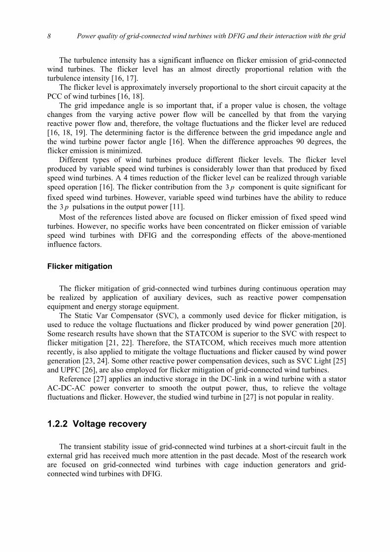
Nowadays, DFIG are most commonly used by the wind turbine industry for larger wind turbines [5]. The most significant reason for the popularity of DFIG is the relatively small size of power converter – approximately 10-25% of nominal turbine power – which is a cost efficient solution in order to obtain variable speed [6]. The acknowledgement of the increasing installed capacity of grid-connected wind turbines with DFIG is the background for this research work. Fig. 1.1 shows the block diagram of a grid-connected wind turbine with DFIG, where PCC represents the Point of Common Coupling.
As the wind power generation, which depends on the weather, is integrated into the grid continuously and quickly, the influence of wind turbines on the grid power quality is becoming an important issue, especially the influence on voltage fluctuation and flicker. Flicker is defined as “an impression of unsteadiness of visual sensation induced by a light stimulus, whose luminance or spectral distribution fluctuates with time”[7], which can cause consumer annoyance and complaint. Furthermore, flicker can become a limiting factor for integrating wind turbines into weak grids, and even into relatively strong grids where the wind power penetration levels are high.

Power quality of grid-connected wind turbines with DFIG and their interaction with the grid 6
As mentioned above, variable speed operation of the rotor has the advantage that the faster
power variations are not transmitted to the grid but are smoothed by the flywheel action of the rotor, and will also produce a much lower level of electrical flicker in the grid. Even though, the prospect of achieving a better understanding of the flicker produced by grid-connected wind turbines with DFIG is one basic motivation for this research work, which will benefit integrating more wind power generation into the existing grid.
The continuous increase of the wind power penetration level brings a result that wind power generation gradually becomes an important component of power generation in the grid, which makes the study on the interaction between the wind turbines and the grid necessary and imperative, especially in some critical situations like short-circuit faults, voltage dips, etc.
The system operators, who are responsible for maintaining power system stability and reliable power supply, have formulated specifications regarding grid integration of wind power generation. According to the specification in Denmark [8], at a short-circuit fault in the external grid, the voltages at the wind turbine terminals should be re-established after the fault clearance without any power loss caused by disconnection of wind turbines. The similar requirements can be found in the specifications in Germany, the Netherlands, England and Wales [9]. The reason is, when the wind power penetration level is high, the protective disconnection of a large amount of wind power will be an unacceptable consequence that may threaten the power system stability.
To investigate the voltage recovery issue of grid-connected wind turbines with DFIG after the clearance of an external short-circuit fault is another basic motivation for this research work.
1.2 Literature study As the installed capacity of grid-connected wind turbines increased continuously and
rapidly in recent years, the power quality issues of grid-connected wind turbines and the interaction between the wind turbines and the grid have attracted considerable interest. This has resulted in a numerous scientific papers and reports, which are mainly from academia. An in-depth review of this prior work will become quite voluminous and, therefore, only the main contributions, which are tightly related to the flicker produced by grid-connected wind turbines during continuous operation and the voltage recovery issue of grid-connected wind turbines, are outlined and commented.
Turbine
DFIG TransformerGearbox
3
3 3
3
Powerconverter
GridPCC
Z
Figure 1.1 Block diagram of a grid-connected wind turbine with a DFIG.
Chapter 1. Introduction
7
1.2.1 Flicker
The reason of flicker Grid-connected wind turbines may have considerable fluctuations in the output power, as
the wind is a weather-dependent power source. Reference [10] indicates that the grid suffers voltage fluctuations and flicker as the wind turbines’ output power, which flows into the grid, varies.
The flicker produced by grid-connected wind turbines during continuous operation is mainly caused by fluctuations in the output power due to wind speed variations, the wind gradient and the tower shadow effect [11]. As a consequence of the combination of wind speed variations, the wind gradient and the tower shadow effect, an output power drop will appear three times per revolution for a three-bladed wind turbine. This frequency is normally referred to as p3 . For fixed speed wind turbines with induction generators, power pulsations up to 20% of the average power at the frequency of p3 will be generated [12].
The tower shadow effect is produced because the wind turbine tower offers resistance to the wind flow, and it disturbs the wind flow both upstream and downstream. Far from the tower influence, the wind speed is unchanged, while it increases when approaching the tower and decreases when coming closer. A Fourier series with harmonic multiples of p3 frequency can represent this shadow effect [13]. The tower shadow effect is more important to the wind turbines having their blades downwind of the tower.
The wind shear phenomenon also produces torque oscillations caused by the wind speed gradient along the height of the area swept by the blades. The wind speed gradient may be described in polar coordinates centred at the hub elevation by the binomial series [13]. As the rotor samples the incoming wind, it sees the wind profiles as a periodical varying function of the time with harmonic multiples of p3 frequency.
The output power of grid-connected wind turbines have been analysed in the frequency domain [14, 15]. The results show that, in addition to the dominating periodic component p3 , the p6 , p9 , p12 and p18 components are visible too. A possible reason for the existence of the p1 component is that the rotor may be unbalanced. Another possibility is that one of the blades produces a higher torque than the other ones. The tower resonance frequency is also detectable which is assumed originating from a side-ways oscillation of the turbine.
Influence factors
There are numerous of factors that affect flicker emission of grid-connected wind turbines during continuous operation, such as wind characteristics (e.g. mean wind speed, turbulence intensity), grid conditions (e.g. short circuit capacity, grid impedance angle) and types of wind turbines (e.g. fixed speed, variable speed).
The flicker level increases at higher wind speeds due to higher turbulence in the wind. For fixed speed wind turbines, the flicker level increases around three times from lower to higher wind speeds. For variable speed wind turbines, the flicker level increases with a rise in the wind speed, until the wind speed reaches its rated value. As the wind turbine reaches its rated power, the variable speed system will smooth out the power fluctuations and, thereby, limit the flicker [11].
Power quality of grid-connected wind turbines with DFIG and their interaction with the grid 8
The turbulence intensity has a significant influence on flicker emission of grid-connected wind turbines. The flicker level has an almost directly proportional relation with the turbulence intensity [16, 17].
The flicker level is approximately inversely proportional to the short circuit capacity at the PCC of wind turbines [16, 18].
The grid impedance angle is so important that, if a proper value is chosen, the voltage changes from the varying active power flow will be cancelled by that from the varying reactive power flow and, therefore, the voltage fluctuations and the flicker level are reduced [16, 18, 19]. The determining factor is the difference between the grid impedance angle and the wind turbine power factor angle [16]. When the difference approaches 90 degrees, the flicker emission is minimized.
Different types of wind turbines produce different flicker levels. The flicker level produced by variable speed wind turbines is considerably lower than that produced by fixed speed wind turbines. A 4 times reduction of the flicker level can be realized through variable speed operation [16]. The flicker contribution from the p3 component is quite significant for fixed speed wind turbines. However, variable speed wind turbines have the ability to reduce the p3 pulsations in the output power [11].
Most of the references listed above are focused on flicker emission of fixed speed wind turbines. However, no specific works have been concentrated on flicker emission of variable speed wind turbines with DFIG and the corresponding effects of the above-mentioned influence factors.
Flicker mitigation
The flicker mitigation of grid-connected wind turbines during continuous operation may be realized by application of auxiliary devices, such as reactive power compensation equipment and energy storage equipment.
The Static Var Compensator (SVC), a commonly used device for flicker mitigation, is used to reduce the voltage fluctuations and flicker produced by wind power generation [20]. Some research results have shown that the STATCOM is superior to the SVC with respect to flicker mitigation [21, 22]. Therefore, the STATCOM, which receives much more attention recently, is also applied to mitigate the voltage fluctuations and flicker caused by wind power generation [23, 24]. Some other reactive power compensation devices, such as SVC Light [25] and UPFC [26], are also employed for flicker mitigation of grid-connected wind turbines.
Reference [27] applies an inductive storage in the DC-link in a wind turbine with a stator AC-DC-AC power converter to smooth the output power, thus, to relieve the voltage fluctuations and flicker. However, the studied wind turbine in [27] is not popular in reality.
1.2.2 Voltage recovery
The transient stability issue of grid-connected wind turbines at a short-circuit fault in the
external grid has received much more attention in the past decade. Most of the research work are focused on grid-connected wind turbines with cage induction generators and grid-connected wind turbines with DFIG.
Chapter 1. Introduction
9
Reference [28] illustrates in detail the transient process of grid-connected wind turbines with induction generators at a short-circuit fault in the external grid. There are numerous of factors that influence the transient stability of grid-connected wind turbines with induction generators at an external short-circuit fault. The research work in [29] examines the effects of wind turbine shaft stiffness, mass moment of inertia of the wind turbine and generator rotor, length of the interfacing line, nominal voltage level of the interfacing line, wind turbine operating power factor, and the type of fault. References [30, 31] illustrate the influences of wind turbine mechanical parameters on the transient stability. In [32], the influences of grid short-circuit capacity, X/R ratio, fault type, and wind turbine power factor correction on the transient stability are demonstrated. The effects of wind speed, wind turbine mechanical parameters, reactive power compensation, and grid short-circuit capacity are shown in [33].
Regarding the improvement of transient stability of grid-connected wind turbines with induction generators at an external short-circuit fault, [25, 31, 34] applies different measures, such as adjustment of wind turbine protective relay settings, using the control ability of wind turbines, dynamic reactive compensation, to re-establish the wind turbine terminal voltage after the fault clearance. Reference [32] proposes several measures to help recovering the wind turbine terminal voltage after the fault clearance, such as increasing the generator electrical torque, reducing the turbine mechanical torque, dynamic reactive compensation, and controlling the wind turbine active power. However, the paper does not provide the effects of the proposed measures.
Grid-connected wind turbines with DFIG have shown better behaviours concerning transient stability at short-circuit faults in the external grid in comparison with wind turbines with cage induction generators [33, 35, 36]. Reference [37] analyses the transient process of grid-connected wind turbines with DFIG at a short-circuit fault in the external grid. However, this paper does not discuss the improvement of transient stability and the voltage recovery after the fault clearance. Reference [38] studies the transient process of grid-connected wind turbines with DFIG at an external short-circuit fault, and applies two measures to improve the transient stability and re-establish the wind turbine terminal voltage after the fault clearance. The applied two measures are respectively regulating the parameters of control schemes and fast-acting reactive power control. However, in this paper the DC-link voltage is assumed to be constant during the transient process, which will bring a discrepancy into the research results.
1.3 Problem statement Although many research works, as mentioned in the literature study, have been carried out
on flicker emission and mitigation of grid-connected wind turbines during continuous operation, no special works are systematically concentrated on flicker emission and mitigation of grid-connected wind turbines with DFIG, one of the most popular wind turbines worldwide. To have a good understanding of the flicker produced by grid-connected wind turbines with DFIG during continuous operation may benefit the development of wind power generation. Furthermore, based on the study of flicker emission of grid-connected wind turbines with DFIG during continuous operation, some effective measures may be put forward to mitigate the flicker levels. Therefore, the first aim of this research is
to study the flicker emission and mitigation of grid-connected wind turbines with DFIG during continuous operation. The flicker levels and the influence factors that affect the
Power quality of grid-connected wind turbines with DFIG and their interaction with the grid 10
flicker levels must be studied, and, based on the research results, some effective measures to mitigate the flicker levels must be put forward.
Due to the flexibility provided by power electronic converters, the behaviour of grid-connected wind turbines with DFIG is quite different from that of wind turbines with cage induction generators. It is quite interesting to analyse the transient responses of the wind turbine’s control schemes in an external short-circuit fault situation, thus to study the transient stability of grid-connected wind turbines with DFIG. Furthermore, it is known from the literature study that no effective measures have been proposed for voltage recovery of grid-connected wind turbines with DIFG. Therefore, the second aim of this research is
to analyse the transient process of grid-connected wind turbines with DFIG at a short-circuit fault in the external grid, and in critical post-fault situations, to propose effective measures for voltage recovery of grid-connected wind turbines with DFIG after the fault clearance.
The voltage recovery issue of grid-connected wind turbines with dynamic slip control is initially studied, which are simple, cost-effective, partially variable speed wind turbines, for gaining a good understanding of transient responses of induction generators in an external short-circuit situation.
1.4 Outline of the thesis
The documentation of the research is accomplished to fulfil the above two aims. The eight
chapters in the thesis are organized in five parts as follows:
Part I. Preliminaries
Chapter 1: Introduction It is this chapter. The background and the motivation for the research have been presented
along with a brief description of the published research work in this area. Next the problem statement is given. Finally, this outline of the individual chapters in the thesis is given.
Part II. Modelling and control of grid-connected wind turbines with DFIG
Chapter 2: Model of grid-connected wind turbines with DFIG A whole model of a grid-connected wind turbine with DFIG using back-to-back PWM
voltage source converters in the rotor circuit is built, which includes the wind speed model, the aerodynamic model of the wind turbine, the mechanical model of the transmission system and models of the electrical components, namely the DFIG and PWM voltage source converters.
Chapter 3: Control schemes and performance of grid-connected wind turbines with DFIG
Two control schemes, respectively speed control scheme and pitch control scheme, are implemented in the wind turbine model developed in Chapter 2. The speed control scheme is composed by two vector-control schemes designed respectively for the rotor-side and grid-side PWM voltage source converter. Two design methods, pole-placement and internal model
Chapter 1. Introduction
11
control, are applied for designing the PI-controllers in the vector-control schemes. The pitch control scheme is employed to regulate the aerodynamic power from the turbine. The performances of the control schemes and the wind turbine are also described in detail.
Part III. Flicker emission and mitigation of grid-connected wind turbines with DFIG
Chapter 4: Flicker emission of grid-connected wind turbines with DFIG
A flickermeter model is built according to IEC standard IEC 61000-4-15 [39]. Based on the wind turbine model and the flickermeter model, flicker emission of grid-connected wind turbines with DIFG is investigated during continuous operation. The influence factors that affect the flicker levels, such as wind characteristics (mean speed, turbulence intensity) and grid conditions (short circuit capacity, grid impedance angle) are analysed. The effects of the influence factors are compared with previous research results related to the fixed speed wind turbine.
Chapter 5: Flicker mitigation of grid-connected wind turbines with DFIG
Based on the research results in Chapter 4, two effective measures, respectively controlling the wind turbine output reactive power and using STATCOM, are applied to mitigate the flicker levels produced by grid-connected wind turbines with DIFG, which are verified by simulation results.
Part IV. Voltage recovery of grid-connected wind turbines at an external short-circuit fault Chapter 6: Voltage recovery of grid-connected wind turbines with dynamic slip control
A model of a grid-connected wind turbine with dynamic slip control is developed. The transient process of such kind of wind turbines at a short-circuit fault in the external grid has been investigated. After the fault clearance, the voltage recovery may be realized by pitch control, dynamic slip control and combined control, which are demonstrated in the simulation results.
Chapter 7: Voltage recovery of grid-connected wind turbines with DFIG
The transient responses of the control schemes and the wind turbine at a short-circuit fault in the external grid are analysed in detail. In critical post-fault situations, a control strategy is proposed to help recovering the wind turbine terminal voltage and improving the system transient stability, which is verified by the simulation results.
Part V. Conclusion
Chapter 8: Conclusion The main conclusions and contributions of the research documented in this thesis are
highlighted with suggestions for future work.

Power quality of grid-connected wind turbines with DFIG and their interaction with the grid 12
Part VI. Appendices Appendix A: Wind turbine model in PSCAD/EMTDC
The DFIG wind turbine model has been developed in the dedicated power system analysis tool, PSCAD/EMTDC. This appendix describes the functions of the main blocks in the DFIG wind turbine model, e.g. turbine, DFIG, PWM voltage source converter, grid- and rotor-side PWM converter control blocks.
Appendix B: System parameters
This appendix provides some parameters that are used in the simulation work, such as the impedance values in different grid conditions, and the protection settings of the wind turbine.
Appendix C: Complete reference list
All publications referred in this thesis are listed in this appendix.
Appendix D: Published papers A copy of the scientific papers published on the work documented in this thesis is included
in this appendix. A complete list of the author’s publication is also given.
Bibliography
[1] European Wind Energy Association. (2003, March 3). Record growth for global wind power in 2002 [Online]. Available: http://www.ewea.org
[2] J. F. Manwell, J. G. McGowan, A. L. Rogers, Wind energy explained: theory, design and application, John Wiley & Sons Ltd, Chichester, 2002.
[3] T. Burton, D. Sharpe, N. Jenkins, E. Bossanyi, Wind energy handbook, John Wiley & Sons Ltd, Chichester, 2001.
[4] S. A. Papathanassiou, G. A. Vokas, M. P. Papadopoulos, “Use of power electronic converters in wind turbines and photovoltaic generators,” Proc. of the IEEE International Symposium on Industrial Electronics, vol. 1, pp. 254-259, July 1995.
[5] T. Ackermann, L. Söder, “An overview of wind energy-status 2002,” Renewable and Sustainable Energy Reviews, vol. 6, no. 1/2, pp. 67-127, 2002.
[6] L. H. Hansen, P. H. Madsen, F. Blaabjerg, H. C. Christensen, U. Lindhard, K. Eskildsen, “Generators and power electronics technology for wind turbines,” Proc. of the 27th Annual Conference of the IEEE on Industrial Electronics Society, vol. 3, pp. 2000-2005, Nov./Dec. 2001.
[7] L. Rossetto, P. Tenti, A. Zuccato, “Electromagnetic compatibility issues in industrial equipment,” IEEE Industry Application Magazine, vol. 5, Issue. 6, pp. 34-46, Nov./Dec. 1999.
[8] ELTRA Transmission System Planning, Specifications for connecting wind farms to the transmission network, 2nd ed., ELT1999-411a, ELTRA Transmission System Planning, Apr. 2000.

Chapter 1. Introduction
13
[9] Generic Provisions Working Group. (2003, June). Background information to grid code consultation document D/03 [Online]. Available: http://www.nationalgrid.com/uk/indinfo/grid_code
[10] T. Achermann, K. Garner, A. Gardiner, “Embedded wind generation in weak grids - economic optimization and power quality simulation,” Renewable Energy, vol. 18, no. 2, pp. 205-221, 1999.
[11] Åke Larsson, “Flicker emission of wind turbines during continuous operation,” IEEE Trans. on Energy Conversion, vol. 17, no. 1, pp. 114-118, Mar. 2002.
[12] G. Gerdes, F. Santjer, “Power quality of wind turbines and their interaction with the grid,” Proc. of Euro. Wind Energy Conf., pp. 1112-1115, Oct. 1994.
[13] D. A. Spera, Wind turbine technology: fundamental concepts of wind turbine engineering, ASME Press, New York, 1994.
[14] T. Thiringer, J. Dahlberg, “Periodic pulsations from a three-bladed wind turbine,” IEEE Trans. on Energy Conversion, vol. 16, no. 2, pp. 128-133, June 2001.
[15] T. Thiringer, “Power quality measurements performed on a low-voltage grid equipped with two wind turbines,” IEEE Trans. on Energy Conversion, vol. 11, no. 3, pp. 601-606, Sep. 1996.
[16] M. P. Papadopoulos, S. A. Papathanassiou, S. T. Tentzerakis, N. G. Boulaxis, “Investigation of the flicker emission by grid connected wind turbines,” Proc. of the 8th International Conference on Harmonics and Quality of Power, vol. 2, pp. 1152-1157, Oct. 1998.
[17] P. D. Ladakakos, M. G. Ioannides, M. I. Koulouvari, “Assessment of wind turbines impact on the power quality of autonomous weak grids,” Proc. of the 8th International Conference on Harmonics and Quality of Power, vol. 2, pp. 900-905, Oct. 1998.
[18] H. Amarís, C. Vilar, J. Usaola, J. L. Rodríguez, “Frequency domain analysis of flicker produced by wind energy conversions systems,” Proc. of the 8th International Conference on Harmonics and Quality of Power, vol. 2, pp. 1162-1167, Oct. 1998.
[19] H. Sharma, S. Islam, T. Pryor, C.V. Nayar, “Power quality issues in a wind turbine driven induction generator and diesel hybrid autonomous grid,” Journal of Electrical and Electronics Engineering, vol. 21, no. 1, pp. 19-25, 2001.
[20] Y. Kubota, T. Genji, K. Miyazato, N. Hayashi, H. Tokuda, Y. Fukuyama, “Verification of cooperative control method for voltage control equipment on distribution network simulator considering interconnection of wind power generators,” Proc. of Transmission and Distribution Conference and Exhibition 2002: Asia Pacific., vol. 2, pp. 1151-1156, Oct. 2002.
[21] Z. Zhang, N. R. Fahmi, W. T. Norris, “Flicker analysis and methods for electric arc furnace flicker (EAF) mitigation (a survey),” Proc. of 2001 IEEE Porto Power Tech Conference, vol. 1, pp. 6/1-6/6, Sep. 2001.
[22] T. Larsson, C. Poumarède, “STATCOM, an efficient means for flicker mitigation,” Proc. of the IEEE Power Engineering Society 1999 Winter Meeting, pp. 1208-1213, Jan./Feb. 1999.
Power quality of grid-connected wind turbines with DFIG and their interaction with the grid 14
[23] Z. Saad-Saoud, M. L. Lisboa, J. B. Ekanayake, N. Jenkins, G. Strbac, “Application of STATCOMs to wind farms,” IEE Proc. Gener. Transm. Distrib., vol. 145, no. 5, pp. 511-516, Sept. 1998.
[24] J. E. Hill, “A practical example of the use of distribution static compensator (D-STATCOM) to reduce voltage fluctuation,” Proc. of the IEE Colloquium on Power Electronics for Renewable Energy, pp. 7/1-7/5, Jun. 1997.
[25] R. Grünbaum, “SVC Light: A powerful means for dynamic voltage and power quality control in industry and distribution,” Proc. of the Eighth International Conference on Power Electronics and Variable Speed Drives, pp. 404-409, Sept. 2000.
[26] A. Papantoniou, A. Coonick, “Simulation of FACTS for wind farm applications,” Proc. of the IEE Colloquium on Power Electronics for Renewable Energy, pp. 8/1-8/5, Jun. 1997.
[27] P. S. Dokopoulos, C. S. Dimoulias, I. M. Manousaridis, A. X. Patralexis, “Improvement of power quality in a grid with wind turbines using inductive storage,” Wind Engineering, vol. 23, no. 4, pp. 215-224, 1999.
[28] S. K. Salman, I. M. Rida, “Investigating the impact of embedded generation on relay settings of utilities’ electrical feeders,” IEEE Trans. on Power Delivery, vol. 16, no. 2, pp. 246-251, Apr. 2001.
[29] S. K. Salman, A. L. J. Teo, “Windmill modeling consideration and factors influencing the stability of a grid-connected wind power-based embedded generator,” IEEE Trans. on Power Systems, vol. 18, no. 2, pp. 793-802, May 2003.
[30] V. Akhmatov, H. Knudsen, “Modelling of windmill induction generators in dynamic simulation programs,” Proc. of International Conference on Electric Power Engineering, pp. 108, Aug./Sept. 1999.
[31] S. K. Salman, A. L. J. Teo, “Improvement of fault clearing time of wind farm using reactive power compensation,” Proc. of 2001 IEEE Porto Power Tech Conference, vol. 2, pp. 6/1-6/6, Sept. 2001.
[32] L. Holdsworth, N. Jenkins, G. Strbac, “Electrical stability of large, offshore wind farms,” Proc. of the Seventh International Conference on AC-DC Power Transmission, pp. 156-161, Nov. 2001.
[33] J. Usaola, P. Ledesma, “Dynamic incidence of wind turbines in networks with high wind penetration,” Proc. of 2001 IEEE Power Engineering Society Summer Meeting, vol. 2, pp. 755-760, July 2001.
[34] V. Akhmatov, H. Knudsen, A. H. Nielsen, N. K. Poulsen, J. K. Pedersen, “Short-term stability of large-scale wind farms,” Proc. of the European Wind Energy Conference, pp. 1182-1186, July 2001.
[35] T. Gjengedal, “Integration of wind power and the impact on power system operation,” Proc. of 2003 Large Engineering Systems Conference on Power Engineering, pp. 76-83, May 2003.
[36] L. Holdsworth, X. G. Wu, J. B. Ekanayake, N. Jenkins, “Comparison of fixed speed and doubly-fed induction wind turbines during power system disturbances,” IEE Proc. Gener. Transm. Distrib., vol. 150, no. 3, pp. 343-352, May 2003.

Chapter 1. Introduction
15
[37] P. Ledesma, J. Usaola, “Minimum voltage protections in variable speed wind farms,” Proc. of 2001 IEEE Porto Power Tech Conference, vol. 4, pp. 6/1-6/6, Sept. 2001.
[38] J. B. Ekanayake, L. Holdsworth, X. G. Wu, N. Jenkins, “Dynamic modeling of doubly fed induction generator wind turbines,” IEEE Trans. on Power Systems, vol. 18, no. 2, pp. 803-809, May 2003.
[39] International Electrotechnical Commission, Electromagnetic Compatibility (EMC) --- Part 4: Testing and measurement techniques --- Section 15: Flickermeter --- Functional and design specifications, IEC 61000-4-15, International Electrotechnical Commission, Geneva, Switzerland, Nov. 1997.

Power quality of grid-connected wind turbines with DFIG and their interaction with the grid 16
Part II
Modelling and control of grid-connected wind turbines with DFIG

19
Chapter 2
Model of grid-connected wind turbines with DFIG
To investigate the power quality issues of grid-connected wind turbines and their interaction with the grid, a proper model of grid-connected wind turbines shall be established first. The grid-connected wind turbine model simulates the dynamics of the system from the turbine rotor where the kinetic wind energy is converted to mechanical energy, to the grid connection point where the electric power is fed into the grid.
In this chapter, the model of a grid-connected wind turbine with DFIG, developed in the dedicated power system analysis tool, PSCAD/EMTDC, is described in detail. First, a general introduction of the wind turbine model is given. Next, the wind speed model, the aerodynamic model of the wind turbine, the mechanical model of the transmission system and models of the electrical components, namely the DFIG and PWM voltage source converters, are presented in sequence. Finally, a summary of the models of different components of grid-connected wind turbines with DFIG completes the chapter.
2.1 Introduction The grid-connected wind turbine considered here applies a DFIG, using back-to-back
PWM voltage source converters in the rotor circuit. Fig. 2.1 illustrates the main components of the grid-connected wind turbine, where QP, are the wind turbine output active and reactive power.
The complete grid-connected wind turbine model includes the wind speed model, the aerodynamic model of the wind turbine, the mechanical model of the transmission system, models of the electrical components, namely the DFIG, PWM voltage source converters, transformer, capacitor, and the control system. The overall structure of the grid-connected wind turbine model is shown in Fig. 2.2.
The equivalent wind speed eqv represents the whole field of wind speeds in the rotor plane of the wind turbine. To include the spatial variations of the wind speed field in the rotor plane, the wind model uses the turbine rotor position WTRθ , which is fed back from the mechanical
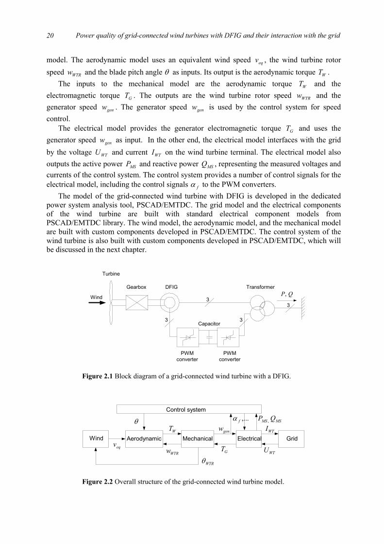
Power quality of grid-connected wind turbines with DFIG and their interaction with the grid
20
model. The aerodynamic model uses an equivalent wind speed eqv , the wind turbine rotor speed WTRw and the blade pitch angle θ as inputs. Its output is the aerodynamic torque WT .
The inputs to the mechanical model are the aerodynamic torque WT and the electromagnetic torque GT . The outputs are the wind turbine rotor speed WTRw and the generator speed genw . The generator speed genw is used by the control system for speed control.
The electrical model provides the generator electromagnetic torque GT and uses the generator speed genw as input. In the other end, the electrical model interfaces with the grid by the voltage WTU and current WTI on the wind turbine terminal. The electrical model also outputs the active power MSP and reactive power MSQ , representing the measured voltages and currents of the control system. The control system provides a number of control signals for the electrical model, including the control signals fα to the PWM converters.
The model of the grid-connected wind turbine with DFIG is developed in the dedicated power system analysis tool, PSCAD/EMTDC. The grid model and the electrical components of the wind turbine are built with standard electrical component models from PSCAD/EMTDC library. The wind model, the aerodynamic model, and the mechanical model are built with custom components developed in PSCAD/EMTDC. The control system of the wind turbine is also built with custom components developed in PSCAD/EMTDC, which will be discussed in the next chapter.
Wind
Turbine
DFIG Transformer
PWMconverter
PWMconverter
Capacitor
Gearbox
3
3 3
3
QP,
Figure 2.1 Block diagram of a grid-connected wind turbine with a DFIG.
Wind GridElectricalMechanicalAerodynamiceqv
WTRw
WT
WTRθGT
genw
WTU
WTIθ
Control system
MSMS QP ,,...fα
Figure 2.2 Overall structure of the grid-connected wind turbine model.
Chapter 2. Model of grid-connected wind turbines with DFIG
21
2.2 Wind model Wind simulation plays an important task in wind turbine modelling, particularly for power
quality analysis of wind farm and their interaction with the grid to which they are connected. The wind models describe the fluctuations in the wind speed, which cause the fluctuations in the power production of the wind turbines.
A wind model has been developed to support studies of the dynamic interaction between large wind farms and the grid to which they are connected, and to support improvement of the electric design of wind turbines as well as grid connection [1, 2, 3]. The wind model is based on a power spectral description of the turbulence, which includes the (park scale) coherence between wind speeds at different wind turbines in a wind farm, together with the effect of rotational sampling of the wind turbine blades in the rotors of the individual wind turbines. Both the spatial variations of the turbulence and the shadows behind the wind turbine towers are included in the model for rotational sampling. The model is verified using measured wind speeds and power fluctuations from wind turbines.
The park scale coherence is included, because it ensures realistic fluctuations in the sum of the power from all wind turbines, which is important for estimating the maximum power and power standard deviation of the wind farm.
The effect of the rotational sampling is included because it is a very important source to the fast power fluctuations during continuous operation of the wind turbine. The fast fluctuations are particularly important to assess the influence of the wind turbines on the flicker levels in the power system.
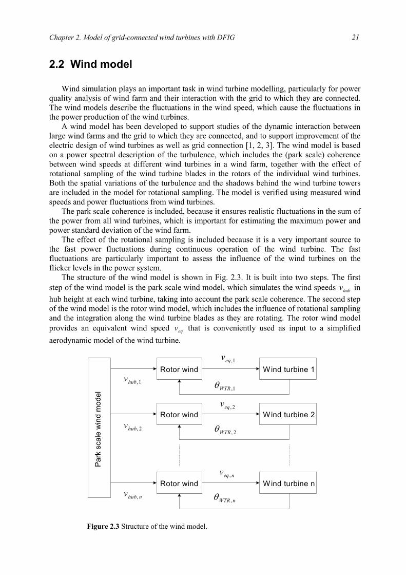
The structure of the wind model is shown in Fig. 2.3. It is built into two steps. The first step of the wind model is the park scale wind model, which simulates the wind speeds hubv in hub height at each wind turbine, taking into account the park scale coherence. The second step of the wind model is the rotor wind model, which includes the influence of rotational sampling and the integration along the wind turbine blades as they are rotating. The rotor wind model provides an equivalent wind speed eqv that is conveniently used as input to a simplified aerodynamic model of the wind turbine.
Park
sca
le w
ind
mod
el
Rotor wind Wind turbine 1
Rotor wind Wind turbine 2
Rotor wind Wind turbine n
1,hubv
nhubv ,
2,hubv
1,eqv
neqv ,
2,eqv
1,WTRθ
nWTR ,θ
2,WTRθ
Figure 2.3 Structure of the wind model.
Power quality of grid-connected wind turbines with DFIG and their interaction with the grid
22
2.2.1 Park scale wind model
The park scale wind model is assumed to be independent of the operation of the wind farm. The park wind model does not include the effects of wakes in the wind farm, but the mean wind speed and turbulence intensity could be modified to account for these effects.
A new method for simulation of park scale wind speeds, the complex cross spectral method, is applied, which directly generates a single time series at the position of each wind turbine. One of the advantages of the new method is that it does not produce more data than what is needed. Due to the data reduction, the new method also reduces the computation time considerably.
2.2.2 Rotor wind model The rotor wind model describes the influence of rotational sampling and integration along
the wind turbine blades as the blades rotate. The model for the wind field includes turbulence as well as tower shadow effects. The effects of wind shear and yaw error are not included in the model, because they only have a small influence on the power fluctuations [1].
The wind speed model provides an equivalent wind speed for each wind turbine, which can be used together with a simple, PC -based aerodynamic model, and still include the effect of rotational sampling of the blades over the rotor disk. The equivalent wind speed is essentially a weighted average of the wind speed along the blades. The weighting ensures that the equivalent wind speed applied to a simple aerodynamic function will result in the same aerodynamic torque on the main shaft as the real wind speed distributed along the blades.
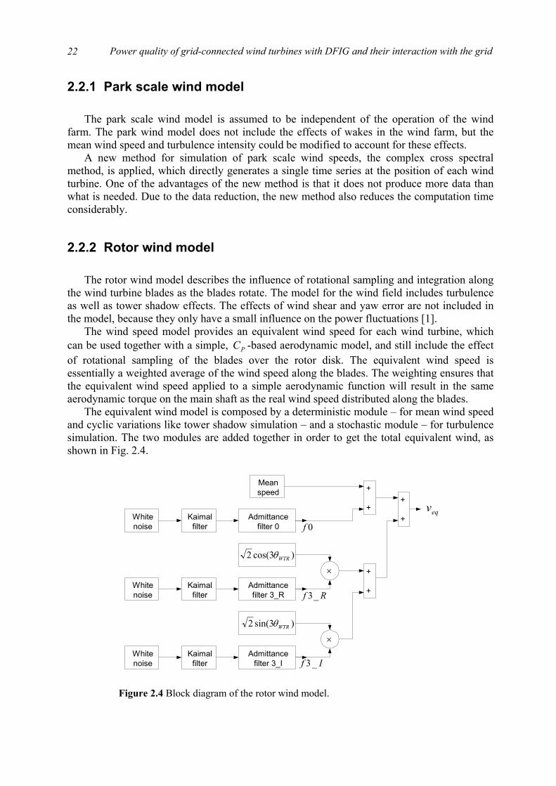
The equivalent wind model is composed by a deterministic module – for mean wind speed and cyclic variations like tower shadow simulation – and a stochastic module – for turbulence simulation. The two modules are added together in order to get the total equivalent wind, as shown in Fig. 2.4.
Whitenoise
Kaimalfilter
Admittancefilter 0
Whitenoise
Kaimalfilter
Admittancefilter 3_R
Whitenoise
Kaimalfilter
Admittancefilter 3_I
Meanspeed
)3cos(2 WTRθ
)3sin(2 WTRθ
+
+
+
++
+eqv
0f
Rf _3
If _3
×
×
Figure 2.4 Block diagram of the rotor wind model.
Chapter 2. Model of grid-connected wind turbines with DFIG
23
The mean speed is included as a part of the deterministic module. The turbines rotor position WTRθ is fed back from the mechanical model. Three times WTRθ accounts for the interference from the 3rd harmonic from tubular towers in upwind turbines.
The white noise represents the source of the turbulence. In the turbulence model, only three components, 0th harmonic component and real and imaginary part of 3rd harmonic component, are included.
The Kaimal filter is to convert a white noise signal to a signal with a normalised Kaimal spectrum. The Kaimal spectrum has been selected as it is commonly used to represent the turbulence for wind turbine design. The parameters in the Kaimal filter can be modified to account for the different wind speed, turbulence intensities and turbulence length scales.
The admittance filters take into account the structure of the turbulence in terms of the coherence between two points in the rotor plane. The parameters in the admittance filters can be modified to account for different wind speeds and rotor disk radiuses.
Today most wind turbines are constructed with a rotor upwind of the tower to reduce the tower interference of the wind flow. Early wind turbines often had lattice tower, but because of the visual impact, tubular towers are the most common today. The tubular towers have more effect on the flow than lattice tower. Neglecting the effect of the blade bending, the tower shadow effects can be added to contributions from the turbulence.
2.3 Aerodynamic model Wind turbine power production depends on the interaction between the wind and the
turbine rotor. The blades of a wind turbine rotor extract some of the energy flow from air in motion, convert it into rotational energy, and then deliver it via a mechanical drive unit to the generator.
2.3.1 Power extraction from the air stream
Within its region of action, the rotor absorbs energy from the air stream, and can therefore
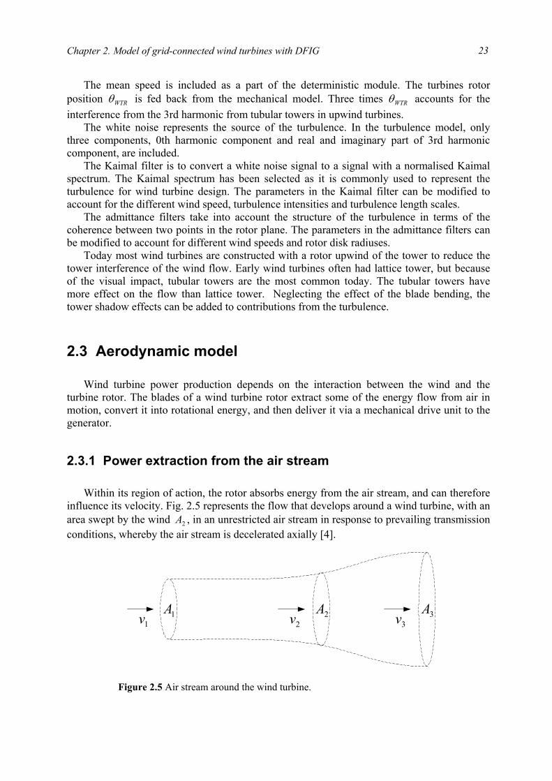
influence its velocity. Fig. 2.5 represents the flow that develops around a wind turbine, with an area swept by the wind 2A , in an unrestricted air stream in response to prevailing transmission conditions, whereby the air stream is decelerated axially [4].
1A 3A2A1v 2v 3v
Figure 2.5 Air stream around the wind turbine.

Power quality of grid-connected wind turbines with DFIG and their interaction with the grid
24
The energy absorbed from an air volume aV of cross-section 1A and swirl-free speed of flow 1v far upstream of the turbine, which results in a downstream reduction of flow speed to
3v with a corresponding broadening of the cross-section area to 3A , can be expressed as
)(2
23
21 vvVW aW −=
ρ (2.1)
where ρ is the air density [kg/m3]. The wind turbine power WP may therefore be expressed as
dt
vvVd
dtdW
Pa
WW
−
==)(
223
21
ρ
(2.2)
An air volume flow in the rotor area ( AA =2 ) of
2Avdt
dVa = (2.3)
yields, in quasi-steady state,
223
21 )(
2vvvAPW −=
ρ (2.4)
The maximum wind turbine power output 31max, 227
16 AvPWρ
⋅= (2.5)
is obtained when
13
12
3132
vv
vv
=
= (2.6)
The ratio of the power WP absorbed by the turbine to that of the wind 310 2
AvP ρ= (2.7)
under smooth air flow conditions at the turbine defines the power coefficient pC
0PPC W
p = (2.8)
which has the maximum value
5926.02716
max, ==pC (2.9)
2.3.2 Aerodynamic model The wind turbine rotor that extracts the energy from the wind and converts it into
mechanical power is a complex aerodynamic system. For state of the art modelling of the rotor, blade element theory must be used [4]. Modelling the rotor using blade element theory has, however, a number of drawbacks:
• instead of only one wind speed signal, an array of wind speed signals has to be applied.
Chapter 2. Model of grid-connected wind turbines with DFIG
25
• detailed information about the rotor geometry should be available.
• computations become complicated and lengthy.
To solve these problems, a simplified way of modelling the aerodynamic behaviour of the wind turbine rotor is normally used when the electrical behaviour of the wind turbine is the main interest of the study. The relation between the wind speed and aerodynamic power may be described by the following equation:
),(21 32 λθρπ peqW CvRP = (2.10)
The corresponding aerodynamic torque can be expressed as
λλθρπ /),(21 23
peqW CvRT = (2.11)
where WP is the aerodynamic power extracted from the wind [W], WT is the aerodynamic torque extracted from the wind [Nm], ρ is the air density [kg/m3], R is the wind turbine rotor radius [m], eqv is the equivalent wind speed [m/s], θ is the pitch angle of rotor [deg],
eqWTR vRw /=λ is the tip speed ratio, where WTRw is the wind turbine rotor speed [rad/s], pC is the power coefficient.
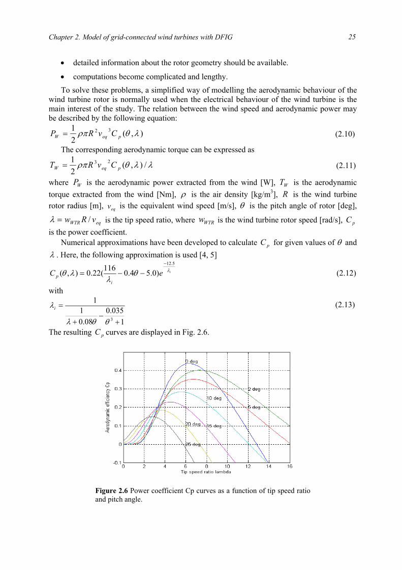
Numerical approximations have been developed to calculate pC for given values of θ and λ . Here, the following approximation is used [4, 5]
ieCi
pλθ
λλθ
5.12
)0.54.0116(22.0),(−
−−= (2.12)
with
1035.0
08.01
1
3 +−
+
=
θθλ
λi (2.13)
The resulting pC curves are displayed in Fig. 2.6.
Figure 2.6 Power coefficient Cp curves as a function of tip speed ratioand pitch angle.

Power quality of grid-connected wind turbines with DFIG and their interaction with the grid
26
2.3.3 Aerodynamic power control At high wind speeds it is necessary to limit the input power to the turbine, i.e. aerodynamic
power control. There are three major methods of aerodynamic power control: stall, pitch and active stall control [6]. The three methods are described in detail as follows:
• Stall control implies that the blades are designed to stall in high wind speeds and no pitch mechanism is thus required.
• Pitch control is the most common method of controlling the aerodynamic power generated by a turbine rotor for newer larger wind turbines. Almost all variable speed wind turbines use pitch control. Below rated wind speed the turbine should produce as much power as possible, i.e. using a pitch angle that maximizes the energy capture. Above rated wind speed the pitch angle is controlled in such a way that the aerodynamic power is kept at its rated value. In order to limit the aerodynamic power, at high wind speeds, the pitch angle is controlled to decrease the angle of attack.
• It is also possible to increase angle of attack towards stall in order to limit the aerodynamic power. This method can be used to fine-tune the power level at high wind speeds for fixed speed turbines. This control method is known as active stall.
2.4 Mechanical model In the mechanical model, emphasis is put only on the parts of the dynamic structure of the
wind turbine that contribute to the interaction with the grid, i.e. which influences significantly on the output power of the wind turbine. Therefore, only the drive train is considered because this part of the wind turbine has the most significant impact on the output power, while the other parts of the wind turbine structure, e.g. tower and flap bending modes, are neglected.
Neglecting the dynamics of the mechanical parts, the drive train may be modelled with a single lumped mass. Since there exists a gearbox, the quantities on the high-speed side have been referred to the low speed side. The lumped model of the mechanical drive train thus can be expressed as [7]:
WTRGWWTR
WG DwTTdt
dwJ −−= ' (2.14)
where WGJ is the wind turbine mechanical inertia plus generator mechanical inertia [kg·m2],
WTRw is the wind turbine rotor speed [rad/s], WT is the wind turbine input aerodynamic torque [Nm], 'GT is the generator electromagnetic torque referred to the low speed side [Nm], and D is friction coefficient [Nm/rad].
The flicker level is usually quantified by the short-term flicker severity, which is normally measured over a ten-minute period [8]. Since the measurement lasts so long a time, the dynamics of the mechanical parts may be neglected. Therefore, the lumped mechanical model can be used for flicker study of grid-connected wind turbines.
The modelling of the wind turbine mechanical drive train has impact on the transient analysis of the wind turbine in an external short-circuit fault situation [9, 10, 11]. In [9, 10], the effect of the way the mechanical drive train of the wind power generation system is
Chapter 2. Model of grid-connected wind turbines with DFIG
27
modelled in terms whether using the lumped model or a shaft model has been investigated. The wind power generation system using the shaft model is liable to lose stability after an external short-circuit fault, in comparison with the one using the lumped model. Due to the shaft model, the transient response of the wind power generation system is subjected to relatively high oscillations while that of the wind power generation system using the lumped model almost contains no oscillation.
In this research work, the aim of the voltage recovery study of the grid-connected wind turbines is not focused on in which post-fault situation the wind turbines will lose stability, but on proposing effective measures or control strategies for wind turbine voltage recovery in unstable situations. Thus, the voltage recovery study may be carried out on a wind turbine using the lumped mechanical model, and the proposed measures or control strategies may be extended to wind turbines using more detailed mechanical drive train models.
2.5 DFIG model The DFIG is a wound rotor induction generator, where the rotor circuit is connected to the
grid through power electronic devices. The ability to supply/subtract power to/from the rotor makes it possible to operate the DFIG at sub- or super-synchronous speed, while keeping constant voltage and frequency on the stator terminals. Therefore, the DFIG is often used where variable speed, constant frequency generation is required.
PSCAD/EMTDC software library provides a dedicated model of the wound rotor induction generator with rotor voltages interference, which is applied in this study. The wound rotor induction generator is modelled in the state variable form using generalized machine theory. The stator and the rotor windings are transformed to their two-phase equivalent using the dq0-transformation. The wound rotor induction generator model is built with detailed descriptions of the stator and rotor direct and quadrature axis currents (or flux linkages) and the rotor speed.
To have a good understanding of the DFIG, the following sections describe the steady state equivalent circuit and the operation principle as well as the dq-models both in the arbitrary and rotor fixed reference frame.
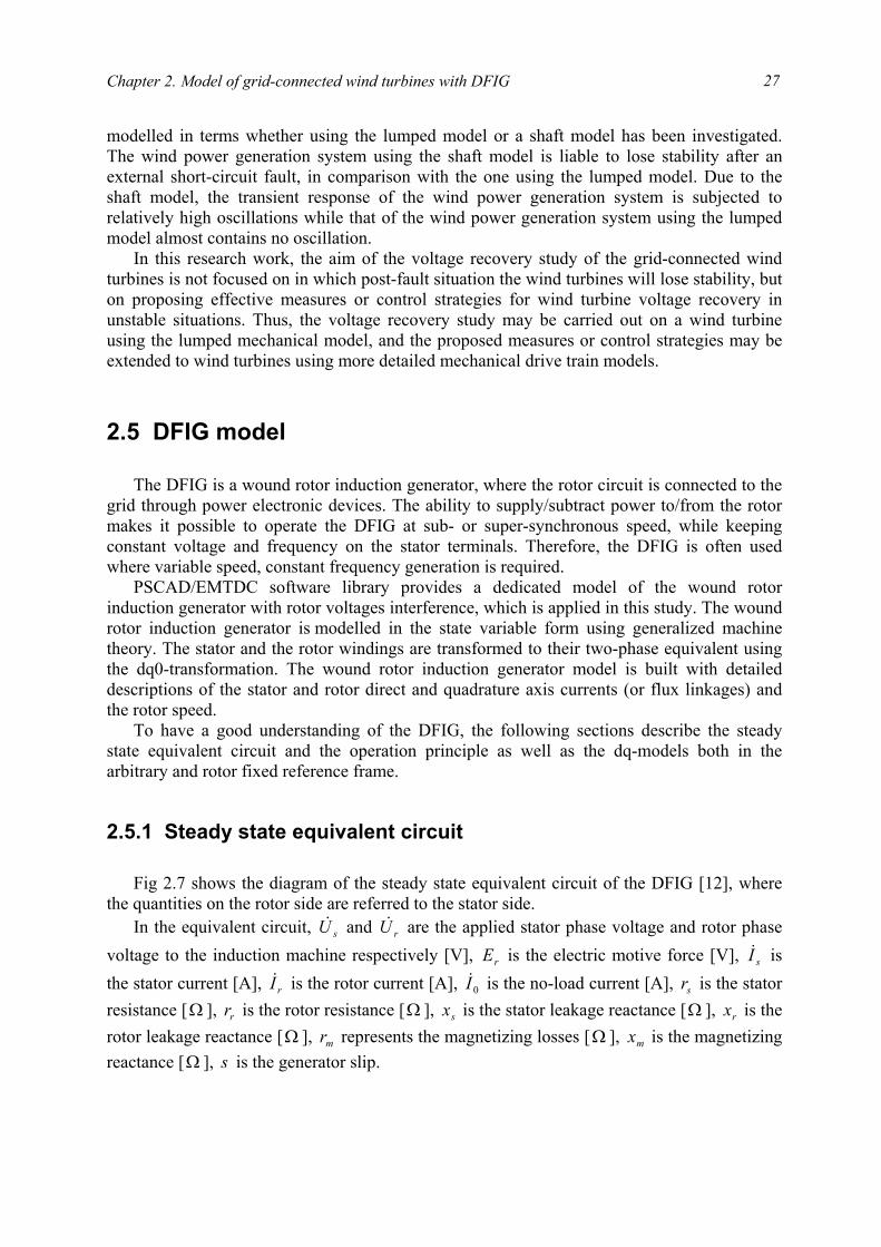
2.5.1 Steady state equivalent circuit Fig 2.7 shows the diagram of the steady state equivalent circuit of the DFIG [12], where
the quantities on the rotor side are referred to the stator side. In the equivalent circuit, sU& and rU& are the applied stator phase voltage and rotor phase
voltage to the induction machine respectively [V], rE is the electric motive force [V], sI& is the stator current [A], rI& is the rotor current [A], 0I& is the no-load current [A], sr is the stator resistance [ Ω ], rr is the rotor resistance [ Ω ], sx is the stator leakage reactance [Ω ], rx is the rotor leakage reactance [ Ω ], mr represents the magnetizing losses [ Ω ], mx is the magnetizing reactance [ Ω ], s is the generator slip.

Power quality of grid-connected wind turbines with DFIG and their interaction with the grid
28
Applying Kirchhoff’s voltage law to the circuit in Fig. 2.7 yields
rs
mmr
rrrrrr
rsssss
III
IjxrE
EIjxIsr
sU
EIjxIrU
&&&
&&
&&&&
&&&&
+=
⋅+−=
−+=
−+=
0
0)( (2.15)
This equivalent circuit, based on calculations with rms-values of voltages and currents, can only be applied for steady state analysis of the DFIG. For dynamic analysis of the DFIG, a model in form of differential functions has to be employed, which will be introduced in the following sections.
2.5.2 Operation principle
For an ordinary wound rotor induction generator with short-circuited rotor, i.e. the applied
voltage to the rotor rU& is zero, the relationship between the electromagnetic torque and the real current in the rotor circuit can be expressed as [13]
ramT ICT Φ= (2.16) where T is the electromagnetic torque [Nm], TC is the torque coefficient, mΦ is the air gap magnetic flux per phase [Wb], raI is the real current in the rotor circuit [A].
The real current in the rotor circuit can be calculated with the following equation:
22
2222
)(
)()(
rr
rr
rr
r
rr
rra
sxrEsr
sxr
r
sxr
sEI
+=
++=
(2.17)
where s is the generator slip. According to (2.16), as the voltage applied to the stator of the induction generator and the
load torque are kept constant, the real current in the rotor circuit will be a constant value. Neglecting the rotor reactance yields
sr srr
mr
sU&s
U r&
sjx rjx
mjxrE&
sI& rI&
0I&
Figure 2.7 Steady state equivalent circuit of the DFIG.
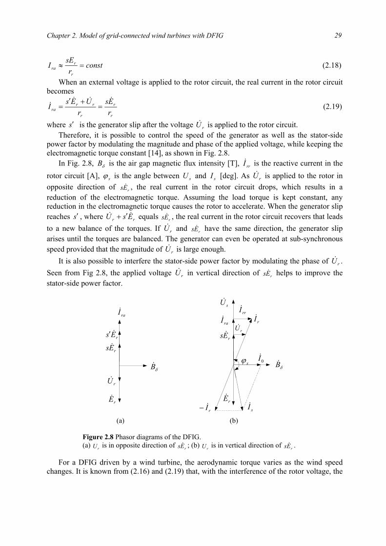
Chapter 2. Model of grid-connected wind turbines with DFIG
29
constr
sEIr
rra =≈ (2.18)
When an external voltage is applied to the rotor circuit, the real current in the rotor circuit becomes
r
r
r
rrra r
Esr
UEsI&&&
& =+′
= (2.19)
where s′ is the generator slip after the voltage rU& is applied to the rotor circuit. Therefore, it is possible to control the speed of the generator as well as the stator-side
power factor by modulating the magnitude and phase of the applied voltage, while keeping the electromagnetic torque constant [14], as shown in Fig. 2.8.
In Fig. 2.8, δB is the air gap magnetic flux intensity [T], rrI& is the reactive current in the rotor circuit [A], sϕ is the angle between sU and sI [deg]. As rU& is applied to the rotor in opposite direction of rEs & , the real current in the rotor circuit drops, which results in a reduction of the electromagnetic torque. Assuming the load torque is kept constant, any reduction in the electromagnetic torque causes the rotor to accelerate. When the generator slip reaches s′ , where rr EsU && ′+ equals rEs & , the real current in the rotor circuit recovers that leads to a new balance of the torques. If rU& and rEs & have the same direction, the generator slip arises until the torques are balanced. The generator can even be operated at sub-synchronous speed provided that the magnitude of rU& is large enough.
It is also possible to interfere the stator-side power factor by modulating the phase of rU& . Seen from Fig 2.8, the applied voltage rU& in vertical direction of rEs & helps to improve the stator-side power factor.
For a DFIG driven by a wind turbine, the aerodynamic torque varies as the wind speed
changes. It is known from (2.16) and (2.19) that, with the interference of the rotor voltage, the
δB&
rU&
rEs &
raI&
rEs &′
δB&
rU&
rEs &raI&
sU&
0I&
rrI&
rI&
rI&− sI&rE& rE&
sϕ
(a) (b) Figure 2.8 Phasor diagrams of the DFIG. (a) rU is in opposite direction of rEs & ; (b) rU is in vertical direction of rEs & .

Power quality of grid-connected wind turbines with DFIG and their interaction with the grid
30
electromagnetic torque may be varied so that the generator operates at the required speeds. Meanwhile, regulating the rotor voltage may control the stator-side power factor.
With the interference of the voltage in the rotor circuit, the DFIG can be operated in both sub-synchronous and super-synchronous mode. The corresponding phasor diagrams are shown in Fig. 2.9, where rϕ is the angle between rU and rI [deg].
The rotor subtracts power from the grid when the generator is operated in sub-synchronous mode. On the contrary, in super-synchronous mode, the rotor supplies power to the grid.
2.5.3 Dq-model in the arbitrary reference frame
For control of dynamic sequences, the standard equivalent circuit shown in Fig. 2.7 is
inadequate, as the model is based on calculations with rms-values of voltages and currents. A dynamic model is set up in the form of the two-phase dq-representation. Thereby, the complexity of the three-phase differential equations, where some of the machine inductances are functions of the rotor speed and the voltage equations are time varying, is avoided.
The reduction from three- to two-phase reference frame has the advantage that the fluxes in the two phases or directions do not interact with each other. This gains the advantage that time varying variables of the three-phase system becomes constant when referred to the two-phase system. Those advantages are independent of the choice of reference frame.
The following assumptions are set up for developing the dq-model [14]:
• The stator and rotor windings of the DFIG are assumed symmetric, i.e. resistance, magnetizing and leakage inductances are equal for all three phases. This means the zero-component of the dq-model may be eliminated.
rI&rEs &′
rEs &
rU&
0I&
sI&
sϕ
rϕ
rI&
rI&−rEs &′
rEs &
rU&
rE&−sU&
0I&
sI&
sϕ
rϕ
sU&
rE&−
rI&−
(a) (b) Figure 2.9 Phasor diagrams of the DFIG in different operation modes. (a) sub-synchronous mode; (b) super-synchronous mode.

Chapter 2. Model of grid-connected wind turbines with DFIG
31
• The windings are assumed sinusoidal distributed around the circumference of the DFIG. Thereby, the magnetic motive force produced by the windings will be sinusoidal i.e. no harmonic components will be present.
• The air gap is assumed constant, meaning constant air gap reluctance. In consequence the mutual inductances from stator to stator windings and from rotor to rotor windings are constant. Only the mutual inductance from stator to rotor winding varies.
• Saturation of the mutual inductance, or magnetizing inductance, is neglected i.e. the magnetizing inductance does not vary as a function of the current.
• Skin effect in the stator and rotor is neglected. As the frequency of the current increases, skin effect will increase the resistance, and decrease the inductance due to increased reluctance in the iron of the DFIG.
• Iron losses are neglected. This means that the real losses in DFIG will be larger than simulated.
• Cross saturation effect, the coupling between two perpendicular axes, is neglected.
Essentially, the dq-model is a simple reduction from a three-phase representation to a two-phase representation. The three axes, which represent the three-phase abc in the standard model, are projected on two axes, respectively the d- and q-axis. The transformation matrix is expressed as [13]
[ ]
°+−°−−−
°+°−=
)120sin()120sin(sin)120cos()120cos(cos
32
θθθθθθ
P (2.20)
where θ is the angle between the abc- and dq- axis. The corresponding diagram for the abc-to-dq transformation is shown in Fig. 2.10, where genw is the generator rotor speed.
The model in the two-phase system in the arbitrary reference frame is as follows [15, 16], where the quantities on the rotor side are referred to the stator side.
a
d
cb
q
θgenw
Figure 2.10 Vector diagram of the abc-to-dq transformation.

Power quality of grid-connected wind turbines with DFIG and their interaction with the grid
32
dsqs
qssqs
qsds
dssds
wdt
diru
wdt
diru
ψψ
ψψ
++=
−+= (2.21)
drrqr
qrrqr
qrrdr
drrdr
wwdt
diru
wwdt
diru
ψψ
ψψ
)(
)(
−++=
−−+= (2.22)
qrmqssqs
drmdssds
iLiLiLiL
+=+=
ψψ
(2.23)
qsmqrrqr
dsmdrrdr
iLiLiLiL
+=+=
ψψ
(2.24)
where
mlrr
mlss
LLLLLL
+=+=
(2.25)
where qrdrqsds uuuu ,,, , qrdrqsds iiii ,,, and qrdrqsds ψψψψ ,,, are voltages [V], currents [A] and flux linkages [Wb] of the stator and rotor in d- and q-axis, sr and rr are the resistances of the stator and rotor windings [ Ω ], mrs LLL ,, are the stator, rotor and mutual inductances [H],
lrls LL , are the stator and rotor leakage inductances [H], w is the speed of the reference frame [rad/s], rw is the electrical angular velocity of the generator rotor [rad/s].
By calculating the apparent power and taking the real parts the following equations represent the stator-side and rotor-side active power respectively.
)(23
)(23
qrqrdrdrr
qsqsdsdss
iuiuP
iuiuP
+=
+= (2.26)
The rotor-side active power can also be found from the following equation sr sPP −= (2.27)
Accordingly the imaginary parts of the apparent power represent the stator-side and rotor-side reactive power respectively.
)(23
)(23
qrdrdrqrr
qsdsdsqss
iuiuQ
iuiuQ
−=
−= (2.28)
The mutual flux between rotor and stator produces magnetic energy, which is stored in the magnetic field. This energy produces an electromagnetic torque which is calculated as
)(23
qrdsdrqsmG iiiipLT −= (2.29)
where p is the number of pole pairs. An equivalent circuit may be set up by means of the voltage and flux linkage equations of
the arbitrary reference frame, as shown in Fig 2.11.
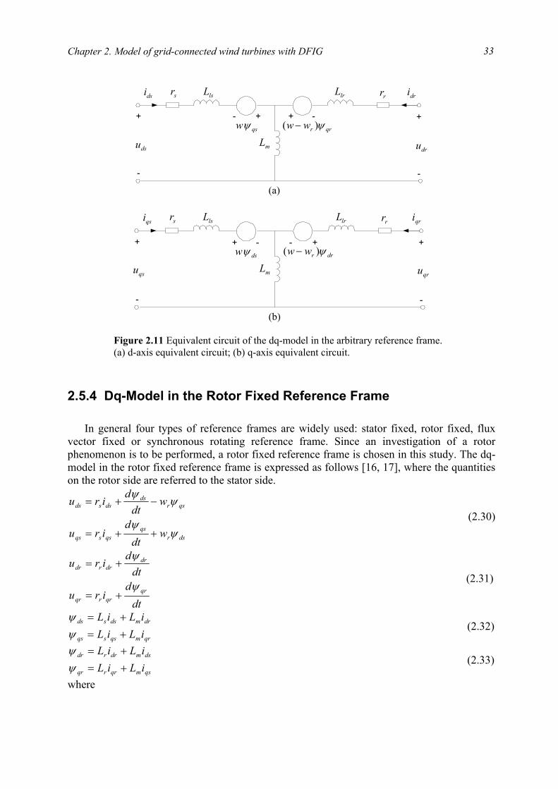
Chapter 2. Model of grid-connected wind turbines with DFIG
33
2.5.4 Dq-Model in the Rotor Fixed Reference Frame
In general four types of reference frames are widely used: stator fixed, rotor fixed, flux
vector fixed or synchronous rotating reference frame. Since an investigation of a rotor phenomenon is to be performed, a rotor fixed reference frame is chosen in this study. The dq-model in the rotor fixed reference frame is expressed as follows [16, 17], where the quantities on the rotor side are referred to the stator side.
dsrqs
qssqs
qsrds
dssds
wdt
diru
wdt
diru
ψψ
ψψ
++=
−+= (2.30)
dtd
iru
dtd
iru
qrqrrqr
drdrrdr
ψ
ψ
+=
+= (2.31)
qrmqssqs
drmdssds
iLiLiLiL
+=+=
ψψ
(2.32)
qsmqrrqr
dsmdrrdr
iLiLiLiL
+=+=
ψψ
(2.33)
where
sr
mLdsu
qswψ
rrdsi
+
-
dru
+
-
lsL lrL
+- + -
dri
qrrww ψ)( −
(a)
sr
mLqsu
dswψ
rrqsi
+
-
qru
+
-
lsL lrL
+ - +-
qri
drrww ψ)( −
(b) Figure 2.11 Equivalent circuit of the dq-model in the arbitrary reference frame. (a) d-axis equivalent circuit; (b) q-axis equivalent circuit.
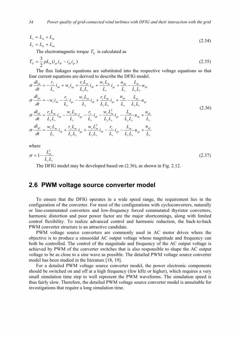
Power quality of grid-connected wind turbines with DFIG and their interaction with the grid
34
mlrr
mlss
LLLLLL
+=+=
(2.34)
The electromagnetic torque GT is calculated as
)(23
qrdsdrqsmG iiiipLT −= (2.35)
The flux linkages equations are substituted into the respective voltage equations so that four current equations are derived to describe the DFIG model.
r
qrqs
rs
mqr
r
rdr
rs
mrqs
rs
msds
r
mrqr
r
drds
rs
mqr
rs
mrdr
r
rqs
r
mrds
rs
msdr
qrrs
m
s
qsqr
rs
mrdr
s
mrqs
s
sdsr
qs
drrs
m
s
dsqr
s
mrdr
rs
mrqsrds
s
sds
Lu
uLL
Li
Lr
iLLLw
iLLLr
iLLw
dtdi
Lu
uLL
Li
LLLw
iLri
LLw
iLLLr
dtdi
uLL
LLu
iLLLr
iLLw
iLr
iwdt
di
uLL
LLu
iLLw
iLLLr
iwiLr
dtdi
+−−++=
+−−−−=
−++−−−=
−++++−=
2
2
σ
σ
σ
σ
(2.36)
where
rs
m
LLL2
1−=σ (2.37)
The DFIG model may be developed based on (2.36), as shown in Fig. 2.12.
2.6 PWM voltage source converter model To ensure that the DFIG operates in a wide speed range, the requirement lies in the
configuration of the converter. For most of the configurations with cycloconverters, naturally or line-commutated converters and low-frequency forced commutated thyristor converters, harmonic distortion and poor power factor are the major shortcomings, along with limited control flexibility. To realize advanced control and harmonic reduction, the back-to-back PWM converter structure is an attractive candidate.
PWM voltage source converters are commonly used in AC motor drives where the objective is to produce a sinusoidal AC output voltage whose magnitude and frequency can both be controlled. The control of the magnitude and frequency of the AC output voltage is achieved by PWM of the converter switches that is also responsible to shape the AC output voltage to be as close to a sine wave as possible. The detailed PWM voltage source converter model has been studied in the literature [18, 19].
For a detailed PWM voltage source converter model, the power electronic components should be switched on and off at a high frequency (few kHz or higher), which requires a very small simulation time step to well represent the PWM waveforms. The simulation speed is thus fairly slow. Therefore, the detailed PWM voltage source converter model is unsuitable for investigations that require a long simulation time.
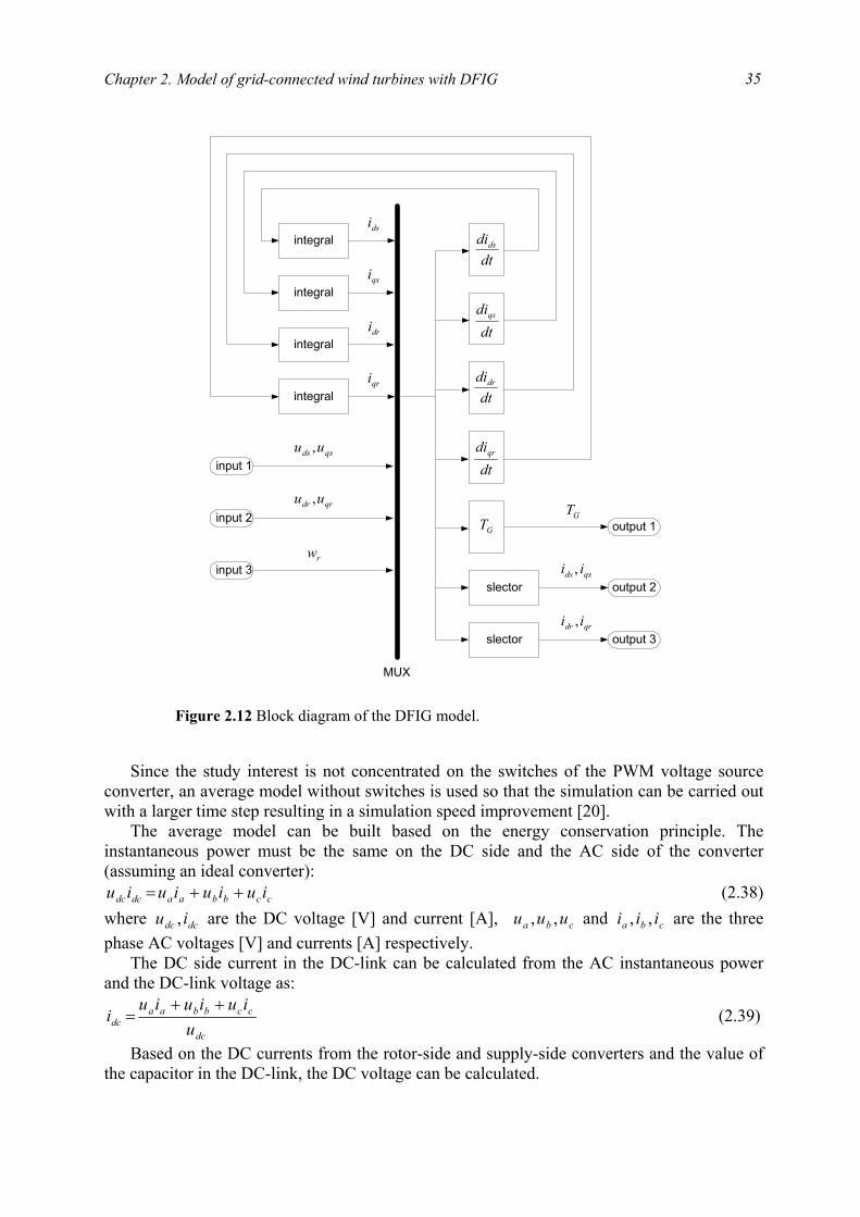
Chapter 2. Model of grid-connected wind turbines with DFIG
35
Since the study interest is not concentrated on the switches of the PWM voltage source
converter, an average model without switches is used so that the simulation can be carried out with a larger time step resulting in a simulation speed improvement [20].
The average model can be built based on the energy conservation principle. The instantaneous power must be the same on the DC side and the AC side of the converter (assuming an ideal converter):
ccbbaadcdc iuiuiuiu ++= (2.38) where dcdc iu , are the DC voltage [V] and current [A], cba uuu ,, and cba iii ,, are the three phase AC voltages [V] and currents [A] respectively.
The DC side current in the DC-link can be calculated from the AC instantaneous power and the DC-link voltage as:
dc
ccbbaadc u
iuiuiui
++= (2.39)
Based on the DC currents from the rotor-side and supply-side converters and the value of the capacitor in the DC-link, the DC voltage can be calculated.
dtdids
dtdidr
dtdiqs
dtdiqr
integral
integral
integral
integral
dsi
dri
qsi
qri
input 1
input 2
input 3
qsds uu ,
qrdr uu ,
rw
GT
slector
slector
output 1
output 2
output 3
qsds ii ,
qrdr ii ,
GT
MUX
Figure 2.12 Block diagram of the DFIG model.
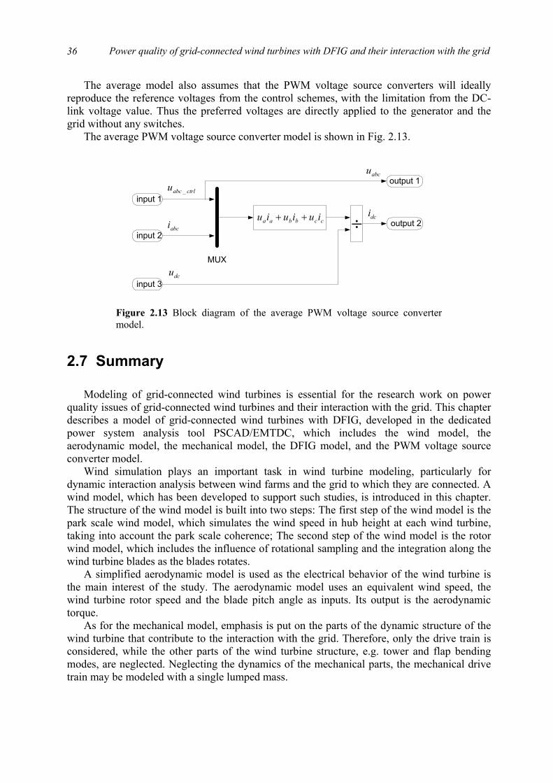
Power quality of grid-connected wind turbines with DFIG and their interaction with the grid
36
The average model also assumes that the PWM voltage source converters will ideally reproduce the reference voltages from the control schemes, with the limitation from the DC-link voltage value. Thus the preferred voltages are directly applied to the generator and the grid without any switches.
The average PWM voltage source converter model is shown in Fig. 2.13.
2.7 Summary
Modeling of grid-connected wind turbines is essential for the research work on power
quality issues of grid-connected wind turbines and their interaction with the grid. This chapter describes a model of grid-connected wind turbines with DFIG, developed in the dedicated power system analysis tool PSCAD/EMTDC, which includes the wind model, the aerodynamic model, the mechanical model, the DFIG model, and the PWM voltage source converter model.
Wind simulation plays an important task in wind turbine modeling, particularly for dynamic interaction analysis between wind farms and the grid to which they are connected. A wind model, which has been developed to support such studies, is introduced in this chapter. The structure of the wind model is built into two steps: The first step of the wind model is the park scale wind model, which simulates the wind speed in hub height at each wind turbine, taking into account the park scale coherence; The second step of the wind model is the rotor wind model, which includes the influence of rotational sampling and the integration along the wind turbine blades as the blades rotates.
A simplified aerodynamic model is used as the electrical behavior of the wind turbine is the main interest of the study. The aerodynamic model uses an equivalent wind speed, the wind turbine rotor speed and the blade pitch angle as inputs. Its output is the aerodynamic torque.
As for the mechanical model, emphasis is put on the parts of the dynamic structure of the wind turbine that contribute to the interaction with the grid. Therefore, only the drive train is considered, while the other parts of the wind turbine structure, e.g. tower and flap bending modes, are neglected. Neglecting the dynamics of the mechanical parts, the mechanical drive train may be modeled with a single lumped mass.
input 1ctrlabcu _
input 2
input 3dcu
abci ccbbaa iuiuiu ++
MUX
÷
output 1
output 2dci
abcu
Figure 2.13 Block diagram of the average PWM voltage source convertermodel.

Chapter 2. Model of grid-connected wind turbines with DFIG
37
The DFIG is a wound rotor induction generator, where the rotor circuit is connected to the grid through power electronic devices. PSCAD/EMTDC software library provides a dedicated model of the wound rotor induction generator with rotor voltages interference. The wound rotor induction generator model is built with detailed description of the stator and rotor direct and quadrature axis currents (or flux linkages) and the rotor speed.
For a detailed PWM voltage source converter model, the power electronic components should be switched on and off at a very high frequency (several kHz or higher), which requires a very small simulation time step to well represent the PWM waveforms. Since the study interest is not concentrated on the switches of the PWM voltage source converter, an average model without switches is used so that the simulation can be carried out with a larger time step resulting in a simulation speed improvement. The average model is built based on the energy conservation principle.
Bibliography
[1] P. Sørensen, A. Hansen, L. Janosi, J. Bech, B. Bak-Jensen, Simulation of interaction between wind farm and power system, Risø-R-1281(EN), Risø National Laboratory, Dec. 2001.
[2] P. Sørensen, A. D. Hansen, P. A. C. Rosas, “Wind models for simulation of power fluctuations from wind farms,” Journal of Wind Engineering and Industrial Aerodynamics, vol. 90, pp. 1381-1402, Dec. 2002.
[3] P. A. C. Rosas, P. Sørensen, H. Bindner, “Fast wind modeling for wind turbines,” Proc. of the Wind Power for the 21 Century: EUWER Special Topic Conference and Exhibition, pp. 184-187, Sept. 2000.
[4] S. Heier, Grid integration of wind energy conversion systems, John Wiley & Sons Ltd, Chichester, 1998.
[5] J. G. Slootweg, H. Polinder, W. L. Kling, “Dynamic modeling of a wind turbine with direct drive synchronous generator and back to back voltage source converter and its control,” Proc. of the European Wind Energy Conference, pp. 1014-1017, July 2001.
[6] T. Burton, D. Sharpe, N. Jenkins, E. Bossanyi, Wind energy handbook, John Wiley & Sons Ltd, Chichester, 2001.
[7] Z. Chen, E. Spooner, “Grid power quality with variable speed wind turbines,” IEEE Trans. on Energy Conversion, vol. 16, no. 2, pp. 148-154, June 2001.
[8] International Electrotechnical Commission, Electromagnetic Compatibility (EMC) --- Part 4: Testing and measurement techniques --- Section 15: Flickermeter --- Functional and design specifications, IEC 61000-4-15, International Electrotechnical Commission, Geneva, Switzerland, Nov. 1997.
[9] S. K. Salman, A. L. J. Teo, “Windmill modeling consideration and factors influencing the stability of a grid-connected wind power-based embedded generator,” IEEE Trans. on Power Systems, vol. 18, no. 2, pp. 793-802, May 2003.

Power quality of grid-connected wind turbines with DFIG and their interaction with the grid
38
[10] S. K. Salman, A. L. J. Teo, “Improvement of fault clearing time of wind farm using reactive power compensation,” Proc. of 2001 IEEE Porto Power Tech Conference, vol. 2, pp. 6/1-6/6, Sept. 2001.
[11] V. Akhmatov, H. Knudsen, “Modelling of windmill induction generators in dynamic simulation programs,” Proc. of International Conference on Electric Power Engineering, pp. 108, Aug./Sept. 1999.
[12] I. Boldea, S.A. Nasar, The induction machine handbook, CRC Press, Boca Raton, 2002.
[13] F. H. Li, D. Q. Zhu, The electric machine, The Science Press, Beijing, third edition, 2002.
[14] J. D. Gao, X. H. Wang, F. H. Li, Analysis of alternative current electric machine system, The Qinghua Press, Beijing, 1993.
[15] Y. K. He, Computer simulation of alternative current electric machinery, The Science Press, Beijing, 1990.
[16] J. Chen, Mathematic model and speed-regulating system of alternative current electric machinery, The National Defense Industry Press, Beijing, 1989.
[17] M. Chomit, J. Bendl, L. Schreier, “Extended vector control of doubly fed machine under unbalanced power network conditions,” Proc. of the International Conference on Power Electronics, Machines and Drives, pp. 329-334, June 2002.
[18] N. Mohan, T. M. Undeland, W.P. Robbins, Power electronics – converters, applications, and design, John Wiley & Sons Inc, USA, third edition, 2003.
[19] A. M. Trzynadlowski, Introduction to modern power electronics, John Wiley & Sons Inc, New York, 1998.
[20] P. Giroux, G. Sybille, H. Le-Huy, “Modeling and simulation of a distribution STATCOM using simulink’s power system blockset,” Proc. of the 27th Annual Conference of the IEEE Industrial Electronics Society, vol. 2, pp. 990-994, Nov./ Dec., 2001.
39
Chapter 3
Control schemes and performance of grid-connected wind turbines with DFIG
An advantage of variable speed wind turbines is that the rotor speed can be adjusted in proportion to the wind speed in low to moderate wind speeds so that the optimal tip speed ratio is maintained. At this tip speed ratio the power coefficient is at maximum, which means that the energy conversion is maximized. For a variable speed wind turbine with a DFIG, it is possible to control the load torque of the generator directly, so that the speed of the turbine rotor can be varied within certain limits. Thus the optimal tip speed ratio as well as the maximal power coefficient can be obtained.
In general, variable speed wind turbines may have two different control goals, depending on the wind speed. In low to moderate wind speeds, the control goal is to maintain a constant optimum tip speed ratio for maximum energy conversion. In high wind speeds, the control goal is to keep the rated output power.
To achieve the two control goals mentioned above, two control schemes are implemented in the grid-connected wind turbine model developed in Chapter 2: speed control and pitch control. The speed control scheme is composed by two vector-control schemes designed respectively for the rotor-side and grid-side PWM voltage source converter. The pitch control scheme is employed to regulate the aerodynamic power from the turbine. Under the control of the schemes, the grid-connected wind turbine with DFIG provides satisfactory performance.
This chapter presents the control schemes and performance of grid-connected wind turbines with DFIG. First, the speed control scheme, i.e. the two vector-control schemes designed respectively for the rotor-side and grid-side PWM voltage source converter, is introduced. Two design methods, pole-placement and internal model control, are applied for designing the PI-controllers in the vector-control schemes. Next, the pitch control scheme, responsible for regulating the aerodynamic power from the turbine, is described. Finally, the performance of the control schemes and the wind turbine are discussed.

Power quality of grid-connected wind turbines with DFIG and their interaction with the grid
40
3.1 Speed control scheme Fig. 3.1 shows the block diagram for the overall control schemes of the DFIG wind
turbine, including the speed control scheme and the pitch control scheme, where ss iv , are the
stator voltages [V] and currents [A], ri are the rotor currents [A], gv are the grid voltages
[V], gi are the grid-side converter currents [A], rw is the electrical angular velocity of the
generator rotor [rad/s], dcu is the DC-link voltage [V], refsrefs QP __ , are the reference values of the stator-side active [W] and reactive power [Var], refrQ _ is the reference value of the
reactive power flow between the grid and the grid-side converter [Var], refdcu _ is the
reference value of the DC-link voltage [V], C is the DC-link capacitor [F], eqv is the equivalent wind speed [m/s], refθ is the reference value of the pitch angle [Deg], θ is the real value of the pitch angle [Deg].
This section is concentrated on description of the speed control scheme. Vector-control
techniques, which have been well developed for DFIG using back-to-back PWM converters [1, 2, 3, 4], are applied in the speed control scheme. The speed control scheme is composed of two vector-control schemes designed respectively for the rotor-side and grid-side PWM voltage source converter, as shown in Fig. 3.1.
The objective of the vector-control scheme for the grid-side PWM voltage source converter is to keep the DC-link voltage constant regardless of the magnitude and direction of the rotor power, as well as keeping sinusoidal grid currents. It may also be responsible for controlling reactive power flow into the grid by adjusting refrQ _ .
PWM PWM
Rotor-sidevectorcontrol
Grid-sidevectorcontrol
gi
gvdcu
risisvrw
refsP _ refsQ _ refdcu _ refrQ _
DFIGGearbox Transformer
Turbine
C
rw)( rs wfP =
Look-up table
Inductor
Look-up table
eqv
refθ
Pitchmechanism
θ
)( eqvf=θ
Figure 3.1 Block diagram for the overall control schemes of the wind turbine with DFIG.
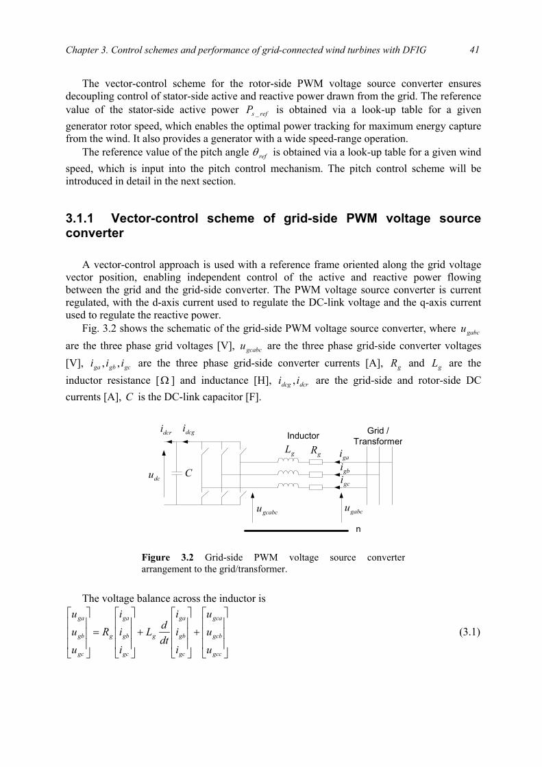
Chapter 3. Control schemes and performance of grid-connected wind turbines with DFIG
41
The vector-control scheme for the rotor-side PWM voltage source converter ensures decoupling control of stator-side active and reactive power drawn from the grid. The reference value of the stator-side active power refsP _ is obtained via a look-up table for a given generator rotor speed, which enables the optimal power tracking for maximum energy capture from the wind. It also provides a generator with a wide speed-range operation.
The reference value of the pitch angle refθ is obtained via a look-up table for a given wind speed, which is input into the pitch control mechanism. The pitch control scheme will be introduced in detail in the next section.
3.1.1 Vector-control scheme of grid-side PWM voltage source converter
A vector-control approach is used with a reference frame oriented along the grid voltage
vector position, enabling independent control of the active and reactive power flowing between the grid and the grid-side converter. The PWM voltage source converter is current regulated, with the d-axis current used to regulate the DC-link voltage and the q-axis current used to regulate the reactive power.
Fig. 3.2 shows the schematic of the grid-side PWM voltage source converter, where gabcu are the three phase grid voltages [V], gcabcu are the three phase grid-side converter voltages [V], gcgbga iii ,, are the three phase grid-side converter currents [A], gR and gL are the inductor resistance [ Ω ] and inductance [H], dcrdcg ii , are the grid-side and rotor-side DC currents [A], C is the DC-link capacitor [F].
The voltage balance across the inductor is
+
+
=
gcc
gcb
gca
gc
gb
ga
g
gc
gb
ga
g
gc
gb
ga
u
uu
i
ii
dtdL
i
ii
R
u
uu
(3.1)
dcu
dcgidcri Grid /Transformer
gL gRgaigbigci
n
gabcugcabcu
C
Inductor
Figure 3.2 Grid-side PWM voltage source converterarrangement to the grid/transformer.

Power quality of grid-connected wind turbines with DFIG and their interaction with the grid
42
Using the abc-to-dq transformation matrix introduced before, the corresponding equation in the dq-reference frame rotating at ew is
gcqgdgegq
ggqggq
gqgegd
ggdggd
uiLwdt
diLiRu
uiLwdt
diLiRu
+++=
+−+= gcd
(3.2)
where gqgd uu , are the grid voltages [V] in d- and q-axis, gcquu ,gcd are the grid-side converter voltages [V] in d- and q-axis, gqgd ii , are the grid-side converter currents [A] in d- and q-axis,
ew is the electrical angular velocity of the grid voltage [rad/s]. The active gP and reactive gQ power flow between the grid and the grid-side converter
are
)(23
)(23
gqgdgdgqg
gqgqgdgdg
iuiuQ
iuiuP
−=
+= (3.3)
The angular position eθ of the grid voltage is calculated as
α
βθg
gee u
udtw 1tan −== ∫ (3.4)
where αgu and βgu are the stationary dq-axis grid voltage components. Aligning the d-axis of the reference frame along the grid voltage position given by (3.4),
as shown in Fig. 3.3, gqu is zero, and the amplitude of the grid voltage gdu is constant. The active and reactive power flow between the grid and the grid-side converter will be
proportional to gdi and gqi respectively.
gqgdg
gdgdg
iuQ
iuP
23
23
−=
= (3.5)
dq
eθ
ew
βgu
αgu
gu
α
β
Figure 3.3 Vector diagram of the dq-reference frame alignment for the grid-side converter.

Chapter 3. Control schemes and performance of grid-connected wind turbines with DFIG
43
Neglecting harmonics due to the switching and the losses in the resistance and converter, following is obtained [2]
dcrdcgdc
gddcg
dcgd
gdgddcgdc
iidt
duC
mii
umu
iuiu
−=
=
=
=
432
23
(3.6)
where m is the PWM modulation depth of the grid-side converter. From (3.6), it is seen that the DC-link voltage can be controlled via gdi . The currents gdi and gqi can be regulated using gcdu and gcqu respectively. The control
scheme thus utilises current control loops for gdi and gqi , with the gdi demand being derived from the DC-link voltage error. The gqi demand determines the reactive power flow between the grid and the grid-side converter. Normally the gqi reference value may be set to zero, which ensures zero reactive power exchange between the grid and the grid-side converter.
The vector-control scheme for grid-side PWM voltage source converter is shown in Fig. 3.4, where *
gcabcu are the reference values of the three phase grid-side converter voltages [V], **
gcd , gcquu are the reference values of the grid-side converter voltages [V] in d- and q-axis, ** , gqgd ii are the reference values of the grid-side converter currents [A] in d- and q-axis.
PWM2/3
3/2Voltage anglecalculation
3/2
3/2
PI
PI
ge Lw
ge Lw
PIrefdcu _
dcu
+
- *gdi
+-
gdu′
gdi
gqi
*gqi
gqu′
+ -
-
+
++
gdu
*gcdu
*gcqu
- -
*gcabcu
gL
gR
eθ
gabcu
gabci
αβgu
eθ
C
Figure 3.4 Vector-control structure for grid-side PWM voltage source converter.
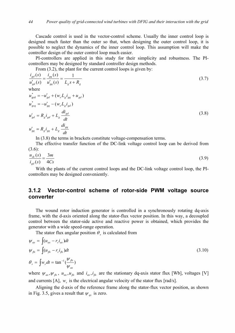
Power quality of grid-connected wind turbines with DFIG and their interaction with the grid
44
Cascade control is used in the vector-control scheme. Usually the inner control loop is designed much faster than the outer so that, when designing the outer control loop, it is possible to neglect the dynamics of the inner control loop. This assumption will make the controller design of the outer control loop much easier.
PI-controllers are applied in this study for their simplicity and robustness. The PI-controllers may be designed by standard controller design methods.
From (3.2), the plant for the current control loops is given by:
gggq
gq
gd
gd
RsLsusi
susi
+=
′=
′1
)()(
)()(
(3.7)
where
dtdi
LiRu
dtdi
LiRu
iLwuu
uiLwuu
gqggqggq
gdggdggd
gdgegqgcq
gdgqgegd
+=′
+=′
−′−=
++′−=
)(
)(*
*gcd
(3.8)
In (3.8) the terms in brackets constitute voltage-compensation terms. The effective transfer function of the DC-link voltage control loop can be derived from
(3.6):
Csm
sisu
gd
dc
43
)()(
= (3.9)
With the plants of the current control loops and the DC-link voltage control loop, the PI-controllers may be designed conveniently.
3.1.2 Vector-control scheme of rotor-side PWM voltage source converter
The wound rotor induction generator is controlled in a synchronously rotating dq-axis
frame, with the d-axis oriented along the stator-flux vector position. In this way, a decoupled control between the stator-side active and reactive power is obtained, which provides the generator with a wide speed-range operation.
The stator flux angular position sθ is calculated from
)(tan
)(
)(
1
s
sss
ssss
ssss
dtw
dtiru
dtiru
α
β
βββ
ααα
ψψ
θ
ψ
ψ
−==
−=
−=
∫
∫∫
(3.10)
where ss βα ψψ , , ss uu βα , and ss ii βα , are the stationary dq-axis stator flux [Wb], voltages [V] and currents [A], sw is the electrical angular velocity of the stator flux [rad/s].
Aligning the d-axis of the reference frame along the stator-flux vector position, as shown in Fig. 3.5, gives a result that qsψ is zero.

Chapter 3. Control schemes and performance of grid-connected wind turbines with DFIG
45
Since the stator is connected to the grid, and the influence of the stator resistance is small,
the stator flux can be considered constant. With this consideration, the DFIG model may be written as:
qrrqr
drrmss
mdr
qrmqss
drmdssmsmdss
drrmsmmslipqr
rqrrqr
qrrslipdr
rdrrdr
dssqss
ds
iL
iLiLL
iLiLiLiLiL
iLiLwdt
diLiru
iLwdt
diLiru
wuuu
σψ
σψ
ψψ
σσ
σσ
ψ
=
+=
+=+===
+++=
−+=
===
2
0
)(
0
(3.11)
where
s
mmm
rs
m
rsslip
es
LL
L
LLL
wwwww
2
2
1
=
−=
−==
σ (3.12)
In this model, su is the magnitude of the stator phase voltage [V], sw is the electrical angular velocity of the stator flux [rad/s], ew is the electrical angular velocity of the stator voltage [rad/s], sψ is the magnitude of the stator flux linkage [Wb], msi is the magnetising current [A] of the generator.
The stator-side active sP and reactive sQ power flow are
dq
sθ
sw
sβψ
sαψ
sψ
α
β
Figure 3.5 Vector diagram of the dq-referenceframe alignment for the rotor-side converter.
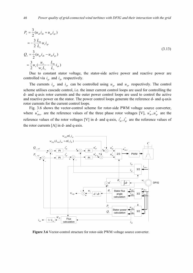
Power quality of grid-connected wind turbines with DFIG and their interaction with the grid
46
)(23
)(2323
)(23
drs
m
ss
ss
qsdsdsqss
qrss
m
qsqsdsdss
iLL
Lwu
u
iuiuQ
iuLL
iuiuP
−=
−=
−=
+=
(3.13)
Due to constant stator voltage, the stator-side active power and reactive power are controlled via qri and dri respectively.
The currents qri and dri can be controlled using qru and dru respectively. The control scheme utilises cascade control, i.e. the inner current control loops are used for controlling the d- and q-axis rotor currents and the outer power control loops are used to control the active and reactive power on the stator. The power control loops generate the reference d- and q-axis rotor currents for the current control loops.
Fig. 3.6 shows the vector-control scheme for rotor-side PWM voltage source converter, where *
abcru are the reference values of the three phase rotor voltages [V], ** , qrdr uu are the
reference values of the rotor voltages [V] in d- and q-axis, ** , qrdr ii are the reference values of the rotor currents [A] in d- and q-axis.
PWM2/3
3/2Stator flux
anglecalculation
PI
PI
mL/1
PI+
-
+
-
swsiαβ
dri
dsψ
+ -
-
+
+
)( drrmsmmslip iLiLw σ+
*qru
*dru
++
*abcru
sθ
qrrslip iLw σ
abcri
msi
DFIG
suαβ
rθ
3/2qri
abcsiabcsu
3/2dqsidqsu
Stator powercalculationsQ
sP
dtd /
∫dt
+
rw
slipw
PI+
-dru′
qru′
*dri
*qrirefsP _
refsQ _
-
-
Fluxcalculation dsi
C
Figure 3.6 Vector-control structure for rotor-side PWM voltage source converter.

Chapter 3. Control schemes and performance of grid-connected wind turbines with DFIG
47
A similar analysis for the control of the dq-axis currents carried out for the grid-side PWM voltage source converter can likewise be done for the control of the dq-axis rotor current. From (3.11), the plant for the current control loops is given by:
rrqr
qr
dr
dr
rsLsusi
susi
+=
′=
′ σ1
)()(
)()(
(3.14)
where
dtdi
Liru
dtdi
Liru
iLiLwuu
iLwuu
qrrqrrqr
drrdrrdr
drrmsmmslipqrqr
qrrslipdrdr
σ
σ
σ
σ
+=′
+=′
++′=
−′=
)(*
*
(3.15)
In Fig. 3.6 the voltage-compensation terms are added to ensure good tracking of the rotor currents.
The effective transfer functions of the stator-side active and reactive power control loops can be derived from (3.13):
ss
m
dr
s
qr
s uLL
sisQ
sisP
23
)()(
)()(
−== (3.16)
With the plants of the current control loops and the power control loops, the PI-controllers may be designed easily.
3.1.3 PI-controller design
The practising control engineer often has greater knowledge and experience in designing
continuous-time rather than discrete-time controllers. Moreover, many practical systems already incorporate continuous-time controllers. Therefore, the continuous-time PI-controller design methods are applied in this investigation.
There are a number of standard methods for designing PI-controllers, such as Ziegler-Nichols tuning [5], root locus [6, 7], Bode [7, 8], pole-placement [9] and internal model control [10], etc. In this study, the pole-placement method is utilised, for its straightforwardness and simplicity, to design PI-controllers in current control loops and power control loops. Internal model control, which is considered as a robust control method, has been used for AC machine control [11, 12, 13, 14, 15]. The benefit of the internal model control is that the controller parameters are expressed directly in the machine parameters and the desired closed-loop rise time. Thus internal model control is applied to design the DC-link voltage controller.
Design of PI-controllers in current control loops and power control loops In the vector-control scheme of the grid-side PWM voltage source converter, the d- and q-
axis line currents are decoupled for controlling the DC-link voltage and the reactive power flow between the grid and the grid-side converter respectively. In the vector-control scheme of the rotor-side PWM voltage source converter, the d- and q-axis rotor currents are decoupled

Power quality of grid-connected wind turbines with DFIG and their interaction with the grid
48
for individual stator-side active and reactive power control. The voltage-compensation terms are used for decoupling the current control loops.
It is seen from the transfer functions of the current control loops that all the plants for the current control loops are stable with only one single dominant nonzero pole. In this condition, a straightforward approach for designing a PI-controller is to place the zero of the PI-controller to cancel (or approximately cancel) the dominant pole of the plant. This method is called pole-placement [9]. Thus the system is changed from a type 0 to a type 1 system.
Assuming ideal decoupling between the d- and q-axis currents, the current control loop is shown in Fig. 3.7.
The open-loop transfer function of the current control loop is
)()(
)(pssaskk
sG icpc
+
+= (3.17)
Let paic = :
skk
sG pc=)( (3.18)
The closed-loop transfer function is
kkskk
sGsG
pc
pc
+=
+ )(1)( (3.19)
This is a first order system and the bandwidth of the first order system is kk pcn =ω (3.20)
The relationship between the bandwidth and the rise time (10-90%) for a first order system is 1/9ln rn t=ω [15]. Thus, the rise time of the system step response is
kkt
pcr
9ln1 = (3.21)
Therefore, the pck can be determined as
%)1(9ln
1
mkt
kr
pc += (3.22)
where %m is the design margin, which guarantees the required rise time will be obtained. The cascade control scheme with an inner rotor current control loop and an outer power
control loop is shown in Fig. 3.8, where k ′ represents the power control loop plant
+ - sask icpc )( +
PI controller
psk+
Plant
dqi*dqi
Figure 3.7 Schematic diagram of the current control loop of thegenerator.

Chapter 3. Control schemes and performance of grid-connected wind turbines with DFIG
49
ss
m uLL
k23
−=′ (3.23)
Since the closed-loop transfer function of the current control loop is expressed as (3.19), the control scheme shown in Fig. 3.8 may be simplified as Fig. 3.9.
The PI-controllers in the power control loops can be designed in a similar way to the
design of the PI-controllers in the current control loops. The integral gain and proportional gain can be found as
%)1(9ln
2
mtkkk
k
kka
rpcpp
pcip
+′
=
=
(3.24)
where 2rt is the rise time of the power control loop step response [s], and m is the design margin.
Design of the PI-controller in the DC-link voltage control loop For its straightforwardness and simplicity, the pole-placement method is applied for
designing PI-controllers in current control loops and power control loops. It is seen from the transfer function of the DC-link voltage control loop that the plant has one single zero pole, where the pole-placement method cannot be used directly. Therefore, another method has been employed to design the PI-controller in the DC-link voltage control loop.
Internal model control, which is considered as a robust control method, has been used for AC machine control [11, 12, 13, 14, 15]. The benefit of the internal model control is that the controller parameters are expressed directly in the machine parameter and the desired closed-loop rise time. In this investigation, internal model control is utilized to design the DC-link voltage controller.
+ - sask icpc )( +
PI controller
psk+
Plant
dqi*dqi
k ′s
ask ippp )( +
PI controller
-+
ss QP ,refsrefs QP __ ,
Plant
Figure 3.8 Schematic diagram of the cascade control scheme of the generator.
kkskk
pc
pc
+dqi
k ′s
ask ippp )( +
PI controller
-+ss QP ,refsrefs QP __ ,
Plant
*dqi
Figure 3.9 Simplified diagram of the cascade control scheme of the generator.
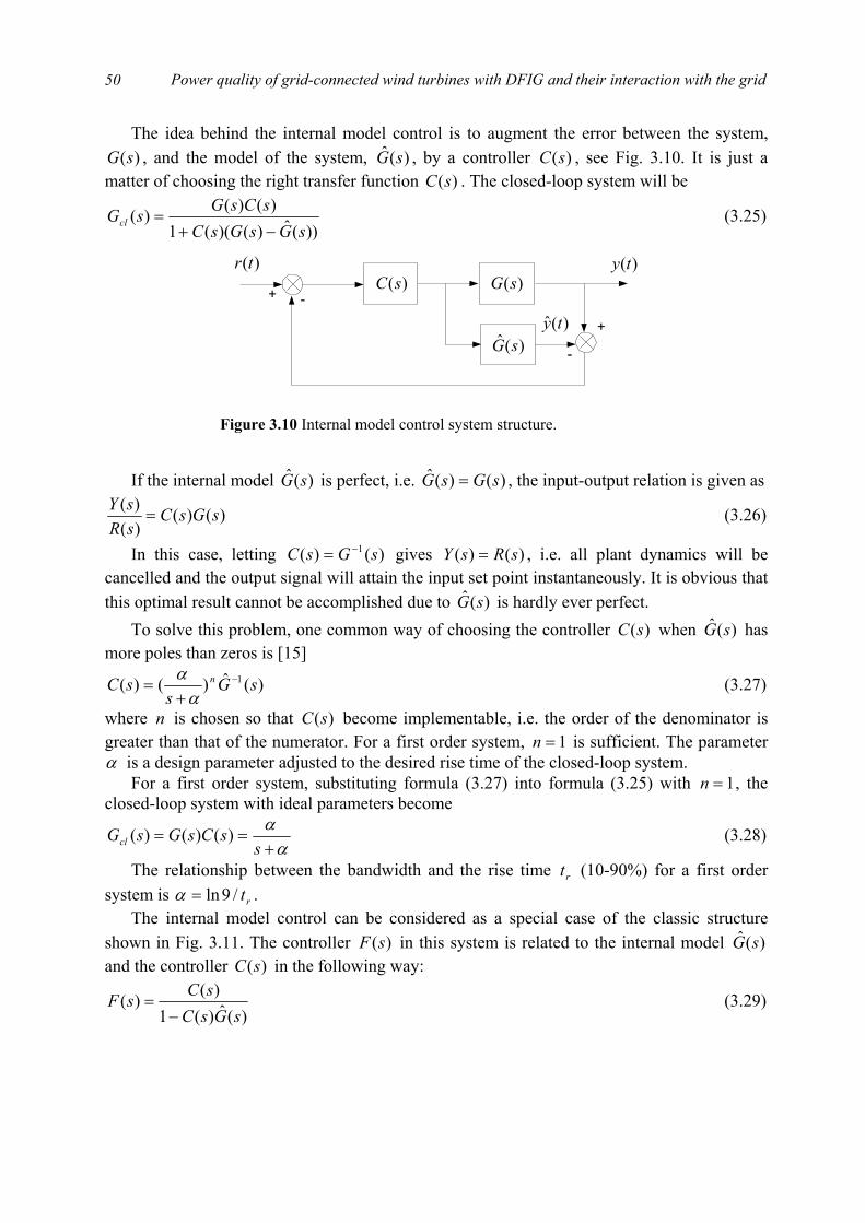
Power quality of grid-connected wind turbines with DFIG and their interaction with the grid
50
The idea behind the internal model control is to augment the error between the system, )(sG , and the model of the system, )(ˆ sG , by a controller )(sC , see Fig. 3.10. It is just a
matter of choosing the right transfer function )(sC . The closed-loop system will be
))(ˆ)()((1)()()(
sGsGsCsCsGsGcl−+
= (3.25)
If the internal model )(ˆ sG is perfect, i.e. )()(ˆ sGsG = , the input-output relation is given as
)()()()( sGsC
sRsY
= (3.26)
In this case, letting )()( 1 sGsC −= gives )()( sRsY = , i.e. all plant dynamics will be cancelled and the output signal will attain the input set point instantaneously. It is obvious that this optimal result cannot be accomplished due to )(ˆ sG is hardly ever perfect.
To solve this problem, one common way of choosing the controller )(sC when )(ˆ sG has more poles than zeros is [15]
)(ˆ)()( 1 sGs
sC n −
+=
αα (3.27)
where n is chosen so that )(sC become implementable, i.e. the order of the denominator is greater than that of the numerator. For a first order system, 1=n is sufficient. The parameter α is a design parameter adjusted to the desired rise time of the closed-loop system.
For a first order system, substituting formula (3.27) into formula (3.25) with 1=n , the closed-loop system with ideal parameters become
αα+
==s
sCsGsGcl )()()( (3.28)
The relationship between the bandwidth and the rise time rt (10-90%) for a first order system is rt/9ln=α .
The internal model control can be considered as a special case of the classic structure shown in Fig. 3.11. The controller )(sF in this system is related to the internal model )(ˆ sG and the controller )(sC in the following way:
)(ˆ)(1)()(
sGsCsCsF
−= (3.29)
+ -)(sC
)(ty)(tr)(sG
)(ˆ sG+
-
)(ˆ ty
Figure 3.10 Internal model control system structure.
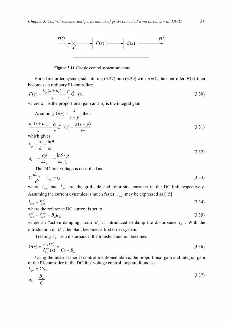
Chapter 3. Control schemes and performance of grid-connected wind turbines with DFIG
51
For a first order system, substituting (3.27) into (3.29) with 1=n , the controller )(sF then
becomes an ordinary PI-controller:
)(ˆ)()( 1 sG
ssask
sF ip −=+
=α (3.30)
where pk is the proportional gain and ia is the integral gain.
Assuming ps
ksG−
=)(ˆ , then
kspssG
ssask ip )()(ˆ)( 1 −
==+ − αα (3.31)
which gives
rppi
rp
tkkp
kkpa
ktkk
⋅−=−=
==
9ln
9ln
α
α
(3.32)
The DC-link voltage is described as
dcrdcgdc ii
dtdu
C −= (3.33)
where dcgi and dcri are the grid-side and rotor-side currents in the DC-link respectively. Assuming the current dynamics is much faster, dcgi may be expressed as [15]
refdcgdcg ii = (3.34)
where the reference DC current is set to dca
refdcg
refdcg uBii −′= (3.35)
where an “active damping” term aB is introduced to damp the disturbance dcri . With the introduction of aB , the plant becomes a first order system.
Treating dcri as a disturbance, the transfer function becomes
aref
dcg
dc
BCssisu
sG+
=′
=1
)()(
)( (3.36)
Using the internal model control mentioned above, the proportional gain and integral gain of the PI-controller in the DC-link voltage control loop are found as
CB
a
Ck
aie
epe
=
= α (3.37)
+ -)(sF
)(ty)(tr)(sG
Figure 3.11 Classic control system structure.
Power quality of grid-connected wind turbines with DFIG and their interaction with the grid
52
where eα is the desired closed-loop bandwidth of the DC-link voltage control loop. The closed-loop dynamic is then described as
e
ecl s
sGα
α+
=)( (3.38)
Fig. 3.12 shows a block diagram of the DC-link voltage control system. In this figure, )(sD represents the disturbance, i.e. dcri .
Choosing ea CB α= [15], and re
e t9ln
=α yields
reie
repe
ta
tCk
9ln
9ln
=
⋅=
(3.39)
3.2 Pitch control scheme
The aerodynamic model of the wind turbine has shown that the power coefficient is
strongly influenced by variation of the blade pitch with respect to the direction of the wind or to the plane of rotation. Small changes in the pitch angle can have a dramatic effect on the output power.
In low to moderate wind speeds, the turbine should simply try to produce as much power as possible, so there is generally no need to vary the pitch angle. The pitch angle should only be at its optimum value to produce maximum power. In high wind speeds, pitch control provides a very effective means of regulating the aerodynamic power and loads produced by the rotor so that the design limits are not exceeded.
To put the blades into the necessary position, various control systems are employed. Reference [16] illustrates a simple pitch mechanism driven by an AC servomotor which subjects to external pitching moments (disturbances to the system). The blade and pitch mechanism model includes moments from the spring and viscous friction. The torque from an AC servo motor can be modeled as a linear combination of terms that are a function of the motor speed and of the applied voltage. In the model presented here, the motor torque and
+ +
refdcgi
sask iepe )( +
-+
refdcu _
)(sD
-
aB
)(sGdcu
Figure 3.12 Block diagram of the DC-link voltage control system.

Chapter 3. Control schemes and performance of grid-connected wind turbines with DFIG
53
speed are referred to the blade side of the pitch mechanism. The differential equation for this system has the system dynamic terms on the left and the external torques from the motor and disturbance on the right:
pQmtkvKBJ +′+=+′+′′ θθθθ )( (3.40) where θ is the pitch angle, J is total inertia of the blade and motor, B is the pitch system coefficient of viscous friction, K is the pitch system spring constant, k is the slope of the torque-voltage curve for motor/pitch mechanism combination, )(tv is the voltage applied to motor terminals, m is the slope of the torque-speed curve for motor/pitch mechanism combination and pQ is a pitching moment due to dynamic and aerodynamic forces that acts as a disturbance in the system.
In steady state, i.e. the derivatives of the pitch angle are zero and )(tv is a constant value, the differential equation becomes
KQ
vKk p+=θ (3.41)
Assuming that the airfoil designer has tried to minimize any pitching moment, one could design a control system that applied a specific voltage to the motor for a desired reference pitch angle, refθ :
refkKv θ= (3.42)
In this case, the differential equation for the open-loop system is
pref QKKmBJ +=+′−+′′ θθθθ )( (3.43)
A block diagram for this system is shown in Fig. 3.13. If one assumes that all derivatives and the pitching disturbance torque are zero, it can be seen that the steady state response of the system to a desired pitch angle command is, indeed, the desired pitch angle.
In practice open-loop control systems may not be able to meet the control requirements
sufficiently. Closed-loop control system can be used to improve system performance without significantly complicating the control system. The closed-loop pitch control system with a PI-controller is shown in Fig. 3.14.
The differential equation for the closed-loop system is
prefirefpip QkkkkkkkkKmBJ ′++′=+′++′′−+′′′ θθθθθθ )()( (3.44)
where pk and ik are the proportional gain and integral gain of the PI-controller respectively. The corresponding pitch control system is shown in Fig. 3.15.
Motor and bladedynamics
Voltage
Electricaltorque
Pitchingmoment
++
refθ θkK
k
Figure 3.13 Open-loop pitch control mechanism.
Power quality of grid-connected wind turbines with DFIG and their interaction with the grid
54
The transfer function of the closed-loop system is
ip
p
ip
refip
kkskkKsmBJsssQ
kkskkKsmBJsskskk
s+++−+
++++−+
+=
)()()(
)()()()(
)( 2323
θθ (3.45)
Applying the parameters recommended in [16]: 161=J , 41=− mB , 2== ip kk , and 1== kK , the transfer function can be written as the following formula, which will be used in
the developed wind turbine model.
)7.453.3)(7.0()(16
)7.453.3)(7.0()()1(32
)( 22 ++++
+++
+=
sssssQ
sssss
s prefθθ (3.46)
Assuming the pitching moment has been minimized, i.e. 0=pQ , the transfer function of the closed-loop system becomes
)7.453.3)(7.0()()1(32
)( 2 +++
+=
sssss
s refθθ (3.47)
3.3 Performance of the wind turbine
3.3.1 Wind turbine description
The wind turbine in this study is a 2 MW, horizontal axis, three-bladed, upwind wind
turbine with speed control and pitch control. A 4-pole DFIG, using back-to-back PWM voltage source converters in the rotor circuit, is applied in the wind turbine. The parameters used in the wind turbine model are very close to that of a commercial wind turbine.
PI-Controller Motor and bladedynamics
Voltage
Electricaltorque
Pitchingmoment
++
+
-refθ θk
Figure 3.14 Closed-loop pitch control mechanism.
++
+
-refθ θskk i
p +KsmBJs +−+ )(
12
pQ
k
Figure 3.15 Closed-loop pitch control system.
Chapter 3. Control schemes and performance of grid-connected wind turbines with DFIG
55
The power curve of the wind turbine is shown in Fig. 3.16. It is seen from Fig. 3.16 that the wind turbine operates between the cut-in speed, 4 m/s, and the cut-out speed, 25 m/s. The output power of the wind turbine reaches the rated power, 2 MW, when the wind speed approaches the rated value, 17 m/s. The power curve is selected to achieve maximum energy capture in low wind speeds and, at the same time, the rated power in high wind speeds.
The complete power-speed characteristic applied in the wind turbine is illustrated in Fig. 3.17.
Section BC represents the optimum operation range. Within this range, the rotor speed is
adjusted in proportion to the wind speed so that the optimal tip speed ratio is maintained which leads to a maximum wind power capture, while the pitch angle is kept constant. When the rotational speed of the generator rotor approaches the point D, the output power of the wind turbine reaches the rated value. At the point D, the rotational speed of the generator rotor is kept constant at the rated value as well as the wind turbine output power.
Figure 3.16 Power curve of the wind turbine.
Figure 3.17 Power-speed characteristic of the pitch controlled windturbine.
Power quality of grid-connected wind turbines with DFIG and their interaction with the grid
56
It is not practicable to maintain optimum power extraction from cut-in up to the rated speed. Therefore, section AB and CD account for the transition ranges. The reason why section AB and CD are not vertical is that, if so, there will exist some problems because the desired power is not uniquely defined at minimum and rated generator rotor speed. The slight changes of the generator rotor speed around its minimum or its rated value will cause large power fluctuations. The power-speed characteristic shown in Fig. 3.17 is capable of solving the problems effectively.
The parameters of the DFIG applied in the wind turbine are shown in details in Table 3.1.
Table 3.1 Generator parameters
Parameter Value Rated power ( ratedP ) 2 MW
Rated voltage ( ratedU ) 0.69 kV Base angular frequency ( ratedw ) 314.16 rad/s
Stator/ rotor turns ratio ( n ) 0.4333 Angular moment of inertia ( WGJ ) 1.9914 p. u.
Mechanical damping ( D ) 0.02 p. u. Stator resistance ( sr ) 0.0175 p. u. Rotor resistance ( rr ) 0.019 p. u.
Stator leakage inductance ( lsL ) 0.2571 p. u. Rotor leakage inductance ( lrL ) 0.295 p. u.
Mutual inductance ( mL ) 6.921 p. u. The gear ratio of the wind turbine is 100.5. The parameters of the inductor in series with
the grid-side PWM voltage source converter are: HLR gg 0004.0,0084.0 =Ω= . The value of the capacitor in the DC-link is set as: FC 03.0= .
For the grid-side PWM voltage source converter, the parameters of the PI-controllers in the current control loops may be obtained based on the plant shown in (3.7) and the pole-placement method introduced in § 3.1.3. The parameters of the PI controller in the DC-link voltage control loop may be calculated out with (3.39). Setting the rise time of the current control loops and the DC-link voltage control loop respectively as: stst rer 02.0,002.01 == , and applying a 20% design margin, the parameters of the PI-controllers in the vector-control scheme for the grid-side converter are listed in table 3.2, where the PI controller output limits are set as approximately 1.2 times the nominal values.
Table 3.2 PI-controller parameters for grid-side converter
Proportional gain
( pk ) Integral gain
( ia ) Upper limit Lower limit
Current loops 0.5273 20.9440 470 -470 DC-link voltage loop 0.3296 10.9861 970 -970
Similarly, with respect to the rotor-side PWM voltage source converter, the parameters of
the PI-controllers in the current control loops may be obtained based on the plant shown in

Chapter 3. Control schemes and performance of grid-connected wind turbines with DFIG
57
(3.14) and the pole-placement method introduced in § 3.1.3. The parameters of the PI controllers in the power control loops may be calculated out with (3.24). Setting the rise time of the current control loops and the power control loops respectively as:
stst rr 02.0,002.0 21 == , and applying a 20% design margin, the parameters of the PI-controllers in the vector-control scheme for the rotor-side converter are listed in table 3.3, where the PI controller output limits are set as approximately 1.2 times the nominal values.
Table 3.3 PI-controller parameters for rotor-side converter
Proportional gain
( pk ) Integral gain
( ia ) Upper limit Lower limit
Current loops 0.5275 9.0240 710 -710 Power loops -1.2037e-4 1.3183e3 970 -970
3.3.2 Wind simulation
The wind applied in this study is produced according to the wind model explained in
Chapter 2. Since only one wind turbine will be considered in this investigation, the park scale wind model is not included and only the rotor wind model is applied.
According to the wind model, different mean values and different turbulence intensities result in different wind speeds. The wind speeds with different mean values are shown in Fig. 3.18, while the turbulence intensity is kept at 0.1. Though the turbulence intensity is the same, larger mean wind speed results in a wider variation of the wind speed.
The wind speeds with different turbulence intensities are shown in Fig. 3.19, while the mean wind speed is kept at 10 m/s. It is seen from Fig. 3.19 that larger turbulence intensity leads to a wider variation of the wind speed.
Figure 3.18 Wind speeds with different mean values (The turbulence intensity is kept at 0.1).
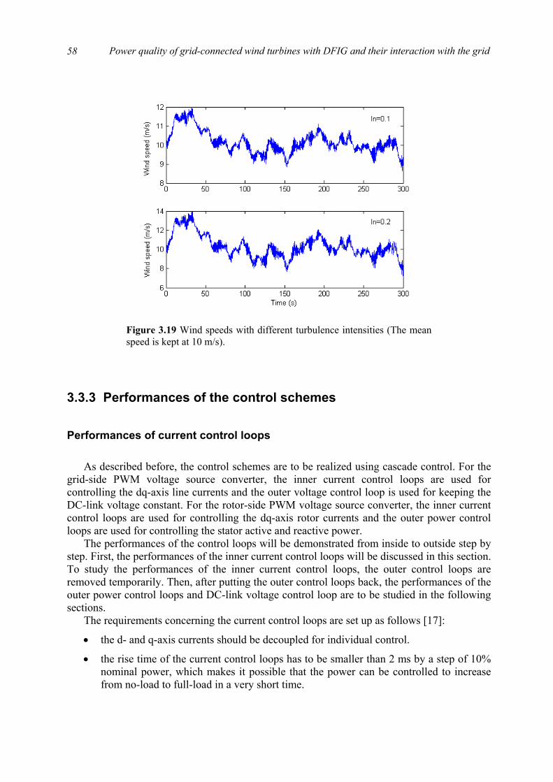
Power quality of grid-connected wind turbines with DFIG and their interaction with the grid
58
3.3.3 Performances of the control schemes
Performances of current control loops As described before, the control schemes are to be realized using cascade control. For the
grid-side PWM voltage source converter, the inner current control loops are used for controlling the dq-axis line currents and the outer voltage control loop is used for keeping the DC-link voltage constant. For the rotor-side PWM voltage source converter, the inner current control loops are used for controlling the dq-axis rotor currents and the outer power control loops are used for controlling the stator active and reactive power.
The performances of the control loops will be demonstrated from inside to outside step by step. First, the performances of the inner current control loops will be discussed in this section. To study the performances of the inner current control loops, the outer control loops are removed temporarily. Then, after putting the outer control loops back, the performances of the outer power control loops and DC-link voltage control loop are to be studied in the following sections.
The requirements concerning the current control loops are set up as follows [17]:
• the d- and q-axis currents should be decoupled for individual control.
• the rise time of the current control loops has to be smaller than 2 ms by a step of 10% nominal power, which makes it possible that the power can be controlled to increase from no-load to full-load in a very short time.
Figure 3.19 Wind speeds with different turbulence intensities (The meanspeed is kept at 10 m/s).
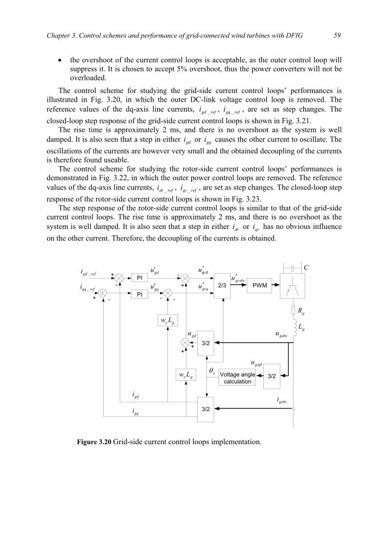
Chapter 3. Control schemes and performance of grid-connected wind turbines with DFIG
59
• the overshoot of the current control loops is acceptable, as the outer control loop will suppress it. It is chosen to accept 5% overshoot, thus the power converters will not be overloaded.
The control scheme for studying the grid-side current control loops’ performances is illustrated in Fig. 3.20, in which the outer DC-link voltage control loop is removed. The reference values of the dq-axis line currents, refgqrefgd ii __ , , are set as step changes. The closed-loop step response of the grid-side current control loops is shown in Fig. 3.21.
The rise time is approximately 2 ms, and there is no overshoot as the system is well damped. It is also seen that a step in either gdi or gqi causes the other current to oscillate. The oscillations of the currents are however very small and the obtained decoupling of the currents is therefore found useable.
The control scheme for studying the rotor-side current control loops’ performances is demonstrated in Fig. 3.22, in which the outer power control loops are removed. The reference values of the dq-axis line currents, refqrrefdr ii __ , , are set as step changes. The closed-loop step response of the rotor-side current control loops is shown in Fig. 3.23.
The step response of the rotor-side current control loops is similar to that of the grid-side current control loops. The rise time is approximately 2 ms, and there is no overshoot as the system is well damped. It is also seen that a step in either dri or qri has no obvious influence on the other current. Therefore, the decoupling of the currents is obtained.
PWM2/3
3/2Voltage anglecalculation
3/2
3/2
PI
PI
ge Lw
ge Lw
refgdi _ +
-
gdu′
gdi
gqi
refgqi _ gqu′
+ -
-
+
++
gdu
*gcdu
*gcqu
- -
*gcabcu
gL
gR
eθ
gabcu
gabci
αβgu
C
Figure 3.20 Grid-side current control loops implementation.
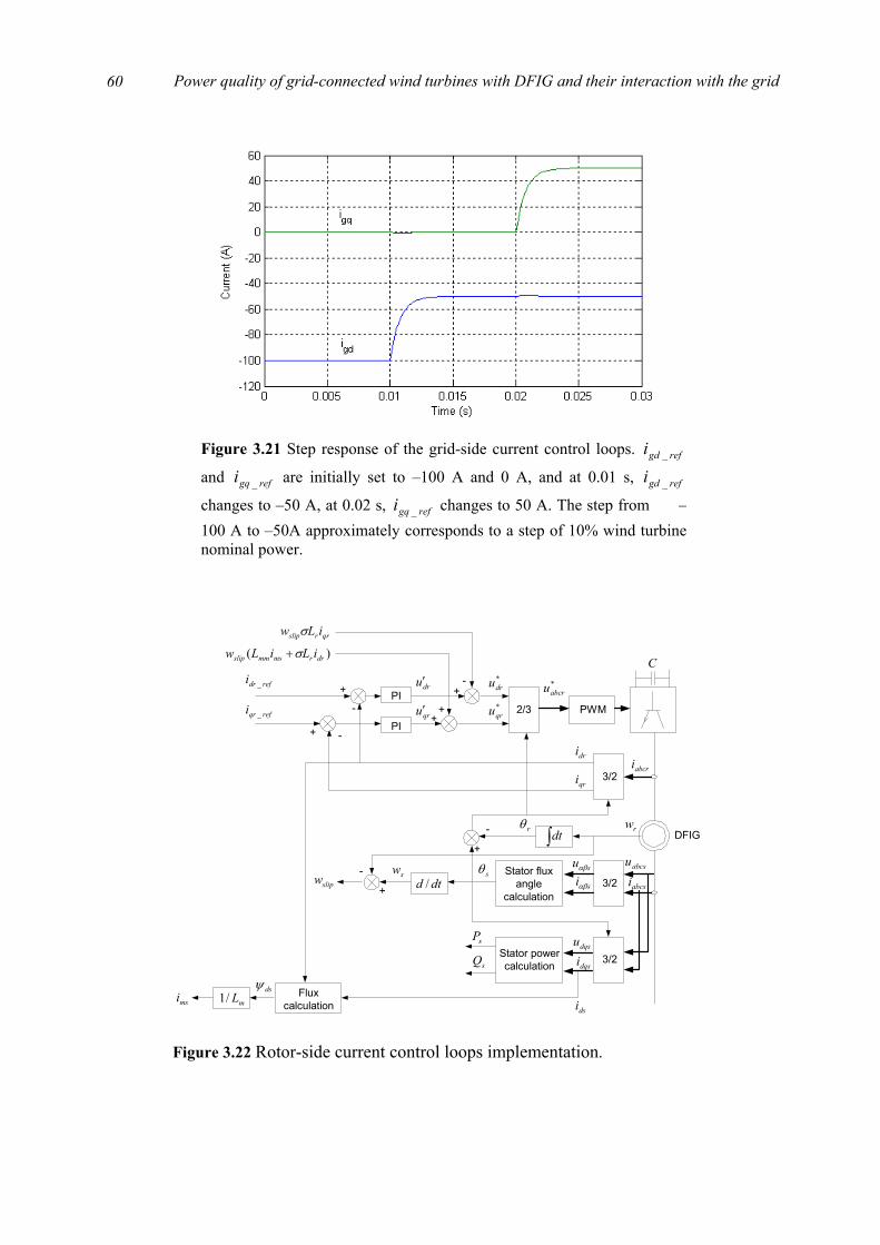
Power quality of grid-connected wind turbines with DFIG and their interaction with the grid
60
Figure 3.21 Step response of the grid-side current control loops. refgdi _
and refgqi _ are initially set to –100 A and 0 A, and at 0.01 s, refgdi _
changes to –50 A, at 0.02 s, refgqi _ changes to 50 A. The step from –100 A to –50A approximately corresponds to a step of 10% wind turbine nominal power.
PWM2/3
3/2Stator flux
anglecalculation
PI
PI
mL/1
-
+
-
swsiαβ
dri
dsψ
+ -
-
+
+
)( drrmsmmslip iLiLw σ+
*qru
*dru
++
*abcru
sθ
qrrslip iLw σ
abcri
msi
DFIG
suαβ
rθ
3/2qri
abcsiabcsu
3/2dqsidqsu
Stator powercalculationsQ
sP
dtd /
∫dt
+
rw
slipw
-dru′
qru′
refdri _
refqri _
Fluxcalculation dsi
C
Figure 3.22 Rotor-side current control loops implementation.
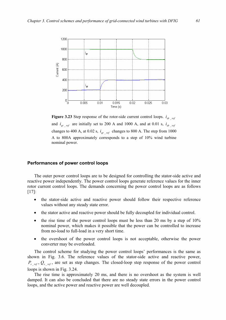
Chapter 3. Control schemes and performance of grid-connected wind turbines with DFIG
61
Performances of power control loops The outer power control loops are to be designed for controlling the stator-side active and
reactive power independently. The power control loops generate reference values for the inner rotor current control loops. The demands concerning the power control loops are as follows [17]:
• the stator-side active and reactive power should follow their respective reference values without any steady state error.
• the stator active and reactive power should be fully decoupled for individual control.
• the rise time of the power control loops must be less than 20 ms by a step of 10% nominal power, which makes it possible that the power can be controlled to increase from no-load to full-load in a very short time.
• the overshoot of the power control loops is not acceptable, otherwise the power converter may be overloaded.
The control scheme for studying the power control loops’ performances is the same as shown in Fig. 3.6. The reference values of the stator-side active and reactive power,
refsrefs QP __ , , are set as step changes. The closed-loop step response of the power control loops is shown in Fig. 3.24.
The rise time is approximately 20 ms, and there is no overshoot as the system is well damped. It can also be concluded that there are no steady state errors in the power control loops, and the active power and reactive power are well decoupled.
Figure 3.23 Step response of the rotor-side current control loops. refdri _
and refqri _ are initially set to 200 A and 1000 A, and at 0.01 s, refdri _
changes to 400 A, at 0.02 s, refqri _ changes to 800 A. The step from 1000 A to 800A approximately corresponds to a step of 10% wind turbinenominal power.
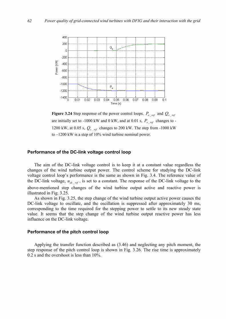
Power quality of grid-connected wind turbines with DFIG and their interaction with the grid
62
Performance of the DC-link voltage control loop The aim of the DC-link voltage control is to keep it at a constant value regardless the
changes of the wind turbine output power. The control scheme for studying the DC-link voltage control loop’s performance is the same as shown in Fig. 3.4. The reference value of the DC-link voltage, refdcu _ , is set to a constant. The response of the DC-link voltage to the above-mentioned step changes of the wind turbine output active and reactive power is illustrated in Fig. 3.25.
As shown in Fig. 3.25, the step change of the wind turbine output active power causes the DC-link voltage to oscillate, and the oscillation is suppressed after approximately 30 ms, corresponding to the time required for the stepping power to settle to its new steady state value. It seems that the step change of the wind turbine output reactive power has less influence on the DC-link voltage.
Performance of the pitch control loop Applying the transfer function described as (3.46) and neglecting any pitch moment, the
step response of the pitch control loop is shown in Fig. 3.26. The rise time is approximately 0.2 s and the overshoot is less than 10%.
Figure 3.24 Step response of the power control loops. refsP _ and refsQ _
are initially set to -1000 kW and 0 kW, and at 0.01 s, refsP _ changes to -
1200 kW, at 0.05 s, refsQ _ changes to 200 kW. The step from -1000 kWto –1200 kW is a step of 10% wind turbine nominal power.
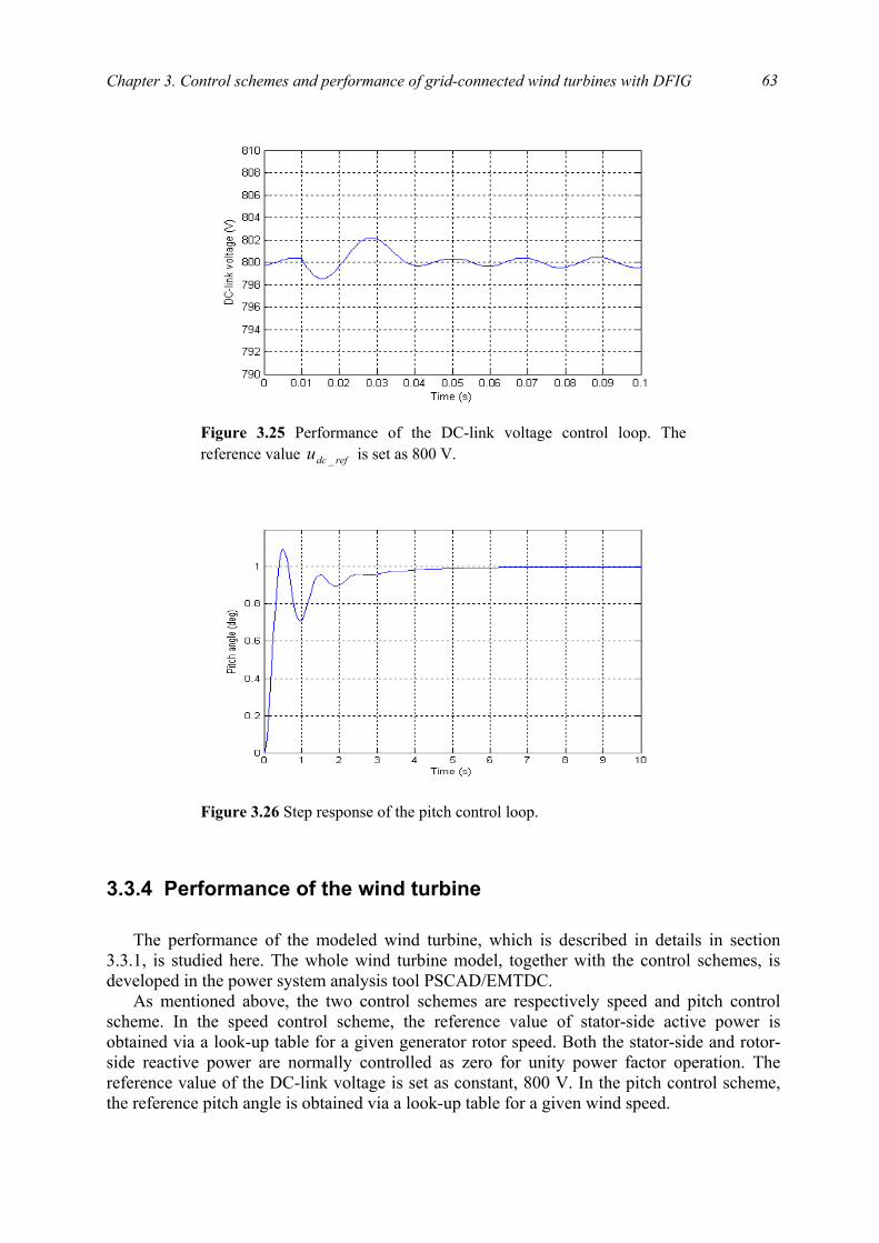
Chapter 3. Control schemes and performance of grid-connected wind turbines with DFIG
63
3.3.4 Performance of the wind turbine The performance of the modeled wind turbine, which is described in details in section
3.3.1, is studied here. The whole wind turbine model, together with the control schemes, is developed in the power system analysis tool PSCAD/EMTDC.
As mentioned above, the two control schemes are respectively speed and pitch control scheme. In the speed control scheme, the reference value of stator-side active power is obtained via a look-up table for a given generator rotor speed. Both the stator-side and rotor-side reactive power are normally controlled as zero for unity power factor operation. The reference value of the DC-link voltage is set as constant, 800 V. In the pitch control scheme, the reference pitch angle is obtained via a look-up table for a given wind speed.
Figure 3.25 Performance of the DC-link voltage control loop. The reference value refdcu _ is set as 800 V.
Figure 3.26 Step response of the pitch control loop.
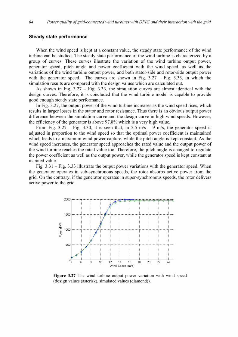
Power quality of grid-connected wind turbines with DFIG and their interaction with the grid
64
Steady state performance When the wind speed is kept at a constant value, the steady state performance of the wind
turbine can be studied. The steady state performance of the wind turbine is characterized by a group of curves. These curves illustrate the variation of the wind turbine output power, generator speed, pitch angle and power coefficient with the wind speed, as well as the variations of the wind turbine output power, and both stator-side and rotor-side output power with the generator speed. The curves are shown in Fig. 3.27 – Fig. 3.33, in which the simulation results are compared with the design values which are calculated out.
As shown in Fig. 3.27 – Fig. 3.33, the simulation curves are almost identical with the design curves. Therefore, it is concluded that the wind turbine model is capable to provide good enough steady state performance.
In Fig. 3.27, the output power of the wind turbine increases as the wind speed rises, which results in larger losses in the stator and rotor resistance. Thus there is an obvious output power difference between the simulation curve and the design curve in high wind speeds. However, the efficiency of the generator is above 97.8% which is a very high value.
From Fig. 3.27 – Fig. 3.30, it is seen that, in 5.5 m/s – 9 m/s, the generator speed is adjusted in proportion to the wind speed so that the optimal power coefficient is maintained which leads to a maximum wind power capture, while the pitch angle is kept constant. As the wind speed increases, the generator speed approaches the rated value and the output power of the wind turbine reaches the rated value too. Therefore, the pitch angle is changed to regulate the power coefficient as well as the output power, while the generator speed is kept constant at its rated value.
Fig. 3.31 – Fig. 3.33 illustrate the output power variations with the generator speed. When the generator operates in sub-synchronous speeds, the rotor absorbs active power from the grid. On the contrary, if the generator operates in super-synchronous speeds, the rotor delivers active power to the grid.
Figure 3.27 The wind turbine output power variation with wind speed(design values (asterisk), simulated values (diamond)).
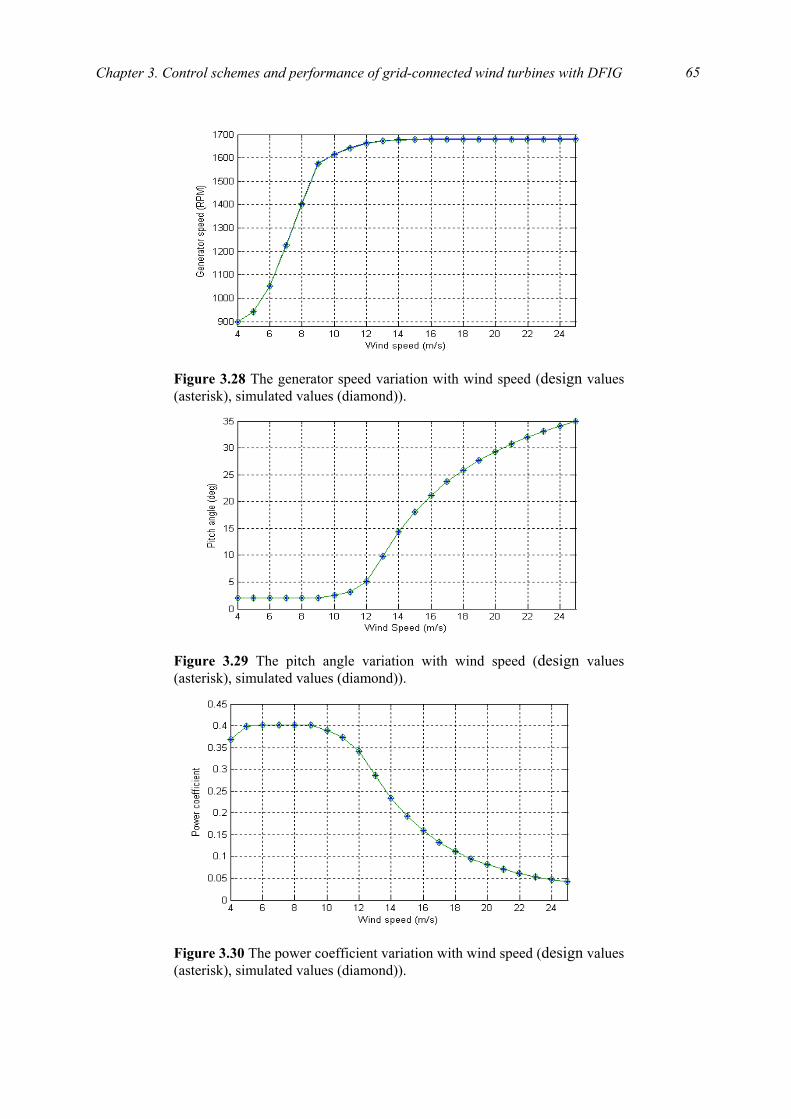
Chapter 3. Control schemes and performance of grid-connected wind turbines with DFIG
65
Figure 3.28 The generator speed variation with wind speed (design values (asterisk), simulated values (diamond)).
Figure 3.29 The pitch angle variation with wind speed (design values (asterisk), simulated values (diamond)).
Figure 3.30 The power coefficient variation with wind speed (design values (asterisk), simulated values (diamond)).
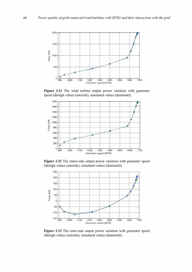
Power quality of grid-connected wind turbines with DFIG and their interaction with the grid
66
Figure 3.31 The wind turbine output power variation with generatorspeed (design values (asterisk), simulated values (diamond)).
Figure 3.32 The stator-side output power variation with generator speed (design values (asterisk), simulated values (diamond)).
Figure 3.33 The rotor-side output power variation with generator speed(design values (asterisk), simulated values (diamond)).
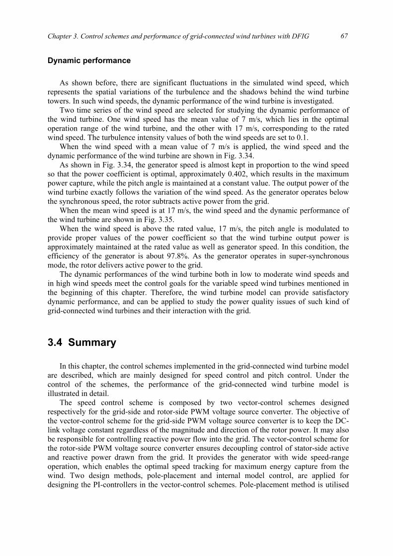
Chapter 3. Control schemes and performance of grid-connected wind turbines with DFIG
67
Dynamic performance As shown before, there are significant fluctuations in the simulated wind speed, which
represents the spatial variations of the turbulence and the shadows behind the wind turbine towers. In such wind speeds, the dynamic performance of the wind turbine is investigated.
Two time series of the wind speed are selected for studying the dynamic performance of the wind turbine. One wind speed has the mean value of 7 m/s, which lies in the optimal operation range of the wind turbine, and the other with 17 m/s, corresponding to the rated wind speed. The turbulence intensity values of both the wind speeds are set to 0.1.
When the wind speed with a mean value of 7 m/s is applied, the wind speed and the dynamic performance of the wind turbine are shown in Fig. 3.34.
As shown in Fig. 3.34, the generator speed is almost kept in proportion to the wind speed so that the power coefficient is optimal, approximately 0.402, which results in the maximum power capture, while the pitch angle is maintained at a constant value. The output power of the wind turbine exactly follows the variation of the wind speed. As the generator operates below the synchronous speed, the rotor subtracts active power from the grid.
When the mean wind speed is at 17 m/s, the wind speed and the dynamic performance of the wind turbine are shown in Fig. 3.35.
When the wind speed is above the rated value, 17 m/s, the pitch angle is modulated to provide proper values of the power coefficient so that the wind turbine output power is approximately maintained at the rated value as well as generator speed. In this condition, the efficiency of the generator is about 97.8%. As the generator operates in super-synchronous mode, the rotor delivers active power to the grid.
The dynamic performances of the wind turbine both in low to moderate wind speeds and in high wind speeds meet the control goals for the variable speed wind turbines mentioned in the beginning of this chapter. Therefore, the wind turbine model can provide satisfactory dynamic performance, and can be applied to study the power quality issues of such kind of grid-connected wind turbines and their interaction with the grid.
3.4 Summary
In this chapter, the control schemes implemented in the grid-connected wind turbine model
are described, which are mainly designed for speed control and pitch control. Under the control of the schemes, the performance of the grid-connected wind turbine model is illustrated in detail.
The speed control scheme is composed by two vector-control schemes designed respectively for the grid-side and rotor-side PWM voltage source converter. The objective of the vector-control scheme for the grid-side PWM voltage source converter is to keep the DC-link voltage constant regardless of the magnitude and direction of the rotor power. It may also be responsible for controlling reactive power flow into the grid. The vector-control scheme for the rotor-side PWM voltage source converter ensures decoupling control of stator-side active and reactive power drawn from the grid. It provides the generator with wide speed-range operation, which enables the optimal speed tracking for maximum energy capture from the wind. Two design methods, pole-placement and internal model control, are applied for designing the PI-controllers in the vector-control schemes. Pole-placement method is utilised
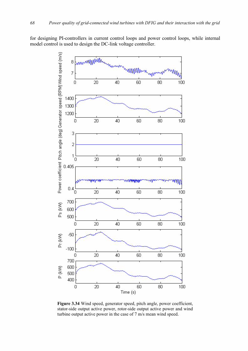
Power quality of grid-connected wind turbines with DFIG and their interaction with the grid
68
for designing PI-controllers in current control loops and power control loops, while internal model control is used to design the DC-link voltage controller.
Figure 3.34 Wind speed, generator speed, pitch angle, power coefficient,stator-side output active power, rotor-side output active power and windturbine output active power in the case of 7 m/s mean wind speed.
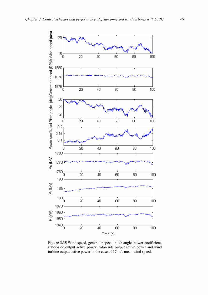
Chapter 3. Control schemes and performance of grid-connected wind turbines with DFIG
69
Figure 3.35 Wind speed, generator speed, pitch angle, power coefficient,stator-side output active power, rotor-side output active power and wind turbine output active power in the case of 17 m/s mean wind speed.
Power quality of grid-connected wind turbines with DFIG and their interaction with the grid
70
The pitch control scheme simulates a simple pitch mechanism driven by an AC servomotor, which is employed to regulate the aerodynamic power produced by the wind turbine.
The performances of the control schemes, respectively current control loops, power control loops, DC-link voltage control loop and pitch control loop, are illustrated, which meet the design requirements. The wind turbine is capable of providing satisfactory steady state and dynamic performances, which makes it possible that the wind turbine model can be applied to study the power quality issues of such kind of grid-connected wind turbines and their interaction with the grid.
Bibliography
[1] P. Vas, Sensorless vector and direct torque control, Oxford University Press, New York, 1998.
[2] R. Pena, J. C. Clare, G. M. Asher, “Doubly fed induction generator using back-to-back PWM converters and its application to variable-speed wind-energy generation,” IEE Proc. Electr. Power Appl., vol. 143, no. 3, pp. 231-241, May 1996.
[3] B. Hopfensperger, D. J. Atkinson, R. A. Lakin, “Stator-flux-oriented control of a doubly-fed induction machine with and without position encoder,” IEE Proc. Electr. Power Appl., vol. 147, no. 4, pp. 241-250, July 2000.
[4] Y. Tang, L. Xu, “A flexible active and reactive power control strategy for a variable speed constant frequency generating system,” IEEE Trans. on Power Electronics, vol. 10, no. 4, pp. 472–478, July 1995.
[5] J. G. Ziegler, N. B. Nichols, “Optimum settings for automatic controllers,” Transactions of the ASME, vol. 64, pp. 759-768, 1942.
[6] S. E. Lyshevski, Control systems theory with engineering applications, Birkhäuser, Boston, 2001.
[7] R. S. Burns, Advanced control engineering, Butterworth-Heinemann, Oxford, 2001.
[8] R. N. Bateson, Introduction to control system technology, Prentice Hall, New Jersey, 1996.
[9] P. H. Lewis, C. Yang, Basic control system engineering, Prentice Hall, New Jersey, 1997.
[10] W. S. Levine, Control system fundamentals, CRC Press, Boca Raton, 2000.
[11] L. Harnefors, H. P. Nee, “Model-based current control of AC machines using the internal model control method,” IEEE Trans. on Industry Applications, vol. 34, no. 1, pp. 133-141, Jan./Feb. 1998.
[12] J. G. Zhang, Z. M. Chen, Z. C. Zhao, “A new antiwindup speed controller for induction motor drive system,” Proc. of the Fifth International Conference on Electrical Machines and Systems, vol. 2, pp. 1240-1243, Aug. 2001.

Chapter 3. Control schemes and performance of grid-connected wind turbines with DFIG
71
[13] L. Harnefors, H. P. Nee, “Robust current control of AC machines using the internal model control method,” Proc. of the 1995 IEEE Industry Applications conference, vol. 1, pp. 303-309, Oct. 1995.
[14] K. Hentabli, M. E. H. Benbouzid, D. Pinchon, “CGPC with internal model structure: Application to induction motor control,” Proc. of the 1997 IEEE International Conference on Control Applications, pp. 235-237, Oct. 1997.
[15] A. Petersson, Anylysis, modeling and control of doubly-fed induction generators for wind turbines, Ph.D thesis, Department of Electric Power Engineering, Chalmers University of Technology, 2003.
[16] J. F. Manwell, J. G. McGowan, A. L. Rogers, Wind energy explained: theory, design and application, John Wiley & Sons Ltd, Chichester, 2002.
[17] J. H. S. Hansen, M. Lau, P. F. Sørensen, Sensorless control of a double fed induction generator, Institute of Energy Technology, Aalborg University, 1999.

Power quality of grid-connected wind turbines with DFIG and their interaction with the grid
72

Part III
Flicker emission and mitigation of grid-connected wind turbines with DFIG

75
Chapter 4
Flicker emission of grid-connected wind turbines with DFIG
As the wind power penetration into the grid increases very quickly, the influence of wind turbines on the grid power quality has drawn more and more attention. The international standard IEC 61400-21 is worked out for measurement and assessment of power quality characteristics of grid-connected wind turbines [1]. This standard defines and specifies the quantities to be determined for characterizing the power quality of a grid-connected wind turbine, and provides the measurement and assessment procedures of power quality characteristics. According to the standard, flicker is an important power quality aspect to be studied.
Flicker is defined as “an impression of unsteadiness of visual sensation induced by a light stimulus, whose luminance or spectral distribution fluctuates with time” [2], which can cause consumer annoyance and complaint. Furthermore, flicker can become a limiting factor for integrating wind turbines into weak grids, and even into relatively strong grids where the wind power penetration levels are high.
Variable speed wind turbines with DFIG are the most popular installed variable speed wind turbines worldwide [3]. Regarding to variable speed wind turbines, which have the ability to reduce power fluctuations, flicker emission is quite different from that generated by fixed speed wind turbines. Variable speed operation of the rotor has the advantage that the faster power variations are not transmitted to the grid but are smoothed by the flywheel action of the rotor.
This chapter studies flicker emission of grid-connected wind turbines with DFIG during continuous operation. First, the reason why grid-connected wind turbines will cause the grid flicker during their operation is analysed. Then, a flickermeter model is developed according to the IEC standard IEC 61000-4-15 [4]. Next, based on the developed wind turbine model and the flickermeter model, flicker emission of grid-connected wind turbines with DFIG is investigated during continuous operation. Finally, the influence factors that affect flicker emission of grid-connected wind turbines, such as wind characteristics (mean speed, turbulence intensity) and grid conditions (short circuit capacity, grid impedance angle) are studied. The effects of the influence factors are compared with previous research results related to the fixed speed wind turbine.
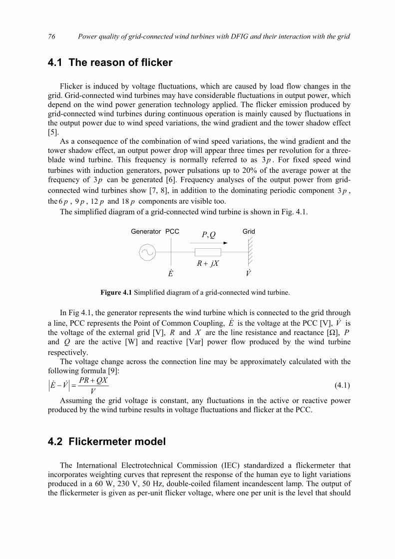
Power quality of grid-connected wind turbines with DFIG and their interaction with the grid
76
4.1 The reason of flicker Flicker is induced by voltage fluctuations, which are caused by load flow changes in the
grid. Grid-connected wind turbines may have considerable fluctuations in output power, which depend on the wind power generation technology applied. The flicker emission produced by grid-connected wind turbines during continuous operation is mainly caused by fluctuations in the output power due to wind speed variations, the wind gradient and the tower shadow effect [5].
As a consequence of the combination of wind speed variations, the wind gradient and the tower shadow effect, an output power drop will appear three times per revolution for a three-blade wind turbine. This frequency is normally referred to as p3 . For fixed speed wind turbines with induction generators, power pulsations up to 20% of the average power at the frequency of p3 can be generated [6]. Frequency analyses of the output power from grid-connected wind turbines show [7, 8], in addition to the dominating periodic component p3 , the p6 , p9 , p12 and p18 components are visible too.
The simplified diagram of a grid-connected wind turbine is shown in Fig. 4.1. In Fig 4.1, the generator represents the wind turbine which is connected to the grid through
a line, PCC represents the Point of Common Coupling, E& is the voltage at the PCC [V], V& is the voltage of the external grid [V], R and X are the line resistance and reactance [Ω], P and Q are the active [W] and reactive [Var] power flow produced by the wind turbine respectively.
The voltage change across the connection line may be approximately calculated with the following formula [9]:
VQXPRVE +
=− && (4.1)
Assuming the grid voltage is constant, any fluctuations in the active or reactive power produced by the wind turbine results in voltage fluctuations and flicker at the PCC.
4.2 Flickermeter model The International Electrotechnical Commission (IEC) standardized a flickermeter that
incorporates weighting curves that represent the response of the human eye to light variations produced in a 60 W, 230 V, 50 Hz, double-coiled filament incandescent lamp. The output of the flickermeter is given as per-unit flicker voltage, where one per unit is the level that should
QP,
V&E&jXR +
Generator GridPCC
Figure 4.1 Simplified diagram of a grid-connected wind turbine.

Chapter 4. Flicker emission of grid-connected wind turbines with DFIG
77
cause noticeable and annoying light flicker, with the perception threshold for 50% of the human population. On the basis of the output of flickermeter, a method is provided for the evaluation of short-term flicker severity, which is normally measured over a ten-minute period [4].
According to the IEC standard IEC 61000-4-15, a flickermeter model is developed to calculate the short-term flicker severity stP . The flickermeter architecture is described by the block diagram in Fig. 4.2, and can be divided into two parts, each performing one of the following tasks:
1. voltage adaptation and simulation of the response of the lamp-eye-brain chain
2. on-line statistical analysis of the flicker signal and presentation of the results
Blocks 1, 2, 3, 4 in Fig. 4.2 perform the first task, while the second task is accomplished
by block 5. “Block 1” scales the input voltage down to an internal reference level. In this way flicker
measurement can be made independently of the actual input carrier voltage. “Block 2” recovers the voltage fluctuation by squaring the input voltage scaled to the
reference level, thus simulating the behavior of a lamp. This block gives as a component of its output a voltage linearly related to the amplitude of the fluctuation modulating the input.
“Block 3” is composed of a cascade of two filters. The first filter eliminates the DC and double mains frequency ripple component of the demodulator (“Block 2”) output (the amplitude of higher frequency components is negligible). The filter incorporates a first order high-pass (suggested 3 dB cut-off frequency at about 0.05 Hz) and a low-pass section, for which a 6th order Butterworth filter with a 35 Hz 3 dB cut-off frequency is applied.
The second filter is a weighting filter that simulates the frequency response to sinusoidal voltage fluctuations of a coiled filament gas-filled lamp (60W, 230V) combined with the human visual system. The response function is based on the perceptibility threshold found at each frequency by 50% of the persons tested. This filter gives a band-pass response centered at 8.8 Hz, providing a very specific weighting function within the frequency band of interest (0.05 – 30 Hz). A suitable transfer function for the weighting filter, assuming that the carrier suppression filter defined above has negligible influence inside the frequency bandwidth associated to voltage fluctuation signals, is of the following type:
)/1)(/1(/1
2)(
43
221
21
ωωω
ωλω
sss
sssksF
+++
×++
= (4.2)
where s is the Laplace complex variable. Indicative values for the parameters are:
Inputvoltageadaptor
Squaringdemodulator
Squaringmultiplier,1th order
filter
On-linestatisticanalysis
Block 1 Block 5Block 4Block 3Block 2
u(t)
S(t)
stP
Figure 4.2 Block diagram of a flickermeter model.
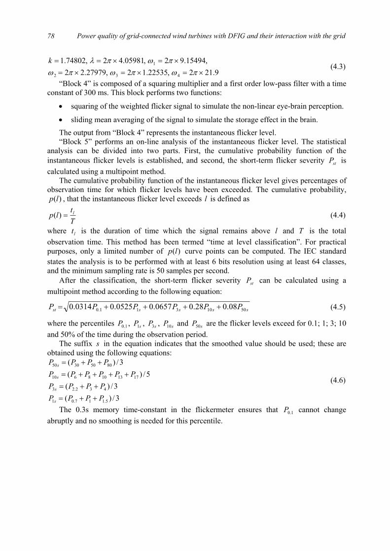
Power quality of grid-connected wind turbines with DFIG and their interaction with the grid
78
9.212,22535.12,27979.22,15494.92,05981.42,74802.1
432
1
×=×=×=×=×==
πωπωπωπωπλk
(4.3)
“Block 4” is composed of a squaring multiplier and a first order low-pass filter with a time constant of 300 ms. This block performs two functions:
• squaring of the weighted flicker signal to simulate the non-linear eye-brain perception.
• sliding mean averaging of the signal to simulate the storage effect in the brain.
The output from “Block 4” represents the instantaneous flicker level. “Block 5” performs an on-line analysis of the instantaneous flicker level. The statistical
analysis can be divided into two parts. First, the cumulative probability function of the instantaneous flicker levels is established, and second, the short-term flicker severity stP is calculated using a multipoint method.
The cumulative probability function of the instantaneous flicker level gives percentages of observation time for which flicker levels have been exceeded. The cumulative probability,
)(lp , that the instantaneous flicker level exceeds l is defined as
Tt
lp l=)( (4.4)
where lt is the duration of time which the signal remains above l and T is the total observation time. This method has been termed “time at level classification”. For practical purposes, only a limited number of )(lp curve points can be computed. The IEC standard states the analysis is to be performed with at least 6 bits resolution using at least 64 classes, and the minimum sampling rate is 50 samples per second.
After the classification, the short-term flicker severity stP can be calculated using a multipoint method according to the following equation:
ssssst PPPPPP 5010311.0 08.028.00657.00525.00314.0 ++++= (4.5)
where the percentiles 1.0P , sP1 , sP3 , sP10 and sP50 are the flicker levels exceed for 0.1; 1; 3; 10 and 50% of the time during the observation period.
The suffix s in the equation indicates that the smoothed value should be used; these are obtained using the following equations:
3/)(3/)(
5/)(3/)(
5.117.01
432.23
1713108610
80503050
PPPPPPPP
PPPPPPPPPP
s
s
s
s
++=++=
++++=++=
(4.6)
The 0.3s memory time-constant in the flickermeter ensures that 1.0P cannot change abruptly and no smoothing is needed for this percentile.

Chapter 4. Flicker emission of grid-connected wind turbines with DFIG
79
4.3 Flicker emission of grid-connected wind turbines with DFIG
This section is concentrated on flicker emission of grid-connected wind turbines with
DFIG during continuous operation. The system studied here is shown in Fig. 4.3. It represents a typical situation, where a wind farm with DFIG represented by a single machine is integrated to the external power system represented by a constant voltage source connected in series with its Thevenin’s equivalent impedance. Bus 2 accounts for the PCC, where the short-term flicker severity is the study interest. The external power system is connected to bus 2 through a line 1-2, where the impedance magnitude is 0.7562 Ω . The magnitude of the Thevenin’s equivalent impedance can be found out by the rated voltage and the short circuit capacity.
The wind turbine has a 2 MW DFIG connected with a back-to-back PWM voltage source
converter in the rotor circuit. The parameters of the generator are as shown in Table 3.1. The wind turbine generates 2 MW active power during rated state operation, while the output reactive power of the wind turbine is normally controlled as zero in order to keep unity power factor.
The short-term flicker severity of bus 2, the PCC, is calculated on the basis of the voltage fluctuation. A base case with the parameters given in Table 4.1 is first considered, where the turbulence intensity, short circuit capacity ratio, grid impedance angle are defined as:
)arctan( RXSSSCR
vvIn
k
nk
==∆=
ψ (4.7)
where v∆ is the wind speed standard deviation, v is the mean wind speed, kS is the short circuit apparent power of the grid where the wind turbines are connected, nS is the rated apparent power of the wind turbines, R and X are the resistance and reactance of the grid line.
The wind applied in this investigation is produced according to the wind model introduced in Chapter 2. Since only one wind turbine is considered in this case, the park scale wind model is not included and only the rotor wind speed is applied. The wind speed and the output power of the wind turbine in the base case are shown in Fig. 4.4.
3-bladeturbine
GearboxTransformer
2.5MVA
GlZl=0.7562 Zth
Eth=11kV2 1
Wind
DFIG
Capacitor
PWMconverter
PWMconverter Wind
turbine
PCC
Figure 4.3 Block diagram of the studied system for flicker emission.
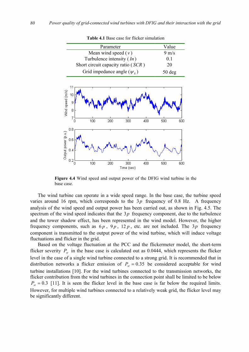
Power quality of grid-connected wind turbines with DFIG and their interaction with the grid
80
Table 4.1 Base case for flicker simulation
Parameter Value Mean wind speed ( v ) 9 m/s
Turbulence intensity ( In ) 0.1 Short circuit capacity ratio ( SCR ) 20
Grid impedance angle ( kψ ) 50 deg The wind turbine can operate in a wide speed range. In the base case, the turbine speed
varies around 16 rpm, which corresponds to the p3 frequency of 0.8 Hz. A frequency analysis of the wind speed and output power has been carried out, as shown in Fig. 4.5. The spectrum of the wind speed indicates that the p3 frequency component, due to the turbulence and the tower shadow effect, has been represented in the wind model. However, the higher frequency components, such as p6 , p9 , p12 , etc. are not included. The p3 frequency component is transmitted to the output power of the wind turbine, which will induce voltage fluctuations and flicker in the grid.
Based on the voltage fluctuation at the PCC and the flickermeter model, the short-term flicker severity stP in the base case is calculated out as 0.0444, which represents the flicker level in the case of a single wind turbine connected to a strong grid. It is recommended that in distribution networks a flicker emission of 35.0=stP be considered acceptable for wind turbine installations [10]. For the wind turbines connected to the transmission networks, the flicker contribution from the wind turbines in the connection point shall be limited to be below
3.0=stP [11]. It is seen the flicker level in the base case is far below the required limits. However, for multiple wind turbines connected to a relatively weak grid, the flicker level may be significantly different.
Figure 4.4 Wind speed and output power of the DFIG wind turbine in thebase case.
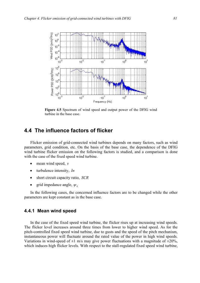
Chapter 4. Flicker emission of grid-connected wind turbines with DFIG
81
4.4 The influence factors of flicker
Flicker emission of grid-connected wind turbines depends on many factors, such as wind
parameters, grid condition, etc. On the basis of the base case, the dependence of the DFIG wind turbine flicker emission on the following factors is studied, and a comparison is done with the case of the fixed speed wind turbine.
• mean wind speed, v
• turbulence intensity, In
• short circuit capacity ratio, SCR
• grid impedance angle, kψ
In the following cases, the concerned influence factors are to be changed while the other parameters are kept constant as in the base case.
4.4.1 Mean wind speed
In the case of the fixed speed wind turbine, the flicker rises up at increasing wind speeds.
The flicker level increases around three times from lower to higher wind speed. As for the pitch-controlled fixed speed wind turbine, due to gusts and the speed of the pitch mechanism, instantaneous power will fluctuate around the rated value of the power in high wind speeds. Variations in wind-speed of ±1 m/s may give power fluctuations with a magnitude of ±20%, which induces high flicker levels. With respect to the stall-regulated fixed speed wind turbine,
Figure 4.5 Spectrum of wind speed and output power of the DFIG windturbine in the base case.
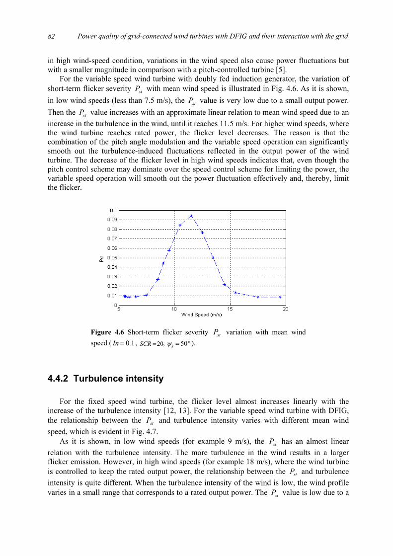
Power quality of grid-connected wind turbines with DFIG and their interaction with the grid
82
in high wind-speed condition, variations in the wind speed also cause power fluctuations but with a smaller magnitude in comparison with a pitch-controlled turbine [5].
For the variable speed wind turbine with doubly fed induction generator, the variation of short-term flicker severity stP with mean wind speed is illustrated in Fig. 4.6. As it is shown, in low wind speeds (less than 7.5 m/s), the stP value is very low due to a small output power. Then the stP value increases with an approximate linear relation to mean wind speed due to an increase in the turbulence in the wind, until it reaches 11.5 m/s. For higher wind speeds, where the wind turbine reaches rated power, the flicker level decreases. The reason is that the combination of the pitch angle modulation and the variable speed operation can significantly smooth out the turbulence-induced fluctuations reflected in the output power of the wind turbine. The decrease of the flicker level in high wind speeds indicates that, even though the pitch control scheme may dominate over the speed control scheme for limiting the power, the variable speed operation will smooth out the power fluctuation effectively and, thereby, limit the flicker.
4.4.2 Turbulence intensity
For the fixed speed wind turbine, the flicker level almost increases linearly with the
increase of the turbulence intensity [12, 13]. For the variable speed wind turbine with DFIG, the relationship between the stP and turbulence intensity varies with different mean wind speed, which is evident in Fig. 4.7.
As it is shown, in low wind speeds (for example 9 m/s), the stP has an almost linear relation with the turbulence intensity. The more turbulence in the wind results in a larger flicker emission. However, in high wind speeds (for example 18 m/s), where the wind turbine is controlled to keep the rated output power, the relationship between the stP and turbulence intensity is quite different. When the turbulence intensity of the wind is low, the wind profile varies in a small range that corresponds to a rated output power. The stP value is low due to a
Figure 4.6 Short-term flicker severity stP variation with mean windspeed ( 1.0=In , 20=SCR , °= 50kψ ).
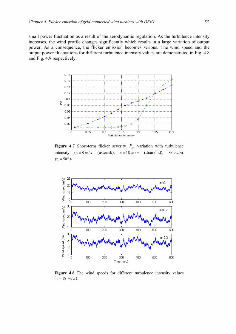
Chapter 4. Flicker emission of grid-connected wind turbines with DFIG
83
small power fluctuation as a result of the aerodynamic regulation. As the turbulence intensity increases, the wind profile changes significantly which results in a large variation of output power. As a consequence, the flicker emission becomes serious. The wind speed and the output power fluctuations for different turbulence intensity values are demonstrated in Fig. 4.8 and Fig. 4.9 respectively.
Figure 4.7 Short-term flicker severity stP variation with turbulenceintensity ( smv /9= (asterisk), smv /18= (diamond), 20=SCR ,
°= 50kψ ).
Figure 4.8 The wind speeds for different turbulence intensity values( smv /18= ).
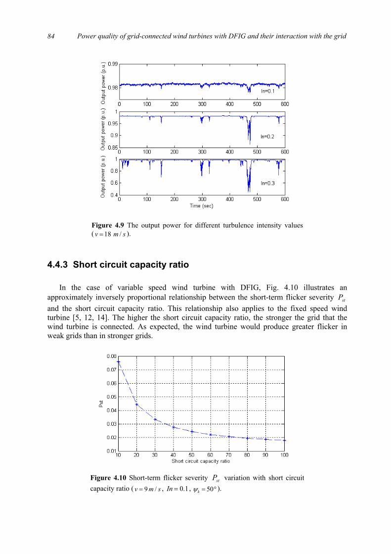
Power quality of grid-connected wind turbines with DFIG and their interaction with the grid
84
4.4.3 Short circuit capacity ratio
In the case of variable speed wind turbine with DFIG, Fig. 4.10 illustrates an
approximately inversely proportional relationship between the short-term flicker severity stP and the short circuit capacity ratio. This relationship also applies to the fixed speed wind turbine [5, 12, 14]. The higher the short circuit capacity ratio, the stronger the grid that the wind turbine is connected. As expected, the wind turbine would produce greater flicker in weak grids than in stronger grids.
Figure 4.9 The output power for different turbulence intensity values( smv /18= ).
Figure 4.10 Short-term flicker severity stP variation with short circuitcapacity ratio ( smv /9= , 1.0=In , °= 50kψ ).
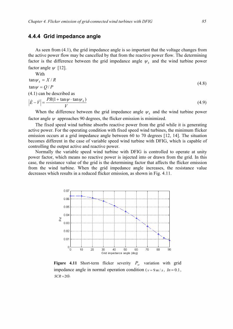
Chapter 4. Flicker emission of grid-connected wind turbines with DFIG
85
4.4.4 Grid impedance angle
As seen from (4.1), the grid impedance angle is so important that the voltage changes from
the active power flow may be cancelled by that from the reactive power flow. The determining factor is the difference between the grid impedance angle kψ and the wind turbine power factor angle ψ [12].
With
PQRXk
/tan/tan
==
ψψ
(4.8)
(4.1) can be described as
VPR
VE k )tantan1( ψψ ⋅+=− && (4.9)
When the difference between the grid impedance angle kψ and the wind turbine power factor angle ψ approaches 90 degrees, the flicker emission is minimized.
The fixed speed wind turbine absorbs reactive power from the grid while it is generating active power. For the operating condition with fixed speed wind turbines, the minimum flicker emission occurs at a grid impedance angle between 60 to 70 degrees [12, 14]. The situation becomes different in the case of variable speed wind turbine with DFIG, which is capable of controlling the output active and reactive power.
Normally the variable speed wind turbine with DFIG is controlled to operate at unity power factor, which means no reactive power is injected into or drawn from the grid. In this case, the resistance value of the grid is the determining factor that affects the flicker emission from the wind turbine. When the grid impedance angle increases, the resistance value decreases which results in a reduced flicker emission, as shown in Fig. 4.11.
Figure 4.11 Short-term flicker severity stP variation with gridimpedance angle in normal operation condition ( smv /9= , 1.0=In ,
20=SCR ).
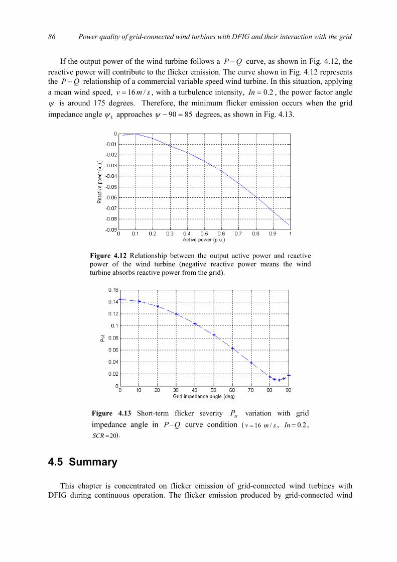
Power quality of grid-connected wind turbines with DFIG and their interaction with the grid
86
If the output power of the wind turbine follows a QP − curve, as shown in Fig. 4.12, the reactive power will contribute to the flicker emission. The curve shown in Fig. 4.12 represents the QP − relationship of a commercial variable speed wind turbine. In this situation, applying a mean wind speed, smv /16= , with a turbulence intensity, 2.0=In , the power factor angle ψ is around 175 degrees. Therefore, the minimum flicker emission occurs when the grid impedance angle kψ approaches 8590 =−ψ degrees, as shown in Fig. 4.13.
4.5 Summary
This chapter is concentrated on flicker emission of grid-connected wind turbines with
DFIG during continuous operation. The flicker emission produced by grid-connected wind
Figure 4.12 Relationship between the output active power and reactivepower of the wind turbine (negative reactive power means the windturbine absorbs reactive power from the grid).
Figure 4.13 Short-term flicker severity stP variation with gridimpedance angle in QP− curve condition ( smv /16= , 2.0=In ,
20=SCR ).

Chapter 4. Flicker emission of grid-connected wind turbines with DFIG
87
turbines during continuous operation is mainly caused by fluctuations in the output power due to wind speed variations, the wind gradient and the tower shadow effect. To evaluate the flicker levels produced by grid-connected wind turbines with DFIG, a flickermeter model is developed according to the IEC standard IEC 61000-4-15. The flickermeter simulates the response of the lamp-eye-brain chain and presents the short-term flicker severity stP using on-line statistical analysis.
Based on the developed wind turbine model and the flickermeter model, flicker emission of grid-connected wind turbines with DFIG is investigated during continuous operation. Simulation results show that the wind characteristics (mean speed, turbulence intensity) and the grid conditions (short circuit capacity, grid impedance angle) have significant effects on the flicker emission of the variable speed wind turbine with DFIG.
In low wind speeds, the stP value is very low due to a small output power. Then the stP value increases with an approximate linear relation to mean wind speed due to an increase in the turbulence in the wind. For higher wind speeds, where the wind turbine reaches rated power, the pitch angle modulation and variable speed operation smooth out significantly the turbulence-induced fluctuations reflected in the output power of the wind turbine, which results in the reduced flicker levels.
In low wind speeds, the stP has an almost linear relation with the turbulence intensity. However, in high wind speeds, the relationship between the stP and turbulence intensity is quite different. When the turbulence intensity of the wind is low, the wind profile varies in a small range that corresponds to a rated output power. The stP value is low due to a small power fluctuation as a result of the aerodynamic regulation. As the turbulence intensity increases, the wind profile changes significantly which results in a large variation of output power. As a consequence, the flicker emission becomes serious.
There exists an approximately inversely proportional relationship between the stP and the short circuit capacity ratio.
The grid impedance angle kψ has an significant influence on flicker emission of grid-connected wind turbines with DFIG. When the difference between the grid impedance angle
kψ and the wind turbine power factor angle ψ approaches 90 degrees, the flicker emission is minimized.
The effects of the influence factors are compared with previous research results related to the fixed speed wind turbine. In particular, the effects of mean wind speed, turbulence intensity and grid impedance angle are different from that in the case of the fixed speed wind turbine.
Bibliography
[1] International Electrotechnical Commission, Wind turbine generator systems --- Part 21: measurement and assessment of power quality characteristics of grid connected wind turbines, IEC 61400-21, International Electrotechnical Commission, Geneva, Switzerland, Dec. 2001.

Power quality of grid-connected wind turbines with DFIG and their interaction with the grid
88
[2] L. Rossetto, P. Tenti, A. Zuccato, “Electromagnetic compatibility issues in industrial equipment,” IEEE Industry Application Magazine, vol. 5, Issue. 6, pp. 34-46, Nov./Dec. 1999.
[3] F. Blaabjerg, Z. Chen, “Power electronics as an enabling technology for renewable energy integration,” Journal of Power Electronics, vol. 3, no. 2, pp. 81-89, Apr. 2003.
[4] International Electrotechnical Commission, Electromagnetic Compatibility (EMC) --- Part 4: Testing and measurement techniques --- Section 15: Flickermeter --- Functional and design specifications, IEC 61000-4-15, International Electrotechnical Commission, Geneva, Switzerland, Nov. 1997.
[5] Åke Larsson, “Flicker emission of wind turbines during continuous operation,” IEEE Trans. on Energy Conversion, vol. 17, no. 1, pp. 114-118, Mar. 2002.
[6] G. Gerdes, F. Santjer, “Power quality of wind turbines and their interaction with the grid,” Proc. of Euro. Wind Energy Conf., pp. 1112-1115, Oct. 1994.
[7] T. Thiringer, J. Dahlberg, “Periodic pulsations from a three-bladed wind turbine,” IEEE Trans. on Energy Conversion, vol. 16, no. 2, pp. 128-133, June 2001.
[8] T. Thiringer, “Power quality measurements performed on a low-voltage grid equipped with two wind turbines,” IEEE Trans. on Energy Conversion, vol. 11, no. 3, pp. 601-606, Sep. 1996.
[9] T. Burton, D. Sharpe, N. Jenkins, E. Bossanyi, Wind energy handbook, John Wiley & Sons Ltd, Chichester, 2001.
[10] Research Institute for Danish Electric Utilities (DEFU), Connection of wind turbines to low and medium voltage networks, 2nd ed., DEFU KR-111, Research Institute for Danish Electric Utilities (DEFU), Oct. 1998.
[11] ELTRA Transmission System Planning, Specifications for connecting wind farms to the transmission network, 2nd ed., ELT1999-411a, ELTRA Transmission System Planning, Apr. 2000.
[12] M. P. Papadopoulos, S. A. Papathanassiou, S. T. Tentzerakis, N. G. Boulaxis, “Investigation of the flicker emission by grid connected wind turbines,” Proc. of the 8th International Conference on Harmonics And Quality of Power, vol. 2, pp. 1152-1157, Oct. 1998.
[13] P. D. Ladakakos, M. G. Ioannides, M. I. Koulouvari, “Assessment of wind turbines impact on the power quality of autonomous weak grids,” Proc. of the 8th International Conference on Harmonics and Quality of Power, vol. 2, pp. 900-905, Oct. 1998.
[14] H. Amarís, C. Vilar, J. Usaola, J. L. Rodríguez, “Frequency domain analysis of flicker produced by wind energy conversions systems,” Proc. of the 8th International Conference on Harmonics and Quality of Power, vol. 2, pp. 1162-1167, Oct. 1998.
89
Chapter 5
Flicker mitigation of grid-connected wind turbines with DFIG
Even though variable speed wind turbines have good performance with respect to flicker emission, flicker mitigation becomes necessary as the wind power penetration level increases. As described in Chapter 4, flicker is mainly induced by voltage fluctuations caused by the variation in the output power of grid-connected wind turbines. Any fluctuations in the active or reactive power produced by grid-connected wind turbines results in voltage fluctuations and flicker at the coupling point of the wind turbines.
It is possible to regulate the reactive power flow on the connection line, thus the voltage fluctuation caused by the active power flow can be compensated by that caused by the reactive power flow. Grid-connected wind turbines with DFIG are capable of controlling the output active and reactive power independently, which makes it possible that the reactive power flow on the connection line can be regulated by controlling the wind turbines output power. Regulating the reactive power flow on the connection line can also be realized by using reactive power compensation devices, such as STATCOM.
This chapter focuses on flicker mitigation of grid-connected wind turbines with DFIG during continuous operation, which is realized by controlling the wind turbines output reactive power and using STATCOM. First, the principle of flicker mitigation of grid-connected wind turbines is analysed. Next, the output reactive power control of the wind turbine is applied to mitigate the flicker levels. Finally, flicker mitigation is realized by using STATCOM. The model and control scheme of the STATCOM are described and validated by simulations.
5.1 The principle Considering the system illustrated in Fig. 4.1, (4.9) may be rewritten as follows:
k
k
k
VPR
VPR
VE
ψψψψ
ψψ
coscos)cos(
)tantan1(
⋅⋅−⋅
=
⋅+=− &&
(5.1)
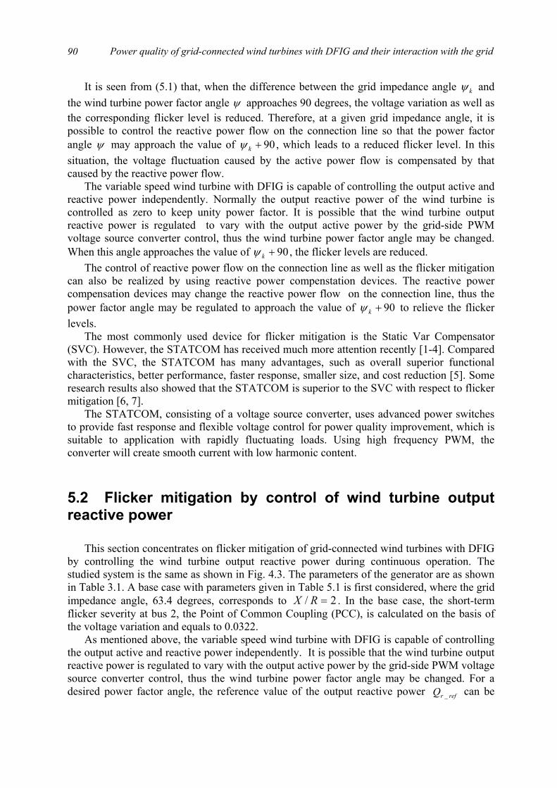
Power quality of grid-connected wind turbines with DFIG and their interaction with the grid
90
It is seen from (5.1) that, when the difference between the grid impedance angle kψ and the wind turbine power factor angle ψ approaches 90 degrees, the voltage variation as well as the corresponding flicker level is reduced. Therefore, at a given grid impedance angle, it is possible to control the reactive power flow on the connection line so that the power factor angle ψ may approach the value of 90+kψ , which leads to a reduced flicker level. In this situation, the voltage fluctuation caused by the active power flow is compensated by that caused by the reactive power flow.
The variable speed wind turbine with DFIG is capable of controlling the output active and reactive power independently. Normally the output reactive power of the wind turbine is controlled as zero to keep unity power factor. It is possible that the wind turbine output reactive power is regulated to vary with the output active power by the grid-side PWM voltage source converter control, thus the wind turbine power factor angle may be changed. When this angle approaches the value of 90+kψ , the flicker levels are reduced.
The control of reactive power flow on the connection line as well as the flicker mitigation can also be realized by using reactive power compenstation devices. The reactive power compensation devices may change the reactive power flow on the connection line, thus the power factor angle may be regulated to approach the value of 90+kψ to relieve the flicker levels.
The most commonly used device for flicker mitigation is the Static Var Compensator (SVC). However, the STATCOM has received much more attention recently [1-4]. Compared with the SVC, the STATCOM has many advantages, such as overall superior functional characteristics, better performance, faster response, smaller size, and cost reduction [5]. Some research results also showed that the STATCOM is superior to the SVC with respect to flicker mitigation [6, 7].
The STATCOM, consisting of a voltage source converter, uses advanced power switches to provide fast response and flexible voltage control for power quality improvement, which is suitable to application with rapidly fluctuating loads. Using high frequency PWM, the converter will create smooth current with low harmonic content.
5.2 Flicker mitigation by control of wind turbine output reactive power
This section concentrates on flicker mitigation of grid-connected wind turbines with DFIG
by controlling the wind turbine output reactive power during continuous operation. The studied system is the same as shown in Fig. 4.3. The parameters of the generator are as shown in Table 3.1. A base case with parameters given in Table 5.1 is first considered, where the grid impedance angle, 63.4 degrees, corresponds to 2/ =RX . In the base case, the short-term flicker severity at bus 2, the Point of Common Coupling (PCC), is calculated on the basis of the voltage variation and equals to 0.0322.
As mentioned above, the variable speed wind turbine with DFIG is capable of controlling the output active and reactive power independently. It is possible that the wind turbine output reactive power is regulated to vary with the output active power by the grid-side PWM voltage source converter control, thus the wind turbine power factor angle may be changed. For a desired power factor angle, the reference value of the output reactive power refrQ _ can be
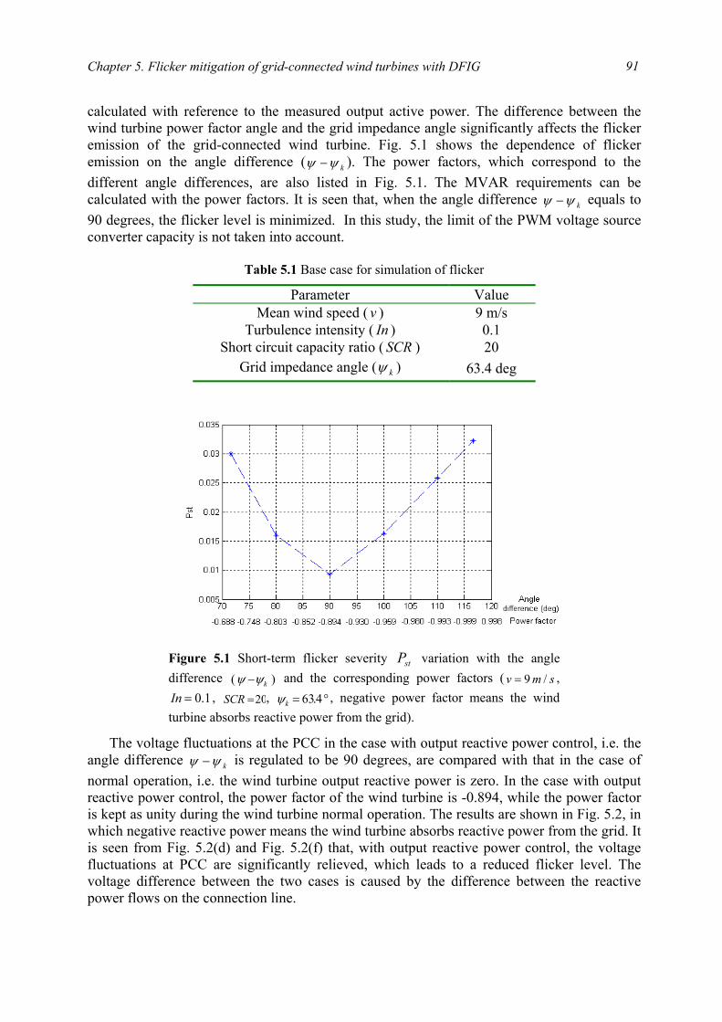
Chapter 5. Flicker mitigation of grid-connected wind turbines with DFIG
91
calculated with reference to the measured output active power. The difference between the wind turbine power factor angle and the grid impedance angle significantly affects the flicker emission of the grid-connected wind turbine. Fig. 5.1 shows the dependence of flicker emission on the angle difference ( kψψ − ). The power factors, which correspond to the different angle differences, are also listed in Fig. 5.1. The MVAR requirements can be calculated with the power factors. It is seen that, when the angle difference kψψ − equals to 90 degrees, the flicker level is minimized. In this study, the limit of the PWM voltage source converter capacity is not taken into account.
Table 5.1 Base case for simulation of flicker
Parameter Value Mean wind speed ( v ) 9 m/s
Turbulence intensity ( In ) 0.1 Short circuit capacity ratio ( SCR ) 20
Grid impedance angle ( kψ ) 63.4 deg The voltage fluctuations at the PCC in the case with output reactive power control, i.e. the
angle difference kψψ − is regulated to be 90 degrees, are compared with that in the case of normal operation, i.e. the wind turbine output reactive power is zero. In the case with output reactive power control, the power factor of the wind turbine is -0.894, while the power factor is kept as unity during the wind turbine normal operation. The results are shown in Fig. 5.2, in which negative reactive power means the wind turbine absorbs reactive power from the grid. It is seen from Fig. 5.2(d) and Fig. 5.2(f) that, with output reactive power control, the voltage fluctuations at PCC are significantly relieved, which leads to a reduced flicker level. The voltage difference between the two cases is caused by the difference between the reactive power flows on the connection line.
Figure 5.1 Short-term flicker severity stP variation with the angledifference )( kψψ − and the corresponding power factors ( smv /9= ,
1.0=In , 20=SCR , °= 4.63kψ , negative power factor means the windturbine absorbs reactive power from the grid).
Power quality of grid-connected wind turbines with DFIG and their interaction with the grid
92
This law applies to other cases with different parameters. Fig. 5.3 – Fig. 5.6 illustrate the
flicker level differences between the case with output reactive power control and the case of normal operation, under different parameters, such as mean wind speed, turbulence intensity,
Figure 5.2 Comparison between the case with output reactive powercontrol and the case of normal operation ( smv /9= , 1.0=In , 20=SCR ,
°= 4.63kψ ). (a) Wind speed; (b) Wind turbine output active power; (c)Wind turbine output reactive power in the case of normal operation; (d)Voltage at the PCC in the case of normal operation; (e) Wind turbine output reactive power in the case with output reactive power control; (f)Voltage at the PCC in the case with output reactive power control.
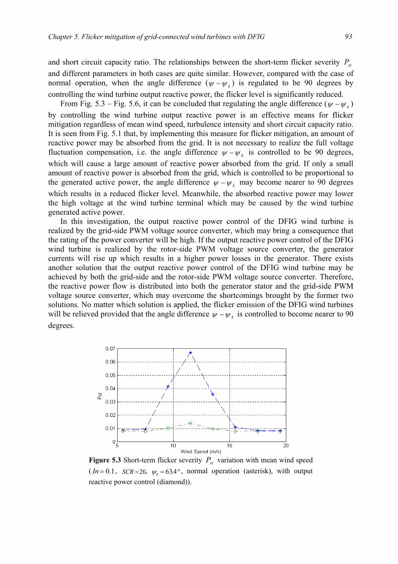
Chapter 5. Flicker mitigation of grid-connected wind turbines with DFIG
93
and short circuit capacity ratio. The relationships between the short-term flicker severity stP and different parameters in both cases are quite similar. However, compared with the case of normal operation, when the angle difference ( kψψ − ) is regulated to be 90 degrees by controlling the wind turbine output reactive power, the flicker level is significantly reduced.
From Fig. 5.3 – Fig. 5.6, it can be concluded that regulating the angle difference ( kψψ − ) by controlling the wind turbine output reactive power is an effective means for flicker mitigation regardless of mean wind speed, turbulence intensity and short circuit capacity ratio. It is seen from Fig. 5.1 that, by implementing this measure for flicker mitigation, an amount of reactive power may be absorbed from the grid. It is not necessary to realize the full voltage fluctuation compensation, i.e. the angle difference kψψ − is controlled to be 90 degrees, which will cause a large amount of reactive power absorbed from the grid. If only a small amount of reactive power is absorbed from the grid, which is controlled to be proportional to the generated active power, the angle difference kψψ − may become nearer to 90 degrees which results in a reduced flicker level. Meanwhile, the absorbed reactive power may lower the high voltage at the wind turbine terminal which may be caused by the wind turbine generated active power.
In this investigation, the output reactive power control of the DFIG wind turbine is realized by the grid-side PWM voltage source converter, which may bring a consequence that the rating of the power converter will be high. If the output reactive power control of the DFIG wind turbine is realized by the rotor-side PWM voltage source converter, the generator currents will rise up which results in a higher power losses in the generator. There exists another solution that the output reactive power control of the DFIG wind turbine may be achieved by both the grid-side and the rotor-side PWM voltage source converter. Therefore, the reactive power flow is distributed into both the generator stator and the grid-side PWM voltage source converter, which may overcome the shortcomings brought by the former two solutions. No matter which solution is applied, the flicker emission of the DFIG wind turbines will be relieved provided that the angle difference kψψ − is controlled to become nearer to 90 degrees.
Figure 5.3 Short-term flicker severity stP variation with mean wind speed( 1.0=In , 20=SCR , °= 4.63kψ , normal operation (asterisk), with outputreactive power control (diamond)).
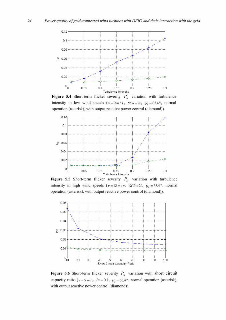
Power quality of grid-connected wind turbines with DFIG and their interaction with the grid
94
Figure 5.4 Short-term flicker severity stP variation with turbulenceintensity in low wind speeds ( smv /9= , 20=SCR , °= 4.63kψ , normaloperation (asterisk), with output reactive power control (diamond)).
Figure 5.5 Short-term flicker severity stP variation with turbulenceintensity in high wind speeds ( smv /18= , 20=SCR , °= 4.63kψ , normaloperation (asterisk), with output reactive power control (diamond)).
Figure 5.6 Short-term flicker severity stP variation with short circuit capacity ratio ( smv /9= , 1.0=In , °= 4.63kψ , normal operation (asterisk), with output reactive power control (diamond)).
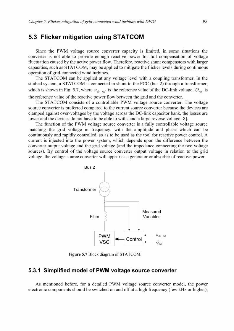
Chapter 5. Flicker mitigation of grid-connected wind turbines with DFIG
95
5.3 Flicker mitigation using STATCOM
Since the PWM voltage source converter capacity is limited, in some situations the
converter is not able to provide enough reactive power for full compensation of voltage fluctuation caused by the active power flow. Therefore, reactive shunt compenstors with larger capacities, such as STATCOM, may be applied to mitigate the flicker levels during continuous operation of grid-connected wind turbines.
The STATCOM can be applied at any voltage level with a coupling transformer. In the studied system, a STATCOM is connected in shunt to the PCC (bus 2) through a transformer, which is shown in Fig. 5.7, where refdcu _ is the reference value of the DC-link voltage, refQ is the reference value of the reactive power flow between the grid and the converter.
The STATCOM consists of a controllable PWM voltage source converter. The voltage source converter is preferred compared to the current source converter because the devices are clamped against over-voltages by the voltage across the DC-link capacitor bank, the losses are lower and the devices do not have to be able to withstand a large reverse voltage [8].
The function of the PWM voltage source converter is a fully controllable voltage source matching the grid voltage in frequency, with the amplitude and phase which can be continuously and rapidly controlled, so as to be used as the tool for reactive power control. A current is injected into the power system, which depends upon the difference between the converter output voltage and the grid voltage (and the impedance connecting the two voltage sources). By control of the voltage source converter output voltage in relation to the grid voltage, the voltage source converter will appear as a generator or absorber of reactive power.
5.3.1 Simplified model of PWM voltage source converter
As mentioned before, for a detailed PWM voltage source converter model, the power
electronic components should be switched on and off at a high frequency (few kHz or higher),
PWMVSC Control
Bus 2
MeasuredVariables
Transformer
Filter
refQrefdcu _
Figure 5.7 Block diagram of STATCOM.
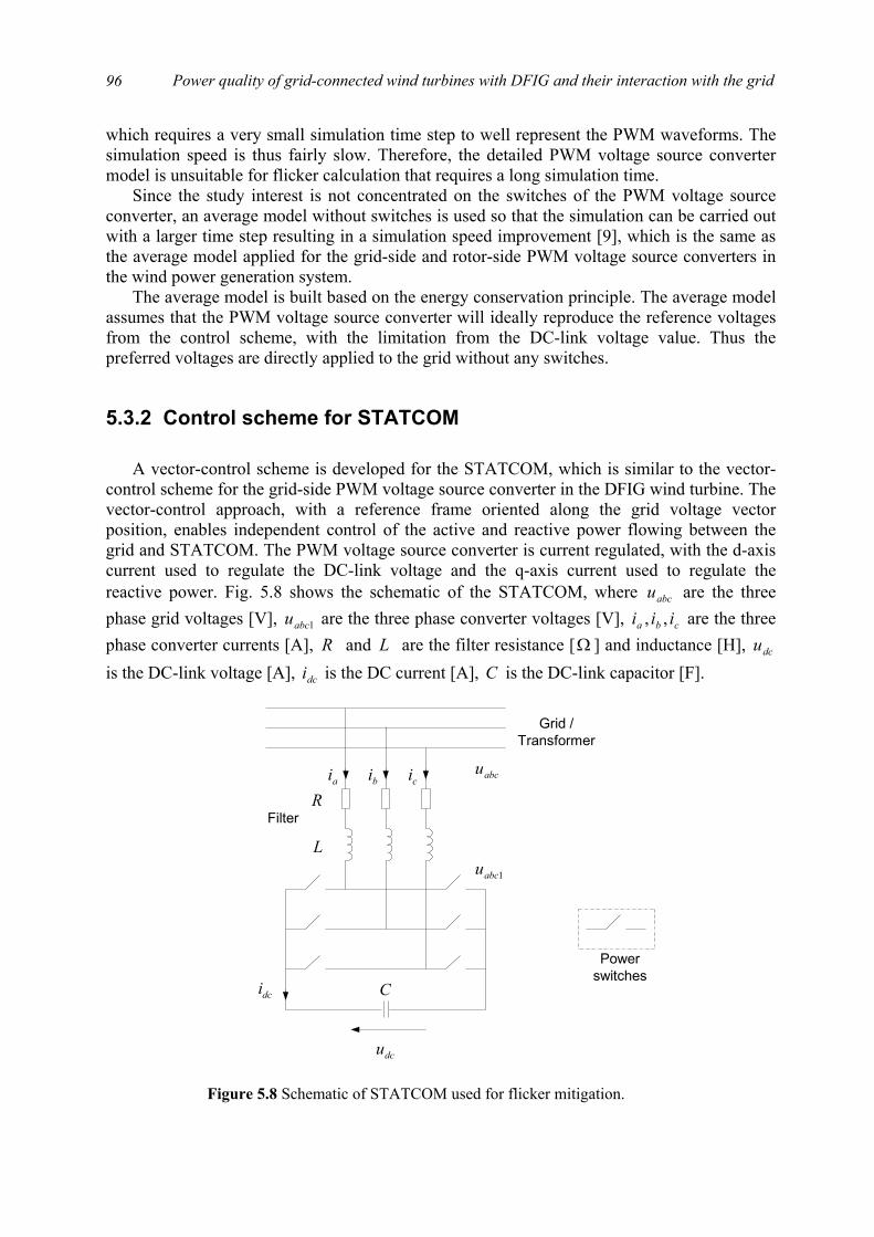
Power quality of grid-connected wind turbines with DFIG and their interaction with the grid
96
which requires a very small simulation time step to well represent the PWM waveforms. The simulation speed is thus fairly slow. Therefore, the detailed PWM voltage source converter model is unsuitable for flicker calculation that requires a long simulation time.
Since the study interest is not concentrated on the switches of the PWM voltage source converter, an average model without switches is used so that the simulation can be carried out with a larger time step resulting in a simulation speed improvement [9], which is the same as the average model applied for the grid-side and rotor-side PWM voltage source converters in the wind power generation system.
The average model is built based on the energy conservation principle. The average model assumes that the PWM voltage source converter will ideally reproduce the reference voltages from the control scheme, with the limitation from the DC-link voltage value. Thus the preferred voltages are directly applied to the grid without any switches.
5.3.2 Control scheme for STATCOM
A vector-control scheme is developed for the STATCOM, which is similar to the vector-
control scheme for the grid-side PWM voltage source converter in the DFIG wind turbine. The vector-control approach, with a reference frame oriented along the grid voltage vector position, enables independent control of the active and reactive power flowing between the grid and STATCOM. The PWM voltage source converter is current regulated, with the d-axis current used to regulate the DC-link voltage and the q-axis current used to regulate the reactive power. Fig. 5.8 shows the schematic of the STATCOM, where abcu are the three phase grid voltages [V], 1abcu are the three phase converter voltages [V], cba iii ,, are the three phase converter currents [A], R and L are the filter resistance [ Ω ] and inductance [H], dcu is the DC-link voltage [A], dci is the DC current [A], C is the DC-link capacitor [F].
dcu
dci
Grid /Transformer
L
Rai bi ci abcu
1abcu
Powerswitches
Filter
C
Figure 5.8 Schematic of STATCOM used for flicker mitigation.

Chapter 5. Flicker mitigation of grid-connected wind turbines with DFIG
97
The voltage balance across the filter is
+
+
=
1
1
1
c
b
a
c
b
a
c
b
a
c
b
a
uuu
iii
dtdL
iii
Ruuu
(5.2)
Using the abc-to-dq transformation matrix introduced before, the corresponding equation in a dq reference frame rotating at ew is
1
1
qdeq
dqed
dd
uLiwdtdi
LRiu
uLiwdtdi
LRiu
+++=
+−+= (5.3)
where qd uu , are the grid voltages [V] in d- and q-axis, 11 , qd uu are the converter voltages [V] in d- and q-axis, qd ii , are the converter currents [A] in d- and q-axis.
The active and reactive power flows between the grid and the converter are
)(23
)(23
qddq
qqdd
iuiuQ
iuiuP
−=
+= (5.4)
The angular position of the grid voltage is calculated as
α
βθuu
dtwee1tan−== ∫ (5.5)
where αu and βu are the stationary dq-axis grid voltage components [V]. Aligning the d-axis of the reference frame along the grid voltage position given by (5.5),
qu is zero, and du is constant because the amplitude of the grid voltage is assumed to be constant. Therefore, the active power and reactive power between the grid and the converter will be proportional to di and qi respectively
qd
dd
iuQ
iuP
23
23
−=
= (5.6)
Neglecting harmonics due to the switching and the losses in the resistance and the converter, following is valid
dcdc
ddc
dcd
dddcdc
idt
duC
mii
umu
iuiu
=
=
=
=
432
23
(5.7)
where m is the PWM modulation depth of the voltage source converter.
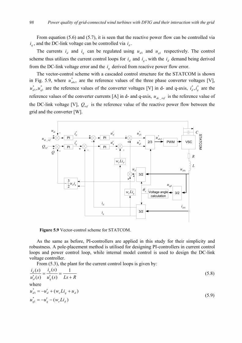
Power quality of grid-connected wind turbines with DFIG and their interaction with the grid
98
From equation (5.6) and (5.7), it is seen that the reactive power flow can be controlled via qi , and the DC-link voltage can be controlled via di .
The currents di and qi can be regulated using 1du and 1qu respectively. The control scheme thus utilizes the current control loops for di and qi , with the di demand being derived from the DC-link voltage error and the qi derived from reactive power flow error.
The vector-control scheme with a cascaded control structure for the STATCOM is shown in Fig. 5.9, where *
1abcu are the reference values of the three phase converter voltages [V], *1
*1 , qd uu are the reference values of the converter voltages [V] in d- and q-axis, ** , qd ii are the
reference values of the converter currents [A] in d- and q-axis, refdcu _ is the reference value of
the DC-link voltage [V], refQ is the reference value of the reactive power flow between the grid and the converter [W].
As the same as before, PI-controllers are applied in this study for their simplicity and
robustness. A pole-placement method is utilised for designing PI-controllers in current control loops and power control loop, while internal model control is used to design the DC-link voltage controller.
From (5.3), the plant for the current control loops is given by:
RLssusi
susi
q
q
d
d
+=
′=
′1
)()(
)()(
(5.8)
where
)(
)(*1
*1
deqq
dqedd
Liwuu
uLiwuu
−′−=
++′−= (5.9)
PWM2/3
3/2Voltage anglecalculation
3/2
3/2
PI
PI
qe Liw
de Liw
PIrefdcu _
dcu+
- *di +
-
du′
di
qi
*qi qu′
+ -
-
+
++
du
*1du
*1qu
- -
*1abcu
L
R
eθ
abcu
abci
αβu
PIrefQ
qdiu23
−
Q+
-
VSC
C STATCO
M
Figure 5.9 Vector-control scheme for STATCOM.
Chapter 5. Flicker mitigation of grid-connected wind turbines with DFIG
99
where
dtdi
LRiu
dtdi
LRiu
qqq
ddd
+=′
+=′ (5.10)
In (5.9) the terms in brackets constitute voltage-compensation terms. The effective transfer functions of the reactive power control loop can be derived from
(5.6) as:
dq
usisQ
23
)()(
−= (5.11)
The effective transfer function of the DC-link voltage control loop can be derived from (5.7):
Csm
sisu
d
dc
43
)()(
= (5.12)
The parameters of the filter in series with the STATCOM are: HLR 00083.0,0173.0 =Ω= . The value of the capacitor in the DC-link is set as:
FC 03.0= . The reference value of the DC-link voltage refdcu _ is set to 1200 V. Similar to the PI-controller design in Chapter 3, the pole-placement method is applied to
design the PI-controllers in the current control loops and the power control loop, while internal model control is employed to design the DC-link voltage controller.
The parameters of the PI-controllers in the current control loops may be obtained based on the plant shown in (5.8) and the pole-placement method introduced in § 3.1.3. The parameters of the PI controller in the power control loop may be calculated out with (3.24). The parameters of the PI controller in the DC-link voltage control loop may be determined by (3.39). Setting the rise time of the current control loops, the power control loop and the DC-link voltage control loop respectively as: ststst rerr 02.0,02.0,002.0 21 === , and applying a 20% design margin, the parameters of the PI-controllers in the vector-control scheme for the STATCOM are listed in table 5.2, where the PI controller output limits are set as approximately 1.2 times the nominal values.
Table 5.2 PI-controller parameters for STATCOM
Proportional gain
( pk ) Integral gain
( ia ) Upper limit Lower limit
Current loops 1.0897 20.9440 680 -680 Power loop -1.1833e-4 1.3183e3 1000 -1000
DC-link voltage loop 0.3296 10.9861 1000 -1000
5.3.3 Flicker mitigation using STATCOM
In this section flicker mitigation using STATCOM during continuous operation of the
grid-connected wind turbine with DFIG is studied. The studied system, the generator parameters and the base case are the same as introduced in § 5.2. The STATCOM is connected
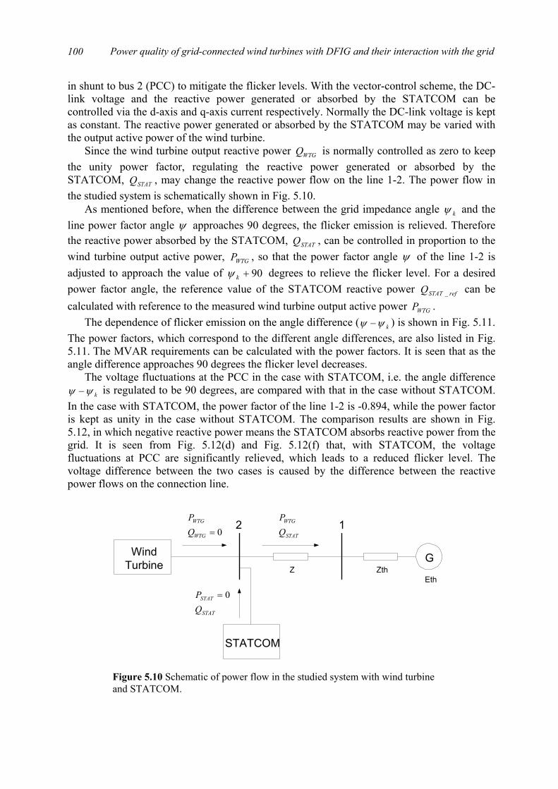
Power quality of grid-connected wind turbines with DFIG and their interaction with the grid
100
in shunt to bus 2 (PCC) to mitigate the flicker levels. With the vector-control scheme, the DC-link voltage and the reactive power generated or absorbed by the STATCOM can be controlled via the d-axis and q-axis current respectively. Normally the DC-link voltage is kept as constant. The reactive power generated or absorbed by the STATCOM may be varied with the output active power of the wind turbine.
Since the wind turbine output reactive power WTGQ is normally controlled as zero to keep the unity power factor, regulating the reactive power generated or absorbed by the STATCOM, STATQ , may change the reactive power flow on the line 1-2. The power flow in the studied system is schematically shown in Fig. 5.10.
As mentioned before, when the difference between the grid impedance angle kψ and the line power factor angle ψ approaches 90 degrees, the flicker emission is relieved. Therefore the reactive power absorbed by the STATCOM, STATQ , can be controlled in proportion to the wind turbine output active power, WTGP , so that the power factor angle ψ of the line 1-2 is adjusted to approach the value of 90+kψ degrees to relieve the flicker level. For a desired power factor angle, the reference value of the STATCOM reactive power refSTATQ _ can be calculated with reference to the measured wind turbine output active power WTGP .
The dependence of flicker emission on the angle difference ( kψψ − ) is shown in Fig. 5.11. The power factors, which correspond to the different angle differences, are also listed in Fig. 5.11. The MVAR requirements can be calculated with the power factors. It is seen that as the angle difference approaches 90 degrees the flicker level decreases.
The voltage fluctuations at the PCC in the case with STATCOM, i.e. the angle difference kψψ − is regulated to be 90 degrees, are compared with that in the case without STATCOM.
In the case with STATCOM, the power factor of the line 1-2 is -0.894, while the power factor is kept as unity in the case without STATCOM. The comparison results are shown in Fig. 5.12, in which negative reactive power means the STATCOM absorbs reactive power from the grid. It is seen from Fig. 5.12(d) and Fig. 5.12(f) that, with STATCOM, the voltage fluctuations at PCC are significantly relieved, which leads to a reduced flicker level. The voltage difference between the two cases is caused by the difference between the reactive power flows on the connection line.
GZ Zth
Eth
2 1
WindTurbine
STATCOM
STAT
STAT
QP 0=
0=WTG
WTG
QP
STAT
WTG
QP
Figure 5.10 Schematic of power flow in the studied system with wind turbine and STATCOM.
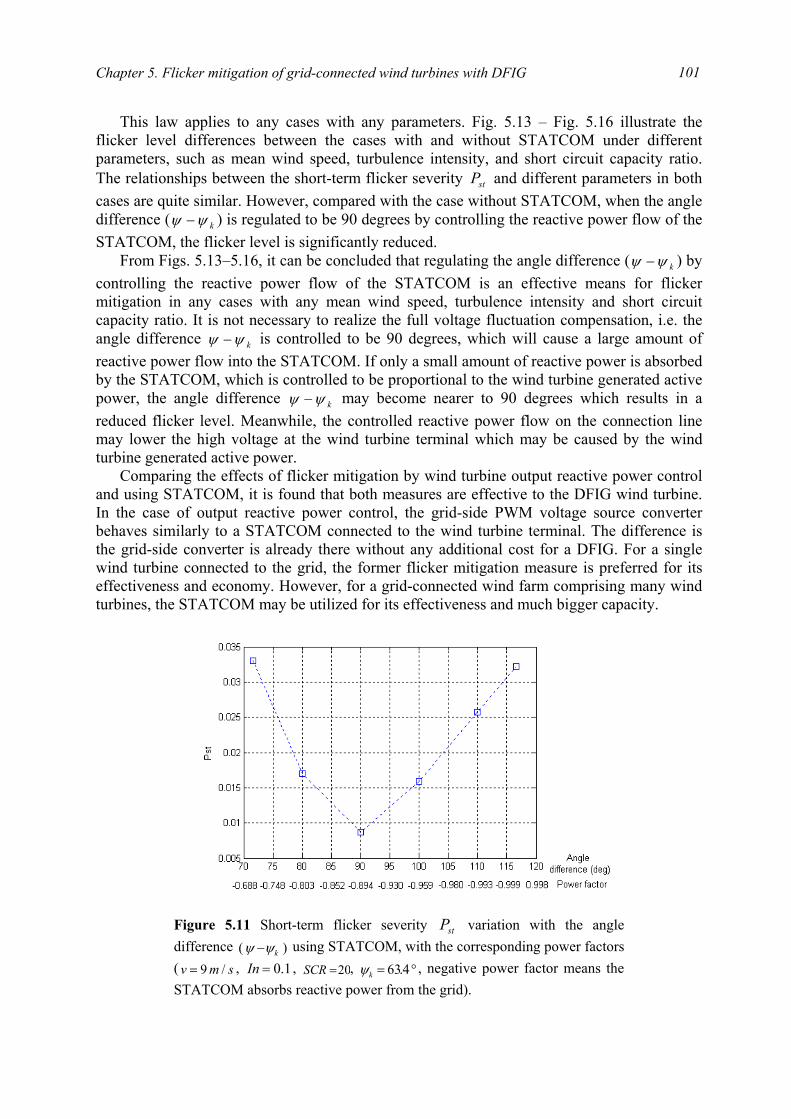
Chapter 5. Flicker mitigation of grid-connected wind turbines with DFIG
101
This law applies to any cases with any parameters. Fig. 5.13 – Fig. 5.16 illustrate the flicker level differences between the cases with and without STATCOM under different parameters, such as mean wind speed, turbulence intensity, and short circuit capacity ratio. The relationships between the short-term flicker severity stP and different parameters in both cases are quite similar. However, compared with the case without STATCOM, when the angle difference ( kψψ − ) is regulated to be 90 degrees by controlling the reactive power flow of the STATCOM, the flicker level is significantly reduced.
From Figs. 5.13–5.16, it can be concluded that regulating the angle difference ( kψψ − ) by controlling the reactive power flow of the STATCOM is an effective means for flicker mitigation in any cases with any mean wind speed, turbulence intensity and short circuit capacity ratio. It is not necessary to realize the full voltage fluctuation compensation, i.e. the angle difference kψψ − is controlled to be 90 degrees, which will cause a large amount of reactive power flow into the STATCOM. If only a small amount of reactive power is absorbed by the STATCOM, which is controlled to be proportional to the wind turbine generated active power, the angle difference kψψ − may become nearer to 90 degrees which results in a reduced flicker level. Meanwhile, the controlled reactive power flow on the connection line may lower the high voltage at the wind turbine terminal which may be caused by the wind turbine generated active power.
Comparing the effects of flicker mitigation by wind turbine output reactive power control and using STATCOM, it is found that both measures are effective to the DFIG wind turbine. In the case of output reactive power control, the grid-side PWM voltage source converter behaves similarly to a STATCOM connected to the wind turbine terminal. The difference is the grid-side converter is already there without any additional cost for a DFIG. For a single wind turbine connected to the grid, the former flicker mitigation measure is preferred for its effectiveness and economy. However, for a grid-connected wind farm comprising many wind turbines, the STATCOM may be utilized for its effectiveness and much bigger capacity.
Figure 5.11 Short-term flicker severity stP variation with the angle difference )( kψψ − using STATCOM, with the corresponding power factors( smv /9= , 1.0=In , 20=SCR , °= 4.63kψ , negative power factor means the STATCOM absorbs reactive power from the grid).
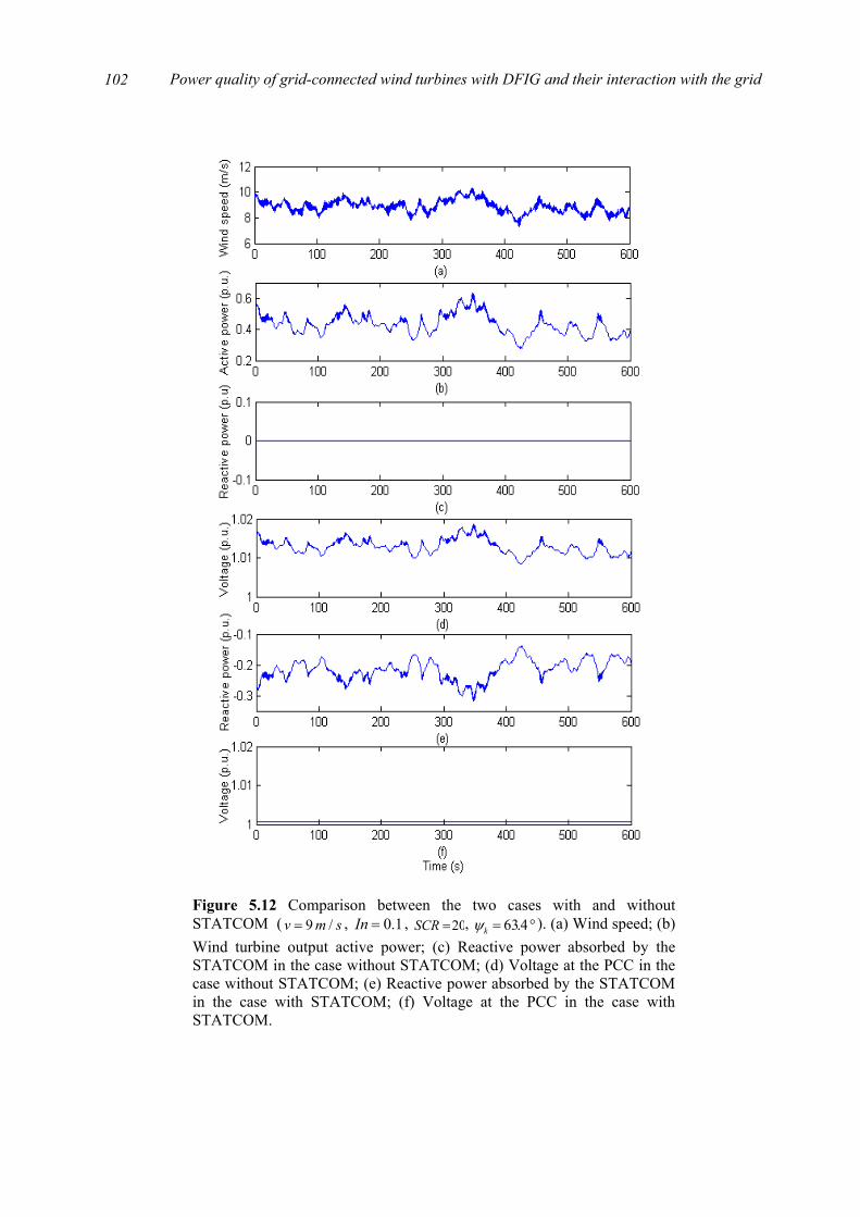
Power quality of grid-connected wind turbines with DFIG and their interaction with the grid
102
Figure 5.12 Comparison between the two cases with and withoutSTATCOM ( smv /9= , 1.0=In , 20=SCR , °= 4.63kψ ). (a) Wind speed; (b)Wind turbine output active power; (c) Reactive power absorbed by theSTATCOM in the case without STATCOM; (d) Voltage at the PCC in thecase without STATCOM; (e) Reactive power absorbed by the STATCOMin the case with STATCOM; (f) Voltage at the PCC in the case withSTATCOM.
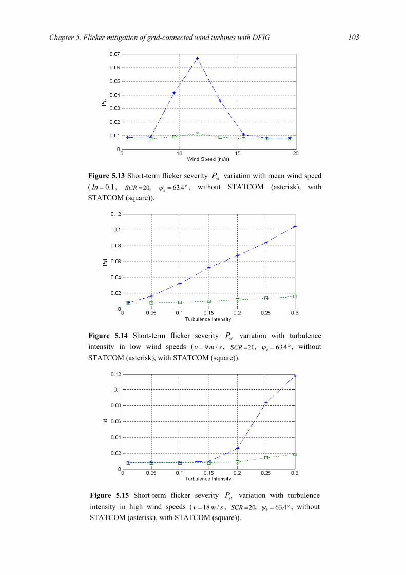
Chapter 5. Flicker mitigation of grid-connected wind turbines with DFIG
103
Figure 5.13 Short-term flicker severity stP variation with mean wind speed( 1.0=In , 20=SCR , °= 4.63kψ , without STATCOM (asterisk), withSTATCOM (square)).
Figure 5.15 Short-term flicker severity stP variation with turbulenceintensity in high wind speeds ( smv /18= , 20=SCR , °= 4.63kψ , withoutSTATCOM (asterisk), with STATCOM (square)).
Figure 5.14 Short-term flicker severity stP variation with turbulence intensity in low wind speeds ( smv /9= , 20=SCR , °= 4.63kψ , without STATCOM (asterisk), with STATCOM (square)).

Power quality of grid-connected wind turbines with DFIG and their interaction with the grid
104
5.4 Summary
This chapter proposes two measures to mitigate the flicker levels produced by grid-
connected wind turbines with DFIG during continuous operation. These two measures are based on the idea of reactive power compensation, respectively by controlling the wind turbine output reactive power and using STATCOM.
The principle of flicker mitigation by reactive power compensation is described first. When the reactive power flow on the connection line is regulated to vary with the active power flow so that the power factor angle ψ may approach the value of 90+kψ , the flicker levels are reduced. In this situation, the voltage fluctuation caused by the active power flow is compensated by that caused by the reactive power flow.
Based on the principle, flicker mitigation is realized by controlling the wind turbine output reactive power and using STATCOM during the continuous operation of grid-connected wind turbines with DFIG. Simulation results demonstrate that these two measures are effective for flicker mitigation regardless of mean wind speed, turbulence intensity and short circuit capacity ratio.
Bibliography
[1] H. Fujita, S. Tominaga, H. Akagi, “Analysis and design of an advanced static VAr compensator using quad-series voltage-source inverters,” Proc. of 1995 Thirtieth IAS Annual Meeting, vol. 3, pp. 2565 – 2572, Oct. 1995.
[2] S. Tominaga, H. Fujita, H. Akagi, “Application of zero-voltage-switching to a DC voltage-controlled static VAr compensator using quad-series voltage-source inverters,”
Figure 5.16 Short-term flicker severity stP variation with short circuit capacity ratio ( smv /9= , 1.0=In , °= 4.63kψ , without STATCOM (asterisk), with STATCOM (square)).
Chapter 5. Flicker mitigation of grid-connected wind turbines with DFIG
105
Proc. of 1996 IEEE 27th Power Electronics Specialists Conference, vol. 1, pp. 482 – 488, June 1996.
[3] H. Fujita, S. Tominaga, H. Akagi, “Analysis and design of a DC voltage-controlled static VAr compensator using quad-series voltage-source inverters,” IEEE Trans. on Industry Applications, vol. 32, no. 4, pp. 970 – 978, July-Aug. 1996.
[4] H. Fujita, S. Tominaga, H. Akagi, “A practical approach to switching-loss reduction in a large-capacity static VAr compensator based on voltage-source inverters,” IEEE Trans. on Industry Applications, vol. 36, no. 5, pp. 1396 – 1404, Sept.-Oct. 2000.
[5] N. G. Hingorani, L. Gyugyi, Understanding FACTS: Concepts and technology of flexible AC transmission systems, IEEE press, New York, 2000.
[6] Z. Zhang, N. R. Fahmi, W. T. Norris, “Flicker analysis and methods for electric arc furnace flicker (EAF) mitigation (a survey),” Proc. of 2001 IEEE Porto Power Tech Conference, vol. 1, pp. 6/1-6/6, Sep. 2001.
[7] T. Larsson, C. Poumarède, “STATCOM, an efficient means for flicker mitigation,” Proc. of the IEEE Power Engineering Society 1999 Winter Meeting, pp. 1208-1213, Jan./Feb. 1999.
[8] J. E. Hill, “A practical example of the use of distribution static compensator (D-STATCOM) to reduce voltage fluctuation,” Proc. of the IEE Colloquium on Power Electronics for Renewable Energy, pp. 7/1-7/5, Jun. 1997.
[9] P. Giroux, G. Sybille, H. Le-Huy, “Modeling and simulation of a distribution STATCOM using simulink’s power system blockset,” Proc. of the 27th Annual Conference of the IEEE Industrial Electronics Society, vol. 2, pp. 990-994, Nov./ Dec., 2001.

Power quality of grid-connected wind turbines with DFIG and their interaction with the grid
106

Part IV
Voltage recovery of grid-connected wind turbines
at an external short-circuit fault

109
Chapter 6
Voltage recovery of grid-connected wind turbines with dynamic slip control
The continuous increase of wind power penetration level brings a result that wind power generation gradually becomes an important component of power generation in the grid, which makes the study on the interaction between the wind turbines and the grid necessary and imperative, especially in some critical situations.
The system operators, who are responsible for maintaining power system stability and reliable power supply, have formulated specifications regarding grid integration of wind power generation. According to the specification in Denmark [1], at a short-circuit fault in the external grid, the voltages at the wind turbine terminals should be re-established after the fault clearance without any power loss caused by disconnection of wind turbines. The similar requirements can be found in the specifications in Germany, the Netherlands, England and Wales [2]. The reason is, when the wind power penetration level is high, a number of thermal power plants in the power system are closed so that the available power reserves is reduced, then the protective disconnection of a large amount of wind power will be an unacceptable consequence that may threaten the power system stability.
To investigate the voltage recovery issue of grid-connected wind turbines with DFIG after the clearance of an external short-circuit fault is a basic motivation for this research work. The analysis is started with the voltage recovery issue of grid-connected wind turbines with dynamic slip control, which are simple, cost-effective, partially variable speed wind turbines, for gaining a good understanding of the transient responses of induction generators in an external short-circuit situation.
Regarding fixed speed wind turbines with conventional induction generators, the voltage recovery after the clearance of an external system fault may be assisted with dynamic reactive compensation, adjustment of relay settings of wind turbines, and control ability of wind turbines [3-5]. Adjusting the protective relay settings may be necessary for the wind turbines to stay grid-connected for a longer time during the fault situations, which makes it possible to re-establish the voltage with other means. The requirement of adjusting the protection relay settings has been reflected in the specifications for grid integration of wind power generation [2]. In this investigation, the overcurrent and undervoltage relay settings are chosen as shown in Table 6.1 [3].
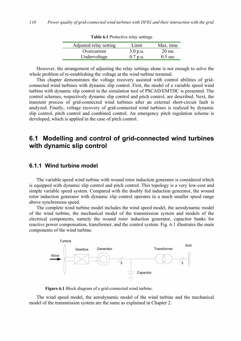
Power quality of grid-connected wind turbines with DFIG and their interaction with the grid
110
Table 6.1 Protective relay settings
Adjusted relay setting Limit Max. time Overcurrent 3.0 p.u. 20 ms
Undervoltage 0.7 p.u. 0.5 sec However, the arrangement of adjusting the relay settings alone is not enough to solve the
whole problem of re-establishing the voltage at the wind turbine terminal. This chapter demonstrates the voltage recovery assisted with control abilities of grid-
connected wind turbines with dynamic slip control. First, the model of a variable speed wind turbine with dynamic slip control in the simulation tool of PSCAD/EMTDC is presented. The control schemes, respectively dynamic slip control and pitch control, are described. Next, the transient process of grid-connected wind turbines after an external short-circuit fault is analyzed. Finally, voltage recovery of grid-connected wind turbines is realized by dynamic slip control, pitch control and combined control. An emergency pitch regulation scheme is developed, which is applied in the case of pitch control.
6.1 Modelling and control of grid-connected wind turbines with dynamic slip control
6.1.1 Wind turbine model The variable speed wind turbine with wound rotor induction generator is considered which
is equipped with dynamic slip control and pitch control. This topology is a very low-cost and simple variable speed system. Compared with the doubly fed induction generator, the wound rotor induction generator with dynamic slip control operates in a much smaller speed range above synchronous speed.
The complete wind turbine model includes the wind speed model, the aerodynamic model of the wind turbine, the mechanical model of the transmission system and models of the electrical components, namely the wound rotor induction generator, capacitor banks for reactive power compensation, transformer, and the control system. Fig. 6.1 illustrates the main components of the wind turbine.
The wind speed model, the aerodynamic model of the wind turbine and the mechanical
model of the transmission system are the same as explained in Chapter 2.
Wind
Gearbox Generator Transformer
Turbine
Capacitor
Grid
3 3
Figure 6.1 Block diagram of a grid-connected wind turbine.

Chapter 6. Voltage recovery of grid-connected wind turbines with dynamic slip control
111
The simulation software PSCAD/EMTDC provides dedicated models for the electrical components of the wind turbine, namely induction generator, capacitor bank for reactive power compensation and transformer, etc. The generator in this study is a wound rotor induction machine. Besides the electromagnetic description, the generator model in PSCAD/EMTDC also contains the mechanical inertia of the generator rotor.
Wound rotor induction generators usually permit intervention via the slip rings. Wind turbines are subject to random periodic output fluctuations due to wind speed fluctuations, tower-shadowing effects, natural resonance of components, etc. Regulating the slip value can significantly relieve the drive train stress and reduce output power fluctuations. In this wound rotor induction generator model, an external resistor is connected to the rotor through power electronic devices and may be adjusted to change the generator slip.
6.1.2 Control schemes
The wind turbine may be controlled through two ways: dynamic slip control and pitch
control. It is possible for the wind turbine to adjust the electromagnetic torque and the aerodynamic torque by dynamic slip control and pitch control.
Dynamic slip control The induction generator electromagnetic torque – slip curves are shown in Fig. 6.2 [6],
where rr is the rotor resistance, 1s is a high slip value which will be explained later. It is seen from Fig. 6.2 that the rotor circuit resistance has a significant influence on the
electromagnetic torque – slip curves. As the rotor circuit resistance increases, the electromagnetic torque – slip curve moves towards the left, while the maximum value of the electromagnetic torque is kept constant. Therefore, when the load torque is constant, it is possible to regulating the generator slip by changing the rotor circuit resistance.
For a continuous adjustment of slip, a rapid change of rotor circuit average resistance between short-circuited rotor winding and full resistance of an external resistor in the rotor circuit can be implemented by a switching device as shown in Fig. 6.3 to produce output-smoothed or efficient operating areas [7]. Thus, in the partial-load area, low slip values can be set and altered slightly to achieve a high level of efficiency.
Slip
rr
Torque
1s
Figure 6.2 Diagrammatic sketch of induction generator electromagnetictorque – slip curves for different rotor resistances.
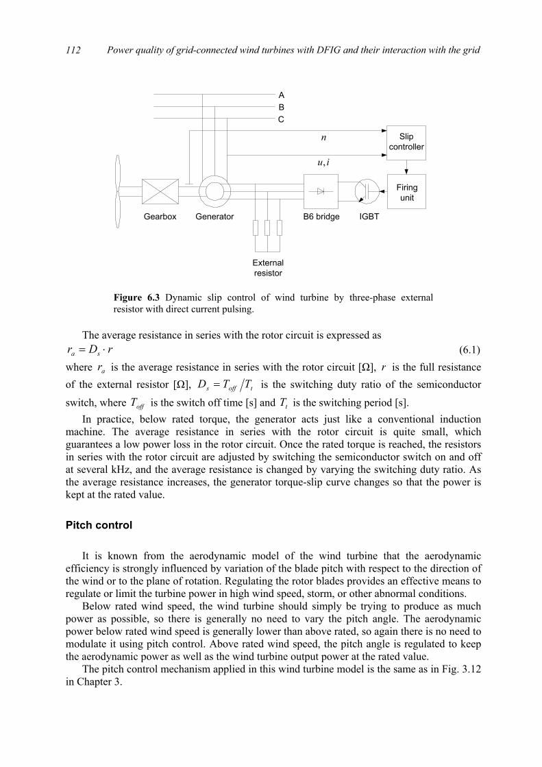
Power quality of grid-connected wind turbines with DFIG and their interaction with the grid
112
The average resistance in series with the rotor circuit is expressed as
rDr sa ⋅= (6.1) where ar is the average resistance in series with the rotor circuit [Ω], r is the full resistance of the external resistor [Ω], toffs TTD = is the switching duty ratio of the semiconductor
switch, where offT is the switch off time [s] and tT is the switching period [s]. In practice, below rated torque, the generator acts just like a conventional induction
machine. The average resistance in series with the rotor circuit is quite small, which guarantees a low power loss in the rotor circuit. Once the rated torque is reached, the resistors in series with the rotor circuit are adjusted by switching the semiconductor switch on and off at several kHz, and the average resistance is changed by varying the switching duty ratio. As the average resistance increases, the generator torque-slip curve changes so that the power is kept at the rated value.
Pitch control It is known from the aerodynamic model of the wind turbine that the aerodynamic
efficiency is strongly influenced by variation of the blade pitch with respect to the direction of the wind or to the plane of rotation. Regulating the rotor blades provides an effective means to regulate or limit the turbine power in high wind speed, storm, or other abnormal conditions.
Below rated wind speed, the wind turbine should simply be trying to produce as much power as possible, so there is generally no need to vary the pitch angle. The aerodynamic power below rated wind speed is generally lower than above rated, so again there is no need to modulate it using pitch control. Above rated wind speed, the pitch angle is regulated to keep the aerodynamic power as well as the wind turbine output power at the rated value.
The pitch control mechanism applied in this wind turbine model is the same as in Fig. 3.12 in Chapter 3.
Gearbox Generator
Firingunit
Externalresistor
B6 bridge IGBT
A
CB
Slipcontroller
n
iu,
Figure 6.3 Dynamic slip control of wind turbine by three-phase externalresistor with direct current pulsing.
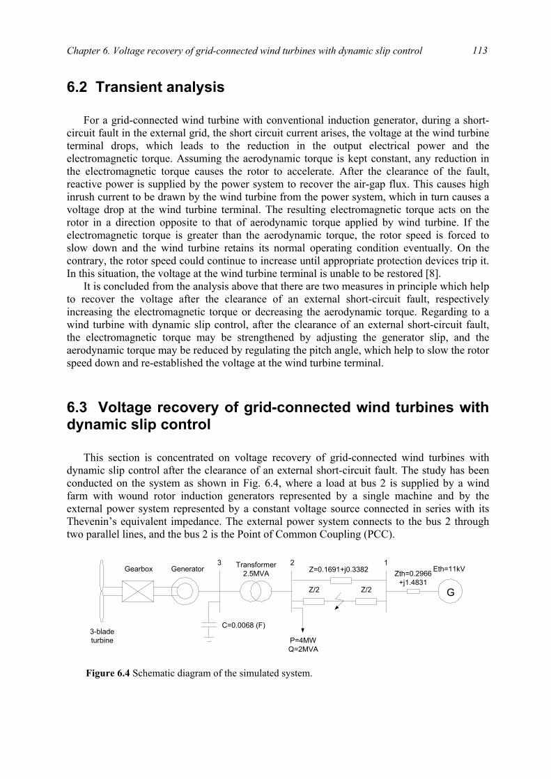
Chapter 6. Voltage recovery of grid-connected wind turbines with dynamic slip control
113
6.2 Transient analysis
For a grid-connected wind turbine with conventional induction generator, during a short-
circuit fault in the external grid, the short circuit current arises, the voltage at the wind turbine terminal drops, which leads to the reduction in the output electrical power and the electromagnetic torque. Assuming the aerodynamic torque is kept constant, any reduction in the electromagnetic torque causes the rotor to accelerate. After the clearance of the fault, reactive power is supplied by the power system to recover the air-gap flux. This causes high inrush current to be drawn by the wind turbine from the power system, which in turn causes a voltage drop at the wind turbine terminal. The resulting electromagnetic torque acts on the rotor in a direction opposite to that of aerodynamic torque applied by wind turbine. If the electromagnetic torque is greater than the aerodynamic torque, the rotor speed is forced to slow down and the wind turbine retains its normal operating condition eventually. On the contrary, the rotor speed could continue to increase until appropriate protection devices trip it. In this situation, the voltage at the wind turbine terminal is unable to be restored [8].
It is concluded from the analysis above that there are two measures in principle which help to recover the voltage after the clearance of an external short-circuit fault, respectively increasing the electromagnetic torque or decreasing the aerodynamic torque. Regarding to a wind turbine with dynamic slip control, after the clearance of an external short-circuit fault, the electromagnetic torque may be strengthened by adjusting the generator slip, and the aerodynamic torque may be reduced by regulating the pitch angle, which help to slow the rotor speed down and re-established the voltage at the wind turbine terminal.
6.3 Voltage recovery of grid-connected wind turbines with dynamic slip control
This section is concentrated on voltage recovery of grid-connected wind turbines with
dynamic slip control after the clearance of an external short-circuit fault. The study has been conducted on the system as shown in Fig. 6.4, where a load at bus 2 is supplied by a wind farm with wound rotor induction generators represented by a single machine and by the external power system represented by a constant voltage source connected in series with its Thevenin’s equivalent impedance. The external power system connects to the bus 2 through two parallel lines, and the bus 2 is the Point of Common Coupling (PCC).
Gearbox Generator
G
3-bladeturbine
C=0.0068 (F)
Transformer2.5MVA Zth=0.2966
+j1.4831
Eth=11kV
P=4MWQ=2MVA
3 2 1Z=0.1691+j0.3382
Z/2 Z/2
Figure 6.4 Schematic diagram of the simulated system.
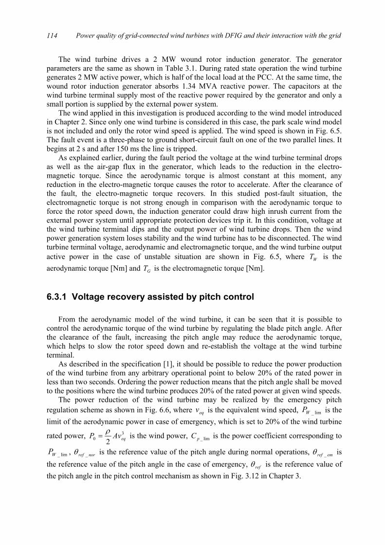
Power quality of grid-connected wind turbines with DFIG and their interaction with the grid
114
The wind turbine drives a 2 MW wound rotor induction generator. The generator parameters are the same as shown in Table 3.1. During rated state operation the wind turbine generates 2 MW active power, which is half of the local load at the PCC. At the same time, the wound rotor induction generator absorbs 1.34 MVA reactive power. The capacitors at the wind turbine terminal supply most of the reactive power required by the generator and only a small portion is supplied by the external power system.
The wind applied in this investigation is produced according to the wind model introduced in Chapter 2. Since only one wind turbine is considered in this case, the park scale wind model is not included and only the rotor wind speed is applied. The wind speed is shown in Fig. 6.5. The fault event is a three-phase to ground short-circuit fault on one of the two parallel lines. It begins at 2 s and after 150 ms the line is tripped.
As explained earlier, during the fault period the voltage at the wind turbine terminal drops as well as the air-gap flux in the generator, which leads to the reduction in the electro-magnetic torque. Since the aerodynamic torque is almost constant at this moment, any reduction in the electro-magnetic torque causes the rotor to accelerate. After the clearance of the fault, the electro-magnetic torque recovers. In this studied post-fault situation, the electromagnetic torque is not strong enough in comparison with the aerodynamic torque to force the rotor speed down, the induction generator could draw high inrush current from the external power system until appropriate protection devices trip it. In this condition, voltage at the wind turbine terminal dips and the output power of wind turbine drops. Then the wind power generation system loses stability and the wind turbine has to be disconnected. The wind turbine terminal voltage, aerodynamic and electromagnetic torque, and the wind turbine output active power in the case of unstable situation are shown in Fig. 6.5, where WT is the aerodynamic torque [Nm] and GT is the electromagnetic torque [Nm].
6.3.1 Voltage recovery assisted by pitch control From the aerodynamic model of the wind turbine, it can be seen that it is possible to
control the aerodynamic torque of the wind turbine by regulating the blade pitch angle. After the clearance of the fault, increasing the pitch angle may reduce the aerodynamic torque, which helps to slow the rotor speed down and re-establish the voltage at the wind turbine terminal.
As described in the specification [1], it should be possible to reduce the power production of the wind turbine from any arbitrary operational point to below 20% of the rated power in less than two seconds. Ordering the power reduction means that the pitch angle shall be moved to the positions where the wind turbine produces 20% of the rated power at given wind speeds.
The power reduction of the wind turbine may be realized by the emergency pitch regulation scheme as shown in Fig. 6.6, where eqv is the equivalent wind speed, lim_WP is the limit of the aerodynamic power in case of emergency, which is set to 20% of the wind turbine
rated power, 30 2 eqAvP ρ
= is the wind power, lim_pC is the power coefficient corresponding to
lim_WP , norref _θ is the reference value of the pitch angle during normal operations, emref _θ is the reference value of the pitch angle in the case of emergency, refθ is the reference value of the pitch angle in the pitch control mechanism as shown in Fig. 3.12 in Chapter 3.
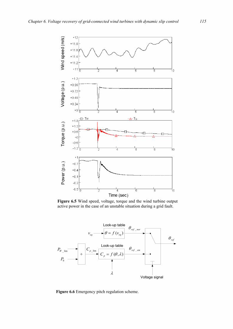
Chapter 6. Voltage recovery of grid-connected wind turbines with dynamic slip control
115
Figure 6.5 Wind speed, voltage, torque and the wind turbine outputactive power in the case of an unstable situation during a grid fault.
eqv
Look-up table
)( eqvf=θ
lim_WP
0P÷
Look-up table
),( λθfC p =
λ
lim_pC
norref _θ
emref _θ
Voltage signal
refθ
Figure 6.6 Emergency pitch regulation scheme.
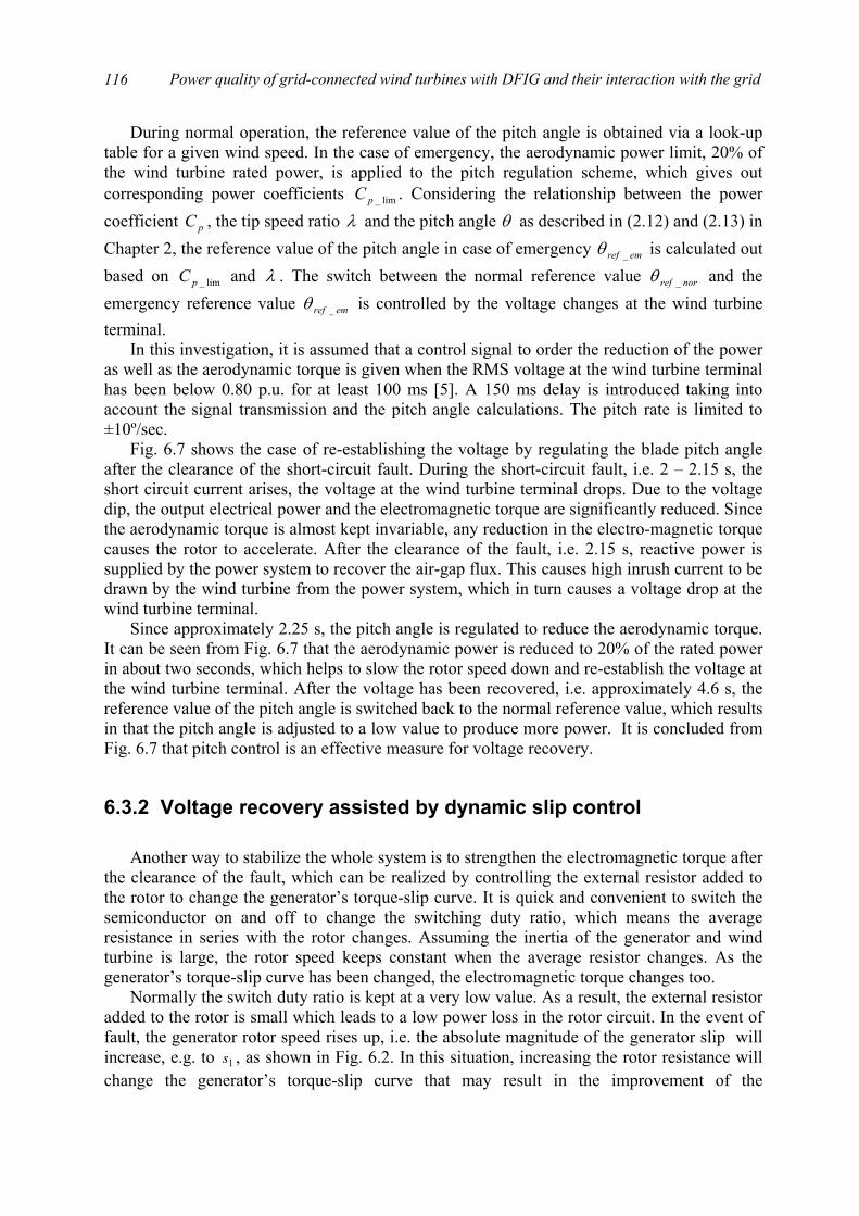
Power quality of grid-connected wind turbines with DFIG and their interaction with the grid
116
During normal operation, the reference value of the pitch angle is obtained via a look-up table for a given wind speed. In the case of emergency, the aerodynamic power limit, 20% of the wind turbine rated power, is applied to the pitch regulation scheme, which gives out corresponding power coefficients lim_pC . Considering the relationship between the power coefficient pC , the tip speed ratio λ and the pitch angle θ as described in (2.12) and (2.13) in Chapter 2, the reference value of the pitch angle in case of emergency emref _θ is calculated out based on lim_pC and λ . The switch between the normal reference value norref _θ and the emergency reference value emref _θ is controlled by the voltage changes at the wind turbine terminal.
In this investigation, it is assumed that a control signal to order the reduction of the power as well as the aerodynamic torque is given when the RMS voltage at the wind turbine terminal has been below 0.80 p.u. for at least 100 ms [5]. A 150 ms delay is introduced taking into account the signal transmission and the pitch angle calculations. The pitch rate is limited to ±10º/sec.
Fig. 6.7 shows the case of re-establishing the voltage by regulating the blade pitch angle after the clearance of the short-circuit fault. During the short-circuit fault, i.e. 2 – 2.15 s, the short circuit current arises, the voltage at the wind turbine terminal drops. Due to the voltage dip, the output electrical power and the electromagnetic torque are significantly reduced. Since the aerodynamic torque is almost kept invariable, any reduction in the electro-magnetic torque causes the rotor to accelerate. After the clearance of the fault, i.e. 2.15 s, reactive power is supplied by the power system to recover the air-gap flux. This causes high inrush current to be drawn by the wind turbine from the power system, which in turn causes a voltage drop at the wind turbine terminal.
Since approximately 2.25 s, the pitch angle is regulated to reduce the aerodynamic torque. It can be seen from Fig. 6.7 that the aerodynamic power is reduced to 20% of the rated power in about two seconds, which helps to slow the rotor speed down and re-establish the voltage at the wind turbine terminal. After the voltage has been recovered, i.e. approximately 4.6 s, the reference value of the pitch angle is switched back to the normal reference value, which results in that the pitch angle is adjusted to a low value to produce more power. It is concluded from Fig. 6.7 that pitch control is an effective measure for voltage recovery.
6.3.2 Voltage recovery assisted by dynamic slip control Another way to stabilize the whole system is to strengthen the electromagnetic torque after
the clearance of the fault, which can be realized by controlling the external resistor added to the rotor to change the generator’s torque-slip curve. It is quick and convenient to switch the semiconductor on and off to change the switching duty ratio, which means the average resistance in series with the rotor changes. Assuming the inertia of the generator and wind turbine is large, the rotor speed keeps constant when the average resistor changes. As the generator’s torque-slip curve has been changed, the electromagnetic torque changes too.
Normally the switch duty ratio is kept at a very low value. As a result, the external resistor added to the rotor is small which leads to a low power loss in the rotor circuit. In the event of fault, the generator rotor speed rises up, i.e. the absolute magnitude of the generator slip will increase, e.g. to 1s , as shown in Fig. 6.2. In this situation, increasing the rotor resistance will change the generator’s torque-slip curve that may result in the improvement of the
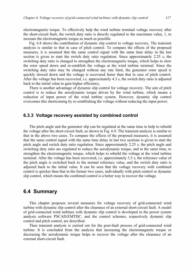
Chapter 6. Voltage recovery of grid-connected wind turbines with dynamic slip control
117
electromagnetic torque. To effectively help the wind turbine terminal voltage recovery after the short-circuit fault, the switch duty ratio is directly regulated to the maximum value, 1, to increase the electromagnetic torque as much as possible.
Fig. 6.8 shows the contribution of dynamic slip control to voltage recovery. The transient analysis is similar to that in case of pitch control. To compare the effects of the proposed measures, it is assumed that the same control signal with the same time delay in the last section is given to start the switch duty ratio regulation. Since approximately 2.25 s, the switching duty ratio is changed to strengthen the electromagnetic torque, which helps to slow the rotor speed down and re-establish the voltage at the wind turbine terminal. Since the switching duty ratio may be changed without any rate limit, the generator rotor speed is quickly slowed down and the voltage is recovered faster than that in case of pitch control. After the voltage has been recovered, i.e. approximately 4.3 s, the switch duty ratio is adjusted back to the initial value to gain higher efficiency.
There is another advantage of dynamic slip control for voltage recovery. The aim of pitch control is to reduce the aerodynamic torque driven by the wind turbine, which means a reduction of input power of the wind turbine system. However, dynamic slip control overcomes this shortcoming by re-establishing the voltage without reducing the input power.
6.3.3 Voltage recovery assisted by combined control The pitch angle and the generator slip can be regulated at the same time to help to rebuild
the voltage after the short-circuit fault, as shown in Fig. 6.9. The transient analysis is similar to that in the above two cases. To compare the effects of the proposed measures, it is assumed that the same control signal with the same time delay in last two sections is given to start the pitch angle and switch duty ratio regulation. Since approximately 2.25 s, the pitch angle and switching duty ratio are regulated to reduce the aerodynamic torque, and at the same time, to strengthen the electromagnetic torque, which helps to rebuild the voltage at the wind turbine terminal. After the voltage has been recovered, i.e. approximately 3.5 s, the reference value of the pitch angle is switched back to the normal reference value, and the switch duty ratio is adjusted back to the initial value. It can be seen that the voltage recovery with combined control is quicker than that in the former two cases, individually with pitch control or dynamic slip control, which means the combined control is a better way to recover the voltage.
6.4 Summary
This chapter proposes several measures for voltage recovery of grid-connected wind
turbine with dynamic slip control after the clearance of an external short-circuit fault. A model of grid-connected wind turbines with dynamic slip control is developed in the power system analysis software PSCAD/EMTDC, and the control schemes, respectively dynamic slip control and pitch control, are described.
Then transient analysis is carried out for the post-fault process of grid-connected wind turbine. It is concluded from the analysis that increasing the electromagnetic torque or decreasing the aerodynamic torque helps to recover the voltage after the clearance of an external short-circuit fault.
Power quality of grid-connected wind turbines with DFIG and their interaction with the grid
118
Figure 6.7 Wind speed, voltage, torque, generator rotor speed,current, active power and pitch angle in the case of pitch controlat voltage recovery.
Chapter 6. Voltage recovery of grid-connected wind turbines with dynamic slip control
119
Figure 6.8 Wind speed, voltage, torque, generator rotor speed,current, active power and switching duty ratio in the case ofdynamic slip control at voltage recovery.
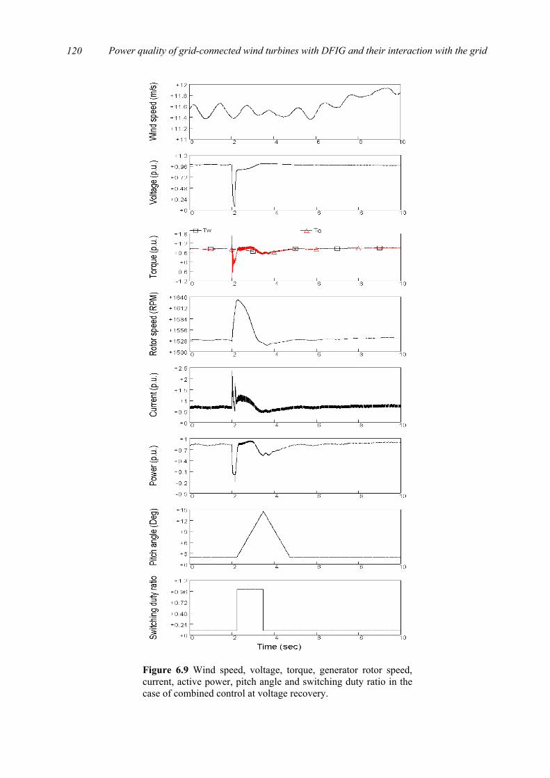
Power quality of grid-connected wind turbines with DFIG and their interaction with the grid
120
Figure 6.9 Wind speed, voltage, torque, generator rotor speed,current, active power, pitch angle and switching duty ratio in thecase of combined control at voltage recovery.
Chapter 6. Voltage recovery of grid-connected wind turbines with dynamic slip control
121
Regarding a wind turbine with dynamic slip control, after the clearance of an external short-circuit fault, the electromagnetic torque may be strengthened by adjusting the generator slip, and the aerodynamic torque may be reduced by regulating the pitch angle, which help to slow the rotor speed down and re-established the voltage at the wind turbine terminal. Simulation results demonstrate that pitch control, dynamic slip control and combined control are effective measures for voltage recovery of grid-connected wind turbines with dynamic slip control. An emergency pitch regulation scheme is developed and applied in the case of pitch control.
Bibliography
[1] ELTRA Transmission System Planning, Specifications for connecting wind farms to the transmission network, 2nd ed., ELT1999-411a, ELTRA Transmission System Planning, Apr. 2000.
[2] Generic Provisions Working Group. (2003, June). Background information to grid code consultation document D/03 [Online]. Available: http://www.nationalgrid.com/uk/indinfo/grid_code
[3] V. Akhmatov, Analysis of dynamic behaviour of electric power systems with large amount of wind power, Ph.D thesis, Electric Power Engineering, Technical University of Denmark, Apr. 2003.
[4] V. Akhmatov, H. Knudsen, A. H. Nielsen, J. K. Pedersen, N. K. Poulsen, “Modelling and transient stability of large wind farms,” Electrical Power and Energy Systems, vol. 25, no. 1, pp. 123-144, 2003.
[5] V. Akhmatov, H. Knudsen, A. H. Nielsen, N. K. Poulsen, J. K. Pedersen, “Short-term stability of large-scale wind farms,” Proc. of the European Wind Energy Conference, pp. 1182-1186, July 2001.
[6] F. H. Li, D. Q. Zhu, The electric machine, The Science Press, Beijing, third edition, 2002.
[7] S. Heier, Grid integration of wind energy conversion systems, John Wiley & Sons Ltd, Chichester, 1998.
[8] S. K. Salman, I. M. Rida, “Investigating the impact of embedded generation on relay settings of utilities’ electrical feeders,” IEEE Trans. on Power Delivery, vol. 16, no. 2, pp. 246-251, Apr. 2001.

Power quality of grid-connected wind turbines with DFIG and their interaction with the grid
122
123
Chapter 7
Voltage recovery of grid-connected wind turbines with DFIG
From the work carried out in Chapter 6, a good understanding is achieved with respect to the transient analysis of the post-fault process of grid-connected wind turbines. Several measures, such as increasing the electromagnetic torque or decreasing the aerodynamic torque after the fault clearance, are proved to be effective for voltage recovery of grid-connected wind turbines. Based on the acquired knowledge, the voltage recovery of grid-connected wind turbines with DFIG may be studied much easily.
Grid-connected wind turbines with DFIG, the most popular installed variable speed wind turbines worldwide, have shown better behaviours concerning system stability during short-circuit faults in the external grid in comparison with wind turbines with conventional induction generators [1, 2, 3]. One of the important reasons may be its control flexibility. Until now, there are few literatures related to voltage recovery of variable speed wind turbines with DFIG after the clearance of an external short-circuit fault.
This chapter studies the voltage recovery issue of grid-connected wind turbines with DFIG after the clearance of an external short-circuit fault, which starts from a description of the studied system and the protection scheme implemented in the DFIG. Then, the transient process of a grid-connected wind turbine with DFIG after an external short-circuit fault is analyzed. The performances of the wind turbine as well as the control schemes in the post-fault situation are described in detail. At last, in critical post-fault situations, a new control strategy is proposed to re-establish the wind turbine terminal voltage after the fault clearance, and then restore the normal operation of the wind turbine.
7.1 Studied system The studied system is illustrated in Fig. 7.1, which is much similar to the system in Fig.
6.4. The load at bus 2 is supplied by a wind farm with DFIG represented by a single machine and by the external power system represented by a constant voltage source connected in series with its Thevenin’s equivalent impedance. The external power system connects to bus 2 through two parallel lines, and bus 2 is the Point of Common Coupling (PCC).
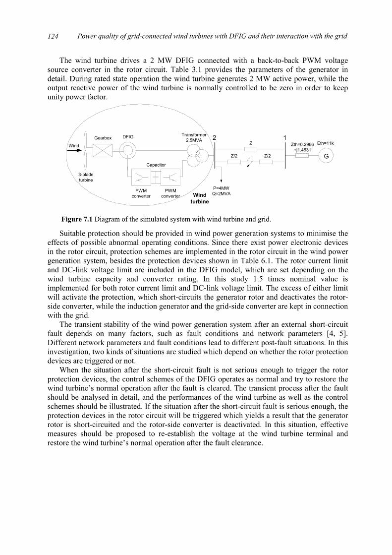
Power quality of grid-connected wind turbines with DFIG and their interaction with the grid
124
The wind turbine drives a 2 MW DFIG connected with a back-to-back PWM voltage source converter in the rotor circuit. Table 3.1 provides the parameters of the generator in detail. During rated state operation the wind turbine generates 2 MW active power, while the output reactive power of the wind turbine is normally controlled to be zero in order to keep unity power factor.
Suitable protection should be provided in wind power generation systems to minimise the
effects of possible abnormal operating conditions. Since there exist power electronic devices in the rotor circuit, protection schemes are implemented in the rotor circuit in the wind power generation system, besides the protection devices shown in Table 6.1. The rotor current limit and DC-link voltage limit are included in the DFIG model, which are set depending on the wind turbine capacity and converter rating. In this study 1.5 times nominal value is implemented for both rotor current limit and DC-link voltage limit. The excess of either limit will activate the protection, which short-circuits the generator rotor and deactivates the rotor-side converter, while the induction generator and the grid-side converter are kept in connection with the grid.
The transient stability of the wind power generation system after an external short-circuit fault depends on many factors, such as fault conditions and network parameters [4, 5]. Different network parameters and fault conditions lead to different post-fault situations. In this investigation, two kinds of situations are studied which depend on whether the rotor protection devices are triggered or not.
When the situation after the short-circuit fault is not serious enough to trigger the rotor protection devices, the control schemes of the DFIG operates as normal and try to restore the wind turbine’s normal operation after the fault is cleared. The transient process after the fault should be analysed in detail, and the performances of the wind turbine as well as the control schemes should be illustrated. If the situation after the short-circuit fault is serious enough, the protection devices in the rotor circuit will be triggered which yields a result that the generator rotor is short-circuited and the rotor-side converter is deactivated. In this situation, effective measures should be proposed to re-establish the voltage at the wind turbine terminal and restore the wind turbine’s normal operation after the fault clearance.
3-bladeturbine
GearboxTransformer
2.5MVA 2Wind
DFIG
Capacitor
PWMconverter
PWMconverter Wind
turbine
G
1Zth=0.2966
+j1.4831
P=4MWQ=2MVA
Z
Z/2 Z/2
Eth=11kV
Figure 7.1 Diagram of the simulated system with wind turbine and grid.

Chapter 7. Voltage recovery of grid-connected wind turbines with DFIG
125
7.2 Transient analysis of the post-fault process
This section analyses the post-fault process of the grid-connected wind turbine with DFIG
when the rotor protection devices are not triggered. In this study the wind turbine is connected to the external grid with two long-distance parallel lines, which corresponds to the impedance
3528.16764.0 jZ += . The wind speed applied here is produced according to the wind model introduced in Chapter 2. The fault event applied in this investigation is a single-phase to ground short-circuit fault at the mid-point of one of the two parallel lines. The fault begins at 2 s and after 150 ms the line is tripped. The simulation results for the transient process in the external short-circuit fault situation are shown in Fig. 7.2, where WT is the aerodynamic torque [Nm] and GT is the electromagnetic torque [Nm].
During the post-fault transient process, the DC-link voltage remains below 1.5 times nominal value, which will not trigger the protection devices in the rotor circuit. It is seen from the simulation results that the control schemes operate as normal and are capable of forcing the rotor speed down and re-establishing the voltage at the wind turbine terminal after the clearance of the short-circuit fault.
Immediately after the fault occurs, the stator voltage and flux drop, which results in the significant reduction in the electromagnetic torque and power. Since the aerodynamic torque is almost constant at this moment, any reduction in the electromagnetic torque causes the rotor to accelerate. After the fault is cleared at 2.15 s, as a result of control, the electromagnetic torque and power increase, which forces the generator rotor speed down. After a short time of oscillation, the voltage at the wind turbine terminal is rebuilt and the wind turbine retrieves its normal operation. During the transient process the control schemes try to control the wind turbine output reactive power as zero. It can also be noticed that the rotor-side active power increases when the DC-link voltage rises up during the fault.
The transient process is divided into two stages as follows, and in each stage the performances of the control schemes are analysed in detail. The corresponding simulation results are shown in Fig. 7.3 where the timing axis is zoomed.
7.2.1 During the fault It is learned from (3.13) in Chapter 3 that the DFIG stator-side active and reactive power
are (in generator mode)
)(2323
ss
sdr
s
mss
qrss
ms
Lwu
iLL
uQ
iuLL
P
−=
= (7.1)
Additionally, the electromagnetic torque is proportional to the q-axis rotor current (in generator mode) [6]:
qrs
s
s
mG i
wu
LL
pT23
= (7.2)
The control schemes of the DFIG have been illustrated in Fig. 3.4 and Fig. 3.6 in Chapter 3.

Power quality of grid-connected wind turbines with DFIG and their interaction with the grid
126
Immediately after the fault occurs at 2 s, the voltage at the wind turbine terminal drops. It is seen from (7.2) that the voltage dip will lead to a decrease of the electromagnetic torque, which is demonstrated in Fig. 7.3. Since the aerodynamic torque is almost kept constant at this moment, any reduction in the electromagnetic torque causes the generator rotor to increase.
It is known from (7.1) that, as the stator voltage dips, the stator-side active power sP decreases, which is identified in Fig. 7.3. The drop of sP causes the active power difference
srefs PPP −=∆ _ to increase. After the amplification by the PI-controller in Fig. 3.6, the active power difference increase results in the rise of the reference value of the q-axis rotor current
*qri , as shown in Fig.7.3.
Normally the stator-side reactive power sQ is controlled as zero, i.e. )(ss
sdr
s
m
Lwu
iLL
− in
(7.1) should be zero. When the short-circuit fault occurs, the stator voltage dips, which leads
to the increase of )(ss
sdr
s
m
Lwu
iLL
− from zero. Since the stator voltage su does not equal to zero,
the stator-side reactive power starts to rise from zero, which is identified in Fig. 7.3. Similarly, the rise of sQ makes the reactive power difference srefs QQQ −=∆ _ to decrease. After the amplification by the PI-controller in Fig. 3.6, the reactive power difference decrease results in the drop of the reference value of the d-axis rotor current *
dri , as illustrated in Fig.7.3. The variations of *
qri and *dri are reflected in the changes of the injected q- and d-axis rotor
voltage drqr uu , , which manage to control sP and sQ to approach their reference values, as demonstrated in Fig. 7.3.
As the fault occurs the DC-link voltage increases. However, the control scheme for the grid-side converter then tries to control the DC-link voltage back to its reference value as shown in Fig. 7.3.
7.2.2 After the clearance of the fault Once the short-circuit fault is cleared at 2.15 s, the voltage at the wind turbine terminal
starts to rise. It is known from (7.3) that the electromagnetic torque will increase with the voltage rise, which is evident in Fig. 7.3. As the aerodynamic torque is almost kept constant at this moment, the increasing electromagnetic torque forces the generator rotor speed down.
Similar to the analysis mentioned above, as a result of the voltage rise, the stator-side active power sP increases while the stator-side reactive power sQ decreases, which lead to
P∆ drop and Q∆ rise. After the amplification by the PI-controllers in Fig. 3.6, the power differences changes respectively result in *
qri decrease and *dri increase, as illustrated in
Fig.7.3. The variations of *qri and *
dri are reflected in the changes of the injected q- and d-axis
rotor voltage drqr uu , , which manage to control sP and sQ to approach their reference values. It is seen from Fig. 7.3 that the wind turbine restores its normal operation after a short-time oscillation.
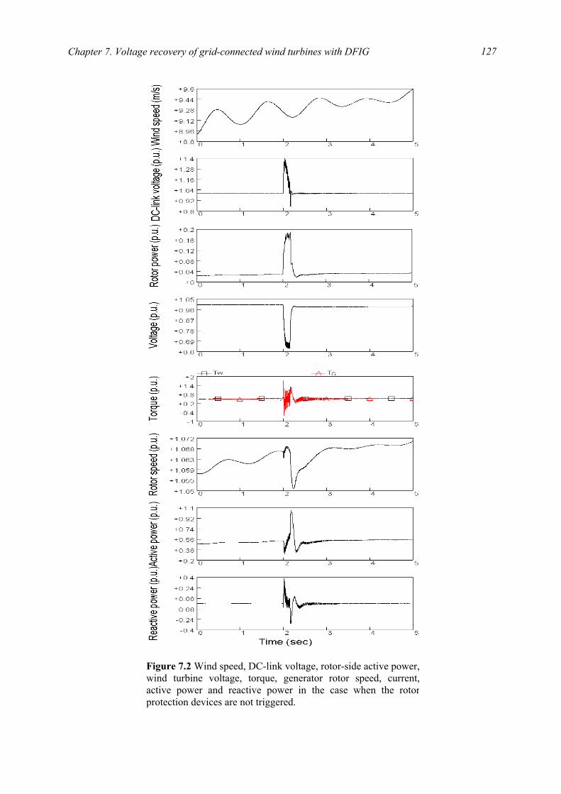
Chapter 7. Voltage recovery of grid-connected wind turbines with DFIG
127
Figure 7.2 Wind speed, DC-link voltage, rotor-side active power,wind turbine voltage, torque, generator rotor speed, current,active power and reactive power in the case when the rotorprotection devices are not triggered.
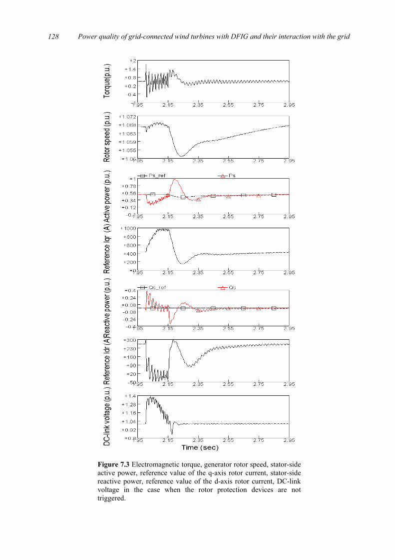
Power quality of grid-connected wind turbines with DFIG and their interaction with the grid
128
Figure 7.3 Electromagnetic torque, generator rotor speed, stator-sideactive power, reference value of the q-axis rotor current, stator-sidereactive power, reference value of the d-axis rotor current, DC-linkvoltage in the case when the rotor protection devices are nottriggered.
Chapter 7. Voltage recovery of grid-connected wind turbines with DFIG
129
7.3 Control strategy for voltage recovery
This section investigates the voltage recovery issue of grid-connected wind turbines with
DFIG when the rotor protection devices are triggered. In this study the wind turbine is connected to the external grid with two short-distance parallel lines, which corresponds to the impedance 3382.01691.0 jZ += . The wind speed applied here is produced according to the wind model introduced in Chapter 2. The fault event applied here is a three-phase to ground short-circuit fault at the mid-point of one of the two parallel lines. The fault begins at 2 s and after 150 ms the line is tripped.
A new control strategy is proposed to contribute to re-establish the voltage at the wind turbine terminal without any wind turbine disconnection after a short-circuit fault. This control strategy takes advantage of the benefits of pitch controlled variable speed wind turbine. To carry out the control strategy, the emergency pitch regulation scheme mentioned in Chapter 6 is applied.
After an occurrence of a short-circuit fault in the external networks, the following control steps are performed:
1. The excess of either the rotor current limit or the DC-link voltage limit will activate the protection to short-circuit the generator rotor and deactivate the rotor-side converter, while the induction generator and the grid-side converter are kept in connection with the grid.
2. Regulating the pitch angle reduces the aerodynamic power, which helps to force the generator rotor speed down and re-establish the voltage at the wind turbine terminal.
3. After the clearance of the short-circuit fault and the voltage recovery of the wind turbine, the rotor-side converter is put back into work and the DFIG restores it normal operation.
In Fig. 7.4 the simulation results for the control strategy implemented in the studied system are shown, where WT is the aerodynamic torque [Nm] and GT is the electromagnetic torque [Nm]. The post-fault transient process is divided into three stages as follows.
7.3.1 Protection device activation Immediately after the fault occurs, the short-circuit current increases and the stator voltage
and flux drop towards zero. The rotor current also increases which causes the rise of the rotor voltage and the DC-link voltage. Meanwhile, the drop of the stator voltage and flux results in a significant reduction in the electromagnetic torque and power. Assuming the aerodynamic torque is kept constant, any reduction in the electromagnetic torque causes the rotor to accelerate.
Once the DC-link voltage exceeds the limit for at least 40 ms, at approximately 2.05 s, the generator rotor is short-circuited and the rotor-side converter is deactivated while the grid-side converter is kept in connection with the grid, which is responsible for keeping the DC-link voltage constant and ensuring zero reactive power flow between the converter and the grid. From this moment on, the generator behaves as a conventional induction generator. It has been noticed that the DC-link voltage begins to decrease after the protection trip and retains its nominal value quickly.

Power quality of grid-connected wind turbines with DFIG and their interaction with the grid
130
Figure 7.4 Wind speed, voltage, stator current, DC-link voltage,torque, generator rotor speed, active power, reactive power and pitchangle in the case when the rotor protection devices are triggered.
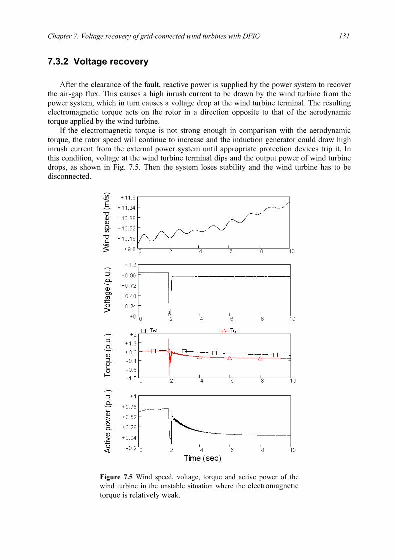
Chapter 7. Voltage recovery of grid-connected wind turbines with DFIG
131
7.3.2 Voltage recovery After the clearance of the fault, reactive power is supplied by the power system to recover
the air-gap flux. This causes a high inrush current to be drawn by the wind turbine from the power system, which in turn causes a voltage drop at the wind turbine terminal. The resulting electromagnetic torque acts on the rotor in a direction opposite to that of the aerodynamic torque applied by the wind turbine.
If the electromagnetic torque is not strong enough in comparison with the aerodynamic torque, the rotor speed will continue to increase and the induction generator could draw high inrush current from the external power system until appropriate protection devices trip it. In this condition, voltage at the wind turbine terminal dips and the output power of wind turbine drops, as shown in Fig. 7.5. Then the system loses stability and the wind turbine has to be disconnected.
Figure 7.5 Wind speed, voltage, torque and active power of thewind turbine in the unstable situation where the electromagnetic torque is relatively weak.
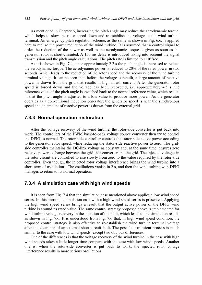
Power quality of grid-connected wind turbines with DFIG and their interaction with the grid
132
As mentioned in Chapter 6, increasing the pitch angle may reduce the aerodynamic torque, which helps to slow the rotor speed down and re-establish the voltage at the wind turbine terminal. An emergency pitch regulation scheme, as the same as shown in Fig. 6.6, is applied here to realize the power reduction of the wind turbine. It is assumed that a control signal to order the reduction of the power as well as the aerodynamic torque is given as soon as the generator rotor is short-circuited. A 150 ms delay is introduced taking into account the signal transmission and the pitch angle calculations. The pitch rate is limited to ±10°/sec.
As it is shown in Fig. 7.4, since approximately 2.2 s the pitch angle is increased to reduce the aerodynamic torque. The aerodynamic power is reduced to 20% of the rated power in two seconds, which leads to the reduction of the rotor speed and the recovery of the wind turbine terminal voltage. It can be seen that, before the voltage is rebuilt, a large amount of reactive power is drawn from the grid that results in high inrush current. After the generator rotor speed is forced down and the voltage has been recovered, i.e. approximately 4.5 s, the reference value of the pitch angle is switched back to the normal reference value, which results in that the pitch angle is adjusted to a low value to produce more power. As the generator operates as a conventional induction generator, the generator speed is near the synchronous speed and an amount of reactive power is drawn from the external grid.
7.3.3 Normal operation restoration After the voltage recovery of the wind turbine, the rotor-side converter is put back into
work. The controllers of the PWM back-to-back voltage source converter then try to control the DFIG as normal. The rotor-side controller controls the stator-side active power according to the generator rotor speed, while reducing the stator-side reactive power to zero. The grid-side controller maintains the DC-link voltage as constant and, at the same time, ensures zero reactive power exchange between the grid-side converter and the grid. The injected voltages in the rotor circuit are controlled to rise slowly from zero to the value required by the rotor-side controller. Even though, the injected rotor voltage interference brings the wind turbine into a short term of oscillations. The oscillations vanish in 2 s, and then the wind turbine with DFIG manages to retain to its normal operation.
7.3.4 A simulation case with high wind speeds It is seen from Fig. 7.4 that the simulation case mentioned above applies a low wind speed
series. In this section, a simulation case with a high wind speed series is presented. Applying the high wind speed series brings a result that the output active power of the DFIG wind turbine is around its rated value. The same control strategy proposed above is implemented for wind turbine voltage recovery in the situation of the fault, which leads to the simulation results as shown in Fig. 7.6. It is understood from Fig. 7.6 that, in high wind speed condition, the proposed control strategy is also effective to re-establish the wind turbine terminal voltage after the clearance of an external short-circuit fault. The post-fault transient process is much similar to the case with low wind speeds, except two obvious differences.
One of the differences is that the voltage recovery of the wind turbine in the case with high wind speeds takes a little longer time compare with the case with low wind speeds. Another one is, when the rotor-side converter is put back to work, the injected rotor voltage interference results in more serious oscillations.
Chapter 7. Voltage recovery of grid-connected wind turbines with DFIG
133
Figure 7.6 Wind speed, voltage, stator current, DC-link voltage,torque, generator rotor speed, active power, reactive power and pitchangle in the simulated case with a high wind speed series, where theproposed control strategy is implemented.
Power quality of grid-connected wind turbines with DFIG and their interaction with the grid
134
7.4 Summary
This chapter focuses on voltage recovery issue of grid-connected wind turbines with
DFIG. The transient process after the external short-circuit fault are classified as two kinds of cases, which depends on whether the rotor protection devices are triggered or not.
When the situation after the short-circuit fault is not serious enough to trigger the rotor protection devices, the control schemes of the DFIG operates as normal and are capable of forcing the rotor speed down and re-establishing the voltage at the wind turbine terminal after the clearance of the short-circuit fault, which are demonstrated by simulation results. The performances of the wind turbine as well as the control schemes are illustrated in detail.
If the situation after the short-circuit fault is serious enough, the protection devices in the rotor circuit will be triggered which yields a result that the generator rotor is short-circuited and the rotor-side converter is deactivated. In this situation, a control strategy is proposed to re-establish the voltage at the wind turbine terminal and restore the wind turbine’s normal operation after the fault clearance, which is verified by simulations results. The control strategy, which takes advantage of the benefits of the rotor circuit protection device and the pitch control scheme, are performed in three steps, respectively protection device activation, voltage recovery assisted by pitch control, and normal operation restoration of the wind turbine with DFIG.
Bibliography
[1] J. Usaola, P. Ledesma, “Dynamic incidence of wind turbines in networks with high wind penetration,” Proc. of 2001 IEEE Power Engineering Society Summer Meeting, vol. 2, pp. 755-760, July 2001.
[2] T. Gjengedal, “Integration of wind power and the impact on power system operation,” Proc. of 2003 Large Engineering Systems Conference on Power Engineering, pp. 76-83, May 2003.
[3] L. Holdsworth, X. G. Wu, J. B. Ekanayake, N. Jenkins, “Comparison of fixed speed and doubly-fed induction wind turbines during power system disturbances,” IEE Proc. Gener. Transm. Distrib., vol. 150, no. 3, pp. 343-352, May 2003.
[4] S. K. Salman, A. L. J. Teo, “Windmill modeling consideration and factors influencing the stability of a grid-connected wind power-based embedded generator,” IEEE Trans. on Power Systems, vol. 18, no. 2, pp. 793-802, May 2003.
[5] L. Holdsworth, N. Jenkins, G. Strbac, “Electrical stability of large, offshore wind farms,” Proc. of the Seventh International Conference on AC-DC Power Transmission, pp. 156-161, Nov. 2001.
[6] R. Pena, J. C. Clare, G. M. Asher, “Doubly fed induction generator using back-to-back PWM converters and its application to variable-speed wind-energy generation,” IEE Proc. Electr. Power Appl., vol. 143, no. 3, pp. 231-241, May 1996.

Chapter 7. Voltage recovery of grid-connected wind turbines with DFIG
135
[7] J. B. Ekanayake, L. Holdsworth, X. G. Wu, N. Jenkins, “Dynamic modeling of doubly fed induction generator wind turbines,” IEEE Trans. on Power Systems, vol. 18, no. 2, pp. 803-809, May 2003.

Power quality of grid-connected wind turbines with DFIG and their interaction with the grid
136

Part V
Conclusion

139
Chapter 8
Conclusion
This thesis has examined power quality issues of grid-connected wind turbines and the interaction between wind turbines and the grid that they are connected to. The specific goal of the research has been to investigate flicker emission and mitigation of grid-connected wind turbines with DFIG during continuous operation, and voltage recovery of such kind of grid-connected wind turbines after the clearance of a short circuit fault in the grid. This will benefit integrating more wind power generation into the existing grid in the near future.
8.1 Summary of the thesis As a basis of the research, a model of grid-connected wind turbines with DFIG was
developed in the dedicated power system analysis tool PSCAD/EMTDC, which simulates the dynamics of the system from the turbine rotor where the kinetic wind energy is converted to mechanical energy, to the grid connection point where the electric power is fed into the grid. The complete grid-connected wind turbine model includes the wind speed model, the aerodynamic model of the wind turbine, the mechanical model of the transmission system, models of the electrical components, namely the DFIG, PWM voltage source converters, transformer, capacitor, and the control system. The grid model and the electrical components of the wind turbine were built with standard electrical component models from PSCAD/EMTDC library. The wind model, the aerodynamic model, the mechanical model and the control system were built with custom components developed in PSCAD/EMTDC.
Two control schemes were implemented in the developed grid-connected wind turbine model: speed control and pitch control. The speed control scheme is composed by two vector-control schemes designed respectively for the rotor-side and grid-side PWM voltage source converter. The objective of the vector-control scheme for the grid-side PWM voltage source converter is to keep the DC-link voltage constant regardless of the magnitude and direction of the rotor power. It may also be responsible for controlling reactive power flow into the grid. The vector-control scheme for the rotor-side PWM voltage source converter ensures decoupling control of stator-side active and reactive power drawn from the grid. It provides the generator with wide speed-range operation, which enables the optimal speed tracking for maximum energy capture from the wind. Cascade control was used in the vector-control
Power quality of grid-connected wind turbines with DFIG and their interaction with the grid
140
schemes. Two design methods, pole-placement and internal model control, were applied for designing the PI-controllers in the vector-control schemes. The pitch control scheme was employed to regulate the aerodynamic power from the turbine.
The performances of the control schemes, respectively current control loops, power control loops, DC-link voltage control loop and pitch control loop, were illustrated, which meet the design requirements. The wind turbine is capable of providing satisfactory steady state and dynamic performances, which makes it possible that the wind turbine model can be applied to study the power quality issues of such kind of grid-connected wind turbines and their interaction with the grid.
To meet the purpose of the research project, two aims were formulated. The first aim of the research was
to study the flicker emission and mitigation of grid-connected wind turbines with DFIG during continuous operation. The flicker levels and the influence factors that affect the flicker levels must be studied, and, based on the research results, some effective measures to mitigate the flicker levels must be put forward.
The flicker emission produced by grid-connected wind turbines during continuous operation is mainly caused by fluctuations in the output power due to wind speed variations, the wind gradient and the tower shadow effect. Any fluctuations in the active or reactive power produced by grid-connected wind turbines result in voltage fluctuations and flicker at the coupling point of the wind turbines. To evaluate the flicker levels produced by grid-connected wind turbines with DFIG, a flickermeter model was developed according to the IEC standard IEC 61000-4-15, which simulates the response of the lamp-eye-brain chain and provides on-line statistical analysis of the flicker signal and the final results.
Based on the developed model of grid-connected wind turbines with DFIG and the flickermeter model, the flicker emission during continuous operation was studied. The influence factors, such as wind characteristics (mean speed, turbulence intensity) and grid conditions (short circuit capacity, grid impedance angle) have significant effects on the flicker emission of the variable speed wind turbine with DFIG. The effects of the influence factors are compared with previous research results related to the fixed speed wind turbine. In particular, the effects of mean wind speed, turbulence intensity and grid impedance angle are different from that in the case of the fixed speed wind turbine.
It is possible to regulate the reactive power flow on the connection line so that the voltage fluctuation caused by the active power flow can be compensated by that caused by the reactive power flow. Based on this principle, two effective measures were proposed to mitigate the flicker levels produced by grid-connected wind turbines with DFIG, respectively by wind turbine output reactive power control and using STATCOM.
The variable speed wind turbine with DFIG is capable of controlling the output active and reactive power independently. The wind turbine output reactive power was regulated to vary with the output active power by the grid-side PWM voltage source converter control, thus the wind turbine power factor angle was changed to relieve the flicker levels.
A STATCOM was connected in shunt to the Point of Common Coupling of the grid-connected wind turbine for flicker mitigation. The model and control scheme of the STATCOM were described in detail. The STATCOM is capable of changing the reactive power flow on the connection line so that the power factor angle is changed which results in reduced flicker levels.
The second aim of the research was
Chapter 8. Conclusion
141
to analyse the transient process of grid-connected wind turbines with DFIG at a short-circuit fault in the external grid, and in critical post-fault situations, to propose effective measures for voltage recovery of grid-connected wind turbines with DFIG after the fault clearance. To meet this aim, the analysis is started with voltage recovery of grid-connected wind
turbines with dynamic slip control, which are simple, cost-effective, partially variable speed wind turbines, for gaining a good understanding of transient responses of induction generators in an external short-circuit situation.
The model of a variable speed wind turbine with dynamic slip control in the simulation tool of PSCAD/EMTDC was presented, and the control schemes, respectively dynamic slip control and pitch control, were described. The transient process of grid-connected wind turbines after an external short-circuit fault was analyzed in detail. It was concluded from the analysis that increasing the electromagnetic torque or decreasing the aerodynamic torque helps to recover the voltage after the clearance of an external short-circuit fault. For the wind turbine with dynamic slip control, after the clearance of an external short-circuit fault, the electromagnetic torque was strengthened by adjusting the generator slip, and the aerodynamic torque was reduced by regulating the pitch angle, which helped to slow the rotor speed down and re-established the voltage at the wind turbine terminal. An emergency pitch regulation scheme is developed and applied in the case of pitch control.
Based on the acquired knowledge, the voltage recovery of grid-connected wind turbines with DFIG may be studied much easily. Two kinds of situations were studied which depend on whether the rotor protection devices in the DFIG were triggered or not.
When the situation after an external short-circuit fault was not serious enough to trigger the rotor protection devices, the control schemes of the DFIG operated as normal and were capable of forcing the rotor speed down and re-establishing the voltage at the wind turbine terminal after the clearance of the short-circuit fault. The performances of the wind turbine as well as the control schemes were illustrated in detail.
If the situation after an external short-circuit fault is serious enough, the protection devices in the rotor circuit will be triggered which yields a result that the generator rotor is short-circuited and the rotor-side converter is deactivated. In this situation, a control strategy was proposed to re-establish the voltage at the wind turbine terminal and restore the wind turbine’s normal operation after the fault clearance. The control strategy, which takes advantage of the benefits of the rotor circuit protection device and the pitch control scheme, were performed in three steps, respectively protection device activation, voltage recovery assisted by pitch control, and normal operation restoration of the wind turbine with DFIG.
8.2 Conclusions and new contributions
By the results presented in this thesis it is believed that all objectives of the research
project have been fulfilled. To meet the two aims stated in Chapter 1 many new research results have been achieved. This has led to the main conclusions and recommendations summarized below – along with the novel aspects of the research.
Power quality of grid-connected wind turbines with DFIG and their interaction with the grid
142
Wind turbine model
• A whole model of grid-connected wind turbines with DFIG in PSCAD/EMTDC has been developed, including the control system. Although the wind turbine model and the control system are developed based on the traditional theories, it is useful and has proved to be able to support the study of the power quality issues of such kind of grid-connected wind turbines and their interaction with the grid.
Flicker emission and mitigation
• The flicker emission of grid-connected wind turbines with DFIG during continuous operation has been investigated. The dependences of flicker emission on the mean wind speed, turbulence intensity, short circuit capacity ratio and grid impedance angle were illustrated in detail and compared with previous research results related to fixed speed wind turbines. This is believed new and will benefit understanding the nature of flicker emission of grid-connected wind turbines.
• Two measures have been proposed to mitigate the flicker levels produced by grid-connected wind turbines with DFIG, respectively by wind turbine output reactive power control and using STATCOM. These two measures are based on the idea of reactive power compensation. In this way, the voltage fluctuations caused by the active power flow can be compensated by that caused by the reactive power flow. The two measures are considered – and have been proved to be – very effective and novel means for flicker mitigation of grid-connected wind turbines with DFIG.
Voltage recovery
• For grid-connected wind turbines with dynamic slip control, it is concluded that, after the clearance of an external short-circuit fault, the electromagnetic torque may be strengthened by adjusting the generator slip, and the aerodynamic torque may be reduced by regulating the pitch angle, which effectively helps to slow the rotor speed down and re-establish the voltage at the wind turbine terminal. The measure of combined control is considered novel for voltage recovery of grid-connected wind turbines with dynamic slip control.
• With respect to grid-connected wind turbines with DFIG, when the situation after an external short-circuit fault was not serious enough to trigger the rotor protection devices, the control schemes of the DFIG operates as normal and are capable of forcing the rotor speed down and re-establishing the voltage at the wind turbine terminal after the clearance of the short-circuit fault. The transient responses of the wind turbine as well as the control schemes have been analysed in detail, which are of great significance.
• If the situation after an external short-circuit fault is serious enough, the protection devices in the rotor circuit will be triggered which yields a result that the generator rotor is short-circuited and the rotor-side converter is deactivated. In this situation, a control
Chapter 8. Conclusion
143
strategy was proposed to re-establish the voltage at the wind turbine terminal and restore the wind turbine’s normal operation after the fault clearance. The control strategy, which are performed in three steps, respectively protection device activation, voltage recovery assisted by pitch control, and normal operation restoration of the wind turbine with DFIG, has been proved to be effective and novel.
8.3 Future work
Although many works have been accomplished in this thesis, several future investigations
are interesting. Some subjects for future studies are listed in the following.
• Saturation effects should be included in the induction generator and the transformer models.
• A detailed PWM voltage source converter model with high-frequency switches should be implemented in the DFIG wind power generation system. It might provide more accurate transient responses for grid-connected wind turbines with DFIG. The overload of the power converter should also be considered.
• Complete Protection schemes should be developed for the DFIG, which includes under- and over- voltage, over-current, speed- and frequency- deviation protection, as well as the protection scheme for the power converter. The power converter blocking and the device applied to short-circuit the generator rotor, such as crowbar, should also be implemented.
• It is possible to realize the voltage recovery of grid-connected wind turbines by using STATCOM. The control strategies of reactive power compensation after an external short-circuit fault, as well as the cost-benefit analysis, should also be investigated and verified.
• The transient behaviours of the DFIG wind turbine under the disturbances of other grid failures should be studied.
• The performances of the DFIG wind turbine may be compared with that of the wind turbine with a multi-pole permanent magnet generator, which is connected to the grid through a full-scale power converter. The benefits and the disadvantages should be analysed.
• If possible, field tests should be carried out to verify the simulation results documented in this thesis. With the verification work, the proposed measures and control strategies could be improved.
• Flicker study and voltage recovery issue investigation should be carried out on a wind farm, which comprises many wind turbines. The interaction between the wind turbines in the wind farm should be included.

Power quality of grid-connected wind turbines with DFIG and their interaction with the grid
144

Part VI
Appendices

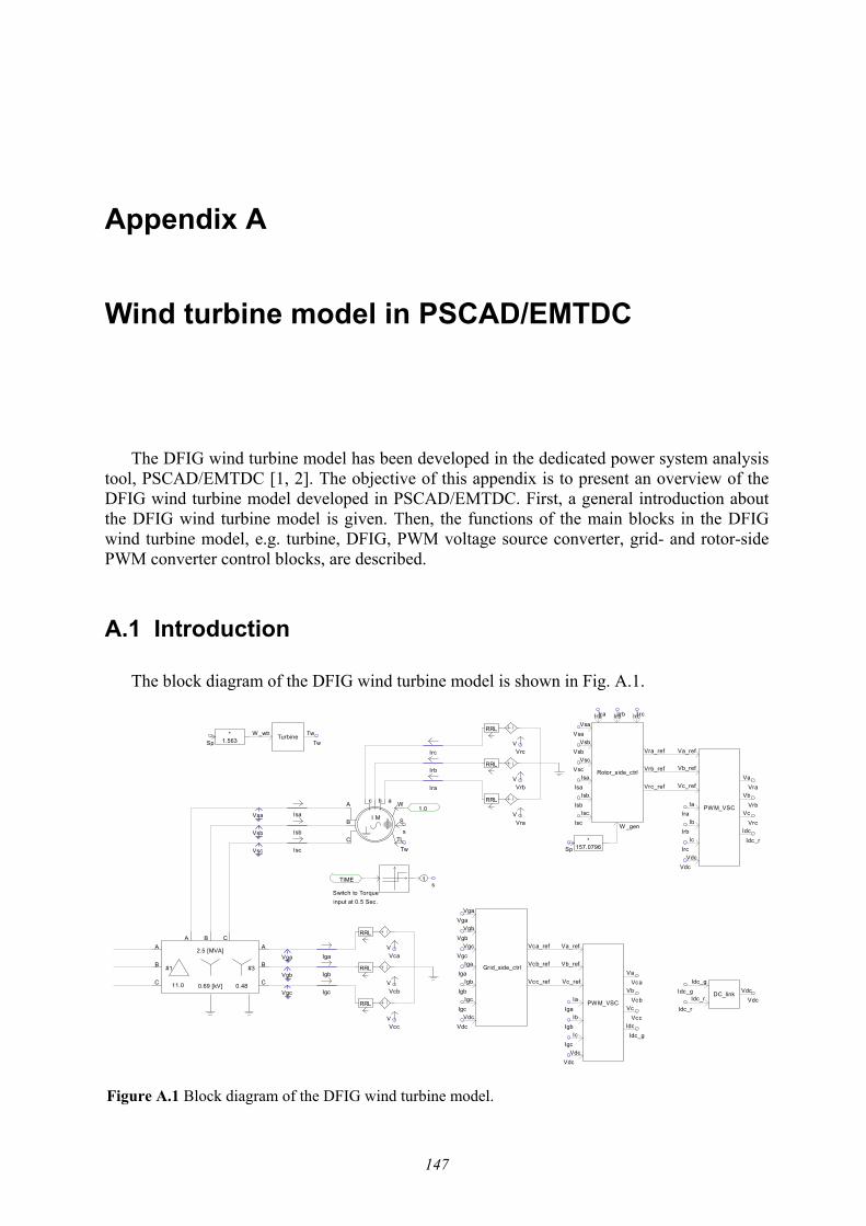
147
Appendix A
Wind turbine model in PSCAD/EMTDC
The DFIG wind turbine model has been developed in the dedicated power system analysis tool, PSCAD/EMTDC [1, 2]. The objective of this appendix is to present an overview of the DFIG wind turbine model developed in PSCAD/EMTDC. First, a general introduction about the DFIG wind turbine model is given. Then, the functions of the main blocks in the DFIG wind turbine model, e.g. turbine, DFIG, PWM voltage source converter, grid- and rotor-side PWM converter control blocks, are described.
A.1 Introduction
The block diagram of the DFIG wind turbine model is shown in Fig. A.1.
Vsb
Vsa
Vsc
RRL
V
S
TLC
A
BI M
b c W a
RRL
VVga
Vgb
Vgc
Iga
Igb
Igc
RRL
V
Isa
Isc
Isb
Ira
Irb
Irc
RRL
V
RRL
V
RRL
V
s
1
Switch to Torqueinput at 0.5 Sec.
sTIME
1.0
Sp*
1.563
Tw
TwTurbine TwW _wtr
Vga
Vgb
Vgc
Iga
Igb
IgcIb
Ic
Vdc
Va
VcIa
Vc_ref
Vb_ref
Va_ref
Vb
PWM_VSC
Idc
Iga
Igc
IgbVdc
Vca
Vcb
Vcc
Vca
Vcb
Vcc
Rotor_side_ctrl
Ira Irb Irc
Vsa
Vsb
Vsc
Isa
Isb
Isc
Vra_ref
Vrb_ref
Vrc_ref
W _gen
Ia
Ib
Ic
Vdc
Va
Vb
Idc
Va_ref
Vb_ref
Vc_ref
VcPWM_VSC
Vga
Vgb
Vgc
Iga
Igb
Igc
Vdc
Grid_side_ctrl
Vca_ref
Vcb_ref
Vcc_ref
Vsa
Vsb
Vsc
Isa
Isb
Isc
Ira Irb Irc
*157.0796Sp
Ira
Irb
Irc
Vra
Vrb
Vrc
Vra
Vrb
Vrc
Vdc
Idc_g
Idc_g
Idc_r
Idc_r
DC_link VdcIdc_g
Idc_r
Vdc
Vdc
A
B
C
A
B
C
A B C
2.5 [MVA]
11.0 0.69 [kV] 0.48
#1 #3
Figure A.1 Block diagram of the DFIG wind turbine model.
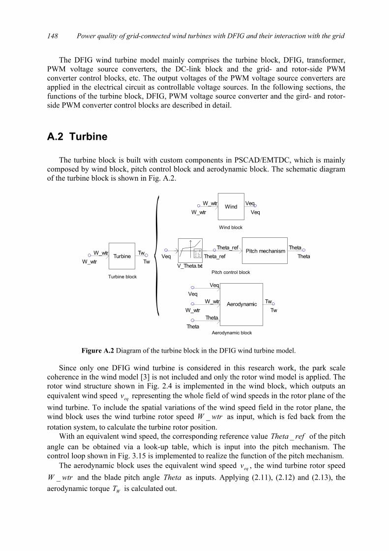
Power quality of grid-connected wind turbines with DFIG and their interaction with the grid
148
The DFIG wind turbine model mainly comprises the turbine block, DFIG, transformer, PWM voltage source converters, the DC-link block and the grid- and rotor-side PWM converter control blocks, etc. The output voltages of the PWM voltage source converters are applied in the electrical circuit as controllable voltage sources. In the following sections, the functions of the turbine block, DFIG, PWM voltage source converter and the gird- and rotor-side PWM converter control blocks are described in detail.
A.2 Turbine
The turbine block is built with custom components in PSCAD/EMTDC, which is mainly
composed by wind block, pitch control block and aerodynamic block. The schematic diagram of the turbine block is shown in Fig. A.2.
Since only one DFIG wind turbine is considered in this research work, the park scale
coherence in the wind model [3] is not included and only the rotor wind model is applied. The rotor wind structure shown in Fig. 2.4 is implemented in the wind block, which outputs an equivalent wind speed eqv representing the whole field of wind speeds in the rotor plane of the wind turbine. To include the spatial variations of the wind speed field in the rotor plane, the wind block uses the wind turbine rotor speed wtrW _ as input, which is fed back from the rotation system, to calculate the turbine rotor position.
With an equivalent wind speed, the corresponding reference value refTheta _ of the pitch angle can be obtained via a look-up table, which is input into the pitch mechanism. The control loop shown in Fig. 3.15 is implemented to realize the function of the pitch mechanism.
The aerodynamic block uses the equivalent wind speed eqv , the wind turbine rotor speed wtrW _ and the blade pitch angle Theta as inputs. Applying (2.11), (2.12) and (2.13), the
aerodynamic torque WT is calculated out.
W_wtr TwTwTurbineW_wtr
W_wtrVeqWindW_wtr
Veq
V_Theta.txt
Veq Theta_ref ThetaPitch mechanismTheta_ref Theta
W_wtr
Veq
Theta
Tw
Veq
AerodynamicW_wtr
Theta
Tw
Turbine block
Wind block
Pitch control block
Aerodynamic block
Figure A.2 Diagram of the turbine block in the DFIG wind turbine model.

Appendix A. Wind turbine model in PSCAD/EMTDC
149
A.3 DFIG
PSCAD/EMTDC software library provides a dedicated model of the wound rotor induction generator with rotor voltages interference, as shown in Fig. A.3. The wound rotor induction generator is modelled in the state variable form using generalized machine theory. The stator and the rotor windings are transformed to their two-phase equivalent using the dq0-transformation. The wound rotor induction generator model is built with detailed descriptions of the stator and rotor direct and quadrature axis currents (or flux linkages) and the rotor speed. Besides the electromagnetic description, the generator model in PSCAD/EMTDC also contains the mechanical inertia of the generator rotor.
The machine can either be operated in speed control mode or torque control mode. Normally, the machine is started in speed control mode with the input W and then switched over to torque control with the input TL after it reaches steady state. The input S is a control signal which switches to select speed control mode or torque control mode. The CBA ,, and
cba ,, are the electrical connection points for the stator and rotor phases.
A.4 PWM voltage source converter
To effectively improve the simulation speed, an average model without switches is applied to simulate the PWM voltage source converter in this research work [4]. The PWM converter block, built with custom component, is shown in Fig. A.4.
The inputs refcrefbrefa VVV ___ ,, are the reference values of the PWM converter output voltages, the outputs cba VVV ,, are the real values of the PWM converter output voltages, the inputs cba III ,, are the AC-side currents of the PWM converter, the input dcV and output dcI are the DC-side voltage and current of the PWM converter.
The average model assumes that the PWM voltage source converters will ideally reproduce the reference voltages from the control schemes, i.e. the outputs cba VVV ,, are the same as the inputs refcrefbrefa VVV ___ ,, . The output dcI can be calculated with (2.39).
The output voltages of the PWM voltage source converter, cba VVV ,, , are applied in the electrical circuit as controllable voltage sources. The output DC current is input into the DC-link block. Based on the DC currents from the rotor-side and grid-side converters and the value of the capacitor in the DC-link, the DC voltage can be calculated.
S
TLC
A
BI M
b c W a
Figure A.3 Diagram of the DFIG in the DFIG wind turbine model.
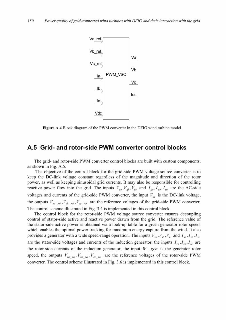
Power quality of grid-connected wind turbines with DFIG and their interaction with the grid
150
A.5 Grid- and rotor-side PWM converter control blocks
The grid- and rotor-side PWM converter control blocks are built with custom components,
as shown in Fig. A.5. The objective of the control block for the grid-side PWM voltage source converter is to
keep the DC-link voltage constant regardless of the magnitude and direction of the rotor power, as well as keeping sinusoidal grid currents. It may also be responsible for controlling reactive power flow into the grid. The inputs gcgbga VVV ,, and gcgbga III ,, are the AC-side voltages and currents of the grid-side PWM converter, the input dcV is the DC-link voltage, the outputs refccrefcbrefca VVV ___ ,, are the reference voltages of the grid-side PWM converter. The control scheme illustrated in Fig. 3.4 is implemented in this control block.
The control block for the rotor-side PWM voltage source converter ensures decoupling control of stator-side active and reactive power drawn from the grid. The reference value of the stator-side active power is obtained via a look-up table for a given generator rotor speed, which enables the optimal power tracking for maximum energy capture from the wind. It also provides a generator with a wide speed-range operation. The inputs scsbsa VVV ,, and scsbsa III ,, are the stator-side voltages and currents of the induction generator, the inputs rcrbra III ,, are the rotor-side currents of the induction generator, the input genW _ is the generator rotor speed, the outputs refrcrefrbrefra VVV ___ ,, are the reference voltages of the rotor-side PWM converter. The control scheme illustrated in Fig. 3.6 is implemented in this control block.
Ia
Ib
Ic
Va
Vc
Idc
VbPWM_VSC
Vc_ref
Vb_ref
Va_ref
Vdc
Figure A.4 Block diagram of the PWM converter in the DFIG wind turbine model.
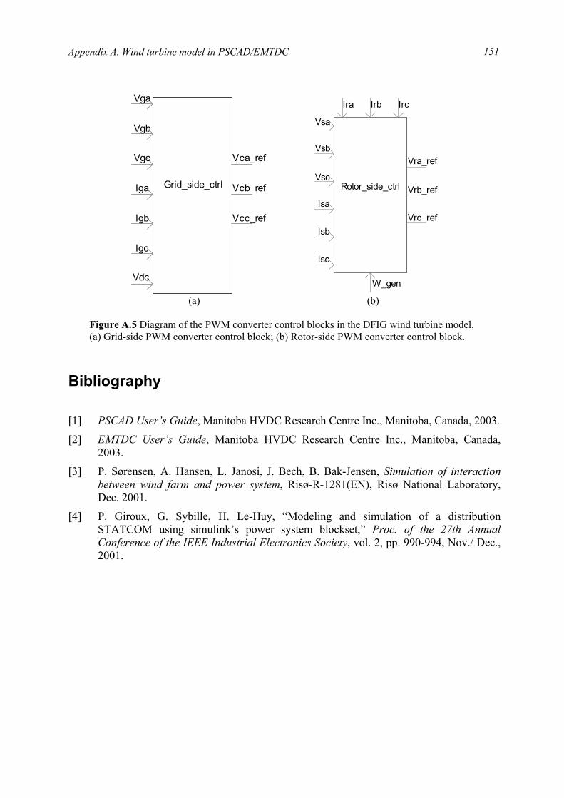
Appendix A. Wind turbine model in PSCAD/EMTDC
151
Bibliography
[1] PSCAD User’s Guide, Manitoba HVDC Research Centre Inc., Manitoba, Canada, 2003.
[2] EMTDC User’s Guide, Manitoba HVDC Research Centre Inc., Manitoba, Canada, 2003.
[3] P. Sørensen, A. Hansen, L. Janosi, J. Bech, B. Bak-Jensen, Simulation of interaction between wind farm and power system, Risø-R-1281(EN), Risø National Laboratory, Dec. 2001.
[4] P. Giroux, G. Sybille, H. Le-Huy, “Modeling and simulation of a distribution STATCOM using simulink’s power system blockset,” Proc. of the 27th Annual Conference of the IEEE Industrial Electronics Society, vol. 2, pp. 990-994, Nov./ Dec., 2001.
Vga
Vgb
Vgc
Iga
Igb
Igc
Vdc
Grid_side_ctrl Vcb_ref
Vca_ref
Vcc_ref
Ira Irb
Isb
Isc
Irc
W_gen
Vrc_ref
Vrb_ref
Vra_ref
Rotor_side_ctrl
Isa
Vsc
Vsb
Vsa
(a) (b) Figure A.5 Diagram of the PWM converter control blocks in the DFIG wind turbine model. (a) Grid-side PWM converter control block; (b) Rotor-side PWM converter control block.

Power quality of grid-connected wind turbines with DFIG and their interaction with the grid
152

153
Appendix B
System parameters
This appendix provides some parameters that are used in the simulation work, such as the impedance values in different grid conditions, and the protection settings of the wind turbine.
When the flicker emission and mitigation are studied in Chapter 4 and Chapter 5, the effects of the grid parameters (e.g. short circuit capacity and grid impedance angle) are included. Different grid conditions yield different impedance values, i.e. the values of Z and
thZ shown in Fig. 4.3. The impedance values in different grid conditions are listed in the following tables, where SCR is the short circuit capacity ratio, kψ is the grid impedance angle, which are shown in the captions of the figures in Chapter 4 and Chapter 5.
Table B.1 Impedance values with different SCR ( °= 50kψ )
SCR Z thZ 10 0.4861+j0.5793 3.8889+j4.6346 20 0.4861+j0.5793 1.9444+j2.3173 30 0.4861+j0.5793 1.2963+j1.5449 40 0.4861+j0.5793 0.9722+j1.1586 50 0.4861+j0.5793 0.7778+j0.9269 60 0.4861+j0.5793 0.6481+j0.7724 70 0.4861+j0.5793 0.5556+j0.6621 80 0.4861+j0.5793 0.4861+j0.5793 90 0.4861+j0.5793 0.4321+j0.5150 100 0.4861+j0.5793 0.3889+j0.4635
Table B.2 Impedance values with different SCR ( °= 4.63kψ )
SCR Z thZ 10 0.3382+j0.6764 2.7056+j5.4113 20 0.3382+j0.6764 1.3528+j2.7056 40 0.3382+j0.6764 0.6764+j1.3528 60 0.3382+j0.6764 0.4509+j0.9019 80 0.3382+j0.6764 0.3382+j0.6764 100 0.3382+j0.6764 0.2706+j0.5411

154 Power quality of grid-connected wind turbines with DFIG and their interaction with the grid
Table B.3 Impedance values with different kψ ( 20=SCR )
kψ (deg) Z thZ 0 0.7562+j0 3.0250+j0 10 0.7447+j0.1313 2.9790+j0.5253 20 0.7106+j0.2586 2.8426+j1.0346 30 0.6549+j0.3781 2.6197+j1.5125 40 0.5793+j0.4861 2.3173+j1.9444 50 0.4861+j0.5793 1.9444+j2.3173 60 0.3781+j0.6549 1.5125+j2.6197 70 0.2586+j0.7106 1.0346+j2.8426 80 0.1313+j0.7447 0.5253+j2.9790
82.5 0.0987+j0.7497 0.3948+j2.9991 85 0.0659+j0.7533 0.2636+j3.0135
87.5 0.0330+j0.7555 0.1319+j3.0221 90 0+j0.7562 0+j3.0250
Suitable protection should be provided in wind power generation systems to minimise the
effects of possible abnormal operating conditions. The protection relay settings of the DFIG wind turbines are given in Table B.4.
Table B.4 Protective relay settings
Protective relay settings Limit Max. time Overcurrent 3.0 p.u 20 ms
Undervoltage 0.7 p.u 0.5 sec Overcurrent (rotor circuit) 1.5 p.u 40 ms
Overvoltage (DC-link) 1.5 p.u 40 ms

155
Appendix C
Complete reference list
[1] European Wind Energy Association. (2003, March 3). Record growth for global wind power in 2002 [Online]. Available: http://www.ewea.org
[2] J. F. Manwell, J. G. McGowan, A. L. Rogers, Wind energy explained: theory, design and application, John Wiley & Sons Ltd, Chichester, 2002.
[3] T. Burton, D. Sharpe, N. Jenkins, E. Bossanyi, Wind energy handbook, John Wiley & Sons Ltd, Chichester, 2001.
[4] S. A. Papathanassiou, G. A. Vokas, M. P. Papadopoulos, “Use of power electronic converters in wind turbines and photovoltaic generators,” Proc. of the IEEE International Symposium on Industrial Electronics, vol. 1, pp. 254-259, July 1995.
[5] T. Ackermann, L. Söder, “An overview of wind energy-status 2002,” Renewable and Sustainable Energy Reviews, vol. 6, no. 1/2, pp. 67-127, 2002.
[6] L. H. Hansen, P. H. Madsen, F. Blaabjerg, H. C. Christensen, U. Lindhard, K. Eskildsen, “Generators and power electronics technology for wind turbines,” Proc. of the 27th Annual Conference of the IEEE on Industrial Electronics Society, vol. 3, pp. 2000-2005, Nov./Dec. 2001.
[7] L. Rossetto, P. Tenti, A. Zuccato, “Electromagnetic compatibility issues in industrial equipment,” IEEE Industry Application Magazine, vol. 5, Issue. 6, pp. 34-46, Nov./Dec. 1999.
[8] ELTRA Transmission System Planning, Specifications for connecting wind farms to the transmission network, 2nd ed., ELT1999-411a, ELTRA Transmission System Planning, Apr. 2000.
[9] Generic Provisions Working Group. (2003, June). Background information to grid code consultation document D/03 [Online]. Available: http://www.nationalgrid.com/uk/indinfo/grid_code
[10] T. Achermann, K. Garner, A. Gardiner, “Embedded wind generation in weak grids - economic optimization and power quality simulation,” Renewable Energy, vol. 18, no. 2, pp. 205-221, 1999.
Power quality of grid-connected wind turbines with DFIG and their interaction with the grid
156
[11] Åke Larsson, “Flicker emission of wind turbines during continuous operation,” IEEE Trans. on Energy Conversion, vol. 17, no. 1, pp. 114-118, Mar. 2002.
[12] G. Gerdes, F. Santjer, “Power quality of wind turbines and their interaction with the grid,” Proc. of Euro. Wind Energy Conf., pp. 1112-1115, Oct. 1994.
[13] D. A. Spera, Wind turbine technology: fundamental concepts of wind turbine engineering, ASME Press, New York, 1994.
[14] T. Thiringer, J. Dahlberg, “Periodic pulsations from a three-bladed wind turbine,” IEEE Trans. on Energy Conversion, vol. 16, no. 2, pp. 128-133, June 2001.
[15] T. Thiringer, “Power quality measurements performed on a low-voltage grid equipped with two wind turbines,” IEEE Trans. on Energy Conversion, vol. 11, no. 3, pp. 601-606, Sep. 1996.
[16] M. P. Papadopoulos, S. A. Papathanassiou, S. T. Tentzerakis, N. G. Boulaxis, “Investigation of the flicker emission by grid connected wind turbines,” Proc. of the 8th International Conference on Harmonics and Quality of Power, vol. 2, pp. 1152-1157, Oct. 1998.
[17] P. D. Ladakakos, M. G. Ioannides, M. I. Koulouvari, “Assessment of wind turbines impact on the power quality of autonomous weak grids,” Proc. of the 8th International Conference on Harmonics and Quality of Power, vol. 2, pp. 900-905, Oct. 1998.
[18] H. Amarís, C. Vilar, J. Usaola, J. L. Rodríguez, “Frequency domain analysis of flicker produced by wind energy conversions systems,” Proc. of the 8th International Conference on Harmonics and Quality of Power, vol. 2, pp. 1162-1167, Oct. 1998.
[19] H. Sharma, S. Islam, T. Pryor, C.V. Nayar, “Power quality issues in a wind turbine driven induction generator and diesel hybrid autonomous grid,” Journal of Electrical and Electronics Engineering, vol. 21, no. 1, pp. 19-25, 2001.
[20] Y. Kubota, T. Genji, K. Miyazato, N. Hayashi, H. Tokuda, Y. Fukuyama, “Verification of cooperative control method for voltage control equipment on distribution network simulator considering interconnection of wind power generators,” Proc. of Transmission and Distribution Conference and Exhibition 2002: Asia Pacific., vol. 2, pp. 1151-1156, Oct. 2002.
[21] Z. Zhang, N. R. Fahmi, W. T. Norris, “Flicker analysis and methods for electric arc furnace flicker (EAF) mitigation (a survey),” Proc. of 2001 IEEE Porto Power Tech Conference, vol. 1, pp. 6/1-6/6, Sep. 2001.
[22] T. Larsson, C. Poumarède, “STATCOM, an efficient means for flicker mitigation,” Proc. of the IEEE Power Engineering Society 1999 Winter Meeting, pp. 1208-1213, Jan./Feb. 1999.
[23] Z. Saad-Saoud, M. L. Lisboa, J. B. Ekanayake, N. Jenkins, G. Strbac, “Application of STATCOMs to wind farms,” IEE Proc. Gener. Transm. Distrib., vol. 145, no. 5, pp. 511-516, Sept. 1998.
[24] J. E. Hill, “A practical example of the use of distribution static compensator (D-STATCOM) to reduce voltage fluctuation,” Proc. of the IEE Colloquium on Power Electronics for Renewable Energy, pp. 7/1-7/5, Jun. 1997.
Appendix C. Complete reference list
157
[25] R. Grünbaum, “SVC Light: A powerful means for dynamic voltage and power quality control in industry and distribution,” Proc. of the Eighth International Conference on Power Electronics and Variable Speed Drives, pp. 404-409, Sept. 2000.
[26] A. Papantoniou, A. Coonick, “Simulation of FACTS for wind farm applications,” Proc. of the IEE Colloquium on Power Electronics for Renewable Energy, pp. 8/1-8/5, Jun. 1997.
[27] P. S. Dokopoulos, C. S. Dimoulias, I. M. Manousaridis, A. X. Patralexis, “Improvement of power quality in a grid with wind turbines using inductive storage,” Wind Engineering, vol. 23, no. 4, pp. 215-224, 1999.
[28] S. K. Salman, I. M. Rida, “Investigating the impact of embedded generation on relay settings of utilities’ electrical feeders,” IEEE Trans. on Power Delivery, vol. 16, no. 2, pp. 246-251, Apr. 2001.
[29] S. K. Salman, A. L. J. Teo, “Windmill modeling consideration and factors influencing the stability of a grid-connected wind power-based embedded generator,” IEEE Trans. on Power Systems, vol. 18, no. 2, pp. 793-802, May 2003.
[30] V. Akhmatov, H. Knudsen, “Modelling of windmill induction generators in dynamic simulation programs,” Proc. of International Conference on Electric Power Engineering, pp. 108, Aug./Sept. 1999.
[31] S. K. Salman, A. L. J. Teo, “Improvement of fault clearing time of wind farm using reactive power compensation,” Proc. of 2001 IEEE Porto Power Tech Conference, vol. 2, pp. 6/1-6/6, Sept. 2001.
[32] L. Holdsworth, N. Jenkins, G. Strbac, “Electrical stability of large, offshore wind farms,” Proc. of the Seventh International Conference on AC-DC Power Transmission, pp. 156-161, Nov. 2001.
[33] J. Usaola, P. Ledesma, “Dynamic incidence of wind turbines in networks with high wind penetration,” Proc. of 2001 IEEE Power Engineering Society Summer Meeting, vol. 2, pp. 755-760, July 2001.
[34] V. Akhmatov, H. Knudsen, A. H. Nielsen, N. K. Poulsen, J. K. Pedersen, “Short-term stability of large-scale wind farms,” Proc. of the European Wind Energy Conference, pp. 1182-1186, July 2001.
[35] T. Gjengedal, “Integration of wind power and the impact on power system operation,” Proc. of 2003 Large Engineering Systems Conference on Power Engineering, pp. 76-83, May 2003.
[36] L. Holdsworth, X. G. Wu, J. B. Ekanayake, N. Jenkins, “Comparison of fixed speed and doubly-fed induction wind turbines during power system disturbances,” IEE Proc. Gener. Transm. Distrib., vol. 150, no. 3, pp. 343-352, May 2003.
[37] P. Ledesma, J. Usaola, “Minimum voltage protections in variable speed wind farms,” Proc. of 2001 IEEE Porto Power Tech Conference, vol. 4, pp. 6/1-6/6, Sept. 2001.
[38] J. B. Ekanayake, L. Holdsworth, X. G. Wu, N. Jenkins, “Dynamic modeling of doubly fed induction generator wind turbines,” IEEE Trans. on Power Systems, vol. 18, no. 2, pp. 803-809, May 2003.
Power quality of grid-connected wind turbines with DFIG and their interaction with the grid
158
[39] International Electrotechnical Commission, Electromagnetic Compatibility (EMC) --- Part 4: Testing and measurement techniques --- Section 15: Flickermeter --- Functional and design specifications, IEC 61000-4-15, International Electrotechnical Commission, Geneva, Switzerland, Nov. 1997.
[40] P. Sørensen, A. Hansen, L. Janosi, J. Bech, B. Bak-Jensen, Simulation of interaction between wind farm and power system, Risø-R-1281(EN), Risø National Laboratory, Dec. 2001.
[41] P. Sørensen, A. D. Hansen, P. A. C. Rosas, “Wind models for simulation of power fluctuations from wind farms,” Journal of Wind Engineering and Industrial Aerodynamics, vol. 90, pp. 1381-1402, Dec. 2002.
[42] P. A. C. Rosas, P. Sørensen, H. Bindner, “Fast wind modeling for wind turbines,” Proc. of the Wind Power for the 21 Century: EUWER Special Topic Conference and Exhibition, pp. 184-187, Sept. 2000.
[43] S. Heier, Grid integration of wind energy conversion systems, John Wiley & Sons Ltd, Chichester, 1998.
[44] J. G. Slootweg, H. Polinder, W. L. Kling, “Dynamic modeling of a wind turbine with direct drive synchronous generator and back to back voltage source converter and its control,” Proc. of the European Wind Energy Conference, pp. 1014-1017, July 2001.
[45] Z. Chen, E. Spooner, “Grid power quality with variable speed wind turbines,” IEEE Trans. on Energy Conversion, vol. 16, no. 2, pp. 148-154, June 2001.
[46] I. Boldea, S.A. Nasar, The induction machine handbook, CRC Press, Boca Raton, 2002.
[47] F. H. Li, D. Q. Zhu, The electric machine, The Science Press, Beijing, third edition, 2002.
[48] J. D. Gao, X. H. Wang, F. H. Li, Analysis of alternative current electric machine system, The Qinghua Press, Beijing, 1993.
[49] Y. K. He, Computer simulation of alternative current electric machinery, The Science Press, Beijing, 1990.
[50] J. Chen, Mathematic model and speed-regulating system of alternative current electric machinery, The National Defense Industry Press, Beijing, 1989.
[51] M. Chomit, J. Bendl, L. Schreier, “Extended vector control of doubly fed machine under unbalanced power network conditions,” Proc. of the International Conference on Power Electronics, Machines and Drives, pp. 329-334, June 2002.
[52] N. Mohan, T. M. Undeland, W.P. Robbins, Power electronics – converters, applications, and design, John Wiley & Sons Inc, USA, third edition, 2003.
[53] A. M. Trzynadlowski, Introduction to modern power electronics, John Wiley & Sons Inc, New York, 1998.
[54] P. Giroux, G. Sybille, H. Le-Huy, “Modeling and simulation of a distribution STATCOM using simulink’s power system blockset,” Proc. of the 27th Annual Conference of the IEEE Industrial Electronics Society, vol. 2, pp. 990-994, Nov./ Dec., 2001.

Appendix C. Complete reference list
159
[55] P. Vas, Sensorless vector and direct torque control, Oxford University Press, New York, 1998.
[56] R. Pena, J. C. Clare, G. M. Asher, “Doubly fed induction generator using back-to-back PWM converters and its application to variable-speed wind-energy generation,” IEE Proc. Electr. Power Appl., vol. 143, no. 3, pp. 231-241, May 1996.
[57] B. Hopfensperger, D. J. Atkinson, R. A. Lakin, “Stator-flux-oriented control of a doubly-fed induction machine with and without position encoder,” IEE Proc. Electr. Power Appl., vol. 147, no. 4, pp. 241-250, July 2000.
[58] Y. Tang, L. Xu, “A flexible active and reactive power control strategy for a variable speed constant frequency generating system,” IEEE Trans. on Power Electronics, vol. 10, no. 4, pp. 472–478, July 1995.
[59] J. G. Ziegler, N. B. Nichols, “Optimum settings for automatic controllers,” Transactions of the ASME, vol. 64, pp. 759-768, 1942.
[60] S. E. Lyshevski, Control systems theory with engineering applications, Birkhäuser, Boston, 2001.
[61] R. S. Burns, Advanced control engineering, Butterworth-Heinemann, Oxford, 2001.
[62] R. N. Bateson, Introduction to control system technology, Prentice Hall, New Jersey, 1996.
[63] P. H. Lewis, C. Yang, Basic control system engineering, Prentice Hall, New Jersey, 1997.
[64] W. S. Levine, Control system fundamentals, CRC Press, Boca Raton, 2000.
[65] L. Harnefors, H. P. Nee, “Model-based current control of AC machines using the internal model control method,” IEEE Trans. on Industry Applications, vol. 34, no. 1, pp. 133-141, Jan./Feb. 1998.
[66] J. G. Zhang, Z. M. Chen, Z. C. Zhao, “A new antiwindup speed controller for induction motor drive system,” Proc. of the Fifth International Conference on Electrical Machines and Systems, vol. 2, pp. 1240-1243, Aug. 2001.
[67] L. Harnefors, H. P. Nee, “Robust current control of AC machines using the internal model control method,” Proc. of the 1995 IEEE Industry Applications conference, vol. 1, pp. 303-309, Oct. 1995.
[68] K. Hentabli, M. E. H. Benbouzid, D. Pinchon, “CGPC with internal model structure: Application to induction motor control,” Proc. of the 1997 IEEE International Conference on Control Applications, pp. 235-237, Oct. 1997.
[69] A. Petersson, Anylysis, modeling and control of doubly-fed induction generators for wind turbines, Ph.D thesis, Department of Electric Power Engineering, Chalmers University of Technology, 2003.
[70] J. H. S. Hansen, M. Lau, P. F. Sørensen, Sensorless control of a double fed induction generator, Institute of Energy Technology, Aalborg University, 1999.
[71] International Electrotechnical Commission, Wind turbine generator systems --- Part 21: measurement and assessment of power quality characteristics of grid connected wind
Power quality of grid-connected wind turbines with DFIG and their interaction with the grid
160
turbines, IEC 61400-21, International Electrotechnical Commission, Geneva, Switzerland, Dec. 2001.
[72] F. Blaabjerg, Z. Chen, “Power electronics as an enabling technology for renewable energy integration,” Journal of Power Electronics, vol. 3, no. 2, pp. 81-89, Apr. 2003.
[73] Research Institute for Danish Electric Utilities (DEFU), Connection of wind turbines to low and medium voltage networks, 2nd ed., DEFU KR-111, Research Institute for Danish Electric Utilities (DEFU), Oct. 1998.
[74] H. Fujita, S. Tominaga, H. Akagi, “Analysis and design of an advanced static VAr compensator using quad-series voltage-source inverters,” Proc. of 1995 Thirtieth IAS Annual Meeting, vol. 3, pp. 2565 – 2572, Oct. 1995.
[75] S. Tominaga, H. Fujita, H. Akagi, “Application of zero-voltage-switching to a DC voltage-controlled static VAr compensator using quad-series voltage-source inverters,” Proc. of 1996 IEEE 27th Power Electronics Specialists Conference, vol. 1, pp. 482 – 488, June 1996.
[76] H. Fujita, S. Tominaga, H. Akagi, “Analysis and design of a DC voltage-controlled static VAr compensator using quad-series voltage-source inverters,” IEEE Trans. on Industry Applications, vol. 32, no. 4, pp. 970 – 978, July-Aug. 1996.
[77] H. Fujita, S. Tominaga, H. Akagi, “A practical approach to switching-loss reduction in a large-capacity static VAr compensator based on voltage-source inverters,” IEEE Trans. on Industry Applications, vol. 36, no. 5, pp. 1396 – 1404, Sept.-Oct. 2000.
[78] N. G. Hingorani, L. Gyugyi, Understanding FACTS: Concepts and technology of flexible AC transmission systems, IEEE press, New York, 2000.
[79] V. Akhmatov, Analysis of dynamic behaviour of electric power systems with large amount of wind power, Ph.D thesis, Electric Power Engineering, Technical University of Denmark, Apr. 2003.
[80] V. Akhmatov, H. Knudsen, A. H. Nielsen, J. K. Pedersen, N. K. Poulsen, “Modelling and transient stability of large wind farms,” Electrical Power and Energy Systems, vol. 25, no. 1, pp. 123-144, 2003.
[81] PSCAD User’s Guide, Manitoba HVDC Research Centre Inc., Manitoba, Canada, 2003.
[82] EMTDC User’s Guide, Manitoba HVDC Research Centre Inc., Manitoba, Canada, 2003.
161
Appendix D
Published papers
In this appendix, a reprint of the scientific papers published on the work documented in this thesis is given. The six papers are:
[1] T. Sun, Z. Chen, F. Blaabjerg, “Voltage recovery of grid-connected wind turbines after a short-circuit fault,” Proc. of the 29th Annual Conference of the IEEE Industrial Electronics Society (IECON 2003), pp. 2723-2728, Nov. 2003.
[2] T. Sun, Z. Chen, F. Blaabjerg, “Transient analysis of grid-connected wind turbines with DFIG after an external short-circuit fault,” Proc. of the 2004 Nordic Wind Power Conference (NWPC 2004), pp. 5/1-5/5, Mar. 2004.
[3] T. Sun, Z. Chen, F. Blaabjerg, “Flicker mitigation of grid connected wind turbines using STATCOM,” Proc. of the Second International Conference on Power Electronics, Machines and Drives (PEMD 2004), Mar./Apr. 2004.
[4] T. Sun, Z. Chen, F. Blaabjerg, “Comparative study of voltage recovery behaviour of grid-connected wind turbines,” Proc. of the PCIM Europe 2004 (Power Electronics/Intelligent Motion/Power Quality), May 2004 (in press).
[5] T. Sun, Z. Chen, F. Blaabjerg, “Voltage recovery of grid-connected wind turbines with DFIG after a short-circuit fault,” Proc. of the 35th IEEE Power Electronics Specialists Conference (PESC 2004), Jun. 2004 (in press).
[6] T. Sun, Z. Chen, F. Blaabjerg, “Flicker study on variable speed wind turbines with doubly fed induction generators,” IEEE Trans. on Energy Conversion (in press).
Further, a complete list of the scientific papers published by the author is found on the next page.
Power quality of grid-connected wind turbines with DFIG and their interaction with the grid
162
The scientific papers published by the author
[1] T. Sun, H. X. Zhao, H. Shen, W. S. Wang, H. Z. Dai, Y. H. Yang, “Structure and analysis of wind power farm capital investment in China,” China Electric Power, vol. 36, no. 4, pp. 64-67, Apr. 2003.
[2] T. Sun, W. S. Wang, H. Z. Dai, Y. H. Yang, “Voltage fluctuation and flicker caused by wind power generation,” Power System Technology, vol. 27, no. 12, pp. 62-66, 70, Dec. 2003.
[3] T. Sun, Z. Chen, F. Blaabjerg, “Voltage recovery of grid-connected wind turbines after a short-circuit fault,” Proc. of the 29th Annual Conference of the IEEE Industrial Electronics Society (IECON 2003), pp. 2723-2728, Nov. 2003.
[4] T. Sun, Z. Chen, F. Blaabjerg, “Transient analysis of grid-connected wind turbines with DFIG after an external short-circuit fault,” Proc. of the 2004 Nordic Wind Power Conference (NWPC 2004), pp. 5/1-5/5, Mar. 2004.
[5] T. Sun, Z. Chen, F. Blaabjerg, “Flicker mitigation of grid connected wind turbines using STATCOM,” Proc. of the Second International Conference on Power Electronics, Machines and Drives (PEMD 2004), Mar./Apr. 2004.
[6] Z. Chen, F. Blaabjerg, T. Sun, “Voltage quality of grid connected wind turbines,” Proc. of the TEQREP workshop, pp. 11-16, Apr. 2004 (ISBN973-652-961-4).
[7] T. Sun, Z. Chen, F. Blaabjerg, “Comparative study of voltage recovery behaviour of grid-connected wind turbines,” Proc. of the PCIM Europe 2004 (Power Electronics/Intelligent Motion/Power Quality), pp. 603-608, May 2004.
[8] T. Sun, Z. Chen, F. Blaabjerg, “Voltage recovery of grid-connected wind turbines with DFIG after a short-circuit fault,” Proc. of the 35th IEEE Power Electronics Specialists Conference (PESC 2004), Jun. 2004 (in press).
[9] T. Sun, Z. Chen, F. Blaabjerg, “Flicker study on variable speed wind turbines with doubly fed induction generators,” IEEE Trans. on Energy Conversion (in press).
Appendix D. Published papers 163
Abstract—A simulation model of a MW-level wind turbine
with dynamic slip control and pitch control is developed in the simulation tool of PSCAD/EMTDC and stability investigations are carried out with respect to a short circuit fault in the external power system. After the fault has been cleared, the voltage at the wind turbine terminal has to be re-established, and the wind turbine should restore its normal operating condition. Controlling the generator slip and pitch angle can adjust the electromagnetic torque and the aerodynamic torque of wind turbine, which helps to rebuild the voltage at the wind turbine terminal. Simulation results prove that dynamic slip control and pitch control are effective methods to improve the voltage and maintain power system stability.
Index Terms—dynamic slip control, pitch control, power system stability, voltage recovery, wind turbine.
I. INTRODUCTION N recent years wind power generation has received considerable attention worldwide. Institutional support on
renewable energy sources, together with the wind energy potential, has led to a fast development of wind power generation. At the end of 2002, the total installed capacity of wind power generation in the whole world is summed to 31,128 MW, in which Germany had the biggest installed capacity, 12,001 MW, followed by Spain, USA and Denmark [1]. The installed capacity of wind power generation grew very fast in the past years, and there will be a dramatic increase in the level of wind power generation penetrating into existing utilities’ network in the near future. The continuous increase of the number of integrated wind turbines is likely to influence the operation of the existing networks and the design and planning of the future distribution networks. One of the major concerns related to the high penetration of integrated wind turbines into the existing utilities’ networks is the impact on power system stability.
The system operators, being responsible for maintaining power system stability and reliable power supply, have formulated specifications for wind turbine integration to the
T. Sun is with North China Electric Power University, Baoding, 071003 China. Currently he is with the Institute of Energy Technology, Aalborg University, DK-9220 Aalborg, Denmark (e-mail: [email protected]).
Z. Chen is with the Institute of Energy Technology, Aalborg University, DK-9220 Aalborg, Denmark (e-mail: zch@iet. auc.dk), on leave from De Montfort University, Leicester, UK.
F. Blaabjerg is with the Institute of Energy Technology, Aalborg University, DK-9220 Aalborg, Denmark (e-mail: fbl@iet. auc.dk).
network. According to the specifications, at a short circuit fault in the external network, the voltage shall be re-established after clearing the fault without wind turbine disconnection caused by inrush current and dipped voltage. The reason is, when the wind power penetration level is high, the protective disconnection of a large amount of wind power will be an unacceptable consequence that may threaten the power system stability. During the short-circuit fault, the short circuit current arises, the voltage at the wind turbine terminal drops. Due to the voltage dip, the output electrical power and the electromagnetic torque are significantly reduced. Assuming the mechanical torque is kept constant, any reduction in the electromagnetic torque causes the rotor to accelerate. This in turn leads to an increase in the kinetic energy of the rotating mass. After the clearance of the fault, reactive power is supplied by the power system to recover the air-gap flux. This causes high inrush current to be drawn by the wind turbine from the power system, which in turn causes a voltage drop at the wind turbine terminal. The resulting electromagnetic torque acts on the rotor in a direction opposite to that of mechanical torque applied by wind turbine. If the energy stored in the newly established rotating magnetic field becomes higher than that stored in the rotating mass, rotor speed is forced to slow down and the wind turbine retains its normal operating condition eventually. On the contrary, the rotor speed could continue to increase until appropriate protection devices trip it. When this happens, the voltage at the wind turbine terminal drops [2].
The voltage recovery after the clearance of a fault can be assisted with dynamic reactive compensation, adjustment of relay settings of wind turbines, and control ability of wind turbines [3]. Adjusting the protective relay settings may be necessary for the wind turbines to stay grid-connected during a longer time at post-fault operational situations. This makes it possible to rebuild the voltage with other means. However, the arrangement of adjusting the relay settings alone is not enough to solve the whole problem of re-establishing the voltage. This paper concentrates on the voltage recovery assisted with controls of wind turbines. A model of a MW-level wind turbine with dynamic slip control and pitch control in the simulation tool of PSCAD/EMTDC is presented. Based on the wind turbine model, the stability of wind turbine after a short-circuit fault has been investigated. After the clearance of the fault, the energy in the newly established rotating magnetic field may be strengthened by adjusting the generator slip, and the kinetic energy in the rotating mass may be reduced by
Tao Sun, Zhe Chen, Senior Member, IEEE, Frede Blaabjerg, Fellow, IEEE
Voltage Recovery of Grid-Connected Wind Turbines After a Short-Circuit Fault
I
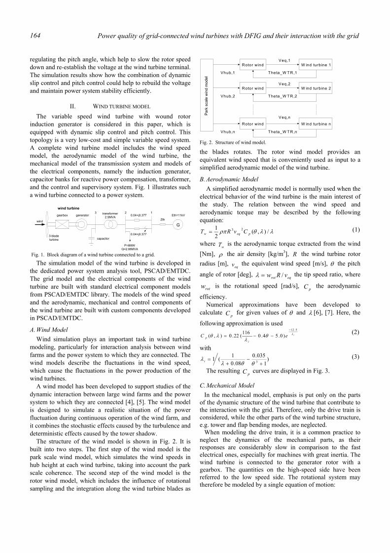
Power quality of grid-connected wind turbines with DFIG and their interaction with the grid 164
regulating the pitch angle, which help to slow the rotor speed down and re-establish the voltage at the wind turbine terminal. The simulation results show how the combination of dynamic slip control and pitch control could help to rebuild the voltage and maintain power system stability efficiently.
II. WIND TURBINE MODEL The variable speed wind turbine with wound rotor
induction generator is considered in this paper, which is equipped with dynamic slip control and pitch control. This topology is a very low-cost and simple variable speed system. A complete wind turbine model includes the wind speed model, the aerodynamic model of the wind turbine, the mechanical model of the transmission system and models of the electrical components, namely the induction generator, capacitor banks for reactive power compensation, transformer, and the control and supervisory system. Fig. 1 illustrates such a wind turbine connected to a power system.
The simulation model of the wind turbine is developed in the dedicated power system analysis tool, PSCAD/EMTDC. The grid model and the electrical components of the wind turbine are built with standard electrical component models from PSCAD/EMTDC library. The models of the wind speed and the aerodynamic, mechanical and control components of the wind turbine are built with custom components developed in PSCAD/EMTDC.
A. Wind Model Wind simulation plays an important task in wind turbine
modeling, particularly for interaction analysis between wind farms and the power system to which they are connected. The wind models describe the fluctuations in the wind speed, which cause the fluctuations in the power production of the wind turbines.
A wind model has been developed to support studies of the dynamic interaction between large wind farms and the power system to which they are connected [4], [5]. The wind model is designed to simulate a realistic situation of the power fluctuation during continuous operation of the wind farm, and it combines the stochastic effects caused by the turbulence and deterministic effects caused by the tower shadow.
The structure of the wind model is shown in Fig. 2. It is built into two steps. The first step of the wind model is the park scale wind model, which simulates the wind speeds in hub height at each wind turbine, taking into account the park scale coherence. The second step of the wind model is the rotor wind model, which includes the influence of rotational sampling and the integration along the wind turbine blades as
the blades rotates. The rotor wind model provides an equivalent wind speed that is conveniently used as input to a simplified aerodynamic model of the wind turbine.
B. Aerodynamic Model A simplified aerodynamic model is normally used when the
electrical behavior of the wind turbine is the main interest of the study. The relation between the wind speed and aerodynamic torque may be described by the following equation:
λλθρπ /),(21 23
peqw CvRT = (1)
where wT is the aerodynamic torque extracted from the wind
[Nm], ρ the air density [kg/m3], R the wind turbine rotor radius [m],
eqv the equivalent wind speed [m/s], θ the pitch
angle of rotor [deg], eqrot vRw /=λ the tip speed ratio, where
rotw is the rotational speed [rad/s], pC the aerodynamic
efficiency. Numerical approximations have been developed to
calculate pC for given values of θ and λ [6], [7]. Here, the
following approximation is used ieC
ip
λθλ
λθ5.12
)0.54.0116(22.0),(−
−−= (2)
with
)1
035.008.0
1(1 3 +−
+=
θθλλ i
(3)
The resulting pC curves are displayed in Fig. 3.
C. Mechanical Model In the mechanical model, emphasis is put only on the parts
of the dynamic structure of the wind turbine that contribute to the interaction with the grid. Therefore, only the drive train is considered, while the other parts of the wind turbine structure, e.g. tower and flap bending modes, are neglected.
When modeling the drive train, it is a common practice to neglect the dynamics of the mechanical parts, as their responses are considerably slow in comparison to the fast electrical ones, especially for machines with great inertia. The wind turbine is connected to the generator rotor with a gearbox. The quantities on the high-speed side have been referred to the low speed side. The rotational system may therefore be modeled by a single equation of motion:
gearbox generator
G
3-bladeturbine capacitor
transformer2.5MVA 0.04+j0.377
0.04+j0.377
ZthEth=11kV
P=6MWQ=2.88MVA
3 2 1
wind
wind turbine
Fig. 1. Block diagram of a wind turbine connected to a grid.
Park
sca
le w
ind
mod
el
Rotor w ind W ind turbine 1
Vhub,1
Veq,1
Theta_W TR,1
Rotor w ind W ind turbine 2
Vhub,2
Veq,2
Theta_W TR,2
Rotor w ind W ind turbine n
Vhub,n
Veq,n
Theta_W TR,n
Fig. 2. Structure of wind model.
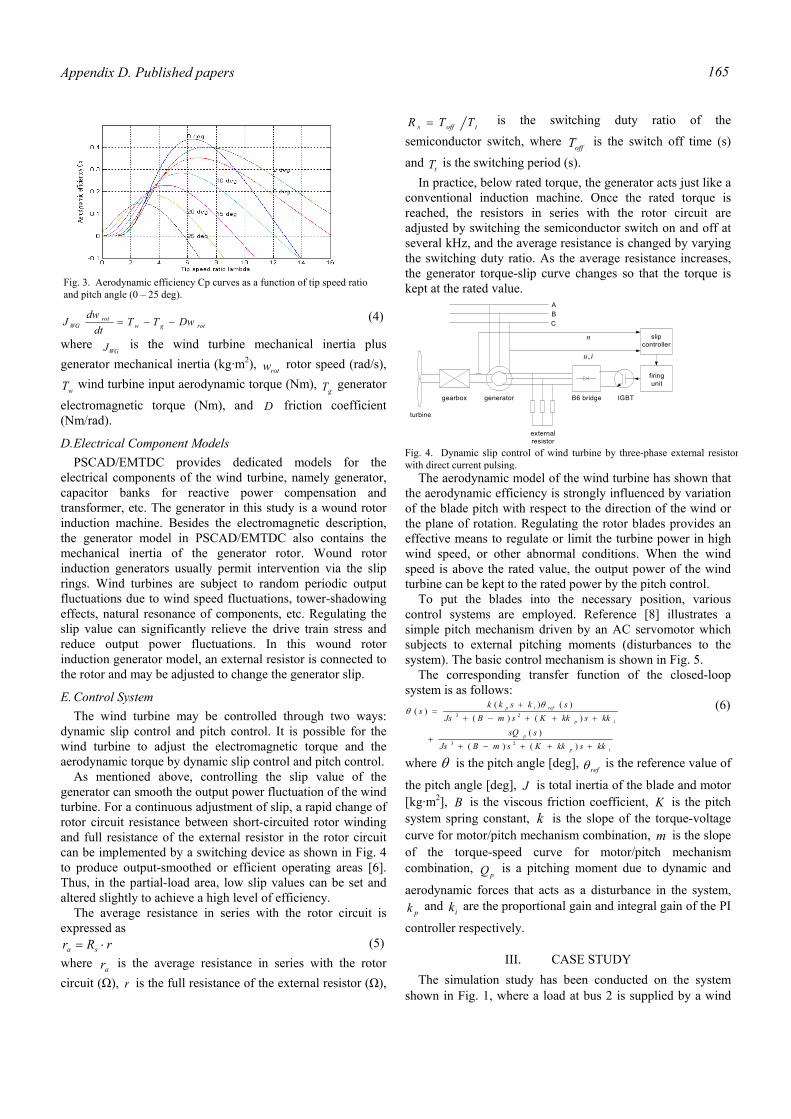
Appendix D. Published papers 165
rotgwrot
WG DwTTdt
dwJ −−= (4)
where WGJ is the wind turbine mechanical inertia plus
generator mechanical inertia (kg·m2), rotw rotor speed (rad/s),
wT wind turbine input aerodynamic torque (Nm), gT generator
electromagnetic torque (Nm), and D friction coefficient (Nm/rad).
D. Electrical Component Models PSCAD/EMTDC provides dedicated models for the
electrical components of the wind turbine, namely generator, capacitor banks for reactive power compensation and transformer, etc. The generator in this study is a wound rotor induction machine. Besides the electromagnetic description, the generator model in PSCAD/EMTDC also contains the mechanical inertia of the generator rotor. Wound rotor induction generators usually permit intervention via the slip rings. Wind turbines are subject to random periodic output fluctuations due to wind speed fluctuations, tower-shadowing effects, natural resonance of components, etc. Regulating the slip value can significantly relieve the drive train stress and reduce output power fluctuations. In this wound rotor induction generator model, an external resistor is connected to the rotor and may be adjusted to change the generator slip.
E. Control System The wind turbine may be controlled through two ways:
dynamic slip control and pitch control. It is possible for the wind turbine to adjust the electromagnetic torque and the aerodynamic torque by dynamic slip control and pitch control.
As mentioned above, controlling the slip value of the generator can smooth the output power fluctuation of the wind turbine. For a continuous adjustment of slip, a rapid change of rotor circuit resistance between short-circuited rotor winding and full resistance of the external resistor in the rotor circuit can be implemented by a switching device as shown in Fig. 4 to produce output-smoothed or efficient operating areas [6]. Thus, in the partial-load area, low slip values can be set and altered slightly to achieve a high level of efficiency.
The average resistance in series with the rotor circuit is expressed as
rRr sa ⋅= (5) where ar is the average resistance in series with the rotor circuit (Ω), r is the full resistance of the external resistor (Ω),
toffs TTR = is the switching duty ratio of the semiconductor switch, where offT is the switch off time (s)
and tT is the switching period (s). In practice, below rated torque, the generator acts just like a
conventional induction machine. Once the rated torque is reached, the resistors in series with the rotor circuit are adjusted by switching the semiconductor switch on and off at several kHz, and the average resistance is changed by varying the switching duty ratio. As the average resistance increases, the generator torque-slip curve changes so that the torque is kept at the rated value.
The aerodynamic model of the wind turbine has shown that the aerodynamic efficiency is strongly influenced by variation of the blade pitch with respect to the direction of the wind or the plane of rotation. Regulating the rotor blades provides an effective means to regulate or limit the turbine power in high wind speed, or other abnormal conditions. When the wind speed is above the rated value, the output power of the wind turbine can be kept to the rated power by the pitch control.
To put the blades into the necessary position, various control systems are employed. Reference [8] illustrates a simple pitch mechanism driven by an AC servomotor which subjects to external pitching moments (disturbances to the system). The basic control mechanism is shown in Fig. 5. The corresponding transfer function of the closed-loop system is as follows:
ip
p
ip
refip
kkskkKsmBJsssQ
kkskkKsmBJsskskk
s
+++−++
+++−+
+=
)()()(
)()()()(
)(
23
23
θθ (6)
where θ is the pitch angle [deg], refθ is the reference value of
the pitch angle [deg], J is total inertia of the blade and motor [kg·m2], B is the viscous friction coefficient, K is the pitch system spring constant, k is the slope of the torque-voltage curve for motor/pitch mechanism combination, m is the slope of the torque-speed curve for motor/pitch mechanism combination,
pQ is a pitching moment due to dynamic and
aerodynamic forces that acts as a disturbance in the system, pk and ik are the proportional gain and integral gain of the PI
controller respectively.
III. CASE STUDY The simulation study has been conducted on the system
shown in Fig. 1, where a load at bus 2 is supplied by a wind
Fig. 3. Aerodynamic efficiency Cp curves as a function of tip speed ratio and pitch angle (0 – 25 deg).
gearbox generator
turbine
firingunit
externalresistor
B6 bridge IGBT
A
CB
slipcontroller
n
iu,
Fig. 4. Dynamic slip control of wind turbine by three-phase external resistor with direct current pulsing.
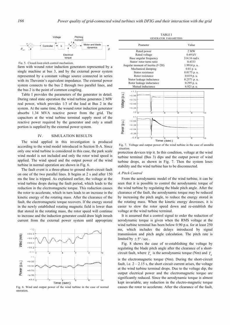
Power quality of grid-connected wind turbines with DFIG and their interaction with the grid 166
farm with wound rotor induction generators represented by a single machine at bus 3, and by the external power system represented by a constant voltage source connected in series with its Thevenin’s equivalent impedance. The external power system connects to the bus 2 through two parallel lines, and the bus 2 is the point of common coupling.
Table I provides the parameters of the generator in detail. During rated state operation the wind turbine generates 2 MW real power, which provides 1/3 of the load at Bus 2 in the system. At the same time, the wound rotor induction generator absorbs 1.34 MVA reactive power from the grid. The capacitors at the wind turbine terminal supply most of the reactive power required by the generator and only a small portion is supplied by the external power system.
IV. SIMULATION RESULTS The wind applied in this investigation is produced
according to the wind model introduced in Section II-A. Since only one wind turbine is considered in this case, the park scale wind model is not included and only the rotor wind speed is applied. The wind speed and the output power of the wind turbine in normal operation are shown in Fig. 6.
The fault event is a three-phase to ground short-circuit fault on one of the two parallel lines. It begins at 2 s and after 150 ms the line is tripped. As explained earlier, the voltage at the wind turbine drops during the fault period, which leads to the reduction in the electromagnetic torque. This reduction causes the rotor to accelerate, which in turn leads to an increase in the kinetic energy of the rotating mass. After the clearance of the fault, the electromagnetic torque recovers. If the energy stored in the newly established rotating magnetic field is lower than that stored in the rotating mass, the rotor speed will continue to increase and the induction generator could draw high inrush current from the external power system until appropriate
protection devices trip it. In this condition, voltage at the wind turbine terminal (Bus 3) dips and the output power of wind turbine drops, as shown in Fig. 7. Then the system loses stability and the wind turbine has to be disconnected.
A. Pitch Control From the aerodynamic model of the wind turbine, it can be
seen that it is possible to control the aerodynamic torque of the wind turbine by regulating the blade pitch angle. After the clearance of the fault, the aerodynamic torque may be reduced by increasing the pitch angle, to reduce the energy stored in the rotating mass. When the kinetic energy decreases, it is easier to slow the rotor speed down and re-establish the voltage at the wind turbine terminal.
It is assumed that a control signal to order the reduction of aerodynamic torque is given when the RMS voltage at the wind turbine terminal has been below 0.90 p.u. for at least 250 ms, which includes the delays introduced by signal transmission and pitch angle calculation. The pitch rate is limited by sec/5°± .
Fig. 8 shows the case of re-establishing the voltage by regulating the blade pitch angle after the clearance of a short-circuit fault, where wT is the aerodynamic torque (Nm) and gT
is the electromagnetic torque (Nm). During the short-circuit fault, i.e. 2 – 2.15 s, the short circuit current arises, the voltage at the wind turbine terminal drops. Due to the voltage dip, the output electrical power and the electromagnetic torque are significantly reduced. Since the aerodynamic torque is almost kept invariable, any reduction in the electro-magnetic torque causes the rotor to accelerate. After the clearance of the fault,
Controller k Motor and bladedynamics
Voltage
Electricaltorque
Pitchingmoment
++
+
-refθ θ
Fig. 5. Closed-loop pitch control mechanism.
TABLE I GENERATOR PARAMETERS
Prameter Value
Rated power 2 MW Rated voltage 0.69 kV
Base angular frequency 314.16 rad/s Stator/ rotor turns ratio 0.4333
Angular moment of inertia (J=2H) 1.9914 p. u. Mechanical damping 0.01 p. u.
Stator resistance 0.0175 p. u. Rotor resistance 0.019 p. u.
Stator leakage inductance 0.2571 p. u. Rotor leakage inductance 0.295 p. u.
Mutual inductance 6.921 p. u.
Fig. 6. Wind and output power of the wind turbine in the case of normaloperation.
Fig. 7. Voltage and output power of the wind turbine in the case of unstable situation.
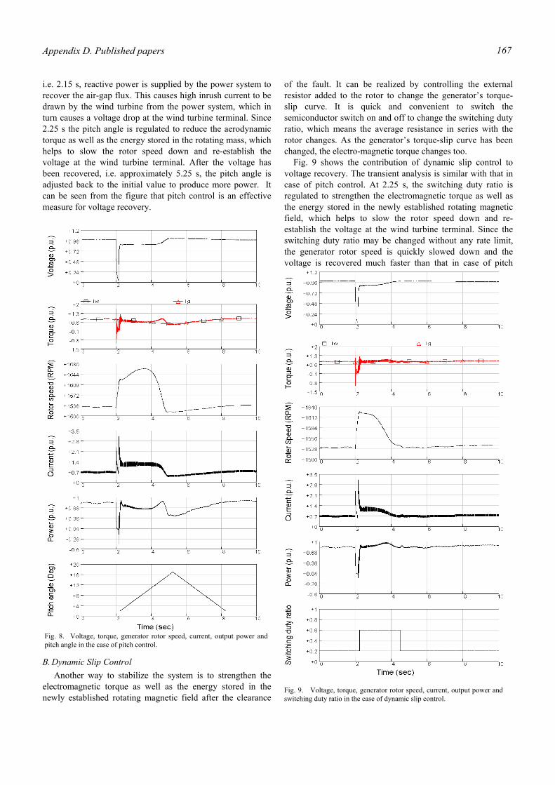
Appendix D. Published papers 167
i.e. 2.15 s, reactive power is supplied by the power system to recover the air-gap flux. This causes high inrush current to be drawn by the wind turbine from the power system, which in turn causes a voltage drop at the wind turbine terminal. Since 2.25 s the pitch angle is regulated to reduce the aerodynamic torque as well as the energy stored in the rotating mass, which helps to slow the rotor speed down and re-establish the voltage at the wind turbine terminal. After the voltage has been recovered, i.e. approximately 5.25 s, the pitch angle is adjusted back to the initial value to produce more power. It can be seen from the figure that pitch control is an effective measure for voltage recovery.
B. Dynamic Slip Control Another way to stabilize the system is to strengthen the
electromagnetic torque as well as the energy stored in the newly established rotating magnetic field after the clearance
of the fault. It can be realized by controlling the external resistor added to the rotor to change the generator’s torque-slip curve. It is quick and convenient to switch the semiconductor switch on and off to change the switching duty ratio, which means the average resistance in series with the rotor changes. As the generator’s torque-slip curve has been changed, the electro-magnetic torque changes too.
Fig. 9 shows the contribution of dynamic slip control to voltage recovery. The transient analysis is similar with that in case of pitch control. At 2.25 s, the switching duty ratio is regulated to strengthen the electromagnetic torque as well as the energy stored in the newly established rotating magnetic field, which helps to slow the rotor speed down and re-establish the voltage at the wind turbine terminal. Since the switching duty ratio may be changed without any rate limit, the generator rotor speed is quickly slowed down and the voltage is recovered much faster than that in case of pitch
Fig. 8. Voltage, torque, generator rotor speed, current, output power andpitch angle in the case of pitch control.
Fig. 9. Voltage, torque, generator rotor speed, current, output power andswitching duty ratio in the case of dynamic slip control.
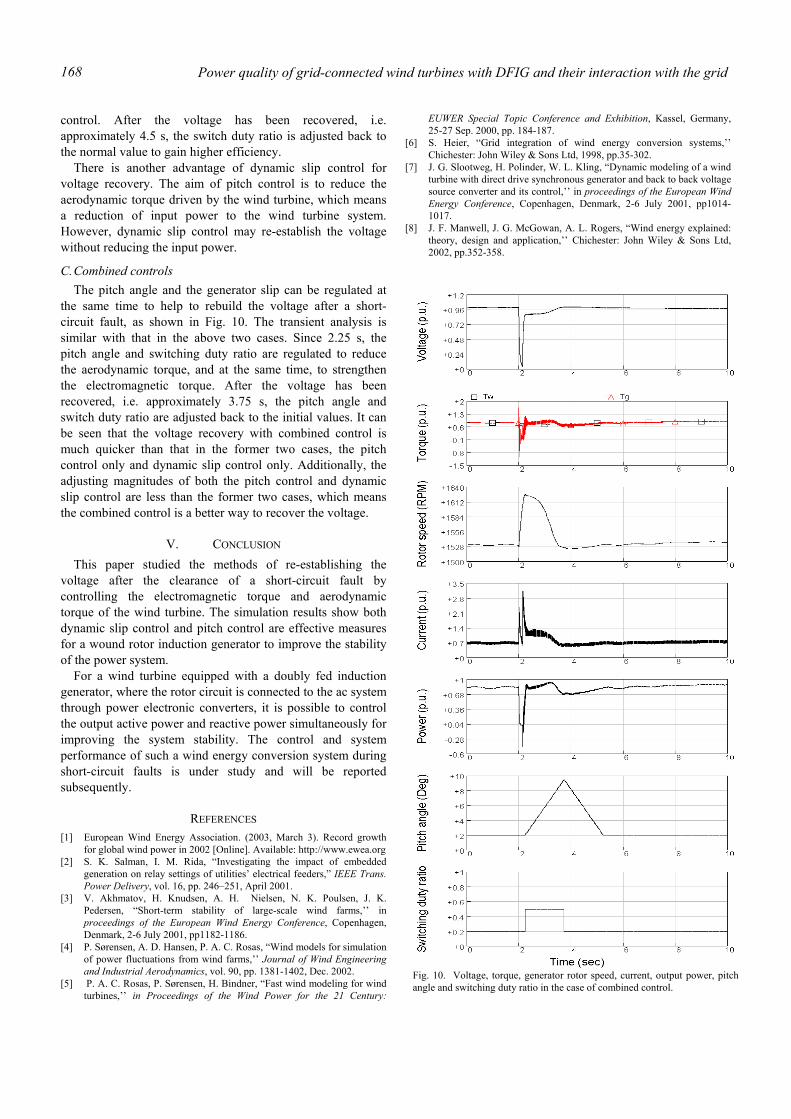
Power quality of grid-connected wind turbines with DFIG and their interaction with the grid 168
control. After the voltage has been recovered, i.e. approximately 4.5 s, the switch duty ratio is adjusted back to the normal value to gain higher efficiency.
There is another advantage of dynamic slip control for voltage recovery. The aim of pitch control is to reduce the aerodynamic torque driven by the wind turbine, which means a reduction of input power to the wind turbine system. However, dynamic slip control may re-establish the voltage without reducing the input power.
C. Combined controls The pitch angle and the generator slip can be regulated at
the same time to help to rebuild the voltage after a short-circuit fault, as shown in Fig. 10. The transient analysis is similar with that in the above two cases. Since 2.25 s, the pitch angle and switching duty ratio are regulated to reduce the aerodynamic torque, and at the same time, to strengthen the electromagnetic torque. After the voltage has been recovered, i.e. approximately 3.75 s, the pitch angle and switch duty ratio are adjusted back to the initial values. It can be seen that the voltage recovery with combined control is much quicker than that in the former two cases, the pitch control only and dynamic slip control only. Additionally, the adjusting magnitudes of both the pitch control and dynamic slip control are less than the former two cases, which means the combined control is a better way to recover the voltage.
V. CONCLUSION This paper studied the methods of re-establishing the
voltage after the clearance of a short-circuit fault by controlling the electromagnetic torque and aerodynamic torque of the wind turbine. The simulation results show both dynamic slip control and pitch control are effective measures for a wound rotor induction generator to improve the stability of the power system.
For a wind turbine equipped with a doubly fed induction generator, where the rotor circuit is connected to the ac system through power electronic converters, it is possible to control the output active power and reactive power simultaneously for improving the system stability. The control and system performance of such a wind energy conversion system during short-circuit faults is under study and will be reported subsequently.
REFERENCES [1] European Wind Energy Association. (2003, March 3). Record growth
for global wind power in 2002 [Online]. Available: http://www.ewea.org [2] S. K. Salman, I. M. Rida, “Investigating the impact of embedded
generation on relay settings of utilities’ electrical feeders,” IEEE Trans. Power Delivery, vol. 16, pp. 246–251, April 2001.
[3] V. Akhmatov, H. Knudsen, A. H. Nielsen, N. K. Poulsen, J. K. Pedersen, “Short-term stability of large-scale wind farms,’’ in proceedings of the European Wind Energy Conference, Copenhagen, Denmark, 2-6 July 2001, pp1182-1186.
[4] P. Sørensen, A. D. Hansen, P. A. C. Rosas, “Wind models for simulation of power fluctuations from wind farms,’’ Journal of Wind Engineering and Industrial Aerodynamics, vol. 90, pp. 1381-1402, Dec. 2002.
[5] P. A. C. Rosas, P. Sørensen, H. Bindner, “Fast wind modeling for wind turbines,’’ in Proceedings of the Wind Power for the 21 Century:
EUWER Special Topic Conference and Exhibition, Kassel, Germany, 25-27 Sep. 2000, pp. 184-187.
[6] S. Heier, “Grid integration of wind energy conversion systems,’’ Chichester: John Wiley & Sons Ltd, 1998, pp.35-302.
[7] J. G. Slootweg, H. Polinder, W. L. Kling, “Dynamic modeling of a wind turbine with direct drive synchronous generator and back to back voltage source converter and its control,’’ in proceedings of the European Wind Energy Conference, Copenhagen, Denmark, 2-6 July 2001, pp1014-1017.
[8] J. F. Manwell, J. G. McGowan, A. L. Rogers, “Wind energy explained: theory, design and application,’’ Chichester: John Wiley & Sons Ltd, 2002, pp.352-358.
Fig. 10. Voltage, torque, generator rotor speed, current, output power, pitch angle and switching duty ratio in the case of combined control.
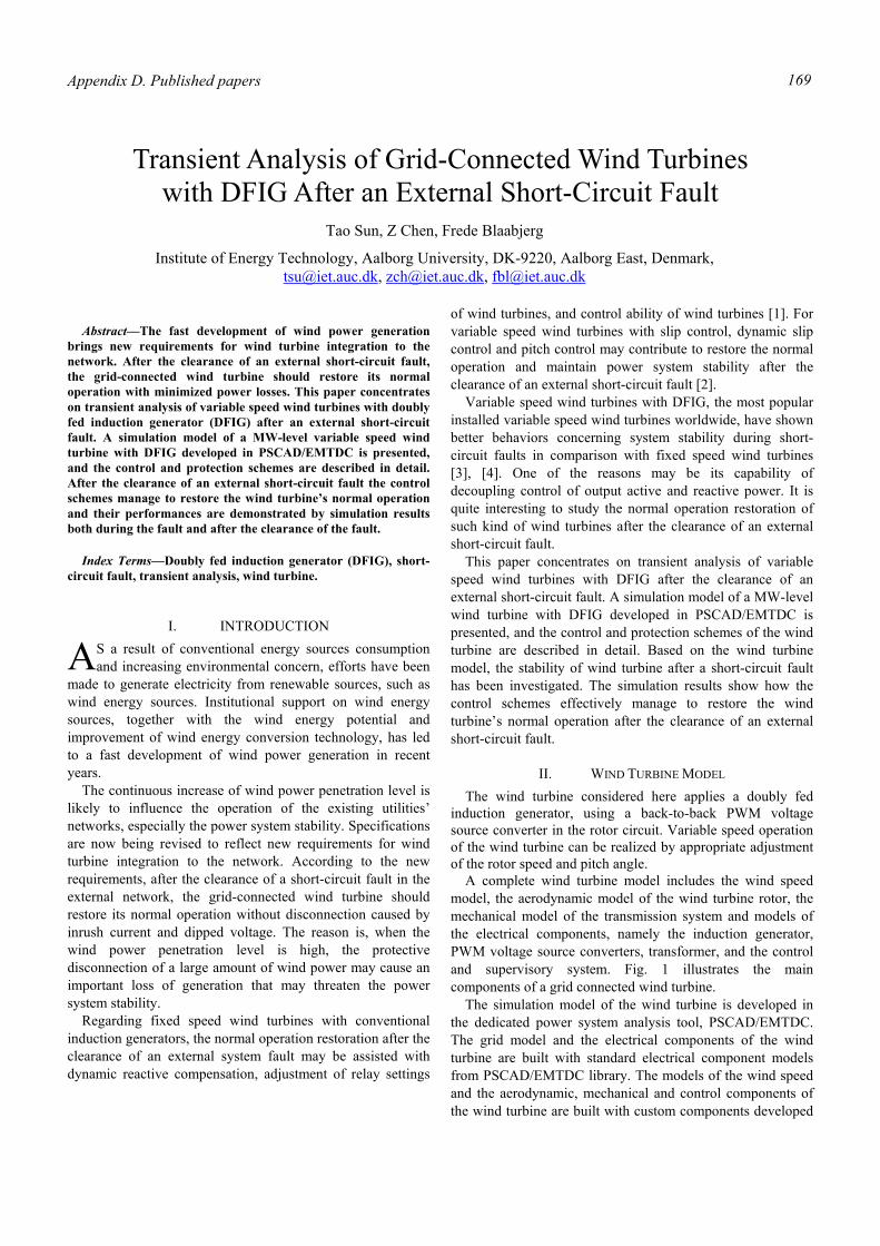
Appendix D. Published papers 169
Abstract—The fast development of wind power generation
brings new requirements for wind turbine integration to the network. After the clearance of an external short-circuit fault, the grid-connected wind turbine should restore its normal operation with minimized power losses. This paper concentrates on transient analysis of variable speed wind turbines with doubly fed induction generator (DFIG) after an external short-circuit fault. A simulation model of a MW-level variable speed wind turbine with DFIG developed in PSCAD/EMTDC is presented, and the control and protection schemes are described in detail. After the clearance of an external short-circuit fault the control schemes manage to restore the wind turbine’s normal operation and their performances are demonstrated by simulation results both during the fault and after the clearance of the fault.
Index Terms—Doubly fed induction generator (DFIG), short-circuit fault, transient analysis, wind turbine.
I. INTRODUCTION S a result of conventional energy sources consumption and increasing environmental concern, efforts have been
made to generate electricity from renewable sources, such as wind energy sources. Institutional support on wind energy sources, together with the wind energy potential and improvement of wind energy conversion technology, has led to a fast development of wind power generation in recent years.
The continuous increase of wind power penetration level is likely to influence the operation of the existing utilities’ networks, especially the power system stability. Specifications are now being revised to reflect new requirements for wind turbine integration to the network. According to the new requirements, after the clearance of a short-circuit fault in the external network, the grid-connected wind turbine should restore its normal operation without disconnection caused by inrush current and dipped voltage. The reason is, when the wind power penetration level is high, the protective disconnection of a large amount of wind power may cause an important loss of generation that may threaten the power system stability.
Regarding fixed speed wind turbines with conventional induction generators, the normal operation restoration after the clearance of an external system fault may be assisted with dynamic reactive compensation, adjustment of relay settings
of wind turbines, and control ability of wind turbines [1]. For variable speed wind turbines with slip control, dynamic slip control and pitch control may contribute to restore the normal operation and maintain power system stability after the clearance of an external short-circuit fault [2].
Variable speed wind turbines with DFIG, the most popular installed variable speed wind turbines worldwide, have shown better behaviors concerning system stability during short-circuit faults in comparison with fixed speed wind turbines [3], [4]. One of the reasons may be its capability of decoupling control of output active and reactive power. It is quite interesting to study the normal operation restoration of such kind of wind turbines after the clearance of an external short-circuit fault.
This paper concentrates on transient analysis of variable speed wind turbines with DFIG after the clearance of an external short-circuit fault. A simulation model of a MW-level wind turbine with DFIG developed in PSCAD/EMTDC is presented, and the control and protection schemes of the wind turbine are described in detail. Based on the wind turbine model, the stability of wind turbine after a short-circuit fault has been investigated. The simulation results show how the control schemes effectively manage to restore the wind turbine’s normal operation after the clearance of an external short-circuit fault.
II. WIND TURBINE MODEL The wind turbine considered here applies a doubly fed
induction generator, using a back-to-back PWM voltage source converter in the rotor circuit. Variable speed operation of the wind turbine can be realized by appropriate adjustment of the rotor speed and pitch angle.
A complete wind turbine model includes the wind speed model, the aerodynamic model of the wind turbine rotor, the mechanical model of the transmission system and models of the electrical components, namely the induction generator, PWM voltage source converters, transformer, and the control and supervisory system. Fig. 1 illustrates the main components of a grid connected wind turbine.
The simulation model of the wind turbine is developed in the dedicated power system analysis tool, PSCAD/EMTDC. The grid model and the electrical components of the wind turbine are built with standard electrical component models from PSCAD/EMTDC library. The models of the wind speed and the aerodynamic, mechanical and control components of the wind turbine are built with custom components developed
Transient Analysis of Grid-Connected Wind Turbines with DFIG After an External Short-Circuit Fault
Tao Sun, Z Chen, Frede Blaabjerg
Institute of Energy Technology, Aalborg University, DK-9220, Aalborg East, Denmark, [email protected], [email protected], [email protected]
A
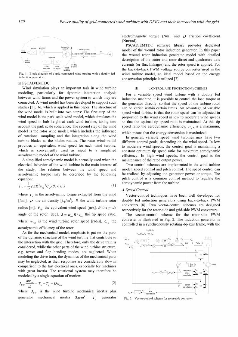
Power quality of grid-connected wind turbines with DFIG and their interaction with the grid 170
in PSCAD/EMTDC. Wind simulation plays an important task in wind turbine
modeling, particularly for dynamic interaction analysis between wind farms and the power system to which they are connected. A wind model has been developed to support such studies [5], [6], which is applied in this paper. The structure of the wind model is built into two steps: The first step of the wind model is the park scale wind model, which simulates the wind speed in hub height at each wind turbine, taking into account the park scale coherence; The second step of the wind model is the rotor wind model, which includes the influence of rotational sampling and the integration along the wind turbine blades as the blades rotates. The rotor wind model provides an equivalent wind speed for each wind turbine, which is conveniently used as input to a simplified aerodynamic model of the wind turbine.
A simplified aerodynamic model is normally used when the electrical behavior of the wind turbine is the main interest of the study. The relation between the wind speed and aerodynamic torque may be described by the following equation:
λλθρπ /),(21 23
peqw CvRT = (1)
where wT is the aerodynamic torque extracted from the wind [Nm], ρ the air density [kg/m3], R the wind turbine rotor
radius [m], eqv the equivalent wind speed [m/s], θ the pitch
angle of the rotor [deg], eqrot vRw /=λ the tip speed ratio,
where rotw is the wind turbine rotor speed [rad/s], pC the
aerodynamic efficiency of the rotor. As for the mechanical model, emphasis is put on the parts
of the dynamic structure of the wind turbine that contribute to the interaction with the grid. Therefore, only the drive train is considered, while the other parts of the wind turbine structure, e.g. tower and flap bending modes, are neglected. When modeling the drive train, the dynamics of the mechanical parts may be neglected, as their responses are considerably slow in comparison to the fast electrical ones, especially for machines with great inertia. The rotational system may therefore be modeled by a single equation of motion:
rotgwrot
WG DwTTdt
dwJ −−= (2)
where WGJ is the wind turbine mechanical inertia plus generator mechanical inertia (kg·m2), gT generator
electromagnetic torque (Nm), and D friction coefficient (Nm/rad).
PSCAD/EMTDC software library provides dedicated model of the wound rotor induction generator. In this paper the wound rotor induction generator model with detailed description of the stator and rotor direct and quadrature axis currents (or flux linkages) and the rotor speed is applied. For the back-to-back PWM voltage source converter used in the wind turbine model, an ideal model based on the energy conservation principle is utilized [7].
III. CONTROL AND PROTECTION SCHEMES For a variable speed wind turbine with a doubly fed
induction machine, it is possible to control the load torque at the generator directly, so that the speed of the turbine rotor can be varied within certain limits. An advantage of variable speed wind turbine is that the rotor speed can be adjusted in proportion to the wind speed in low to moderate wind speeds so that the optimal tip speed ratio is maintained. At this tip speed ratio the aerodynamic efficiency,
pC , is a maximum,
which means that the energy conversion is maximized. In general, variable speed wind turbines may have two
different control goals, depending on the wind speed. In low to moderate wind speeds, the control goal is maintaining a constant optimum tip speed ratio for maximum aerodynamic efficiency. In high wind speeds, the control goal is the maintenance of the rated output power.
Two control schemes are implemented in the wind turbine model: speed control and pitch control. The speed control can be realized by adjusting the generator power or torque. The pitch control is a common control method to regulate the aerodynamic power from the turbine.
A. Speed Control Vector-control techniques have been well developed for
doubly fed induction generators using back-to-back PWM converters [8]. Two vector-control schemes are designed respectively for the rotor-side and grid-side PWM converters.
The vector-control scheme for the rotor-side PWM converter is illustrated in Fig. 2. The induction generator is controlled in a synchronously rotating dq-axis frame, with the
3-bladeturbine
gearboxtransformer
2.5MVA 2wind
generator
capacitor
PWMconverter
PWMconverter wind
turbine
P=4MWQ=2MVA
G
1Zth
0.6764+j1.3527
0.3382+j0.6764 0.3382+j0.6764
Fig. 1. Block diagram of a grid connected wind turbine with a doubly fedinduction generator.
PWM2/3
3/2stator flux
anglecalculation
PI
PI
mL/1
PI+
-
+
-
swsiαβ
dri
dsψ
+ -
-
+
+
)( drrmsmmslip iLiLw σ+
*qru
*dru
++
*abcru
sθ
qrrslip iLw σ
abcri
msi
DFIG
suαβ
rθ
3/2qri
abcsiabcsu
3/2dqsidqsu
powercalculationsQ
sP
dtd /
∫dt
+
rw
slipw
PI+
-dru′
qru′
*dri
*qrirefsP _
refsQ _
-
-
fluxcalculation dsi
Fig. 2. Vector-control scheme for rotor-side converter.
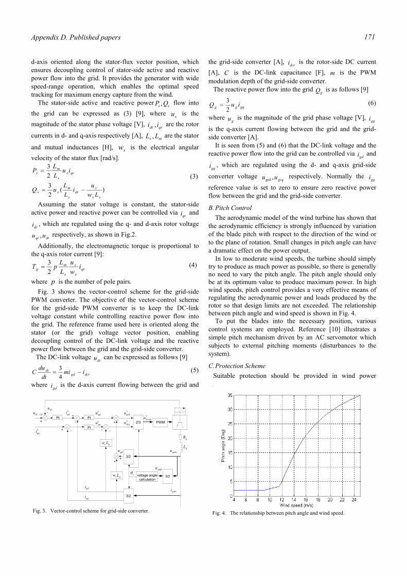
Appendix D. Published papers 171
d-axis oriented along the stator-flux vector position, which ensures decoupling control of stator-side active and reactive power flow into the grid. It provides the generator with wide speed-range operation, which enables the optimal speed tracking for maximum energy capture from the wind.
The stator-side active and reactive power ss QP , flow into the grid can be expressed as (3) [9], where su is the magnitude of the stator phase voltage [V], qrdr ii , are the rotor
currents in d- and q-axis respectively [A], ms LL , are the stator
and mutual inductances [H], sw is the electrical angular velocity of the stator flux [rad/s].
)(2323
ss
sdr
s
mss
qrss
ms
Lwui
LLuQ
iuLLP
−=
= (3)
Assuming the stator voltage is constant, the stator-side active power and reactive power can be controlled via
qri and
dri , which are regulated using the q- and d-axis rotor voltage
drqr uu , respectively, as shown in Fig.2.
Additionally, the electromagnetic torque is proportional to the q-axis rotor current [9]:
qrs
s
s
mg i
wu
LLpT
23
= (4)
where p is the number of pole pairs. Fig. 3 shows the vector-control scheme for the grid-side PWM converter. The objective of the vector-control scheme for the grid-side PWM converter is to keep the DC-link voltage constant while controlling reactive power flow into the grid. The reference frame used here is oriented along the stator (or the grid) voltage vector position, enabling decoupling control of the DC-link voltage and the reactive power flow between the grid and the grid-side converter.
The DC-link voltage dcu can be expressed as follows [9]
dcrgddc imi
dtdu
C −=43 (5)
where gdi is the d-axis current flowing between the grid and
the grid-side converter [A], dcri is the rotor-side DC current [A], C is the DC-link capacitance [F], m is the PWM modulation depth of the grid-side converter.
The reactive power flow into the grid gQ is as follows [9]
gqgg iuQ23
= (6)
where gu is the magnitude of the grid phase voltage [V],
gqi
is the q-axis current flowing between the grid and the grid-side converter [A]. It is seen from (5) and (6) that the DC-link voltage and the reactive power flow into the grid can be controlled via
gdi and
gqi , which are regulated using the d- and q-axis grid-side
converter voltage gcquu ,gcd
respectively. Normally the gqi
reference value is set to zero to ensure zero reactive power flow between the grid and the grid-side converter.
B. Pitch Control The aerodynamic model of the wind turbine has shown that
the aerodynamic efficiency is strongly influenced by variation of the blade pitch with respect to the direction of the wind or to the plane of rotation. Small changes in pitch angle can have a dramatic effect on the power output.
In low to moderate wind speeds, the turbine should simply try to produce as much power as possible, so there is generally no need to vary the pitch angle. The pitch angle should only be at its optimum value to produce maximum power. In high wind speeds, pitch control provides a very effective means of regulating the aerodynamic power and loads produced by the rotor so that design limits are not exceeded. The relationship between pitch angle and wind speed is shown in Fig. 4.
To put the blades into the necessary position, various control systems are employed. Reference [10] illustrates a simple pitch mechanism driven by an AC servomotor which subjects to external pitching moments (disturbances to the system).
C. Protection Scheme Suitable protection should be provided in wind power
Fig. 4. The relationship between pitch angle and wind speed.
PWM2/3
3/2voltage anglecalculation
3/2
3/2
PI
PI
ge Lw
ge Lw
PIrefdcu _
dcu
+
- *gdi
+
-
gdu′
gdi
gqi
*gqi
gqu′
+ -
-
+
++
gdu
*gcdu
*gcqu
- -
*gcabcu
gL
gR
eθ
gabcu
gabci
αβgu
Fig. 3. Vector-control scheme for grid-side converter.
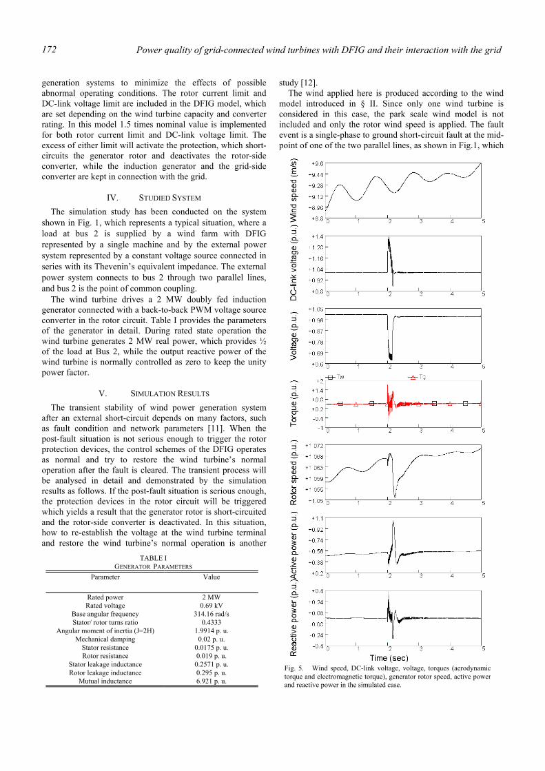
Power quality of grid-connected wind turbines with DFIG and their interaction with the grid 172
generation systems to minimize the effects of possible abnormal operating conditions. The rotor current limit and DC-link voltage limit are included in the DFIG model, which are set depending on the wind turbine capacity and converter rating. In this model 1.5 times nominal value is implemented for both rotor current limit and DC-link voltage limit. The excess of either limit will activate the protection, which short-circuits the generator rotor and deactivates the rotor-side converter, while the induction generator and the grid-side converter are kept in connection with the grid.
IV. STUDIED SYSTEM The simulation study has been conducted on the system
shown in Fig. 1, which represents a typical situation, where a load at bus 2 is supplied by a wind farm with DFIG represented by a single machine and by the external power system represented by a constant voltage source connected in series with its Thevenin’s equivalent impedance. The external power system connects to bus 2 through two parallel lines, and bus 2 is the point of common coupling.
The wind turbine drives a 2 MW doubly fed induction generator connected with a back-to-back PWM voltage source converter in the rotor circuit. Table I provides the parameters of the generator in detail. During rated state operation the wind turbine generates 2 MW real power, which provides ½ of the load at Bus 2, while the output reactive power of the wind turbine is normally controlled as zero to keep the unity power factor.
V. SIMULATION RESULTS The transient stability of wind power generation system
after an external short-circuit depends on many factors, such as fault condition and network parameters [11]. When the post-fault situation is not serious enough to trigger the rotor protection devices, the control schemes of the DFIG operates as normal and try to restore the wind turbine’s normal operation after the fault is cleared. The transient process will be analysed in detail and demonstrated by the simulation results as follows. If the post-fault situation is serious enough, the protection devices in the rotor circuit will be triggered which yields a result that the generator rotor is short-circuited and the rotor-side converter is deactivated. In this situation, how to re-establish the voltage at the wind turbine terminal and restore the wind turbine’s normal operation is another
study [12]. The wind applied here is produced according to the wind
model introduced in § II. Since only one wind turbine is considered in this case, the park scale wind model is not included and only the rotor wind speed is applied. The fault event is a single-phase to ground short-circuit fault at the mid-point of one of the two parallel lines, as shown in Fig.1, which
TABLE I GENERATOR PARAMETERS
Parameter Value
Rated power 2 MW Rated voltage 0.69 kV
Base angular frequency 314.16 rad/s Stator/ rotor turns ratio 0.4333
Angular moment of inertia (J=2H) 1.9914 p. u. Mechanical damping 0.02 p. u.
Stator resistance 0.0175 p. u. Rotor resistance 0.019 p. u.
Stator leakage inductance 0.2571 p. u. Rotor leakage inductance 0.295 p. u.
Mutual inductance 6.921 p. u.
Fig. 5. Wind speed, DC-link voltage, voltage, torques (aerodynamictorque and electromagnetic torque), generator rotor speed, active powerand reactive power in the simulated case.
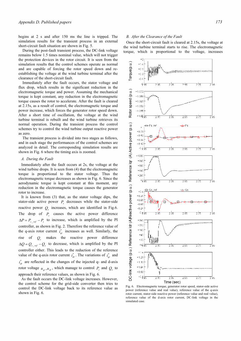
Appendix D. Published papers 173
begins at 2 s and after 150 ms the line is tripped. The simulation results for the transient process in an external short-circuit fault situation are shown in Fig. 5.
During the post-fault transient process, the DC-link voltage remains below 1.5 times nominal value, which will not trigger the protection devices in the rotor circuit. It is seen from the simulation results that the control schemes operate as normal and are capable of forcing the rotor speed down and re-establishing the voltage at the wind turbine terminal after the clearance of the short-circuit fault.
Immediately after the fault occurs, the stator voltage and flux drop, which results in the significant reduction in the electromagnetic torque and power. Assuming the mechanical torque is kept constant, any reduction in the electromagnetic torque causes the rotor to accelerate. After the fault is cleared at 2.15s, as a result of control, the electromagnetic torque and power increase, which forces the generator rotor speed down. After a short time of oscillation, the voltage at the wind turbine terminal is rebuilt and the wind turbine retrieves its normal operation. During the transient process the control schemes try to control the wind turbine output reactive power as zero.
The transient process is divided into two stages as follows, and in each stage the performances of the control schemes are analyzed in detail. The corresponding simulation results are shown in Fig. 6 where the timing axis is zoomed.
A. During the Fault Immediately after the fault occurs at 2s, the voltage at the
wind turbine drops. It is seen from (4) that the electromagnetic torque is proportional to the stator voltage. Thus the electromagnetic torque decreases as shown in Fig. 6. Since the aerodynamic torque is kept constant at this moment, any reduction in the electromagnetic torque causes the generator rotor to increase.
It is known from (3) that, as the stator voltage dips, the stator-side active power sP decreases while the stator-side reactive power sQ increases, which are identified in Fig.6. The drop of sP causes the active power difference
srefs PPP −=∆ _ to increase, which is amplified by the PI
controller, as shown in Fig. 2. Therefore the reference value of the q-axis rotor current *
qri increases as well. Similarly, the
rise of sQ makes the reactive power difference
srefs QQQ −=∆ _ to decrease, which is amplified by the PI
controller either. This leads to the reduction of the reference value of the q-axis rotor current *
dri . The variations of *qri and
*dri are reflected in the changes of the injected q- and d-axis
rotor voltage drqr uu , , which manage to control sP and sQ to
approach their reference values, as shown in Fig. 6. As the fault occurs the DC-link voltage increases. However,
the control scheme for the grid-side converter then tries to control the DC-link voltage back to its reference value as shown in Fig. 6.
B. After the Clearance of the Fault Once the short-circuit fault is cleared at 2.15s, the voltage at
the wind turbine terminal starts to rise. The electromagnetic torque, which is proportional to the voltage, increases
Fig. 6. Electromagnetic torque, generator rotor speed, stator-side active power (reference value and real value), reference value of the q-axis rotor current, stator-side reactive power (reference value and real value), reference value of the d-axis rotor current, DC-link voltage in the simulated case.

Power quality of grid-connected wind turbines with DFIG and their interaction with the grid 174
instantly which results in the generator rotor speed dips. As a result of the voltage increase, the stator-side active
power sP increases while the stator-side reactive power sQ decreases. Similar as the analysis mentioned above, it is learned that as the voltage rises *
qri decreases while *dri
increases. The variations of *qri and *
dri are reflected in the
changes of the injected q- and d-axis rotor voltage drqr uu , ,
which manage to control sP and sQ to approach their reference values. It is seen from Fig. 6 that the wind turbine restores its normal operation after a short-time oscillation.
VI. CONCLUSION A simulation model of a MW-level wind turbine with DFIG
developed in PSCAD/EMTDC is presented, and the control and protection schemes of the wind turbine are described in detail. Based on the wind turbine model, the transient stability of the wind turbine after a short-circuit fault has been investigated. When the post-fault situation is not serious enough to trigger the protection devices in the rotor circuit, the control schemes of the DFIG operates as normal and are capable of forcing the rotor speed down and re-establishing the voltage at the wind turbine terminal after the short-circuit fault is cleared. The simulation results demonstrate how the control schemes effectively manage to restore the wind turbine’s normal operation after the clearance of an external short-circuit fault.
REFERENCES [1] V. Akhmatov, H. Knudsen, A. H. Nielsen, N. K. Poulsen, J. K.
Pedersen, “Short-term stability of large-scale wind farms,’’ in Proceedings of the European Wind Energy Conference, Copenhagen, Denmark, 2-6 July 2001, pp. 1182-1186.
[2] T. Sun, Z. Chen, F. Blaabjerg, “Voltage recovery of grid-connected wind turbines after a short-circuit fault,’’ in Proceedings of the 29th Annual Conference of the IEEE Industrial Electronics Society (IECON 2003), Roanoke, Virginia, USA, 2-6 Nov. 2003, pp. 2723-2728.
[3] L. Holdsworth, X.G. Wu, J.B. Ekanayake, N. Jenkins, “Comparison of fixed speed and doubly-fed induction wind turbines during power system disturbances,’’ IEE Proc. Gener. Transm. Distrib., vol. 150, no. 3, pp. 343-352, May 2003.
[4] J. Usaola, P. Ledesma, “Dynamic incidence of wind turbines in networks with high wind penetration,’’ in Proceedings of 2001 IEEE Power Engineering Society Summer Meeting, Vancouver, Canada, 15-19 July 2001, vol. 2, pp. 755-760.
[5] P. Sørensen, A. D. Hansen, P. A. C. Rosas, “Wind models for simulation of power fluctuations from wind farms,’’ Journal of Wind Engineering and Industrial Aerodynamics, vol. 90, pp. 1381-1402, Dec. 2002.
[6] P. A. C. Rosas, P. Sørensen, H. Bindner, “Fast wind modeling for wind turbines,’’ in Proceedings of the Wind Power for the 21 Century: EUWER Special Topic Conference and Exhibition, Kassel, Germany, 25-27 Sep. 2000, pp. 184-187.
[7] P. Giroux, G. Sybille, H. Le-Huy, ‘‘Modeling and simulation of a distribution STATCOM using simulink’s power system blockset,’’ in proceeding of the 27th Annual Conference of the IEEE Industrial Electronics Society, Denver, USA, 29 Nov- 2 Dec 2001, vol. 2, pp. 990-994.
[8] R. Pena, J. C. Clare, G. M. Asher, ‘‘Doubly fed induction generator using back-to-back PWM converters and its application to variable-speed wind-energy generation,’’ IEE Proc. Electr. Power Appl., vol. 143, no. 3, pp. 231-241, May 1996.
[9] T. Sun, “Power quality of grid connected wind turbines and their interaction with the grid,’’ Institute of Energy Technology, Aalborg University, August 2003, unpublished.
[10] J. F. Manwell, J. G. McGowan, A. L. Rogers, “Wind energy explained: theory, design and application,’’ Chichester: John Wiley & Sons Ltd, 2002, pp.352-358.
[11] L. Holdsworth, N. Jenkins, G. Strbac, “Electrical stability of large, offshore wind farms,’’ in Proceedings of the Seventh International Conference on AC-DC Power Transmission, Manchester, UK, 28-30 Nov. 2001, pp156-161.
[12] T. Sun, Z. Chen, F. Blaabjerg, “Voltage recovery of grid-connected wind turbines with DFIG after a short-circuit fault,’’ in Proceedings of the 35th IEEE Power Electronics Specialists Conference (PESC 2004), Aachen, Germany, 20-25 June 2004, submitted for publication.
Appendix D. Published papers 175
Keywords: Doubly fed induction generator, flicker, STATCOM, wind turbine.
Abstract
Grid connected wind turbines may produce flicker during continuous operation. In this paper flicker emission of grid connected wind turbines with doubly fed induction generators is investigated during continuous operation. A STATCOM using PWM voltage source converter (VSC) is connected in shunt to the point of common coupling (PCC) to relieve the flicker produced by grid connected wind turbines and the corresponding control scheme is described in detail. Simulation results show that STATCOM is an effective measure to mitigate the flicker during continuous operation of grid connected wind turbines.
1 Introduction
In recent years wind power generation has experienced a very fast development in the whole world. As the wind power penetration into the grid is increasing quickly, the influence of wind turbines on the power quality is becoming an important issue. One of the important power quality aspects is flicker. Flicker is induced by voltage fluctuations, which are caused by load flow changes in the grid. Grid connected wind turbines may have considerable fluctuations in output power, which depend on the wind power generation technology applied. The flicker emission produced by grid connected wind turbines during continuous operation is mainly caused by fluctuations in the output power due to wind speed variations, the wind gradient and the tower shadow effect [1]. Regarding to variable speed wind turbines, which have the ability to reduce power fluctuations, flicker emission is quite different from that generated by fixed speed wind turbines. Variable speed operation of the rotor has the advantage that the faster power variations are not transmitted to the grid but are smoothed by the flywheel action of the rotor. Variable speed wind turbines with doubly fed induction generators, the most popular installed variable speed wind turbines worldwide, are the main research interest here [2]. Even though variable speed wind turbines have good performance with respect to flicker emission, flicker mitigation becomes necessary as the wind power penetration level increases. Flicker mitigation can be realized by appropriate reactive shunt compensation. The most commonly used device for flicker mitigation is the Static Var
Compensator (SVC). However, the STATCOM has received much more attention recently. Compared with the SVC, the STATCOM has many advantages, such as overall superior functional characteristics, better performance, faster response, smaller size, cost reduction, and capable of providing both active and reactive power [3]. Some research results also showed that the STATCOM is superior to the SVC with respect to flicker mitigation [4,5]. The STATCOM, consisting of a voltage source converter, uses advanced power switches to provide fast response and flexible voltage control for power quality improvement, which is suitable to application with rapidly fluctuating loads. Using high frequency PWM, the converter will create smooth current with low harmonic content. In this paper, flicker emission of grid connected wind turbines with doubly fed induction generators is investigated during continuous operation. The factors that affect flicker emission of wind turbines, such as wind speed, turbulence intensity, short circuit capacity and grid impedance angle, are analyzed. A simplified model of STATCOM using PWM voltage source converter is developed and the corresponding control scheme is described in detail. Simulation results prove that STATCOM is an effective means to mitigate the flicker level during continuous operation of grid connected wind turbines.
2 Flicker emission of wind turbine
2.1 Modelling and Control of Wind Turbine
The wind turbine considered here applies a doubly fed induction generator, using back-to-back PWM voltage source converters in the rotor circuit. A complete wind turbine model includes the wind speed model, the aerodynamic model of the wind turbine, the mechanical model of the transmission system and models of the electrical components, namely the induction generator, PWM voltage source converters, transformer, the control and the supervisory system. Fig. 1 illustrates the main components of a grid connected wind turbine. The simulation model of the wind turbine is developed in the dedicated power system analysis tool, PSCAD/EMTDC.
Two control schemes are implemented in the wind turbine model: speed control and pitch control. The speed control can be realized by adjusting the generator power or torque. The pitch control is a common control method to regulate the aerodynamic power from the turbine.
T. Sun*†‡, Z. Chen‡, F. Blaabjerg‡
*North China Electric Power University, Baoding, 071003 China †China Electric Power Research Institute, Beijing, 100085 China
‡Aalborg University, DK-9220 Aalborg, Denmark E-mail: [email protected], Fax: +45 9815 1411
FLICKER MITIGATION OF GRID CONNECTED WIND TURBINES USING STATCOM
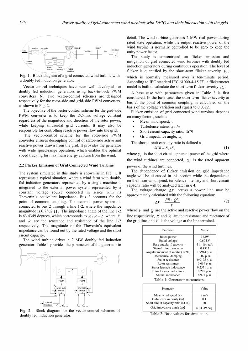
Power quality of grid-connected wind turbines with DFIG and their interaction with the grid 176
Vector-control techniques have been well developed for doubly fed induction generators using back-to-back PWM converters [6]. Two vector-control schemes are designed respectively for the rotor-side and grid-side PWM converters, as shown in Fig. 2.
The objective of the vector-control scheme for the grid-side PWM converter is to keep the DC-link voltage constant regardless of the magnitude and direction of the rotor power, while keeping sinusoidal grid currents. It may also be responsible for controlling reactive power flow into the grid.
The vector-control scheme for the rotor-side PWM converter ensures decoupling control of stator-side active and reactive power drawn from the grid. It provides the generator with wide speed-range operation, which enables the optimal speed tracking for maximum energy capture from the wind.
2.2 Flicker Emission of Grid Connected Wind Turbine
The system simulated in this study is shown as in Fig. 1. It represents a typical situation, where a wind farm with doubly fed induction generators represented by a single machine is integrated to the external power system represented by a constant voltage source connected in series with its Thevenin’s equivalent impedance. Bus 2 accounts for the point of common coupling. The external power system is connected to bus 2 through a line 1-2, where the impedance magnitude is 0.7562 Ω . The impedance angle of the line 1-2 is 63.4349 degrees, which corresponds to 2/ =RX , where X and R are the reactance and resistance of the line 1-2 respectively. The magnitude of the Thevenin’s equivalent impedance can be found out by the rated voltage and the short circuit capacity.
The wind turbine drives a 2 MW doubly fed induction generator. Table 1 provides the parameters of the generator in
detail. The wind turbine generates 2 MW real power during rated state operation, while the output reactive power of the wind turbine is normally controlled to be zero to keep the unity power factor.
The study is concentrated on flicker emission and mitigation of grid connected wind turbines with doubly fed induction generators during continuous operation. The level of flicker is quantified by the short-term flicker severity stP , which is normally measured over a ten-minute period. According to IEC standard IEC 61000-4-15 [7], a flickermeter model is built to calculate the short-term flicker severity
stP . A base case with parameters given in Table 2 is first
considered. In the base case, the short-term flicker severity at bus 2, the point of common coupling, is calculated on the basis of the voltage variation and equals to 0.0322.
Flicker emission of grid connected wind turbines depends on many factors, such as
• Mean wind speed, v • Turbulence intensity, In • Short circuit capacity ratio, SCR • Grid impedance angle, kψ
The short circuit capacity ratio is defined as: nk SSSCR = (1)
where kS is the short circuit apparent power of the grid where the wind turbines are connected,
nS is the rated apparent power of the wind turbines.
The dependence of flicker emission on grid impedance angle will be discussed in this section while the dependence on the mean wind speed, turbulence intensity and short circuit capacity ratio will be analyzed later in § 4.
The voltage change V∆ across a power line may be approximately calculated with the following equation:
VQXPRV +
=∆ (2)
where P and Q are the active and reactive power flow on the line respectively, R and X are the resistance and reactance of the grid line, and V is the voltage at the line terminal.
Prameter Value
Rated power 2 MW Rated voltage 0.69 kV
Base angular frequency 314.16 rad/s Stator/ rotor turns ratio 0.4333
Angular moment of inertia (J=2H) 1.9914 p. u. Mechanical damping 0.02 p. u.
Stator resistance 0.0175 p. u. Rotor resistance 0.019 p. u.
Stator leakage inductance 0.2571 p. u. Rotor leakage inductance 0.295 p. u.
Mutual inductance 6.921 p. u. Table 1: Generator parameters.
3-bladeturbine
gearboxtransformer
2.5MVA
GZ=0.7562 Zth
Eth=11kVBus 2 Bus 1
wind
generator
capacitor
PWMconverter
PWMconverter wind
turbine
Fig. 1. Block diagram of a grid connected wind turbine witha doubly fed induction generator.
Prameter Value
Mean wind speed (v) 9 m/s Turbulence intensity (In) 0.1
Short circuit capacity ratio (SCR) 20 Grid impedance angle ( kψ) 63.4349 deg
Table 2: Base values for simulation.
PWM PWM
rotor-sidevectorcontrol
grid-sidevectorcontrol
gi
gvE
risisv
w
optimaltracking refsP _ refsQ _ refE refrQ _
Fig. 2. Block diagram for the vector-control schemes ofdoubly fed induction generator.
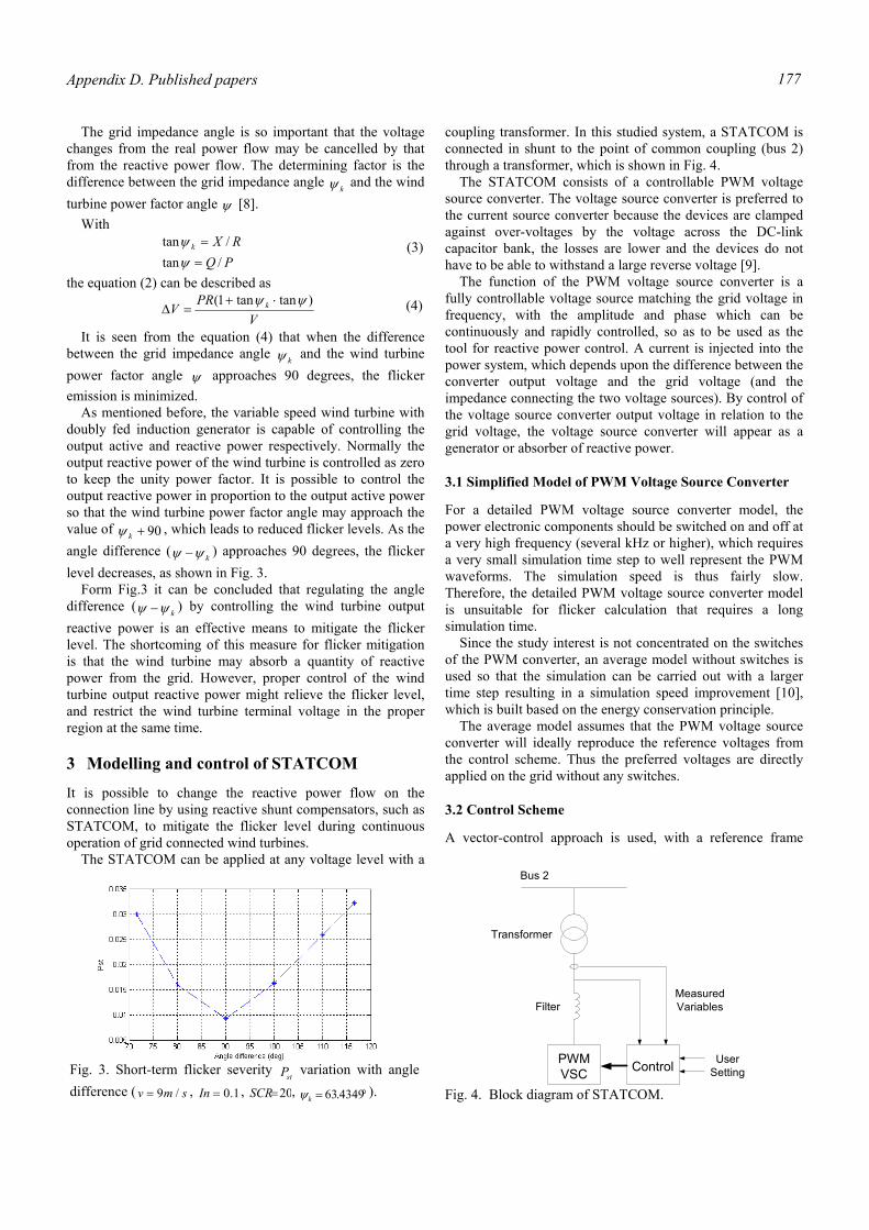
Appendix D. Published papers 177
The grid impedance angle is so important that the voltage changes from the real power flow may be cancelled by that from the reactive power flow. The determining factor is the difference between the grid impedance angle kψ and the wind turbine power factor angle ψ [8].
With
PQRXk
/tan/tan
==
ψψ (3)
the equation (2) can be described as
VPR
V k )tantan1( ψψ ⋅+=∆ (4)
It is seen from the equation (4) that when the difference between the grid impedance angle kψ and the wind turbine power factor angle ψ approaches 90 degrees, the flicker emission is minimized.
As mentioned before, the variable speed wind turbine with doubly fed induction generator is capable of controlling the output active and reactive power respectively. Normally the output reactive power of the wind turbine is controlled as zero to keep the unity power factor. It is possible to control the output reactive power in proportion to the output active power so that the wind turbine power factor angle may approach the value of 90+kψ , which leads to reduced flicker levels. As the angle difference ( kψψ − ) approaches 90 degrees, the flicker level decreases, as shown in Fig. 3.
Form Fig.3 it can be concluded that regulating the angle difference ( kψψ − ) by controlling the wind turbine output reactive power is an effective means to mitigate the flicker level. The shortcoming of this measure for flicker mitigation is that the wind turbine may absorb a quantity of reactive power from the grid. However, proper control of the wind turbine output reactive power might relieve the flicker level, and restrict the wind turbine terminal voltage in the proper region at the same time.
3 Modelling and control of STATCOM
It is possible to change the reactive power flow on the connection line by using reactive shunt compensators, such as STATCOM, to mitigate the flicker level during continuous operation of grid connected wind turbines.
The STATCOM can be applied at any voltage level with a
coupling transformer. In this studied system, a STATCOM is connected in shunt to the point of common coupling (bus 2) through a transformer, which is shown in Fig. 4.
The STATCOM consists of a controllable PWM voltage source converter. The voltage source converter is preferred to the current source converter because the devices are clamped against over-voltages by the voltage across the DC-link capacitor bank, the losses are lower and the devices do not have to be able to withstand a large reverse voltage [9].
The function of the PWM voltage source converter is a fully controllable voltage source matching the grid voltage in frequency, with the amplitude and phase which can be continuously and rapidly controlled, so as to be used as the tool for reactive power control. A current is injected into the power system, which depends upon the difference between the converter output voltage and the grid voltage (and the impedance connecting the two voltage sources). By control of the voltage source converter output voltage in relation to the grid voltage, the voltage source converter will appear as a generator or absorber of reactive power.
3.1 Simplified Model of PWM Voltage Source Converter
For a detailed PWM voltage source converter model, the power electronic components should be switched on and off at a very high frequency (several kHz or higher), which requires a very small simulation time step to well represent the PWM waveforms. The simulation speed is thus fairly slow. Therefore, the detailed PWM voltage source converter model is unsuitable for flicker calculation that requires a long simulation time.
Since the study interest is not concentrated on the switches of the PWM converter, an average model without switches is used so that the simulation can be carried out with a larger time step resulting in a simulation speed improvement [10], which is built based on the energy conservation principle.
The average model assumes that the PWM voltage source converter will ideally reproduce the reference voltages from the control scheme. Thus the preferred voltages are directly applied on the grid without any switches.
3.2 Control Scheme
A vector-control approach is used, with a reference frame
Fig. 3. Short-term flicker severity
stP variation with angledifference ( smv /9= , 1.0=In , 20=SCR , °= 4349.63kψ ).
PWMVSC Control
Bus 2
UserSetting
MeasuredVariables
Transformer
Filter
Fig. 4. Block diagram of STATCOM.
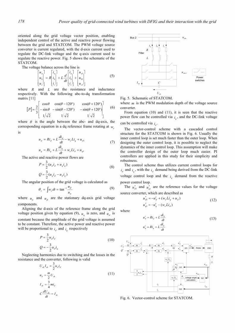
Power quality of grid-connected wind turbines with DFIG and their interaction with the grid 178
oriented along the grid voltage vector position, enabling independent control of the active and reactive power flowing between the grid and STATCOM. The PWM voltage source converter is current regulated, with the d-axis current used to regulate the DC-link voltage and the q-axis current used to regulate the reactive power. Fig. 5 shows the schematic of the STATCOM.
The voltage balance across the line is
+
+
=
1
1
1
c
b
a
c
b
a
c
b
a
c
b
a
uuu
iii
dtdL
iii
Ruuu
(5)
where R and L are the resistance and inductance respectively. With the following abc-to-dq transformation matrix [11]
[ ]
°+−°−−−°+°−
=
212121
)120sin()120sin(sin)120cos()120cos(cos
32 θθθ
θθθP (6)
where θ is the angle between the abc- and dq-axis, the corresponding equation in a dq reference frame rotating at ew is
1
1
qdeq
dqed
dd
uLiwdtdi
LRiu
uLiwdtdi
LRiu
+++=
+−+= (7)
The active and reactive power flows are
)(23
)(23
qddq
qqdd
iuiuQ
iuiuP
−=
+= (8)
The angular position of the grid voltage is calculated as
α
βθuu
dtwee1tan −== ∫ (9)
where αu and βu are the stationary dq-axis grid voltage
components. Aligning the d-axis of the reference frame along the grid voltage position given by equation (9),
qu is zero, and du is
constant because the amplitude of the grid voltage is assumed to be constant. Therefore, the active power and reactive power will be proportional to di and
qi respectively
qd
dd
iuQ
iuP
23
23
−=
= (10)
Neglecting harmonics due to switching and the losses in the resistance and the converter, following is valid
dcdc
ddc
dcd
dddcdc
Idt
dUC
miI
Umu
iuIU
=
=
=
=
432
23
(11)
where m is the PWM modulation depth of the voltage source converter.
From equation (10) and (11), it is seen that the reactive power flow can be controlled via
qi , and the DC-link voltage
can be controlled via di . The vector-control scheme with a cascaded control
structure for the STATCOM is shown in Fig. 6. Usually the inner control loop is set much faster than the outer loop. When designing the outer control loop, it is possible to neglect the dynamics of the inner control loop. This assumption will make the controller design of the outer loop much easier. PI controllers are applied in this study for their simplicity and robustness.
The control scheme thus utilizes current control loops for di and
qi , with the di demand being derived from the DC-link
voltage control loop and the qi demand from the reactive
power control loop. The *
1du and *1qu are the reference values for the voltage
source converter, which are described as
)(
)(*1
*1
deqq
dqedd
Liwuu
uLiwuu
−′−=
++′−= (12)
where
dtdi
LRiu
dtdi
LRiu
qqq
ddd
+=′
+=′ (13)
dcU
dcI
Bus 2
L
Rai bi ci
abcu
1abcu
Powerswitches
Filter
C
Fig. 5. Schematic of STATCOM.
PWM2/3
3/2voltage anglecalculation
3/2
3/2
PI
PI
qe Liw
de Liw
PI*dcU
dcU+
- *di +
-
du′
di
qi
*qi qu′
+ -
-
+
++
du
*1du
*1qu
- -
*1abcu
L
R
eθ
abcu
abci
αβu
PI*Q
qd iu23
−
Q+
-
VSC
Fig. 6. Vector-control scheme for STATCOM.
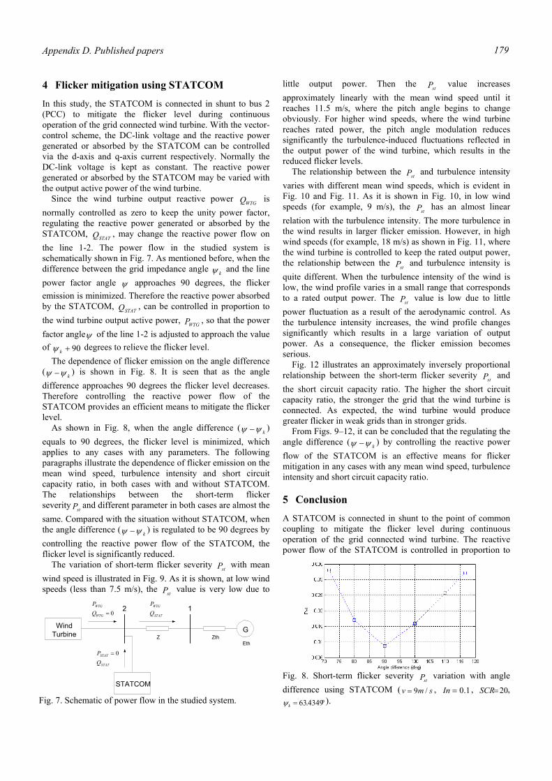
Appendix D. Published papers 179
4 Flicker mitigation using STATCOM
In this study, the STATCOM is connected in shunt to bus 2 (PCC) to mitigate the flicker level during continuous operation of the grid connected wind turbine. With the vector-control scheme, the DC-link voltage and the reactive power generated or absorbed by the STATCOM can be controlled via the d-axis and q-axis current respectively. Normally the DC-link voltage is kept as constant. The reactive power generated or absorbed by the STATCOM may be varied with the output active power of the wind turbine. Since the wind turbine output reactive power WTGQ is normally controlled as zero to keep the unity power factor, regulating the reactive power generated or absorbed by the STATCOM, STATQ , may change the reactive power flow on the line 1-2. The power flow in the studied system is schematically shown in Fig. 7. As mentioned before, when the difference between the grid impedance angle kψ and the line power factor angle ψ approaches 90 degrees, the flicker emission is minimized. Therefore the reactive power absorbed by the STATCOM, STATQ , can be controlled in proportion to the wind turbine output active power, WTGP , so that the power factor angleψ of the line 1-2 is adjusted to approach the value of 90+kψ degrees to relieve the flicker level.
The dependence of flicker emission on the angle difference ( kψψ − ) is shown in Fig. 8. It is seen that as the angle difference approaches 90 degrees the flicker level decreases. Therefore controlling the reactive power flow of the STATCOM provides an efficient means to mitigate the flicker level.
As shown in Fig. 8, when the angle difference ( kψψ − ) equals to 90 degrees, the flicker level is minimized, which applies to any cases with any parameters. The following paragraphs illustrate the dependence of flicker emission on the mean wind speed, turbulence intensity and short circuit capacity ratio, in both cases with and without STATCOM. The relationships between the short-term flicker severity stP and different parameter in both cases are almost the same. Compared with the situation without STATCOM, when the angle difference (
kψψ − ) is regulated to be 90 degrees by controlling the reactive power flow of the STATCOM, the flicker level is significantly reduced.
The variation of short-term flicker severity stP with mean wind speed is illustrated in Fig. 9. As it is shown, at low wind speeds (less than 7.5 m/s), the stP value is very low due to
little output power. Then the stP value increases approximately linearly with the mean wind speed until it reaches 11.5 m/s, where the pitch angle begins to change obviously. For higher wind speeds, where the wind turbine reaches rated power, the pitch angle modulation reduces significantly the turbulence-induced fluctuations reflected in the output power of the wind turbine, which results in the reduced flicker levels.
The relationship between the stP and turbulence intensity varies with different mean wind speeds, which is evident in Fig. 10 and Fig. 11. As it is shown in Fig. 10, in low wind speeds (for example, 9 m/s), the stP has an almost linear relation with the turbulence intensity. The more turbulence in the wind results in larger flicker emission. However, in high wind speeds (for example, 18 m/s) as shown in Fig. 11, where the wind turbine is controlled to keep the rated output power, the relationship between the stP and turbulence intensity is quite different. When the turbulence intensity of the wind is low, the wind profile varies in a small range that corresponds to a rated output power. The stP value is low due to little power fluctuation as a result of the aerodynamic control. As the turbulence intensity increases, the wind profile changes significantly which results in a large variation of output power. As a consequence, the flicker emission becomes serious.
Fig. 12 illustrates an approximately inversely proportional relationship between the short-term flicker severity stP and the short circuit capacity ratio. The higher the short circuit capacity ratio, the stronger the grid that the wind turbine is connected. As expected, the wind turbine would produce greater flicker in weak grids than in stronger grids.
From Figs. 9–12, it can be concluded that the regulating the angle difference ( kψψ − ) by controlling the reactive power flow of the STATCOM is an effective means for flicker mitigation in any cases with any mean wind speed, turbulence intensity and short circuit capacity ratio.
5 Conclusion
A STATCOM is connected in shunt to the point of common coupling to mitigate the flicker level during continuous operation of the grid connected wind turbine. The reactive power flow of the STATCOM is controlled in proportion to
GZ Zth
Eth
2 1
WindTurbine
STATCOM
STAT
STAT
QP 0=
0=WTG
WTG
QP
STAT
WTG
QP
Fig. 7. Schematic of power flow in the studied system.
Fig. 8. Short-term flicker severity
stP variation with angle difference using STATCOM ( smv /9= , 1.0=In , 20=SCR ,
°= 4349.63kψ ).
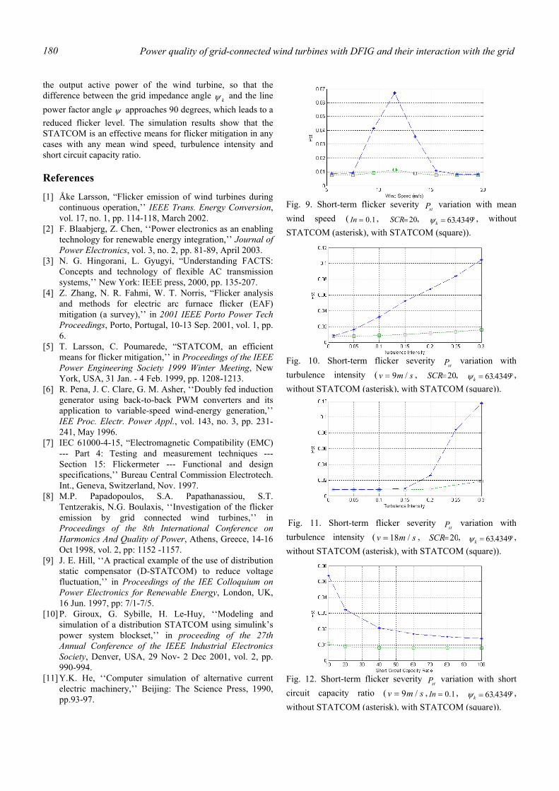
Power quality of grid-connected wind turbines with DFIG and their interaction with the grid 180
the output active power of the wind turbine, so that the difference between the grid impedance angle kψ and the line power factor angle ψ approaches 90 degrees, which leads to a reduced flicker level. The simulation results show that the STATCOM is an effective means for flicker mitigation in any cases with any mean wind speed, turbulence intensity and short circuit capacity ratio.
References
[1] Åke Larsson, “Flicker emission of wind turbines during continuous operation,’’ IEEE Trans. Energy Conversion, vol. 17, no. 1, pp. 114-118, March 2002.
[2] F. Blaabjerg, Z. Chen, ‘‘Power electronics as an enabling technology for renewable energy integration,’’ Journal of Power Electronics, vol. 3, no. 2, pp. 81-89, April 2003.
[3] N. G. Hingorani, L. Gyugyi, “Understanding FACTS: Concepts and technology of flexible AC transmission systems,’’ New York: IEEE press, 2000, pp. 135-207.
[4] Z. Zhang, N. R. Fahmi, W. T. Norris, “Flicker analysis and methods for electric arc furnace flicker (EAF) mitigation (a survey),’’ in 2001 IEEE Porto Power Tech Proceedings, Porto, Portugal, 10-13 Sep. 2001, vol. 1, pp. 6.
[5] T. Larsson, C. Poumarede, “STATCOM, an efficient means for flicker mitigation,’’ in Proceedings of the IEEE Power Engineering Society 1999 Winter Meeting, New York, USA, 31 Jan. - 4 Feb. 1999, pp. 1208-1213.
[6] R. Pena, J. C. Clare, G. M. Asher, ‘‘Doubly fed induction generator using back-to-back PWM converters and its application to variable-speed wind-energy generation,’’ IEE Proc. Electr. Power Appl., vol. 143, no. 3, pp. 231-241, May 1996.
[7] IEC 61000-4-15, “Electromagnetic Compatibility (EMC) --- Part 4: Testing and measurement techniques --- Section 15: Flickermeter --- Functional and design specifications,’’ Bureau Central Commission Electrotech. Int., Geneva, Switzerland, Nov. 1997.
[8] M.P. Papadopoulos, S.A. Papathanassiou, S.T. Tentzerakis, N.G. Boulaxis, ‘‘Investigation of the flicker emission by grid connected wind turbines,’’ in Proceedings of the 8th International Conference on Harmonics And Quality of Power, Athens, Greece, 14-16 Oct 1998, vol. 2, pp: 1152 -1157.
[9] J. E. Hill, ‘‘A practical example of the use of distribution static compensator (D-STATCOM) to reduce voltage fluctuation,’’ in Proceedings of the IEE Colloquium on Power Electronics for Renewable Energy, London, UK, 16 Jun. 1997, pp: 7/1-7/5.
[10] P. Giroux, G. Sybille, H. Le-Huy, ‘‘Modeling and simulation of a distribution STATCOM using simulink’s power system blockset,’’ in proceeding of the 27th Annual Conference of the IEEE Industrial Electronics Society, Denver, USA, 29 Nov- 2 Dec 2001, vol. 2, pp. 990-994.
[11] Y.K. He, ‘‘Computer simulation of alternative current electric machinery,’’ Beijing: The Science Press, 1990, pp.93-97.
Fig. 9. Short-term flicker severity
stP variation with mean wind speed ( 1.0=In , 20=SCR , °= 4349.63kψ , without STATCOM (asterisk), with STATCOM (square)).
Fig. 10. Short-term flicker severity
stP variation with turbulence intensity ( smv /9= , 20=SCR , °= 4349.63kψ , without STATCOM (asterisk), with STATCOM (square)).
Fig. 11. Short-term flicker severity stP variation with
turbulence intensity ( smv /18= , 20=SCR , °= 4349.63kψ , without STATCOM (asterisk), with STATCOM (square)).
Fig. 12. Short-term flicker severity
stP variation with short circuit capacity ratio ( smv /9= , 1.0=In , °= 4349.63kψ , without STATCOM (asterisk), with STATCOM (square)).
Appendix D. Published papers 181
Abstract—The fast development of wind power
generation brings new requirements for wind turbine integration to the network. After the clearance of an external short-circuit fault, the voltage at the wind turbine terminal should be re-established with minimized power losses. This paper concentrates on voltage recovery of variable speed wind turbines. The models of two different kinds of variable speed wind turbines, respectively with slip control and with doubly fed induction generator (DFIG), are developed in PSCAD/EMTDC. In both wind power generation systems, control strategies are proposed to re-establish the wind turbine terminal voltage after the clearance of an external short-circuit fault, which have been demonstrated by simulation results.
I. INTRODUCTION S a result of conventional energy sources consumption and increasing environmental concern,
efforts have been made to generate electricity from renewable sources, such as wind energy sources. Institutional support on wind energy sources, together with the wind energy potential and improvement of wind energy conversion technology, has led to a fast development of wind power generation in recent years.
The continuous increase of wind power penetration level is likely to influence the operation of the existing utilities’ networks, especially the power system stability. Specifications are now being revised to reflect new requirements for wind turbine integration to the network. According to the new requirements, after the clearance of a short-circuit fault in the external network, the voltage at the wind turbine terminal shall be re-established without wind turbine disconnection caused by inrush current and dipped voltage. The reason is, when the wind power penetration level is high, the protective disconnection of a large amount of wind power may cause an important loss of generation that may threaten the power system stability.
Regarding fixed speed wind turbines with conventional induction generators, the voltage recovery after the clearance of an external system fault may be assisted with dynamic reactive compensation, adjustment of relay settings of wind turbines, and control ability of wind turbines [1]. Adjusting the protective relay settings may be necessary for the wind turbines to stay grid-connected during a longer time at post-fault operational
situations. This makes it possible to rebuild the voltage with other means. However, the arrangement of adjusting the relay settings alone is not enough to solve the whole problem of re-establishing the voltage.
Compared with fixed speed wind turbines with conventional induction generators, variable speed wind turbines, respectively with slip control and with DFIG, have more control flexibilities. Therefore, it is possible to realize the voltage recovery of variable speed wind turbines through the control schemes implemented in the wind turbines. This paper concentrates on voltage recovery of variable speed wind turbines, respectively with slip control and with DFIG. The models of such two kinds of variable speed wind turbines developed in PSCAD/EMTDC are presented, and the control and protection schemes of the wind turbines are described. In both wind power generation systems, control strategies are proposed to re-establish the wind turbine terminal voltage after the clearance of an external short-circuit fault, which have been demonstrated by simulation results.
II. WIND TURBINE MODEL Two kinds of variable speed wind turbines are
considered in this paper. The variable speed wind turbine with slip control is a very low-cost and simple variable speed system. However, this topology can only provide a limited speed-range operation. Variable speed wind turbines with DFIG are the most popular variable speed wind turbines worldwide, which is capable of providing wide speed-range operation.
The complete wind turbine model includes the wind speed model, the aerodynamic model of the wind turbine, the mechanical model of the transmission system, models of the electrical components, and the control and supervisory system.
The simulation models of these two kinds of variable speed wind turbines are developed in the dedicated power system analysis tool, PSCAD/EMTDC. The grid and the electrical components of the wind turbines are built with standard electrical component models from PSCAD/EMTDC library. The models of the wind speed and the aerodynamic, mechanical and control components of the wind turbine are built with custom components developed in PSCAD/EMTDC. The block
Comparative Study of Voltage Recovery Behaviors of Grid-Connected Wind Turbines
Tao Sun, Z. Chen, Frede Blaabjerg
Aalborg University, DK-9220 Aalborg, Denmark
A
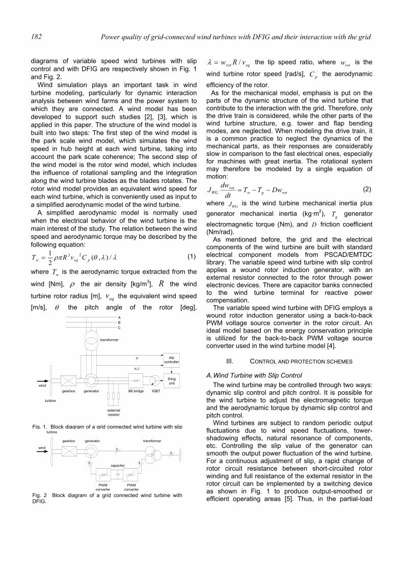
Power quality of grid-connected wind turbines with DFIG and their interaction with the grid 182
diagrams of variable speed wind turbines with slip control and with DFIG are respectively shown in Fig. 1 and Fig. 2.
Wind simulation plays an important task in wind turbine modeling, particularly for dynamic interaction analysis between wind farms and the power system to which they are connected. A wind model has been developed to support such studies [2], [3], which is applied in this paper. The structure of the wind model is built into two steps: The first step of the wind model is the park scale wind model, which simulates the wind speed in hub height at each wind turbine, taking into account the park scale coherence; The second step of the wind model is the rotor wind model, which includes the influence of rotational sampling and the integration along the wind turbine blades as the blades rotates. The rotor wind model provides an equivalent wind speed for each wind turbine, which is conveniently used as input to a simplified aerodynamic model of the wind turbine.
A simplified aerodynamic model is normally used when the electrical behavior of the wind turbine is the main interest of the study. The relation between the wind speed and aerodynamic torque may be described by the following equation:
λλθρπ /),(21 23
peqw CvRT = (1)
where wT is the aerodynamic torque extracted from the
wind [Nm], ρ the air density [kg/m3], R the wind
turbine rotor radius [m], eqv the equivalent wind speed
[m/s], θ the pitch angle of the rotor [deg],
eqrot vRw /=λ the tip speed ratio, where rotw is the
wind turbine rotor speed [rad/s], pC the aerodynamic efficiency of the rotor.
As for the mechanical model, emphasis is put on the parts of the dynamic structure of the wind turbine that contribute to the interaction with the grid. Therefore, only the drive train is considered, while the other parts of the wind turbine structure, e.g. tower and flap bending modes, are neglected. When modeling the drive train, it is a common practice to neglect the dynamics of the mechanical parts, as their responses are considerably slow in comparison to the fast electrical ones, especially for machines with great inertia. The rotational system may therefore be modeled by a single equation of motion:
rotgwrot
WG DwTTdt
dwJ −−= (2)
where WGJ is the wind turbine mechanical inertia plus generator mechanical inertia (kg·m2), gT generator electromagnetic torque (Nm), and D friction coefficient (Nm/rad). As mentioned before, the grid and the electrical components of the wind turbine are built with standard electrical component models from PSCAD/EMTDC library. The variable speed wind turbine with slip control applies a wound rotor induction generator, with an external resistor connected to the rotor through power electronic devices. There are capacitor banks connected to the wind turbine terminal for reactive power compensation. The variable speed wind turbine with DFIG employs a wound rotor induction generator using a back-to-back PWM voltage source converter in the rotor circuit. An ideal model based on the energy conservation principle is utilized for the back-to-back PWM voltage source converter used in the wind turbine model [4].
III. CONTROL AND PROTECTION SCHEMES
A. Wind Turbine with Slip Control The wind turbine may be controlled through two ways:
dynamic slip control and pitch control. It is possible for the wind turbine to adjust the electromagnetic torque and the aerodynamic torque by dynamic slip control and pitch control.
Wind turbines are subject to random periodic output fluctuations due to wind speed fluctuations, tower-shadowing effects, natural resonance of components, etc. Controlling the slip value of the generator can smooth the output power fluctuation of the wind turbine. For a continuous adjustment of slip, a rapid change of rotor circuit resistance between short-circuited rotor winding and full resistance of the external resistor in the rotor circuit can be implemented by a switching device as shown in Fig. 1 to produce output-smoothed or efficient operating areas [5]. Thus, in the partial-load
gearbox generator
firingunit
externalresistor
B6 bridge IGBT
A
CB
slipcontroller
n
iu,
wind
turbine
transformer
Fig. 1. Block diagram of a grid connected wind turbine with slip
wind
turbine
generator transformer
PWMconverter
PWMconverter
capacitor
gearbox
3
3 3
3
Fig. 2 Block diagram of a grid connected wind turbine withDFIG.
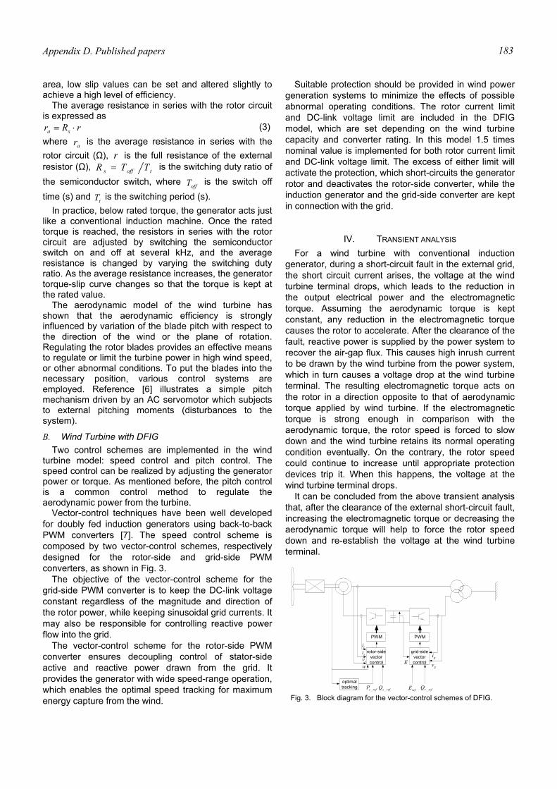
Appendix D. Published papers 183
area, low slip values can be set and altered slightly to achieve a high level of efficiency.
The average resistance in series with the rotor circuit is expressed as
rRr sa ⋅= (3) where ar is the average resistance in series with the rotor circuit (Ω), r is the full resistance of the external resistor (Ω), toffs TTR = is the switching duty ratio of the semiconductor switch, where offT is the switch off time (s) and tT is the switching period (s).
In practice, below rated torque, the generator acts just like a conventional induction machine. Once the rated torque is reached, the resistors in series with the rotor circuit are adjusted by switching the semiconductor switch on and off at several kHz, and the average resistance is changed by varying the switching duty ratio. As the average resistance increases, the generator torque-slip curve changes so that the torque is kept at the rated value.
The aerodynamic model of the wind turbine has shown that the aerodynamic efficiency is strongly influenced by variation of the blade pitch with respect to the direction of the wind or the plane of rotation. Regulating the rotor blades provides an effective means to regulate or limit the turbine power in high wind speed, or other abnormal conditions. To put the blades into the necessary position, various control systems are employed. Reference [6] illustrates a simple pitch mechanism driven by an AC servomotor which subjects to external pitching moments (disturbances to the system).
B. Wind Turbine with DFIG Two control schemes are implemented in the wind
turbine model: speed control and pitch control. The speed control can be realized by adjusting the generator power or torque. As mentioned before, the pitch control is a common control method to regulate the aerodynamic power from the turbine.
Vector-control techniques have been well developed for doubly fed induction generators using back-to-back PWM converters [7]. The speed control scheme is composed by two vector-control schemes, respectively designed for the rotor-side and grid-side PWM converters, as shown in Fig. 3.
The objective of the vector-control scheme for the grid-side PWM converter is to keep the DC-link voltage constant regardless of the magnitude and direction of the rotor power, while keeping sinusoidal grid currents. It may also be responsible for controlling reactive power flow into the grid.
The vector-control scheme for the rotor-side PWM converter ensures decoupling control of stator-side active and reactive power drawn from the grid. It provides the generator with wide speed-range operation, which enables the optimal speed tracking for maximum energy capture from the wind.
Suitable protection should be provided in wind power generation systems to minimize the effects of possible abnormal operating conditions. The rotor current limit and DC-link voltage limit are included in the DFIG model, which are set depending on the wind turbine capacity and converter rating. In this model 1.5 times nominal value is implemented for both rotor current limit and DC-link voltage limit. The excess of either limit will activate the protection, which short-circuits the generator rotor and deactivates the rotor-side converter, while the induction generator and the grid-side converter are kept in connection with the grid.
IV. TRANSIENT ANALYSIS For a wind turbine with conventional induction
generator, during a short-circuit fault in the external grid, the short circuit current arises, the voltage at the wind turbine terminal drops, which leads to the reduction in the output electrical power and the electromagnetic torque. Assuming the aerodynamic torque is kept constant, any reduction in the electromagnetic torque causes the rotor to accelerate. After the clearance of the fault, reactive power is supplied by the power system to recover the air-gap flux. This causes high inrush current to be drawn by the wind turbine from the power system, which in turn causes a voltage drop at the wind turbine terminal. The resulting electromagnetic torque acts on the rotor in a direction opposite to that of aerodynamic torque applied by wind turbine. If the electromagnetic torque is strong enough in comparison with the aerodynamic torque, the rotor speed is forced to slow down and the wind turbine retains its normal operating condition eventually. On the contrary, the rotor speed could continue to increase until appropriate protection devices trip it. When this happens, the voltage at the wind turbine terminal drops.
It can be concluded from the above transient analysis that, after the clearance of the external short-circuit fault, increasing the electromagnetic torque or decreasing the aerodynamic torque will help to force the rotor speed down and re-establish the voltage at the wind turbine terminal.
PWM PWM
rotor-sidevectorcontrol
grid-sidevectorcontrol
gi
gvE
risisv
w
optimaltracking refsP _ refsQ _ refE refrQ _
Fig. 3. Block diagram for the vector-control schemes of DFIG.

Power quality of grid-connected wind turbines with DFIG and their interaction with the grid 184
V. CONTROL STRATEGIES AND SIMULATION RESULTS The study has been conducted on the system shown
in Fig. 4, which represents a typical situation, where a load at bus 2 is supplied by a wind farm represented by a single machine and by the external power system represented by a constant voltage source connected in series with its Thevenin’s equivalent impedance. The external power system connects to bus 2 through two parallel lines, and bus 2 is the point of common coupling.
The fault event is a three-phase to ground short-circuit fault on one of the two parallel lines. It begins at 2 s and after 150 ms the line is tripped.
A. Wind Turbine with Slip Control After the clearance of the short-circuit fault, regulating
the generator slip and pitch angle can increase the electromagnetic torque and decrease the aerodynamic torque of wind turbine, which helps to re-establish the voltage at the wind turbine terminal.
Fig. 5 shows the effect of re-establishing the wind turbine voltage by regulating the generator slip and the blade pitch angle after the clearance of a short-circuit fault. During the short-circuit fault, i.e. 2 – 2.15 s, the short circuit current arises, the voltage at the wind turbine terminal drops. Due to the voltage dip, the output electrical power and the electromagnetic torque are significantly reduced. Since the aerodynamic torque is almost kept invariable, any reduction in the electro-magnetic torque causes the rotor to accelerate. After the clearance of the fault, i.e. 2.15 s, reactive power is supplied by the power system to recover the air-gap flux. This causes high inrush current to be drawn by the wind turbine from the power system, which in turn causes a voltage drop at the wind turbine terminal.
Since 2.25 s, the pitch angle and switching duty ratio are regulated to reduce the aerodynamic torque, and at the same time, to strengthen the electromagnetic torque. The pitch rate is limited by sec/5°± . After the voltage has been recovered, i.e. approximately 3.75 s, the pitch angle and switch duty ratio are adjusted back to the initial values. It can be seen that dynamic slip control and pitch control provide an effective and quick means to rebuild the wind turbine voltage after the fault clearance.
B. Wind Turbine with DFIG A new control strategy is proposed to contribute to re-
establish the voltage at wind turbine terminal without any wind turbine disconnection after a short-circuit fault. This control strategy takes advantage of the benefits of pitch controlled variable speed wind turbine.
After an occurrence of a short-circuit fault in the external networks, the following control steps are performed: 1. The excess of either the rotor current limit or the DC-
link voltage limit will activate the protection to short-circuit the generator rotor and deactivate the rotor-side converter, while the induction generator and the grid-side converter are kept in connection with the grid.
Fig. 5. Voltage, torques, generator rotor speed, current, output power, pitch angle and switching duty ratio under combined control of generator slip and pitch angle.
Bus2
P, Q
G
Bus1Zth
Z
Z/2 Z/2
Eth
variable speedwind turbine
Fig. 4 Studied system.

Appendix D. Published papers 185
2. Regulating the pitch angle reduces the aerodynamic power. Thus the generator rotor speed is slowed down which leads to the voltage recovery at the wind turbine terminal.
3. After the clearance of the short-circuit fault and the voltage recovery of the wind turbine, the rotor-side converter is put back into work and the DIFG restores it normal operation.
In Fig.6 the simulation results for the control strategy implemented in the studied system are shown.
Immediately after the fault occurs, the short-circuit current increases and the stator voltage and flux drop towards zero. The rotor current then increases to attempt to maintain the flux linkage [8]. The increase of the rotor current in turn causes the rise of the rotor voltage and the DC-link voltage. Meanwhile, the drop of the stator voltage and flux results in the significant reduction in the electromagnetic torque and power. Assuming the mechanical torque is kept constant, any reduction in the electromagnetic torque causes the rotor to accelerate.
Once the DC-link voltage exceeds the limit, at approximately 2.008 s, the generator rotor is short-circuited and the rotor-side converter is deactivated after a 40 ms time delay, while the grid-side converter is kept in connection with the grid, which is responsible for keeping the DC-link voltage constant and ensuring zero reactive power flow between the converter and the grid. From this moment on, the generator behaves as a conventional induction generator. It has been noticed that the DC-link voltage begins to decrease after the protection trip and retains its nominal value quickly.
Increasing the pitch angle may reduce the aerodynamic torque, which helps to slow the rotor speed down and re-establish the voltage at the wind turbine terminal. It is assumed that a control signal to order the reduction of aerodynamic torque is given when the generator rotor is short-circuited. The pitch rate is limited by sec/5°± . As it is shown in Fig. 6, since approximately 2.048 s the pitch angle is increased to reduce the aerodynamic torque, which leads to the reduction of the rotor speed and the recovery of the wind turbine terminal voltage. It can be seen, before the voltage is rebuilt, a large amount of reactive power is drawn from the grid that results in high inrush current. After the generator rotor speed is forced down and the voltage has been recovered, i.e. approximately 6.3 s, the pitch angle is adjusted back to the normal value to produce more power. As the generator operates as a conventional induction generator, the generator speed is near the synchronous speed and a quantity of reactive power is drawn from the external grid.
After the clearance of the external short-circuit, the rotor-side converter is put back into work about 6 s later than the voltage recovery of the wind turbine. The controllers of the PWM back-to-back voltage source converter then try to control the DFIG as normal. The
rotor-side controller tries to control the stator-side active power according to the generator rotor speed, while reducing the stator-side reactive power to zero. The grid-side controller maintains the DC-link voltage as constant and, at the same time, ensures zero reactive power exchange between the grid-side converter and the grid.
Fig. 6. Voltage, stator current, DC-link voltage, torques, generator rotor speed, active power, reactive power and pitch angle in the simulated case.
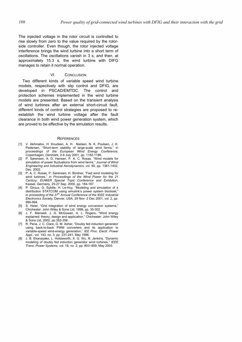
Power quality of grid-connected wind turbines with DFIG and their interaction with the grid 186
The injected voltage in the rotor circuit is controlled to rise slowly from zero to the value required by the rotor-side controller. Even though, the rotor injected voltage interference brings the wind turbine into a short term of oscillations. The oscillations vanish in 3 s, and then, at approximately 15.3 s, the wind turbine with DIFG manages to retain it normal operation.
VI. CONCLUSION Two different kinds of variable speed wind turbine
models, respectively with slip control and DFIG, are developed in PSCAD/EMTDC. The control and protection schemes implemented in the wind turbine models are presented. Based on the transient analysis of wind turbines after an external short-circuit fault, different kinds of control strategies are proposed to re-establish the wind turbine voltage after the fault clearance in both wind power generation system, which are proved to be effective by the simulation results.
REFERENCES [1] V. Akhmatov, H. Knudsen, A. H. Nielsen, N. K. Poulsen, J. K.
Pedersen, “Short-term stability of large-scale wind farms,” in proceedings of the European Wind Energy Conference, Copenhagen, Denmark, 2-6 July 2001, pp. 1182-1186.
[2] P. Sørensen, A. D. Hansen, P. A. C. Rosas, “Wind models for simulation of power fluctuations from wind farms,” Journal of Wind Engineering and Industrial Aerodynamics, vol. 90, pp. 1381-1402, Dec. 2002.
[3] P. A. C. Rosas, P. Sørensen, H. Bindner, “Fast wind modeling for wind turbines,” in Proceedings of the Wind Power for the 21 Century: EUWER Special Topic Conference and Exhibition, Kassel, Germany, 25-27 Sep. 2000, pp. 184-187.
[4] P. Giroux, G. Sybille, H. Le-Huy, “Modeling and simulation of a distribution STATCOM using simulink’s power system blockset,” in proceeding of the 27th Annual Conference of the IEEE Industrial Electronics Society, Denver, USA, 29 Nov- 2 Dec 2001, vol. 2, pp. 990-994.
[5] S. Heier, “Grid integration of wind energy conversion systems,” Chichester: John Wiley & Sons Ltd, 1998, pp. 35-302.
[6] J. F. Manwell, J. G. McGowan, A. L. Rogers, “Wind energy explained: theory, design and application,” Chichester: John Wiley & Sons Ltd, 2002, pp.352-358.
[7] R. Pena, J. C. Clare, G. M. Asher, “Doubly fed induction generator using back-to-back PWM converters and its application to variable-speed wind-energy generation,” IEE Proc. Electr. Power Appl., vol. 143, no. 3, pp. 231-241, May 1996.
[8] J. B. Ekanayake, L. Holdsworth, X. G. Wu, N. Jenkins, “Dynamic modeling of doubly fed induction generator wind turbines,” IEEE Trans. Power Systems, vol. 18, no. 2, pp. 803–809, May 2003.
Appendix D. Published papers 187
Abstract—The fast development of wind power generation
brings new requirements for wind turbine integration to the network. After the clearance of an external short-circuit fault, the voltage at the wind turbine terminal should be re-established with minimized power losses. This paper concentrates on voltage recovery of variable speed wind turbines with doubly fed induction generators (DFIG). A simulation model of a MW-level variable speed wind turbine with a DFIG developed in PSCAD/EMTDC is presented, and the control and protection schemes are described. A new control strategy is proposed to re-establish the wind turbine terminal voltage after the clearance of an external short-circuit fault, and then restore the normal operation of the variable speed wind turbine with DFIG, which has been demonstrated by simulation results.
I. INTRODUCTION As a result of conventional energy sources consumption
and increasing environmental concern, efforts have been made to generate electricity from renewable energy sources, such as wind energy. Institutional and governmental support on wind energy sources, together with the wind energy potential and improvement of wind energy conversion technology, has led to a fast development of wind power generation in recent years.
The continuous increase of the wind power penetration level is likely to influence the operation of the existing utilities networks, especially the power system stability. Specifications are now being revised to reflect new requirements for wind turbine integration to the network. According to the specification in Denmark [1], at a short-circuit fault in the external grid, the voltages at the wind turbine terminals should be re-established after the fault clearance without any power loss caused by disconnection of wind turbines. The similar requirements can be found in the specifications in Germany, the Netherlands, England and Wales [2]. The reason is, when the wind power penetration level is high, the protective disconnection of a large amount of wind power will be an unacceptable consequence that may threaten the power system stability. Regarding fixed speed wind turbines with conventional induction generators, the voltage recovery after the clearance of an external system fault may be assisted with dynamic reactive compensation, adjustment of relay settings of wind turbines, and control ability of wind turbines [3], [4]. For variable speed wind turbines with slip control, dynamic slip control and pitch control may contribute to rebuild the voltage
at the wind turbine terminal and maintain the power system stability after the clearance of an external short-circuit fault [5]. Variable speed wind turbines with DFIG, presently the most popular installed variable speed wind turbines worldwide, have shown better behaviors concerning system stability during short-circuit faults in comparison with fixed speed wind turbines [6], [7]. However, there are few literatures related to voltage recovery of variable speed wind turbines with DFIG after the clearance of an external short-circuit fault.
This paper concentrates on voltage recovery of variable speed wind turbines with DFIG after the clearance of an external short-circuit fault. A simulation model of a MW-level wind turbine with a DFIG developed in PSCAD/EMTDC is presented, and the control and protection schemes of the wind turbine are described. Based on the wind turbine model, the stability of wind turbine after an external short-circuit fault has been investigated. A new control strategy is proposed to re-establish the wind turbine terminal voltage after the clearance of an external short-circuit fault, and then restore the normal operation of the variable speed wind turbine with DFIG, which has been demonstrated by simulation results. An emergency pitch regulation scheme is also developed, which is applied for power reduction in the situation of faults.
II. WIND TURBINE MODEL The wind turbine considered here applies a DFIG, using a
back-to-back PWM voltage source converter in the rotor circuit. Variable speed operation of the wind turbine can be realized by appropriate adjustment of the rotor speed and pitch angle.
A complete wind turbine model includes the wind speed model, the aerodynamic model of the wind turbine rotor, the mechanical model of the transmission system and models of the electrical components, namely the induction generator, PWM voltage source converters, transformer, and the control and supervisory system. Fig. 1 illustrates the main components of a grid-connected wind turbine.
The simulation model of the wind turbine is developed in the dedicated power system analysis tool, PSCAD/EMTDC. The grid model and the electrical components of the wind turbine are built with standard electrical component models from PSCAD/EMTDC library. The models of the wind speed and the aerodynamic, mechanical and control components of the wind turbine are built with custom components developed in PSCAD/EMTDC.
Voltage Recovery of Grid-Connected Wind Turbines with DFIG After a Short-Circuit Fault
T. Sun
North China Electric Power University, China
Electric Power Research Institute, China Aalborg University, Aalborg, Denmark
Email: tsu@iet auc dk
Z. Chen Aalborg University, Aalborg, Denmark
De Montfort University, UK Email: [email protected]
F. Blaabjerg
Aalborg University Aalborg, Denmark
Email: [email protected]
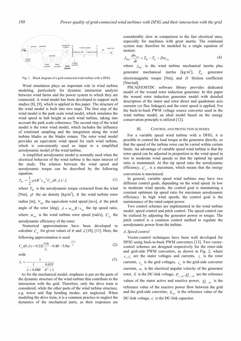
Power quality of grid-connected wind turbines with DFIG and their interaction with the grid 188
Wind simulation plays an important role in wind turbine modeling, particularly for dynamic interaction analysis between wind farms and the power system to which they are connected. A wind model has been developed to support such studies [8], [9], which is applied in this paper. The structure of the wind model is built into two steps: The first step of the wind model is the park scale wind model, which simulates the wind speed in hub height at each wind turbine, taking into account the park scale coherence; The second step of the wind model is the rotor wind model, which includes the influence of rotational sampling and the integration along the wind turbine blades as the blades rotates. The rotor wind model provides an equivalent wind speed for each wind turbine, which is conveniently used as input to a simplified aerodynamic model of the wind turbine.
A simplified aerodynamic model is normally used when the electrical behavior of the wind turbine is the main interest of the study. The relation between the wind speed and aerodynamic torque can be described by the following equation:
λλθρπ /),(21 23
peqW CvRT = (1)
where WT is the aerodynamic torque extracted from the wind [Nm], ρ the air density [kg/m3], R the wind turbine rotor
radius [m], eqv the equivalent wind speed [m/s], θ the pitch
angle of the rotor [deg], eqrot vRw /=λ the tip speed ratio,
where rotw is the wind turbine rotor speed [rad/s], pC the
aerodynamic efficiency of the rotor. Numerical approximations have been developed to
calculate pC for given values of θ and λ [10], [11]. Here, the
following approximation is used
ieCi
pλθ
λλθ
5.12
)0.54.0116(22.0),(−
−−= (2)
with
1035.0
08.01
1
3 +−
+
=
θθλ
λi (3)
As for the mechanical model, emphasis is put on the parts of the dynamic structure of the wind turbine that contribute to the interaction with the grid. Therefore, only the drive train is considered, while the other parts of the wind turbine structure, e.g. tower and flap bending modes, are neglected. When modeling the drive train, it is a common practice to neglect the dynamics of the mechanical parts, as their responses are
considerably slow in comparison to the fast electrical ones, especially for machines with great inertia. The rotational system may therefore be modeled by a single equation of motion:
rotGWrot
WG DwTTdt
dwJ −−= (4)
where WGJ is the wind turbine mechanical inertia plus generator mechanical inertia [kg·m2], GT generator electromagnetic torque [Nm], and D friction coefficient [Nm/rad].
PSCAD/EMTDC software library provides dedicated model of the wound rotor induction generator. In this paper the wound rotor induction generator model with detailed description of the stator and rotor direct and quadrature axis currents (or flux linkages) and the rotor speed is applied. For the back-to-back PWM voltage source converter used in the wind turbine model, an ideal model based on the energy conservation principle is utilized [12].
III. CONTROL AND PROTECTION SCHEMES For a variable speed wind turbine with a DFIG, it is
possible to control the load torque at the generator directly, so that the speed of the turbine rotor can be varied within certain limits. An advantage of variable speed wind turbine is that the rotor speed can be adjusted in proportion to the wind speed in low to moderate wind speeds so that the optimal tip speed ratio is maintained. At this tip speed ratio the aerodynamic efficiency,
pC , is a maximum, which means that the energy
conversion is maximized. In general, variable speed wind turbines may have two
different control goals, depending on the wind speed. In low to moderate wind speeds, the control goal is maintaining a constant optimum tip speed ratio for maximum aerodynamic efficiency. In high wind speeds, the control goal is the maintenance of the rated output power.
Two control schemes are implemented in the wind turbine model: speed control and pitch control. The speed control can be realized by adjusting the generator power or torque. The pitch control is a common control method to regulate the aerodynamic power from the turbine.
A. Speed control Vector-control techniques have been well developed for
DFIG using back-to-back PWM converters [13]. Two vector-control schemes are designed respectively for the rotor-side and grid-side PWM converters, as shown in Fig. 2, where
ss iv , are the stator voltages and currents, ri is the rotor currents, gv is the grid voltages, gi is the grid-side converter
currents, rw is the electrical angular velocity of the generator rotor, E is the DC-link voltage, refsrefs QP __ , are the reference
values of the stator active and reactive power, refrQ _
is the
reference value of the reactive power flow between the grid and the grid-side converter,
refE is the reference value of the
DC-link voltage, C is the DC-link capacitor.
3-bladeturbine
gearboxtransformer
2.5MVA 2wind
generator
capacitor
PWMconverter
PWMconverter wind
turbine
P=4MWQ=2MVA
G
Eth=11kV1
Zth0.1691+j0.3382
0.0845+j0.1691 0.0845+j0.1691
Fig. 1. Block diagram of a grid-connected wind turbine with a DFIG.
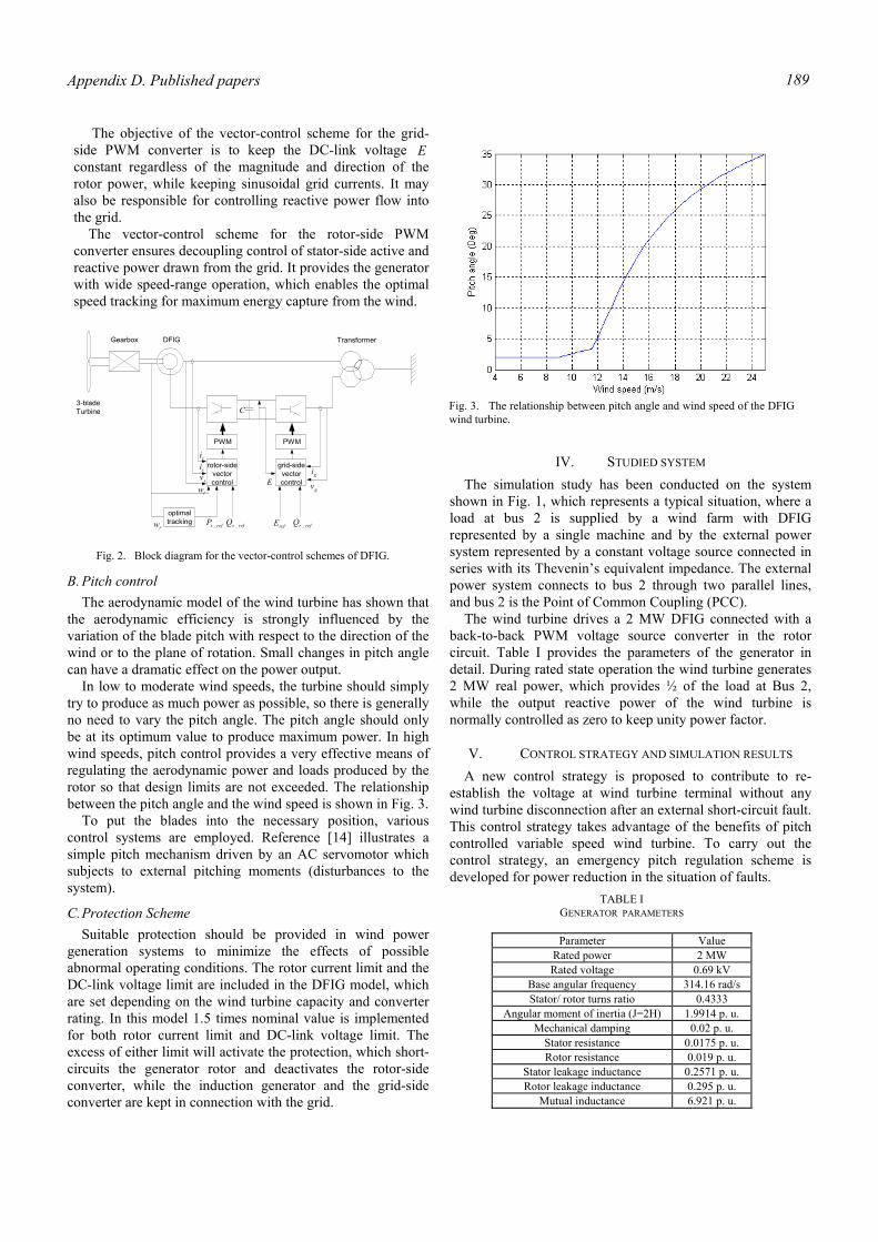
Appendix D. Published papers 189
The objective of the vector-control scheme for the grid-side PWM converter is to keep the DC-link voltage E constant regardless of the magnitude and direction of the rotor power, while keeping sinusoidal grid currents. It may also be responsible for controlling reactive power flow into the grid.
The vector-control scheme for the rotor-side PWM converter ensures decoupling control of stator-side active and reactive power drawn from the grid. It provides the generator with wide speed-range operation, which enables the optimal speed tracking for maximum energy capture from the wind.
B. Pitch control The aerodynamic model of the wind turbine has shown that
the aerodynamic efficiency is strongly influenced by the variation of the blade pitch with respect to the direction of the wind or to the plane of rotation. Small changes in pitch angle can have a dramatic effect on the power output.
In low to moderate wind speeds, the turbine should simply try to produce as much power as possible, so there is generally no need to vary the pitch angle. The pitch angle should only be at its optimum value to produce maximum power. In high wind speeds, pitch control provides a very effective means of regulating the aerodynamic power and loads produced by the rotor so that design limits are not exceeded. The relationship between the pitch angle and the wind speed is shown in Fig. 3.
To put the blades into the necessary position, various control systems are employed. Reference [14] illustrates a simple pitch mechanism driven by an AC servomotor which subjects to external pitching moments (disturbances to the system).
C. Protection Scheme Suitable protection should be provided in wind power
generation systems to minimize the effects of possible abnormal operating conditions. The rotor current limit and the DC-link voltage limit are included in the DFIG model, which are set depending on the wind turbine capacity and converter rating. In this model 1.5 times nominal value is implemented for both rotor current limit and DC-link voltage limit. The excess of either limit will activate the protection, which short-circuits the generator rotor and deactivates the rotor-side converter, while the induction generator and the grid-side converter are kept in connection with the grid.
IV. STUDIED SYSTEM The simulation study has been conducted on the system
shown in Fig. 1, which represents a typical situation, where a load at bus 2 is supplied by a wind farm with DFIG represented by a single machine and by the external power system represented by a constant voltage source connected in series with its Thevenin’s equivalent impedance. The external power system connects to bus 2 through two parallel lines, and bus 2 is the Point of Common Coupling (PCC).
The wind turbine drives a 2 MW DFIG connected with a back-to-back PWM voltage source converter in the rotor circuit. Table I provides the parameters of the generator in detail. During rated state operation the wind turbine generates 2 MW real power, which provides ½ of the load at Bus 2, while the output reactive power of the wind turbine is normally controlled as zero to keep unity power factor.
V. CONTROL STRATEGY AND SIMULATION RESULTS A new control strategy is proposed to contribute to re-
establish the voltage at wind turbine terminal without any wind turbine disconnection after an external short-circuit fault. This control strategy takes advantage of the benefits of pitch controlled variable speed wind turbine. To carry out the control strategy, an emergency pitch regulation scheme is developed for power reduction in the situation of faults.
Fig. 3. The relationship between pitch angle and wind speed of the DFIG wind turbine.
PWM PWM
rotor-sidevectorcontrol
grid-sidevectorcontrol
gi
gvE
risisv
rw
optimaltracking refsP _ refsQ _ refE refrQ _
3-bladeTurbine
Gearbox DFIG Transformer
C
rw
Fig. 2. Block diagram for the vector-control schemes of DFIG.
TABLE I GENERATOR PARAMETERS
Parameter Value
Rated power 2 MW Rated voltage 0.69 kV
Base angular frequency 314.16 rad/s Stator/ rotor turns ratio 0.4333
Angular moment of inertia (J=2H) 1.9914 p. u. Mechanical damping 0.02 p. u.
Stator resistance 0.0175 p. u. Rotor resistance 0.019 p. u.
Stator leakage inductance 0.2571 p. u. Rotor leakage inductance 0.295 p. u.
Mutual inductance 6.921 p. u.
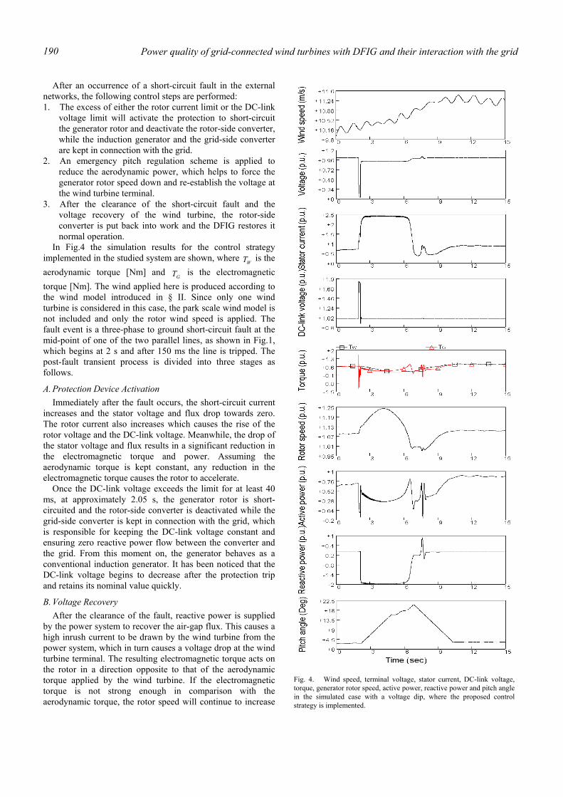
Power quality of grid-connected wind turbines with DFIG and their interaction with the grid 190
After an occurrence of a short-circuit fault in the external networks, the following control steps are performed: 1. The excess of either the rotor current limit or the DC-link
voltage limit will activate the protection to short-circuit the generator rotor and deactivate the rotor-side converter, while the induction generator and the grid-side converter are kept in connection with the grid.
2. An emergency pitch regulation scheme is applied to reduce the aerodynamic power, which helps to force the generator rotor speed down and re-establish the voltage at the wind turbine terminal.
3. After the clearance of the short-circuit fault and the voltage recovery of the wind turbine, the rotor-side converter is put back into work and the DFIG restores it normal operation.
In Fig.4 the simulation results for the control strategy implemented in the studied system are shown, where
WT is the aerodynamic torque [Nm] and
GT is the electromagnetic torque [Nm]. The wind applied here is produced according to the wind model introduced in § II. Since only one wind turbine is considered in this case, the park scale wind model is not included and only the rotor wind speed is applied. The fault event is a three-phase to ground short-circuit fault at the mid-point of one of the two parallel lines, as shown in Fig.1, which begins at 2 s and after 150 ms the line is tripped. The post-fault transient process is divided into three stages as follows.
A. Protection Device Activation Immediately after the fault occurs, the short-circuit current
increases and the stator voltage and flux drop towards zero. The rotor current also increases which causes the rise of the rotor voltage and the DC-link voltage. Meanwhile, the drop of the stator voltage and flux results in a significant reduction in the electromagnetic torque and power. Assuming the aerodynamic torque is kept constant, any reduction in the electromagnetic torque causes the rotor to accelerate.
Once the DC-link voltage exceeds the limit for at least 40 ms, at approximately 2.05 s, the generator rotor is short-circuited and the rotor-side converter is deactivated while the grid-side converter is kept in connection with the grid, which is responsible for keeping the DC-link voltage constant and ensuring zero reactive power flow between the converter and the grid. From this moment on, the generator behaves as a conventional induction generator. It has been noticed that the DC-link voltage begins to decrease after the protection trip and retains its nominal value quickly.
B. Voltage Recovery After the clearance of the fault, reactive power is supplied
by the power system to recover the air-gap flux. This causes a high inrush current to be drawn by the wind turbine from the power system, which in turn causes a voltage drop at the wind turbine terminal. The resulting electromagnetic torque acts on the rotor in a direction opposite to that of the aerodynamic torque applied by the wind turbine. If the electromagnetic torque is not strong enough in comparison with the aerodynamic torque, the rotor speed will continue to increase
Fig. 4. Wind speed, terminal voltage, stator current, DC-link voltage, torque, generator rotor speed, active power, reactive power and pitch angle in the simulated case with a voltage dip, where the proposed control strategy is implemented.
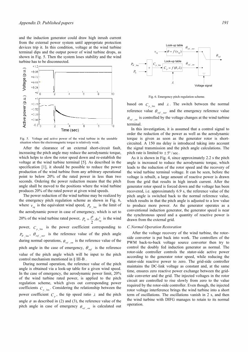
Appendix D. Published papers 191
and the induction generator could draw high inrush current from the external power system until appropriate protection devices trip it. In this condition, voltage at the wind turbine terminal dips and the output power of wind turbine drops, as shown in Fig. 5. Then the system loses stability and the wind turbine has to be disconnected.
After the clearance of an external short-circuit fault, increasing the pitch angle may reduce the aerodynamic torque, which helps to slow the rotor speed down and re-establish the voltage at the wind turbine terminal [5]. As described in the specification [1], it should be possible to reduce the power production of the wind turbine from any arbitrary operational point to below 20% of the rated power in less than two seconds. Ordering the power reduction means that the pitch angle shall be moved to the positions where the wind turbine produces 20% of the rated power at given wind speeds.
The power reduction of the wind turbine may be realized by the emergency pitch regulation scheme as shown in Fig. 6, where eqv is the equivalent wind speed,
lim_WP is the limit of
the aerodynamic power in case of emergency, which is set to 20% of the wind turbine rated power, 3
0 2 eqAvP ρ= is the wind
power, lim_pC is the power coefficient corresponding to
lim_WP , norref _θ is the reference value of the pitch angle
during normal operations, emref _θ is the reference value of the
pitch angle in the case of emergency, refθ is the reference
value of the pitch angle which will be input to the pitch control mechanism mentioned in § III-B .
During normal operation, the reference value of the pitch angle is obtained via a look-up table for a given wind speed. In the case of emergency, the aerodynamic power limit, 20% of the wind turbine rated power, is applied to the pitch regulation scheme, which gives out corresponding power coefficients
lim_pC . Considering the relationship between the
power coefficient pC , the tip speed ratio λ and the pitch
angle θ as described in (2) and (3), the reference value of the pitch angle in case of emergency
emref _θ is calculated out
based on lim_pC and λ . The switch between the normal
reference value norref _θ and the emergency reference value
emref _θ is controlled by the voltage changes at the wind turbine
terminal. In this investigation, it is assumed that a control signal to
order the reduction of the power as well as the aerodynamic torque is given as soon as the generator rotor is short-circuited. A 150 ms delay is introduced taking into account the signal transmission and the pitch angle calculations. The pitch rate is limited to sec/5°± .
As it is shown in Fig. 4, since approximately 2.2 s the pitch angle is increased to reduce the aerodynamic torque, which leads to the reduction of the rotor speed and the recovery of the wind turbine terminal voltage. It can be seen, before the voltage is rebuilt, a large amount of reactive power is drawn from the grid that results in high inrush current. After the generator rotor speed is forced down and the voltage has been recovered, i.e. approximately 6.9 s, the reference value of the pitch angle is switched back to the normal reference value, which results in that the pitch angle is adjusted to a low value to produce more power. As the generator operates as a conventional induction generator, the generator speed is near the synchronous speed and a quantity of reactive power is drawn from the external grid.
C. Normal Operation Restoration After the voltage recovery of the wind turbine, the rotor-
side converter is put back into work. The controllers of the PWM back-to-back voltage source converter then try to control the doubly fed induction generator as normal. The rotor-side controller controls the stator-side active power according to the generator rotor speed, while reducing the stator-side reactive power to zero. The grid-side controller maintains the DC-link voltage as constant and, at the same time, ensures zero reactive power exchange between the grid-side converter and the grid. The injected voltages in the rotor circuit are controlled to rise slowly from zero to the value required by the rotor-side controller. Even though, the injected rotor voltage interference brings the wind turbine into a short term of oscillations. The oscillations vanish in 2 s, and then the wind turbine with DIFG manages to retain to its normal operation.
Fig. 5. Voltage and active power of the wind turbine in the unstable situation where the electromagnetic torque is relatively weak.
eqv
Look-up table
)( eqvf=θ
lim_WP
0P÷
Look-up table
),( λθfC p =
λ
lim_pC
norref _θ
emref _θ
Voltage signal
refθ
Fig. 6. Emergency pitch regulation scheme.
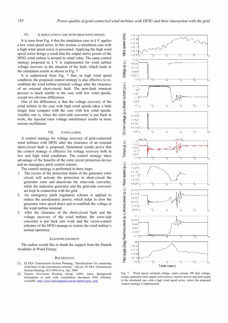
Power quality of grid-connected wind turbines with DFIG and their interaction with the grid 192
VI. A SIMULATION CASE WITH HIGH WIND SPEEDS It is seen from Fig. 4 that the simulation case in § V applies
a low wind speed series. In this section, a simulation case with a high wind speed series is presented. Applying the high wind speed series brings a result that the output active power of the DFIG wind turbine is around its rated value. The same control strategy proposed in § V is implemented for wind turbine voltage recovery in the situation of the fault, which leads to the simulation results as shown in Fig. 7.
It is understood from Fig. 7 that, in high wind speed condition, the proposed control strategy is also effective to re-establish the wind turbine terminal voltage after the clearance of an external short-circuit fault. The post-fault transient process is much similar to the case with low wind speeds, except two obvious differences.
One of the differences is that the voltage recovery of the wind turbine in the case with high wind speeds takes a little longer time compare with the case with low wind speeds. Another one is, when the rotor-side converter is put back to work, the injected rotor voltage interference results in more serious oscillations.
VII. CONCLUSION A control strategy for voltage recovery of grid-connected
wind turbines with DFIG after the clearance of an external short-circuit fault is proposed, Simulation results prove that the control strategy is effective for voltage recovery both in low and high wind conditions. The control strategy takes advantage of the benefits of the rotor circuit protection device and an emergency pitch control scheme.
The control strategy is performed in three steps: 1. The excess of the protection limits of the generator rotor
circuit will activate the protection to short-circuit the generator rotor and deactivate the rotor-side converter, while the induction generator and the grid-side converter are kept in connection with the grid.
2. An emergency pitch regulation scheme is applied to reduce the aerodynamic power, which helps to slow the generator rotor speed down and re-establish the voltage at the wind turbine terminal.
3. After the clearance of the short-circuit fault and the voltage recovery of the wind turbine, the rotor-side converter is put back into work and the vector-control schemes of the DFIG manage to restore the wind turbine’s normal operation.
ACKNOWLEDGMENT The author would like to thank the support from the Danish
Academy in Wind Energy.
REFERENCES [1] ELTRA Transmission System Planning, “Specifications for connecting
wind farms to the transmission network,” 2nd ed., ELTRA Transmission System Planning, ELT1999-411a, Apr. 2000.
[2] Generic Provisions Working Group. (2003, June). Background information to grid code consultation document D/03 [Online]. Available: http://www.nationalgrid.com/uk/indinfo/grid_code
Fig. 7. Wind speed, terminal voltage, stator current, DC-link voltage, torque, generator rotor speed, active power, reactive power and pitch angle in the simulated case with a high wind speed series, where the proposed control strategy is implemented.
Appendix D. Published papers 193
[3] V. Akhmatov, “Analysis of dynamic behaviour of electric power systems with large amount of wind power,” Ph.D dissertation, Electric Power Engineering, Technical University of Denmark, Apr. 2003.
[4] V. Akhmatov, H. Knudsen, A. H. Nielsen, N. K. Poulsen, J. K. Pedersen, “Short-term stability of large-scale wind farms,’’ in Proc. European Wind Energy Conference, Copenhagen, 2001, pp. 1182-1186.
[5] T. Sun, Z. Chen, F. Blaabjerg, “Voltage recovery of grid-connected wind turbines after a short-circuit fault,’’ in Proc. 29th Annual Conference of the IEEE Industrial Electronics Society (IECON 2003), Roanoke, 2003, pp. 2723-2728.
[6] L. Holdsworth, X.G. Wu, J.B. Ekanayake, N. Jenkins, “Comparison of fixed speed and doubly-fed induction wind turbines during power system disturbances,’’ IEE Proc. Gener. Transm. Distrib., vol. 150, no. 3, pp. 343-352, May 2003.
[7] J. Usaola, P. Ledesma, “Dynamic incidence of wind turbines in networks with high wind penetration,’’ in Proc. 2001 IEEE Power Engineering Society Summer Meeting, Vancouver, 2001, vol. 2, pp. 755-760.
[8] P. Sørensen, A. D. Hansen, P. A. C. Rosas, “Wind models for simulation of power fluctuations from wind farms,’’ Journal of Wind Engineering and Industrial Aerodynamics, vol. 90, pp. 1381-1402, Dec. 2002.
[9] P. A. C. Rosas, P. Sørensen, H. Bindner, “Fast wind modeling for wind turbines,’’ in Proc. Wind Power for the 21 Century: EUWER Special Topic Conference and Exhibition, Kassel, 2000, pp. 184-187.
[10] S. Heier, Grid integration of wind energy conversion systems, Chichester: John Wiley & Sons Ltd, 1998.
[11] J. G. Slootweg, H. Polinder, W. L. Kling, “Dynamic modeling of a wind turbine with direct drive synchronous generator and back to back voltage source converter and its control,” in Proc. European Wind Energy Conference, Copenhagen, 2001, pp. 1014-1017.
[12] P. Giroux, G. Sybille, H. Le-Huy, “Modeling and simulation of a distribution STATCOM using simulink’s power system blockset,” in Proc. 27th Annual Conference of the IEEE Industrial Electronics Society, Denver, 2001, vol. 2, pp. 990-994.
[13] R. Pena, J. C. Clare, G. M. Asher, “DFIG using back-to-back PWM converters and its application to variable-speed wind-energy generation,” IEE Proc. Electr. Power Appl., vol. 143, no. 3, pp. 231-241, May 1996.
[14] J. F. Manwell, J. G. McGowan, A. L. Rogers, Wind energy explained: theory, design and application, Chichester: John Wiley & Sons Ltd, 2002.

Power quality of grid-connected wind turbines with DFIG and their interaction with the grid 194
Appendix D. Published papers 195
Abstract—Grid connected wind turbines may produce flicker
during continuous operation. This paper presents a simulation model of a MW-level variable speed wind turbine with a doubly fed induction generator developed in the simulation tool of PSCAD/EMTDC. Flicker emission of variable speed wind turbines with doubly fed induction generators is investigated during continuous operation, and the dependence of flicker emission on mean wind speed, wind turbulence intensity, short circuit capacity of grid and grid impedance angle are analyzed. A comparison is done with the fixed speed wind turbine, which leads to a conclusion that the factors mentioned above have different influences on flicker emission compared with that in the case of the fixed speed wind turbine. Flicker mitigation is realized by output reactive power control of the variable speed wind turbine with doubly fed induction generator. Simulation results show the wind turbine output reactive power control provides an effective means for flicker mitigation regardless of mean wind speed, turbulence intensity and short circuit capacity ratio.
Index Terms—Doubly fed induction generator, flicker, variable speed wind turbine.
I. INTRODUCTION N recent years wind power generation has experienced a very fast development in the whole world. As the wind power penetration into the grid is increasing quickly, the
influence of wind turbines on the power quality is becoming an important issue. One of the important power quality aspects is flicker.
Flicker is defined as “an impression of unsteadiness of visual sensation induced by a light stimulus, whose luminance or spectral distribution fluctuates with time”[1], which can cause consumer annoyance and complaint. Furthermore, flicker can become a limiting factor for integrating wind turbines into weak grids, and even into relatively strong grids where the wind power penetration levels are high. Flicker is induced by voltage fluctuations, which are caused
T. Sun is with North China Electric Power University and China Electric
Power Research Institute. Currently he is with the Institute of Energy Technology, Aalborg University, DK-9220 Aalborg, Denmark (e-mail: [email protected]).
Z. Chen is with the Institute of Energy Technology, Aalborg University, DK-9220 Aalborg, Denmark (e-mail: [email protected]), on leave from De Montfort University, Leicester, UK.
F. Blaabjerg is with the Institute of Energy Technology, Aalborg University, DK-9220 Aalborg, Denmark (e-mail: fbl@iet. aau.dk).
by load flow changes in the grid. Grid connected wind turbines may have considerable fluctuations in output power, which depend on the wind power generation technology applied. The flicker emission produced by grid connected wind turbines during continuous operation is mainly caused by fluctuations in the output power due to wind speed variations, the wind gradient and the tower shadow effect [2]. As a consequence of the combination of wind speed variations, the wind gradient and the tower shadow effect, an output power drop will appear three times per revolution for a three-bladed wind turbine. This frequency is normally referred to as the p3 frequency. For fixed speed wind turbines with induction generators, power pulsations up to 20% of the average power at the frequency of p3 will be generated [3]. There are numerous of factors that affect flicker emission of grid-connected wind turbines during continuous operation, such as wind characteristics (e.g. mean wind speed, turbulence intensity) and grid conditions (e.g. short circuit capacity, grid impedance angle, load type) [2], [4], [5], [6], [7]. The type of wind turbine also has influence on flicker emission. Variable speed wind turbines have shown better performance related to flicker emission in comparison with fixed speed wind turbines [2], [4]. The reason is that variable speed operation of the rotor has the advantage that the faster power variations are not transmitted to the grid but are smoothed by the flywheel action of the rotor.
Although the variable speed wind turbine produces lower flicker levels, the flicker study becomes necessary and imperative as the wind power penetration level increases quickly. Variable speed wind turbines with doubly fed induction generators, the most popular installed variable speed wind turbines worldwide [8], [9] are the main research topic in this paper. In this paper, a simulation model of a MW-level variable speed wind turbine with a doubly fed induction generator developed in PSCAD/EMTDC [10], [11] is presented, and the control schemes of the wind turbine are described. Based on the wind turbine model, flicker emission of variable speed wind turbines with doubly fed induction generators is investigated during continuous operation. The factors that affect flicker emission of wind turbines, such as wind characteristics (mean speed, turbulence intensity) and grid conditions (short circuit capacity, grid impedance angle) are analyzed. Compared with that in the case of the fixed speed wind turbine, the factors mentioned above have different influences on flicker emission of the variable speed wind
Tao Sun, Zhe Chen, Senior Member, IEEE, Frede Blaabjerg, Fellow, IEEE
Flicker Study on Variable Speed Wind Turbines with Doubly Fed Induction Generators
I
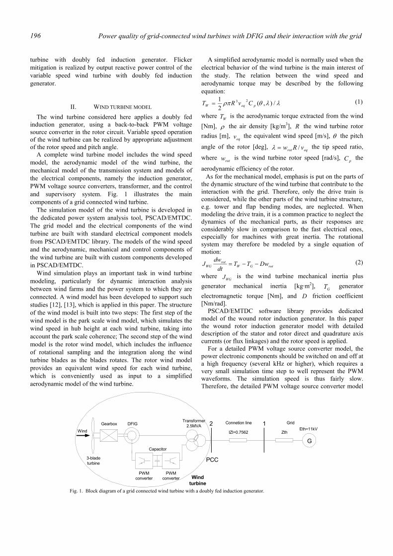
Power quality of grid-connected wind turbines with DFIG and their interaction with the grid 196
turbine with doubly fed induction generator. Flicker mitigation is realized by output reactive power control of the variable speed wind turbine with doubly fed induction generator.
II. WIND TURBINE MODEL The wind turbine considered here applies a doubly fed
induction generator, using a back-to-back PWM voltage source converter in the rotor circuit. Variable speed operation of the wind turbine can be realized by appropriate adjustment of the rotor speed and pitch angle.
A complete wind turbine model includes the wind speed model, the aerodynamic model of the wind turbine, the mechanical model of the transmission system and models of the electrical components, namely the induction generator, PWM voltage source converters, transformer, and the control and supervisory system. Fig. 1 illustrates the main components of a grid connected wind turbine.
The simulation model of the wind turbine is developed in the dedicated power system analysis tool, PSCAD/EMTDC. The grid model and the electrical components of the wind turbine are built with standard electrical component models from PSCAD/EMTDC library. The models of the wind speed and the aerodynamic, mechanical and control components of the wind turbine are built with custom components developed in PSCAD/EMTDC.
Wind simulation plays an important task in wind turbine modeling, particularly for dynamic interaction analysis between wind farms and the power system to which they are connected. A wind model has been developed to support such studies [12], [13], which is applied in this paper. The structure of the wind model is built into two steps: The first step of the wind model is the park scale wind model, which simulates the wind speed in hub height at each wind turbine, taking into account the park scale coherence; The second step of the wind model is the rotor wind model, which includes the influence of rotational sampling and the integration along the wind turbine blades as the blades rotates. The rotor wind model provides an equivalent wind speed for each wind turbine, which is conveniently used as input to a simplified aerodynamic model of the wind turbine.
A simplified aerodynamic model is normally used when the electrical behavior of the wind turbine is the main interest of the study. The relation between the wind speed and aerodynamic torque may be described by the following equation:
λλθρπ /),(21 23
peqW CvRT = (1)
where WT is the aerodynamic torque extracted from the wind [Nm], ρ the air density [kg/m3], R the wind turbine rotor radius [m], eqv the equivalent wind speed [m/s], θ the pitch
angle of the rotor [deg], eqrot vRw /=λ the tip speed ratio,
where rotw is the wind turbine rotor speed [rad/s], pC the
aerodynamic efficiency of the rotor. As for the mechanical model, emphasis is put on the parts of
the dynamic structure of the wind turbine that contribute to the interaction with the grid. Therefore, only the drive train is considered, while the other parts of the wind turbine structure, e.g. tower and flap bending modes, are neglected. When modeling the drive train, it is a common practice to neglect the dynamics of the mechanical parts, as their responses are considerably slow in comparison to the fast electrical ones, especially for machines with great inertia. The rotational system may therefore be modeled by a single equation of motion:
rotGWrot
WG DwTTdt
dwJ −−= (2)
where WGJ is the wind turbine mechanical inertia plus generator mechanical inertia [kg·m2], GT generator electromagnetic torque [Nm], and D friction coefficient [Nm/rad].
PSCAD/EMTDC software library provides dedicated model of the wound rotor induction generator. In this paper the wound rotor induction generator model with detailed description of the stator and rotor direct and quadrature axis currents (or flux linkages) and the rotor speed is applied.
For a detailed PWM voltage source converter model, the power electronic components should be switched on and off at a high frequency (several kHz or higher), which requires a very small simulation time step to well represent the PWM waveforms. The simulation speed is thus fairly slow. Therefore, the detailed PWM voltage source converter model
3-bladeturbine
GearboxTransformer
2.5MVA
GlZl=0.7562 Zth
Eth=11kV2 1
Wind
DFIG
Capacitor
PWMconverter
PWMconverter Wind
turbine
PCC
Connetion line Grid
Fig. 1. Block diagram of a grid connected wind turbine with a doubly fed induction generator.
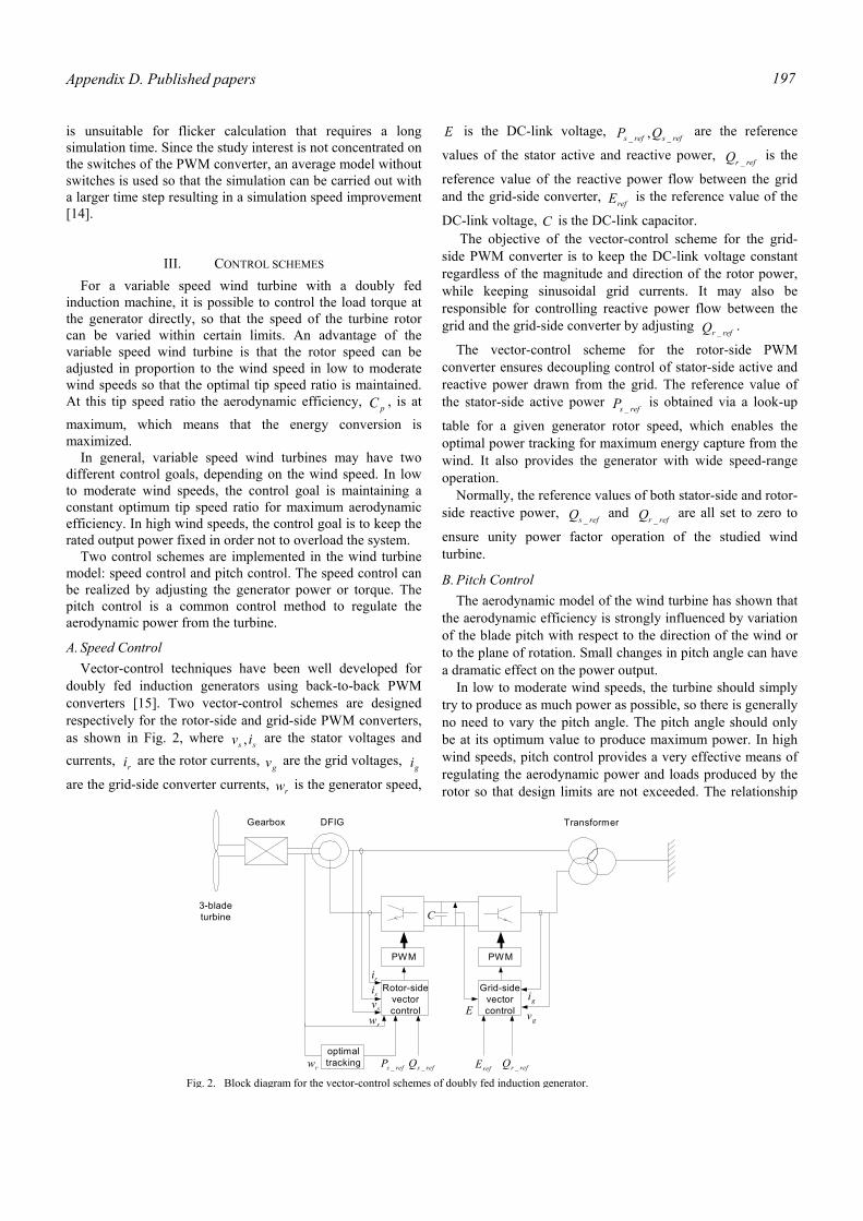
Appendix D. Published papers 197
is unsuitable for flicker calculation that requires a long simulation time. Since the study interest is not concentrated on the switches of the PWM converter, an average model without switches is used so that the simulation can be carried out with a larger time step resulting in a simulation speed improvement [14].
III. CONTROL SCHEMES For a variable speed wind turbine with a doubly fed
induction machine, it is possible to control the load torque at the generator directly, so that the speed of the turbine rotor can be varied within certain limits. An advantage of the variable speed wind turbine is that the rotor speed can be adjusted in proportion to the wind speed in low to moderate wind speeds so that the optimal tip speed ratio is maintained. At this tip speed ratio the aerodynamic efficiency, pC , is at
maximum, which means that the energy conversion is maximized.
In general, variable speed wind turbines may have two different control goals, depending on the wind speed. In low to moderate wind speeds, the control goal is maintaining a constant optimum tip speed ratio for maximum aerodynamic efficiency. In high wind speeds, the control goal is to keep the rated output power fixed in order not to overload the system.
Two control schemes are implemented in the wind turbine model: speed control and pitch control. The speed control can be realized by adjusting the generator power or torque. The pitch control is a common control method to regulate the aerodynamic power from the turbine.
A. Speed Control Vector-control techniques have been well developed for
doubly fed induction generators using back-to-back PWM converters [15]. Two vector-control schemes are designed respectively for the rotor-side and grid-side PWM converters, as shown in Fig. 2, where ss iv , are the stator voltages and currents, ri are the rotor currents,
gv are the grid voltages, gi
are the grid-side converter currents, rw is the generator speed,
E is the DC-link voltage, refsrefs QP __ , are the reference
values of the stator active and reactive power, refrQ _
is the
reference value of the reactive power flow between the grid and the grid-side converter,
refE is the reference value of the
DC-link voltage, C is the DC-link capacitor. The objective of the vector-control scheme for the grid-
side PWM converter is to keep the DC-link voltage constant regardless of the magnitude and direction of the rotor power, while keeping sinusoidal grid currents. It may also be responsible for controlling reactive power flow between the grid and the grid-side converter by adjusting
refrQ _.
The vector-control scheme for the rotor-side PWM converter ensures decoupling control of stator-side active and reactive power drawn from the grid. The reference value of the stator-side active power
refsP _ is obtained via a look-up
table for a given generator rotor speed, which enables the optimal power tracking for maximum energy capture from the wind. It also provides the generator with wide speed-range operation.
Normally, the reference values of both stator-side and rotor-side reactive power,
refsQ _ and
refrQ _ are all set to zero to
ensure unity power factor operation of the studied wind turbine.
B. Pitch Control The aerodynamic model of the wind turbine has shown that
the aerodynamic efficiency is strongly influenced by variation of the blade pitch with respect to the direction of the wind or to the plane of rotation. Small changes in pitch angle can have a dramatic effect on the power output.
In low to moderate wind speeds, the turbine should simply try to produce as much power as possible, so there is generally no need to vary the pitch angle. The pitch angle should only be at its optimum value to produce maximum power. In high wind speeds, pitch control provides a very effective means of regulating the aerodynamic power and loads produced by the rotor so that design limits are not exceeded. The relationship
PWM PWM
Rotor-sidevectorcontrol
Grid-sidevectorcontrol
gi
gvE
risisv
rw
optimaltracking refsP _ refsQ _ refE refrQ _
3-bladeturbine
Gearbox DFIG Transformer
C
rw
Fig. 2. Block diagram for the vector-control schemes of doubly fed induction generator.
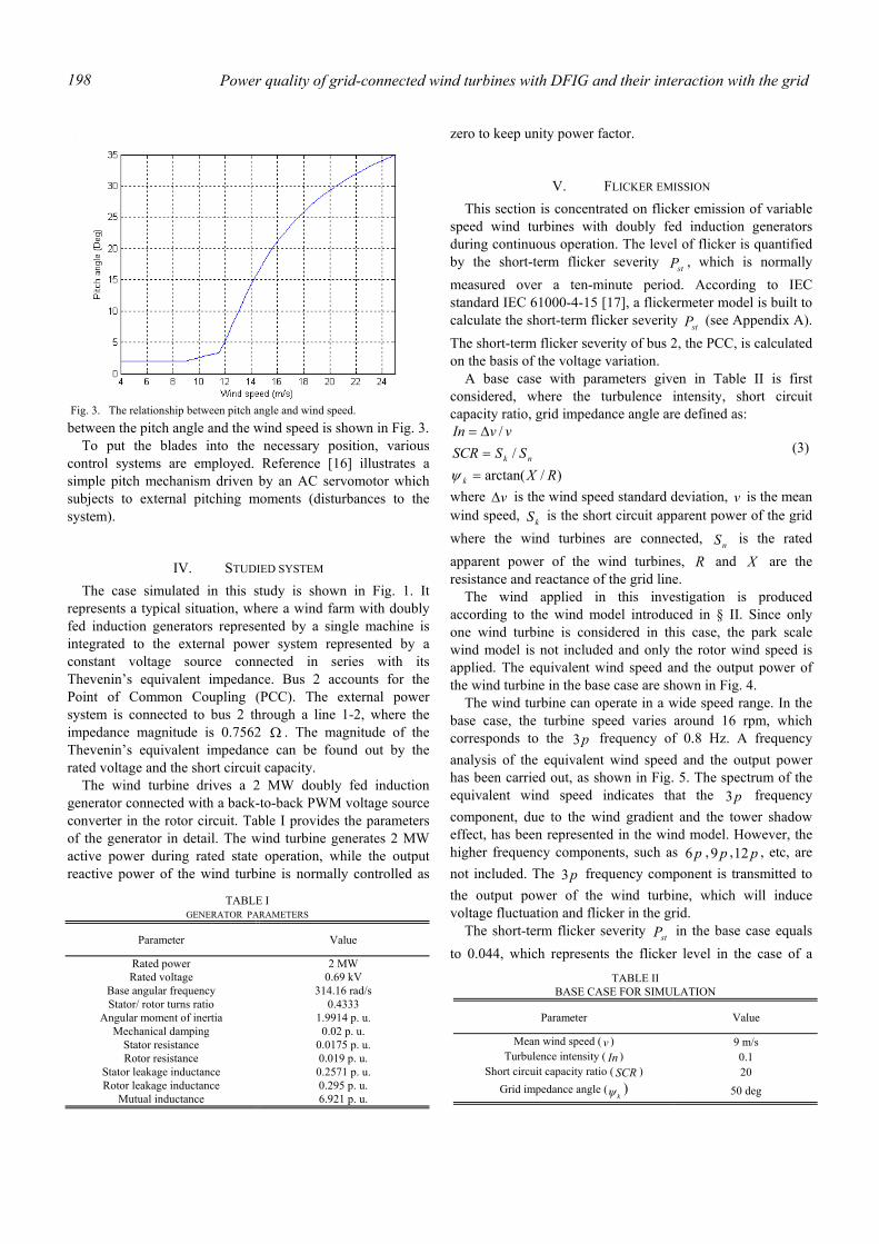
Power quality of grid-connected wind turbines with DFIG and their interaction with the grid 198
between the pitch angle and the wind speed is shown in Fig. 3. To put the blades into the necessary position, various
control systems are employed. Reference [16] illustrates a simple pitch mechanism driven by an AC servomotor which subjects to external pitching moments (disturbances to the system).
IV. STUDIED SYSTEM The case simulated in this study is shown in Fig. 1. It
represents a typical situation, where a wind farm with doubly fed induction generators represented by a single machine is integrated to the external power system represented by a constant voltage source connected in series with its Thevenin’s equivalent impedance. Bus 2 accounts for the Point of Common Coupling (PCC). The external power system is connected to bus 2 through a line 1-2, where the impedance magnitude is 0.7562 Ω . The magnitude of the Thevenin’s equivalent impedance can be found out by the rated voltage and the short circuit capacity.
The wind turbine drives a 2 MW doubly fed induction generator connected with a back-to-back PWM voltage source converter in the rotor circuit. Table I provides the parameters of the generator in detail. The wind turbine generates 2 MW active power during rated state operation, while the output reactive power of the wind turbine is normally controlled as
zero to keep unity power factor.
V. FLICKER EMISSION This section is concentrated on flicker emission of variable
speed wind turbines with doubly fed induction generators during continuous operation. The level of flicker is quantified by the short-term flicker severity stP , which is normally measured over a ten-minute period. According to IEC standard IEC 61000-4-15 [17], a flickermeter model is built to calculate the short-term flicker severity stP (see Appendix A). The short-term flicker severity of bus 2, the PCC, is calculated on the basis of the voltage variation.
A base case with parameters given in Table II is first considered, where the turbulence intensity, short circuit capacity ratio, grid impedance angle are defined as:
)/arctan(/
/
RXSSSCR
vvIn
k
nk
==∆=
ψ
(3)
where v∆ is the wind speed standard deviation, v is the mean wind speed, kS is the short circuit apparent power of the grid where the wind turbines are connected, nS is the rated apparent power of the wind turbines, R and X are the resistance and reactance of the grid line.
The wind applied in this investigation is produced according to the wind model introduced in § II. Since only one wind turbine is considered in this case, the park scale wind model is not included and only the rotor wind speed is applied. The equivalent wind speed and the output power of the wind turbine in the base case are shown in Fig. 4. The wind turbine can operate in a wide speed range. In the base case, the turbine speed varies around 16 rpm, which corresponds to the p3 frequency of 0.8 Hz. A frequency analysis of the equivalent wind speed and the output power has been carried out, as shown in Fig. 5. The spectrum of the equivalent wind speed indicates that the p3 frequency component, due to the wind gradient and the tower shadow effect, has been represented in the wind model. However, the higher frequency components, such as p6 , p9 , p12 , etc, are not included. The p3 frequency component is transmitted to the output power of the wind turbine, which will induce voltage fluctuation and flicker in the grid.
The short-term flicker severity stP in the base case equals to 0.044, which represents the flicker level in the case of a
Fig. 3. The relationship between pitch angle and wind speed.
TABLE I GENERATOR PARAMETERS
Parameter Value
Rated power 2 MW Rated voltage 0.69 kV
Base angular frequency 314.16 rad/s Stator/ rotor turns ratio 0.4333
Angular moment of inertia 1.9914 p. u. Mechanical damping 0.02 p. u.
Stator resistance 0.0175 p. u. Rotor resistance 0.019 p. u.
Stator leakage inductance 0.2571 p. u. Rotor leakage inductance 0.295 p. u.
Mutual inductance 6.921 p. u.
TABLE II BASE CASE FOR SIMULATION
Parameter Value
Mean wind speed ( v ) 9 m/s Turbulence intensity ( In ) 0.1
Short circuit capacity ratio ( SCR ) 20 Grid impedance angle (
kψ ) 50 deg
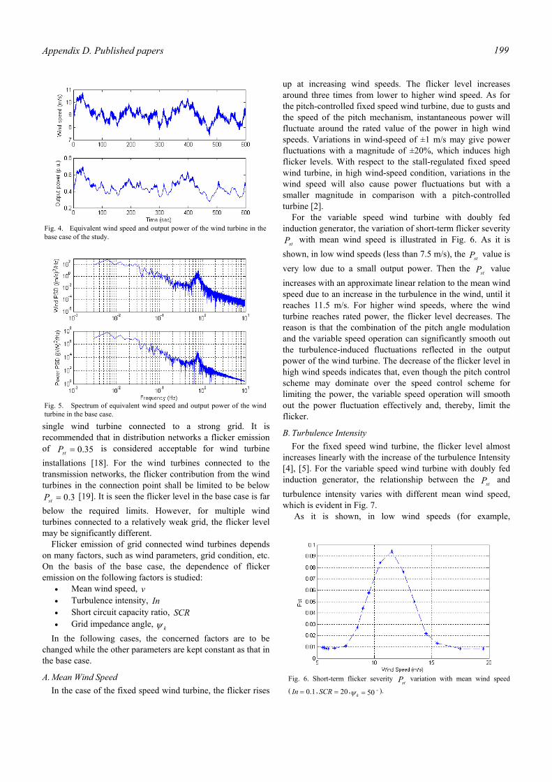
Appendix D. Published papers 199
single wind turbine connected to a strong grid. It is recommended that in distribution networks a flicker emission of 35.0=stP is considered acceptable for wind turbine installations [18]. For the wind turbines connected to the transmission networks, the flicker contribution from the wind turbines in the connection point shall be limited to be below
3.0=stP [19]. It is seen the flicker level in the base case is far below the required limits. However, for multiple wind turbines connected to a relatively weak grid, the flicker level may be significantly different. Flicker emission of grid connected wind turbines depends on many factors, such as wind parameters, grid condition, etc. On the basis of the base case, the dependence of flicker emission on the following factors is studied:
• Mean wind speed, v • Turbulence intensity, In • Short circuit capacity ratio, SCR • Grid impedance angle, kψ
In the following cases, the concerned factors are to be changed while the other parameters are kept constant as that in the base case.
A. Mean Wind Speed In the case of the fixed speed wind turbine, the flicker rises
up at increasing wind speeds. The flicker level increases around three times from lower to higher wind speed. As for the pitch-controlled fixed speed wind turbine, due to gusts and the speed of the pitch mechanism, instantaneous power will fluctuate around the rated value of the power in high wind speeds. Variations in wind-speed of ±1 m/s may give power fluctuations with a magnitude of ±20%, which induces high flicker levels. With respect to the stall-regulated fixed speed wind turbine, in high wind-speed condition, variations in the wind speed will also cause power fluctuations but with a smaller magnitude in comparison with a pitch-controlled turbine [2].
For the variable speed wind turbine with doubly fed induction generator, the variation of short-term flicker severity
stP with mean wind speed is illustrated in Fig. 6. As it is shown, in low wind speeds (less than 7.5 m/s), the stP value is very low due to a small output power. Then the stP value increases with an approximate linear relation to the mean wind speed due to an increase in the turbulence in the wind, until it reaches 11.5 m/s. For higher wind speeds, where the wind turbine reaches rated power, the flicker level decreases. The reason is that the combination of the pitch angle modulation and the variable speed operation can significantly smooth out the turbulence-induced fluctuations reflected in the output power of the wind turbine. The decrease of the flicker level in high wind speeds indicates that, even though the pitch control scheme may dominate over the speed control scheme for limiting the power, the variable speed operation will smooth out the power fluctuation effectively and, thereby, limit the flicker.
B. Turbulence Intensity For the fixed speed wind turbine, the flicker level almost
increases linearly with the increase of the turbulence Intensity [4], [5]. For the variable speed wind turbine with doubly fed induction generator, the relationship between the stP and turbulence intensity varies with different mean wind speed, which is evident in Fig. 7.
As it is shown, in low wind speeds (for example,
Fig. 4. Equivalent wind speed and output power of the wind turbine in thebase case of the study.
Fig. 5. Spectrum of equivalent wind speed and output power of the windturbine in the base case.
Fig. 6. Short-term flicker severity stP variation with mean wind speed
( 1.0=In , 20=SCR , o50=kψ ).

Power quality of grid-connected wind turbines with DFIG and their interaction with the grid 200
smv /9= ), the stP has an almost linear relation with the turbulence intensity. The more turbulence in the wind results in larger flicker emission. However, in high wind speeds (for example, smv /18= ), where the wind turbine is controlled to keep the rated output power, the relationship between the stP and turbulence intensity is quite different. When the turbulence intensity of the wind is low, the wind profile varies in a small range that corresponds to a rated output power. The
stP value is low due to a small power fluctuation as a result of the aerodynamic regulation. As the turbulence intensity increases, the wind profile changes significantly which results in a large variation of output power. As a consequence, the flicker emission becomes serious. The equivalent wind speeds and output power fluctuations for different turbulence intensity values are demonstrated in Fig. 8 and Fig. 9 respectively.
C. Short Circuit Capacity Ratio In the case of variable speed wind turbine with doubly fed
induction generator, Fig. 10 illustrates an approximately inversely proportional relationship between the short-term flicker severity stP and the short circuit capacity ratio. This relationship also applies to the fixed speed wind turbine [2], [4], [6]. The higher the short circuit capacity ratio, the stronger the grid where the wind turbine is connected. As expected, the wind turbine would produce greater flicker in weak grids than in stronger grids.
D. Grid impedance Angle The voltage change across a power line may be
approximately calculated with the following formula [20]:
VQXPRV +
=∆ (4)
where P and Q are the active and reactive power flow on the line respectively, R and X are the resistance and reactance of the grid line, and V is the voltage at the line terminal. The grid impedance angle is so important that the voltage changes from the active power flow may be cancelled by that from the reactive power flow. The determining factor is the difference between the grid impedance angle kψ and the power factor angle ψ that the wind energy conversion system is operating at [4]. When the difference approaches 90 degrees, the flicker emission is minimized.
The fixed speed wind turbine absorbs reactive power from the grid while it is generating active power. For the operating condition with fixed speed wind turbine, the minimum flicker emission occurs at a grid impedance angle between 60 to 70 degrees [4], [6]. The situation becomes different in the case of variable speed wind turbine with doubly fed induction generator, which is capable of controlling the output active and reactive power. Normally the variable speed wind turbine with doubly fed induction generator is controlled to operate at unity power factor, which means no reactive power is injected into or drawn from the grid. In this case, the resistance value of the grid line is the determining factor that affects the flicker emission from the wind turbine. When the grid impedance angle increases, the resistance value decreases which results in reduced flicker emission, as shown in Fig. 11. If the output power of the wind turbine follows a QP − curve, as shown in Fig. 12, the reactive power will contribute to the flicker emission. The curve shown in Fig. 12 represents
Fig. 7. Short-term flicker severity stP variation with turbulence intensity
( smv /9= (asterisk), smv /18= (diamond), 20=SCR , o50=kψ ).
Fig. 9. The output power for different turbulence intensity values.
Fig. 8. The wind speeds for different turbulence intensity values.
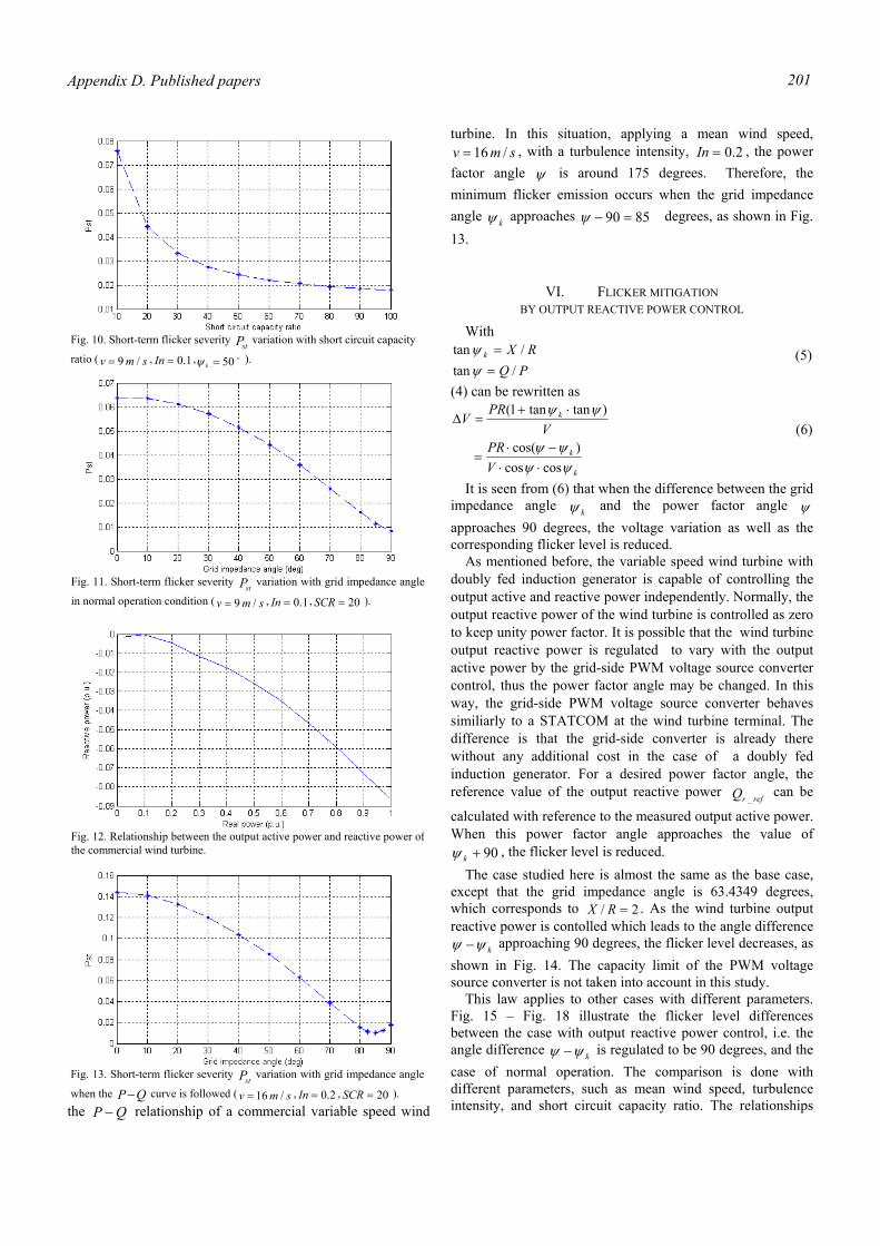
Appendix D. Published papers 201
the QP − relationship of a commercial variable speed wind
turbine. In this situation, applying a mean wind speed, smv /16= , with a turbulence intensity, 2.0=In , the power
factor angle ψ is around 175 degrees. Therefore, the minimum flicker emission occurs when the grid impedance angle kψ approaches 8590 =−ψ degrees, as shown in Fig. 13.
VI. FLICKER MITIGATION BY OUTPUT REACTIVE POWER CONTROL
With
PQRXk
/tan/tan
==
ψψ (5)
(4) can be rewritten as
k
k
k
VPR
VPR
V
ψψψψ
ψψ
coscos)cos(
)tantan1(
⋅⋅−⋅
=
⋅+=∆
(6)
It is seen from (6) that when the difference between the grid impedance angle kψ and the power factor angle ψ approaches 90 degrees, the voltage variation as well as the corresponding flicker level is reduced.
As mentioned before, the variable speed wind turbine with doubly fed induction generator is capable of controlling the output active and reactive power independently. Normally, the output reactive power of the wind turbine is controlled as zero to keep unity power factor. It is possible that the wind turbine output reactive power is regulated to vary with the output active power by the grid-side PWM voltage source converter control, thus the power factor angle may be changed. In this way, the grid-side PWM voltage source converter behaves similiarly to a STATCOM at the wind turbine terminal. The difference is that the grid-side converter is already there without any additional cost in the case of a doubly fed induction generator. For a desired power factor angle, the reference value of the output reactive power
refrQ _ can be
calculated with reference to the measured output active power. When this power factor angle approaches the value of
90+kψ , the flicker level is reduced. The case studied here is almost the same as the base case,
except that the grid impedance angle is 63.4349 degrees, which corresponds to 2/ =RX . As the wind turbine output reactive power is contolled which leads to the angle difference
kψψ − approaching 90 degrees, the flicker level decreases, as shown in Fig. 14. The capacity limit of the PWM voltage source converter is not taken into account in this study.
This law applies to other cases with different parameters. Fig. 15 – Fig. 18 illustrate the flicker level differences between the case with output reactive power control, i.e. the angle difference kψψ − is regulated to be 90 degrees, and the case of normal operation. The comparison is done with different parameters, such as mean wind speed, turbulence intensity, and short circuit capacity ratio. The relationships
Fig. 10. Short-term flicker severity
stP variation with short circuit capacity
ratio ( smv /9= , 1.0=In , o50=kψ ).
Fig. 11. Short-term flicker severity stP variation with grid impedance angle
in normal operation condition ( smv /9= , 1.0=In , 20=SCR ).
Fig. 12. Relationship between the output active power and reactive power ofthe commercial wind turbine.
Fig. 13. Short-term flicker severity stP variation with grid impedance angle
when the QP − curve is followed ( smv /16= , 2.0=In , 20=SCR ).
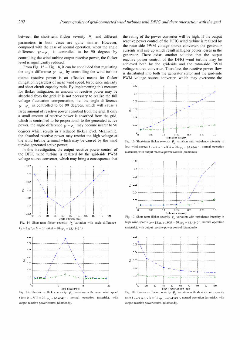
Power quality of grid-connected wind turbines with DFIG and their interaction with the grid 202
between the short-term flicker severity stP and different parameters in both cases are quite similar. However, compared with the case of normal operation, when the angle difference kψψ − is controlled to be 90 degrees by controlling the wind turbine output reactive power, the flicker level is significantly reduced.
From Fig. 15 – Fig. 18, it can be concluded that regulating the angle difference kψψ − by controlling the wind turbine output reactive power is an effective means for flicker mitigation regardless of mean wind speed, turbulence intensity and short circuit capacity ratio. By implementing this measure for flicker mitigation, an amount of reactive power may be absorbed from the grid. It is not necessary to realize the full voltage fluctuation compensation, i.e. the angle difference
kψψ − is controlled to be 90 degrees, which will cause a large amount of reactive power absorbed from the grid. If only a small amount of reactive power is absorbed from the grid, which is controlled to be proportional to the generated active power, the angle difference kψψ − may become nearer to 90 degrees which results in a reduced flicker level. Meanwhile, the absorbed reactive power may restrict the high voltage at the wind turbine terminal which may be caused by the wind turbine generated active power.
In this investigation, the output reactive power control of the DFIG wind turbine is realized by the grid-side PWM voltage source converter, which may bring a consequence that
the rating of the power converter will be high. If the output reactive power control of the DFIG wind turbine is realized by the rotor-side PWM voltage source converter, the generator currents will rise up which result in higher power losses in the generator. There exists another solution that the output reactive power control of the DFIG wind turbine may be achieved both by the grid-side and the rotor-side PWM voltage source converter. Therefore, the reactive power flow is distributed into both the generator stator and the grid-side PWM voltage source converter, which may overcome the
Fig. 14. Short-term flicker severity stP variation with angle difference
( smv /9= , 1.0=In , 20=SCR , o4349.63=kψ ).
Fig. 15. Short-term flicker severity stP variation with mean wind speed
( 1.0=In , 20=SCR , o4349.63=kψ , normal operation (asterisk), with
output reactive power control (diamond)).
Fig. 16. Short-term flicker severity stP variation with turbulence intensity in
low wind speeds ( smv /9= , 20=SCR , o4349.63=kψ , normal operation
(asterisk), with output reactive power control (diamond)).
Fig. 17. Short-term flicker severity stP variation with turbulence intensity in
high wind speeds ( smv /18= , 20=SCR , o4349.63=kψ , normal operation
(asterisk), with output reactive power control (diamond)).
Fig. 18. Short-term flicker severity stP variation with short circuit capacity
ratio ( smv /9= , 1.0=In , o4349.63=kψ , normal operation (asterisk), with
output reactive power control (diamond)).
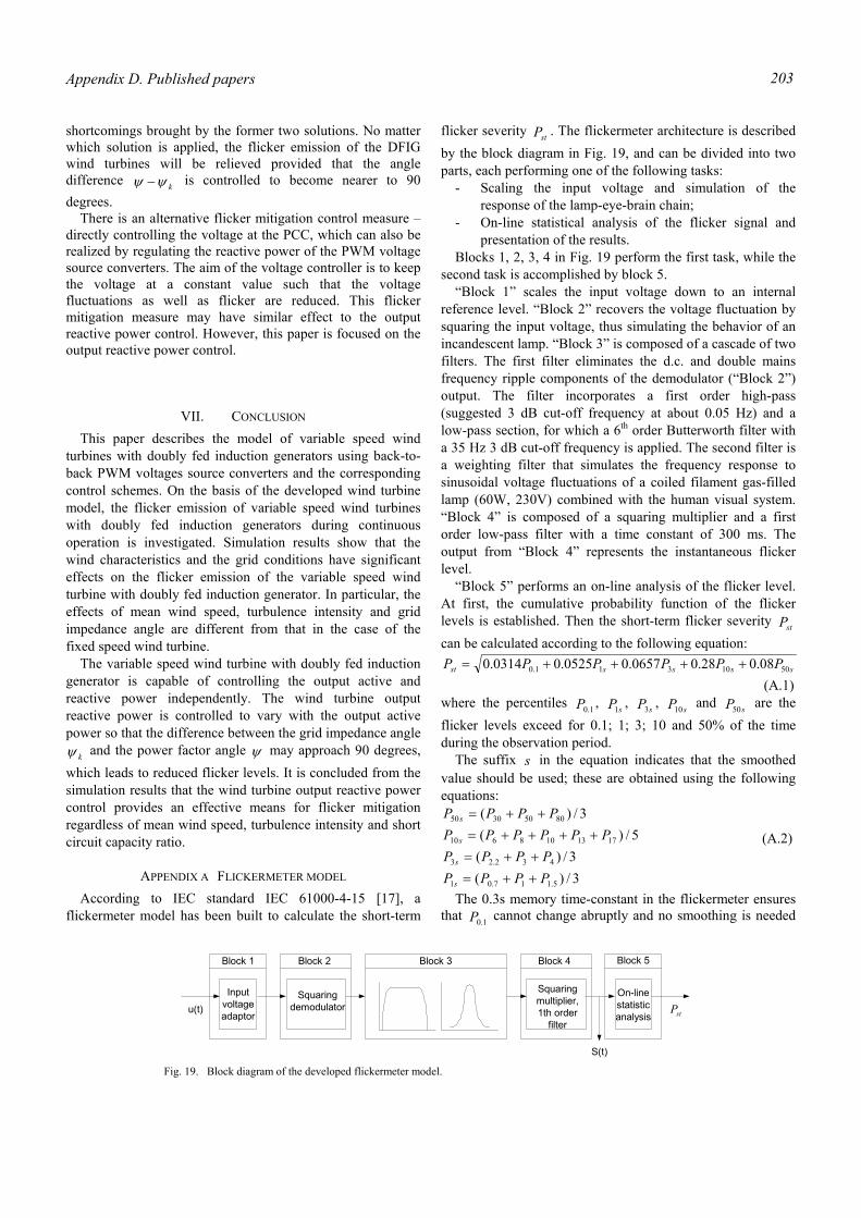
Appendix D. Published papers 203
shortcomings brought by the former two solutions. No matter which solution is applied, the flicker emission of the DFIG wind turbines will be relieved provided that the angle difference kψψ − is controlled to become nearer to 90 degrees.
There is an alternative flicker mitigation control measure – directly controlling the voltage at the PCC, which can also be realized by regulating the reactive power of the PWM voltage source converters. The aim of the voltage controller is to keep the voltage at a constant value such that the voltage fluctuations as well as flicker are reduced. This flicker mitigation measure may have similar effect to the output reactive power control. However, this paper is focused on the output reactive power control.
VII. CONCLUSION This paper describes the model of variable speed wind
turbines with doubly fed induction generators using back-to-back PWM voltages source converters and the corresponding control schemes. On the basis of the developed wind turbine model, the flicker emission of variable speed wind turbines with doubly fed induction generators during continuous operation is investigated. Simulation results show that the wind characteristics and the grid conditions have significant effects on the flicker emission of the variable speed wind turbine with doubly fed induction generator. In particular, the effects of mean wind speed, turbulence intensity and grid impedance angle are different from that in the case of the fixed speed wind turbine.
The variable speed wind turbine with doubly fed induction generator is capable of controlling the output active and reactive power independently. The wind turbine output reactive power is controlled to vary with the output active power so that the difference between the grid impedance angle
kψ and the power factor angle ψ may approach 90 degrees, which leads to reduced flicker levels. It is concluded from the simulation results that the wind turbine output reactive power control provides an effective means for flicker mitigation regardless of mean wind speed, turbulence intensity and short circuit capacity ratio.
APPENDIX A FLICKERMETER MODEL According to IEC standard IEC 61000-4-15 [17], a
flickermeter model has been built to calculate the short-term
flicker severity stP . The flickermeter architecture is described by the block diagram in Fig. 19, and can be divided into two parts, each performing one of the following tasks:
- Scaling the input voltage and simulation of the response of the lamp-eye-brain chain;
- On-line statistical analysis of the flicker signal and presentation of the results.
Blocks 1, 2, 3, 4 in Fig. 19 perform the first task, while the second task is accomplished by block 5.
“Block 1” scales the input voltage down to an internal reference level. “Block 2” recovers the voltage fluctuation by squaring the input voltage, thus simulating the behavior of an incandescent lamp. “Block 3” is composed of a cascade of two filters. The first filter eliminates the d.c. and double mains frequency ripple components of the demodulator (“Block 2”) output. The filter incorporates a first order high-pass (suggested 3 dB cut-off frequency at about 0.05 Hz) and a low-pass section, for which a 6th order Butterworth filter with a 35 Hz 3 dB cut-off frequency is applied. The second filter is a weighting filter that simulates the frequency response to sinusoidal voltage fluctuations of a coiled filament gas-filled lamp (60W, 230V) combined with the human visual system. “Block 4” is composed of a squaring multiplier and a first order low-pass filter with a time constant of 300 ms. The output from “Block 4” represents the instantaneous flicker level.
“Block 5” performs an on-line analysis of the flicker level. At first, the cumulative probability function of the flicker levels is established. Then the short-term flicker severity stP can be calculated according to the following equation:
ssssst PPPPPP 5010311.0 08.028.00657.00525.00314.0 ++++= (A.1) where the percentiles 1.0P , sP1 , sP3 , sP10 and sP50 are the flicker levels exceed for 0.1; 1; 3; 10 and 50% of the time during the observation period. The suffix s in the equation indicates that the smoothed value should be used; these are obtained using the following equations:
3/)(3/)(
5/)(3/)(
5.117.01
432.23
1713108610
80503050
PPPPPPPP
PPPPPPPPPP
s
s
s
s
++=++=
++++=++=
(A.2)
The 0.3s memory time-constant in the flickermeter ensures that 1.0P cannot change abruptly and no smoothing is needed
Inputvoltageadaptor
Squaringdemodulator
Squaringmultiplier,1th order
filter
On-linestatisticanalysis
Block 1 Block 5Block 4Block 3Block 2
u(t)
S(t)
stP
Fig. 19. Block diagram of the developed flickermeter model.
Power quality of grid-connected wind turbines with DFIG and their interaction with the grid 204
for this percentile.
REFERENCES [1] L. Rossetto, P. Tenti, A. Zuccato, “Electromagnetic compatibility issues
in industrial equipment,” IEEE Industry Application Magazine, vol. 5, Issue. 6, pp. 34-46, Nov/Dec 1999.
[2] Åke Larsson, “Flicker emission of wind turbines during continuous operation,” IEEE Trans. Energy Conversion, vol. 17, no. 1, pp. 114-118, March 2002.
[3] G. Gerdes, F. Santjer, “Power quality of wind turbines and their interaction with the grid,” in Proc. Euro. Wind Energy Conf., Thessaloniki, Greece, Oct. 10-14, 1994, pp. 1112-1115.
[4] M.P. Papadopoulos, S.A. Papathanassiou, S.T. Tentzerakis, N.G. Boulaxis, “Investigation of the flicker emission by grid connected wind turbines,” in Proc. 8th International Conference on Harmonics And Quality of Power, Athens, Greece, 14-16 Oct 1998, vol. 2, pp: 1152 -1157.
[5] P.D. Ladakakos, M.G. Ioannides, M.I. Koulouvari, “Assessment of wind turbines impact on the power quality of autonomous weak grids,” in Proc. 8th International Conference on Harmonics and Quality of Power, Athens, Greece, 14-16 Oct 1998, vol. 2, pp. 900-905.
[6] H. Amarís, C. Vilar, J. Usaola, J.L. Rodríguez, “Frequency domain analysis of flicker produced by wind energy conversions systems,” in Proc. 8th International Conference on Harmonics and Quality of Power, Athens, Greece, 14-16 Oct 1998, vol. 2, pp. 1162-1167.
[7] H. Sharma, S. Islam, T. Pryor, C.V. Nayar, “Power quality issues in a wind turbine driven induction generator and diesel hybrid autonomous grid,” Journal of Electrical and Electronics Engineering, vol. 21, no. 1, pp. 19-25, 2001.
[8] F. Blaabjerg, Z. Chen, “Power electronics as an enabling technology for renewable energy integration,” Journal of Power Electronics, vol. 3, no. 2, pp. 81-89, April 2003.
[9] F. Blaabjerg, Z. Chen, S. B. Kjær, “ Power electronics as efficient interface in dispersed power generation systems,” IEEE Trans. Power Electronics, vol. 19, no. 4, 2004 (in press.)
[10] PSCAD User’s Guide, Manitoba HVDC Research Centre Inc., Manitoba, Canada, 2003.
[11] EMTDC User’s Guide, Manitoba HVDC Research Centre Inc., Manitoba, Canada, 2003.
[12] P. Sørensen, A. D. Hansen, P. A. C. Rosas, “Wind models for simulation of power fluctuations from wind farms,” Journal of Wind Engineering and Industrial Aerodynamics, vol. 90, pp. 1381-1402, Dec. 2002.
[13] P. A. C. Rosas, P. Sørensen, H. Bindner, “Fast wind modeling for wind turbines,” in Proc. Wind Power for the 21 Century: EUWER Special Topic Conference and Exhibition, Kassel, Germany, 25-27 Sep. 2000, pp. 184-187.
[14] P. Giroux, G. Sybille, H. Le-Huy, “Modeling and simulation of a distribution STATCOM using simulink’s power system blockset,” in Proc. 27th Annual Conference of the IEEE Industrial Electronics Society, Denver, USA, 29 Nov- 2 Dec 2001, vol. 2, pp. 990-994.
[15] R. Pena, J. C. Clare, G. M. Asher, “Doubly fed induction generator using back-to-back PWM converters and its application to variable-speed wind-energy generation,” IEE Proc. Electr. Power Appl., vol. 143, no. 3, pp. 231-241, May 1996.
[16] J. F. Manwell, J. G. McGowan, A. L. Rogers, Wind energy explained: theory, design and application, Chichester: John Wiley & Sons Ltd, 2002, pp.352-358.
[17] Electromagnetic Compatibility (EMC) --- Part 4: Testing and measurement techniques --- Section 15: Flickermeter --- Functional and design specifications, IEC Standard 61000-4-15, Nov. 1997.
[18] Research Institute for Danish Electric Utilities (DEFU), “Connection of wind turbines to low and medium voltage networks, 2nd ed., ” Research Institute for Danish Electric Utilities (DEFU), DEFU KR-111, Oct. 1998.
[19] ELTRA Transmission System Planning, “Specifications for connecting wind farms to the transmission network, 2nd ed.,” ELTRA Transmission System Planning, ELT1999-411a, Apr. 2000.
[20] T. Burton, D. Sharpe, N. Jenkins, E. Bossanyi, Wind energy handbook, Chichester: John Wiley & Sons Ltd, 2001, pp. 573-577.
Biographies
Tao SUN was born in Puyang, China, 1976. He received the B. Sc. degree in electrical engineering from North China Electric Power University, China in 1998. In 1998, he worked as power system dispatcher in Puyang Power Utility, China. From 1999 to 2001, he studied as a master student in electrical engineering in North China Electric Power University, China. Now he is Ph.D candidate cultivated corporately by North China Electric Power University, China and Electric Power Research Institute, China. Currently, he is a visiting Ph.D student in the Institute of Energy Technology, Aalborg University, Denmark. His research interests are in the areas of integration of wind power to utility and power quality of wind power generation. Zhe CHEN (M’95, SM’98) received BEng and MSc from Northeast China Institute of Electric Power Engineering, China, PhD from The University of Durham, UK. He was a Lecturer, then a Senior Lecturer with De Montfort University, UK. Currently he is a Research Professor with Aalborg University, Aalborg, Denmark, on leave from De Montfort University, Leicester, UK. His main research areas are renewable energy, power systems and protection, power electronics and electrical machine. He is an Associate Editor of the IEEE Transactions on Power Electronics, a member of IEE (London) and a Chartered Engineer (UK). Frede BLAABJERG (S'86-M'88-SM'97-F’03) received the M.Sc.EE. from Aalborg University, Denmark in 1987, and the PhD. degree from the Institute of Energy Technology, Aalborg University, in 1995. He was employed at ABB-Scandia, Randers, from 1987-1988. During 1988-1992 he was a PhD. student at Aalborg University. He became an Assistant Professor in 1992 at Aalborg University, in 1996 Associate Professor and in 1998 full professor in power electronics and drives the same place. In 2000 he was visiting professor in University of Padova, Italy as well as he became part-time programme research leader at Research Center Risoe in wind turbines. In 2002 he was visiting professor at Curtin University of Technology, Perth, Australia. His research areas are in power electronics, static power converters, ac drives, switched reluctance drives, modeling, characterization of power semiconductor devices and simulation, wind turbines and green power inverter. He is the author or co-author of more than 300 publications in his research fields including the book Control in Power Electronics (Eds. M.P. Kazmierkowski, R. Krishnan, F. Blaabjerg) 2002, Academic Press. Dr. Blaabjerg is a member of the European Power Electronics and Drives Association and the IEEE Industry Applications Society Industrial Drives Committee. He is also a member of the Industry Power Converter Committee and the Power Electronics Devices and Components Committee in the IEEE Industry Application Society. He is associated editor of the IEEE Transactions on Industry Applications, IEEE Transactions on Power Electronics, Journal of Power Electronics and of the Danish journal Elteknik. He received the 1995 Angelos Award for his contribution in modulation technique and control of electric drives, and an Annual Teacher prize at Aalborg University, also 1995. In 1998 he received the Outstanding Young Power Electronics Engineer Award from the IEEE Power Electronics Society. He has received four IEEE Prize paper awards during the last five years. He received the C.Y. O’Connor fellowship 2002 from Perth, Australia and the Statoil-prize in 2003 for his contributions in power electronics.