aalborg universitet overload and short-circuit protection
TRANSCRIPT
Aalborg Universitet
Overload and short-circuit protection strategy for voltage source inverter-based UPS
Wei, Baoze; Marzabal, Albert; Perez, Jose; Pinyol, Ramon; Guerrero, Josep M.; Vasquez,Juan C.Published in:IEEE Transactions on Power Electronics
DOI (link to publication from Publisher):10.1109/TPEL.2019.2898165
Publication date:2019
Document VersionAccepted author manuscript, peer reviewed version
Link to publication from Aalborg University
Citation for published version (APA):Wei, B., Marzabal, A., Perez, J., Pinyol, R., Guerrero, J. M., & Vasquez, J. C. (2019). Overload and short-circuitprotection strategy for voltage source inverter-based UPS. IEEE Transactions on Power Electronics , 34(11),11371-11382. [8637785]. https://doi.org/10.1109/TPEL.2019.2898165
General rightsCopyright and moral rights for the publications made accessible in the public portal are retained by the authors and/or other copyright ownersand it is a condition of accessing publications that users recognise and abide by the legal requirements associated with these rights.
- Users may download and print one copy of any publication from the public portal for the purpose of private study or research. - You may not further distribute the material or use it for any profit-making activity or commercial gain - You may freely distribute the URL identifying the publication in the public portal -
Take down policyIf you believe that this document breaches copyright please contact us at [email protected] providing details, and we will remove access tothe work immediately and investigate your claim.
Downloaded from vbn.aau.dk on: March 21, 2022

1
Abstract—In this paper, an overload and short circuit protection method is proposed for voltage source
inverter based Uninterruptible Power Supply (UPS) system. In order to achieve high reliability and availability
of the UPS, short circuit and overload protection scheme are necessary. When overload or short circuit happens,
using the proposed control method, the amplitude of the output current can be limited to a constant value, which
can be set by the customer to avoid the destruction of the power converter, and to obtain a faster recovery
performance as well. The detailed principle of the proposed protection method is discussed in this paper. It
mainly contains three parts in the control diagram for current limit, first is the anti-windup in the voltage and
current controllers, then the feedforward of the capacitor voltage to the current control loop, the last is the fast
reset of the resonant part of the current controller when overcurrent happens. The procedure of developing the
control method is also presented in the paper. Experimental results on a commercial UPS system are presented
to verify the effectiveness of the control method.
Index Terms—Uninterruptible Power Supply (UPS), short circuit, overload, overcurrent protection, voltage
source inverter.
I. INTRODUCTION
Voltage source inverters (VSIs) are widely used in a large variety of applications, such as the Uninterruptible Power
Supply (UPS) system, Distributed Generation (DG) system [1], and even in the electric vehicles (EVs) [1]-[9]. A VSI
usually consists several semiconductor switches, such as IGBTs. It is estimated that about 38% of the faults in a power
system is due to failures of switching devices [1]. High operation reliability is always required for the power inverter
based applications, especially in a high power system [1].
Therefore, the fault detection and protection system occupies an important position in the UPS. Switching devices
can be broken under overcurrent condition [2]. The typical reason of the destruction of the power switches is the
Overload and Short Circuit Protection Strategy
for Voltage Source Inverter Based UPS
Baoze Wei, Member, IEEE, Albert Marzàbal, José Perez, Ramon Pinyol, Josep M. Guerrero, Fellow,
IEEE, and Juan C. Vásquez, Senior Member, IEEE

2
overheat of the chip. This kind of failure will happen if the inverter is working under overload condition or a short
circuit fault. In order to improve the reliability of a power system, the short circuit is one of the most critical situation
to be considered [1], [10]-[12]. This paper will focus on the overload and short circuit protection of the voltage source
inverter based UPS system. Sometimes the inverter should remain connected even under overload or short circuit
condition, so a control strategy is required to limit the output current [4] - [8]. With an effective overcurrent control
method, the system can return back to normal operation as soon as the fault is cleared [9], [13], [14].
There are mainly two kinds of overcurrent protections methods: hardware based methods and software based
methods. [7]. Overcurrent will happen under two different faults: fault-under-load (FUL) (at output phases) or hard
switching fault (HSF) [2], [4], [15], [16]. When HSF happens, the load is short-circuited before running the converter.
Under this kind of short circuit fault, the increasing rate of the current is as same as the normal turn-on condition. Differ
from the HSF, the FUL usually happens when the converter is already running, and typically, the FUL will cause a
higher peak current than the HSF [4]. More details of detecting FUL can be found in [15], [16]. The detailed possible
cases for overcurrent in a three-phase inverter is listed as below [7].
i) FUL: Inverter is working under strong overload.
ii) FUL: Single phase (asymmetrical fault) or three-phase (symmetrical) ground short circuit fault.
iii) FUL: Phase to phase short circuit between two phases (asymmetrical fault).
iv) HSF: Shoot through of any phase of the inverter.
The HSF happens mainly because of the failure of the dead time, the problem of the PWM modulation or the problem
of the driver circuit. This paper will focus on the protection under the condition of the FUL.
Fast detection of overcurrent or short circuit fault is necessary to avoid the switching devices suffering from
overheating and destruction [4]. Many kinds of short circuit protection methods for IGBTs have been proposed [1], [2].
It is difficult to deal with the short circuit fault since normally the switching devices will be broken in a very short time
when it happens. Therefore, most of the existing IGBT short circuit detection and protection methods are hardware
circuit based. Some are algorithm based. A brief review of the existing protection methods is given below.

3
A. Primary hardware protection
Overcurrent fuses [5], relays [17]-[20], or breakers are normally adopted for the primary hardware protection in the
power systems and are considered as a backup protection method to isolate the converter from the power transmission
line when overcurrent happens [5], [9], [21].
B. Driver circuit based hardware protection
Another kind of hardware protection strategy is based on the characteristic of the switching devices under different
working mode [3], [22]-[26]. Typically, there will be a detection and protection logic circuit integrated into the driver
circuit to turn-off the switching devices under fault condition. The common used detection or protection methods are
shown below. 1) VCE or VDS voltage monitoring [6], [22]. 2) VGE or VCE voltage monitoring [26]-[29]. 3) Gate-charge
monitoring [30], [31]. 4) Collector current monitoring[32]-[34].
C. Main power circuit based hardware protection or combined with modified algorithm control method
In some other literatures, the protection methods are based on modifying the main power circuit by adding auxiliary
protection circuit or using different control method in the software under fault condition. The concept of the protection
in [5] is using an auxiliary switch, connected along with driving circuit, between the positive rail of the DC bus
capacitors and the collector/drain terminal of the upper switching transistor. The disadvantage is that the complexity
of the circuit is increased given that auxiliary drive circuit need to be incorporated for switching the protecting transistor
[5]. Also in [5], it proposed another protection method called linear current protection method, which contains more
auxiliary switches and resistors for the protection circuit. This method will increase the cost and the volume of the
system; also will increase the power loss because of the auxiliary components. In [35], it proposed a protection method
based on a 12-pulse thyristor rectifier bridge to cut off the DC bus when overcurrent happens. It presented a protection
method based on fuse on the DC bus in [36]. In [37], it proposed a hardware based method, which is called hardware
hysteresis circuit that used to detect the fault and then limit the current; additionally, it will transfer from voltage control
mode (VCM) to current control mode (CCM) once the fault happens.
D. Algorithm based overload or short circuit protection method
The overcurrent control strategy in [7] is based on generating new current reference according to a current limit
function, an auxiliary control loop, and a look up table is used to store the original current reference. In [8], a current

4
limiting method was proposed based on a hysteresis comparator circuit and switched to current controlled mode after
overcurrent happens. The main disadvantage of this control method is complexity of the auxiliary current control mode,
and it has a longer response time as the authors mentioned in [8], and it need to design a hysteresis comparator circuit
for each phase. In [38], it proposed a protection method called triple-loop short circuit limiter. However, from the
simulation and experimental result, the limited output current value was not accurate and the recover after fault
clearance was slow. In [39], it proposed a protection method based on virtual impedance, it has the same problem as
[38], and it is not effectiveness for short circuit fault since it is not discussed in [39]. Similar to [7], a current limiting
method based on a lookup table was proposed in [40] for a single phase inverter. The difference is that it will generate
new voltage reference other than current reference when overload happens to decrease the output voltage, thus to limit
the output current. The drawback is that it does not provide a fixed limited current when different level of overload
happens, then it cannot guarantee the safety of the system. Moreover, it does not provide short circuit protection
capability. In [41], two kinds of interesting short circuit protection methods were proposed, which are only algorithm
based. However, there are problems with both of the two methods. More details about it are described in Section II.B
when compare to the proposed method in this paper.
Some other short circuit protection methods are presented in [42]-[43]. The inverter will change to CCM from VCM
when short circuit happens. This kind of methods are highly rely on the fault detection algorithm. The switch of the
two modes cannot be instantaneous if there is delay in the detection or after the fault is cleared. In addition, it will
occupy more resources in the controller since it must provide two kinds of operation modes, VCM and CCM, which
will increase the cost of a system when choosing a higher-level controller.
In this paper, an algorithm based overcurrent protection method for power inverters is proposed, which is suitable
for both overload and short circuit conditions at output phases. The control strategy contains some basic technologies,
such as the anti-windup loop in the PR controller and the voltage feedforward control, but it is not enough to have a
fast and accurate overcurrent protection. The reset of the resonant regulator has been added in the control when
overcurrent happens. The key point is that we found that all of these three parts are necessary to obtain a satisfying
overcurrent protection performance. It is easy to implement into the existing inverter control scheme by just adding
some lines in the code. Compared with the abovementioned protection methods, it does not need auxiliary circuit,
sensors or changing of control logic with only VCM. Therefore, it is suitable for high power application design to

5
decrease the cost and increase the power density as well. In addition, the protection logic is not to shut down the system
immediately when overload or short circuit happens. It intends to limit the output current to a preset constant value
inside the SOA of the switching devices during a period of time, which is an important point to evaluate the reliability
and availability of a UPS system, especially when a critical load is supplied. More details of the proposed method is
presented in Section II.
The rest of this paper is organized as below: in Section II, the proposed protection method is discussed in detail, and
the analysis is presented; in Section III, the experimental results are provided; then the conclusion is given in IV.
II. THE PROPOSED PROTECTION METHOD
The proposed overload and short circuit protection method is algorithm based. In the control scheme, an output
voltage feedforward loop is added, and when overcurrent happens, no matter it is because of overload or short circuit
at the output phases, the output of the resonant part of the current controller will be reset to zero, which will prevent
the output currents exceed the limited value. The using of the output voltage feedforward will give a fast response of
the protection progress by suppressing the effect of the capacitor voltage. In addition, anti-windup loop is also added
in the resonant controller, which is also needed for a fast and accurate current limit when overload or short circuit
happens. Analysis and more details about the protection control scheme will be discussed below.
A. The control scheme
For a three-phase UPS system, the output is typically organized to be able to work with single phase or three phases
to make it suitable for different kinds of loads, at the same time to have a more flexible system. So in this paper the
control is under abc stationary coordinates frame, which is more convenient to test the effectiveness of the control
strategy phase by phase or three-phase together.
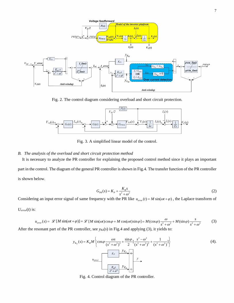
Fig. 1 shows the topology of the NPC three-phase three-level inverter with an LC filter at the output side. Fig. 2
shows the control scheme used in this paper. Conventionally, the anti-windup loops are added in the voltage and current
PR controllers to avoid the windup possibility of the resonate controller. However, based on this kind of control, it is
not enough to have a great performance of overload and short circuit protection. In the proposed control scheme, in
order to have a fast and accurate current limit under overload or short circuit conditions, if the output current exceeds
the limited value, the resonant part of the PR controller in current control loop will be reset to zero. Additionally,
compared with the conventional voltage and current control loops, the filter capacitor voltage Vc is feedforward to the

6
output of the current control loop. With the coordination of the three parts in the control scheme, which are the anti-
windup loops in the voltage and current controllers, the capacitor voltage feedforward control and the reset of the
resonant part of the current controller when overcurrent happens, a fast and accurate current limit performance can be
obtained. By the feedforward of the capacitor voltage, when overcurrent happens, especially under short circuit
condition, one can suppress the influence of the capacitor voltage to the output current. The reset of the resonator of
the current controller can reduce the modulation waveform quickly to the limited value to avoid the inverter going into
uncontrollable condition or the overshoot of the current. Each of the three parts plays an important role for the current
limit under overload or short circuit condition.
Fig. 1. Topology of the NPC inverter.
Fig. 3 shows the simplified linear control model for the voltage inverter in the UPS. In which, GV(s) represents the
transfer function of the voltage controller; GI(s) represents the transfer function of the current controller, and GPWM(s)
represents the transfer function of the inverter. Defining that:
2 2( ) RV
V PV
K sG s K
s = +
+,
2 2( ) RI
I PI
K sG s K
s = +
+,
1( )
1 1.5PWM PWM
s
G s KT
=+
(1)
where KPV and KRV are the proportional and resonate coefficients of the voltage PR controller, respectively; KPI and KRI
are the proportional and resonate coefficients of the current PR controller, respectively; and for the three-level voltage
source inverter, the gain KPWM equals to Vdc/2. Moreover, in order to suppress the influence of the fluctuation of the
DC bus voltage, the DC bus voltage will always be considered in the control, the PWM signal will be divided by Vdc/2
before sending to the driver circuit. So that the gain of the path from the output of the current controller to the inverter
output, from the point PWM* to the point VXO(s) (X=A, B, C) in Fig.2, will be one. Accordingly, a unit feedforward
control is applied in this paper, F(s)=1.
7
Fig. 2. The control diagram considering overload and short circuit protection.
Fig. 3. A simplified linear model of the control.
B. The analysis of the overload and short circuit protection method
It is necessary to analyze the PR controller for explaining the proposed control method since it plays an important
part in the control. The diagram of the general PR controller is shown in Fig.4. The transfer function of the PR controller
is shown below.
2 2( ) R
PR P
K sG s K
s = +
+ (2)
Considering an input error signal of same frequency with the PR like ( ) sin( )erroru t M t = + , the Laplace transform of
Uerror(t) is:
( )erroru s = ℒ [ sin( )]M t + = ℒ 2 2 2 2
[ sin( )cos cos( )sin ] (cos ) (sin )s
M t M t M Ms s
+ = +
+ + (3)
After the resonant part of the PR controller, see yKR(s) in Fig.4 and applying (3), it yields to:
2 2
2 2 2 2 2 2 2 2
sin 1( ) cos [ ]
( ) 2 ( ) ( )RK R
s sy s K M
s s s
−= + +
+ + + (4).
Fig. 4. Control diagram of the PR controller.

8
By using reverse Laplace transform of (4), it gives as following:
2 2 2 2 2 2
0
cos sin 1( ) [ (cos ) (sin ) ] sin( ) [ cos( ) sin( )]
2 2R
RK R
K ssy t M M K M t t t t t
s s s
= + = + +
+ + + (5).
Take two different values of as examples to analyze the output of resonant controller. When 0 = o , the output
signal would be:
cos sin 1( ) sin( ) [ cos( ) sin( )] sin( )
2 2 2R
RK R
K My t K M t t t t t t t
= + + =
(6)
when 90 = o , the output signal would be:
cos sin 1 1( ) sin( ) [ cos( ) sin( )] [ cos( ) sin( )]
2 2 2R
RK R
K My t K M t t t t t t t t
= + + = +
(7)
It can be noticed that the output increases with time until the input signal is zero, when adopted in a control
architecture, the final value of the resonant controller will be a constant with a zero steady state error if the controller
is well tuned. The resonant controller operates when an error signal is present. In addition, it can be noticed that the
resonant controller only work with a non-zero input signal. It means that the output of the resonant controller will
continue accumulate with the error signal over time. Therefore, a small error can become a large correction if given
enough time. As the error is accumulated, the system will be forced to correct the error until the steady state error is
zero. However, overshoot on the controlled signal always happens with an integral or resonant controller. To evaluate
the effectiveness of a controller in a control diagram, some tools can be applied.
Step response is often implemented to verify the effectiveness and stability of a control scheme [44]-[49]. Fast
dynamic response is necessary for a power system, and it can reduce the deviation of output voltage or current during
the transient event with effective control [44]. The unit step response is widely implemented in the power electrical
system, it is the time behavior of the output of the system when the input changes from 0 p.u. to 1 p.u. in a short time
but within the rated power of a system [50].
From a practical standpoint, knowing how the system responds to a sudden input is important because large and
possibly fast deviations from the long-term steady state may have extreme effects on the controller and on other
portions of the overall system dependent on this controller. In addition, the overall system cannot act until the
controller's output settles down to some vicinity of its final state, delaying the overall system response. Formally,
knowing the step response of a dynamical system gives information on the stability of such a system, and on its ability
to reach one stationary state when starting from another operation point [50].
Normally, three useful information we can get from the step response of a system: overshoot value, settling time and

9
status at steady state. When overload or short-circuit happens, the system will go into a new operation point, from the
load side point of view, it is like a serious load step change, more current need to be provided from the converter side.
To protect the hardware, we need to focus on these three aspects as well: to lower the overshoot, to decrease the settling
time from overshoot to steady state, to have an accurate current limit value at steady state. Thus, from step response
analysis of the control strategy, it guides us a way to improve the control.
Three different control configurations are considered to analyze the behavior of the step response of the control
architecture:
Case1: using only proportional controller KPI in the current control loop with the VC feedforward control, the close loop
transfer function of the current control loop is:
1( )
( ) ( ) ( )1
1 ( )
IPI
L ref ref
PII
G sKLs rLI s I s I s
Ls rL KG s
Ls rL
+= =+ +
++
(8).
Case 2: using PR controller in the current control loop without the VC feedforward control, the close loop transfer
function of the current control loop is:
2 2 2 2
3 2 2 2 3 2 2 2
1 1( )
( ) ( ) ( )1 1
1 ( ) 1 ( )
( ) ( )( ) ( ) ( ) ( ) ( ) ( )
I
L ref C
I I
PI RI PI oref C
PI o RI PI o PI o RI PI o
G sLs rL Ls rLI s I s V s
G s G sLs rL Ls rL
K s K s K sI s V s
Ls K rL s L K s K rL Ls K rL s L K s K rL
+ += −
+ ++ +
+ + += −
+ + + + + + + + + + + +
(9)
where ( ) ( )
( ) L oC
I s I sV s
Cs
−= , accordingly, one can obtain:
3 2 2
4 3 2 2 2 2
2 2
4 3 2 2 2 2
( ) ( )[( ) 1]
( )( ) [( ) 1] ( )
PI RI PI oL ref
PI o RI PI o o
oo
PI o RI PI o o
K Cs K Cs K CsI s I s
LCs K Cs L K C s K Cs
sI s
LCs K rL Cs L K C s K rL Cs
+ +=
+ + + + + +
++
+ + + + + + + +
(10).
In (9), it is clearly showing that, without VC feedforward control, the influence of the capacitor voltage to the inductor
current cannot be eliminated. In (10), the term Io(s) can be seen as an external interrupt.
Case 3: in order to decoupling the capacitor voltage VC(s) and the inductor current IL(s), VC feedforward control is
added into the current control loop, then the close loop transfer function of the current control loop will be:
2 2
3 2 2 2
1( )
( ) ( ) ( )1 ( ) ( ) ( )
1 ( )
IPI RI PI o
L ref ref
PI o RI PI oI
G sK s K s KLs rLI s I s I s
Ls K rL s L K s K rLG s
Ls rL
+ ++= =+ + + + + +
++
(11).

10
In (11), it can be noticed that the influence from the capacitor voltage to the inductor current is eliminated.
The unit step response analysis using Matlab for the abovementioned three cases, the result is shown in Fig.5 using
the parameters shown in Table I. It can be noticed that without the VC feedforward control in case 2, there is a big
overshoot at the very beginning, and the waveform oscillated with time at steady state. It could be foreseen that without
VC feedforward control, when serious overload or short circuit happens, there would be a giant overshoot in the output
current, and it will oscillate at steady state. However, with VC feedforward in case 3, the performance of both overshoot
suppression and settling time can be improved. In addition, one important discovery is that if VC feedforward is applied
with only P controller as shown in Case 1, there is no overshoot in the output, which makes clear that the behavior of
the resonant controller causes the overshoot.
Thus from Case 1, a very positive hint to additional improve the performance of overcurrent protection, resetting the
output of the resonator of current controller to zero when overcurrent happens, which can prevent the current going
into uncontrollable state.
TABLE I
Parameters of the controllers and hardware circuits in the experiments
Coefficient Parameters Value
Fundamental frequency ωo 314 rad/s
Filter capacitor Cf 60µF
Filter inductor Lf 200µH
Equivalent series resistance (ESR) of filter inductor rL 0.06Ω
Proportional part of the voltage controller KPV 0.8 A/V
Resonant part of the voltage controller KRV 1000 As/V
Proportional part of the current controller KPI 1.25 V/A
Resonant part of the current controller KRI 600 Vs/A
Preset current amplitude limit value Ilimit 20A
Nominal output voltage Vref 230Vrms
Switching frequency fs 20kHz
Digital signal processer (DSP) -- TMS320F28377D

11
zoomed-in
Fig. 5. Step response of different control configurations.
The overshoot is caused by the rapid accumulation of error. This large error is accumulated by the general integrator.
This is called “integral wind-up”. So anti-windup loop is often adopted with the PI or PR controller to suppress the
influence of the windup. Assume that an error exists, the resonator will accumulate this error over time. Therefore, the
output of the accumulator slowly rises. The overshoot is exacerbated by high resonant gain. Unfortunately, the effect
is also observed with low gains. The system may or may not settle at the set point. The operation of the resonator may
be improved by disabling the accumulation action if the output voltage is above a particular point. Therefore, a fast
reset the output of the resonant controller is essential when overload or short circuit happens.
As a conclusion of the proposed control scheme for a fast overload and short circuit protection, it mainly contains
three parts: the anti-windup loop in the PR controller, the output voltage feedforward control, and the fast reset of
resonant controller of current control loop. Each part plays an important role for a quick dynamic response when
overload or short circuit happens.
Compares to the methods in [40]-[43], when applying the method in this paper, the healthy phase will not be
influenced by the fault phase, and the phase angle of both voltage and current will not be changed, only the current
amplitude is limited to a preset value. In addition, the proposed method in this paper is capable for both overload, phase
to ground short circuit and phase to phase short circuit faults, while it only discussed one of them in other papers.

12
Among the algorithm based methods, the methods that proposed in [41] can provide overload protection, and phase
to ground short circuit protection but without phase to phase short circuit protection, which is used to compare with
the method in this paper. A table is provided in [41] to show the performance of the two methods, which is extended
to compare with the presented method in this paper that is shown in Table II. From the table, it can be noticed that even
the healthy phase will be influenced when fault happens, and the current limited value is not accurate, it varies under
different cases. Simulation and experimental results that provided in [41] show the phenomenon as well. When
applying the method in this paper, the healthy phase will not be influenced by the fault phase. In addition, the phase
angle of both voltage and current will not be changed, only the current amplitude is limited to a preset value, which is
fixed and accurate. It is only depend on different preset values for different rated power of UPS systems. The healthy
phase will not be influence by the fault phase as well when asymmetric overload or phase to phase short circuit happens,
which is not shown in the table. In addition, the method in this paper is valid for the three kinds of over current fault,
while the methods in [41] are only valid for two of them.
Table II Comparison with the methods in [41]
Items Methods Method I in [41] Method II in [41] Method in this paper
Output
current
Healthy phase zero pre-fault current pre-fault current, will
not be influenced by
fault phase
Fault phase The current limiting references
with reverse phase angle and
required current limiting
magnitude, varies current limit
value under different cases, 3
Ilimit, 2Ilimit or between the range
[Ilimit, 3 Ilimit]
The current limiting
references with regulated
phase angle and required
current limiting magnitude,
varies current limit value
under different cases, 3
Ilimit, 2Ilimit or between the
range [Ilimit, 3 Ilimit]
Limited amplitude
without changing the
phase angle. Limited to
the preset value
according to the
customers’
application.
Output
voltage
Healthy phase zero 86.6% of rated voltage
(phase angle changed as
shown in [41]
Rated voltage without
changing the phase
angle
Fault phase zero zero zero
Valid for fault types Overload, phase to ground
short cirvuit
Overload, phase to ground
short cirvuit
Overload, phase to
ground short circuit,
phase to phase short
circuit
III. EXPERIMENTAL RESULTS
In order to verify the effectiveness of the proposed overload and short circuit protection method for three phase
voltage source inverters, experiments have been developed by the real UPS system in Salicru S.A. Three cases of FUL

13
that cause overcurrent conditions mentioned in the introduction were considered: i) overload, ii) phase to ground short
circuit, and iii) phase to phase short circuit. The configuration of the control and platform is shown in Table I. Fig. 6
shows the NPC three-phase three-level inverter based UPS platform. Parameters of the filters and controllers are shown
in Table I.
Fig. 6. The prototype of the NPC three-phase three-level topology based UPS platform.
Fig. 7 shows the waveform of normal working condition. Sinusoidal waveform of output voltage is obtained, which
is the basic requirement of a UPS system. Fig. 8 shows the waveform when overload happens. It can be seen that when
a strong load, which is beyond the limit, was suddenly connected to the inverter, the output current will be limited to
the preset constant value. Under unknown overload condition, the output current is still controllable to avoid damage
of the load and the UPS itself. The other phenomenon that should be mentioned is that the UPS system will not be shut
down when overload happens, it is necessary for some of critical loads, such as telecommunication systems, network servers,
database system, and medical equipment.
Fig. 9 and Fig. 10 depict the waveforms when the UPS transfer from normal working condition to overload condition.
It is clearly showing the reset operation of the resonant regulator of the current controller in the DSP when overload
happens, which shows the same phenomenon of the simulation results. In addition, it shows an accurate current limit
performance since the current is limited to the preset value of 20A. The waveform looks good during the transient time

14
that demonstrate a good performance of the presented current limit control scheme.
Fig. 11 and Fig. 12 give the experimental results when phase to ground short circuit fault happens. It shows the
dynamic performance of the cases from normal to short circuit and the reverse. The output current can be limited to
the preset value quickly and went back to normal operation when the fault was cleared as expected.
Fig. 13 shows the results when the UPS operated under normal working condition with three-phase load. Fig. 14 and
Fig. 15 depict the waveforms when symmetric overload happens in three phases. It is a serious case from no load to
overload condition directly; however the current can still be limited to the preset value quickly and accurately by using
the proposed method. It shows the effectiveness of the presented control method. It should be noticed that the results
of Phase C was not shown in the experimental results since there are no more channels on one oscilloscope. Fig. 16 to
Fig. 18 are the experimental results when phase to phase short circuit fault happens. It can be noticed that the fault
happened on the two phases will not influence the normal operation of the other healthy phase, and it can go back to
normal operation quickly when the fault was cleared, very similar results are obtained as shown in the simulation. The
consistency of the simulation and experimental results further shows the effectiveness and the availability of the
proposed method.
Fig. 7. Normal operation with single-phase load, CH1: Output voltage; CH4: Output current.

15
Fig. 8. Overload happens with single-phase load, CH1: Output voltage; CH4: Output current.
Fig. 9. Single phase from normal to overload condition, CH1: Output voltage; CH2: Resonant output of current
controller in DSP; CH3: Inductor current; CH4: Output current.

16
Fig. 10. Overload happens with single-phase load, CH1: Output voltage; CH2: Resonant output of current controller
in DSP; CH3: Inductor current; CH4: Output current.
Fig. 11. Single phase from normal to phase to ground short circuit, CH1: Output voltage; CH4: Output current.

17
Fig. 12. Phase to ground short circuit condition switch to normal working condition on single-phase, CH1: Output
voltage; CH4: Output current.
Fig. 13. Three-phase load normal working condition, CH1: Phase A output voltage; CH2: Phase A output current;
CH3: Phase B output current; CH4: Phase C output current.

18
Fig. 14. Overload happens with three-phase load, CH1: Phase A output voltage; CH2: Phase B output voltage; CH3:
Phase A output current; CH4: Phase B output current.
Fig. 15. Three-phase overload switch to no load condition, CH1: Phase A output voltage; CH2: Phase B output
voltage; CH3: Phase A output current; CH4: Phase B output current.

19
Fig. 16. Normal operation to phase to phase short circuit, CH1: Phase A output voltage; CH2: Phase A output
current; CH3: Phase B output current; CH4: Phase C output current.
Fig. 17. Phase to phase short circuit to normal operation, CH1: Phase A output voltage; CH2: Phase A output current;
CH3: Phase B output current; CH4: Phase C output current.

20
Fig. 18. Normal operation to phase to phase short circuit, CH1: Phase A output voltage; CH2: Phase B output
voltage; CH3: Phase A output current; CH4: Phase B output current.
Finally, current limit tests when UPS inverters operate in parallel have been developed. Two different current limit
values have been selected to verify the effectiveness. Fig. 19(a) shows the results when the current limit value is 24A,
Fig. 19(b) depicts the results when the current is limited to 100A when stronger load is connected. From the results,
we can notice that an accurate current limit performance can be obtained even when inverters operate in parallel.

21
(a)
(b)
Fig. 19. Current limit results when UPS inverters operate in parallel, CH1: Phase A voltage of inverter 1; CH2: Phase
A voltage of inverter 2; CH3: Phase A current of inverter 1; CH4: Phase A current of inverter 2. (a) 24A current
limit, (b) 100A current limit.
IV. CONCLUSION
This paper presents a control method to ensure overload and short circuit protection in voltage source inverters based

22
UPS systems. With the proposed control method, UPS output current can be limited to a reference value within the
safe operation area, so that when overload or short circuit happens instantaneous voltage drop occurs. The proposed
solution compared with the state-of-the-art ones is superior in terms of accuracy and validity under more kinds of
overcurrent issues, while being compatible with advanced current/voltage tracker regulators based on resonant
controllers. Furthermore, as a sharp contrast with the existing techniques, the proposed approach is not only robust to
symmetric three-phase faults but also the asymmetric single-phase overload/short-circuit conditions in a three-phase
system, and the healthy phase will not be disturbed by the fault phase. Another brilliant feature is that as opposite to
conventional techniques in which the control has to switch between voltage to current mode once overload/short-circuit
occurs, and back to voltage mode once the fault is cleared, is that the proposed controller does not have to switch
between operation modes, which may lead to instabilities or oscillatory transients. In this approach, once the fault is
cleared, the UPS system can go quickly back to normal operation conditions without changing the control mode,
operating all the time as a voltage controlled source. Experimental results on a commercial UPS platform have been
implemented to verify the effectiveness of the proposed control method.
ACKNOWLEDGMENT
This project was cooperated between the Aalborg University and a UPS manufacture company named Salicru S/A
in Barcelona, Spain. Thanks to the colleagues, Jordi Montero, Santi Trujillo, Ramon Ciurans, Daniel Revilla, and
Andreu Sabe, in Salicru for their help on this project.
REFERENCES
[1] I. Lizama, R. Alvarez, S. Bernet, and M. Wagner, “A New Method for Fast Short Circuit Protection of IGBTs,” in
Proc. IEEE IECON 2014, Oct. 29–Nov. 1, pp. 1072–1076.
[2] B. Lu, S. K. Sharma, “A Literature Review of IGBT Fault Diagnostic and Protection Methods for Power Inverters,”
IEEE Trans. Ind. Appl., vol. 45, no. 5, pp. 1770–1777, Jul. 2009.
[3] T. Horiguchi, S.Kinouchi, Y. Nakayama, and H.Akagi, “A Fast Short-Circuit Protection Method Using Gate
Charge Characteristics of SiC MOSFETs,” in Proc. IEEE ECCE 2015, Sep. 20–24, pp. 4759–4764.
[4] M.Oinonen, M. Laitinen, and J. Kyyrä, “Current measurement and short-circuit protection of an IGBT based on
module parasitics,” in Proc. IEEE EPE 2014, Aug. 26–28, pp. 1–9.

23
[5] A. K. Irodi; N. R. Srinivas, “Active overcurrent protection schemes in bridge inverters operating under shoot-
through conditions,” in Proc. IEEE PICC 2015, Dec. 9–11, pp. 1–5.
[6] D. Sadik, J. Colmenares, D. Peftitsis, G. Tolstoy, J. Rabkowski, and H. Nee, “Analysis of Short-Circuit Conditions
for Silicon Carbide Power Transistors and Suggestions for Protection,” in Proc. IEEE EPE-ECCE Europe 2014,
Aug. 26–28, pp. 1–10.
[7] Y.Wang, C. Lee, P. Kuo, and Y. Lin, “Overcurrent Protection Design, Failure Mode and Effect Analysis of an
Electric Vehicle Inverter,” in Proc. IEEE ICIT 2016, Mar. 14–17, pp. 1287–1292.
[8] X. Pei and Y. Kang, “Short-circuit fault protection strategy for high-power three-phase three-wire inverter,” IEEE
Trans. Ind. Inform., vol. 8, no. 3, pp. 545–553, Aug. 2012.
[9] F. B. Costa, A. Monti and S. C. Paiva, “Overcurrent Protection in Distribution Systems With Distributed
Generation Based on the Real-Time Boundary Wavelet Transform,” IEEE Trans. Power Del., vol. 32, no. 1, pp.
462-473, Feb. 2017.
[10] J. H. Choi, K. J. Hong, J. S. Park, B. G. Gu, and C. Y. Won, “A New Short Circuit Protection Scheme for Small
Inverters,” in Proc. IEEE VPPC 2012, Oct. 9–12, pp. 1544–1547.
[11] X. Zhang, M. Chen, N. Zhu, and D. Xu, “A Self-Adaptive Blanking Circuit for IGBT Short-Circuit Protection
Based on VCE Measurement,” in Proc. IEEE ECCE 2015, Sep. 20–24, pp. 4125–4131.
[12] T. Horiguchi, S. Kinouchi, H. Urushibata, S. Okamoto, S. Tominaga, and H. Akagi, “A Short Circuit Protection
Method Based on a Gate Charge Characteristic,” in Proc. IEEE ECCE-Asia 2014, May. 18–21, pp. 2290–2296.
[13] M. E. Santos, B. J. C. Filho, “Short Circuit and Overcurrent Protection of IGCT-Based Three-Level NPC Inverters,”
in Proc. IEEE PESC 2004, Jun. 20–25, pp. 2553–2558.
[14] N. Bottrell, and T. C. Green, “Comparison of Current-Limiting Strategies During Fault Ride-Through of Inverters
to Prevent Latch-Up and Wind-Up,” IEEE Trans. Power Electron., vol. 29, no. 7, pp. 3786–3797, Jul. 2014.
[15] M. Oinonen, “Short Circuit Protection for a Power Transistor,” Master of Science Thesis, Aalto University,
Finland, 2013, pp. 81.
[16] A. Volke, M. Hornkamp, “IGBT Modules, Technologies, Driver and Application,” Infineon Technologies AG,
2011.

24
[17] W. El-Khattam and T. S. Sidhu, “Restoration of directional overcurrent relay coordination in distributed generation
systems utilizing fault current limiter,” IEEE Trans. Power Del., vol. 23, no. 2, pp. 576–585, Apr. 2008.
[18] W. El-Khattam and T. S. Sidhu, “Resolving the impact of distributed renewable generation on directional
overcurrent relay coordination: A case study,” IET Renew. Power Gen., vol. 3, no. 4, pp. 415–425, Dec. 2009.
[19] A. S. Noghabi, H. R. Mashhadi, and J. Sadeh, “Optimal coordination of directional overcurrent relays considering
different network topologies using interval linear programming,” IEEE Trans. Power Del., vol. 25, no. 3, pp. 1348–
1354, Jul. 2010.
[20] R. M. Chabanloo, H. A. Abyaneh, A. Agheli, and H. Rastegar, “Overcurrent relays coordination considering
transient behaviour of fault current limiter and distributed generation in distribution power network,” IET Gen.
Transm. Distrib., vol. 5, no. 9, pp. 903–911, Sep. 2011.
[21] M. J. Newman, and D. G. Holmes, “An Integrated Approach for the Protection of Series Injection Inverters,” IEEE
Trans. Ind. Appl., vol. 38, no. 3, pp. 679–687, May/Jun. 2002.
[22] R. S. Chokhawala, J. Catt, and L. Kiraly, “A Discussion on IGBT ShortCircuit Behavior and Fault Protection
Schemes,” IEEE Trans. Ind. Appl., vol. 31, no. 2, pp. 256–263, Mar./Apr. 1995.
[23] M. A. Rodr´ıguez-Blanco, A. Claudio-Sanchez, D. Theilliol, L. G. Vela-Valdes, P. Sibaja-Ter an, L. Hern
andez-Gonz alez, and J. Aguayo-Alquicira, “A Failure-Detection Strategy for IGBT Based on GateVoltage
Behavior Applied to a Motor Drive System,” IEEE Trans. Industry Electron., vol. 58, no. 5, pp. 1625–1633, May
2011.
[24] B. G. Park, J. B. Lee, and D. S Hyun, “A Novel Short-Circuit Detecting Scheme Using Turn-on Switching
Characteristics of IGBT,” in Conf. Rec. IEEE IAS Annual Meeting, 2008.
[25] S. Musumeci, R. Pagano, A. Raciti, G. Belverde, and M. Melito, “A New Gate Circuit Performing Fault
Protections of IGBTs During Short Circuit Transients,” in Conf. Rec. IEEE IAS Annual Meeting, 2002, vol. 3, pp.
2614–2621.
[26] K. Yuasa, S. Nakamichi, and I. Omura, “Ultra High Speed Short Circuit Protection for IGBT With Gate Charge
Sensing,” in Conf. Rec. IEEE ISPSD, 2010, pp. 37–40.
[27] T. Tanimura, K. Yuasa, and I. Omura, “Full Digital Short Circuit Protection for Advanced IGBTs,” in Conf. Rec.
IEEE ISPSD, 2011, pp. 60–63.
25
[28] K. Hasegawa, K. Yamamoto, H. Yoshida, K. Hamada, M. Tsukuda, and I. Omura, “Short-circuit protection for an
IGBT with detecting the gate voltage and gate charge,” Microelectron. Rel., vol. 54, pp. 1897–1900, 2014.
[29] K. Ishikawa, K. Suda, M. Sasaki, and H. Miyazaki, “A 600 V Driver IC with New Short Circuit Protection in
Hybrid Electric Vehicle IGBT Inverter System,” in Conf. Rec. IEEE ISPSD, 2005, pp. 59–62.
[30] B. G. Park, J. B. Lee, and D. S. Hyun, “A Novel Short-Circuit Detecting Scheme Using Turn-On Switching
Characteristic of IGBT,” In Industry Applications Society Annual Meeting, 2008. IEEE IAS, pp. 1 5.
[31] K. Yuasa, S. Nakamichi, and I. Omura, “Ultra High Speed Short Circuit Protection for IGBT With Gate Charge
Sensing,” In 22nd International Symposium on Power Semiconductor Devices IC's”, (ISPSD), June 2010, pp. 37-
40.
[32] A. Radun, “An alternative low-cost current-sensing scheme for high-current power electronics circuits,” IEEE
Trans. Ind. Electron., vol.42, no.1, pp.78-84, Feb 1995.
[33] F. Huang, F. Flett, “IGBT Fault Protection Based on di/dt Feedback Control,” In Power Electronics Specialists
Conference, IEEE PESC 2007, pp. 1478-1484.
[34] Zhiqiang Wang, Xiaojie Shi, L. M. T, “A Fast Overcurrent Protection Scheme for IGBT Modules Trough Dynamic
Fault Current Evaluation,” IEEE APEC, 2013, pp. 577-583.
[35] Z. Hu, C. Mao, J. Lu, and S. Fan, “Fuse protection of IGCTs against rupture in three-level commutated inverter,”
in Proc. IEEE ICPSC 2002, Oct. 13–17, pp. 611–615.
[36] D. Liu, A. Hu, G. Wang, and J. Guo, “Triple-Loop-Controlled Overload or Short Circuit Current Limiter and
Protection for Three Phase Inverter,” in Proc. IEEE ASEMD 2009, Sep. 25–27, pp. 201–205.
[37] Z. Chen , X. Pei , M. Yang , L. Peng , and P. Shi, “A Novel Protection Scheme for Inverter-Interfaced Microgrid
(IIM) Operated in Islanded Mode,” IEEE Trans. Power Electron., vol. 33, no. 9, pp. 7684-7697, Sep. 2018.
[38] M. J. Newman, and D. G. Holmes, “An Integrated Approach for the Protection of Series Injection Inverters,” IEEE
Trans. Ind. Appl., vol. 38, no. 3, pp. 679–687, May/Jun. 2002.
[39] R. Guzman, L. G. Vicuna, J. Morales, M. Castilla, and J. Miret, “Model-based Active Damping Control for Three-
Phase Voltage Source Inverters with LCL Filter,” IEEE Trans. Power Electron., IEEE Early Access Articles, DOI:
10.1109/TPEL.2016.2605858. Sep. 2016.

26
[40] M.S. Moon, R.W. Johnson, “DSP control of UPS inverter with over-current limit using droop method,” in Proc.
IEEE 30th Annual IEEE Power Electronics Specialists Conference, 1999, Jul., pp. 552–557, Charleston, SC, USA.
[41] Z. Liang , X. Lin , Y. Kang, B. Gao, and H. Lei, “Short Circuit Current Characteristics Analysis and Improved
Current Limiting Strategy for Three-phase Three-leg Inverter under Asymmetric Short Circuit Fault,” IEEE Trans.
Power Electron., vol. 33, no. 8, pp. 7214-7228, Aug. 2018.
[42] H. Wang, X. Pei, Y. Chen, Y. Kang, and Y. F. Liu, “Short-circuit fault protection strategy of parallel three-phase
inverters,” in Proc. IEEE Energy Convers. Congr. Expo., Montreal, QC, 2015, pp. 1736–1742.
[43] P. Nuutinen, P. Peltoniemi, and P. Silventoinen, “Short-circuit protection in a converter-fed low-voltage
distribution network,” IEEE Trans. Power Electron., vol. 28, no. 4, pp. 1587–1597, Apr. 2013.
[44] D. Segaran, D. G. Holmes and B. P. McGrath, “Enhanced Load Step Response for a Bidirectional DC–DC
Converter,” IEEE Trans. Power Electron., vol. 28, no. 1, pp. 371-379, Jan. 2013.
[45] C. A. Reis and N. A. P. Silva, “Sufficients Conditions for Analysis of Extrema in the Step-response of the Linear
Control Systems,” in IEEE Latin America Transactions, vol. 9, no. 7, pp. 1025-1031, Dec. 2011.
[46] F. Zhang and Y. Yan, “Start-Up Process and Step Response of a DC–DC Converter Loaded by Constant Power
Loads,” in IEEE Trans. Ind. Electron, vol. 58, no. 1, pp. 298-304, Jan. 2011.
[47] J. Kim, J. Lee, S. Cho, C. Hwang, C. Yoon and J. Fan, “Analytical Probability Density Calculation for Step Pulse
Response of a Single-Ended Buffer With Arbitrary Power-Supply Voltage Fluctuations,” in IEEE Transactions on
Circuits and Systems I: Regular Papers, vol. 61, no. 7, pp. 2022-2033, July 2014.
[48] T. J. Freeborn, B. Maundy and A. S. Elwakil, “Measurement of Supercapacitor Fractional-Order Model
Parameters From Voltage-Excited Step Response,” in IEEE Journal on Emerging and Selected Topics in Circuits
and Systems, vol. 3, no. 3, pp. 367-376, Sept. 2013.
[49] H. Oka, Y. Baba, M. Ishii, N. Nagaoka and A. Ametani, “Parametric Study on Unit Step Responses of Impulse
Voltage Measuring Systems Based on FDTD Simulations,” in IEEE Trans. Power Del., vol. 28, no. 1, pp. 376-
382, Jan. 2013.
[50] C. Benjamin Kuo, F. Golnaraghi, “Automatic control systems,” (2003, Eighth ed.). New York: Wiley.
p. 253. ISBN 0-471-13476-7.