aade-14-ftce-3 acidizing high temperature carbonate ... · microcapsules as an additive for...
TRANSCRIPT

Copyright 2014, AADE
This paper was prepared for presentation at the 2014 AADE Fluids Technical Conference and Exhibition held at the Hilton Houston North Hotel, Houston, Texas, April 15-16, 2014. This conference was sponsored by the American Association of Drilling Engineers. The information presented in this paper does not reflect any position, claim or endorsement made or implied by the American Association of
Drilling Engineers, their officers or members. Questions concerning the content of this paper should be directed to the individual(s) listed as author(s) of this work.
Abstract
Hydrochloric acid (HCl) is the most commonly used
stimulation fluid for high-temperature wells drilled in carbonate
reservoirs. However, the high reaction rate of HCl with
carbonate rocks and high corrosion rate on well tubulars make
its use in deep wells non-viable. The current study introduces
the novel application of methanesulfonic acid (MSA), a strong
organic acid, to increase the permeability of carbonate
formations. Demonstration of the effectiveness of MSA in
generating wormholes in carbonate cores will offer the
petroleum industry with an alternative system to HCl for
stimulating high-temperature carbonate formations.
Coreflood studies were conducted at 250°F using limestone
cores and a 10 wt%-MSA aqueous solution. A constant
injection rate was maintained, and the differential pressure
through the core was measured until acid breakthrough.
Collected samples of the effluent fluids were analyzed using
inductively coupled plasma (ICP), and a computed tomography
(CT) scan of each core was performed after the acid injection.
MSA was found effective in creating wormholes in
limestone cores at a temperature of 250°F. At low injection
rates, face dissolution and conical channels were observed in
the cores. At intermediate injection rates, no face dissolution
appeared and the tendency was to create a few dominant
wormholes. At high injection rates, several ramified wormhole
structures were found. For the conditions tested, an optimum
flow rate was identified. This paper summarizes the results
obtained and the recommendations for the use of MSA in
carbonate acidizing applications.
Introduction
Hydrochloric acid (HCl) is generally selected for carbonate
acidizing because it reacts readily with carbonate minerals
producing soluble reaction products, and it is available in large
quantities at a relatively low price. The main disadvantage of
HCl is its high corrosivity on wellbore tubular goods, especially
at temperatures above 250°F (Williams et al. 1979). Another
limitation of the use of HCl is its negative environmental
impact. HCl is toxic to aquatic life by lowering the pH and is
not expected to biodegrade when it is released into the soil.
There are numerous problems associated with the high
corrosion rate of HCl at high temperatures. First, well tubulars
are often made of low-carbon steel, but in certain applications
the well completion may include aluminum- or chromium-
plated components (i.e., 13% chromium tubulars suitable for
applications involving CO2 rich environments) that become
easily damaged upon contact with HCl solutions (Nasr-El-Din
et al. 2003). In addition, HCl will dissolve any rust present in
the tubulars and produce a great quantities of iron (Fe+3), which
will precipitate as Fe(OH)3 (Crowe 1985; Taylor et al. 1999) or,
if H2S is present, as iron sulfide (Nasr-El-Din et al. 2002),
potentially causing formation damage.
Various additives, such as corrosion inhibitors and inhibitor
aids, are used to reduce corrosion by HCl at high temperatures.
The cost of these additives, however, may result in the
treatment being uneconomical (Fredd 1997). Also, the use of
corrosion inhibitors in high concentrations may result in
undesired wettability changes of the formation as the inhibitor
may adsorb on the rock surface (Schechter 1992). These
drawbacks make organic acids attractive for stimulating high-
temperature wells.
Organic acids are typically used as an alternative to HCl in
high-temperature formations (Chatelain et al. 1976; Van
Domelen and Jennings 1995; Fredd and Fogler 1998a; Huang
et al. 2000; Nasr-El-Din et al. 2001; Al-Katheeri et al. 2002;
Buijse et al. 2004; Alkhaldi et al. 2009; Nasr-El-Din et al.
2013). These acids are less corrosive and spend slower in
carbonate rock than HCl, thus providing deeper penetration and
improved stimulation. Therefore, they are preferred when the
treating temperature prevents efficient protection against
corrosion and/or when the treatments are limited to low
injection rates to avoid fracturing the formation. In contrast to
these advantages, Chang et al. (2008) listed some limitations
associated with the use of weak organic acids: they cannot be
used at high acid concentration, they have a low dissociation
constant, their degree of hydrogen ion generation decreases
with an increase in temperature, and their cost is significantly
higher than that of HCl for an equivalent mass of rock
dissolved.
Some methods, including the use of sulfonic acids, have
been tried in an effort to overcome the drawbacks for both
mineral and conventional organic acid systems used in
carbonate stimulation. Sulfonic acids, which have the formula
RSO3H, are described as a group of organic acids that contain
one or more sulfonic, –SO3H, groups (Tully 2000). Although
the R-group may be derived from many different sources,
AADE-14-FTCE-3
Acidizing High Temperature Carbonate Reservoirs Using Methanesulfonic Acid: A Coreflood Study Alexis Ortega and Hisham A. Nasr-El-Din, Texas A&M University; Shawn Rimassa, BASF Corporation

2 A. Ortega, H.A. Nasr-El-Din and S. Rimassa AADE-14-FTCE-3
typical R-groups are alkane, alkene, alkyne, and arene. Sulfonic
acids are such strong acids (as strong as sulfuric acid) that they
dissociate completely in water (King 1991). The obtained pKa
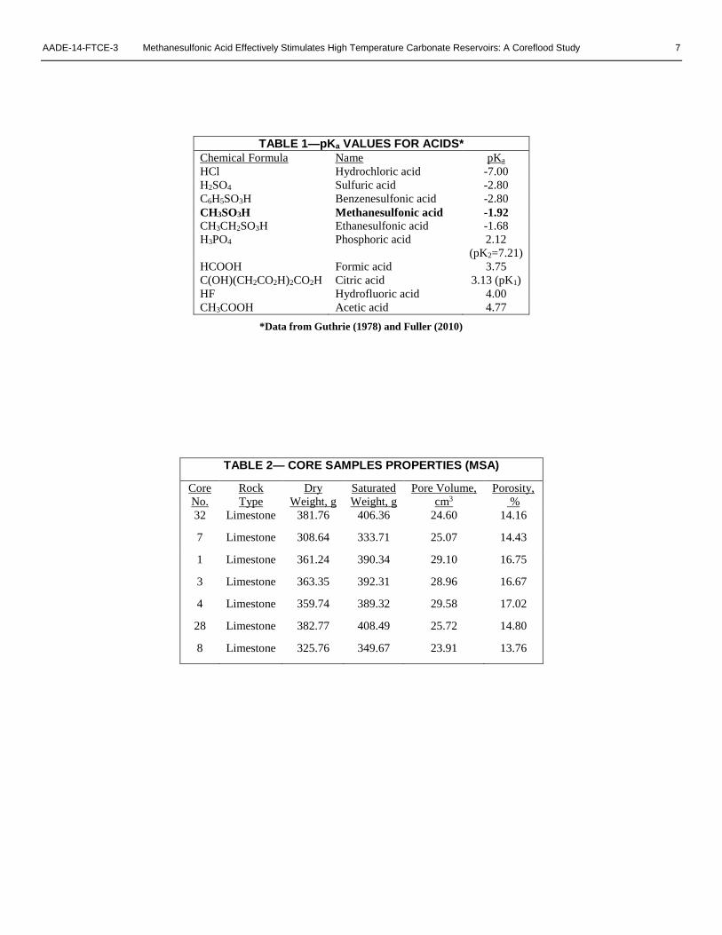
value for MSA is -1.92 (Covington and Thompson 1974). As
seen in Table 1, sulfonic acids are stronger than conventional
organic acids but not as strong as HCl. Because of their unique
chemical and physical properties, sulfonic acids have found
wide application in the chemical and pharmaceutical industries,
and more recently in the oilfield.
One of the first references of the potential use of
alkanesulfonic acids for the treatment of oilfield wells is found
in a patent filed by Tate (1982), who disclosed a method for
improving the recovery of hydrocarbons in sandstone
formations. More recently, Fu (2010) proposed the injection of
an aqueous mixture for the treatment of sandstone formations,
which consisted of a surfactant, an inorganic acid (for example
HCl), and an organic acid (such as formic acid, acetic acid,
citric acid, or MSA). In a similar application, Fuller (2010)
presented a method for treating sandstone formations which
consisted of injecting a blend of an aqueous liquid, a fluoride
source, and an effective amount of an alkane sulfonic acid,
preferably MSA. The stimulation of carbonate formations using
alkanesulfonic acids, and in particular MSA, was first disclosed
by Heidenfelder et al. (2009). In a more recent publication,
Bertkau and Steidl (2012) disclosed an innovative method
comprising the use of alkanesulfonic acid (MSA)
microcapsules as an additive for carbonate acidizing
applications. None of the previous studies found in literature
included a description of the wormholing characteristics of
sulfonic acids (and specifically, MSA) when they are injected
through carbonate cores at high temperature conditions.
A coreflood study was conducted to determine the
effectiveness of MSA in creating wormholes during the
stimulation or carbonate reservoirs. MSA was found able to
generate wormholes when it was injected through limestone
cores at 250°F. From the study, an optimum acid injection rate
was identified, and the effect of the generated dissolution
patterns on acid efficiency was analyzed.
Background on Optimum Injection Rate
Wormholes are deep, highly ramified dissolution channels
formed by the reaction of acid with porous carbonate rocks. The
control of the formation of these channels, which are an order
of magnitude larger in diameter than the naturally occurring
pores, is important for the success of stimulation treatments
(Hill and Schechter 2000). When evaluating the performance of
a newly proposed acid system or comparing its properties to
commonly used acids, the characterization of these dissolution
patterns is required.
In order to understand the wormholing process, many
theoretical models have been developed (Buijse and Glasbergen
2005; Daccord et al. 1989; Economides et al. 2013; Furui et al.
2012a, 2012b; Hoefner and Fogler 1988; Hung et al. 1989;
Pichler et al. 1992). One of the main challenges of these models
is the determination of the dissolution pattern as a function of
acid injection rate. Daccord et al. (1989), for example, defined
three domains of dissolution patterns as functions of flow rate:
compact (stable) dissolution at low flow rates, wormhole
(unstable) domain at intermediate flow rates, and uniform
dissolution (homogeneous etching) at high flow rates.
In addition to the theoretical models, numerous laboratory
studies have shown a dependency of the efficiency of acidizing
treatments on the generated dissolution pattern. This
observation has resulted in the concept of an “optimum
injection rate” (Fredd and Fogler 1998a; Hoefner and Fogler
1989; Wang et al. 1993).
The optimum flow rate is defined as the acid injection rate
corresponding to the minimum volume of acid required for
wormhole breakthrough. This optimum rate has been found to
be determined by the dissolution pattern created by the acid
reaction, and therefore is a function of rock composition, acid
concentration, reaction temperature, core length, and formation
permeability (Bazin 2001; Fredd and Fogler 1999; Wang et al.
1993).
Identifying the optimum injection rate for a given rock/acid
system is critical for the comprehension of the wormholing
mechanisms. This is a base parameter for the design (selection
of acid concentration, acid volume, and injection rate) of acid
treatments. Therefore, it is necessary to determine the optimum
injection rate for the new stimulation fluid (MSA) in carbonate
rocks.
Experimental Procedures
Laboratory coreflood experiments were conducted with
Indiana limestone core samples and 10 wt% MSA. The
experiments were performed at a temperature of 250°F. An
overburden pressure of 1,800 psi was applied to the core cell by
means of a manual hydraulic pump connected to the coreflood
setup. A new core was used for each experiment.
The acid was injected into the core at a constant flow rate
until breakthrough was observed. A minimum pressure of 1,100
psi was maintained in the core by a backpressure regulator
downstream of the core. This pressure was required to prevent
a separate CO2-rich phase from forming.
During acid injection, samples of the effluent were collected
and analyzed for pH, calcium concentration, and post-treatment
acid concentration. An Orion PrepHecT Ross Electrode was
used to measure the pH value of the samples. The calcium
concentration and final acid concentration in the core effluent
samples were determined by using the inductively coupled
plasma (ICP) and the Titrando 907 equipment, respectively.
Finally, after the acid injection, computed tomography (CT)
scans of the core samples were performed to characterize the
generated wormholes.
Materials
The acid solutions were prepared using commercially
available Baso® MSA (70 wt% MSA) and corrosion inhibitor
BASF-JJ-103, both of which were provided by BASF. The
water used throughout the experiments was deionized water
with a resistivity of 18.2 MΩ•cm at room temperature.

AADE-14-FTCE-3 Methanesulfonic Acid Effectively Stimulates High Temperature Carbonate Reservoirs: A Coreflood Study 3
Acid Preparation
The MSA was obtained at an initial concentration of 70
wt%. For the experimental procedure, the acid was diluted to a
concentration of 10 wt% (MSA10) using deionized water.
Corrosion inhibitor at a concentration of 2 vol% was added to
the diluted acid solution.
Core Preparation
Core samples, from a block of Indiana limestone, were cut
into cylinders of 1.5-in. diameter and 6-in. length. The samples
were dried in an oven at a temperature of 250°F for 8 hours and
then weighed. After this, the samples were saturated in water
under vacuum conditions for 24 hours and weighed. From the
difference in weight of the dry and saturated core samples, the
average porosity was calculated and found to be in the range of
13.7 to 17.0%.
Before the acid injection, the core samples were placed
inside the core holder, and deionized water was injected at
different flow rates (5, 10, and 20 cm3/min). The pressure drop
across the cores at each flow rate was recorded, and Darcy’s
law was used to determine the initial (absolute) permeability of
the cores. Table 2 summarizes the properties of the cores used.
Coreflood Setup
The coreflood setup (Fig. 2) was used to test the
performance of the new organic acid system. A pressure
transducer was connected to a computer with LabView®*
software installed to monitor and record the pressure drop
across the core during the experiments. A Teledyne ISCO D-
series D1000 precision syringe pump with a maximum
allowable working pressure of 2,000 psi was used to inject the
acid into the core.
To heat the core to the required test temperature, a heat
jacket was placed around the core holder.The temperature was
controlled by a compact bench top CSC32 series with a 4-digit
display and a 0.1° resolution with an accuracy of ±0.25% full
scale ±1°C. It uses a type-K thermocouple and two outputs (5
A 120 Vac SSR). Water was injected at 2 cm3/min during the
heating period.
Experimental Procedures
Seven coreflood runs were performed using 10 wt% MSA,
at injection rates from 1 to 20 cm3/min. These runs were done
to test the effect of the injection rate on MSA performance,
specifically, the acid volume to breakthrough, and the resulting
wormhole characteristics. All the experiments were executed at
a temperature of 250°F. Table 3 presents a summary of the
results obtained for each of the core samples used. During
coreflood injection, the pressure drop across the core was
plotted using the LabView® software. Samples of the coreflood
effluent were collected and analyzed for calcium concentration,
pH, and final acid concentration (acid titration).
*A registered trademark of National Instruments
The analyses performed for Core 1 (5 cm3/min) are provided
as an example of the complete coreflood procedure. Fig. 3
shows the behavior of the pressure drop across the core during
the injection of the 10 wt% MSA system at a rate of 5 cm3/min.
The differential pressure, which initially stabilized at 7.5 psi
during the injection of water, started to decrease shortly after
the acid injection began. This decrease in pressure indicates the
reaction of the acid with the carbonate rock, and the creation of
dissolution patterns (wormholes) as the acid front was moving
along the core length. The differential pressure continued to
decrease with time until acid breakthrough occurred.
The volume of acid to breakthrough is defined as the volume
of acid needed to propagate the wormhole through the length of
the core. When breakthrough was achieved, a low and constant
(stable) pressure drop was recorded from the coreflood
apparatus, indicating that the fluid was flowing through the
created wormhole structures. For the current case, 3.27 pore
volumes (PV) of acid were needed to achieve breakthrough
(Fig. 3) when 10 wt% MSA was injected at 5 cm3/min through
a limestone core at 250°F.
As MSA reacted with the carbonate rock creating
dissolution channels along the core, the calcium concentration
in the effluent samples started to increase. Fig. 4 shows the
calcium concentration in the effluent samples, as measured by
the ICP equipment, corresponding to the coreflood experiment
described in Fig. 2. It shows that the total measured calcium
concentration reached a maximum value of 21,595 mg/l ± 4%.
This value is in agreement with the maximum theoretical value
that can be calculated for a 10 wt% MSA solution (21,700
mg/l).
Fig. 5 shows the pH and final acid concentration of the
coreflood effluent samples for the same experiment. The pH
was around 7 at the start of the injection (water). Then it
decreased with the injection of acid to a value of 1.0 (after acid
breakthrough) and increased again as the injection of water
restarted. As expected, an opposite trend was found for the final
acid concentration on the effluent samples, which achieved a
maximum value of 1.15 wt% MSA after acid breakthrough.
This indicated that the acid was almost completely spent after
its flow through the carbonate core.
To observe the effect of the acid on the inlet and outlet sides
of the core and to identify dissolution structures created by the
acid reaction with the limestone rock, photographs of the core
sample were taken before and after the acid injection (Fig. 6).
This figure shows that, for intermediate injection rates (5
cm3/min), several pores for wormhole initiation were present,
without dissolution of the inlet face of the core. Since this rate
is close to the optimum, a few dominant wormholes of
intermediate size were created.
A procedure similar to the one explained above for Core 1
was followed for all the other core samples used in the study
(Table 2). Fig. 7 shows the behavior of the pressure drop across
the core during the injection of the 10 wt% MSA system at
injection rates of 1.5, 10, and 20 cm3/min. As described above,
in each case the differential pressure decreased with time as
wormholes were created until acid breakthrough was achieved.
4 A. Ortega, H.A. Nasr-El-Din and S. Rimassa AADE-14-FTCE-3
Fig. 8 presents the ICP measured calcium concentrations in
the coreflood effluent samples, collected for some of the
experiments at different injection rates. As in the case of Core
1, the calcium concentration increased with the injection of
acid, reaching a maximum value, then decreased when the
injection fluid was switched back to water.
The calcium concentration is related to the amount of
carbonate rock dissolved by acid, and this amount is greater for
greater acid/rock contact times/area. Consequently, the highest
peak for calcium concentration was noticed at injection rates of
1 and 20 cm3/min (the least optimal cases, highest contact
time/area), while the lowest peak was observed at injection
rates of 7.5 cm3/min (the most optimal case, lowest contact
time).
Similarly, the change in pH can be compared for all the
cases tested (Fig. 9). The decrease in pH to a minimum value
indicates acid breakthrough, therefore it can be used to confirm
the breakthrough determined from the analysis of the pressure
drop. This minimum value of pH varied in the range of 0.97
(Core 8, 20 cm3/min) to 1.87 (Core 32, 1 cm3/min). The results
in Fig. 9 also demonstrate the dependency of pH on injection
rate. The higher the acid injection rate, the lower the time the
acid has for spending upon contact with the carbonate rock,
therefore resulting in lower pH of the effluent samples.
Optimum Injection Rate
The optimum injection rate is the rate at which the volume
of acid required to achieve breakthrough is minimum. The
volume of acid to breakthrough as a function of interstitial
velocity is shown in Fig. 10. From this figure, as the injection
rate increases, the volume of acid to breakthrough decreases
and reaches a minimum at a rate between 5 and 7.5 cm3/min
(2.6 to 3.9 cm/min). At injection rates higher than the optimum,
the volume of acid to achieve breakthrough increases again.
However, the curve is steeper on the left side of the optimum
injection rate and relatively flat for rates higher than the
optimum. This fact indicates that the effect of the injection rate
is more pronounced at low injection rates, corresponding to a
mass-transfer-limited regime. On the other hand, a surface-
reaction-limited regime is reached for high injection rates, with
the pore volumes to breakthrough being affected less by
changes in injection rate.
A figure similar to Fig. 10 can be constructed by plotting, as
a function of interstitial velocity, the photographs of the inlet
side of the core samples after acid injection (Fig. 11). This is
done to observe the dissolution patterns obtained at each flow
rate, which will govern the shape of the optimum injection rate
curve. As mentioned before, the optimum injection rate is
determined by the dissolution patterns created by the acid
reaction.
As seen in Fig. 11, at low injection rates (1 cm3/min), some
degree of face dissolution, as well as conical wormholes, is
present in the core sample making the acidizing process
(wormhole penetration) significantly inefficient. As the
injection rate is increased for intermediate flow rates (from 5 to
10 cm3/min), almost no face dissolution appears on the core
sample, and the tendency is to create a few dominant
wormholes.
The lowest volume of acid to breakthrough is obtained when
acid is injected at 7.5 cm3/min, and therefore, for the conditions
tested, this is considered the optimum injection rate when 10
wt% MSA is injected through limestone cores at a temperature
of 250°F. Finally, for high injection rates (above 10 cm3/min),
several dominant wormholes were created with increased
wormhole branching as flow rate increased.
CT Scan Images
The dissolution structures that were created at the different
flow rates considered in the coreflood study can be
characterized by analyzing the 2D scan images of the cores
treated with 10 wt% MSA. Fig. 12 (top) presents the CT scan
images for a low-injection case (Core 2, 2 cm3/min), showing
the wormholing ability of MSA at this injection rate.
Dissolution of the inlet face of the core can be observed in the
initial images (dark spots in the images as a result of a low CT
number). A conical wormhole is also visible, which caused the
core stimulation to be inefficient (sub-optimal).
Fig. 12 (bottom), on the other hand, shows the 2D scan
images for a case close to the optimum rate (Core 3, 7.5
cm3/min), on which no face dissolution of the core was
observed; additionally, a single dominant wormhole was
created, penetrating the total length of the core. The size of the
generated wormhole decreased as the acid penetrated deeply
into the core, until acid breakthrough was achieved. This
dissolution pattern resulted in an efficient stimulation of the
core.
Analysis of the 2D scan images provides an explanation for
the difference in calcium concentration measured for both the
low injection rate case and the near-optimum rate case,
described in a previous section. At a low injection rate (2
cm3/min), a large volume of MSA is consumed on the inlet flow
face of the core (face dissolution). Also at this rate, the reactant
penetrates into the porous matrix and enlarges flow channels.
However, a significant amount of MSA is consumed on the
walls of these flow channels, causing the formation of a conical-
shaped dissolution channel. This conical channel requires the
injection of several pore volumes of acid for the channel to
break through the porous medium. The combined effect of face
dissolution and conical channels results in a high degree of acid
reaction with the rock, which in turn generates a high amount
of calcium ions in the effluent samples.
On the other hand, at an intermediate injection rate (7.5
cm3/min) unconsumed MSA reaches the tip of the growing flow
channels. Successive consumption at the tip extends the
dissolution channels and leads to the development of a
dominant wormhole of reduced size. This dominant wormhole
requires a minimum pore volume of acid to break through the
rock matrix. For that reason, the calcium concentration of the
effluent samples at this intermediate rate is lower than the
corresponding concentration for the low injection rate case.
From the study of the 2D scan images it is confirmed that
MSA can be used as an effective stimulation fluid at
intermediate flow rates, being able to create deep, dominant

AADE-14-FTCE-3 Methanesulfonic Acid Effectively Stimulates High Temperature Carbonate Reservoirs: A Coreflood Study 5
wormholes without face dissolution. The generation of a
dominant wormhole provides a significant increase in
permeability, as shown in Fig. 13, which describes the
permeability enhancement obtained in carbonate cores tested
with MSA at different injection rates, after acid breakthrough
occurred.
During coreflood testing, the pressure drop across the rock
is measured as dissolution progresses, and the average
permeability of the rock is calculated using Darcy’s law. It can
be observed from results in Fig. 13 that the amount of acid
required to increase the average permeability by a certain factor
depends on the acid injection rate. For example, at a very low
injection rate (i.e., 1 cm3/min), the average permeability
increases slowly with the pore volumes of acid injected. As the
acid injection rate is increased, the rate of increase in average
permeability increases up to a certain acid injection rate (7.5
cm3/min). At this acid-injection rate, the optimum injection
rate, permeability increment is steepest as compared with other
acid-injection rates. For acid-injection rates (i.e., 20 cm3/min)
higher than the optimum acid-injection rate, the rate of
permeability increment decreases with the increase in the
injection rate.
Conclusions
MSA is a suitable alternative stimulation fluid for carbonate
acidizing at high temperatures (250°F). A 10 wt% MSA
aqueous acid solution was used to stimulate limestone cores
using a coreflood setup. Based on the results obtained, the
following conclusions can be drawn:
1. MSA was found to be effective in creating
wormholes in limestone cores at different injection
rates and at a temperature of 250°F. At low injection
rates (lower than 1.5 cm3/min), face dissolution and
conical channels were observed in the cores. At
intermediate injection rates (5 to 10 cm3/min),
almost no face dissolution appears on the core
samples, and the tendency is to create a few dominant
wormholes. At high injection rates (above 10
cm3/min), several dominant wormhole structures
were found with increased branching for increased
flow rates.
2. For the acid injection rates covered in the current
study, an optimum injection rate between 5.0 and 7.5
cm3/min was determined when MSA (10 wt%) was
used to stimulate limestone cores at 250°F.
3. From ICP analysis of the effluent samples, a
maximum calcium ion concentration of about 22,000
mg/l was determined. This is in agreement with the
maximum calcium theoretical dissolution for 10 wt%
MSA.
Acknowledgments
The authors would like to acknowledge BASF for granting
permission to publish and present this paper. The authors also
thank Kristina Hansen for proofreading this paper.
References 1. Al-Katheeri, M.I., Nasr-El-Din, H.A., Taylor, K.C. et al. 2002.
Determination and Fate of Formic Acid in High Temperature
Acid Stimulation Fluids. Presented at the International
Symposium and Exhibition on Formation Damage Control, held
in Lafayette, Louisiana, 20-21 February 2002. SPE-73749-MS.
2. Alkhaldi, M.H., Nasr-El-Din, H.A., and Sarma, H.K. 2009.
Application of Citric Acid in Acid Stimulation Treatments.
Presented at the Canadian International Petroleum Conference,
held in Calgary, Alberta, 16 - 18 June 2009. PETSOC-2009-015.
4. Bazin, B. 2001. From Matrix Acidizing to Acid Fracturing: A
Laboratory Evaluation of Acid/Rock Interactions. SPE
Production & Operations 16 (1): 22-29. SPE-66566-PA.
5. Bertkau, W. and Steidl, N. 2012. Alkanesulfonic Acid
Microcapsules and Use Thereof in Deep Wells, US
2012/0222863 A1, Sep. 6, 2012. United States: BASF SE.
6. Buijse, M., Boer, P.d., Breukel, B. et al. 2004. Organic Acids in
Carbonate Acidizing. SPE Production & Operations 19 (3): 128-
134. SPE-82211-PA.
7. Buijse, M.A. and Glasbergen, G. 2005. A Semiempirical Model
to Calculate Wormhole Growth in Carbonate Acidizing.
Presented at the SPE Annual Technical Conference and
Exhibition, held in Dallas, Texas, 9-12 October 2005. SPE-
96892-MS.
8. Chang, F.F., Nasr-El-Din, H.A., Lindvig, T. et al. 2008. Matrix
Acidizing of Carbonate Reservoirs Using Organic Acids and
Mixture of Hcl and Organic Acids. Presented at the SPE Annual
Technical Conference and Exhibition, held in Denver, Colorado,
USA, 21-24 September 2008. SPE-116601-MS.
9. Chatelain, J.C., Silberberg, I.H., and Schechter, R.S. 1976.
Thermodynamic Limitations in Organic-Acid/Carbonate
Systems. Society of Petroleum Engineers Journal 16 (4): 189-
195. SPE-5647-PA.
10. Covington, A. and Thompson, R. 1974. Ionization of Moderately
Strong Acids in Aqueous Solution. Part Iii. Methane-, Ethane-,
and Propanesulfonic Acids at 25°C. Journal of Solution
Chemistry 3 (8): 603-617.
11. Crowe, C.W. 1985. Evaluation of Agents for Preventing
Precipitation of Ferric Hydroxide from Spent Treating Acid.
Journal of Petroleum Technology 37 (4): 691-695. 00012497.
12. Daccord, G., Touboul, E., and Lenormand, R. 1989. Carbonate
Acidizing: Toward a Quantitative Model of the Wormholing
Phenomenon. SPE Production Engineering 4 (1): 63-68. SPE-
16887-PA.
13. Economides, M.J., Hill, A.D., Ehlig-Economides, C. et al. 2013.
Carbonate Acidizing Design. In Petroleum Production Systems,
Second edition, Prentice Hall. 438-467.
15. Fredd, C.N. 1997. The Influence of Transport and Reaction of
Wormhole Formation in Carbonate Porous Media: A Study of
Alternative Stimulation Fluids. 9825217 Ph.D., University of
Michigan.
16. Fredd, C.N. and Fogler, H.S. 1998a. Alternative Stimulation
Fluids and Their Impact on Carbonate Acidizing. SPE Journal 3
(1): 34-41. SPE-31074-PA.
17. Fredd, C.N. and Fogler, H.S. 1998b. Influence of Transport and
Reaction on Wormhole Formation in Porous Media. American
Institute of Chemical Engineers.AIChE Journal 44 (9): 1933.
18. Fredd, C.N. and Fogler, H.S. 1999. Optimum Conditions for
Wormhole Formation in Carbonate Porous Media: Influence of
Transport and Reaction. SPE Journal 4 (3): 196-205. SPE-56995-
PA.
19. Fu, D. 2010. Self-Diverting Pre-Flush Acid for Sandstone, US
7,666,821 B2, Feb. 23, 2010. United States: Schlumberger

6 A. Ortega, H.A. Nasr-El-Din and S. Rimassa AADE-14-FTCE-3
Technology Corporation.
20. Fuller, M.J. 2010. Method for Treating a Subterranean
Formation, US 7,753,123 B2, Jul. 13, 2010. United States:
Schlumberger Technology Corporation.
21. Furui, K., Burton, R.C., Burkhead, D.W. et al. 2012a. A
Comprehensive Model of High-Rate Matrix-Acid Stimulation for
Long Horizontal Wells in Carbonate Reservoirs: Part I--Scaling
up Core-Level Acid Wormholing to Field Treatments. SPE
Journal 17 (1): pp. 271-279. SPE-134265-PA.
22. Furui, K., Burton, R.C., Burkhead, D.W. et al. 2012b. A
Comprehensive Model of High-Rate Matrix-Acid Stimulation for
Long Horizontal Wells in Carbonate Reservoirs: Part Ii--
Wellbore/Reservoir Coupled-Flow Modeling and Field
Application. SPE Journal 17 (1): pp. 280-291. SPE-155497-PA.
23. Guthrie, J.P. 1978. Hydrolysis of Esters of Oxy Acids: P K a
Values for Strong Acids; Brønsted Relationship for Attack of
Water at Methyl; Free Energies of Hydrolysis of Esters of Oxy
Acids; and a Linear Relationship between Free Energy of
Hydrolysis and P K a Holding over a Range of 20 P K Units.
Canadian Journal of Chemistry 56 (17): 2342-2354.
24. Heidenfelder, T., Guzmann, M., Witteler, H. et al. 2009. Methods
of Increasing Permeability in Carbonatic Rock Formations with
Alkanesulfonic Acids, US 7,638,469 B2, Dec. 29, 2009. United
States: BASF SE.
25. Hill, A.D. and Schechter, R.S. 2000. Fundamentals of Acid
Stimulation. In Reservoir Stimulation, Third edition eds.
Economides, M.J. and Nolte, K.G., Wiley Chichester. 1-28.
26. Hoefner, M. and Fogler, H.S. 1988. Pore Evolution and Channel
Formation During Flow and Reaction in Porous Media. AIChE
Journal 34 (1): 45-54.
27. Hoefner, M.L. and Fogler, H.S. 1989. Fluid-Velocity and
Reaction-Rate Effects During Carbonate Acidizing: Application
of Network Model. SPE Production Engineering 4 (1): 56-62.
SPE-15573-PA.
28. Huang, T., Ostensen, L., and Hill, A.D. 2000. Carbonate Matrix
Acidizing with Acetic Acid. Presented at the SPE International
Symposium on Formation Damage Control, held in Lafayette,
Louisiana, 23-24 February 2000. SPE-58715-MS.
29. Hung, K.M., Hill, A.D., and Sepehrnoori, K. 1989. A
Mechanistic Model of Wormhole Growth in Carbonate Matrix
Acidizing and Acid Fracturing. Journal of Petroleum Technology
41 (1): 59-66. SPE-16886-PA.
30. King, J.F. 1991. Acidity. In The Chemistry of Sulphonic Acids,
Esters, and Their Derivatives, First edition eds. Patai, S. and
Rappoport, Z., The Chemistry of Functional Groups, John Wiley
& Sons. 249-260.
31. Nasr-El-Din, H., Sayed, M., Aften, C. et al. 2013. A New Organic
Acid to Stimulate Deep Wells in Carbonate Reservoirs. Presented
at the 2013 SPE International Symposium on Oilfield Chemistry,
held in The Woodlands, TX, USA, 8 - 10 April 2013. SPE-
164110-MS.
32. Nasr-El-Din, H.A., Al-Humaidan, A.Y., Fadhel, B.A. et al. 2002.
Investigation of Sulfide Scavengers in Well-Acidizing Fluids.
SPE Production & Operations 17 (4): 229-235. SPE-80289-PA.
33. Nasr-El-Din, H.A., Driweesh, S.M., and Muntasheri, G.A. 2003.
Field Application of Hcl-Formic Acid System to Acid Fracture
Deep Gas Wells Completed with Super Cr-13 Tubing in Saudi
Arabia. Presented at the SPE International Improved Oil
Recovery Conference in Asia Pacific, held in Kuala Lumpur,
Malaysia, 20-21 October 2003. SPE-84925-MS.
34. Nasr-El-Din, H.A., Lynn, J.D., and Taylor, K.C. 2001. Lab
Testing and Field Application of a Large-Scale Acetic Acid-
Based Treatment in a Newly Developed Carbonate Reservoir.
Presented at the SPE International Symposium on Oilfield
Chemistry, held in Houston, Texas, 13-16 February 2001. SPE-
65036-MS.
35. Pichler, T., Frick, T.P., Economides, M.J. et al. 1992. Stochastic
Modeling of Wormhole Growth in Carbonate Acidizing with
Biased Randomness. Presented at the European Petroleum
Conference, held in Cannes, France, 16-18 November 1992.
SPE-25004-MS.
36. Schechter, R.S. 1992. Oil Well Stimulation. Prentice Hall.
37. Tate, J.F. 1982. Aqueous Acid Solution Containing an
Acrylamido Alkanesulfonic Acid Polymer, 4,332,688, Jun. 1,
1982. United States: Texaco Inc.
38. Taylor, K.C., Nasr-El-Din, H.A., and Al-Alawi, M.J. 1999.
Systematic Study of Iron Control Chemicals Used During Well
Stimulation. SPE Journal 4 (1): 19-24. 00054602.
39. Tully, P.S. 2000. Sulfonic Acids. In Kirk-Othmer Encyclopedia
of Chemical Technology, First edition, John Wiley & Sons, Inc.
1-22.
40. Van Domelen, M.S. and Jennings, J., A. R. 1995. Alternate Acid
Blends for Hpht Applications. Presented at the Offshore Europe,
held in Aberdeen, United Kingdom, 5-8 September 1995. SPE-
30419-MS.
41. Wang, Y., Hill, A.D., and Schechter, R.S. 1993. The Optimum
Injection Rate for Matrix Acidizing of Carbonate Formations.
Presented at the SPE Annual Technical Conference and
Exhibition, held in Houston, Texas, 3-6 October 1993. SPE-
26578-MS.
42. Williams, B.B., Gidley, J.L., and Schechter, R.S. 1979. Chapter
3. Acid Types and the Chemistry of Their Reactions. In Acidizing
Fundamentals, edition, SPE Monograph Series, Henry L.
Doherty Memorial Fund of AIME, Society of Petroleum
Engineers of AIME. 10-18.
AADE-14-FTCE-3 Methanesulfonic Acid Effectively Stimulates High Temperature Carbonate Reservoirs: A Coreflood Study 7
TABLE 1—pKa VALUES FOR ACIDS*
Chemical Formula Name pKa
HCl Hydrochloric acid -7.00
H2SO4 Sulfuric acid -2.80
C6H5SO3H Benzenesulfonic acid -2.80
CH3SO3H Methanesulfonic acid -1.92
CH3CH2SO3H Ethanesulfonic acid -1.68
H3PO4 Phosphoric acid 2.12
(pK2=7.21)
HCOOH Formic acid 3.75
C(OH)(CH2CO2H)2CO2H Citric acid 3.13 (pK1)
HF Hydrofluoric acid 4.00
CH3COOH Acetic acid 4.77
TABLE 2— CORE SAMPLES PROPERTIES (MSA)
Core
No.
Rock
Type
Dry
Weight, g
Saturated
Weight, g
Pore Volume,
cm3
Porosity,
%
32 Limestone 381.76 406.36 24.60 14.16
7 Limestone 308.64 333.71 25.07 14.43
1 Limestone 361.24 390.34 29.10 16.75
3 Limestone 363.35 392.31 28.96 16.67
4 Limestone 359.74 389.32 29.58 17.02
28 Limestone 382.77 408.49 25.72 14.80
8 Limestone 325.76 349.67 23.91 13.76
*Data from Guthrie (1978) and Fuller (2010)

8 A. Ortega, H.A. Nasr-El-Din and S. Rimassa AADE-14-FTCE-3
TABLE 3—SUMMARY OF COREFLOOD RESULTS (MSA)
Core
No.
Permeability,
md
Injection Rate,
cm3/min
Interstitial
Velocity, cm/min
Pore Vol. to
Breakthrough
32 172.3 1.0 0.6 9.18
7 172.1 1.5 0.9 4.56
1 120.6 5.0 2.6 3.27
3 95.7 7.5 3.9 3.00
4 83.4 10.0 5.2 4.25
28 257.4 15.0 8.9 5.44
8 220.8 20.0 12.7 6.48
Fig. 1–Structural formula of methanesulfonic acid (MSA).

AADE-14-FTCE-3 Methanesulfonic Acid Effectively Stimulates High Temperature Carbonate Reservoirs: A Coreflood Study 9
Fig. 2–Coreflood setup used to simulate matrix stimulation treatments.
Fig. 3–Pressure drop across Core 1 during the injection of the 10 wt% MSA
system at a rate of 5 cm3/min. Pressure decreased with time as wormholes were
created, until acid breakthrough occurred. 3.26 PV of acid were injected.

10 A. Ortega, H.A. Nasr-El-Din and S. Rimassa AADE-14-FTCE-3
Fig. 4–Calcium concentration in the effluent samples of Core 1 from ICP equipment. A maximum value of 21,595 mg/l ± 4%
was measured, which is in agreement with the theoretical value calculated for a 10 wt% MSA. Error bars represent relative
standard deviation (RSD) from the measurements.
Fig. 5–pH and final acid concentration in effluent samples of Core 1. After
acid breakthrough, pH reached a minimum value of 1.0, corresponding to a
final acid concentration of 1.1 wt% MSA.

AADE-14-FTCE-3 Methanesulfonic Acid Effectively Stimulates High Temperature Carbonate Reservoirs: A Coreflood Study 11
Inlet Outlet
Before Acid
After Acid
Fig. 6–Photographs of inlet/outlet of Core 1, taken before/after acid reaction.
For intermediate injection rates (5 cm3/min), a slight degree of face dissolution
was present with a few dominant wormholes of intermediate size.
Fig. 7–Pressure drop across different core samples during the injection of the 10 wt% MSA system at
injection rates of 1.5, 10, and 20 cm3/min. In all cases, pressure decreased with time as wormholes were
created, until acid breakthrough was achieved.

12 A. Ortega, H.A. Nasr-El-Din and S. Rimassa AADE-14-FTCE-3
Fig. 8–Calcium concentration in the coreflood effluent samples, collected for the various experiments with MSA at
different injection rates (± 4%, relative standard deviation). Highest peak for calcium concentration was found for the
highest contact time cases. The lowest peak was observed for the lowest contact time cases (intermediate rates), which
are closest to the optimum injection rate.
Fig. 9–pH of the coreflood effluent samples, collected for the various experiments with MSA at
different injection rates. Acid breakthrough is indicated by the decrease in the pH measurement.
pH measurement increases again after water injection is restarted.

AADE-14-FTCE-3 Methanesulfonic Acid Effectively Stimulates High Temperature Carbonate Reservoirs: A Coreflood Study 13
Fig. 10–Optimum injection rate curve for the reaction of MSA with limestone at 250°F. As the injection rate increased,
the volume of acid to breakthrough decreased and reached a minimum at a rate between 5 and 7.5 cm3/min (2.6 to 3.9
cm/min). At injection rates higher than the optimum, the volume of acid to breakthrough increased.
Fig. 11–Dissolution patterns after injection of 10 wt% MSA were identified from photographs of inlet side of
core samples. At low injection rates, face dissolution and conical wormholes are observed. Almost no face
dissolution occurs at intermediate flow rates, and single dominant wormholes are created. At high injection
rates, several dominant wormholes are created with increasing branching as flow rate is increased.

14 A. Ortega, H.A. Nasr-El-Din and S. Rimassa AADE-14-FTCE-3
CT Scan Core 2 - low-injection rate case (2 cm3/min)
CT Scan Core 3 - intermediate-injection rate case (7.5 cm3/min)
Fig. 12–Low injection (top) leads to face dissolution and conical wormholes.
Dominant wormholes are a characteristic of the intermediate rate case (bottom).
Fig. 13–Permeability enhancement by injection of 10 wt% MSA in carbonate cores. Figure shows the dependency of acid-
injection rate on the amount of acid required to increase the average rock permeability by a certain factor.