aabc commissioning group 2018 presentations/venn...test and balance issues—from precise...
TRANSCRIPT

AABC Commissioning GroupAIA Provider Number 50111116
Fundamentals of Test & Balance for
Engineers, Cx & Energy Providers
Course Number: CXENERGY1815
Brian Venn, TBE, CxAMechanical Testing, Inc.
April 25, 2018

Credit(s) earned on completion of this course will be reported to AIA CES for AIA members. Certificates of Completion for both AIA members and non-AIA members are available upon request.
This course is registered with AIA
CES for continuing professional
education. As such, it does not
include content that may be
deemed or construed to be an
approval or endorsement by the
AIA of any material of construction
or any method or manner of
handling, using, distributing, or dealing in any material or product._______________________________________
Questions related to specific materials, methods, and services will be addressed at the conclusion of this presentation.

SAMPLE OPTIONAL SLIDE
This presentation is protected by US and International Copyright laws. Reproduction, distribution, display and use of the
presentation without written permission of the speaker is prohibited.
(Company Logo is acceptable here)
© The name of your company 2012
Copyright Materials

This practical, information-packed session explains many of the key
test and balance issues—from precise specifications, to duct
leakage testing, to pump- and fan-curve considerations—that if
properly addressed in cooperation with an independent TAB firm
can ensure that any project goes smoothly.
CourseDescription

LearningObjectives
1. Understand the proper use, application, and limitations of the TAB instrumentation.
2. Understand what is accurate, useful and meaningful data that is obtained in the
field vs. laboratory data for use on their project.
3. Gain an understanding of HVAC systems and the TAB/measurement process; how
can systems be set up to allow for proper data collection.
4. Promote a project team approach to address schedule challenges, design
alternatives as it relates to balancing device locations, equipment usage and HVAC
system operation.
At the end of the this course, participants will be able to:

Sample Last Slide
This concludes The American Institute of Architects Continuing Education Systems
Course
Contact Information

Test & Balance Primerfor Engineers:
Recommendations for
Optimum System Performance

Recommendations Overview
Specification Issues
Fan Curves
Traverse Locations & Alternatives
System Effect
Pump Curves
Pump Flow Measurement
Equipment Considerations
Project Issues

Specification Issues
The specification document indicates that an AABC-certified TAB agency must perform the work.
Only AABC requires that its members be INDEPENDENT, with no other ties to the project.
List the TAB Agencies approved to bid the project.
The specification clearly defines the systems to be balanced. List a schedule of equipment that requires TAB work.

Specification Issues
The specification clearly defines the scope of work pertaining to the systems to be balanced:
Create a performance specification that relates to the project and data required.

Specification Issues
Try to think of how data will be obtained and what data will be required before specifying the requirements.
Will the requested data be accurate, repeatable and meaningful?
Avoid ±5% tolerances
For most projects, overly tight tolerances add to the cost, but not to system performance.
Reserve tight tolerances for special applications, not comfort cooling/heating.
The TAB Equipment manufacturer’s tolerances sometimes exceed the specification tolerances.

Specification Issues
Coordinate controls, sheet metal, and insulation specifications with TAB specification.
Insulation specification requires that:
All water test ports are accessible.
All balancing damper handles are exposed and visible on externally insulated ductwork.
Water flow measuring stations need complete access from insulation to verify sizes and models. The tags sent with the flow measuring stations may be used, but verification of the correct tag needs to be verified (on the valve body), especially automatic balancing valves.

Specification Issues
Control specification requires that:
Access to the control system is made available to the TAB agency and any required hardware/software is provided by the controls contractor at no additional expense to the owner or TAB agency.

Specification Issues
Sheave changes are NOT automatically the responsibility of the mechanical contractor or TAB agency.
It is difficult to define who is responsible --Manufacturer, contractor, engineer? How many are required? At bid time, sheaves are an unknown cost and unknown quantity.
Sheave changes for fans should be included as an allowance in the project or handled as a cost plus change order.
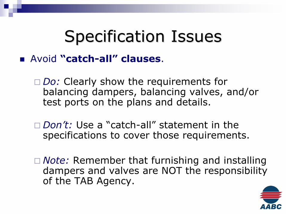
Specification Issues
Avoid “catch-all” clauses.
Do: Clearly show the requirements for balancing dampers, balancing valves, and/or test ports on the plans and details.
Don’t: Use a “catch-all” statement in the specifications to cover those requirements.
Note: Remember that furnishing and installing dampers and valves are NOT the responsibility of the TAB Agency.
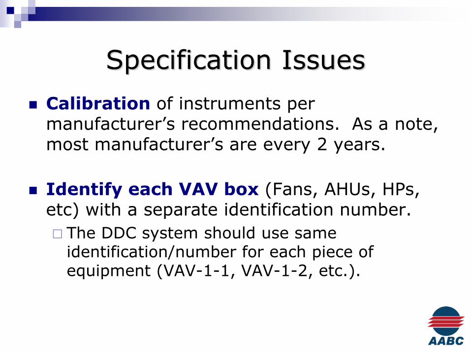
Specification Issues
Calibration of instruments per manufacturer’s recommendations. As a note, most manufacturer’s are every 2 years.
Identify each VAV box (Fans, AHUs, HPs, etc) with a separate identification number.
The DDC system should use same identification/number for each piece of equipment (VAV-1-1, VAV-1-2, etc.).

Specification Issues
Clarification on testing of domestic water, DI water systems, etc. is required.
Some TAB equipment manufacturers prohibit the use of their equipment on potable water systems due to potential contamination.
Consider installing temperature sensors on the domestic hot water recirculation loop that can report the temperatures to the DDC system.
Plumbing pumps or fire pumps: If these are systems that cannot maintain an established water flow, then the water flow cannot be measured.(See previous note.)

Specification Issues Duct leakage testing needs to be coordinated in
the specification.
Who does it?
How many tests are required?
What standard is it done to?
If required, be specific about what sound (& vibration?) data is required and where readings are to be taken.

Fan Curves
Fan curves AMCA Tested
Produced under laboratory conditions
Free inlet
Straight discharge
Ideal traverse plane
Multiple speeds-extrapolated data
Standard temperature & pressure (STP)
Normal manufacturing tolerances
Know the limitations of fan curves

Fan Curves
ASHRAE Journal Article, November 2005

Traverse Locations & Alternatives
Ideal traverse plane:
AABC, AMCA & ASHRAE all identify as 2 ½ diameters from condition (discharge, elbow, etc.) for up to 2500 fpm. Add 1 diameter for each additional 100 fpm.
Rectangular Duct EL= (4a*b/)0.5 , where “a” & “b” are the duct dimensions.

Traverse Locations & Alternatives
Example:
10,000 cfm, 30” x 20” duct, 2400 fpm
EL= (4a*b/∏)0.5 =27.6”2 ½ * 27.6” = 69.1”
69.1” (~ 6’) straight duct required
Alternatives to Traverse:
Face velocity reading of filters, coils, hood face, etc.
Summation of airflows at individual outlets
Summation of calibrated VAV boxes as read at the DDC computer
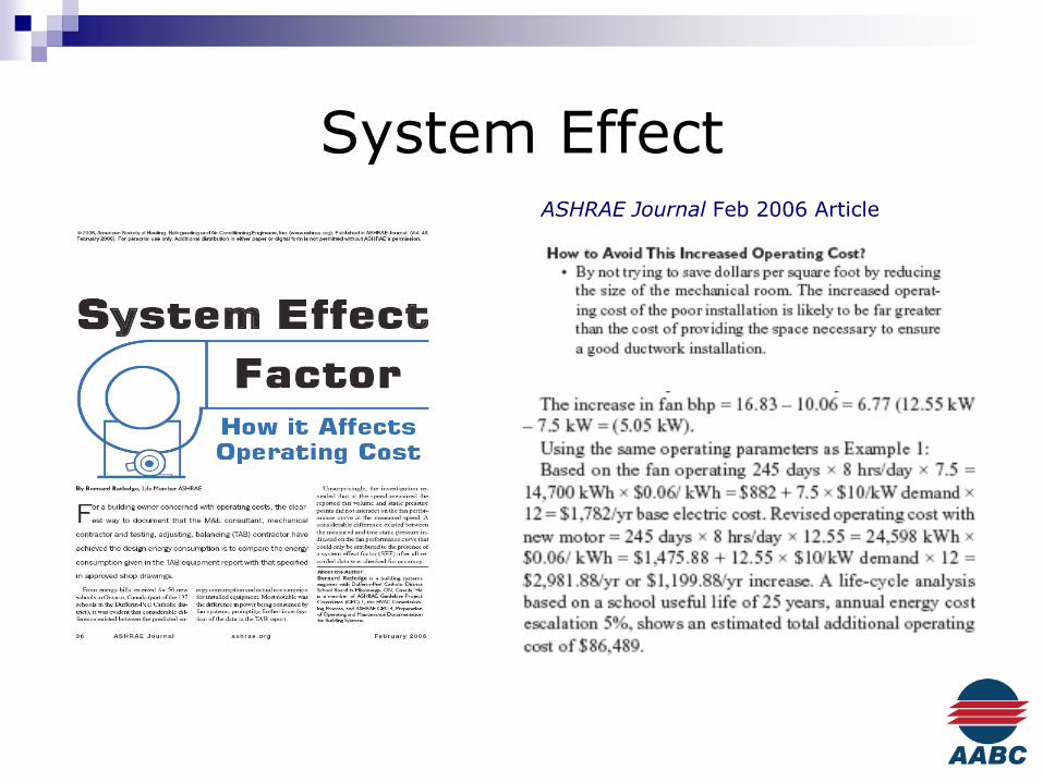
System EffectASHRAE Journal Feb 2006 Article

System Effect
TAB Journal article
Spring 2010

System Effect

System EffectStandard 17,500 CFM Packaged RTU

Pump CurvesDesign Requirements: 800 gpm @ 68’
9” Impeller, 20 hp motor, 5BC,1750 rpm (Point 1)
Field Measurements: Shutoff ΔP = 73’ (Point 2) Operating ΔP = 70.0’
Results: Actual: 700 gpm w/9” imp 12.5% below design Flat Pump Curve – Hard to
interpolate. Utilize measured flows at
terminals or branches to determine pump total.

Pump CurvesDesign Requirements: 800 gpm@ 68’
10-3/8” Impeller, 20 hp motor, 4E, 1750 rpm
Field Measurements: Shutoff ΔP = 104’ Operating ΔP = 72’
Results: Actual: 775 gpm w/10-
3/8” imp 3.1% below design Steep Pump Curve –
Immediate Resolution.

Pump Flow Measurement
Provide test ports/pump taps at the pumps (Extend outside of insulation).
Provide a flow measuring device at the pump
Fixed orifice type device preferred, not MPVs, etc.

Scheduling Challenges
There needs to be enough time allowed in the schedule for the TAB work to be completed.
All work must be complete for TAB work to commence.
Clean air filters installed.
All strainers must be cleaned and start-up strainers removed.
All balancing dampers installed and 100% open.
All manual water valves and flow measuring stations should be 100% open.
Controls are complete and functional.

Scheduling Challenges
Phased projects:
Remember that the TAB work is completed by HVAC system and NOT area.
Very seldom does the HVAC system match the “Phasing Areas.”
Make sure that the Owner & Architect understand the possibility that the TAB work might be performed after occupancy. (Bid appropriately.)
Variable volume systems (air and water) can have provisions to balance partial HVAC systems. For phased projects, constant volume systems are much more difficult to address.
Water systems (heating & chilled) need to be reviewed for TAB scheduling.

Access Challenges
Proper clearance and access must be provided to all dampers, valves, equipment, etc. This includes the test ports on flow measuring devices and auto-flows.
Sheet rock ceilings, Architectural features, etc.
Access to outlets, dampers, etc. in theatre type seating areas. How will this be accomplished? AHU is typically not in operation when scaffolding is installed.

Equipment ConsiderationsExamples of no access in Factory Package Automatic Balancing Valves

Why Specify AABC?
AABC is the only test & balance organization that adheres to these Guiding Principles:
Independence:AABC requires its members to be 100% Independent.
Guaranteed Performance:All work by AABC members is covered by the National Performance Guaranty
Quality Assurance:AABC solicits engineer feedback on every job
For more information see www.aabc.com, email [email protected] or call 202-737-0202.

Why Mechanical Testing, Inc.
Brian Venn – Vice President CxA/TBE
51 years in business
Mechtest.com for list of services
Independence from Mechanical Contractor
Proud Member of ACG, AABC and ASHRAE

Questions?
Thank you for your time!
Additional Presentation Topics:
Duct Leakage Testing
Balancing Hydronic Systems
Hot Water Reheat Balancing