aa 10s-1r switch set 10s-1r aa 32 33 - taiyo-ltd.co.jp · pdf file10s-1r switch set 10s-1r ......
TRANSCRIPT

Compact Design Pneumatic Cylinder/Switch Set10S-1R
10S-1R Space-saving Pneumatic Cylinder
32AA Compact Design Pneumatic Cylinder/
Switch Set 10S-1RSpace-saving P
neumatic C
ylinder 10S-1R
33AA
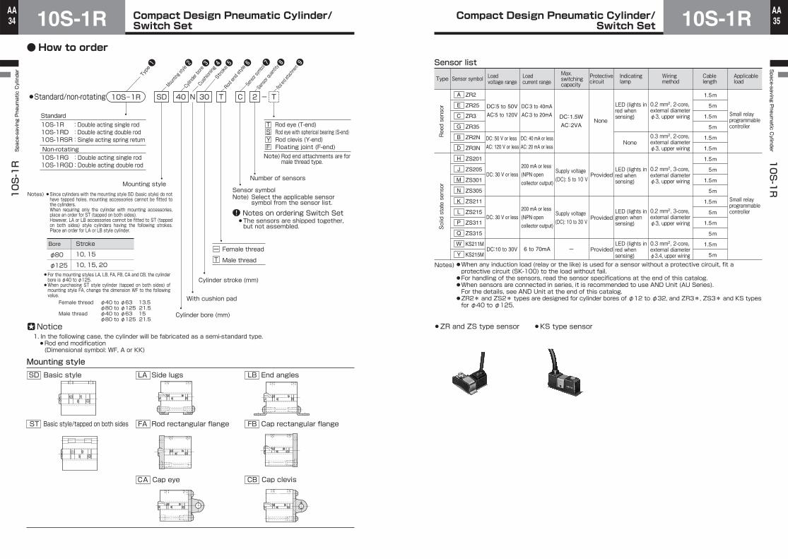
(Notes)●SD (basic) style cylinders are not tapped, and mounting accessories cannot be fitted to them. When requiring only the cylinder with mounting accessories, place an order for ST (tapped on both sides).
●Mounting accessories can be fitted to standard double acting type cylinders having bores of φ40 to φ125 and non-rotating double acting type cylinders having bores of φ40 to φ100. (Double rod cylinders of mounting styles FB, CA and CB are not available.) Single acting cylinders are available only with bores of φ40 and φ50.
●All rod end attachments are for male thread type. The rod eye and rod clevis with pin are applicable to φ12 to φ125, the rod eye with spherical bearing is applicable to φ20 to φ100, and the floating joint is applicable to φ20 to φ125.
●When the sensor is installed at the intermediate position, the cylinder max. speed must be less than 300 mm/s for reasons of the response speed of the load relay.
Compact, lightweight, space saving air cylinder with sensorSwitch Set Cylinders having piston with built-in magnet.Non-rotating types are available.Separable type convenient for maintenance.Female and male threaded rod ends areavailable.For φ12 to φ32, stainless steel (hard chrome plated) piston rods are used.
Cylinder specificationsSeries variations
Type
Cylinder bore (mm)
Cylinder bore (mm)
Working fluid
Lubrication
Working pressure range
Proof test pressure
Working temperature range
Structure of cushioning
Tolerance for thread
Tolerance of stroke
Note) Mounting style
Rod end threads
Air
Unnecessary (but possible)
Switch Set
1.5 MPa
Specifications / non-rotating rod
Double acting single rod Double acting double rod
Double acting single rod Double acting double rod
Single acting spring return type (SR type)
φ12・φ16・φ20・φ25・φ32・φ40φ50・φ63・φ80・φ100・φ125
φ12・φ16・φ20・φ25φ32・φ40・φ50
φ12・φ16:0.07 to 1 MPaφ20 to φ125:0.05 to 1 MPa
φ12・φ16:0.2 to 1 MPaφ20・φ25:0.18 to 1 MPaφ32 to φ50:0.12 to 1 MPa
-10 to +70℃ (no freezing)
JIS 6H/6g
Female thread and male thread
SD (basic style) or ST (tapped on both sides)LA・LB・FA・FB・CA・CB
SD (basic style) or ST (tapped on both sides)LA・LB・FA
SD (basic style) or ST (tapped on both sides)LA・LB・FA・FB・CA・CB
φ12 and φ16: None φ20 to φ125: With cushion pad φ12 and φ16: None φ20 to φ125: With cushioning pad on cap side
+1.0 mm 0
Series variations
Type
Working fluidLubricationWorking pressure range
Proof test pressureWorking temperature rangeStructure of cushioning
Tolerance for threadTolerance of strokeNote) Mounting styleRod end threads
Allowable rotating angle
Allowable torque
AirUnnecessary (but possible)
φ20・φ25・φ32・φ40・φ50・φ63・φ80・φ100
Female thread and male thread
SD (basic style) or ST (tapped on both sides)LA・LB・FA・FB・CA・CB
SD (basic style) or ST (tapped on both sides)LA・LB・FA
0.1 to 1 MPa 1.5 MPa
φ20・φ25: ±1.5° φ32 to φ63: ±1° φ80・φ100: ±0.8°
JIS 6H/6g +1.0 mm 0
-10 to +70℃ (no freezing)With cushion pad
φ20・φ25:0.49N・m φ32・φ40:0.98N・m φ50・φ63:3.33N・m φ80・φ100:9.61N・m
Switch Set
Single acting spring return type spring force Unit: N
5
9.8
14.7
18.6
23.5
33.3
43.1
-
-
10
7.8
10.8
15.7
19.6
28.4
38.2
56.9
15
8.8
12.7
17.7
24.5
35.3
48.1
65.7
20
7.8
11.8
16.7
22.6
33.3
46.1
63.7
25
-
-
-
-
15.7
20.6
31.4
44.1
60.8
30
-
-
-
-
14.7
19.6
29.4
43.1
58.8
73.5
35
-
-
-
-
-
-
-
-
-
-
41.2
58.8
40
-
-
-
-
-
-
-
-
-
-
40.2
53.9
45
-
-
-
-
-
-
-
-
-
-
38.2
51.0
50
-
-
-
-
-
-
-
-
-
-
37.3
49.0
11.8
28.4
39.2
48.1
14.7
21.6
17.7
29.4
41.2
53.0
φ12
φ16
φ20
φ25
φ32
φ40
φ50
Cylinder stroke (mm)
Double acting single rod10S-1R
Double acting double rod10S-1RD
Product lineupSeries Variations φ12 φ16 φ20 φ25 φ32 φ40 φ50 φ63 φ80 φ100 φ125
Unit: mm
Single acting spring return10S-1RSR
10S-1RG
10S-1RGDNon-rotating
Standard
Double acting single rod
Double acting double rod
LoadBore(mm)
Initial load
End load
Initial load
End load
Initial load
End load
Initial load
End load
Initial load
End load
Initial load
End load
Initial load
End load
Compact Design Pneumatic Cylinder/Switch Set10S-1R
10S-1R Space-saving Pneumatic Cylinder
34AA Compact Design Pneumatic Cylinder/
Switch Set 10S-1RSpace-saving P
neumatic C
ylinder 10S-1R
35AA
FA Rod rectangular flange FB Cap rectangular flange
SD Basic style LA Side lugs LB End angles
ST Basic style/tapped on both sides
BCC Cap eye Cap clevisA
Type
Cushioning
Stroke
Cylinder bore
Mounting style
Rod end style
Rod end attachment
Notice1. In the following case, the cylinder will be fabricated as a semi-standard type. Rod end modification (Dimensional symbol: WF, A or KK)
Notes) Since cylinders with the mounting style SD (basic style) do not have tapped holes, mounting accessories cannot be fitted to the cylinders.When requiring only the cylinder with mounting accessories, place an order for ST (tapped on both sides).However, LA or LB accessories cannot be fitted to ST (tapped on both sides) style cylinders having the following strokes. Place an order for LA or LB style cylinder.
Female thread φ40 to φ63 13.5 φ80 to φ125 21.5 Male thread φ40 to φ63 15 φ80 to φ125 21.5
For the mounting styles LA, LB, FA, FB, CA and CB, the cylinder bore is φ40 to φ125.When purchasing ST style cylinder (tapped on both sides) of mounting style FA, change the dimension WF to the following value.
Standard/non-rotating
Cylinder bore (mm)
With cushion pad
Cylinder stroke (mm)
ー Female thread
T Male thread
T Rod eye (T-end)S Rod eye with spherical bearing (S-end)Y Rod clevis (Y-end)F Floating joint (F-end)
Standard
Non-rotatingNote) Rod end attachments are for
male thread type.
T C T10S-1R - NSD 40 30 2
Sensor symbol
Sensor quantity
10S-1R 10S-1RD 10S-1RSR
:Double acting single rod:Double acting double rod:Single acting spring return
10S-1RG 10S-1RGD
:Double acting single rod:Double acting double rod
Mounting style
φ80
φ125
10, 15
10, 15, 20
Note) Select the applicable sensor symbol from the sensor list.
Number of sensors
Sensor symbol
Notes on ordering Switch SetThe sensors are shipped together, but not assembled.
Mounting style
StrokeBore
Type
Reed sensor
Solid state sensor
Sensor symbol Loadvoltage rangeLoadcurrent range
Max. switching capacity
Protective circuit
Indicating lamp
Wiring method
Cable length
Applicable load
ZR2
ZR25
ZR3
ZR35
ZR2N
ZR3N
ZS201
ZS205
ZS301
ZS305
ZS211
ZS215
ZS311
ZS315
KS211M
KS215M
A
E
C
G
B
D
H
J
M
N
K
L
P
Q
W
Y
DC:5 to 50V
DC:10 to 30V
AC:5 to 120V
DC:3 to 40mA
AC:3 to 20mA
DC: 50 V or less
AC: 120 V or less
DC: 40 mA or less
AC: 20 mA or less
DC:1.5W
AC:2VANone
None
LED (lights in red whensensing)
LED (lights in red whensensing)
LED (lights in green whensensing)
LED (lights in red whensensing)
0.2 mm2, 2-core, external diameter φ3, upper wiring
0.3 mm2, 2-core, external diameter φ3, upper wiring
0.3 mm2, 2-core, external diameter φ3.4, upper wiring
1.5
5
1.5
5
1.5
1.5
1.5
5
1.5
5
1.5
5
1.5
5
1.5
5
Small relay programmable controller
Small relay programmable controller
DC: 30 V or less
DC: 30 V or less
Supply voltage (DC): 5 to 10 V
Supply voltage (DC): 10 to 30 V
6 to 70mA
200 mA or less
(NPN open
collector output)
200 mA or less
(NPN open
collector output)
Provided
Provided
Provided-
0.2 mm2, 3-core, external diameter φ3, upper wiring
0.2 mm2, 3-core, external diameter φ3, upper wiring
Sensor list
Notes)
ZR and ZS type sensor KS type sensor
●When any induction load (relay or the like) is used for a sensor without a protective circuit, fit a protective circuit (SK-100) to the load without fail.●For handling of the sensors, read the sensor specifications at the end of this catalog.●When sensors are connected in series, it is recommended to use AND Unit (AU Series).For the details, see AND Unit at the end of this catalog.
●ZR2* and ZS2* types are designed for cylinder bores of φ12 to φ32, and ZR3*, ZS3* and KS types for φ40 to φ125.
●How to order

Compact Design Pneumatic Cylinder/Switch Set10S-1R
10S-1R Space-saving Pneumatic Cylinder
36AA Compact Design Pneumatic Cylinder/
Switch Set 10S-1RSpace-saving P
neumatic C
ylinder 10S-1R
37AA
Notes) 1. For strokes other than the above standard strokes (◎ and ○), consult us. 2. When an order for the ◎-marked SD style (basic style) cylinder is placed, the mounting bolts are shipped
together, but not assembled. For any ○-marked SD style (basic style) cylinder, separately place an order for mounting bolts referring to the mounting
bolt kit model number. Also in the following cases, separately place an order for mounting bolts. (Cylinders with special rod end, special
stroke not listed in the table, non-rotating double rod cylinders, cylinders with special shape of port and special body, and other special cylinders)
The mounting bolt size is restricted. If mounting bolts cannot be fitted, use ST style (tapped on both sides) cylinder.
3. Do not use the cylinder in an unevenly loaded state. When using a cylinder having a stroke other than the ◎-marked ones or using rocking mounting accessories,
consult us without fail.
Standard stroke range
φ12
φ16
φ20
φ25
φ32
φ40
φ50
φ63
φ80
φ100
φ125
φ12
φ16
φ20
φ25
φ32
φ40
φ50
φ63
φ80
φ100
φ125
φ12
φ16
φ20
φ25
φ32
φ40
φ50
φ20
φ25
φ32
φ40
φ50
φ63
φ80
φ100
φ20
φ25
φ32
φ40
φ50
φ63
φ80
φ100
◎ ◎ ◎ ◎ ◎ ◎ - - - - - ◎ ◎ ◎ ◎ ◎ ◎ - - - - - ◎ ◎ ◎ ◎ ◎ ◎ - ◎ ◎ ◎ ◎ - - - - ○ ○ ○ ○ - - - -
5
◎ ◎ ◎ ◎ ◎ ◎ ◎ ◎ ◎ ◎ ◎ ◎ ◎ ◎ ◎ ◎ ◎ ◎ ◎ ◎ ◎ ◎ ◎ ◎ ◎ ◎ ◎ ◎ ◎ ◎ ◎ ◎ ◎ ◎ ◎ ◎ ◎ ○ ○ ○ ○ ○ ○ ○ ○
10
◎ ◎ ◎ ◎ ◎ ◎ ◎ ◎ ◎ ◎ ◎ ◎ ◎ ◎ ◎ ◎ ◎ ◎ ◎ ◎ ◎ ◎ ○ ○ ○ ○ ○ ○ ◎ ◎ ◎ ◎ ◎ ◎ ◎ ◎ ◎ ○ ○ ○ ○ ○ ○ ○ ○
15
◎ ◎ ◎ ◎ ◎ ◎ ◎ ◎ ◎ ◎ ◎ ◎ ◎ ◎ ◎ ◎ ◎ ◎ ◎ ◎ ◎ ◎ ○ ○ ○ ○ ○ ○ ◎ ◎ ◎ ◎ ◎ ◎ ◎ ◎ ◎ ○ ○ ○ ○ ○ ○ ○ ○
20
◎ ◎ ◎ ◎ ◎ ◎ ◎ ◎ ◎ ◎ ◎ ◎ ◎ ◎ ◎ ◎ ◎ ◎ ◎ ◎ ◎ ◎ - - ○ ○ ○ ○ ○ ◎ ◎ ◎ ◎ ◎ ◎ ◎ ◎ ○ ○ ○ ○ ○ ○ ○ ○
25
○ ○ ◎ ◎ ◎ ◎ ◎ ◎ ◎ ◎ ◎ - - ◎ ◎ ◎ ◎ ◎ ◎ ◎ ◎ ◎ - - ○ ○ ○ ○ ○ ◎ ◎ ◎ ◎ ◎ ◎ ◎ ◎ ○ ○ ○ ○ ○ ○ ○ ○
30
- ○ ○ ○ ◎ ◎ ◎ ◎ ◎ ◎ ◎ - - - - ◎ ◎ ◎ ◎ ◎ ◎ ◎ - - - - - ○ ○ ○ ○ ◎ ◎ ◎ ◎ ◎ ◎ - - ○ ○ ○ ○ ○ ○
35
- ○ ○ ○ ◎ ◎ ◎ ◎ ◎ ◎ ◎ - - - - ◎ ◎ ◎ ◎ ◎ ◎ ◎ - - - - - ○ ○ ○ ○ ◎ ◎ ◎ ◎ ◎ ◎ - - ○ ○ ○ ○ ○ ○
40
- - ○ ○ ◎ ◎ ◎ ◎ ◎ ◎ ◎ - - - - ◎ ◎ ◎ ◎ ◎ ◎ ◎ - - - - - ○ ○ - ○ ◎ ◎ ◎ ◎ ◎ ◎ - - ○ ○ ○ ○ ○ ○
45
- - ○ ○ ◎ ◎ ◎ ◎ ◎ ◎ ◎ - - - - ◎ ◎ ◎ ◎ ◎ ◎ ◎ - - - - - ○ ○ - ○ ◎ ◎ ◎ ◎ ◎ ◎ - - ○ ○ ○ ○ ○ ○
50
- - - ○ ○ ○ ○ ○ ○ ○ ○ - - - - - - - - - - - - - - - - - - - - ○ ○ ○ ○ ○ ○ - - - - - - - -
60
- - - - ○ ○ ○ ○ ○ ○ ○ - - - - - - - - - - - - - - - - - - - - ○ ○ ○ ○ ○ ○ - - - - - - - -
70
- - - - ○ ○ ○ ○ ○ ○ ○ - - - - - - - - - - - - - - - - - - - - ○ ○ ○ ○ ○ ○ - - - - - - - -
75
- - - - ○ ○ ○ ○ ○ ○ ○ - - - - - - - - - - - - - - - - - - - - ○ ○ ○ ○ ○ ○ - - - - - - - -
80
- - - - ○ ○ ○ ○ ○ ○ ○ - - - - - - - - - - - - - - - - - - - - ○ ○ ○ ○ ○ ○ - - - - - - - -
90
- - - - ○ ○ ○ ○ ○ ○ ○ - - - - - - - - - - - - - - - - - - - - - ○ ○ ○ ○ ○ - - - - - - - -
- - □ □ □ □ □ □ □ □ □ - - □ □ □ □ □ □ □ □ □ - - - - - - - □ □ □ □ □ □ □ □ □ □ □ □ □ □ □ □
100
○ ○ ○ ○ ○ ○ ○ ○ ○ ○ ○ ○ ○ ○ ○ ○ ○ ○ ○ ○ ○ ○ ○ ○ ○ ○ ○ ○ ○ ○ ○ ○ ○ ○ ○ ○ ○ ○ ○ ○ ○ ○ ○ ○ ○
When an order for the ◎-marked SD style (basic style) cylinder is placed, the mounting bolts areshipped together, but not assembled. See Note 2.
Seriesvariations
Double acting single rod
Double acting double rod
Double acting single rod
Double acting double rod
Single acting type (spring return)
Standard
Non-rotating
Stroke With cushion pad
Malethread
Cylinderbore
Unit: g
Calculation formula Cylinder weight (g)=Basic weight+(Cylinder stroke (mm) × Additional weight per mm of stroke)+(Sensor additional weight × Sensor quantity)+Mounting accessory weight+ Rod end male thread weight10S-1R, Double acting single rod standard, Cylinder bore φ40, Stroke 50 mm, 2 pcs of ZR3 (Cord length 1.5 m), LB style, Male thread type.395+(5.3×50)+(23×2)+100+16.5=822.5g
Weight table/Double acting standard/non-rotating
φ12
φ16
φ20
φ25
φ32
φ40
φ50
φ63
φ80
φ100
φ125
40
60
115
155
225
395
615
835
1655
2395
4025
60
95
170
225
360
625
1030
1520
2150
2930
5005
1.5
2
2.5
2.5
4.8
5.3
7.8
13.5
14.5
17
26
- -
155
220
285
460
690
990
1715
2665
-
--
210
290
420
690
1105
1675
2210
3200
-
--
2.5
2.5
4.5
5
7.8
13.5
14.5
17
-
--
3.4
3.7
5.6
6.5
9.6
11.5
17.8
21.1
-
-- - - -
110
160
260
520
590
1200
-- - - -
100
150
240
500
580
1190
-- - - -
275
415
560
1515
1950
2995
-- - - -
205
275
375
890
1090
1890
-- - - -
165
275
395
920
1275
2045
2
2
8
8
16.5
16.5
60
60
125
125
290
Weight table/Single acting spring return
Note) For additional weights other than the basic weights, see the above table.
Unit: g
Unit: g
5
φ12
φ16
φ20
φ25
φ32
φ40
φ50
47.6
70.5
123.1
163.5
240.5
409.8
-
10
55.1
80.5
135.6
176
264.5
436.3
672.1
15
62.7
91
148.7
189.5
290
466.1
715.2
20
70.2
101
161.2
202
314
492.6
754.2
25
- -
174.3
215.5
339.5
522.4
797.3
- -
186.8
228
363.5
548.9
836.3
- -- - -
578.7
879.4
30 35
- -- - -
605.2
918.4
40
- -- - -
635
961.5
45
- -- - -
661.5
1000.5
50
Sensor additional weight table
Cord length 1.5 m Cord length 5 m φ12 to φ40
φ50 to φ125
21
-62
-
ZR2* and ZS2* type
Cord length 1.5 m Cord length 5 m -23
-64
-30
-70
ZR3* and ZS3* type
Cord length 1.5 m Cord length 5 m KS type
Standard Non-rotating Additional weight per mm of strokeDouble acting single rod
Double acting double rod
Double acting single rod
Double acting double rod
Double acting single rod
Double acting double rod
StandardNon-rotating
Additional weight
Mounting accessory weight
Basic weight (SD style・ST style) Bore(mm)
Basic weight (SD style・ST style)Bore(mm)
Bore(mm)
LAstyle
LBstyle
FA・FBstyle
CAstyle
CBstyle
Rod end male thread weight
Calculation example
Unit: mm

Compact Design Pneumatic Cylinder/Switch Set10S-1R
10S-1R Space-saving Pneumatic Cylinder
38AA Compact Design Pneumatic Cylinder/
Switch Set 10S-1RSpace-saving P
neumatic C
ylinder 10S-1R
39AA
Dimensional table
6
6
7
7
12
12
15
15
20
20
25
A
3.5
3.5
5.5
5.5
5.5
5.5
6.5
8.6
16.5
18
19.5
BT
5
5
8
8
14
14
18
18
22
22
29
D
□25
□29
□37
□40
□45
53
64
77
100
117
144
E
-
-
-
-
-
57
68
84
101.5
117
144
EA
-
-
-
-
-
4
4
7
1.5
-
-
EB
-
-
-
-
-
28
30
35
62
-
-
EC
φ3.4
φ3.4
φ5.5
φ5.5
φ5.5
φ5.5
φ6.6
φ9
φ11
φ11
φ14
FB
φ6.5
φ6.5
φ9.5
φ9.5
φ9.5
φ9.5
φ11
φ14
φ17.5
φ17.5
φ20
FG
27
27
30
31
35
40
42
46
56.5
63
69.5
LL
-
-
-
-
-
-
-
-
21
29
37
N
5
5
6
6
6
8.5
9
11
11
13
16
PL
5.5
5
4
3.5
3.5
6.5
6.5
6.5
4.5
6
6
RY
φ22
φ28
φ36
φ40
φ48
□40
□50
□60
□77
□94
□116
TV
10
10
11
12
13
16.5
18
19
21.5
25
28
Y
φ6
φ6
φ10
φ10
φ16
φ16
φ20
φ20
φ25
φ25
φ32
MM
M5×0.8
M5×0.8
M5×0.8
M5×0.8
M5×0.8
Rc1/8
Rc1/8
Rc1/4
Rc1/4
Rc1/4
Rc3/8
EE
M3×0.5
M3×0.5
M5×0.8
M5×0.8
M8×1.25
M8×1.25
M10×1.5
M10×1.5
M16×2
M16×2
M20×2.5
KK
φ12
φ16
φ20
φ25
φ32
φ40
φ50
φ63
φ80
φ100
φ125
D
E RY
TV
45°
2-FB, through2×2, spot facing diameter FG, depth BT
MM
3.5 (WF) LL+Stroke
A2ーEE
KK
Y PL
RY
3.5 (WF) LL+Stroke
2ーEE
4-FB, through2×4, spot facing diameter FG, depth BT
4-FB, through2×4, spot facing diameter FG, depth BT
MM
A
KK
Y PL
ECEB
E/2
EA
D
TV
E RY RY
MM
6.5 (WF)
LL+Stroke
A
NN
2ーEE
KK
Y PLEC
E/2
EB
EA
D
TV
E
5
10S-1R SD Bore N Standard stroke - SensorStandard/double acting single rod
Bore φ12 to φ32
This drawing shows the outline of a cylinder of stroke 10 or more (with 2 sensors).When stroke 5, one sensor is fitted. (φ12 to φ40)
Bore φ40 to φ63 Bore φ80 to φ125
DS
Symbol
Bore
Dimensional table
6
6
7
7
12
12
15
15
20
20
25
A
5
5
8
8
14
14
18
18
22
22
29
D
3.5
3.5
5.5
5.5
5.5
5.5
6.5
8.6
16.5
18
19.5
BT
□25
□29
□37
□40
□45
53
64
77
100
117
144
E
-
-
-
-
-
57
68
84
101.5
117
144
EA
-
-
-
-
-
4
4
7
1.5
-
-
EB
-
-
-
-
-
28
30
35
62
-
-
EC
φ3.4
φ3.4
φ5.5
φ5.5
φ5.5
φ5.5
φ6.6
φ9
φ11
φ11
φ14
FB
φ6.5
φ6.5
φ9.5
φ9.5
φ9.5
φ9.5
φ11
φ14
φ17.5
φ17.5
φ20
FG
10
10
11
12
13
16.5
18
19
21.5
25
28
Y
-
-
-
-
-
-
-
-
21
29
37
N
φ22
φ28
φ36
φ40
φ48
□40
□50
□60
□77
□94
□116
TV
φ6
φ6
φ10
φ10
φ16
φ16
φ20
φ20
φ25
φ25
φ32
MM
3.5
3.5
3.5
3.5
3.5
3.5
3.5
3.5
6.5
6.5
6.5
WF
5.5
5
4
3.5
3.5
6.5
6.5
6.5
4.5
6
6
RY
M5×0.8
M5×0.8
M5×0.8
M5×0.8
M5×0.8
Rc1/8
Rc1/8
Rc1/4
Rc1/4
Rc1/4
Rc3/8
EE
M3×0.5
M3×0.5
M5×0.8
M5×0.8
M8×1.25
M8×1.25
M10×1.5
M10×1.5
M16×2
M16×2
M20×2.5
KK LL
37
37
40
41
45
55
57
61
71.5
78
84.5
φ12
φ16
φ20
φ25
φ32
φ40
φ50
φ63
φ80
φ100
φ125
Symbol
Bore
D
E RY
TV
45°
2-FB, through2×2, spot facing diameter FG, depth BT
MM
3.5 (WF)
3.5+Stroke(WF)
3.5LL+Stroke
A2ーEE
2ーKK
Y Y
RY
MM
3.5 (WF)
3.5
3.5+Stroke(WF)
LL+Stroke
2ーEE
MM
A
2ーKK
Y YEC
EB
E/2
EA
D
TV
E RY
MM
RY
MM
6.5 (WF) 6.5+Stroke
(WF)
LL+Stroke
A
NN
2ーEE
2ーKK
Y YEC
E/2
EB
EA
D
TV
E
5 5
MM
10S-1RD SD Bore N Standard stroke - SensorStandard/double acting double rod
Bore φ12 to φ32
This drawing shows the outline of a cylinder of stroke 10 or more (with 2 sensors).When stroke 5, one sensor is fitted.
Bore φ40 to φ63 Bore φ80 to φ125
DS
4-FB, through2×4, spot facing diameter FG, depth BT
4-FB, through2×4, spot facing diameter FG, depth BT
CAD/DATAis available.10S-1/TAS1 Bore
Unit: mm Unit: mm

Compact Design Pneumatic Cylinder/Switch Set10S-1R
10S-1R Space-saving Pneumatic Cylinder
40AA Compact Design Pneumatic Cylinder/
Switch Set 10S-1RSpace-saving P
neumatic C
ylinder 10S-1R
41AA
Dimensional table
6
6
7
7
12
12
15
A
3.5
3.5
5.5
5.5
5.5
5.5
6.5
BT
5
5
8
8
14
14
18
D
□25
□29
□37
□40
□45
53
64
E
-
-
-
-
-
57
68
EA
-
-
-
-
-
4
4
EB
-
-
-
-
-
28
30
32
32
35
36
40
45
-
EC
φ3.4
φ3.4
φ5.5
φ5.5
φ5.5
φ5.5
φ6.6
FB
φ6.5
φ6.5
φ9.5
φ9.5
φ9.5
φ9.5
φ11
FG
5.5
5
4
3.5
3.5
6.5
6.5
RY
5
5
6
6
6
8.5
9
PL
φ22
φ28
φ36
φ40
φ48
□40
□50
TV
φ6
φ6
φ10
φ10
φ16
φ16
φ20
MM
M5×0.8
M5×0.8
M5×0.8
M5×0.8
M5×0.8
Rc1/8
Rc1/8
EE
M3×0.5
M3×0.5
M5×0.8
M5×0.8
M8×1.25
M8×1.25
M10×1.5
KKLL
5
37
37
40
41
45
50
52
10
47
47
50
56
60
65
57
15
52
52
55
61
65
70
62
20
-
-
60
66
70
75
77
25
-
-
65
71
75
80
82
30
-
-
-
-
-
85
87
35
-
-
-
-
-
90
92
40
-
-
-
-
-
95
97
45
-
-
-
-
-
100
102
50
Symbol
BoreStroke
φ12
φ16
φ20
φ25
φ32
φ40
φ50
D
E RY
TV
45°
MM
3.5 (WF) LL
AEE
KK
PL
RY
Filter
EEFilter plug
3.5 (WF) LL
MM
A
KK
PLECEB
E/2
EA
D
TV
E RY
Single acting spring return
Bore φ12 to φ32
This drawing shows the outline of a cylinder of stroke 10 or more (with 2 sensors).When stroke 5, one sensor is fitted. (φ12 to φ40)
Bore φ40・φ50
DS10S-1RSR SD Bore N Standard stroke - Sensor
2-FB, through2×2, spot facing diameter FG, depth BT
4-FB, through2×4, spot facing diameter FG, depth BT
2-FB, through2×2, spot facing diameter FG, depth BT
10S-1RG SD Bore N Standard stroke - Sensor
4-FB, through2×4, spot facing diameter FG, depth BT
4-FB, through2×4, spot facing diameter FG, depth BT
Dimensional table
7
7
12
12
15
15
20
20
A
5.5
5.5
5.5
5.5
6.5
8.6
16.5
18
BT
□37
□40
□45
53
64
77
100
117
E
-
-
-
57
68
84
101.5
117
EA
-
-
-
4
4
7
1.5
-
EB
-
-
-
28
30
35
62
-
EC
φ5.5
φ5.5
φ5.5
φ5.5
φ6.6
φ9
φ11
φ11
FB
φ9.5
φ9.5
φ9.5
φ9.5
φ11
φ14
φ17.5
φ17.5
FG
40
41
45
45
47
51
61.5
68
LL
9
9
14
14
19
19
23
23
MG
-
-
-
-
-
-
21
29
N
6
6
6
8.5
9
11
11
13
PL
4
3.5
3.5
6.5
6.5
6.5
4.5
6
RY
φ36
φ40
φ48
□40
□50
□60
□77
□94
TV
21
22
23
21.5
23
24
26.5
30
Y
M5×0.8
M5×0.8
M5×0.8
Rc1/8
Rc1/8
Rc1/4
Rc1/4
Rc1/4
EE
M5×0.8
M5×0.8
M8×1.25
M8×1.25
M10×1.5
M10×1.5
M16×2
M16×2
KK
φ20
φ25
φ32
φ40
φ50
φ63
φ80
φ100
E RY
TV
45°
Hex. rodWidth across flats MG
3.5 (WF) LL+Stroke
A2ーEE
KK
Y PL
RY
3.5 (WF) LL+Stroke
2ーEEA
KK
Y PL
ECEB
E/2
EA
TV
E RY
Hex. rodWidth across flats MG
Hex. rodWidth across flats MG
RY
6.5 (WF)
LL+Stroke
A
NN
2ーEE
KK
Y PLEC
E/2
EB
EA
TV
E
Non-rotating/double acting single rod
Bore φ20 to φ32
This drawing shows the outline of a cylinder of stroke 10 or more (with 2 sensors).When stroke 5, one sensor is fitted. (φ12 to φ40)
Bore φ40 to φ63 Bore φ80 to φ100
DS
Symbol
Bore
CAD/DATAis available.10S-1/TAS1 Bore
CAD/DATAis available.10S-1/TAS1 Bore
Unit: mm Unit: mm

Compact Design Pneumatic Cylinder/Switch Set10S-1R
10S-1R Space-saving Pneumatic Cylinder
42AA Compact Design Pneumatic Cylinder/
Switch Set 10S-1RSpace-saving P
neumatic C
ylinder 10S-1R
43AA
10S-1RGD SD Bore N Standard stroke - Sensor
2-FB, through2×2, spot facing diameter FG, depth BT
4-FB, through2×4, spot facing diameter FG, depth BT
4-FB, through2×4, spot facing diameter FG, depth BT
E RY
TV
45°
Hex. rodWidth across flats MG
3.5 (WF) 3.5+Stroke
(WF)
3.5
LL+Stroke
A2ーEE
2ーKK
Y PL
RY
MM
3.5+Stroke(WF)
3.5 (WF)
3.5
LL+Stroke
2ーEEA
2ーKK
Y PLEC
EB
E/2
EA
TV
E
MM
6.5 (WF)
6.5+Stroke(WF)
LL+Stroke
A
NN
2ーEE
2ーKK
Y PLEC
E/2
EB
EA
TV
E
6.5
MM
Dimensional table
7
7
12
12
15
15
20
20
A
5.5
5.5
5.5
5.5
6.5
8.6
16.5
18
BT
□37
□40
□45
53
64
77
100
117
E
-
-
-
57
68
84
101.5
117
EA
-
-
-
4
4
7
1.5
-
EB
-
-
-
28
30
35
62
-
EC
φ5.5
φ5.5
φ5.5
φ5.5
φ6.6
φ9
φ11
φ11
FB
φ9.5
φ9.5
φ9.5
φ9.5
φ11
φ14
φ17.5
φ17.5
FG
21
22
23
21.5
23
24
26.5
30
Y
-
-
-
-
-
-
21
29
N
11
12
13
16.5
18
19
21.5
25
PL
4
3.5
3.5
6.5
6.5
6.5
4.5
6
RY
φ36
φ40
φ48
□40
□50
□60
□77
□94
TV
10
10
16
16
20
20
25
25
MM
9
9
14
14
19
19
23
23
MG
M5×0.8
M5×0.8
M5×0.8
Rc1/8
Rc1/8
Rc1/4
Rc1/4
Rc1/4
EE
M5×0.8
M5×0.8
M8×1.25
M8×1.25
M10×1.5
M10×1.5
M16×2
M16×2
KK LL
50
51
55
60
62
66
76.5
83
φ20
φ25
φ32
φ40
φ50
φ63
φ80
φ100
Non-rotating/double acting double rod
Bore φ20 to φ32
This drawing shows the outline of a cylinder of stroke 10 or more (with 2 sensors).When stroke 5, one sensor is fitted.
Bore φ40 to φ63 Bore φ80 to φ100
This drawing shows the outline of a cylinder of stroke 10 or more (with 2 sensors).When stroke 5, one sensor is fitted. (Only φ40)
DS
Hex. rodWidth across flats MG
Hex. rodWidth across flats MG
Symbol
Bore
10S-1R ST Bore N Standard stroke
TV
2×2-DD, depth BB2×4-DD, depth BB
2×4-DD, depth BBTV
TV
BT BB BTBB
BT BTDD, threaded through
55
φ20 φ25
10, 15, 0102 , 15, 20, 2510, 15
φ80 φ100 φ125Bore
Stroke
Note) For the strokes shown in the following table, tapped through holes are made.
10, 15
φ80 φ125
10, 15, 20
Dimensional table
φ22
φ28
φ36
φ40
φ48
□40
□50
□60
□77
□94
□116
TV
8
8
12
12
12
12
16
20
24
24
32
BB
3.5
3.5
5.5
5.5
5.5
5.5
6.5
8.6
16.5
18
19.5
BT
φ6.5
φ6.5
φ9.5
φ9.5
φ9.5
φ9.5
φ11
φ14
φ17.5
φ17.5
φ20
FG
M4×0.7
M4×0.7
M6×1
M6×1
M6×1
M6×1
M8×1.25
M10×1.5
M12×1.75
M12×1.75
M16×2
DD
φ12
φ16
φ20
φ25
φ32
φ40
φ50
φ63
φ80
φ100
φ125
Bore φ12 to φ32 Bore φ40 to φ63 Bore φ80 to φ125
For the dimensions not shown in this figure, see the figure of the SD (basic style) standard non-rotating type cylinder.Do not install ST cylinder (tapped on both sides) with through-bolts. Doing so may damage the cylinder.All seating surfaces of mounting holes in ST cylinders (tapped on both sides) are tapped. Therefore, mounting accessories can be freely fitted to the body. However, the mounting accessories shown in 1) and 2) should be fitted carefully.
1) Mounting accessories LA and LBThe mounting accessories are inapplicable to the following strokes.
2) Mounting accessory FATo fit the mounting accessory FA, the dimension WF must be extended. Check the dimension whenplacing an order for the mounting accessory.
TS
Bore
Stroke
SymbolBore
CAD/DATAis available.10S-1/TAS1 Bore
Unit: mm Unit: mm

Compact Design Pneumatic Cylinder/Switch Set10S-1R
10S-1R Space-saving Pneumatic Cylinder
44AA Compact Design Pneumatic Cylinder/
Switch Set 10S-1RSpace-saving P
neumatic C
ylinder 10S-1R
45AA
10S-1R LA Bore N Standard stroke - Sensor
EC
E
ST
LH
EB
EA
D
TU
US
4ーSB
2ーEE
ZB+Stroke
LL+Stroke
ZB+Stroke
LL+Stroke
XW+Stroke
SS+Stroke
XW+Stroke
SS+Stroke
ZPYPWF
A
KK
MM
SY SYSU SU
BB
ST
LH
EB
EA
D
TU
US
4ーSB
2ーEE
ZPYPWF
A
KK
MM
SY SYSU SU
BB
NN
EC
E
Port on rod side
Dimensional table
12
15
15
20
20
25
A
4
5
6
7
7
8.5
BB
14
18
18
22
22
29
D
53
64
77
100
117
144
E
63
74
90
110
125.5
154
EA
4
4
7
1.5
-
-
EB
28
30
35
62
-
-
EC
Rc1/8
Rc1/8
Rc1/4
Rc1/4
Rc1/4
Rc3/8
EE
32.5
38
44.5
58.5
67
82
LH
-
-
-
21
29
37
N
φ16
φ20
φ20
φ25
φ25
φ32
MM
40
42
46
56.5
63
69.5
45
47
51
61.5
68
-
LL
Standard Non-rotating
M8×1.25
M10×1.5
M10×1.5
M16×2
M16×2
M20×2.5
KKSymbol
Boreφ40
φ50
φ63
φ80
φ100
φ125
φ6.6
φ9
φ11
φ14
φ14
φ18
SB
21.4
20.4
21.4
23.5
30
31.5
26.4
25.4
26.4
28.5
35
-
3.2
3.2
3.2
4.5
4.5
6
ST
6.5
8
9.5
11
11
14
SU
12.5
14
15.5
21
21
25
SY
73
87
109
123
137
172
TU
87
103
127
145
159
200
US
3.5
3.5
3.5
6.5
6.5
6.5
WF YP
34.5
35
37.5
46.5
53
57
39.5
40
42.5
51.5
58
-
8.5
9
11
11
13
16
ZP
16.5
18
19
21.5
25
28
51
54
59
74.5
81
90.5
XW
56
59
64
79.5
86
-
ZBSS
φ40
φ50
φ63
φ80
φ100
φ125
Bore φ40・φ50・φ63
For the dimensions not shown in this figure, refer to the figure of the standard non-rotating type cylinder.
Bore φ80・φ100・φ125
AL
Standard Non-rotating Standard Non-rotating Standard Non-rotating
Symbol
Bore
10S-1R LB Bore N Standard stroke - SensorXA+Stroke
ZA+Stroke
SA+Stroke
LL+Stroke
XA+Stroke
ZA+Stroke
SA+Stroke
LL+Stroke
EC
E
AT
AH
EB
AE
D
TR
UA
4ーSB
2ーEE
ZPYPWF
A
KK
MM
AO AOUAUA
AT
AH
EB
AE
D
TR
UA
4ーSB
2ーEE
ZPYPWF
A
KK
MM
AOAO AUAU
NN
EC
E
Port on rod side
Dimensional table
12
15
15
20
20
25
A
63
74
90
110
125.5
154
AE
32.5
38
44.5
58.5
67
82
AH
7
9
11
14
14
18
AO
3.2
3.2
3.2
4.5
4.5
6
AT
15
18
20
25
25
31
AU
14
18
18
22
22
29
D
53
64
77
100
117
144
E
4
4
7
1.5
-
-
EB
28
30
35
62
-
-
EC
Rc1/8
Rc1/8
Rc1/4
Rc1/4
Rc1/4
Rc3/8
EE
-
-
-
21
29
37
N
φ16
φ20
φ20
φ25
φ25
φ32
MM
40
42
46
56.5
63
69.5
45
47
51
61.5
68
-
LL
M8×1.25
M10×1.5
M10×1.5
M16×2
M16×2
M20×2.5
KK
φ40
φ50
φ63
φ80
φ100
φ125
φ6.6
φ9
φ11
φ14
φ14
φ18
70
78
86
106.5
113
131.5
75
83
91
111.5
118
-
SB
40
50
60
77
94
116
TR
53
64
77
100
117
144
UA
3.5
3.5
3.5
6.5
6.5
6.5
WF YP
8.5
9
11
11
13
16
ZP
16.5
18
19
21.5
25
28
SA
58.5
63.5
69.5
88
94.5
107
63.5
68.5
74.5
93
99.5
-
XA
65.5
72.5
80.5
102
108.5
125
70.5
77.5
85.5
107
113.5
-
ZA
φ40
φ50
φ63
φ80
φ100
φ125
Bore φ40・φ50・φ63
For the dimensions not shown in this figure, refer to the figure of the standard non-rotating type cylinder.
Bore φ80・φ100・φ125
BL
Symbol
Bore
Symbol
Bore Standard Non-rotating Standard Non-rotating Standard Non-rotating
Standard Non-rotating
CAD/DATAis available.10S-1/TAS1 Bore
CAD/DATAis available.10S-1/TAS1 Bore
Unit: mm Unit: mm
Compact Design Pneumatic Cylinder/Switch Set10S-1R
10S-1R Space-saving Pneumatic Cylinder
46AA Compact Design Pneumatic Cylinder/
Switch Set 10S-1RSpace-saving P
neumatic C
ylinder 10S-1R
47AA
RFE
4ーFB
D
TF
UF
ZPYPA
ZJ+Stroke
LL+Stroke
2ーEE
KK
MM
F
WF
EC
AE
TV
E
RFE
4ーFB
D
TF
UF
ZPYPAZJ+Stroke
LL+Stroke
2ーEE
KK
MM
F
WF
N N
TV
E
Port on rod side
Dimensional table
12
15
15
20
20
25
A
58.5
71
87.5
-
-
-
AE
14
18
18
22
22
29
D
53
64
77
100
117
144
E
10
10
10
16
16
16
F
28
30
35
-
-
-
EC
56
70
84
105
121
150
FE
φ7
φ9
φ9
φ12
φ12
φ14
FB
Rc1/8
Rc1/8
Rc1/4
Rc1/4
Rc1/4
Rc3/8
EE
-
-
-
21
29
37
N
φ16
φ20
φ20
φ25
φ25
φ32
MM
M8×1.25
M10×1.5
M10×1.5
M16×2
M16×2
M20×2.5
KKSymbol
Symbol
Boreφ40
φ50
φ63
φ80
φ100
φ125
84
104
116
150
165
202
UF
40
50
60
77
94
116
TV
70
86
98
126
143
174
TF
36
47
56
70
84
116
R
13.5
13.5
13.5
21.5
21.5
21.5
WF YP
8.5
9
11
11
13
16
ZP
16.5
18
19
21.5
25
28
53.5
55.5
59.5
78
84.5
91
58.5
60.5
64.5
83
89.5
-
ZJ
Standard Non-rotating
40
42
46
56.5
63
69.5
45
47
51
61.5
68
-
LL
Standard Non-rotatingBoreφ40
φ50
φ63
φ80
φ100
φ125
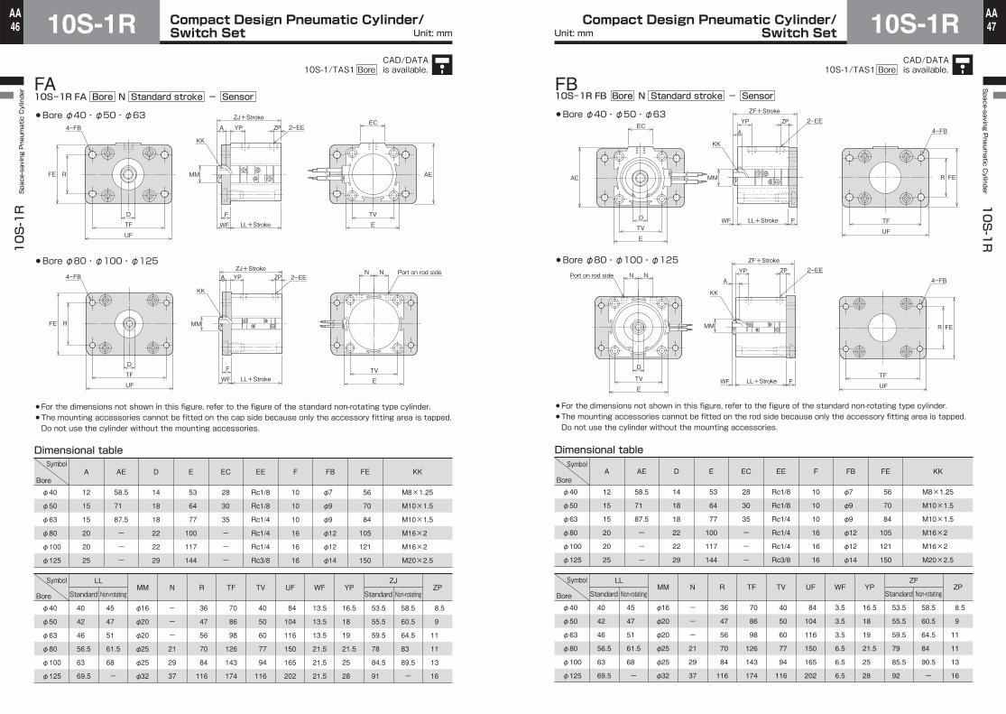
10S-1R FA Bore N Standard stroke - Sensor
Bore φ40・φ50・φ63
Bore φ80・φ100・φ125
For the dimensions not shown in this figure, refer to the figure of the standard non-rotating type cylinder.The mounting accessories cannot be fitted on the cap side because only the accessory fitting area is tapped.Do not use the cylinder without the mounting accessories.
AF
AE
4ーFB
D
TV
E
ZPYP
A
ZF+Stroke
LL+Stroke
2ーEE
KK
MM
FWF TF
UF
EC
R FE
R FE
4ーFB
TF
UF
ZPYPA
ZF+Stroke
LL+Stroke
2ーEE
KK
MM
FWF
N N
TV
E
Port on rod side
D
Dimensional table
12
15
15
20
20
25
A
58.5
71
87.5
-
-
-
AE
14
18
18
22
22
29
D
53
64
77
100
117
144
E
10
10
10
16
16
16
F
28
30
35
-
-
-
EC
56
70
84
105
121
150
FE
φ7
φ9
φ9
φ12
φ12
φ14
FB
Rc1/8
Rc1/8
Rc1/4
Rc1/4
Rc1/4
Rc3/8
EE
-
-
-
21
29
37
N
φ16
φ20
φ20
φ25
φ25
φ32
MM
M8×1.25
M10×1.5
M10×1.5
M16×2
M16×2
M20×2.5
KK
φ40
φ50
φ63
φ80
φ100
φ125
84
104
116
150
165
202
UF
40
50
60
77
94
116
TV
70
86
98
126
143
174
TF
36
47
56
70
84
116
R
3.5
3.5
3.5
6.5
6.5
6.5
WF YP
8.5
9
11
11
13
16
ZP
16.5
18
19
21.5
25
28
53.5
55.5
59.5
79
85.5
92
58.5
60.5
64.5
84
90.5
-
ZF
Standard Non-rotating
40
42
46
56.5
63
69.5
45
47
51
61.5
68
-
LL
φ40
φ50
φ63
φ80
φ100
φ125
10S-1R FB Bore N Standard stroke - Sensor
Bore φ40・φ50・φ63
Bore φ80・φ100・φ125
For the dimensions not shown in this figure, refer to the figure of the standard non-rotating type cylinder.The mounting accessories cannot be fitted on the rod side because only the accessory fitting area is tapped.Do not use the cylinder without the mounting accessories.
FB
Symbol
Standard Non-rotatingBore
Symbol
Bore
CAD/DATAis available.10S-1/TAS1 Bore
CAD/DATAis available.10S-1/TAS1 Bore
Unit: mm Unit: mm
Compact Design Pneumatic Cylinder/Switch Set10S-1R
10S-1R Space-saving Pneumatic Cylinder
48AA Compact Design Pneumatic Cylinder/
Switch Set 10S-1RSpace-saving P
neumatic C
ylinder 10S-1R
49AA
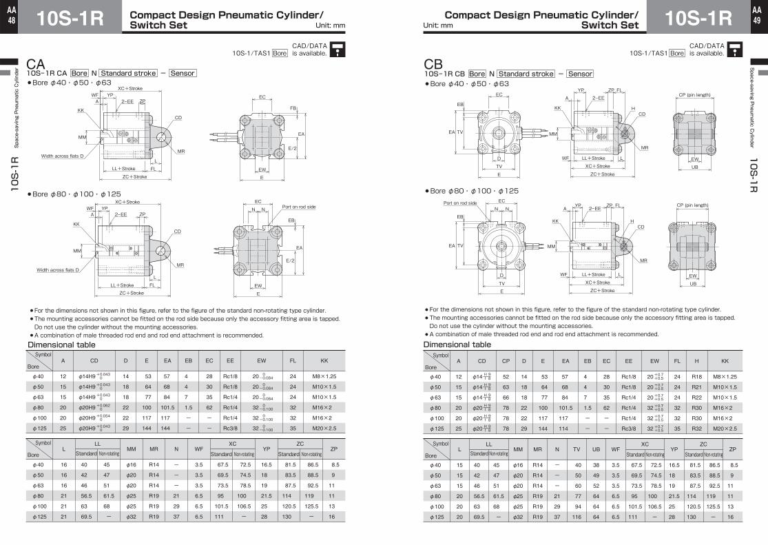
10S-1R CA Bore N Standard stroke - SensorCA
2ーEE
XC+Stroke
ZC+Stroke
LL+Stroke
ZPYPWF
A
KK
Width across flats D
MM
L
FL
CD
MR
EC
EW
E
FB
E/2
EA
2ーEE
XC+Stroke
ZPYPWF
A
KK
Width across flats D
MM
ZC+StrokeLL+Stroke
L
FL
CD
MR
EB
E/2
EA
EW
E
N N
ECPort on rod side
Dimensional table
12
15
15
20
20
25
A
14
18
18
22
22
29
D
53
64
77
100
117
144
E
57
68
84
101.5
117
144
EA
4
4
7
1.5
-
-
EB
28
30
35
62
-
-
EC
24
24
24
32
32
35
FL
20
20
20
32
32
32
EW
Rc1/8
Rc1/8
Rc1/4
Rc1/4
Rc1/4
Rc3/8
EE
-
-
-
21
29
37
N
φ16
φ20
φ20
φ25
φ25
φ32
MML
M8×1.25
M10×1.5
M10×1.5
M16×2
M16×2
M20×2.5
KK
φ40
φ50
φ63
φ80
φ100
φ125
3.5
3.5
3.5
6.5
6.5
6.5
WF
R14
R14
R14
R19
R19
R19
PYRM
8.5
9
11
11
13
16
ZP
16.5
18
19
21.5
25
28
67.5
69.5
73.5
95
101.5
111
72.5
74.5
78.5
100
106.5
-
XC
Standard Non-rotating
81.5
83.5
87.5
114
120.5
130
86.5
88.5
92.5
119
125.5
-
ZC
Standard Non-rotating
40
42
46
56.5
63
69.5
16
16
16
21
21
21
45
47
51
61.5
68
-
LL
φ40
φ50
φ63
φ80
φ100
φ125
0-0.084
0-0.084
0-0.084
0-0.100
0-0.100
0-0.100
φ14H9
φ14H9
φ14H9
φ20H9
φ20H9
φ20H9
CD
+0.043 0
+0.043 0
+0.043 0
+0.062 0
+0.054 0
+0.043 0
For the dimensions not shown in this figure, refer to the figure of the standard non-rotating type cylinder.The mounting accessories cannot be fitted on the rod side because only the accessory fitting area is tapped.Do not use the cylinder without the mounting accessories.A combination of male threaded rod end and rod end attachment is recommended.
Bore φ40・φ50・φ63
Bore φ80・φ100・φ125
Symbol
Standard Non-rotatingBore
Symbol
Bore
YP
A
ZP FL
LL+Stroke
XC+Stroke
ZC+Stroke
LL+Stroke
XC+Stroke
ZC+Stroke
2ーEE
KK
MM
LFW
CDH
MR
EC
TV
EB
EA
D
TV
E
EW
UB
CP (pin length)
CP (pin length)
YPA
ZP FL2ーEE
KK
MM
LFW
CDH
MR
EW
UB
EB
TVEA
N N
EC
D
TV
E
Port on rod side
Dimensional table
12
15
15
20
20
25
A
14
18
18
22
22
29
D
52
63
66
78
78
78
CP
53
64
77
100
117
144
E
57
68
84
101.5
117
114
EA
4
4
7
1.5
-
-
EB
28
30
35
62
-
-
EC
24
24
24
32
32
35
FL
R18
R21
R22
R30
R30
R32
H
Rc1/8
Rc1/8
Rc1/4
Rc1/4
Rc1/4
Rc3/8
EE
-
-
-
21
29
37
N
φ16
φ20
φ20
φ25
φ25
φ32
MML
M8×1.25
M10×1.5
M10×1.5
M16×2
M16×2
M20×2.5
KK
φ40
φ50
φ63
φ80
φ100
φ125
3.5
3.5
3.5
6.5
6.5
6.5
WF
40
50
60
77
94
116
TV
38
49
52
64
64
64
UB
R14
R14
R14
R19
R19
R19
PYRM
8.5
9
11
11
13
16
ZP
16.5
18
19
21.5
25
28
40
42
46
56.5
63
69.5
15
15
15
20
20
20
45
47
51
61.5
68
-
LL
81.5
83.5
87.5
114
120.5
130
86.5
88.5
92.5
119
125.5
-
ZC
Standard Non-rotating
67.5
69.5
73.5
95
101.5
111
72.5
74.5
78.5
100
106.5
-
XC
Standard Non-rotating
φ40
φ50
φ63
φ80
φ100
φ125
20
20
20
32
32
32
EW
+0.7+0.5
+0.7+0.5
+0.7+0.5
+0.7+0.5
+0.7+0.5
+0.7+0.5
φ14
φ14
φ14
φ20
φ20
φ20
CD
H 9 f 8
H 9 f 8
H 9 f 8
H 9 f 8
H 9 f 8
H 9 f 8
10S-1R CB Bore N Standard stroke - SensorBore φ40・φ50・φ63
Bore φ80・φ100・φ125
BC
Symbol
Standard Non-rotatingBore
Symbol
Bore
For the dimensions not shown in this figure, refer to the figure of the standard non-rotating type cylinder.The mounting accessories cannot be fitted on the rod side because only the accessory fitting area is tapped.Do not use the cylinder without the mounting accessories.A combination of male threaded rod end and rod end attachment is recommended.
CAD/DATAis available.10S-1/TAS1 Bore
CAD/DATAis available.10S-1/TAS1 Bore
Unit: mm Unit: mm

Compact Design Pneumatic Cylinder/Switch Set10S-1R
10S-1R Space-saving Pneumatic Cylinder
50AA Compact Design Pneumatic Cylinder/
Switch Set 10S-1RSpace-saving P
neumatic C
ylinder 10S-1R
51AA
21UX1 UX2 21UX1 UX2
21UX1 UX2 21UX1 UX2
21UX1 UX2 21UX1 UX2
UX1 UX223 UX1 UX223
UX1 UX223 UX1 UX223
10S-1R Mounting style Bore N Stroke Sensor symbol Sensor quantitySwitch Set
ZR and ZS type sensor
KS type sensor
Bore φ12 to φ32 Double acting single rod Double acting double rod
Bore φ40 to φ63
Bore φ80 to φ125
Bore φ40・φ50・φ63 Double acting single rod Double acting double rod
Bore φ80・φ100・φ125
Note) Dimension UX indicates the optimum sensor fitting position for detection of stroke end.
Note) ZR2 and ZS2 types are designed for cylinder bores of φ12 to φ32, and ZR3 and ZS3 types for φ40 to φ125.
Dimensional table
5
7
8
8
9
15
18
17
16
23
22
5
7
8
8
9
15
18
17
16
23
22
-
-
18
18
19
20
23
22
21
28
-
Bore Reed sensor
Solid state sensor Reed sensor Solid state sensor
UX1
Standard Double rod Non-rotating Standard Double rod Non-rotating Standard Double rod Non-rotating Standard Double rod Non-rotating Standard Double rod Non-rotating Standard Double rod Non-rotating
5
7
9
8
10
15
17
16
17
25
23
5
7
9
8
10
15
17
16
17
25
23
-
-
19
18
20
20
22
21
22
30
-
ZS type
1
1
1
3
3
5
7
8
14
15
20
10
10
11
12
12
19
20
23
28
31
34
-
-
1
3
3
5
7
8
14
15
-
ZR type
-
-
-
-
-
15
17
18
20
25
26
-
-
-
-
-
15
17
18
20
25
26
-
-
-
-
-
20
22
23
25
30
-
KS type
1
1
1
2
3
3
3
8
14
15
20
10
10
11
12
14
17
16
23
28
31
34
-
-
1
2
3
3
3
8
14
15
-
ZS type
-
-
-
-
-
5
5
8
17
19
24
-
-
-
-
-
19
20
23
32
33
40
-
-
-
-
-
5
5
8
17
19
-
KS type
UX2
Operating range and hysteresis
5 to 13
4 to 12
10 to 18
14 to 20
17 to 24
2 to 10
4 to 12
5 to 13
6 to 14
8 to 16
9 to 17
4 to 12
5 to 13
7 to 15
10 to 18
12 to 18
2 or less 1 or less
-
1 or less
Bore ZR2 and ZS3 type ZS2 and ZS3 type
Operating range Hysteresis Operating range Hysteresis Opetating range Hysteresis
KS type
φ12
φ16
φ20
φ25
φ32
φ40
φ50
φ63
φ80
φ100
φ125
φ12
φ16
φ20
φ25
φ32
φ40
φ50
φ63
φ80
φ100
φ125
Sensor mountable minimum stroke
5
5
5
5
5
5
5
5
5
5
5
5
5
5
5
5
5
5
5
5
5
5
BoreWith 1 sensor
ZR type KS type KS type ZR type KS type KS type
10
10
10
10
10
10
10
10
10
10
15
10
10
10
10
10
10
10
10
10
10
10
10
10
10
10
10
10
10
10
10
10
10
With 2 sensors
20
20
20
20
20
20
20
20
20
20
25
φ12
φ16
φ20
φ25
φ32
φ40
φ50
φ63
φ80
φ100
φ125
Reed sensor Solid state sensor
Unit: mm Unit: mm

Compact Design Pneumatic Cylinder/Switch Set10S-1R
10S-1R Space-saving Pneumatic Cylinder
52AA Compact Design Pneumatic Cylinder/
Switch Set 10S-1RSpace-saving P
neumatic C
ylinder 10S-1R
53AA
Set screw
Sensor rail
Slide the sensor to any position.
Slide the sensor to any position.
Bracket screw
Bracket mounting groove
Bracket (T02)
Slide the sensor to any position.
Bracket screwBracket (type: T05)
Setting method of sensor detecting position
ZR2 type and ZS2 typeTightening torque: Approx. 0.2 N・m
KS typeTightening torque: Approx. 0.4 N・m
ZR3 type and ZS3 typeTightening torque: Approx. 0.4 N・m
1.To detect the cylinder stroke end, set the sensor cable toward the center of the cylinder.2.Slide the sensor to any detecting position. To detect the cylinder stroke end, fit the sensor at the position indicated by UX.
Dimensional table
LNA-05Z-A
LNA-08Z-A
LNA-12Z-A
LNA-16Z-A
LNA-20Z-A
LNA-27Z-A
Lock nutpart number A
8
8
13
13
19
19
22
22
27
27
36
B1
3.5
3.5
3.5
3.5
3.5
3.5
3.5
3.5
5
5
5
C
5
5
8
8
14
14
18
18
22
22
29
D
3.2
3.2
5
5
7
7
10
10
12
12
16
h
-
-
9
9
14
14
19
19
23
23
-
3.5
3.5
5
5
5
5
5
5
6.5
6.5
6.5
-
-
-
-
-
15
15
15
21.5
21.5
21.5
MG
φ6
φ6
φ10
φ10
φ16
φ16
φ20
φ20
φ25
φ25
φ32
MMWF
SD・ST style FA style
M5×0.8
M5×0.8
M8×1.25
M8×1.25
M12×1.25
M12×1.25
M16×1.5
M16×1.5
M20×1.5
M20×1.5
M27×2
KK
φ12
φ16
φ20
φ25
φ32
φ40
φ50
φ63
φ80
φ100
φ125
Dimensional table
φ13H8
φ17H8
φ22H8
φ26H8
φ34H8
φ42H8
φ52H8
φ65H8
φ82H8
φ102H8
φ130H8
-
-
-
-
-
φ30
φ37.5
φ40.5
φ50
φ55
-
1.5
1.5
1.9
1.7
2
3.5
4
5
4.5
5.8
7
A1
-
-
φ13
φ16
φ22.5
φ29.5
φ36
φ36
φ50
φ55
φ60
Standard Non-rotating
BC1
Symbol
Boreφ12
φ16
φ20
φ25
φ32
φ40
φ50
φ63
φ80
φ100
φ125
0-0.1
0-0.1
0-0.1
0-0.1
0-0.1
0-0.1
0-0.1
0-0.1
0-0.1
0-0.1
0-0.1
BA1
C1
Cross section of body and bush
10(8.5)
10(8.5)
16(13.5)
16(13.5)
24(21.5)
24(21.5)
32(29)
32(29)
40(37)
40(37)
54(50)
*The parenthesized values of dimension A are the lengths of threaded portions.
C
A WF
h
MM
KK
Width across flats D
Lock nut for rod end attachmentWidth across flats B1
A WF
h
Hex. rodWidth acrossflats MG
KK
Lock nut for rod end attachmentWidth across flats B1
WF
Rod end male thread
Standard(Bore φ12 to φ125)
Non-rotating(Bore φ20 to φ100)
Double acting single rod Double acting double rod
When FA style is used, the dimension WF is longer. Check the dimension when placing an order for the mounting accessory.
In the case of FA style
C C
A WF
h
AWF+Stroke
MM
2ーKK
Width across flats DLock nut for rod end attachmentWidth across flats B1
Symbol
Bore
Unit: mm

Compact Design Pneumatic Cylinder/Switch Set10S-1R
10S-1R Space-saving Pneumatic Cylinder
54AA Compact Design Pneumatic Cylinder/
Switch Set 10S-1RSpace-saving P
neumatic C
ylinder 10S-1R
55AA
CF
EW
KK
R12 spherical
7 CA
RA
CD
ACC
CF
RA
CA
ER
CD
Width acrossflats
ACC
EW
KK
ACD
EW
J
RA
45°
CF KK
CC
CAER
TACDCN
TW
DK
TVGW 4°
KK
CFED
CM CA
CN
Lubricating port
R12spherical
Pin fitting
CF
7 CARA
EWCT
CD
KK
CC A
RA
CA
ER
CDD
Width acrossflats
Width acrossflatsKK
CF
CC A
CW
CW
EWCTCP
RA
CA
ER
CD
D
KK
CF
A
CW
CWEWCTCP
CC
CF
RA
CD
EWCT
PF
CP
CACL
KK
Split pin
ACC
Rod end attachment
φ12・φ16 φ20・φ25 φ32 to φ100 φ125
521φφ32 to φ10061φ・21φ
φ20 to φ100
Rod eye (T-end)
D
Rod eye with spherical bearing (S-end)
Rod clevis (Y-end) with pin
Washer
Dimensional table
RTA-05-A
RTA-12-A
RTA-16-A
RTA-20-A
RTA-27-A
Part number
8
8
25
25
33
33
41
41
56
A
25
25
60
60
60
60
85
85
100
CA
14
14
20
20
20
20
30
30
32
CC
φ5.1
φ5.1
φ14H9
φ14H9
φ14H9
φ14H9
φ20H9
φ20H9
φ20H9
CD
□12
□12
φ24
φ24
φ28
φ28
φ36
φ36
φ49
CF
-
-
24
24
27
27
36
36
-
D
-
-
R12
R12
R14
R14
R19
R19
20
ER
-
-
-
-
-
-
-
-
13
J
32
32
72
72
74
74
104
104
120
RA
6.4
6.4
20
20
20
20
32
32
32
EW
M5×0.8
M5×0.8
M12×1.25
M12×1.25
M16×1.5
M16×1.5
M20×1.5
M20×1.5
M27×2
KKSymbol
Boreφ12
φ16
φ32
φ40
φ50
φ63
φ80
φ100
φ125
0-0.1
0-0.1
0-0.1
0-0.1
0-0.1
0-0.1
0-0.1
Dimensional table
RSA-08-A
RSA-12-A
RSA-16-A
RSA-20-A
36
36
50
50
64
64
77
77
CA
11
11
15
15
19
19
23
23
CM
47
47
65
65
83
83
100
100
CN
φ10.4
φ10.4
φ15.4
φ15.4
φ19.4
φ19.4
φ24.4
φ24.4
DK
22
22
30
30
38
38
46
46
ED
φ8H9
φ8H9
φ12H9
φ12H9
φ16H9
φ16H9
φ20H9
φ20H9
CD
φ16
φ16
φ22
φ22
φ27
φ27
φ34
φ34
CF
17
17
24
24
33
33
40
40
TA
9±0.1
9±0.1
12±0.1
12±0.1
15±0.1
15±0.1
18±0.1
18±0.1
TV
14
14
19
19
22
22
30
30
TW
12
12
16
16
21
21
25
25
GW
M8×1.25
M8×1.25
M12×1.25
M12×1.25
M16×1.5
M16×1.5
M20×1.5
M20×1.5
KK
φ20
φ25
φ32
φ40
φ50
φ63
φ80
φ100
0-0.1
0-0.1
0-0.1
0-0.1
0-0.1
0-0.1
0-0.1
0-0.1
Dimensional table
RYA-05-A
RYA-08-A
RYA-12-1-A
RYA-16-A
RYA-20-A
RYA-27-A
11
11
16
16
25
25
33
33
41
41
56
A
21
21
32
32
60
60
60
60
85
85
100
CA
10
10
16
16
20
20
18
18
28
28
35
CC
□12
□12
□16
□16
44
44
44
44
64
64
64
CT
φ12
φ12
φ14
φ14
φ24
φ24
φ28
φ28
φ36
φ36
φ40
CF
φ5.1
φ5.1
φ8
φ8
φ14
φ14
φ14
φ14
φ20
φ20
φ20
CD
-
-
10
10
-
-
-
-
-
-
-
CL
-
-
24.5
24.5
58
58
58
58
78
78
78
CP
-
-
-
-
12
12
12
12
16
16
16
CW
-
-
-
-
24
24
27
27
36
36
40
D
-
-
-
-
R12
R12
R14
R14
R19
R19
R20
ER
-
-
2
2
-
-
-
-
-
-
-
PF
28
28
42
42
72
71
74
74
104
104
120
RA
6.5
6.5
8
8
20
20
20
20
32
32
32
EW
M5×0.8
M5×0.8
M8×1.25
M8×1.25
M12×1.25
M12×1.25
M16×1.5
M16×1.5
M20×1.5
M20×1.5
M27×2
KK
φ12
φ16
φ20
φ25
φ32
φ40
φ50
φ63
φ80
φ100
φ125
+0.4+0.1
+0.4+0.1
+1.5+0.5
+1.5+0.5
+1.5+0.5
+1.5+0.5
+1.5+0.5
+1.5+0.5
+1.5+0.5
H 8 f 7
H 8 f 7
H 9 f 8
H 9 f 8
H 9 f 8
H 9 f 8
H 9 f 8
H 9 f 8
H 9 f 8
Part numberSymbol
Bore
Part numberSymbol
Bore
CAD/DATAis available.10S-1/TAS1 Bore
Unit: mm Unit: mm
Compact Design Pneumatic Cylinder/Switch Set10S-1R
10S-1R Space-saving Pneumatic Cylinder
56AA Compact Design Pneumatic Cylinder/
Switch Set 10S-1RSpace-saving P
neumatic C
ylinder 10S-1R
57AA
5°
5° FN
KK
FM
FK
FR
A FQ
FA FC
FJ
FD
e
e
KK
Rotating angle
Eccentricity 5°
5°
KK
FM
FK
FR
A FQ
FA FC
FJ
FD
e
e
KKFN
US
E
L
LH
TV
TU
SASZSU
ST
H Z
2-SB
2ーSQ
R
TR
AU AZ
AO
2ーSB
UA
AH
TR
R
AT
H Z
2ーSQ
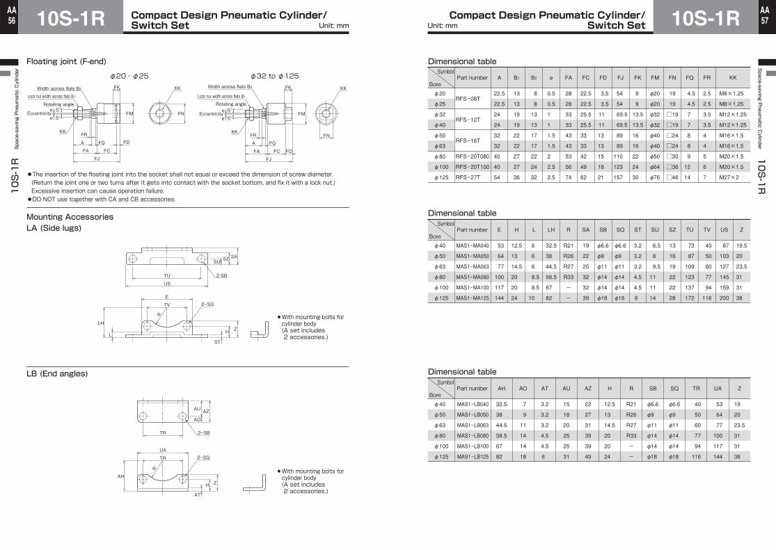
Floating joint (F-end)
φ20・φ25 φ32 to φ125
Mounting AccessoriesLA (Side lugs)
Width across flats B2Lock nut width across flats B1
Rotating angle
Eccentricity
Width across flats B2
Lock nut width across flats B1
LB (End angles)
●The insertion of the floating joint into the socket shall not equal or exceed the dimension of screw diameter. (Return the joint one or two turns after it gets into contact with the socket bottom, and fix it with a lock nut.) Excessive insertion can cause operation failure.●DO NOT use together with CA and CB accessories.
With mounting bolts forcylinder body(A set includes 2 accessories.)
With mounting bolts forcylinder body(A set includes 2 accessories.)
Dimensional table
RFS-08T
RFS-12T
RFS-16T
RFS-20T080
RFS-20T100
RFS-27T
22.5
22.5
24
24
32
32
40
40
54
A
0.5
0.5
1
1
1.5
1.5
2
2.5
2.5
e
28
28
33
33
43
43
53
56
74
FA
22.5
22.5
25.5
25.5
33
33
42
49
62
FC
3.5
3.5
11
11
13
13
15
18
21
FD
54
54
69.5
69.5
89
89
110
123
157
FJ
9
9
13.5
13.5
16
16
22
24
30
FK
φ20
φ20
φ32
φ32
φ40
φ40
φ50
φ64
φ76
FM
19
19
□19
□19
□24
□24
□30
□36
□46
FN
4.5
4.5
7
7
8
8
9
12
14
FQ
2.5
2.5
3.5
3.5
4
4
5
6
7
FR
13
13
19
19
22
22
27
27
36
B1
8
8
13
13
17
17
22
24
32
B2
M8×1.25
M8×1.25
M12×1.25
M12×1.25
M16×1.5
M16×1.5
M20×1.5
M20×1.5
M27×2
KK
φ20
φ25
φ32
φ40
φ50
φ63
φ80
φ100
φ125
Dimensional table
MAS1-MA040
MAS1-MA050
MAS1-MA063
MAS1-MA080
MAS1-MA100
MAS1-MA125
53
64
77
100
117
144
E
12.5
13
14.5
20
20
24
H
6
6
6
8.5
8.5
10
L
32.5
38
44.5
58.5
67
82
LH
R21
R26
R27
R33
-
-
R
19
22
25
32
32
39
SA
φ6.6
φ9
φ11
φ14
φ14
φ18
φ6.6
φ9
φ11
φ14
φ14
φ18
SB SQ
3.2
3.2
3.2
4.5
4.5
6
ST
6.5
8
9.5
11
11
14
SU
13
16
19
22
22
28
SZ
73
87
109
123
137
172
TU
40
50
60
77
94
116
TV
87
103
127
145
159
200
US
19.5
20
23.5
31
31
38
Z
φ40
φ50
φ63
φ80
φ100
φ125
Dimensional table
MAS1-LB040
MAS1-LB050
MAS1-LB063
MAS1-LB080
MAS1-LB100
MAS1-LB125
32.5
38
44.5
58.5
67
82
AH
7
9
11
14
14
18
AO
3.2
3.2
3.2
4.5
4.5
6
AT
15
18
20
25
25
31
AU
22
27
31
39
39
49
AZ
12.5
13
14.5
20
20
24
H
R21
R26
R27
R33
-
-
R
φ6.6
φ9
φ11
φ14
φ14
φ18
φ6.6
φ9
φ11
φ14
φ14
φ18
SB SQ
40
50
60
77
94
116
TR
53
64
77
100
117
144
UA
19
20
23.5
31
31
38
Z
φ40
φ50
φ63
φ80
φ100
φ125
Part numberSymbol
Bore
Part numberSymbol
Bore
Part numberSymbol
Bore
Unit: mm Unit: mm

Compact Design Pneumatic Cylinder/Switch Set10S-1R
10S-1R Space-saving Pneumatic Cylinder
58AA Compact Design Pneumatic Cylinder/
Switch Set 10S-1RSpace-saving P
neumatic C
ylinder 10S-1R
59AA
UF
TF F
TV
FE R TVZ
4ーFB
E
TV
EW
FL
T
L
ETV
MR
4ーSQ
CD
MR
4ーSB
CDH
L
Z
FL
CP
UB
T
E
TV
ETV
EW
FA (Rod rectangular flange)・FB (Cap rectangular flange)
CA (Cap eye)
4-SB, throughSpot facing diameter SQ, depth SP
CB (Cap clevis with pin)
With mounting bolts forcylinder body
With mounting bolts forcylinder body
With mounting bolts forcylinder body
Dimensional table
MAS1-FA040
MAS1-FA050
MAS1-FA063
MAS1-FA080
MAS1-FA100
MAS1-FA125
10
10
10
16
16
16
F
φ7
φ9
φ9
φ12
φ12
φ14
FB
56
70
84
105
121
150
FE
36
47
56
70
84
116
R
φ6.6
φ9
φ11
φ14
φ14
φ18
SB
4.5
5.5
6.5
7.5
7.5
9
SP
11
15
19
22
22
29
SQ
70
86
98
126
143
174
TF
40
50
60
77
94
116
TV
84
104
116
150
165
202
UF
φ30
φ37
φ41
φ51
φ56
φ61
Z
φ40
φ50
φ63
φ80
φ100
φ125
Dimensional table
MAS1-CA040
MAS1-CA050
MAS1-CA063
MAS1-CA080
MAS1-CA100
MAS1-CA125
φ14H9
φ14H9
φ14H9
φ20H9
φ20H9
φ20H9
CD
53
64
77
100
117
144
E
20
20
20
32
32
32
EW
24
24
24
32
32
35
FL
16
16
16
21
21
21
L
R14
R14
R14
R19
R19
R19
MR
φ6.6
φ9
φ11
φ14
φ14
φ18
SQ
6.5
6.5
6.5
9.5
9.5
12.5
T
40
50
60
77
94
116
TV
φ40
φ50
φ63
φ80
φ100
φ125
+0.043 0
+0.043 0
+0.043 0
+0.062 0
+0.054 0
+0.043 0
0-0.084
0-0.084
0-0.084
0-0.100
0-0.100
0-0.100
Dimensional table
MAS1-CB040
MAS1-CB050
MAS1-CB063
MAS1-CB080
MAS1-CB100
MAS1-CB125
CD
53
64
77
100
117
144
E
52
63
66
78
78
78
CP
20
20
20
32
32
32
EW
24
24
24
32
32
35
FL
R18
R21
R22
R30
R30
R32
H
15
15
15
20
20
20
L
R14
R14
R14
R19
R19
R19
MR
φ6.6
φ9
φ11
φ14
φ14
φ18
SB
38
49
52
64
64
64
UB
40
50
60
77
94
116
TV
7.5
7.5
7.5
10.5
10.5
13.5
T
38
38
38
51
51
54
Z
φ40
φ50
φ63
φ80
φ100
φ125
+0.7+0.5
+0.7+0.5
+0.7+0.5
+0.7+0.5
+0.7+0.5
+0.7+0.5
φ14
φ14
φ14
φ20
φ20
φ20
H 9 f 8
H 9 f 8
H 9 f 8
H 9 f 8
H 9 f 8
H 9 f 8
Part numberSymbol
Bore
Part numberSymbol
Bore
Part numberSymbol
Bore
Unit: mm Unit: mm
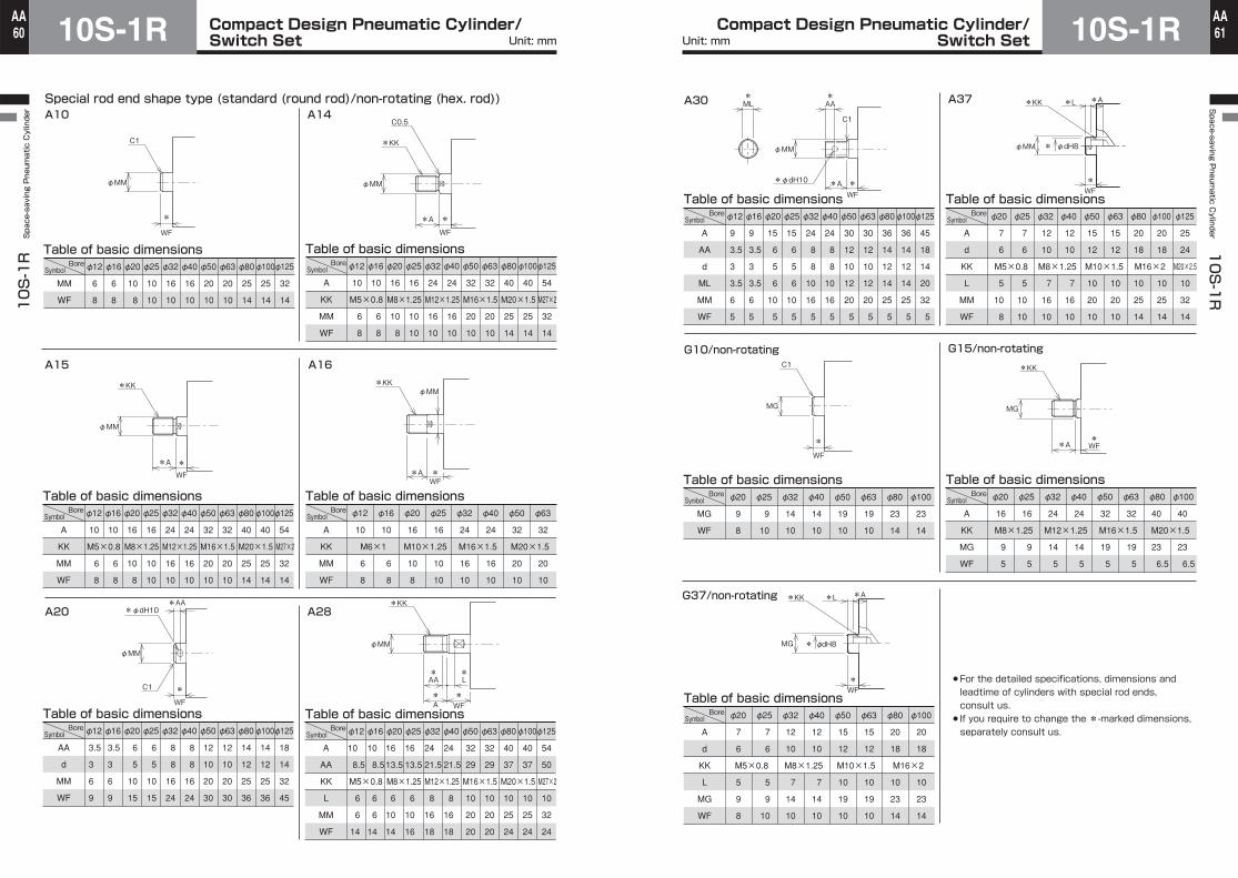
Compact Design Pneumatic Cylinder/Switch Set10S-1R
10S-1R Space-saving Pneumatic Cylinder
60AA Compact Design Pneumatic Cylinder/
Switch Set 10S-1RSpace-saving P
neumatic C
ylinder 10S-1R
61AA
6
8
φ12
6
8
φ16
10
8
φ20
10
10
φ25
16
10
φ32
16
10
φ40
20
10
φ50
20
10
φ63
25
14
φ80
25
14
φ100
32
14
φ125SymbolBore
MM
WF
Table of basic dimensions
10
6
8
M5×0.8 M8×1.25 M12×1.25 M16×1.5 M20×1.5 M27×2
10
6
8
φ12φ16
16
10
8
16
10
10
φ20φ25
24
16
10
24
16
10
φ32φ40
32
20
10
32
20
10
φ50φ63
40
25
14
40
25
14
φ80φ100
54
32
14
φ125SymbolBore
A
KK
MM
WF
Table of basic dimensions
10
6
8
M5×0.8 M8×1.25 M12×1.25 M16×1.5 M20×1.5 M27×2
10
6
8
φ12φ16
16
10
8
16
10
10
φ20φ25
24
16
10
24
16
10
φ32φ40
32
20
10
32
20
10
φ50φ63
40
25
14
40
25
14
φ80φ100
54
32
14
φ125
A
KK
MM
WF
Table of basic dimensions
10
6
8
M6×1 M10×1.25 M16×1.5 M20×1.5
10
6
8
φ12 φ16
16
10
8
16
10
10
φ20 φ25
24
16
10
24
16
10
φ32 φ40
32
20
10
32
20
10
φ50 φ63SymbolBore
A
KK
MM
WF
Table of basic dimensions
3.5
3
6
9
3.5
3
6
9
φ12φ16
6
5
10
15
6
5
10
15
φ20φ25
8
8
16
24
8
8
16
24
φ32φ40
12
10
20
30
12
10
20
30
φ50φ63
14
12
25
36
14
12
25
36
φ80φ100
18
14
32
45
φ125
AA
d
MM
WF
10
8.5
6
6
14
10
8.5
6
6
14
M5×0.8 M8×1.25 M12×1.25 M16×1.5 M20×1.5 M27×2
φ12φ16
16
13.5
6
10
14
16
13.5
6
10
16
φ20φ25
24
21.5
8
16
18
24
21.5
8
16
18
φ32φ40
32
29
10
20
20
32
29
10
20
20
φ50φ63
40
37
10
25
24
40
37
10
25
24
φ80φ100
54
50
10
32
24
φ125SymbolBore
A
AA
KK
L
MM
WF
Table of basic dimensions
Special rod end shape type (standard (round rod)/non-rotating (hex. rod))41A01A
61A51A
82A02A
φMM
C1
*
WF
φMM
C0.5
*KK
*A *
WF
φMM
*KK
*WF
*A
φMM*KK
*WF
*A
C1
φMM
*φdH10*AA
*
WF* A
* WF
φMM
*KK
* AA
* L
SymbolBore
SymbolBore
Table of basic dimensions
9
3.5
3
3.5
6
5
9
3.5
3
3.5
6
5
φ12φ16
15
6
5
6
10
5
15
6
5
6
10
5
φ20φ25
24
8
8
10
16
5
24
8
8
10
16
5
φ32φ40
30
12
10
12
20
5
30
12
10
12
20
5
φ50φ63
36
14
12
14
25
5
36
14
12
14
25
5
45
18
14
20
32
5
φ80φ100φ125SymbolBore
A
AA
d
ML
MM
WF
Table of basic dimensions
M5×0.8 M8×1.25 M10×1.5 M16×2 M20×2.5
7
6
5
10
8
7
6
5
10
10
φ20 φ25
12
10
7
16
10
12
10
7
16
10
φ32 φ40
15
12
10
20
10
15
12
10
20
10
φ50 φ63
20
18
10
25
14
20
18
10
25
14
φ80 φ100
25
24
10
32
14
φ125
A
d
KK
L
MM
WF
Table of basic dimensions
9
8
9
10
φ20 φ25
14
10
14
10
φ32 φ40
19
10
19
10
φ50 φ63
23
14
23
14
φ80 φ100
MG
WF
Table of basic dimensions
16
9
5
16
9
5
M8×1.25 M12×1.25 M16×1.5 M20×1.5
φ20 φ25
24
14
5
24
14
5
φ32 φ40
32
19
5
32
19
5
φ50 φ63
40
23
6.5
40
23
6.5
φ80 φ100
A
KK
MG
WF
Table of basic dimensions
7
6
5
9
8
7
6
5
9
10
M5×0.8 M8×1.25 M10×1.5 M16×2
φ20 φ25
12
10
7
14
10
12
10
7
14
10
φ32 φ40
15
12
10
19
10
15
12
10
19
10
φ50 φ63
20
18
10
23
14
20
18
10
23
14
φ80 φ100
A
d
KK
L
MG
WF
Table of basic dimensions
73A03A
G37/non-rotating
φMM
C1
*φdH10 * WF
*A
*AA
*ML
φMM * φdH8
*L*KK *A
* WF
MG
C1
*
WF
* WF*A
MG
*KK
MG * φdH8
*L*KK *A
* WF
For the detailed specifications, dimensions and leadtime of cylinders with special rod ends, consult us.If you require to change the *-marked dimensions, separately consult us.
G15/non-rotatingG10/non-rotating
SymbolBore
SymbolBore
SymbolBore
SymbolBore
Unit: mm Unit: mm

Compact Design Pneumatic Cylinder/Switch Set10S-1R
10S-1R Space-saving Pneumatic Cylinder
62AA Compact Design Pneumatic Cylinder/
Switch Set 10S-1RSpace-saving P
neumatic C
ylinder 10S-1R
63AA
Switch Set/standard (10S-1R)Cylinder bore
StrokeSeries variations
10S-1R
10S-1RD
10S-1RG
10S-1RSR
6.5 6.510.5 9.510.510.5 9.512.615 15 20 6.5 6.510.5 9.510.510.5 9.512.615 15 20 6.5 6.510.5 9.510.510.5 9.5
k
CBT3-35SCBT3-35SCBT5-40SCBT5-40SCBT5-45SCBT5-50D
- - - - -
CBT3-45SCBT3-45SCBT5-50SCBT5-50SCBT5-55SCBT5-65D
- - - - -
CBT3-35SCBT3-35SCBT5-40SCBT5-40SCBT5-45SCBT5-50D
-
5CBT3-40SCBT3-40SCBT5-45SCBT5-45SCBT5-50SCBT5-55DCBT6-55DCBT8-60D
CBT10-65D CBT10-70D CBT12-80D
CBT3-50SCBT3-50SCBT5-55SCBT5-55SCBT5-60SCBT5-70DCBT6-70DCBT8-75D
CBT10-80D CBT10-85D CBT12-95D
CBT3-40SCBT3-40SCBT5-45SCBT5-45SCBT5-50SCBT5-55DCBT6-55D
10CBT3-45SCBT3-45SCBT5-50SCBT5-50SCBT5-55SCBT5-60DCBT6-60DCBT8-65D
CBT10-70D CBT10-75D CBT12-85D
CBT3-55SCBT3-55SCBT5-60SCBT5-60SCBT5-65SCBT5-75DCBT6-75DCBT8-80D
CBT10-85D CBT10-90D
CBT12-100D - - - - - -
CBT6-60D
15CBT3-50SCBT3-50SCBT5-55SCBT5-55SCBT5-60SCBT5-65DCBT6-65DCBT8-70D
CBT10-75D CBT10-80D CBT12-90D
CBT3-60SCBT3-60SCBT5-65SCBT5-65SCBT5-70SCBT5-80DCBT6-80DCBT8-85D
CBT10-90D CBT10-95D
CBT12-105D - - - - - -
CBT6-65D
20φ12 φ16 φ20 φ25 φ32 φ40 φ50 φ63 φ80 φ100φ125φ12 φ16 φ20 φ25 φ32 φ40 φ50 φ63 φ80 φ100φ125φ12 φ16 φ20 φ25 φ32 φ40 φ50
Switch Set/non-rotating (10S-1RG)Cylinder boreSeries variations
10.5 9.510.510.5 9.512.615 15
k
CBT5-50SCBT5-50SCBT5-55SCBT5-55D
- - - -
5CBT5-55SCBT5-55SCBT5-60SCBT5-60DCBT6-60DCBT8-65D
CBT10-70D CBT10-75D
10CBT5-60SCBT5-60SCBT5-65SCBT5-65DCBT6-65DCBT8-70D
CBT10-75D CBT10-80D
15CBT5-65SCBT5-65SCBT5-70SCBT5-70DCBT6-70DCBT8-75D
CBT10-80D CBT10-85D
20φ20 φ25 φ32 φ40 φ50 φ63 φ80 φ100
k
Mounting bolt
Cylinder body
Bolt size
3
5
6
M3
M5
M6
8
10
12
M8
M10
M12
Quantity
S
D
2 pcs.
4 pcs.
CBT 5 - 80 S
Part number
Mounting bolt type
Bolt size
Quantity❷
Bolt length( )
Double actingsingle rod
Double actingdouble rod
Single acting type(spring return)
Double actingsingle rod
Stroke
❶
❶❷
Stroke
CBT3-55SCBT3-55SCBT5-60SCBT5-60SCBT5-65SCBT5-70DCBT6-70DCBT8-75D
CBT10-80D CBT10-85D CBT12-95D
CBT3-65SCBT3-65SCBT5-70SCBT5-70SCBT5-75SCBT5-85DCBT6-85DCBT8-90D
CBT10-95D CBT10-100D CBT12-110D
- - - - - --
25--
CBT5-65SCBT5-65SCBT5-70SCBT5-75DCBT6-75DCBT8-80D
CBT10-85D CBT10-90D
CBT12-100D --
CBT5-75SCBT5-75SCBT5-80SCBT5-90DCBT6-90DCBT8-95D
CBT10-100D CBT10-105D CBT12-115D
- - - - - --
30----
CBT5-75SCBT5-80DCBT6-80DCBT8-85D
CBT10-90D CBT10-95D
CBT12-105D ----
CBT5-85SCBT5-95DCBT6-95D
CBT8-100D CBT10-105D CBT10-110D CBT12-120D
- - - - - --
35----
CBT5-80SCBT5-85DCBT6-85DCBT8-90D
CBT10-95D CBT10-100D CBT12-110D
----
CBT5-90S CBT5-100D CBT6-100D CBT8-105D
CBT10-110D CBT10-115D CBT12-125D
- - - - - --
40----
CBT5-85SCBT5-90DCBT6-90DCBT8-95D
CBT10-100D CBT10-105D CBT12-115D
----
CBT5-95S CBT5-105D CBT6-105D CBT8-110D
CBT10-115D CBT10-120D CBT12-130D
- - - - - --
45----
CBT5-90SCBT5-95DCBT6-95D
CBT8-100D CBT10-105D CBT10-110D CBT12-120D
----
CBT5-100S CBT5-110D CBT6-110D CBT8-115D
CBT10-120D CBT10-125D CBT12-135D
- - - - - --
50
CBT5-70SCBT5-70SCBT5-75SCBT5-75DCBT6-75DCBT8-80D
CBT10-85D CBT10-90D
25CBT5-75SCBT5-75SCBT5-80SCBT5-80DCBT6-80DCBT8-85D
CBT10-90D CBT10-95D
30- -
CBT5-85SCBT5-85DCBT6-85DCBT8-90D
CBT10-95D CBT10-100D
35- -
CBT5-90SCBT5-90DCBT6-90DCBT8-95D
CBT10-100D CBT10-105D
40- -
CBT5-95SCBT5-95DCBT6-95D
CBT8-100D CBT10-105D CBT10-110D
45- -
CBT5-100S CBT5-100D CBT6-100D CBT8-105D
CBT10-110D CBT10-115D
50
The mounting bolts will shipped together with following standard stroke SD (basic style) cylinders.
Stroke
Note)When placing an order for SD (basic style) cylinders having strokes not listed in the following table, see the mounting bolt kit list shown on the left page, and separately place an order for the appropriate kit.Also in the following cases, separately place an order for mounting bolts. (Cylinders with special rod ends, special stroke not listed in the following table, non-rotating double rod type cylinders, cylinders with special port diameter or special body, and other special cylinders)The mounting bolt size is restricted. If mounting bolts cannot be fitted, use an ST style (tapped on both sides) cylinder.
Unit: mm Unit: mm
●How to order