a500611 en - power measurement module with...
TRANSCRIPT

Application Note
Building
Automation
TIA
Using power measurement module 750-494 with TIA
A500611
Version 1.0.0

2 Application Note A500611
Version 1.0.0
© 2016 by WAGO Kontakttechnik GmbH & Co. KG All rights reserved.
WAGO Kontakttechnik GmbH & Co. KG
Hansastraße 27 D-32423 Minden
Tel.: +49 (0) 571/8 87 – 0 Fax: +49 (0) 571/8 87 – 1 69
E-Mail: [email protected]
Web: http://www.wago.com
Technical Support
Tel.: +49 (0) 571/8 87 – 5 55 Fax: +49 (0) 571/8 87 – 85 55
E-Mail: [email protected]
Every conceivable measure has been taken to ensure the accuracy and completeness of this documentation. However, as errors can never be fully excluded, we always appreciate any information or suggestions for improving the documentation.
We wish to point out that the software and hardware terms, as well as the trademarks of companies used and/or mentioned in the present document are generally protected by trademark or patent.
Application Note A500611 Description 3
Version 1.0.0
Notes about this Documentation Copyright
This documentation, including all figures and illustrations contained therein, is subject to copyright protection. Any use of this documentation that infringes upon the copyright provisions stipulated herein is prohibited. Reproduction, translation, electronic and phototechnical filing/archiving (e.g., photocopying), as well as any amendments require the written consent of WAGO Kontakttechnik GmbH & Co. KG, Minden, Germany. Non-observance will entail the right of claims for damages.
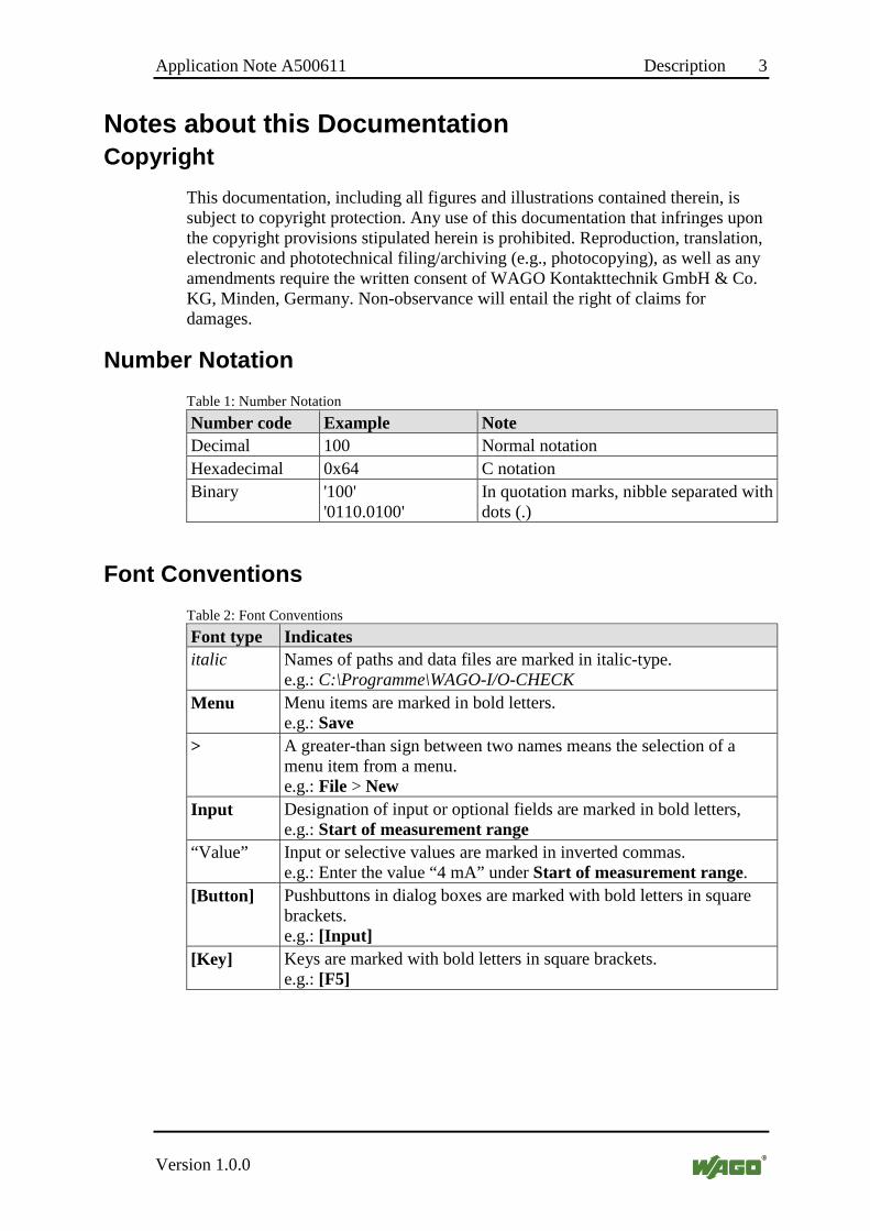
Number Notation
Table 1: Number Notation
Number code Example Note Decimal 100 Normal notation Hexadecimal 0x64 C notation Binary '100'
'0110.0100' In quotation marks, nibble separated with dots (.)
Font Conventions
Table 2: Font Conventions
Font type Indicates italic Names of paths and data files are marked in italic-type.
e.g.: C:\Programme\WAGO-I/O-CHECK Menu Menu items are marked in bold letters.
e.g.: Save > A greater-than sign between two names means the selection of a
menu item from a menu. e.g.: File > New
Input Designation of input or optional fields are marked in bold letters, e.g.: Start of measurement range
“Value” Input or selective values are marked in inverted commas. e.g.: Enter the value “4 mA” under Start of measurement range.
[Button] Pushbuttons in dialog boxes are marked with bold letters in square brackets. e.g.: [Input]
[Key] Keys are marked with bold letters in square brackets. e.g.: [F5]

4 Description Application Note A500611
Version 1.0.0
Symbols
Personal Injury! Indicates a high-risk, imminently hazardous situation which, if not avoided, will result in death or serious injury.
Personal Injury Caused by Electric Current! Indicates a high-risk, imminently hazardous situation which, if not avoided, will result in death or serious injury.
Personal Injury! Indicates a moderate-risk, potentially hazardous situation which, if not avoided, could result in death or serious injury.
Personal Injury! Indicates a low-risk, potentially hazardous situation which, if not avoided, may result in minor or moderate injury.
Damage to Property! Indicates a potentially hazardous situation which, if not avoided, may result in damage to property.
Damage to Property Caused by Electrostatic Discharge (ESD)! Indicates a potentially hazardous situation which, if not avoided, may result in damage to property.
Important Note! Indicates a potential malfunction which, if not avoided, however, will not result in damage to property.
Application Note A500611 Description 5
Version 1.0.0
Additional Information: Refers to additional information which is not an integral part of this documentation (e.g., the Internet).
Legal Bases Subject to Change
WAGO Kontakttechnik GmbH & Co. KG reserves the right to make any alterations or modifications that serve to increase the efficiency of technical progress. WAGO Kontakttechnik GmbH & Co. KG owns all rights arising from granting patents or from the legal protection of utility patents. Third-party products are always mentioned without any reference to patent rights. Thus, the existence of such rights cannot be excluded.
Personnel Qualification
The use of the product described in this document is exclusively geared to specialists having qualifications in PLC programming, electrical specialists or persons instructed by electrical specialists who are also familiar with the appropriate current standards.
Moreover, the persons cited here must also be familiar with all of the products cited in this document, along with the operating instructions. They must also be capable of correctly predicting any hazards which may not arise until the products are combined.
WAGO Kontakttechnik GmbH & Co. KG assumes no liability resulting from improper action and damage to WAGO products and third-party products due to non-observance of the information contained in this document.

6 Description Application Note A500611
Version 1.0.0
Limitation of Liability
This documentation describes the use of various hardware and software components in specific example applications. The components may represent products or parts of products from different manufacturers. The respective operating instructions from the manufacturers apply exclusively with regard to intended and safe use of the products. The manufacturers of the respective products are solely responsible for the contents of these instructions.
The sample applications described in this documentation represent concepts, that is, technically feasible application. Whether these concepts can actually be implemented depends on various boundary conditions. For example, different versions of the hardware or software components can require different handling than that described here. Therefore, the descriptions contained in this documentation do not form the basis for assertion of a certain product characteristic.
Responsibility for safe use of a specific software or hardware configuration lies with the party that produces or operates the configuration. This also applies when one of the concepts described in this document was used for implementation of the configuration.
WAGO Kontakttechnik GmbH & Co. KG is not liable for any actual implementation of the concepts.

Application Note A500611 Description 7
Version 1.0.0
Table of Contents
Table of Contents ................................................................................................... 7
1 Description .................................................................................................... 9
2 Used material ................................................................................................ 9 2.1 Devices ...................................................................................................... 9 2.2 Tools .......................................................................................................... 9
3 System configuration S7-300 ..................................................................... 10
4 System configuration S7-1500 ................................................................... 12
5 Function blocks .......................................................................................... 14 5.1 FbPower494Command ............................................................................ 14 5.2 FbPower494AC_Values .......................................................................... 19 5.3 FbPower494DC_Values .......................................................................... 22
5.4 FbPower494Harmonic_Values ............................................................... 25 5.5 FbPower494State .................................................................................... 29 5.6 FbPower494AC_MultiValues ................................................................. 31 5.7 FbPower494AC_General ........................................................................ 34
6 Example ...................................................................................................... 36 6.1 Example project ...................................................................................... 36
7 Appendix ..................................................................................................... 40 7.1 typ_750_494_State .................................................................................. 40 7.2 Values of Collection 7 (DC) ................................................................... 41
7.3 Values of Collection 9 (AC) ................................................................... 43 7.4 Measured Variable for Collection 20 to 22 (Harmonic Analysis) .......... 46 7.5 Enumeration Values for Collection 20 to 22 (Harmonic Analysis) ........ 46

8 Description Application Note A500611
Version 1.0.0

Application Note A500611 Description 9
Version 1.0.0
1 Description
This application note shows how to access the Wago 3-Phase Power measurement module in TIA.
The example project contains two PLC devices, one for a S7-300 and one for a S7-1500. The S7-1500 PLC supports optimized block access.
2 Used material
2.1 Devices
Provider Quantity Description Order number Version*
WAGO 1 Profibus DP/V1 Fieldbus Coupler
750-333 FW17
WAGO 1 Profinet IO advanced Fieldbus Coupler
750-375 FW05
WAGO 1 3-Phase Power measurement module
750-494
SIEMENS 1 CPU 315-2 PN/DP 6ES7 315-2EH14-0AB0
V3.2
SIEMENS 1 CPU 1511-1 PN 6ES7 511-1AK00-0AB0
V1.1
*this version was used for the creation of this application note.
2.2 Tools
Description Order number Version*
TIA Portal V13 SP1 Update 5
*this version was used for the creation of this application note.
10 System configuration S7-300 Application Note A500611
Version 1.0.0
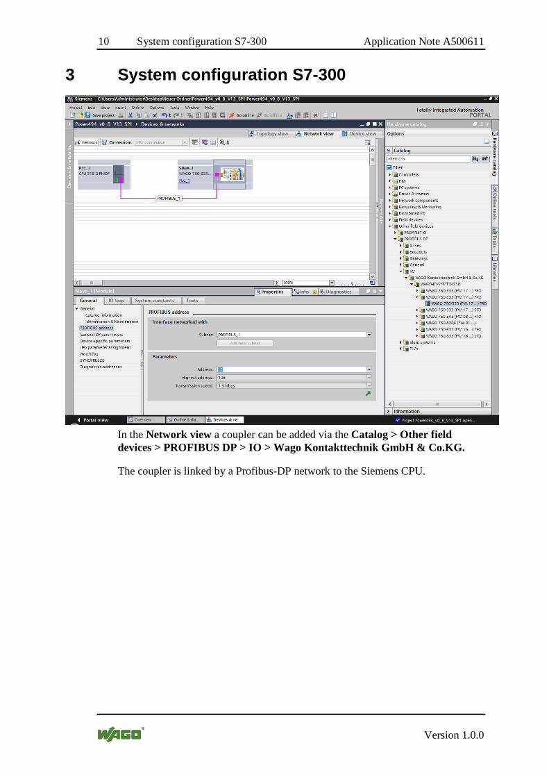
3 System configuration S7-300
In the Network view a coupler can be added via the Catalog > Other field devices > PROFIBUS DP > IO > Wago Kontakttechnik GmbH & Co.KG.
The coupler is linked by a Profibus-DP network to the Siemens CPU.

Application Note A500611 System configuration S7-300 11
Version 1.0.0
In the Device view of Slave_1, I/O-Modules can be added from the Catalog. To configure the module, select it out of the Device overview and go to Properties > Device-specific parameters.
Make sure the PROFIBUS address of the coupler is set properly.

12 System configuration S7-1500 Application Note A500611
Version 1.0.0
4 System configuration S7-1500
In the Network view a coupler can be added via the Catalog > Other field devices > PROFINET IO > IO > Wago Kontakttechnik GmbH & Co.KG.
The coupler and the PLC are linked by the PN/IE_1 Subnet.
Make sure the IP address of the coupler is set properly.

Application Note A500611 System configuration S7-1500 13
Version 1.0.0
In the Device view of wago-750-375, I/O-Modules can be added from the Catalog. To configure the module, select it out of the Device overview and go to Properties > Module parameters.

14 Function blocks Application Note A500611
Version 1.0.0
5 Function blocks
5.1 FbPower494Command
FbPower494Command
Category:
Name: FbPower494Command (>=V2.0)
Type: Function Function block X Program
Name of library:
Libraries used:
Applicable to: Input parameters Data type Comment: xEnable BOOL Enable operation xReadConfig BOOL Read configuration xWriteConfig BOOL Write configuration xExecuteCommand BOOL Execute command bCommand BYTE Commands according to manual
chapter commando interface 0x4->set factory default 0x37->preset counter …
dwPresetValueLow DWORD Preset value low dword according to commandos 0x37..0x45
dwPresetValueHigh DWORD Preset value high dword according to commandos 0x37..0x45
abIn_750_494 ARRAY [0..23] OF BYTE
Input array of 3-phase power measurement module 750-494.
Input/Output parameters Data type Comment: abOut_750_494 ARRAY [0..23]
OF BYTE Output array of 3-phase power measurement module 750-494.
typConfig_750_494 utConfig494 Configuration value bToken BYTE Control variable
Output parameter Data type Comment: xReady BOOL Read/write status of the settings
TRUE = Read/write operation disabled FALSE = Read/write operation enabled
xBusy BOOL Operation in progress

Application Note A500611 Function blocks 15
Version 1.0.0
FbPower494Command
bFeedback BYTE Function block status 0 = No error 1 = Read parameter 2 = Write parameter 3 = Error reading the parameters 4 = Error writing the parameters 5 = Executing command 6 = Error executing command 7 = Preset value exceeds valid range 255 = Timeout, no response from the module

16 Function blocks Application Note A500611
Version 1.0.0
FbPower494Command
Graphical illustration :
Application Note A500611 Function blocks 17
Version 1.0.0
FbPower494Command
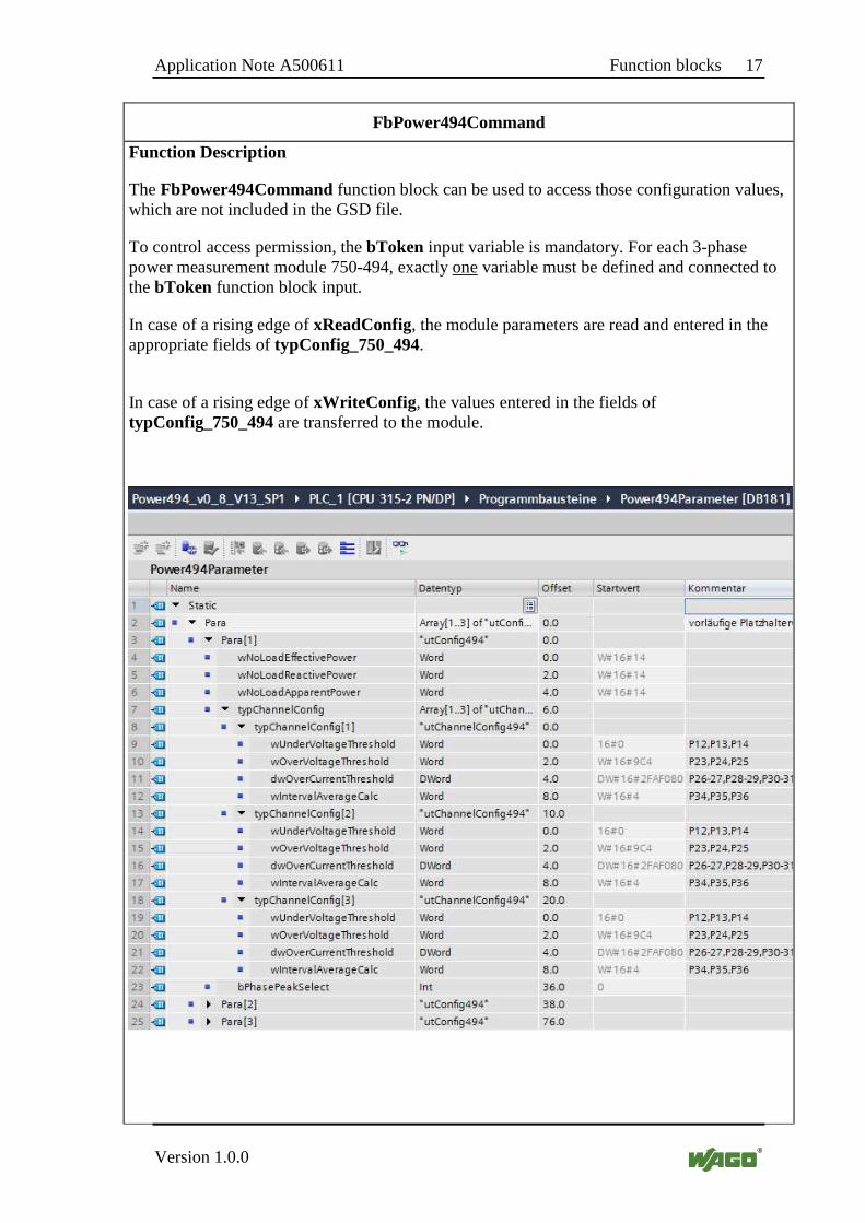
Function Description
The FbPower494Command function block can be used to access those configuration values, which are not included in the GSD file.
To control access permission, the bToken input variable is mandatory. For each 3-phase power measurement module 750-494, exactly one variable must be defined and connected to the bToken function block input.
In case of a rising edge of xReadConfig, the module parameters are read and entered in the appropriate fields of typConfig_750_494.
In case of a rising edge of xWriteConfig , the values entered in the fields of typConfig_750_494 are transferred to the module.
18 Function blocks Application Note A500611
Version 1.0.0
FbPower494Command
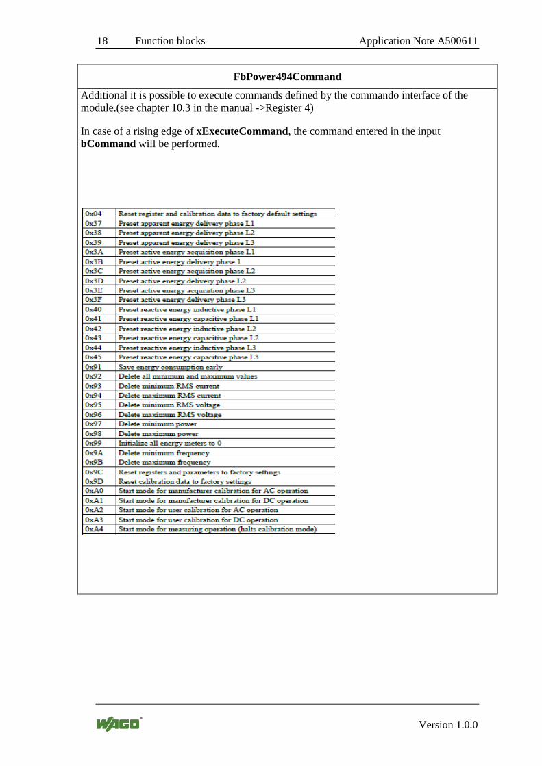
Additional it is possible to execute commands defined by the commando interface of the module.(see chapter 10.3 in the manual ->Register 4)
In case of a rising edge of xExecuteCommand, the command entered in the input bCommand will be performed.
Application Note A500611 Function blocks 19
Version 1.0.0
5.2 FbPower494AC_Values
FbPower494AC_Values
Category:
Name: FbPower494AC_Values Type: Function Function block X Program
Name of library:
Libraries used: Applicable to: Input parameters Data type Comment: xEnable BOOL Enable operation iAC_Values1 INT Selection of the measured value ID
of Collection 9. Value range and designations, see appendix.
iAC_Values2 INT iAC_Values3 INT iAC_Values4 INT abIn_750_494 ARRAY [0..23]
OF BYTE Input array of 3-phase power measurement module 750-494.
Input/Output parameters Data type Comment: abOut_750_494 ARRAY [0..23]
OF BYTE Output array of 3-phase power measurement module 750-494.
bToken BYTE Control variable for reading measured values.
Output parameter Data type Comment: xReady BOOL Read status of the measured values
TRUE = Read operation disabled FALSE = Read operation enabled
xBusy BOOL Access active bFeedback BYTE Function block status
0 = No error 1 = All entered measured value
IDs invalid 2 = Timeout, no response from the module 3 = Function block disabled …
rMeasuredValue1 REAL Scaled measured value for iAC_Values1 - iAC_Values4 rMeasuredValue2 REAL
rMeasuredValue3 REAL rMeasuredValue4 REAL

20 Function blocks Application Note A500611
Version 1.0.0
FbPower494AC_Values
Graphical illustration :
Application Note A500611 Function blocks 21
Version 1.0.0
FbPower494AC_Values
Function Description
The FbPower494AC_Values function block can be used for cyclic reading of up to four measured values of collection 9. It can be used multiple times in one project.
If the xEnable input is TRUE, the function block is enabled and a cyclic query is carried out.
To control access permission, the bToken input variable is mandatory. For each 3-phase power measurement module 750-494, exactly one variable must be defined and connected to the bToken function block input.
The abIn _750_494 and abOut_750_494 inputs contain the input or output array for data exchange with the 3-phase power measurement module.
The bFeedback output provides information about processing of the measured value query or the status of the function block and is valid if xReady is TRUE:
0 = The last measured value query has been completed successfully 1 = All entries iAC_Values1 – iAC_Values4 are outside the valid range (either 0 or greater than the maximum ID of the AC collection) 2 = Timeout, not all measured values have been reported back 3 = The function block is disabled (xEnable = FALSE) 4 = A parameter process is currently active, no measured value query 16 = Overflow measured value 1 32 = Overflow measured value 2 48 = Overflow measured value 1 + 2 64 = Overflow measured value 3 80 = Overflow measured value 1 + 3 96 = Overflow measured value 2 + 3 112 = Overflow measured value 1 + 2 + 3 128 = Overflow measured value 4 144 = Overflow measured value 1 + 4 160 = Overflow measured value 2 + 4 176 = Overflow measured value 1 + 2 + 4 192 = Overflow measured value 3 + 4 208 = Overflow measured value 1 + 3 + 4 224 = Overflow measured value 2 + 3 + 4 240 = Overflow measured value 1 + 2 + 3 + 4
The last read values are displayed at the rMeasuredValue1 – rMeasuredValue4 outputs. The measured values correspond to the IDs entered at the iAC_Values1 – iAC_Values4 inputs (see appendix).

22 Function blocks Application Note A500611
Version 1.0.0
5.3 FbPower494DC_Values
FbPower494DC_Values
Category:
Name: FbPower494DC_Values Type: Function Function block X Program
Name of library:
Libraries used: Applicable to: Input parameters Data type Comment: xEnable BOOL Enable operation iDC_Values1 INT Selection of the measured value ID
of Collection 7. Value range and designations, see appendix.
iDC_Values2 INT iDC_Values3 INT iDC_Values4 INT abIn_750_494 ARRAY [0..23]
OF BYTE Input array of 3-phase power measurement module 750-494.
Input/Output parameters Data type Comment: abOut_750_494 ARRAY [0..23]
OF BYTE Output array of 3-phase power measurement module 750-494.
bToken BYTE Control variable for reading measured values.
Output parameter Data type Comment: xReady BOOL Read status of the measured values
TRUE = Read operation disabled FALSE = Read operation enabled
xBusy BOOL Access active bFeedback BYTE Function block status
0 = No error 1 = All entered measured value
IDs invalid 2 = Timeout, no response from the module 3 = Function block disabled …
rMeasuredValue1 REAL Scaled measured value for iDC_Values1 - iDC_Values4 rMeasuredValue2 REAL
rMeasuredValue3 REAL rMeasuredValue4 REAL

Application Note A500611 Function blocks 23
Version 1.0.0
FbPower494DC_Values
Graphical illustration :

24 Function blocks Application Note A500611
Version 1.0.0
FbPower494DC_Values
Function Description
The FbPower494DC_Values function block can be used for cyclic reading of up to four measured values of collection 7. It can be used multiple times in one project.
If the xEnable input is TRUE, the function block is enabled and a cyclic query is carried out.
To control access permission, the bToken input variable is mandatory. For each 3-phase power measurement module 750-494, exactly one variable must be defined and connected to the bToken function block input.
The abIn _750_494 and abOut_750_494 inputs contain the input or output array for data exchange with the 3-phase power measurement module.
The bFeedback output provides information about processing of the measured value query or the status of the function block and is valid if xReady is TRUE:
0 = The last measured value query has been completed successfully 1 = All entries iDC_Values1 – iDC_Values4 are outside the valid range (either 0 or greater than the maximum ID of the DC collection) 2 = Timeout, not all measured values have been reported back 3 = The function block is disabled (xEnable = FALSE) 4 = A parameter process is currently active, no measured value query 16 = Overflow measured value 1 32 = Overflow measured value 2 48 = Overflow measured value 1 + 2 64 = Overflow measured value 3 80 = Overflow measured value 1 + 3 96 = Overflow measured value 2 + 3 112 = Overflow measured value 1 + 2 + 3 128 = Overflow measured value 4 144 = Overflow measured value 1 + 4 160 = Overflow measured value 2 + 4 176 = Overflow measured value 1 + 2 + 4 192 = Overflow measured value 3 + 4 208 = Overflow measured value 1 + 3 + 4 224 = Overflow measured value 2 + 3 + 4 240 = Overflow measured value 1 + 2 + 3 + 4
The measured values last read are displayed at the rMeasuredValue1 – rMeasuredValue4 outputs. The measured values correspond to the IDs entered at the iDC_Values1 –iDC_Values4 inputs (see appendix).

Application Note A500611 Function blocks 25
Version 1.0.0
5.4 FbPower494Harmonic_Values
FbPower494Harmonic_Values
Category:
Name: FbPower494Harmonic_Values Type: Function Function block X Program
Name of library:
Libraries used:
Applicable to: Input parameters Data type Comment: xEnable BOOL Enable operation bPhase BYTE Specification of the phase to be
measured. Default setting = 1
iHarmonic_Measurand INT 1..4
iHarmonic_Values1 INT 2..41, 100
iHarmonic_Values2 INT 2..41, 100 iHarmonic_Values3 INT 2..41,100 abIn_750_494 ARRAY [0..23]
OF BYTE Input array of 3-phase power measurement module 750-494.
Input/Output parameters Data type Comment: abOut_750_494 ARRAY [0..23]
OF BYTE Output array of 3-phase power measurement module 750-494.
bToken BYTE Control variable for reading measured values.
Output parameter Data type Comment: xReady BOOL Read status of the measured values
TRUE = Read operation disabled FALSE = Read operation enabled
bFeedback BYTE Function block status 0 = No error 1 = All entered value IDs invalid 2 = Timeout, no response from the module 3 = Function block disabled 4 = Parameter editing enabled (read/write)
rMeasuredHarmonic1 REAL Scaled measured value for iHarmonic_Values1 - iHarmonic_Values3
rMeasuredHarmonic2 REAL rMeasuredHarmonic3 REAL

26 Function blocks Application Note A500611
Version 1.0.0
FbPower494Harmonic_Values
Graphical illustration :
Application Note A500611 Function blocks 27
Version 1.0.0
FbPower494Harmonic_Values
Function Description
The FbPower494Harmonic_Values function block can be used for cyclic reading of up to three harmonics of the measured value collections 20 to 22. It can be used multiple times in one project.
If the xEnable input is TRUE, the function block is enabled and a cyclic query is carried out.
The phase is selected via the bPhase. input.
To control access permission, the bToken input variable is mandatory. For each 3-phase power measurement module 750-494, exactly one variable must be defined and connected to the bToken function block input.
The abIn _750_494 and abOut_750_494 inputs contain the input or output array for data exchange with the 3-phase power measurement module.
The iHarmonicMeasurand is used to determine the measured variable of the harmonics.
1 - RmsCurrent (RMS current) 2 - RmsVoltage (RMS voltage) 3 - HarmonicDistortion_Current (THD / HD current) 4 - HarmonicDistortion_Voltage (THD / HD voltage)
For the iHarmonic_Values1 – iHarmonic_Values3 inputs numerical values in the range of 2 to 41 and the value 100 are allowed. The value 100 is used to select the fundamental harmonic.
The bFeedback output provides information about processing of the measured value query or the status of the function block and is valid if xReady is TRUE:
0 =The last measured value query has been completed successfully 1 = All entries iHarmonic_Values1 – iHarmonic_Values3 are outside the valid range (either 0 or greater than the maximum ID of the collection) 2 = Timeout, not all measured values have been reported back 3 = The function block is disabled (xEnable = FALSE) 4 = A parameter process is currently active, no measured value query 16 = Overflow Value 1 32 = Overflow Value 2 48 = Overflow Value 1 + 2 64 = Overflow Value 3 80 = Overflow Value 1 + 3 96 = Overflow Value 2 + 3 112 = Overflow Value 1 + 2 + 3 128 = Overflow Value 4 144 = Overflow Value 1 + 4 160 = Overflow Value 2 + 4
28 Function blocks Application Note A500611
Version 1.0.0
FbPower494Harmonic_Values
176 = Overflow Value 1 + 2 + 4 192 = Overflow Value 3 + 4 208 = Overflow Value 1 + 3 + 4 224 = Overflow Value 2 + 3 + 4 240 = Overflow Value 1 + 2 + 3 + 4
The measured values last read are displayed at the rMeasuredHarmonic1 – rMeasuredHarmonic3 outputs. The measured values correspond to the ID entered at the iHarmonic_Values1 – iHarmonic_Values3 inputs (see appendix).

Application Note A500611 Function blocks 29
Version 1.0.0
5.5 FbPower494State
FbPower494State
Category:
Name: FbPower494State Type: Function Function block X Program
Name of library:
Libraries used:
Applicable to: Input parameters Data type Comment: xEnable BOOL Enable operation abIn_750_494 ARRAY [0..23]
OF BYTE Input array of 3-phase power measurement module 750-494.
Input/Output parameters Data type Comment: abOut_750_494 ARRAY [0..23]
OF BYTE Output array of 3-phase power measurement module 750-494.
Output parameter Data type Comment: xReady BOOL Read status of the FB
TRUE = Read operation disabled FALSE = Read operation enabled
typ_750_494_state ut49xState Status information
Graphical illustration :

30 Function blocks Application Note A500611
Version 1.0.0
FbPower494State
Function Description:
The Fb_750_494_State function block can be used to retrieve detailed information on the state of the 750-494 3-Phase Power Measurement Module.
The abIn _750_494 and abOut_750_494 inputs contain the input or output array for data exchange of the 3-Phase Power Measurement Module. The variables at these inputs must be linked to the corresponding hardware address. The address depends on the position at which the module is installed.
The typ_750_494_State output contains status information on the 750-494 3-Phase Power Measurement Module. (Appendix)
Application Note A500611 Function blocks 31
Version 1.0.0
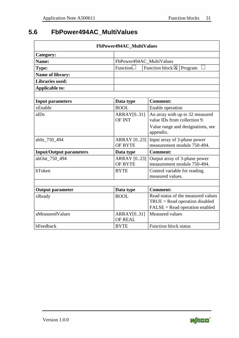
5.6 FbPower494AC_MultiValues
FbPower494AC_MultiValues
Category:
Name: FbPower494AC_MultiValues Type: Function Function block X Program
Name of library:
Libraries used:
Applicable to: Input parameters Data type Comment: xEnable BOOL Enable operation aIDs ARRAY[0..31]
OF INT An array with up to 32 measured value IDs from collection 9. Value range and designations, see appendix.
abIn_750_494 ARRAY [0..23] OF BYTE
Input array of 3-phase power measurement module 750-494.
Input/Output parameters Data type Comment: abOut_750_494 ARRAY [0..23]
OF BYTE Output array of 3-phase power measurement module 750-494.
bToken BYTE Control variable for reading measured values.
Output parameter Data type Comment: xReady BOOL Read status of the measured values
TRUE = Read operation disabled FALSE = Read operation enabled
aMeasuredValues ARRAY[0..31] OF REAL
Measured values
bFeedback BYTE Function block status
32 Function blocks Application Note A500611
Version 1.0.0
FbPower494AC_MultiValues
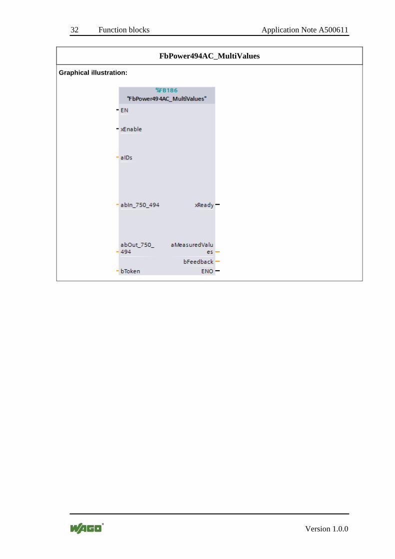
Graphical illustration:

Application Note A500611 Function blocks 33
Version 1.0.0
FbPower494AC_MultiValues
Function Description
The FbPower494AC_MultiValues function block can be used for cyclic reading of up to 32 measured values of collection 9. It can be used multiple times in one project.
If the xEnable input is TRUE, the function block is enabled and a cyclic query is carried out.
To control access permission, the bToken input variable is mandatory. For each 3-phase power measurement module 750-494, exactly one variable must be defined and connected to the bToken function block input.
The abIn _750_494 and abOut_750_494 inputs contain the input or output array for data exchange with the 3-phase power measurement module.
The bFeedback output provides information about processing of the measured value query or the status of the function block and is valid if xReady is TRUE:
0 = The last measured value query has been completed successfully 1 = All entries iAC_Values1 – iAC_Values4 are outside the valid range (either 0 or greater than the maximum ID of the AC collection) 2 = Timeout, not all measured values have been reported back 3 = The function block is disabled (xEnable = FALSE) 4 = A parameter process is currently active, no measured value query 16 = Overflow measured value 1 32 = Overflow measured value 2 48 = Overflow measured value 1 + 2 64 = Overflow measured value 3 80 = Overflow measured value 1 + 3 96 = Overflow measured value 2 + 3 112 = Overflow measured value 1 + 2 + 3 128 = Overflow measured value 4 144 = Overflow measured value 1 + 4 160 = Overflow measured value 2 + 4 176 = Overflow measured value 1 + 2 + 4 192 = Overflow measured value 3 + 4 208 = Overflow measured value 1 + 3 + 4 224 = Overflow measured value 2 + 3 + 4 240 = Overflow measured value 1 + 2 + 3 + 4
The read values are displayed at the aMeasuredValues output.

34 Function blocks Application Note A500611
Version 1.0.0
5.7 FbPower494AC_General
FbPower494AC_General
Category:
Name: FbPower494AC_General Type: Function Function block X Program
Name of library:
Libraries used:
Applicable to: Input parameters Data type Comment: xEnable BOOL Enable operation aIDs ARRAY[0..31]
OF INT An array with up to 32 measured value IDs from collection 9. Value range and designations, see appendix.
abIn_750_494 ARRAY [0..23] OF BYTE
Input array of 3-phase power measurement module 750-494.
Input/Output parameters Data type Comment: abOut_750_494 ARRAY [0..23]
OF BYTE Output array of 3-phase power measurement module 750-494.
bToken BYTE Control variable for reading measured values.
xDeleteMinMaxValue BOOL Delete all Min/Max values xDeleteEnergyCounter BOOL Delete all energy counter
Output parameter Data type Comment: xReady BOOL Read status of the measured values
TRUE = Read operation disabled FALSE = Read operation enabled
aMeasuredValues ARRAY[0..31] OF REAL
Measured values
xGeneralError BOOL General error (one or more errors occurred)
xModulError BOOL Group error for I/O module xPhase1Error BOOL Group error Phase L1 xPhase2Error BOOL Group error Phase L2 xPhase3Error BOOL Group error Phase L3

Application Note A500611 Function blocks 35
Version 1.0.0
FbPower494AC_General
Graphical illustration :
Function Description
The FbPower494AC_General function block can be used for cyclic reading of up to 32 measured values of collection 9. It can be used multiple times in one project.
If the xEnable input is TRUE, the function block is enabled and a cyclic query is carried out.
To control access permission, the bToken input variable is mandatory. For each 3-phase power measurement module 750-494, exactly one variable must be defined and connected to the bToken function block input.
The abIn _750_494 and abOut_750_494 inputs contain the input or output array for data exchange with the 3-phase power measurement module.
The in_out variables xDeleteMinMaxValues and xDeleteEnergyCounter allow to reset the appropriate values. The function block will reset the variables after the action is done.

36 Example Application Note A500611
Version 1.0.0
6 Example
6.1 Example project
DPRD_DAT and DPWR_DAT are used to read/write consistent data > 4 Byte of a DP slave.
On the CPU 1511-PN, LOG2MOD is used to to determine the hardware identifier for the IO (sub)module.
Application Note A500611 Example 37
Version 1.0.0
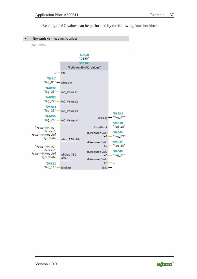
Reading of AC values can be performed by the following function block:
38 Example Application Note A500611
Version 1.0.0
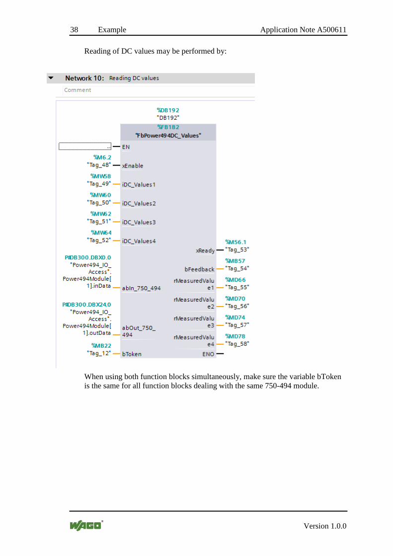
Reading of DC values may be performed by:
When using both function blocks simultaneously, make sure the variable bToken is the same for all function blocks dealing with the same 750-494 module.
Application Note A500611 Example 39
Version 1.0.0
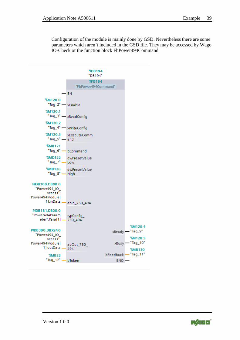
Configuration of the module is mainly done by GSD. Nevertheless there are some parameters which aren’t included in the GSD file. They may be accessed by Wago IO-Check or the function block FbPower494Command.
40 Appendix Application Note A500611
Version 1.0.0
7 Appendix
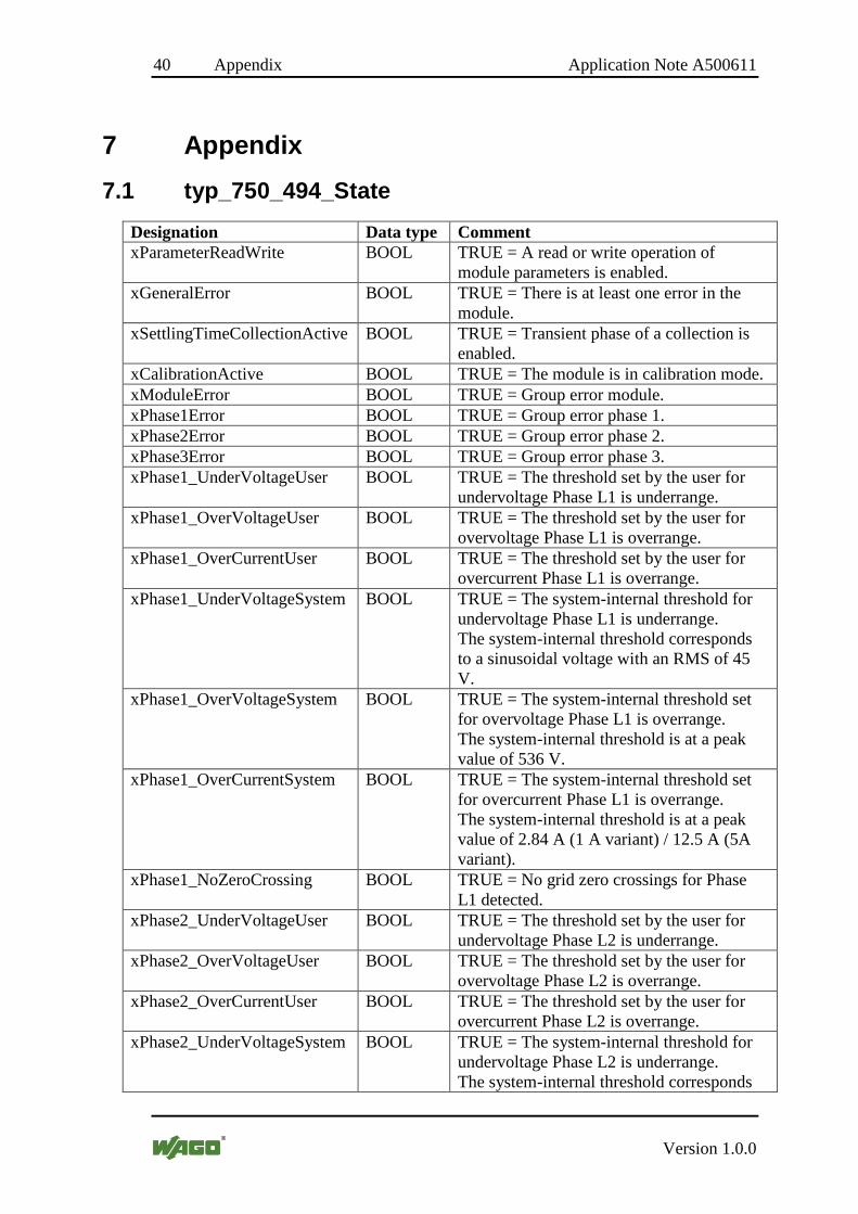
7.1 typ_750_494_State
Designation Data type Comment xParameterReadWrite BOOL TRUE = A read or write operation of
module parameters is enabled. xGeneralError BOOL TRUE = There is at least one error in the
module. xSettlingTimeCollectionActive BOOL TRUE = Transient phase of a collection is
enabled. xCalibrationActive BOOL TRUE = The module is in calibration mode. xModuleError BOOL TRUE = Group error module. xPhase1Error BOOL TRUE = Group error phase 1. xPhase2Error BOOL TRUE = Group error phase 2. xPhase3Error BOOL TRUE = Group error phase 3. xPhase1_UnderVoltageUser BOOL TRUE = The threshold set by the user for
undervoltage Phase L1 is underrange. xPhase1_OverVoltageUser BOOL TRUE = The threshold set by the user for
overvoltage Phase L1 is overrange. xPhase1_OverCurrentUser BOOL TRUE = The threshold set by the user for
overcurrent Phase L1 is overrange. xPhase1_UnderVoltageSystem BOOL TRUE = The system-internal threshold for
undervoltage Phase L1 is underrange. The system-internal threshold corresponds to a sinusoidal voltage with an RMS of 45 V.
xPhase1_OverVoltageSystem BOOL TRUE = The system-internal threshold set for overvoltage Phase L1 is overrange. The system-internal threshold is at a peak value of 536 V.
xPhase1_OverCurrentSystem BOOL TRUE = The system-internal threshold set for overcurrent Phase L1 is overrange. The system-internal threshold is at a peak value of 2.84 A (1 A variant) / 12.5 A (5A variant).
xPhase1_NoZeroCrossing BOOL TRUE = No grid zero crossings for Phase L1 detected.
xPhase2_UnderVoltageUser BOOL TRUE = The threshold set by the user for undervoltage Phase L2 is underrange.
xPhase2_OverVoltageUser BOOL TRUE = The threshold set by the user for overvoltage Phase L2 is overrange.
xPhase2_OverCurrentUser BOOL TRUE = The threshold set by the user for overcurrent Phase L2 is overrange.
xPhase2_UnderVoltageSystem BOOL TRUE = The system-internal threshold for undervoltage Phase L2 is underrange. The system-internal threshold corresponds
Application Note A500611 Appendix 41
Version 1.0.0
Designation Data type Comment to a sinusoidal voltage with an RMS of 45 V.
xPhase2_OverVoltageSystem BOOL TRUE = The system-internal threshold set for overvoltage Phase L2 is overrange. The system-internal threshold is at a peak value of 536 V.
xPhase2_OverCurrentSystem BOOL TRUE = The system-internal threshold set for overcurrent Phase L2 is overrange. The system-internal threshold is at a peak
xPhase2_NoZeroCrossing BOOL TRUE = No grid zero crossings for Phase L2 detected.
xPhase3_UnderVoltageUser BOOL TRUE = The threshold set by the user for undervoltage Phase L3 is underrange.
xPhase3_OverVoltageUser BOOL TRUE = The threshold set by the user for overvoltage Phase L3 is overrange.
xPhase3_OverCurrentUser BOOL TRUE = The threshold set by the user for overcurrent Phase L3 is overrange.
xPhase3_UnderVoltageSystem BOOL TRUE = The system-internal threshold for undervoltage Phase L3 is underrange. The system-internal threshold corresponds to a sinusoidal voltage with an RMS of 45 V.
xPhase3_OverVoltageSystem BOOL TRUE = The system-internal threshold set for overvoltage Phase L3 is overrange. The system-internal threshold is at a peak value of 536 V.
xPhase3_OverCurrentSystem BOOL TRUE = The system-internal threshold set for overcurrent Phase L3 is overrange. The system-internal threshold is at a peak value of 2.84 A (1 A variant) / 12.5 A (5A variant).
xPhase3_NoZeroCrossing BOOL TRUE = No grid zero crossings for Phase L3 detected.
xModule_RotatingField BOOL TRUE = The phasing does not correspond to the order L1-L2-L3.
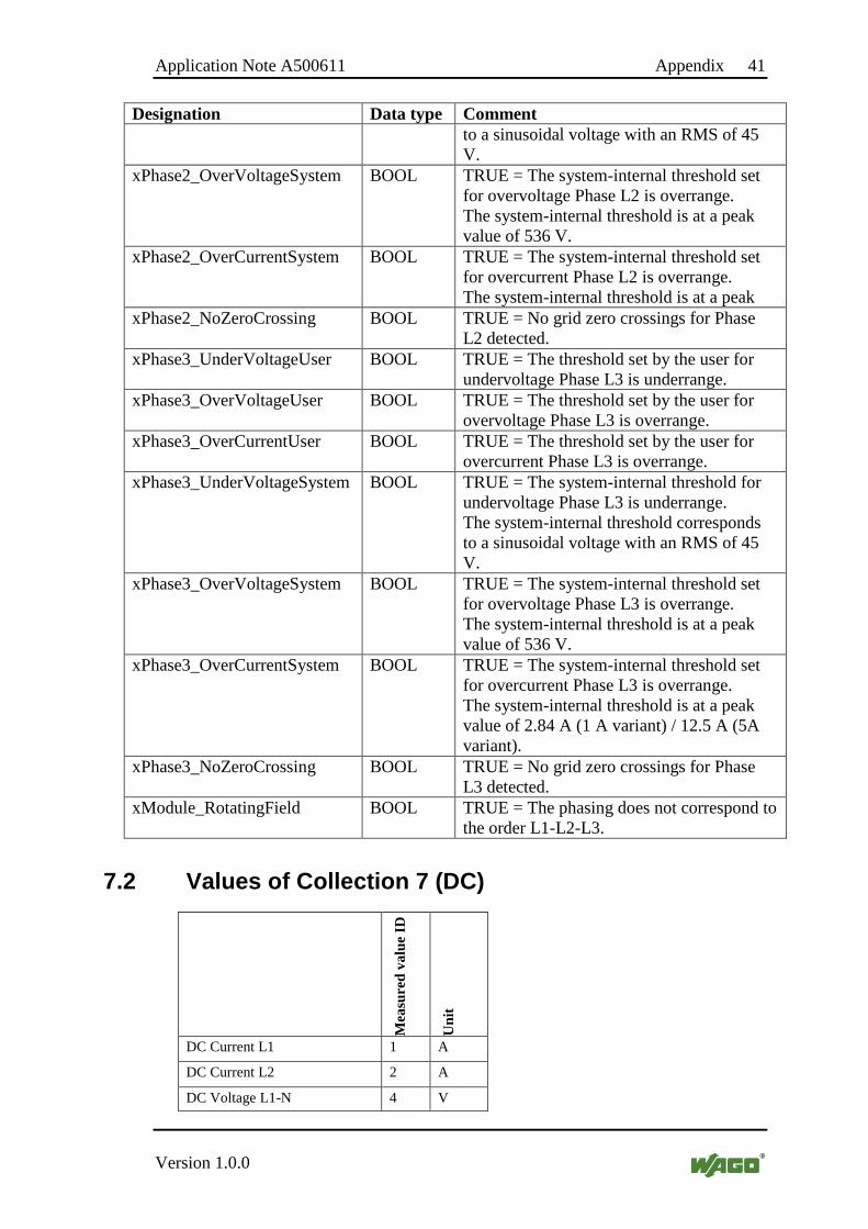
7.2 Values of Collection 7 (DC)
Mea
sure
d va
lue
ID
Uni
t
DC Current L1 1 A
DC Current L2 2 A
DC Voltage L1-N 4 V

42 Appendix Application Note A500611
Version 1.0.0
Mea
sure
d va
lue
ID
Uni
t
DC Voltage L2-N 5 V
Power L1 7 W
Power L2 8 W

Application Note A500611 Appendix 43
Version 1.0.0
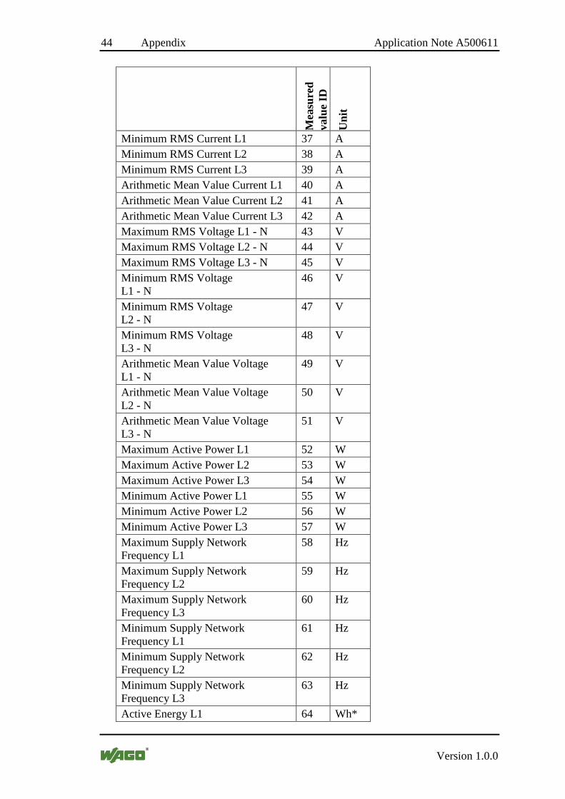
7.3 Values of Collection 9 (AC)
Mea
sure
d va
lue
ID
Uni
t
RMS Current L1 1 A RMS Current L2 2 A RMS Current L3 3 A RMS Voltage L1 - N 4 V RMS Voltage L2 - N 5 V RMS Voltage L3 - N 6 V Active Power L1 7 W Active Power L2 8 W Active Power L3 9 W Reactive Power L1 10 var Reactive Power L2 11 var Reactive Power L3 12 var Apparent Power L1 13 VA Apparent Power L2 14 VA Apparent Power L3 15 VA Supply Network Frequency L1 16 Hz Supply Network L2 17 Hz Supply Network L3 18 Hz Phase Angle phi L1 19 Deg Phase Angle phi L2 20 Deg Phase Angle phi L3 21 Deg Cos Phi L1 22 Cos Phi L2 23 Cos Phi L3 24 Power Factor PF L1 25 Power Factor PF L2 26 Power Factor PF L3 27 Power Factor LF L1 28 Power Factor LF L2 29 Power Factor LF L3 30 RMS Voltage L1 - L2 31 V RMS Voltage L1 - L3 32 V RMS Voltage L2 - L3 33 V Maximum RMS Current L1 34 A Maximum RMS Current L2 35 A Maximum RMS Current L3 36 A
44 Appendix Application Note A500611
Version 1.0.0
Mea
sure
d va
lue
ID
Uni
t
Minimum RMS Current L1 37 A Minimum RMS Current L2 38 A Minimum RMS Current L3 39 A Arithmetic Mean Value Current L1 40 A Arithmetic Mean Value Current L2 41 A Arithmetic Mean Value Current L3 42 A Maximum RMS Voltage L1 - N 43 V Maximum RMS Voltage L2 - N 44 V Maximum RMS Voltage L3 - N 45 V Minimum RMS Voltage L1 - N
46 V
Minimum RMS Voltage L2 - N
47 V
Minimum RMS Voltage L3 - N
48 V
Arithmetic Mean Value Voltage L1 - N
49 V
Arithmetic Mean Value Voltage L2 - N
50 V
Arithmetic Mean Value Voltage L3 - N
51 V
Maximum Active Power L1 52 W Maximum Active Power L2 53 W Maximum Active Power L3 54 W Minimum Active Power L1 55 W Minimum Active Power L2 56 W Minimum Active Power L3 57 W Maximum Supply Network Frequency L1
58 Hz
Maximum Supply Network Frequency L2
59 Hz
Maximum Supply Network Frequency L3
60 Hz
Minimum Supply Network Frequency L1
61 Hz
Minimum Supply Network Frequency L2
62 Hz
Minimum Supply Network Frequency L3
63 Hz
Active Energy L1 64 Wh*
Application Note A500611 Appendix 45
Version 1.0.0
Mea
sure
d va
lue
ID
Uni
t
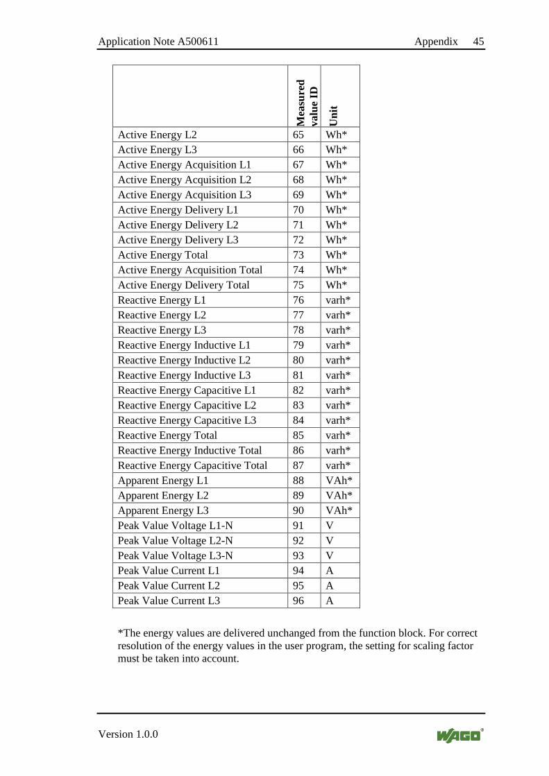
Active Energy L2 65 Wh* Active Energy L3 66 Wh* Active Energy Acquisition L1 67 Wh* Active Energy Acquisition L2 68 Wh* Active Energy Acquisition L3 69 Wh* Active Energy Delivery L1 70 Wh* Active Energy Delivery L2 71 Wh* Active Energy Delivery L3 72 Wh* Active Energy Total 73 Wh* Active Energy Acquisition Total 74 Wh* Active Energy Delivery Total 75 Wh* Reactive Energy L1 76 varh* Reactive Energy L2 77 varh* Reactive Energy L3 78 varh* Reactive Energy Inductive L1 79 varh* Reactive Energy Inductive L2 80 varh* Reactive Energy Inductive L3 81 varh* Reactive Energy Capacitive L1 82 varh* Reactive Energy Capacitive L2 83 varh* Reactive Energy Capacitive L3 84 varh* Reactive Energy Total 85 varh* Reactive Energy Inductive Total 86 varh* Reactive Energy Capacitive Total 87 varh* Apparent Energy L1 88 VAh* Apparent Energy L2 89 VAh* Apparent Energy L3 90 VAh* Peak Value Voltage L1-N 91 V Peak Value Voltage L2-N 92 V Peak Value Voltage L3-N 93 V Peak Value Current L1 94 A Peak Value Current L2 95 A Peak Value Current L3 96 A
*The energy values are delivered unchanged from the function block. For correct resolution of the energy values in the user program, the setting for scaling factor must be taken into account.
46 Appendix Application Note A500611
Version 1.0.0
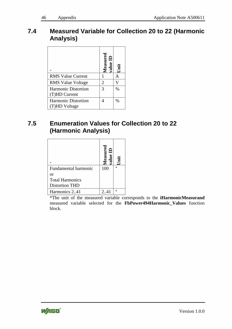
7.4 Measured Variable for Collection 20 to 22 (Harmonic Analysis)
- Mea
sure
d va
lue
ID
Uni
t
RMS Value Current 1 A RMS Value Voltage 2 V Harmonic Distortion (T)HD Current
3 %
Harmonic Distortion (T)HD Voltage
4 %
7.5 Enumeration Values for Collection 20 to 22 (Harmonic Analysis)
- Mea
sure
d va
lue
ID
Uni
t
Fundamental harmonic or Total Harmonics Distortion THD
100 *
Harmonics 2..41 2..41 *
*The unit of the measured variable corresponds to the iHarmonicMeasurand measured variable selected for the FbPower494Harmonic_Values function block.

WAGO Kontakttechnik GmbH & Co. KG Postfach 2880 • D-32385 Minden Hansastraße 27 • D-32423 Minden Telefon: +49 (0) 571/8 87 – 0 Telefax: +49 (0) 571/8 87 – 1 69 E-Mail: [email protected] Internet: http://www.wago.com