a.1a38 10 implementing thestudy airforce of sit right
TRANSCRIPT

A.1A38 10 IMPLEMENTING PC (LNEAR PREDICTIVE COOING) ALGORITHMS lTHESTUDY OF SP,.U AIRFORCE INST OF TECH
SIT RIGHT-PATTERSON AFB OH SCHOOL OF ENGI. C E MCKOWN
mNLSE Eh3AI/EE hE8D-4hh 9/hE
ELEMEh~hE

g 132 2
NANLBi ~ A AO~ll A
ACb
DIC
IEPREMENTING LPC ALG ORTHMS
AIN THRE ISTIUDY O PEHERCESSNGLG
Di2LTuio UnSiite
DTIC

AFIT/GE/EE/83D-4 5
Accession For
NTIS(AIDTIC TABUnannovuneed
JUStificntio.n
By
Distribution/
Availability Codes
Avail and/or
Dist Special
D?,c
II
IMPLEMENTING LPC ALGORITHMSIN THE STUDY OF SPEECH PROCESSING
THESIS
AFIT/GE/EE/8 3D-4 5
CRAIG E. McKOWN2LT USAF
DTICI I ELE2CTL.
SEB 2 2 184j
D
As-4k
. Approved for public release; distribution unlimited
WO-

AFIT/GE/EE/83D-45
IMPLEMENTING LPC ALGORITHMS IN THE STUDY OF SPEECH
PROCESSING
THESIS
Presented to the Faculty of the School of Engineering
of the Air Force Institute of Technology,
Air University
*in Partial Fulfillment of the
Requirements for the Degree of
Master of Science in Electrical Engineering
by
Craig E. McKown
2Lt USAF
Graduate Electrical Engineering
December 1983
4A
, Approved for public release; distribution unlimited
PREFACE
Digital Voice Communication is a pervasive phenomenon
in our society. Without even noticing it we carry on phone
conversations over a digital channel. So, why is digital
communication so widely used? One reason is that the
digital speech signals can be made more noise immune or even
secure than the analog signals. Another reason is the
advanced development in integrated circuit technology, which
allows easier implementation of digital processing
techniques. Whatever the case, the field of digital
communication is an exciting field and one which I feel is
expanding. Therefore, I am glad that I could prepare my
thesis under this topic.
Linear Predictive Coding is one facet of the field of
digital communication. The goal of the coding is to reduce
the bit rate of the signal sent over the communication
channel. The system I developed does not reduce the bit
rate very much, but then it is not a true communication
system. It is a computer simulation of such a system, which
will give the user an opportunity to explore some of the
ideas, methods, and problems of LPC.
Since the system developed here is a tool, the most
important product of the thesis may well be the user's
guide. It presentq the programs and demonstrates how a
student may actually process speech through an LPC system.
ii

But let me not forget those who made it possible for me
to finish this project and receive my degree. I must thank
my thesis advisor, Major Larry Kizer, who presented me with
the project and let me develop it in my own way.
I wish to thank my readers, Dr. Matthew Kabrisky and
Major Kenneth Castor. I also thank Dan Zambon for keeping
Bertha, the computer operating most of the time.
I also need to thank Capt Willis Janssen for tolerating
me those late nights in the summer when we hacked away until
midnight trying to debug code.
I am also indebted to my roommate, Chuck Lutes, who let
me use his computer to write this thesis.
Craig E. McKown
4gW
~iii
TABLE of CONTENTS
PAGE
Preface Bn ...... ................................. ...... ii
Table of Contents.............................iv
List of Figuress................. .. ............ . ....... vi
List of Tables ......... d............................ vii
ArAbstract ................. o........ ............ ... ...... viii
I Introduction Meth.................. ....... . I-8
Background ............. ....................... 11-9Statement of the Problem ...................... I-4Scope ... .. . . . . . . . . . . . . . . . . . -
Derviptio of the LPCte .........er.............II-5
ID. The Theory of Linear Prediction .............. II-
Autocorrelation Method ....................... 11-7Covariance method ............................ V1-8Solution Algorithms ... ................. . ... IV-9Summary .................... o ................. 1 -12
III. Development of the LPC System .......... III-
Description of the LPC Analyzer ............. 111-5Description of the Synthesizer ............. III-10Synchronous Analysis ......... e.... ......... 111-12Time Contraints ...... *...................... 111-15Summary* ......... . . .. . . .. . . . ... 111II -16
IV. Testing and Results......... ................ ... IV-4
The System ..... ...... .*Iooise ........-
V. Conclusions and Recommendations .................. V-1
C onc lus ions ...... V-Recommendations.......:.:.::::: .:.::: ,: ...:::::::::
Further Work in Software Development....... ... *V-3Further Testing ................ ... 9..........V-4
iv
CONTENTS!Page
* ~Appendix A: User's manual ...... .. . . . . . . . . . .. .... e.A-l
Appendix B: Program Listings.,.., . . . . ..............
Appendix C: Waveshapes of the Speech Signals ..... ....C-l
Appendix D: Code for the Subroutine LATTICE.o.oooooo.D-l
* I
tV.1 __
i- - - .
List of Figures
Figure Page
1-1 A model for the production of speech....#*......s..I-3
2-1 Cross section ofthe vocal tract....... #....*....I1-2
2-2 Schematic representation of the vocal tract ..... 11-2
3-1 Block diagram of the Analysis program ..........I111-2
3-2 Block diagram of the Synthesis program .........I111-3
*3-3 Pitch analysis frames ..................... 11-
3-4 Predictor coefficient analysis frames ......... iI-13
4-1 Formant Trajectory (four poles) ..... *........... IV-6
4-2 Formant Trajectory (six poles) .......... *....I6
4-3 Formant Trajectory (eight poles) ................ IV-7
4-4 Formant Trajectory (ten poles) ........... s...... IV-7
4-5 Formant Trajectory (twelve poles) ............... IV-8
4-6 Formant Trajectory (no noise) ............0...... IV-ll
4-7 Formant Trajectory (no noise) .................. IV-11
4-8 Formant Trajectory (SNR-l6dB) ................*..IV-12
4-9 Formant Trajectory (SNR-l4dB) ...........*.......IV-12
4-10 Formant Trajectory (SNR-8dB)..*............. .. IV-13
4-li Formant Trajectory (SNR-4dB).*..............IV-13
A vi

List of Tables
Table
4-1 Ranges of the Decision Variables .............. IV-3
4-2 Noise .......................................... IV-9
vii
k _____
77 -~ -,: "
ABSTRACT
This report describes a system which processes speech
using linear predictive methods. The system is a software
simulation of an LPC analyzer and synthesizer. The system
consists of two programs, one of which processes the speech
to generate the LPC parameters, and another which processes
these parameters to resynthesize the speech. An important
aspect of the system is that it enables the user to select
from various pitch and coefficient analysis methods. It
also allows the user to vary other parameters in order to
simulate other changes in the processing scheme.
To test the operation of the system, a regimen of
testing was performed by varying the different parameters.
A separate program allows a simple method for changing all
of the parameters over which the user has control. These
parameters are called the decision variables and each has an
allowable range of values. The system operated
satisfactorally over all values of the decision variables.
The flexibilty exhibited by the system in this testing
indicates that the system can be a valuable tool for the
study of linear predictive coding of speech in the Signal
Processing Laboratory at the Air Force Institute of
Technology.
viii - *

CHAPTER I
Introduction
Background
Communication, and in particular, digital voice
communication, is of vital concern to the U.S. Department of
Defense. This concern is founded in the rc ivement of the
military to maintain command and con ! over great
distances. This is especially apparent I the need for
aircraft to maintain contact with forces L che ground. A
problem arises, though, when many aircraft need to maintain
contact with the same command center. Since only a finite
number of radio frequencies (channels) are available, a
method of maintaining unambiguous communication is needed.
One method of resolving this is time division multiple
access, in which each aircraft is allocated a certain amount
of time to access the communication channel. The
communication system is arranged so that each communicator
tranmits and receives only during its allocated time slot.
Another method of sharing the channel is frequency division
multiplexing, in which each aircraft is allocated a separate
portion of the radio spectrum available in the communicaton
channel. In either method, the number of users of each
channel is limited by both the available bandwidth of the
channel and the bandwidths of the users. The bandwidth of
the channel is determined by the nature of the channel, the
1-1

geometry and physical realization. The bandwidth of the
users is a function of the bit rate of the message to be
transmitted, as the bit rate of the messages increases, the
bandwidth increases. One way to allow for more users is to
reduce the bit rate of each user. Linear Predictive Coding
(LPC) offers a means of reducing the bit rate of each user
when the message is voice communication.
The standard method of digital voice communication is
pulse code modulation (PCM), in which the analog voice
signal, or waveform, is sampled and quantized. Nyquist's
sampling theorem assures us that the sampling rate must be
twice that of the highest frequency in the original baseband
signal. High quality speech requires frequency components of
up to 3000 Hz [Ref 12], so after filtering, sampling is
often performed at 8000 Hz. Digitization of the sampled
speech is often performed by quantizing at 12 bits per
sample, a rate which has proven to enable high quality
speech reproduction. Such a system would require a
transmission rate of 96 kb/s. Various methods of waveform
coders are capable of producing high quality speech, but
only at rates above about 16 kb/s [Ref 1].
Linear Predictive Coding (LPC) is a method of digital
speech processing which reduces the required bandwidth of
the signal by reducing the bit rate required for
intelligible communication. Waveform coders, such as PCM,
transmit the waveshape of the signal, whereas LPC makes no
attempt to maintain the waveshape of the speech signal.
1-2
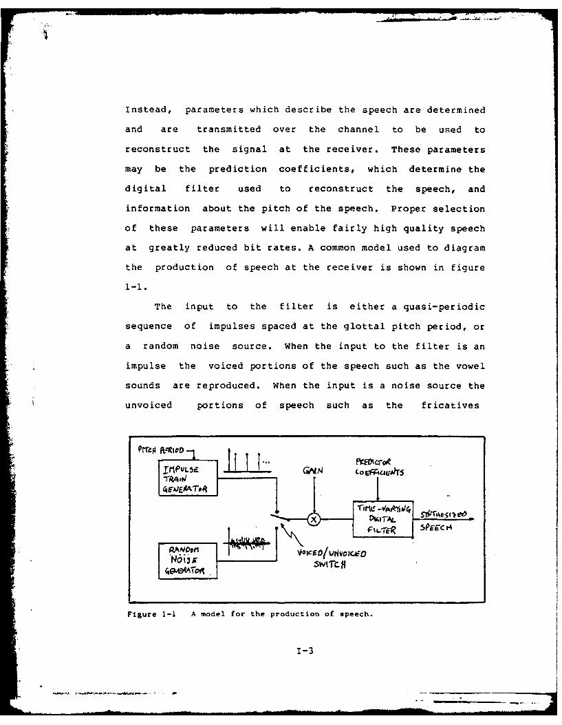
Instead, parameters which describe the speech are determined
and are transmitted over the channel to be used to
reconstruct the signal at the receiver. These parameters
may be the prediction coefficients, which determine the
digital filter used to reconstruct the speech, and
information about the pitch of the speech. Proper selection
of these parameters will enable fairly high quality speech
at greatly reduced bit rates. A common model used to diagram
the production of speech at the receiver is shown in figure
1-i.
The input to the filter is either a quasi-periodic
sequence of impulses spaced at the glottal pitch period, or
a random noise source. When the input to the filter is an
impulse the voiced portions of the speech such as the vowel
sounds are reproduced. When the input is a noise source the
unvoiced portions of speech such as the fricatives
v1Ati SWI-AL S T C cI-k
No VOICED1UNVO;x&Fo
Figure 1-1 A model for the production of speech.
1-3
I
(s,sh,f,th) are reproduced. The gain and coefficients of
the filter are determined by linear predictive analysis.
Statement of the Problem
The importance of LPC is indicated by the existence of
an Air Force standard for LPC (LPC-10). As LPC becomes
more prevalent a need exists for a system available at the
Air Force Institute of Technology which can demonstrate some
of the features and operations of LPC. Most implementatons
of LPC are in hardware, with most of the system hidden
within a "black box." These factors led to the need for the
development of a software model which would offer a better
opportunity to examine the system.
A number of algorithms exist which can be used to
determine the filter coefficients. Among these are the
autocorrelation and the covariance method. Also available
are a number of methods of pitch detection and extraction. A
software simulation is needed which would incorporate these
various algorithms and methods into a single, flexible
model. This model could be used as a learning device and as
a tool for further study of LPC. It would allow the student
or researcher an easy means to investigate the software of
the system and vary the algorithms used, consider changes of
the algorithm parameters and examine intermediate results.
It would also provide a means of addressing some of the
problems confronting LPC, in particular, the noise problem.
1-4
'II
Scope
The system presented in this thesis is designed
especially for the Signal Processing Laboratory at AFIT,
where it can operate as a useful tool for the study of the
general LPC method of coding speech. It is strictly
software; the code is written in FORTRAN5, developed on and
accesible from the Data General Eclipse S/250 computer in
the laboratory. It uses existing hardware and software for
the audio interface. It is meant to be easily used, easily
understood, and user friendly. It should be easy to update,
expand, or modify. It was designed to run as close to real
time as the constraints of the laboratory would permit.
Overview of the System
The system is divided into two main programs, an
analysis program and a synthesis program. This format was
chosen as it best simulates the tranmitter and reciever
nature of the LPC speech communication system. The inputs
to the analysis program are digitized speech and the
necessary decision variables (these will be explained
later). The outputs of this program are the LPC parameters.
The synthesizer uses these parameters to reproduce the
speech.
The flexibilty of the system is afforded by the
extensive use of subroutines. The system inputs the speech
in time segments, called frames, and operates on these
1-5
segments sequentially. This is a recurring process, and
most of the calculations are performed on each frame. The
subroutine structure allows easy access to the routines
which perform certain portions of the calculations, such as
pitch detection, coefficient generation, and other
systematically used operations. For instance, the
subroutines which perform coefficient generation are grouped
together, yet only one subroutine is used (although it is
used on each frame) during the execution of the program.
The other subroutines are retained for the case where
another method of coefficient generation is required. The
use of subroutines makes it easy to expand the system by
adding new routines which offer different methods of
performing the required calculations.
The LPC analyzer is the heart of the system. Most of
the decision variables affect the operation of the analyzer,
because they determine which subroutines will be used to
produce the necessary parameters for transmission. It reads
digitized (PCM) speech from a contiguous file of integer
values. It scales the incident speech if necessary, places
it in a floating point form, and writes it to an array. The
parameters (pitch information, predictor coefficients, and
energy) are calculated for each frame and then written to a
sequential file which is the input to the synthesis program.
This file acts as a communication channel between
transmitter and receiver and is referred to as the channel
file. Before any speech is processed, key parameters which
1-6
-A
are needed by the synthesizer are written to the channel
file. These parameters are needed by the synthesizer so
that it can correctly match its decoding and synthesis
scheme to a form compatible with that of the analyzer. If
the forms do not match, the LPC parameters will be read
incorrectly and speech will be impossible to reproduce.
The synthesizer reads the information from the channel
file and processes it to create intelligible speech. It
reads the pitch data and the length of the speech to be
proccessed. It then generates either pseudorandom noise or
a pulse train, which it writes to a array. This array is
the input to the digital filter which is described by the
prediction coefficients read from the channel. The output
*of this filter is written to a contiguous file and the
system then processes the next block of information. After
the entire channel file has been read, the output speech is
scaled so that it may be listened to with the use of the
"Audiohist' or the "Audiomod* program prepared by a previous
student [Ref 3] and available as a utility program on the
system in the Signal Processing Laboratory.
1-7
4
CHAPTER II
The Theory of Linear Prediction
Linear prediction is a method of analyzing a speech
waveform so that the complete waveform need not be
transmitted over a communication channel. A linear
prediction system takes a digital speech signal and
processes it so that only the "essence" of the signal
remains; no attempt is made to maintain the waveshape of the
signal. For our purpose, the essence of the signal is a
parametric model of the signal, where these parameters can
be used to reconstruct the signal. The linear prediction
system consists of two major operations or processes. One
process analyzes the incoming speech and extracts the
relevant parameters and transmits these over a communication
channel. Another process at the receiving end of the
channel transforms these parameters into speech. This
transformation is based on a time-varying digital filter
with predictor coefficients which model the vocal tract of
the speaker (see figures 2-1 and 2-2). Since the vocal
tract changes shape slowly it can be considered fixed over a
time interval on the order of 10 ms, and the digital filter
can characterize the vocal tract over this short interval
[Ref 12]. The input to this filter is the assumed
excitation of the actual human vocal tract: glottal pulses
occurring every pitch period, or random noise.
hI-i

VELVM NASAL
CVOAL
CORD5AIR FROtI LIJJ5
Fiqure 2-1 Cross section of the vocal tract showing the majoranatomical structures involved in speech production.
FRJIII ii VOCAL TRACT LUP5
VOCAL VARIABLECOR95 SHtAPE
Figure 2-2 Schematic representation of the vocal tractv
11-2

The question addressed by linear prediction is: how do we
find these predictor coefficients?
Speech, of course, is an analog process, so it must be
digitized before it can be processed by linear prediction
methods. This is usually accomplished by pulse code
modulation (PCM) in which the analog signal is quantized in
time (sampled) with a sampling frequency of fs' and
quantized in amplitude. For the analog waveform, s(t), the
sampled waveform can be expressed as
s(nT) = s(t)t=nT (2-1)
where T is the time between samples (T=l/fs). Since fs, and
therefore T remain constant (in our case f. Z 8000Hz), we
can write s(nT) as s(n) with no loss of generality.
If we assume that the signal, s(n), is the output of a
system (our assumption above concerning speech at the
receiver being the output of a filter allows this) with
input u(n), then that signal can be expressed as a linear
function of the past outputs and the present and past
inputs. That is, the output can be predicted by a linear
combination of inputs and outputs. Hence the description of
this scheme as linear prediction. This relation is written
as
p
s(n) - Zaksn-k) + GZbmu (n-m) ,bo 1 (2-2)
k-l m=O
where ak ,l < k < p, bm ,l < m < q and G are the
11-3
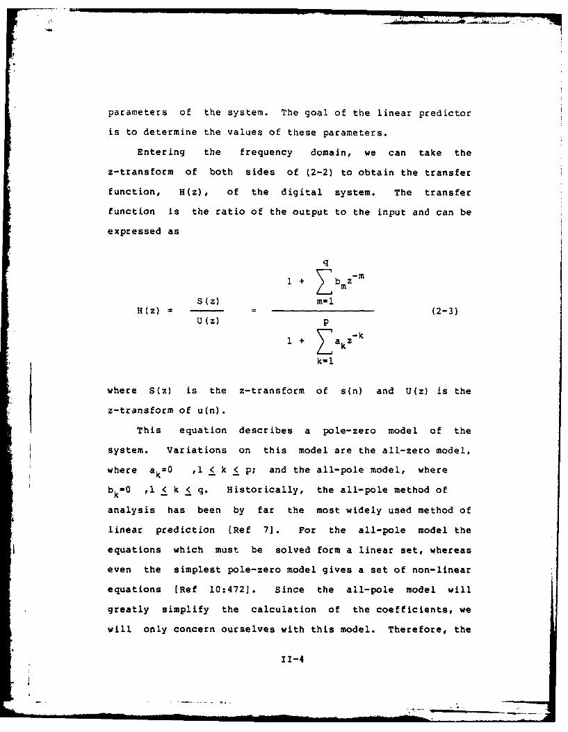
parameters of the system. The goal of the linear predictor
is to determine the values of these parameters.
Entering the frequency domain, we can take the
z-transform of both sides of (2-2) to obtain the transfer
function, H(z), of the digital system. The transfer
function is the ratio of the output to the input and can be
expressed as
q
1 + Z b z -m
S(z) m=lH(z) = = (2-3)
U(z) p
1 + Z akzk
k=1
where S(z) is the z-transform of s(n) and U(z) is the
z-transform of u(n).
This equation describes a pole-zero model of the
system. Variations on this model are the all-zero model,
where ak=0 ,l < k < p; and the all-pole model, where
bk= , 1< k < q. Historically, the all-pole method of
analysis has been by far the most widely used method of
linear prediction [Ref 71. For the all-pole model the
equations which must be solved form a linear set, whereas
even the simplest pole-zero model gives a set of non-linear
equations [Ref 10:472]. Since the all-pole model will
greatly simplify the calculation of the coefficients, we
will only concern ourselves with this model. Therefore, the
11-4

transfer function of interest is
G GH(z) = (2-4)
A(z) p
1 + T akz- k
k=l
A(z) will be referred to as the inverse filter, and the
coefficients ak , 1 < k < p will be referred to as the
predictor coefficients.
By taking an inverse z-transform, we return to the time
domain and get the relation
p
s(n) a - aks(n-k) + G u(n) (2-5)
kl
From this equation it is clearly evident that the output
sequence, s(n), can be generated with only one input, u(n)
and p previous outputs.
If we assume that the input u(n) is unknown [Ref 71, we
can calculate a prediction of s(n), ^(n) which is based
strictly on ther past outputs. This assumption gives us a
result which is independent of the input and can be written
as
p
s(n)- - aks(n-k) (2-6)
k-l
Now we will define the predictor error, e(n), as the
difference between the original signal, s(n), and the
II-5
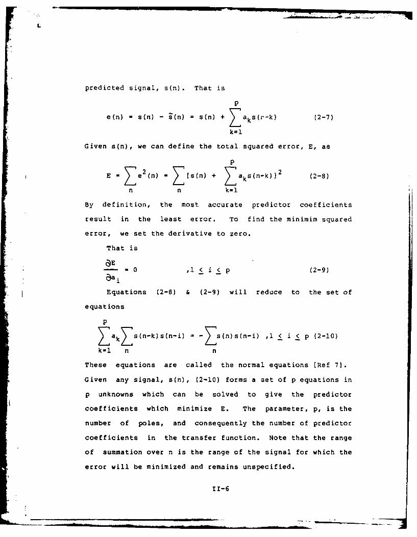
predicted signal, s(n). That is
p
e(n) = s(n) - 9(n) = s(n) + T aks(r-k) (2-7)
k-i
Given s(n), we can define the total squared error, E, as
p
E e e2 (n) = Z[s(n) + Zaks(n-k)]2 (2-8)
n n k=l
By definition, the most accurate predictor coefficients
result in the least error. To find the minimim squared
error, we set the derivative to zero.
That is
aE--- =0 ,i < i < p (2-9)
Equations (2-8) & (2-9) will reduce to the set of
equations
p
ZakZ s(n-k)s(n-i)= -Zs(n)s(n-i) 1 < i < p (2-10)
k-1 n n
These equations are called the normal equations [Ref 7].
Given any signal, s(n), (2-10) forms a set of p equations in
p unknowns which can be solved to give the predictor
coefficients which minimize E. The parameter, p, is the
number of poles, and consequently the number of predictor
coefficients in the transfer function. Note that the range
of summation over n is the range of the signal for which the
error will be minimized and remains unspecified.
11-6

Autocorrelation Method
If we let the range of summation over n be from -co to
+0 , we will get a global minimization of the error and
equation (2-10) reduces to
p
1 i _Za kR(i-k - -R(i) 1 < ( p (2-11)k=l
where R(i) is the autocorrelation, and is defined as
0O
R(i) = Zs(n) s(n-i) (2-12)
n=-CO
Since the signal is known over only a finite duration, we
divide the signal into frames and assume that the signal
s(n) is identically zero outside of the interval 0 < n <
N-1. A suitable way to express this is as
s(n) = s(n+N) w(n) (2-13)
where w(n) is a window function which is identically zero
outside of the interval 0 < n < N-I. This windowing process
produces frames which are N samples wide. Since excessive
errors will be encountered at the frame boundaries because
of our drastic assumption of zero outside of the frame, we
need to taper the edges of the window to zero. To
accomplish this we use a Hamming window. For simplicity of
notation we will drop the index N and the caret and speak
only of the signal s(n) which is properly only a portion
(one frame) of the complete signal.
11-7
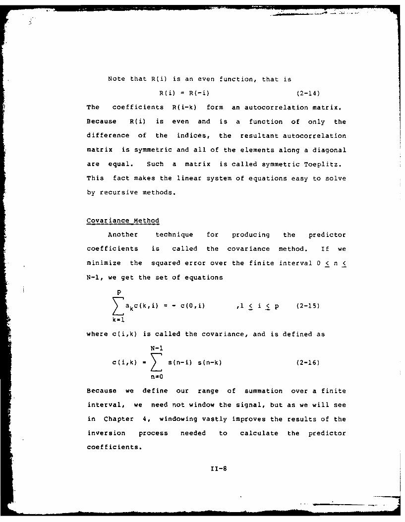
Note that R(i) is an even function, that is
R(i) = R(-i) (2-14)
The coefficients R(i-k) form an autocorrelation matrix.
Because R(i) is even and is a function of only the
difference of the indices, the resultant autocorrelation
matrix is symmetric and all of the elements along a diagonal
are equal. Such a matrix is called symmetric Toeplitz.
This fact makes the linear system of equations easy to solve
by recursive methods.
Covariance Method
Another technique for producing the predictor
coefficients is called the covariance method. If we
minimize the squared error over the finite interval 0 < n <
N-l, we get the set of equations
p
Z akc(k,i) = - c(O,i) ,l < i < p (2-15)
k=l
where c(i,k) is called the covariance, and is defined as
N-1
c(i,k) = s(n-i) s(n-k) (2-16)
n=0
Because we define our range of summation over a finite
interval, we need not window the signal, but as we will see
in Chapter 4, windowing vastly improves the results of the
inversion process needed to calculate the predictor
coefficients.
11-8

The covariance terms are symmetric, that is
c(i,k) = c(k,i) (2-17)
and make up a symmetric covariance matrix. However, the
terms of this matrix unlike the terms of the autocorrelation
matrix are not equal along the diagonals.
Solution Algorithms
The solution involves inverting the matrix which
describes the set of p equations to be solved. A number of
algorithms exist for inverting matrices with a computer. Of
main concern in developing the solution algorithms is a need
for simplicity, ease of implementation in the software, and
reduction of the number of calculations. The Toeplitz
nature of the autocorrelation matrix makes the system of p
linear equations,
p
Z akR(i-k) = -R(i) 1 < i < p (2-11)
k=l
easy to solve and reduces the number of computations
required. Leoinson developed an elegant recursive method
for solving such equations. Durbin further expanded on the
recursion by exploiting the fact that when the equation is
expanded into matrix form, the right side of the equation is
contained on the left side [Ref 7].
The recursive solution attributed to Durbin is usually
presented as [Ref 11]
11-9

1. E(0) = R(0) (2-18a)
i-i
2. k = -[R(i) - Raj(i-j)]/E(i-l) I < i < p
j=l (2-18b)
3. (i) = ki (2-18c)
4. a(i) = (i-i) _i-_
4. aj =) aj + kia i j ,1 < j j i-i (2-18d)
25. E(i) = (l-k i ) E(i-l) (2-18e)
After the values are solved recursively for i=l,2,...,p the
final solution, giving the p predictor coefficients, is
aj = aj ( p ) 1 < j < p (2-19)
The solution is unaffected if the autocorrelation values are
scaled by a constant. Usually, the autocorrelation values
are normalized by dividing them by R(O), giving normalized
autocorrelations, which, except for R(O), are all less than
one.
A by-product of the recursive method is E(i) which is
the predictor error for a predictor of order i. If the
autocorrelation function is normalized, this error value
will also be normalized. This parameter is important
because given the output filter described by the p predictor
coefficients, the value E(p) is proportional to the gain
required to reproduce the speech signal. In the prediction
model, this parameter will represent the gain of the output
filter.
The covariance method also uses a recursive method to
II-10
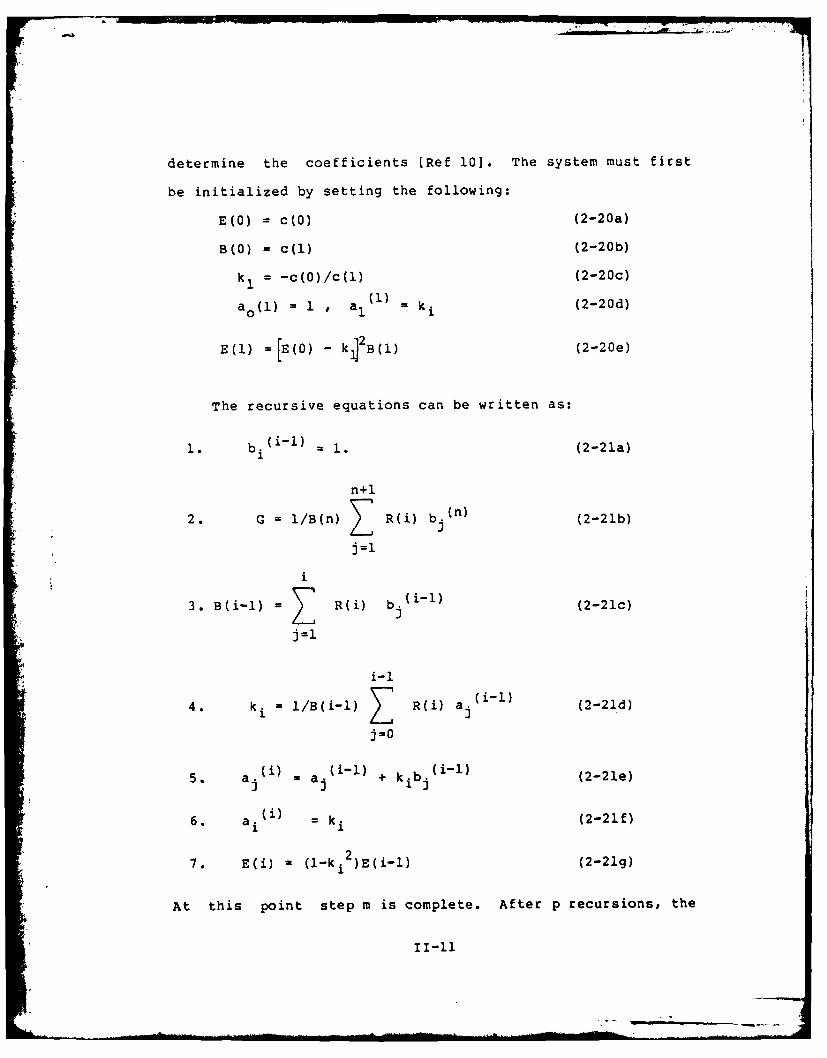
determine the coefficients [Ref 10]. The system must first
be initialized by setting the following:
E(0) = c(0) (2-20a)
B(O) = C(l) (2-20b)
k= -c(O)/c(l) (2-20c)
a 0(1) = 1 ,a 1 k (2-20d)
E(l) =[E(O) k f JB(l) (2-20e)
The recursive equations can be written as:
1. b (iil) (2-21a)
n+1
2. G = /B(n) R(i) b.(n) (2-21b)
j =1
i
3. B(i-l) =Z R(i) b~(l (2-21c)
i-i
4. k. = 1/B (i-1) T R(i) a(2-21d)
5. aj (i) =aj (i1l) + k ib.(l (2-21e)
6. a i) M (2-21f)
7. E(i) =(1-k 1 )E(i-1) (2-21g)
At this point step m is complete. After p recursions, the
final solution is
a = ai( ,i < i < p (2-22)
which gives the predictor coefficients for the output filter
of order p. The parameter E(p) is proportional to the gain
of the system.
Summary
Linear Prediction is a method of parameterizing a
signal. Using minimum mean square error techniques, the
procedure generates the filter coefficients which describe
the system producing the signal. For speech, this system is
the human vocal tract. With these coefficients and a valid
excitation to the output filter, the speech can be
reproduced to yield intelligible results.
TI-12
CHAPTER III
Development of the LPC System
To attain the flexibility required in this linear
predictive coding model, the system is divided into two
separate programs. These programs are the LPC analyzer and
the LPC speech synthesizer. Flow diagrams of these programs
are presented in figures 3-1 and 3-2. The two programs are
coupled by a file in the computer, which is called the
"channel file", and which can be considered as a
communication channel. The analyzer writes speech
information to the channel, the vocoder reads this
information and from it reproduces a synthesized version of
the original speech. Both of these driving programs are
composed of a number of subroutines which perform most of
the calculations. This extensive use of subroutines is
intended to make the system more flexible as well as easier
to understand. For the most part, bookkeeping is performed
by the main programs, whereas most of the LPC calcuations
are performed by the subroutines. Intermediate results and
parameters can be examined by looking at the relevant
subroutines. The method of calculation can also be
examined. This can be done by looking at the code or by
placing "type" or "write" statements into the subroutines.
Adding new methods simply requires the addition of the
proper subroutines and their corresponding calling
III-I

44U
E-
0 0.
clUw1
IJU ccCL4
010
aa
0
ItI 0
ini
111-2

luf
I >C 0
UA tr00
C-
C1
w~tt
111-

statements in the main program.
Further flexibility is attained by the use of
"decision variables."These decision variables are preset by
the user and control the operation of the main programs.
These variables select different prediction methods, vary
the number of poles used in the analysis, and affect other
scaling or test parameters. Two methods of setting the
decision variables are available to the user. The easiest
is to simply run the program and wait for the prompts. The
other method is to write the decision variables to a file,
with the aid of a program (SETUP) which is designed strictly
for this purpose. This method is preferred and is useful if
the user wants to hear different segments of speech without
having to worry about the decision variables selected.
Because the file is self-contained, the user need not be
interrupted by any prompts. The decision variables will be
identified and named as they are encountered in the
description of the system.
The modularity of the system helped considerably in the
construction and testing of the programs and subroutines.
Each part of the program could be tested independently
before it was consolidated into the complete program.
Modularity also allowed concurrent developement of the
analyzer and the vocoder because results from the analyzer
could be tested by direct application of the vocoder. This
also allowed various values of decision variables to be
tested at each stage of the developement.
111-4

Description of the LPC Analyzer
The input to the LPC analyzer is digitized speech. The
analyzer processes this signal and generates the parameters
which will be written to a channel file. The first stage of
the analyzer creates or opens the files to which information
will be read or written. Two files are opened, one which
contains the digitized speech to be coded, and another which
contains the decision variables. The file which contains
the incoming digitized speech must be contiguous with each
block containing 256 integer valued samples. One file, the
channel file, into which will be written the LPC speech
information, is created. Next, the decision variables are
determined, either by prompts from the terminal, or from the
file containing these variables. The variables pertaining
to the operation of the vocoder [number of poles in the
synthesis filter (POLES), pre/de-emphasis (NEMP), unvoiced
gain factor (UNGA), and the shape of the glottal pulse
(NGLT)] are then written to the channel file. This completes
the initialization of the system. The rest of the system is
a large loop which is repeated until the input speech data
is exhausted.
The first order of business within the loop is to load
a large array with five blocks of speech (each block
contains 256 samples) from the contiguous input file. This
large array is needed because this data is written to two
small arrays, one used for pitch detection, and one used for
111-5
predictor coefficient generation. Each array contains one
frame of speech. The length of each frame is set by a
decision variable (MAXFR). The large size is so that a wide
range of frame sizes can be used by the analyzer.
Using counters to keep track of where the process is in
terms of blocks and array members, a portion of the large
array is written to a smaller array. This smaller array
contains one frame of speech to be processed for energy and
pitch. This frame is first processed by the energy
subroutine. This subroutine finds the energy (sum of the
squares) in the frame to determine if the data can be
considered silence or speech. The test threshold is a
decision variable (THRESH) which is set by the user. The
energy of the frame is a functon of its length, therefore,
if the length of the frame is changed, the decision variable
THRESH should be changed by a proportional amount to
maintain consistent results. If the threshold is not
exceeded, the signal is considered silence, and no more
calculations need be made on this frame. The subroutine has
a memory of three previous energy calculations. The need for
the memory will become apparent when the nature of the pitch
detection and the synchronous nature of the analysis is
discussed.
If the frame has sufficient energy to be considered
speech and not background noise, the pitch is then
calculated. The pitch detection routines perform two tasks:
determining the voiced quality of the speech (whether the
111-6
L
frame is voiced or not), and then the pitch of the speech if
the frame is voiced. The frame for pitch is moved at an
interval (MAXPT) which is set by the user. Pitch is
therefore updated every MAXPT samples and is assumed
constant over the frame.
One method of pitch detection is essentially a
correlation process. The frame array is correlated against
itself, and the peaks which fall within an allowable range
of times are tested to find a maximum. The maximum peak is
then tested against a threshold which is set by the user.
This threshold is the decision variable STHR. If the
magnitude of the peak falls below the threshold, the speech
is declared unvoiced, otherwise it is declared voiced. The
pitch is a function of the location of the peak. Since the
range of fundamental pitch of most human speakers falls
within a fairly narrow range (70-350 Hz) [Ref 9], only a
narrow range of peak positions need to be considered. Due
to the harmonics and the formant structure of speech, the
pitch period is a difficult calculation and is quite prone
to error. Therefore interpolation is employed to smooth the
curve described by the pitch values.
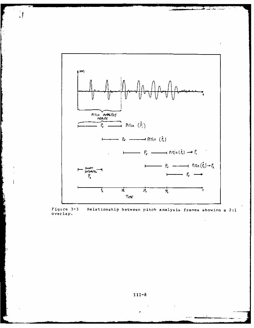
This interpolation delays the final value of the pitch
by three frames (see figure 3-3). An estimate of the pitch
in the first pitch analysis frame is computed. The frame
start is shifted by the pitch shift interval (MAXPT), and
the pitch of the second frame is estimated. Similarly, the
pitch of the third frame is estimated. These three values
111-7
P~-~ A AV n~v
FAA OIE
TiriE
Figure 3-3 Relationship between pitch analysis frames showinq a 2:1overlap.
111-8
are used to interpolate a better estimate of the pitch in
the first frame. The pitch in the following frames is
determined in a similar manner. For instance, the estimateof the fourth frame is used along with the estimates of he
second and third frame to interpolate a better estimate of
the pitch in the second frame. This delay requires that the
calculation of the predictor coefficients be equivalently
delayed. The pitch detectors must therefore have a memory
of three to perform the interpolation and to accomodate the
delay of the coefficient analysis.
After the pitch is determined by interpolation, the LPC
coefficients and the gain must be calculated. The
coefficient analysis frame can be pre-processed in a number
of different ways. If desired, the speech can be
pre-emphasized. The pre-emphasis is accomplished wih the
operation
y(n) = x(n) - .9x(n-l) (3-1)
The decision variable which controls this is NEMP. Also
available to the user is the option to window the frame. A
decision variable, Hl, controls whether or not a Hamming
window is used on the speech. After pre-processing, the LPC
calculations are straight-forward, and are performed by one
of the algorithms presented in Chapter II. A decision
variable (MP) controls which algorithm to use, and therefore
which subroutine to perform. A decision variable (POLES)
also contols the number of poles used in the analysis. The
system is unable to operate with more than 20 poles, because
111-9

of constraints on the size of some of the arrays. The
predictor coefficients are computed synchronously, that is
the start of the frame used by the coeffiecient generating
routines is set by the shift introduced by the pitch period.
This avoids the problem of having analysis extend over two
adjacent frames.
The last task during processing of each frame is to
write the relevant parameters to the channel file. These
parameters are the voiced quality of the speech, the pitch,
the output analysis frame size, the predictor coefficients,
and the gain of the system. The output analysis frame size
is the shift interval for the start of the next coefficient
analysis frame.
Description of the Synthesizer
The LPC synthesizer produces speech from the parameters
read from a channel file. The first stage of the
synthesizer program opens the channel file and creates the
file to which synthesized speech will be written. The
program is initialized by reading the first four values from
the channel file. These values are the number of poles used
in the analysis and the synthesis (POLES), the glottal pulse
shape (NGLT), the unvoiced gain factor (UNGA), and the value
of the flag indicating whether pre-emphasis was employed at
the input to the analyzer (NEMP). The unvoiced gain factor
is used to normalize the unvoiced excitation to the output
filter. The vocoder then synthesizes one variable length
III-10
iI
frame of speech at a time. The frames have varying length
because of the synchronous method of coding. To synthesize
each frame, the vocoder first reads the pitch information,
the length of the frame to be produced, and the gain. It
then reads the predictor coefficients. The pitch
information drives the synthesis process.
If the frame is voiced, an array simulating the glottal
pulse drives the digital output filter. Two pulses are
generated at intervals separated by the pitch period, and
are written to an array of length twice the period. This
array, the predictor coefficients, and the gain then drive
the subroutine NTHROAT" which is the digital output filter.
The output of this filter is the synthesized speech and is
written to the output file.
If the frame is unvoiced, a noise generation routine is
called. This double-precision routine uses a uniform random
number generator to produce a normal random number sequence.
This routine writes the sequence to an array. The gain from
the input file is scaled by the unvoiced gain factor to give
a value for the gain to drive the digital output filter.
This scaling is required because the excitation of the
filter (the noise array) is not normalized in energy with
the excitation of the filter when the speech is voiced.
This array, the predictor coefficients, and the gain then
drive the digital output filter. The output of this filter
is the synthesized speech, which is written to the output
file.
* 111
:>2
If the frame is silence, the output filter is by-passed
and zeros are written directly to the output file.
If pre-emphasis was used by the analyzer, then
de-emphasis must be employed before the speech is written to
the output file. The inverse function of the pre-emphasis
is used for this
y(n) = x(n) + .9y(n-l) (3-2)
The speech is finally scaled so that it can be listened to
by using the "AUDIOHIST" or "AUDIOMOD" programs.
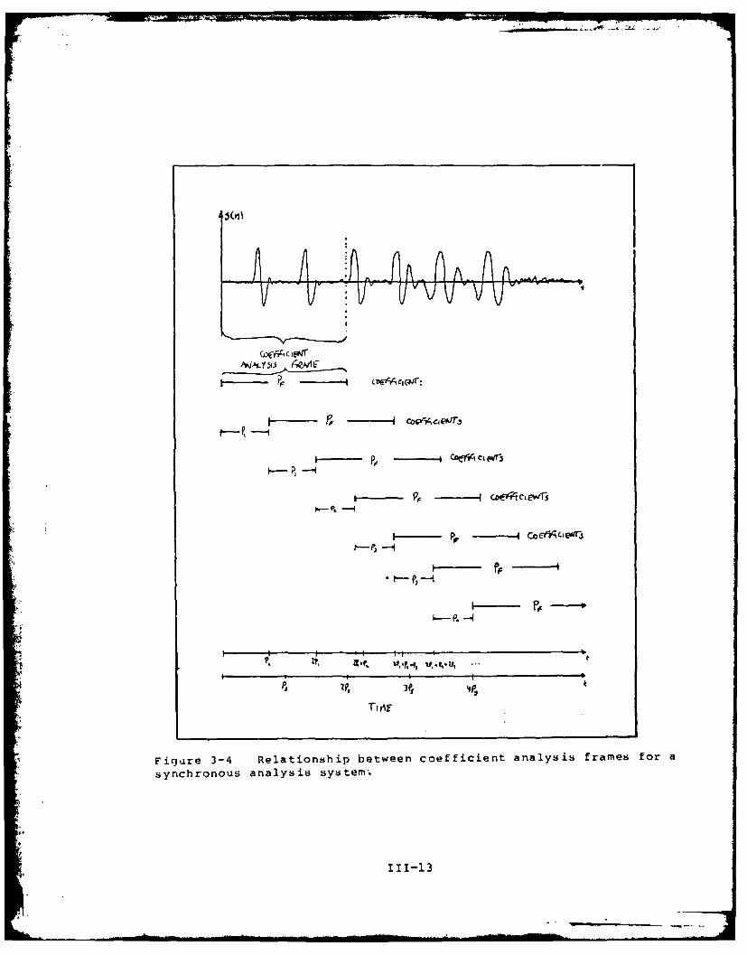
Synchronous Analysis
The LPC system developed in this thesis uses a
synchronous method of analysis. Synchronous analysis
requires an update of the predictor coefficients once every
pitch period (see figure 3-4). Because of the delay in
determining the correct pitch, the predictor coefficients
are generated with a two frame delay with respect to the
pitch detection. The shift interval of the coefficient
analysis is a multiple of the pitch period (P1 in figure
3-3). When the start of an analysis frame falls after the
start of the next pitch detection frame, the value of this
pitch (P2 ) is used as the shift interval. The frame
start is then shifted as before until a new pitch value is
needed. At this point, a new frame is estimated for pitch.
In a synchronous system, analysis on each voiced
segment of speech begins at the beginning of the pitch
period and the analysis frame is shifted at an interval
111-12
...
V- " ... v 1 v v v V . . :
91 --- ---I CA ew
I[- P. - P -P-- -
P, 4P
: ~- - P .
I 7. - -11
~.2, , ,f,.p, ,V,. ,..J f,-.
3f'~ t
Figure 3-4 Relationship between coefficient analysis frames for a
synchronous analysis system.
111-13

which is a multiple of the pitch period (see figure 3-3).
The vocoder only synthesizes the speech between the start of
every analysis frame. For this reason is the analysis frame
size written onto the channel file. Synchronous analysis
avoids the problem of having a pitch period of voiced speech
straddling the boundary between two consecutive frames.
When analysis straddles two frames, the coefficients must be
interpolated for the portion of speech reproduced over the
boundary. The interpolated values of these coefficients are
not guaranteed to give stable results.
During unvoiced speech, the shift interval is constant.
A constant frame rate (MAXFR) is used for shifting the
coefficient analysis.
The three frame delay of the pitch detector requires a
delay of the coefficient analysis by a corresponding time
period. Therefore the frame starts and boundaries of the
pitch analysis frame and the coefficient analysis frame are
different. This is the reason for the memory of the pitch
and energy detectors and the initial large array. With this
$array, the current pitch can be calculated with one portion
of the data, and used for interpolation of past pitch. At
the same time, the delayed pitch can be used to determine
the correct starting locati - in the past for predictor
coefficient generation. Therefore the system can perform
coefficient calculation in step with pitch detection. This
does tend to limit flexibility because it does not allow
asynchronous analysis.
111-14

some complexity is added because of the synchronous
nature of the analysis. For example, the bookkeeping for
each frame is doubly complex; two sets of counters must be
maintained. It is also confusing that the pitch detection
and predictor coefficient generating routines do not work on
the same data simultaneously. This requires that the
predictor coefficient generating routines operate after the
pitch has been calculated for the final frame. Substantial
gains are realized, though, because interpolation of
predictor coefficients need not be performed. Counters
would also have to be maintained in vocoder to mark the
beginning and ending of boundary-overlapping sections of
speech.
Time Constraints
Unfortunately, the system does not run in real-time. A
number of factors affect the speed of the system, among
these: the software implementation, the audio interface, and
the speed of the computer.
The biggest constraint on time is the software in the
system. Since the software is written in a high level
language, its speed is limited by the constraints of the
language. Some of these constraints are the time necessary
to write to a file and the operation rate of the
minicomputer. A hardware implementation would not be under
these constraints. The software is also a bit cumbersome in
that it must be flexible enough to operate properly with
111-15
many different possible prediction schemes. For use in the
laboratory, the transmitter and the receiver programs must
be run sequentially, whereas they would operate in parallel
if in a normal communication configuration.
Another time constraint is that the audio interface in
the lab is not prepared for real time events. The program
which performs the digital to analog calculations and
channel calling routines required to listen to the
synthesized speech must read a file first. The size of this
file is limited by the program to less than three seconds.
Therefore, long utterances are impossible to process and
listen to without interuption and user interaction with the
system.
Summary
The two-program nature of the LPC system is used to
imitate the tranmitter and receiver nature of a true
communication link. These two programs are the LPC analyzer
and the LPC synthesizer. The channel between them is a file
written in the memory of the computer. Subroutines are used
extensively to permit easy examination of internal results
and provide flexibility to run or add different subroutines
which perform the same analysis in different ways.
Synchronous analysis is employed to simplify synthesis of
the output speech.
111-16

CHAPTER IV
Testing and Results
The System
This thesis designed an LPC speech processing system
which operates in the Signal Processing Laboratory at the
Air Force Institute of Technology. It is an operational
model and replicates a number of aspects of a true LPC
speech communication system. Unfortunately, this system
does not run in real time, as it is written entirely in
software and must access and write files which reside in the
minicomputer's memory. A real LPC processor and synthesizer
would receive and transmit signals over a communication
channel, and except for buffering, would require no reading
or writing from files. Most of these operations would be
handled by more time-efficient hardware.
A simple test of the system consists of actually
processing an utterance. Each utterance is a digitized
version of a sentence spoken by a human. These utterances
or speech files are relatively noise-free so that the noise
problem of LPC would not need to be considered. These
utterances were successfully processed by the system to give
intelligible results.
To demonstrate the flexibility of the system, various
combinations of shift intervals, analysis window size,
prediction methods, pitch detection algorithms, and
IV-l
threshold values were tested. The results of these
combinations indicate that the system is flexible. Table
4-1 shows the allowable ranges of the decision variables.
The recommended values on this table indicate values for the
decision variables which seemed the give the best results.
Other testing showed that with only a very few exceptiops,
the system could handle all of the combinations with which
it was tested. The exceptions are noted below.
On occasion, especially when a low pitched voice was
processed, the vocoded speech was so unintelligible that it
was impossible to determine that an utterance was present.
This problem arises from the nature of the synchronous
analysis. Synchronous analysis demands that two shift
intervals be maintained, one for the pitch analysis window
and one for the coefficient analysis window. During voiced
speech, the shift interval for the coefficient analysis
window is based on the pitch period, but the bookkeeping
counters are based on the shift interval of the pitch
detector. If the shift interval is less than the length of
the longest pitch period during voiced speech, the analysis
window used to calculate the prediction coefficient is
incorrectly bounded. Results in this case are consistently
poor, and result in unstable filters which produce
unintelligible clicks, buzzes, and squeals. To eliminate
this problem, the frame shift interval must be increased to
accomodate the lowest pitch frequency of the file. For the
file which contained the lowest pitch this interval is
IV-2

Table 4-1
Ranges of the Decision Variables
Decision Lower Upper RecommendedVariable Limit Limit Value
POLES 6 20 16MP a - - 1MAXFR 100 400 200MAXPT b 80 200 100NEMP a - - 1NGLT a - - 3H1 a - - 1MPCH a - - 0NPCS a - - 1STHR 0.0 1.0 0.35SCAF 1.0 1000.0 1.0THRESH 0.0 1000000.0 250.0UNGA 0.001 100.0 0.1
a) These variables are flags which determine whethersubroutines will be performed or not. They do not haveupper or lower limits over a range.
b) It is recommended that the value of MAXPT be half thevalue of MAXFR. This gives a 2:1 overlap.
IV-3

between 80 and 100 samples.
Two methods of predictor coefficient generation are
included in the system and were examined extensively. Both
give acceptable results and produce intelligible speech at
the output. Although theory indicates that the covariance
method of prediction need not be windowed, much better
results are attainable when the incoming speech signal is
weighted by a Hamming window. In this context, better
results mean higher quality. Without the windowing, the
method often produces unstable output filters. With the
windowing, the resultant speech exceeded the quality of
spech produced with the autocorrelation method.
The Sift routine [Ref 9,10] for pitch detection was the
only satisfactory pitch detector implemented. The Sift
algorithm uses an inverse filtering technique to cancel the
effect of the formant structure. In a non-noise
environment, this detector can consistently differentiate
between voiced and unvoiced speech It can also successfully
determine the pitch to produce natural sounding speech. An
autocorrelation method was also examined but the algorithm
did not give consistent results. The calculated pitch was
monotone except for a disconcerting waver.
The number of poles in the analysis was also varied.
Ten poles marked a qualitative boundary between clear speech
and muffled speech. Using too few poles gave vocoded speech
which was severely muffled. With such a small number of
poles the filter does not have the resolution required to
IV-4
• 71
describe the complete formant structure of the modeled vocal
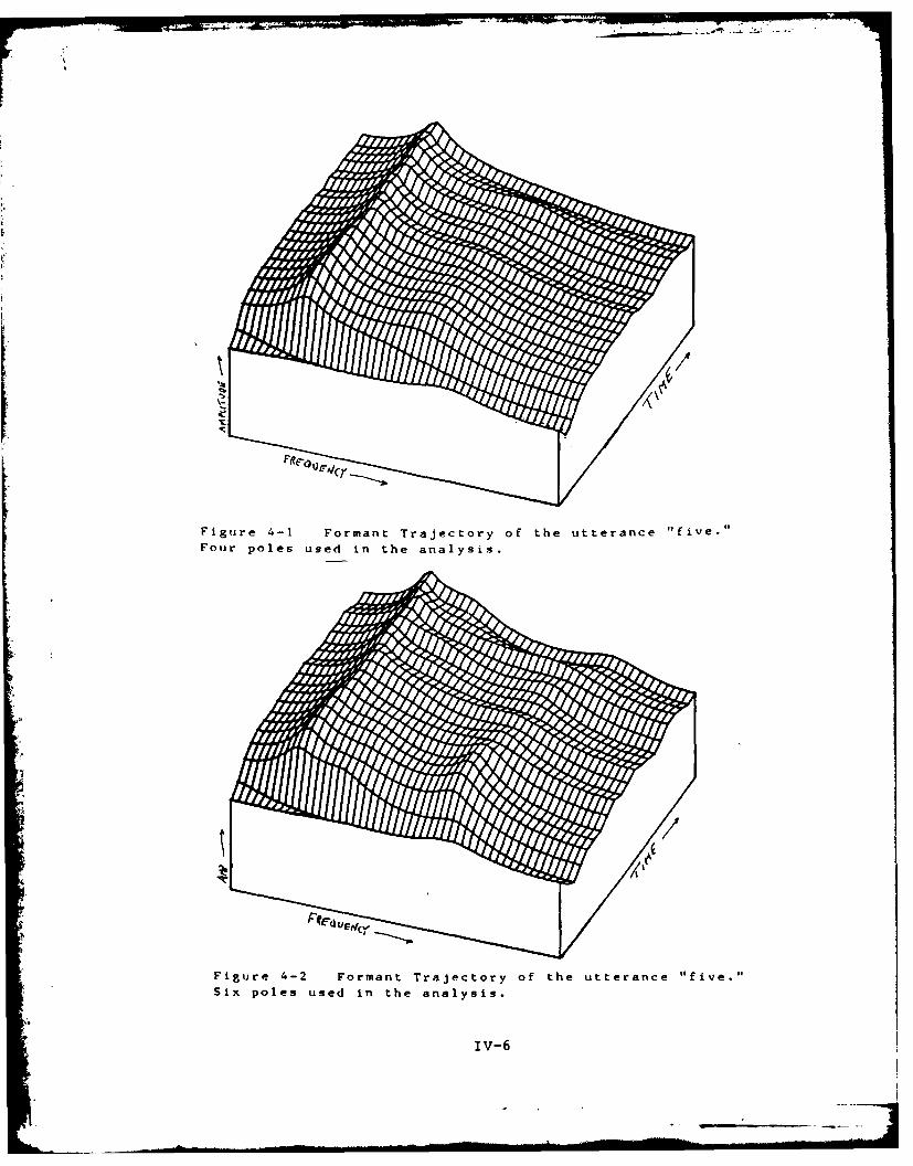
tract (see figures 4-1 to 4-5). With less than six poles,
the speech becomes unintelligible. With more than ten
poles, the quality of the resultant speech increases with
the addition of poles, with maximum quality reached at about
sixteen poles. With sixteen or more poles, the quality
remains approximately the same.
Noise
The noise was introduced to each utterance by adding a
random noise signal to the file containing the utterance.
This was accomplished with the same random noise generating
subroutine which is used to excite the vocoder during
unvoiced speech. A separate program performs this noise
addition. The maximum value of the noise can be varied to
provide noise levels from zero to considerably in excess of
the speech power. Because speech is not a stationary
process, a true signal to noise level is difficult to
calculate. It varies widely if the noise level is constant
because the speech energy varies widely from low energy in
the fricatives (s,sh,f,th...) to much higher energy in the
voiced sounds such as vowels. For our concerns, a signal to
noise ratio (SNR) was determined by calculating the power of
the noise and comparing it to the power of the voiced
portion of a clean file. Although the true SNR may vary
from frame to frame and from speech file to speech file,
consistent results are possible. That is, equivalent
IV-5
T.~
K
Figure 4-1 Formant Trajectory of the utterance "five."Four poles used in the analysis.
Figure 4-2 Formant Trajectory of the utterance "five."Six poles used in the analysis.
IV-6
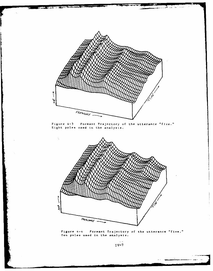
Figure 4-3 Formant Trajectory of the utterance "five."Eight poles used in the analysis.
Figure 4-4 Formant Trajectory of the utterance "five."Ten poles used in the analysis.
iv-7

Figure 4-5 Formant Trajectory of the utterance "five.
Twelve poles used in the analysis.
IV- 8

values of added noise gave approximately the sa-e SNR to all
cases (see table 4-2) and the synthesized speech suffered
the same problems of unintelligibilty.
Table 4-2
Noise
Maximum Value of Noise Power in Signal to NoiseAdded Noise the Frame (dB) Ratio-SNR (dB)
0 58 20100 61 16200 64 14500 70 8
1000 73 4
To test the effects of noise, speech files with
different signal to noise ratios were tested. Degradation
occured even with fairly small amount of added noise (SNR =
16dB). Severe degradation of the re-synthesized speech
occured with a SNR of about 8dB for the noisy input signal.
At this level, the output was unintelligible.
The analyzer consists of two parts, a pitch detector
and a prediction coefficient generating routine. These two
parts were examined to determine which is the more sensitive
to noise corruption. This was accomplished by processing
two versions of the same utterance, one which was an
unaltered version of the original speech file, and one which
was the original file plus an amount of random noise added.
These files were processed separately wihin the same
program, one for pitch and the other for the prediction
coefficients. Preliminary results indicate that the
IV-9

predictor coefficients are more susceptible to noise than is
the pitch detection.
With this processing scheme, four permutations of noisy
and clean files are possible. Two permutations use the same
file for pitch detection and coefficient generation. One
performs pitch detection on a clean file and coefficient
generation on a noisy file, and one performs pitch detection
on a noisy file and coefficient generaton on a clean file.
The clean/clean test was used as a control example and
the other permutations were examined for a qualitative
analysis of intelligibility. The signal to noise ratio was
maintained constant over all of the files. Noisy speech
files with a SNR of 8dB gave unintelligible results but were
identifiable as speech, so this level was used as the noisy
file. The mixed analysis (noisy/clean, clean/noisy) gave
interesting results. The noisy coefficient/clean pitch gave
highly degraded speech which was only slightly better than
the noisy/nolisy analysis. Contrasting with this, the clean
coefficient/noisy pitch gave only slightly degraded results.
Three of the five tests were noticably degraded, yet still
intelligible. Two were virtually indistiguishable from the
clean/clean example. It was expected that the noise would
degrade the pitch detection severely and render any
reproducton unintelligible. In the five tests, this was not
the case: the predictor coefficient generating algorithm
failed. This can be heard in the output speech and seen in
a plot of the frequency response of the ensemble of the
IV-lO
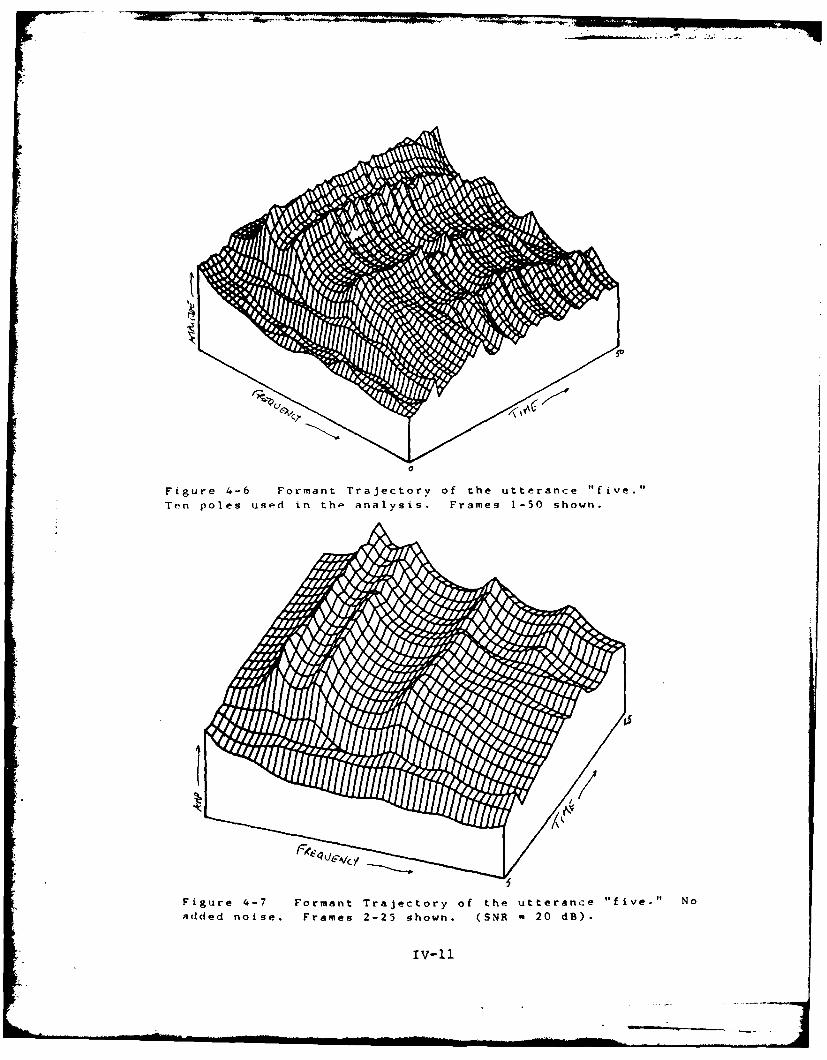
Figure 4-6 Formant Trajectory of the Utterance "five."
Ten poles used in thp analysis. Frames 1-50 shown.
Figure 4-7 Formant Trajectory of the utterance "five." No
added noise. Frames 2-25 shown. (SNR m20 dB).
'V-11
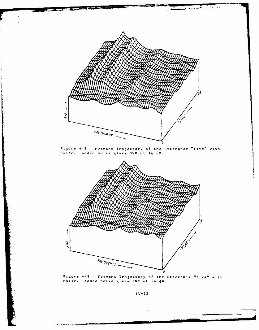
Figure 4.-8 Formant Trajectory of the utterance "five" with
noise. Added noise gives SNR of 1 dB.
IV-12

FR FOICA]f
Figure 4-10 Formant Trajectory of the utterance "five" wit'noise. Added noise gives SNR of 8 dB.
Figuire '.-tl Formant Trajectory of the utterance "five" with
noisp. Addled noise gives SNR of 4 dR.
iv-13
digital filters (figures 4-6 to 4-11). The formant
structure is lost in the noise; only the first formant can
be located and identified on these plots.
To further examine this phenomenon, the glottal pulse
excitation of the outp - filter was replaced by the random
noise excitation. The results in this case sounded like a
whispered utterance, but were still intelligible. In fact,
preliminary results indicate that in a high noise
environment, intelligibility can be gained by neglecting
pitch information at the output and generate the utterance
with only only a random excitation to the output filter.
The waveshape of the synthesized speech was examined to
possibly locate the source of the unintelligibilty. It was
determined that the voiced frames in the synthesized speech
are the main cause of the squeals and buzzes which make the
speech unintelligible.
IV-14
CHAPTER V
Conclusions and Recommendations
Conclusions
This report describes a system which processes speech
using linear predictive methods. The system is a software
simulation of an LPC analyzer and synthesizer. The system
consists of two programs, one of which processes the speech
to generate the LPC parameters, and another which processes
these parameters to resynthesize the speech. An important
aspect of the system is that it enables the user to select
from various pitch and coefficient analysis methods. It
also allows the user to vary other parameters in order to
simulate other changes in the processing scheme.
To test the operation of the system, a regimen of
testing was performed by varying the different parameters.
A separate program allows a simple method for changing all
of the parameters over which the user has control. These
parameters are called the decision variables and each has an
allowable range of values. The system operated
satisfactorally over all values of the decision variables.
The flexibilty exhibited by the system in this testing
indicates that the system can be a valuable tool for the
study of linear predictive coding of speech in the Signal
Processing Lab at AFIT.
Some of the parameters which were tested extensively
V-I
were the number of poles in the analysis, the different
methods of analysis and pitch detection. It was determined
that ten poles give a reasonable representation af speech.
The covariance method of detection exceeded the
autocorrelation method with respect to quality of output
speech. The SIFT pitch detection routine far exceeded the
AUTOC method in determining pitch.
Also examined were some of the noise problems of LPC.
Various noise levels were tested to determine at which level
noise corruption rendered the LPC system useless. This
level was found to be at a signal to noise ratio of about
8dB. Another important result was that the coefficient
generation was greatly affected by noise. The effect of the
predictor coefficients was much greater than the effect of
the pitch detection. This result may be useful in exploring
techniques to counter the effects of noise corruption.
Recommendations
The linear predictive coding system presented in this
thesis can be used as a firm foundation for more study in
the process of linear predictive coding of speech.
Continuing effort with this project could extend in two
general directions. One direction would be software
oriented with further work being done to expand the system
with more subroutines. The other general direction is
oriented to studying more about LPC using the system as a
tool.
V-2

Further Work in Software Development
Part of the flexibilty of the system stems from the
extensive use of subroutines. Additional subroutines could
be incorptrated into the system to expand the present
capabilities of the LPC anlyzer. Perhaps the first task to
be attempted would be to incorporate the recursive LPC
method as developed by Capt Willis Janssen [Ref 4] into this
system. This would offer an opportunity to compare this
method with some of the more common techniques which have
been implemented in the current system. A lattice
formulation of the predictor coefficients would offer
another method of analysis. This method is decribed in the
book by Rabiner and Schafer [Ref 101. An undebugged version
of a possible subroutine implementation is presented in
Appendix D.
Other useful additions to the present system would be
additional pitch detection methods. The AUTOC method might
be altered slightly to give better results. The current
literature describes other methods of pitch detection. The
system would be greatly enhanced if it offered the
availablity of more methods with which to analyze the input
speech signal.
A process for simulating the bit rates actually
transmited over the channel would be a useful addition. At
present, all quanization is done in 2 byte (16 bit)
segments. The coefficients sent over the channel are 4 byte
V-3
floating point words. The flags sent over the channel
require at most 2 bits each, but each is quantized as 16 bit
integers. The pitch is likewise represented as a 16 bit
integer. It could easily be represented with fewer bits.
The frame size information sent over the channel is
redundant and could be eliminated. All of these
compressions could reduce the effective bit rate of the
communicated signal.
Also needed is a better interface with the audio input
and output. The present means to listen to processed speech
is to move the file containing the speech to another
directory (on a different system even) and invoke another
program. This method is time consuming and reduces the
effectiveness of a synthesize-listen-compare atmosphere of
testing.
Further Testing
Since this simulation was designed as a tool to study
the process of linear predictive coding of speech, it seems
only natural that considerable further testing can be
imagined. A fine place to start further research is with
the ubiquitous noise problem.
A possible technique for reducing the effect of noise
was discovered in this work. The technique is to ignore the
pitch detector information. If all speech is presumed to be
unvoiced, the synthesized speech will resemble whispered
speech. In noise, the greatest difference between the input
V-4
speech and the output speech occured during periods of the
utterance declared to be voiced speech. I recommend this
technique to be further explored.
Dr Kabrisky is interested in a method of compressing
the formant frequencies while maintaining the ratio between
them. This system models the human speech production system
with the poles of a digital filter. These poles describe
the formant locations. Therefore digital processing
techniques could be used to shift the poles and consequently
the formants.
One final recommendaton is to use this system as a
means to study the speech recognition capabilities of LPC.
Other research has shown the feasibilty of LPC for speech
recognition tasks [Ref 2]. The feature vector as described
by the predictor coefficients is easily extractable from
this system. The flexibilty of the system offers the user
to vary a wide range of parameters in search for a set which
expedites recognition.
V-5
Bibliography
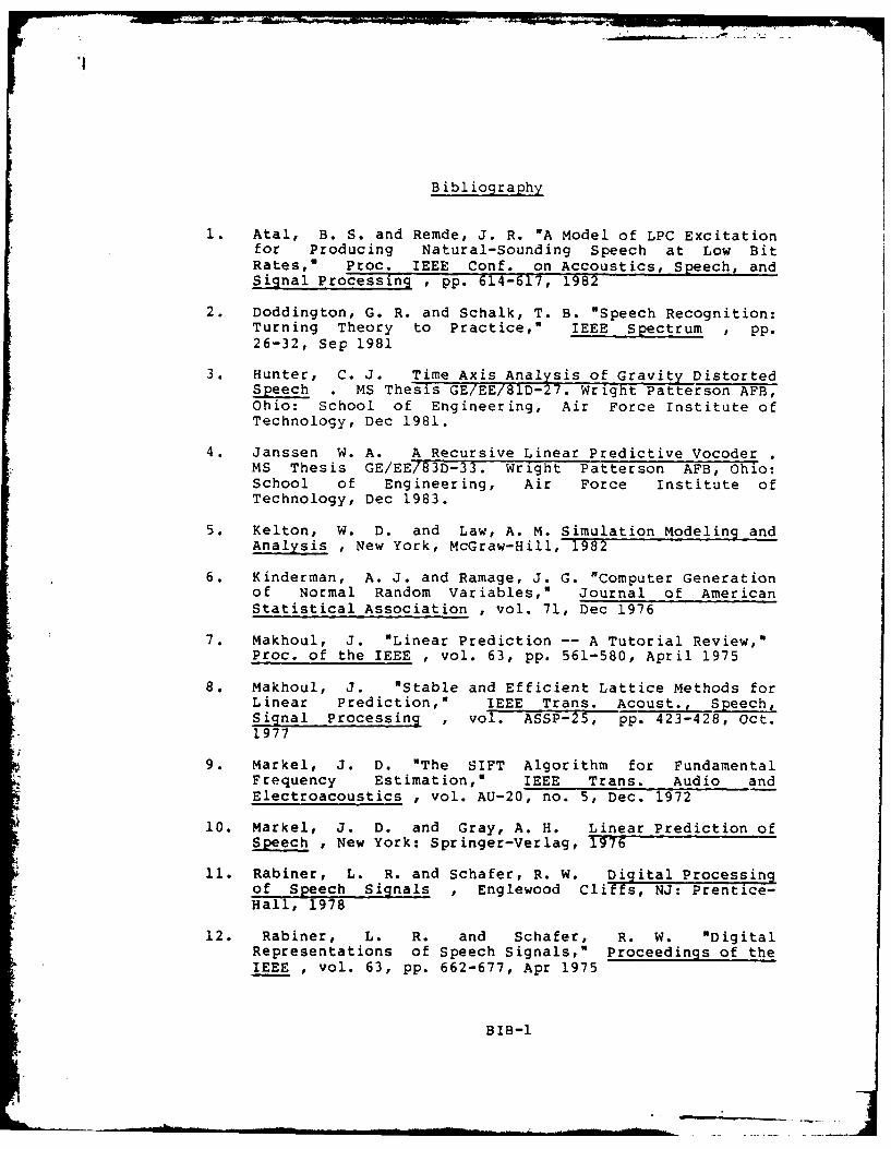
1. Atal, B. S. and Remde, J. R. "A Model of LPC Excitationfor Producing Natural-Sounding Speech at Low BitRates," Proc. IEEE Conf. on Accoustics, Speech, andSignal Processing , pp. 614-617, 1982
2. Doddington, G. R. and Schalk, T. B. "Speech Recognition:Turning Theory to Practice," IEEE Spectrum , pp.26-32, Sep 1981
3. Hunter, C. J. Time Axis AnalZsis of Gravity DistortedSpeech . MS Thesis GE/EE/81D-27. Wright Patterson AFB,Ohio: School of Engineering, Air Force Institute ofTechnology, Dec 1981.
4. Janssen W. A. A Recursive Linear Predictive VocoderMS Thesis GE/EE/83D-33. Wright Patterson AFB, Ohio:School of Engineering, Air Force Institute ofTechnology, Dec 1983.
5. Kelton, W. D. and Law, A. M. Simulation Modeling andAnalysis , New York, McGraw-Hill, 1982
6. Kinderman, A. J. and Ramage, J. G. "Computer Generationof Normal Random Variables," Journal of AmericanStatistical Association , vol. 71, Dec 1976
7. Makhoul, J. "Linear Prediction -- A Tutorial Review,"Proc. of the IEEE , vol. 63, pp. 561-580, April 1975
8. Makhoul, J. "Stable and Efficient Lattice Methods forLinear Prediction," IEEE Trans. Acoust., Speech,Signal Processing , vol. ASSP-25, pp. 423-428, Oct.1977
9. Markel, J. D. "The SIFT Algorithm for FundamentalFrequency Estimation," IEEE Trans. Audio andElectroacoustics , vol. AU-20, no. 5, Dec. 1972
10. Markel, J. D. and Gray, A. H. Linear Prediction ofSpeech , New York: Springer-Verlag, 1976
11. Rabiner, L. R. and Schafer, R. W. Digital Processing0f Speech Signals , Englewood Cliffs, NJ: Prentice-Hall, 1978
12. Rabiner, L. R. and Schafer, R. W. "DigitalRepresentations of Speech Signals," Proceedings of theIEEE , vol. 63, pp. 662-677, Apr 1975
BIB-I

13. Rosenburg, A. E. "Effects of Glottal Pulse Shape on theQuality of Natural Vowels," J. Acoust. Soc. Am. , vol.49, pp 583-590, Feb 1971
I
BI--

APPENDIX A
User's Manual
A-1
USER'S MANUAL
A LINEAR PREDICTIVE CODING SYSTEM
DESIGNED AND WRITTEN BYLT CRAIG E. MCKOWN
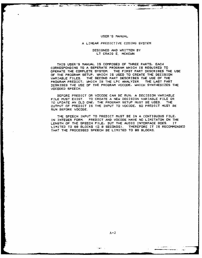
THIS USER'S MANUAL IS COMPOSED OF THREE PARTS, EACH
CORRESPONDING TO A SEPERATE PROGRAM WHICH IS REQUIRED TOOPERATE THE COMPLETE SYSTEM. THE FIRST PART DESCRIBES THE USEOF THE PROGRAM SETUP, WHICH IS USED TO CREATE THE DECISIONVARIABLE FILES. THE SECOND PART DESCRIBES THE USE OF THEPROGRAM PREDICT, WHICH IS THE LPC ANALYZER. THE LAST PARTDESRIBES THE USE OF THE PROGRAM VOCODE, WHICH SYNTHESIZES THEVOCODED SPEECH.
BEFORE PREDICT OR VOCODE CAN BE RUN, A DECISION VARIABLE
FILE MUST EXIST. TO CREATE A NEW DECISION VARIABLE FILE ORTO UPDATE AN OLD ONE, THE PROGRAM SETUP MUST BE USED. THEOUTPUT OF PREDICT IS THE INPUT TO VOCODE, SO PREDICT MUST BERUN BEFORE VOCODE.
THE SPEECH INPUT TO PREDICT MUST BE IN A CONTIGUOUS FILE,
IN INTEGER FORM. PREDICT AND VOCODE HAVE NO LIMITATON ON THE
LENGTH OF THE SPEECH FILE, BUT THE AUDIO INTERFACE DOES. ITLIMITED TO 88 BLOCKS (2.8 SECONDS). THEREFORE IT IS RECOMMENDEDTHAT THE PROCESSED SPEECH BE LIMITED TO 88 BLOCKS.
A-2
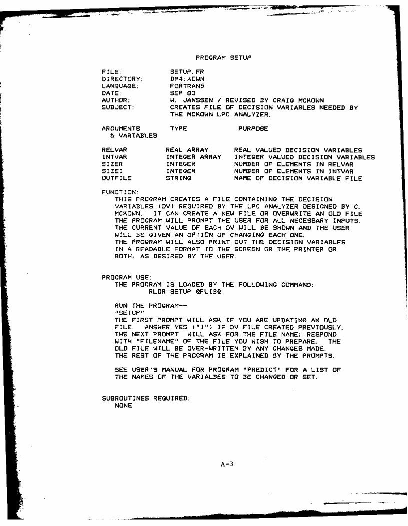
PROGRAM SETUP
FILE: SETUP. FRDIRECTORY: DP4:KOWNLANGUAGE: FORTRAN5DATE: SEP 83AUTHOR: W. JANSSEN / REVISED BY CRAIG MCKOWNSUBJECT: CREATES FILE OF DECISION VARIABLES NEEDED BY
THE MCKOWN LPC ANALYZER.
ARGUMENTS TYPE PURPOSE& VARIABLES
RELVAR REAL ARRAY REAL VALUED DECISION VARIABLESINTVAR INTEGER ARRAY INTEGER VALUED DECISION VARIABLESSIZER INTEGER NUMBER OF ELEMENTS IN RELVARSIZEI INTEGER NUMBER OF ELEMENTS IN INTVAROUTFILE STRING NAME OF DECISION VARIABLE FILE
FUNCTION:THIS PROGRAM CREATES A FILE CONTAINING THE DECISIONVARIABLES (DV) REQUIRED BY THE LPC ANALYZER DESIGNED BY C.MCKOWN. IT CAN CREATE A NEW FILE OR OVERWRITE AN OLD FILETHE PROGRAM WILL PROMPT THE USER FOR ALL NECESSARY INPUTS.THE CURRENT VALUE OF EACH DV WILL BE SHOWN AND THE USERWILL BE GIVEN AN OPTION OF CHANGING EACH ONE.THE PROGRAM WILL ALSO PRINT OUT THE DECISION VARIABLESIN A READABLE FORMAT TO THE SCREEN OR THE PRINTER ORBOTH, AS DESIRED BY THE USER.
PROGRAM USE:THE PROGRAM IS LOADED BY THE FOLLOWING COMMAND:
RLDR SETUP @FLIB@
RUN THE PROGRAM--"SETUP"THE FIRST PROMPT WILL ASK IF YOU ARE UPDATING AN OLDFILE. ANSWER YES ("I") IF DV FILE CREATED PREVIOUSLY.THE NEXT PROMPT WILL ASK FOR THE FILE NAME; RESPONDWITH "FILENAME" OF THE FILE YOU WISH TO PREPARE. THEOLD FILE WILL BE OVER-WRITTEN BY ANY CHANGES MADE.THE REST OF THE PROGRAM IS EXPLAINED BY THE PROMPTS.
SEE USER'S MANUAL FOR PROGRAM "PREDICT" FOR A LIST OFTHE NAMES OF THE VARIALBES TO BE CHANGED OR SET.
SUBROUTINES REQUIRED:NONE
A-3
CHANGES:ADDING NEW DECISION VARIABLES IS NOT DIFFICULT.ADDITIONAL SPACE REMAINS IN EACH DV ARRAY FOR AT LEASTFIVE MORE VARIABLES. THE PROGRAM MUST BE UP-DATED INFOUR PLACES FOR EACH ADDITIONAL VARIABLE.1) IN THE *** UPDATE ARRAYS *** SECTION. FOLLOW
THE FORMAT OF THE OTHER VARIABLE UPDATES. YOUMUST CHANGE THE LINE NUMBER AFTER THE "IFOGOTO"IN THE UPDATE PRECEDING THE ADDITIONAL UPDATE.
2) IN THE *** TYPE ARRAYS *** SECTION. FOLLOW THEFORMAT OF THE OTHER TYPE STATEMENTS.
3&4) IN THE *** OUTPUT FILE *** SECTION. A NEW WRITESTATEMENT AND FORMAT STATEMENT MUST BE ADDED FOREACH NEW VARIABLE FOLLOW THE FORMAT OF THE OTHERWRITE AND FORMAT STATEMENTS.
EXAMPLE:
A-4
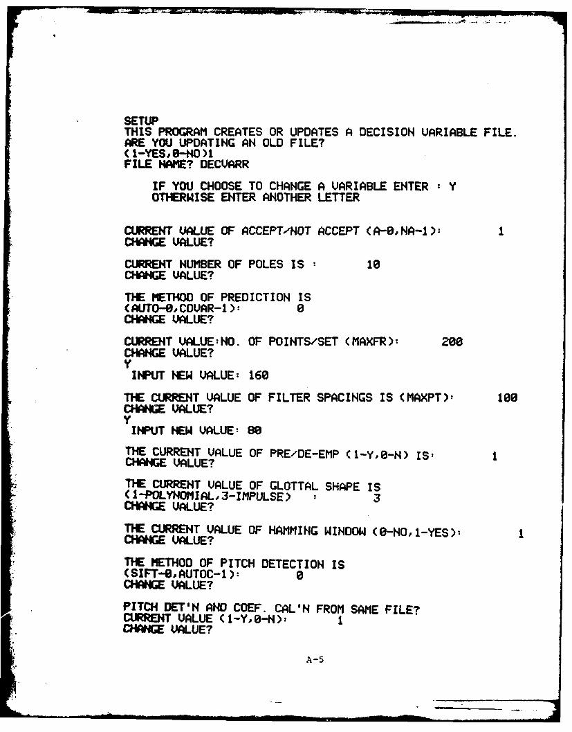
SETUPTHIS PROGRAM CREATES OR UPDATES A DECISION VARIABLE FILE.ARE YOU UPDATING AN OLD FILE?(1-YES -NO )1FILE NAME? DECVARR
IF YOU CHOOSE TO CHANGE A VARIABLE ENTER : YOTHERWISE ENTER ANOTHER LETTER
CURRENT VALUE OF ACCEPT/NOT ACCEPT (A--,NA-I):CHAWGE VALUE?
CURRENT NUMBER OF POLES IS 10CHANGE VALUE?
THE METHOD OF PREDICTION IS(AUTO-@, COUAR-1 0CHANGE VALUE?
CURRENT UALUE:NO. OF POINTS/SET (MAXFR): 200CHANGE VALUE?
INPUT NEW VALUE: 160
THE CURRENT VALUE OF FILTER SPACINGS IS (MAXPT)- 100CHANGE VALUE?
INPUT NEW VALUE: 80
THE CURRENT VALUE OF PRE/DE-EMP (1-YO-N) IS:CHANGE VALUE?
TIE CURRENT VALUE OF GLOTTAL SHAPE IS(1-POLYNOMIAL.3-IMPULSE) : 3CHANGE VALUE?
THE CURRENT VALUE OF HAMMING WINDOW (0-HO, 1-YES):CHANGE VALUE?
THE METHOD OF PITCH DETECTION IS(SIFT--, AUTOC-1): 0CHANGE VALUE?
PITCH DET'N AND COEF. CAL'N FROM SAME FILE?CURRENT VALUE (1-Y,O-N)t ICHARNGE VALUE?
A-5
U I .
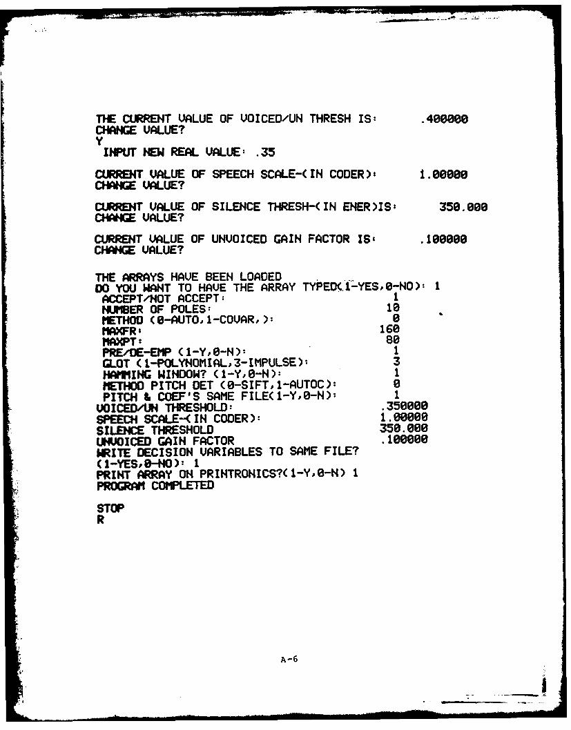
THE CURRENT VALUE OF VOICED/UN THRESH IS: .400000CHANGE VALUE?Y
INPUT HEW REAL VALUE: .35
CLRRENT VALUE OF SPEECH SCALE-( IN CODER), 1.00000CHANGE VALUE?
CURRENT VALUE OF SILENCE THRESH-(IN ENER)IS, 350.000CHANGE VALUE?
CURRENT VALUE OF UNVOICED GAIN FACTOR IS, .100000CHANGE VALUE?
THE ARRAYS HAVE BEEN LOADEDDO YOU WANT TO HAVE THE ARRAY TYPED( -YES,0-HO): 1ACCEPT/NOT ACCEPT: 1NUMBER OF POLES: 10METHOD (8-AUTO,1-COVAR,): 0MAXFR' 160
PREDE-EIP (1-Y,O-N): 1GLOT (i-POLYHOMIAL,3-IMPULSE)- 3HAMMING WINDOW? (1-Y,0-N): 1METHOD PITCH DET (0-SIFT, 1-AUTOC): 0PITCH & COEF'S SAME FILE(1-Y,O-N): I
VOICED/UH THRESHOLD: .350000SPEECH SCALE-(IN CODER): 1.00000SILENCE THRESHOLD 350. 000UNVOICED GAIN FACTOR .100000
WRITE DECISION VARIABLES TO SAME FILE?(1-YES,-NO): 1PRINT ARRAY OH PRINTRONICS?(I-YO-H) 1PRORAM COMPLETED
STOPR
A-6
f ....

DECVARR
DATE 2/12/83
TIME 13:56:47
ACCEPT/NOT ACCEPT 1
NUMBER OF POLES 10
METHOD (0-AUTO, 1-COVAR) 0
MAXFR 160
MAXPT 80
PRE/DE-EMP? (1-Y,O-N) 1
GLOTTAL PULSE (1-POLY ,3-IMPULSE) 3
HAMMING WINDOW? (1-Y,O-N) 1
METHOD PITCH DET (0-SIFT, 1-AUTOC) 0
PITCH & COEF's F'M SAME FILE(1-Y,O-N) 1
VOICED/UNVOICED THRESHOLD .35000
SPEECH SCALE 1.00000
SILENCE THRESHOLD 350.00000
UNVOICED GAIN FACTOR .10000
A-7

PROGRAM PREDICT
FILE: PREDICT. FRDIRECTORY: DP4:KOWNLANGUAGE: FORTRAN5DATE: SEP 83AUTHOR: CRAIG MCKOWNSUBJECT: DIGITAL PROCESSING OF SPEECH--LINEAR PREDICTION ANALYZER
ARGUMENTS TYPE PURPOSE& VARIABLES
MAXPT INTEGER SAMPLES BETWEEN PITCH DETECTIONMAXFR INTEGER SAMPLES IN ANALYSIS WINDOWNSET INTEGER COUNTER FOR PITCH FRAME NUMBERNFRAME INTEGER COUNTER FOR LPC FRAME NUMBERNPTS INTEGER NUMBER OF SAMPLE POINTS ANALYZEDK,S,KS,JS,JK INTEGERS COUNTERS (USED FOR BOOKKEEPING)P1 INTEGER COUNTER FOR NUMBER OF SAMPLES TO
START OF NEXT LPC ANALYSIS WINDOWJUMP INTEGER FLAG INDICATING NATURE OF PREVIOUS
FRAME OF SPEECH (VOICEDUNVOICED ORSILENCE)
SPEEFL1 STRING NAME OF SPEECH FILE (FOR LPC)SPEEFL2 STRING NAME OF SPEECH FILE (FOR PITCH)DUMMY STRING NAME OF FILE HOLDING DECISION VARIABLESPARAM STRING NAME OF FILE TO WHICH LPC DATA IS
WRITTEN (ACTS AS TRANSMISSION CHANNEL)DECISION VARIABLES
POLES INTEGER NUMBER OF POLES IN THE OUTPUT FILTERMP INTEGER METHOD OF PREDICTION
(0-AUTOCOR',I-COVARIANCE)NGLT INTEGER GLOTTAL PULSE SHAPE
(1-POLYNOM',2-TRIGON',3-IMPULSE)MPCH INTEGER METHOD OF PITCH DETECTION
(0-SIFT, 1-AUTOC)NPCS INTEGER PITCH/LPC FILES THE SAME (0-NO, I-YES)NEMP INTEGER PRE/DE-EMPHASIS (0-NO, I-YES)HI INTEGER HAMMING WINDOW (0-NO, 1-YES)STHR REAL VOICED/UNVOICED THRESHOLD
(USED FOR PITCH DETECTION)SCAF REAL SCALE FACTOR (INPUT SPEECH DIVIDED BY
THIS TO AVOID OVERFLOW)THRESH REAL SPEECH/SILENCE THRESHOLDUNGA REAL UNVOICED GAIN FACTOR (OUTPUT; UNVOICED
INPUT TO OUTPUT FILTER MULTIPLIED BYTHIS TO PREV
A-8

VARIABLES (CONT.)
VAL INT ARRAY DUMMY ARRAY TO HOLD THE SAMPLED SPEECHBEFORE IT IS WRITTEN TO SPEE & SPCH
SPEE REAL ARRAY ARRAY HOLDING DATA FOR LPC COEFFICIENTGENERATION
SPCH REAL ARRAY ARRAY HOLDING DATA FOR PITCH DETECTIONAR REAL ARRAY ARRAY HOLDING THE LPC COEFFICIENTS
AR(l)=AOAR(2)=Al... AR(POLES)=AP.ONLY AR(2) TO AR(POLES) ARE WRITTEN TOTHE CHANNEL FILE
RCOF REAL ARRAY REFLECTION COEFFICIENTSAENRG REAL ARRAY ENERGY FROM ENERGY DETECTORPITCH REAL ARRAY PITCH FROM PITCH DETECTORPIT INTEGER INTERPOLATED PITCH (WRITTEN TO CHANNEL)VOCD INTEGER FLAG INDICATING NATURE OF SPEECH
(WRITTEN TO CHANNEL)AL REAL ALPHA, ERROR COEFFICIENT, USED AS GAIN
FOR OUTPUT CHANNEL. COMPUTED IN COEF-FICIENT GENERATING ROUTINES.
FUNCTION:THIS PROGRAM EMULATES THE ANALYSIS OF A LINEAR PREDICTIVECODING SCHEME. IT INPUTS SAMPLED SPEECH DATA AND PRODUCESTHE PARAMETERS REQUIRED BY A VOCODER TO REPRODUCE THE SPEECH.THESE PARAMETERS ARE WRITTEN TO A FILE WHICH ACTS AS THECOMMUNICATION CHANNEL. FOR MORE INFORMATION, SEE MCKOWNTHESIS.THE FORM OF THE CHANNEL FILE IS COMPATIBLE TO THE VOCODERPROGRAM BY THE SAME AUTHOR.
PROGRAM USE:THE PROGRAM IS LOADED WITH THE FOLLOWING COMMAND:
RLDR PREDICT IOF SIFTB ENER DCOVAR DIRECT DAUTO AUTOC 2FLIB@
BEFORE RUNNING THIS PROGRAM, IT IS ADVISED THAT THE USERCREATE (OR UPDATE) A FILE CONTAINING THE DECISION VARIABLESREQUIRED TO PROPERLY EXECUTE THIS PROGRAM. THIS IS EASILYACCOMPLISHED BY USING THE PROGRAM "SETUP." SEE USER'S MANUALFOR THE PROGRAM "SETUP."I RECOMMEND THAT A MACRO FILE IS EMPLOYED TO RUN THISPROGRAM AND THE VOCODER PROGRAM USED TO SYNTHESIZE THESPEECH. THE MACRO FILE SHOULD BE OF THE FORM:
PREDICT SPEECHFILEI/C SPEECHFILE2/P DECVAR/I CHANNELFILE/O
THE FILE SPEECHFILEI IS THE NAME OF THE INPUT SPEECH FILEUSED FOR THE PREDICTOR COEFFICIENT GENERATION. THE FILESPEECHFILE2 IS THE NAME OF THE INPUT SPEECH FILE USED TOACCOMPLISH THE PITCH DETECTION. THE FILE DECVAR IS THE NAME
A-9
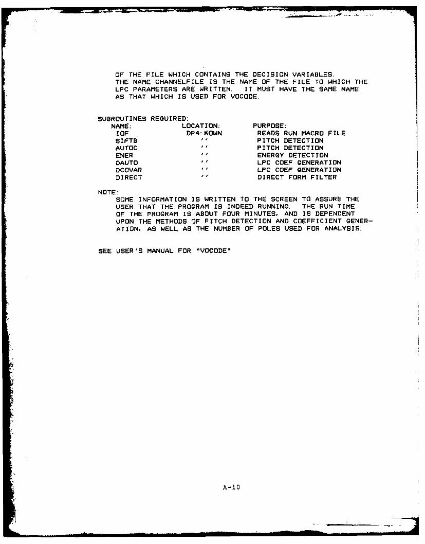
OF THE FILE WHICH CONTAINS THE DECISION VARIABLES.THE NAME CHANNELFILE IS THE NAME OF THE FILE TO WHICH THELPC PARAMETERS ARE WRITTEN. IT MUST HAVE THE SAME NAMEAS THAT WHICH IS USED FOR VOCODE.
SUBROUTINES REQUIRED:NAME: LOCATION: PURPOSE:IOF DP4:KOWN READS RUN MACRO FILESIFTB A" PITCH DETECTIONAUTOC '' PITCH DETECTIONENER "' ENERGY DETECTIONDAUTO '' LPC COEF GENERATIONDCOVAR '' LPC COEF GENERATIONDIRECT '' DIRECT FORM FILTER
NOTE:SOME INFORMATION IS WRITTEN TO THE SCREEN TO ASSURE THEUSER THAT THE PROGRAM IS INDEED RUNNING. THE RUN TIMEOF THE PROGRAM IS ABOUT FOUR MINUTES, AND IS DEPENDENTUPON THE METHODS OF PITCH DETECTION AND COEFFICIENT GENER-ATION, AS WELL AS THE NUMBER OF POLES USED FOR ANALYSIS.
SEE USER'S MANUAL FOR "VOCODE"
A-1O

PROGRAM VOCODE
FILE: VOCODE. FRDIRECTORY: DP4:KOWNLANGUAGE: FORTRAN 5DATE: SEP 83AUTHOR: CRAIG MCKOWNSUBJECT: DIGITAL PROCESSING OF SPEECH
LINEAR PREDICTION VOCODER
ARGUMENTS TYPE PURPOSE& VARIABLES
SPEEFL STRING NAME OF A DUMMY FILE (NOT USED)PARAM STRING NAME OF FILE FROM WHICH LPC DATA IS
READ (ACTS AS TRANSMISSION CHANNEL)DUMMY STRING NAME OF A DUMMY FILE (NOT USED)RUMMY STRING NAME OF THE FILE TO WHICH DIGITIZED
SPEECH IS WRITTEN (OUTPUT FILE)
SPEECH HAS BEEN NORMALIZED FOR AUDIOOUTPUT WITH "AUDIOHIST"
AR REAL ARRAY LPC COEFFICIENTS READ FROM THE CHANNELFILE. AR(1) IS THE AR(2) FROM THECODER PROGRAM "PREDICT"
POLES INTEGER NUMBER OF POLES OF THE OUTPUT FILTERVOCD INTEGER FLAG INDICATING UNVOCD/VOICED DECISION
FROM CODERPIT INTEGER PITCH PERIOD IN SAMPLES READ FROM
CHANNEL FILEIX DP INT SEED NUMBER FOR SUBROUTINE "UNVOCD"U REAL ARRAY OUTPUT OF "VOICED" OR "UNVOCD" - INPUT
TO "THROAT"W REAL ARRAY MEMORY FOR "THROAT"S REAL ARRAY OUTPUT OF THROAT - VOCODED SPEECHINTS INT ARRAY INTEGER VALUES OF S - WRITTEN IN BLOCK
FORM TO OUTPUT FILEX INT ARRAY USED FOR WRBLK AND RDBLKIS, IPoKS INTEGERS COUNTERS
FUNCTION:THIS PROGRAM EMULATES THE VOCODER OF A LINEAR PREDICTIVECODING SCHEME. IT TAKES AS INPUTS THE LPC PARAMETERSFROM A FILE WHICH ACTS AS THE COMMUNICATION CHANNEL, ANDUSES THESE TO REPRODUCE DIGITAL SPEECH. FOR MORE INFORMATIONSEE THE MCKOWN THESIS.THIS PROGRAM WAS WRITTEN TO BE USED IN CONJUNCTION WITH THELPC CODER PROGRAM, "PREDICT" BY THE SAME AUTHOR.
A-II
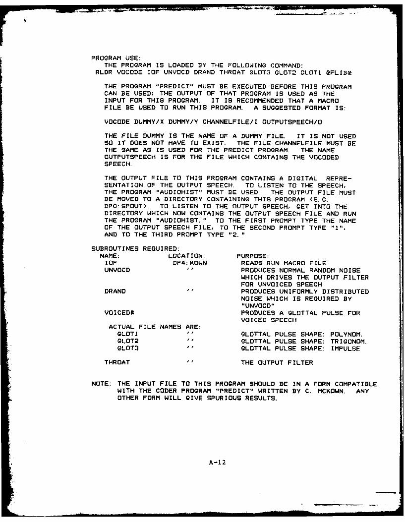
I -- ;Rim
PROGRAM USE:THE PROGRAM IS LOADED BY THE FOLLOWING COMMAND:
RLDR VOCODE IOF UNVOCD DRAND THROAT GLOT3 GLOT2 GLOT1 @FLIB@
THE PROGRAM "PREDICT" MUST BE EXECUTED BEFORE THIS PROGRAMCAN BE USED; THE OUTPUT OF THAT PROGRAM IS USED AS THEINPUT FOR THIS PROGRAM. IT IS RECOMMENDED THAT A MACROFILE BE USED TO RUN THIS PROGRAM. A SUGGESTED FORMAT IS:
VOCODE DUMMY/X DUMMY/Y CHANNELFILE/I OUTPUTSPEECH/O
THE FILE DUMMY IS THE NAME OF A DUMMY FILE. IT IS NOT USEDSO IT DOES NOT HAVE TO EXIST. THE FILE CHANNELFILE MUST BETHE SAME AS IS USED FOR THE PREDICT PROGRAM. THE NAMEOUTPUTSPEECH IS FOR THE FILE WHICH CONTAINS THE VOCODEDSPEECH.
THE OUTPUT FILE TO THIS PROGRAM CONTAINS A DIGITAL REPRE-SENTATION OF THE OUTPUT SPEECH. TO LISTEN TO THE SPEECH,THE PROGRAM "AUDIOHIST" MUST BE USED. THE OUTPUT FILE MUSTBE MOVED TO A DIRECTORY CONTAINING THIS PROGRAM (E.G.DPO:SPOUT). TO LISTEN TO THE OUTPUT SPEECH, GET INTO THEDIRECTORY WHICH NOW CONTAINS THE OUTPUT SPEECH FILE AND RUNTHE PROGRAM "AUDIOHIST." TO THE FIRST PROMPT TYPE THE NAMEOF THE OUTPUT SPEECH FILE, TO THE SECOND PROMPT TYPE "1",AND TO THE THIRD PROMPT TYPE "2."
SUBROUTINES REQUIRED:NAME: LOCATION: PURPOSE:IOF DP4:KOWN READS RUN MACRO FILEUNVOCD "o PRODUCES NORMAL RANDOM NOISE
WHICH DRIVES THE OUTPUT FILTERFOR UNVOICED SPEECH
DRAND of PRODUCES UNIFORMLY DISTRIBUTEDNOISE WHICH IS REQUIRED BY"UNVOCD"
VOICED# PRODUCES A GLOTTAL PULSE FORVOICED SPEECH
ACTUAL FILE NAMES ARE:GLOTI op GLOTTAL PULSE SHAPE: POLYNOM.GLOT2 " GLOTTAL PULSE SHAPE: TRIGONOM.GLOT3 '' GLOTTAL PULSE SHAPE: IMPULSE
THROAT THE OUTPUT FILTER
NOTE: THE INPUT FILE TO THIS PROGRAM SHOULD BE IN A FORM COMPATIBLEWITH THE CODER PROGRAM "PREDICT" WRITTEN BY C. MCKOWN. ANYOTHER FORM WILL GIVE SPURIOUS RESULTS.
A-12
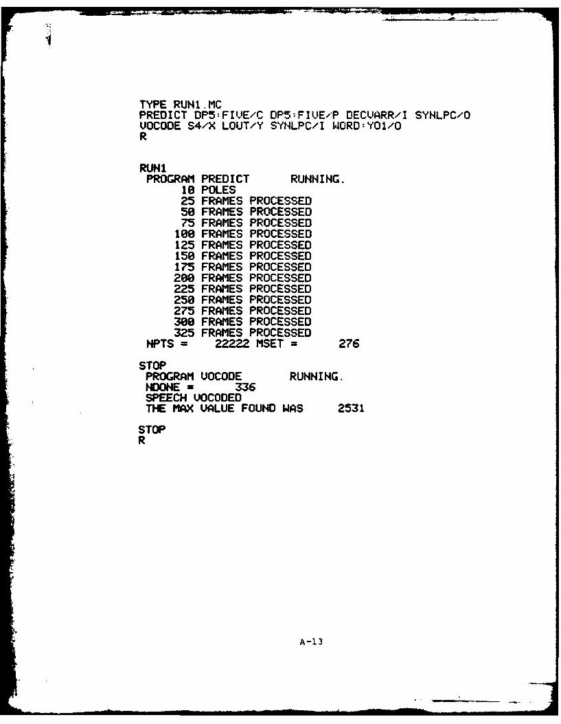
TYPE RUNI.MCPREDICT DP5:FIVE/C OPS:FIVE/P DECUARR/I SYNLPC/OVOCODE S4/X LOUT/Y SYHLPC/I WORD:YO1/OR
RUN1PROGRAM PREDICT RUNNING.
10 POLES25 FRAMES PROCESSED50 FRAMES PROCESSED75 FRAMES PROCESSED
108 FRAMES PROCESSED125 FRAMES PROCESSED150 FRAMES PROCESSED175 FRAMES PROCESSED288 FRAMES PROCESSED225 FRAMES PROCESSED258 FRAMES PROCESSED275 FRAMES PROCESSED380 FRAMES PROCESSED325 FRAMES PROCESSED
NPTS = 22222 MSET = 276
STOPPROGRAM VOCODE RUNNING.HIONE = 336SPEECH VOCODEDTHE MAX VALUE FOUND WAS 2531
STOPR
A-13

APPENDIX S
Program Listings
B-1
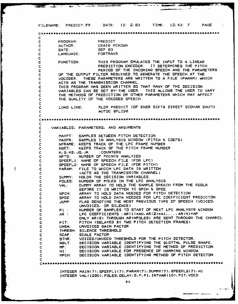
FILENAME: PREDICT.FR DATE: 12: 2:83 TIME: 13:43: 7 PAGE
C*****************************************************************.********CC PROGRAM: PREDICTC AUTHOR: CRAIG MCKOWN
C DATE: SEP 83
C LANGUAGE: FORTRAN5CC FUNCTION: THIS PROGRAM EMULATES THE INPUT TO A LINEAR
C PREDICTION ENCODER. IT DETERMINES THE PITCH
C PERIOD OF THE INCOMING SPEECH AND THE PARAMETERS
C OF THE OUTPUT FILTER REQUIRED TO GENERATE THE SPEECH AT THE
C VOCODER. THESE PARAMETERS ARE WRITTEN TO A FILE (PARAM) WHICH
C ACTS AS THE TRANSMISSION CHANNEL.
C THIS PROGRAM HAS BEEN WRITTEN SO THAT MANY OF THE DECISIONC VARIABLES CAN BE SET BY-THE USER. THIS ALLOWS THE USER TO VARY
C THE METHODS OF PREDICTION OR OTHER PARAMETERS WHICH MAY AFFECT
C THE QUALITY OF THE VOCODED SPEECH.CC LOAD LINE: RLDR PREDICT IOF ENER SIFTB DIRECT DCOVAR DAUTO
C AUTOC @FLIB@C
CC VARIABLES, PARAMETERS, AND ARGUMENTSCC MAXPT: SAMPLES BETWEEN PITCH DETECTIONC MAXFR: SAMPLES IN ANALYSIS WINDOW (PITCH & COEFS)
C NFRAME: KEEPS TRACK OF THE LPC FRAME NUMBER
C NSET: KEEPS TRACK OF THE PITCH FRAME NUMBER
C K,S, KS, JSJK :COUNTERSC NPTS: NUMBER OF POINTS ANALYZED
C SPEEFLI: NAME OF SPEECH FILE (FOR LPC)
C SPEEFL2: NAME OF SPEECH FILE (FOR PITCH)
C PARAM: FILE TO WHICH LPC DATA IS WRITTEN
C (ACTS AS THE TRANMISSION CHANNEL)
C DUMMY: HOLDS THE DECISION VARIABLES
C POLES: NUMBER OF POLES IN THE LPC ANALYSIS
C VAL: DUMMY ARRAY TO HOLD THE SAMPLE SPEECH FROM THE RDILK
C BEFORE IT IS WRITTEN TO SPCH & SPEE
C SPCH: ARRAY TO HOLD DATA NEEDED FOR PITCH DETECTION
C SPEE: ARRAY TO HOLD DATA NEEDED FOR LPC COEFFICIENT PREDICTON
C JUMP: FLAG DENOTING THE MOST PREVIOUS TYPE OF SPEECH (VOICED,
C UNVOICED, OR SILENCE)
C P1 " NUMBER OF SAMPLES TO START OF NEXT LPC ANALYSIS WINDOW
C AR : LPC COEFFICIENTS :AR(1)=A0,AR(2)=A1,... ,AR(N)=AP
C ONLY AR(2) THROUGH AR(NPOLES) ARE SENT THROUGH THE CHANNEL
C PIT: PITCH (DELAYED BY TWO PITCH DETECTION FRAMES)
C UNGA: UNVOICED GAIN FACTOR
C THRESH: SILENCE THRESHOLD
C SCAF: SCALE FACTOR
C STHR: VOICED/UNVOCD THRESHOLD FOR THE PITCH DETECTOR.
C NGLT: DECISION VARIABLE IDENTIFYING THE GLOTTAL PULSE SHAPE.
C MP: DECISION VARIABLE IDENTIFYING THE METHOD OF PREDICTION.
C HI: DECISION VARIABLE FOR PRESENCE OF HAMMING WINDOW.
C MPCH: DECISION VARIABLE IDENTIFYING METHOD OF PITCH DETECTON.
C
INTEGER MAIN(7),SPEEFLI(7),PARAM(7),DUMMY(7),SPEEFL2(7),HIINTEGER VAL(1280),POLESDELAYS,FP1, INTVAR(1O),PITVOCD
!.*

PAGE 2INTEGER NAL(1280)DIMENSION SPCH(400),PI3UF(100),PITCH(3),AR(20),RCOF(20)DIMENSION SPEE(400),RELVAR(l0),AENRG(3)
DATA NPTS, NFRAME, NSET, K JKJEND/0, 0,0, 0,0, 0/DATA SKSJUMPJS/1,1 ,li/DATA PITCH/3*0. 0/, AENRG/3*0. 0/DATA YMEMN/O. 0/MAXPT = 160 ;DEFAULT VALUESMAXFR = 320NFILES = 4
C*** CALL lOF AND OPEN ALL REQUIRED FILES.CALL IOF(NFILES, MAIN1 SPEEFLI, SPEEFL2, DUMMY, PARAM, MS, 51. 2, S3, S4)
CALL OPEN(1,SPEEFL1,11 IER) ; SPEECH FILE (LPC)CALL OPEN(4,SPEEFL2,1,JER) ; SPEECH FILE (PITCH)IF((IER.NE.1).OR. (JER.NE.1)) TYPE "OPEN FILE ERROR ",IERJER
CALL OPEN(21 DUMMY,3,JER) ;DECISION VARIABLESIF(JER. NE. 1) TYPE "OPEN FILE ERROR ",JER
CALL DFILW(PARAM,JER) ;LPC PARAMETERSIF (JER. EQ.13) GO TO 40IF (JER.NE. 1) TYPE "DELETE FILE ERROR ",JER
40 CALL CFILW(PARAM,2,JER)IF (,JER. NE. 1) TYPE "CREATE FILE ERROR ",JERCALL OPEN(3, PARAM, 3, JER)IF(JER.NE.1) TYPE "OPEN FILE ERROR ",JER
C*** GET DECISION VARIABLESREAD (2,42) (RELYAR(I)1 1=1, 10)READ (2,43) (INTVAR(I). 1=1, 15)
42 FORMAT(3X,F12. 5)43 FORMAT(3X. 110)
IF(INTVAR(1).EQ. 1) GO TO 45
ACCEPT "NUMBER OF POLES IN THE LPC FILTER: ",POLESACCEPT "METHOD OF PREDICTION: 0-AUTOCORR, 1-COVARIANCE",MPACCEPT "METHOD OF PITCH DETECTION: 0-SIFT, 1-AUTDC",MPCHACCEPT "THRESHOLD (SILENCE/SPEECH): ",THRESHACCEPT "PRE/DE-EMPHASIZE? (YES-i, NO-0): ", NEMPACCEPT "UNVOICED GAIN FACTOR (UNGA): ",UNQAACCEPT "SCALE FACTOR (SCAF): ",SCAFACCEPT 'VOICED/UNVOCD THRESHOLD: "1,STHRACCEPT "GLOTTAL PULSE SHAPE(1-POLY,3-IMPULSE): ",NGLTACCEPT "HAMMING WINDOW? (1-Y.0-N): ",HlACCEPT "PITCH AND COEFFICIENT FILES THE SAME?(O-NO~i-YES)",NPCSGO TO 46
45 POLES -INTVAR(2)MP = INTVAR(3)MAXFR -INTVAR(4)MAXPT -INTVAR(5)NEMP - INTVAR(6)NGLT - INTVAR(7)Hi = INTVAR(S)MPCH - INTVAR(9)NPCS - INTVAR(iO)STHR - RELVAR(1)

PAGE 3SCAF = RELVAR(2)THRESH = RELVAR(3)UNGA = RELVAR(4)
46 TYPE POLES," POLESNPOLES = POLES + 1MAXFR1 = MAXFR - I ;FOR HAMMING WINDOWWRITE BINARY(3) POLESNEMP,UNGANGLT CHANNEL WRITE
C*** THE OPERATIONAL PROGRAM...
C*** START OF LOOP50 CONTINUE
CvI** READ IN A NEW BLOCK OF DATACALL RDBLK(loK,VALo5,IER) ; READ THE SPEECH INTO AN ARRAYIF (IER. EQ. 9) GO TO 260IF (IER. NE. 1) TYPE "READ FILE ERROR ", IER
C*** START A NEW FRAME OF PITCH DETECTION52 NSET = NSET + 1
NPOINT = 0F = S + MAXFR - IIF(NPCS. EQ.O) GO TO 60DO 55 J=S,F
NPOINT=NPOINT+ISPCH(NPOINT) = FLOAT(VAL(J))/SCAF ; SPCH FOR SIFT & ENER
55 CONTINUEGO TO 61
C*** USED IF PITCH AND COEFFICIENT FILES ARE DIFFERENT60 CALL RDBLK(4,KNAL,5oIER) ; READ THE SPEECH INTO AN ARRAY
IF (IER. EQ. 9) GO TO 260IF (IER.NE.1) TYPE "READ FILE ERROR ", IERDO 61 J=S,F
NPOINT=NPOINT+ISPCH(NPOINT) = FLOAT(NAL(J))/SCAF ; SPCH FOR SIFT & ENER
61 CONTINUE
C*** CALCULATE ENERGY IN A FRAME62 CALL ENER(SPCH, THRESH, NEN, AENRGMAXFR)
IF (NEN. EQ.O) GO TO 65 . NO NEED TO GET PITCH
C*** CALL TO THE SUBROUTINES WHICH PERFORM PITCH ANALYSIS63 IF(MPCH. EQ.O) CALL SIFTA(SPCHPITCHSTHR,MAXFR)
IF(MPCH. EQ. 1) CALL AUTOC(SPCHoPITCH, STHR, MAXFR)
65 DELAY = NSET - 2!F (DELAY. LE.0) GO TO 225 ; TRUE PITCH IS DELAYED
C*** GET PREDICTION COEFFICIENTS70 CONTINUE
NFRAME = NFRAME + IIF((MOD(NFRAME, 25)).EG.O) TYPE NFRAME," FRAMES PROCESSED"IF(AENRG(3).LT. THRESH) GO TO 204 NO NEED TO FIND COEFFICIENTS
DO 75 I = 1,20
I . . ... . . .. R 3-

PAGE 4RCOF(I) 0.0 INITIALIZE ARRAYSAR(I) = 0.0 FOR PREDICTION
75 CONTINUE ; COEFFICIENTSAL =0.0NPOINT = 0F = KS + MAXFR - 1 A COUNTER
C*** LOAD ARRAY AND PREEMPHASIZE FOR COEFFICIENT GENERATIONIF(H1. EQ.0) GO TO 179 ; NO NEED FOR HAMMING WINDOWIF(NEMP. EQ.O) GO TO 81 ; NO PRE-EMPHASISDO 80 J = KSF
YMEMD = FLOAT(VAL(J))*(. 54-.46*COS(NPOINT*6. 28318/MAXFRI))SP1 = YMEMD - .9*YMEMN
NPOINT = NPOINT + 1SPEE(NPOINT) = SPI/SCAFYMEMN = YMEMD
80 CONTINUEGO TO 82
C*** NO PRE-EMPHASIS81 DO 82 J = KS,F
SPI = FLOAT(VAL(J))*(. 54-.46*COS(NPOINT*6.28318/MAXFR1))
NPOINT = NPOINT + 1SPEE(NPOINT) = SPI/SCAF
82 CONTINUEGO TO 189
C*** NO HAMMING WINDOW179 IF(NEMP. EQ.0) GO TO 181 ; NO PRE-EMPHASIS
DO 180 J = KS,FYMEMD = FLOAT(VAL(J))SPi = YMEMD - .9*YMEMN
NPOINT = NPOINT + 1SPEE(NPOINT) = SP1/SCAFYMEMN = YMEMD
180 CONTINUEGO TO 189
C*** NO PRE-EMPHASIS181 DO 182 J = KS,F
NPOINT = NPOINT + 1SPEE(NPOINT) = FLOAT(VAL(J))/SCAF
182 CONTINUE189 CONTINUE
C*** CALL TO SUBROUTINE TO DETERMINE THE FILTER COEFFICIENTS
190 IF (MP. EQ.0) CALL AUTO(MAXFRSPEE,POLES,ARALRCOF)IF (MP. EG. I) CALL COVAR(MAXFR, SPEE, POLES, AR, AL, RCOF)
C*** CALCULATE VALUES TO BE WRITTEN TO THE CHANNELIF (PITCH(3).EG.0.0) GO TO 200 ;UNVOICED SPEECH
C*** VOICED SPEECHPIT = INT(PITCH(3))VOCD = IP1 = 2*PITIF(JUMP. NE.0) P1 = P1/2 ; IF PREVIOUS SET NOT VOICED,IF((PI.GT.MAXPT).AND.(JUMP.EG.O)) P1 - P1/2JS = JS + PI , MORE FREQUENT ANALYSIS
KS = KS + PI.JUMP - 0
GO TO 210
, "-5'
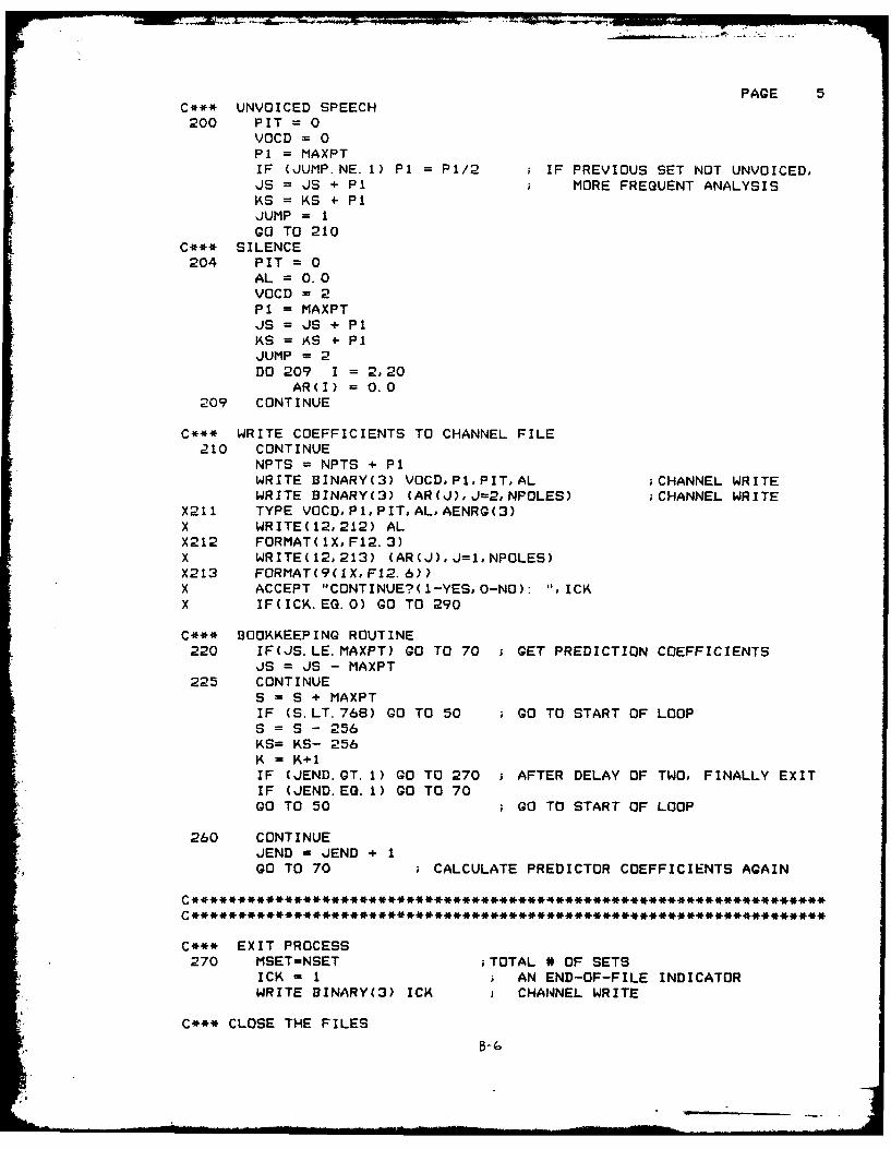
PAGE 5C*** UNVOICED SPEECH200 PIT= 0
VOCD = 0PI = MAXPTIF (JUMP.NE.1) P1 = P1/2 ; IF PREVIOUS SET NOT UNVOICED,JS = JS + P1 MORE FREGUENT ANALYSISKS = KS + P1JUMP = 1GO TO 210
C*** SILENCE204 PIT = 0
AL = 0.0VOCD = 2P1 = MAXPTJS = JS + P1KS = AS * P1JUMP = 2DO 209 I = 2.20
AR(I) = 0.0209 CONTINUE
C*** WRITE COEFFICIENTS TO CHANNEL FILE'210 CONTINUE
NPTS = NPTS + P1WRITE BINARY(3) VOCDmPlPITAL ;CHANNEL WRITEWRITE BINARY(3) (AR(J),J=2,NPOLES) ;CHANNEL WRITE
X211 TYPE VOCD,P1,PITAL, AENRG(3)X WRITE(12,212) ALX212 FORMAT(IX, F12.3)X WRITE(12,213) (AR(J),J=loNPOLES)X213 FORMAT(9(1X,F12.6))X ACCEPT "CONTINUE?(1-YES, 0-NO): ",ICKX IF(ICK. EQ.0) GO TO 290
C*** BOOKKEEPING ROUTINE220 IF(JS.LE.MAXPT) GO TO 70 GET PREDICTION COEFFICIENTS
JS = JS - MAXPT225 CONTINUE
S = S + MAXPT
IF (S. LT. 768) GO TO 50 gO TO START OF LOOPS = S - 258KS= KS- 256K - K+IIF (JEND.GT. 1) GO TO 270 ; AFTER DELAY OF TWO, FINALLY EXITIF (JEND. EQ. 1) GO TO 70GO TO 50 ; GO TO START OF LOOP
260 CONTINUEJEND = JEND + 1GO TO 70 ; CALCULATE PREDICTOR COEFFICIENTS AGAIN
C*** EXIT PROCESS270 MSET-NSET ;TOTAL # OF SETS
ICK -I ; AN END-OF-FILE INDICATORWRITE BINARY(3) ICK ; CHANNEL WRITE
C*** CLOSE THE FILES,. B-6

PAGE 6290 CALL CLOSEC1,IER)
CALL CLOSE(4,JER)IF ((IER. NE. 1). OR. (JER. NE. 1)) TYPE "CLOSE FILE ERROR " IER, JERCALL CLDSE(2,IER)CALL CLDSE(3,JER)IF ((IER.NE. 1).OR. (JER.NE. 1)) TYPE "CLOSE FILE ERROR '.IER,JER
TYPE "NPTS = ',NPTS, ' MSET =". MSETSTOPEND
5-7

FILENAME: IOF.FR DATE: 12: 2:83 TIME: 13:44:52 PAGE
SUBROUTINE IOF(N,MAINF1,F2,F3,F4,MS,S1.S2,S3,S4)
C ADAPTED FROM SUBROUTINE WRITTEN BY LT. SIMMONS 10 SEPT 81CC THIS FORTRAN 5 SUBROUTINE WILL READ FROM THE FILE COM.CMC (FCOM.CM IN THE FORE GROUND) THE PROGRAM NAME,ANY GLOBALC SWITCHES, AND UP TO FOUR LOCAL FILE NAMES AND CORRESPONDINGC LOCAL SWITCHES.CC ARGUMENTS:CC N IS THE NUMBER OF LOCAL FILES AND SWITCHES TO BE READ FROMC (F)COM.CM. N MUST BE 1, 2, 3, OR 4.CC MAIN IS AN ASCII ARRAY FOR THE MAIN PROGRAM FILE NAME.CC Fl, F2, F3, AND F4 ARE THE FOUR ASCII ARRAYS TO RETURN THEC LOCAL FILE NAMES.CC MS IS A TWO-WORD INTEGER ARRAY THAT HOLDS ANY GLOBAL SWITCHESCC 51, S2, S3, AND S4 ARE TWO-WORD INTEGER ARRAYS THAT HOLD THEC LOCAL SWITCHES CORRESPONDING TO Fl THROUGH F4 RESPECTIVELY.C
DIMENSION MAIN(7),MS(2)INTEGER Fl(7),F2(7)9 F3(7),F4(7),Sl(2),S2(2),S3(2)5S4(2)
C CHECK BOUNDS ON NIF(CN.LT.l).OR.(N.GT.4)) STOP ;N OUT OF BOUNDS
C PROCESS THE DATA IN (F)COM. CMCALL GROUND(I) ;FIND OUT WHICH GROUND PROGRAM IS INIF(I.EQ.0)OPEN 01 "COM. CM" ;OPEN CH. 0 TO COM.CMIF(I.EG.1)OPEN O."FCOM.CM" ;OPEN CH. 0 TO FCOM.CMCALL COMARG(OMAINMSIER) ;READ FROM (F)COM.CMIF( IER. NE. 1) TYPE" COMARG ERROR: ", IERWRITE(1O,1) MAIN(1) ;TYPE PROGRAM NAME
1 FORMAT(' PROGRAM ',S13. 'RUNNING.)CALL COMARGCO,Fl,Sl,JER) ;READ FROM (F)COM.CMIF(JER.NE.1) TYPE" COMARG ERROR (Fl):",JE-RIF(N.EQ.1) GO TO 2 ;TEST NCALL COMARG(0,F2,S2,KER) ;READ FROM (F)COM.CMIF(KER.NE.1) TYPE" COMARG ERROR (F2):",KERIF(N. EQ.2) GO TO 2 ;TEST NCALL COMARG(0.F3,S3,LER) ;READ FROM (F)COM.CMIF(LER.NE.1) TYPE" COMARG ERROR (F3):",LERIF(N. EQ.3) GO TO 2 ;TEST NCALL COMARG(0,F4,S4,LER) ;READ FROM (F)COM.CMIFCLER.NE.l) TYPE" COMARO ERROR (F4):".LER
h2 CLOSEO0RETURNEND

FILENAME: ENER.FR DATE: 12: 2:83 TIME: 13: 42:24 PAGE
CC THIS SUBROUTINE DETERMINES WHETHER A FRAMES ENERGYC EXCEEDS A SILENCE THRESHOLD (NEN=O:SILENCE; NEN=I:SPEECH)CC AENRG IS A THREE-MEMBER ARRAY WHICH HOLDS A MEMORY OF THEC PREVIOUS VALUES OF THE COMPUTED ENERGY.CC******************************************************************
SUBROUTINE ENER(SPCHo THRESH, NEN, AENRG, MAXFR)
DIMENSION SPCH(1),AENRG(1)NEN = 1 PRESET DECISION TO SPEECHSUM = 0.0 INITIALIZE SUMDO 100 J=1,MAXFR
$1 = SPCH(J)SUM = SUM + $1 * S ; ENERGY = SUM OF SGUARES
100 CONTINUEAENRG(3) = AENRG(2)AENRG(2) = AENRG(1)AENRG(1) = SUMIF(SUM. LT. THRESH) NEN = 0RETURNEND
0-10
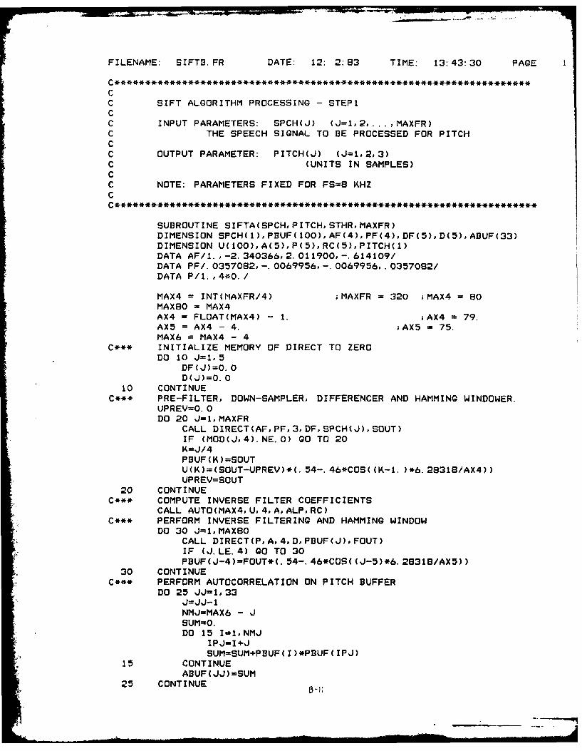
FILENAME: SIFTB.FR DATE: 12: 2:83 TIME: 13:43:30 PAGE
CC SIFT ALGORITHM PROCESSING - STEP1CC INPUT PARAMETERS: SPCH(J) (J=1,2,. .. ,MAXFR)C THE SPEECH SIGNAL TO BE PROCESSED FOR PITCHCC OUTPUT PARAMETER: PITCH(J) (J=1.2,3)C (UNITS IN SAMPLES)CC NOTE: PARAMETERS FIXED FOR FS=8 KHZC
SUBROUTINE SIFTA(SPCH, PITCH, STHR, MAXFR)DIMENSION SPCH( 1), PIUF( 100), AF(4), PF(4), DF(5), D(5), ABUF(33)DIMENSION U(100), A(5),P(5),RC(5), PITCH(1)DATA AF/l. ,-2. 340366,2. 011900,-. 614109/DATA PF/. 0357082, -. 0069956. -'0069956, .0357082/DATA P/l.,4*0./
MAX4 =INT(MAXFR/4) iMAXFR = 320 ;MAX4 =80
MAX8O MAX4AX4 = FLOAT(MAX4) - 1. ;AX4 =79.
AX5 = AX4 - 4. ;AX5 75.MAX6 =MAX4 - 4
C*** INITIALIZE MEMORY OF DIRECT TO ZERODO 10 J=1,5
DFCJ)=O. 0D(J)=0. 0
10 CONTINUEC*** PRE-FILTER, DOWN-SAMPLER, DIFFERENCER AND HAMMING WINDOWER.
UPREV=0. 0DO 20 J=,MAXFR
CALL DIRECT(AF,PF,3,DF,SPCH(J),SOUT)IF (MOD(J,4). NE. 0) GO TO 20
PJ3UF(K)=SOUTU(K)=(SOUT-UPREV)*(. 54-. 46*COS((K-1. )*6.28318/AX4))UPREY=SOUT
20 CONTINUEC*** COMPUTE INVERSE FILTER COEFFICIENTS
CALL AUTO(MAX4. U.4, A.ALP, RC)C*** PERFORM INVERSE FILTERING AND HAMMING WINDOW
DO 30 J=1,MAX8OCALL DIRECT(Po,.4, D,PBUF(J).FOUT)IF (J.LE.4) GO TO 30PBUF(J-4)-FOUT*(. 54-. 46*COS( (J-5)*6. 28318/AX5))
30 CONTINUEC*** PERFORM AUTOCORRELATION ON PITCH BUFFER
DO 25 JJ=1,33J=J'J-1NMJ-fMAX6 - JSUM=0.DO 15 I11NMJ
IPJ=14-JSUM-SUM+P3UF( I)*PBUF( IPJ)
15 CONTINUEABUF(JJ)=SUM
25 CONTINUE

PAGE 2
C** OBTAIN PITCH VALUES FROM LAST THREE FRAMESP1=PITCH(1)/4. + 1.P2=PITCH(2)/4. + 1.P3=PITCH(3)/4. + 1.IF(PITCH(1).EQ.0.0) P1 = 0.0IF(PITCH(2).EQ.0.0) P2 = 0.0IF(PITCH(3).EQ.0.0) P3 = 0.0
C*** GET PEAK WITHIN RANGE[6,323L=6AMAX=ABUF(L)DO 35 J=6,32
IF(ABUF(J).LE.AMAX) GO TO 35AMAX=ABUF(J)L-J
35 CONTINUEC*** TEST FOR MAX EQUAL ZERO
IF (AMAX. EQ.O. ) GO TO 60C*** TEST FOR LEFT HAND EDGE. IF ABUF(L) IS NOT A PEAK SET UNVOICED
IF (ABUF(L).LT.ABUF(L-1)) GO TO 60C*** PERFORM PARABOLIC INTERPOLATION ABOUT LOCATION L
AA=ABUF(L-1)-ABUF(L)AA=(AA+ABUF(L+1)-ABUF(L))/2.BB=(ABUF(L+1)-ABUF(L-1))/4.AP=ABUF(L)-BB*BB/AAAL=L-BB/AAV=AP/ABUF(1)
C*** TEST WITH VARIABLE THRESHOLDIF (L. GE. 19) GO TO 40DD =-1.*(L-6. )/13.+2.GO TO 50
40 CONTINUEDD =-1.*(L-19. )/13.+1
50 CONTINUEV=V/DD
C*** DECISIONSIF(V. GE. STHR) GO TO 70IF(P1. EG.0. ) GO TO 60STHO = .9*STHRIF(V. GE. STHO) GO TO 70
60 PO=O.GO TO 80
70 PO=AL
80 IF(ABS(P1-P3).LE..375*P3) P2=(P1+P3)/2.
C*** IF(PO AND P1 ARE CLOSE) AND (P2 NOT 0) BUT P3 = 0. THENC*** USE LINEAR EXTRAPOLATION FOR P2 (COMING OUT OF VOICED).
IF (P3. NE.O. ) GO TO 90IF(P2. EQ.0. )GO TO 90IF (ABS(PO-PI).GT.O. 2*P1) GO TO 90P2=(2.*P1)-PO
C*** TEST FOR ISOLATED "VOICED" AND INCORRECT END OF "VOICED"90 IF (P1. NE.O. ) GO TO 100
IF (ABS(P2-P3).GT. (.375*P3)) P2-0.C*** UPDATE FRAMES100 PITCH(3)=(P2 - 1. )*4.
PITCH(2)=(P1 - 1. )*4.PITCH(1)=(PO - 1.)*4.IF(P2. EQ.0.0) PITCH(3) = 0.0

PAGE 3IF(Pl.EQ.O.O) PITCHC2) = 0.0IF(PO.EO.O.0) PITCH(1) = 0.0
RETURNEND
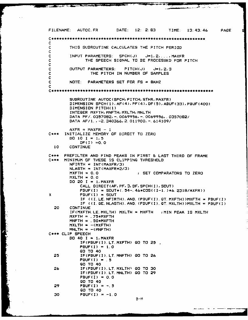
FILENAME: AUTOC.FR DATE: 12: 2:83 TIME: 13:43:46 PAGE
C************************************************************CC THIS SUBROUTINE CALCULATES THE PITCH PERIODCC INPUT PARAMETERS: SPCH(J) J=12, ... ,MAXFRC THE SPEECH SIGNAL TO BE PROCESSED FOR PITCHCC OUTPUT PARAMETERS: PITCH(J) J=1,2,3C THE PITCH IN NUMBER OF SAMPLESCC NOTE: PARAMETERS SET FOR FS - 8KHZCC***************************************************************
SUBROUTINE AUTOC(SPCHPITCHSTHRMAXFR)DIMENSION SPCH(1),AF(4),PF(4),DF(5),ABUF(33),PBUF(400)DIMENSION PITCH(l)INTEGER MXFTHMNFTHoMXLTHoMNLTHDATA PF/.0357082,-.0069956,-.0069956,.0357082/DATA AF/1.,-2.340366,2.011900,-.614109/
AXFR = MAXFR - 1C*** INITIALIZE MEMORY OF DIRECT TO ZERO
DO 10 I = 1,5DF(I) =0.0
10 CONTINUE
C*** PREFILTER AND FIND PEAKS IN FIRST & LAST THIRD OF FRAMEC*** MINIMUM OF THESE IS CLIPPING THRESHOLD
NFIRTH = INT(MAXFR/3)NLASTH = INT(MAXFR*2/3)MXFTH = 0.0 ; SET COMPARATORS TO ZEROMXLTH = 0.0DO 20 I = 1,MAXFR
CALL DIRECT(AF, PFo3DFSPCH(I),SOUT)PBUF(I) = SOUT*(.54-.46*COS((I-1. )*6.2318/AXFR))
x PBUF(I) = SOUTIF ((I.LE.NFIRTH).AND. (PBUF(I).GT.MXFTH))MXFTH = PBUF(I)IF ((I.GE.NLASTH).AND. (PBUF(I).GT.MXLTH))MXLTH = PBUF(I)
20 CONTINUEIF(MXFTH.LE.MXLTH) MXLTH = MXFTH ;MIN PEAK IS MXLTHMXFTH = .75*MXFTHMNFTH = .50*MXFTHMXLTH = -(MXFTH)MNLTH = -(MNFTH)
C*** CLIP SPEECHDO 40 I = 1,MAXFR
IF(PBUF(I).LT.MXFTH) GO TO 25PBUF(I) = 1.0GO TO 40
25 IF(PBUF(I).LT.MNFTH) GO TO 26PBUF(I) - .5GO TO 40
26 IF(PBUF(I).LT.MXLTHI GO TO 30IF(PBUF(I).LT.MNLTH) GO TO 29PBUF(I) = 0.0GO TO 40
29 PBUF(I) = -. 5GO TO 40
30 PBUF(I) = -1.0
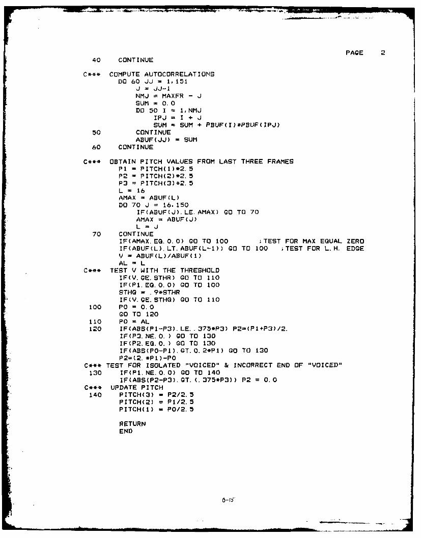
PAGE 240 CONTINUE
C*** COMPUTE AUTOCORRELATIONSDO 60 JJ = 1, 151
J = JJ-INMJ = MAXFR - JSUM =0. 0DO 50 1 =1.NMJ
IPJ = I + JSUM -SUM + PBUF(I)*PflUF(IPJ)
50 CONTINUEABUF(JJ) = SUM
60 CONTINUE
C*** OBTAIN PITCH VALUES FROM LAST THREE FRAMESP1 PITCH(1)*2.5P2 = PITCH(2)*2. 5P3 =PITCH(3)*2. 5L = 16AMAX = AI3UF(L)DO 70 ,J = 16, 150
IF(ABUF(J).LE.AMAX) GO TO 70AMAX = AI3UF(J)L= J
70 CONTINUEIF(AMAX. EQ. 0. 0) GO TO 100 ;TEST FOR MAX EQUAL ZEROIF(ABUF(L).LT.ABUF(L-1)) GO TO 100 ;TEST FOR L.H. EDGEV =AI3UF(L)/ABUF(l)
AL =L
C*** TEST V WITH THE THRESHOLDIF(V. GE. STHR) GO TO 110IF(Pl. EQ.0. 0) GO TO 100STHO = . 9*STHRIF(V. GE. STHQ) GO TO 110
100 Po = 0.0GO TO 120
110 PO0=AL120 IF(ABS(Pl-P3).LE. .375*P3) P2-(Pl+P3)/2.
IF(P3. NE.0. ) GO TO 130IF(P2. EQ. 0. ) GO TO 130IF(ABS(PO-PI).GT.0.2*Pl) GO TO 130P2=(2. *Pl)-PO
C*** TEST FOR ISOLATED "VOICED" & INCORRECT END OF "VOICED"130 IF(P1. NE. 0. 0) GO TO 140
IF(ABS(P2-P3).GT.(.375*P3)) P2 =0.0
C*** UPDATE PITCH140 PITCH(3) - P2/2.5
PITCH(2) = P1/2. 5PITCH(1) = P0/2.5
RETURNEND

FILENAME: DIRECT.FR DATE: 12: 2:83 TIME: 13:44:38 PAGE
CC THIS ROUTINE IMPLEMENTS THE DIRECT FORM FILTER.CC **-****-**,*-************-****-**-**-**-*********** * ,H*l**** I(
SUBROUTINE DIRECT(A, P, M, D, XIN, XOUT)
DIMENSION A(1),P(1)oD(1)
XOUT =. 0D(1) = XIN
DO 10 J = 1, MI = M + 1 -JXOUT = XOUT + D(I+1)*P(I+1)D(1) =D(1) - A(I+1)*D(I+I)D(I+I) = D(I)
10 CONTINUEXOUT = XOUT + D(1)*P(1)RETURNEND
.- y.
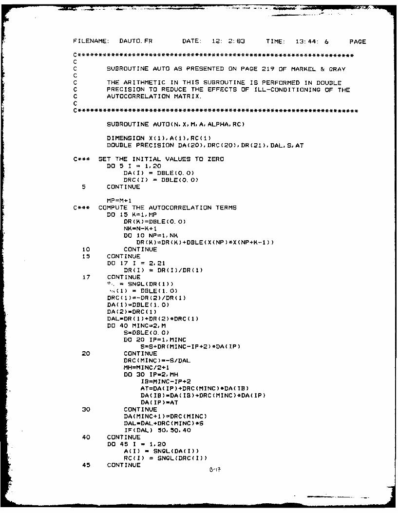
- ~ ~ ~ - ,- - _
FILENAME. DAUTO.FR DATE: 12: 2:63 TIME: 13:44: 6 PAGE
CC SUBROUTINE AUTO AS PRESENTED ON PAGE 219 OF MARKEL & GRAYCC THE ARITHMETIC IN THIS SUBROUTINE IS PERFORMED IN DOUBLEC PRECISION TO REDUCE THE EFFECTS OF ILL-CONDITIONING OF THEC AUTOCORRELATION MATRIX.C
SUBROUTINE AUTO(N, X,M, A,ALPHA, RC)
DIMENSION X(1),A(1),RC(1)DOUBLE PRECISION DA(20),DRC(20),DR(21),DAL,S,AT
C*** SET THE INITIAL VALUES TO ZERODO 5 I = 1,20
DA(I) =DBLE(O.0)DRC4I) =DI3LE(0.0)
5 CONTINUE
MP=M+1C*** COMPUTE THE AUTOCORRELATION TERMS
DO 15 K=1,MPDR(K)=DBLE(O. 0)NK=N-K+ 1DO 10 NP=1,NK
DR ( 4) =DR (K)+DBLE( X (NP )*X(NP +K-1))10 CONTINUE15 CONTINUE
DO 17 I = 2,21DR(I) = DR(I)/DR(1)
17 CONTINUE-SNGL(DR(l))
4()= DJ3LE(1. 0)DRC( 1)=-DR(2)/DR( 1)DA(1)=DBLE(1. 0)DA(2)=DRC( 1)DAL=DR( 1)+DR(2)*DRC( 1)DO 40 MINC=2,M
S=DBLE(0. 0)DO 20 IP=1,MINC
S=S+DR(MINC-IP+2)*DA( IP)20 CONTINUE
DRC(MINC)=-S/DALMH=MINC/2+1DO 30 IP=2,MH
11=MINC-IP+2AT=DA( IP)+DRC(MINC)*DA( IB)DA( IB)=DA( IB)+DRC(MINC)*DA(IP)DA( IP )=AT
30 CONTINUEDA(MINC+1 )=DRC(MINC)DAL=DAL+DRC (MINC ) *IF(DAL) 50,50,40
40 CONTINUEDO 45 I1 1,20
A(I) =SNGL(DA(I))RC(I) = SNGL(DRC(l))
45 CONTINUE

PAGE 2ALPHA = SNGL(DAL)ALPHA = SQRT(ALPHA*RO)
50 RETURNEND
11A38 0 IMPLEMENTING LPC ( NEAR PREDICTIVE CODING) ALGORITHMS 22IN THESTUDY OF SP..U AIR FORCE ND OF TECHWRIGHT-PATTERSON AFB ON SCHOOL OF ERGI. C E MCKOWN
UNCLA F ED DEC R3 AFTGE/EE/830 4,5 F/G 8/4 N
EhIEEEEEEE
mhEhE ~ ~ E

1.0 ~ E1.811111.!.25.
MICROCOPY RESOLUIION TLSI CHART
NATtoNA[ ~ l(R AU OF ! IANI AIU Ht IA
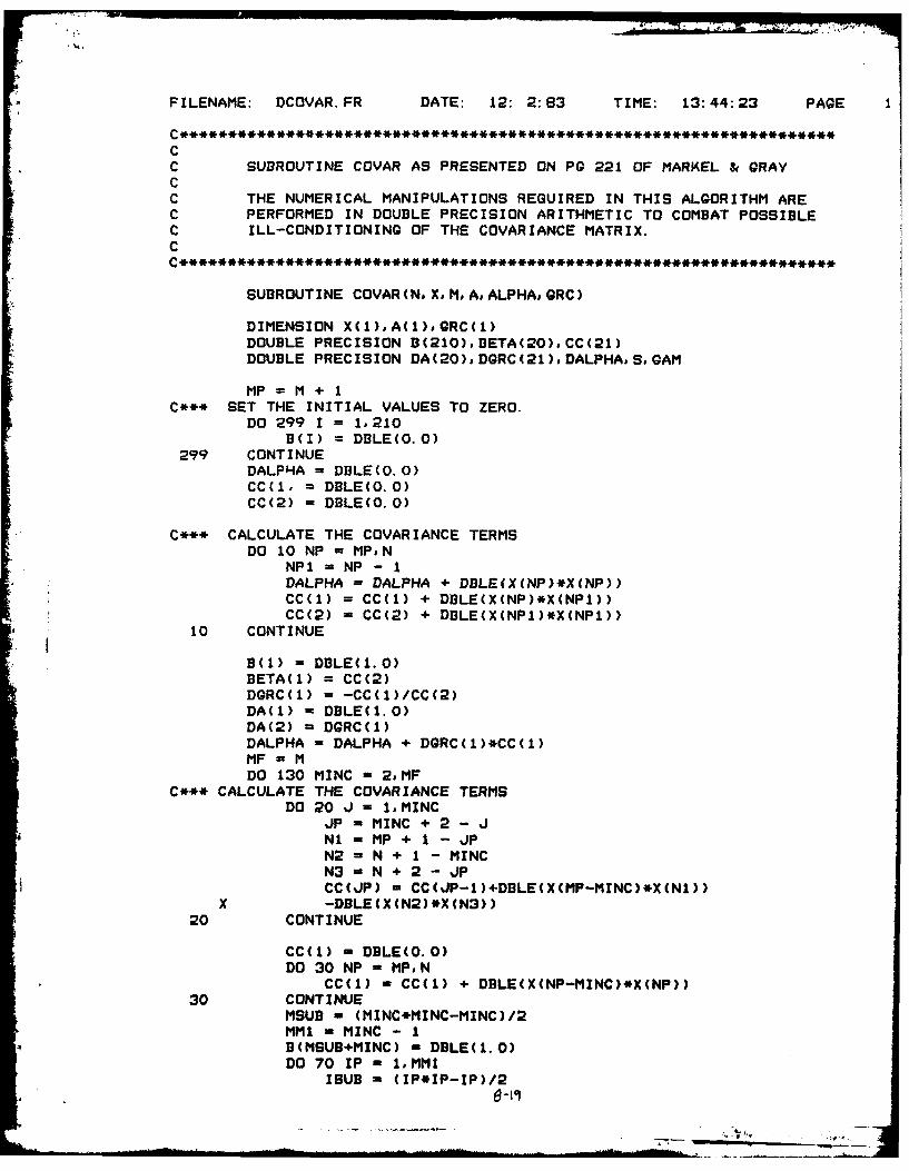
FILENAME: DCOVAR.FR DATE: 12: 2:83 TIME: 13:44:23 PAGE
CC SUBROUTINE COVAR AS PRESENTED ON PG 221 OF MARKEL & GRAYCC THE NUMERICAL MANIPULATIONS REQUIRED IN THIS ALGORITHM AREC PERFORMED IN DOUBLE PRECISION ARITHMETIC TO COMBAT POSSIBLEC ILL-CONDITIONING OF THE COVARIANCE MATRIX.C
SUBROUTINE COVAR(N#XoMA, ALPHA, GRC)
DIMENSION X(1),A(1)oGRC(1)DOUBLE PRECISION B(210),BETA(20),CC(21)DOUBLE PRECISION DA(20),DGRC(21),DALPHASoGAM
MP = M + IC*** SET THE INITIAL VALUES TO ZERO.
DO 299 I = 1,210B(I) = DBLE(O.O)
299 CONTINUEDALPHA = DBLE(O.0)CC(1, = DBLE(O.O)CC(2) = DBLE(O.0)
C*** CALCULATE THE COVARIANCE TERMSDO 10 NP - MP°N
NP1 = NP - 1DALPHA = DALPHA + DBLEIX(NP)*X(NP))CC(1) = CC(1) + DBLE(X(NP)*X(NP1))CC(2) = CC(2) + DSLE(X(NP1)*X(NP1))
10 CONTINUE
B(1) = DBLE(1.0)BETA(l) = CC(2)DGRC(1) = -CC(1)/CC(2)DA(1) = DBLE(1.0)DA(2) = DGRC(1)DALPHA = DALPHA + DGRC(1)*CC(1)MF - MDO 130 MINC - 2.MF
C*** CALCULATE THE COVARZANCE TERMSDO 20 J = 1,MINC
JP m MINC + 2 - JNi = MP + 1 - JPN2 = N + I - MINCN3 N + 2 - JPCC(JP) - CC(JP-1)+DBLE(X(MP-MINC)*X(N1))
X -DBLE(X(N2)*X(N3))20 CONTINUE
CC(1) - DBLE(O.0)DO 30 NP MPN
CC(1) - CC(1) + DBLE(X(NP-MINC)*X(NP))30 CONTINUE
MSUB - (MINC*MINC-MINC)/2MM1 - MINC - 1B(MSUB+MINC) = DBLE(1.0)DO 70 IP - I°MM1
ISUB - (IP*IP-IP)/2B -1

PAGE 2IF (IETA(IP)) 140,70,40
40 GAM -DBLE(0.0)DO 50 J 1, IP
GAM = AM+CC(J+1)*B(ISUB+J)50 CONTINUE
GAM = GAM/BETA(IP)DO 60 JP = 1, IP
B (MSUB+JP ) =8(MSUB+JP )-GAM*B (ISUB+JP)60 CONTINUE70 CONTINUE
BETA(MINC) - DBLE(0.0)DO 80 J = 1,MINC
BETA(MINC) - BETA(MINC)+CC(J+1)*B(MSUB+J)so CONTINUE
IF (BETA(MINC)) 140, 120,9090 S = DBLE(O.0)
DO 100 IP - 1,MINCS = S + CC(IP)*DA(IP)
100 CONTINUEDGRC(MINC) -- S/BETA(MINC)DO 110 IP =2,MINC
M2 = MSUB + IP - IDA(IP) = DA(IP) + DGRC(MINC)*B(M2)
110 CONTINUEDA(MINC+1) = DGRC(MINC)
120 CONTINUES - DGRC(MINC)*DGRC(MINC)*3ETA(MINC)DALPHA - DALPHA - SIF (DALPHA) 140, 140, 130
130 CONTINUE
140 CONTINUEDO 150 1 = l,MP
A(I) = SNGL(DA(l))QRC(I) = SNGL(DQRC(I))
150 CONTINUEALPHA =SNQL(SQRT(DALPHA))RETURNEND

FILENAME: VOCODE.FR DATE: 12: 2:83 TIME: 13:45: 4 PAGE
pcC
C PROGRAM: VOCODE.C AUTHOR: CRAIG MCKOWNC DATE: 24 AUG 83 - 30 SEP 83CC FUNCTION: USES THE OUTPUT OF "PREDICT" (THE LPC CODER) TOC PRODUCE OUTPUT SPEECH. THIS IS A VOCODER.CC LOAD LINE: RLDR VOCODE IOF UNVOCD DRAND GLOT1 GLOT2 GLOT3C THROAT @FLIBe
C
C
C PARAM: FILE FROM WHI'CH LPC DATA IS READC DUMMY: A DUMMY FILE, NOT USEDC RUMMY: FILE TO WHICH NORMALIZED VOCODED SPEECH IS WRITTENC AR: LPC COEFFICIENTS - AR(1) IN THIS PROGRAM IS THE SAMEC AS AR(2) IN THE CODER PROGRAM.C U: OUTPUT OF "UNVOCD" OR "VOICED" - AN INPUT TO "THROAT"C W: MEMORY FOR "THROAT"C S: OUTPUT OF "THROAT" - VOCODED SPEECHC INTS: ARRAY WITH INTEGER VALUES OF SC X: INTEGER ARRAY USED FOR WRBLKC POLES: THE NUMBER OF POLES OF THE OUTPUT FILTER.C VOCD: FLAG WHICH DENOTES VOICED/UNVOICED DECISION FROM CODERC PIT: PITCH INFORMATION (PITCH PERIOD IN SAMPLES)C IX: DOUBLE PRECISION SEED NUMBER FOR SUBROUTINE "UNVOCD"C
INTEGER SPEEFL(7),PARAM(7),DUMMY(7)oRUMMY(7)oMAIN(7)INTEGER POLES,P1oX(256),VOCDoPITINTS(200)DIMENSION U(250)oAR(20),W(0:20)oS(250)DOUBLE PRECISION IX
DATA VALF, NPTS°N6,N5/0.0,000/DATA IS, IP.KS.KEND/1,0,00/IX - DBLE(203)
NDONE - 0NFILES - 4CALL IOF(NFILES, MAIN SPEEFL, DUMMY, PARAM, RUMMY, MS, S1, S2, S3, S4)CALL DFILW(RUMMYoIER)IF(IER.EG. 13) GO TO 40IF(IER.NE. 1) TYPE " DELETE FILE ERROR "PIER
40 CALL CFILW(RUMMY,3o8#IER)IF (IER.NE.1) TYPE " CREATE FILE ERROR ", IERCALL OPEN(4, RUMMY, 3.IER)IF(IER.NE. 1) TYPE " OPEN FILE ERROR "PIERCALL OPEN(3,PARAM,3, IER)IF(IER. NE. 1) TYPE " OPEN FILE ERROR "PIER
C*** READ OVERALL PAREMETERS FOR VOCODING OF SPEECHREAD BINARY(3) POLES, NEMP°UNGA, NGLT
C********************************************************************-C*** SYNTHESIZE ONE EVARIABLE LENGTH3 FRAME OF SPEECH
100 CONTINUEC*** READ FRAME PARAMETERS
READ BINARY(3,END-1001) VOCD.P1,PITAL0 -21
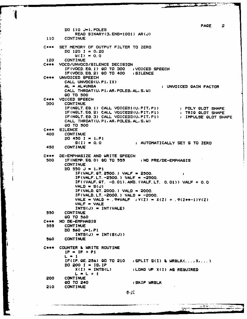
PAGE 2DO 110 J-1,POLES
READ DINARY(3,END=1001) AR(J)110 CONTINUE
C*** SET MEMORY OF OUTPUT FILTER TO ZERODO 120 1 0,20
W(I) =0. 0120 CONTINUE
C*** VOCD/UNVOCD/SILENCE DECISIONVIF(VOCD.EQ.l) GO TO 300 ;VOICED SPEECHIF(VOCD. EQ. 2) 0O TO 400 ;SILENCE
C*** UNVOICED SPEECHCALL UNVOCD(U.Pi. IX)AL - AL*UNGA £UNVOICED GAIN FACTORCALL THROAT(U, P1.AR. POLES, AL, S. )GO TO 500
C*** VOICED SPEECH300 CONTINUE
IF(NGLT.EQ.l) CALL VOICED1(UPIT,Pl) ; POLY CLOT SHAPEIF(NGLT.EQ.2) CALL VOICED2(U,PIT,PI) ; TRIG CLOT SHAPEIF(NQLT. EQ.3) CALL VOICED3(U,PIT,P1) ;IMPULSE CLOT SHAPECALL THROAT(U. P1.AR. POLES, AL.S. )GO TO 500
C*** SILENCE400 CONTINUE
DO 450 1 - 1.Pl5(I) - 0.0 ;AUTOMATICALLY SET S TO ZERO
450 CONTINUE
C*** DE-EMPHASIZE AND WRITE SPEECH500 IF(NEIP. EQ. 0) GO TO 555 ;NO PRE/DE-EMPHASIS
CONTINUEDO 550 J - 1.PI
IF(VALF. OT. 2500.) VALF -2500.£IF(VALF.LT. -2500.) VALF -- 2500.IF((VALF.QT. -0.01).AND. (VALF.LT. 0.01)) VALF =0.0
VALD - S(J)IF(VALD. OT. 2000.) VALD u2000.IF(VALD. LT. -2000.) VALD -- 2000.VALE - VALD + .9*VALF iY(Z) - X(Z) + .9(Z**-l)Y(Z)VALF - VALEINTS(J) - INT(VALE)
550 CONTINUEGO TO 560
C*** NO DE-EMPHASIS555 CONTINUE
DO 560 Jin*lINTS(J) - INT(9(J))
560 CONTINUE
C*** COUNTER & WRITE ROUTINEIP -IP + P1LIF(IP. GE. 256) GO TO 210 ;SPLIT S(1) & WRBLK(... 4. ...)DO 200 1 - IS. IP
X(I) - INTS(L) ;LOAD UP X(I) AS REQUIREDL -L+ 1
200 CONTINUEGO TO 240 ;SKIP WRDLK
210 CONTINUE
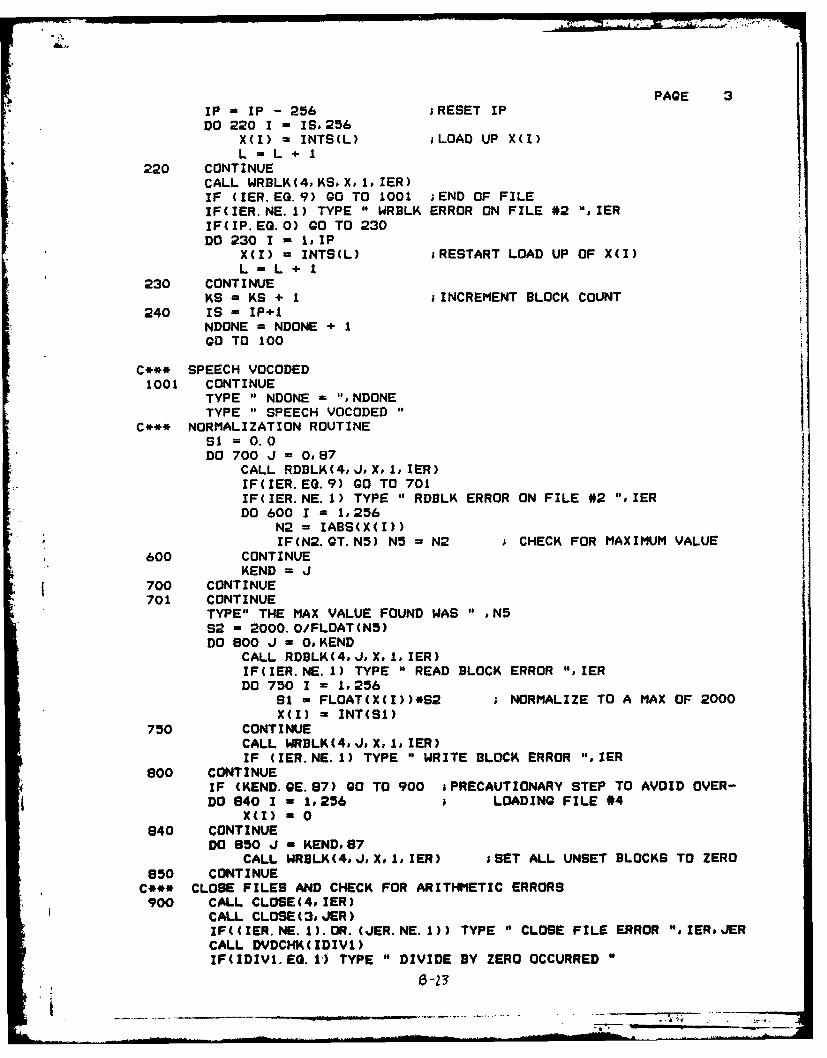
PAGE 3
IP = IP - 256 ;RESET IP
DO 220 I - IS, 256X(I) = INTS(L) ;LOAD UP X(I)L=L+ I
220 CONTINUECALL WRBLK(4, KS, X, 1.IER)IF (IER. EG. 9) GO TO 1001 ;END OF FILEIF(IER.NE.1) TYPE " WRBLK ERROR ON FILE #2 ",IERIF(IP. EQ.0) GO TO 230DO 230 I - 1,IP
X(I) - INTS(L) ;RESTART LOAD UP OF X(I)L-L+ I
230 CONTINUEKS - KS + 1 ;INCREMENT BLOCK COUNT
240 IS = IP+1NDONE = NDONE + 1GO TO 100
C*** SPEECH VOCODED1001 CONTINUE
TYPE " NDONE = ",NDONETYPE " SPEECH VOCODED
C*** NORMALIZATION ROUTINESi =0.0DO 700 J = 0,87
CALL RDBLK(4., XI., IER)IF(IER. EQ. 9) GO TO 701IF(IER.NE.1) TYPE " RDBLK ERROR ON FILE #2 ",IERDO 600 I = 1,256
N2 = IABS(X(I))S IF(N2.GT.NS) N5 = N2 CHECK FOR MAXIMUM VALUE
600 CONTINUEKEND = J
700 CONTINUE701 CONTINUE
TYPE" THE MAX VALUE FOUND WAS " ,N5S2 = 2000. 0/FLOAT(NS)DO 800 J - 0,KEND
CALL RDBLK(4,J,XI, IER)IF(IER.NE.1) TYPE " READ BLOCK ERROR ",IERDO 750 1 = 1,256
S - FLOAT(X(I))*S2 NORMALIZE TO A MAX OF 2000X(I) - INT(SI)
750 CONTINUECALL WRBLK(4,JXI,1IER)IF (IER.NE.1) TYPE " WRITE BLOCK ERROR ",IER
800 CONTINUEIF (KEND. GE. 97) GO TO 900 sPRECAUTIONARY STEP TO AVOID OVER-DO 840 I 1,256 LOADING FILE #4
X(I) = 0
840 CONTINUEDO 850 J - KEND,87
CALL WRBLK(4,J,X1,.IER) jSET ALL UNSET BLOCKS TO ZERO850 CONTINUE
C*** CLOSE FILES AND CHECK FOR ARITHMETIC ERRORS900 CALL CLOSE(4,IER)
CALL CLOSE(3,JER)IF((IER.NE.1).OR.(JER.NE.1)) TYPE " CLOSE FILE ERROR ",IERJERCALL DVDCHK(IDIV1)IF(IDIV1.EQ.I") TYPE " DIVIDE BY ZERO OCCURRED "
'~
-= . .. il _ ,i .. . . . . -. . . . . . . . . - - i II I - l a ... .

CALL OVERFL( IFLOI) PGIF (IFLOl.EG.l) TYPE " OVERFLOW OCCURREDIF (IFLOl. EQ. 3) TYPE " UNDERPLOW OCCURRED"
STOPEND

FILENAME: UNVOCD.FR DATE: 12: 2:83 TIME: 13:46:25 PAGE
CC THIS SUBROUTINE CREATES A NORMAL RANDOM SEQUENCE WHICH WILLC BE A RANDOM NOISE INPUT TO THROAT. THE OUTPUT OF THISC PROGRAM IS AN ARRAY, U(I), OF LENGTH AS DETERMINED IN THEC CALLING ROUTINE.CC NOTE: THIS MUST BE LINKED TOGETHER WITH DRAND.CC PARAMETERS: U(I) : OUTPUT SEQUENCEC FRMSIZ : LENGTH OF ARRAYC IX : DOUBLE PRECISION SEED TO THIS ROUTINEC A NEW IX IS GENERATED BY THE PROGRAMC TO FEED THE NEXT ITERATION.C DRAND(IX): A DOUBLE PRECISION FUNCTION -C GENERATES UNIFORM PDF.CC **************** **** **** ****** ********************
SUBROUTINE UNVOCD(UFRMSIZ, IX)
DOUBLE PRECISION U1,V,W,T, X,EoE2oEIOE3, ZP,P1,F,P2,P3,P4oP5,PIX ,PI2,A1,A2,A3,A4,A5,A6,A7,A8,A9,AIO,A12,A13,A14,A15°A16,A17,A18
DOUBLE PRECISION INTEGER IXINTEGER FRMSIZDIMENSION U(1)DATA Al/.884070402298758DO/o
X A2/1. 131131635444180DO/oX A3/. 96655477086949DO/,X A4/.958720824790463DO/,X AS/.630834801921960DO/,X A6/.755591531667601DO/,X A7/. 034240503750111DO/,
X AS/.911312780288703DO/,X A9/.479727404222441DO/,X AIO/1.10547366102207DO/,X A12/.872834976671790DO/,X A13/.049264496373128DO/oX A14/.5955071380159401D0/,X A15/.80557792442317DO/.X A16/.053377549506886DO/,X A17/.973310954173898DO/,X E/2.216035867166471DO/,X A1B/. 10025191068563DO/,
C*** CALCULATE THE NORMAL FUNCTIONPI - 3.1415926536D0P12 - (PI*2.0)**(-.5)E2 - E**2.0E3 - E2/2.0DO 2200 N - 1,FRMSIZ
UI - DRAND(IX)IF(U1 .GT.Al)GO TO 1000V = DRAND(IX)X - E * (A2 * U1 + V - 1)GO TO 9000
1000 IF(U1 .LT. A17)QO TO 12001005 V - DRAND(IX)
W - DRAND(IX)T - E3 - DLOG(W)

PAGE 2* E10 = T * V**2
IF(E10 .GT. E3)GO TO 1005IF(UI .LT. A3)GO TO 1010X = -(2.0 * T)**.5GO TO 9000
1010 X - (2.0 * T)**.5GO TO 9000
1200 IF(UI .LT. A4)GO TO 15001300 V - DRAND(IX)
W -DRAND(IX)
T =E -A5 * DMINI(VW)P -DMAXI(V,W)IF(P .LT. A6)GO TO 1800Pt A7 * DABSCZ)F =P12*DEXP(-T*T/2. 0)-Al8*(E-DABS(T))IF(PI .LE. F)QO TO 1600GO TO 1300
1500 IF(UI .LE. AB)GO TO 17001600 V = DRAND(IX)
W = DRAND(IX)
T -A9 + A10 * DtIINI(VW)P2 - DMAX1(V,W)IF(P2 .LE. A12)GO TO 1600P3 -A13 *DABS(Z)
F -P12 *DEXP(-T*T/2.0)-A18*(E-DABS(T))
IF(P3 .LE. F)GO TO 1800* GO TO 1600
1700 V - DRAND(IX)W = DRAND(IX)Z-V-W
* jT =A9 -A14 * DMIN1(V,W)P4 =DMAX1(V,W)IF(P4 .LE. A15)GO TO 1800P5 - A16 * DABS(Z)F - P12 * DEXP(-T*T/2.0)-A18*(E-DABS(T))IF(P5 .LE. F)QO TO 1800GO TO 1700
1800 IF(Z .LT. 0.0)00 TO 1900X - -TGO TO 9000
1900 X -T9000 CONTINUE
U(N) - SNGL(X2200 CONTINUE
IF(FRMSIZ. GE. 200) GO TO 2400DO 2300 1 FRMSIZ+1# 200
U(I) -0.0
2300 CONTINUE2400 RETURN
END

FILENAME: DRAND.FR DATE: 12: 2:e3 TIME: 13:48: 6 PAGE
CC THIS FUNCTION IS A UNIFORM RANDOM NUMBER GENERATOR.C
DOUBLE PRECISION FUNCTION DRAND(IX)DOUBLE PRECISION INTEGER IXAP.B15.B165XHI 5XALO.LEFTLO,FHIKDATA A/1&607D0/. B15/3276BD0/. Bl6/65536D0/. P/2147483647D0/XHI - IX/B16XHI - XHI -DMOD(XHI, IDO)XALO = (IX- XHI * B16) * ALEFTLO -XALO/1116LEFTLO = LEFTLO - DMOD(LEFTLO. iDO)I FHI -XHI * A + LEFTLOK = FHI/B15K = K - DMOD(K1 iDO)
IX = (((XALO-LEFTL0*916)-P) +- (FHI-K*Bl5)*B16)+K
IF(IX.LT.O.DOe IX= X
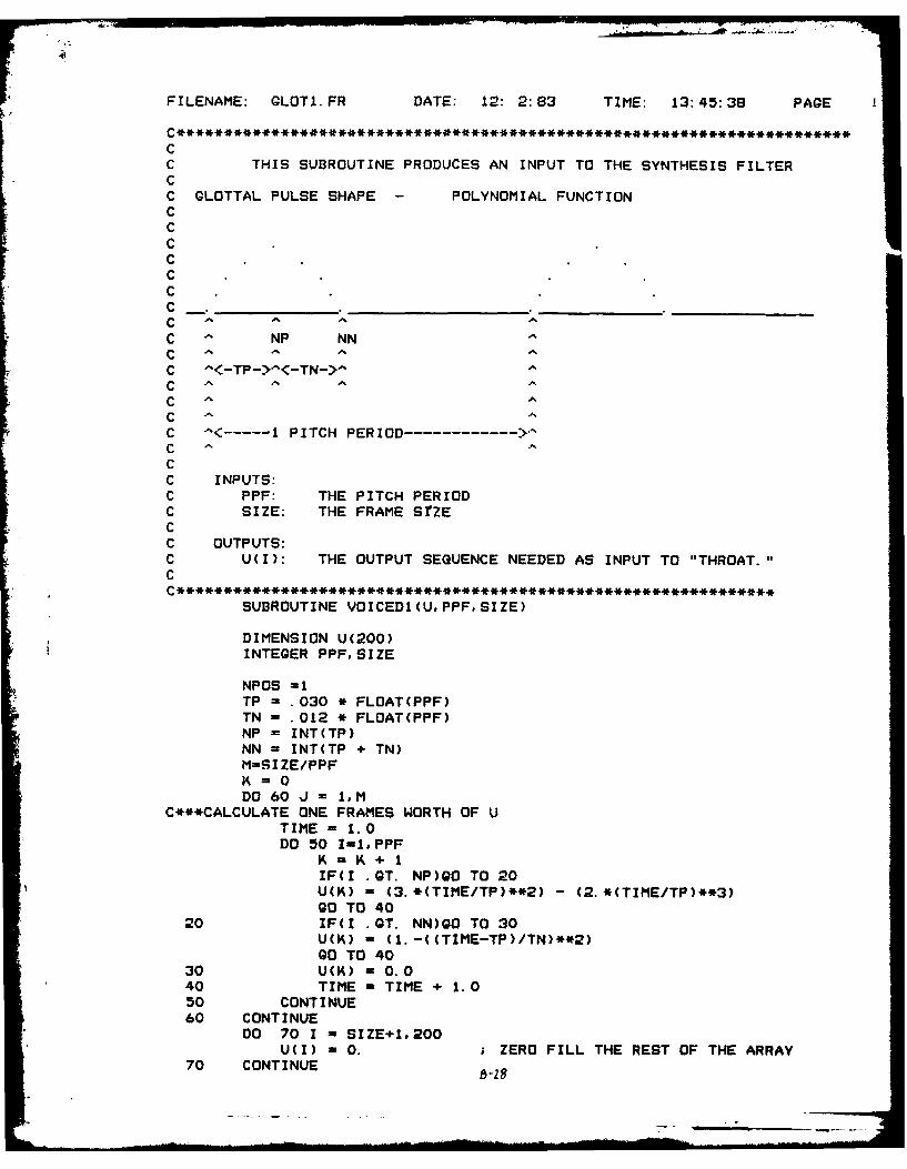
*FILENAME: GLOTI.FR DATE: 12: 2:83 TIME: 13:45:38 PAGE
CC THIS SUBROUTINE PRODUCES AN INPUT TO THE SYNTHESIS FILTERCC GLOTTAL PULSE SHAPE - POLYNOMIAL FUNCTIONCCCCCCC _ _ _ _ _ _ _ _ _ _ _ _ _ _ _ _ _ _ _
CC NP NN
C ^<-TP->^<-TN->^CCCC ^<-------1I PITCH PERIOD------------- >
CCC INPUTS:C PPF: THE PITCH PERIODC SIZE: THE FRAME StZECC OUTPUTS:C UCI): THE OUTPUT SEQUENCE NEEDED AS INPUT TO "THROAT."C
SUBROUTINE VOICEDI (U. PPF, SIZE)
DIMENSION U(200)INTEGER PPF, SIZE
NPOS =1TP = .030 * FLOAT(PPF)TN - . 012 * FLOAT(PPF)NP - INT(TP)NN = INT(TP + TN)M=SI ZE/PPF
DO 60 J - 1,MC***CALCULATE ONE FRAMES WORTH OF U
TIME - 1.0DO 50 I-I. PPF
K - K+ IIF(I GQT. NP)QO TO 20U(K) - (3. *(TIME/TP)**2) -(2. *(TIME/TP)**3)GO TO 40
20 IF(I GQT. NN)QO TO 30U(K) - (1. -((TIME-TP)/TN)**2)GO TO 40
30 U(K) -0.040 TIME - TIME + 1.050 CONTINUE80 CONTINUE
DO 70 I - SIZE+1.200U(I) - 0. ZERO FILL THE REST OF THE ARRAY
70 CONTINUE ~2

PAGE 2RETURNEND
b -.30

FILENAME: GLOT2.FR DATE: 12. 2.:63 TIME: 13:45:50 PAGE
c THIS SUB3ROUTINE PRODUCES AN INPUT TO THE SYNTHESIS FILTERCC GLOTTAL PULSE SHAPE -TRIGONOMETRIC
CCC
C
C NP NN
CC -'<-P-><-T->
C
C -'<------1 PITCH PERIOD ------------ >CC INPUTS:C PPF: THE PITCH PERIODC SIZE: THE FRAME SIZECC OUTPUTS:C U(I): THE OUTPUT SEQUENCE NEEDED AS INPUT TO "THROAT."C
SUBROUTINE VOICED2(U. PPF, SIZE)
DIMENSION U(200)
INTEGER PPF, SIZE
PI= 3. 14159P12 =PI/2.0
NPOS =1TP = .030 * FLOAT(PPF)TN = . 012 * FLOAT(PPF)NP = INT(TP)NN = INT(TP + TN)M -SIZE/PPF ;NUMBER OF PITCH PERIODS PER FRAMEK 0DO 60 J = 1,M
C*** CALCULATE ONE FRAME OF U(I)TIME = 1.0DO 50 1 = 1,PPF
K= K+ 1IF(I .GT. NP)GO TO 20U(K) - (.5)*(1.0-COB(TIME*PI/TP))GO TO 40
20 IF(I .GT. NN)QO TO 30U(K) - (.5)*CDS(((TIME-TP)/TN)*PI2)GO TO 40
30 U(K) = 0.040 TIME=-TIME +1.050 CONTINUE80 CONTINUE
DO 70 1 SIZE+1, 200U(I) =0.0
70 CONTINUE

PAGE 2RETURNEND

FILENAME: GLOT3.FR DATE: 12: 2:833 TIME: 13:46: 4 PAGE
CC THIS SUBROUTINE PRODUCES AN INPUT TD THE SYNTHESIS FILTERCC GLOTTAL PULSE SHAPE IMPULSE (TP=1,TN=O)CCCCCC
C
C A NP NN
CC A .P-><-T->
C
CC
C INPUTS:C PPF: THE PITCH PERIODC SIZE: THE FRAME SIZECC OUTPUTS:C U(I): THE OUTPUT-SEQUENCE NEEDED AS INPUT TO "THROAT."~C
SUBROUTINE VOICED3(U. PPF, SIZE)
DIMENSION U(200)INTEGER PPF, SIZE
TIME - 1.0G = 1.0U(1) =GNPF2 PPF+2DO 400 A 2,PPF
U(K) -0.0400 CONTINUE
U(PPF+l) = GDO 500 A - NPF2, SIZE
U(K) -0.0500 CONTINUE
RETURNEND
Ll- 33
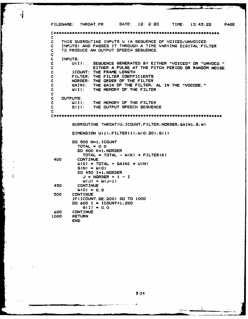
FILENAME: THROAT.FR DATE: 12: 2:83 TIME: 13:45:22 PAGE
C **********************************************************
CC THIS SUBROUTINE INPUTS U (A SEQUENCE OF VOICED/UNVOICEDC INPUTS) AND PASSES IT THROUGH A TIME VARYING DIGITAL FILTERC TO PRODUCE AN OUTPUT SPEECH SEQUENCE.CC INPUTS:C U(I): SEQUENCE GENERATED BY EITHER "VOICED" OR "UNVOCD."C EITHER A PULSE AT THE PITCH PERIOD OR RANDOM NOISE.C ICOUNT: THE FRAME LENGTHC FILTER: THE FILTER COEFFICIENTSC NORDER: THE ORDER OF THE FILTERC GAINI: THE GAIN OF THE FILTER, AL IN THE "VOCODE."C W(I): THE MEMORY OF THE FILTERCC OUTPUTS:C W(I): THE MEMORY OF THE FILTERC S(I): THE OUTPUT SPEECH SEQUENCEC
SUBROUTINE THROAT(U, ICOUNT,FILTERNORDER,GAINIS,W)
DIMENSION U(1),FILTER(1),W(0:20),S(1)
DO 500 N=1, ICOUNTTOTAL = 0.0DO 400 K=1,NORDER
TOTAL = TOTAL - W(K) * FILTER(K)
400 CONTINUEW(O) = TOTAL + GAIN1 * U(N)S(N) = W(O)DO 450 I=INORDER
J = NORDER + 1 - IW(J) = W(J-1)
450 CONTINUEW(O) = 0.0
500 CONTINUEIF(ICOUNT. GE. 200) GO TO 1000DO 600 I = ICOUNT+1.200
S(I) - 0.0600 CONTINUE1000 RETURN
END
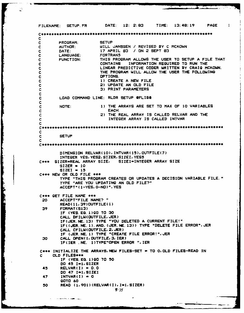
FILENAME: SETUP.FR DATE: 12: 2:83 TIME: 13:46:19 PAGE
CC PROGRAM: SETUPC AUTHOR: WILL JANSSEN / REVISED BY C MCKOWN
C DATE: 17 APRIL 83 / ON 2 SEPT 83
C LANGUAGE: FORTRAN5
C FUNCTION: THIS PROGRAM ALLOWS THE USER TO SETUP A FILE THAT
C CONTAINS INFORMATION REQUIRED TO RUN THE
C LINEAR PREDICTIVE CODER WRITTEN BY CRAIG MCKOWN.
C THE PROGRAM WILL ALLOW THE USER THE FOLLOWING
C OPTIONS.C 1) CREATE A NEW FILE
C 2) UPDATE AN OLD FILEC 3) PRINT PARAMETERSCC LOAD COMMAND LINE: RLDR SETUP OFLIBt
CC NOTE: 1) THE ARRAYS ARE SET TO MAX OF 10 VARIABLES
C EACH.
C 2) THE REAL ARRAY IS CALLED RELVAR AND THE
C INTEGER ARRAY IS CALLED INTVAR
C
CC SETUPC
DIMENSION RELVAR(10),INTVAR(15),OUTFILE(7)INTEGER YES, YES2, SIZER, SIZEI, YES5
C*** SIZER-REAL ARRAY SIZE, SIZEI-INTEGER ARRAY SIZESIZER - 10SIZEI - 15
C*** NEW OR OLD FILE ***TYPE "THIS PROGRAM CREATES OR UPDATES A DECISION VARIABLE FILE."
TYPE "ARE YOU UPDATING AN OLD FILE?"ACCEPT"(1-YES, O-NO)",YES
C*** GET FILE NAME ***
20 ACCEPT"FILE NAME? "
READ(11,39)OUTFILE(1)39 FORMAT(S13)
IF (YES. EQ. 1)GO TO 30CALL DFILW(OUTFILE, JER)IF(JER.NE. 13) TYPE "YOU DELETED A CURRENT FILE!"IF((JER. NE. 1).AND. (JER. NE. 13)) TYPE "DELETE FILE ERROR",JERCALL CFILW(OUTFILEo2, JER)IF (JER.NE.1) TYPE "CREATE FILE ERROR!"oJER
30 CALL OPEN(1,OUTFILE,3,ZER)IF(IER .NE. 1)TYPE"OPEN ERROR ",IER
C*** INITIALIZE THE ARRAYSNEW FILES-SET - TO O,OLD FILES-READ IN
C OLD FILES***IF (YES.EG.1)QO TO 50
DO 45 I-IoSIZER45 RELVAR(I) - 0.0
DO 47 I-I.SIZEI47 INTVAR(I) - 0
GOTO 6050 READ (1,901)(RELVAR(I),I-I,SIZER)
I i, ° i I i I I I I I - 35 ..

KPAGE 2READ (1,902)(INTVAR(I), I-1,SIZEI)
C*** UPDATE ARRAYS**60 CONTINUE
TYPE" (CR>X IF YOU CHOOSE TO CHANGE A VARIABLE ENTER Y V CR>X OTHERWISE ENTER ANOTHER LETTER (CR>
TYPE *
TYPE"CURRENT VALUE OF ACCEPT/NOT ACCEPT (A-0,NA-1): ".INTVAR(1)TYPE "CHANGE VALUE? "o
CALL RCHAR(ICHAR. lER)IF(ICHAR.NE.89)GO TO 5000
ACCEPT" (CR> INPUT NEW VALUE :"I.INTYAR (1)
I00 TETYPE"CURRENT NUMBER OF POLES IS :". INTVAR(2)TYPE"CHANGE VALUE? "
CALL RCHAR(ICHAR. IER)
IF(ICHAR. NE. 89)00 TO 5001
ACCEPT" (CR> INPUT NEW VALUE: ". INTVAR(2)
5001 TYPE so"TYPE"THE METHOD OF PREDICTION IS"TYPE"(AUTDO,COVAR-i): ". INTVAR(3)TYPE "CHANGE VALUE?"CALL RCHAR(ICHAR. IER)IF(ICHAR. NE. 89)00 TO 5002ACCEPT"<CR> INPUT NEW VALUE: ",INTVAR(3)
5002 TYPE " "1
TYPE"CURRENT VALUE:NO. OF POINTS/SET (MAXFR): ",INTVAR(4)TYPE"CHANGE VALUE? "
CALL RCHAR(ICHAR. IER)IF(ICHAR. NE. 89)00 TO 5003ACCEPT"CCR> INPUT NEW VALUE: ". INTVAR(4)
5003 TYPE 11"TYPE"THE CURRENT VALUE OF FILTER SPACINGS IS (MAXPT): ",INTYAR(5)TYPE"CHANGE VALUE? "t
CALL RCHAR(ICHARIER)IF(ICHAR. NE. 89)00 TO 5004ACCEPT"<CR> INPUT NEW VALUE: ". INTVAR(5)
5004 TYPE " "TYPE"THE CURRENT VALUE OF PRE/DE-EMP (1-Y#0-N) IS: ",INTVAR(6)TYPE"CHANGE VALUE? "s
CALL RCHAR(ICHARIER)IF(ICHAR. NE. 89)00 TO 5005ACCEPT"(CR> INPUT NEW VALUE: ", INTVAR(6)
5005 TYPE " "o
TYPE"THE CURRENT VALUE OF GLOTTAL SHAPE IS"TYPE"(1-POLYNOMIAL. 3-IMPULSE) :". INTVAR(7)TYPE"CHANGE VALUE?"CALL RCHAR(ICHARIER)IF(ICHAR. NE. 99)00 TO 5008ACCEPT"(CR> INPUT NEW VALUE: ". INTVAR(7)
5006 TYPE""

PAGE 3TYPE"THE CURRENT VALUE OF HAMMING WINDOW (0-NO.1-YES): ",INTVAR(B)TYPE' CHANGE VALUE? of
CALL RCHAR(ICHAR. IER)IF(ICHAR. NE. 89)00 TO 5007
* . ACCEPT"<CR> INPUT NEW VALUE: ', INTYAR(S)
5007 TYPE totTYPE'THE METHOD OF PITCH DETECTION ISTYPE"(SIFT-0,AUTOC-1): '$ INTVAR(9)TYPE"CHANGE VALUE? af
CALL RCHAR(ICHAR. IER)IF(ICHAR.NE.89)GO TO 5008ACCEPT"<CR> INPUT NEW VALUE: % INTVAR(9)
5008 TYPE to~TYPE"PITCH DET'N AND COEF. CAL'N FROM SAME FILE?"TYPE"CURRENT VALUE (1-Y, 0-N): ". INTVAR( 10)TYPE'CHANGE VALUE?CALL RCHAR(ICHAR, IER)IF(ICHAR. NE. 89)00 TO 5010ACCEPT"'ZCR> INPUT NEW VALUE: ",INTVAR(10)
5010 TYPE to toTYPE mt THE CURRENT VALUE OF VOICED/UN THRESH IS: 1,RELVAR(1)TYPE"CHANGE VALUE? asCALL RCHAR(ICHAR. IER)IF(ICHAR. NE. 89)00 TO 5011ACCEPT"<CR> INPUT NEW REAL VALUE: '%RELVAR(1)
5011 TYPE is aoTYPE"CURRENT VALUE OF SPEECH SCALE-(IN CODER): ",RELVAR(2)TYPE"CHANGE VALUE? it
CALL RCHAR(ICHAR, IER)IF(ICHAR.NE.89)GO TO 5015ACCEPT"(<CR> INPUT NEW REAL VALUE: ",RELVAR(2)
5015 TYPE to maTYPEaSCURRENT VALUE OF SILENCE THRESH-(IN ENER)IS: ".RELVAR(3)TYPE"aCHANGE VALUE? IsCALL RCHAR(ICHAR. IER)IF(ICHAR. NE. 89)00 TO 5016ACCEPT"'ZCR> INPUT NEW REAL VALUE: ".RELVAR(3)
5016 TYPE aa maTYPEaaCURRENT VALUE OF UNVOICED GAIN FACTOR IS: ",RELVAR(4)TYPEaCHANGE VALUE? tCALL RCHAR(ICHARIER)IF(ICHAR. NE. 99)00 TO 5020ACCEPT"<CR> INPUT NEW REAL VALUE: %,RELVAR(4)
5020 CONTINUE
C*** TYPE ARRAY *1
TYPENTHE ARRAYS HAVE BEEN LOADED"ACCEPT"DO YOU WANT TO HAVE THE ARRAY TYPED(1-YES. 0-NO): ",YESIF(YES EQ. 0)00 TO 200TYPE" ACCEPT/NOT ACCEPT: ",INTVAR(1)TYPE" NUMBER OF POLES: a ZNTVAR(2)TYPE" METHOD (0-AUTO, 1-COVAR9 ): "*INTVAR (3)TYPE" MAXFR: ma INTVAR(4)
B-37

PAGE 4TYPE" MAXPT: ", INTYAR(5)TYPE" PRE/DE-EMP (1-Y, 0-N): ", INTVAR(6)TYPE" CLOT (1-POLYNOMIAL. 3-IMPULSE): ", INTVAR(7)TYPE" HAMMING WINDOW? (1-Y.O-N): ",INTVAR(8)TYPE" METHOD PITCH DET (0-SIFTo1-AUTOC): "#INTVAR(9)TYPE" PITCH & COEF'S SAME FILE(1-Y,O-N): ",INTVAR(10)TYPE"VOICED/UN THRESHOLD: ". RELVAR( 1)TYPE"SPEECH SCALE-( IN CODER): ". RELVAR(2)TYPE"SILENCE THRESHOLD ", RELVAR(3)TYPE"UNVOICED GAIN FACTOR ". RELVAR(4)
C*** OUTPUT FILE ***
200 TYPE "WRITE DECISION VARIABLES TO SAME FILE?"ACCEPT "(1-YES,0-NO): ".,YES2IF (YES2 .EQ. 1)GO TO 75CALL CLOSE(1.IER)IF (IER .NE. 1)TYPE"CLOSE FILE ERRORI ",IERACCEPT"FILE NAME?"READ( 11, 69)OUTFILE( 1)
69 FORMAT(S13)CALL DFILW(OUTFILE, JER)IF(JER.EQ. 13) TYPE "YOU DELETED A CURRENT FILE!"IF((JER. NE. 1). AND. (JER. NE. 13)) TYPE "DELETE FILE ERROR",JERCALL CFILW(OUTFILE, 2.JER)IF (JER.NE.1) TYPE "CREATE FILE ERROR!".JER
70 CALL OPEN(1,OUTFILE.3,IER)IF(IER .NE. 1)TYPE"OPEN ERROR ".IER
75 CALL REWIND(l)WRITE (1,901)(RELVAR(I).I=1,SIZER)
* WRITE (1, 902)(INTVAR(l), 11.SIZEI)CALL CLOSE(1,IER)IF (IER .NE. I)TYPE"CLOSE FILE ERROR2 ".IERACCEPT"PRINT ARRAY ON PRINTRONICS?( 1-Y, 0-N) ", YESIF(YES .EQ. 0)GO TO 1001WRITE(12. 1499)OUTFILE(l)CALL FQDAY(IMON. IDAY. IYEAR)CALL FGTIME(IHOUR. IMIN, ISEC)WRITE (12. 1311)IDAY. IMON. IYEARWRITE (12. 1312)IHOUR, IMIN. ISEC
1311 FORMAT("0", "DATE I . X, 12, "1/". 12, 1" 12)1312 FORMAT("0", "TIME : .IX, 12, :" 12, "".12)
WRITE(12. 1500)INTVAR(1)WRITE(12. 1501)INTVAR(2)WRITE(12. 1502)INTYAR(3)WRITE(12. 1503)INTYAR(4)WRITE(12. 1504)INTVAR(5)WRITE(12. 1505)INTVAR(6)WRITE(12. 1506)INTVAR(7)WRITE( 12. 1507)INTVAR(S)WRITEC 12, 1508)INTVAR(9)WRITE(12. 1509)INTVAR(10)WRITE(12. 1600)RELVAR(1)WRITE(12. 1601)RELYAR(2)WRITE( 12. 1602)RELVAR(3)WRITE( 12, 1603)RELVAR(4)
1499 FORMAT(1XS13)1500 FORMAT("O"," ACCEPT/NOT ACCEPT "016)1 501 FORMAT ("0"," NUMBER OF POLES ",I&6)1502 FORMAT( "0"." METHOD (0-AUTO. 1-COVAR) Ns16)
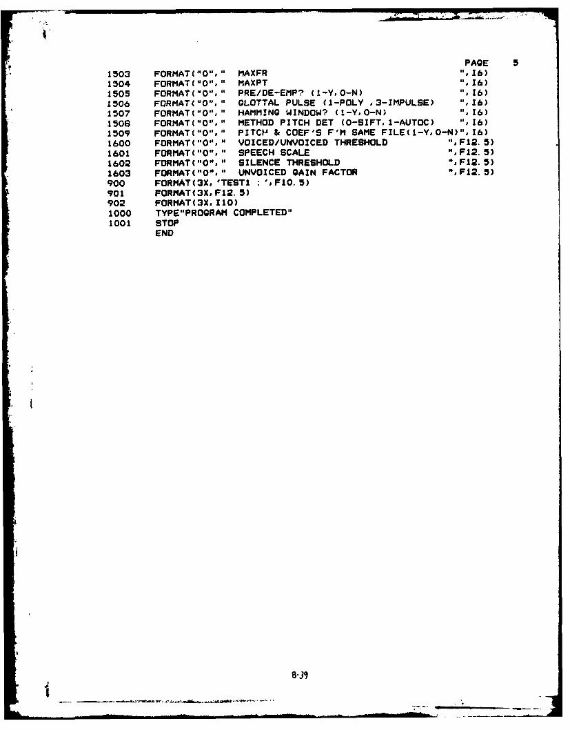
PAGE 51503 FORMAT("O'%" MAXFR ",16)1504 FORMAT('""" MAXPT ",16)1505 FORMAT("O"."* PRE/DE-EMP? (1-Y. 0-N) ",16)1506 FORMAT("O"." GLOTTAL PULSE (1-POLY .3-IMPULSE) ",16)1507 FORMAT("0'." HAMMING WINDOW? (1-Y#0-N) ",16)1508 FORMAT("O"." METHOD PITCH DET (0-SIFT. 1-AUTOC) ",16)1509 FORMAT("O"," PITCH & COEF'S F'M SAME FILE(1-Y*0-N)". 16)1600 FORMAT("0"," VOICED/UNVOICED THRESHOLD "*F12.5)1601 FORMAT ("0'%" SPEECH SCALE ",F12. 5)1602 FORMAT("0'%" SILENCE THRESHOLD ",F12.5)1603 FORMAT("O"," UNVOICED GAIN FACTOR ",F12.5)900 FORMAT(3X.'TESTI :'j.FIO.5)901 FORMAT(3XF12. 5)902 FORMAT(3X. 110)1000 TYPE"PROGRAM COMPLETED"1001 STOP
END
8-39
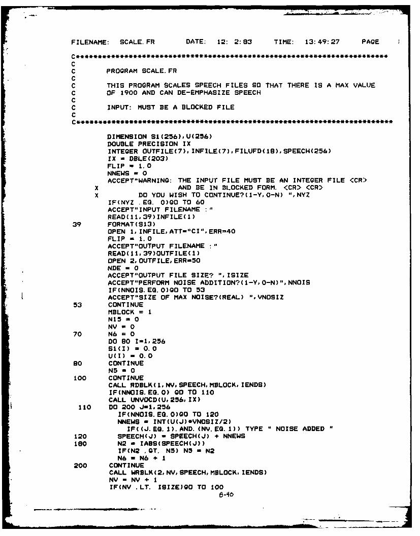
FILENAME: SCALE.FR DATE: 12: 2:183 TIME: 13:49:27 PAGE
CC PROGRAM SCALE. FRCC THIS PROGRAM SCALES SPEECH FILES SO THAT THERE IS A MAX VALUEC OF 1900 AND CAN DE-EMPHASIZE SPEECHCC INPUT: MUST BE A BLOCKED FILEC
DIMENSION 91(256). U(256)DOUBLE PRECISION IXINTEGER OUTFILE(7). INFILE(7),FILUFD(IB),SPEECH(256)IX - DBLE(203)FLIP -1.0NNEWS -0ACCEPT"WARNING: THE INPUT FILE MUST BE AN INTEGER FILE <CR>
X AND BE IN BLOCKED FORM. (CR> (CR>X DO YOU WISH TO CONTINUE?(1-Y,0-N) ",NYZ
IF(NYZ .EQ. 0)G0 TO 60ACCEPT"INPUT FILENAME :
READ( 11.39) INFILE( 1)39 FORMAT(S13)
OPEN 1. INFILE.ATT-"CI".ERR=40FLIP = 1.0ACCEPT"OUTPUT FILENAME :
READ( 11. 39)OUTFILE( 1)OPEN 2. OUTFILE. ERRM5ONDE - 0ACCEPT"OUTPUT FILE SIZE? '. ISIZEACCEPT"PERFORM NOISE ADDITION?( 1-Ye 0-N)", NNOIS
U IF(NNOIS.EQ.0)GO TO 53* I ACCEPT"SIZE OF MAX NOISE?(REAL) ".VNOSIZ
53 CONTINUEMBLOCK = 1N15 0NV -0
70 N6 -0DO 80 1-1, 256SI(I) - 0.0UCI) - 0.0
s0 CONTINUEN5 - 0
100 CONTINUECALL RDBLK (1,*NV. SPEECH, MBLOCK. lENDS)IF(NNOIS. EQ. 0) GO TO 110CALL UNVOCD(U. 256. IX)
110 DO 200 J-1. 256IF(NNOIS. EQ. 0)00 TO 120NNEWS - INT(U(J)*VNOSIZ/2)
IF((J.EQ.1).AND. (NV.EQ. 1)) TYPE "NOISE ADDED'120 SPEECH(.J) - SPEECH(J) + NNEWS160 N2 - IABS(SPEECH(J))
IF(N2 GQT. N5) N5 - N2N6 - N6 + 1
200 CONTINUECALL WRBLK(2. NV. SPEECH. MBLOCRD lENDS)NV - NV + 1IF(NV .LT. ISIZEIQO TO 100

PAGE 2
500 TYPE"THE FOLLOWING NO. OF POINTS WHERE CHECKED ",N6TYPE"AND THE MAX. VALUE FOUND WAS ",N5S2 = 1900.0 / FLOAT(N5) * FLIPN6 = 0NV = 0
600 CALL RDBLK(2, NV, SPEECH, MBLOCK, IENDS)DO 700 J=1,256
Sl(J) = FLOAT(SPEECH(J)) * S2SPEECH(J) = INT(SI(J))
700 CONTINUECALL WRBLK(2, NV, SPEECH, MBLOCK, IER)N6 = N6 + 1NV = NV + IIF(NV .LT. ISIZE)GO TO 600
900 CONTINUEN15 = N6 * 256TYPE"THE FOLLOWING NO. OF POINTS WERE OUTPUT ",N15CALL CLOSE(1,IER)IF(IER .NE. 1)TYPE"CLOSE ERROR ON INPUT ", IERCALL CLOSE(2oIER)IF(IER NE. 1)TYPE"CLOSE ERROR ON OUTPUT ",IERTYPE"BLOCKS PROCESSED: ",N6GO TO 60
50 TYPE"OPEN ERROR ON OUTPUTGO TO 60
40 TYPE"OPEN ERROR ON INPUT "60 STOP
END
__ _ _ _ _

FILENAME: TSTRND.FR DATE: 12: 2:83 TIME: 13: 56: 0 PAGE
CC LOAD LINE:RLDR TSTRND DRAND UNVOCD PLOT1O PLOT5.LB
C GRPH. LB @FLIB@CC THIS PROGRAM RUNS EITHER THE UNIFORM OR NORMAL GENERATORC AND PROVIDES A PLOT(PRINTRONIX OR TEKTRONIX) AND/OR THE
C MEAN AND VARIANCE.C
DIMENSION IT(500),U(256),T(500),XHOR(128),YVER(128),W(256)DOUBLE PRECISION INTEGER IXINTEGER FRMSIZ, NAMEI(7),NAME2(7)ACCEPT"HOW 4ANY 256 POINT SETS? ",NUM
NUFRM = NUM * 256IX = DBLE(203)DO 50 I = 1,256
U(I) = DBLE(O.0)W(I) = DBLE(O.0)
50 CONTINUEDO 100 I=1,500
IT(I) = 0
100 CONTINUEICOUNT = 0SUM1 = 0.0SUM2 = 0.0K=0ACCEPT"CHOOSE RANDOM GENERATOR(I-NORMAL, O-UNIFORM) ",NORM
IF(NORM .EQ. 1)GO TO 1200DO 1000 NTIM=I,NUM
DO 900 MTIM = 1,128ICOUNT = 2 + ICOUNTPEMP = SNGL(DRAND(IX))TEMP = PEMP * 500.SUMI = SUMI + TEMP
SUM2 = SUM2 + (TEMP)**2ITEMP = INT(TEMP)IF((ITEMP .GT. 500).OR. (ITEMP .LT. 0))GO TO 600
XHOR(MTIM) = TEMPIT(ITEMP) = IT(ITEMP) + 1GO TO 800
600 TYPE"DATA EXCEEDS BOUNDARY AT ",ITEMP
BOO PEMP - SNGL(DRAND(IX))TEMP - PEMP * 500.SUMI = SUMI + TEMPSUM2 = SUM2 + (TEMP)**2ITEMP - INT(TEMP)IF((ITEMP.GT. 500).OR. (ITEMP. LT.0)) GO TO 850YVER(MTIM) - TEMP
IT(ITEMP) - IT(ITEMP) + 1GO TO 900
850 TYPE " DATA EXCEEDS BOUNDARY AT ",ITEMP900 CONTINUE
IF ((IER. NE. 1).OR. (JER. NE. 1)) TYPE " WRBLK ERROR "&IER, JERK-K+ I
1000 CONTINUETYPE "PRODUCED UNIFORM DISTRIBUTIONGO TO 5000

PAGE 2
1200 FRMSIZ =256
DO 3000 NTIM1,.NUMCALL UNVOCD(U,FRMSIZ, IX)CALL UNVOCD(W.FRMSIZ. IX)DO 2500 NR=1,256
ITEMP = INT(U(NR) * 80.0)
ITEMP = ITEMP + 250 ;CENTERING FOR PLOTSIF((ITEMP .GT. 500).DR. (ITEMP .LE. 0))GO TO 1400SUMI - SUMI + FLOAT(ITEMP)SUM2 - SUM2 +FLOAT(ITEMP)**2XHOR(NR) -ITEMPIT(ITEMP) =IT(ITEMP) + 1ICOUNT - ICOUNT + 1GO TO 1600
1400 CONTINUE1600 ITEMP - INT(W(NR) * 80.0)
ITEMP - ITEMP + 250 ; CENTERING FOR PLOTSIF((ITEMP GOT. 500).OR. (ITEMP. LT. 0)) GO TO 2000
SUMI - SUMI + FLOAT(ITEMP)SUM2 - SUM2 +FLOAT(ITEMP)**2IT(ITEMP) = IT(ITEMP) + I
ICOUNT = ICDUNT + IGO TO 2500
2000 CONTINUE2500 CONTINUE
K=-K + 13000 CONTINUE
TYPE "PRODUCED NORMAL DISTRIBUTION5000 CONTINUE
DO 4000 A 1,500T(K) =FLOAT(IT(K))
4000 CONTINUEXMEAN = SUMI/ICOUNTXMEAN2 = XMEAN**2VAR = SUM2/ICOUNT - XMEAN2TYPE "VAR = ",VARSTDEV - SQRT(VAR)
ACCEPT"DO YOU WANT A PLOT?(1-Y#0-N) ",NYESIF(NYES.NE.1) GO TO 5600ACCEPT"USE PRINTRONICS PLOTTER?( 1-Y, 0-N) ". NOIF(NO. EQ. 0) GO TO 5500NP - ISF - 1.0NPTS - 500CALL PLOT1O(T, NPTSI NP, XO, YO, SF)NP - 10CALL PLOT1O(Te NPTS. NP XO, YO, SF)GO TO 5600
5500 IFSCL - 0MODE - 0NG IN -500CALL GRPH2("DENSITY". NO. T.U.N. MODE. YM. YA.IFSCL)
5600 CONTINUETYPE "MEAN -",XMEAN," STDEY ",STDEV
STOPEND
G-3

APPENDIX C
Waveshapes of the Speech Signalzs
C-1
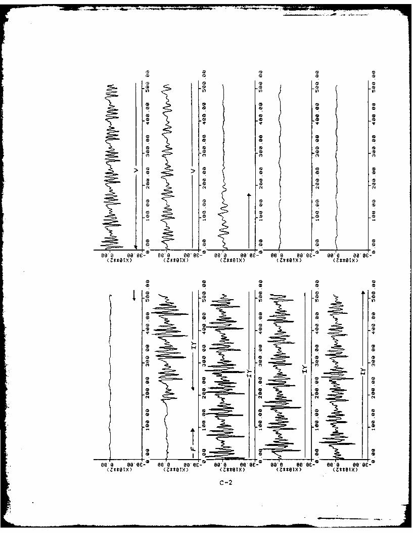
43C 43S3 443~~ Q34 34
CD ID CD a)-C I3 43 CD 43
inD Cninin
43~C 034 34CD to43434
43-03 34
M C4)
43m W343N3 04 NN
co434
00 0 c> 1 1 0 c- o*a o*ec 0' 0 G - z* 8*oc43 43OI 43OI 43OI **
43 43C4
h) in V) t
CD Q3 034
C3 W3
43 43 Q34CD 43
CD CD~
C3D3 = 4 34C3 4 3 34
4343434
00 3 9A e 1 0- i' 0" 0 E' 0" 003 43- 09-8 00 43-43el 43ol 43*BX (43OIX 43o~
c-2 I z.
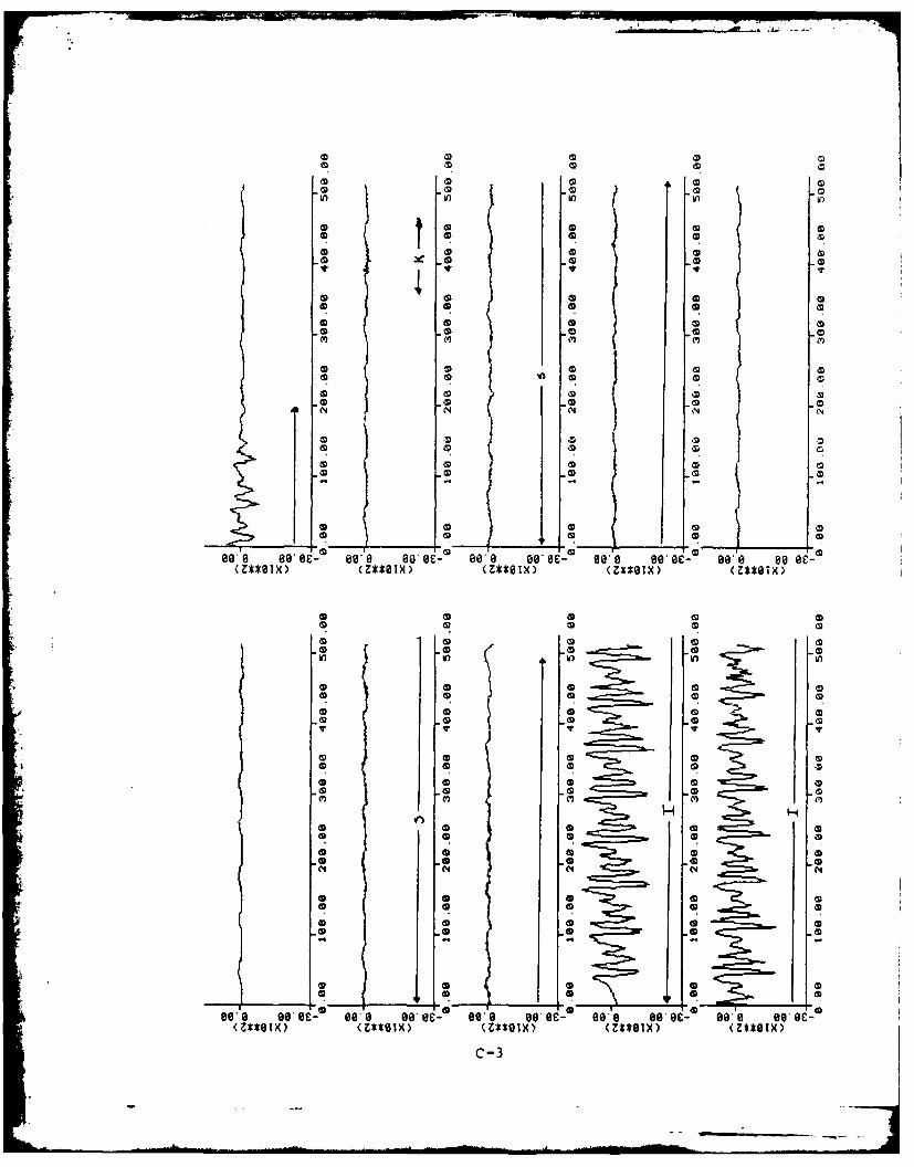
10 3
CD C 3
3 3 3 3W
o 3 0 C
m V)1 1
IDI 3 G3) 3 3p
*- -(D0
Be N Be eiN0*o 0' 0a 0'B- O O g.e- 90 B e
3 Z*OX (Z*O3 (Z*I 3 (*@
3D 3 D3D CD3&
3 CD3
V) V3 In
3 3D
30 1'33 -0
~ In I InCD
Be a 3e 0( - 008B- W e 0e B ee3ZSOX 3Ztox 3Z*OX (Z*OX 3Z*
3 3 3c-3
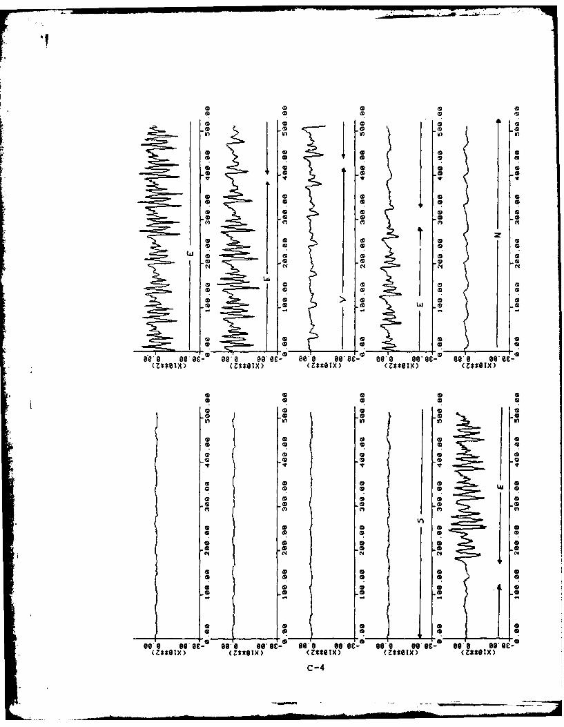
*In
0 0 0 a
0 0 0 alv
la w
00
0c 0 0 0 -0
00 0
Be 'a go e es B E 80 B 0 08a g0 i, e, e e
W 0 a 0 0
0 0D 0 0.
0 ID 00
0 N 0
WGo
00J O- B' 00- 9, W e ss W e 09 W e0Z*Gx 0Z*OX 0Z*OX 0Z*GX 0Z*
0 0 0C-4
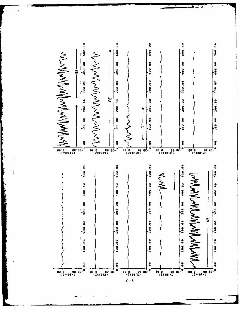
oD a C 0
W a go 0e 0e sB- e 8 e 0a 0'B- W o e(**OX 0Z~ox 0Z*OX 0Z*OX 07t
0 0 0 0
CD 0( 0D m
10* 0 0o e 0s 0 E 0 0 E eI s 0 sos g
0ZOX 0Z*OX 0Ztex 0Ztl)( O
10 0 0 0

In , Ann in
CD 0 D 6D a
0 00 (D4 (D 6a m
N N N
C'CD
Be a 60 6e sos a 6i, B o e e@ 0'B- 0
so' W e- s' e eP * 6 09 9 ,699 g r-, B.e g.e(Z**OTX)~C (Zt'I(**I)(*OT)(tex
C-6
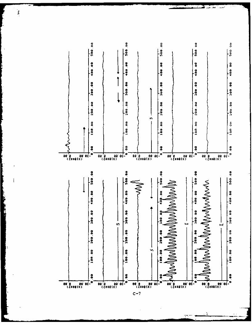
*9 .212 .
* .2 . .21.
* .2 .2 ' .2 .
*D 02. 2.
o Jpo 2 .2NnY ~1* 1
oAD 2.2.
oe s i, ss g-ei, 0. e E' g.o B 1. Be- 99. e . -*Z*OX (M l 2 .2*Ox .2tlx Z*G
* . 6 I * .C-7

6 96
4 1 6*
N 6 -6
V) ~ ~ ~ fL U n
oIn In in 6
6D Q
(
6Z~ox 6Z*@X 6Ztox 6so ( 0*IX
6 6 6 8

IC
Q)) mM
4j3.3.
IDC CD Q CDCD CD OD
11 -C, toI ~ 1
-0 0. 3
toI 0 0
(.A N C.4
910,0 .3*O .3~ s.3-a* s@ sos 0 e@ e~
*MIX .3*BX (Z*O3 (Z*O3
.3 .3 .9

in in I, t
* 0 0
I' "IS
IDS0
(~(4 (4IC
N' so Si- so-a s -e s s f B o-O. s ' wB,(Z*SelS SZ~l)(*OT)(sox
* S 5 510

* S S 0
* S S S S* 5 C ~ S *~ S
U, h~)
* 0 0 5
* 0 S S
o o S S
* 0 5 1~ It
o 50 5
* 0 0 S S
* S 0 S S
(I) (I) ~,
* 5 0 S S
*S S
S 5
S S
* S S S S
* S 5 S S
S S S S S
986 eeoc- eag eeoc- ore se ec- eee esee- 609 eeoc-
* 5 5 S S
S S S S S
S S S S S
* 0 5 5
Ifl U, IA
* S S
* S
o 5S
* S 5 S 00* S S S S
0 5S S S S(I)
k* 0 5* 0 S S* 0 5 5 0
* S S S S
* 0 0 5 S
* 5 0 S S
* 5 5 0 5- n - - -
* 0 0 0 S
* 6 0 5 5
* 5 0 5 5
eee eeoc- ore eeoc- see eeoc- see eeoc- see eeoc-c-il
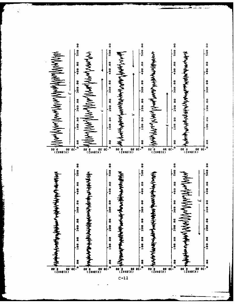
13 13 I 1ik 13
ID In 0 D
13 C 13 1D 11
11 13 1
*ID CD (D
CD3D IN1131
* * ~ In(D CD .0
Il ~AmC
hip1
Be's goBe' o- WBe ses B s-see0 0 a 0 Beeeese a-m
*(D C3D 13Inl. in In
1 3~ 13 1
13D 13131
13 13
ID 1_AD
so' go. 0i- 193 13 C* e.s g.e-, o@ sO 00 B13*Sx (Z*O3 13~ox 13OT 13*OX
o 13 13 c312

Now-
4D 01 0
10 (S)
o* 0S
N N
00A 80 see-, 80e eo*eO- Wee Be* e- osee ee ec-- 00.e 09*s-
*Z*OX <ZSOX (Z*S)(*OI)(*O
CDS
CD 14D
*D CDS
14 A N (
(Z**OTX) <Z0S) ZtlS ZSBX Z*GX
C -13

APPENDIX D
Code for Subroutine LATTICE
D-1

FILENAME: LATTICE.FR DATE: 12: 3:83 TIME: 14:47:38 PACE
C******************************************************************CC THIS SUBROUTINE CALCULATES THE PREDICTOR COEEFICIENTS
C BY THE LATTICE METHOD AS PRESENTED ON PP 411-416 OF
C RABINER & SCHAFER.C
SUBROUTINE LATTICE(N,X, POLESA, ALPHAK)
DIMENSION X(1),A(1)DOUBLE PRECISION B(0:400)oE(400),DA(20),DK(20),DAL,RODOUBLE PRECISION TEMPI, TEMP2, SUMI, SUM2, EMD2REAL K(1)INTEGER POLES
X CALL OVERFL(IFLO2)X IF(IFLO2.EQ.1) TYPE " OVERFLOW IN PREDICTX IF(IFLO2. EQ. 3) TYPE " UNDERFLOW IN PREDICT
DO 10 I = 1,POLESDA(I) = DBLE(O.O)DK(I) DBLE(O.O)
10 CONTINUEKNE = 1D2 = DBLE(2.0)DAL = DBLE(O.O)B(O) = DBLE(O.0)DO 20 I = 1,N
DAL = DAL + DBLE(X(I)*X(I))20 CONTINUE
X DAL = 1DODAL = DAL/1D04
X RO - DALDO 30 M = 1,N
E(M) = DBLE(X(M))B(M) = DBLE(X(M))
30 CONTINUESUMI = DBLE(O.0)SUM2 = DBLE(O.O)DO 40 M = 1,N
MI = M -1TEMPI = E(M)*B(MI)TEMP2 = (E(M)*E(M)) + (B(M1)*B(M1))
SUM1 = SUMI + TEMPISUM2 - SUM2 + TEMP2
40 CONTINUEDK(1) = D2*SUM1/SUM2IF(DABS(DK(1)).GT.DBLE(1. ))TYPE ' ERROR
x TYPE " DK(",KNE,") - ",DK(1)DA(1) DK(1)DO 200 1 2,POLES
I1= I - 1DO 50 M = 1,N
Ml = M- 1EM - E(M)E(M) - EM - DK(I1)*B(MI)B(M) - B(M1) - DK(I1)*EMIF(DABS(E(M)).LE. ID-15) E(M) - DBLE(O.0)IF(DABS(B(M)).LE. iD-15) B(M) = DBLE(O.0)
50 CONTINUE O-z

PAGE 2SUM1 = DBLE(0)SUM2 = DI3LE(O.0)DO 60 M = I,N
Ml = M - I
TEMPI = E(M)*13(MI)TEMP2 = (E(M)*E(M)) + (13(M1)*1(Ml))SUMI = SUMI + TEMPI1SUM2 = SUM2 + TEMP2
60 CONTINUEX CALL OVERFL(IFLO2)X IF(IFLD2.EQ.l) TYPE " OVERFLOW IN SUMX IF(IFLO2. EQ. 3) TYPE " UNDERFLOW IN SUM
DK(I) = 02*SUMI/SUM2IF(DABS(DK(I)). CT.I3BLE(1. ))TYPE ERROR
x TYPE DK(", I, ") =~ lDA(I) =DK(I)
DO 80 j = lullDA(J) = DA(J) -DK(I)*DA(I-J)
so CONTINUEx DAL = DAL - D1(I)*DK(I)*DAL200 CONTINUEX CALL OVERFL(IFLO)X IF(IFLO.EQ.l) TYPE " OVERFLOW IN LATTICEX IF(IFLO. EQ.3) TYPE " UNDERFLOW IN LATTICE
DO 250 M =1,N
Ml = M -1
E(M) = E(M) - DK(I1)*B(MI)IF(DABS(E(M)).LE.ID-20) E(M) =DBLE(O.0)
250 CONTINUEX DO0300 M I,NX DAL =DAL + E(M)*E(M)X300 CONTINUEX ALPHA = SNGL(SQRT(RO*DAL))
ALPHA = SNGL(SQRT(DAL))X TYPE " ALPHA = ",ALPHA
DO 100 I = 1,19IMJ = 21 - IA(IMJ) = -SNGL(DA(IMJ-1))I.YI) = SNGL(DK(I))
100 CONTINUEA(1I 1.0K(20) -SNGCDK(20))
X CALL OVERFL(IFLOI)X IF(IFLOI.EQ.1) TYPE " OVERFLOW IN ALPHAX IF(IFLOI. EQ. 3) TYPE " UNDERFLDW IN ALPHAX ACCEPT'CDNTINUE ON A NUMBER', IJKL
RETURNEND
o-3
VITA
Craig Eugene McKown was born on 23 May 1960 in Merced,
California. He is the son of Thomas E. and Evelyn L.
McKown. He attended high school in Bellevue, Nebraska and
graduated from Bellevue West High School in June of 1978.
He subsequently attended Washington University in St. Louis
with an Air Force ROTC scholarship and graduated with the
degree Bachelor of Science in Electrical Engineering in May
of 1982. One week after graduation and commissioning, Lt
McKown entered the Air Force Institute of Technology. He is
a member of Tau Beta Pi and Eta Kappa Nu engineering honor
societies. He is also a student member (81) of IEEE.
Permanent Address: 1600 Alcove Ct
Midland, TX 79703

!-NcTAqqTrrpSECURITY CLASSIFICATION OF THIS PAGE
REPORT DOCUMENTATION PAGEI& REPORT SECURITY CLASSIFICATION lb. RESTRICTIVE MARKINGS
2a SECURITY CLASSIFICATION AUTHORITY 3. DISTRIBUTION/AVAILABILITY OF REPORT
Approved for public release;2b. OECLASSI F ICATIONOOWNGRADING SCHEDULE distribution unlimited
4. PERFORMING ORGANIZATION REPORT NUMBER(S) 5. MONITORING ORGANIZATION REPORT NuMBER(S)
ArIT/G2/EE/83D-45
S. NAME OF PERFORMING ORGANIZATION b. OFFICE SYMBOL 7& NAME OF MONITORING ORGANIZATION
School of Engineering ArIT/E Y
6c. ADDRESS (City. State end ZIP CodIj 7b. ADORESS (City. State and ZIP Code)
Air Force Institute of Technology
'.!'right-Patterson AFB, 011 45433
go. NAME OF FUNDING/SPONSORING Eb. OFFICE SYMBOL 9. PROCUREMENT INSTRUMENT IDENTIFICATION NUMBERORGANIZATION (if applicable)
Bc. ADDRESS (City. State and ZIP Codal 10. SOURCE OF FUNDING NOS.
PROGRAM PROJECT TASK WORK UNITELEMENT NO. NO. NO. NO.
11. TITLE (Include Security Clasuufication)
See Box 19
12. PERSONAL AUTHOR(S)
Craig E. McKown, BSEE, 2LT, USA13& TYPE OF REPORT 13b. TIME COVERED 1.DATE OF REPORT s Yr. Mo.. Day) IS. PAGE COUNT
"S Thesis FROM TO 193 December16. SUPPLEMENTARY NOTATION
17. COSATI CODES IS. SUBJECT TERMS (Continua on rewrme it ,
FIELD GROUP SU OR. Linear Predictive Coding; Digital Speech Processing;.17 02
19. ABSTRACT (Continue on muvers if inecary and Identify by block numberl
Title: IM.LEMENTIN'G LPC ALGORITI'S IN THE STUDY OF SPEECH PROCESSING
Thesis Chairman: Larry Kizer, MNajor, USAF
20. OISTRISUTIONIAVAILABILITY OF ABSTRACT 21. ABSTRACT SECURITY CLASSIFICATION
UNCLASSIFIED/UNLIMITED Kj SAME AS RPT. 0 OTIC USERS [ UCLASSIFIED
122a. NAME OF RESPONSIBLE INDIVIDUAL 22b. TELEPHONE NUMBER 22c. OFFICE SYMBOL122 fliIetud A te Code)
[ Larry Kizer, !ajor, USAF (513)-255-3517 AFIT/E'Y
DO FORM 1473, 83 APR EDITION OF I JAN 73 IS OBSOLETE. UICLASSrTFDSECURITY CLASSIFICATION OF THIS PAGE
* . ,* .-*.-.-
SECURITY CLASSIFICATION OF THIS PAGE
This report describes a system which processes speech usinglinear predictive methods. The system is a software simulation ofan LPC analyzer and synthesizer. The system consists of two programs,one of which processes the speech to generate the LPC parameters,and another which processes these parameters to resynthesize thespeech. An important aspect of the system is that it enables the userto select from various pitch and coefficient analysis methods. Iialso allows the user to vary other parameters in order to simulate-other chan7es in the processing scheme.
To test the operation of the s.stci, a regAen of testin' -:as- erforieteL ''" var, in- the rnr.,
-Wichi t',e user has coi.trol. 7.:e z:ara. et,*:,. arc. dalc- t,-,e~iuvLriLU'lis iad eac'. .a - ~~:~-i ~~v-:e.?
5ystam -:erate( satisfactorily over all of the decision variahles.The flexibility ex;hibited by t]:e system in this te3ting indicatesthat the system can be a valuable tool for the study of linearpredictive coding of speech in the Signal Processing Laboratoryat the Air Force Institute of Technology.
SECURITY CLASSIFICATION OF THIS PAGE