a06a - english
TRANSCRIPT

7/21/2019 A06a - English
http://slidepdf.com/reader/full/a06a-english 1/8
CAD/CAM/CAE examples TÁMOP 4-1-2-08-2-A-KMR-2009-0029
1
CAD-CAM-CAE Examples
example title: Shaft type component (CAD)
example number: ÓE-A06a
example level: basic - medium - advanced
CAx system: CATIA v5
Related material part with TÁMOP CAD
Job Description: Create Cad model of a shaft type component in
CATIA v5.
1 The taskCreate a CAD models from the figure!
1.1 The solution steps
1.2 The preparation of hexagonal elements
The hex-head is the most difficult piece of work to model. First, we prepare this, then the
other elements from there to make up. As we all know the hex head is based on a hexagonal,each sides of hexagonal tangent same circuit, from there be drawn the following shape in a
Sketch plane.

7/21/2019 A06a - English
http://slidepdf.com/reader/full/a06a-english 2/8
CAD/CAM/CAE examples TÁMOP 4-1-2-08-2-A-KMR-2009-0029
2
First, place a 17mm diameter circle, this will be shown in the picture. Related command line
is placed around the circle with Profile command. We create Tangency constraint for
between all lines and the circle. The two points on the vertical axis of the recorded command
Coincidence, then we will all be parallel to the opposite side with Parallelism command. Give
that the two sides 120 degree angle to each other.
In the middle rounds were only needed to edit it so Right-click on Definition tab, tick theCircle object element Construction. Our editors will change to a line, but the constraints hold.
When you are finished you can click exit to exit the Workbench. You click the Pad
command and set the thickness of the "pull out" one body element.
1.3 The hex head rounded preparation
The hex head is not round off the edges. The round is along a circle. To this preparation, we
need the following Sketch.
We preparing in the plane, which coincides with the two opposite edges. Click this, and theSketch icon. A simple need to create a triangle whose sides fit the analogy of edges and the

7/21/2019 A06a - English
http://slidepdf.com/reader/full/a06a-english 3/8
CAD/CAM/CAE examples TÁMOP 4-1-2-08-2-A-KMR-2009-0029
3
longest side of the hypotenuse and an angle of 15 degrees. We know the bottom of distance
from the central axis is 8mm. Then fit to prepare the Coincidence command.
Then, we draw a vertical axis same distance from the centre ( Axis - ). That axis will be
reflected in the first triangle is drawn. Select the item to mirror, then click the Mirror
command . Finally, click on the mirror axis. If this is done and the picture looks like thisfigure step back to the 3D module with exit the Workbench command.
We select the Sketch and click the Groove command . First select the H-axis to choose
which line of the longitudinal axis of the hexagonal prism has been created. This set is madein the normal hexagonal head.

7/21/2019 A06a - English
http://slidepdf.com/reader/full/a06a-english 4/8
CAD/CAM/CAE examples TÁMOP 4-1-2-08-2-A-KMR-2009-0029
4
1.4 Preparation of the cylindrical elements
There is three cylinder sections of the piece. The left side of the drawing is Ø10 – 24mm long
section, the right side of the drawing is Ø8 and Ø10. Out of these parts is almost the same
way, therefore I present only one.
Click The finished hex head on one side, and opening sketch. Draw a circle, give its
dimension. Create Concentricity with Concentricity command from the part-circular profile.
S tep back to the 3D module with exit the Workbench command. Use the Pad command pulling in the right direction and correct height. We will do so on both sides and we can get
the item:
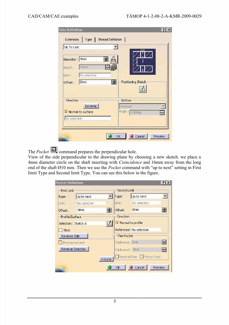
1.5 Preparation of holes
Click on one end of the body then click the Hole command. We must tune only theExtension tab, : Up To Last, Diameter 4mm.
We exact location of the hole with Positioning Sketch; here it is enough if the point of the
circle with Concentricity constrain, so we get centre bore.
7/21/2019 A06a - English
http://slidepdf.com/reader/full/a06a-english 5/8
CAD/CAM/CAE examples TÁMOP 4-1-2-08-2-A-KMR-2009-0029
5
The Pocket command prepares the perpendicular hole.View of the side perpendicular to the drawing plane by choosing a new sketch. we place a
4mm diameter circle on the shaft inserting with Coincidence and 16mm away from the long
end of the shaft Ø10 mm. Then we use the Pocket command with “up to next” setting in Firstlimit Type and Second limit Type. You can see this below in the figure.

7/21/2019 A06a - English
http://slidepdf.com/reader/full/a06a-english 6/8
CAD/CAM/CAE examples TÁMOP 4-1-2-08-2-A-KMR-2009-0029
6
1.6 Preparation of chamfers and fillets
We can make multiple edges with the Chamfer command passion which have the same preferences. We create in this method the two 1x45 angled chamfers and one 1x30 angled
chamfers.
The Edge Fillet command is similar to the Chamfer. We select the edges and give the
value. We need a 0,5 mm and a 1mm fillet.
1.7 Make the threads

7/21/2019 A06a - English
http://slidepdf.com/reader/full/a06a-english 7/8
CAD/CAM/CAE examples TÁMOP 4-1-2-08-2-A-KMR-2009-0029
7
We make the M10 type thread with Thread/Tap command. Start this command. First
section this command is the Geometrical Definition. Here we select a Lateral surface and a
Limit Surface. We need chose thread or tap type. We create thread now. Second section of
this command is the Bottom Type. Here select Dimension value because we write thread depth
with numbers. We can add the detail of thread in Numerical Definition section. We select the
Metric Thick pitch type, chose M10 for the Thread Description list. Thread Depth value is 10
mm. Write this. M10 means 10 mm diameter right handed thread. We select the Right-
Threaded text under the Pitch sign.
M10LH thread is another end of the part. It builds with same command as the first thread, but
we change the bottom type. Here we use the Support Depth type, because this thread length isequivalent the support face length. M10LH means 10 mm diameter left handed thread. We
select the Left-Threaded command on bottom of Thread/Tap Definition panel.

7/21/2019 A06a - English
http://slidepdf.com/reader/full/a06a-english 8/8
CAD/CAM/CAE examples TÁMOP 4-1-2-08-2-A-KMR-2009-0029
8
1.8 The final model