a-z owner's manual. contents mini countryman. mini paceman. · any mobile phone from within...
TRANSCRIPT

Owner's Manual.MINI Countryman.MINI Paceman.
ContentsA-Z
Online Edition for Part no. 01 40 2 911 544 - VI/13


COOPERCOOPER S
JOHN COOPERWORKS
Owner's Manual for VehicleThank you for choosing a MINI.The more familiar you are with your vehicle, the better controlyou will have on the road. We therefore strongly suggest:Read this Owner's Manual before starting off in your new MINI. Itcontains important information on vehicle operation that willhelp you make full use of the technical features available in yourMINI. The manual also contains information designed to en‐hance operating reliability and road safety, and to contribute tomaintaining the value of your MINI.Supplementary information can be found in the additional bro‐chures in the onboard literature.Set off now and have fun with your MINI.The MINI Team of BMW AG
Online Edition for Part no. 01 40 2 911 544 - VI/13

© 2013 Bayerische Motoren WerkeAktiengesellschaftMunich, GermanyReprinting, including excerpts, only with the writtenconsent of BMW AG, Munich.US English VI/13, 07 13 500Printed on environmentally friendly paper, bleachedwithout chlorine, suitable for recycling.
Online Edition for Part no. 01 40 2 911 544 - VI/13

ContentsThe fastest way to find information on a partic‐ular topic or item is by using the index, refer topage 270.
6 Notes
At a glance14 Cockpit20 Onboard monitor26 Voice activation system
Controls32 Opening and closing45 Adjusting53 Transporting children safely58 Driving68 Displays78 Lamps82 Safety93 Driving stability control systems96 Driving comfort99 Climate104 Interior equipment114 Storage compartments
Driving tips122 Things to remember when driving126 Loading130 Saving fuel
Navigation134 Navigation system136 Destination entry145 Destination guidance153 What to do if...
Entertainment156 Tone158 Radio166 CD/multimedia
Communication180 Bluetooth hands-free system190 Bluetooth mobile phone preparation
package202 Office210 MINI Connected
Mobility216 Refueling218 Fuel220 Wheels and tires232 Engine compartment234 Engine oil236 Coolant237 Maintenance239 Replacing components248 Breakdown assistance254 Care
Reference260 Technical data264 Short commands for voice activation
system270 Everything from A to Z
Online Edition for Part no. 01 40 2 911 544 - VI/13

NotesUsing this Owner'sManualThe fastest way to find information on a partic‐ular topic is by using the index.An initial overview of the vehicle is provided inthe first chapter.
Additional sources of informationShould you have any questions, your servicecenter will be glad to advise you at any time.Information on MINI, e.g., on technology, isavailable on the Internet: www.mini.com
Symbols Indicates precautions that must be followed
precisely in order to avoid the possibility of per‐sonal injury and serious damage to the vehicle.◄ Marks the end of a specific item of informa‐tion."..." Identifies Control Display texts used to se‐lect individual functions.›...‹ Verbal instructions to use with the voice ac‐tivation system.››...‹‹ Identifies the answers generated by thevoice activation system.
Refers to measures that can be taken tohelp protect the environment.
Symbols on vehicle components Indicates that you should consult the rele‐
vant section of this Owner's Manual for infor‐mation on a particular part or assembly.
Vehicle equipmentThe manufacturer of your MINI is the Bayeri‐sche Motoren Werke Aktiengesellschaft, BMWAG.This Owner's Manual describes all models, allseries equipment, as well as country-specificand special equipment offered in the modelseries. Therefore, this Owner's Manual also de‐scribes and depicts equipment that may not becontained in your vehicle because of the se‐lected special equipment or country version, forexample.This also applies to safety-related functions andsystems.For options and equipment not described inthis Owner's Manual, please refer to the Sup‐plementary Owner's Manuals.On right-hand drive vehicles, some controls arearranged differently than shown in the illustra‐tions.
Status of this Owner'sManual at time of print‐ingThe manufacturer of your vehicle pursues apolicy of constant development that is con‐ceived to ensure that our vehicles continue toembody the highest quality and safety stan‐dards. In rare cases, therefore, the features de‐scribed in this Owner's Manual may differ fromthose in your vehicle.
Seite 6
Notes
6 Online Edition for Part no. 01 40 2 911 544 - VI/13

For your own safetyWarrantyYour vehicle is technically configured for theoperating conditions and registration require‐ments applying in the country of first delivery— homologation. If your vehicle is to be oper‐ated in a different country it might be neces‐sary to adapt your vehicle to potentially differ‐ing operating conditions and permitrequirements. If your vehicle does not complywith the homologation requirements in a cer‐tain country you cannot lodge warranty claimsfor your vehicle there. Further information canbe obtained from your Service Centre.
Maintenance and repairsAdvanced technology, e.g., the use of modernmaterials and high-performance electronics,requires suitable maintenance and repairmethods.Therefore, have this work performed only by aMINI service center or a workshop that worksaccording to MINI repair procedures with ap‐propriately trained personnel.
If this work is not carried out properly, there isthe danger of subsequent damage and relatedsafety hazards.
Parts and accessoriesFor your own safety, use genuine parts and ac‐cessories approved by the manufacturer of theMINI. When you purchase accessories testedand approved by the manufacturer of the MINIand Original MINI Parts, you simultaneously ac‐quire the assurance that they have been thor‐oughly tested by the manufacturer of the MINIto ensure optimum performance when instal‐led on your vehicle. The manufacturer of theMINI warrants these parts to be free from de‐fects in material and workmanship. The manu‐facturer of the MINI will not accept any liabilityfor damage resulting from installation of partsand accessories not approved by the manufac‐
turer of the MINI. The manufacturer of the MINIcannot test every product made by other man‐ufacturers to verify if it can be used on a MINIsafely and without risk to either the vehicle, itsoperation, or its occupants. Original MINI Parts,MINI Accessories and other products approvedby the manufacturer of the MINI, together withprofessional advice on using these items, areavailable from all MINI Dealers. Installation andoperation of non-MINI approved accessoriessuch as alarms, radios, amplifiers, radar detec‐tors, wheels, suspension components, brakedust shields, telephones, including operation ofany mobile phone from within the vehicle with‐out using an externally mounted antenna, ortransceiver equipment, for instance, CBs,walkie-talkies, ham radios or similar accesso‐ries, may cause extensive damage to the vehi‐cle, compromise its safety, interfere with thevehicle's electrical system or affect the validityof the MINI Limited Warranty. See your MINIDealer for additional information. Maintenance,replacement, or repair of the emission controldevices and systems may be performed by anyautomotive repair establishment or individualusing any certified automotive part.
California Proposition 65 WarningCalifornia laws require us to state the followingwarning:Engine exhaust and a wide variety of automo‐bile components and parts, including compo‐nents found in the interior furnishings in a vehi‐cle, contain or emit chemicals known to theState of California to cause cancer and birth de‐fects and reproductive harm. In addition, cer‐tain fluids contained in vehicles and certainproducts of component wear contain or emitchemicals known to the State of California tocause cancer and birth defects or other repro‐ductive harm. Battery posts, terminals and re‐lated accessories contain lead and lead com‐pounds. Wash your hands after handling. Usedengine oil contains chemicals that have causedcancer in laboratory animals. Always protect
Seite 7
Notes
7Online Edition for Part no. 01 40 2 911 544 - VI/13
your skin by washing thoroughly with soap andwater.
Service and warrantyWe recommend that you read this publicationthoroughly. Your vehicle is covered by the fol‐lowing warranties:▷ New Vehicle Limited Warranty.▷ Rust Perforation Limited Warranty.▷ Federal Emissions System Defect Warranty.▷ Federal Emissions Performance Warranty.▷ California Emission Control System Limited
Warranty.Detailed information about these warranties islisted in the Service and Warranty InformationBooklet for US models or in the Warranty andService Guide Booklet for Canadian models.Your vehicle has been specifically adapted anddesigned to meet the particular operating con‐ditions and homologation requirements in yourcountry and continental region in order to de‐liver the full driving pleasure while the vehicle isoperated under those conditions. If you wish tooperate your vehicle in another country or re‐gion, you may be required to adapt your vehi‐cle to meet different prevailing operating con‐ditions and homologation requirements. Youshould also be aware of any applicable war‐ranty limitations or exclusions for such countryor region. In such case, please contact Cus‐tomer Relations for further information.
MaintenanceMaintain the vehicle regularly to sustain theroad safety, operational reliability and the NewVehicle Limited Warranty.Specifications for required maintenance meas‐ures:▷ MINI Maintenance system▷ Service and Warranty Information Booklet
for US models▷ Warranty and Service Guide Booklet for
Canadian models
If the vehicle is not maintained according tothese specifications, this could result in seriousdamage to the vehicle. Such damage is notcovered by the MINI New Vehicle Limited War‐ranty.
Data memoryNumerous electronic components in your vehi‐cle contain data memories that store technicalinformation on the vehicle condition, eventsand faults, either temporarily or permanently.This technical information generally documentsthe state of a component, a module, a systemor the environment.▷ Operating conditions of system compo‐
nents, such as filling levels.▷ Status messages from the vehicle and its in‐
dividual components, such as wheel rpm/speed, motion delay, transverse accelera‐tion.
▷ Malfunctions and defects in important sys‐tem components, such as lights and brakes.
▷ Vehicle responses to special driving situa‐tions, such as airbag deployment, use ofthe stability control systems.
▷ Ambient conditions, such as the tempera‐ture.
These data are of a technical nature only andare used to detect and eliminate faults and tooptimize vehicle functions. Travel profiles ofroutes driven with the vehicle cannot be cre‐ated from these data. If services are used, forinstance in the event of repairs, service proc‐esses, warranty cases, quality assurance, etc.,this technical information can be read out fromthe event and fault data memories by servicepersonnel, including the manufacturer, usingspecial diagnosis tools. This service personnelcan provide you with more information ifneeded. After troubleshooting, the informationin the fault memory is cleared or overwrittencontinuously.
Seite 8
Notes
8 Online Edition for Part no. 01 40 2 911 544 - VI/13
Situations are conceivable during the use of thevehicle in which these technical data could be‐come associated with a specific person in com‐bination with other information, such as an ac‐cident report, damage to the vehicle, witnessaccounts, etc., possibly with the involvement ofan authorized expert.Additional functions that are contractuallyagreed with the customer, such as vehicle lo‐calization in the event of an emergency, permitthe transfer of certain vehicle data out of thevehicle.
Event Data Recorder EDRThis vehicle is equipped with an event data re‐corder EDR. The main purpose of an EDR is torecord, in certain crash or near crash-like situa‐tions, such as an air bag deployment or hittinga road obstacle, data that will assist in under‐standing how a vehicle's systems performed.The EDR is designed to record data related tovehicle dynamics and safety systems for a shortperiod of time, typically 30 seconds or less.The EDR in this vehicle is designed to recordsuch data as:▷ How various systems in your vehicle were
operating.▷ Whether or not the driver and passenger
safety belts were fastened.▷ How far, if at all, the driver was depressing
the accelerator and/or brake pedal.▷ How fast the vehicle was traveling.These data can help provide a better under‐standing of the circumstances in which crashesand injuries occur.EDR data are recorded by your vehicle only if anontrivial crash situation occurs; no data are re‐corded by the EDR under normal driving condi‐tions and no personal data, e.g., name, gender,age, and crash location, are recorded.However, other parties, such as law enforce‐ment, could combine the EDR data with the
type of personally identifying data routinely ac‐quired during a crash investigation.To read data recorded by an EDR, specialequipment is required, and access to the vehi‐cle or the EDR is needed. In addition to the ve‐hicle manufacturer, other parties, such as lawenforcement, that have the special equipment,can read the information if they have access tothe vehicle or the EDR.
Reporting safety defectsFor US customersThe following only applies to vehicles ownedand operated in the US.If you believe that your vehicle has a defectwhich could cause a crash or could cause injuryor death, you should immediately inform theNational Highway Traffic Safety AdministrationNHTSA, in addition to notifying BMW of NorthAmerica, LLC, P.O. Box 1227, Westwood, NewJersey 07675-1227, Telephone1-800-831-1117.If NHTSA receives similar complaints, it mayopen an investigation, and if it finds that asafety defect exists in a group of vehicles, itmay order a recall and remedy campaign.However, NHTSA cannot become involved inindividual problems between you, your dealer,or BMW of North America, LLC.To contact NHTSA, you may call the VehicleSafety Hotline toll-free at 1-888-327-4236(TTY: 1-800-424-9153); go to http://www.safe‐rcar.gov; or write to: Administrator, NHTSA, 400Seventh Street, SW., Washington, DC 20590.You can also obtain other information aboutmotor vehicle safety from http://www.safe‐rcar.gov
For Canadian customersCanadian customers who wish to report asafety- related defect to Transport Canada, De‐fect Investigations and Recalls, may telephone
Seite 9
Notes
9Online Edition for Part no. 01 40 2 911 544 - VI/13

the toll-free hotline 1-800-333-0510. You canalso obtain other information about motor ve‐hicle safety from http://www.tc.gc.ca/roadsaf‐ety.
Seite 10
Notes
10 Online Edition for Part no. 01 40 2 911 544 - VI/13

Seite 11
Notes
11Online Edition for Part no. 01 40 2 911 544 - VI/13

WATCH ME.
Online Edition for Part no. 01 40 2 911 544 - VI/13

At a glance
Controls
Driving tips
Navigation
Entertainment
Communication
Mobility
Reference
Online Edition for Part no. 01 40 2 911 544 - VI/13

CockpitVehicle equipmentThis chapter describes all series equipment aswell as country-specific and special equipmentoffered for this model series.Therefore, it also
describes equipment that may not be found inyour vehicle, for instance due to the selectedspecial equipment or the country version. Thisalso applies to safety-related functions and sys‐tems.
All around the steering wheel
1 Setting the exterior mirror, folding it in andout 51
Power windows, front 43
MINI Countryman: power win‐dows, rear 43
MINI Countryman: safety switchfor rear power windows 44
2 Parking lamps 78
Low beams 78
Automatic headlamp con‐trol 78Adaptive Light Control 80Turn signal 61
High beams 61Headlamp flasher 61
Seite 14
At a glance Cockpit
14 Online Edition for Part no. 01 40 2 911 544 - VI/13

Roadside parking lamps 79
Computer 69
3 Tachometer 69Instrument lighting 80
Resetting the trip odometer 68
4 Washer/wiper system 61
5 Start/stop the engine and switchthe ignition on/off 58
6 Ignition lock 587 Steering wheel buttons, right
Resuming cruise control 97
Storing the speed and accelerat‐ing or slowing down 97
Activating/deactivating cruisecontrol 96
Steering wheel buttons, leftVolume
Bluetooth hands-free sys‐tem 180Bluetooth mobile phone prepara‐tion package 190Activate/deactivate the voice acti‐vation system 26
Change the radio stationSelect a music trackScroll through the redial list
8 Horn, the entire surface9 Adjust the steering wheel 5210 Releasing the hood 233
Seite 15
Cockpit At a glance
15Online Edition for Part no. 01 40 2 911 544 - VI/13

Displays
1 Tachometer 69with indicator and warning lamps 17
2 Display for▷ Current speed 68▷ Indicator/warning lamps 17
3 Resetting the trip odometer 684 Display for
▷ Automatic transmission position 65▷ Computer 69▷ Service requirements 74
▷ Odometer and trip odometer 68▷ Flat Tire Monitor 85▷ Tire Pressure Monitor 85▷ Settings and information 71▷ Personal Profile settings 32
5 Instrument lighting 806 Speedometer with indicator and warning
lamps 177 Control Display 208 Fuel gauge 69
Seite 16
At a glance Cockpit
16 Online Edition for Part no. 01 40 2 911 544 - VI/13
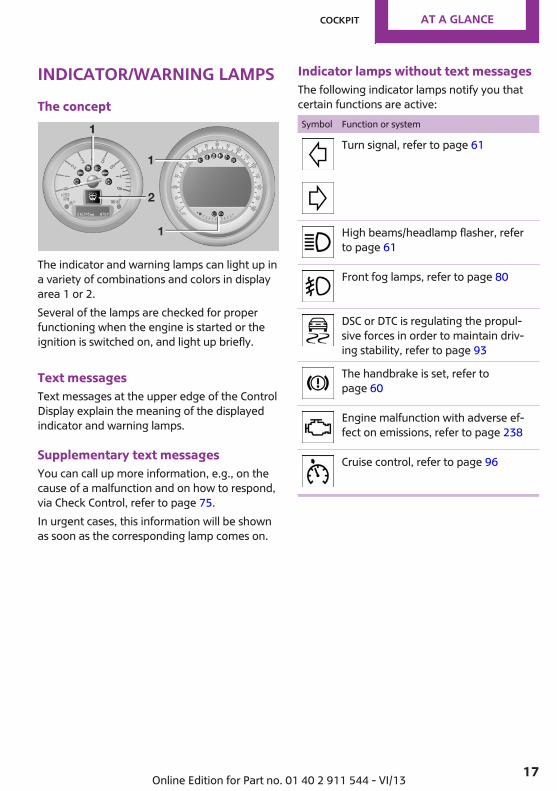
Indicator/warning lampsThe concept
The indicator and warning lamps can light up ina variety of combinations and colors in displayarea 1 or 2.Several of the lamps are checked for properfunctioning when the engine is started or theignition is switched on, and light up briefly.
Text messagesText messages at the upper edge of the ControlDisplay explain the meaning of the displayedindicator and warning lamps.
Supplementary text messagesYou can call up more information, e.g., on thecause of a malfunction and on how to respond,via Check Control, refer to page 75.In urgent cases, this information will be shownas soon as the corresponding lamp comes on.
Indicator lamps without text messagesThe following indicator lamps notify you thatcertain functions are active:Symbol Function or system
Turn signal, refer to page 61
High beams/headlamp flasher, referto page 61
Front fog lamps, refer to page 80
DSC or DTC is regulating the propul‐sive forces in order to maintain driv‐ing stability, refer to page 93
The handbrake is set, refer topage 60
Engine malfunction with adverse ef‐fect on emissions, refer to page 238
Cruise control, refer to page 96
Seite 17
Cockpit At a glance
17Online Edition for Part no. 01 40 2 911 544 - VI/13

All around the center console
1 Hazard warning system2 Speedometer with Control Display 163 Radio 158
CD/multimedia 1584 Air conditioning, automatic climate con‐
trol 995 Buttons on the center console
Seat heating 47
Central locking, inside 36
Front fog lamps 80
Sport button 95
Driving stability control systemsDSC Dynamic Stability Con‐trol 93DTC Dynamic Traction Con‐trol 94
6 Storage compartment
Seite 18
At a glance Cockpit
18 Online Edition for Part no. 01 40 2 911 544 - VI/13
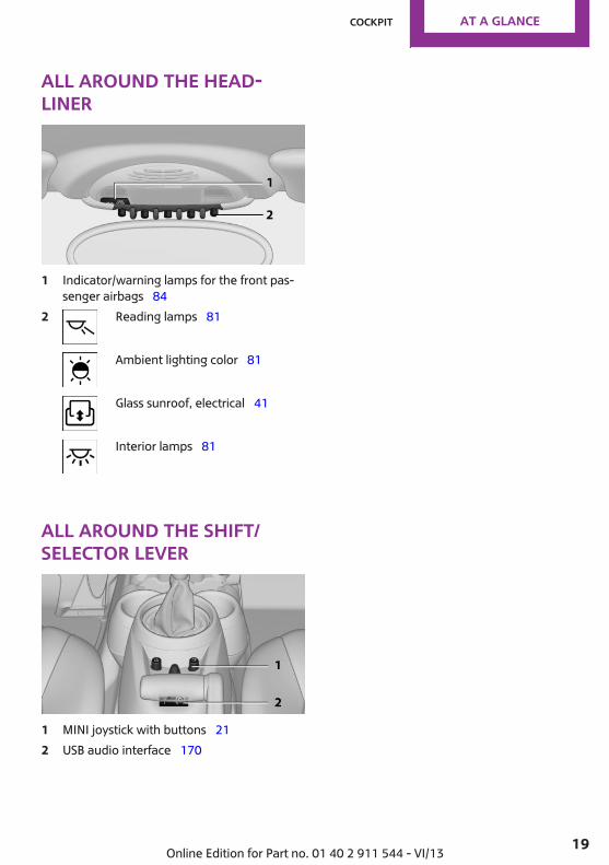
All around the head‐liner
1 Indicator/warning lamps for the front pas‐senger airbags 84
2 Reading lamps 81
Ambient lighting color 81
Glass sunroof, electrical 41
Interior lamps 81
All around the shift/selector lever
1 MINI joystick with buttons 212 USB audio interface 170
Seite 19
Cockpit At a glance
19Online Edition for Part no. 01 40 2 911 544 - VI/13

Onboard monitorVehicle equipmentThis chapter describes all series equipment aswell as country-specific and special equipmentoffered for this model series.Therefore, it alsodescribes equipment that may not be found inyour vehicle, for instance due to the selectedspecial equipment or the country version. Thisalso applies to safety-related functions and sys‐tems.
The conceptThe onboard monitor combines the functionsof a large number of different switches. Thus,these functions can be operated from a centrallocation.
Using the onboard monitor during a tripTo avoid becoming distracted and posing
an unnecessary hazard to your vehicle's occu‐pants and to other road users, never attempt touse the controls or enter information unlesstraffic and road conditions allow this.◀
Controls at a glanceControls
1 Control Display2 MINI joystick with buttons
The buttons can be used to open the me‐nus directly. The MINI joystick can be usedto select menu items and create settings.
Control Display
Notes▷ To clean the Control Display, follow the care
instructions, refer to page 257.▷ Do not place objects close to the Control
Display; otherwise, the Control Display canbe damaged.
Switching off1. Move the MINI joystick repeatedly to the
right until the "Options" menu appears.2. "Switch off control display"
Switching onPress the MINI joystick to switch on.
Seite 20
At a glance Onboard monitor
20 Online Edition for Part no. 01 40 2 911 544 - VI/13

MINI joystick with buttonsSelect menu items and create settings.
1. Turn, arrow 1.
2. Press, arrow 2.3. Move in four directions.
Buttons on the MINI joystick
Press the button Function
Opens the main menu.
Changes to another menu.
Operating conceptStart screenIn the radio ready state and higher, the follow‐ing message appears on the Control Display:
To hide the message: press the MINI joystick.The main menu is displayed.The message is automatically hidden after ap‐prox. 10 seconds.
Opening the main menu
Press the button.
The main menu is displayed.
All onboard monitor functions can be called upvia the main menu.
Seite 21
Onboard monitor At a glance
21Online Edition for Part no. 01 40 2 911 544 - VI/13

Selecting menu itemsMenu items shown in white can be selected.
1. Turn the MINI joystick until the desiredmenu item is highlighted.
2. Press the MINI joystick.A new menu is displayed or the function is per‐formed.With the button on the MINI joystick:
Press the button.The menu items of the main menu can beopened consecutively by pressing the buttonrepeatedly.
Menu items in the Owner's ManualIn the Owner's Manual, menu items that can beselected are set in quotation marks, e.g.,"Settings".
Changing between panelsAfter a menu item is selected, e.g., "Radio", anew panel is displayed. Panels can overlap.▷ Move the MINI joystick to the left.
The current panel is closed and the previ‐ous panel is displayed.
▷ Move the MINI joystick to the right.A new panel is opened on top of the previ‐ous display.
Arrows pointing to the left or right indicate thatadditional panels can be opened.
View of an opened menuWhen a menu is opened, it generally openswith the panel that was last selected in thatmenu. To display the first panel of a menu:Move the MINI joystick to the left repeatedlyuntil the first panel is displayed.
Opening the Options menuMove the MINI joystick repeatedly to the rightuntil the "Options" menu appears.
Options menuThe "Options" menu consists of various areas:▷ Screen settings, e.g., "Switch off control
display".▷ Control options for the selected main
menu, e.g., for "Radio".▷ If applicable, further operating options for
the selected menu, for instance "Storestation".
Seite 22
At a glance Onboard monitor
22 Online Edition for Part no. 01 40 2 911 544 - VI/13

Changing settings1. Select a field.2. Turn the MINI joystick until the desired set‐
ting is displayed.
3. Press the MINI joystick to confirm the set‐ting.
Activating/deactivating the functionsSeveral menu items are preceded by a check‐box. It indicates whether the function is acti‐vated or deactivated. Selecting the menu itemactivates or deactivates the function.
The function is activated. The function is deactivated.
Example: setting theclockSetting the clock
1. Press the button. The main menu isdisplayed.
2. Turn the MINI joystick until "Settings" ishighlighted and press the MINI joystick.
3. If necessary, move the MINI joystick to theleft to display "Time/Date".
4. Turn the MINI joystick until "Time/Date" ishighlighted and press the MINI joystick.
5. Turn the MINI joystick to set the hours andpress the MINI joystick.
6. Turn the MINI joystick to set the minutesand press the MINI joystick.
Status informationStatus fieldThe following information is displayed in thestatus field at the top right:
Seite 23
Onboard monitor At a glance
23Online Edition for Part no. 01 40 2 911 544 - VI/13

▷ Time.▷ Current entertainment source.▷ Sound output, on/off.▷ Wireless network reception strength.▷ Telephone status.▷ Traffic bulletin reception.Check Control messages and entries using thevoice activation system temporarily hide thestatus information.
Status field symbolsThe symbols are grouped into various catego‐ries.
Radio symbols
Symbol Meaning
HD Radio™ is switched on.
Satellite radio is switched on.
Telephone symbols
Symbol Meaning
Incoming or outgoing call.
Wireless network reception strengthSymbol flashes: searching for network.
Wireless network is not available.
Bluetooth is switched on.
Roaming is active.
Text message, e-mail was received.
Entertainment symbols
Symbol Meaning
CD player.
AUX-IN port.
Symbol Meaning
USB audio interface.
Music interface for smartphones.
Additional symbols
Symbol Meaning
Spoken instructions are switched off.
Entering letters andnumbersGeneral information1. Turn the MINI joystick: select letters or
numbers.2. Select additional letters or numbers if
needed.3. "OK": confirm the entry.
Symbol Function
Press the MINI joystick: delete the let‐ter or number.
Press the MINI joystick for an ex‐tended period: delete all letters ornumbers.
Enter a blank space.
Switching between letters and numbersDepending on the menu, you can switch be‐tween entering letters and numbers.
Seite 24
At a glance Onboard monitor
24 Online Edition for Part no. 01 40 2 911 544 - VI/13

Symbol Function
Enter the letters.
Enter the numbers.
Switching between upper and lowercase lettersDepending on the menu, you can switch be‐tween entering uppercase and lowercase let‐ters.Symbol Function
Move the MINI joystick forward:switch from upper to lower caseletters.
Move the MINI joystick forward:switch from lower to upper caseletters.
Entry comparisonEntry of names and addresses: the selection isnarrowed down every time a letter is enteredand letters may be added automatically.The entries are continuously compared to thedata stored in the vehicle.▷ Only those letters are offered during the
entry for which data is available.▷ Destination search: town/city names can be
entered using the spelling of languageavailable on the Control Display.
Seite 25
Onboard monitor At a glance
25Online Edition for Part no. 01 40 2 911 544 - VI/13

Voice activation systemVehicle equipmentThis chapter describes all series equipment aswell as country-specific and special equipmentoffered for this model series.Therefore, it alsodescribes equipment that may not be found inyour vehicle, for instance due to the selectedspecial equipment or the country version. Thisalso applies to safety-related functions and sys‐tems.
The concept▷ Most functions that are displayed on the
Control Display can be operated with thevoice activation system using spoken com‐mands. The system prompts you to makeyour entries.
▷ Functions that can only be used when thevehicle is stationary cannot be operated us‐ing the voice activation system.
▷ The system uses a special microphone inthe headliner on the driver's side.
▷ ›...‹ Verbal instructions in the Owner'sManual to use with the voice activation sys‐tem.
RequirementsVia the Control Display, set a language that isalso supported by the voice activation systemso that the spoken commands can be identi‐fied.Set the language, refer to page 73.
Using voice activationActivating the voice activation system
1. Press the button on the steeringwheel.
2. Wait for the signal. This symbol on the Control Display indi‐
cates that the voice activation system is ac‐tive.
3. Say the command.The command appears on the Control Dis‐play.
If no other commands are available, operatethe function via the onboard monitor in thiscase.
Terminating the voice activationsystem
Briefly press the button on the steeringwheel or ›Cancel‹.
Possible commandsMost menu items on the Control Display can bevoiced as commands.The available commands depend on the menuthat is currently displayed on the Control Dis‐play.
Seite 26
At a glance Voice activation system
26 Online Edition for Part no. 01 40 2 911 544 - VI/13
The functions of the main menu have shortcommands.Some list items, such as the phone book en‐tries, can also be selected via the voice activa‐tion system. Say the list items exactly as theyare displayed on the list.
Having possible commands read aloudYou can have the system read possible com‐mands aloud: ›Voice commands‹.For example, if the "CD" menu is displayed, thecommands for the operating the CD player areread out loud.
Executing functions using shortcommandsFunctions on the main menu can be performeddirectly by means of short commands, usuallyirrespective of which menu item is currently se‐lected, for instance ›Vehicle status‹.List of short commands of the voice activationsystem, refer to page 264.
Help dialog for the voice activationsystemCalling up help dialog: ›Help‹Additional commands for the help dialog:▷ ›Help with examples‹: information about
the current operating options and the mostimportant commands for them are an‐nounced.
▷ ›Help with voice activation‹: informationabout the principle of operation for thevoice activation system is announced.
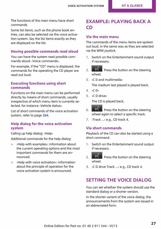
Example: playing back aCDVia the main menuThe commands of the menu items are spokenout loud, in the same way as they are selectedvia the MINI joystick.
1. Switch on the Entertainment sound outputif necessary.
2. Press the button on the steeringwheel.
3. ›C D and multimedia‹The medium last played is played back.
4. ›C D‹5. ›C D drive‹
The CD is played back.
6. Press the button on the steeringwheel again to select a specific track.
7. ›Track ...‹ e.g., CD track 4.
Via short commandsPlayback of the CD can also be started using ashort command.
1. Switch on the Entertainment sound outputif necessary.
2. Press the button on the steeringwheel.
3. ›C D drive Track ...‹ e.g., CD track 4.
Setting the voice dialogYou can set whether the system should use thestandard dialog or a shorter version.In the shorter variant of the voice dialog, theannouncements from the system are issued inan abbreviated form.
Seite 27
Voice activation system At a glance
27Online Edition for Part no. 01 40 2 911 544 - VI/13

On the Control Display:
1. "Settings"2. "Language/Units"3. "Speech mode:"4. Select the setting.
Adjusting the volumeTurn the volume knob while giving an instruc‐tion until the desired volume is set.▷ The volume remains constant even if the
volume of other audio sources is changed.▷ The volume is stored for the remote control
currently in use.
Notes on Emergency Re‐questsDo not use the voice activation system to ini‐tiate an Emergency Request. In stressful situa‐tions, the voice and vocal pitch can change.This can unnecessarily delay the establishmentof a telephone connection.
Environmental condi‐tions▷ Say the commands, numbers, and letters
smoothly and with normal volume, empha‐sis, and speed.
▷ Always say commands in the language ofthe voice activation system.
▷ Avoid making other noise in the vehiclewhile speaking.
Seite 28
At a glance Voice activation system
28 Online Edition for Part no. 01 40 2 911 544 - VI/13

Seite 29
Voice activation system At a glance
29Online Edition for Part no. 01 40 2 911 544 - VI/13

HANDLE ME.
Online Edition for Part no. 01 40 2 911 544 - VI/13

At a glance
Controls
Driving tips
Navigation
Entertainment
Communication
Mobility
Reference
Online Edition for Part no. 01 40 2 911 544 - VI/13
Opening and closingVehicle equipmentThis chapter describes all series equipment aswell as country-specific and special equipmentoffered for this model series.Therefore, it alsodescribes equipment that may not be found inyour vehicle, for instance due to the selectedspecial equipment or the country version. Thisalso applies to safety-related functions and sys‐tems.
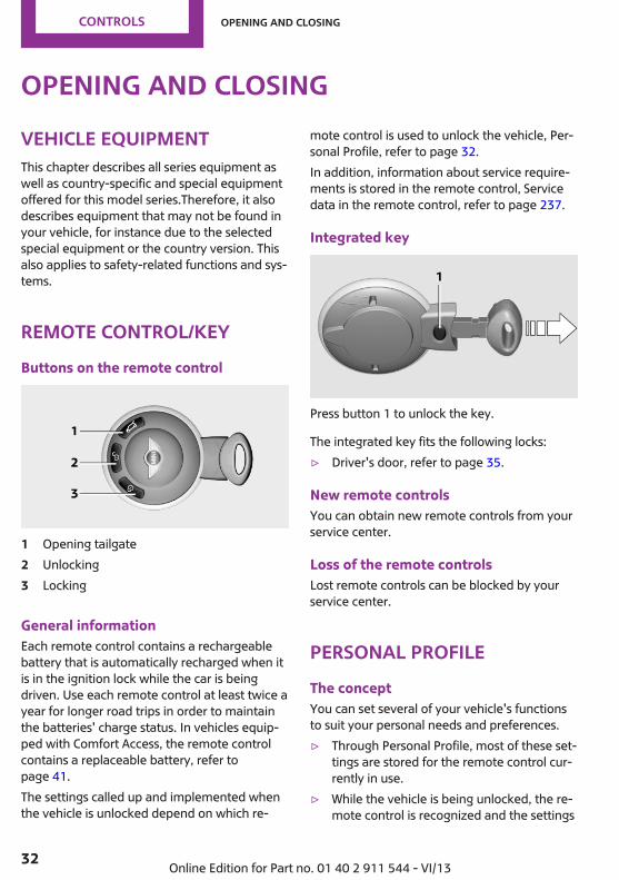
Remote control/keyButtons on the remote control
1 Opening tailgate2 Unlocking3 Locking
General informationEach remote control contains a rechargeablebattery that is automatically recharged when itis in the ignition lock while the car is beingdriven. Use each remote control at least twice ayear for longer road trips in order to maintainthe batteries' charge status. In vehicles equip‐ped with Comfort Access, the remote controlcontains a replaceable battery, refer topage 41.The settings called up and implemented whenthe vehicle is unlocked depend on which re‐
mote control is used to unlock the vehicle, Per‐sonal Profile, refer to page 32.In addition, information about service require‐ments is stored in the remote control, Servicedata in the remote control, refer to page 237.
Integrated key
Press button 1 to unlock the key.
The integrated key fits the following locks:▷ Driver's door, refer to page 35.
New remote controlsYou can obtain new remote controls from yourservice center.
Loss of the remote controlsLost remote controls can be blocked by yourservice center.
Personal ProfileThe conceptYou can set several of your vehicle's functionsto suit your personal needs and preferences.▷ Through Personal Profile, most of these set‐
tings are stored for the remote control cur‐rently in use.
▷ While the vehicle is being unlocked, the re‐mote control is recognized and the settings
Seite 32
Controls Opening and closing
32 Online Edition for Part no. 01 40 2 911 544 - VI/13

stored with it are called up and imple‐mented.
▷ Your personal settings will be recognizedand called up again even if the vehicle hasbeen used in the meantime by someoneelse with another remote control.
▷ The individual settings are stored for nomore than three remote controls.
Personal Profile settingsThe following functions and settings can bestored in a profile.More information on the settings can be foundunder:▷ Response of the central locking system
when the car is being unlocked, refer topage 34.
▷ Automatic locking of the vehicle, refer topage 37.
▷ Triple turn signal activation, refer topage 61.
▷ Settings for the displays on the onboardmonitor, in the speedometer, and in thetachometer:▷ 12h/24h clock format, refer to
page 72.▷ Date format, refer to page 73.▷ Brightness of the Control Display, refer
to page 74.▷ Language on the Control Display, refer
to page 73.▷ Units of measure for fuel consumption,
distance covered/remaining distances,and temperature, refer to page 72.
▷ Light settings:▷ Headlamp courtesy delay feature, refer
to page 79.▷ Daytime running lights, refer to
page 79.▷ Automatic climate control, refer to
page 101: AUTO program, activating/deac‐tivating the cooling function, setting the
temperature, air volume, and air distribu‐tion.
▷ Entertainment:▷ Tone settings, refer to page 156.▷ Volume, refer to page 156.
Central locking systemThe conceptThe central locking system becomes activewhen the driver's door is closed.The system simultaneously engages and re‐leases the locks on the following:▷ Doors.▷ Tailgate.▷ Fuel filler flap.
Operating from the outside▷ Via the remote control.▷ Via the door lock.▷ In cars with Comfort Access, via the door
handles on the driver's and front passengersides.
The following takes place simultaneously whenlocking/unlocking the vehicle via the remotecontrol:▷ Depending on the vehicle equipment, the
anti-theft protection is switched on and offas well. The anti-theft protection makes itimpossible to unlock the doors using thelock buttons or door handles.
▷ The welcome lamps, interior lamps, andambient lighting are switched on and off.
▷ The alarm system is armed or disarmed, re‐fer to page 41.
Operating from the insideVia the switch/button for the central lockingsystem, refer to page 36.
Seite 33
Opening and closing Controls
33Online Edition for Part no. 01 40 2 911 544 - VI/13
In an accident of the necessary severity, thecentral locking system unlocks automatically.The hazard warning system and interior lampscome on.
Opening and closing:from the outsideUsing the remote control
General informationTake the remote control with youPeople or animals left unattended in a
parked vehicle can lock the doors from the in‐side. Always take the remote control with youwhen leaving the vehicle so that the vehiclecan then be opened from the outside.◀
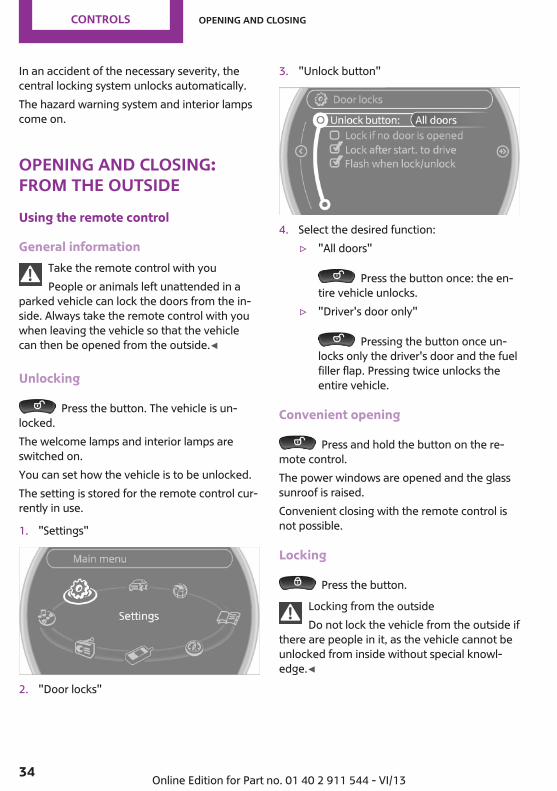
Unlocking
Press the button. The vehicle is un‐locked.The welcome lamps and interior lamps areswitched on.You can set how the vehicle is to be unlocked.The setting is stored for the remote control cur‐rently in use.
1. "Settings"
2. "Door locks"
3. "Unlock button"
4. Select the desired function:▷ "All doors"
Press the button once: the en‐tire vehicle unlocks.
▷ "Driver's door only"
Pressing the button once un‐locks only the driver's door and the fuelfiller flap. Pressing twice unlocks theentire vehicle.
Convenient opening
Press and hold the button on the re‐mote control.The power windows are opened and the glasssunroof is raised.Convenient closing with the remote control isnot possible.
Locking
Press the button.Locking from the outsideDo not lock the vehicle from the outside if
there are people in it, as the vehicle cannot beunlocked from inside without special knowl‐edge.◀
Seite 34
Controls Opening and closing
34 Online Edition for Part no. 01 40 2 911 544 - VI/13

Setting the confirmation signalsHave unlocking or locking of the vehicle con‐firmed.
1. "Settings"2. "Door locks"3. "Flash when lock/unlock"
4. Press the MINI joystick.
Switching on the interior lampsWhen the vehicle is locked:
Press the button.You can also use this function to locate your ve‐hicle in parking garages, etc.
Unlocking the tailgate
Press the button for approx. 1 secondand then release it.The tailgate pivots back and up when it opens.Ensure that adequate clearance is available be‐fore opening.
MalfunctionsThe function of the remote control may be im‐paired by local radio waves. If this occurs, un‐lock and lock the vehicle at the door lock withthe integrated key.If it should become impossible to lock the vehi‐cle with a remote control, the battery in the re‐mote control is discharged. Use this remotecontrol on an extended trip to recharge thebattery, refer to page 32.
For US owners onlyThe transmitter and receiver units comply withpart 15 of the FCC/Federal CommunicationCommission regulations. Operation is governedby the following:FCC ID:LX8766SLX8766ELX8CASCompliance statement:This device complies with part 15 of the FCCRules. Operation is subject to the following twoconditions:▷ This device may not cause harmful interfer‐
ence, and▷ this device must accept any interference re‐
ceived, including interference that maycause undesired operation.
Any unauthorized modifications or changes tothese devices could void the user's authority tooperate this equipment.
Using the door lock
Sets how the vehicle is to be unlocked, refer topage 34.
In some vehicle equipment versions, only thedriver's door can be unlocked and locked viathe door lock.
Seite 35
Opening and closing Controls
35Online Edition for Part no. 01 40 2 911 544 - VI/13

Locking from the outsideDo not lock the vehicle from the outside if
there are people in it, as the vehicle cannot beunlocked from inside without special knowl‐edge.◀
Locking the doors and tailgate at onceTo lock all doors, the fuel filler flap, and the tail‐gate at once:
1. With the doors closed, lock the vehicle us‐ing the button for the central locking sys‐tem in the interior, refer to page 36.
2. Unlock and open the driver's or front pas‐senger door, refer to page 37.
3. To lock the vehicle:▷ Lock the driver's door using the
integrated key in the door lock, or▷ Press down the lock button of the front
passenger door and close the doorfrom the outside.
Convenient opening and closingIn vehicles with an alarm system or Comfort Ac‐cess, the windows and the glass sunroof can beoperated via the door lock.
Opening/closingTurn the key to the unlock or lock position andhold it there.
Keep the closing area clearWatch during the opening and closing
process to be sure that no one becomes trap‐ped. Releasing the key stops the motion.◀
Manual operationIf an electrical malfunction occurs, the driver'sdoor can be unlocked or locked by turning theintegrated key to the end positions of the doorlock.
Opening and closing:from the insideOperation via▷ Switch in the center console:
▷ Button in the driver's or front passengerdoor:
The graphic shows the button in the MINI Pace‐man as an example.The switch or the buttons can be used to lockor unlock the doors and tailgate when thedoors are closed, but they are not theft-pro‐tected. The fuel filler flap remains unlocked.
Seite 36
Controls Opening and closing
36 Online Edition for Part no. 01 40 2 911 544 - VI/13
Unlocking and opening doors▷ Using the switch or the buttons for the cen‐
tral locking system, unlock all of the doorsat once and then pull the door openerabove the armrest, or
▷ Pull the door handle on each door twice:the door is unlocked the first time andopened the second time.
Locking▷ Press the switch/button or▷ Push down the lock button of a door. To
avoid locking yourself out by accident, thedriver's door cannot be locked at the lockbutton while the door is open.
Automatic lockingIn addition, it is possible to set the situations inwhich the vehicle locks. The setting is stored forthe remote control in use.
1. "Settings"2. "Door locks"3. Select a menu item:
▷ "Lock if no door is opened"The central locking system locks after ashort period if no door is opened.
▷ "Lock after start. to drive"The central locking system locks whenyou start driving.
Take the remote control with youPeople or animals left unattended in a
parked vehicle can lock the doors from the in‐side. Always take the remote control with youwhen leaving the vehicle so that the vehiclecan then be opened from the outside.◀
TailgateOpeningThe tailgate pivots back and up when it opens.Ensure that adequate clearance is available be‐fore opening.
Provide edge protectionSharp or angular objects can hit the rear
window while driving and damage the heatingwires of the rear window. Provide edge protec‐tion.◀
Only drive with the tailgate fully closed; other‐wise, the tail lamps will be hidden from viewand driving safety will be compromised.In some market-specific versions, the tailgatecan only be unlocked using the remote controlif the vehicle was unlocked first.
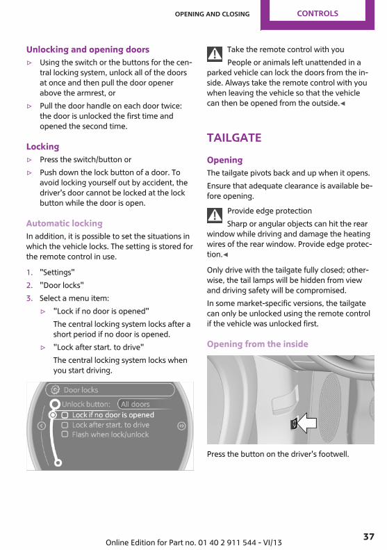
Opening from the inside
Press the button on the driver's footwell.
Seite 37
Opening and closing Controls
37Online Edition for Part no. 01 40 2 911 544 - VI/13

MINI Countryman
Press the top half of the MINI emblem, arrow,or
Press the button on the remote controlfor approx. 1 second and release. The tailgate isunlocked.
MINI Paceman
Press the top half of the MINI emblem, arrow,or
Press the button on the remote controlfor approx. 1 second and release. The tailgate isunlocked.
ClosingKeep the closing area clearMake sure that the closing area of the
tailgate is clear; otherwise, injuries or damagemay result.◀
Take the remote control with youAlways take the remote control with you
when leaving the vehicle and do not place it inthe cargo area; otherwise, the remote controlmay be locked into the vehicle when the tail‐gate is closed.◀
MINI Countryman
Recessed grips on the inside trim of the tailgatecan be used to conveniently pull down the tail‐gate.
MINI Paceman
Recessed grips on the inside trim of the tailgatecan be used to conveniently pull down the tail‐gate.
Comfort AccessThe conceptThe vehicle can be accessed without activatingthe remote control. All you need to do is tohave the remote control with you, e.g., in your
Seite 38
Controls Opening and closing
38 Online Edition for Part no. 01 40 2 911 544 - VI/13

jacket pocket. The vehicle automatically de‐tects the remote control when it is nearby or inthe passenger compartment.Comfort Access supports the following func‐tions:▷ Unlocking/locking of the vehicle.▷ Unlocking of the tailgate separately.▷ Starting the engine.
Functional requirements▷ There are no external sources of interfer‐
ence in the vicinity.▷ To lock the vehicle, the remote control
must be located outside of the vehicle.▷ The next unlocking and locking cycle is not
possible until after approx. 2 seconds.▷ The engine can only be started if the re‐
mote control is inside the vehicle.▷ The doors and tailgate must be closed to
operate the windows.
Comparison with ordinary remotecontrolThe functions can be controlled by pressing thebuttons or via Comfort Access.Notes on opening and closing, refer to page 32.If you notice a brief delay while opening orclosing the windows or glass sunroof, the sys‐tem is checking whether a remote control is in‐side the vehicle. Repeat the opening or closingprocedure, if necessary.
Unlocking
Press button 1.
Depending on the setting, either only the driv‐er's door or the entire vehicle is unlocked, referto page 34.Pressing the button again locks the entire vehi‐cle again.Convenient opening with the remote control,refer to page 34.
LockingPress button 1.For Convenient closing, press and hold but‐ton 1.The windows and glass sunroof are closed inaddition.
Unlocking the tailgate separatelyPress the top half of the MINI emblem.This corresponds to pressing the following but‐
ton on the remote control: .If a remote control accidentally left in the cargoarea is detected in the locked vehicle after thetailgate is closed, the tailgate opens againslightly. The hazard warning system flashes andan acoustic signal sounds.
Power windows and electrical glasssunroofWhen the engine is switched off, the windowsand the sunroof can be operated as long asneither the doors nor the tailgate are opened.
Seite 39
Opening and closing Controls
39Online Edition for Part no. 01 40 2 911 544 - VI/13

When the door and tailgate are closed againand the remote control is detected inside thevehicle, the windows and the sunroof can beoperated again.Insert the remote control into the ignition lockto be able to operate the windows and the sun‐roof while the engine is switched off and thedoors are open.
Switching on the radio ready statePress the Start/Stop button to switch on theradio ready state, refer to page 58.Do not depress the brake or the clutch; other‐wise, the engine will start.
Starting the engineThe engine can be started or the ignition canbe switched on, refer to page 58, when a re‐mote control is inside the vehicle. It is not nec‐essary to insert a remote control into the igni‐tion lock.
Switching off the engine in cars withautomatic transmissionThe engine can only be switched off with theselector lever in position P, refer to page 65.To switch off the engine with the selector leverin position N, the remote control must be in‐serted in the ignition lock.
Before driving a vehicle with automatictransmission into a car wash1. Insert the remote control into the ignition
switch.2. Depress the brake pedal.3. Move the selector lever to position N.4. Switch the engine off.The vehicle can roll.
MalfunctionThe Comfort Access functions can be disturbedby local radio waves, such as by a mobilephone in the immediate vicinity of the remote
control or when a mobile phone is beingcharged in the vehicle.If this occurs, open or close the vehicle usingthe buttons on the remote control or use theintegrated key in the door lock.To start the engine afterward, insert the remotecontrol into the ignition switch.
Warning lampsThe warning lamp in the instrumentcluster lights up when you attempt tostart the engine: the engine cannot be
started.The remote control is not in the vehicle or has amalfunction. Take the remote control with youinside the vehicle or have it checked. If neces‐sary, insert another remote control into the ig‐nition switch.
The warning lamp in the instrumentcluster lights up while the engine is run‐ning: the remote control is no longer in‐
side the vehicle.After switching off the engine, the engine canonly be started again within approx. 10 sec‐onds if no door has been opened.
The indicator lamp lights up and a mes‐sage appears on the Control Display: re‐place the remote control battery.
Seite 40
Controls Opening and closing
40 Online Edition for Part no. 01 40 2 911 544 - VI/13
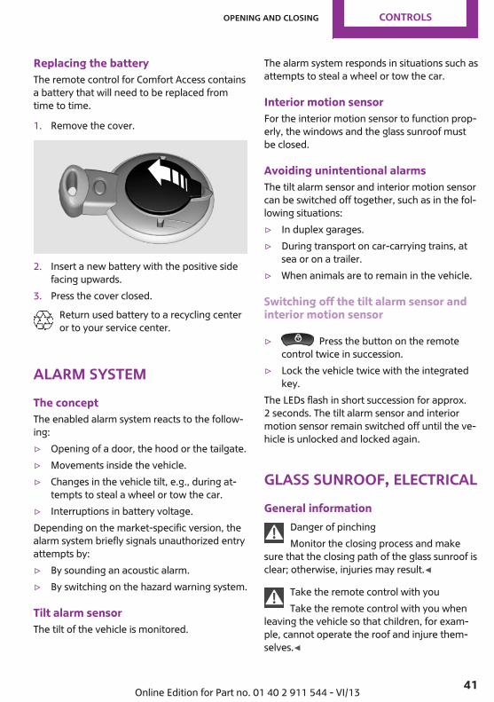
Replacing the batteryThe remote control for Comfort Access containsa battery that will need to be replaced fromtime to time.
1. Remove the cover.
2. Insert a new battery with the positive sidefacing upwards.
3. Press the cover closed.Return used battery to a recycling centeror to your service center.
Alarm systemThe conceptThe enabled alarm system reacts to the follow‐ing:▷ Opening of a door, the hood or the tailgate.▷ Movements inside the vehicle.▷ Changes in the vehicle tilt, e.g., during at‐
tempts to steal a wheel or tow the car.▷ Interruptions in battery voltage.Depending on the market-specific version, thealarm system briefly signals unauthorized entryattempts by:▷ By sounding an acoustic alarm.▷ By switching on the hazard warning system.
Tilt alarm sensorThe tilt of the vehicle is monitored.
The alarm system responds in situations such asattempts to steal a wheel or tow the car.
Interior motion sensorFor the interior motion sensor to function prop‐erly, the windows and the glass sunroof mustbe closed.
Avoiding unintentional alarmsThe tilt alarm sensor and interior motion sensorcan be switched off together, such as in the fol‐lowing situations:▷ In duplex garages.▷ During transport on car-carrying trains, at
sea or on a trailer.▷ When animals are to remain in the vehicle.
Switching off the tilt alarm sensor andinterior motion sensor
▷ Press the button on the remotecontrol twice in succession.
▷ Lock the vehicle twice with the integratedkey.
The LEDs flash in short succession for approx.2 seconds. The tilt alarm sensor and interiormotion sensor remain switched off until the ve‐hicle is unlocked and locked again.
Glass sunroof, electricalGeneral information
Danger of pinchingMonitor the closing process and make
sure that the closing path of the glass sunroof isclear; otherwise, injuries may result.◀
Take the remote control with youTake the remote control with you when
leaving the vehicle so that children, for exam‐ple, cannot operate the roof and injure them‐selves.◀
Seite 41
Opening and closing Controls
41Online Edition for Part no. 01 40 2 911 544 - VI/13

Convenient operation via:▷ Door lock, refer to page 35▷ Comfort Access, refer to page 39
Tilting the glass sunroofMINI Countryman:▷ Press the switch back to the resistance
point and hold.Both glass sunroofs are raised.Releasing stops the motion.
▷ With the ignition switched on, press theswitch back past the resistance point.Both closed glass sunroofs are raised fully.Pressing again stops the motion.
MINI Paceman:▷ Press the switch back to the resistance
point and hold.The front glass sunroof is raised.Releasing stops the motion.
▷ With the ignition switched on, press theswitch back past the resistance point.The front glass sunroof is fully raised.Pressing again stops the motion.
Opening, closingMINI Countryman:▷ In the raised position with the ignition
switched on, press the switch back andhold.The front glass sunroof is opened. The rearglass sunroof is closed.
Releasing stops the motion.The same method is used to close the glasssunroof, in this case by pressing the switch for‐ward.The front glass sunroof remains in the raisedposition. The rear glass sunroof is raised. Press‐ing again closes both sunroofs completely.MINI Paceman:▷ In the raised position with the ignition
switched on, press the switch back andhold.The front glass sunroof is opened.Releasing stops the motion.
The same method is used to close the glasssunroof, in this case by pressing the switch for‐ward.The front glass sunroof remains in the raisedposition. Pressing again closes the roof com‐pletely.
Roller sunblindThe roller sunblind can be opened and closedseparately from the glass sunroof.
After a power failureAfter a power failure, it could happen that thesunroof can only be raised. In this case, havethe system initialized. The manufacturer of yourMINI recommends having this work performedby the service center.
Power windowsGeneral information
Danger of pinchingMonitor the closing process and make
sure that the closing path of the window isclear; otherwise, injuries may result.◀
Seite 42
Controls Opening and closing
42 Online Edition for Part no. 01 40 2 911 544 - VI/13
Take the remote control with youTake the remote control with you when
leaving the vehicle so that children, for exam‐ple, cannot operate the power windows and in‐jure themselves.◀
If, after having been opened and closed a num‐ber of times in close succession, a window canonly be closed, the system is overheated. Letthe system cool down for several minutes withthe ignition switched on or the engine running.
Opening, closing
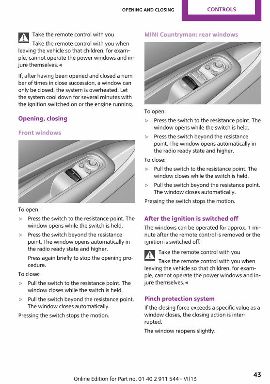
Front windows
To open:▷ Press the switch to the resistance point. The
window opens while the switch is held.▷ Press the switch beyond the resistance
point. The window opens automatically inthe radio ready state and higher.Press again briefly to stop the opening pro‐cedure.
To close:▷ Pull the switch to the resistance point. The
window closes while the switch is held.▷ Pull the switch beyond the resistance point.
The window closes automatically.Pressing the switch stops the motion.
MINI Countryman: rear windows
To open:▷ Press the switch to the resistance point. The
window opens while the switch is held.▷ Press the switch beyond the resistance
point. The window opens automatically inthe radio ready state and higher.
To close:▷ Pull the switch to the resistance point. The
window closes while the switch is held.▷ Pull the switch beyond the resistance point.
The window closes automatically.Pressing the switch stops the motion.
After the ignition is switched offThe windows can be operated for approx. 1 mi‐nute after the remote control is removed or theignition is switched off.
Take the remote control with youTake the remote control with you when
leaving the vehicle so that children, for exam‐ple, cannot operate the power windows and in‐jure themselves.◀
Pinch protection systemIf the closing force exceeds a specific value as awindow closes, the closing action is inter‐rupted.The window reopens slightly.
Seite 43
Opening and closing Controls
43Online Edition for Part no. 01 40 2 911 544 - VI/13

Danger of pinching even with pinch pro‐tection
Even with the pinch protection system, checkthat the window's closing path is clear; other‐wise, the closing action may not stop in certainsituations, e.g., if thin objects are present.◀
Do not use window accessoriesDo not install any accessories in the range
of movement of the windows; otherwise, thepinch protection system will be impaired.◀
Closing without the pinch protectionsystem
Danger of pinchingMonitor the closing process and make
sure that the closing path of the window isclear; otherwise, injuries may result.◀
If there is an external danger or, for example, ifice on the windows prevents a window fromclosing normally, the window can be closedmanually.
1. Pull the switch past the resistance point andhold it there. Pinch protection is limited andthe window reopens slightly if the closingforce exceeds a certain value.
2. Pull the switch past the resistance pointagain within approx. 4 seconds and hold itthere.The window closes without pinch protec‐tion.
MINI Countryman: safety switch
With the safety switch, the rear windows areprevented from being opened or closed via theswitches in the rear passenger area, such as bychildren.Press the button. The LED lights up if the safetyfunction is switched on.
Safety switch for rear operationPress the safety switch when transporting
children in the rear; otherwise, injury may resultif the windows are closed without supervi‐sion.◀
Seite 44
Controls Opening and closing
44 Online Edition for Part no. 01 40 2 911 544 - VI/13

AdjustingVehicle equipmentThis chapter describes all series equipment aswell as country-specific and special equipmentoffered for this model series.Therefore, it alsodescribes equipment that may not be found inyour vehicle, for instance due to the selectedspecial equipment or the country version. Thisalso applies to safety-related functions and sys‐tems.
Sitting safelyThe ideal seating position can make a vital con‐tribution to relaxed, fatigue-free driving.The seating position plays an important role inan accident in combination with:▷ Safety belts, refer to page 47▷ Head restraints, refer to page 50.▷ Airbags, refer to page 82.
SeatsNote before adjusting
Do not adjust the seat while drivingNever attempt to adjust the driver's seat
while driving. The seat could respond with un‐expected movement and the ensuing loss ofvehicle control could lead to an accident.◀
Do not incline the backrest too far to therear
Do not incline the backrest on the front passen‐ger side too far to the rear during driving. Oth‐erwise, there is the danger of sliding under thesafety belt in an accident. This would eliminatethe protection normally provided by the belt.◀
Front seat adjustment
Forward/backward
Pull the lever, arrow 1, and slide the seat intothe desired position, arrows 2.After releasing the lever, move the seat forwardor back slightly to make sure it engages prop‐erly.
Height
Pull the lever up or push it down repeatedly, ar‐rows 1, until the desired height is reached, ar‐rows .
BackrestMINI Countryman
Seite 45
Adjusting Controls
45Online Edition for Part no. 01 40 2 911 544 - VI/13

Pull the lever, arrow 1, and apply your weightto the backrest or lift it off, as necessary.
MINI Paceman
Pull the lever, arrow 1, and apply your weightto the backrest or lift it off, as necessary, ar‐rows 2.
Lumbar supportYou can also adjust the contour of the backrestto obtain additional support in the lumbar re‐gion.The upper hips and spinal column receive sup‐plementary support to help you maintain a re‐laxed, upright sitting position.
The graphic shows the MINI Countryman as anexample.Turn the wheel to increase or decrease the cur‐vature.
MINI Countryman: rear seat adjustmentObserve the following when adjustingDo not adjust the rear seats during a trip;
otherwise, there is a risk of passenger injury.Make sure that the locking mechanisms of therear seats engage properly. Otherwise the re‐straining effect of the safety belts during an ac‐cident could be reduced.◀
Forward/backward
Pull the lever and slide the seat into the desiredposition.Release the lever and move the seat slightlyforward or back so that it engages properly.
BackrestAdjust the backrest tilt, refer to page 110.
Seite 46
Controls Adjusting
46 Online Edition for Part no. 01 40 2 911 544 - VI/13

MINI Paceman: entry in the rear
1. Pull the lever on the back of the seat up‐ward, arrow 1.The backrest folds forward.
2. Push against the backrest to move the seatforward, arrow 2.
To make it easier to enter the car in the rear,push back the safety belt on the lower beltguide rail if necessary.
Restoring the original seat positionThe driver's seat has a mechanical memoryfunction for the forward/backward seat settingand the backrest setting.
1. Push the seat back to the original position.Do not fold back the backrest until the seatis in its original position; otherwise, the seatwill engage in its current position. If thishappens, adjust the forward/backward po‐sition manually, refer to page 45.
2. Fold back the backrest to lock the seat.Note the following when moving back theseat
When moving back the seat, ensure that per‐sons cannot be injured and objects cannot bedamaged. Lock the front seats and front back‐rests before driving away; otherwise, there isthe risk of an accident if the seat or backrestmoves unexpectedly.◀
Seat heating
Switching onThe temperature setting progresses one stepthrough its control sequence each time youpress the button. The maximum temperature isreached when three LEDs are lit.If the trip is continued within approx. 15 mi‐nutes, the seat heating is activated automati‐cally with the temperature set last.The temperature is reduced, if need be, downto no heat in order to reduce the load on thebattery. The LEDs remain lit.
Switching offPress the button longer.
Safety beltsNumber of safety beltsYour vehicle has been fitted with four or fivesafety belts for the safety of you and your pas‐sengers.However, they can only offer protection whenadjusted correctly.
NotesAlways make sure that safety belts are beingworn by all occupants before driving away.Although airbags enhance safety by providingadded protection, they are not a substitute forsafety belts.
Seite 47
Adjusting Controls
47Online Edition for Part no. 01 40 2 911 544 - VI/13

The shoulder strap's anchorage point will becorrect for adult seat occupants of every build ifthe seat is correctly adjusted.
One person per safety beltNever allow more than one person to
wear a single safety belt. Never allow infants orsmall children to ride on a passenger's lap.◀
Putting on the beltLay the belt, without twisting, snugly
across the lap and shoulders, as close to thebody as possible. Make sure that the belt lieslow around the hips in the lap area and doesnot press on the abdomen. Otherwise, the beltcan slip over the hips in the lap area in a frontalimpact and injure the abdomen.The safety belt must not lie across the neck, rubon sharp edges, be routed over solid or breaka‐ble objects, or be pinched.◀
Reduction of restraining effectAvoid wearing clothing that prevents the
belt from fitting properly, and pull the shoulderbelt periodically to readjust the tension acrossyour lap; otherwise, the retention effect of thesafety belt may be reduced.◀
Buckling the beltMINI Countryman:
MINI Paceman:
Make sure you hear the latch plate engage inthe belt buckle.The shoulder strap's anchorage point will becorrect for adult seat occupants of every build ifthe seat is correctly adjusted, refer to page 45.
Unbuckling the belt1. Hold the belt firmly.2. Press the red button in the belt buckle.3. Guide the belt back into its reel.
Fastening the rear buckle tonguesWhen the outer rear seats are not occupied, thebuckle tongues of the rear seats can be slid upto the cargo area trim with the clip.This helps avoid annoying noises when driving.
MINI Countryman: center safety belt ofrear seatThe belt buckle embossed with the word CEN‐TER is intended exclusively for use by passen‐gers riding in the center position.If the center safety belt in the rear is used, thebackrests must be locked, refer to page 111.The safety belt will not have a restraining effectif the backrest is not locked.
Belt holder in the headlinerThe holder for the safety belt is located in theheadliner.
Seite 48
Controls Adjusting
48 Online Edition for Part no. 01 40 2 911 544 - VI/13

1 Opening for the safety belt2 Holder for the small buckle tongue
Take the small buckle tongue out of the holder.Move both buckle tongues downward.
Closing
Insert the small buckle tongue 2 of the safetybelt into the small belt buckle 3.
OpeningPress the red button on the small belt buckle 3with buckle tongue 1.When the center safety belt is locked:Press the red button 3 with the buckle tongueof the outer left safety belt.
Putting on the belt
1 Large buckle tongue2 Small buckle tongue3 Small belt buckle4 Large belt buckle
Buckle tongue 1 must be inserted in beltbuckle 4. Make sure you hear the buckletongue engage in the belt buckle.Insert the buckle tongue into the belt buckle insuch a way that the belt lies smoothly againstthe body of the buckled person and is nottwisted.
Stowing the center safety beltIf the center seat is not occupied, insert the beltbuckles 3 and 4 into the respective holders, ar‐rows.
Move the buckle tongues to the belt holder onthe headliner, refer to page 48, and insert theminto the provided holders.
Seite 49
Adjusting Controls
49Online Edition for Part no. 01 40 2 911 544 - VI/13
Safety belt reminder for driver's seatand front passenger seat
The indicator lamps light up and a sig‐nal sounds. In addition, a message ap‐pears on the Control Display. Checkwhether the safety belt has been fas‐
tened correctly.
Damage to safety beltsIn the case of strain caused by accidents ordamage:Have the safety belts, including the safety belttensioners, replaced and have the belt anchorschecked.
Checking and replacing safety beltsHave the work performed only by your
service center; otherwise, it cannot be ensuredthat this safety feature will function properly.◀
Head restraintsCorrectly set head restraintA correctly adjusted head restraint reduces therisk of spinal injury in the event of an accident.
Adjusting the head restraintCorrectly adjust the head restraints of all
occupied seats; otherwise, there is an increasedrisk of injury in an accident.◀
HeightAdjust the head restraint so that its center isapprox. at ear level.
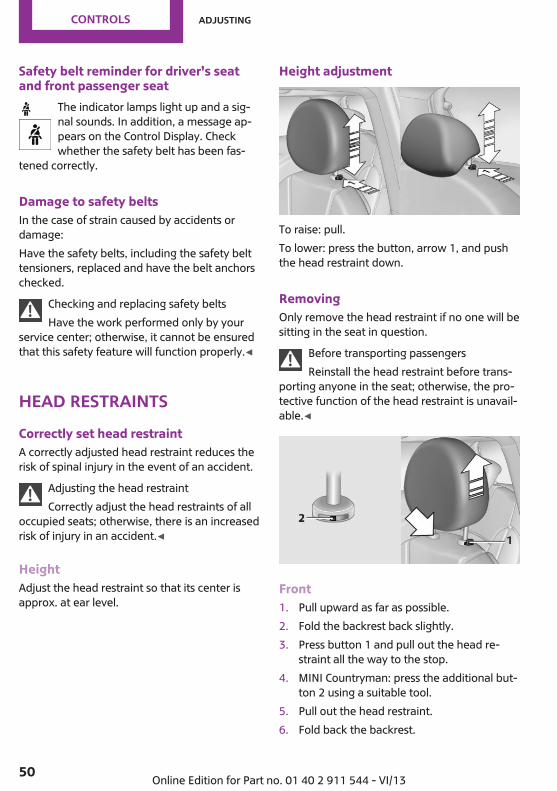
Height adjustment
To raise: pull.To lower: press the button, arrow 1, and pushthe head restraint down.
RemovingOnly remove the head restraint if no one will besitting in the seat in question.
Before transporting passengersReinstall the head restraint before trans‐
porting anyone in the seat; otherwise, the pro‐tective function of the head restraint is unavail‐able.◀
Front1. Pull upward as far as possible.2. Fold the backrest back slightly.3. Press button 1 and pull out the head re‐
straint all the way to the stop.4. MINI Countryman: press the additional but‐
ton 2 using a suitable tool.5. Pull out the head restraint.6. Fold back the backrest.
Seite 50
Controls Adjusting
50 Online Edition for Part no. 01 40 2 911 544 - VI/13

Rear1. Pull upward as far as possible.2. Fold the backrest forward slightly.3. Press button 1 and pull out the head re‐
straint all the way to the stop.4. Press the additional button 2 using a suita‐
ble tool.5. Pull out the head restraint completely.6. Fold back the rear seat backrest.
MirrorsExterior mirrors
General informationThe mirror on the passenger side is morecurved than the driver's mirror.
Estimating distances correctlyObjects reflected in the mirror are closer
than they appear. Do not estimate the distanceto the traffic behind you based on what you seein the mirror, as this will increase your risk of anaccident.◀
At a glance
1 Adjusting2 Selecting the left/right mirror3 Folding the mirror in and out
Selecting a mirrorTo change to the other mirror: slide themirror switch over.
Adjusting electricallyThe setting corresponds to the directionin which the button is pressed.
Adjusting manuallyIf an electrical malfunction occurs, for example,press the edges of the mirror glass.
Folding the mirror in and outPress button 3.The mirror can be folded in up to a vehiclespeed of approx. 20 mph/30 km/h.For example, this is advantageous▷ In car washes.▷ In narrow streets.▷ For folding back mirrors that were folded
away manually.Fold in the mirror in a car washBefore entering an automatic car wash,
fold in the exterior mirrors by hand or with thebutton; otherwise, they could be damaged, de‐pending on the width of the vehicle.◀
Automatic heatingBoth exterior mirrors are heated automaticallywhile the engine is running or the ignition isswitched on when the external temperature isbelow a certain value.
Seite 51
Adjusting Controls
51Online Edition for Part no. 01 40 2 911 544 - VI/13

Interior rearview mirror
To reduce the blinding effect from the rearwhen driving at night: turn the knob.
Interior rearview and exterior mirrors,automatic dimming feature
Two photocells are used for control:▷ In the mirror frame, see arrow.▷ On the back of the mirror.
For proper operation:▷ Keep the photocells clean.▷ Do not cover the area between the inside
rearview mirror and the windshield.▷ Do not apply stickers to the windshield in
front of the mirror.
Steering wheelAdjusting
Do not adjust while drivingDo not adjust the steering wheel while
driving; otherwise, an unexpected movementcould result in an accident.◀
1. Fold the lever down.
2. Move the steering wheel to the preferredheight and angle to suit your seating posi‐tion.
3. Fold the lever back.Do not use force to swing the lever back.Do not use force to swing the lever back
up; otherwise, the mechanism will be dam‐aged.◀
Seite 52
Controls Adjusting
52 Online Edition for Part no. 01 40 2 911 544 - VI/13

Transporting children safelyVehicle equipmentThis chapter describes all series equipment aswell as country-specific and special equipmentoffered for this model series.Therefore, it alsodescribes equipment that may not be found inyour vehicle, for instance due to the selectedspecial equipment or the country version. Thisalso applies to safety-related functions and sys‐tems.
The right place for chil‐drenNotes
Children in the vehicleDo not leave children unattended in the
vehicle; otherwise, they could endanger them‐selves and other persons, e.g., by opening thedoors.◀
Children should always be in the rearAccident research shows that the safest placefor children is on the rear seat.
Transporting children in the rearTransport children younger than 13 years
of age or shorter than 5 ft/150 cm in the rearonly, using child restraint fixing systems suita‐ble for the age, weight, and height of the child;otherwise, there is an increased risk of injury inan accident.Children 13 years of age or older must wear asafety belt as soon as a suitable child restraintfixing system can no longer be used, due totheir age, weight and size.◀
Installing child seatsOnly install child seats in the rear when
the rear seat backrest is folded all the way backand engaged; otherwise, there is an increasedrisk of injury in an accident.◀
Children on the front passenger seat
Front passenger airbagsShould it be necessary to use a child restraintfixing system on the front passenger seat,make sure that the front and side airbags onthe front passenger side are deactivated, referto page 83.
Deactivating the front passenger airbagsIf a child restraint fixing system is used in
the front passenger seat, the front passengerairbags must be deactivated; otherwise, thereis an increased risk of injury to the child whenthe airbags are triggered, even with a child re‐straint fixing system.◀
Installing child re‐straint fixing systemsBefore mountingMINI Countryman: before mounting a child re‐straint fixing system on the rear seats, movethe seats into the rearmost positions.Adjust the inclination of the center backrest tothat of the respective outer backrest.After mounting the child restraint fixing systemon the respective outer rear seat, adjust thebackrest forward, if necessary, to ensure thatthe backrest is in contact with the child re‐straint fixing system. Rear seat backrests, referto page 110.
Seite 53
Transporting children safely Controls
53Online Edition for Part no. 01 40 2 911 544 - VI/13

NotesManufacturer's information for child re‐straint fixing systems
To select, mount and use child restraint fixingsystems, observe the information provided bythe system manufacturer; otherwise, the pro‐tective effect can be impaired.◀
On the front passenger seat
Deactivating the airbagsAfter installing a child restraint fixing system onthe front passenger seat, ensure that the front,side, and knee airbags on the front passengerside are deactivated.
Deactivating the front passenger airbagsIf a child restraint fixing system is used in
the front passenger seat, the front passengerairbags must be deactivated; otherwise, thereis an increased risk of injury to the child whenthe airbags are triggered, even with a child re‐straint fixing system.◀
Seat position and heightBefore installing a child restraint fixing system,move the front passenger seat as far back aspossible and adjust its height to the highest po‐sition to obtain the best possible position forthe belt and to offer optimal protection in theevent of an accident.Do not change this seat position once it hasbeen set.
Child seat security
The graphic shows the MINI Countryman as anexample.The rear safety belts and the safety belt for thefront passenger can be locked to prevent ex‐tension in order to permit attachment of childrestraint fixing systems.
To lock the safety belt1. Secure the child restraint fixing system with
the belt.2. Pull out the belt webbing completely.3. Allow the belt webbing to be pulled in and
pull it taut against the child restraint fixingsystem.
The safety belt is locked.
To unlock the safety belt1. Open the belt buckle.2. Remove the child restraint fixing system.3. Allow the belt webbing to be pulled in com‐
pletely.Center safety belt: unlock belt buckle 3 inaddition, refer to page 49.Guide the safety belt to the holder on theheadliner.
LATCH child restraint fix‐ing systemLATCH: Lower Anchors and Tethers for Children.
Seite 54
Controls Transporting children safely
54 Online Edition for Part no. 01 40 2 911 544 - VI/13

NotesManufacturer's information for LATCHchild restraint fixing systems
To mount and use the LATCH child restraint fix‐ing systems, observe the operating and safetyinformation from the system manufacturer;otherwise, the level of protection may be re‐duced.◀
Mounts for the lower LATCH anchorsThe lower anchors may be used to attach theCRS to the vehicle seat up to a combined childand CRS weight of 65 lb/30 kg when the child isrestrained by the internal harnesses.
Correctly engage the lower LATCH an‐chors
Make sure that the lower LATCH anchors haveproperly engaged and that the child restraintfixing system is resting snugly against the back‐rest; otherwise, the degree of protection of‐fered may be reduced.◀
Before installing the child seat, pull the belt outof the area for the child restraint fixing system.
MINI Countryman
The mounts for the lower LATCH anchors arelocated at the points indicated by the arrows.
MINI Paceman
The mounts for the lower LATCH anchors arelocated at the points indicated by the arrows.
Mounting LATCH child restraint fixingsystems1. Mount the child restraint fixing system; re‐
fer to the operating instructions of the sys‐tem.
2. Ensure that both LATCH anchors are prop‐erly connected.
Child restraint fixingsystems with an upper re‐taining strapMounting points
LATCH mounting eyesOnly use the mounting eyes for the upper
LATCH retaining strap to secure child restraintfixing systems; otherwise, the mounting eyescould be damaged.◀
There are two additional mounting points forchild restraint fixing systems with an upper re‐taining strap, arrows.
Seite 55
Transporting children safely Controls
55Online Edition for Part no. 01 40 2 911 544 - VI/13

MINI Countryman
There are two additional mounting points forchild restraint fixing systems with an upper re‐taining strap, arrows.
MINI Paceman
There are two additional mounting points forchild restraint fixing systems with an upper re‐taining strap, arrows.
Guide of the upper LATCH retainingstrap
Retaining strapMake sure the upper retaining strap does
not run over sharp edges and is not twisted asit passes to the top anchor. Otherwise, thestrap will not properly secure the child restraintfixing system in the event of an accident.◀
Outer seats:
1 Direction of travel2 Head restraint3 Cargo area floor4 Hook for upper retaining strap5 Mounting point6 Backrest7 Upper retaining strap of child restraint fix‐
ing system
MINI Countryman, center seat
1 Direction of travel2 Head restraint3 Hook for upper retaining strap4 Mounting point5 Cargo area floor6 Backrest7 Upper retaining strap of child restraint fix‐
ing system
Seite 56
Controls Transporting children safely
56 Online Edition for Part no. 01 40 2 911 544 - VI/13

Attaching the upper retaining strap tothe mounting point1. Slide the head restraint upward.2. Center seat: fold the cargo area floor for‐
ward.3. Guide the upper retaining strap between
the supports of the head restraint.4. Attach the upper retaining strap to the
mounting point with the hook.5. Slide the head restraint into the bottom po‐
sition.6. Pull the upper retaining strap taut.
MINI Countryman: lock‐ing doors and windowsRear doors
Push the locking lever on the rear doors down.The door can now be opened from the outsideonly.
Safety switch for power windowThis locks the rear window switches so that thewindows cannot be operated from the rear.Press the safety switch, refer to page 44.
Seite 57
Transporting children safely Controls
57Online Edition for Part no. 01 40 2 911 544 - VI/13
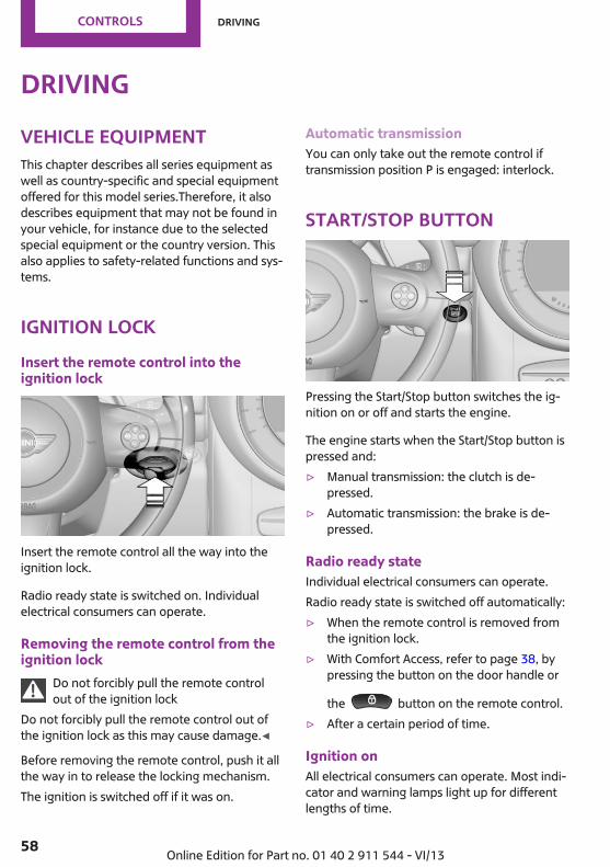
DrivingVehicle equipmentThis chapter describes all series equipment aswell as country-specific and special equipmentoffered for this model series.Therefore, it alsodescribes equipment that may not be found inyour vehicle, for instance due to the selectedspecial equipment or the country version. Thisalso applies to safety-related functions and sys‐tems.
Ignition lockInsert the remote control into theignition lock
Insert the remote control all the way into theignition lock.
Radio ready state is switched on. Individualelectrical consumers can operate.
Removing the remote control from theignition lock
Do not forcibly pull the remote controlout of the ignition lock
Do not forcibly pull the remote control out ofthe ignition lock as this may cause damage.◀
Before removing the remote control, push it allthe way in to release the locking mechanism.The ignition is switched off if it was on.
Automatic transmissionYou can only take out the remote control iftransmission position P is engaged: interlock.
Start/Stop button
Pressing the Start/Stop button switches the ig‐nition on or off and starts the engine.
The engine starts when the Start/Stop button ispressed and:▷ Manual transmission: the clutch is de‐
pressed.▷ Automatic transmission: the brake is de‐
pressed.
Radio ready stateIndividual electrical consumers can operate.Radio ready state is switched off automatically:▷ When the remote control is removed from
the ignition lock.▷ With Comfort Access, refer to page 38, by
pressing the button on the door handle or
the button on the remote control.▷ After a certain period of time.
Ignition onAll electrical consumers can operate. Most indi‐cator and warning lamps light up for differentlengths of time.
Seite 58
Controls Driving
58 Online Edition for Part no. 01 40 2 911 544 - VI/13

To save battery power when the engine is off,switch off the ignition and any unnecessaryelectronic systems/power consumers.
Radio ready state and ignition offAll indicator and warning lamps in the displaysgo out.The ignition switches off automatically whenthe driver's door is opened. Pressing the Start/Stop button again switches the ignition backon.For example, the ignition is not switched off inthe following situations:▷ Depress the clutch or brake pedal.▷ The low beams are switched on
Starting the engineGeneral information
Enclosed areasDo not let the engine run in enclosed
areas; otherwise, breathing of exhaust fumesmay lead to loss of consciousness and death.The exhaust gases contain carbon monoxide,an odorless and colorless but highly toxic gas.◀
Unattended vehicleDo not leave the car unattended with the
engine running; otherwise, it presents a poten‐tial source of danger.Before leaving the car with the engine running,shift to neutral or engage transmission posi‐tion P and set the handbrake firmly; otherwise,the vehicle may begin to roll.◀
Frequent starting in quick successionAvoid repeated futile attempts at starting
the car and avoid starting the car frequently inquick succession. Otherwise, the fuel is notburned or is inadequately burned, and there isthe danger of overheating and damaging thecatalytic converter.◀
Do not wait for the engine to warm-up whilethe vehicle remains stationary; start drivingright away, but at moderate engine speeds.Do not depress the accelerator when startingthe engine.
Starting the engine
Manual transmissionRemote control in the ignition lock or, withComfort Access, inside the vehicle, refer topage 38.
1. Depress the brake pedal.2. Depress the clutch pedal.3. Press the Start/Stop button.The ignition is activated automatically for a cer‐tain time and is stopped as soon as the enginestarts.
Automatic transmissionRemote control in the ignition lock or, withComfort Access, inside the vehicle, refer topage 38.
1. Depress the brake pedal.2. Move the selector lever to position P or N.3. Press the Start/Stop button.The ignition is activated automatically for a cer‐tain time and is stopped as soon as the enginestarts.
Seite 59
Driving Controls
59Online Edition for Part no. 01 40 2 911 544 - VI/13

Engine stopGeneral information
Take the remote control with youTake the remote control with you when
leaving the vehicle so that children, for exam‐ple, cannot operate the windows and injurethemselves.◀
Set the handbrake and further secure thevehicle as required
Set the handbrake firmly when parking; other‐wise, the vehicle may roll. On steep upwardand downward inclines, further secure the ve‐hicle, for example, by turning the steeringwheel in the direction of the curb.◀
Before driving into a car washTo make it possible for the vehicle to roll in anautomatic car wash, follow the information onWashing in automatic car washes, refer topage 254.
Switching off the engine
Manual transmission1. With the vehicle at a standstill, press the
Start/Stop button.2. Shift into first gear or reverse.3. Set the handbrake firmly.4. Remove the remote control from the igni‐
tion lock.
Automatic transmission1. Engage transmission position P with the ve‐
hicle stopped.2. Press the Start/Stop button.3. Set the handbrake firmly.4. Remove the remote control from the igni‐
tion lock.
HandbrakeThe conceptThe handbrake is primarily intended to preventthe vehicle from rolling while parked; it brakesthe rear wheels.Also follow the instructions under Switching offthe engine, refer to page 60.
SettingThe lever engages automatically.
Releasing
Pull up slightly, press the button, and lower thelever.
NotesUsing the handbrake while drivingIf it should become necessary to use the
handbrake while driving, do not pull the hand‐brake too forcefully. Keep the button on thehandbrake lever pressed at all times.Excessive application of the handbrake canblock the rear wheels and lead to fishtailing ofthe vehicle.◀
The brake lamps do not light up when thehandbrake is pulled.
Seite 60
Controls Driving
60 Online Edition for Part no. 01 40 2 911 544 - VI/13

Turn signal, high beams,headlamp flasher
1 Turn signal2 Switching on the high beams3 Switching off the high beams/headlamp
flasher
Turn signalPress the lever beyond the resistance point.To switch off manually, press the lever to theresistance point.Unusually rapid flashing of the indicator lampindicates that a turn signal bulb has failed.
Signaling a turn brieflyPress the lever to the resistance point and holdit there for as long as you want the turn signalto flash.
Triple turn signal activationPress the lever to the resistance point.The turn signal flashes three times.This function can be activated or deactivated:
1. "Settings"2. "Lighting"
3. "Triple turn signal"
The setting is stored for the remote control cur‐rently in use.
Washer/wiper systemNotes
Do not switch on the wipers if frozenDo not switch on the wipers if they are
frozen onto the windshield; otherwise, thewiper blades and the windshield wiper motormay be damaged.◀
Do not use the wipers on a dry windshieldDo not use the wipers on a dry wind‐
shield; otherwise, the wiper blades may wearmore rapidly or become damaged.◀
At a glance
1 Switching on wipers2 Switching off wipers or brief wipe
Seite 61
Driving Controls
61Online Edition for Part no. 01 40 2 911 544 - VI/13

3 Activating/deactivating intermittent wipe orthe rain sensor
4 Cleaning the windshield and headlamps
Switching on wipersPress the wiper lever upward, arrow 1.The lever automatically returns to its initial po‐sition when released.
Normal wiper speedPress up once.The system switches to operation in the inter‐mittent mode when the vehicle is stationary.
Fast wiper speedPress up twice or press once beyond the resist‐ance point.The system switches to normal speed when thevehicle is stationary.
Switching off wipers or brief wipePress the wiper lever down, arrow 2.The lever automatically returns to its initial po‐sition when released.▷ Brief wipe: press down once.▷ To switch off normal wipe: press down
once.▷ To switch off fast wipe: press down twice.
Intermittent wipe or rain sensorIf the car is not equipped with a rain sensor, theintermittent-wipe time is a preset.If the car is equipped with a rain sensor, thetime between wipes is controlled automaticallyand depends on the intensity of the rainfall.The rain sensor is mounted on the windshield,directly in front of the interior rearview mirror.
Deactivate the rain sensor in car washesDeactivate the rain sensor when passing
through an automatic car wash; otherwise,damage could be caused by undesired wiperactivation.◀
Activating intermittent wipe or rainsensorPress the button, arrow 3.
The symbol is shown in the tachometer.
Setting the sensitivity of the rain sensor1. Switch on the ignition, refer to page 58.2. Press the button on the turn indicator lever
repeatedly until "SET/INFO" is displayed.
3. Press and hold the button until the displaychanges.
4. Press the button repeatedly until the sym‐bol and "SET" are displayed.
Seite 62
Controls Driving
62 Online Edition for Part no. 01 40 2 911 544 - VI/13
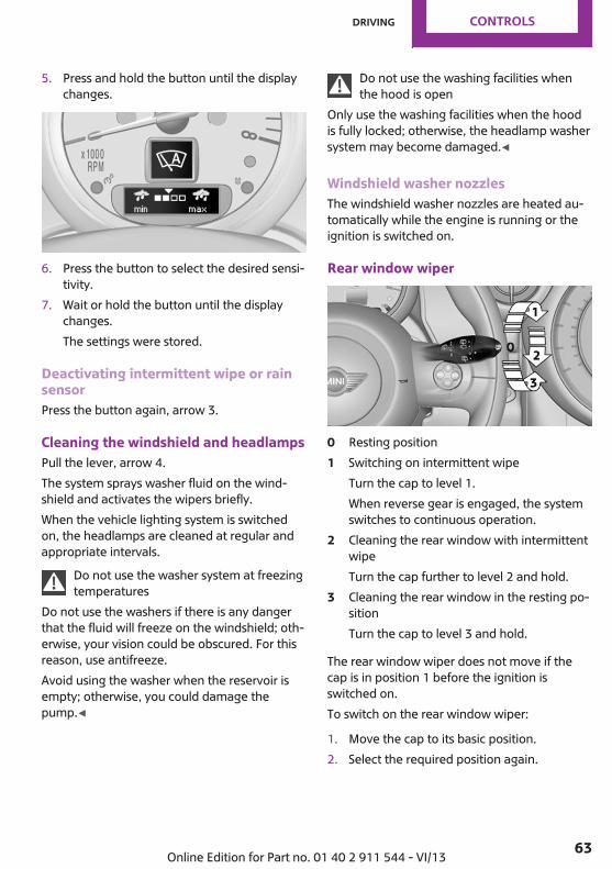
5. Press and hold the button until the displaychanges.
6. Press the button to select the desired sensi‐tivity.
7. Wait or hold the button until the displaychanges.The settings were stored.
Deactivating intermittent wipe or rainsensorPress the button again, arrow 3.
Cleaning the windshield and headlampsPull the lever, arrow 4.The system sprays washer fluid on the wind‐shield and activates the wipers briefly.When the vehicle lighting system is switchedon, the headlamps are cleaned at regular andappropriate intervals.
Do not use the washer system at freezingtemperatures
Do not use the washers if there is any dangerthat the fluid will freeze on the windshield; oth‐erwise, your vision could be obscured. For thisreason, use antifreeze.Avoid using the washer when the reservoir isempty; otherwise, you could damage thepump.◀
Do not use the washing facilities whenthe hood is open
Only use the washing facilities when the hoodis fully locked; otherwise, the headlamp washersystem may become damaged.◀
Windshield washer nozzlesThe windshield washer nozzles are heated au‐tomatically while the engine is running or theignition is switched on.
Rear window wiper
0 Resting position1 Switching on intermittent wipe
Turn the cap to level 1.When reverse gear is engaged, the systemswitches to continuous operation.
2 Cleaning the rear window with intermittentwipeTurn the cap further to level 2 and hold.
3 Cleaning the rear window in the resting po‐sitionTurn the cap to level 3 and hold.
The rear window wiper does not move if thecap is in position 1 before the ignition isswitched on.To switch on the rear window wiper:
1. Move the cap to its basic position.2. Select the required position again.
Seite 63
Driving Controls
63Online Edition for Part no. 01 40 2 911 544 - VI/13

Do not use the washing mechanismswhen the washer fluid reservoir is empty
Do not use washing mechanisms when thewasher fluid reservoir is empty, otherwise youwill damage the washer pump.◀
Washer fluidGeneral information
Antifreeze for washer fluidAntifreeze is flammable and can cause in‐
juries if used improperly.Therefore, keep it away from sources of igni‐tion.Only keep it in the closed original container andinaccessible to children.Follow the notes and instructions on the con‐tainer.United States: The washer fluid mixture ratio isregulated by the U.S. EPA and many individualstates; do not exceed the allowable washerfluid dilution ratios limits that apply. Follow theusage instructions on the washer fluid con‐tainer. Use BMW's Windshield Washer Concen‐trate or the equivalent.◀
Washer fluid reservoirAdding washer fluidOnly add washer fluid when the engine is
cool, and then close the cover completely toavoid contact between the washer fluid andhot engine parts.Otherwise, there is the danger of fire and a riskto personal safety if the fluid is spilled.◀
All washer nozzles are supplied from one reser‐voir.
The recommended minimum filling quantity is0.2 US gal/1 liter.Fill with a mixture of window washing concen‐trate and water; if needed, add antifreeze ac‐cording to the manufacturer instructions.Mix the washer fluid before adding to maintainthe correct mixing ratio.Do not fill in undiluted window washing con‐centrate and do not fill in pure water; this coulddamage the washer system.Do not mix window washing concentrate fromdifferent manufacturers; this could cause thewasher nozzles to clog.
Manual transmission
Pay attention to the shift planeWhen shifting into 5th or 6th gear, push
the gearshift lever to the right; otherwise inad‐vertent shifting into the 3rd or 4th gear couldlead to engine damage.◀
Seite 64
Controls Driving
64 Online Edition for Part no. 01 40 2 911 544 - VI/13

Reverse gearSelect only when the vehicle is stationary. Whenthe gearshift lever is pressed to the left, a slightresistance needs to be overcome.
Automatic transmissionwith SteptronicIn addition to the fully automatic mode, gearscan also be shifted manually using Steptronic,refer to page 66.
Parking the vehicleSecure the vehicleBefore leaving the vehicle with the en‐
gine running, move the selector lever to posi‐tion P and set the handbrake; otherwise, thevehicle will begin moving.◀
Disengaging the remote controlTo remove the remote control from the ignitionlock, first move the selector lever to position Pand switch off the engine: interlock. Removethe remote control from the ignition lock, referto page 58.
Selector lever positionsP R N D M/S + –
Displays in the tachometer
The selector lever position is displayed and theengaged gear, such as M4, is displayed inmanual mode.
Changing selector lever positions▷ With the ignition switched on or the engine
running, the selector lever can be movedout of position P.
▷ When the vehicle is stationary, step on thebrake before shifting out of P or N; other‐wise, the selector lever is locked: shiftlock.
Press on the brake pedal until youstart driving
To prevent the vehicle from creeping afteryou select a driving position, maintain pres‐sure on the brake pedal until you are readyto start.◀
A lock prevents accidental shifting into selectorlever positions R and P.To override the lock, press the button on thefront of the selector lever, see arrow.
P ParkSelect only when the vehicle is stationary. Thefront wheels are blocked.
R is ReverseSelect only when the vehicle is stationary.
N is NeutralFor example, engage this position in a carwash. The vehicle can roll.
D Drive, automatic positionPosition for normal vehicle operation. All for‐ward gears are selected automatically.
Seite 65
Driving Controls
65Online Edition for Part no. 01 40 2 911 544 - VI/13

Under normal operating conditions, fuel con‐sumption is lowest when you are driving in po‐sition D.
KickdownKickdown is used to achieve maximum drivingperformance. Press on the accelerator beyondthe resistance point at the full throttle position.
Sport program and manual mode M/S
Activating the Sport program
Move the selector lever from position D towardthe left into the M/S shifting slot.
The Sport program is activated and DS is dis‐played. This position is recommended for a per‐formance-oriented driving style.To deactivate the Sport program or manualmode M/S, move the selector lever to the rightinto position D.
Activating the M/S manual modeMove the selector lever from position D towardthe left into the M/S shifting slot.Push the selector lever forward or backward.Manual mode becomes active and the gear ischanged.The tachometer displays the engaged gear,e. g. M1.▷ To shift up: press the selector lever back‐
ward.▷ To shift down: press the selector lever for‐
ward.
The vehicle only shifts up or down at appropri‐ate engine and road speeds, e.g., it does notshift down if the engine speed is too high. Theselected gear is briefly displayed in the instru‐ment panel, followed by the current gear.
Shifting gears using the shift paddleson the steering wheelThe shift paddles on the steering wheel allowyou to shift gears quickly while keeping bothhands on the steering wheel.▷ When the shift paddles on the steering
wheel are used to shift gears while in auto‐matic mode, the transmission switches tomanual mode.
▷ If the shift paddles are not used to acceler‐ate or shift gears for a certain amount oftime, the transmission switches back to au‐tomatic mode.
If the selector lever is in the M/S gear plane,manual mode remains active.
▷ Pull one of the two shift paddles:The transmission shifts up.
▷ Press one of the two shift paddles:The transmission shifts down.
The vehicle only shifts up or down at appropri‐ate engine and road speeds, e.g., it does notshift down if the engine speed is too high. Theselected gear is briefly displayed in the instru‐ment panel, followed by the current gear.
Seite 66
Controls Driving
66 Online Edition for Part no. 01 40 2 911 544 - VI/13

Manually unlocking the selector leverlockIf the selector lever is locked in position P al‐though the ignition is switched on, the brake isdepressed, and the button on the selector leveris pressed, the selector lever lock can be over‐ridden:
1. Switch off the ignition.2. Unclip the sleeve of the selector lever.3. Pull the sleeve up over the selector lever
until the sleeve is inside out.Pull off the plug-in cable connector if nec‐essary.
4. Insert the pulling hook 1 into the loop onthe passenger side.The pulling hook is found in the vehicledocument portfolio or in the pouch of thewheel change set, refer to page 245.
5. Pull the loop upward.6. Move the selector lever into the desired po‐
sition, pressing the button on the front ofthe selector lever.
Set the handbrakeBefore manually unlocking the selector
lever lock, pull the handbrake firmly; otherwise,the vehicle may roll away and cause personalinjury or property damage.◀
Seite 67
Driving Controls
67Online Edition for Part no. 01 40 2 911 544 - VI/13

DisplaysVehicle equipmentThis chapter describes all series equipment aswell as country-specific and special equipmentoffered for this model series.Therefore, it alsodescribes equipment that may not be found inyour vehicle, for instance due to the selectedspecial equipment or the country version. Thisalso applies to safety-related functions and sys‐tems.
Odometer, external tem‐perature display, clockAt a glance
1 Current speed2 Odometer, trip odometer, external temper‐
ature, time3 Resetting the trip odometer
Press the button on the turn indicator lever toopen information in display area 2.The following information is displayed consecu‐tively:▷ Trip odometer▷ Time▷ External temperature
Trip odometerTo display the trip odometer: briefly pressknob 3.To reset the trip odometer: press knob 3 whilethe trip odometer is being displayed and the ig‐nition is switched on.
TimeSet the time, refer to page 72.
External temperature, externaltemperature warningIf the display drops to +37 ℉/+3 ℃, a signalsounds and a warning lamp lights up. There isthe increased danger of ice.
Ice on roadsEven at temperatures above
+37 ℉/+3 ℃, there can be a risk of ice onroads.Therefore, drive carefully on bridges and shadyroads, for example, to avoid the increased dan‐ger of an accident.◀
Units of measureTo set the respective units of measure, miles orkm for the odometer and ℃ or ℉ for the exter‐nal temperature, refer to page 72.
Seite 68
Controls Displays
68 Online Edition for Part no. 01 40 2 911 544 - VI/13

Tachometer
It is imperative that you avoid engine speeds inthe red warning field. In this range, the fuelsupply is interrupted to protect the engine.
Coolant temperatureA warning lamp will come on if the coolant, andtherefore the engine, becomes too hot. In addi‐tion, a message will appear on the Control Dis‐play.Check the coolant level, refer to page 236.
Fuel gauge
The arrow next to the fuel pump symbol on thefuel gauge indicates the side of the vehicle withthe fuel filler flap.The vehicle inclination may cause the display tovary.
Notes on refueling, refer to page 216.Filling capacities, refer to page 263.
RangeAfter the reserve range is reached:▷ The remaining LEDs change from orange to
red, arrow.▷ A message is briefly displayed on the Con‐
trol Display.▷ The remaining range is shown on the tach‐
ometer.▷ When a dynamic driving style is used, such
as when corners are taken rapidly, enginefunctions are not ensured.
The message appears continuously below arange of approx. 30 miles/50 km.
Refuel promptlyAt the latest, refuel at a range below
30 miles/50 km; otherwise, the engine functionis not ensured and damage may occur.◀
ComputerOpening information in the tachometer
Press the button on the turn indicator lever.
Overview of the informationThe following information is displayed consecu‐tively by repeatedly pressing the button on theturn indicator lever:▷ Range.▷ Average fuel consumption.▷ Current fuel consumption.▷ Average speed.
Seite 69
Displays Controls
69Online Edition for Part no. 01 40 2 911 544 - VI/13
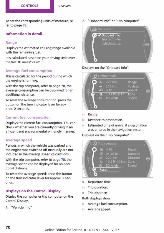
To set the corresponding units of measure, re‐fer to page 72.
Information in detail
RangeDisplays the estimated cruising range availablewith the remaining fuel.It is calculated based on your driving style overthe last 18 miles/30 km.
Average fuel consumptionThis is calculated for the period during whichthe engine is running.With the trip computer, refer to page 70, theaverage consumption can be displayed for anadditional distance.To reset the average consumption: press thebutton on the turn indicator lever for ap‐prox. 2 seconds.
Current fuel consumptionDisplays the current fuel consumption. You cancheck whether you are currently driving in anefficient and environmentally-friendly manner.
Average speedPeriods in which the vehicle was parked andthe engine was switched off manually are notincluded in the average speed calculations.With the trip computer, refer to page 70, theaverage speed can be displayed for an addi‐tional distance.To reset the average speed: press the buttonon the turn indicator lever for approx. 2 sec‐onds.
Displays on the Control DisplayDisplay the computer or trip computer on theControl Display.
1. "Vehicle Info"
2. "Onboard info" or "Trip computer"
Displays on the "Onboard info":
▷ Range.▷ Distance to destination.▷ Estimated time of arrival if a destination
was entered in the navigation system.Displays on the "Trip computer":
▷ Departure time.▷ Trip duration.▷ Trip distance.Both displays show:▷ Average fuel consumption.▷ Average speed.
Seite 70
Controls Displays
70 Online Edition for Part no. 01 40 2 911 544 - VI/13

Resetting the fuel consumption andspeedResetting the values for average speed andaverage fuel consumption:
1. Select the respective menu item and pressthe MINI joystick.
2. Press the MINI joystick again to confirmyour selection.
Resetting the trip computerResetting all values:
1. "Vehicle Info"2. "Trip computer"3. "Reset"
Settings and informationOperating conceptSome settings and information can only be cre‐ated or opened while the ignition is switchedon, the vehicle is standing, and the doors areclosed.
1 Button for:▷ Selecting the display.▷ Setting values.▷ Confirming the selected display or set
values.▷ Calling up computer information 69.
Symbol Function
Set the rain sensor, refer topage 62.
Open Check-Control, refer topage 75.
Exit the menu.
Exiting displays
1. Press the button on the turn indicator leverrepeatedly until "HOME" is displayed.
2. Hold the button down.The current speed is displayed again.Displays are also exited if no entries are madewithin approx. 8 seconds.
Seite 71
Displays Controls
71Online Edition for Part no. 01 40 2 911 544 - VI/13

Next setting or information
1. Within a setting or information display,press the button on the turn indicator leverrepeatedly until "NEXT" is displayed.
2. Hold the button down.Direct change to the next setting or piece of in‐formation.
Units of measureThe units of measure, such as for fuel consump‐tion, route/distance, and temperature, can bechanged. The settings are stored for the remotecontrol currently in use.
1. "Settings"2. "Language/Units"
3. Select the desired menu item.4. Select the desired unit.
ClockSetting the time1. "Settings"
2. "Time/Date"
3. "Time:"
4. Turn the MINI joystick to set the hours andpress the MINI joystick.
5. Turn the MINI joystick to set the minutesand press the MINI joystick.
The time is stored.
Setting the time format1. "Settings"2. "Time/Date"
Seite 72
Controls Displays
72 Online Edition for Part no. 01 40 2 911 544 - VI/13

3. "Format:"4. Select the desired format.The time format is stored.The settings are stored for the remote controlcurrently in use.
Setting the time zone1. "Settings"2. "Time/Date"3. "Time zone:"4. Turn the MINI joystick until the desired time
zone is displayed and press the MINI joy‐stick.
The time zone is stored.
DateSetting the date1. "Settings"2. "Time/Date"3. "Date:"4. Turn the MINI joystick until the desired day
is displayed and press the MINI joystick.5. Make the necessary settings for the month
and year.The date is stored.
Setting the date format1. "Settings"2. "Time/Date"
3. "Format:"4. Select the desired format.
The settings are stored for the remote controlcurrently in use.
Settings on the ControlDisplayLanguage
Setting the language1. "Settings"2. "Language/Units"3. "Language:"
4. Select the desired language.The setting is stored for the remote control cur‐rently in use.
Setting the voice dialogVoice dialog for the voice activation system, re‐fer to page 27.
Seite 73
Displays Controls
73Online Edition for Part no. 01 40 2 911 544 - VI/13

BrightnessThe brightness is automatically adapted to theambient lighting conditions. However, the basicsetting can be changed when the low beamsare switched on.
1. "Settings"2. "Control display"3. "Brightness"
4. Turn the MINI joystick until the desired set‐ting is selected.
5. Press the MINI joystick.The setting is stored for the remote control cur‐rently in use.Depending on the light conditions, the bright‐ness control may not be clearly visible.
Service requirements
The remaining driving distance and the date ofthe next scheduled service are displayed brieflyimmediately after you start the engine orswitch on the ignition.
The current service requirements can be readout from the remote control by the service spe‐cialist.
Detailed information on servicerequirementsMore information on the scope of service re‐quired can be displayed on the Control Display.
1. "Vehicle Info"2. "Vehicle status"
3. "Service required"Required maintenance procedures and legallymandated inspections are displayed.Additional information can be displayed oneach entry:Select the entry and press the MINI joystick.To exit from the menu:Move the MINI joystick to the left.
Symbols
Symbols Description
No service is currently required.
The deadline for service or a le‐gally mandated inspection isapproaching.
The service deadline has al‐ready passed.
Seite 74
Controls Displays
74 Online Edition for Part no. 01 40 2 911 544 - VI/13

Entering appointment datesEnter the dates for the required inspections.Make sure the date on the Control Display is setcorrectly.
1. "Vehicle Info"2. "Vehicle status"3. "Service required"
4. "§ Vehicle inspection"
5. Open the menu for entering the deadline.6. "Date:"7. Create the settings.8. Press the MINI joystick to apply the setting.
The year is highlighted.9. Turn the MINI joystick to create the setting.10. Press the MINI joystick to apply the setting.
The date entry is stored.To exit from the menu:Move the MINI joystick to the left.
Check ControlThe conceptThe Check Control monitors vehicle functionsand alerts you to any malfunctions in the sys‐tems being monitored.A Check Control message consists of indicatorand warning lamps in the instrument clusterand, in some circumstances, an acoustic signaland text messages at the top of the Control Dis‐play.
Indicator/warning lamps
The indicator and warning lamps can light up ina variety of combinations and colors in displayarea 1 or 2.
Several of the lamps are checked for properfunctioning and light up temporarily when theengine is started or the ignition is switched on.
The symbol indicates that Check Controlmessages have been stored. The Check Controlmessages can be displayed later.
Seite 75
Displays Controls
75Online Edition for Part no. 01 40 2 911 544 - VI/13

Text messagesText messages at the upper edge of the ControlDisplay in combination with a symbol in the in‐strument cluster explain a Check Control mes‐sage and the meaning of the indicator andwarning lamps.
Supplementary text messagesAdditional information, such as on the cause ofa fault or the required action, can be called upvia Check Control.
In urgent cases, this information will be shownas soon as the corresponding lamp comes on.
Hiding Check Control messages
Press the button on the turn indicator lever.
Some Check Control messages are displayedcontinuously and are not cleared until the mal‐function is eliminated. If several malfunctionsoccur at once, the messages are displayed con‐secutively.
They are marked with the symbolshown here.
Other Check Control messages are hidden au‐tomatically after approx. 20 seconds. However,they are stored and can be displayed againlater.
They are marked with the symbolshown here.
Viewing stored Check Control messagesThe stored Check Control messages can only bedisplayed while the driver's door is closed.
1. Press the button on the turn indicator leverrepeatedly until "SET/INFO" is displayed.
2. Press and hold the button until the displaychanges.
3. Press the button repeatedly until the corre‐sponding symbol and "CHECK INFO" ap‐pear on the display.
4. Press and hold the button.If there is no Check Control message, this isindicated by "CHECK OK“.If a Check Control message has beenstored, the corresponding message is dis‐played.
Seite 76
Controls Displays
76 Online Edition for Part no. 01 40 2 911 544 - VI/13

The text message is also displayed on theControl Display.
5. Press the button to check for other mes‐sages.
Displaying on the Control Display1. "Vehicle Info"2. "Vehicle status"3. "Check Control"
4. Select the text message.
Seite 77
Displays Controls
77Online Edition for Part no. 01 40 2 911 544 - VI/13

LampsVehicle equipmentThis chapter describes all series equipment aswell as country-specific and special equipmentoffered for this model series.Therefore, it alsodescribes equipment that may not be found inyour vehicle, for instance due to the selectedspecial equipment or the country version. Thisalso applies to safety-related functions and sys‐tems.
At a glance
0 Lamps off / daytime running lights1 Parking lamps and daytime running lights2 Low-beam headlamps and welcome lamps3 Automatic headlamp control, Adaptive
Light Control, daytime running lights, andwelcome lamps
Parking lamps/lowbeams, headlamp con‐trolGeneral informationWhen the driver's door is opened with the igni‐tion switched off, the exterior lighting is auto‐matically switched off when the light switch isin position 0, 2, or 3.
Switch on the parking lamps if necessary,switch position 1.
Parking lampsSwitch position 1: the vehicle lamps light up onall sides.Do not use the parking lamps for extended pe‐riods; otherwise, the battery may become dis‐charged and it would then be impossible tostart the engine.When parking, it is preferable to switch on theone-sided roadside parking lamps, refer topage 79.
Low beamsSwitch position 2: the low beams are lit whenthe ignition is switched on.
Automatic headlamp controlSwitch position 3: the low beams are switchedon and off automatically depending on the am‐bient light, e.g., in tunnels, in twilight, or ifthere is precipitation. Adaptive Light Control isactive.A blue sky with the sun low on the horizon cancause the lights to be switched on.The low beams remain switched on independ‐ent of the ambient lighting conditions whenyou switch on the front fog lamps.
Personal responsibilityThe automatic headlamp control cannot
serve as a substitute for your personal judg‐ment in determining when the lamps should beswitched on in response to ambient lightingconditions.For example, the sensors are unable to detectfog or hazy weather. To avoid safety risks, youshould always switch on the lamps manuallyunder these conditions.◀
Seite 78
Controls Lamps
78 Online Edition for Part no. 01 40 2 911 544 - VI/13

When the daytime running lights are activated,the low beams are always switched on inswitch position 3 when the ignition is switchedon.The exterior lighting goes out automatically af‐ter the vehicle is switched off.
High beams/roadside parking lamps
1 Turn signal/roadside parking lamp2 Switching on the high beams3 Switching off the high beams/headlamp
flasher
To assist in parking, the vehicle can be illumi‐nated on one side; note the country-specificregulations.The roadside parking lamps drain the battery.Therefore, do not leave them on for undulylong periods of time; otherwise, the batterymight not have enough power to start the en‐gine.
Switching on the roadside parking lampTo switch on the roadside parking lamp on theleft or right, press the turn indicator lever up ordown after switching off the vehicle, arrow 1.
Switching off the roadside parking lampPress the lever up or down to the resistancepoint.
Daytime running lightsThe daytime running lights light up in switchposition 0, 1, or 3 when the ignition is switchedon.
The exterior lighting goes out automatically af‐ter the vehicle is switched off.In switch position 1, the parking lamps light upafter the ignition is switched off.
Activating/deactivating1. "Settings"2. "Lighting"3. "Daytime running lamps"
The setting is stored for the remote control cur‐rently in use.
Welcome lampsIf the light switch stays in switch position 2 or 3after the vehicle is switched off, the parkinglamps and the interior lamps light up for a cer‐tain period when the vehicle is unlocked.
Headlamp courtesy delay featureThe low beams stay lit for a short while afterthe ignition is switched off, if the lamps areswitched off and the headlamp flasher isswitched on.
Setting the duration1. "Settings"2. "Lighting"
Seite 79
Lamps Controls
79Online Edition for Part no. 01 40 2 911 544 - VI/13

3. "Pathway light.: s"
4. Set the duration.The setting is stored for the remote control cur‐rently in use.
Adaptive Light ControlThe conceptAdaptive Light Control is a variable headlampcontrol system that enables dynamic illumina‐tion of the road surface.Depending on the steering angle and other pa‐rameters, the light from the headlamp followsthe course of the road.
ActivatingWith the ignition switch on, turn the light switchto position 3, refer to page 78.To avoid blinding oncoming traffic, the Adap‐tive Light Control does not swivel to the driver'sside when the vehicle is at a standstill.When driving in reverse, Adaptive Light Controlis not active.
MalfunctionThe warning lamp lights up. A messageappears on the Control Display. Adap‐tive Light Control is malfunctioning or
has failed. Have the system checked as soon aspossible.
Fog lampsAt a glance
To switch on the front fog lamps: press theswitch.To switch off, press the respective switch up‐ward or downward again.
Fog lampsThe parking lamps or low beams must beswitched on. The green indicator lamp lights upwhen the front fog lamps are switched on.Depending on the vehicle equipment, the frontfog lamps are switched off when the headlampflasher or the high beams are activated.If the automatic headlamp control is activated,refer to page 78, the low beams are switchedon automatically when the front fog lamps areswitched on.
Instrument lightingThe parking lamps or low beams must beswitched on to adjust the brightness. Thebrightness is increased to a certain limit and isthen reduced again.
Seite 80
Controls Lamps
80 Online Edition for Part no. 01 40 2 911 544 - VI/13

▷ Press the button briefly: the brightnesschanges in stages.
▷ Press and hold the button: the brightnesschanges continuously.
Interior lampsThe interior lamps, the footwell lamps and thecargo area lamp are controlled automatically.To avoid draining the battery, all lamps insidethe vehicle are switched off some time after theignition is switched off.
Switching interior lamps on/offmanually
To switch the interior lamps on/off: press theswitch.
If the interior lamps are to remain switched off,press the switch for approx. 3 seconds.
Reading lampsReading lamps are located in the front next tothe interior lamp and in the rear.
Switching the reading lamps on/offFront: press the switch.Rear: press the button.
Ambient lightingThe color and brightness of the ambient light‐ing can be changed.
Press the switch forward: the color changes insteps.Press the switch back: the brightness changesin steps.
Intermediate settings and intermediate colorsare possible.For continuously changing colors of the ambi‐ent lighting, press the switch forward for morethan 10 seconds.
Seite 81
Lamps Controls
81Online Edition for Part no. 01 40 2 911 544 - VI/13
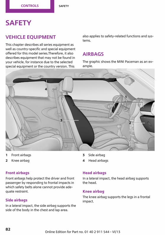
SafetyVehicle equipmentThis chapter describes all series equipment aswell as country-specific and special equipmentoffered for this model series.Therefore, it alsodescribes equipment that may not be found inyour vehicle, for instance due to the selectedspecial equipment or the country version. This
also applies to safety-related functions and sys‐tems.
AirbagsThe graphic shows the MINI Paceman as an ex‐ample.
1 Front airbags2 Knee airbag
3 Side airbag4 Head airbags
Front airbagsFront airbags help protect the driver and frontpassenger by responding to frontal impacts inwhich safety belts alone cannot provide ade‐quate restraint.
Side airbagsIn a lateral impact, the side airbag supports theside of the body in the chest and lap area.
Head airbagsIn a lateral impact, the head airbag supportsthe head.
Knee airbagThe knee airbag supports the legs in a frontalimpact.
Seite 82
Controls Safety
82 Online Edition for Part no. 01 40 2 911 544 - VI/13

Protective actionAirbags are not triggered in every impact situa‐tion, e.g., in less severe accidents or rear-endcollisions.
Information on how to ensure the opti‐mal protective effect of the airbags
▷ Keep at a distance from the airbags.▷ Always grasp the steering wheel on the
steering wheel rim, holding your hands atthe 3 o'clock and 9 o'clock positions, tokeep the danger of injury to your hands orarms as low as possible if the airbag is trig‐gered.
▷ There should be no people, animals, or ob‐jects between an airbag and a person.
▷ Do not use the cover of the front airbag onthe front passenger side as a storage area.
▷ Keep the dashboard and window on thefront passenger side clear, i.e., do not coverwith adhesive labels or coverings, and donot attach holders such as for navigation in‐struments and mobile phones.
▷ Make sure that the front passenger is sittingcorrectly, i.e., keeps his or her feet and legsin the footwell; otherwise, leg injuries canoccur if the front airbag is triggered.
▷ Do not place slip covers, seat cushions orother objects on the front passenger seatthat are not approved specifically for seatswith integrated side airbags.
▷ Do not hang pieces of clothing, such asjackets, over the backrests.
▷ Make sure that occupants keep their headsaway from the side airbag and do not restagainst the head airbag; otherwise, injuriescan occur if the airbags are triggered.
▷ Do not remove the airbag restraint system.▷ Do not remove the steering wheel.▷ Do not apply adhesive materials to the air‐
bag cover panels, cover them or modifythem in any way.
▷ Never modify either the individual compo‐nents or the wiring in the airbag system.This also applies to steering wheel covers,the dashboard, the seats, the roof pillarsand the sides of the headliner.◀
Even when all instructions are followed closely,injury from contact with the airbags cannot beruled out in certain situations.The ignition and inflation noise may lead toshort-term and, in most cases, temporary hear‐ing impairment in sensitive individuals.
In the case of a malfunction, deactivationand after triggering of the airbags
Do not touch the individual components imme‐diately after the system has been triggered;otherwise, there is the danger of burns.Only have the airbags checked, repaired or dis‐mantled and the airbag generator scrapped byyour service center or a workshop that has thenecessary authorization for handling explo‐sives.Non-professional attempts to service the sys‐tem could lead to failure in an emergency orundesired triggering of the airbag, either ofwhich could result in injury.◀
Warning notices and information about the air‐bags can also be found on the sun visors.
Automatic deactivation of the frontpassenger airbagsThe system determines whether the front pas‐senger seat is occupied by measuring the elec‐trical resistance of the human body.The front, side, and knee airbags on the frontpassenger side are activated or deactivated ac‐cordingly by the system.The indicator lamp above the interior rearviewmirror, refer to page 84, shows the currentstatus of the front passenger airbags, deacti‐vated or activated.
Seite 83
Safety Controls
83Online Edition for Part no. 01 40 2 911 544 - VI/13

Leave feet in the footwellMake sure that the front passenger keeps
his or her feet in the footwell; otherwise, thefront passenger airbags may not function prop‐erly.◀
Child restraint fixing system in the frontpassenger seat
Before transporting a child on the front passen‐ger seat, read the safety and operating instruc‐tions under Transporting children safely, referto page 53.◀
Malfunction of the automaticdeactivation systemWhen transporting older children and adults,the front passenger airbags may be deactivatedin certain sitting positions. In this case, the indi‐cator lamp for the front passenger airbagslights up.In this case, change the sitting position so thatthe front passenger airbags are activated andthe indicator lamp goes out.If it is not possible to activate the airbags, havethe person sit in the rear.To make sure that occupation of the seat cush‐ion can be detected correctly:▷ Do not attach seat covers, seat cushion
padding, ball mats, or other items to thefront passenger seat unless they are specifi‐cally recommended by the manufacturer ofyour MINI.
▷ Do not place electronic devices on the pas‐senger seat if a child restraint fixing systemis mounted on the seat.
▷ Do not place objects under the seat thatcould press against the seat from below.
Indicator lamp for the front passengerairbags
The indicator lamp for the front passenger air‐bags indicates the operating state of the frontpassenger airbags.The lamp indicates whether the airbags are ac‐tivated or deactivated.
▷ The indicator lamp lights upwhen a child who is properlyseated in a child restraint fix‐ing system intended for thatpurpose is detected on theseat or the seat is empty. Theairbags on the front passen‐ger side are not activated.
▷ The indicator lamp does not light up when,for example, a correctly seated person ofsufficient size is detected on the seat. Theairbags on the front passenger side are ac‐tivated.
Most child seats are detected by the system,Especially the child seats required by NHTSA atthe time that the vehicle was manufactured.After installing a child seat, make sure that theindicator lamp for the front passenger airbagslights up. This indicates that the child seat hasbeen detected and the front passenger airbagsare not activated.
Seite 84
Controls Safety
84 Online Edition for Part no. 01 40 2 911 544 - VI/13

Operational readiness of airbag system
In the radio ready state and beyond, re‐fer to page 58, the warning lamp lightsup briefly to indicate that the entire air‐
bag system and the belt tensioners are opera‐tional.
Airbag system malfunction▷ Warning lamp does not light up in the radio
ready state.▷ Warning lamp remains permanently on.
Have the airbag system checked withoutdelay if there is a malfunction
In the event of a malfunction in the airbag sys‐tem, have it checked without delay; otherwise,there is the risk that the system will not func‐tion as intended even if a sufficiently severe ac‐cident occurs.◀
FTM Flat Tire MonitorThe conceptThe system does not measure the actual infla‐tion pressure in the tires.The system detects a pressure loss in a tire bycomparing the rotational speeds of the individ‐ual wheels while moving.In the event of a pressure loss, the diameterand therefore the rotational speed of the corre‐sponding wheel change. This is detected andreported as a flat tire.
Functional requirementsThe system must have been initialized whenthe tire inflation pressure was correct; other‐wise, reliable signaling of a flat tire is not en‐sured.Initialize the system after each correction of thetire inflation pressure and after every tire orwheel change.
System limitsSudden tire damageSudden serious tire damage caused by
external influences cannot be indicated in ad‐vance.◀
A natural, even pressure loss in all four tirescannot be detected. Therefore, check the tireinflation pressure regularly.The system could be delayed or malfunction inthe following situations:▷ When the system has not been initialized.▷ When driving on a snowy or slippery road
surface.▷ Sporty driving style: slip in the drive wheels,
high lateral acceleration.▷ When driving with snow chains.
Status displayThe current status of the Flat Tire Monitor canbe displayed on the Control Display, e.g.,whether or not the FTM is active.
1. "Vehicle Info"2. "Vehicle status"
Seite 85
Safety Controls
85Online Edition for Part no. 01 40 2 911 544 - VI/13

3. "Flat Tire Monitor"
The status is displayed.
InitializationThe initialization process adopts the set infla‐tion tire pressures as reference values for thedetection of a flat tire. Initialization is started byconfirming the inflation pressures.Do not initialize the system when driving withsnow chains.
1. "Vehicle Info"2. "Vehicle status"3. "Reset"
4. Start the engine, but do not start driving.5. Start the initialization with "Reset".6. Drive away.The initialization is completed while driving,which can be interrupted at any time. The initi‐alization automatically continues when drivingresumes.
Indication of a flat tireThe warning lamps come on in yellowand red. A message appears on theControl Display. In addition, a signalsounds.
There is a flat tire or a major loss in tire inflationpressure.
1. Reduce your speed and stop cautiously.Avoid sudden braking and steering maneu‐vers.
2. Check whether the vehicle is fitted withregular tires or run-flat tires.Run-flat tires, refer to page 228, are la‐beled with a circular symbol containing theletters RSC marked on the tire sidewall.
Do not continue driving without run-flattires
Do not continue driving if the vehicle is notequipped with run-flat tires; continued drivingmay result in serious accidents.◀
When a flat tire is indicated, DSC Dynamic Sta‐bility Control is switched on if necessary.
Actions in the event of a flat tire
Normal tires1. Identify the damaged tire.
Do this by checking the inflation pressure inall four tires.The tire pressure gauge of the Mobility Sys‐tem, refer to page 229, can be used for thispurpose.If the tire inflation pressure in all four tires iscorrect, the Flat Tire Monitor may not havebeen initialized. In this case, initialize thesystem.If an identification is not possible, pleasecontact the service center.
2. Rectify the flat tire using the Mobility Sys‐tem, refer to page 229.
Seite 86
Controls Safety
86 Online Edition for Part no. 01 40 2 911 544 - VI/13
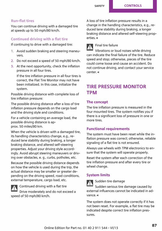
Run-flat tiresYou can continue driving with a damaged tireat speeds up to 50 mph/80 km/h.
Continued driving with a flat tireIf continuing to drive with a damaged tire:
1. Avoid sudden braking and steering maneu‐vers.
2. Do not exceed a speed of 50 mph/80 km/h.3. At the next opportunity, check the inflation
pressure in all four tires.If the tire inflation pressure in all four tires iscorrect, the Flat Tire Monitor may not havebeen initialized. In this case, initialize thesystem.
Possible driving distance with complete loss oftire inflation pressure:The possible driving distance after a loss of tireinflation pressure depends on the cargo loadand the driving style and conditions.For a vehicle containing an average load, thepossible driving distance is ap‐prox. 50 miles/80 km.When the vehicle is driven with a damaged tire,its handling characteristics change, e.g., re‐duced lane stability during braking, a longerbraking distance, and altered self-steeringproperties. Adjust your driving style accord‐ingly. Avoid abrupt steering maneuvers or driv‐ing over obstacles, e. g., curbs, potholes, etc.Because the possible driving distance dependson how the vehicle is used during the trip, theactual distance may be smaller or greater de‐pending on the driving speed, road conditions,external temperature, cargo load, etc.
Continued driving with a flat tireDrive moderately and do not exceed a
speed of 50 mph/80 km/h.
A loss of tire inflation pressure results in achange in the handling characteristics, e.g., re‐duced lane stability during braking, a longerbraking distance and altered self-steering prop‐erties.◀
Final tire failureVibrations or loud noises while driving
can indicate the final failure of the tire. Reducespeed and stop; otherwise, pieces of the tirecould come loose and cause an accident. Donot continue driving, and contact your servicecenter.◀
Tire Pressure MonitorTPMThe conceptThe tire inflation pressure is measured in thefour mounted tires. The system notifies you ifthere is a significant loss of pressure in one ormore tires.
Functional requirementsThe system must have been reset while the in‐flation pressure was correct; otherwise, reliablesignaling of a flat tire is not ensured.Always use wheels with TPM electronics to en‐sure that the system will operate properly.Reset the system after each correction of thetire inflation pressure and after every tire orwheel change.
System limitsSudden tire damageSudden serious tire damage caused by
external influences cannot be indicated in ad‐vance.◀
The system does not operate correctly if it hasnot been reset. For example, a flat tire may beindicated despite correct tire inflation pres‐sures.
Seite 87
Safety Controls
87Online Edition for Part no. 01 40 2 911 544 - VI/13

The system is inactive and cannot indicate a flattire:▷ For a mounted wheel without TPM elec‐
tronics.▷ When the TPM is disturbed by other sys‐
tems or devices with the same radio fre‐quency.
Status display1. "Vehicle Info"2. "Vehicle status"3. "Tire Pressure Monitor - TPM"
The status is displayed.
Status indicator on the Control DisplayThe tire and system status is indicated by thecolor of the tires.A change in the tire inflation pressure duringdriving is taken into account.A correction is only necessary if this is indicatedby the TPM
Wheels, greenThe tire inflation pressure is equal to the targetstate."TPM active" is displayed on the onboard moni‐tor.
One wheel is yellowA flat tire or major drop in inflation pressure inthe indicated tire.
All wheels are yellow▷ A flat tire or major drop in inflation pressure
in several tires.▷ The system was not reset after a wheel
change and thus issues a warning based onthe inflation pressures initialized last.
▷ A flat tire in one or more tires while the sys‐tem is being reset.
Wheels, grayThe system cannot detect a flat tire.Reasons for this may be:▷ TPM is being reset.▷ Disturbance by systems or devices with the
same radio frequency.▷ Malfunction.
Resetting the systemReset the system after each correction of thetire inflation pressure and after every tire orwheel change.
1. "Vehicle Info"2. "Vehicle status"3. "Reset"
4. Start the engine - do not drive away.5. Start the initialization with "Reset".6. Drive away.The tires are shown in gray and "ResettingTPM..." is displayed.After driving a few minutes, the set inflationpressures in the tires are accepted as the targetvalues to be monitored. The resetting process is
Seite 88
Controls Safety
88 Online Edition for Part no. 01 40 2 911 544 - VI/13

completed automatically as you drive. On theControl Display, the tires are shown in greenand "Status: TPM active" is displayed again.The trip can be interrupted at any time. If youdrive away again, the process resumes auto‐matically.If a flat tire is detected while the system is re‐setting, all tires on the Control Display are dis‐played in yellow. The message "Low tire!" isshown.
Low tire pressure messageThe warning lamps come on in yellowand red. A message is displayed on theonboard monitor. In addition, a signalsounds.
▷ There is a flat tire or substantial loss of infla‐tion pressure on the indicated wheel.
▷ The system was not reset after a wheelchange and thus issues warnings based onthe inflation pressures initialized last.
1. Reduce your speed and stop cautiously.Avoid sudden braking and steering maneu‐vers.
2. Check whether the vehicle is fitted withregular tires or run-flat tires.Run-flat tires, refer to page 228, are la‐beled with a circular symbol containing theletters RSC marked on the tire sidewall.
Do not continue driving without run-flattires
Do not continue driving if the vehicle is notequipped with run-flat tires; continued drivingmay result in serious accidents.◀
When a low inflation pressure is indicated, DSCDynamic Stability Control is switched on if nec‐essary.
Actions in the event of a flat tire
Normal tires1. Identify the damaged tire.
Do this by checking the air pressure in allfour tires. The tire pressure gauge of theMobility System, refer to page 229, can beused for this purpose.If the tire inflation pressure in all four tires iscorrect, the Tire Pressure Monitor may nothave been reset. Reset the system.If an identification is not possible, pleasecontact the service center.
2. Rectify the flat tire using the Mobility Sys‐tem, refer to page 229.Use of tire sealant, e.g., the Mobility Sys‐tem, may damage the TPM wheel electron‐ics. In this case, have the electronicschecked at the next opportunity and havethem replaced if necessary.
Run-flat tiresYou can continue driving with a damaged tireat speeds up to 50 mph/80 km/h.
Do not continue driving without run-flattires
Do not continue driving if the vehicle is notequipped with run-flat tires; continued drivingmay result in serious accidents.◀
Continued driving with a flat tireIf continuing to drive with a damaged tire:
1. Avoid sudden braking and steering maneu‐vers.
2. Do not exceed a speed of 50 mph/80 km/h.3. Check the air pressure in all four tires at the
next opportunity.If the tire inflation pressure in all four tires iscorrect, the Tire Pressure Monitor may nothave been reset. Reset the system.
Possible driving distance with complete loss oftire inflation pressure:The possible driving distance after a loss of tireinflation pressure depends on the cargo loadand the driving style and conditions.
Seite 89
Safety Controls
89Online Edition for Part no. 01 40 2 911 544 - VI/13

For a vehicle containing an average load, thepossible driving distance is ap‐prox. 50 miles/80 km.When the vehicle is driven with a damaged tire,its handling characteristics change, e.g., re‐duced lane stability during braking, a longerbraking distance, and altered self-steeringproperties. Adjust your driving style accord‐ingly. Avoid abrupt steering maneuvers or driv‐ing over obstacles, e. g., curbs, potholes, etc.Because the possible driving distance dependson how the vehicle is used during the trip, theactual distance may be smaller or greater de‐pending on the driving speed, road conditions,external temperature, cargo load, etc.
Continued driving with a flat tireDrive moderately and do not exceed a
speed of 50 mph/80 km/h.A loss of tire inflation pressure results in achange in the handling characteristics, e.g., re‐duced lane stability during braking, a longerbraking distance and altered self-steering prop‐erties.◀
Final tire failureVibrations or loud noises while driving
can indicate the final failure of the tire. Reducespeed and stop; otherwise, pieces of the tirecould come loose and cause an accident. Donot continue driving, and contact your servicecenter.◀
Message when not resetThe yellow warning lamp lights up. Amessage is displayed on the onboardmonitor.
The system detected a wheel change but wasnot yet reset. Warnings regarding the currenttire inflation pressure are not reliable.Check the tire inflation pressure and reset thesystem, refer to page 88.
MalfunctionThe small warning lamp flashes in yel‐low and then lights up continuously; thelarger warning lamp comes on in yel‐low.
On the onboard monitor, the tires are shown ingray and a message appears.
No flat tire can be detected.Display in the following situations:▷ A wheel without TPM electronics is
mounted:Have the system checked by the servicecenter if necessary.
▷ Malfunction:Have the system checked.
▷ TPM could not be fully reset; reset the sys‐tem again.
The small warning lamp flashes in yel‐low and then lights up continuously; thelarger warning lamp comes on in yel‐low.
On the onboard monitor, the tires are shown ingray and a message appears.
No flat tire can be detected.Display in the following situation:▷ Disturbance by other systems or devices
with the same radio frequencyAfter leaving the area of the disturbance,the system automatically becomes activeagain.
Declaration according to NHTSA/FMVSS138 Tire Pressure Monitoring SystemsEach tire, including the spare (if provided)should be checked monthly when cold and in‐flated to the inflation pressure recommendedby the vehicle manufacturer on the vehicleplacard or tire inflation pressure label (If yourvehicle has tires of a different size than the sizeindicated on the vehicle placard or tire inflation
Seite 90
Controls Safety
90 Online Edition for Part no. 01 40 2 911 544 - VI/13

pressure label, you should determine theproper tire inflation pressure for those tires.).As an added safety feature, your vehicle hasbeen equipped with a tire pressure monitoringsystem (TPMS) that illuminates a low tire pres‐sure telltale when one or more of your tires issignificantly under-inflated. Accordingly, whenthe low tire pressure telltale illuminates, youshould stop and check your tires as soon aspossible, and inflate them to the proper pres‐sure. Driving on a significantly under-inflatedtire causes the tire to overheat and can lead totire failure. Under-inflation also reduces fuel ef‐ficiency and tire tread life, and may affect thevehicle's handling and stopping ability.Please note that the TPMS is not a substitute forproper tire maintenance, and it is the driver'sresponsibility to maintain correct tire pressure,even if under-inflation has not reached thelevel to trigger illumination of the TPMS low tirepressure telltale.Your vehicle has also been equipped with aTPMS malfunction indicator to indicate whenthe system is not operating properly. The TPMSmalfunction indicator is combined with the lowtire pressure telltale. When the system detectsa malfunction, the telltale will flash for approxi‐mately one minute and then remain continu‐ously illuminated. This sequence will continueupon subsequent vehicle startups as long asthe malfunction exists. When the malfunctionindicator is illuminated, the system may not beable to detect or signal low tire pressure as in‐tended. TPMS malfunctions may occur for a va‐riety of reasons, including the installation of re‐placement or alternate tires or wheels on thevehicle that prevent the TPMS from functioningproperly. Always check the TPMS malfunctiontelltale after replacing one or more tires orwheels on your vehicle to ensure that the re‐placement or alternate tires and wheels allowthe TPMS to continue to function properly.
Speed limitThe conceptEnter a speed for which a Check Control mes‐sage will be displayed when the speed isreached. This enables you to receive warnings ifyou exceed a speed limit in an urban area, forexample.You are only warned of reaching this speed asecond time if your vehicle speed falls below itagain by at least 3 mph/5 km/h.
Displaying, setting or changing thelimit1. "Settings"2. "Speed"3. "Warning at:"
4. Turn the MINI joystick to accept the setting.5. Press the MINI joystick to apply the setting.The limit is stored.
Applying your current speed as the limit1. "Settings"2. "Speed"
Seite 91
Safety Controls
91Online Edition for Part no. 01 40 2 911 544 - VI/13
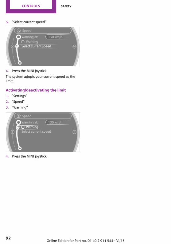
3. "Select current speed"
4. Press the MINI joystick.The system adopts your current speed as thelimit.
Activating/deactivating the limit1. "Settings"2. "Speed"3. "Warning"
4. Press the MINI joystick.
Seite 92
Controls Safety
92 Online Edition for Part no. 01 40 2 911 544 - VI/13

Driving stability control systemsVehicle equipmentThis chapter describes all series equipment aswell as country-specific and special equipmentoffered for this model series.Therefore, it alsodescribes equipment that may not be found inyour vehicle, for instance due to the selectedspecial equipment or the country version. Thisalso applies to safety-related functions and sys‐tems.
Antilock Brake SystemABSABS prevents locking of the wheels duringbraking.Steerability is maintained even during full brak‐ing. This increases active driving safety.ABS is operational every time you start the en‐gine.
Electronic brake-force distribution EBVThe system controls the brake pressure in therear wheels to ensure stable braking behavior.
CBC Cornering Brake ControlWhen braking in curves or during a lanechange, driving stability and steering responseare improved further.
Brake assistantWhen the brakes are applied rapidly, this sys‐tem automatically produces the maximumbraking force boost. In this way, the systemhelps keep the braking distance as short aspossible. This system utilizes all of the benefitsprovided by ABS.
Do not reduce the pressure on the brake pedalfor the duration of full braking.
Dynamic Stability Con‐trol DSCThe conceptDSC prevents traction loss in the driving wheelswhen driving away and accelerating.DSC also recognizes unstable vehicle condi‐tions, such as fishtailing or nose-diving. Subjectto physical limits, DSC helps to keep the vehicleon a steady course by reducing engine speedand by applying brakes to the individualwheels.DSC is operational every time you start the en‐gine.
Adjust your driving style to the situationAn appropriate driving style is always the
responsibility of the driver.The laws of physics cannot be repealed, evenwith DSC.Do not reduce the additional safety marginwith a risky driving style, as otherwise there is arisk of an accident.◀
Deactivating DSC
Press the switch until the DSC OFF indicatorlamp lights up in the speedometer and DSC OFF
Seite 93
Driving stability control systems Controls
93Online Edition for Part no. 01 40 2 911 544 - VI/13

appears in the tachometer. DSC is deactivated.Intervening measures to stabilize the vehicleand give it forward momentum are no longerexecuted.
When driving with snow chains or to rock thevehicle free of snow, it may be useful to deacti‐vate DSC temporarily.To increase vehicle stability, activate DSC againas soon as possible.
Activating DSCPress the switch again; the DSC indicator lampsin the display elements go out.
Indicator/warning lampsThe indicator lamp in the tachometerflashes: DSC is controlling the driveforces and brake forces.
The indicator lamp lights up: DSC and DTC hasfailed.
The indicator lamp in the speedometerlights up and DSC OFF appears in thetachometer.
DSC and DTC deactivated.
Dynamic Traction Con‐trol DTCThe conceptThe DTC system is a version of the DSC in whichforward momentum is optimized.
The system ensures maximum forward mo‐mentum on special road conditions, e.g., unp‐lowed snowy roads, but driving stability is lim‐ited.It is therefore necessary to drive with appropri‐ate caution.You may find it useful to briefly activate DTCunder the following special circumstances:▷ When driving in sand, on snowy inclines, in
slush, or on unplowed, snow-covered roadsurfaces
▷ When rocking a vehicle free or starting offin deep snow, sand, or on loose ground
▷ When driving with snow chains.
Activating DTC
Press the switch; the DSC OFF indicator lamplights up in the speedometer and TRACTIONappears in the tachometer. Dynamic StabilityControl DSC is deactivated, Dynamic TractionControl DTC is activated.
Deactivating DTCPress the switch again; the DSC OFF indicatorlamp in the speedometer and TRACTION in thetachometer go out.
Indicator/warning lampsThe indicator lamp in the tachometerflashes: DTC is controlling the driveforces and brake forces.
The indicator lamp lights up: DSC and DTC hasfailed.
Seite 94
Controls Driving stability control systems
94 Online Edition for Part no. 01 40 2 911 544 - VI/13

The indicator lamp in the speedometerlights up and TRACTION appears in thetachometer.
DTC is activated.
Hill drive-off assistantThis system supports driving away on gradients.The handbrake is not required.
1. Hold the vehicle in place with the footbrake.
2. Release the foot brake and drive awaywithout delay.
Driving off without delayAfter releasing the foot brake, start driv‐
ing without delay, since the drive-off assistantwill not hold the vehicle in place for more thanapprox. 2 seconds and the vehicle will beginrolling back.◀
ALL4 all-wheel systemALL4 is the all-wheel system of your MINI. Thecombined effects of ALL4 and DSC further opti‐mize the traction and dynamic driving charac‐teristics. The ALL4 all-wheel system variablydistributes the drive forces to the front and rearaxles depending on the driving situation andprevailing road conditions.
Sport buttonWhen this button is pressed, the vehicle re‐sponds in an even sportier manner.▷ The engine responds more spontaneously
to accelerator movements.▷ The steering responds more directly.▷ Cooper S, John Cooper Works: the engine
sounds sportier when coasting.▷ For automatic transmissions: more rapid
gear changes in the Sport program.
Activating the system
Press the switch; the LED in the button lights upand SPORT is displayed briefly in the tachome‐ter.
Deactivating the system▷ Press the switch again.▷ Switch the engine off.
Seite 95
Driving stability control systems Controls
95Online Edition for Part no. 01 40 2 911 544 - VI/13

Driving comfortVehicle equipmentThis chapter describes all series equipment aswell as country-specific and special equipmentoffered for this model series.Therefore, it alsodescribes equipment that may not be found inyour vehicle, for instance due to the selectedspecial equipment or the country version. Thisalso applies to safety-related functions and sys‐tems.
Cruise controlThe conceptThe system is functional at speeds beginning atapprox. 20 mph/30 km/h.The vehicle stores and maintains the speedspecified using the controls on the steeringwheel.
Do not use cruise controlDo not use the system if unfavorable con‐
ditions make it impossible to drive at a constantspeed, for instance:▷ On curvy roads.▷ In heavy traffic.▷ On slippery roads, in fog, snow or rain, or
on a loose road surface.Otherwise, you could lose control of the vehicleand cause an accident.◀
Controls
At a glance
1 Maintaining, storing, and increasing thespeed
2 Activating/deactivating cruise control3 Maintaining, storing, and reducing the
speed4 Resuming cruise control
Switching onPress button 2.
The indicator lamp lights up in thespeedometer. Cruise control is ready tooperate and can be activated.
Switching offPress button 2.▷ When activated: press twice.▷ When interrupted: press once.The displays go out. The stored target speed iscleared.
InterruptingPress button 2.The system is interrupted automatically if▷ The brakes are applied.▷ The clutch pedal is depressed.
Seite 96
Controls Driving comfort
96 Online Edition for Part no. 01 40 2 911 544 - VI/13

▷ The transmission position D is disengaged.▷ DSC intervenes.
Maintaining, storing the current speedPress button 1 or button 3.The current speed is maintained and stored. Itis displayed briefly in the tachometer.On downhill gradients, it may prove impossibleto maintain the set speed if the engine brakingpower is insufficient. On uphill gradients, it mayprove impossible to maintain the set speed ifthe engine power output is insufficient.
Increasing speed▷ Press button 1 repeatedly until the desired
speed is reached.Each time the button is pressed, the speedincreases by approx. 1 mph/1 km/h.
▷ Press and hold button 1 until the desiredspeed is reached.The vehicle accelerates without pressure onthe accelerator pedal. After the button isreleased, the achieved speed is maintainedand stored.
Decreasing speedPress button 3 repeatedly or hold it until thedesired speed is reached.The functions are the same those when thespeed is increased, only that the speed is re‐duced.
Resuming a speed stored beforehandPress button 4.The last stored speed is resumed and main‐tained.The stored speed is cleared when the ignition isswitched off.
Display in the tachometer
The selected speed is displayed briefly.
If the display --- mph or --- km/h appearsbriefly, conditions may not be adequate to op‐erate the system.
For better controlThe indicator lamp lights up in thespeedometer. Cruise control is ready tooperate and can be activated.
MalfunctionThe warning lamp in the tachometerlights up. A message appears on theControl Display. The system is malfunc‐
tioning or has failed.
Park Distance ControlPDCThe conceptPDC provides support when parking in reverse.Signal tones and a visual display indicate thatthe vehicle is approaching an object behind it.Measurements are made by four ultrasoundsensors in the bumpers.The range of these sensors is approx. 6 ft/2 m.An acoustic warning is first given:▷ By the two corner sensors at ap‐
prox. 24 in/60 cm.
Seite 97
Driving comfort Controls
97Online Edition for Part no. 01 40 2 911 544 - VI/13
▷ By the rear middle sensors at approx.5 ft/1.50 m.
Avoid driving quickly with PDCPDC is a parking aid that can display ob‐
jects when the vehicle approaches them slowly,as is the case during parking maneuvers. Avoiddriving toward an object quickly as the systemmay then be too late in issuing a warning fortechnical reasons.◀
Automatic operationThe system is activated after approx. one sec‐ond when reverse gear or selector lever posi‐tion R is engaged while the engine is running orthe ignition is switched on. Await this short pe‐riod before setting the vehicle into motion.
Signal tonesThe closer the vehicle is to the object, theshorter the intervals become. If the distance toa detected object is less than approx.12 in/30 cm, a continuous tone is sounded.If the distance remains constant, for examplewhen driving parallel to a wall, the signal toneis stopped after approx. 3 seconds.
PDC with visual warningDisplaying the approach to an object on theControl Display. The contours of distant objectsare displayed on the Control Display before asignal tone is output. The display is shown onthe Control Display as soon as reverse gear orselector lever position R is engaged.
System limitsCheck the traffic situation as wellPDC cannot serve as a substitute for the
driver's personal judgment of the traffic situa‐tion. Check the traffic situation around the ve‐hicle with your own eyes. Otherwise, an acci‐dent could result from road users or objectslocated outside of the PDC detection range.
Loud noises from outside and inside the vehiclemay prevent you from hearing the PDC's signaltone.◀
MalfunctionThe warning lamp lights up. A messageappears on the Control Display. PDC ismalfunctioning or has failed. Have the
system checked.
To ensure full functionality of the sensors, keepthe sensors clean and free of ice. When usinghigh-pressure washers, do not spray the sen‐sors for long periods and maintain a distance ofat least 12 in/30 cm.
Seite 98
Controls Driving comfort
98 Online Edition for Part no. 01 40 2 911 544 - VI/13

ClimateVehicle equipmentThis chapter describes all series equipment aswell as country-specific and special equipmentoffered for this model series.Therefore, it also
describes equipment that may not be found inyour vehicle, for instance due to the selectedspecial equipment or the country version. Thisalso applies to safety-related functions and sys‐tems.
Air conditioning
1 Air volume2 Cooling function3 Recirculated air mode4 Temperature
5 Rear window defroster6 Vent settings7 Windshield heating
Air volumeVary the air volume. The higherthe rate, the more effective theheating or cooling will be.The air flow rate may be reducedor the blower may be switched
off entirely to save on battery power.
Switching the system on/offTurn the rotary switch for the air volume to 0.The blower and air conditioner are completelyswitched off and the air supply is cut off.Set any air volume to switch on the air condi‐tioning.
Seite 99
Climate Controls
99Online Edition for Part no. 01 40 2 911 544 - VI/13
Cooling functionThe passenger compartment canonly be cooled with the enginerunning.The cooling function cools anddehumidifies the incoming air
before reheating it as required, according tothe temperature setting.The cooling function helps to prevent conden‐sation on the windows or to remove it quickly.
Depending on the weather, the windshield mayfog up briefly when the engine is started.To cool the air faster and more intensivelywhen external temperatures are high, switchon the recirculated air mode.
Recirculated air modeIf the air outside the car has anunpleasant odor or contains pol‐lutants, shut off the supply to theinterior of the car temporarily.The system then recirculates the
air currently within the vehicle.
Should the windows fog up in the recirculated-air mode, press the AUTO button or switch offthe recirculated-air mode and increase the airvolume if necessary. Make sure that air canflow onto the windshield.Recirculated air mode is automatically deacti‐vated at low external temperatures.
Only use recirculated air mode for a lim‐ited period
The recirculated air mode should not be usedcontinuously for lengthy periods; otherwise, thequality of the air inside the car will graduallydeteriorate.◀
TemperatureTurn upward, red, to raise thetemperature.Turn downward, blue, to lowerthe temperature.
Rear window defrosterThe rear window defrosterswitches off automatically after acertain period of time.The rear window defrosterpower may be lowered or even
switched off entirely to save on battery power.
Vent settingsDirect the flow of air to the win‐dows , to the upper bodyarea , or to the footwell .Intermediate positions are possi‐ble.
Windshield heatingThe windshield heating switchesoff automatically after sometime.The windshield heating may bereduced or even switched off en‐
tirely to save on battery power.
Defrosting and defogging windows1. Set the maximum air volume.2. Air distribution in position .
By switching on the cooling function, thewindows are defogged more rapidly.
3. Set the highest temperature, red.4. Deactivate recirculated air mode.5. Switch on the windshield heating if neces‐
sary.6. Switch on the rear window defroster if nec‐
essary.
Seite 100
Controls Climate
100 Online Edition for Part no. 01 40 2 911 544 - VI/13

MicrofilterThe microfilter traps dust and pollen. The mi‐crofilter is changed by the service center duringroutine maintenance work.
Microfilter/activated-charcoal filterThe microfilter traps dust and pollen. The acti‐vated-charcoal filter provides additional protec‐
tion by filtering gaseous pollutants from theoutside air. The service center replaces thiscombined filter during routine maintenance.
Automatic climate control
1 Air volume, manual2 AUTO program3 Recirculated air mode4 Maximum cooling5 Manual air distribution6 Temperature
7 Defrosting windows and removing conden‐sation
8 Cooling function9 Rear window defroster10 Windshield heating
Comfortable interior climateThe AUTO program offers the optimum air dis‐tribution and air volume for virtually all condi‐tions, refer to AUTO program below. Select acomfortable interior temperature only.
The following sections contain more detailedinformation on the available setting options.Most of these settings are stored for the remotecontrol in use, Personal Profile settings, refer topage 33.
Seite 101
Climate Controls
101Online Edition for Part no. 01 40 2 911 544 - VI/13
Air volume, manualPress the – button to reduce theair volume. Press the + button toincrease the air volume.The automatic mode for the airvolume can be switched on
again using the AUTO button.
The air flow rate may be reduced or the blowermay be switched off entirely to save on batterypower. The display remains the same.
Switching the system on/offReduce the air volume by pressing the – buttonuntil the system is switched off. All displays goout.Press the AUTO button to switch the automaticclimate control back on.
AUTO programThe AUTO program automati‐cally adjusts the air distributionto the windshield and side win‐dows, toward the upper bodyarea, and into the footwell. The
air volume and your specifications for the tem‐perature are adjusted to outside influences dueto the seasons, e. g., solar radiation.The cooling function is switched on automati‐cally with the AUTO program.The program is switched off if the air distribu‐tion is manually adjusted or the button ispressed again.
Recirculated air modeIf the air outside the car has anunpleasant odor or contains pol‐lutants, shut off the supply to theinterior of the car temporarily.The system then recirculates the
air currently within the vehicle.
Should the windows fog up in the recirculated-air mode, press the AUTO button or switch off
the recirculated-air mode and increase the airvolume if necessary. Make sure that air canflow onto the windshield.Recirculated air mode is automatically deacti‐vated at low external temperatures.
Only use recirculated air mode for a lim‐ited period
The recirculated air mode should not be usedcontinuously for lengthy periods; otherwise, thequality of the air inside the car will graduallydeteriorate.◀
Maximum coolingAutomatic climate controlswitches to the lowest tempera‐ture, a high air volume, and re‐circulated air mode.For maximum cooling, open the
vents for the upper body area.
The air is cooled as quickly as possible:▷ At an external temperature above
32 ℉/0 ℃.▷ When the engine is running.
Manual air distributionThe flow of air is directed, as se‐lected, to the windows, to theupper body area, or to the foot‐well.The automatic mode for the air
distribution can be switched back on using theAUTO button.
TemperatureSet the desired temperature in‐dividually.The automatic climate controlachieves this temperature asquickly as possible regardless of
the season, using maximum cooling or heatingpower if necessary, and then maintains it.
Seite 102
Controls Climate
102 Online Edition for Part no. 01 40 2 911 544 - VI/13

When switching between different temperaturesettings in rapid succession, the automatic cli‐mate control does not have sufficient time toadjust the set temperature.
Rear window defrosterThe rear window defrosterswitches off automatically after acertain period of time.
Depending on the vehicle equipment, upperwires are used as an antenna and are not partof the rear window defroster.
Defrosting and defogging windowsQuickly removes ice and con‐densation from the windshieldand front side windows. For thispurpose, also switch on the cool‐ing function.
The windshield heating switches on automati‐cally.
Windshield heatingThe windshield heating switchesoff automatically after sometime.
Cooling functionThe cooling function cools anddehumidifies the incoming airbefore reheating it as required,according to the temperaturesetting. The passenger compart‐
ment can only be cooled with the engine run‐ning.
The cooling function helps to prevent conden‐sation on the windows or to remove it quickly.
Depending on the weather, the windshield mayfog up briefly when the engine is started. Recir‐culated air mode is switched on automatically ifnecessary.The cooling function is switched on automati‐cally when the AUTO button is pressed.
Microfilter/activated-charcoal filterThe microfilter traps dust and pollen. The acti‐vated-charcoal filter provides additional protec‐tion by filtering gaseous pollutants from theoutside air. The service center replaces thiscombined filter during routine maintenance.
Ventilation
1 Knob for continuous opening and closing2 Nozzle for direction of air flow
Opening/closingTurn the knob.
Direction of air flowPivot the entire nozzle.
Seite 103
Climate Controls
103Online Edition for Part no. 01 40 2 911 544 - VI/13
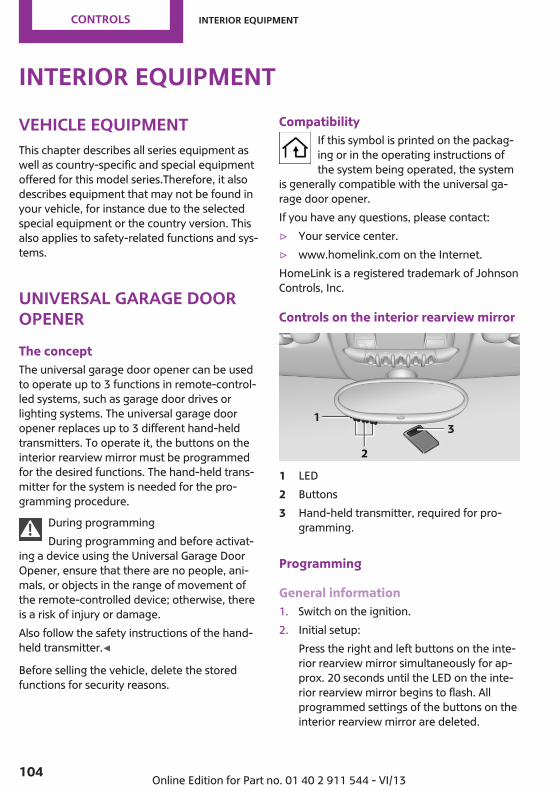
Interior equipmentVehicle equipmentThis chapter describes all series equipment aswell as country-specific and special equipmentoffered for this model series.Therefore, it alsodescribes equipment that may not be found inyour vehicle, for instance due to the selectedspecial equipment or the country version. Thisalso applies to safety-related functions and sys‐tems.
Universal garage dooropenerThe conceptThe universal garage door opener can be usedto operate up to 3 functions in remote-control‐led systems, such as garage door drives orlighting systems. The universal garage dooropener replaces up to 3 different hand-heldtransmitters. To operate it, the buttons on theinterior rearview mirror must be programmedfor the desired functions. The hand-held trans‐mitter for the system is needed for the pro‐gramming procedure.
During programmingDuring programming and before activat‐
ing a device using the Universal Garage DoorOpener, ensure that there are no people, ani‐mals, or objects in the range of movement ofthe remote-controlled device; otherwise, thereis a risk of injury or damage.Also follow the safety instructions of the hand-held transmitter.◀
Before selling the vehicle, delete the storedfunctions for security reasons.
CompatibilityIf this symbol is printed on the packag‐ing or in the operating instructions ofthe system being operated, the system
is generally compatible with the universal ga‐rage door opener.If you have any questions, please contact:▷ Your service center.▷ www.homelink.com on the Internet.HomeLink is a registered trademark of JohnsonControls, Inc.
Controls on the interior rearview mirror
1 LED2 Buttons3 Hand-held transmitter, required for pro‐
gramming.
Programming
General information1. Switch on the ignition.2. Initial setup:
Press the right and left buttons on the inte‐rior rearview mirror simultaneously for ap‐prox. 20 seconds until the LED on the inte‐rior rearview mirror begins to flash. Allprogrammed settings of the buttons on theinterior rearview mirror are deleted.
Seite 104
Controls Interior equipment
104 Online Edition for Part no. 01 40 2 911 544 - VI/13

3. Hold the hand-held transmitter of the sys‐tem to be operated a distance of approx. 1to 3 in/2.5 to 8 cm away from the buttonson the interior rearview mirror. The re‐quired distance depends on the particularhand-held transmitter.
4. Press the button of the desired function onthe hand-held transmitter and the buttonbeing programmed on the interior rearviewmirror simultaneously and hold. The LED onthe interior rearview mirror flashes slowly atfirst.
5. When the LED flashes more rapidly, releaseboth buttons. Rapid flashing indicates thatthe button on the interior rearview mirrorhas been programmed.If the LED does not flash faster after 60 sec‐onds, change the distance between the in‐terior rearview mirror and the hand-heldtransmitter and repeat the step. Multipletrials at different distances may be neces‐sary. Wait at least 15 seconds between tri‐als.
6. To program additional functions on otherbuttons, repeat steps 3 to 5.
The systems can be operated with the buttonson the interior rearview mirror.
Special characteristics of alternating-code radio systemsIf the system cannot be operated after re‐peated programming, check whether the sys‐tem to be operated uses an alternating-codesystem.Read the operating instructions of the systemor press and hold the programmed button onthe interior rearview mirror. If the LED on theinterior rearview mirror flashes rapidly at firstand then lights up continuously for 2 seconds,the system is equipped with an alternating-code system. This flashing LED pattern repeatsitself for approx. 20 seconds.
In systems with an alternating-code system, theuniversal garage door opener and the systemmust be additionally synchronized.Please obtain additional information on syn‐chronization in the operating instructions of thesystem being set up.The systems will be easier to synchronize withthe aid of a second person.Synchronization:
1. Park the vehicle within range of the re‐mote-controlled system.
2. Program the corresponding button on theinterior rearview mirror as described.
3. Identify and press the synchronization but‐ton on the system being set up. You haveapprox. 30 seconds for the next step.
4. Press and hold the button on the interiorrearview mirror for approx. 3 seconds andthen release it. Repeat this step up to threetimes if necessary to complete the synchro‐nization procedure. When synchronizationis completed, the programmed function isexecuted.
Reprogramming individual buttons1. Switch on the ignition.2. Hold the hand-held transmitter at a dis‐
tance of approx. 1 to 3 in/2.5 to 8 cm fromthe memory buttons.The required distance depends on the par‐ticular hand-held transmitter.
3. Press the memory button of the universalgarage door opener.
4. If the LED flashes slowly after approx.20 seconds, press the transmit button onthe hand-held transmitter.
5. Release both buttons when the LED flashesrapidly.If the LED does not flash rapidly after ap‐prox. 60 seconds, change the distance andrepeat the step.
Seite 105
Interior equipment Controls
105Online Edition for Part no. 01 40 2 911 544 - VI/13

Canada: if the LED does not flash rapidly af‐ter approx. 60 seconds, change the dis‐tance and repeat the step. If programmingwas aborted by the hand-held transmitter,hold down the memory button and pressand release the button on the hand-heldtransmitter several times for 2 seconds.
ControlsPrior to operationBefore operating a unit with the Universal
Garage Door Opener, ensure that there are nopeople, animals, or objects in the range ofmovement of the system; otherwise, there is arisk of injury or damage.Also follow the safety instructions of the hand-held transmitter.◀
The system, such as the garage door, can beoperated using the button on the interior rear‐view mirror with the engine running or the igni‐tion switched on. When you are within the re‐ception range of the system, press and hold thebutton until the function is initiated. The LED onthe interior rearview mirror lights up continu‐ously while the radio signal is being transmit‐ted.
Deleting stored functionsPress the right and left buttons on the interiorrearview mirror simultaneously for approx.20 seconds until the LED flashes rapidly. Allstored functions are deleted. The functions can‐not be deleted individually.
Digital compass
1 Adjustment button on the back of the mir‐ror
2 Display
The display shows the main or secondary com‐pass direction in which the vehicle is traveling.
Operating conceptVarious functions can be called up by pressingthe adjustment button with a pointed objectsuch as a pen. The following adjustment op‐tions are displayed one after the other, de‐pending on how long the adjustment button ispressed:▷ Press briefly: switch the display on/off.▷ 3 to 6 seconds: set the compass zone.▷ 6 to 9 seconds: calibrate the compass.▷ 9 to 12 seconds: set left-hand/right hand
steering.▷ 12 to 15 seconds: set the language.
Setting compass zonesSet the compass zone corresponding to the ve‐hicle's geographic location so that the compasscan function correctly; refer to the world mapwith compass zones.
Seite 106
Controls Interior equipment
106 Online Edition for Part no. 01 40 2 911 544 - VI/13

Press the adjustment button for 3‑4 seconds.The number of the compass zone set is shownin the display.To change the zone setting, briefly press theadjustment button repeatedly until the displayshows the number of the compass zone corre‐sponding to the current location.The compass is operational again after approx.10 seconds.
Calibrating the digital compassThe digital compass must be calibrated in thefollowing situations:▷ An incorrect compass direction is shown.▷ The cardinal direction displayed does not
change even if the direction of travelchanges.
▷ Not all compass directions are shown.
Procedure1. Make sure that there are no large metal ob‐
jects or overhead power lines in the vicinityof the vehicle and that there is enoughspace to drive in a circle.
2. Set the currently valid compass zone.3. Press the adjustment button for 6‑7 sec‐
onds to call up C. Then drive at least one fullcircle at a maximum speed of4 mph/7 km/h. When the system is cali‐brated, the C is replaced by the compass di‐rections.
Right-hand/left-hand steeringThe digital compass is set for right-hand or left-hand steering at the factory.
Setting the languagePress the adjustment button for 12‑13 seconds.Briefly press the adjustment button again toswitch between English "E" and German "O".The setting is automatically saved after approx.10 seconds.
Seite 107
Interior equipment Controls
107Online Edition for Part no. 01 40 2 911 544 - VI/13

Cupholders and ashtray/lighter
CupholdersTwo cupholders are located in the center con‐sole in the front.MINI Countryman: two additional cupholdersare located at the end of the center console inthe rear. Additional cupholders can be installedon the center rail.
MINI Paceman: additional cupholders are lo‐cated in the console between the rear seats.
Depending on the equipment, additional cu‐pholders can be installed on the center rail.
Shatter-proof containers and no hotdrinks
Use light and shatter-proof containers and donot transport hot drinks. Otherwise, there is theincreased danger of injury in an accident.◀
Unsuitable containersDo not forcefully push unsuitable contain‐
ers into the cupholders. This may result in dam‐age.◀
AshtrayThe ashtray is located in one of the cupholdersin the center console at the front.
EmptyingTake out the entire ashtray, arrow.When installing, ensure that the ashtray is in‐serted in the cupholder with the adapter.
Lighter
With the engine running or the ignitionswitched on, press in the cigarette lighter.The lighter can be removed as soon as it popsback out.
Danger of burnsOnly hold the hot lighter by its head; oth‐
erwise, there is the danger of getting burned.Switch off the ignition and take the remotecontrol with you when leaving the vehicle sothat children cannot use the lighter and burnthemselves.◀
Seite 108
Controls Interior equipment
108 Online Edition for Part no. 01 40 2 911 544 - VI/13
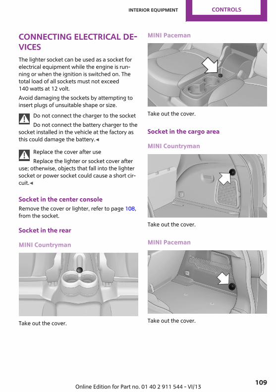
Connecting electrical de‐vicesThe lighter socket can be used as a socket forelectrical equipment while the engine is run‐ning or when the ignition is switched on. Thetotal load of all sockets must not exceed140 watts at 12 volt.Avoid damaging the sockets by attempting toinsert plugs of unsuitable shape or size.
Do not connect the charger to the socketDo not connect the battery charger to the
socket installed in the vehicle at the factory asthis could damage the battery.◀
Replace the cover after useReplace the lighter or socket cover after
use; otherwise, objects that fall into the lightersocket or power socket could cause a short cir‐cuit.◀
Socket in the center consoleRemove the cover or lighter, refer to page 108,from the socket.
Socket in the rear
MINI Countryman
Take out the cover.
MINI Paceman
Take out the cover.
Socket in the cargo area
MINI Countryman
Take out the cover.
MINI Paceman
Take out the cover.
Seite 109
Interior equipment Controls
109Online Edition for Part no. 01 40 2 911 544 - VI/13

Cargo areaCargo cover
Do not place objects on the coversDo not place objects on the cover; if you
do so, they may pose a danger to vehicle occu‐pants during braking or evasive maneuvers ordamage the cover.◀
When the tailgate is opened, the cargo cover israised.To load bulky luggage, the cover can be re‐moved.
1. Detach the securing straps from the tail‐gate.
2. Lift the cover slightly, arrow 1, and pull itback and out of the bracket, arrow 2.
MINI Countryman:
MINI Paceman:
MINI Countryman: rear seat backrestsDanger of pinchingBefore folding down the rear seat back‐
rests, ensure that path of movement of thebackrests is clear. Especially when the middlesection is folded down, ensure that no one islocated in or reaches into the path of move‐ment of the rear seat backrests. Otherwise, in‐juries or damage may result.◀
Observe the instructions concerning thesafety belt
Observe the instructions concerning the safetybelt, refer to page 47. Otherwise, personal pro‐tection may be compromised.◀
The rear seat backrest is divided at a ratio of40-20-40.When the outer rear seat backrests are foldeddown, it is not permissible for a person to travelon the center seat.Remove the third head restraint, refer topage 50, if necessary.Open the center safety belt and insert it in thebelt holder on the headliner, refer to page 48.Enlarge the cargo area by adjusting the rearseat backrests to a more upright position.The backrests can be adjusted to 10 differentpositions between the comfort and transportpositions and they can be folded down.In the comfort position, the backrests are tiltedback to the greatest possible angle and in thetransport position they are nearly vertical.
Seite 110
Controls Interior equipment
110 Online Edition for Part no. 01 40 2 911 544 - VI/13

Before beginning with the mounting of a childrestraint fixing system, note the instructions,refer to page 53.
1. Hold the top of the backrest, for examplethe head restraint, and pull on the loop, ar‐row.
2. Engage the backrest in the desired positionor fold it down.
Folding the backrests back upLocking the backrestWhen folding back, ensure that the locks
engage properly; otherwise, cargo could becatapulted forward into the passenger com‐partment during braking maneuvers andswerving, endangering the occupants.◀
No child restraint fixing systemsDo not mount child restraint fixing sys‐
tems in the rear when the rear seat backrestsare adjusted to a more vertical position; other‐wise, the protection provided by these systemsmay be reduced.◀
When the backrests are folded back up, theyengage in the transport position.To set the desired backrest inclination or com‐fort position, hold the backrest, pull the loopforward, and adjust the backrest.
MINI Paceman: rear seat backrestsDanger of pinchingBefore folding down the rear seat back‐
rests, ensure that path of movement of thebackrests is clear; otherwise, injuries or damagemay result.◀
1. Pull on the respective loop, arrow.The backrest is unlocked.
2. Fold the backrest forward.
Folding the backrests back upHold the top of the backrest, for example thehead restraint, and fold it back.
Locking the backrestWhen folding back, ensure that the locks
engage properly; otherwise, cargo could becatapulted forward into the passenger com‐partment during braking maneuvers andswerving, endangering the occupants.◀
Flat loading floorMaximum loadDo not exceed the maximum load of
330 lbs, 150 kg, on the loading floor; otherwise,damage may result.◀
Access to storage areaA storage area for items like the partition net isfound under the loading floor.
1. Reach into the recess, arrow 1, on the rearedge of the loading floor.
Seite 111
Interior equipment Controls
111Online Edition for Part no. 01 40 2 911 544 - VI/13

2. Lift the loading floor at the rear, arrow 1,and fold it forward, arrow 2.
MINI Countryman:
MINI Paceman:
Before closing the tailgate, lower the loadingfloor back onto the cargo area floor.
RemovingThe loading floor can be removed if necessary.
1. Fold up the loading floor.2. Pull it back slightly and out of the holders.3. Then remove it upward.The folded loading floor can be stored in thecargo area.
MINI Countryman: partition netFirmly attach the partition netMake sure that the partition net is firmly
attached; otherwise, injuries may result.◀
Before installing1. Remove the pouch with the partition net
from the storage compartment under theloading floor in the cargo area.
2. Take the partition net out of the pouch, un‐roll it, and unfold it.After use, fold and roll up the partition netin the same manner and place it in thepouch so that it can be stowed back underthe cargo floor panel. Ensure that hooksand tensioning buckles do not rest on therod elements.
3. Unfold the partition net to the point wherethe rod elements engage.
Installation behind the front seats
1. Take out the cargo cover if necessary.2. Fold down the rear seat backrests, refer to
Enlarging the cargo area.3. Insert the retaining pins of the partition net
all the way into the front holders in theheadliner, arrow 1, and push forward.
4. Attach the hooks, arrow 2, at the bottom ofthe retaining straps on both sides to theeyelets on the vehicle floor.
5. Lash the partition net tightly. To do this,tighten the retaining straps using the ten‐sioning buckles.
RemovingTo remove and stow the partition net, proceedin reverse order.
Seite 112
Controls Interior equipment
112 Online Edition for Part no. 01 40 2 911 544 - VI/13

To fold up, press the release button, arrow.
MINI Countryman: multi-function hook
Hooks designed for hanging shopping bags andtotes, for example, are located on the left andright sides of the cargo cover support, arrow.
Do not hang heavy items from the hooksOnly hang light bags or suitable objects
from the holders. Otherwise, there is a dangerof objects flying about during braking and eva‐sive maneuvers.Only transport heavy luggage in the trunk if ithas been appropriately secured.◀
Seite 113
Interior equipment Controls
113Online Edition for Part no. 01 40 2 911 544 - VI/13
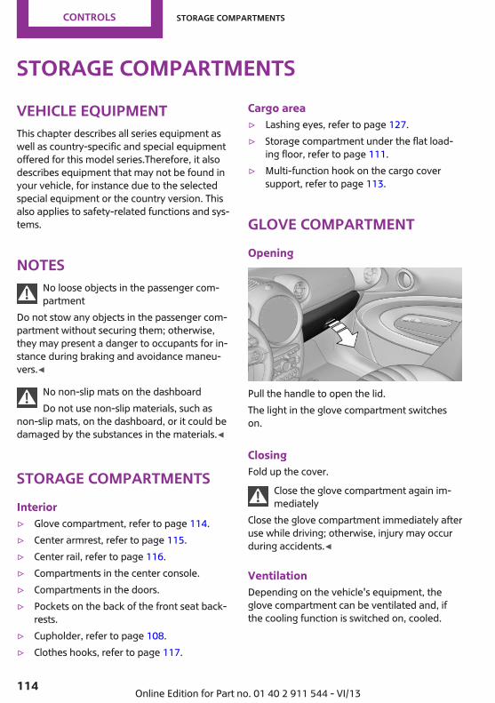
Storage compartmentsVehicle equipmentThis chapter describes all series equipment aswell as country-specific and special equipmentoffered for this model series.Therefore, it alsodescribes equipment that may not be found inyour vehicle, for instance due to the selectedspecial equipment or the country version. Thisalso applies to safety-related functions and sys‐tems.
NotesNo loose objects in the passenger com‐partment
Do not stow any objects in the passenger com‐partment without securing them; otherwise,they may present a danger to occupants for in‐stance during braking and avoidance maneu‐vers.◀
No non-slip mats on the dashboardDo not use non-slip materials, such as
non-slip mats, on the dashboard, or it could bedamaged by the substances in the materials.◀
Storage compartmentsInterior▷ Glove compartment, refer to page 114.▷ Center armrest, refer to page 115.▷ Center rail, refer to page 116.▷ Compartments in the center console.▷ Compartments in the doors.▷ Pockets on the back of the front seat back‐
rests.▷ Cupholder, refer to page 108.▷ Clothes hooks, refer to page 117.
Cargo area▷ Lashing eyes, refer to page 127.▷ Storage compartment under the flat load‐
ing floor, refer to page 111.▷ Multi-function hook on the cargo cover
support, refer to page 113.
Glove compartmentOpening
Pull the handle to open the lid.The light in the glove compartment switcheson.
ClosingFold up the cover.
Close the glove compartment again im‐mediately
Close the glove compartment immediately afteruse while driving; otherwise, injury may occurduring accidents.◀
VentilationDepending on the vehicle's equipment, theglove compartment can be ventilated and, ifthe cooling function is switched on, cooled.
Seite 114
Controls Storage compartments
114 Online Edition for Part no. 01 40 2 911 544 - VI/13

Opening
Turn the switch in the direction of the arrow.
ClosingMove the switch to the vertical position byturning it in the opposite direction of the arrow.Depending on the temperature setting of theair conditioning or automatic climate control,high temperatures may occur in the glove com‐partment.
USB interface for data transferUpdating the navigation data, refer topage 134, from the USB medium via the USBinterface in the glove compartment.Observe the following when connecting:▷ Do not use force when plugging the con‐
nector into the USB interface.▷ Do not connect devices such as fans or
lamps to the USB interface.▷ Do not connect USB hard drives.▷ Do not use the USB interface to recharge
external devices.
Center armrestThe center armrest between the front seatscontains a storage compartment or a cover forthe snap-in adapter, refer to page 200, de‐pending on the equipment.The center armrest between the rear seats con‐tains a storage compartment.
Do not position tall accessory parts directly onthe center rail of the center armrest; otherwise,they may be damaged when the center arm‐rest is opened or closed.
Center armrest front
OpeningPress the button, arrow, and pull up the lid.
MINI Paceman: center armrest, rear
RemovingThe rear center armrest can be removed to en‐large the loading area.
1. Turn the handwheel counterclockwise allthe way to open it, arrow 1.
2. Push the center armrest back slightly in thebase plate, arrow 2.
3. Lift the center armrest at the front andpivot it out.
Seite 115
Storage compartments Controls
115Online Edition for Part no. 01 40 2 911 544 - VI/13
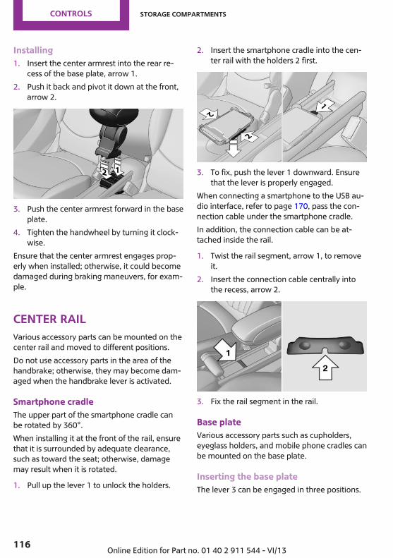
Installing1. Insert the center armrest into the rear re‐
cess of the base plate, arrow 1.2. Push it back and pivot it down at the front,
arrow 2.
3. Push the center armrest forward in the baseplate.
4. Tighten the handwheel by turning it clock‐wise.
Ensure that the center armrest engages prop‐erly when installed; otherwise, it could becomedamaged during braking maneuvers, for exam‐ple.
Center railVarious accessory parts can be mounted on thecenter rail and moved to different positions.Do not use accessory parts in the area of thehandbrake; otherwise, they may become dam‐aged when the handbrake lever is activated.
Smartphone cradleThe upper part of the smartphone cradle canbe rotated by 360°.When installing it at the front of the rail, ensurethat it is surrounded by adequate clearance,such as toward the seat; otherwise, damagemay result when it is rotated.
1. Pull up the lever 1 to unlock the holders.
2. Insert the smartphone cradle into the cen‐ter rail with the holders 2 first.
3. To fix, push the lever 1 downward. Ensurethat the lever is properly engaged.
When connecting a smartphone to the USB au‐dio interface, refer to page 170, pass the con‐nection cable under the smartphone cradle.In addition, the connection cable can be at‐tached inside the rail.
1. Twist the rail segment, arrow 1, to removeit.
2. Insert the connection cable centrally intothe recess, arrow 2.
3. Fix the rail segment in the rail.
Base plateVarious accessory parts such as cupholders,eyeglass holders, and mobile phone cradles canbe mounted on the base plate.
Inserting the base plateThe lever 3 can be engaged in three positions.
Seite 116
Controls Storage compartments
116 Online Edition for Part no. 01 40 2 911 544 - VI/13

0 Setting1 Adjusting the position on the rail2 Inserting the base plate
To insert, move the lever to position 2.
Adjusting the position and fixing1. Push lever 3 into position 1.2. Adjust the position of the base plate.3. Push lever 3 downward into position 0.
Do not apply excessive pressure to thelever.
The base plate is fixed.Fix the base plateFix the base plate before driving away;
otherwise, injuries may result during an acci‐dent.◀
An example: eyeglass holderAttach the eyeglass holder and adjust the posi‐tion.
Mounting the eyeglass holder1. If necessary, fix the base plate, refer to Ad‐
justing the position and fixing.2. Pull up lever 6 to unlock the holders.
3. First engage the eyeglass holder in thefront holders 4 and then in the rear hold‐ers 5.
Ensure that lever 6 is across from holder 4.
Clothes hooksClothes hooks are located on the grab handlesin the rear.
Do not obstruct viewWhen suspending clothing from the
hooks, ensure that it will not obstruct the driv‐er's vision.◀
No heavy objectsDo not hang heavy objects from the
hooks; otherwise, they may present a dangerto passengers during braking and evasive ma‐neuvers.◀
Seite 117
Storage compartments Controls
117Online Edition for Part no. 01 40 2 911 544 - VI/13
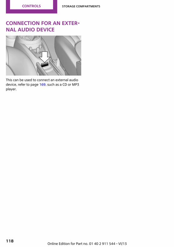
Connection for an exter‐nal audio device
This can be used to connect an external audiodevice, refer to page 169, such as a CD or MP3player.
Seite 118
Controls Storage compartments
118 Online Edition for Part no. 01 40 2 911 544 - VI/13

Seite 119
Storage compartments Controls
119Online Edition for Part no. 01 40 2 911 544 - VI/13

DRIVE ME.
Online Edition for Part no. 01 40 2 911 544 - VI/13

At a glance
Controls
Driving tips
Navigation
Entertainment
Communication
Mobility
Reference
Online Edition for Part no. 01 40 2 911 544 - VI/13
Things to remember when drivingVehicle equipmentThis chapter describes all series equipment aswell as country-specific and special equipmentoffered for this model series.Therefore, it alsodescribes equipment that may not be found inyour vehicle, for instance due to the selectedspecial equipment or the country version. Thisalso applies to safety-related functions and sys‐tems.
Breaking-in periodGeneral informationMoving parts need to be broken in to adjust toeach other.The following instructions will help achieve along vehicle life and good economy.
Engine and differentialAlways obey all official speed limits.
Up to 1,200 miles/2,000 kmDrive at various engine and vehicle speeds, butdo not exceed:▷ For a gasoline engine, 4,500 rpm and
100 mph/160 km/h.Avoid full-throttle operation and use of thetransmission's kickdown mode for the initialmiles.
From 1,200 miles/2,000 kmThe engine and vehicle speed can gradually beincreased.
TiresDue to technical factors associated with theirmanufacture, tires do not achieve their full trac‐
tion potential until after an initial breaking-inperiod.Drive conservatively for the first200 miles/300 km.
Brake systemBrakes require an initial break-in period of ap‐prox. 300 miles/500 km to achieve optimizedcontact and wear patterns between brake padsand discs. Drive cautiously during this break-inperiod.
ClutchThe clutch requires an initial break-in period ofapprox. 300 miles/500 km to function at an op‐timal level.During this break-in period, engage the clutchgently.
Following part replacementThe same breaking in procedures should be ob‐served if any of the components mentionedabove have to be renewed in the course of thevehicle's operating life.
General driving notesGround clearance
Ensure adequate ground clearanceEnsure adequate ground clearance, e.g.,
when driving into underground garages, whendriving over curbs, or when driving in winter;otherwise, damage may occur to the vehicle.◀
Seite 122
Driving tips Things to remember when driving
122 Online Edition for Part no. 01 40 2 911 544 - VI/13

Closing the tailgateDrive with the tailgate closedOnly drive with the tailgate closed; other‐
wise, passengers and other road users may beendangered or the vehicle may be damaged ifan accident occurs or during braking or swerv‐ing. In addition, exhaust fumes may enter thepassenger compartment.◀
If, despite this, the vehicle must be driven withthe tailgate open:▷ Drive moderately.▷ Close all windows and the glass sunroof.▷ Switch off recirculated air mode and greatly
increase the blower speed.
Hot exhaust systemHot exhaust systemHigh temperatures are generated in the
exhaust system.Do not remove the heat shields installed andnever apply undercoating to them. Make surethat flammable materials, e. g. hay, leaves,grass, etc. do not come in contact with the hotexhaust system during driving, while in idle po‐sition mode, or when parked. Such contactcould lead to a fire, and with it the risk of seri‐ous personal injury as well as property damage.Do not touch hot exhaust pipes; otherwise,there is the danger of getting burned.◀
Mobile communication devices in thevehicle
Mobile communication devices in the ve‐hicle
It is not recommended to use mobile phones,such as mobile phones without a direct con‐nection to an external aerial in the vehicle'spassenger compartment. Otherwise, the vehi‐cle electronics and mobile communication de‐vices can interfere with each other. In addition,there is no assurance that the radiation gener‐
ated during transmission will be dischargedfrom the vehicle interior.◀
HydroplaningOn wet or slushy roads, a wedge of water canform between the tires and road surface.This phenomenon is referred to as hydroplan‐ing. It is characterized by a partial or completeloss of contact between the tires and the roadsurface, ultimately undermining your ability tosteer and brake the vehicle.
HydroplaningWhen driving on wet or slushy roads, re‐
duce your speed to prevent hydroplaning.◀
The risk of hydroplaning increases as the tiretread depth decreases. Minimum tread depth,refer to page 226.
Driving through waterDrive though calm water only if it is not deeperthan 12 inches/30 cm and at this height, nofaster than walking speed, up to6 mph/10 km/h.
Using the handbrake on inclinesUsing the handbrakeOn inclines, do not hold the vehicle sta‐
tionary with a slipping clutch for extended pe‐riod; use the handbrake instead. Otherwise, theclutch will be subject to increased wear.◀
Support from the hill drive-off assistant, refer topage 95.
Braking safelyThe vehicle is equipped with ABS as a standardfeature.Applying the brakes fully is the most effectiveway of braking in situations when this is neces‐sary.The vehicle maintains steering responsiveness.You can still avoid any obstacles with a mini‐mum of steering effort.
Seite 123
Things to remember when driving Driving tips
123Online Edition for Part no. 01 40 2 911 544 - VI/13

Pulsation of the brake pedal and sounds fromthe hydraulic circuits indicate that ABS is in itsactive mode.
Do not let your foot rest on the brakepedal
Do not drive with your foot resting on the brakepedal. Even light but consistent pedal pressurecan lead to high temperatures, brake wear andpossibly even brake failure.◀
Objects in the area around the pedalsNo objects in the area around the pedalsKeep floor mats, carpets, and any other
objects out of the area of motion of the pedals;otherwise, the function of the pedals could beimpeded while drivingDo not place additional floor mats over existingmats or other objects.Only use floor mats that have been approvedfor the vehicle and can be properly fixed inplace.Ensure that the floor mats are securely fastenedagain when they are returned after being re‐moved, such as for cleaning.◀
Driving in wet conditionsWhen roads are wet or there is heavy rain,briefly exert gentle pressure on the brake pedalevery few miles.Ensure that this action does not endanger otherroad users.The heat generated in this process helps drythe brake discs and pads.In this way braking efficiency will be availablewhen you need it.
HillsDrive long or steep downhill gradients in thegear in which the least braking is required. Oth‐erwise, the brake system may overheat, result‐ing in a reduction in the brake system effi‐ciency.
You can increase the engine's braking effect byshifting down, going all the way to first gear, ifnecessary.Downshifting in manual mode of the automatictransmission, refer to page 66.
Avoid load on the brakesAvoid placing excessive load on the brake
system. Light but consistent brake pressure canlead to high temperatures, brake wear andpossibly even brake failure.◀
Do not drive in neutralNever drive with the transmission in neu‐
tral, with the engine switched off or with theclutch depressed; otherwise, you will have nei‐ther the braking action of the engine or nor itspower assistance when braking or steering.◀
Brake disc corrosionCorrosion on the brake discs and contamina‐tion on the brake pads are furthered by:▷ Low mileage.▷ Extended periods when the vehicle is not
used at all.▷ Infrequent use of the brakes.Corrosion occurs when the minimum pressurethat must be exerted by the pads during brakeapplications to clean the discs is not reached.Should corrosion form on the brake discs, thebrakes will tend to respond with a pulsating ef‐fect that generally cannot be corrected.
When the vehicle is parkedWhen using the automatic climate control, con‐densation water develops that exits under‐neath the vehicle.Therefore, traces of condensed water under thevehicle are normal.After the engine is switched off, the coolantpump may continue running for some time inthe MINI Cooper S. This causes noises in the en‐gine compartment.
Seite 124
Driving tips Things to remember when driving
124 Online Edition for Part no. 01 40 2 911 544 - VI/13
Driving on poor roadsYour MINI with ALL4 all-wheel drive feels com‐fortable on all streets and roads. It combines anall-wheel drive system with the advantages of anormal passenger car.
Do not drive on unpaved terrainDo not drive on unpaved terrain, as oth‐
erwise the vehicle may be damaged.◀
For your own safety and the safety of passen‐gers and the vehicle, adhere to the followingpoints:▷ Familiarize yourself with the vehicle before
driving; never take risks.▷ Adjust speeds according to road conditions.
The steeper and rougher the road surfaceis, the lower the speed should be.
▷ When driving on steep uphill and downhillgrades: the engine oil and coolant shouldbe filled nearly to the MAX mark.
▷ Watch for stones, holes, and other obsta‐cles and drive around these where possible.
▷ On bumps and rough roads, avoid contactbetween the vehicle body and the ground.The maximum ground clearance is 6 in‐ches/15 cm and may vary with the loadedcargo.
▷ When driving through water, do not exceedthe maximum water height of 12 in‐ches/30 cm and drive at walking speed.
▷ After driving through water, press on thebrake pedal several times at low speeds todry the brakes.
▷ Depending on the prevailing terrain, acti‐vate Dynamic Traction Control DTC briefly,refer to page 94.
▷ When the wheels spin, accelerate to enablethe driving stability control systems to dis‐tribute the drive force to the individualwheels.
After driving on poor roadsAdhere to the following points to ensure vehi‐cle safety:▷ Remove excessive accumulations of dirt
and mud from the vehicle body.▷ Clear mud, snow, ice, etc., from the wheels
and tires and check for damage.
Seite 125
Things to remember when driving Driving tips
125Online Edition for Part no. 01 40 2 911 544 - VI/13
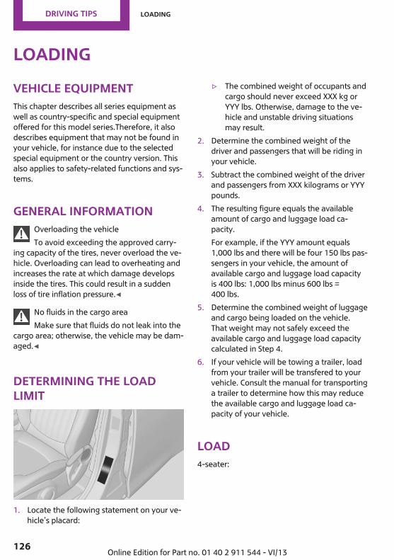
LoadingVehicle equipmentThis chapter describes all series equipment aswell as country-specific and special equipmentoffered for this model series.Therefore, it alsodescribes equipment that may not be found inyour vehicle, for instance due to the selectedspecial equipment or the country version. Thisalso applies to safety-related functions and sys‐tems.
General informationOverloading the vehicleTo avoid exceeding the approved carry‐
ing capacity of the tires, never overload the ve‐hicle. Overloading can lead to overheating andincreases the rate at which damage developsinside the tires. This could result in a suddenloss of tire inflation pressure.◀
No fluids in the cargo areaMake sure that fluids do not leak into the
cargo area; otherwise, the vehicle may be dam‐aged.◀
Determining the loadlimit
1. Locate the following statement on your ve‐hicle’s placard:
▷ The combined weight of occupants andcargo should never exceed XXX kg orYYY lbs. Otherwise, damage to the ve‐hicle and unstable driving situationsmay result.
2. Determine the combined weight of thedriver and passengers that will be riding inyour vehicle.
3. Subtract the combined weight of the driverand passengers from XXX kilograms or YYYpounds.
4. The resulting figure equals the availableamount of cargo and luggage load ca‐pacity.For example, if the YYY amount equals1,000 lbs and there will be four 150 lbs pas‐sengers in your vehicle, the amount ofavailable cargo and luggage load capacityis 400 lbs: 1,000 lbs minus 600 lbs =400 lbs.
5. Determine the combined weight of luggageand cargo being loaded on the vehicle.That weight may not safely exceed theavailable cargo and luggage load capacitycalculated in Step 4.
6. If your vehicle will be towing a trailer, loadfrom your trailer will be transfered to yourvehicle. Consult the manual for transportinga trailer to determine how this may reducethe available cargo and luggage load ca‐pacity of your vehicle.
Load4-seater:
Seite 126
Driving tips Loading
126 Online Edition for Part no. 01 40 2 911 544 - VI/13

5-seater:
The maximum load is the sum of the weight ofthe occupants and the cargo.The greater the weight of the occupants, theless cargo that can be transported.
Stowing cargo▷ Very heavy cargo: when the rear seat is not
occupied, secure each of the outer safetybelts in the opposite buckle.
▷ Heavy cargo: stow as far forward and aslow as possible, ideally directly behind thebackrests.
▷ Cover sharp edges and corners.▷ Do not pile cargo higher than the top edge
of the backrests.▷ If necessary, fold down the rear backrests
to stow cargo.▷ Use the partition net, refer to page 112, to
protect passengers. Make sure that objectscannot penetrate the partition net.
▷ Place protective material around any sharp-edged or pointed objects that could bump
against the rear window while the vehicle isin motion.
MINI Countryman
MINI Paceman
Securing cargoLashing eyes in the cargo area
MINI Countryman
Seite 127
Loading Driving tips
127Online Edition for Part no. 01 40 2 911 544 - VI/13

MINI Paceman
Securing cargo▷ Secure smaller and lighter pieces with tight‐
ening belts or straps.▷ Secure larger and heavier pieces with cargo
straps.Adhere to the information included withthe cargo straps.
▷ Eight mounting eyes are available for fas‐tening the cargo straps.Two of them are located on the side wall ofthe cargo area, arrows 1, and two are lo‐cated on the rear wall of the cargo area, ar‐rows 2.
Securing cargoStow and secure the cargo as described
above; otherwise it may present a danger tothe occupants, for instance during braking andavoidance maneuvers.Do not stow any heavy and hard objects in thepassenger compartment without securingthem; otherwise, they may present a danger tooccupants, for instance during braking andavoidance maneuvers.Never exceed either the approved gross vehicleweight or either of the approved axle loads, asexcessive loads can pose a safety hazard, andmay also place you in violation of traffic safetylaws.Do not secure cargo using the upper LATCHmounting points, refer to page 55; otherwise,these may become damaged.◀
Roof-mounted luggagerackNotesA special rack system is available as an optionalaccessory.
AttachmentFollow the installation instructions for the roof-mounted luggage rack.Ensure that adequate clearance is available forthe movement of the glass sunroof.
LoadingBecause roof racks raise the vehicle's center ofgravity when loaded, they have a major effecton vehicle handling and steering response.Therefore, note the following when loading anddriving:▷ Do not exceed the approved roof/axle
loads and the approved gross vehicleweight.
▷ Distribute the roof load uniformly.▷ The roof load should not be too large in
area.▷ Always load the heaviest pieces on the bot‐
tom.▷ Fasten the roof-mounted luggage securely,
for instance using lashing straps.▷ Do not let objects project into the opening
path of the tailgate.▷ Drive smoothly. Avoid sudden acceleration
and braking maneuvers. Take corners gen‐tly.
Rear luggage rackNotesA special rear rack is available as an optionalaccessory. It does not require a trailer hitch.
Seite 128
Driving tips Loading
128 Online Edition for Part no. 01 40 2 911 544 - VI/13

Follow the installation instructions for the rearrack.
Anchorage pointsMINI Countryman:
MINI Paceman:
The anchorage points are under the covers inthe bumper.Push out the covers on the corresponding cut‐outs.
LoadingWhen loading the vehicle, ensure that the ap‐proved gross vehicle weight and the axle loadsare not exceeded. Adhere to the weight specifi‐cations in the technical data.
Seite 129
Loading Driving tips
129Online Edition for Part no. 01 40 2 911 544 - VI/13
Saving fuelVehicle equipmentThis chapter describes all series equipment aswell as country-specific and special equipmentoffered for this model series.Therefore, it alsodescribes equipment that may not be found inyour vehicle, for instance due to the selectedspecial equipment or the country version. Thisalso applies to safety-related functions and sys‐tems.
General informationYour vehicle contains advanced technology forthe reduction of fuel consumption and emis‐sions.Fuel consumption depends on a number of dif‐ferent factors. The implementation of certainmeasures, driving style and regular mainte‐nance can have an influence on fuel consump‐tion and on the environmental impact.
Remove unnecessary cargoAdditional weight increases fuel consumption.
Remove attached parts following useRemove unneeded auxiliary mirrors, roof orrear luggage racks after use.Attached parts on the vehicle impair the aero‐dynamics and increase the fuel consumption.
Close both windowsOpen windows causes higher air resistance andthus increases fuel consumption.
Check the tire inflation pressureregularlyCheck and, if necessary, correct the tire infla‐tion pressure, refer to page 220, at least twicea month and before starting on a long trip.
Low tire inflation pressure increases rolling re‐sistance and thus raises fuel consumption andtire wear.
Drive away without delayDo not wait for the engine to warm-up whilethe vehicle remains stationary. Start drivingright away, but at moderate engine speeds.This is the fastest way for the cold engine toreach its operating temperature.
Look well ahead when drivingAvoid unnecessary acceleration and braking. Toachieve this, maintain a suitable distance to thevehicle driving ahead of you.Driving smoothly and looking ahead reducesfuel consumption.
Avoid high engine speedsUse 1st gear to get the vehicle in motion. Be‐ginning with 2nd gear, accelerate rapidly. Whenaccelerating, shift up before reaching high en‐gine speeds.When you reach the desired speed, shift intothe highest applicable gear and drive with theengine speed as low as possible and at a con‐stant speed.As a rule: driving at low engine speeds lowersfuel consumption and reduces wear.
Use coasting conditionsWhen approaching a red light, take your footoff the accelerator and coast to a halt in thehighest applicable gear.On a downhill slope, take your foot off the ac‐celerator and coast in a suitable gear.The flow of fuel is interrupted while coasting.
Seite 130
Driving tips Saving fuel
130 Online Edition for Part no. 01 40 2 911 544 - VI/13
Switch off the engine during longerstopsSwitch off the engine during longer stops, e.g.,at traffic lights, railroad crossings or in trafficcongestion.Fuel savings are already achieved after the en‐gine is turned off for as little as 4 seconds.
Automatic Engine Start/Stop FunctionThe Automatic Engine Start/Stop Function auto‐matically switches the engine off during a stop.If the engine is stopped and then started again,fuel consumption and emissions drop com‐pared to an engine that runs permanently.Stopping the engine even for just a few sec‐onds can result in savings.In addition, fuel consumption depends on otherfactors as well, such as driving style, road con‐ditions, maintenance, and environmental fac‐tors.
Switch off any functions that are notcurrently neededFunctions such as seat heating and the rearwindow defroster require a lot of energy andconsume additional fuel, especially in city andstop-and-go traffic.Therefore, switch off these functions if they arenot actually needed.
Have maintenance carried outHave vehicles maintained regularly to achieveoptimal vehicle economy and operating life.Have the maintenance carried out by the serv‐ice center.Please also note the MINI maintenance system,refer to page 237.
Seite 131
Saving fuel Driving tips
131Online Edition for Part no. 01 40 2 911 544 - VI/13

FOLLOW ME.
Online Edition for Part no. 01 40 2 911 544 - VI/13

At a glance
Controls
Driving tips
Navigation
Entertainment
Communication
Mobility
Reference
Online Edition for Part no. 01 40 2 911 544 - VI/13

Navigation systemVehicle equipmentThis chapter describes all series equipment aswell as country-specific and special equipmentoffered for this model series.Therefore, it alsodescribes equipment that may not be found inyour vehicle, for instance due to the selectedspecial equipment or the country version. Thisalso applies to safety-related functions and sys‐tems.
General informationThe navigation system can determine the pre‐cise position of the vehicle, with the aid of sat‐ellites and vehicle sensors, and can reliablyguide you to every entered destination.
Entries in stationary vehicleEnter data only when the vehicle is sta‐
tionary, and always give priority to the applica‐ble traffic regulations in the event of any con‐tradiction between traffic and road conditionsand the instructions issued by the navigationsystem. Failure to take to this precaution canplace you in violation of the law and put vehicleoccupants and other road users in danger.◀
Opening the navigation system1. "Navigation"
During destination guidance, the arrow or mapview appears on the Control Display.
Navigation dataInformation on navigation data1. "Navigation"2. Open "Options".3. "Navigation system version"
Information is displayed on the data ver‐sion.
Updating the navigation data
General informationNavigation data are stored in the vehicle andcan be updated.Current navigation data and the authorizationcode are available from your service center.▷ Depending on the data volume, a data up‐
date may take several hours.▷ Update during the trip to preserve battery.▷ The status of the update can be viewed.▷ The data are stored in the vehicle.▷ After the updating process is complete, the
system restarts.▷ Remove the medium with the navigation
data after the update.
Performing the update1. Depending on the equipment: insert the
USB device with the navigation data intothe USB interface in the glove compartmentor in the USB audio interface.
2. Follow the instructions on the Control Dis‐play.
3. Enter the authorization code of the USB de‐vice with the navigation data.
4. Drive off.The update starts after the authorization codeis entered.
Seite 134
Navigation Navigation system
134 Online Edition for Part no. 01 40 2 911 544 - VI/13

When the update is completed, the system re‐starts.
Seite 135
Navigation system Navigation
135Online Edition for Part no. 01 40 2 911 544 - VI/13

Destination entryVehicle equipmentThis chapter describes all series equipment aswell as country-specific and special equipmentoffered for this model series.Therefore, it alsodescribes equipment that may not be found inyour vehicle, for instance due to the selectedspecial equipment or the country version. Thisalso applies to safety-related functions and sys‐tems.
At a glanceIn entering your destination, it is possible to se‐lect from the following options:▷ Enter the destination manually, see below.▷ Select the destination from the address
book, refer to page 138.▷ Last destinations, refer to page 139.▷ Special destinations, refer to page 140.▷ Destination entry via map, refer to
page 141.▷ Using the home address as the destination,
refer to page 139.▷ Destination entry by voice, refer to
page 142.
Manual destination en‐tryGeneral informationThe system supports you in entering streetnames and house numbers by automaticallycompleting the entry and providing entry com‐parisons, refer to page 25.Stored town/city and street names can becalled up quickly.
▷ If the existing entries should not bechanged, the entries for the state/provinceand town/city can be skipped.
▷ Destination guidance is started to the town/city center if no street is entered.
Entering a state/province1. "Navigation"2. "Enter address"
3. Select "State/Province" or the displayedstate/province.
Entering a town/city1. Select "Town/City/Postal Code" or the dis‐
played town/city.
2. Select letters, if necessary.The list is narrowed down further with eachentry.
3. Move the MINI joystick to the right.4. Select the name of the town/city from the
list.
Seite 136
Navigation Destination entry
136 Online Edition for Part no. 01 40 2 911 544 - VI/13

If there are several towns/cities with the samename:
1. Change to the list of town/city names.2. Highlight the town/city.3. Select the town/city.
Entering the postal code1. Select "Town/City/Postal Code" or the dis‐
played town/city.2. Select the symbol.3. Select the digits individually.4. Change to the list of postal codes and
towns/cities.5. Highlight the entry.6. Selecting an entry.
The associated destination town/city is dis‐played.
Entering a street and intersection1. Select "Street" or the displayed street.2. Enter a street and intersection in the same
way as you would enter a town/city.If there are several streets with the same name:
1. Change to the list of street names.2. Highlight the street.3. Select the street.
Alternative: enter the street addressand house number1. Select "Street" or the displayed street.2. Enter the street as you would the town/city.3. "House number"4. Select the numbers.5. Change to the list of house numbers.6. Select a house number or range of house
numbers.
Street does not exist in the destinationcity/townThe desired street does not exist in the speci‐fied city/town because it belongs to anotherpart of the city/town.
1. "Navigation"2. "Enter address"3. Select "Street" or the displayed street.4. Change to the list of street names.5. Select "In" with the state/province currently
displayed.All streets of the selected state/province areoffered. The associated town/city is dis‐played after the street name.
6. Select the letters.7. Change to the list of street names.8. Highlight the street.9. Select the street.
Starting destination guidance afterentering the destination1. "Accept destination"2. "Start guidance" or "Add as another
destination"
Seite 137
Destination entry Navigation
137Online Edition for Part no. 01 40 2 911 544 - VI/13

Add a destination as a further destination,refer to page 144.
Address bookCreate contacts, refer to page 187.
Selecting a destination from theaddress book1. "Navigation"2. "Address book"
Contacts with addresses are displayed ifthese addresses have been checked as des‐tinations in the contacts.If the contacts with addresses from the mo‐bile phone are not displayed, they firstneed to be checked as destinations, refer topage 189.
3. Select a contact in the list or, if desired, with"A-Z search".
4. "Business address" or "Home address"
Storing the destination in the addressbookAfter entering the destination, store the desti‐nation in the address book.
1. "Navigation"2. "Map"3. "Guidance"4. Open "Options".5. "Store as new contact" or "Add to existing
contact"
6. Select an existing contact, if available.7. "Business address" or "Home address"8. Enter "Last name" and, if necessary, "First
name".9. "Store in vehicle"
Storing the positionThe current position can be stored in the ad‐dress book.
1. "Navigation"2. Open "Options".
Seite 138
Navigation Destination entry
138 Online Edition for Part no. 01 40 2 911 544 - VI/13

3. "Store position as contact" or "Add positionto contact"
4. Depending on the selection, choose an ex‐isting contact from the list. Select the typeof address and enter the first and lastname.
5. "Store in vehicle"
Editing or deleting an address1. "Navigation"2. "Address book"3. Highlight the entry.4. Open "Options".5. "Edit in Contacts" or "Delete entry"
Using the home address as thedestinationThe home address must be stored. Specify thehome address, refer to page 188.
1. "Navigation"2. "Address book"
3. "Home"
4. "Start guidance"
Last destinationsAt a glanceThe destinations previously entered are storedautomatically. These destinations can be calledup and used as a destination for destinationguidance.
Calling up the last destination1. "Navigation"2. "Last destinations"
Starting destination guidance1. "Navigation"2. "Last destinations"3. Select the destination.4. "Start guidance"
Seite 139
Destination entry Navigation
139Online Edition for Part no. 01 40 2 911 544 - VI/13

Editing the destinationDestinations can be edited, for example tochange the house number of an existing entry.
1. "Navigation"2. "Last destinations"3. Highlight the destination.4. Open "Options".5. "Edit destination"
Deleting the last destinations1. "Navigation"2. "Last destinations"3. Highlight the destination.4. Open "Options".5. "Delete entry" or "Delete all last
destinations"
Special destinationsGeneral informationEven with the latest navigation data, informa‐tion on individual special destinations mayhave changed; for example, gas stations mightnot be in operation.
Opening the search for specialdestinationsSelection of special destinations, such as hotelsor tourist attractions.
1. "Navigation"2. "Points of Interest"3. Select the search function.
A-Z search1. "A-Z search"2. "Town/City"3. Select or enter the town/city.4. "Category"
5. Select the category.6. "Category details"
For some special destinations, it may bepossible to select multiple category details.Move the MINI joystick to the left to leavethe category details.
7. "Keyword"8. Enter the keyword.
A list of the special destinations is dis‐played.
9. Select a special destination.Details are displayed.If multiple details are stored, you can leafthrough the pages.If a phone number is available, a connec‐tion can be established if necessary.
10. Select the symbol.11. "Start guidance" or "Add as another
destination"Add a destination as a further destination,refer to page 144.
Category search1. "Category search"2. "Search destination"3. Select or enter the town/city.4. "Category"5. Select the category.6. "Category details"
For some special destinations, it may bepossible to select multiple category details.Move the MINI joystick to the left to leavethe category details.
7. "Start search"A list of the special destinations is dis‐played.
8. Select a special destination.Details are displayed.If multiple details are stored, you can leafthrough the pages.
Seite 140
Navigation Destination entry
140 Online Edition for Part no. 01 40 2 911 544 - VI/13

If a phone number is available, a connec‐tion can be established if necessary.
9. Select the symbol.10. "Start guidance" or "Add as another
destination"Add a destination as a further destination,refer to page 144.
Position of special destinationsWhen entering the search location, various op‐tions can be selected.▷ "At current location"▷ "At destination"▷ "At different location"▷ If destination guidance is active: "Along
route"
Starting the search for specialdestinations1. "Start search"2. A list of the special destinations is dis‐
played.▷ "At current location"
The special destinations are listed ac‐cording to their distance and are dis‐played with a directional arrow pointingto the destination.
▷ "At destination", "At different location","Along route"Special destinations are listed accordingto their distance from the locationwhere the search is being performed.
▷ Destinations of the selected categoryare displayed in the map view as sym‐bols. The display depends on the mapscale and the category.
3. Highlight the special destination.4. Select a special destination.5. Select the symbol.6. "Start guidance" or "Add as another
destination"The direct distance to destination is dis‐played.
Displaying special destinations in themapTo display symbols of the special destinations inthe map view:
1. "Navigation"2. "Map"3. Open "Options".4. "Display Points of Interest"
5. Select the setting.
Destination entry by mapGeneral informationIf only the location of the destination town/cityor street is known, the destination can be en‐tered using the map.
Seite 141
Destination entry Navigation
141Online Edition for Part no. 01 40 2 911 544 - VI/13
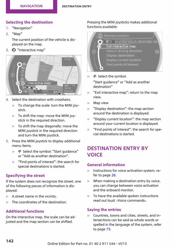
Selecting the destination1. "Navigation"2. "Map"
The current position of the vehicle is dis‐played on the map.
3. "Interactive map"
4. Select the destination with crosshairs.▷ To change the scale: turn the MINI joy‐
stick.▷ To shift the map: move the MINI joy‐
stick in the required direction.▷ To shift the map diagonally: move the
MINI joystick in the required directionand turn the MINI joystick.
5. Press the MINI joystick to display additionalmenu items.▷ Select the symbol: "Start guidance"
or "Add as another destination".▷ "Find points of interest": the search for
special destinations is started.
Specifying the streetIf the system does not recognize the street, oneof the following pieces of information is dis‐played:▷ A street name in the vicinity.▷ The coordinates of the destination.
Additional functionsOn the interactive map, the scale can be ad‐justed and the map section can be shifted.
Pressing the MINI joysticks makes additionalfunctions available:
▷ Select the symbol."Start guidance" or "Add as anotherdestination"
▷ "Exit interactive map": return to the mapview.
▷ Map view▷ "Display destination": the map section
around the destination is displayed.▷ "Display current location": the map section
around your current location is displayed.▷ "Find points of interest": the search for spe‐
cial destinations is started.
Destination entry byvoiceGeneral information▷ Instructions for voice activation system, re‐
fer to page 26.▷ When making a destination entry by voice,
you can change between voice activationand the onboard monitor.
▷ To have the available spoken instructionsread out loud: ›Voice commands‹.
Saying the entries▷ Countries, towns and cities, streets, and in‐
tersections can be said as whole words orspelled in the language of the system, referto page 73.
Seite 142
Navigation Destination entry
142 Online Edition for Part no. 01 40 2 911 544 - VI/13

Example: to enter a town/city in a US statesas a whole word, the language of the sys‐tem must be English.
▷ Spell the entry if the spoken language andthe language of the system differ.
▷ Say the letters smoothly, and avoid exag‐gerating the pronunciation and insertinglengthy pauses between the letters.
▷ The methods of entry depend on the navi‐gation data in use and the country and lan‐guage settings.
Entering a town/city separatelyThe town/city can be said as a complete word.
1. Press the button on the steeringwheel.
2. ›City‹ or ›Spell city‹3. Wait for the system to prompt you for the
town/city.4. Say the name of the town/city, or name at
least the first three letters.5. Select a location:
▷ Select a recommended town/city: ›Yes‹.▷ Select a different town/city: ›New
entry‹.▷ Select an entry: ›Entry ...‹, for instance,
entry 2.▷ Spell an entry: ›Spell city‹.
6. Continue making the entry as prompted bythe system.
If there are several towns/cities with the samename:Towns/cities of the same name are grouped ina list and displayed as one location followed byan ellipsis.
1. Select an entry: ›Yes‹ or ›Entry ...‹, e. g., En‐try 2.
2. Select the desired town/city.The town/city can also be selected from thelist on the onboard monitor:
Turn the MINI joystick until the destinationtown/city is selected and press theMINI joystick.
Entering a street or intersectionseparatelyEnter a street and intersection in the same wayas you would enter a town/city.
Entering a house number separatelyDepending on the data in the navigation sys‐tem, house numbers up to number 2,000 canbe entered.
1. ›House number‹2. Say the house number.3. ›Yes‹ to confirm the house number.4. ›Accept destination‹
Starting destination guidance›Start guidance‹
Adding further intermediatedestinations›Add as another destination‹Further intermediate destinations can beadded.
Storing a destinationThe destination is automatically added to thelist of last destinations.
Planning a trip with in‐termediate destinationsNew tripVarious intermediate destinations can be en‐tered for a trip. The trip destination needs to beentered first, destination entry, refer topage 136.
Seite 143
Destination entry Navigation
143Online Edition for Part no. 01 40 2 911 544 - VI/13

Entering intermediate destinationsA maximum of 30 intermediate destinationscan be entered for a trip.
1. "Navigation"2. Select the type of destination entry and en‐
ter the intermediate destination.
3. "Add as another destination"
4. Select the position where the intermediatedestination is to be inserted.
Starting the tripAfter all intermediate destinations have beenentered:"Start guidance"
Seite 144
Navigation Destination entry
144 Online Edition for Part no. 01 40 2 911 544 - VI/13

Destination guidanceVehicle equipmentThis chapter describes all series equipment aswell as country-specific and special equipmentoffered for this model series.Therefore, it alsodescribes equipment that may not be found inyour vehicle, for instance due to the selectedspecial equipment or the country version. Thisalso applies to safety-related functions and sys‐tems.
Starting destinationguidance1. "Navigation"2. Make a destination entry, refer to
page 136.3. "Accept destination"4. "Start guidance"The route is shown on the Control Display.The distance to the destination/intermediatedestination and the estimated time of arrivalare displayed in the map view.The arrow view may appear on the Control Dis‐play.
Terminating destinationguidance1. "Navigation"2. "Map"3. Select the symbol.4. "Stop guidance"
Continuing destinationguidanceIf the destination was not reached during thelast trip, destination guidance can be resumed."Resume guidance"
Route criteriaGeneral information▷ The route calculated can be influenced by
selecting certain criteria.▷ The route criteria can be changed when the
destination is entered and during destina‐tion guidance.
▷ Road types are part of the navigation dataand are taken into consideration whenplanning a route, e.g., avoid highways.
▷ The recommended route may differ fromthe route you would take based on per‐sonal experience.
▷ The settings are stored for the remote con‐trol currently in use.
▷ Destination guidance with traffic bulletins,refer to page 151.
Changing the route criteria1. "Navigation"2. "Map"3. "Route preference"4. Select the criterion:
▷ "Fast route": time-optimized route,being a combination of the shortestpossible route and the fastest roads.
▷ "Efficient route": optimized combi‐nation of the fastest and shortest route.
Seite 145
Destination guidance Navigation
145Online Edition for Part no. 01 40 2 911 544 - VI/13

▷ "Short route": short distance, irre‐spective of how fast or slow progresswill be.
▷ "Alternative routes": if available, alter‐native routes are suggested during ac‐tive destination guidance.
5. Select additional criteria for the route, ifnecessary. Where possible, the selected cri‐teria are avoided on the route.▷ "Avoid highways": highways are
avoided wherever possible.▷ "Avoid toll roads": toll roads are
avoided wherever possible.▷ "Avoid ferries": ferries are avoided
where possible.
RouteDifferent views of the route are available duringdestination guidance:▷ Arrow view.▷ List of route sections.▷ Map view, refer to page 148.
Arrow viewThe following information is displayed duringdestination guidance:▷ Large arrow: indicates the current direction
of travel.▷ Street name of the road currently being
driven on.
▷ Small arrow: indicates the next change indirection.
▷ Intersection view.▷ Lane information.▷ Traffic bulletins.▷ Distance to the next change in direction.▷ Street name at the next change in direc‐
tion.
Lane informationOn multi-lane roads, the recommended lanesare marked in the arrow view by a triangle.▷ Solid triangle: best lane.▷ Empty triangle: possible lane. However, an‐
other lane change may be needed shortly.
Displaying a list of route sectionsWhen destination guidance is active, a list ofthe route sections can be displayed. The drivingdistance and traffic bulletins are displayed foreach route section.
1. "Navigation"2. "Route information"
3. Highlight a route section.
Bypassing a section ofthe routeCalculate a new route for a route section.
1. "Navigation"2. "Route information"
Seite 146
Navigation Destination guidance
146 Online Edition for Part no. 01 40 2 911 544 - VI/13

3. "New route for"
4. Turn the MINI joystick. Enter the number ofkilometers within which you would like toreturn to the original route.
5. Press the MINI joystick.
Resuming the original routeIf the route section should no longer be by‐passed:
1. "Navigation"2. "Route information"3. "New route for:"4. "Remove blocking"
Gas station recommenda‐tionThe remaining range is calculated and gas sta‐tions along the route are displayed if needed.Even with the latest navigation data, informa‐tion on individual special destinations mayhave changed; for example, gas stations mightnot be in operation.
1. "Navigation"2. "Route information"3. "Recommended refuel"
A list of the gas stations is displayed.4. Highlight a gas station.5. Select the gas station.
6. Select the symbol.7. "Start guidance": destination guidance to
the selected gas station is started."Add as another destination": the gas sta‐tion is added to the route.
Destination guidancethrough voice instruc‐tionsSwitching spoken instructions on/offThe spoken instructions can be switched on oroff during destination guidance.The setting is stored for the remote control cur‐rently in use.
1. "Navigation"2. "Map"3. Select the symbol.
Symbol Function
The spoken instructions are switchedon.
Spoken instructions are switched off.
Repeating a spoken instruction1. "Navigation"2. "Map"3. Highlight the symbol.4. Press the MINI joystick twice.
Volume of spoken instructionsTurn the volume knob while giving an instruc‐tion until the desired volume is set.
Seite 147
Destination guidance Navigation
147Online Edition for Part no. 01 40 2 911 544 - VI/13

This volume is independent of the volume ofthe audio sources.The setting is stored for the remote control cur‐rently in use.
Map viewSelecting the map view1. "Navigation"2. "Map"
At a glance
1 Function bar2 Route section with traffic obstruction3 Traffic sign for traffic obstruction4 Planned route5 Current location6 Upper status field7 Lower status field
Lines in the mapStreets and routes are displayed in differentcolors and styles depending on their classifica‐
tion. Dashed lines represent railways and ferryconnections. Country borders are indicated bythin lines.
Traffic obstructionsSmall triangles along the planned route indicateroute sections with traffic obstructions, de‐pending on the map scale. The direction of thetriangles indicates the direction of the obstruc‐tion.The traffic signs indicate the significance of theobstruction.▷ Red traffic sign: the obstruction affects the
planned route or direction.▷ Grey traffic sign: the obstruction does not
affect the planned route or direction.Traffic bulletins, refer to page 149.
Planned routeAfter destination guidance is started, the plan‐ned route is displayed on the map.
Status fieldsTo show/hide: press the MINI joystick.▷ Upper status field: time, telephone, and en‐
tertainment details.▷ Lower status field: symbol for active desti‐
nation guidance, status of traffic bulletins,time of arrival, and distance to destination.
Function barThe following functions are available in thefunction bar:Symbol Function
Start/end destination guidance.
Switch spoken instructions on/off.
Change the route criteria.
Search for a special destina‐tion.
Seite 148
Navigation Destination guidance
148 Online Edition for Part no. 01 40 2 911 544 - VI/13

Symbol Function
Display traffic bulletins.
Open the interactive map.
Adjust the map views.
Adjust the arrow view.
Change the scale.
Changing the map section "Interactive map"
▷ To shift the map: move the MINI joystick inthe required direction.
▷ To shift the map diagonally: move theMINI joystick in the required direction andturn the MINI joystick.
Changing the scale1. Select the symbol.2. To change the scale: turn the MINI joystick.
Automatically scaled map scaleIn the map view facing north, turn the MINI joy‐stick in any direction until the AUTO is dis‐played for the scale. The entire route betweenthe current location and the destination is dis‐played on the map.
Settings for the map viewThe settings are stored for the remote controlcurrently in use.
1. "Navigation"2. "Map"3. Open "Options".4. "Settings"5. To set the map view:
▷ "Day/night mode"Select and create the necessary settingsdepending on the light conditions.
"Traffic conditions/gray map" active:the setting is disregarded.
▷ "Traffic conditions/gray map"The map is optimized for displayingtraffic bulletins.Symbols for the special destinations areno longer displayed.
Arrow viewWhen destination guidance is activated, the ar‐row view can additionally be displayed in themap view on the right side of the display.
1. "Navigation"2. Open "Options".3. "Arrow display on map"
The arrow view is shown on the map.
Traffic bulletinsAt a glance▷ Display the traffic bulletins from radio sta‐
tions that broadcast the TI Traffic Informa‐tion of a traffic information service. Infor‐mation on traffic obstructions and hazardsis updated continuously.
▷ The traffic bulletins are indicated on themap by symbols.
The symbol in the function bar of the mapview turns red if there are traffic bulletins thataffect the calculated route.
Seite 149
Destination guidance Navigation
149Online Edition for Part no. 01 40 2 911 544 - VI/13
Real Time Traffic Information End-UserProvisionsCertain MINI models equipped with navigationhave the capability to display real-time trafficinformation. If your system has this capabilitythe following additional terms and conditionsapply:An End-User shall no longer have the right touse the Traffic Data in the event that the End-User is in material breach of the terms and con‐ditions contained herein.A. Total Traffic Network, a division of ClearChannel Broadcasting, Inc. (“Total Traffic Net‐work”) holds the rights to the traffic incidentdata and RDS-TMC network through which it isdelivered. You may not modify, copy, scan oruse any other method to reproduce, duplicate,republish, transmit or distribute in any way anyportion of traffic incident data. You agree to in‐demnify, defend and hold harmless MINI ofNorth America, LLC. (“MINI NA”) and Total Traf‐fic Network, Inrix, Inc (and their affiliates)against any and all claims, damages, costs orother expenses that arise directly or indirectlyout of (a) your unauthorized use of the trafficincident data or the RDS-TMC network, (b) yourviolation of this directive and/or (c) any unau‐thorized or unlawful activities by you in con‐nection herewith.B. Total Traffic Network traffic data is informa‐tional only. User assumes all risk of use. TotalTraffic Network, MINI NA, and their suppliersmake no representations about content, trafficand road conditions, route usability, or speed.C. The licensed material is provided to license“as is,” and “where is”. Total Traffic Network,including, but not limited to, any and all thirdparty providers of any of the licensed material,expressly disclaims, to the fullest extent permit‐ted by law, all warranties or representationswith respect to the licensed material (including,without limitation, that the licensed materialwill be error-free, will operate without interrup‐tion or that the traffic data will be accurate), ex‐press, implied or statutory, including, without
limitation, the implied warranties of merchant‐ability, non-infringement fitness for a particularpurpose, or those arising from a course of deal‐ing or usage of trade.D. Neither Total Traffic Network, Inrix, Inc. orMINI NA will be liable to you for any indirect,special, consequential, exemplary, or incidentaldamages (including, without limitation, lostrevenues, anticipated revenues, or profits relat‐ing to the same) arising from any claim relatingdirectly or indirectly to use of the traffic data,and even if Total Traffic Network, Inrix, Inc., orMINI NA are aware of the possibility of suchdamages. These limitations apply to all claims,including, without limitation, claims in contractand tort (such as negligence, product liabilityand strict liability). Some states do not allow theexclusion or limitation of incidental or conse‐quential damages, so those particular limita‐tions may not apply to you.
Switching the reception on/off1. "Navigation"2. Open "Options".3. "Receive Traffic Info"
Open the traffic bulletins1. "Navigation"2. "Map"3. "Traffic Info"
First, traffic bulletins for the calculatedroute are displayed.The traffic bulletins are sorted by their dis‐tance from the current position of the vehi‐cle.
4. Select a traffic bulletin. "More information": display additional
information.5. Scroll to the next or previous traffic bulletin
if required.
Traffic bulletins on the map"Traffic conditions/gray map" active:
Seite 150
Navigation Destination guidance
150 Online Edition for Part no. 01 40 2 911 544 - VI/13

The Control Display changes to a black andwhite display. This enables a better view of thetraffic bulletins. The day/night mode is disre‐garded in this setting. Symbols and special des‐tinations are not displayed.
1. "Navigation"2. "Map"3. Open "Options".4. "Settings"5. "Traffic conditions/gray map"
Symbols in the map viewDepending on the scale of the map and the lo‐cation of the traffic obstruction along the route,the symbols for the traffic obstructions are dis‐played.
Additional information in the map viewDepending on the map scale, a traffic obstruc‐tion's length, direction, and impact are dis‐played in the map using triangles or gray barsalong the calculated route.▷ Red: traffic congestion.▷ Orange: stop-and-go traffic.▷ Yellow: heavy traffic.▷ Green: clear roads.▷ Gray: general traffic bulletins such as road
construction.The displayed information depends on the par‐ticular traffic information service.
Filtering traffic bulletinsYou can set which traffic bulletins appear onthe map.
1. "Navigation"2. "Map"3. Open "Options".
4. "Traffic Info categories"5. Select the desired category.
Traffic bulletins of the selected category aredisplayed on the map.▷ Traffic bulletins that are relevant to the
route are always shown.▷ For your own safety, traffic bulletins that
notify you of potentially dangerous situa‐tions cannot be hidden.
Destination guidance with trafficbulletins
General informationDetour suggestions from the navigation systemcan be manually accepted when using semi-dy‐namic destination guidance. When using dy‐namic destination guidance, they are automati‐cally accepted for route guidance.
Semi-dynamic destination guidanceWhen traffic bulletin reception is switched on,semi-dynamic destination guidance is active.The destination guidance system takes theavailable traffic bulletins into account. A mes‐sage is displayed depending on the route, thetraffic bulletins, and the possible detour routes.If possible, a detour is offered in case of trafficobstructions. In addition, distance and time dif‐ferences between the original route and thedetour are displayed.
Accepting the detour "Detour"
Seite 151
Destination guidance Navigation
151Online Edition for Part no. 01 40 2 911 544 - VI/13

In the event of special hazards, e. g., objects onthe road, a message is displayed without a de‐tour suggestion.Detours can also be accepted if the traffic mes‐sages are called up in the list.
1. "Navigation"2. "Map"3. "Traffic Info"4. "Detour information"5. "Detour"
Dynamic destination guidanceThe route is automatically changed in the eventof traffic obstructions.▷ The system does not point out traffic ob‐
structions along the original route.▷ Traffic bulletins continue to be displayed on
the map.▷ Depending on road type and the kind and
extent of the traffic obstruction, the calcu‐lated route may lead through the traffic ob‐struction.
▷ Dangerous situations are displayed regard‐less of the setting.
Activating dynamic destination guidance1. "Navigation"2. Open "Options".3. "Dynamic guidance"
Seite 152
Navigation Destination guidance
152 Online Edition for Part no. 01 40 2 911 544 - VI/13

What to do if...Vehicle equipmentThis chapter describes all series equipment aswell as country-specific and special equipmentoffered for this model series.Therefore, it alsodescribes equipment that may not be found inyour vehicle, for instance due to the selectedspecial equipment or the country version. Thisalso applies to safety-related functions and sys‐tems.
What to do if...▷ The current transmission position cannot be
displayed?The vehicle is located in an unrecognizedregion, is in a poor reception area, or thesystem is currently determining the posi‐tion. Reception is usually best when youhave an unobstructed view of the sky.
▷ The destination without street informationis not used for route guidance?When city has been input, no downtowncan be determined. Input any street in theselected city and start destination guid‐ance.
▷ The destination is not used for route guid‐ance?The destination data are not contained inthe navigation data. Select a destinationthat is as close as possible to the original.
▷ Letters for destination input cannot be se‐lected?The stored data do not contain the data ofthe destination. Select a goal that is as closeas possible to the original.
▷ Is the map displayed in shades of gray?"Traffic conditions/gray map" active:
The Control Display changes to a black andwhite display. This enables a better view ofthe traffic bulletins.
▷ Spoken instructions are no longer outputduring route guidance in front of intersec‐tions?The area has not yet been fully recorded, oryou have left the recommended route andthe system requires a few seconds to calcu‐late a new route suggestion.
▷ Does the navigation system fail to react toentries?If the battery was disconnected, it takes upto 10 minutes for the system to becomingfunctional again.
Seite 153
What to do if... Navigation
153Online Edition for Part no. 01 40 2 911 544 - VI/13

ROCK ME.
Online Edition for Part no. 01 40 2 911 544 - VI/13

At a glance
Controls
Driving tips
Navigation
Entertainment
Communication
Mobility
Reference
Online Edition for Part no. 01 40 2 911 544 - VI/13

ToneVehicle equipmentThis chapter describes all series equipment aswell as country-specific and special equipmentoffered for this model series.Therefore, it alsodescribes equipment that may not be found inyour vehicle, for instance due to the selectedspecial equipment or the country version. Thisalso applies to safety-related functions and sys‐tems.
General informationThe sound settings are stored for the remotecontrol currently in use.
Treble, bass, balance,and fader▷ "Treble": treble adjustment.▷ "Bass": depth adjustment.▷ "Balance": left/right volume distribution.▷ "Fader": front/rear volume distribution.
Setting treble, bass, balance, and fader1. "CD/Multimedia", "Radio" or "Settings"2. "Tone"
3. Select the desired tone settings.
4. To set: turn the MINI joystick.5. To save: press the MINI joystick.
Volume▷ "Speed volume": speed-dependent volume
control.▷ "PDC": volume of the PDC signal compared
to the entertainment sound output.▷ "Gong": volume of the signal, such as the
safety belt reminder, compared to the en‐tertainment sound output.
Bluetooth mobile phone preparation package▷ "Microphone": volume of the microphone
during a phone call.▷ "Loudspeak.": volume of the loudspeakers
during a phone call.The following volumes are only stored for therespective paired telephone: "Microphone","Loudspeak.".
Adjusting the volume1. "CD/Multimedia", "Radio" or "Settings"2. "Tone"3. "Volume settings"
Seite 156
Entertainment Tone
156 Online Edition for Part no. 01 40 2 911 544 - VI/13

4. Select the desired volume setting.
5. To set: turn the MINI joystick.6. To save: press the MINI joystick.
Resetting the tone set‐tingsAll tone settings can be reset to the default set‐ting.
1. "CD/Multimedia", "Radio" or "Settings"2. "Tone"3. "Reset"
Seite 157
Tone Entertainment
157Online Edition for Part no. 01 40 2 911 544 - VI/13
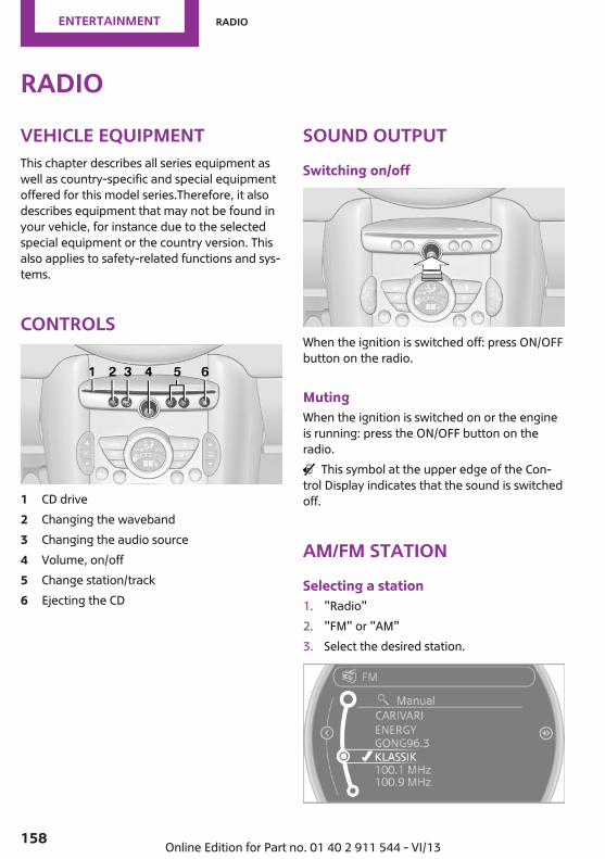
RadioVehicle equipmentThis chapter describes all series equipment aswell as country-specific and special equipmentoffered for this model series.Therefore, it alsodescribes equipment that may not be found inyour vehicle, for instance due to the selectedspecial equipment or the country version. Thisalso applies to safety-related functions and sys‐tems.
Controls
1 CD drive2 Changing the waveband3 Changing the audio source4 Volume, on/off5 Change station/track6 Ejecting the CD
Sound outputSwitching on/off
When the ignition is switched off: press ON/OFFbutton on the radio.
MutingWhen the ignition is switched on or the engineis running: press the ON/OFF button on theradio.
This symbol at the upper edge of the Con‐trol Display indicates that the sound is switchedoff.
AM/FM stationSelecting a station1. "Radio"2. "FM" or "AM"3. Select the desired station.
Seite 158
Entertainment Radio
158 Online Edition for Part no. 01 40 2 911 544 - VI/13

All saved stations are stored for the remotecontrol currently in use.
Changing the stationTurn and press the MINI joystick.or
Press the buttonorPress the buttons on the steering wheel.
Storing a station1. "Radio"2. "FM" or "AM"3. Highlight the desired station.
4. Press the MINI joystick.5. Select the desired memory location.Press and hold the MINI joystick to store a sta‐tion that is displayed in the station list but is notbeing played.The stations are stored for the remote controlcurrently in use.
Selecting a station manuallyStation selection via the frequency.
1. "Radio"2. "FM" or "AM"3. "Manual"4. To select a frequency: turn the MINI joy‐
stick.
To save a station: press and hold theMINI joystick.
RDSRDS broadcasts additional information, such asthe station name, in the FM wave band.
Switching the RDS on/off1. "Radio"2. "FM"3. Open "Options".4. "RDS"
The setting is stored for the remote control cur‐rently in use.
HD Radio™ receptionMany stations broadcast both analog and digi‐tal signals.License conditionsHD Radio Technology manufactured under li‐cense from iBiquity Digital Corporation. U.S.and Foreign Patents. HD Radio™ and the HD,HD Radio, and Arc logos are proprietary trade‐marks of iBiquity Digital Corp.
Seite 159
Radio Entertainment
159Online Edition for Part no. 01 40 2 911 544 - VI/13

Activating/deactivating digital radioreception1. "Radio"2. "FM" or "AM"3. Open "Options".4. "HD Radio Reception"The setting is stored for the remote control cur‐rently in use.
This symbol is displayed in the status linewhen the audio signal is digital.When tuning to a station with a digital signal, itmay take several seconds for the station to beplayed back in digital quality.Note on HD stations whose station name endsin ...HD or HD1:In areas in which the station is not continuouslyreceived in digital mode, the playback switchesbetween analog and digital reception. In thiscase, switch off digital radio reception.Note on HD multicast stations whose stationname ends in ...HD2, ...HD3, ...:In areas in which the station is not continuouslyreceived in digital mode, the audible signalmay be interrupted for several seconds. This isreception related.
Displaying additional informationSome stations broadcast additional informationon the current track, such as the name of theartist.
1. Select the desired station.2. Open "Options".3. "Station info"
Selecting a substation This symbol indicates that a main station
also broadcasts additional substations. The sta‐tion name of the main station ends in HD1. Sta‐tion names of the substations end in HD2, HD3,etc.
1. Select the desired station.
2. Press the controller.3. Select the substation.When reception is poor, the substation ismuted.
Satellite radioGeneral informationThe channels are offered in predefined pack‐ages. The packages must be enabled by tele‐phone.
Navigation bar overview
Symbol Function
Change the list view.
Select the category.
Direct channel entry
Timeshift
Open the My Favorites category/open a favorite.
Manage the favorites.
Traffic Jump
Managing a subscriptionTo be able to enable or unsubscribe from thechannels, you must have reception. It is usuallyat its best when you have an unobstructed viewof the sky. The channel name is displayed in thestatus line.
Enabling channelsThe Unsubscribed Channels category containsall disabled channels.
1. "Radio"2. "Satellite radio"
Seite 160
Entertainment Radio
160 Online Edition for Part no. 01 40 2 911 544 - VI/13

3. "Category"
4. Select the Unsubscribed Channels category.5. Select the desired channel.
The phone number and an electronic serialnumber, ESN, are displayed.
6. Select the phone number to have the chan‐nel enabled.
You can unsubscribe from the channels againvia this phone number.
Unsubscribing from channels1. "Radio"2. "Satellite radio"3. Open "Options".4. "Manage subscription"
5. The phone number and an electronic serialnumber, ESN, are displayed.
6. Call Sirius to unsubscribe from the channels.
Selecting channelsYou can only listen to enabled channels.The selected channel is stored for the remotecontrol currently in use.
Via the onboard monitor1. "Radio"2. "Satellite radio"3. Select "All channels" or the desired cate‐
gory.4. Select the desired channel.
Via the buttons in the area of the CDplayer
Press the button.The next channel is selected.
Via direct channel entry1. "Radio"2. "Satellite radio"3. "Set channel"4. Turn the MINI joystick until the desired
channel is reached and press the MINI joy‐stick.
Seite 161
Radio Entertainment
161Online Edition for Part no. 01 40 2 911 544 - VI/13
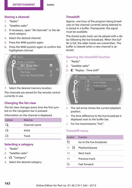
Storing a channel1. "Radio"2. "Satellite radio"3. If necessary, open "All channels" or the de‐
sired category.4. Select the desired channel.5. Press the MINI joystick again.6. Press the MINI joystick again to confirm the
highlighted channel.
7. Select the desired memory location.The channels are stored for the remote controlcurrently in use.
Changing the list viewThe list view changes every time the first sym‐bol on the navigation bar is pressed.Information on the channel is displayed.Symbol Meaning
Channel name
Artist
Track
Selecting a category1. "Radio"2. "Satellite radio"3. "Category"4. Select the desired category.
TimeshiftApprox. one hour of the program being broad‐cast on the channel currently being listened tois stored in a buffer. Prerequisite: the signalmust be available.The stored audio track can be played with a de‐lay following the live broadcast. When the buf‐fer is full, the older tracks are overwritten. Thebuffer is cleared when a new channel is se‐lected.
Opening the timeshift function1. "Radio"2. "Satellite radio"3. "Replay - Time shift"
▷ The red arrow shows the current playbackposition.
▷ The time difference to the live broadcast isdisplayed next to the buffer bar.
▷ For live transmissions "live".
Timeshift menu
Symbol Function
Go to the live broadcast
Playback/pause
Next track
Previous track
Fast forward
Seite 162
Entertainment Radio
162 Online Edition for Part no. 01 40 2 911 544 - VI/13

Symbol Function
Reverse
Automatic timeshift deactivated/activated
Automatic timeshiftWhen the function is activated, audio playbackis stopped automatically in the event of:▷ Incoming and outgoing telephone calls.▷ Activation of the voice activation system.▷ Muting.The audio playback then continues with a timedelay.
Activating1. "Radio"2. "Satellite radio"3. "Replay - Time shift"4. "Automatic time shift"
Deactivating "Automatic time shift"
Storing favoritesUp to 30 favorites can be stored in the favoriteslist. Available favorites are artist, track, game,league, and team.
Storing the artist, track, or gameIt is only possible to store favorites that are cur‐rently being broadcast. The channel informa‐tion must be available.
1. "Radio"2. "Satellite radio"3. If necessary, open "All channels" or the de‐
sired category.4. Select the desired channel.5. Press the MINI joystick again.6. Select the artist, track, or game.
Storing the league or teamLeagues or teams can be added to the favoritesfrom a selection list.
1. "Radio"2. "Satellite radio"3. "Manage favorites"4. "Add sports information"
5. Select the league.6. Select "Add all teams" or the desired team.
Opening the favoritesIf an activated favorite is played back, the fol‐lowing message appears for approx. 20 sec‐onds "Favorite alert!".
"Favorites"Select the symbol while the message is shown.
The displayed favorite is played.If there is no message, the system changes tothe My Favorites category. All favorites cur‐rently being broadcast can be selected from alist.
Seite 163
Radio Entertainment
163Online Edition for Part no. 01 40 2 911 544 - VI/13

Managing the favorites
Activating/deactivating the favoritesFavorites can be activated and deactivatedglobally and individually.
1. "Satellite radio"2. "Manage favorites"3. Select "Activate alert" or the desired favor‐
ites.The setting is stored for the remote control cur‐rently in use.
Deleting favorites1. "Satellite radio"2. "Manage favorites"3. Highlight the desired favorite.4. Open "Options".5. "Delete entry"
Traffic JumpTraffic and weather information for a selectedregion is broadcast every few minutes.
Selecting a region1. "Radio"2. "Satellite radio"3. Open "Options".4. "Set jump"5. Select the desired region.The region is stored for the remote control cur‐rently in use.
Activating/deactivating the jump1. "Radio"2. "Satellite radio"3. "Jump to:"Information for the selected region is broadcastas soon as it is available.A new panel opens.Canceling the Traffic Jump: "Cancel".
Symbol Meaning
Information will be broadcast shortly.
Information is currently being broad‐cast.
Select one of the symbols to deactivate TrafficJump.
Automatic updateAbout twice a year, Sirius performs an updateof the channel names and positions. The up‐date takes place automatically and may takeseveral minutes.
Notes▷ Reception may not be available in some sit‐
uations, such as under certain environmen‐tal or topographic conditions. The satelliteradio has no influence on this.
▷ The signal may not be available in tunnelsor underground garages; next to tall build‐ings; or near trees, mountains or otherpowerful sources of radio interference.
Stored stationsGeneral informationIt is possible to store up to 40 stations.
Calling up a station1. "Radio"2. "Presets"3. Select the desired station.
Storing a stationThe station currently selected is stored.
1. "Radio"2. "Presets"
Seite 164
Entertainment Radio
164 Online Edition for Part no. 01 40 2 911 544 - VI/13

3. "Store station"
4. Select the desired memory location.The list of stored stations is stored for the re‐mote control currently in use.
Deleting a station1. "Radio"2. "Presets"3. Select the desired station.4. Open "Options".5. "Delete entry"
Seite 165
Radio Entertainment
165Online Edition for Part no. 01 40 2 911 544 - VI/13

CD/multimediaVehicle equipmentThis chapter describes all series equipment aswell as country-specific and special equipmentoffered for this model series.Therefore, it alsodescribes equipment that may not be found inyour vehicle, for instance due to the selectedspecial equipment or the country version. Thisalso applies to safety-related functions and sys‐tems.
Sound outputSwitching on/off
When the ignition is switched off: press ON/OFFbutton on the radio.
MutingWhen the ignition is switched on or the engineis running: press the ON/OFF button on theradio.
This symbol at the upper edge of the Con‐trol Display indicates that the sound is switchedoff.
CD playerPlayback
Inserting the CDInsert the CD with the printed side facing up.Playback begins automatically.Reading can take a few minutes with com‐pressed audio files.
Starting playbackA CD is contained in the CD player.
1. "CD/Multimedia"2. "CD"3. Select the desired track. Press the MINI joy‐
stick to start playback.
Playable formats▷ CD: CD-ROM, CD-R, CD-RW, CD-DA.▷ Compressed audio files: MP3, WMA, AAC.
Ejecting the CD
Press the button on the CD player.The CD emerges slightly from the drive.
Seite 166
Entertainment CD/multimedia
166 Online Edition for Part no. 01 40 2 911 544 - VI/13

Audio playback
Selecting the track using the button
Press the button for the appropri‐ate direction as often as necessary until the de‐sired track is played back.
Selecting the track on the onboardmonitor
Audio CDs
Select the desired track to begin playback.
CDs with compressed audio filesDepending on the data, some letters and num‐bers of the CD may not be displayed correctly.
1. Select the directory if necessary.To change to a higher level directory: movethe MINI joystick to the left.
2. Select the desired track to begin playback.
Displaying information on the track
If information about a track has been stored, itis displayed automatically:▷ Artist.▷ Album track.▷ Number of tracks on the CD.▷ File name of track.
Random playback1. "CD/Multimedia"2. "CD"3. Select the desired CD.
Seite 167
CD/multimedia Entertainment
167Online Edition for Part no. 01 40 2 911 544 - VI/13

4. Open "Options".5. "Random"
To switch off random playback: press theMINI joystick.
Fast forward/reverse
Press and hold the button for thecorresponding direction.
Automatic repeatThe selected track, directories, or CDs are re‐peated automatically.
Notes
CD playerDo not remove the coverThe CD players are officially designated
Class 1 laser products. Do not operate if thecover is damaged; otherwise, severe eye dam‐age can result.◀
CDsUsing CDs▷ Do not use self-recorded CDs with la‐
bels applied, as these can becomedetached during playback due toheat buildup and can cause irrepara‐ble damage to the device.
▷ Only use round CDs with a standard diame‐ter of 4.7 in/12 cm and do not play CDswith an adapter, e.g., single CDs; otherwise,the CDs or the adapter may jam and no lon‐ger eject.◀
General malfunctions▷ The CD players have been optimized for
performance in vehicles. In some instancesthey may be more sensitive to faulty CDsthan stationary devices would be.
▷ If a CD cannot be played, first check if it hasbeen inserted correctly.
HumidityHigh levels of humidity can lead to condensa‐tion on the CD or the laser's scan lens, and tem‐porarily prevent playback.
Malfunctions with particular CDsIf malfunctions occur only with particular CDs,this can be due to one of the following causes:
Self-recorded CDs▷ Possible reasons for malfunctions with self-
recorded CDs are inconsistent data creationor recording processes, or poor quality orold age of the blank CD.
▷ Only label CDs on the upper side with a penintended for this purpose.
Damage▷ Avoid fingerprints, dust, scratches and
moisture.▷ Store CDs in a sleeve.▷ Do not subject CDs to temperatures over
50 ℃/122 ℉, high humidity, or direct sun‐light.
CDs with copy protectionCDs are often provided with a copy protectionfeature by the manufacturer. This can mean
Seite 168
Entertainment CD/multimedia
168 Online Edition for Part no. 01 40 2 911 544 - VI/13
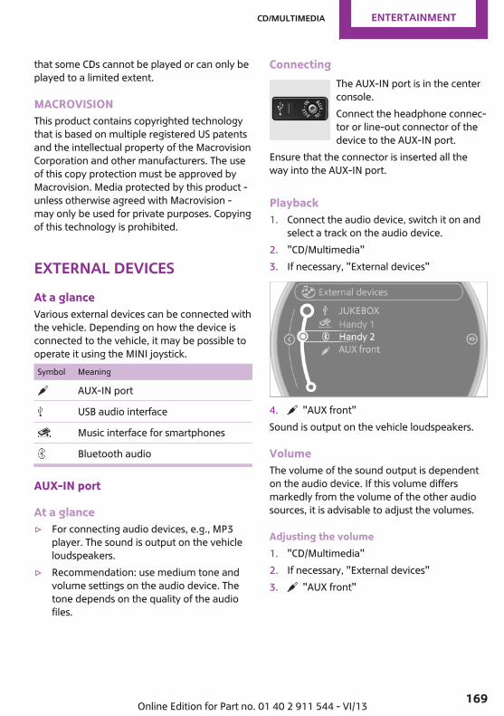
that some CDs cannot be played or can only beplayed to a limited extent.
MACROVISIONThis product contains copyrighted technologythat is based on multiple registered US patentsand the intellectual property of the MacrovisionCorporation and other manufacturers. The useof this copy protection must be approved byMacrovision. Media protected by this product -unless otherwise agreed with Macrovision -may only be used for private purposes. Copyingof this technology is prohibited.
External devicesAt a glanceVarious external devices can be connected withthe vehicle. Depending on how the device isconnected to the vehicle, it may be possible tooperate it using the MINI joystick.Symbol Meaning
AUX-IN port
USB audio interface
Music interface for smartphones
Bluetooth audio
AUX-IN port
At a glance▷ For connecting audio devices, e.g., MP3
player. The sound is output on the vehicleloudspeakers.
▷ Recommendation: use medium tone andvolume settings on the audio device. Thetone depends on the quality of the audiofiles.
ConnectingThe AUX-IN port is in the centerconsole.Connect the headphone connec‐tor or line-out connector of thedevice to the AUX-IN port.
Ensure that the connector is inserted all theway into the AUX-IN port.
Playback1. Connect the audio device, switch it on and
select a track on the audio device.2. "CD/Multimedia"3. If necessary, "External devices"
4. "AUX front"Sound is output on the vehicle loudspeakers.
VolumeThe volume of the sound output is dependenton the audio device. If this volume differsmarkedly from the volume of the other audiosources, it is advisable to adjust the volumes.
Adjusting the volume1. "CD/Multimedia"2. If necessary, "External devices"3. "AUX front"
Seite 169
CD/multimedia Entertainment
169Online Edition for Part no. 01 40 2 911 544 - VI/13

4. "Volume"
5. Turn the MINI joystick until the desired vol‐ume is set and press the MINI joystick.
USB audio interface/music interface forsmartphones
At a glanceIt is possible to connect external audio devices.They are operated via the onboard monitor.The sound is output on the vehicle loudspeak‐ers.
Connectors for external devices▷ Connection via USB audio interface: Apple
iPod/iPhone, USB devices, e.g., MP3 play‐ers, USB flash drives, or mobile phones thatare supported by the USB audio interface.
▷ Connection via snap-in adapter, whenequipped with the music interface forsmartphones: Apple iPhone or mobilephones.Playback is only possible if no audio deviceis connected to the analog AUX-IN port.
Due to the large number of different audio de‐vices available on the market, it cannot be en‐sured that every audio device/mobile phone isoperable on the vehicle.Ask your service center about suitable audiodevices/mobile phones.
Audio filesStandard audio files can be played back:▷ MP3.
▷ WMA.▷ WAV (PCM).▷ AAC, M4A.▷ Without the voice activation system: play‐
back lists: M3U▷ With the voice activation system: playback
lists: M3U, WPL, PLS
Video filesStandard video files can be played back with acompatible Apple device:▷ MPEG4▷ H.264
File systemStandard file systems for USB devices are sup‐ported. The FAT 32 format is recommended.
ConnectingThe USB audio interface is in thecenter console.
Connection of Apple iPod/iPhone via USBaudio interfaceTo connect the iPod, use the special cableadapter for the Apple iPod. Additional informa‐tion can be obtained from the service center oron the Internet: www.mini.com/connectivity.Connect the Apple iPod/iPhone with the AUX-IN port and USB interface.The Apple iPod/iPhone menu structure is sup‐ported by the USB audio interface.
Connection of a USB device via the USBaudio interfaceConnect using a flexible adapter cable to pro‐tect the USB audio interface and the USB deviceagainst physical damage.Connect the USB device to the USB interface.
Seite 170
Entertainment CD/multimedia
170 Online Edition for Part no. 01 40 2 911 544 - VI/13

After connecting for the first timeInformation on all music tracks, e.g. artist ortype of music, as well as playback lists aretransmitted into the vehicle. This may takesome time, depending on the USB device andthe number of tracks.During transmission, the tracks can be called upvia the file directory.
Number of tracksInformation from up to four USB devices or forapprox. 26,000 tracks can be stored in the ve‐hicle. If a fifth device is connected or if morethan 26,000 tracks are stored, information onexisting tracks may be deleted.
Copy protectionMusic tracks with integrated Digital Rights Man‐agement (DRM) cannot be played.
Audio playback1. "CD/Multimedia"2. "External devices"3. Select the or symbol.The playback starts with the first track.The CD cover belonging to the track may ap‐pear on the Control Display after several sec‐onds.
Track searchSelection is possible via:▷ Playback lists.▷ Information: type of music, artist, and, if
available, composer, album, track.▷ Additionally for USB devices: file directory,
composer.Tracks are displayed if they have been saved inthe Latin alphabet.
Starting the track search1. "CD/Multimedia"2. "External devices"
3. Select the or symbol.
4. "Search"5. Select the desired category, e.g., "Genre" or
"Artist".All entries are displayed in a list.▷ Open "A-Z search" and input the de‐
sired entry. When a letter is entered,the results are filtered using this letteras the first letter. If multiple letters areentered, all results that contain that se‐quence are displayed.
▷ Select the desired entry from the list.
6. Select other categories if you wish.Not all categories need to be selected. Forexample, if all of the tracks by a certain ar‐tist are to be displayed, call up that artistonly. All of the tracks by that artist are thendisplayed.
7. "Play"
Restarting a track search"New search"
Seite 171
CD/multimedia Entertainment
171Online Edition for Part no. 01 40 2 911 544 - VI/13

Playback listsCalling up playback lists.
1. "CD/Multimedia"2. "External devices"3. Select the or symbol.4. "Playlists"
Current playbackList of tracks currently being played.
1. "CD/Multimedia"2. "External devices"3. Select the or symbol.4. "Current playback"
Random playbackThe current list of tracks is played back in ran‐dom order.
1. "CD/Multimedia"2. "External devices"3. Open "Options".4. "Random"
Fast forward/reverseButtons on the steering wheel or on the CDplayer:
Press and hold the button for thecorresponding direction.
Video playback
At a glanceVideo playback is only possible with a compati‐ble iPod/iPhone. Connect using a video-capableadapter cable or, if applicable, a snap-inadapter.
PlaybackThe video image on the Control Display is dis‐played while the vehicle is stationary; in some
countries, the handbrake must be set or P mustbe engaged.
1. "CD/Multimedia"2. "External devices"3. Select the or symbol.4. "Video"
5. Select the desired file.Select the category in the file directory.
6. Press the MINI joystick.Playback of the selected video file starts.
NotesDo not expose the audio device to extreme en‐vironmental conditions, such as very high tem‐peratures; refer to the audio device operatinginstructions.Depending on the configuration of the audiofiles, e.g., bit rates greater than 256 kbit/s, thefiles may not play back correctly in each case.Audio and video playback from the snap-inadapter is only possible if no cable is connectedto the AV-IN port.
Seite 172
Entertainment CD/multimedia
172 Online Edition for Part no. 01 40 2 911 544 - VI/13
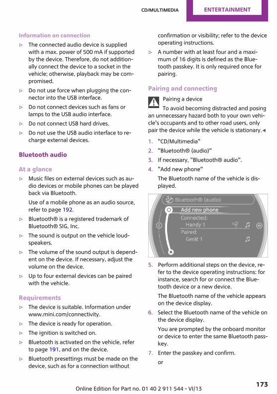
Information on connection▷ The connected audio device is supplied
with a max. power of 500 mA if supportedby the device. Therefore, do not addition‐ally connect the device to a socket in thevehicle; otherwise, playback may be com‐promised.
▷ Do not use force when plugging the con‐nector into the USB interface.
▷ Do not connect devices such as fans orlamps to the USB audio interface.
▷ Do not connect USB hard drives.▷ Do not use the USB audio interface to re‐
charge external devices.
Bluetooth audio
At a glance▷ Music files on external devices such as au‐
dio devices or mobile phones can be playedback via Bluetooth.Use of a mobile phone as an audio source,refer to page 192.
▷ Bluetooth® is a registered trademark ofBluetooth® SIG, Inc.
▷ The sound is output on the vehicle loud‐speakers.
▷ The volume of the sound output is depend‐ent on the device. If necessary, adjust thevolume on the device.
▷ Up to four external devices can be pairedwith the vehicle.
Requirements▷ The device is suitable. Information under
www.mini.com/connectivity.▷ The device is ready for operation.▷ The ignition is switched on.▷ Bluetooth is activated on the vehicle, refer
to page 191, and on the device.▷ Bluetooth presettings must be made on the
device, such as for a connection without
confirmation or visibility; refer to the deviceoperating instructions.
▷ A number with at least four and a maxi‐mum of 16 digits is defined as the Blue‐tooth passkey. It is only required once forpairing.
Pairing and connectingPairing a deviceTo avoid becoming distracted and posing
an unnecessary hazard both to your own vehi‐cle's occupants and to other road users, onlypair the device while the vehicle is stationary.◀
1. "CD/Multimedia"2. "Bluetooth® (audio)"3. If necessary, "Bluetooth® audio".4. "Add new phone"
The Bluetooth name of the vehicle is dis‐played.
5. Perform additional steps on the device, re‐fer to the device operating instructions: forinstance, search for or connect the Blue‐tooth device or a new device.The Bluetooth name of the vehicle appearson the device display.
6. Select the Bluetooth name of the vehicle onthe device display.You are prompted by the onboard monitoror device to enter the same Bluetooth pass‐key.
7. Enter the passkey and confirm.or
Seite 173
CD/multimedia Entertainment
173Online Edition for Part no. 01 40 2 911 544 - VI/13
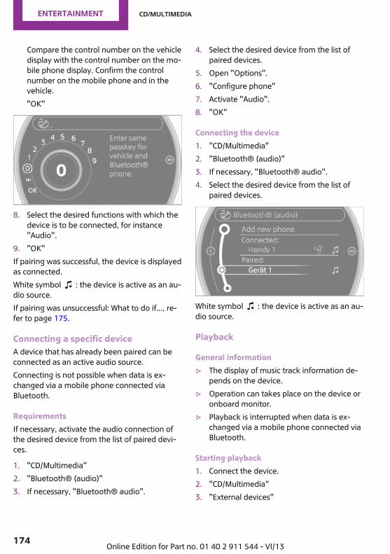
Compare the control number on the vehicledisplay with the control number on the mo‐bile phone display. Confirm the controlnumber on the mobile phone and in thevehicle."OK"
8. Select the desired functions with which thedevice is to be connected, for instance"Audio".
9. "OK"If pairing was successful, the device is displayedas connected.White symbol : the device is active as an au‐dio source.If pairing was unsuccessful: What to do if..., re‐fer to page 175.
Connecting a specific deviceA device that has already been paired can beconnected as an active audio source.Connecting is not possible when data is ex‐changed via a mobile phone connected viaBluetooth.
RequirementsIf necessary, activate the audio connection ofthe desired device from the list of paired devi‐ces.
1. "CD/Multimedia"2. "Bluetooth® (audio)"3. If necessary, "Bluetooth® audio".
4. Select the desired device from the list ofpaired devices.
5. Open "Options".6. "Configure phone"7. Activate "Audio".8. "OK"
Connecting the device1. "CD/Multimedia"2. "Bluetooth® (audio)"3. If necessary, "Bluetooth® audio".4. Select the desired device from the list of
paired devices.
White symbol : the device is active as an au‐dio source.
Playback
General information▷ The display of music track information de‐
pends on the device.▷ Operation can takes place on the device or
onboard monitor.▷ Playback is interrupted when data is ex‐
changed via a mobile phone connected viaBluetooth.
Starting playback1. Connect the device.2. "CD/Multimedia"3. "External devices"
Seite 174
Entertainment CD/multimedia
174 Online Edition for Part no. 01 40 2 911 544 - VI/13

4. Select the symbol.
5. Select the desired track from the list, if nec‐essary.
Playback menuDepending on the particular device, some ofthe functions may not be available.Symbol Function
Next trackFast forward: press and hold the sym‐bol.
Previous music trackReverse: press and hold the symbol.
Track searchMusic track search is possible depending on thedevice.
1. "CD/Multimedia"2. "External devices"3. Select the symbol.4. "Search device content"5. "A-Z search"6. Select the desired entry or directory.
Playback modeDepending on the device, different programsfor playing back music files might be available.
1. "CD/Multimedia"2. "External devices"3. Select the symbol.
4. Open "Options".5. Open "Select player".6. Select the desired channel.
Disconnecting the audio connection1. "CD/Multimedia"2. "Bluetooth® (audio)"3. Highlight the desired device.4. Open "Options".5. "Configure phone"6. "Audio"7. "OK"In the case of a mobile phone, only the audioconnection is disconnected. All other connec‐tions are retained.
Unpairing a device1. "CD/Multimedia"2. "Bluetooth® (audio)"3. If necessary, "Bluetooth® audio".4. Highlight the device that is to be unpaired.5. Open "Options".6. "Remove phone from list"
What to do if...Information on suitable devices can be found atwww.mini.com/connectivity.Suitable mobile phones, refer to page 190.The device is not supported by the vehicle.▷ Perform a software update, refer to
page 176, if needed.
Seite 175
CD/multimedia Entertainment
175Online Edition for Part no. 01 40 2 911 544 - VI/13
The device could not be paired or connected.▷ Do the Bluetooth passkeys on the device
and the vehicle match? Enter the samepasskey on the device and via the onboardmonitor.
▷ A multi-character passkey may be needed.▷ Did it take longer than 30 seconds to enter
the passkey? Repeat the pairing procedure.▷ Are too many Bluetooth devices connected
to the device or vehicle? Delete connec‐tions with other devices if necessary.
▷ Is the mobile phone in power-save mode ordoes it have only a limited remaining bat‐tery life? Charge the mobile phone in thesnap-in adapter or via a charging cable.
▷ Depending on the mobile phone, it is possi‐ble that only one device can be connectedto the vehicle. Unpair the connected devicefrom the vehicle and pair and connect onlyone device.
▷ The device no longer reacts? Switch the de‐vice off and on again.
▷ Repeat the pairing procedure.Music cannot be played back.▷ Start the program for playing back music
data on the device and select a track on thedevice if necessary.
▷ Switch the radio on and off again.Music files can only be played back softly.▷ Adjust the volume settings on the device.Videos can only be played back without audioor with delayed audio.▷ Check the compatibility of the devices. In‐
formation under www.mini.com/connectiv‐ity.
Playback is disturbed when buttons are pressedor by other messages on the device.▷ Switch off the button tones and other signal
tones on the device.
Playback is interrupted by a telephone call ortraffic bulletin and is not resumed automati‐cally.▷ Switch the radio on and off again.Playback is not possible if the mobile phone isconnected via Bluetooth Audio while it is alsoconnected via the music interface for smart‐phones in the snap-in adapter.▷ Disconnect one of the two connections; for
example, disconnect the audio connection,refer to page 175, and restart playback.
If all points in this list have been checked andthe required function is still not available,please contact the hotline or service center.
Software UpdateThe vehicle supports various external devicesdepending on the current software version.With a software update, the vehicle can supportnew mobile phones or new external device, forexample.Software updates and related current informa‐tion is available at www.mini.com/connectivity.
Displaying the current versionThe currently installed software is displayed.
1. "Settings"2. "Software update"3. "Show current version"
Updating the softwareThe software may only be updated when thevehicle is stationary.
1. Store the file for the software-update in themain director of a USB flash drive.
2. Insert the USB flash drive into the USB au‐dio interface in the center console. An up‐date via the USB interface in the glove com‐partment is not possible.
3. "Settings"4. "Software update"
Seite 176
Entertainment CD/multimedia
176 Online Edition for Part no. 01 40 2 911 544 - VI/13

5. "Update software"
6. "Start update"7. "OK"All listed software updates are installed.
Restoring the previous versionThe software version prior to the last softwareupdate can be restored.The previous version can only be restored whenthe vehicle is stationary.
1. "Settings"2. "Software update"3. "Restore previous version"4. "OK" Double-click.All listed software updates are removed.
NoteWhile the software is being updated or a previ‐ous version is being restored, MINI Connected,Office functions, and the connected devices aretemporarily unavailable. Wait several minutesfor the functions to become available again.
Seite 177
CD/multimedia Entertainment
177Online Edition for Part no. 01 40 2 911 544 - VI/13

CONNECT ME.
Online Edition for Part no. 01 40 2 911 544 - VI/13

At a glance
Controls
Driving tips
Navigation
Entertainment
Communication
Mobility
Reference
Online Edition for Part no. 01 40 2 911 544 - VI/13

Bluetooth hands-free systemVehicle equipmentThis chapter describes all series equipment aswell as country-specific and special equipmentoffered for this model series.Therefore, it alsodescribes equipment that may not be found inyour vehicle, for instance due to the selectedspecial equipment or the country version. Thisalso applies to safety-related functions and sys‐tems.
At a glanceThe conceptMobile phones can be connected with the vehi‐cle via Bluetooth.Bluetooth® is a registered trademark of Blue‐tooth® SIG, Inc.After these devices are paired once, they arerecognized automatically when the ignition isswitched on as soon as they are in the vehicleand can then be operated via the onboardmonitor, the buttons on the steering wheel,and voice activation.Up to four external devices can be paired.Certain functions may need to be enabled bythe mobile phone provider or service provider.
Using the mobile phone while drivingMake entries only when traffic and road
conditions allow. Do not hold the mobile phonein your hand while you are driving; use thehands-free system instead. If you do not ob‐serve this precaution, you can endanger the ve‐hicle occupants and other road users.◀
Approved mobile phonesDetails on which mobile phones are supportedby the hands-free system can be obtained atwww.mini.com/connectivity.
Displaying the vehicle identificationnumber and software part numberThe vehicle identification number and softwarepart number are needed to determine whichmobile phones are supported by the mobilephone preparation package. The software ver‐sion of the mobile phone may also be required.
1. "Telephone"2. Open "Options".3. "Bluetooth® info"4. "Display system information"These approved mobile phones with a certainsoftware version, support the vehicle functionsdescribed below.Malfunctions may occur with other mobilephones or software versions.Do not operate a mobile phone that is con‐nected to the vehicle on the mobile phone key‐pad, as this may lead to a malfunction.
NotesAt high temperatures, the charging function ofthe mobile phone may be limited and functionsmay not be executed.When using the mobile phone via the vehicle,note the operating instructions of the mobilephone.
Pairing/unpairing themobile phoneRequirements▷ The mobile phone is suitable, refer to
page 180.▷ The mobile phone is ready for operation.▷ Bluetooth is activated in the vehicle and on
the mobile phone.
Seite 180
Communication Bluetooth hands-free system
180 Online Edition for Part no. 01 40 2 911 544 - VI/13

▷ Bluetooth presettings may need to bemade on the mobile phone, e.g., for a con‐nection without confirmation or visibility,refer to the mobile phone operating in‐structions.
▷ Deactivate Bluetooth audio if necessary.▷ A number with at least four and a maxi‐
mum of 16 digits was defined as the Blue‐tooth passkey. It is only required once forpairing.
▷ Compare the control number on the ControlDisplay with the control number on the mo‐bile phone display. Confirm the controlnumber on the mobile phone and in thevehicle.
▷ The radio ready state is switched on.
Activating/deactivating BluetoothBluetooth is not permitted everywhere. Complywith all safety guidelines and regulations.
1. "Telephone"2. Open "Options".3. "Bluetooth®"
Pairing and connecting a mobile phonePairing the mobile phoneTo avoid becoming distracted and posing
an unnecessary hazard both to your own vehi‐cle's occupants and to other road users, only
pair the mobile phone while the vehicle is sta‐tionary.◀
1. "Telephone"2. "Bluetooth® (phone)"3. "Add new phone"
The Bluetooth name of the vehicle is dis‐played.
4. To perform additional steps on the mobilephone, refer to the mobile phone operatinginstructions: for instance, search for or con‐nect the Bluetooth device or a new device.The Bluetooth name of the vehicle appearson the mobile phone display.
5. Select the Bluetooth name of the vehicle onthe mobile phone display.
6. You are prompted by the onboard monitoror mobile phone to enter the same Blue‐tooth passkey. Enter the passkey and con‐firm.orCompare the control number on the vehicledisplay with the control number on the mo‐bile phone display. Confirm the controlnumber on the mobile phone and in thevehicle.
Seite 181
Bluetooth hands-free system Communication
181Online Edition for Part no. 01 40 2 911 544 - VI/13

"OK"
7. Select the functions for which the mobilephone is to be used.
8. "OK"9. Move the MINI joystick to the left.If the pairing was successful, the mobile phoneappears at the top of the list of mobile phones.If pairing was unsuccessful: What to do if..., re‐fer to page 182.
Following the initial pairing▷ The mobile phone is detected/connected in
the vehicle within a short period of timewhen the engine is running or the ignitionis switched on.
▷ The phone book entries of the telephonestored on the SIM card or mobile phone aretransmitted to the vehicle after detection,depending on the mobile phone.
▷ Four mobile phones can be paired.▷ Specific settings may be necessary in some
mobile phones, e.g., authorization or a se‐cure connection; refer to the mobile phoneoperating instructions.
Connecting a particular mobile phone1. "Telephone"2. "Bluetooth® (phone)"
All paired mobile phones are listed.
3. Select the mobile phone that is to be con‐nected.
Unpairing the mobile phone1. "Telephone"2. "Bluetooth® (phone)"
All paired mobile phones are listed.3. Highlight the mobile phone that is to be
unpaired.4. Open "Options".5. "Remove phone from list"
What to do if...Information on suitable mobile phones, refer topage 180.The mobile phone could not be paired or con‐nected.▷ Is Bluetooth activated in the vehicle and on
the mobile phone? Activate Bluetooth inthe vehicle and on the mobile phone.
▷ Do the Bluetooth passkeys on the mobilephone and the vehicle match? Enter thesame passkey on the mobile phone and viathe onboard monitor.
Seite 182
Communication Bluetooth hands-free system
182 Online Edition for Part no. 01 40 2 911 544 - VI/13
▷ A multi-character passkey may be needed.▷ Did it take longer than 30 seconds to enter
the passkey? Repeat the pairing procedure.▷ Are too many Bluetooth devices connected
to the mobile phone or vehicle? Delete con‐nections with other devices if necessary.
▷ The mobile phone is in power-save modeor has only a limited remaining battery life.Charge the mobile phone via the chargingcable.
▷ Depending on the mobile phone, it is possi‐ble that only one mobile phone can be con‐nected to the vehicle. Unpair the connectedmobile phone from the vehicle and pairand connect only one mobile phone.
The mobile phone no longer reacts.▷ Switch the mobile phone off and on again.▷ Is the ambient temperature too high or
low? Do not expose the mobile phone toextreme environmental conditions.
No phone book entries or only some phonebook entries are displayed, or they are incom‐plete.▷ Transmission of the phone book entries is
not yet complete.▷ It is possible that only the phone book en‐
tries of the mobile phone or the SIM cardare transmitted.
▷ It may not be possible to display phonebook entries with special characters.
▷ The number of phone book entries to bestored is too high.
▷ Is the data volume of the contact too large,e. g., due to stored information such asnotes? Reduce the data volume of the con‐tact.
The phone connection quality is poor.▷ The strength of the Bluetooth signal on the
mobile phone can be adjusted, dependingon the mobile phone.
▷ Place the mobile phone in the area of thecenter console.
If all points in this list have been checked andthe required function is still not available, con‐tact Customer Relations or the service center.
ControlsAdjusting the volume
Turn the knob until the desired volume is se‐lected. The setting is stored for the remote con‐trol currently in use.
Incoming call
Receiving callsIf the number of the caller is stored in thephone book and is transmitted by the network,the name of the contact is displayed. Other‐wise, only the phone number is displayed.If more than one phone number is assigned toa contact, only the name of the contact is dis‐played.
Accepting a callPress the button on the steeringwheel.
or "Accept"
Seite 183
Bluetooth hands-free system Communication
183Online Edition for Part no. 01 40 2 911 544 - VI/13

Rejecting a call "Reject"
Ending a callPress the button on the steeringwheel.
or
1. "Telephone"2. "End call"
Entering a phone number
Dialing a number1. "Telephone"2. "Dial number"
3. Select the digits individually.4. Select the symbol.
The phone number can also be entered byvoice.
Calls with multiple parties
General informationYou can switch between calls or connect twocalls to a single conference call. These functionsmust be supported by the mobile phone andservice provider.
Accepting a call while speaking toanother partyThis function might have to be activated by theservice provider and the mobile phone must beadjusted accordingly.If a second call comes in during an ongoing call,a call waiting signal is sounded.
"Accept"The call is accepted and the existing call is puton hold.
Establishing a second callEstablish an additional call during an active call.
1. "Telephone"2. "Active calls"3. "Hold"
Seite 184
Communication Bluetooth hands-free system
184 Online Edition for Part no. 01 40 2 911 544 - VI/13
The existing call is put on hold.
4. Dial the new phone number or select itfrom a list.
"Return"The call on hold is resumed.
Switching between two calls, hold callActive call: highlighted.Call on hold identified by: "on hold...".
Select the symbol to change to the call onhold.
Establishing a conference callTwo calls can be connected to a single tele‐phone conference call.
1. Establish two calls.2. "Conference call"
When terminating a conference call, both callsare ended. If one call is terminated by anotherparty, the other call can be continued.
DTMF suffix dialingDTMF suffix dialing can be used for gaining ac‐cess to network services or for controlling devi‐
ces, e.g., to make a remote inquiry of an an‐swering machine. The DTMF code is needed forthis purpose.
1. "Telephone"2. Select the contact from a list or "Dial
number".3. "Keypad dialing"
4. Enter the DTMF code on the onboard moni‐tor.
DTMF suffix dialing is not possible during con‐ference calls.
Phone book
DisplaysThe phone book accesses the contacts andshows all contacts for which a phone numberhas been stored. The entries can be selected tomake a call.
1. "Telephone"2. "Phone book"A symbol indicates the storage location of thecontacts.
Seite 185
Bluetooth hands-free system Communication
185Online Edition for Part no. 01 40 2 911 544 - VI/13

Calling a contact
Symbol Meaning
Contact with one stored phone num‐ber.
Contact with more than one storedphone number.
Call not possible; mobile phone with‐out reception or network.
For contacts with one stored phone number:select the required contact. The connection isbeing established.For contacts with more than one stored phonenumber: select the required contact and thephone number. The connection is being estab‐lished.
Editing a contactChanging the entries in "Contacts". When acontact is changed, the changes are not storedon the mobile phone. A copy of the entry isstored in the vehicle.
1. Highlight the contact.2. Open "Options".3. "Edit entry"The contact can be edited.
Redialing
General informationThe list of dialed numbers in the mobile phoneis transmitted to the vehicle depending on themobile phone. Possibly only those numbers aredisplayed that were dialed from the vehicle.The 20 phone numbers dialed last are dis‐played. The sorting order of the phone num‐bers depends on the particular mobile phone.
Dialing a number on the onboardmonitor1. "Telephone"2. "Redial"
3. Select the desired entry and the phonenumber if necessary.
The connection is established.
Deleting a single entry or all entriesThe deletion of entries depends on your partic‐ular mobile phone.
1. Highlight the entry.2. Open "Options".3. "Delete entry" or "Delete list"
Saving an entry in the contacts1. Highlight the entry.2. Open "Options".3. "Store as new contact" or "Add to existing
contact"4. Select the contact if necessary.5. Select the type of number: "Home",
"Business", "Mobile" or "Other"6. Complete the entries if necessary.7. "Store contact"
Received calls
Displaying callsThe list of received calls on the mobile phone istransmitted to the vehicle, depending on theparticular mobile phone. It is possible that only
Seite 186
Communication Bluetooth hands-free system
186 Online Edition for Part no. 01 40 2 911 544 - VI/13
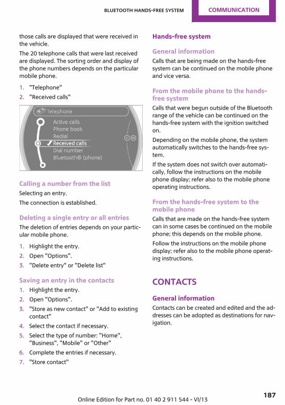
those calls are displayed that were received inthe vehicle.The 20 telephone calls that were last receivedare displayed. The sorting order and display ofthe phone numbers depends on the particularmobile phone.
1. "Telephone"2. "Received calls"
Calling a number from the listSelecting an entry.The connection is established.
Deleting a single entry or all entriesThe deletion of entries depends on your partic‐ular mobile phone.
1. Highlight the entry.2. Open "Options".3. "Delete entry" or "Delete list"
Saving an entry in the contacts1. Highlight the entry.2. Open "Options".3. "Store as new contact" or "Add to existing
contact"4. Select the contact if necessary.5. Select the type of number: "Home",
"Business", "Mobile" or "Other"6. Complete the entries if necessary.7. "Store contact"
Hands-free system
General informationCalls that are being made on the hands-freesystem can be continued on the mobile phoneand vice versa.
From the mobile phone to the hands-free systemCalls that were begun outside of the Bluetoothrange of the vehicle can be continued on thehands-free system with the ignition switchedon.Depending on the mobile phone, the systemautomatically switches to the hands-free sys‐tem.If the system does not switch over automati‐cally, follow the instructions on the mobilephone display; refer also to the mobile phoneoperating instructions.
From the hands-free system to themobile phoneCalls that are made on the hands-free systemcan in some cases be continued on the mobilephone; this depends on the mobile phone.Follow the instructions on the mobile phonedisplay; refer also to the mobile phone operat‐ing instructions.
ContactsGeneral informationContacts can be created and edited and the ad‐dresses can be adopted as destinations for nav‐igation.
Seite 187
Bluetooth hands-free system Communication
187Online Edition for Part no. 01 40 2 911 544 - VI/13
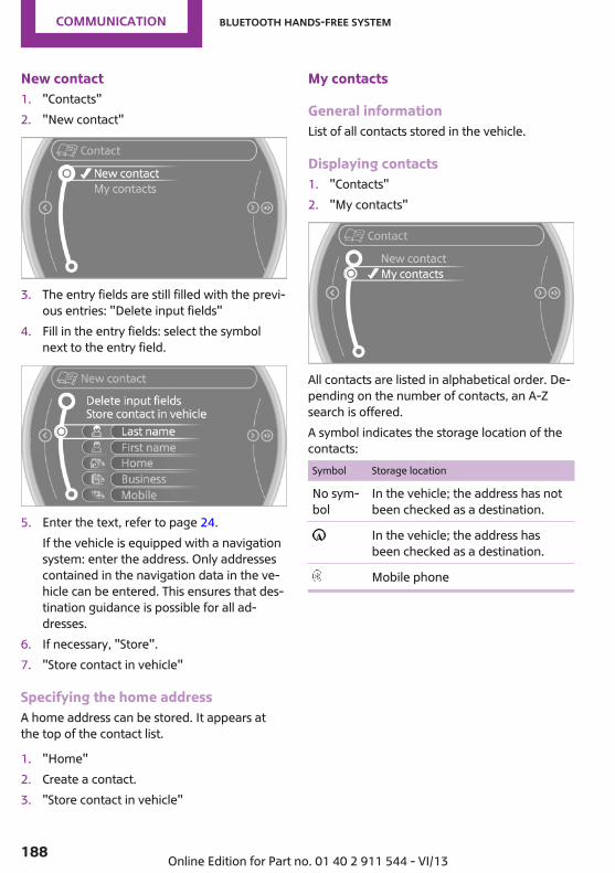
New contact1. "Contacts"2. "New contact"
3. The entry fields are still filled with the previ‐ous entries: "Delete input fields"
4. Fill in the entry fields: select the symbolnext to the entry field.
5. Enter the text, refer to page 24.If the vehicle is equipped with a navigationsystem: enter the address. Only addressescontained in the navigation data in the ve‐hicle can be entered. This ensures that des‐tination guidance is possible for all ad‐dresses.
6. If necessary, "Store".7. "Store contact in vehicle"
Specifying the home addressA home address can be stored. It appears atthe top of the contact list.
1. "Home"2. Create a contact.3. "Store contact in vehicle"
My contacts
General informationList of all contacts stored in the vehicle.
Displaying contacts1. "Contacts"2. "My contacts"
All contacts are listed in alphabetical order. De‐pending on the number of contacts, an A-Zsearch is offered.A symbol indicates the storage location of thecontacts:Symbol Storage location
No sym‐bol
In the vehicle; the address has notbeen checked as a destination.
In the vehicle; the address hasbeen checked as a destination.
Mobile phone
Seite 188
Communication Bluetooth hands-free system
188 Online Edition for Part no. 01 40 2 911 544 - VI/13

Editing a contact1. Select the desired contact.2. "Edit contact"
3. Change the entries.4. Move the MINI joystick to the left.5. "Yes"If a contact from the mobile phone is edited,the changes are not stored on the mobilephone. A copy of the entry is stored in the vehi‐cle, and only this copy is displayed. Under cer‐tain circumstances, a contact entry with thesame name is created.
Selecting the contact as a navigationdestination1. Select the desired contact.2. Select the address.3. "Start guidance" or "Add as another
destination"
Checking the address as a destinationAn address that is to be used for destinationguidance must match the navigation data con‐tained in the vehicle. The address can bechecked for this purpose.
1. Select the desired contact and highlight theaddress.
2. Open "Options".3. "Check as destination"4. Correct and store the address if necessary.
Selecting the sorting order of thenamesNames can be displayed in a different order.
1. "My contacts"2. Open "Options".3. "Display: last, first name" or "Display: first,
last name"Depending on how the contacts are stored onthe mobile phone, the sorting order of thenames may differ from the selected sorting or‐der.
Deleting contacts1. "My contacts"2. Highlight the contact.3. Open "Options".4. "Delete contact" or "Delete all contacts"
Seite 189
Bluetooth hands-free system Communication
189Online Edition for Part no. 01 40 2 911 544 - VI/13

Bluetooth mobile phonepreparation packageVehicle equipmentThis chapter describes all series equipment aswell as country-specific and special equipmentoffered for this model series.Therefore, it alsodescribes equipment that may not be found inyour vehicle, for instance due to the selectedspecial equipment or the country version. Thisalso applies to safety-related functions and sys‐tems.
At a glanceThe conceptMobile phones or other external devices suchas audio players can be connected to the vehi‐cle via Bluetooth.Bluetooth® is a registered trademark of Blue‐tooth® SIG, Inc.After these devices are paired once, they arerecognized automatically when the ignition isswitched on as soon as they are in the vehicleand can then be operated via the onboardmonitor, using the buttons on the steeringwheel, and via voice activation.Depending on their functionality, external devi‐ces can be used via the vehicle as a telephoneor as an audio source. The telephone functionsare described in the following. Operating theaudio functions, refer to page 173.Up to four external devices can be paired.Certain functions may need to be enabled bythe mobile phone provider or service provider.
Using the mobile phone while drivingMake entries only when traffic and road
conditions allow. Do not hold the mobile phonein your hand while you are driving; use the
hands-free system instead. If you do not ob‐serve this precaution, you can endanger the ve‐hicle occupants and other road users.◀
Snap-in adapterThe snap-in adapter is used to:▷ Hold the mobile phone.▷ Recharge the battery.▷ Connect the mobile phone to an outside
antenna of the vehicle.This provides for better network receptionand consistent sound quality.
Approved mobile phones
Displaying the vehicle identificationnumber and software part numberThe vehicle identification number and softwarepart number are needed to determine whichmobile phones are supported by the mobilephone preparation package. The software ver‐sion of the mobile phone may also be required.
1. "Telephone"2. Open "Options".3. "Bluetooth® info"4. "Display system information"These approved mobile phones with a certainsoftware version, support the vehicle functionsdescribed below.Malfunctions may occur with other mobilephones or software versions.Do not operate a mobile phone that is con‐nected to the vehicle on the mobile phone key‐pad, as this may lead to a malfunction.
Seite 190
Communication Bluetooth mobile phone preparation package
190 Online Edition for Part no. 01 40 2 911 544 - VI/13

NotesAt high temperatures, the charging function ofthe mobile phone may be limited and functionsmay not be executed.When using the mobile phone via the vehicle,note the operating instructions of the mobilephone.
Pairing/unpairing themobile phoneGeneral informationThe following functions are available:▷ Use of a mobile phone as a telephone.▷ Use of a mobile phone as an additional te‐
lephone.▷ Use of a mobile phone as an audio source.▷ Use of an audio device as an audio source,
refer to page 173.
Requirements▷ The mobile phone is suitable, refer to
page 190.▷ The mobile phone is ready for operation.▷ Bluetooth is activated in the vehicle and on
the mobile phone.▷ Bluetooth presettings may need to be
made on the mobile phone, e.g., for a con‐nection without confirmation or visibility,refer to the mobile phone operating in‐structions.
▷ Deactivate Bluetooth audio if necessary.▷ Compare the control number on the Control
Display with the control number on the mo‐bile phone display. Confirm the controlnumber on the mobile phone and in thevehicle.
▷ A number with at least four and a maxi‐mum of 16 digits was defined as the Blue‐
tooth passkey. It is only required once forpairing.
▷ The radio ready state is switched on.
Activating/deactivating BluetoothBluetooth is not permitted everywhere. Complywith all safety guidelines and regulations.
1. "Telephone"2. Open "Options".3. "Bluetooth®"
Additional functions
Activating/deactivating the additionalfunctionsActivate the functions before pairing to be ableto use them in the vehicle. Information on suit‐able mobile phones, refer to page 190, thatsupport this function.
1. "Telephone"2. "Bluetooth® (phone)"3. Open "Options".4. "Configure Bluetooth®"5. Select the desired additional function.
▷ "Additional telephone"▷ "Office"▷ "Bluetooth® audio"
6. "OK"An additional function cannot be assigned to atelephone while it is deactivated.
Seite 191
Bluetooth mobile phone preparation package Communication
191Online Edition for Part no. 01 40 2 911 544 - VI/13
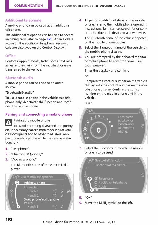
Additional telephoneA mobile phone can be used as an additionaltelephone.The additional telephone can be used to acceptincoming calls, refer to page 195. While a call isactive on the additional telephone, receivedcalls are displayed on the Control Display.
OfficeContacts, appointments, tasks, notes, text mes‐sages, and e-mails from the mobile phone aretransferred to the vehicle.
Bluetooth audioA mobile phone can be used as an audiosource."Bluetooth® audio"To use a mobile phone in the vehicle as a tele‐phone only, deactivate the function and recon‐nect the mobile phone.
Pairing and connecting a mobile phonePairing the mobile phoneTo avoid becoming distracted and posing
an unnecessary hazard both to your own vehi‐cle's occupants and to other road users, onlypair the mobile phone while the vehicle is sta‐tionary.◀
1. "Telephone"2. "Bluetooth® (phone)"3. "Add new phone"
The Bluetooth name of the vehicle is dis‐played.
4. To perform additional steps on the mobilephone, refer to the mobile phone operatinginstructions: for instance, search for or con‐nect the Bluetooth device or a new device.The Bluetooth name of the vehicle appearson the mobile phone display.
5. Select the Bluetooth name of the vehicle onthe mobile phone display.
6. You are prompted by the onboard monitoror mobile phone to enter the same Blue‐tooth passkey.Enter the passkey and confirm.orCompare the control number on the vehicledisplay with the control number on the mo‐bile phone display. Confirm the controlnumber on the mobile phone and in thevehicle."OK"
7. Select the functions for which the mobilephone is to be used.
8. "OK"9. Move the MINI joystick to the left.
Seite 192
Communication Bluetooth mobile phone preparation package
192 Online Edition for Part no. 01 40 2 911 544 - VI/13
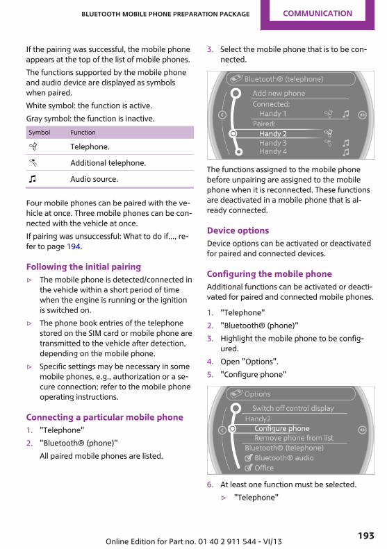
If the pairing was successful, the mobile phoneappears at the top of the list of mobile phones.The functions supported by the mobile phoneand audio device are displayed as symbolswhen paired.White symbol: the function is active.Gray symbol: the function is inactive.Symbol Function
Telephone.
Additional telephone.
Audio source.
Four mobile phones can be paired with the ve‐hicle at once. Three mobile phones can be con‐nected with the vehicle at once.If pairing was unsuccessful: What to do if..., re‐fer to page 194.
Following the initial pairing▷ The mobile phone is detected/connected in
the vehicle within a short period of timewhen the engine is running or the ignitionis switched on.
▷ The phone book entries of the telephonestored on the SIM card or mobile phone aretransmitted to the vehicle after detection,depending on the mobile phone.
▷ Specific settings may be necessary in somemobile phones, e.g., authorization or a se‐cure connection; refer to the mobile phoneoperating instructions.
Connecting a particular mobile phone1. "Telephone"2. "Bluetooth® (phone)"
All paired mobile phones are listed.
3. Select the mobile phone that is to be con‐nected.
The functions assigned to the mobile phonebefore unpairing are assigned to the mobilephone when it is reconnected. These functionsare deactivated in a mobile phone that is al‐ready connected.
Device optionsDevice options can be activated or deactivatedfor paired and connected devices.
Configuring the mobile phoneAdditional functions can be activated or deacti‐vated for paired and connected mobile phones.
1. "Telephone"2. "Bluetooth® (phone)"3. Highlight the mobile phone to be config‐
ured.4. Open "Options".5. "Configure phone"
6. At least one function must be selected.▷ "Telephone"
Seite 193
Bluetooth mobile phone preparation package Communication
193Online Edition for Part no. 01 40 2 911 544 - VI/13

▷ "Additional telephone"▷ "Audio"
7. "OK"If a function has already been assigned to an‐other connected mobile phone, the function isdeactivated in that mobile phone and the mo‐bile phone is unpaired when the function is as‐signed to a new mobile phone.
Swapping the telephone and additionaltelephoneIf a phone and additional phone are connectedto the vehicle, the function can be swapped be‐tween the two devices.
1. "Telephone"2. "Bluetooth® (phone)"3. "Swap phone/addit. phone"
Using a mobile phone as an audiosourceAn audio-capable mobile phone can be used asan audio source. Activate Bluetooth audio, referto page 192.Pair the mobile phone with the vehicle andconnect it, refer to page 192.The mobile phone is used as the audio source,provided that another device has not been con‐nected as the audio source.If another device has already been connectedas the audio source:
1. Pair the mobile phone with the vehicle andconnect it, refer to page 192.
2. "Use for audio"The mobile phone is connected as an audiosource. The previous audio source is no lon‐ger connected to the vehicle.
Unpairing a device1. "Telephone"2. "Bluetooth® (phone)"
All paired devices are listed.
3. Highlight the device that is to be unpaired.4. Open "Options".5. "Remove phone from list"
What to do if...Information on suitable mobile phones, refer topage 190.The mobile phone could not be paired or con‐nected.▷ Is Bluetooth activated in the vehicle and on
the mobile phone? Activate Bluetooth inthe vehicle and on the mobile phone.
▷ Do the Bluetooth passkeys on the mobilephone and the vehicle match? Enter thesame passkey on the mobile phone and viathe onboard monitor.
▷ A multi-character passkey may be needed.▷ Did it take longer than 30 seconds to enter
the passkey? Repeat the pairing procedure.▷ Are too many Bluetooth devices connected
to the mobile phone or vehicle? Delete con‐nections with other devices if necessary.
▷ Is the audio connection activated? Deacti‐vate the audio connection.
▷ Is the mobile phone in power-save mode ordoes it have only a limited remaining bat‐tery life? Charge the mobile phone in thesnap-in adapter or via the charging cable.
▷ Depending on the mobile phone, it is possi‐ble that only one mobile phone can be con‐nected to the vehicle. Unpair the connectedmobile phone from the vehicle and pairand connect only one mobile phone.
Seite 194
Communication Bluetooth mobile phone preparation package
194 Online Edition for Part no. 01 40 2 911 544 - VI/13

The mobile phone no longer reacts.▷ Switch the mobile phone off and on again.▷ Is the ambient temperature too high or
low? Do not expose the mobile phone toextreme environmental conditions.
The telephone functions are not available.▷ Is the mobile phone paired as an additional
telephone and is the additional telephonefunction deactivated? Activate the function.
▷ Is an outgoing call not possible? Connectthe mobile phone as a telephone.
No phone book entries or only some phonebook entries are displayed, or they are incom‐plete.▷ Transmission of the phone book entries is
not yet complete.▷ It is possible that only the phone book en‐
tries of the mobile phone or the SIM cardare transmitted.
▷ It may not be possible to display phonebook entries with special characters.
▷ The number of phone book entries to bestored is too high.
▷ Is the data volume of the contact too large,e. g., due to stored information such asnotes? Reduce the data volume of the con‐tact.
▷ Is the mobile phone connected as an audiosource or additional telephone? The mobilephone must be connected as a telephone.
The phone connection quality is poor.▷ The strength of the Bluetooth signal on the
mobile phone can be adjusted, dependingon the mobile phone.
▷ Insert the mobile phone into the snap-inadapter or place it in the area of the centerconsole.
▷ Adjust the volume of the microphone andloudspeakers separately.
If all points in this list have been checked andthe required function is still not available, con‐tact Customer Relations or the service center.
ControlsAdjusting the volume
Turn the knob until the desired volume is se‐lected. The setting is stored for the remote con‐trol currently in use.
The vehicle automatically adjusts the volume ofthe microphone on the telephone and the vol‐ume of the called party. Depending on the mo‐bile phone, the volumes may need to be ad‐justed.The settings can only be created during a calland must be adjusted separately for each tele‐phone. The settings are deleted when the tele‐phone is unpaired.
1. "Settings"2. "Tone"3. "Volume settings"4. Select the desired setting: "Microphone" or
"Loudspeak."5. To set: turn the MINI joystick.6. To save: press the MINI joystick.
Incoming call
Receiving callsIf the number of the caller is stored in thephone book and is transmitted by the network,the name of the contact is displayed. Other‐wise, only the phone number is displayed.
Seite 195
Bluetooth mobile phone preparation package Communication
195Online Edition for Part no. 01 40 2 911 544 - VI/13

If more than one phone number is assigned toa contact, only the name of the contact is dis‐played.For calls on the additional telephone, the num‐ber is only displayed if it is transmitted by thenetwork.An incoming call to one of the telephones is au‐tomatically rejected if there is an active call onthe other telephone.
Accepting a callPress the button on the steeringwheel.
or "Accept"
Rejecting a call "Reject"
The caller is redirected to the mailbox if themailbox was activated
Ending a callPress the button on the steeringwheel.
or
1. "Telephone"
2. "End call"
Entering a phone number
Dialing a number1. "Telephone"2. "Dial number"3. Select the digits individually.4. Select the symbol.
The phone number can also be entered byvoice.
Calls with multiple parties
General informationYou can switch between calls or connect twocalls to a single conference call. These functionsmust be supported by the mobile phone andservice provider.
Accepting a call while speaking toanother partyThis function might have to be activated by theservice provider and the mobile phone must beadjusted accordingly.
Seite 196
Communication Bluetooth mobile phone preparation package
196 Online Edition for Part no. 01 40 2 911 544 - VI/13

If a second call comes in during an ongoing call,a call waiting signal is sounded.
"Accept"The call is accepted and the existing call is puton hold.
Establishing a second callEstablish an additional call during an active call.
1. "Telephone"2. "Active calls"3. "Hold"
The existing call is put on hold.
4. Dial the new phone number or select itfrom a list.
"Return"The call on hold is resumed.
Switching between two calls, hold callActive call: highlighted.Call on hold identified by: "on hold...".
Select the symbol to change to the call onhold.
Establishing a conference callTwo calls can be connected to a single tele‐phone conference call.
1. Establish two calls.
2. "Conference call"
When terminating a conference call, both callsare ended. If one call is terminated by anotherparty, the other call can be continued.
Switching the microphone to muteWhen a call is active, the microphone can bemuted.
1. "Telephone"2. "Active calls"3. "Microphone mute"
A microphone that has been switched to muteis automatically reactivated:▷ When a new connection is established.▷ When switching between call parties.
DTMF suffix dialingDTMF suffix dialing can be used for gaining ac‐cess to network services or for controlling devi‐ces, e.g., to make a remote inquiry of an an‐
Seite 197
Bluetooth mobile phone preparation package Communication
197Online Edition for Part no. 01 40 2 911 544 - VI/13

swering machine. The DTMF code is needed forthis purpose.
1. "Telephone"2. Select the contact from a list or "Dial
number".3. "Keypad dialing"
4. Enter the DTMF code on the onboard moni‐tor.
DTMF suffix dialing is not possible during con‐ference calls.
Phone book
DisplaysThe phone book accesses the contacts andshows all contacts for which a phone numberhas been stored. The entries can be selected tomake a call.
1. "Telephone"2. "Phone book"A symbol indicates the storage location of thecontacts.
Calling a contact
Symbol Meaning
Contact with one stored phone num‐ber.
Contact with more than one storedphone number.
Call not possible; mobile phone with‐out reception or network.
For contacts with one stored phone number:select the required contact. The connection isbeing established.For contacts with more than one stored phonenumber: select the required contact and thephone number. The connection is being estab‐lished.
Editing a contactChanging the entries in "Contacts". When acontact is changed, the changes are not storedon the mobile phone. A copy of the entry isstored in the vehicle.
1. Highlight the contact.2. Open "Options".3. "Edit entry"The contact can be edited.
Redialing
General informationThe list of dialed numbers in the mobile phoneis transmitted to the vehicle depending on themobile phone. Possibly only those numbers aredisplayed that were dialed from the vehicle.The 20 phone numbers dialed last are dis‐played. The sorting order of the phone num‐bers depends on the particular mobile phone.
Seite 198
Communication Bluetooth mobile phone preparation package
198 Online Edition for Part no. 01 40 2 911 544 - VI/13

Dialing a number on the onboardmonitor1. "Telephone"2. "Redial"
3. Select the desired entry and the phonenumber if necessary.
The connection is established.
Deleting a single entry or all entriesThe deletion of entries depends on your partic‐ular mobile phone.
1. Highlight the entry.2. Open "Options".3. "Delete entry" or "Delete list"
Saving an entry in the contacts1. Highlight the entry.2. Open "Options".3. "Store as new contact" or "Add to existing
contact"4. Select the contact if necessary.5. Select the type of number: "Home",
"Business", "Mobile" or "Other"6. Complete the entries if necessary.7. "Store contact"
Received calls
Displaying callsThe list of received calls on the mobile phone istransmitted to the vehicle, depending on theparticular mobile phone. It is possible that only
those calls are displayed that were received inthe vehicle.The 20 telephone calls that were last receivedare displayed. The sorting order and display ofthe phone numbers depends on the particularmobile phone.
1. "Telephone"2. "Received calls"
Calling a number from the listSelecting an entry.The connection is established.
Deleting a single entry or all entriesThe deletion of entries depends on your partic‐ular mobile phone.
1. Highlight the entry.2. Open "Options".3. "Delete entry" or "Delete list"
Saving an entry in the contacts1. Highlight the entry.2. Open "Options".3. "Store as new contact" or "Add to existing
contact"4. Select the contact if necessary.5. Select the type of number: "Home",
"Business", "Mobile" or "Other"6. Complete the entries if necessary.7. "Store contact"
Seite 199
Bluetooth mobile phone preparation package Communication
199Online Edition for Part no. 01 40 2 911 544 - VI/13

Snap-in adapterGeneral informationMore information on compatible snap-inadapters that support the functions of the mo‐bile phone is available at the service center.
NotesAt high temperatures, the charging function ofthe mobile phone may be limited and functionsmay not be executed.When using the mobile phone via the vehicle,note the operating instructions of the mobilephone.
Installation positionIn the center armrest.
Inserting/removing the snap-in adapter1. Press button 1 and remove the cover.
2. Insert the snap-in adapter at the front, ar‐row 1, and press down, arrow 2, until it en‐gages.
3. To remove the snap-in adapter: press but‐ton 1.
Inserting the mobile phone1. Depending on the mobile phone, remove
the protective cap from the antenna con‐nector and from the USB connection of themobile phone.
2. With the buttons facing up, slide the mobilephone up toward the electrical contactsand press it down until it engages.
The battery is charged beginning with the radioready state of the vehicle.
Seite 200
Communication Bluetooth mobile phone preparation package
200 Online Edition for Part no. 01 40 2 911 544 - VI/13

Removing the mobile phone
Press the button and remove the mobilephone.
Seite 201
Bluetooth mobile phone preparation package Communication
201Online Edition for Part no. 01 40 2 911 544 - VI/13

OfficeVehicle equipmentThis chapter describes all series equipment aswell as country-specific and special equipmentoffered for this model series.Therefore, it alsodescribes equipment that may not be found inyour vehicle, for instance due to the selectedspecial equipment or the country version. Thisalso applies to safety-related functions and sys‐tems.
At a glanceGeneral informationContacts, appointments, tasks, notes, text mes‐sages, and e-mails from the mobile phone canbe displayed on the Control Display if the mo‐bile phone provides compatible support ofthese functions and the necessary Bluetoothstandards.Information about which mobile phones andfunctions are available can be found atwww.mini.com/connectivity.Contents are only displayed in full length whenthe vehicle is stationary.The mobile phone has read-access only.
Do not use Office while drivingTo avoid becoming distracted and posing
an unnecessary hazard to your vehicle's occu‐pants and to other road users, never attempt touse the controls or enter information unlesstraffic and road conditions allow this.◀
Requirements▷ A suitable mobile phone is paired with the
vehicle and connected. In some mobilephones, data access must be confirmed onthe mobile phone.
▷ The time, time zone, and date, refer topage 72, are correctly set on the ControlDisplay and on the mobile phone, for in‐stance to correctly display appointments.
UpdatingData are updated every time the mobile phoneis connected to the vehicle. Appointment en‐tries, tasks, notes and reminders can be up‐dated separately.
1. "Office"2. "Current office", "Calendar", "Tasks",
"Notes" or "Reminders"3. Open "Options".4. "Update data"
Mobile phone data are transmitted again tothe vehicle.
Office informationThe number of unread messages and activetasks as well as the upcoming appointmentsare displayed.
1. "Office"2. "Current office"3. Select the desired entry to display details.
Seite 202
Communication Office
202 Online Edition for Part no. 01 40 2 911 544 - VI/13

ContactsAt a glanceContacts can be created and edited. The con‐tacts from the mobile phone are displayed aswell if this function is supported by the mobilephone. The addresses can be adopted as desti‐nations for navigation and the phone numberscan be dialed.
Displaying contacts
General information1. "Office"2. "Contacts"
All contacts are listed in alphabetical order. De‐pending on the number of contacts, an A-Zsearch is offered.A symbol indicates the storage location of thecontacts.Symbol Storage location
No sym‐bol
In the vehicle; the address has notbeen checked as a destination.
In the vehicle; the address hasbeen checked as a destination.
Mobile phone.
Dialing a phone number1. Select the desired contact.2. Select the phone number.
The connection is established.
Editing a contact1. Select the desired contact.2. "Edit contact"
3. Change the entries.4. "Store contact in vehicle"When a contact is edited, the changes are notstored on the mobile phone. A copy of the en‐try is stored in the vehicle.
Selecting the contact as a navigationdestination1. Select the desired contact.2. Select the address.
When contacts from the mobile phone areused, the address may need to be matchedto the navigation data contained in the ve‐hicle. In this case:Correct the address.
3. "Start guidance" or "Add as anotherdestination"
Checking the address as a destinationAn address that is to be used for destinationguidance must match the navigation data con‐
Seite 203
Office Communication
203Online Edition for Part no. 01 40 2 911 544 - VI/13

tained in the vehicle. The address can bechecked for this purpose.
1. Select the desired contact and highlight theaddress.
2. Open "Options".3. "Check as destination"4. Correct and store the address if necessary.If the address is corrected and stored, a copy ofit is stored in the vehicle. The address is notchanged on the mobile phone.
New contact
General informationA contact can have up to 8 phone numbers,2 addresses, 3 e-mail addresses and one Inter‐net address.
1. "Office"2. "Contacts"3. Open "Options".4. "New contact"
5. The entry fields are still filled with the previ‐ous entries: "Delete input fields"
6. Fill in the entry fields: select the symbolnext to the entry field.
7. Enter the text and assign the contact type.8. If the vehicle is equipped with a navigation
system: enter the address. Only addressescontained in the navigation data in the ve‐hicle can be entered. This ensures that des‐tination guidance is possible for all ad‐dresses.
If necessary, "Accept address".9. "Store contact in vehicle"
Contact typesVarious contact types can be assigned to phonenumbers and addresses.Symbol Meaning
Home phone number.
Business phone number.
Mobile phone number.
Other phone number.
Home address.
Business address.
Specifying the home addressA home address can be stored. It appears atthe top of the contact list.
1. "Office"2. "Contacts"3. "Home"4. Create a contact.5. "Store contact in vehicle"
Selecting the sorting order of thenamesNames can be displayed in a different order.
1. "Office"2. "Contacts"3. Open "Options".4. "Display: last, first name" or "Display: first,
last name"Depending on how the contacts were stored onthe mobile phone, the sorting order of thenames may differ from the selected sorting or‐der.
Seite 204
Communication Office
204 Online Edition for Part no. 01 40 2 911 544 - VI/13

Show contact picturesPictures stored with the contacts are stored inthe vehicle when the mobile phone is con‐nected to the vehicle. The number of transmit‐ted pictures depends on the mobile phone. Themobile phone must support this function.
1. "Office"2. "Contacts"3. Open "Options".4. "Configure Bluetooth®"5. "Show images"Display of all contact pictures is activated or de‐activated.
Deleting contactsOnly contacts that are stored in the vehicle aredeleted. The contacts on the mobile phonecannot be deleted.
1. "Office"2. "Contacts"3. Highlight the contact.4. Open "Options".5. "Delete contact" or "Delete all contacts"
MessagesGeneral informationWhether or not text messages and e-mails fromthe mobile phone are displayed depends onwhether transmission from the mobile phoneto the vehicle is supported. Text messages ande-mails may not be supported by the serviceprovider, or the function may need to be ena‐bled separately. After the mobile phone is firstpaired, transmission may take several minutes.Messages are only displayed in full length whenthe vehicle is stationary. Messages from the ad‐ditional telephone are not transmitted.
Displaying messages1. "Office"2. "Messages"A symbol identifies the type of message.Symbol Message type
Text messages.
E-mail from mobile phone.
Filtering the message listThe message list can be filtered if more thanone type of message exists.
1. "Filter:"2. Select the type of message.
▷ "All"All messages are displayed.
▷ "Text message"Only text messages from the mobilephone are displayed.
▷ "E-mail"Only e-mails from the mobile phoneare displayed.
Text messages
Calling the sender of a text message1. Select the desired message.2. Select the symbol.
Saving the sender in the contacts1. Highlight the desired message.2. Open "Options".3. "Store as new contact" or "Add to existing
contact"
Using contact dataContact data from appointments, tasks, textmessages, e-mails, and notes can be stored orselected, refer to page 208.
Seite 205
Office Communication
205Online Edition for Part no. 01 40 2 911 544 - VI/13

Reading the text message out loudRead the text message out loud, refer topage 208.
Displaying e-mails1. "Office"2. "Messages"3. Select the desired e-mail.
Displaying e-mail contactsIf the sender and recipient of an e-mail aretransmitted by the mobile phone, this informa‐tion is displayed in the e-mail.
"Sender/Recipient"If the e-mail addresses are stored in the con‐tacts, the contact is displayed. Select the con‐tact to display details.If the e-mail addresses are not stored in thecontacts, only the e-mail address is displayed.
Using contact dataContact data from appointments, tasks, textmessages, e-mails, and notes can be stored orselected, refer to page 208.
Deactivating the full displayWhen an e-mail is opened in the vehicle, the e-mail is fully transmitted to the vehicle. This mayresult in charges.
1. "Office"2. "Messages"3. Open "Options".4. "Fully download e-mails"
Only a part of the e-mail from the mobilephone is loaded into the vehicle.
Reading the e-mail out loudRead the e-mail out loud, refer to page 208.
CalendarDisplay the calendarAppointments during the last 20 days and thenext 50 days can be displayed.
1. "Office"2. "Calendar"
The appointments on the current day aredisplayed.
Selecting the calendar day1. Select the date.
2. Select the desired day or date.▷ "Next day"▷ "Date:"▷ "Previous day"▷ "Today"
Display the appointment1. Select the desired appointment.2. Scroll through the appointment if neces‐
sary:▷ Turn the MINI joystick.▷ Select the symbol.
Using contact dataContact data from appointments, tasks, textmessages, e-mails, and notes can be stored orselected, refer to page 208.
Seite 206
Communication Office
206 Online Edition for Part no. 01 40 2 911 544 - VI/13

Reading the appointment out loudRead the appointment out loud, refer topage 208.
TasksDisplaying the task listDisplay tasks that are due within the next90 days.
1. "Office"2. "Tasks"
Sorting the task list1. Select the header in the task list.
2. Select the sorting criterion:▷ "Priority (!)"▷ "Subject"▷ "Due date"
Displaying the task1. Select the desired task.2. Scroll in the task if necessary:
▷ Turn the MINI joystick.▷ Select the symbol.
Using contact dataContact data from appointments, tasks, textmessages, e-mails, and notes can be stored orselected, refer to page 208.
Reading the task out loudRead the task out loud, refer to page 208.
NotesDisplaying notes1. "Office"2. "Notes"
All notes are displayed.
Displaying the note1. Select the desired note.
2. Scroll in the note if necessary:▷ Turn the MINI joystick.▷ Select the symbol.
Using contact dataContact data from appointments, tasks, textmessages, e-mails, and notes can be stored orselected, refer to page 208.
Reading the note out loudRead the note out loud, refer to page 208.
Seite 207
Office Communication
207Online Edition for Part no. 01 40 2 911 544 - VI/13

RemindersDisplaying remindersReminders of pending appointments and tasksare displayed. After an appointment or after atask is due, the reminder is no longer displayed.
1. "Office"2. "Reminders"3. Select the desired reminder.The corresponding appointment or the task aredisplayed.
Using contact dataAt a glanceContact data from appointments, tasks, textmessages, e-mails, and notes can be stored orselected.
Displaying contact or selecting phonenumber1. "Use contact data"
2. Display the contact or select the phonenumber:▷ Select the contact to display contact de‐
tails.▷ Select the phone number to establish a
connection directly.
Storing contact data1. "Use contact data"2. Highlight the phone number or e-mail ad‐
dress.3. Open "Options".4. "Add to existing contact" or "Store as new
contact"
Reading out loudText messages, e-mails, appointment entries,tasks, and notes can be read out loud.
1. Select the desired message, appointment,task, or note.
2. Select the symbol.The following options are available duringreading:▷ "Pause"
Interrupt reading. Select again to restartreading.
▷ "Back to beginning"Start reading the message again from thebeginning.
▷ Select the symbol.Go back one paragraph.
▷ Select the symbol.Skip a paragraph.
▷ To end reading, move the MINI joystick tothe left.
What to do if...Information on suitable mobile phones, refer topage 190.Appointments, tasks, notes, text messages, ore-mails from the mobile phone are not dis‐played.
Seite 208
Communication Office
208 Online Edition for Part no. 01 40 2 911 544 - VI/13
▷ The mobile phone is not capable of themissing function or is not connected cor‐rectly.
▷ The Office function is deactivated.▷ The mobile phone is connected as an addi‐
tional phone.▷ Appointments are older than 20 days or are
more than 50 days in the future.▷ The tasks have been marked as completed
or have a due date that lies more than90 days in the future.
▷ Depending on the number of stored ap‐pointments, task notes, and messages inthe mobile phone, not all are displayed inthe vehicle.
Not all appointments and tasks from the mobilephone are displayed at the right time?▷ The time zone, time, or date is incorrectly
set on the Control Display and mobilephone.
Entries are not displayed in full length.▷ Text were already transmitted from the
mobile phone in a shortened form.▷ Synchronization between the mobile phone
and vehicle may take several minutes.The contact pictures are not being displayed?▷ Up to 200 contact pictures can be stored in
the vehicle.If all points in this list have been checked andthe required function is still not available,please contact the hotline or service center.
Seite 209
Office Communication
209Online Edition for Part no. 01 40 2 911 544 - VI/13

MINI ConnectedVehicle equipmentThis chapter describes all series equipment aswell as country-specific and special equipmentoffered for this model series.Therefore, it alsodescribes equipment that may not be found inyour vehicle, for instance due to the selectedspecial equipment or the country version. Thisalso applies to safety-related functions and sys‐tems.
At a glanceThe conceptCertain software applications of a suitable mo‐bile phone can be integrated in the vehicle.These software applications are displayed onthe Control Display.They are operated via the onboard monitor.The scope of the software applications mayvary by country.
Requirements▷ The mobile phone is suitable.▷ The mobile phone operating system sup‐
ports the software applications of MINIConnected.
▷ Software applications are installed on themobile phone and ready to use.
▷ Corresponding mobile wireless contract.Any additionally incurred costs are not apart of MINI Connected.
Information about suitable mobile phones,available software applications, and their instal‐lation can be obtained at www.mini.com/connectivity or from the service center.
Create the entries.Make entries only when traffic and road
conditions allow. Otherwise, the vehicle occu‐pants and other road users may be put in dan‐ger because of the distraction from driving.For reasons of safety, some software applica‐tions are usable only while the vehicle is sta‐tionary.◀
Software applicationsUse only software applications approved
by the manufacturer of your MINI; otherwise,malfunctions may occur.◀
Connecting the mobilephoneConnection via the USB audio interface
The USB audio interface is in thecenter console.Connect the mobile phone to theUSB interface and the AV-IN portusing a special adapter cable
available from the service center.
To perform additional steps on the mobilephone, refer to the mobile phone operating in‐structions: for instance, selecting and activatingsoftware applications.
Connection via the snap-in adapterThe mobile phone can also be connected, referto page 200, via the snap-in adapter.
Operating MINI ConnectedAfter the mobile phone is successfully con‐nected with the vehicle and MINI Connected isstarted, the applications are displayed on the
Seite 210
Communication MINI Connected
210 Online Edition for Part no. 01 40 2 911 544 - VI/13

Control Display and can be operated using theMINI joystick.The volume can be set using the following con‐trols:
▷ Buttons on the steeringwheel or
▷ Volume button on the radio, refer topage 158
1. Connect the mobile phone via the snap-inadapter or via the USB audio interface.
2. Press the button. The main menu isopened.
3. "MINI Connected"
4. Select the desired software application.
Notes▷ The scope of MINI Connected that can be
displayed on the Control Display dependson the range of software applications in‐stalled on the mobile phone.
▷ The data transmission of the software ap‐plications from the mobile phone to the ve‐hicle can last some time. Some softwareapplications depend on the speed of theavailable Internet connection of the mobilephone.
▷ Some mobile phones cannot simultane‐ously use MINI Connected and the Blue‐tooth hands-free system.
If necessary, restart the software applica‐tion on the mobile phone after a phoneconversation.
▷ Audio and video playback from the snap-inadapter is only possible if no cable is con‐nected to the AV-IN port.
PlugInThe conceptSelected functions of a compatible Apple de‐vice can be displayed on the Control Display viaa video connection. They are operated usingthe MINI joystick and the button on theMINI joystick.
Functional requirement▷ Suitable iPhone or iPod: as of iPhone 3GS or
iPod with software version iOS 4.1 andhigher.
▷ The MINI Connected app is not required.Information on compatible adapters and inter‐faces can be obtained from the service center.
Activating1. Connect the Apple device.
Operation takes place via the MINI joystickwith its buttons.
2. "MINI Connected"3. "PlugIn"4. Select the connection type: "Activate via
AUX connection" or"Activate via Snap-Inadapter"
5. "Activate PlugIn"6. Use the MINI joystick to navigate among
the displayed functions and select, for ex‐ample, a desired category or track.
ControlsThe PlugIn is activated to display the graphicoutput of the connected device on the Control
Seite 211
MINI Connected Communication
211Online Edition for Part no. 01 40 2 911 544 - VI/13

Display. This changes the operating functions ofthe MINI joystick and the MINI buttons until thePlugIn is deactivated again.The operation of the PlugIn depends on the iOSversion in use, e.g., iOS 4.1.
Home button
Press the button to select the followingfunctions:▷ Press 1x: opens the display menu bar.▷ Press 2x: opens the main menu.▷ Press 1x and move the MINI joystick to the
left 1x: opens the MINI Connected menu.▷ Press 1x and move the MINI joystick to the
left 2x: opens the main menu.
Toggle button
Press the button to select the followingfunctions.▷ Press 1x: return to the next higher menu
level of the iPhones/iPods.
MINI joystick▷ Press: selection/play/pause.▷ Turn: navigate through the lists.▷ Move to the left: jump to the beginning of
the current music track or to the previousmusic track in the playback list.
▷ Move the left and hold: reverse.▷ Move to the right: jump to the next music
track in the playback list.▷ Move to the right and hold: fast forward.
DeactivatingThere are several methods of deactivating thePlugIn and returning to the MINI operatinglevel.
Via the home button▷ Press 1x: returns to activating the PlugIn.
▷ Press 2x: opens the main menu.▷ Press 1x and move the MINI joystick to the
left 1x: opens the MINI Connected menu.▷ Press 1x and move the MINI joystick to the
left 2x. Opens the main menu.
Via the audio source button
Press 1x: changes to the audio sourceselected last.
Seite 212
Communication MINI Connected
212 Online Edition for Part no. 01 40 2 911 544 - VI/13

Seite 213
MINI Connected Communication
213Online Edition for Part no. 01 40 2 911 544 - VI/13

MOVE ME.
Online Edition for Part no. 01 40 2 911 544 - VI/13

At a glance
Controls
Driving tips
Navigation
Entertainment
Communication
Mobility
Reference
Online Edition for Part no. 01 40 2 911 544 - VI/13
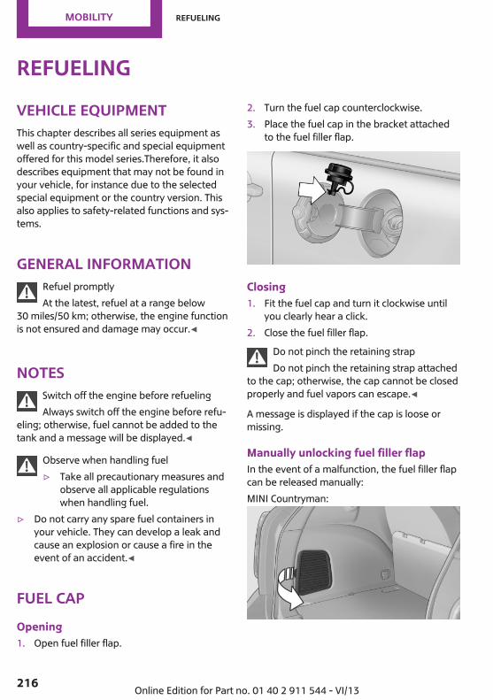
RefuelingVehicle equipmentThis chapter describes all series equipment aswell as country-specific and special equipmentoffered for this model series.Therefore, it alsodescribes equipment that may not be found inyour vehicle, for instance due to the selectedspecial equipment or the country version. Thisalso applies to safety-related functions and sys‐tems.
General informationRefuel promptlyAt the latest, refuel at a range below
30 miles/50 km; otherwise, the engine functionis not ensured and damage may occur.◀
NotesSwitch off the engine before refuelingAlways switch off the engine before refu‐
eling; otherwise, fuel cannot be added to thetank and a message will be displayed.◀
Observe when handling fuel▷ Take all precautionary measures and
observe all applicable regulationswhen handling fuel.
▷ Do not carry any spare fuel containers inyour vehicle. They can develop a leak andcause an explosion or cause a fire in theevent of an accident.◀
Fuel capOpening1. Open fuel filler flap.
2. Turn the fuel cap counterclockwise.3. Place the fuel cap in the bracket attached
to the fuel filler flap.
Closing1. Fit the fuel cap and turn it clockwise until
you clearly hear a click.2. Close the fuel filler flap.
Do not pinch the retaining strapDo not pinch the retaining strap attached
to the cap; otherwise, the cap cannot be closedproperly and fuel vapors can escape.◀
A message is displayed if the cap is loose ormissing.
Manually unlocking fuel filler flapIn the event of a malfunction, the fuel filler flapcan be released manually:MINI Countryman:
Seite 216
Mobility Refueling
216 Online Edition for Part no. 01 40 2 911 544 - VI/13

MINI Paceman:
1. Open the cargo area trim, arrow.2. Pull the green knob with the gas pump
symbol.This opens the fuel filler flap.
Observe the followingwhen refuelingWhen refueling, insert the filler nozzle com‐pletely into the filler pipe. Lifting up the fuelpump nozzle during refueling causes:▷ Premature pump shutoff.▷ Reduced efficiency in the fuel-vapor recov‐
ery system.The fuel tank is full after refueling is resumedtwice after the filler nozzle switches off for thefirst time.
Do not overfill the fuel tankDo not overfill the fuel tank; otherwise,
escaping fuel may harm the environment ordamage the vehicle.◀
Handling fuelsFollow the safety instructions provided at
gas stations; otherwise, there is a danger ofpersonal injury and property damage.◀
Fuel tank capacityApprox. 12.3 US gal/47 liters, including a re‐serve capacity of 2.1 US gal/8 liters.
Seite 217
Refueling Mobility
217Online Edition for Part no. 01 40 2 911 544 - VI/13
FuelVehicle equipmentThis chapter describes all series equipment aswell as country-specific and special equipmentoffered for this model series.Therefore, it alsodescribes equipment that may not be found inyour vehicle, for instance due to the selectedspecial equipment or the country version. Thisalso applies to safety-related functions and sys‐tems.
Fuel recommendationGasolineFor the best fuel economy, the gasoline shouldbe sulfur-free or very low in sulfur content.Do not use fuels that are labeled at the fuelpump as containing metals.
Only refuel with lead-free gasoline with‐out metal additives
Do not refuel with leaded gasoline or gasolinewith metal additives, e. g., manganese or iron;otherwise, the catalytic converter and othercomponents will be permanently damaged.◀
Fuels with a maximum ethanol content of10 %, i.e., E10, may be used for refueling.The ethanol should fulfill the following qualitystandards:US: ASTM 4806–xxCAN: CGSB-3.511–xxxx: always adhere to the currently applicablestandard.
Do not refuel with ethanol E85Do not refuel with E85, i.e., fuel with an
ethanol content of 85 %, or with Flex Fuel, asthis would damage the engine and fuel supplysystem.◀
The engine is knock controlled. Therefore, youcan refuel with different gasoline qualities.
Gasoline qualityThe manufacturer of your MINI recommends:▷ AKI 91.▷ John Cooper Works AKI 93.
Minimum fuel gradeThe manufacturer of your MINI recommendsAKI 89.
Minimum fuel gradeDo not fill up with fuel below the speci‐
fied minimum quality; otherwise, the enginemay not run properly.◀
If you use gasoline with this minimum AKI rat‐ing, the engine may produce knocking soundswhen starting at high outside temperatures.This has no effect on the engine life.
Minimum fuel gradeThe use of poor-quality fuels may result in
harmful engine deposits or damage. Addition‐ally, problems relating to drivability, startingand stalling, especially under certain environ‐mental conditions such as high ambient tem‐perature and high altitude, may occur.If drivability problems are encountered, we rec‐ommend switching to a high quality gasolinebrand and a higher octane grade — AKI num‐ber — for a few tank fills. To avoid harmful en‐gine deposits, it is highly recommended to pur‐chase gasoline from BP or Top Tier retailers.Failure to comply with these recommendationsmay result in the need for unscheduled mainte‐nance.◀
Seite 218
Mobility Fuel
218 Online Edition for Part no. 01 40 2 911 544 - VI/13

Seite 219
Fuel Mobility
219Online Edition for Part no. 01 40 2 911 544 - VI/13

Wheels and tiresVehicle equipmentThis chapter describes all series equipment aswell as country-specific and special equipmentoffered for this model series.Therefore, it alsodescribes equipment that may not be found inyour vehicle, for instance due to the selectedspecial equipment or the country version. Thisalso applies to safety-related functions and sys‐tems.
Tire inflation pressureSafety informationIt is not merely the tires' service life, but alsodriving comfort and, to a great extent, drivingsafety that depend on the condition of the tiresand the maintenance of the specified tire pres‐sure.
Checking the pressureCheck the tire inflation pressure regularlyRegularly check the tire inflation pressure
and correct it as needed: at least twice a monthand before a long trip. If you fail to observe thisprecaution, you may be driving on tires with in‐correct tire pressures, a condition that may notonly compromise your vehicle's driving stabil‐ity, but also lead to tire damage and the risk ofan accident.Do not drive with depressurized or flat tires, ex‐cept for run-flat tires. A flat tire will seriouslyimpair your vehicle's handling and braking re‐sponse. Attempts to drive on a flat tire can leadto a loss of control over the vehicle.◀
Only check the tire inflation pressure when thetires are cold. This means after a maximum of1.25 miles/2 km driving or when the vehiclehas been parked for at least 2 hours. When the
tires are warm, the tire inflation pressure ishigher.After correcting the tire inflation pressure, resetthe Tire Pressure Monitor, refer to page 88or reinitialize the Flat Tire Monitor, refer topage 86.
To check the inflation pressure, there is a valveextension behind the bumper.
Pressure specificationsThe tables below provide all the correct infla‐tion pressures for the specified tire sizes at am‐bient temperature.The inflation pressures apply to the tire sizesapproved and tire brands recommended by themanufacturer of the MINI; a list of these isavailable from the service center.For correct identification of the right tire infla‐tion pressures, observe the following:▷ Tire sizes of your vehicle▷ Maximum allowable driving speed
Tire inflation pressures for driving up to100 mph or 160 km/hFor normal driving up to 100 mph/160 km/h,adjust pressures to the respective tire inflationpressures listed on the following pages in thecolumn for traveling speeds up to 100 mph/160 km/h to achieve optimum driving comfort.These tire inflation pressures can also be foundon the driver's side door pillar when the driver'sdoor is open.
Seite 220
Mobility Wheels and tires
220 Online Edition for Part no. 01 40 2 911 544 - VI/13

MINI Countryman:
MINI Paceman:
Do not exceed the maximum permissiblespeed
The maximum permissible speed for these tirepressures is 100 mph/160 km/h. Do not exceedthis speed; otherwise, tire damage and acci‐dents may occur.◀
Tire inflation pressures for drivingabove 100 mph or 160 km/h
Adjust the tire inflation pressuresTo drive at maximum speeds in excess of
100 mph/160 km/h, adjust pressures to the re‐spective tire inflation pressures listed on thefollowing pages in the column for travelingspeeds including those exceeding 100 mph or160 km/h. Otherwise, tire damage and acci‐dents could occur.◀
Observe all national and local maximum speedlimits; otherwise, violations of the laws couldoccur.
Tire inflation pressures for MINI Countryman Cooper
Tire size Pressure specifications in bar/PSI
Traveling speeds of up to100 mph/160 km/h
Traveling speeds above100 mph/160 km/
All pressure specifications in the tableare indicated in bar/PSI with coldtires.Cold = ambient temperature
195/60 R 16 89 H M+S Std205/55 R 17 91 H M+S RSC205/55 R 17 91 H M+S A/S RSC205/55 R 17 91 V RSC225/45 R 18 91 V RSC225/40 R 19 89 V RSC
2.2/32 2.2/32 2.4/35 2.4/35
More details on the permissible load and weights, refer to page 261.
Seite 221
Wheels and tires Mobility
221Online Edition for Part no. 01 40 2 911 544 - VI/13

Tire inflation pressures for MINI Countryman Cooper S/Countryman Cooper S ALL4
Tire size Pressure specifications in bar/PSI
Traveling speeds of up to100 mph/160 km/h
Traveling speeds above100 mph/160 km/
All pressure specifications in the tableare indicated in bar/PSI with coldtires.Cold = ambient temperature
195/60 R 16 89 H M+S Std205/55 R 17 91 H M+S RSC205/55 R 17 91 H M+S A/S RSC205/55 R 17 91 V RSC225/45 R 18 91 V RSC225/40 R 19 89 V RSC
2.2/32 2.2/32 2.6/38 2.6/38
More details on the permissible load and weights, refer to page 261.
Tire inflation pressures for MINI Countryman John Cooper Works
Tire size Pressure specifications in bar/PSI
Traveling speeds of up to100 mph/160 km/h
Traveling speeds above100 mph/160 km/
All pressure specifications in the tableare indicated in bar/PSI with coldtires.Cold = ambient temperature
195/60 R 16 89 H M+S Std205/55 R 17 91 H M+S RSC205/55 R 17 91 H M+S A/S RSC225/45 R 18 91 V RSC225/40 R 19 89 V RSC
2.4/35 2.4/35 2.6/38 2.6/38
More details on the permissible load and weights, refer to page 261.
Seite 222
Mobility Wheels and tires
222 Online Edition for Part no. 01 40 2 911 544 - VI/13

Tire inflation pressures for MINI Paceman Cooper
Tire size Pressure specifications in bar/PSI
Traveling speeds of up to100 mph/160 km/h
Traveling speeds above100 mph/160 km/
All pressure specifications in the tableare indicated in bar/PSI with coldtires.Cold = ambient temperature
195/60 R 16 89 H M+S Std205/55 R 17 91 H M+S RSC205/55 R 17 91 H M+S A/S RSC205/55 R 17 91 V RSC225/45 R 18 91 V RSC225/40 R 19 89 V RSC
2.2/32 2.2/32 2.4/35 2.4/35
More details on the permissible load and weights, refer to page 262.
Tire inflation pressures for MINI Paceman Cooper S / Paceman Cooper S ALL4
Tire size Pressure specifications in bar/PSI
Traveling speeds of up to100 mph/160 km/h
Traveling speeds above100 mph/160 km/
All pressure specifications in the tableare indicated in bar/PSI with coldtires.Cold = ambient temperature
195/60 R 16 89 H M+S Std205/55 R 17 91 H M+S RSC205/55 R 17 91 H M+S A/S RSC205/55 R 17 91 V RSC225/45 R 18 91 V RSC225/40 R 19 89 V RSC
2.2/32 2.2/32 2.6/38 2.6/38
More details on the permissible load and weights, refer to page 262.
Seite 223
Wheels and tires Mobility
223Online Edition for Part no. 01 40 2 911 544 - VI/13

Tire inflation pressures for MINI Paceman John Cooper Works
Tire size Pressure specifications in bar/PSI
Traveling speeds of up to100 mph/160 km/h
Traveling speeds above100 mph/160 km/
All pressure specifications in the tableare indicated in bar/PSI with coldtires.Cold = ambient temperature
195/60 R 16 89 H M+S Std205/55 R 17 91 H M+S RSC205/55 R 17 91 H M+S A/S RSC225/45 R 18 91 V RSC225/40 R 19 89 V RSC
2.4/35 2.4/35 2.7/39 2.7/39
More details on the permissible load and weights, refer to page 262.
Tire identification marksKnowledge of the labeling on the side of thetire makes it easier to identify and choose theright tires.
Tire sizeExample: 225/45 R 17 91 V225: nominal width in mm45: aspect ratio in %R: radial tire code17: rim diameter in inches91: load rating, not for ZR tires
Speed letterQ = up to 100 mph/160 km/hT = up to 118 mph/190 km/hH = up to 131 mph/210 km/hV = up to 150 mph/240 km/hW = up to 167 mph/270 km/hY = up to 186 mph/300 km/h
Tire Identification NumberTires with DOT codes meet the guidelines ofthe U.S. Department of Transportation.DOT code:DOT xxxx xxx 1012xxxx: manufacturer code for the tire brandxxx: tire size and tire design1012: tire age
Uniform Tire Quality GradingQuality grades can be found where applicableon the tire sidewall between tread shoulderand maximum section width. For example:Treadwear 200 Traction AATemperature A
DOT Quality GradesTreadwearTraction AA A B CTemperature A B C
Seite 224
Mobility Wheels and tires
224 Online Edition for Part no. 01 40 2 911 544 - VI/13
Conform to Federal Safety RequirementsAll passenger car tires must conform to
Federal Safety Requirements in addition tothese grades.◀
TreadwearThe treadwear grade is a comparative ratingbased on the wear rate of the tire when testedunder controlled conditions on a specified gov‐ernment test course. For example, a tire graded150 would wear one and one-half (1 1/2) timesas well on the government course as a tiregraded 100. The relative performance of tiresdepends upon the actual conditions of theiruse, however, and may depart significantlyfrom the norm due to variations in driving hab‐its, service practices and differences in roadcharacteristics and climate.
TractionThe traction grades, from highest to lowest, areAA, A, B, and C.Those grades represent the tire’s ability to stopon wet pavement as measured under control‐led conditions on specified government testsurfaces of asphalt and concrete. A tire markedC may have poor traction performance.The traction grade assigned to this tire is basedon straight-ahead braking traction tests, anddoes not include acceleration, cornering, hy‐droplaning, or peak traction characteristics.
TemperatureThe temperature grades are A, the highest, B,and C, representing the tire’s resistance to thegeneration of heat and its ability to dissipateheat when tested under controlled conditionson a specified indoor laboratory test wheel.Sustained high temperature can cause the ma‐terial of the tire to degenerate and reduce tirelife, and excessive temperature can lead tosudden tire failure. The grade C corresponds toa level of performance which all passenger cartires must meet under the Federal Motor Vehi‐
cle Safety Standard No. 109. Grades B and Arepresent higher levels of performance on thelaboratory test wheel than the minimum re‐quired by law.
Temperature grade for this tireThe temperature grade for this tire is es‐
tablished for a tire that is properly inflated andnot overloaded. Excessive speed, underinfla‐tion, or excessive loading, either separately orin combination, can cause heat buildup andpossible tire failure.◀
RSC – Run-flat tiresThe symbol identifying run-flat tires is a circlewith the letters RSC on the sidewall, refer topage 228.
M+SWinter and all-season tires.These have better winter properties thansummer tires.
XLDesignation for specially reinforced tires.
Tire treadSummer tiresThe tread depth should not be less than0.12 in/3 mm, although European legislation,for example, requires a minimum tread depthof only 0.063 in/1.6 mm. At tread depths lessthan 0.12 in/3 mm, there is a great danger ofhydroplaning even in low water depths and atraised speeds.
Winter tiresThe suitability of winter tires for winter drivingis reduced noticeably when their tread depthbecomes less than 0.16 in/4 mm.
Seite 225
Wheels and tires Mobility
225Online Edition for Part no. 01 40 2 911 544 - VI/13

Minimum tread depth
Wear indicators in the tread base are distrib‐uted around the circumference of the tire andare marked on the tire sidewall with TWI, TreadWear Indicator. When the tire tread has beenworn down to the wear indicators, a tread hasreached a depth of 0.063 in/1.6 mm.
Tire damageGeneral informationInspect your tires often for damage, foreign ob‐jects lodged in the tread, and tread wear.
NotesDriving over rough or damaged road surfaces,as well as debris, curbs and other obstacles cancause serious damage to wheels, tires and sus‐pension parts. This is more likely to occur withlow-profile tires, which provide less cushioningbetween the wheel and the road. Be careful toavoid road hazards and reduce your speed, es‐pecially if your vehicle is equipped with low-profile tires.Indications of tire damage or other vehicle de‐fects:▷ Unusual vibrations during driving.▷ Unusual handling such as a strong ten‐
dency to pull to the left or right.Damage can be caused by driving over curbs,road damage and similar situations.
In case of tire damageIf there are indications of tire damage, re‐
duce your speed immediately and have thewheels and tires checked right away; other‐wise, there is the increased risk of an accident.Drive carefully to the next service center or tireshop.If necessary, have the vehicle towed.Otherwise, tire damage can present a life-threatening hazard to vehicle occupants andother road users.◀
Repair of tire damageFor safety reasons, the manufacturer of
your vehicle recommends that you do not havedamaged tires repaired; they should be re‐placed. Otherwise, damage can occur as a re‐sult.◀
Tire ageRecommendationFor several reasons, among other things be‐cause of beginning brittleness, the manufac‐turer of your MINI recommends mounting newtires at the latest after six years, regardless ofthe actual wear.
Manufacture dateThe date of manufacture of the tires is specifiedin the tire label:DOT … 2313: the tire was manufactured inweek 23 of 2013.
Seite 226
Mobility Wheels and tires
226 Online Edition for Part no. 01 40 2 911 544 - VI/13

Changing wheels andtiresMounting
Information on mounting tiresHave mounting and balancing performed
only by a service center or tire specialist.If this work is not carried out properly, there isthe danger of subsequent damage and relatedsafety hazards.◀
Wheel and tire combinationInformation on the right wheel and tire combi‐nation and rim version for your vehicle can beobtained from the service center.Incorrect wheel and tire combinations impairthe function of a variety of systems such as ABSor DSC.To maintain good handling and vehicle re‐sponse, use only tires with a single tread con‐figuration from a single manufacturer.Following tire damage, have the original wheeland tire combination remounted on the vehicleas soon as possible.
Approved wheels and tiresThe manufacturer of your vehicle recom‐
mends that you use only wheels and tires thathave been approved for your particular vehiclemodel.For example, despite having the same officialsize ratings, variations can lead to body contactand with it, the risk of severe accidents.The manufacturer of your vehicle cannot evalu‐ate non-approved wheels and tires to deter‐mine if they are suited for use, and thereforecannot ensure the operating safety of the vehi‐cle if they are mounted.◀
Wheels with electronics for TPM TirePressure MonitorWhen mounting new tires or changing fromsummer to winter tires or vice versa, only usewheels with TPM electronics; otherwise, theTire Pressure Monitor will not be able to detecta flat tire, refer to page 87. Your service centerwill be glad to advise you.
Recommended tire brands
For each tire size, the manufacturer of your ve‐hicle recommends certain tire brands. Theseare indicated by the clearly visible marking onthe tire sidewall.With proper use, these tires meet the higheststandards for safety and handling.
Retreaded tiresThe manufacturer of your vehicle does not rec‐ommend the use of retreaded tires.
Retreaded tiresPossibly substantial variations in the de‐
sign and age of the tire casing structures canlimit service life and have a negative impact onroad safety.◀
Winter tiresThe manufacturer of your vehicle recommendswinter tires for winter roads or at temperaturesbelow +45 ℉/+7 ℃.Although so-called all-season M+S tires do pro‐vide better winter traction than summer tires,they do not provide the same level of perform‐ance as winter tires.
Seite 227
Wheels and tires Mobility
227Online Edition for Part no. 01 40 2 911 544 - VI/13

Maximum speed of winter tiresIf the maximum speed of the vehicle is higherthan the permissible speed for the winter tires,then display a corresponding sign in the field ofvision. You can obtain this sign from the tirespecialist or from your service center.
Maximum speed for winter tiresDo not exceed the maximum speed for
the winter tires; otherwise, tire damage and ac‐cidents can occur.◀
Run-flat tiresWhen mounting new tires or changing fromsummer to winter tires or vice versa, use run-flat tires for your own safety. Also, a compactwheel is not available in case of a flat tire. Yourservice center will be glad to advise you.
Rotating wheels between axlesDifferent wear patterns occur on the front andrear axles, depending on the individual condi‐tions of use.To ensure even wear on the tires, the wheelscan be rotated between the axles. Your servicecenter will be glad to advise you.After changing the tires, check the tire inflationpressure and correct it if necessary.
StorageStore wheels and tires in a cool, dry place withas little exposure to light as possible.Always protect tires against all contact with oil,grease and fuels.Do not exceed the maximum tire inflation pres‐sure indicated on the side wall of the tire.
Run-flat tiresLabel
The symbol identifying run-flat tires is a circlewith the letters RSC on the sidewall.Run-flat tires are tires with special rims thatsupport themselves for a limited period of time.The sidewall reinforcement ensures that thetire can continue to be used to a limited extentif it has lost pressure and even if it has becomecompletely depressurized.For continued driving in the event of a flat tire,refer to page 86.
Correcting a flat tireSafety measures in case of a breakdown▷ Park the vehicle as far as possible
from passing traffic and on solidground. Switch on the hazard warn‐ing system.
▷ Let the steering wheel lock engage with thewheels in the straight-ahead position, setthe handbrake, and engage first gear or re‐verse, or engage selector lever position P.
▷ Have all vehicle occupants get out of thevehicle and ensure that they remain out‐side the immediate area in a safe place,such as behind a guardrail.
Seite 228
Mobility Wheels and tires
228 Online Edition for Part no. 01 40 2 911 544 - VI/13

▷ If a warning triangle or portable hazardwarning lamp is required, set it up on theroadside at an appropriate distance fromthe rear of the vehicle. Comply with allsafety guidelines and regulations.◀
The procedure to correct a flat tire depends onthe equipment in the vehicle:▷ Run-flat tires, refer to page 228.▷ MINI Mobility System, refer to page 229.
MINI Mobility SystemNotes▷ Follow the instructions on using the Mobi‐
lity System found on the compressor andsealant bottle.
▷ Use of the Mobility System may be ineffec‐tive if tire damage is greater than approx.1/8 in/4 mm in size.
▷ Contact the nearest service center if the tirecannot be made drivable.
▷ If possible, do not remove foreign bodiesthat have penetrated the tire.
▷ Pull the speed limit sticker off the sealantbottle and apply it to the steering wheel.
Sealant and compressor
1 Sealant bottle and speed limit sticker2 Filling hose
Note the use-by date on the sealant bottle.
3 Holder for the sealant bottle4 Compressor5 Connector and cable for the lighter socket/
socket in passenger compartment 109.6 Connection hose for connecting the com‐
pressor and sealant bottle or the compres‐sor and wheel
7 On/off switch8 Pressure gauge for displaying the tire infla‐
tion pressure9 Release button for reducing the tire infla‐
tion pressure
The connector, cable, and connecting hose arestowed in the compressor housing.
Using the Mobility SystemTo repair a flat tire with the Mobility System,proceed as follows:▷ Filling the tire with sealant▷ Distributing the sealant▷ Correcting the tire inflation pressure
Filling the tire with sealantAdhere to the specified sequenceAdhere to the specified sequence of the
steps; otherwise, sealant may escape underhigh pressure.◀
1. Shake the sealant bottle.2. Pull the connection hose 6 fully out of the
compressor housing and screw it onto thesealant bottle connection. Ensure that theconnection hose is not kinked.
Seite 229
Wheels and tires Mobility
229Online Edition for Part no. 01 40 2 911 544 - VI/13
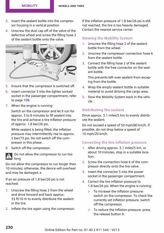
3. Insert the sealant bottle into the compres‐sor housing in a vertical position.
4. Unscrew the dust cap off of the valve of thedefective wheel and screw the filling hose 2of the sealant bottle onto the valve.
5. Ensure that the compressor is switched off.6. Insert connector 5 into the lighter socket/
socket in the passenger compartment, referto page 109.
7. When the engine is running:Switch on the compressor and let it run forapprox. 3 to 8 minutes to fill sealant intothe tire and achieve a tire inflation pressureof approx. 1.8 bar/26 psi.While sealant is being filled, the inflationpressure may intermittently rise to approx.5 bar/73 psi. Do not switch off the com‐pressor in this phase.
8. Switch off the compressor.Do not allow the compressor to run toolong
Do not allow the compressor to run longer than10 minutes; otherwise, the device will overheatand may be damaged.◀
If an air pressure of 1.8 bar/26 psi is notreached:
1. Unscrew the filling hose 2 from the wheeland drive forward and back approx.33 ft/10 m to evenly distribute the sealantin the tire.
2. Inflate the tire again using the compressor.
If the inflation pressure of 1.8 bar/26 psi is stillnot reached, the tire is too heavily damaged.Contact the nearest service center.
Stowing the Mobility System1. Unscrew the filling hose 2 of the sealant
bottle from the wheel.2. Unscrew the compressor connection hose 6
from the sealant bottle.3. Connect the filling hose 2 of the sealant
bottle with the free connector on the seal‐ant bottle.This prevents left-over sealant from escap‐ing from the bottle.
4. Wrap the empty sealant bottle in suitablematerial to avoid dirtying the cargo area.
5. Stow the Mobility System back in the vehi‐cle.
Distributing the sealantDrive approx. 3.1 miles/5 km to evenly distrib‐ute the sealant.Do not exceed a speed of 50 mph/80 km/h. Ifpossible, do not drop below a speed of10 mph/20 km/h.
Correcting the tire inflation pressure1. After driving approx. 3.1 miles/5 km, or
about 10 minutes, stop in a suitable loca‐tion.
2. Screw the connection hose 6 of the com‐pressor directly onto the tire valve.
3. Insert the connector 5 into the powersocket in the passenger compartment.
4. Correct the tire inflation pressure to1.8 bar/26 psi. When the engine is running:▷ To increase the inflation pressure:
switch on the compressor. To check thecurrently set inflation pressure, switchoff the compressor.
▷ To reduce the inflation pressure: pressthe release button 9.
Seite 230
Mobility Wheels and tires
230 Online Edition for Part no. 01 40 2 911 544 - VI/13

Do not allow the compressor to run toolong
Do not allow the compressor to run longer than10 minutes; otherwise, the device will overheatand may be damaged.◀
If the inflation pressure is not maintained, takethe vehicle on another drive, distributing thesealant, refer to page 230. Then repeat steps1 to 4 once.If the inflation pressure of 1.8 bar/26 psi is stillnot reached, the tire is too heavily damaged.Contact the nearest service center.
Continuing the tripNote the maximum speedDo not exceed the maximum speed of
50 mph/80 km/h; otherwise, accidents can oc‐cur.◀
Replace the defective tire as soon as possibleand have the wheel balanced.Have the Mobility System refilled.
Snow chainsOnly certain fine-link snow chains have beentested by MINI, classified as safe for use, andrecommended. Consult your service center formore information.Use only in pairs on the front wheels, equippedwith tires of the following size:195/60 R 16 M+SWith ALL4 all-wheel drive: only mount snowchains on the front wheels.Observe the manufacturer's instructions whenmounting snow chains. Do not exceed a speedof 30 mph or 50 km/h when using snow chains.Do not initialize the Flat Tire Monitor if snowchains are mounted; otherwise, the instrumentmight issue an incorrect reading. When drivingwith snow chains, it may be useful to tempora‐
rily deactivate DSC or activate DTC, refer topage 93.
Seite 231
Wheels and tires Mobility
231Online Edition for Part no. 01 40 2 911 544 - VI/13
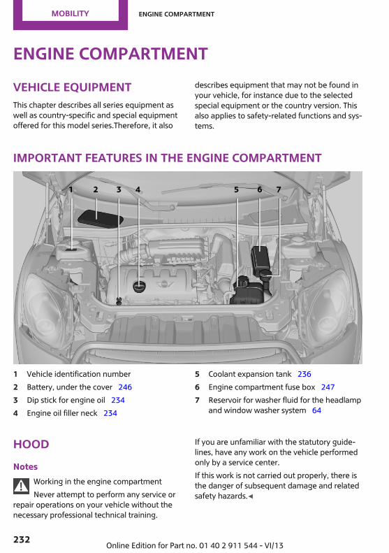
Engine compartmentVehicle equipmentThis chapter describes all series equipment aswell as country-specific and special equipmentoffered for this model series.Therefore, it also
describes equipment that may not be found inyour vehicle, for instance due to the selectedspecial equipment or the country version. Thisalso applies to safety-related functions and sys‐tems.
Important features in the engine compartment
1 Vehicle identification number2 Battery, under the cover 2463 Dip stick for engine oil 2344 Engine oil filler neck 234
5 Coolant expansion tank 2366 Engine compartment fuse box 2477 Reservoir for washer fluid for the headlamp
and window washer system 64
HoodNotes
Working in the engine compartmentNever attempt to perform any service or
repair operations on your vehicle without thenecessary professional technical training.
If you are unfamiliar with the statutory guide‐lines, have any work on the vehicle performedonly by a service center.If this work is not carried out properly, there isthe danger of subsequent damage and relatedsafety hazards.◀
Seite 232
Mobility Engine compartment
232 Online Edition for Part no. 01 40 2 911 544 - VI/13

To avoid damage, make sure that thewiper arms are resting against the wind‐
shield before you open the engine compart‐ment. Do not open the engine hood before theengine has cooled down; otherwise, injuriesmay result.◀
Unlocking and opening the hood1. Pull the lever.
2. Lift the hood all the way.3. Press the release handle and open the
hood.
Danger of injury when the hood is openThere is a danger of injury from protrud‐
ing parts when the hood is open.◀
Closing the hood
Close the hood from a height of ap‐prox. 16 in/40 cm with momentum. It must beclearly heard to engage.
Hood open when drivingIf you see any signs that the hood is not
completely closed while driving, pull over im‐mediately and close it securely.◀
Danger of pinchingMake sure that the closing path of the
hood is clear; otherwise, injuries may result.◀
Seite 233
Engine compartment Mobility
233Online Edition for Part no. 01 40 2 911 544 - VI/13

Engine oilVehicle equipmentThis chapter describes all series equipment aswell as country-specific and special equipmentoffered for this model series.Therefore, it alsodescribes equipment that may not be found inyour vehicle, for instance due to the selectedspecial equipment or the country version. Thisalso applies to safety-related functions and sys‐tems.
Engine oilGeneral informationEngine oil consumption depends on the drivingstyle and the conditions of use. A highly sportydriving style, for example, results in considera‐bly higher engine oil consumption.Therefore, regularly check the engine oil levelafter refueling.
Checking the oil level with a dip stick1. Park the vehicle on level ground when the
engine is at operating temperature, i.e., af‐ter driving continuously for at least6 2 miles/10 km.
2. Switch the engine off.3. After approx. 5 minutes, pull out the dip
stick and wipe it off with a lint-free cloth,paper towel, etc.
4. Carefully insert the dip stick all the way intothe measuring tube and pull it out again.
The oil level must be between the twomarks on the dip stick.
The oil quantity between the two marks on thedip stick equals approx. 1 US quart/1 liter.
Do not exceed the high mark.Do not exceed the high mark of the dip
stick. Overfilling oil damages the engine.◀
Adding engine oil
Filler neck
Add a maximum quantity of 1 US quart/1 literof oil only after the corresponding message ap‐pears on the Control Display or, in diesel en‐gines, after the oil level is just above the lowmark of the dip stick, refer to page 234.
Add oil promptlyAdd oil within the next 30 miles/50 km;
otherwise, engine damage could result.◀
Seite 234
Mobility Engine oil
234 Online Edition for Part no. 01 40 2 911 544 - VI/13

Too much engine oilHave the vehicle checked immediately;
otherwise, surplus oil can lead to engine dam‐age.◀
Protect childrenKeep oil, grease, etc., out of reach of chil‐
dren and heed the warnings on the containersto prevent health risks.◀
Oil types for refilling
NotesNo oil additivesDo not use oil additives as these may
cause engine damage.◀
Viscosity classes of engine oilsWhen selecting an engine oil, ensure that
the engine oil belongs to one of the SAE viscos‐ity classes 0W-40, 0W-30, 5W-40, or 5W-30, ormalfunctions or engine damage may occur.◀
The engine oil quality is critical for the life of theengine.Due to national regulations, some oil types arenot available in every country.
Approved oil types
Gasoline engine
BMW High Performance SAE 5W-30
BMW Longlife-01
BMW Longlife-01 FE
Further information on approved oil types canbe obtained from the service center.
Alternative oil typesIf the approved engine oils are not available, upto 1 US quart/1 liter of an oil with the followingspecification can be used:
Gasoline engine
API SM or a higher quality standard
Oil changeAn oil change should be carried out by the serv‐ice center only.
Seite 235
Engine oil Mobility
235Online Edition for Part no. 01 40 2 911 544 - VI/13
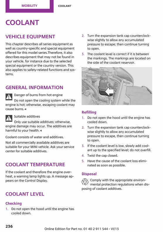
CoolantVehicle equipmentThis chapter describes all series equipment aswell as country-specific and special equipmentoffered for this model series.Therefore, it alsodescribes equipment that may not be found inyour vehicle, for instance due to the selectedspecial equipment or the country version. Thisalso applies to safety-related functions and sys‐tems.
General informationDanger of burns from hot engineDo not open the cooling system while the
engine is hot; otherwise, escaping coolant maycause burns.◀
Suitable additivesOnly use suitable additives; otherwise,
engine damage may occur. The additives areharmful to your health.◀
Coolant consists of water and additives.Not all commercially available additives aresuitable for your MINI vehicle. Ask your servicecenter for suitable additives.
Coolant temperatureIf the coolant and therefore the engine over‐heat, a warning lamp lights up. A message ap‐pears on the Control Display.
Coolant levelChecking1. Do not open the hood until the engine has
cooled down.
2. Turn the expansion tank cap counterclock‐wise slightly to allow any accumulatedpressure to escape; then continue turningto open.
3. The coolant level is correct if it is betweenthe markings. The markings are located onthe side of the coolant reservoir.
Refilling1. Do not open the hood until the engine has
cooled down.2. Turn the expansion tank cap counterclock‐
wise slightly to allow any accumulatedpressure to escape, then continue turningto open.
3. If the coolant level is low, slowly add cool‐ant up to the specified level; do not overfill.
4. Twist the cap closed.5. Have the cause of the coolant loss elimi‐
nated as soon as possible.
DisposalComply with the appropriate environ‐mental protection regulations when dis‐
posing of coolant additives.
Seite 236
Mobility Coolant
236 Online Edition for Part no. 01 40 2 911 544 - VI/13

MaintenanceVehicle equipmentThis chapter describes all series equipment aswell as country-specific and special equipmentoffered for this model series.Therefore, it alsodescribes equipment that may not be found inyour vehicle, for instance due to the selectedspecial equipment or the country version. Thisalso applies to safety-related functions and sys‐tems.
MINI maintenance system
The MINI maintenance system provides infor‐mation on required maintenance measures andthus provides support in maintaining roadsafety and the operational reliability of the ve‐hicle.
Condition Based ServiceCBSSensors and special algorithms take into ac‐count the various driving conditions of yourMINI. Based on this, Condition Based Servicedetermines the current and future mainte‐nance requirements.The system makes it possible to adapt theamount of maintenance you need to your userprofile.
Detailed information on service requirementscan be displayed on the Control Display, referto page 74.
Service data in the remote controlInformation on the required maintenance iscontinuously stored in the remote control. Yourservice center will read out this data and sug‐gest the right array of service procedures foryour vehicle. Therefore, hand your service spe‐cialist the remote control that you used mostrecently.
Setting the correct dateMake sure the date is set correctly; other‐
wise, the effectiveness of CBS Condition BasedService is not ensured.◀
Service and Warranty In‐formation Booklet forUS models and Warrantyand Service Guide Book‐let for Canadian modelsPlease consult your Service and Warranty Infor‐mation Booklet for US models and Warrantyand Service Guide Booklet for Canadian modelsfor additional information on service require‐ments.Maintenance and repair should be performedby your service center. Make sure to have regu‐lar maintenance procedures recorded in the ve‐hicle's Service and Warranty Information Book‐let for US models, and in the Warranty andService Guide Booklet for Canadian models.These entries are proof of regular maintenance.
Seite 237
Maintenance Mobility
237Online Edition for Part no. 01 40 2 911 544 - VI/13

Socket for OBD OnboardDiagnosis
Socket for Onboard DiagnosisThe socket for Onboard Diagnosis may
only be used by the service center, by work‐shops that operate according to the specifica‐tions of the vehicle manufacturer with appro‐priately trained personnel, and by otherauthorized persons. Otherwise, its use maylead to vehicle malfunctions.◀
Primary components in the vehicle emissionscan be checked via the OBD socket using a de‐vice.
EmissionsThe warning lamps light up. The vehicleis producing higher emissions. You cancontinue your journey, but moderate
your speed and exercise due caution. Have thevehicle checked as soon as possible.
Under certain circumstances, one of the lampsflashes or lights up continuously. This indicatesthat there is excessive misfiring or a malfunc‐tion in the engine. If this happens, reduce thevehicle speed and drive to the next service cen‐ter promptly. Serious engine misfiring within abrief period can seriously damage emissioncontrol components, in particular the catalyticconverter. In addition, the mechanical enginecomponents may become damaged.
If the fuel filler cap is not properly tight‐ened, the OBD system may conclude
that fuel vapor is escaping; this will cause a dis‐play to light up. If the filler cap is then tight‐ened, the display should go out in a few days.
Seite 238
Mobility Maintenance
238 Online Edition for Part no. 01 40 2 911 544 - VI/13

Replacing componentsVehicle equipmentThis chapter describes all series equipment aswell as country-specific and special equipmentoffered for this model series.Therefore, it alsodescribes equipment that may not be found inyour vehicle, for instance due to the selectedspecial equipment or the country version. Thisalso applies to safety-related functions and sys‐tems.
Wiper blade replacementGeneral information
Do not fold down the wipers withoutwiper blades
Do not fold down the wipers if wiper bladeshave not been installed; this may damage thewindshield.◀
Replacing the front wiper blades1. Fold up and hold the wiper arm.2. Squeeze the locking spring, arrows 1, and
fold out the wiper blade, arrow 2.
3. Take the wiper blade out of the catchmechanism toward the front.
4. Press the new wiper blade into the fixationuntil it engages audibly.
5. Fold down the wiper arm.
Risk of damageBefore opening the hood, ensure that the
wiper arms with wiper blades are folded ontothe window; otherwise, damage may occur.◀
Replacing the rear wiper bladeMINI Countryman:
MINI Paceman:
1. Fold up and hold the wiper arm.2. Turn the wiper blade all the way back, ar‐
row.3. Press the wiper blade against the stop to
push it out of the fixation.4. Press the new wiper blade into the fixation
until it engages audibly.5. Fold down the wiper arm.
Seite 239
Replacing components Mobility
239Online Edition for Part no. 01 40 2 911 544 - VI/13

Lamp and bulb replace‐mentNotes
Lamps and bulbsLamps and bulbs make an essential contribu‐tion to vehicle safety. Therefore, exercise cau‐tion when handling lamps and bulbs.The manufacturer of the vehicle recommendsthat you entrust corresponding procedures tothe service center if you are unfamiliar withthem or they are not described here.You can obtain a selection of replacementbulbs at the service center.
Danger of burnsOnly change bulbs when they are cool;
otherwise, there is the danger of gettingburned.◀
Working on the lighting systemWhen working on the lighting system,
you should always switch off the lights affectedto prevent short circuits.To avoid possible injury or equipment damagewhen replacing bulbs, observe any instructionsprovided by the bulb manufacturer.◀
Do not touch the bulbsDo not touch the glass of new bulbs with
your bare hands, as even minute amounts ofcontamination will burn into the bulb's surfaceand reduce its service life.Use a clean tissue, cloth or something similar,or hold the bulb by its base.◀
Caring for the headlamps, refer to page 255.For bulb replacement that is not describedhere, please contact the service center or aworkshop that works according to the repairprocedures of the manufacturer with corre‐spondingly trained personnel.
For checking and adjusting headlamp aim,please contact your MINI dealer.
Light-emitting diodes LEDsLight-emitting diodes installed behind translu‐cent lenses serve as the light source for manyof the controls and displays in the vehicle.These light-emitting diodes, which operate us‐ing a concept similar to that applied in conven‐tional lasers, are officially designated as Class 1light-emitting diodes.
Do not remove the coversDo not remove the covers, and never
stare into the unfiltered light for several hours;otherwise, irritation of the retina could result.◀
Headlamp glassCondensation can form on the inside of theheadlamps in cool or humid weather. When thelight is switched on, the condensation evapo‐rates after a short time. The headlamps do notneed to be changed.If the condensation in the headlamps does notevaporate after trips with the lights switchedon, and the amount of moisture in the head‐lamps increases, for example if water dropletsform, have them checked by your service cen‐ter.
Bi-xenon headlampsThese bulbs have a very long life and the likeli‐hood of failure is very low, provided that theyare not switched on and off excessively. If abulb should nevertheless fail, you can continuedriving cautiously with the front fog lamps, pro‐vided this is permitted by local laws.
Do not perform work/bulb replacementon xenon headlamps
Have any work on the xenon lighting system,including bulb replacement, performed only bya service center.
Seite 240
Mobility Replacing components
240 Online Edition for Part no. 01 40 2 911 544 - VI/13

Due to the high voltage present in the system,there is the danger of fatal injuries if work iscarried out improperly.◀
Front lamps, bulb replacement
Halogen low beams and high beamsBulb H13, 60/55 watt
Wear protective goggles and glovesHalogen bulbs are pressurized. Therefore,
wear protective goggles and gloves. Otherwise,there is a danger of injuries if the bulb is acci‐dentally damaged during replacement.◀
Attach the cover carefullyWhen attaching the cover, proceed care‐
fully; otherwise, leaks may occur, causing dam‐age to the headlamp system.◀
Access to the bulbs through the enginecompartmentFollow the general instructions on lamps andbulbs, refer to page 240.Low beam/high beam bulbs can be changedfrom the engine compartment.
To remove the cover:
1. Press the tab.2. Fold away the cover and take it out of the
holder.Proceed in reverse order to attach the cover.
Attach the cover carefullyWhen attaching the cover, proceed care‐
fully; otherwise, leaks may occur, causing dam‐age to the headlamp system.◀
Replacing the bulb1. Turn the bulb counterclockwise, arrow 1,
and remove it, arrow 2.
2. Press the release, arrow 1, and pull off theconnector, arrow 2.
3. Insert the new bulb and attach the cover inreverse order.
Turn signal, parking lamp, roadsideparking lamp, and front fog lamp
Access to the bulbs via the wheel housingFollow the general instructions on lamps andbulbs, refer to page 240.
Seite 241
Replacing components Mobility
241Online Edition for Part no. 01 40 2 911 544 - VI/13

1 Turn signal2 Parking lamp/roadside parking lamp/fog
lamp
Replacing the turn signal bulb21-watt bulb, P 21 W, or PY 21 W
1. Turn the wheel.2. Remove cover 1.
To do this, turn the cover counterclockwise.3. Remove the inside cover. To do this, turn
the cover counterclockwise.
4. Turn the bulb counterclockwise and re‐move it.
5. Insert the new bulb and attach the coversin reverse order.
Replacing the parking lamp bulb androadside parking lamp bulb5-watt bulb, W 5 W
1. Turn the wheel.2. Remove cover 2.
To do this, turn the cover counterclockwise.3. Turn the upper bulb counterclockwise and
remove it.
4. Insert the new bulb and attach the cover inreverse order.
Replacing the front fog lamp bulbH8 bulb, 35 watt
1. Turn the wheel.2. Remove cover 2.
To do this, turn the cover counterclockwise.3. Pull off the plug-in cable connector.4. Turn the lower bulb counterclockwise and
remove it.
5. Insert the new bulb and attach the cover inreverse order.
Seite 242
Mobility Replacing components
242 Online Edition for Part no. 01 40 2 911 544 - VI/13
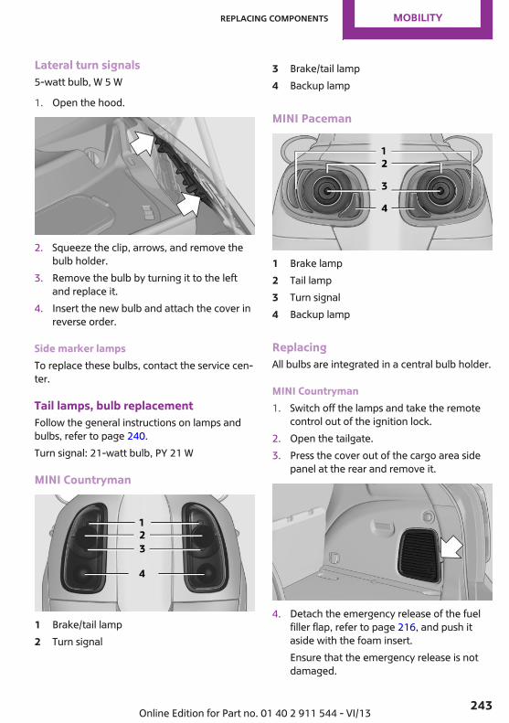
Lateral turn signals5-watt bulb, W 5 W
1. Open the hood.
2. Squeeze the clip, arrows, and remove thebulb holder.
3. Remove the bulb by turning it to the leftand replace it.
4. Insert the new bulb and attach the cover inreverse order.
Side marker lampsTo replace these bulbs, contact the service cen‐ter.
Tail lamps, bulb replacementFollow the general instructions on lamps andbulbs, refer to page 240.Turn signal: 21-watt bulb, PY 21 W
MINI Countryman
1 Brake/tail lamp2 Turn signal
3 Brake/tail lamp4 Backup lamp
MINI Paceman
1 Brake lamp2 Tail lamp3 Turn signal4 Backup lamp
ReplacingAll bulbs are integrated in a central bulb holder.
MINI Countryman1. Switch off the lamps and take the remote
control out of the ignition lock.2. Open the tailgate.3. Press the cover out of the cargo area side
panel at the rear and remove it.
4. Detach the emergency release of the fuelfiller flap, refer to page 216, and push itaside with the foam insert.Ensure that the emergency release is notdamaged.
Seite 243
Replacing components Mobility
243Online Edition for Part no. 01 40 2 911 544 - VI/13

5. Disengage the bulb holder by pushingdown the clip, arrow 1.
6. Take out the bulb holder and detach thecable, arrow 2.
7. Apply gentle pressure to the bulb whileturning it to the left and remove it.
8. Insert the new bulb and mount the bulbholder in reverse order. Ensure that thebulb holder engages in all fasteners.
9. Return the foam insert to its original posi‐tion and reattach the emergency release ofthe fuel filler flap.
10. Reattach the cover.
MINI Paceman1. Switch off the lamps and take the remote
control out of the ignition lock.2. Open the tailgate.3. Remove the cover from the cargo area side
trim.
4. Unlock the fastening elements, arrows 1, byturning.
5. Remove the screws, arrows 2, using the hexkey from the vehicle document portfolio.
6. Remove the tail lamp.7. Disengage the bulb holder by pushing
down the clip, arrows 1.
8. Take out the bulb holder and detach thecable, arrow 2.
9. Apply gentle pressure to the bulb whileturning it to the left and remove it.
10. Insert the new bulb and mount the bulbholder in reverse order. Ensure that thebulb holder engages in all fasteners.
License plate lamps5-watt bulb, C 5 W
Seite 244
Mobility Replacing components
244 Online Edition for Part no. 01 40 2 911 544 - VI/13

Replacing
MINI Countryman1. Push the lamp to the left in the catch of the
lamp housing using the screwdriver, ar‐row 1.
2. Take out the lamp, arrow 2.3. Replace the bulb.4. Insert the lamp.
MINI Paceman1. Push the lamp to the left in the catch of the
lamp housing using the screwdriver, ar‐row 1.
2. Take out the lamp, arrow 2.3. Replace the bulb.4. Insert the lamp.
Center brake lampThis lamp uses LED technology for operation. Incase of a defect, please contact your servicecenter or a workshop that works according tothe repair procedures of the manufacturer ofyour MINI with correspondingly trained person‐nel.
Changing wheelsNotesThe vehicle may be equipped with conven‐tional tires with the Mobility System, refer topage 229, or with run-flat tires, refer topage 228.No spare tire is available in the case of a flattire.Suitable tools for changing the wheels areavailable from the service center as an acces‐sory.
Jacking points for the vehicle jackMINI Countryman:
MINI Paceman:
The jacking points for the vehicle jack are lo‐cated in the positions shown.
Seite 245
Replacing components Mobility
245Online Edition for Part no. 01 40 2 911 544 - VI/13

Vehicle batteryMaintenanceThe battery is maintenance-free, i.e., the elec‐trolyte will last for the life of the battery in tem‐perate climate conditions.The service center will be happy to answer anyquestions on the battery.
Battery replacementUse approved vehicle batteriesOnly use vehicle batteries that have been
approved for your vehicle by the manufacturer;otherwise, the vehicle could be damaged andsystems or functions may not be fully availa‐ble.◀
Have the vehicle battery registered by the serv‐ice center after it is replaced to ensure that allcomfort functions are available without restric‐tions and that any associated Check Controlmessages are no longer displayed.
Charging the battery
NoteDo not connect the charger to the socketDo not connect the battery charger to the
socket installed in the vehicle at the factory asthis could damage the battery.◀
Only charge the battery in the vehicle when theengine is switched off. Connections, refer topage 248.
General informationEnsure that the battery is sufficiently charged toachieve the full battery life.It may be necessary to charge the battery inthe following cases:▷ When the vehicle is frequently used to
travel short distances.▷ When the vehicle has not been driven for
more than one month.
Power failureAfter a temporary power failure, some equip‐ment will be restricted in its use and will needto be reinitialized. In addition, certain individualsettings will be lost and must be updated:▷ Time and date: the values must be up‐
dated, refer to page 72.▷ Radio: the stations need to be stored again,
refer to page 159.▷ Onboard monitor: full functionality will be
restored after some time.▷ Glass sunroof, electrical: it may only be pos‐
sible to tilt the roof. The system needs to beinitialized. Contact the service center.
Indicator/warning lampsLights up red: the vehicle battery is nolonger being charged. Alternator mal‐function.
Switch off all unnecessary electrical consumers.Have the battery checked immediately.
Lights up yellow: the battery chargelevel is very low, the battery is old, or itis not securely connected.
Charge the battery by taking a long drive or us‐ing an external charger. If the indicators appearagain, have the battery checked as soon aspossible.
Disposing of old batteriesHave used batteries disposed of by theservice center after they are replaced ortake them to a recycling center.
Maintain the battery in an upright position fortransport and storage. Secure the battery sothat it does not tip over during transport.
Seite 246
Mobility Replacing components
246 Online Edition for Part no. 01 40 2 911 544 - VI/13

FusesReplacing fusesNever attempt to repair a blown fuse and
do not replace a defective fuse with a substi‐tute of another color or amperage rating; thiscould lead to a circuit overload, ultimately re‐sulting in a fire in the vehicle.◀
Fuses should be replaced by the service center.Information on the fuses can be found on theinside of the covers.
In the engine compartment
Opening the coverPress the snap lock.
In interior
On the right side of the footwell.
Opening the coverPush out at the recess.
Seite 247
Replacing components Mobility
247Online Edition for Part no. 01 40 2 911 544 - VI/13

Breakdown assistanceVehicle equipmentThis chapter describes all series equipment aswell as country-specific and special equipmentoffered for this model series.Therefore, it alsodescribes equipment that may not be found inyour vehicle, for instance due to the selectedspecial equipment or the country version. Thisalso applies to safety-related functions and sys‐tems.
Hazard warning flash‐ers
The button is located on the speedometer.
Warning triangle
Under the loading edge in the cargo area.To remove, open the two fasteners.
First aid kitSome of the articles contained in the first aid kithave a limited service life. Therefore, check theuse-by dates of the contents regularly and re‐place the items before they expire.
The first aid kit is located in the left side trim onthe cargo area floor or under the loading floor.
Roadside AssistanceService availabilityRoadside Assistance can be reached around theclock in many countries. You can obtain assis‐tance there in the event of a vehicle break‐down.
Jump-startingNotesIf the battery is discharged, the engine can bestarted using the battery of another vehicle andtwo jumper cables. In the same way, you canhelp jump-start another vehicle. Only usejumper cables with fully insulated clamp han‐dles.To prevent personal injury or damage to bothvehicles, adhere strictly to the following proce‐dure.
Seite 248
Mobility Breakdown assistance
248 Online Edition for Part no. 01 40 2 911 544 - VI/13

Do not touch live partsTo avoid the risk of potentially fatal injury,
always avoid all contact with electrical compo‐nents while the engine is running.◀
Preparation1. Check whether the battery of the other ve‐
hicle has a voltage of 12 volts and approxi‐mately the same capacitance in Ah. This in‐formation can be found on the battery.
2. Switch off the engine of the assisting vehi‐cle.
3. Switch off any electronic systems/powerconsumers in both vehicles.
Bodywork contact between vehiclesThere must not be any contact between
the bodies of the two vehicles, otherwise thereis a danger of shorting.◀
Connecting jumper cablesConnecting orderConnect the jumper cables in the correct
order; otherwise, there is the danger of injuryfrom sparking.◀
1. Open the battery cover in the engine com‐partment to access the positive terminal.
2. Unlock the tabs of the positive terminalcover on the left and right, arrows 1, andraise the cover, arrow 2.
3. Attach one terminal clamp of the positivejumper cable to the positive terminal of thebattery or to a starting aid terminal of thevehicle providing assistance.
4. Attach the second clamp of the positivejumper cable to the positive terminal of thebattery of the vehicle to be started.
5. Attach one terminal clamp of the negativejumper cable to the negative terminal ofthe battery, or to the corresponding engineor body ground of the vehicle providing as‐sistance.
6. Attach the second clamp of the negativejumper cable to the negative terminal of
Seite 249
Breakdown assistance Mobility
249Online Edition for Part no. 01 40 2 911 544 - VI/13
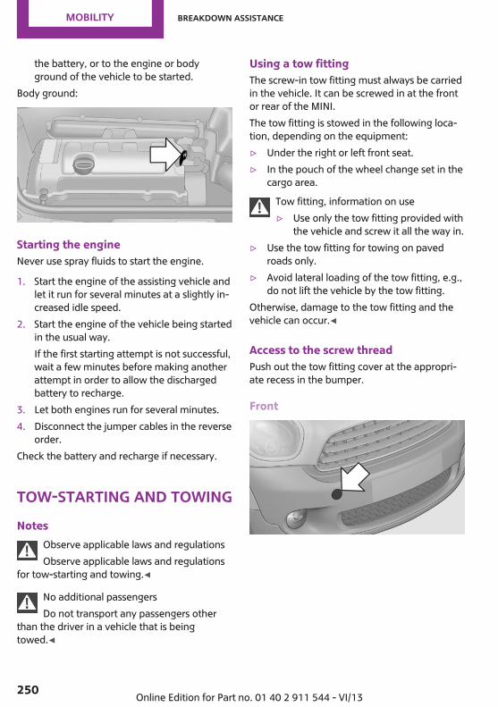
the battery, or to the engine or bodyground of the vehicle to be started.
Body ground:
Starting the engineNever use spray fluids to start the engine.
1. Start the engine of the assisting vehicle andlet it run for several minutes at a slightly in‐creased idle speed.
2. Start the engine of the vehicle being startedin the usual way.If the first starting attempt is not successful,wait a few minutes before making anotherattempt in order to allow the dischargedbattery to recharge.
3. Let both engines run for several minutes.4. Disconnect the jumper cables in the reverse
order.Check the battery and recharge if necessary.
Tow-starting and towingNotes
Observe applicable laws and regulationsObserve applicable laws and regulations
for tow-starting and towing.◀
No additional passengersDo not transport any passengers other
than the driver in a vehicle that is beingtowed.◀
Using a tow fittingThe screw-in tow fitting must always be carriedin the vehicle. It can be screwed in at the frontor rear of the MINI.The tow fitting is stowed in the following loca‐tion, depending on the equipment:▷ Under the right or left front seat.▷ In the pouch of the wheel change set in the
cargo area.Tow fitting, information on use▷ Use only the tow fitting provided with
the vehicle and screw it all the way in.▷ Use the tow fitting for towing on paved
roads only.▷ Avoid lateral loading of the tow fitting, e.g.,
do not lift the vehicle by the tow fitting.Otherwise, damage to the tow fitting and thevehicle can occur.◀
Access to the screw threadPush out the tow fitting cover at the appropri‐ate recess in the bumper.
Front
Seite 250
Mobility Breakdown assistance
250 Online Edition for Part no. 01 40 2 911 544 - VI/13

MINI Countryman: rear
MINI Paceman: rear
Being towedFollow the towing instructionsFollow all towing instructions, or vehicle
damage or accidents may occur.◀
▷ Make sure that the ignition is switched on;otherwise, the low beams, tail lamps, turnsignals, and windshield wipers may be un‐available.
▷ Do not tow the vehicle with the rear axletilted, as the front wheels could turn.
▷ When the engine is stopped, there is nopower assist. Consequently, more forceneeds to be applied when braking andsteering.
▷ Larger steering wheel movements are re‐quired.
▷ Switch on the hazard warning system, de‐pending on local regulations.
Manual transmissionGearshift lever in neutral position.
Automatic transmissionTowing vehicles with an automatic trans‐mission
Only transport vehicles with an automatictransmission on tow trucks or with raised frontwheels; otherwise, the transmission may bedamaged.◀
Towing with a tow barLight towing vehicleThe towing vehicle must not be lighter
than your vehicle, or it will not be possible tocontrol vehicle response.◀
Correctly attach the tow barOnly secure the tow bar on the tow fit‐
tings; damage can occur when it is secured onother parts of the vehicle.◀
The tow fittings used should be on the sameside on both vehicles.Should it prove impossible to avoid mountingthe tow bar at an offset angle, please observethe following:▷ Clearance and maneuvering capability will
be sharply limited during cornering.▷ The tow bar will generate lateral forces if it
is attached offset.
Towing with a tow ropeWhen starting to tow the vehicle, make surethat the tow rope is taut.To avoid jerking and the associated stresses onthe vehicle components when towing, alwaysuse nylon ropes or nylon straps.
Attaching the tow rope correctlyOnly secure the tow rope on the tow fit‐
ting; otherwise, damage can occur when it issecured on other parts of the vehicle.◀
Seite 251
Breakdown assistance Mobility
251Online Edition for Part no. 01 40 2 911 544 - VI/13
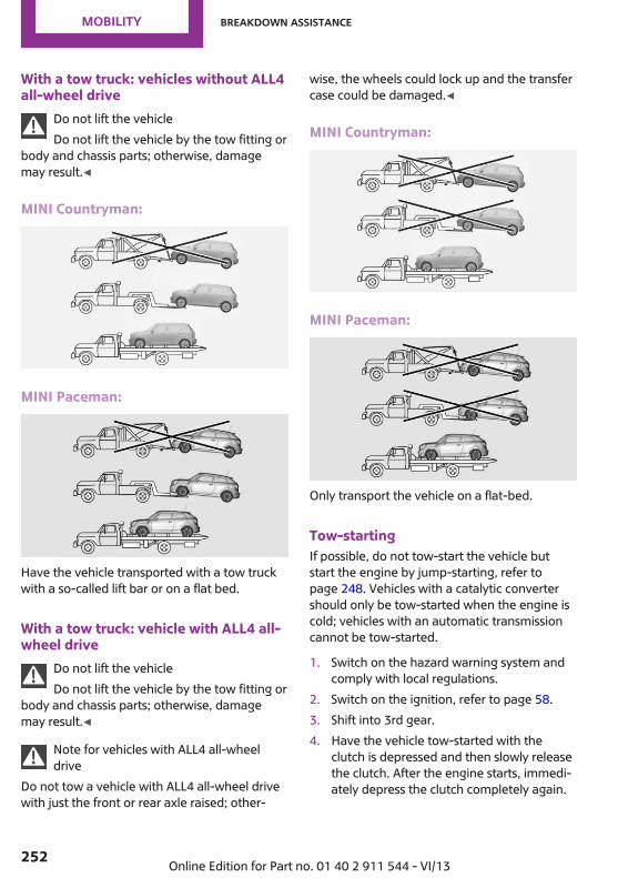
With a tow truck: vehicles without ALL4all-wheel drive
Do not lift the vehicleDo not lift the vehicle by the tow fitting or
body and chassis parts; otherwise, damagemay result.◀
MINI Countryman:
MINI Paceman:
Have the vehicle transported with a tow truckwith a so-called lift bar or on a flat bed.
With a tow truck: vehicle with ALL4 all-wheel drive
Do not lift the vehicleDo not lift the vehicle by the tow fitting or
body and chassis parts; otherwise, damagemay result.◀
Note for vehicles with ALL4 all-wheeldrive
Do not tow a vehicle with ALL4 all-wheel drivewith just the front or rear axle raised; other‐
wise, the wheels could lock up and the transfercase could be damaged.◀
MINI Countryman:
MINI Paceman:
Only transport the vehicle on a flat-bed.
Tow-startingIf possible, do not tow-start the vehicle butstart the engine by jump-starting, refer topage 248. Vehicles with a catalytic convertershould only be tow-started when the engine iscold; vehicles with an automatic transmissioncannot be tow-started.
1. Switch on the hazard warning system andcomply with local regulations.
2. Switch on the ignition, refer to page 58.3. Shift into 3rd gear.4. Have the vehicle tow-started with the
clutch is depressed and then slowly releasethe clutch. After the engine starts, immedi‐ately depress the clutch completely again.
Seite 252
Mobility Breakdown assistance
252 Online Edition for Part no. 01 40 2 911 544 - VI/13

5. Stop at a suitable location, remove the towbar or rope, and switch off the hazardwarning system.
6. Have the vehicle checked.
Seite 253
Breakdown assistance Mobility
253Online Edition for Part no. 01 40 2 911 544 - VI/13

CareVehicle equipmentThis chapter describes all series equipment aswell as country-specific and special equipmentoffered for this model series.Therefore, it alsodescribes equipment that may not be found inyour vehicle, for instance due to the selectedspecial equipment or the country version. Thisalso applies to safety-related functions and sys‐tems.
Car washesNotes
Steam jets or high-pressure washersWhen using steam jets or high-pressure
washers, hold them a sufficient distance awayand use a maximum temperature of140 ℉/60 ℃.Holding them too close or using excessivelyhigh pressures or temperatures can cause dam‐age or preliminary damage that may then leadto long-term damage.Follow the operating instructions for the high-pressure washer.◀
Do not direct steam or high-pressure washerstoward the labels applied by the manufacturer;otherwise, damage may result.
Cleaning sensors/cameras with high-pres‐sure washers
When using high-pressure washers, do notspray the seals of the retractable hardtop andthe exterior sensors and cameras, for Park Dis‐tance Control, for instance, for extended peri‐ods of time and only from a distance of at least12 in/30 cm.◀
During the winter monthsEnsure that the vehicle is washed more
frequently in winter. Intense soiling and roadsalt can damage the vehicle.◀
After washing the vehicle, apply the brakesbriefly to dry them; otherwise, braking actioncan be reduced and corrosion of the brakediscs can occur.Regularly remove foreign bodies, such asleaves, from the area of the windshield whenthe hood is open.
Washing in automatic car washesGive preference to cloth car washes or thosethat use soft brushes in order to avoid paintdamage.Do not use automatic high-pressure washers;otherwise, water may drip into the interior inthe area of the windows.Before driving into the car wash, check whetherthe system is suitable for your MINI. Note thefollowing points:▷ Vehicle dimensions, refer to page 260.▷ If necessary: fold in the exterior mirrors, re‐
fer to page 51.▷ Maximum permissible tire width.
Guide rails in car washesAvoid car washes with guide rails higher
than 4 in/10 cm; otherwise, the vehicle chassiscould be damaged.◀
Preparations before driving into the car wash:▷ Unscrew the road antenna.▷ Deactivate the rain sensor to avoid unin‐
tentional wiper activation.▷ Deactivate the rear window wiper and pro‐
tect it from damage. Ask the car wash oper‐ator about any necessary protective meas‐ures.
Seite 254
Mobility Care
254 Online Edition for Part no. 01 40 2 911 544 - VI/13

▷ Remove additional attachments, for in‐stance a spoiler or telephone antenna, ifthere is a risk that these may be damaged.
▷ Insert the remote control into the ignitionlock.
Automatic transmissionBefore driving into the car wash, note the fol‐lowing to ensure that the vehicle can roll:
1. Insert the remote control into the ignitionlock, even with Comfort Access.
2. Move the selector lever to position N.3. Release the handbrake.4. Switch the engine off.5. Leave the remote control in the ignition
lock so that the vehicle can roll.
Hand car washIf washing the vehicle by hand, use copiousquantities of water and car shampoo if neces‐sary. Clean the vehicle with a sponge or awashing brush by applying gentle pressure.Before cleaning the windshield, deactivate therain sensor to avoid unintentional wiper activa‐tion or switch off the ignition.
Adhere to the local regulations regardingwashing cars by hand.
HeadlampsDo not rub dry and do not use abrasive or caus‐tic cleansers. Soak areas that have been soiled,e.g., due to insects, with shampoo and rinse offwith copious quantities of water.Thaw ice with a window deicer; do not use anice scraper.
WindowsClean the outside and inside surfaces of thewindows and the mirror glasses with windowcleaner.
Do not clean mirror glass with cleaners contain‐ing quartz.
Wiper bladesClean with soapy water and replace regularly toavoid streaking.Wax and preservative residue and soiling onthe windows cause streaking during windowwiping and lead to premature wear on thewiper blades and malfunctions of the rain sen‐sor.
Vehicle careCar care productsRegular cleaning and care contributes signifi‐cantly to vehicle value retention.The manufacturer recommends using cleaningand care products from MINI, since these havebeen tested and approved.Original MINI CareProducts have been testedon materials, in the laboratory, and in the field,and offer optimum care and protection for MINIvehicles.
Do not use cleansers that contain alcoholor solvents
Do not use cleansers that contain alcohol orsolvents, such as lacquer thinners, heavy-dutygrease removers, fuel, or such; this could leadto surface damage.◀
Car care and cleaning productsFollow the instructions on the container.
When cleaning the interior, open the doors orwindows.Only use products intended for cleaning vehi‐cles.Cleansers can contain substances that are dan‐gerous and harmful to your health.◀
Seite 255
Care Mobility
255Online Edition for Part no. 01 40 2 911 544 - VI/13

Vehicle paintRegular care contributes to vehicle value reten‐tion and protects the paintwork against thelong-term effects of paint-damaging substan‐ces.Environmental influences in areas with higherair pollution or natural contaminants, such astree resin or pollen, can have an impact on thevehicle paint. Therefore, it is important to tailorthe frequency and extent of your car care tothese influences.Immediately remove especially aggressive sub‐stances, such as spilled fuel, oil, grease, or birddroppings, to prevent damage to the paint‐work.
Correcting paint damageDepending on the severity of the damage, re‐pair stone impact damage or scratches imme‐diately to prevent rust formation.The manufacturer recommends having paintdamage corrected with a professional repairpaint job according to factory specifications us‐ing original MINI paint materials.
PreservationPreservation is needed when water no longerbeads off of the clean paint surfaces. Only usepaint preservation products that contain car‐nauba or synthetic waxes.
Leather careThe leather processed by the manufacturer is ahigh quality natural product. Light graininess isa typical feature of natural leather.Particles of dust and road grime chafe in poresand folds, and lead to increased wear and pre‐mature degradation of the leather surface.Therefore, remove dust from the leather regu‐larly, using a cloth or vacuum cleaner.Make especially sure that light-colored leatheris cleaned regularly as it is more susceptible tosoiling.
Twice a year, treat the leather with a leather lo‐tion as dirt and grease will attack the protectivelayer of the leather.
Upholstery material careVacuum regularly with a vacuum cleaner to re‐move superficial soiling.In case of heavy soiling, e.g., beverage stains,use a soft sponge or lint-free microfiber cloth incombination with a suitable interior cleaner.Follow the instructions on the container.Clean the upholstery material down to theseams using large sweeping motions. Avoidrubbing the material vigorously.
Damage from Velcro® fastenersOpen Velcro® fasteners on pants or other
articles of clothing can damage the seat covers.Ensure that any Velcro® fasteners are closed.◀
Caring for special components
Interior plastic partsThese include:▷ Imitation leather surfaces▷ Lamp lenses▷ Indicator covers▷ Matte componentsClean with water and a solvent-free plasticcleaner if necessary.
Do not use cleansers that contain alcoholor solvents
Do not use cleansers that contain alcohol orsolvents, such as lacquer thinners, heavy-dutygrease removers, fuel, or such; this could leadto surface damage.◀
Rubber sealsOnly treat with water or a rubber care product.When cleaning rubber seals, do not use siliconesprays or other care products containing sili‐cone; otherwise, noise and damage may result.
Seite 256
Mobility Care
256 Online Edition for Part no. 01 40 2 911 544 - VI/13

Chrome surfacesCarefully clean components such as the radia‐tor grille or door handles with an ample supplyof water, possibly with shampoo added, partic‐ularly when they have been exposed to roadsalt. For additional treatment, use a chromepolish.
Light-alloy wheelsWhen cleaning the wheels on the vehicle, onlyuse a neutral wheel rim cleaner with a pH valueof 5 to 9.Do not use abrasive cleaners or a steam jet hot‐ter than 140 ℉/60 ℃; otherwise, damage mayresult. Adhere to the manufacturer instructions.Aggressive, acidic, or alkaline cleaners may de‐stroy the protective coating of neighboringcomponents such as the brake disc.
Exterior sensorsThe sensors on the outside of the vehicle, suchas for Park Distance Control, must be kept cleanand free of ice to ensure that they remain fullyfunctional.
Decorative trimClean decorative trims and fine wood compo‐nents with a moist cloth only. Then dry with asoft cloth.
Safety beltsDirty belt straps impede the reeling action andthus have a negative impact on safety.
No chemical cleaningDo not clean chemically; this can destroy
the webbing.◀
Carpets/floor matsNo objects in the area around the pedalsKeep floor mats, carpets, and any other
objects out of the area of motion of the pedals;otherwise, the function of the pedals could beimpeded while driving
Do not place additional floor mats over existingmats or other objects.Only use floor mats that have been approvedfor the vehicle and can be properly fixed inplace.Ensure that the floor mats are securely fastenedagain when they are returned after being re‐moved, such as for cleaning.◀
Floor mats can be removed for cleaning.If they are very dirty, clean with a microfibercloth and water or an interior cleaner. To pre‐vent matting of the carpet, rub back and forthin the direction of travel only.
DisplaysTo clean the displays, such as the radio or dis‐play elements, use an antistatic microfibercloth.
Cleaning displaysDo not use chemical or household cleans‐
ers.Keep all fluids and moisture away from theunit.Otherwise, they could affect or damage surfa‐ces or electrical components.Avoid pressing too hard when cleaning and donot use abrasive materials; otherwise, damagecan result.◀
CD/DVD drivesNo cleaning CDDo not use cleaning CDs; otherwise, parts
of the drive may become damaged.◀
Long-term vehicle storageYour service center can advise you on what toconsider when storing the vehicle for longerthan three months.
Seite 257
Care Mobility
257Online Edition for Part no. 01 40 2 911 544 - VI/13

FIND ME.
Online Edition for Part no. 01 40 2 911 544 - VI/13

At a glance
Controls
Driving tips
Navigation
Entertainment
Communication
Mobility
Reference
Online Edition for Part no. 01 40 2 911 544 - VI/13
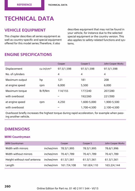
Technical dataVehicle equipmentThis chapter describes all series equipment aswell as country-specific and special equipmentoffered for this model series.Therefore, it also
describes equipment that may not be found inyour vehicle, for instance due to the selectedspecial equipment or the country version. Thisalso applies to safety-related functions and sys‐tems.
Engine specifications
Cooper Cooper S John Cooper Works
Displacement cu in/cm³ 97.5/1,598 97.5/1,598 97.5/1,598
No. of cylinders 4 4 4
Maximum output hp 121 181 208
at engine speed rpm 6,000 5,500 6,000
Maximum torque lb ft/Nm 114/155 177/240 207/280
with overboost – 192/260 221/300
at engine speed rpm 4,250 1,600-5,000 1,900-5,500
with overboost – 1,700-4,500 2,100-4,500
Overboost briefly increases the highest torque during rapid acceleration, for example when pass‐ing another vehicle.
DimensionsMINI Countryman
MINI Countryman Cooper Cooper S John Cooper Works
Width with mirrors inches/mm 78.5/1,995 78.5/1,995 78.6/1,996
Width without mirrors inches/mm 70.4/1,789 70.4/1,789 70.4/1,789
Height without roof antenna inches/mm 61.5/1,561 61.5/1,561 61.5/1,561
Length inches/mm 161.7/4,108 161.8/4,110 163.2/4,144
Seite 260
Reference Technical data
260 Online Edition for Part no. 01 40 2 911 544 - VI/13

MINI Countryman Cooper Cooper S John Cooper Works
Wheelbase inches/mm 102.2/2,595 102.2/2,595 102.2/2,596
Smallest turning circle dia. ft/m 38.1/11.6 38.1/11.6 38.1/11.6
MINI Paceman
MINI Paceman Cooper Cooper S John Cooper Works
Width with mirrors inches/mm 78.6/1,996 78.6/1,996 78.6/1,996
Width without mirrors inches/mm 70.3/1,786 70.3/1,786 70.3/1,786
Height without roof antenna inches/mm 59.8/1,518 59.9/1,522 60.1/1,527
Length inches/mm 162.2/4,120 162.2/4,120 162.8/4,134
Wheelbase inches/mm 102.2/2,596 102.2/2,596 102.2/2,596
Smallest turning circle dia. ft/m 38.1/11.6 38.1/11.6 38.1/11.6
WeightsNever exceed either the approved axle loads orthe gross vehicle weight.
MINI Countryman
Cooper Cooper S
Curb weight, road ready, with maximum special equipment
Manual transmission lbs/kg 2,954/1,340 3,053/1,385
Automatic transmission lbs/kg 3,020/1,370 3,097/1,405
Approved gross vehicle weight
Manual transmission lbs/kg 3,858/1,750 3,990/1,810
Automatic transmission lbs/kg 3,924/1,780 4,034/1,830
Load lbs/kg 860/390 860/390
Approved front axle load
Manual transmission lbs/kg 2,050/930 2,127/965
Automatic transmission lbs/kg 2,116/960 2,172/985
Approved rear axle load lbs/kg 1,918/870 1,918/870
Seite 261
Technical data Reference
261Online Edition for Part no. 01 40 2 911 544 - VI/13

Cooper Cooper S
Approved roof load capacity lbs/kg 165/75 165/75
Cargo area capacity cu ft/liter 12.4–41.3/ 350–1,170 12.4–41.3/ 350–1,170
Cooper S ALL4 John Cooper Works
Curb weight, road ready, with maximum special equipment
Manual transmission lbs/kg 3,208/1,455 3,263/1,480
Automatic transmission lbs/kg 3,252/1,475 3,307/1,500
Approved gross vehicle weight
Manual transmission lbs/kg 4,101/1,860 4,156/1,885
Automatic transmission lbs/kg 4,145/1,880 4,200/1,905
Load lbs/kg 860/390 860/390
Approved front axle load
Manual transmission lbs/kg 2,183/990 2,183/990
Automatic transmission lbs/kg 2,227/1,010 2,227/1,010
Approved rear axle load lbs/kg 2,017/915 2,072/940
Approved roof load capacity lbs/kg 165/75 165/75
Cargo area capacity cu ft/liter 12.4–41.3/ 350–1,170 12.4–41.3/ 350–1,170
MINI Paceman
Cooper Cooper S Cooper S ALL4 John Cooper Works
Curb weight, road ready, with maximum special equipment
Manual transmission lbs/kg 2,940/1,334 3,070/1,393 3,210/1,456 3,260/1,479
Automatic transmis‐sion
lbs/kg 3,010/1,365 3,110/1,411 3,260/1,479 3,310/1,501
Approved gross vehicle weight
Manual transmission lbs/kg 3,850/1,746 3,960/1,796 4,100/1,860 4,150/1,882
Automatic transmis‐sion
lbs/kg 3,920/1,778 4,010/1,819 4,140/1,878 4,200/1,905
Load lbs/kg 850/386 850/386 850/386 850/386
Seite 262
Reference Technical data
262 Online Edition for Part no. 01 40 2 911 544 - VI/13

Cooper Cooper S Cooper S ALL4 John Cooper Works
Approved front axle load
Manual transmission lbs/kg 2,050/930 2,120/962 2,180/989 2,200/998
Automatic transmis‐sion
lbs/kg 2,120/962 2,170/984 2,220/1,007 2,240/1,016
Approved rear axleload
lbs/kg 1,910/866 1,910/866 2,020/916 2,060/934
Approved roof load ca‐pacity
lbs/kg 165/75 165/75 165/75 165/75
Cargo area capacity cu ft/liter
11.6–38.1/330–1,080
11.6–38.1/330–1,080
11.6–38.1/330–1,080
11.6–38.1/330–1,080
Capacities
Notes
Fuel tank US gal/liters Approx. 12.4/approx. 47
Fuel quality, refer topage 218
Including reserve of US gal/liters Approx. 2.1/approx. 8
Seite 263
Technical data Reference
263Online Edition for Part no. 01 40 2 911 544 - VI/13

Short commands for voiceactivation systemVehicle equipmentThis chapter describes all series equipment aswell as country-specific and special equipmentoffered for this model series.Therefore, it alsodescribes equipment that may not be found inyour vehicle, for instance due to the selectedspecial equipment or the country version. Thisalso applies to safety-related functions and sys‐tems.
General informationInstructions for voice activation system, refer topage 26.
To have the available spoken instructions readout loud: ›Voice commands‹The following short commands apply to vehi‐cles equipped with a voice activation system.They have no function in vehicles in which onlythe mobile phone is operated using the voice.
AdjustingVehicle
Function Command
Opens the main menu. ›Main menu‹
Open the options. ›Options‹
Open the settings. ›Settings‹
Settings on the Control Display. ›Control display‹
Open the time and date. ›Time and date‹
Open the language and units. ›Language and units‹
Open the speed limit. ›Speed‹
Open the light. ›Lighting‹
Open the door lock. ›Door locks‹
Seite 264
Reference Short commands for voice activation system
264 Online Edition for Part no. 01 40 2 911 544 - VI/13

Vehicle informationComputer
Function Command
Open the computer. ›Onboard info‹
Open the trip computer. ›Trip computer‹
Vehicle
Function Command
Open the vehicle information. ›Vehicle info‹
Open the vehicle status. ›Vehicle status‹
NavigationGeneral information
Function Command
Navigation menu. ›Navigation‹
Open the destination entry. ›Enter address‹
Enter the address. ›Enter address‹
Enter the town/city. ›City‹
Enter the country. ›State‹
Enter the postal code. ›Postal Code‹
Open destination guidance. ›Guidance‹
Start destination guidance. ›Start guidance‹
Terminate destination guidance. ›Stop guidance‹
Open the home address. ›Home address‹
Open the route criteria. ›Route preference‹
Open the route. ›Route information‹
Switch on the spoken instruction. ›Switch on voice instructions‹
Repeat the spoken instruction. ›Repeat voice instructions‹
Seite 265
Short commands for voice activation system Reference
265Online Edition for Part no. 01 40 2 911 544 - VI/13
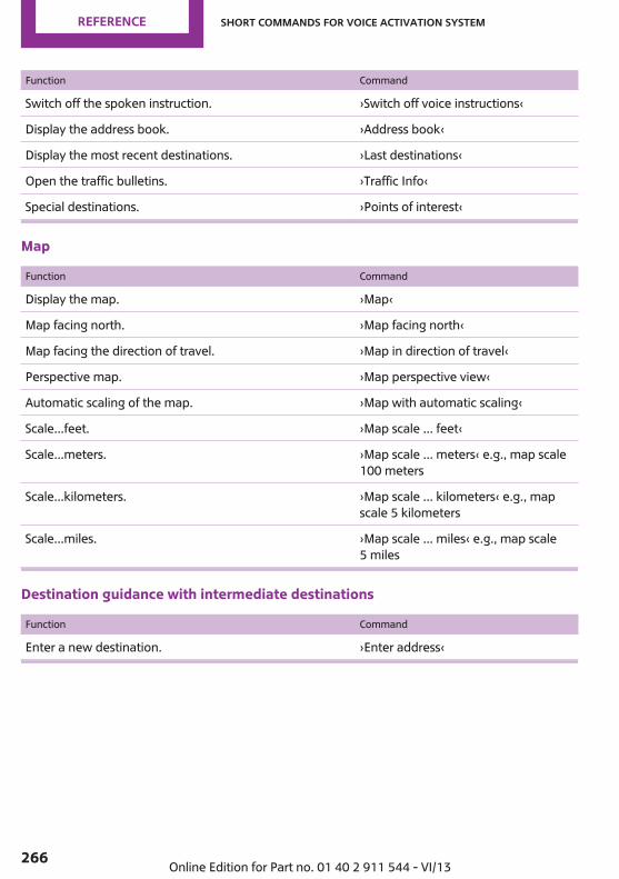
Function Command
Switch off the spoken instruction. ›Switch off voice instructions‹
Display the address book. ›Address book‹
Display the most recent destinations. ›Last destinations‹
Open the traffic bulletins. ›Traffic Info‹
Special destinations. ›Points of interest‹
Map
Function Command
Display the map. ›Map‹
Map facing north. ›Map facing north‹
Map facing the direction of travel. ›Map in direction of travel‹
Perspective map. ›Map perspective view‹
Automatic scaling of the map. ›Map with automatic scaling‹
Scale...feet. ›Map scale ... feet‹
Scale...meters. ›Map scale ... meters‹ e.g., map scale100 meters
Scale...kilometers. ›Map scale ... kilometers‹ e.g., mapscale 5 kilometers
Scale...miles. ›Map scale ... miles‹ e.g., map scale5 miles
Destination guidance with intermediate destinations
Function Command
Enter a new destination. ›Enter address‹
Seite 266
Reference Short commands for voice activation system
266 Online Edition for Part no. 01 40 2 911 544 - VI/13

RadioFM
Function Command
Open a frequency. ›Frequency ... megahertz‹ e.g.,93.5 megahertz or frequency 93.5
Open the radio. ›Radio‹
Open the FM stations. ›F M‹
Open the manual search. ›Manual‹
Select a frequency range. ›Select frequency‹
Open a station. ›Select station‹
AM
Function Command
Open a frequency. ›Frequency ... Kilohertz‹ e.g., fre‐quency 753 or 753 kilohertz
Open the AM stations. ›A M‹
Open the manual search. ›Manual‹
Satellite radio
Function Command
Open the satellite radio. ›Satellite radio‹
Switch on the satellite radio. ›Satellite radio on‹
Select a satellite radio channel. ›Select satellite radio‹ e.g., satelliteradio channel 2
Stored stations
Function Command
Open the stored stations. ›Presets‹
Choose a stored station. ›Select preset‹
Select a stored station. ›Preset ...‹ e.g., stored station 2
Seite 267
Short commands for voice activation system Reference
267Online Edition for Part no. 01 40 2 911 544 - VI/13
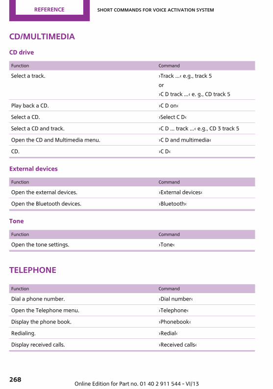
CD/multimediaCD drive
Function Command
Select a track. ›Track ...‹ e.g., track 5or›C D track ...‹ e. g., CD track 5
Play back a CD. ›C D on‹
Select a CD. ›Select C D‹
Select a CD and track. ›C D ... track ...‹ e.g., CD 3 track 5
Open the CD and Multimedia menu. ›C D and multimedia‹
CD. ›C D‹
External devices
Function Command
Open the external devices. ›External devices‹
Open the Bluetooth devices. ›Bluetooth‹
Tone
Function Command
Open the tone settings. ›Tone‹
Telephone
Function Command
Dial a phone number. ›Dial number‹
Open the Telephone menu. ›Telephone‹
Display the phone book. ›Phonebook‹
Redialing. ›Redial‹
Display received calls. ›Received calls‹
Seite 268
Reference Short commands for voice activation system
268 Online Edition for Part no. 01 40 2 911 544 - VI/13
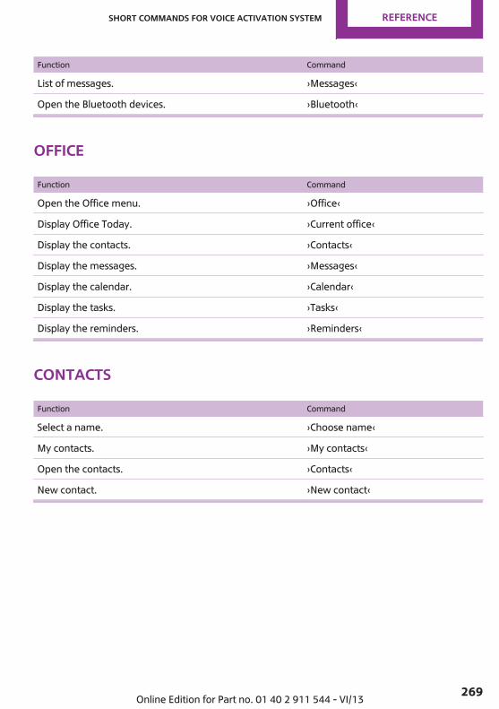
Function Command
List of messages. ›Messages‹
Open the Bluetooth devices. ›Bluetooth‹
Office
Function Command
Open the Office menu. ›Office‹
Display Office Today. ›Current office‹
Display the contacts. ›Contacts‹
Display the messages. ›Messages‹
Display the calendar. ›Calendar‹
Display the tasks. ›Tasks‹
Display the reminders. ›Reminders‹
Contacts
Function Command
Select a name. ›Choose name‹
My contacts. ›My contacts‹
Open the contacts. ›Contacts‹
New contact. ›New contact‹
Seite 269
Short commands for voice activation system Reference
269Online Edition for Part no. 01 40 2 911 544 - VI/13
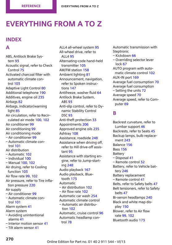
Everything from A to ZIndexAABS, Antilock Brake Sys‐
tem 93 Acoustic signal, refer to Check
Control 75 Activated charcoal filter with
automatic climate con‐trol 103
Adaptive Light Control 80 Additional telephone 190 Additives, engine oil 235 Airbags 82 Airbags, indicator/warning
light 85 Air circulation, refer to Recir‐
culated air mode 100, 102 Air conditioner 99 Air conditioning 99 Air conditioning mode– Air conditioner 99– Automatic climate con‐
trol 101Air distribution– Automatic 102– Individual 100– Manual 100, 102Air drying, refer to Cooling
function 103 Air flow rate 99, 102 Air pressure, refer to Tire infla‐
tion pressure 220 Air supply– Air conditioner 99– Automatic climate con‐
trol 101Alarm system 41 Alarm system– Avoiding unintentional
alarms 41– Interior motion sensor 41– Tilt alarm sensor 41
ALL4 all-wheel system 95 All-wheel drive, refer to
ALL4 95 Alternating-code hand-held
transmitter 105 AM/FM station 158 Ambient lighting 81 Announcement, navigation,
refer to Spoken instruc‐tions 147
Antifreeze, washer fluid 64 Antilock Brake System,
ABS 93 Anti-slip control, refer to Dy‐
namic Stability ControlDSC 93
Anti-theft protection 33 Appointments 206 Approved engine oils 235 Ashtray 108 Assistance, roadside 248 Assistance when driving off,
refer to Hill drive-off assis‐tant 95
Assistance with starting en‐gine, refer to Jump-start‐ing 248
Audio playback 167 Audio playback, Blue‐
tooth 173 Automatic– Air distribution 102– Air flow rate 102Automatic car wash 254 Automatic climate control– Automatic air distribu‐
tion 102Automatic, cruise control 96 Automatic headlamp con‐
trol 78
Automatic transmission withSteptronic– Kickdown 66– Overriding selector lever
lock 67AUTO program with auto‐
matic climate control 102 AUX-IN port 169 Average fuel consumption 70 Average fuel consumption– Setting the units 72Average speed 70 Average speed, refer to Com‐
puter 69
BBackrest curvature, refer to
Lumbar support 46 Backrests, refer to Seats 45 Backup lamps, bulb replace‐
ment 243 Balance 156 Bass 156 Battery– Disposal 41– Remote control 32Battery, refer to Vehicle bat‐
tery 246 Battery replacement– Remote control 41Belts, refer to Safety belts 47 Belt tensioners, refer to Safety
belts 47 Bi-xenon headlamps 240 Black and white map dis‐
play 150 Blower, refer to Air flow
rate 99, 102 Bluetooth audio 173
Seite 270
Reference Everything from A to Z
270 Online Edition for Part no. 01 40 2 911 544 - VI/13

Bluetooth connection, activat‐ing/deactivating 181, 191
Bluetooth hands-free sys‐tem 180
Brake assistant 93 Brake discs, breaking in 122 Brake fluid, refer to Service re‐
quirements 74 Brake force distribution, elec‐
tronic 93 Brake pads, breaking in 122 Brakes– Handbrake 60Brakes, MINI maintenance
system 237 Brakes, service require‐
ments 74 Brake system, MINI mainte‐
nance system 237 Braking, notes 123 Breakdown assistance, Road‐
side Assistance 248 Breaking in 122 Brightness on the Control Dis‐
play 74 Buckle tongue, rear– Height adjustment 48Button for starting the engine,
refer to Start/Stop button 58
CCalendar 206 California Proposition 65
Warning 7 Car battery, refer to Vehicle
battery 246 Car care products 255 Care, displays 257 Care, vehicle 255 Cargo area– Comfort Access 39– Flat loading floor 111– Multi-function hook 113– Opening from the out‐
side 37– Partition net 112
Cargo area, enlarging– Cargo cover 110Cargo area lamp, refer to Inte‐
rior lamps 81 Cargo area tailgate, refer to
Tailgate 37 Car horn, refer to Horn 14 Carpet, care 257 Car phone, refer to Tele‐
phone 180, 190 Car wash 254 CBC, Cornering Brake Con‐
trol 93 CBS Condition Based Serv‐
ice 237 CD 166 CD/DVD drives, care 257 CD player 166 Center armrest 115 Center console, refer to
Around the center con‐sole 18
Center rail 116 Center rail, refer to Storage
compartments 116 Central locking– Comfort Access 38– From the inside 36– From the outside 34Central locking system– Concept 33– From the outside 33Central screen, see Control
Display 20 Changes, technical, refer to
Safety 7 Changing wheels/tires 227 Check Control 75 Children, transporting 53 Child restraint fixing system
LATCH 54 Child restraint fixing sys‐
tems 53 Child restraint fixing systems,
mounting 53 Child seat, mounting 53
Child seats, refer to Transport‐ing children safely 53
Chrome parts, care 257 Circulation of air, refer to Re‐
circulated airmode 100, 102
Cleaning, displays 257 Cleaning, refer to Care 254 Climate 99 Climate mode– Ventilation 103Clock 68 Clock– 12h/24h format 72– Setting the time and date 72Closing– From the inside 36– From the outside 34Clutch, breaking in 122 Cockpit 14 Cold start, refer to Starting the
engine 59 Combination instrument, refer
to Displays 16 Combination switch, refer to
Turn signal/high beams/headlamp flasher 61
Combination switch, refer toWasher/wiper system 61
Comfort Access– In the car wash 40– Replacing the battery 41Comfort area, refer to Around
the center console 18 Compartment for remote con‐
trol, refer to Ignition lock 58 Compass, digital 106 Computer 69 Computer, displaying informa‐
tion 69 Condition Based Service
CBS 237 Confirmation signals for vehi‐
cle locking/unlocking 35 Connecting, mobile phone, re‐
fer to Pairing the mobilephone 180, 191
Seite 271
Everything from A to Z Reference
271Online Edition for Part no. 01 40 2 911 544 - VI/13

Consumption, refer to Aver‐age fuel consumption 70
Contacts 187, 203 Control Display 20 Control Display, care 257 Control Display, settings 73 Controls and displays 14 Control systems, driving stabil‐
ity 93 Convenient operation– Windows 34Coolant temperature 69 Cooling function, switching on
and off 103 Cooling, maximum 102 Cornering Brake Control,
CBC 93 Corrosion on brake discs 124 Cradle for telephone or mobile
phone, refer to Snap-inadapter 200
Cruise control 96 Cupholders 108 Current fuel consumption 70 Current location, storing 138 Curve lights, refer to Adaptive
Light Control 80 Cylinders, number of, refer to
Engine data 260
DDashboard lighting, refer to
Instrument lighting 80 Dashboard, refer to Cock‐
pit 14 Dashboard, refer to Dis‐
plays 16 Data, technical 260 Date– Date format 73– Setting 73Daytime running lights 79 Decorative trim, care 257 Defogging windows 100 Defroster– Rear window 100, 103
Defrosting windows 100 Defrost setting, refer to De‐
frosting windows 100 Destination entry via the ad‐
dress book 138 Destination guidance with in‐
termediate destinations 143 Destination input, naviga‐
tion 136 Digital compass 106 Digital radio 159 Dip stick, engine oil 234 Directional indicators, refer to
Turn signals 61 Displacement, refer to Engine
data 260 Display lighting, refer to In‐
strument lighting 80 Displays 16 Displays and controls 14 Displays, care 257 Displays, cleaning 257 Displays, refer to Instrument
cluster 16 Disposal– Remote control battery 41Distance warning, refer to
Park Distance ControlPDC 97
Door key, refer to Remotecontrol with integratedkey 32
Door lock 35 Door lock, confirmation sig‐
nals 35 Doors, manual operation 36 Doors, unlocking and locking– Confirmation signals 35– From the inside 36– From the outside 34DOT Quality Grades 224 Drive-off assistant, refer to Hill
drive-off assistant 95 Driving notes, breaking
in 122 Driving off on hills, refer to Hill
drive-off assistant 95
Driving on poor roads 125 Driving stability control sys‐
tems 93 Driving tips, refer to Driving
notes 122 Dry air, refer to Cooling func‐
tion 103 DSC Dynamic Stability Con‐
trol 93 DTC Dynamic Traction Con‐
trol 94 DTMF suffix dialing 185, 197 Dynamic destination guid‐
ance 152 Dynamic Stability Control
DSC 93 Dynamic Traction Control
DTC 94
EElectrical malfunction– Door lock 36– Fuel filler flap 216Electronic brake-force distri‐
bution 93 Electronic Stability Program
ESP, refer to Dynamic Stabil‐ity Control DSC 93
Emergency activation– Automatic transmission, re‐
fer to Overriding selectorlever lock 67
Emergency operation, fuelfiller flap, unlocking man‐ually 216
Emergency operation, refer toManual operation– Door lock 36Energy, saving, refer to Saving
fuel 130 Engine, breaking in 122 Engine compartment 232 Engine oil, adding 234 Engine oil, additives, refer to
Approved engine oils 235
Seite 272
Reference Everything from A to Z
272 Online Edition for Part no. 01 40 2 911 544 - VI/13

Engine oil, alternative oiltypes 235
Engine oil change intervals,refer to Service require‐ments 74
Engine oil, dip stick 234 Engine oil, filling capacity 263 Engine oil, MINI maintenance
system 237 Engine oil types, alterna‐
tive 235 Engine oil types, ap‐
proved 235 Engine, overheating, refer to
Coolant temperature 69 Engine power, refer to Engine
data 260 Engine, RPM 260 Engine start, assistance 248 Engine, starting 59 Engine, starting– Comfort Access 38Engine, starting, Start/Stop
button 58 Engine, stopping, Start/Stop
button 58 Engine, switching off 60 Equipment, interior 104 ESP Electronic Stability Pro‐
gram, refer to Dynamic Sta‐bility Control DSC 93
Exchanging wheels/tires 227 Exterior mirrors 51 Exterior mirrors, adjusting 51 Exterior mirrors, folding in and
out 51 Exterior sensors, care 257 External devices 169 External temperature dis‐
play 68 External temperature display– Changing the unit of meas‐
ure 72– On computer 72External temperature warn‐
ing 68
Externel temperature dis‐play 68
FFader 156 Failure messages, refer to
Check Control 75 False alarm, refer to Avoiding
unintentional alarms 41 Fastening safety belts, refer to
Safety belts 47 Fault messages, refer to Check
Control 75 Filling capacities 263 Filter– Refer to Activated-charcoal
filter 101– Refer to Microfilter 101– Refer to Microfilter/acti‐
vated-charcoal filter withautomatic climate con‐trol 103
First aid kit 248 First aid, refer to First aid
kit 248 Flashing when locking/unlock‐
ing 35 Flat tire– Flat Tire Monitor 86– Indicator/warning lamp 86– Run-flat tire 87– Tire Pressure Monitor
TPM 87Flat Tire Monitor FTM 85 Flat Tire Monitor FTM– Flat tire message 86– Initializing the system 86– Limits of the system 85– Snow chains 85Flat tire, wheel change 245 Floor mats, care 257 FM/AM station 158 Fog lamps 80 Foot brake 123 Footwell lamps, refer to Inte‐
rior lamps 81
Four-wheel drive, refer toALL4 95
Front airbags 82 Front fog lamp, bulb replace‐
ment 241 Front fog lamps 80 Front lamps, bulb replace‐
ment 241 Front passenger airbags, de‐
activating 83 FTM Flat Tire Monitor 85 Fuel 218 Fuel– Refer to Average fuel con‐
sumption 70Fuel, additives 218 Fuel, average consump‐
tion 70 Fuel cap, closing 216 Fuel consumption display– Average fuel consump‐
tion 70Fuel filler flap, closing 216 Fuel filler flap, opening 216 Fuel filler flap, unlocking in
case of an electrical malfunc‐tion 216
Fuel gauge 69 Fuel, saving 130 Fuel tank capacity, refer to
Filling capacities 263 Fuel tank contents, refer to
Filling capacities 263 Fuel tank, refer to Filling ca‐
pacities 263 Fuse 247
GGarage door opener, refer to
Universal garage dooropener 104
Gasoline 218 Gasoline gauge, refer to Fuel
gauge 69 Gasoline quality 218
Seite 273
Everything from A to Z Reference
273Online Edition for Part no. 01 40 2 911 544 - VI/13
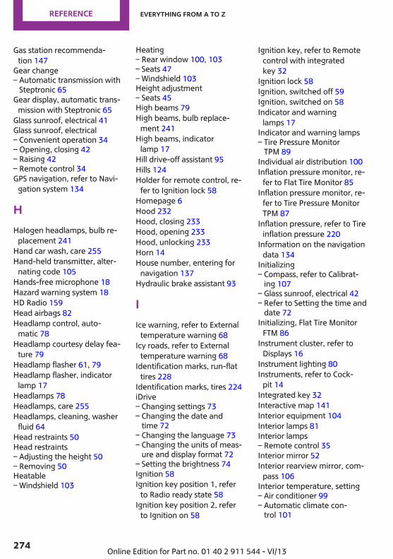
Gas station recommenda‐tion 147
Gear change– Automatic transmission with
Steptronic 65Gear display, automatic trans‐
mission with Steptronic 65 Glass sunroof, electrical 41 Glass sunroof, electrical– Convenient operation 34– Opening, closing 42– Raising 42– Remote control 34GPS navigation, refer to Navi‐
gation system 134
HHalogen headlamps, bulb re‐
placement 241 Hand car wash, care 255 Hand-held transmitter, alter‐
nating code 105 Hands-free microphone 18 Hazard warning system 18 HD Radio 159 Head airbags 82 Headlamp control, auto‐
matic 78 Headlamp courtesy delay fea‐
ture 79 Headlamp flasher 61, 79 Headlamp flasher, indicator
lamp 17 Headlamps 78 Headlamps, care 255 Headlamps, cleaning, washer
fluid 64 Head restraints 50 Head restraints– Adjusting the height 50– Removing 50Heatable– Windshield 103
Heating– Rear window 100, 103– Seats 47– Windshield 103Height adjustment– Seats 45High beams 79 High beams, bulb replace‐
ment 241 High beams, indicator
lamp 17 Hill drive-off assistant 95 Hills 124 Holder for remote control, re‐
fer to Ignition lock 58 Homepage 6 Hood 232 Hood, closing 233 Hood, opening 233 Hood, unlocking 233 Horn 14 House number, entering for
navigation 137 Hydraulic brake assistant 93
IIce warning, refer to External
temperature warning 68 Icy roads, refer to External
temperature warning 68 Identification marks, run-flat
tires 228 Identification marks, tires 224 iDrive– Changing settings 73– Changing the date and
time 72– Changing the language 73– Changing the units of meas‐
ure and display format 72– Setting the brightness 74Ignition 58 Ignition key position 1, refer
to Radio ready state 58 Ignition key position 2, refer
to Ignition on 58
Ignition key, refer to Remotecontrol with integratedkey 32
Ignition lock 58 Ignition, switched off 59 Ignition, switched on 58 Indicator and warning
lamps 17 Indicator and warning lamps– Tire Pressure Monitor
TPM 89Individual air distribution 100 Inflation pressure monitor, re‐
fer to Flat Tire Monitor 85 Inflation pressure monitor, re‐
fer to Tire Pressure MonitorTPM 87
Inflation pressure, refer to Tireinflation pressure 220
Information on the navigationdata 134
Initializing– Compass, refer to Calibrat‐
ing 107– Glass sunroof, electrical 42– Refer to Setting the time and
date 72Initializing, Flat Tire Monitor
FTM 86 Instrument cluster, refer to
Displays 16 Instrument lighting 80 Instruments, refer to Cock‐
pit 14 Integrated key 32 Interactive map 141 Interior equipment 104 Interior lamps 81 Interior lamps– Remote control 35Interior mirror 52 Interior rearview mirror, com‐
pass 106 Interior temperature, setting– Air conditioner 99– Automatic climate con‐
trol 101
Seite 274
Reference Everything from A to Z
274 Online Edition for Part no. 01 40 2 911 544 - VI/13

Internet page 6 Intersection, entering for navi‐
gation 137
JJump-starting 248
KKeyless Go, refer to Comfort
Access 38 Keyless opening and closing,
refer to Comfort Access 38 Key Memory, refer to Personal
Profile 32 Key, refer to Remote control
with integrated key 32 Kickdown– Automatic transmission with
Steptronic 66Knee airbag 82 Knocking control 218
LLamp and bulb replacement,
bulb replacement 240 Lamp, replacing, refer to
Lamp and bulb replace‐ment 240
Lamps 78 Lamps, automatic headlamp
control 78 Lamps, parking lamps/low
beams 78 Language, changing on the
Control Display 73 Lap-and-shoulder belt, refer
to Safety belts 47 LATCH child restraint fixing
system 54 Leather, care 256 Leather care 256 LEDs, light-emitting di‐
odes 240
Letters and numbers, enter‐ing 24
License plate lamp, bulb re‐placement 243
Light-alloy wheels, care 257 Light-emitting diodes,
LEDs 240 Lighter– Socket 108Lighting– Instruments 80Lighting, lamp and bulb re‐
placement 240 Lighting, vehicle, refer to
Lamps 78 Light switch 78 Limit, refer to Speed limit 91 Lock buttons on doors, refer
to Locking 37 Locking– From the inside 37– From the outside 34– Setting the confirmation sig‐
nal 35– Without remote control, re‐
fer to Comfort Access 38Locking, vehicle– From the inside 36– From the outside 34Longlife oils, alternative oil
types 235 Longlife oils, refer to Ap‐
proved engine oils 235 Low beams 78 Low beams– Automatic 78Low beams, automatic 78 Low beams, bulb replace‐
ment 241 Lower back support, refer to
Lumbar support 46 Lumbar support 46
MMain inspection, refer to Serv‐
ice requirements 74
Maintenance, refer to Servicebooklet
Maintenance, refer to Servicerequirements 74
Maintenance require‐ments 237
Maintenance systemMINI 237
Malfunction– Automatic transmission with
Steptronic 67– Door lock 36– Fuel filler flap 216Malfunction warnings, refer to
Check Control 75 Manual air distribu‐
tion 100, 102 Manual mode, automatic
transmission with Step‐tronic 66
Manual operation– Door lock 36– Selector lever lock, auto‐
matic transmission 67Manual operation, fuel filler
flap 216 Manual transmission 64 Map, destination entry 141 Map display in black and
white 150 Map view 148 Marking on approved
tires 227 Maximum cooling 102 Maximum speed, winter
tires 228 Menu operation, onboard
monitor 20 Menus, refer to Onboard
monitor operating con‐cept 21
Message list, traffic bulle‐tins 149
Messages 205 Microfilter 101
Seite 275
Everything from A to Z Reference
275Online Edition for Part no. 01 40 2 911 544 - VI/13

Microfilter– With automatic climate con‐
trol 103MINI Connected 210 MINI Homepage 6 MINI Internet page 6 MINI maintenance sys‐
tem 237 MINI Mobility System 229 Minimum tread, tires 226 Mirrors 51 Mirrors, folding in and out 51 Mirrors, interior mirror 52 Mobile communication devi‐
ces in the vehicle 123 Mobile phone, refer to Tele‐
phone 180, 190 Mobility System 229 Modifications, technical, refer
to Safety 7 Monitor, see Control Dis‐
play 20 Mounting of child restraint fix‐
ing systems 53 MP3 player 169
NNavigation 134 Navigation data 134 Navigation data, updat‐
ing 134 Navigation system– Destination entry by
voice 142Neck restraints, refer to Head
restraints 50 New wheels and tires 227 Notes 6, 207 Nozzles, refer to Ventila‐
tion 103
OOBD Onboard Diagnos‐
tics 238
OBD socket, refer to Socketfor OBD Onboard Diagno‐sis 238
Octane number, refer to Fuelquality 218
Octane rating, refer to Gaso‐line quality 218
Odometer 68 Office 202 Oil additives 235 Oil level 234 Oil types, alternative 235 Oil types, approved 235 Onboard Diagnostics
OBD 238 Onboard monitor 20 Opening and closing– Comfort Access 38– From the inside 36– From the outside 34– Using the door lock 35– Via the remote control 34Opening and unlocking– From the inside 37Operating concept of the on‐
board monitor 20 Outside air mode– Automatic climate con‐
trol 102Outside air, refer to Recircu‐
lated air mode 100, 102 Overheating of engine, refer
to Coolant temperature 69
PPairing, mobile
phone 180, 191 Park Distance Control PDC 97 Parking aid, refer to Park Dis‐
tance Control PDC 97 Parking assistant, refer to Park
Distance Control PDC 97 Parking brake, refer to Hand‐
brake 60 Parking lamp, bulb replace‐
ment 241
Parking lamps 78 Parking lamps/low beams 78 PDC Park Distance Control 97 Personal information 202 Personal Profile 32 Pinch protection– Windows 43Plastic, care 256 Pollen– Refer to Microfilter 101– Refer to Microfilter/acti‐
vated-charcoal filter 101– Refer to Microfilter/acti‐
vated-charcoal filter withautomatic climate con‐trol 103
Poor road operation 125 Position, storing 138 Postal code, entering in navi‐
gation 137 Power, refer to Engine
data 260 Power windows 43 Power windows, refer to Win‐
dows 42 Prescribed engine oils, refer to
Approved engine oils 235 Pressure monitoring of tires,
refer to Tire Pressure MonitorTPM 87
Pressure, tires 220 Pressure warning, tires 85 Profile depth, refer to Mini‐
mum tread depth 226 Profile, tires 225 Protective function, refer toPinch protection– Windows 43
RRadio 158 Radio-operated key, refer to
Remote control withintegrated key 32
Radio ready state 58
Seite 276
Reference Everything from A to Z
276 Online Edition for Part no. 01 40 2 911 544 - VI/13

Radio ready state, switchedoff 59
Radio ready state, switchedon 58
Radio setting, refer to Radioready state 58
Rain sensor 62 Random 167 Random playback 167 Range 70 RDS 159 Reading out loud 208 Rear 46 Rear fog lamp, bulb replace‐
ment 243 Rear fog lamps, indicator
lamp 17 Rear lamps, refer to Tail
lamps 243 Rear seat backrests, folda‐
ble 110, 111 Rearview mirror, refer to Mir‐
rors 51 Rear window de‐
froster 100, 103 Rear window, washing 63 Rear window wiper 63 Recirculated air
mode 100, 102 Recommended tire
brands 227 Redialing 186, 198 Releasing, refer to Unlock‐
ing 39 Remaining range for service,
refer to Service require‐ments 74
Remaining range, refer toRange 70
Reminders 208 Remote control– Battery replacement 41– Comfort Access 38– Malfunctions 35, 40Remote control, removing
from the ignition lock 58
Remote control, servicedata 237
Remote control, univer‐sal 104
Remote inquiry 185, 197 Replacement remote con‐
trol 32 Replacing wheels/tires 227 Reporting safety defects 9 Reserve warning, refer to Fuel
gauge 69 Reservoir for washer fluid, re‐
fer to Washer fluid reser‐voir 64
Restraining systems– Refer to Safety belts 47Restraint systems for chil‐
dren 53 Retreaded tires 227 Reverse gear, manual trans‐
mission 65 Road, avoiding 145 Road detour 145 Roadside Assistance 248 Roadside parking lamp, bulb
replacement 241 Roadside parking lamps 79 RON gasoline quality 218 RON, refer to Fuel quality 218 Route 146 Route criteria, route 145 Route, displaying 146 Route section, bypassing 146 RPM, refer to Engine data 260 Rubber seals, care 256 Run-flat tires 228 Run-flat tires– Flat tire 86Run-flat tires, tire inflation
pressure 220 Running lights, refer to Park‐
ing lamps/low beams 78
SSafe braking 123
Safety 7 Safety belts 47 Safety belts– Damage 50– Rear center safety belt 48Safety belts, care 257 Safety belts, indicator/warning
lamp 50 Safety belts, reminder 50 Safety systems– Safety belts 47Safety systems, airbags 82 Satellite radio 160 Saving fuel 130 Scale, changing during navi‐
gation 149 Screen, see Control Display 20 Seat adjustment 46 Seat adjustment– Manual 45Seat belts– Refer to Safety belts 47Seat heating 47 Seats– Adjusting 45– Heating 47– Sitting safely 45Selector lever, automatic
transmission with Step‐tronic 65
Selector lever lock, overrid‐ing 67
Selector lever lock, refer toChanging selector lever posi‐tions, Shiftlock 65
Selector lever positions, auto‐matic transmission withSteptronic 65
Service and warranty 8 Service data in the remote
control 237 Service interval display, refer
to Condition Based ServiceCBS 237
Service interval display, referto Service requirements 74
Service requirements 74
Seite 277
Everything from A to Z Reference
277Online Edition for Part no. 01 40 2 911 544 - VI/13

Service requirements, CBSCondition Based Service 237
Settings– Changing on the Control Dis‐
play 73– Language 73Settings and information 71 Settings, configuring, refer to
Personal Profile 32 Setting the clock, 12h/24h for‐
mat 72 Shifting– Automatic transmission with
Steptronic 66Shifting, manual transmis‐
sion 64 Shift lever– Automatic transmission with
Steptronic 65Shift paddles on the steering
wheel 66 Short commands, voice acti‐
vation 264 Side airbags 82 Side windows, refer to Win‐
dows 42 Sliding/tilting sunroof– Refer to Glass sunroof, elec‐
trical 41Slot for remote control 58 Snap-in adapter, mobile
phone 200 Socket, OBD Onboard Diagno‐
sis 238 Software applications,
iPhone 210 Software part num‐
ber 180, 190 Software update 176 Special destinations, naviga‐
tion 140 Special equipment, series
equipment 6 Speed, average 70 Speed limit 91 Speed limit– Setting 91
Speedometer 16 Speed, with winter tires 228 Spoken instructions, naviga‐
tion 147 Sport button 95 Sport program, automatic
transmission with Step‐tronic 66
Stability control systems 93 Start/Stop button 58 Start/Stop button, starting the
engine 59 Start/Stop button, switching
off the engine 60 Starting the engine 59 Start problems, refer to Jump-
starting 248 State/province, selecting for
navigation 136 Stations, stored 164 Station, storing 159 Status information, onboard
monitor 23 Steering wheel 52 Steering wheel– Shift paddles 66Steering wheel, adjusting 52 Steering wheel lock 58 Stopping, engine 60 Storage, tires 228 Storing the vehicle 257 Street, entering for naviga‐
tion 137 Summer tires, refer to Wheels
and tires 220 Summer tires, tread 225 Switches, refer to Cockpit 14 Switching off, engine 60 Switching off, vehicle 60 Symbols 6
TTachometer 69 Tailgate 37
Tailgate– Comfort Access 39– Opening/closing 37– Opening from the out‐
side 37Tail lamps 243 Tank gauge, refer to Fuel
gauge 69 Tasks 207 Technical changes, refer to
Safety 7 Technical data 260 Telephone 180, 190 Telephone, adjusting the vol‐
ume 183, 195 Temperature– Air conditioner 100– Automatic climate con‐
trol 102– Changing the unit of meas‐
ure 72Temperature, coolant, refer to
Coolant temperature 69 Temperature display– External temperature 68– External temperature warn‐
ing 68– Setting the unit 72Temperature warning 68 Text messages 205 Theft alarm system, refer to
Alarm system 41 Time– Setting the time 72– Setting the time zone 73Tire age 226 Tire identification marks 224 Tire inflation pressure 220 Tire inflation pressure– Pressure loss 86, 88Tire pressure monitor, refer to
Flat Tire Monitor 85 Tire Pressure Monitor TPM– System limits 87– System reset 88– Warning lamp 89Tire Quality Grading 224
Seite 278
Reference Everything from A to Z
278 Online Edition for Part no. 01 40 2 911 544 - VI/13

Tires– Flat tire 86– Inflation pressure 220– Inflation pressure loss 89– Pressure monitoring, refer to
Tire Pressure MonitorTPM 87
Tires, breaking in 122 Tires, changing 227 Tires, condition 225 Tires, damage 226 Tire size 224 Tires, minimum tread 226 Tires, retreaded tires 227 Tires, storage 228 Tire tread 225 Toll roads, route 145 Tone 156 Torque, refer to Engine
data 260 Towing another vehicle 250 Towing, being towed 250 Town/city, navigation 136 Tow-starting 250 TPM, refer to Tire Pressure
Monitor 87 Traction control 94 Traffic bulletins, naviga‐
tion 149 Transmission– Overriding selector lever
lock in case of automatictransmission with Step‐tronic 67
Transmission lock– Refer to Changing selector
lever positions 65Transmission, manual 64 Transporting children
safely 53 Treble, tone 156 Trip-distance counter, refer to
Trip odometer 68 Triple turn signal activa‐
tion 61 Trip odometer 68 Trips, planning 143
Trunk lid, refer to Tailgate 37 Trunk, refer to Cargo area 37 Turning lamps, refer to Adap‐
tive Light Control 80 Turn signal– Indicator lamp 16Turn signal, bulb replace‐
ment 241 Turn signals 61 Turn signals, triple turn signal
activation 61
UUniform Tire Quality Grading/
UTQG 224 Unintentional alarms, avoid‐
ing 41 Units– Average fuel consump‐
tion 72– Temperature 72Units of measure, changing on
Control Display 72 Universal remote control 104 Unlocking– From the inside 37– From the outside 34– Tailgate 39– Without remote control, re‐
fer to Comfort Access 38Update, software 176 Upholstery care 256 Upholstery material care 256
VVehicle– Identification num‐
ber 180, 190Vehicle battery 246 Vehicle, breaking in 122 Vehicle care 255 Vehicle care, refer to
Care 254 Vehicle equipment 6 Vehicle paintwork, care 256
Vehicle storage 257 Vehicle, switching off 60 Vehicle wash 254 Ventilation– Air conditioning 103Version of the navigation
data 134 Video playback, iPhone 172 Video playback, snap-in
adapter 172 Voice activation– Navigation 142Voice activation, short com‐
mands 264 Voice activation system 26 Volume, setting 156
WWarning and indicator
lamps 17 Warning messages, refer to
Check Control 75 Warning signal volumes 156 Warning triangle 248 Washer/wiper system 61 Washer/wiper system, rain
sensor 62 Washer/wiper system, washer
fluid 64 Washer fluid 64 Washer fluid reservoir 64 Washing, vehicle 254 Welcome lamps 79 Wheel change 245 Wheels and tires 220 Wheels, changing 227 Wheels, Flat Tire Monitor
FTM 85 Windows– Closing 43– Convenient operation 34– Opening 43Windows, care 255 Windows, defrosting and de‐
fogging 100 Windows, pinch protection 43
Seite 279
Everything from A to Z Reference
279Online Edition for Part no. 01 40 2 911 544 - VI/13

Windshield– Defrosting and defog‐
ging 100Windshield, defrosting, refer
to Defrosting windows 100 Windshield wash 61 Windshield washer fluid 64 Windshield wash, rear win‐
dow 63 Windshield wash, reservoir for
washer fluid 64 Windshield wash, washer
fluid 64 Windshield wiper blades,
changing 239 Windshield wiper, refer to
Washer/wiper system 61 Winter storage, care 257 Winter tires 227 Winter tires– Setting the speed limit 91Winter tires, tread 225 Wiper blades, care 255 Wiper blades, changing 239 Wiper fluid 64 Word match concept, naviga‐
tion 25
YYour individual vehicle– Settings, refer to Personal
Profile 32
Seite 280
Reference Everything from A to Z
280 Online Edition for Part no. 01 40 2 911 544 - VI/13


01 4
0 2
911
544
ue
*BL291154400W*
DRIVE ME.Online Edition for Part no. 01 40 2 911 544 - VI/13