a wind-tunnel investigation of the stalling performance...
TRANSCRIPT
.
I
MINISTRY OF TECHNOLOGY
AERONAUTICAL RESEARCH COUNCIL
CURRENT PAPERS
C.P. No. 1103*
A Wind-Tunnel Investigation of the
Stalling Performance of Two Compressor Cascades
of Different Aspect Ratios at Low Speed
M. R. A. Shaalan, ,B.Sc. Eng , Ph.D ,
Department of Mechanrcal Engineering,
The University of Liverpool
LONDON: HER MAJESTY’S STATIONERY OFFICE
1970
PRICE 10s Od b0p-j NET


C.P. No.11030 kiillOMAUTIC,i Rh'SEAkCH COUNCIL
TuRBO:~~ACRCHII~rn SUB-cOMfVIITTEB Mix-oh, 1968
A Wind-be1 Investigation of the Stalling Performance of Two Compressor Csacadea of Different Aspect Ratios at Low Speed
-& - M. R. A. Shaalsn, B.Sc.(Eng.), Ph.D., Department of Mechanical Engineering,
The University of Liverpool
SUMIViiY
Two compressor ca80ade9 of aspect ratio 2.10 ana 4ea3 ~8m tested up to the stall point in a working section with solid aide wells. A change in aspect ratio was obtained by changing the blade chord only.
. The blade section profile wss the lOCb/3OC50, staggered at 36 degrees with a space-ahord ratio of O&8, and there was no tip clearance. Reynolds number similarity was maintained but its value we8 kept above e "critical"
Substantial difference in performance is indicated between the two aspect ratios. The high aspect ratio cascade gives more deflection at the mid-span near stall, but atella first. The long chord, low aspect ratio blade stalls gently whilst a classical type of sudden stall occurs at the other aspect ratio. Higher pressure rise coefficient is observed at the high aspect ratio, increasing slightly with incidence up to the atell. point. Subatentially higher apsnwise contraction is evident with the low aspect ratio. The order of magnitude of the increase in axial velocity for both cascades is remarkably high.
Further teats show that the wall stall, which is present at each incidence, is different in the two cases. It appears that the flow near the wall in the long chord blade rotates further in the passage and the stall neer the end wall is more along the blade than along the well. In the case of the short chord, the separation areas along the blede end the wall are approximately equel.
The results for the overall performance are generally consistent with compressor work.
I List/
.
- - - -3--- - - - - - - - - - - - - - - - - - - - - - - - - - - - - - -
*Replaces A.R.C.30 063
**Nm lecturer inMechanical. Xngineering,Ai.n Shams University, Cairo, IJAR,,

List of Contents
1.
2.
3.
4.
5.
summary .00 . . .
List of Contents
Notation *.. . . .
Introduction 0. *
Apparatus . . . . . .
ee. .ee
00. . . .
. . . . . .
. . . e..
e.. . . .
Experimental Procedure and Investigation
Discussion ...............
Conclusions ...............
Ao~owledgements ............
References ...............
0e.
.e.
. . .
. . .
. . .
0.0
.0.
000
0.e
..O
0..
. . .
. . .
. . .
. . .
.00
. . *
e0.
. . .
.ee
&&
..O 1
0.e 2
..O 2
eeo 4
. . . 5
.a. 6
..o 7
.00 IO
. . . 11
. . . $1
(a) S.ylnhola
Notation
A Blade aspect ratio (blade length/blade chord)
AVR Axial velocity rstio (outlet axial velocity/inlet axial velocity)
C Fluid velocity
% Lift coefficient
c p-p1 p =-
hPC,2 Local static pressure coefficient
cx Axial component of velocity
C Y
Tangential component of velooity
R&h' Reynolds number
c2 D= c- Diffision ratio ma%
h Blade length
ha- a' Incidence angle
K Calibration factor
Id Lift force
-3-
1
P
P
8
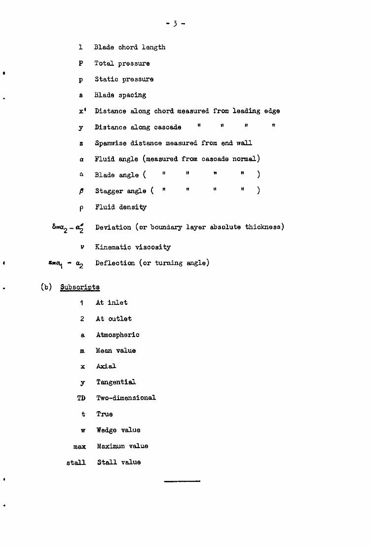
X’
Y
?i
a
a
P
P
Blade chord length
Total pressure
static pressure
Blade spaoing
Distance along chord measured from leading edge
Distance along cascade ' " M "
Spanwise distance measured from end wall
Fluid angle (measured from cascade normal)
Blade angle ( U It ' " 1
Stagger angle ( " ' ' ' )
Fluid density
6.'a2-cr; Deviation (or boundary layer absolute thickness)
Y Kinematic visoosity
"9 - 02 Deflection (or turning angle)
(b) Subsoripts
1 At inlet
2 At outlet
a Atmospheric
m Meen value
x Add
Y Tangential
TD Two-dimensional
t True
w Wedge value
max Maximum value
stall Stall value

-4-
1. Introduction
Cascade data is still a reliable basis of compressor design. Through the cascade model, en indication is gained of the behaviour of the main design variables such as air outlet angles, losses, pressure rise, stall-free operating range, etc. Data obtained from systematic cascade testing is presented in the form of correlations covering a wide range of geometry and a variety of flow conditions. These conditions have been selected to simulate, roughly, those encountered in the real machine.
The compressor designer needs cascade information not only to seleot the profile that satisfies his design requirements, but also to check on the performance of the blade sections offdesign. It is therefore essential that the blade element data covers a wide range of operation if the designer is to assess the overall characteristics of his stage.
The importance of the role of blade aspect ratio in determining the performance of an exi.al-flow compressor is well recognised. It has been shown that the overall characteristics of a compressor stage are adversely affected by increasing the aspect ratio end that severe wall stall is the primary cause of the deterioration in performance of high aspect ratio oompressorso It has been suggested that the cause of wall stall must be found and eliminated if the performance of the high aspect ratio stage is to be improved*
The influence of aspect ratio on the performance of compressor cascades was first indicated in work by Erwin and Emery& Their main conclusion was that the performance of cascades tested in a working section with porous side walls was unaffected by aspect ratio. But there was substantial evidence in Erwin end Rmery's work that the performance of cascades of different aspect ratios was different when tested with solid side walls.,
In compressor cascades - where the overall pressure gradient is adverse - the wsll boundary layer is likely to separate in the corner bounded by the end wall and the blade suction surface provided the fluid turning angle is sufficient. Also, the boundary layer, when deflected, gives rise to secondary motion behind the cascade. The threedimensional flow associated with the corner separation results in a strong streem contraction through the central part of the blade passage. None of these effects exists in a cascade tested in a working seation where the wall boundary layer is extracted completely,
It is clear that further experimental studies are needed in whioh these effects can be clarifie& Most tests on oompressor cascades in whioh the aspect ratio was the only variable have been restricted to design point operation*
Carte? (1946), tested casoades having aspect ratio 1 ,2=x34 at design point. Carter studied the effect of variation in the entry velocity profile on the losses end concluded that as the profile got worse the loss peak moved towards the mid-span location. His general conclusion was that the total loss integrated over the whole blade height increased as the aspect ratio decreased and the losses were slightly influenced by changes in the velocity profile.
Rouffignao/

Rou!?fi@d6 (1957) tested cascades having aspect rati;sl;; 1.25 and. 2.25: in all other aspects the geometry was similar. d air velocity was fixed, so that Reynolds number similarity was not
I maintained. The low aspect ratio cascade produced higher stream contraction,, A marked increased 111 deviation at the walls was evident at the higher aspect ratio; but this effect may be due to the low Reynolds number of the test in thu case.
Horlock, Shaw, Pollard and Lewkowicz lo (1964) , in their study of the effect of Reynolds number of cascade performance, tested cascades having aspect ratio 2, 3, 4 and 4.83. The high aspect ratio cascades (3.0), showed a marked increase in deviation when Reynolds number was reduced below a "critical" value (1.0 x 10⁵). The low aspect ratio cascade showed little change in performance at such low Reynolds number. ~ollara~3 (1964) also concluded tnat the centreline performance was unaffected by secondary flow developed near the walls for aspect ratios >3.0. He suggests that exial velocity ratio end the aspect ratio are important parameters in determining the stsll pout.
It was seen from this short review that the performance of compressor cascades of different aspect ratios taken up to the stall point remained to be investigated. This constituted the SUbJeCt of the work reported here0
2. Apparatus
(a) The wind tunnel. j The solid side wall blower tunnel No, 2 of the Mechanical Engineering
Departmant, Liverpool University, was used for the present investigationa Modifications of the working section and the traversing equipment were introduced. The mechenum for incidence varying is shown schematically in FigDlo
(b) -cascades
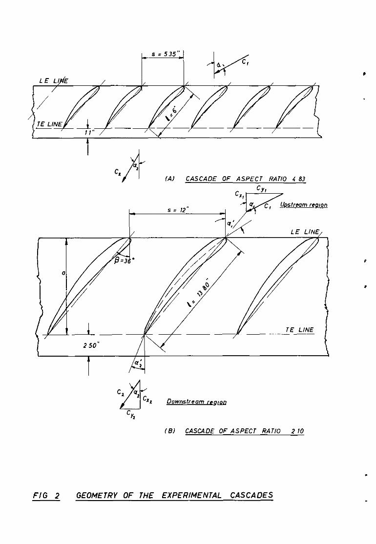
Two geometrically Identical cascades of profit lOC~3OC50 were built: one of aspect ratio 2.10 and the other of aspect ratio &83. In order to maintain the ratio of the boundary ls,yer thickness to the blade length, and. thus reduce the number of variables, it was necessary to change the blade chord only, for a change in aspect ratio,
The determination of the chord length was governed by (i) the dimensions of the existing working section, (ii) the space-chord. ratio selected (0,875), and (iii) the practical minimum number of blades in cascade, (see Ref. 18 0 5 The geometry of the experimental cascades is summarised. by the following table:
A = 2.10 A = 4083
Profile 10cd3cC50 10c4/30c50
Space/chord 0.87 0.89
Stagger (deg) 36 36
a; and a;('1 ) 51 and 21 51 and 21
Chord length (in.) l3,80 6
Span (inches) 29 29
The/
-6-
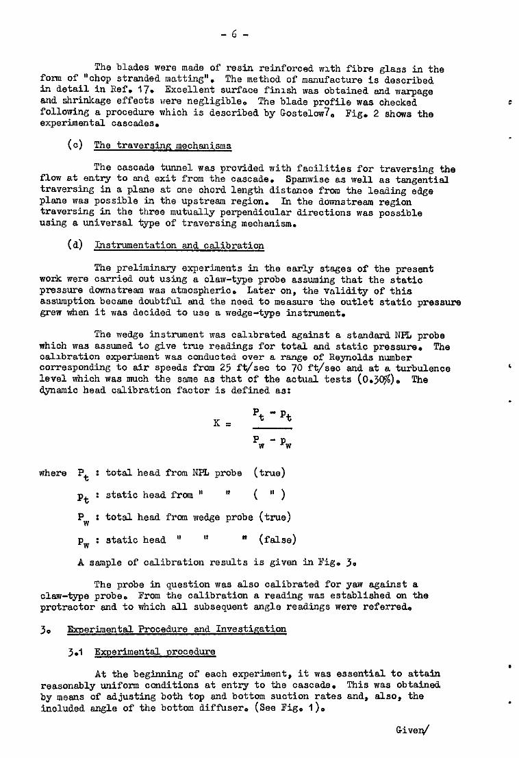
The blades were made of resin reinforced with fibre glass in the form of "chop stranded matting". The method of manufacture is described in detail in Ref. 17. Excellent surface finish was obtained end warpage and shrinkage effects were negligible. The blade profile was checked following a procedure which is described by Gostelow7s Fig. 2 shows the experimental cascades.
(c) The traversinp mechanisms
The cascade tunnel was provided with facilities for traversing the flow at entry to and exit from the cascade. Spsnwise as well as tangential traversing in a plane at one chord length distance from the leading edge plane was possible in the upstreem region. In the downstream region traversing in the three mutually perpendicular directions was possible using a universal type of traversing mechanism.
(a) Instrumentation and calibration
The preliminary experiments in the early stages of the present work were carried out using a claw-type probe assuming that the static pressure downstreem was atmospheric. Later on, the validity of this assumption became doubtful end the need to measure the outlet static pressure grew when it was decided to use a wedge-type instrument.
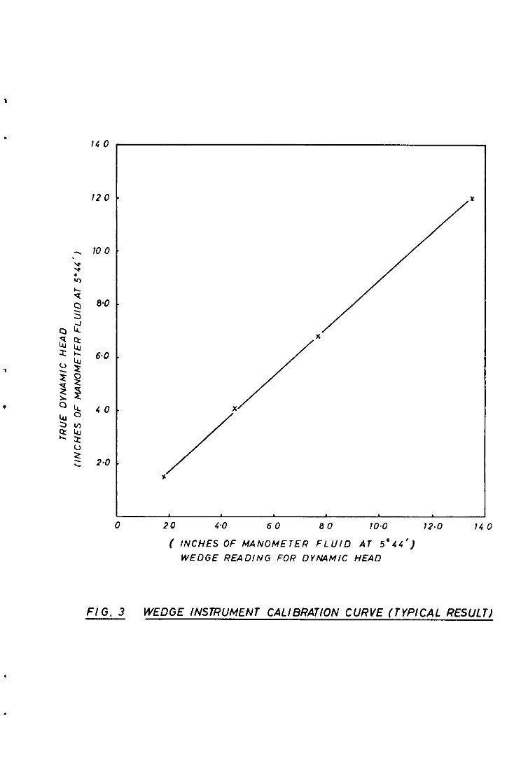
The wedge instrument was calibrated against a stendard NPL probe which was assumed to give true readings for total and static pressure. The calibration experiment, was conducted over a range of Reynolds number corresponding to air speeds from 25 ft/sec to 70 ft/seo and at a turbulence level which was much the same as that of the actual tests (O.jC$). The dynamic head calibration factor is defined as:
K= pt -*t pw - pw
where P t : total head from NF% probe (true)
*t : static head from U H ( V )
P, I total head from wedge probe (true)
PW : static head ' It m (fslse)
A sample of calibration results is given in Fig. 3.
The probe in question was also calibrated for yaw against a claw-type probe. From the calibration a reading was established on the protractor snd to which sll. subsequent angle readings were referred-
3. Experimental Procedure and Investigation
3.1 Experimental Drocedure
At the beginning of each experiment, it was essential to attain reasonably uniform conditions at entry to the cascade. This was obtained by means of adjusting both top and bottom suction rates and, also, the included angle of the bottom diffuser* (See Fig* I)*
Given/

-7-
Given low free-stream turbulence intensity, sufficiently low values of Reynolds number give rise to lsminar separation over most of the blade suction surface. This separation msy ooour at low incidence resulting
. in high loss0 Horloclc, Shaw, Pallard and LewkowicslC have shown that there is a minimum value of Reynolds number to have no effect on the performance - a conclusion which was reached also by Rhodenl5. This "oritical value" is about 1.0 x 10⁵ for the cascade under investigation, Reynolds number value in the present work was varied from 1.2 x 10⁵ to 3.5 x 10⁵.
3.2 Investigation
The mid-span performance of cascades of different aspect ratios was first exsmined. When significant differences in performance beceme evident, further tests were conducted in an attempt to explain the differences. In this respect, surveys of total, static pressure and flow angle were made extending from the mid-span location to the end wall and covering one blade pitch. Sets of pressure distribution were recorded, not only at centreline, but also at off-centreline locations gradually approaching the side well.
Details of the investigation may best be presented by the following table:
Test
7 Mid-section performance
Profile Pressure Distribution
Area - traverses
Location (in;~;jfrom
14&
lL$.
1 l&+-l
I&-$
@ = 90-y Results on Degrees Re Fig. Nos.
37 - 26 1.2 x I@-- (4)~(7) 3.5 x 16
37 -- 26 1.2 x 10⁵, 16
(15)~-(20) 3.5 x
37 and 30 2-O x 105 (21)~-(24
37 and 30 2.0 x 10⁵ (8)~-(II 1
m : Cascade angle to the horizontal direction (see Fig. l)o
4. Discussion*
4.1 The overall centreline performance
The most interesting result is the variation of fluid. deflection with incidence which is shown by Fig. 4.a. Whilst there is virtually no difference in deflection between the two cascades near design, the deflection from the higher aspect ratio is markedly higher at near-stall operation. A classical type of abrupt stall is exhibited. by cascade 5,
the/ -------- __-------------- ------------- * For convenience throughout the discussion, oasoade of aspect ratio 4-83 and cascade of aspect ratio 2.10 will be labelled Cascade 5 and Cascade 2 respectively.

-8-
the type that had been observed by Howell 11 and others. Cascade 2 (which
has not been tested by howell) stalls gently. On the other hand, stalling of the higher aspect ratio is seen to have taken place at an incidence some 3 degrees less. The negligible effect of Reynolds number on the result may be seen from the plot.
cascade is The variation of the non-dimenslonsl pressure rise produced by the
given by Fig* l+b. Both curves indicate but slight variation in the pressure coefficient over the incidence range. However, the two results are significantly different. The reason for this will be made clear later.
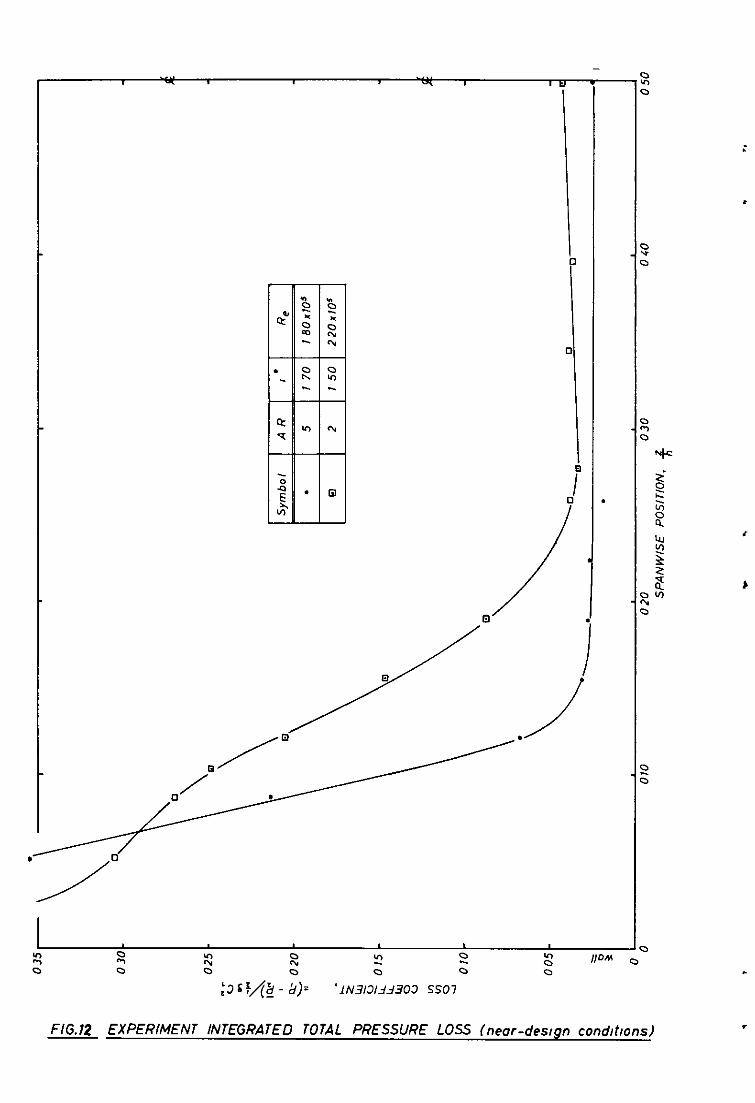
The corresponding variation of the fluid outlet angle with incidence together with the total pressure loss are given by Figs. 5a and 5b. Losses at cascade 5 suddenly rise at stall to about 16% of the inlet dynamic head. A gradual increase in the loss coefficient is shown by the low aspect ratio cascade.
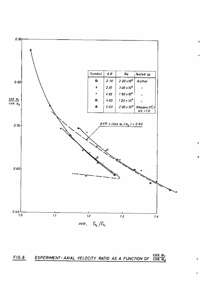
Prom measurements before and aft of the cascade, the centreline pitch-averaged axial velocities were derived. The axial velocity ratio (AVR = z h
x2 xi ) was plotted versus the ratio (cos a,/cos a,). If the AVR
is taken as a measure of the amount of fluid contraction, then it may be seen from Fig. 6 that the flow contracts more at the low aspect ratio. The order of magnitude of the contraction for both aspect ratios is strikingly high (1.30 - 1.40). The result for cascade 5 is in almost exact agreement with that obtained by Rhoden' for aspect ratio 3 but with unity space-chord ratio. Another important result, seen from the contraction curve, is the sudden reversal of the curve at stall, for cascade 50 This is associated with the sharp increase in the total pressure loss of Fig. 5b and the outlet angle of Fig. ja. Cascade 2 shows a continuing increase in contraction - which is consistent with the loss and outlet angle variation observed. Rhoden's results do not show a reversal on the contraction, probably because he had not stslled his cascade completely.
4..2 'Vsll stall"
Plsll stall in compressor oasoades has been observed by many researoh workers. It is a result of the interaction of the well and the profile boundary lsyers in the region bounded by the "end-wall" and the blade suction surf ace. The presence of rotation, caused by the secondary vorticity resulting from the deflection of the well boundary layer, causes the separation region to propagate along the blade towards the centreline and the separation is partly along the wall and partly along the blade. The relative extent of the separation zone on the wall and the blade depends on the adverse pressure gradient and the severity of the secondary vorticity leading to the rotation of the fluid in the blade passage near the end wall0
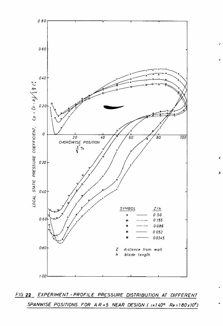
Wall stall was also observed by the present author. Figs. 8 - 11 show the total pressure contours behind the cascade, indicating a region o? zero flow in the corner. The measurements were accompanied by severs unsteadiness in that region. The flow was complete1 g tangential (a,= 90°) - the type of flow that had been observed by Horlock and which was comprehensively investigated by ArmstrongI. The rotation of the total pressure contours is slso evident. Considerable growth of the separation zone with incidence is seen from the plots. It may be seen also that while wall separation is present, there is no sign of two-dimensional stsll at the mid-span even at a high incidence. Figs. 21 - 24 showing the profile pressure distribution at spsnwise locations close to the end wall prove the existence of partial separation on the blade suction surface in the corner region.
,

-v-
Wall stall also modifies the outlet angle from a compressor cascade and gives rise to the disparity that o curs between predlctlons from secondary flow theories and experiment. Horlock 8 , Horlock, Percival, Louis and
. Lakshimlnaraysnav, and Armstrong1 have shown that the maximum variation in outlet angle from a compressor cascade occurs at more than twice the entry boundary layer thiclmess from the end-wall. This result is confirmed in Figs. 14 and15.
4.3 Increase in axial veloci*
The principal effect of wall stall is the destmction of the t<ro-dimensionality of the mainstream and the consequent increase in E&J velocity6 The effect of the enormous inorease in axid velocity observed on the pressure rise may be seen from l+rg. 25. In this figure the inlet dynamic head available for pressure rise has been broken down to various componentso It is clear that the increase in axial velocity is the predoninant cause of the deterioration of the static pressure rise ooefficien& The effect of tot&J. pressure losses is small until close to stall, when it becomes dominsnto
4.4 Total pressure contours
In order to further explain the different performance, detailed investigation behind the cascade was carried out. Figs, 8 - II show contours of non-dimensionalised total pressure relative to the atmospheric condition, and indioate a difference in the flow pattern behind the cascade. It may be seen by comparing the plots that the nature of the end-wall stall is differen& The longer chord blade (lower aspect ratio) shows a separation region which I extends more along the blade than along the wall. This is a secondary flow effect, since, with the longer channel, the flow has time to rotate further. For the low ohord (high aspect ratio) the separation areas on the end-wall
. and suction surfaoe are approximately equal. Further, the separation area is bigger for the lower chord and there is bigger contraction through the mid-span (see Zig. 6). This difference in the 130~ pattenl explains the different performance whxh ha:: been discussed. Ihe difference in the fluid contraction is responsible for the difference in the pressure rise prior to stall. The stall mechanism determines the hehatiour of the performance thereafter. The considerable movement of the end+vall stall towards the centreline explains the gradual stall of the low aspect ratio. The continuing increase in axial velocity shovm by the low aspect ratio cascade(Fig. 6) means that the wake blockage stays unimportant compared to the mall stall in this case. In the other case (A = 4.83), the wall stall becomes unlmportent at "mainstream" stall when the wake blockage has beoome so large that both the deviation and the total pressure losses increase sharply and the axial velocity ratio falls consequently. Again, this effect may be attributed to secondary flow. Not only is the secondary flow more severe for the low aspect ratio but EdsO because there is more freedom for rotation its effect is trensmitted further along the blade. This result is seen from Figs. 14 - 15, where the underturning has its peak at about twice the entry boundary layer thickness from the wall for cascade 5 whilst the peak occurs at more than three times the same thickness from the wall in the case of cascade 2. The earlier stall of cascade 5 may be explarned as due to the higher adverse pressure gradient associated with the smaller contraction.
. 4.5 Profile pressure distribution
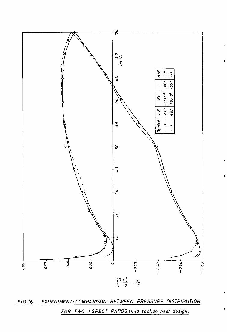
Severel sets of pressure distributions were recorded for both cascades. The better unstalled performance of cascade 5 is evident fran Figs. 16 and 17. The effect of the difference in axial velocity ratio is also seen xn these plots, being pronounced near stall. Comparison of the
pressure/

- 10 -
pressure distribution at su fficiently high incidence (Fig. 18) (when cascade 5 has already stalled) shows the marked deterioration in the pressure distribution on the rear hslf' of the suction side of the high aspect ratio blade. Although the axial velocity ratio is much lower in this case, the separation of the boundary leyer on the suction side is so severe that the pressure curve has flattened completely near the trailing edge.
Figs 21 - 24 show plots of pressure distribution recorded at each aspect ratio for off-centreline locations and they correspond to the total pressure contours of Zigs. 8 - 11~ The deterioration of the lift coefficient near the wall is evident. These results also oonfirm the conclusions from the total pressure contours in that they indicate the blade stall near the blade end which is induced by the slow moving fluid in the corner region.
4.6 Comparison with comnressor results
The performance of axial flow compressors has been shown to be adversely affected by increase in the blade aspect ratio. High aspect ratio compressors generelly have steep characteristics, whereas low aspect ratio compressors have a wider range of unstalled operation. There is general agreement between this result and the cascade result given here, in which a large incidence range is observed. However, the characteristics of low aspect ratio compressors show higher pressure rise. This is probably due to a marked drop in the total pressure loss with decrease in the aspect ratio in the case of the compressor. It is the total pressure loss rather than the increase in axial velocity that is thought to be playing en important role in affectin the compressor characteristics.
-5 This argument is based on results
by F&ml , who tested two low speed compressors of aspect ratio I end Z. However, it should be noted that Fahmi's higher aspect ratio is the present author's lower-
56 Conclusions
(1) The oerfonnsnce of cascades varies substantially with aspect ratio
Cascade 5 gives higher deflection near stall and stalls earlier then cascade 2. The stall of cascade 5 is abrupt and is associated with a steep increase in total pressure loss end deviation end a sudden reduction in axial ratio. The stall of cascade 2 is gradual. The low aspect ratio produces greater contraction on the centreline, especially near stall,
(2) The enormous fluid contraction accounts for the deterioration in static pressure rise in both oases prior to stall.
(3) The nature of the end-mall stall changes with aspect ratio
The longer passage of the lower aspect ratio cascade gives the flow more time to rotate and the separation area is carried more along the blade then along the walL In the other case, the separation areas on the end-wall end the blade are approximately equal,
(4) The cascade results are generally consistent with compressor resultso

- II -
Acknowledgements
The author is indebted to Professor J. H. Horlock, Engineering . Department, Cembrdge University, and Professor J. F. Norbury, Department
of Mechanical Engineering, Liverpool University, under whose supervision the work was carried out.
He would like to record his appreolation of the asslstanoe given by the staff of the pattern workshop of the Department of ldeohnical Engineering, Liverpool University, in the preparation of the equipment.
The British Ministry of Aviation sponsored the proJeot and the Government of the United Arab Republic (Egypt) supported the author financially,
%?a Author(s1
1 W. D. hmstrong
2 A. D. S. Carter
3 A. D. S. Carter I
, 4 J. R. Erwin and J. C. Emery
5 G. J. S. Fshmi
6 A. R. Felix and J. C. %ery
7 J. P, Gostelow
8 J. H. Horlock
9 J. H. Horlock, P. M. E. Percival, J. F. Louis .sn!d. B. Lakshiminarayena
References
Title. etc,
The Non-Uniform flow of Air through Cascades. Ph.D. Thesis, Cambridge University, (1954).
NGTE Memorandum M3, (196).
The Low Speed Performance of Related Aerofoils in Cascade. ARC C.P.No.29, (1949).
The Effect of Tunnel Configuration and Testing Technique on Cascade Performance. NACA T.N. No.2028, (1950).
The Effect of Blade Aspect Ratio on the Performance of Axial-Flow Compressors. Ph.D. Thesis, Liverpool University, (1967).
A Comparison of Typical National Gas Turbine Establishment and NACA Axial-Flow Compressor Blade Sections in Cascade at Low Speed. NACA T.N, lio.3937, (1957).
The Accurate Prediction of Cascade Pa fOI%mnCe. Ph.D. Thesis, Livenpool University, 1 1965).
Aerodynamics of Axial.-Flow Turbomachines. Ph,D. Thesis, Cambridge University, (1955).
Well Stall in Compressor Cascades. Journal of Basic Engineering0 Trans. ASME, Vo1.81, Series D, (1959).

- 12 -
Title, etc.
Reynaldr, Number Effects in Cascades and Axial-Flow Compressors. Journal of Bngineering for Power. Tram. ASME, Vo1.86, Series A, pp.236~242. (1964).
The Present Basis of Aaial Flow Compressor
i%4& M. 2095 (1942).
Preliminary &port on the Influenae of Aspaat Ratio on the Performanae of Axial-Flow Compreesore. Rep. No. 1062-1, (1963). Northern Researoh and Engineering Corporation.
Low Speed Performanoe of Two-Dimensional Cascades of Aerofoile. Ph, D. Thesis, Liverpool University (1964).
Some Experiments at Low Speed on Compreesor Caaoadea. Journal of Engineering for Power. Trans. ASME, Vol. 89, Series A, No. 3, pp. 427-436. (1967).
Effects of Reynolds Number on the Flow of Air through a Caaoade of Compressor Blade@. ARC R. 8 M. 2919. (1952).
Behaviour of Compressor Caacadas of different Curvature and Aspeot Ratioa. ONRRA TN 39, 1957.
The Stalling Performance of Compressor Ceeoadea of Different Aspect Ratios. Ph.D.Thesls, Liverpool University, (1967).
Development InTeohniques of Mesauring Representative Mid-span Loeaee of Turbine Blades in Ceacade. A.&C. 29 244 - P.A.1233 (1967).
No. Author(s1
10 J. Ii. Horlook, R. Shaw, D. Pollard and A. K. Lewkodce
11 A. It. Howell
12
13 D. Pollard
D. Pollaxd ad J. P. Gostelor
15 H. G. Rhoden
16 C. Rouffignao
47 Y. R. A. Shaalen
18 A. Smith
,
.

/
FIG 1 MECHANlSM FOR INCIDENCE VARYING
c* (Al CASCADE OF ASPECT RATIO 4 83
5 = 12’,
(81 CASCADE OF ASPECT RATIO 2 10
FIG 2 GEOMETRY OF THE EXPERIMENTAL CASCADES
L
14 0
12 0
y 100
:: t-3
/
*
x
x /
1 /
0 20 4.0 60 80 10.0 1.7.0 14 0
( INCHES OF MANOMETER FLUID AT 5’44’)
WEDGE READING FOR DYU4MIC HEAD
FIG. 3 WEDGE INSTRUMENT CALIBRATION CURVE (TYPICAL RESULT)

FLUID DEFLECTION
RL?
22x 10” 1 33 x 10s
19x10s
125x105 1
-1 *I l 3 +5 .7 +9 +ll l 13 INCIDENCE. I E a, - cy; degrees
& EXPERIMENT-PERFORMANCE OF TWO CASCADES OF DIFFERENT
ASPECT RATIOS PRESSURE RISE AND DEFLECTION
.

30
36
32
31
28
& 0.05
OUTLET ANGLE
.
Key as rn F/g(
TOTAL PRESSURE LOSS /
a
/ /
-I I 3 5 7 9 I1 13
INCIDENCE, ,=a, -Q,’
NG.5 EXPERIMENT-PERFORMANCE OF TWO CASCADES OF DIFFERENT ASPECT RATIOS : MID-SECTION OUT1 ET
ANGLE AND TOTAL PRESSURE LOSS
0
0
cos - cos
0
0
0
Symbol AR Symbol AR Re Re rested by rested by
I3 2 10 I3 2 10 220~10~ 220~10~ Author Author
t 2.10 t 2.10 3.30 105 3.30 105 x x ,I ,I
. . 4 83 4 83 190x10’ 190x10’ ,# ,#
0 4 83 0 4 83 125 x 10’ 125 x 10’ ,, ,,
A 3 00 A 3 00 2 00x 10’ 2 00x 10’ Rhoden Rhoden 0: 0: s/c=10 s/c=10
11 II 13
AVR. G* pi,
- 1 4
FIG. 6 EXPERIMENT- AXIAL VELOClTY RATIO AS A FUNCTION OF ‘=a

VELOCITY RATIO
WC
10
, -
O-
O-
O-
V-
iO-
KEY AS IN FIG /
LIFT COEFFICIENT
(hosed on vector meo” velocrty)
+ 13
FIG. 7 EXPERIMENT- PERFORMANCE OF TWO CASCADES OF
DIFFERENT ASPECT RATIOS: VELOCITY RATIO AND
LIFT COEFFICIENT

3 zi
-020 :
MID- WAKE LINE
-080
020 030 040 050 9 1450” SPANWISE POSITION, z/h
.

S/d ‘NOIlISOd 3SlMH311d
FIG. 9 TOTAL PRESSURE CONTOURS FOR AR=5 NEAR DESIGN (I = l.70w Re = 180~10~)

/ /I / / .I
VA ‘NOlllSOd i’SIMH31ld 1 l/DM
FIG.10 EXPERIMENT- TOTAL PRESSURE CONTOURS FOR AR= 2 NEAR STALL II P840° Re = 2.20 x 10⁵ )

I I 8 I
S/L ‘NOIlISOd 3SIMWlld
F1G.f I TOTAL PRESSURE CONTOURS FOR AR=5 NEAR STALL
II = 8200 Re = 1 80 x 10”)
2 0
u 0 :3 Sf& - a)= ‘lN3/3/jj303 SS07
EXPERIMENT INTEGRATED TOTAL PRESSURE LOSS (near-design condhons)

EXPERIMENT- INTEGRATED TOTAL PRESSURE LOSS Inear-stall condhons) FIG.13

FIG.14 EXPERIMENT- OUTFLOW ANGLE AT MID-PITCH POSITION ( near design)
t

/ D I
EXPERIMENT - OUTFLOW ANGLE AT MID-PITCH POSITION (near-stall condhonsl FIG 15
\ \ \
\ ‘\ ! \ \ \ \a \ \ \ \
O\
\
\ \ ‘\
FIG 16 EXPERIMENT- COMPARISON BETWEEN PRESSURE OlSTRlBUTlON
FOR TWO ASPECT RATIOS (m/d sect/on near design)

02
cp +* 2 ,
-0;
-04
-06
-i38
-10
-12
1
P’ I/
/ //,
--.x-o- A=4 83 ,=820’ (AVR=lZB)
0 A=220 ,=8 40 (AVRz133)
Re = 2 0x10’
,
FIG 17 EXPERIMENT-COMPARISON OF PRESSURE DISTRIBUTIONS AT
NEAR-STALL CONDITIONS

loo- a
Oao.\ 0 0 60 .
! O,LO . t\.
\ b ,.-----yo,------- ---~=O-e--o-O\n :~,-o----o
020.
5
n nn
PRESSURE LXSTRIBUTION
-0-A-483, q,=61 60’fRe=180x1051
-0-A ~2.10, q 561 Ed fRe =20x 10”) I
F/G. 18 EXPERIMENT-COMPARISON OF PRESSURE DISTRIBUTIONS
AT STALLED CONDITIONS
c
,
.-
.
040
020
CP
0
- 0.20
-040
-0.60
-0.80
- I*00
-1.20
/. /.
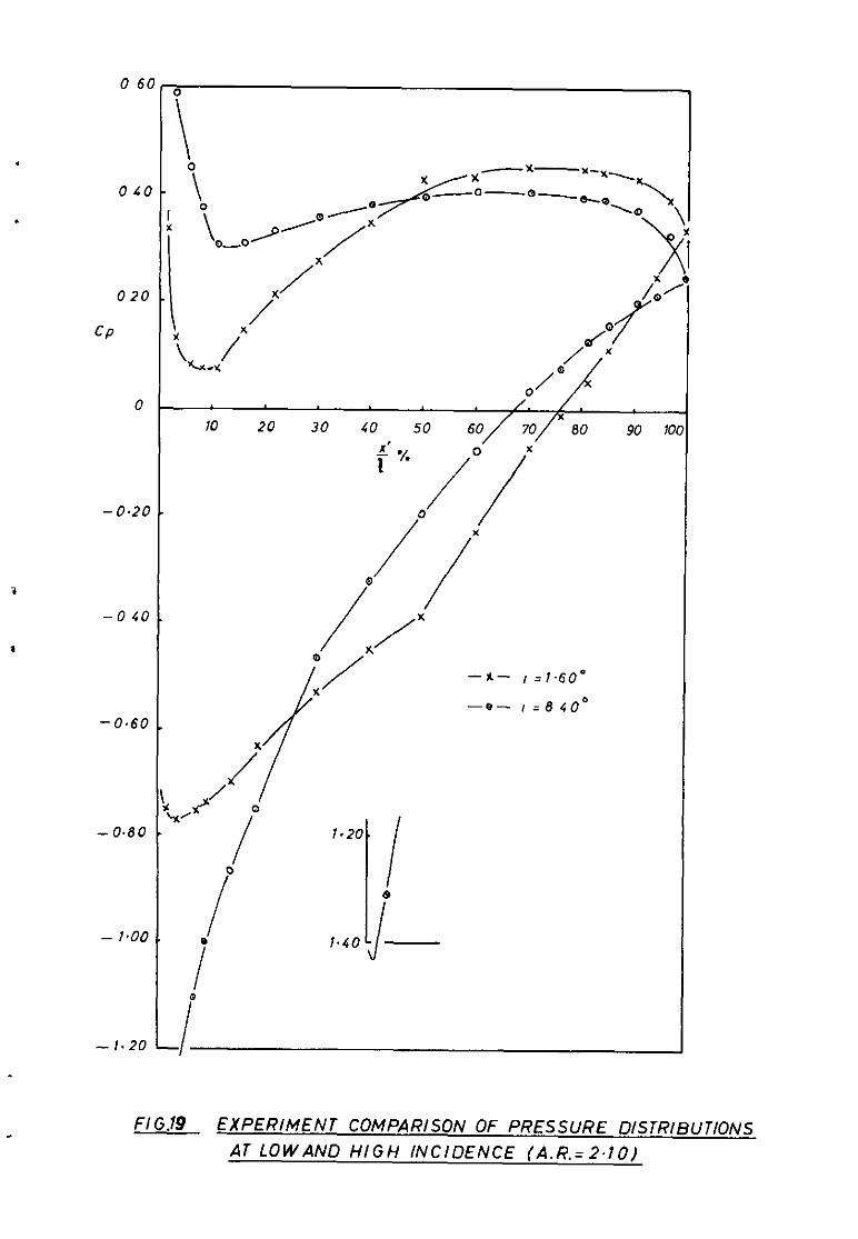
10 20 30 40 50 60 70 80 90 10 .d ‘/ 7 * /*
“20. I 8 1.40 -J
FI G.19 EXPERIMENT COMPARISON OF PRESSURE DISTRIBUTIONS AT LOWAND HIGH INCIDENCE (A.R.=2.10)

0 41
02
CP
0
-02
-0 61
-0 81
-10.5
-1 2c
0 60-
O-
O-
O-
I*
I
!I-
9-
,_
)-
c FIG. 30 EXPERIMENT- COMPARISON OF PRESSURE DISTRIBUTIONS AT
LOW AND HIGH INCIDENCE (A R=C 831

.
FIG 21 EXPERIMENT-PROFILE PRESSURE DISTRIBUTION AT DIFFERENT SPANWISE PCSlTlONS
(A R.=2, NEAR DESIGN(i=l 70°),Re=2~20r105)
80-
‘60.
r40 -
120-
0 .-
IZO-
)40-
h I
t 60:“1
: “t
MO -
oo-
. --- 0 50 P - 0 155
c - 0086
q - 0052 0 - 00345
2 d/stance from wall h blade length
F/G 22 EXPERIMENT -PROFILE PRESSURE DISTRIl3UTlON AT DIFFERENT
SPANWISE POSITIONS FOR AR=5 NEAR DESIGN (1=140” Re=180xIOs)
.

h *i \
f/G 23 EXPERIMENT-PROFILE PRESSURE DISTRIBU T/ON AT DIFFERENT SPANWISE POSITIONS
(AR=2, NEAR STALL{,=0 SO), Re =2 20 ~10’)

0t
ot
04
-12
-14
-16
0 0 293
0 0 224
a 0 190
I @ 0 155
x 0 121
A 0 052
. 0 017
FIG 24 EXPERIMENT- PROFILE PRESSURE DISTRIBUTlON AT DIFFERENT
SPANWISE POSITIONS (AR=5 NEAR STALL(I=83°)Re=180x10’)
.

090 -
oao-
070-
; 060-
2 2 x
3 $ 050-
L lu
2 25 040-
lo 4
2 030-
0 20
0 - 10
Performance mcludng effect
of dwotron from nom’/ values
h’,sod DerfQ~“?O‘Ke mcludmg
effects mcluded)
0/ -1 +I +3 t5 l 7 +9 if1 + 13
INCIDENCE, I= ( a, - a,‘)’
FIG. 25 FRACTIONAL CHANGES IN DYNAMIC HEAD 1N COMPRESSOR
CASCADES (AR =4 83) .

. *. . .

A.R.C. C.P. No.1103 28th March, 1968 M.R.A. Shaalan
A WIND-TUNNEL INVESTIGATION OF THE STALLING PERFORMANCE OF m0 COMPRESSOR CASCADES OF DIFFERENT ASPECT RATIOS
AT LOW SPEED Two compressor cascades of aspect ratlo 2.10 and 4.83 were tested up to the stall point in a working sectIon with solid side walls. A change in aspect ratlo was obtained by changing the blade chord only. The blade section profile was the lOC~jOC50, staggered at 36 degrees with a space-chord ratio of 0.88, and there was no tip clearance. Reynolds number sullarlty was maintained but its value was kept above a "critxal" value.
The/
A.R.C. C.P. No.1103 28th March, 1968 M.R.A. Shaalan
A WIND-TUNNEL INVESTIGATION OF THE STALLING PERFOPUNCE OF TWO COMPRESSOR CASCADES OF DIFFEFBNT ASPECT RATIOS
AT LOW SPEED Two compressor cascades of aspect ratio 2.10 and 4.83 were tested up to the stall point in a working sectlon with solid side walls. A change in aspect ratio was obtained by changug the blade chord only. The blade sectlon proflle was the lOCl+/jOC50, staggered at 36 degrees with a space-chord ratio of 0.88, and there was no tip clearance. Reynolds number simllarlty was malntalned but its value was kept above a "critical" value.
The/
A.R.C. C.P. No.1103 28th March, 1968 M.R.A. Shaalan A WIND-TUNNEL INVESTIGATION OF THE STALLING PERFORMANCE
OF TWO COMPRSSSOR CASCADES OF DIFFERENT ASPECT RATIOS AT LOW SPEH,
Two compressor cascades of aspect ratlo 2.10 and 4.83 were tested up to the stall point In a woriung se&Ion with solld side walls. A change In aspect ratlo was obtalned by changing the blade chord only. The blade sectIon proflle was the lOC4/3OC50, staggered at 36 degrees with a space-chord ratlo of 0.88, and there was no tip clearance. Reynolds number slmilarlty was malntained but Its value was kept above a "critical" value.

The high aspect ratio blade gave more deflection at mid-span near stall, but it stalled earlier and suddenly. The low aspect ratio blade stalled more progressively. High pressure rise coeffxlent is observed at the high aspect ratlo, increasing slightly with incidence up to the stall point. The increase in axial velocity for both cascades was remarkably high, a greater spanwise contraction being evident for the low aspect ratio.
Area traverses downstream showed that the wall stall for the high aspect ratio blade was nearly equally distributed between the blade surface and the end wall, whilst for the low aspect ratio blade it was shifted towards the blade surface.
The high aspect ratio blade gave more deflection at mid-span near stall, but it stalled earlier and suddenly. The low aspect ratio blade stalled more progressively. High pressure rise coefficient IS observed at the high aspect ratio, increasing slightly with lncldence up to the stall pomt. The increase in axial velocity for both cascades was remarkably high, a greater spanwise contractlon being evident for the low aspect ratlo.
Area traverses downstream showed that the wall stall for the high aspect ratlo blade was nearly equally dmtributed between the blade surface and the end wall, whilst for the low aspect ratio blade It was shifted towards the blade surface.
The high aspect ratio blade gave more deflection at md-span near stall, but It stalled earlier and suddenly. The low aspect ratio blade stalled more progressively. High pressure rise coefficient 1s observed at the high aspect ratio, increasing slightly with incidence up to the stall pomt. The increase m axial velocity for both cascades was remarkably high, a greater spanwise contraction being evident for the low aspect ratio.
Area traverses downstream showed that the wall stall for the high aspect ratlo blade was nearly equally distributed between the blade surface and the end wall, whilst for the low aspect ratio blade It was shifted towards the blade surface.


0 Crown copyright 1970
Prmted and pubhshed by HER MAJESTY’S STATIONERY OFFICE
To be purchased from 49 High Holborn, London WC1
13a Castle Street, Edmburgh EH2 3AR 109 St Mary Street, CarddT CFI IJW
Brazennose Street, Manchester M60 8AS 50 Farfax Street, Bristol BSl 3DE
258 Broad Street, Blrmmgham I 7 Lmenhall Street, Belfast BT2 8AY
or through any bookseller
C.P. No. 1103*
1
Prmted m England
.
C.P. No. 1103* ’