a wearable iot device for users with mild cognitive impairment needs · pdf file ·...
TRANSCRIPT
A WEARABLE IoT DEVICE FOR USERS WITH
MILD COGNITIVE IMPAIRMENT NEEDS
AUTHOR: IAN MARTINEZ GARCIA
PROFESSOR: Mr. FULVIO CORNO
TORINO, JULY 2016

1
ABSTRACT
This project constitutes a technical proposal related to a system of tele-assistance
for elderly and disabled people. The target users of the system usually reject new
technologies as they considered them an imposed elements which interfere their daily life.
The tele-assistance device presents several advantages since it can be easily used and due
to its reduced size it can be placed either on any garment or complement such a belt or a
wallet, thus becoming a wearable element that does not interfere on the user daily life.
By means of the service offered by the system, it is sought to guarantee a quick
and effective service of attendance by means of the identification of possible emergency
situations throughout users’ daily life. For its functioning, it has been utilized one of the
technologies already used for the localization of devices that is based on mobile networks.
By using the device and knowing the patient's location, it will be possible to offer a quick
and efficient attendance in the event of being required either the patient is inside or outside
home.
The project also includes a theoretical study about Energy Harvesting, a
concept which is considered a keystone to improve power life in this kind of wearable
devices
2
ACKNOWLEDGMENTS
This project is the result of the collaboration of two entities of Turin city.
On the one side the POLITECNICO DI TORINO, represented by Professor Mr. Fulvio
Corno. On the other side, CARETEK Company, represented by Mr.Luca Feletti.
First, I would like to thank my supervisor, Prof. Corno, for providing me with an
incredible opportunity to work with a company in order to finish my studies. I also thank
Mr.Corno for being a great mentor and for providing exceptional support whenever I
needed it.
I thank all the working team of the CARETEK Company for treating me exceptionally
well since day one, and offer me a satisfactory first contact with the business world. I am
especially grateful to Giuliano Manciagli; Davide Sachetto and Davide Mantoviani,
members of Mr. Luca Feletti’s working team since they have helped me with their ideas
and knowledge. The six months that I have spent developing this project with them were
one of the best experiences in my life in Torino.
I would also like to thank all my friends and family, in particularly my mother Pura for
being so supportive and enthusiastic about learning. Without her, all this experience of
studying abroad would not have been possible.
3
CONTENTS
1. Abstract………………………………………………………………………………1
2. Introduction.......……………………………………………………………………..9
3. Justification and objectives….……………………………………………………...11
3.1. Justification….………………………………………………………………...11
3.2. Objectives ……………………………………………………………………..11
4. State of Art ………………………………………………………………………....13
4.1. Context………………………………………………………………………...13
4.2. SoA analysis …………………………………………………………………..14
4.2.1. Location technologies ………………………………………………….14
4.2.1.1. Satellite positioning systems …………………………………...15
4.2.1.1.1.1. Global navigation satellite system ……………...15
4.2.1.1.1.2. Introduction ...…………………………………..15
4.2.1.1.1.3. Structure of a GNSS system ...………………….15
4.2.1.1.1.4. Basic operation of a GNSS System ...…………..16
4.2.1.1.1.5. GPS system ...…………………………………...16
4.2.1.2. Location system based in phone networks ...…………………...17
4.2.1.2.1.1. Global System for Mobile Communications ...…17
4.2.1.2.1.2. Introduction...…………………………………...17
4.2.1.2.1.3. Architecture of a GSM network...………………18
4.2.1.2.1.4. Location using a GSM network...……………….20
4.2.1.2.1.4.1. Cell-Id...…………………………………………20
4.2.1.2.1.4.2. E-OTD...………………………………………...20
4.2.1.2.1.4.3. AoA..……………………………………………20
4.2.1.2.1.4.4. RSS.……………………………………………21
4.2.1.2.1.5. General packet radio service...…………………..22
4.2.2. Location and tracking products..……………………………………….22
4.2.2.1. PocketFinder.…………………………………………………..23
4.2.2.2. GPS SmartSoles.……………………………………………….26
4.2.2.3. iTraq.…………………………………………………………...27
4.2.2.4. Safe Link GPS.…………………………………………………29
4.2.2.5. Accuware products.…………………………………………….31
4.2.2.6. Geo.Band.………………………………………………………32
4.2.2.7. Smart-Track.……………………………………………………33
4.2.3. Tele-assistance products.……………………………………………….38
4.2.3.1. i-Help.…………………………………………………………..38
4.2.3.2. Mindme.………………………………………………………...39
4.2.3.3. Adamo..…………………………………………………………41
4.2.4. Introduction to the Energy Harvesting.………………………………...44
4.2.4.1. Fundaments of EH……………………………………………...44
4.2.4.2. Future lines and research and development...…………………..49
4.2.4.3. EH modules...…………………………………………………...50
4.2.4.4. Projects and products EH...……………………………………..52
4.2.4.4.1. Ampy...………………………………………………..52
4.2.4.4.2. Sole Power…………………………………………….53
4.2.4.4.3. WaTTup ………………………………………………54
4
4.2.4.4.4. K3OPS………………………………………………....55
5. System Requirements…..…………………………………………………………..56
6. Architecture and technologies….…………………………………………………..59
6.1. Introduction.....………………………………………………………………...59
6.2. IoT Device block....……………………………………………………………61
6.2.1. Location subsystem.....……………………………………………….....61
6.2.2. Temperature subsystem....………………………………………………62
6.2.3. Fall detection subsystem....……………………………………………..63
6.2.4. Energy Harvesting subsystem....………………………………………. 63
6.3. Data platform block....…………………………………………………………63
6.4. Application block..…………………………………………………………….65
7. Implementation...…………………………………………………………………...66
7.1. Introduction...………………………………………………………………….66
7.2. Work environment……………………………………………………………..67
7.3. Implementation...……………………………………………………………....70
7.3.1. IOT device block………………………………………………………..71
7.3.1.1. Location subsystem……………………………………………..71
7.3.1.1.1. Elements involved..……………………………………..71
7.3.1.1.1.1. SIM808...………………………………………..71
7.3.1.1.1.2. FONA808 shield...………………………………72
7.3.1.1.1.3. Passive GPS Antenna..………………………….73
7.3.1.1.1.4. Lithium Ion Polymer Battery..………………….74
7.3.1.1.1.5. GSM multi-band antenna..……………………...74
7.3.1.1.1.6. Arduino micro and nano..……………………….74
7.3.1.1.2. Assembly..………………………………………………74
7.3.1.1.3. Implementation, experimentation and results..…………75
7.3.1.1.3.1. Adafruit_FONA library..………………………..76
7.3.1.1.3.2. GPRS..…………………………………………..78
7.3.1.1.3.3. GPS..…………………………………………….79
7.3.1.1.3.4. Experimentation.………………………………..79
7.3.1.1.3.5. Google Maps.…………………………………...82
7.3.1.2. Temperature subsystem..………………………………………..85
7.3.1.2.1. Elements involved.……………………………………...86
7.3.1.2.1.1. BMP180 barometer.……………………………..86
7.3.1.2.1.2. Arduino uno..……………………………………86
7.3.1.2.2. Assembly..………………………………………………86
7.3.1.2.3. Implementation, experimentation and results..…………87
7.3.1.2.3.1. SFE_BMP180 library..………………………….87
7.3.1.2.3.2. Experimentation...……………………………….88
7.3.1.3. Fall detection subsystem..………………………………………90
7.3.1.3.1. Elements involved..……………………………………..90
7.3.1.3.1.1. BMP280 barometer..……………………………91
7.3.1.3.1.2. EVAL_ADXL346Z accelerometer..……………92
7.3.1.3.1.3. Arduino micro..…………………………………92
7.3.1.3.2. Assembly..………………………………………………93
7.3.1.3.3. Implementation, experimentation and results..……….. 93
7.3.1.3.3.1. BMP280 barometer..………………………….. 94
5
7.3.1.3.3.2. ADXL346..……………………………………. 96
7.3.1.3.3.2.1. Interruptions..………………………………….. 96
7.3.1.3.3.2.2. ADXL346 principles..…………………………. 97
7.3.1.3.3.2.3. Implementation..……………………………….. 99
7.3.1.3.3.2.3.1. Free fall.………………………………. 101
7.3.1.3.3.2.3.2. Free fall + immobility.………………... 104
7.3.1.4. Energy Harvesting subsystem.……………………………….. 109
7.3.2. Data platform block.…………………………………………………. 112
7.3.2.1. Flubber platform..…………………………………………….. 113
7.3.2.1.1. Introduction.………………………………………….. 113
7.3.2.1.2. Communication protocol.…………………………….. 114
7.3.2.1.3. Data format.……………………………………………115
7.3.2.1.4. Security protocol.……………………………………...115
7.3.2.1.5. Implementation………………………………………...116
7.3.2.1.6. Problems.……………………………………………....120
7.3.3. Application block.……………………………………………………..121
8. Evaluation.………………………………………………………………………...122
8.1. Energy Harvesting.…………………………………………………………...123
8.2. Tele-assistance System.………………………………………………………124
8.3. Design.………………………………………………………………………..126
9. Conclusion.………………………………………………………………………..127
10. Future lines.……………………………………………………………………….128
11. References.………………………………………………………………………..129
12. Bibliography.……………………………………………………………………...129
13. Annex.……………………………………………………………………………..132
6
LIST OF FIGURES
Figure 1: System Gnss architecture
Figure 2: GSM System Architecture
Figure 3: GPRS System Architecture
Figure 4:PocketFinder map
Figure 5: Pocket Finder GPS device
Figure 6: PocketFinder system
Figure 7: SmartSole design
Figure 8: Smartsole logo
Figure 9: iTraq design
Figure 10: How works the iTraq system
Figure 11: iTraq main characteristics
Figure 12: Safe Link monitoring system
Figure 13: Geo band products
Figure 14:Geo band monitoring system
Figure 15: STV 9 GPS design
Figure 16: Functionality STV 9
Figure 17: Functionality STV10
Figure 18: STV 10 design
Figure 19: i-Help CS299 product
Figure 20:Mindme Alarm features
Figure 21:Adamo logo
Figure 22:Adamo system
Figure 23: Adamo connectivity
Figure 24:EH techniques
Figure 25:EH techniques
Figure 25:Ampy system
Figure 26:Sole power product
Figure 27:WaTTup charge system
Figure 28:K3OPS principle
Figure 30 29:Fatal falls rate by age and sex group
Figure 31: LAMP System
Figure 32: SIM 808 main characteristics
Figure 33: Adafruit FONA 808 front view
Figure 34:Adafruit FONA808 back view
Figure 35: Antenna GPS
Figure 36: Lithium Ion Battery
Figure 37: GSM antenna
Figure 38: Assembly of FONA808, battery and antennas
Figure 39: Views of final assembly
Figure 40: Adafruit library GPRS functions
Figure 41: Adafruit library GPS functions
Figure 42: Adafruit library SMS functions
Figure 43: Fona test menu
Figure 44: GPRS functions
Figure 45: APN indication
Figure 46: APN definition
7
Figure 47: GPS functions
Figure 48: Results first program
Figure 49: SMS function
Figure 50: Google Maps
Figure 51: Google Maps link generation
Figure 52: Program 2 Results
Figure 53: SMS with the location of the device
Figure 54: Location representation in Google Maps
Figure 55: BMP180 front view
Figure 56: BMP180 front view
Figure 57: Assembly of the BMP180
Figure 58: SFE_BMP180 Library Temperature
Figure 59: Executing initial program with slight heat source applied
Figure 60: Temperature alarm results sms & Google Maps
Figure 61: BMP280 front view
Figure 62:BMP280 size
Figure 63:ADXL346 front view
Figure 64: BMP280 and ADXL346 Assembly
Figure 65: Arduino micro interrupt pins
Figure 66: Interruption Test
Figure 67:ADXL346 registers
Figure 68:ADXL346 INT_MAP register
Figure 69: Registers configuration
Figure 70: Single tap
Figure 71: Double tap
Figure 72: ADXL configuration
Figure 73: Free fall configuration
Figure 74: Interrupt signal declaration
Figure 75: Interrupt Function
Figure 76: Free fall results
Figure 77: Interruption Signals
Figure 78: Accelerometer initialization
Figure 79: Inact registers configuration
Figure 80: Interrupt functions
Figure 81: Free fall + inactivity result 1
Figure 82: Free fall + inactivity result 2
Figure 83: Free fall + inactivity result 3
Figure 84: Energy Harvesting Kit
Figure 85: Simplicity studio
Figure 86: Energy Harvesting module
Figure 87:Flubber logo
Figure 88: Basic GPRS FLS

8
Figure 89: Data scheme for the FLS
Figure 90: FLS uid and Access Token
Figure 91: UNIX timestamp code
Figure 92: JSON object definition
Figure 93: HTTP headers
Figure 94: Data sent by the FLS
Figure 95: FLR application
9
2) INTRODUCTION
According to the article published by World Health Organization about Elderly
people, "At world level, the population's segment that is experiencing a quicker growth
is the one related to old people. The proportion of centennials is the one that supposes a
great increment, followed by the group of people aged 80 to 99." […]."Mortality
accelerates as the decades of the life lapse. Starting from the 25 to 34 years of age, the
rates of mortality for all the causes are duplicated with each successive decade, as much
in men as in women, in almost all the countries."1
From the increase of mortality two important facts can be deduced:
- The high grade of current vulnerability in elderly men.
- The earnings social potentials that could produce programs and effective solutions
for the prevention of the main causes of mortality.
Great part of mortality is consequence of the lack of communication between the
old patient and a medical service or any other helper who are able to offer a quick and
effective assistance service in the event of emergency.
Main causes of mortality, such as cardiovascular illnesses, precedes to the patient's
fall. This fact, together with the reduced mobility that elderly people usually present,
stresses the negative role of the falls in elderly daily life.
1 http://publications.paho.org/spanish/PC_590_Tercera_edad.pdf

10
“Regarding elderly, almost 40.000 deaths because of fall occur in the European
Union. People from 80 to 90 present a mortality index six times superior than the one
regarding 65-79 years old adults, because there are more probabilities for them to fall and
even they are also more fragile than the other adults”.2
Elderly population segment means an important economic impact regarding
sanitary services. Elderly people usually are related to higher medicine and medical
services consumption due to their great vulnerability.
For all the mentioned reasons, elderly people constitute a vast and important population's
sector in most of developed countries.
Due to elderly people vulnerability, throughout last decades, there have been implemented
different services aimed to reduce mortality and improving sanitary assistance in case of
accident or emergency. Among the different solutions that have been developed, it is
worth mentioning tele-assistance services which definition comes from answering two
relevant questions:
-What is tele-assistance? Tele-assistance is a concept generally applied to personal
assistance using approaches that comprise the use of a phone network medium as
connection tool and technological devices as interface. These services are able to respond
to emergency situations such as insecurity, loneliness or social isolation through the
provision of preventive supervision, information, social resources and supportive means
in order to deal with them.
-Who is tele-assistance addressed to? Tele-assistance service is a preventive service for
helping elderly people who require permanent attention due to their disability, social
isolation, age, illness or presenting psychosocial or physical risks.
2 http://www.msssi.gob.es/profesionales/saludPublica/prevPromocion/docs/caidas.pdf
11
3) PROJECT JUSTIFICATION AND OBJECTIVES
3.1) PROJECT JUSTIFICATION
Generally a tele-assistance system offers a service through a portable device
which interconnects wirelessly with the user’s home phone. This device is very easy to
use by means of a button and do not interfere in the activities performed by patients due
to its small size and simple installation.
The portable device has the necessary coverage to transmit an emergency
warning from any part of a house. When the button is activated a call is made to a
special attention centre from which skilled staff will take appropriate action. Besides, a
tele-assistance system makes regular calls to clients’ home to monitor and control
patient situation. At this point it is important consider that this project is intended to
collaborate in avoiding the restriction of the users’ home access since it will provide
access from other places and out home since the 25-30% of the accidents suffered by
elderly people occur outside the user’s home.
Almost every developed country has different tele-assistance services, public ones
(provided by public health services) as well as private ones.
Generally, elderly people reject the use of new technologies and any other element
imposed by someone else since they consider they interfere in their daily activities. In this
sense, besides overcoming indoor coverage limitation there is a need to design a product,
which usage and installation do not interfere with daily routine. This way the project will
get as result a small-sized device which usage instructions are accessible to different
users.
The project presented has as foundation a research about Adamo system tele-
assistance service provided by Caretek Company.
Adamo System offers a complete tele-assistance service for the patient at home by
providing an alarm system connected to a specialized centre that will attend his
demands of assistance effectively and at real time.

12
Among the main characteristics of the service, they highlight the detection of
users fall, their location in the house and the control of the activity and inactivity of the
users.
Adamo system offers a service of tele-assistance that does not cover certain
aspects such as the coverage outside home. It is also remarkable that there is a need of a
wearable device, easy to use and practically transparent, for implementing the service to
the user implements the service. Therefore, the development process described in this
project considers as a starting point the study and the development of a prototype that is
able to cover the above mentioned aspects, starting from the characteristics that Adamo
service already offers.
3.2) OBJECTIVES
The main objective of this project is to initiate a process of research and development
that seeks as result a system that in addition to offer the basic tele-assistance services
provided by Adamo system, covers different aspects that are unexploited today by tele-
assistance such as the following:
- Outdoor as well as indoor coverage. This way it is possible to monitor patient
while performing outdoor activities.
- Wearable system that could be worn along with different garments and clothing
such as a belt, inside pocket, etc.
- Small-sized -no terminal needed- and easy to use system, allowing the patient to
use it without needing to avoid to know how it actually works.
Besides, the project covers some basic features already included in Adamo system that
are considered of great importance:
- Development of a fall detection system.
- Alarm system for abnormal temperature detection.
In parallel to Adamo service improvement, the study of Energy Harvesting is also
defined as an important objective: “Energy harvesting (also known as power harvesting
or energy scavenging) is the process by which energy is derived from external sources
(e.g., solar power, thermal energy, wind energy, salinity gradients, and kinetic energy),
13
captured, and stored for small, wireless autonomous devices, like those used in wearable
electronics and wireless sensor networks”3 […].
This concept will play a key role in the implementation, in future lines, of autonomous
tele-assistance devices. So the objective of the project can be synthesized as the study and
development of possible improvements in Adamo tele-assistance system while new
energy harvesting techniques are investigated.
4) STATE OF THE ART
In this section they will be described some systems similar to the one proposed in
this project and also it will be developed a brief analysis of the technology that is the basis
of them. Their features will be observed and some basic ideas will be considered to
improve the future design. Besides, their limitations will be identified considering as a
starting point the objectives of the project.
4.1) CONTEXT
As described above, the main objective of this project is to build a tele-assistance
prototype for elderly or disabled users thus allowing them to enjoy outdoor coverage and
power efficiency.
Considering it as a key foundation, three basic concepts are defined to complete the scope
of this thesis:
- Location systems: The prototype must locate the user inside and outside home.
Therefore, in this section some products provided by different location systems
will be analysed. There are several methods to obtain individual location, so the
following analysis gives an overview of the main systems and solutions.
- Tele-assistance: The main feature of the prototype is to provide assistance to a
particular society group. In this section different tele-assistance services are
3 Wikipedia
14
verified in order to identify existing market products and the advantages and
disadvantages that are identified as emergent from the developed prototype.
- Power saving: From a theoretical viewpoint, a general study about different
power saving techniques in existing IOT devices will be developed as well as
Energy Harvesting concept will be studied for helping us to to define future lines
for forthcoming systems, optimizing their power usage.
4.2) STATE OF THE ART ANALYSIS
4.2.1) Location technologies
The services offered by a location system are based on obtaining the geographic
location information from a user by means of a personalized way.
To do this, they will be used the following technologies: Geographic Information
Systems (GIS), positioning technologies and network communication technologies to
transmit information to an LBS (Location Based Services) application that can process
information.
LBS applications intend to ensure geographic real-time services as in maps or
routing services.
Among positioning technologies, there are those offered by a satellite system
(GNSS) and those implemented directly on the mobile network operator (GSM).
Following, there will be described the different positioning technologies in order
to identify the advantages and disadvantages derived from them.
15
4.2.1.1) Satellite positioning technologies: Satellite System for Global Navigation
(GNSS)
4.2.1.1.1) Introduction
A GNSS system is composed by a constellation of satellites used for positioning
and location anywhere on the planet. Satellites allow us to determine the geographical
coordinates (latitude and longitude) as well as the altitude of a specific point.
4.2.1.1.2) Structure of a GNSS System
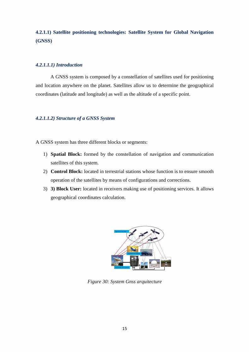
A GNSS system has three different blocks or segments:
1) Spatial Block: formed by the constellation of navigation and communication
satellites of this system.
2) Control Block: located in terrestrial stations whose function is to ensure smooth
operation of the satellites by means of configurations and corrections.
3) 3) Block User: located in receivers making use of positioning services. It allows
geographical coordinates calculation.
Figure 30: System Gnss arquitecture
16
4.2.1.1.3) Basic functioning of a GNSS system
Satellite radio-navigation functioning is based on obtaining an Earth surface
position, through calculation of distance among that position and at least three satellites
that are set in known location.
Satellites transmit synchronization signals containing their position and also the
time those signals where transmitted. To guarantee right synchronization, all the satellites
of the constellation use the same atomic clock.
The receiver is capable of calculating the elapsed time since the synchronization
signal was transmitted for each satellite thanks to an internal watch. By obtaining the
“signal flight time” of each constellation satellite the receiver position is defined.
To guarantee adequate accuracy and features, some parameters must be taken into account
such as number of satellites, their visibility and the number to select.
4.2.1.1.4) GPS System
The global positioning system is currently the only GNSS system providing whole
planet coverage. It was created and developed by USA Defence Department to determine
positions on the globe. It consists of a 24-satellite constellation orbiting to 20.200 km of
height with synchronized trajectories in a way that cover the entire Earth surface.
When a receiver need to know its position, it connects automatically to at least
four network satellites which send back their synchronization signals. By means of these
signals, the receiver device synchronizes the GPS clock and calculates the time needed
for the signals from the satellites to arrive to the device. Once the elapsed time is
calculated, it is obtained the distance of each satellite from the measured point. As the
satellites positions are known, the receiver is fully located.
As seen in the features of most analysed devices in the state of the art section,
outdoor location is assured by implementing a GPS receiver in those devices.
17
However, two factors must be taken into account if this technology is intended to be
used in the prototype:
1) To assure a device positioning, it is necessary to have direct sight with the
satellites. This way, adequate accuracy is obtained in outdoor environments, but
it can be an ineffective technology if the device is inside a building or structure
blocking correct reception of synchronization signals.
2) GNSS systems high power usage. During the entire connection and time
measurement as well as time and distance calculations s among satellites and the
receiver, it must remain connected to keep synchronization. This connection is
currently done at low speed causing high battery consumption.
This two factors may have two clear disadvantages in comparison with alternative
positioning systems because the goal is to guarantee indoor coverage as much as outdoor
coverage considering that due to the small size of the device, a low capacity battery will
be used.
4.2.1.2) Location technology provided by network operator:Global system for mobile
communications (GSM)
4.2.1.2.1) Introduction
GSM is a communication system for digital mobile telephony. GSM services
provide connection via a phone with other devices, allowing communication among them.
It functioning is based on dividing up available frequencies spectrum. Each operator is
assigned a delimited bandwidth which has all frequencies available to use.

18
4.2.1.2.2) GSM network simplified architecture
Following, there will be described the planning and key elements of a GSM
network in order to observe some operation differences in comparison with satellite
technologies and to understand the architecture used by mobile networks:
BS-Base Station
BSC- Base Station Controller
Some BS + BSC – Base Station Subsystem
MSC – Mobile Switching Centre
NSS – Network and switching System
HLR- Home Location Register
VLR – Visitor Location Register
Figure 31: GSM System Architecture
In bandwidth terms, it would be non-viable the usage of a single aerial. A GSM
network performs territorial separation thus obtaining several areas called cells. Each cell
contains an aerial, a BS that guarantees coverage in all cell surface.
Adjoining cells use distinct frequencies to avoid interference among them.
However, to seize available bandwidth effectively, reuse of frequencies in non-adjoining
cells is allowed.
19
The BSC in each BS acts as a proxy between the mobile network and the user
while managing power among terminals and BS and dividing up available frequencies.
A configured BS collection by using a BSC make a BSS up which provides a link
between a user terminal and a GSM system’s network main layer.
Obviously, a user can move between cells without losing the connection. This
action is managed by a BSC and it is called Handover.
A BSC notifies the MSCs of involved cells (the cell to be left and the cell to be
entered) and a terminal, to make the change from a BS to another.
A NSS allows call routing and data storage. Therefore it allows connection and
transmissions required by a call.
A MSC is responsible for directing calls by using a BSC and the BS of the
customer receiving a call.
The last elements are two registers:
-First, the HLR stores if a user belonging to a network is online or not, his available
services and other features. If a user receives a call, the MSC polls the corresponding
HLR for the terminal status of the number receiving the call and routes the call in case it
is available.
-Second, the VLR contains subscription types and locations in a network of all active
users, in that network segment, when a call is happening. If a user is registered in a
network, the VLR contacts the user’s HLR and verifies if he can make calls according to
his subscription.
Although the described network it is strictly not implementing a positioning
technology, it is appropriate to describe its architecture to have some knowledge about
how it operates so that it could be used to get the position of an element connected to a
network.
20
4.2.1.3) Positioning using a GSM network
By using a GSM network, a surface partition into cells is made thus assuring
coverage inside each of them. Since the position of all BS cells is known, it is easonable
to think that by using the mobile network it could be determined the position of a terminal
in a more or less accurate way.
There are two different methods provided by mobile networks that allow to locate a
device. Following, the most important ones are briefly described:
a) Cell-ID:
This first technique is the simplest of all. It uses location by cell. Each cell has an
identification number to be distinguished from others. Therefore, when a terminal is
connected to a BS, its position is determined by a cell area.
In other words, if the BS connected to the terminal is known then the area in which it
is located will be also known, as it is under the same coverage area.
The accuracy of this algorithm varies as cell sizes do, depending on cell radius. So, in
urban environments with high population density, cell radii are 150-250 meters long,
providing a quite adequate accuracy for location systems. However, in rural
environments, there can be found cells of several kilometres in length. In these cases, the
accuracy offered by this method would be quite ineffective.
a) E-OTD (Enhanced Observed Time Difference):
This method requires synchronization among the different BSs and its operation is
based on measuring the time a signal takes from the terminal to another BSs. Thanks to
the difference of these times to each BS, the position of the terminal is estimated.
The accuracy of this method comprises a distance from 50 to 200 meters.
a) AoA (Angle of Arrival)
Using this method, the terminal position is calculated thanks to the signal angle during
arrival to the BS aerial. At least, it is needed 2 BSs to get proper accuracy.
The main inconvenient of location by means of AoA is the need of equipping aerials
with special receivers and additional equipment thus raising costs.
21
a) RSS (Received Signal Strength)
The last algorithm to be presented considers the strength of received signal and works
for one BS as well as for many of them.
From the known BS position, by measuring the strength of the signal receiving from
the terminal and knowing the propagation losses in open space, it can be estimated the
distance from the BS to the terminal.
Considering a BS, the estimation defines a ring inside the cell with all points matching
the level of signal measured.
If the method is applied using various BSs, the intersections among those define the
terminal position.
The choice of the technique to be used is defined by a network, being totally
transparent for users.
There are networks that implement some of these techniques while the choice of one
of them is defined by several factors: urban or rural zone, quantity of obstacles in a zone,
types of antenna; etc.
One of the main advantages of location by using a mobile network is its robustness.
Thus in almost every place on the planet there is an operational mobile network that
assures coverage for its customers. So, a user location is guaranteed as long as he has
coverage.
Making a comparison with satellite system, it is observed the following two facts:
- Despite it offers lower accuracy than satellite systems, the use of mobile network
can be helpful in urban zones with very high population density or high number
of obstacles, making connection to satellites difficult.
- Both technologies require power consumption, but the use of a mobile network
reduces greatly connection time and battery consumption in comparison with
satellite connection.
Finally, it will be mentioned an extension of GSM networks. Networks using the
following service allow location via one or more of the mentioned methods.
22
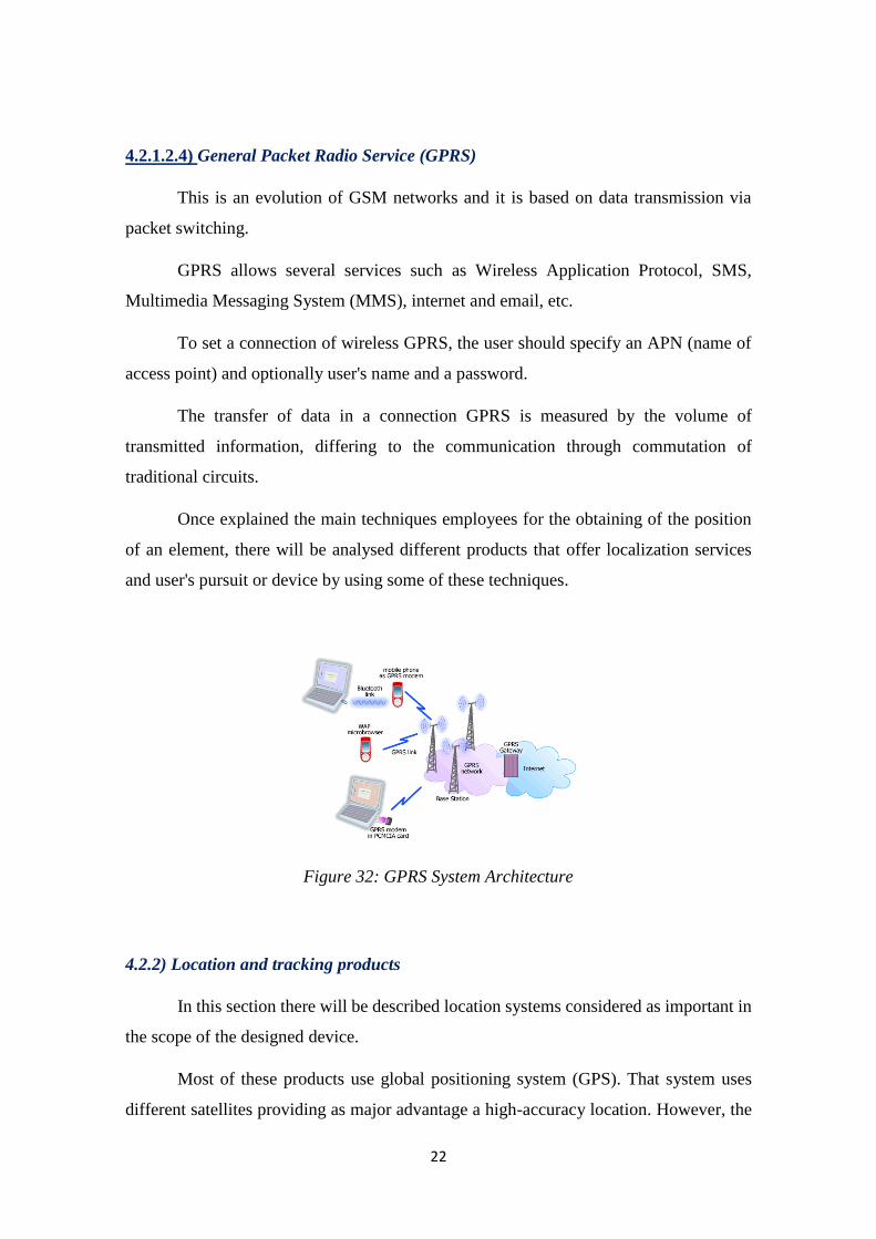
4.2.1.2.4) General Packet Radio Service (GPRS)
This is an evolution of GSM networks and it is based on data transmission via
packet switching.
GPRS allows several services such as Wireless Application Protocol, SMS,
Multimedia Messaging System (MMS), internet and email, etc.
To set a connection of wireless GPRS, the user should specify an APN (name of
access point) and optionally user's name and a password.
The transfer of data in a connection GPRS is measured by the volume of
transmitted information, differing to the communication through commutation of
traditional circuits.
Once explained the main techniques employees for the obtaining of the position
of an element, there will be analysed different products that offer localization services
and user's pursuit or device by using some of these techniques.
Figure 32: GPRS System Architecture
4.2.2) Location and tracking products
In this section there will be described location systems considered as important in
the scope of the designed device.
Most of these products use global positioning system (GPS). That system uses
different satellites providing as major advantage a high-accuracy location. However, the
23
main disadvantage that could affect the satellite technology for this project is energy
consumption.
Next, there are outlined the main products of location/tracking systems:
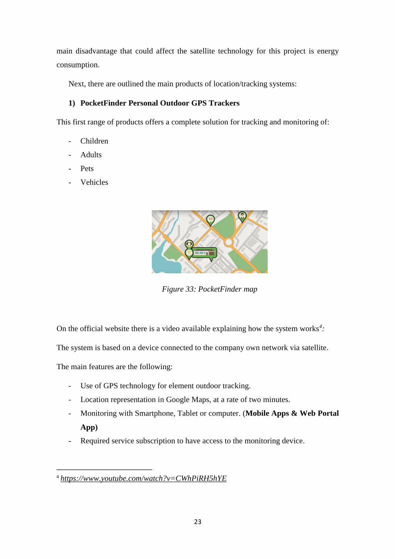
1) PocketFinder Personal Outdoor GPS Trackers
This first range of products offers a complete solution for tracking and monitoring of:
- Children
- Adults
- Pets
- Vehicles
Figure 33: PocketFinder map
On the official website there is a video available explaining how the system works4:
The system is based on a device connected to the company own network via satellite.
The main features are the following:
- Use of GPS technology for element outdoor tracking.
- Location representation in Google Maps, at a rate of two minutes.
- Monitoring with Smartphone, Tablet or computer. (Mobile Apps & Web Portal
App)
- Required service subscription to have access to the monitoring device.
4 https://www.youtube.com/watch?v=CWhPiRH5hYE
24
- Alarm system configured by the user (vehicle speeding, entering and leaving
defined zone).
- Alarm notifications via SMS, email and popup notifications in mobile app.
- Device motion logs with 60-days duration.
- Small-size design, rechargeable and easy to install (inside a pocket or pinned to
any garment or accessories).
- Power-saving system (device active only when in motion).
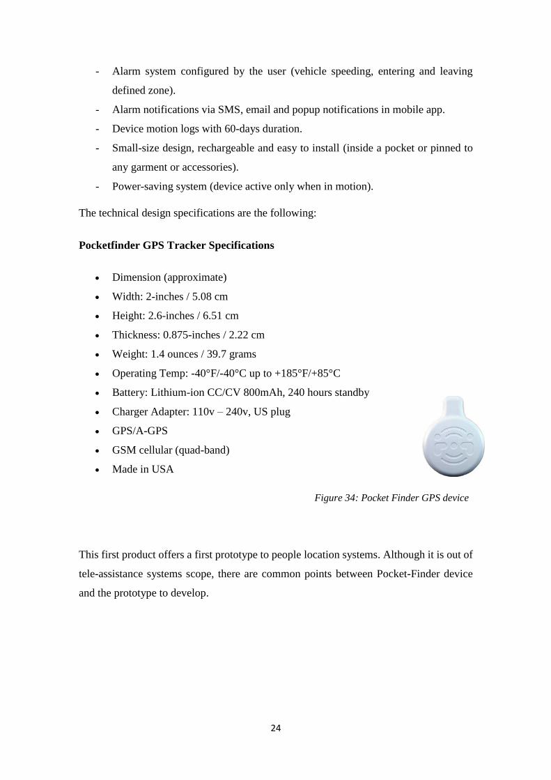
The technical design specifications are the following:
Pocketfinder GPS Tracker Specifications
Dimension (approximate)
Width: 2-inches / 5.08 cm
Height: 2.6-inches / 6.51 cm
Thickness: 0.875-inches / 2.22 cm
Weight: 1.4 ounces / 39.7 grams
Operating Temp: -40°F/-40°C up to +185°F/+85°C
Battery: Lithium-ion CC/CV 800mAh, 240 hours standby
Charger Adapter: 110v – 240v, US plug
GPS/A-GPS
GSM cellular (quad-band)
Made in USA
This first product offers a first prototype to people location systems. Although it is out of
tele-assistance systems scope, there are common points between Pocket-Finder device
and the prototype to develop.
Figure 34: Pocket Finder GPS device
25
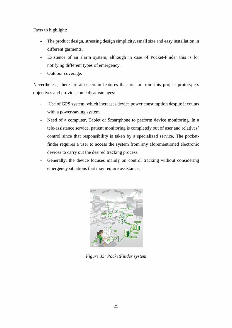
Facts to highlight:
- The product design, stressing design simplicity, small size and easy installation in
different garments.
- Existence of an alarm system, although in case of Pocket-Finder this is for
notifying different types of emergency.
- Outdoor coverage.
Nevertheless, there are also certain features that are far from this project prototype´s
objectives and provide some disadvantages:
- Use of GPS system, which increases device power consumption despite it counts
with a power-saving system.
- Need of a computer, Tablet or Smartphone to perform device monitoring. In a
tele-assistance service, patient monitoring is completely out of user and relatives’
control since that responsibility is taken by a specialized service. The pocket-
finder requires a user to access the system from any aforementioned electronic
devices to carry out the desired tracking process.
- Generally, the device focuses mainly on control tracking without considering
emergency situations that may require assistance.
Figure 35: PocketFinder system

26
2) GPS SmartSoles
This device has a significant shift in design compared to the previous one.
In this case, the device is incorporated inside a shoes insole, making its use seamless
for the user except during recharge.
Figure 36: SmartSole design
Leaving design aside, this tracking system is similar to previous one, however its
operation is simpler than Pocket-finder’s:
-It is also characterized as a system that provides outdoor coverage using a satellite system
and requires a subscription to a mobile data plan to access the service.
-Once again, monitoring is performed by means of a computer, Tablet or Smartphone
(with a specific mobile application) and will be carried out by the user or another person.
-It allows to register a zone that will define an alarm system that will be activated when
the user enters or leaves it.
-In power terms, the system can be recharged wirelessly but has no added system to
reduce satellite services consumption.
Figure 37: Smartsole logo

27
In comparison with Pocket-finder, there remains the same advantages (outdoor
coverage, design) as well as the same disadvantages (high power consumption,
Smartphone or computer needed).
The most important advantage of GPS Smartsole solution is its design, which is
far better than the previous device, that is, it is more comfortable to have it inside the
shoes insole than in an external element that must be pinned in some garment or
accessory.
This new design can be useful to define future lines if the main objective is increasing
ease and seamless usage for the user.
3) iTraq: The Cellular Tracking Device
This communication system offers a new shift in design as well as a new location
algorithm not based on satellite communication.
This is the main reason that led us to consider its analysis as especially important.
This time, design is based on a plastic card with a hole that allows it to be pinned to
garments or elements.
Figure 38: iTraq design
In comparison with previous systems, the most important difference lies in the
algorithm that has been used to locate the card.
While the rest of tracking systems use GPS technology, iTraq has a standard
functionality by using the mobile network, or what is the same, GPRS technology,
providing coverage anywhere in the world where there is phone signal.
It also offers an emergency service as added value when rapid and accurate card
location is required, which activates GPS system to provide more precise location in case
of emergency.
28
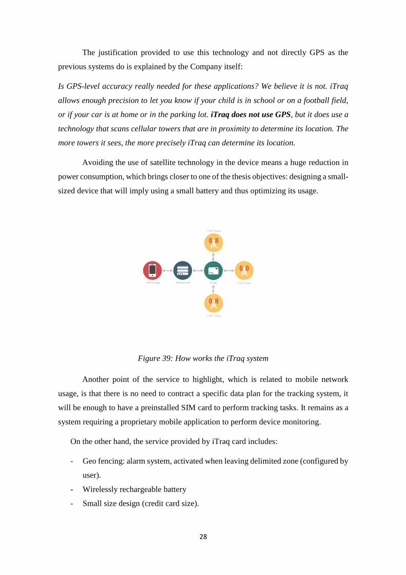
The justification provided to use this technology and not directly GPS as the
previous systems do is explained by the Company itself:
Is GPS-level accuracy really needed for these applications? We believe it is not. iTraq
allows enough precision to let you know if your child is in school or on a football field,
or if your car is at home or in the parking lot. iTraq does not use GPS, but it does use a
technology that scans cellular towers that are in proximity to determine its location. The
more towers it sees, the more precisely iTraq can determine its location.
Avoiding the use of satellite technology in the device means a huge reduction in
power consumption, which brings closer to one of the thesis objectives: designing a small-
sized device that will imply using a small battery and thus optimizing its usage.
Figure 39: How works the iTraq system
Another point of the service to highlight, which is related to mobile network
usage, is that there is no need to contract a specific data plan for the tracking system, it
will be enough to have a preinstalled SIM card to perform tracking tasks. It remains as a
system requiring a proprietary mobile application to perform device monitoring.
On the other hand, the service provided by iTraq card includes:
- Geo fencing: alarm system, activated when leaving delimited zone (configured by
user).
- Wirelessly rechargeable battery
- Small size design (credit card size).

29
Taking into account the proposed prototype, the approach of iTraq device turns out to
be very interesting since it offers the possibility of locating an element using a technology
different from any other satellite technology.
Figure 40: iTraq main characteristics
4) Safe Link GPS:
The next range of products for people location has most of the described features so
far including just one significant novelty in one of the models: the introduction of a system
that activates an alarm in case of a possible fall detection.
The main features of the several devices provided are:
- Allow monitoring from computer or mobile device.
- Notifications system (Virtual Fence, SOS, low battery) via SMS.
- Real-time tracking of a user.
The three products offered in Safe-Link range are:
1) 2G Watch Tracker:
-Metallic watch with sleek design enabling location.
-Outdoor coverage by using GPS and complementary system for indoor coverage
using wireless networks.
-Allows continuous tracking calculating the position every two minutes.

30
-Implements its own Geofencing system with alarm system.
Figure 41: Safe Link monitoring system
2) 2G Personal Tracker: rectangular small-sized plastic device that offers the
same features as the watch. It has a personal tracker that keeps the connection
in case of failure of the other servers.
3) 3G Tracker: it is the most complete product in the range because it includes
all services described by previous systems. It also includes:
- Implementation of a voice channel enabling the device to make calls to one or
more mobile terminals in an emergency.
- Fall detection system, that allows when activated to send an alarm to the different
pre-configured mobile numbers.
Regarding the design, no important new features are provided over previous solutions
except related to the watch. Once again, there are proposed small size devices that can be
placed on a belt, a shirt, or inside the pocket or any bag or suitcase.
The two additional features offered by the 3G Tracker are closer to a possible system
of tele-assistance, although the alarm system is intended to be controlled by user’s
relatives or acquaintances and do not requires any specialized service that can offer
assistance if required.
The fall detection plays an important role in any assistance system intended for elderly
people since the possibility of an emergency voice channel greatly reduces the time for
reaction.
31
5) Accuware products:
This tracking products range, even though it has no important novelties in comparison
with the previous solutions, offers a well-suited location service using cellular technology
(cell ID) and mobile networks (Wi-Fi), over mobile devices.
Unlike previous products, an external element is not required to perform the tracking
and monitoring. Accuware allows the execution of all functions on the same user´s
Smartphone without any other element.
Despite that, there is a range of recommended products that allows a more accurate
location which are briefly described below:
a) Accuware Smart Tag:
- Designed for people and elements that require indoor coverage.
- Radio wifi, motion sensor and rechargeable battery.
- Wi-Fi signal continuous tracking, data storage service in the cloud.
- It allows indoor tracking with a tolerance of two meters.
- It has programmable button to define an alert system.
b) Combo Tags:
- Designed for people and elements that require global coverage (outdoor + indoor).
- Provided with wireless technology, GSM and GPS, motion sensor and
rechargeable battery.
- Wi-Fi signal continuous tracking, data storage service in the cloud.
- Average accuracy:
Indoor: 2 meters.
Urban areas: 30 meters.
- Requires a mobile data plan for outdoor location.
These devices are not strictly necessary to access the different services since with user
Smartphone or smart watch, the desired location can be obtained, due to the
implementation of Accuware software.
The different services are divided into four parts:
- Tracking: location is allowed in both outdoor and inside a building, depending on
the device used.

32
- Navigation: only indoor environment; specially designed to guide user in large
buildings.
- Monitoring: provides recording and possible control of the motion and tracking
of a user.
- Proximity: using wireless devices, different events will be handled when a user
moves towards or away from a point of interest.
Example: automatic check-in in a hotel when the user enters with his Accuware
device.
It is observed that the presented range of products offers a complete solution that
attends to new services such as indoor navigation or management of events according to
user proximity.
6) Geo.Band
This system is defined as the smallest monitoring system in the market with a size of
40x41x13'5mm, waterproof. It provides outdoor coverage in about 133 different
countries. The design is rectangular with a screen, and can be worn as a watch or key ring.
Figure 42: Geo band products
Geo.Band has all the features seen so far in a typical monitoring system:
- Notification/alarm system activated in case of:
Falls or accidents
Mobility overnight
Prolonged immobility during the day.
SOS button is pressed.
33
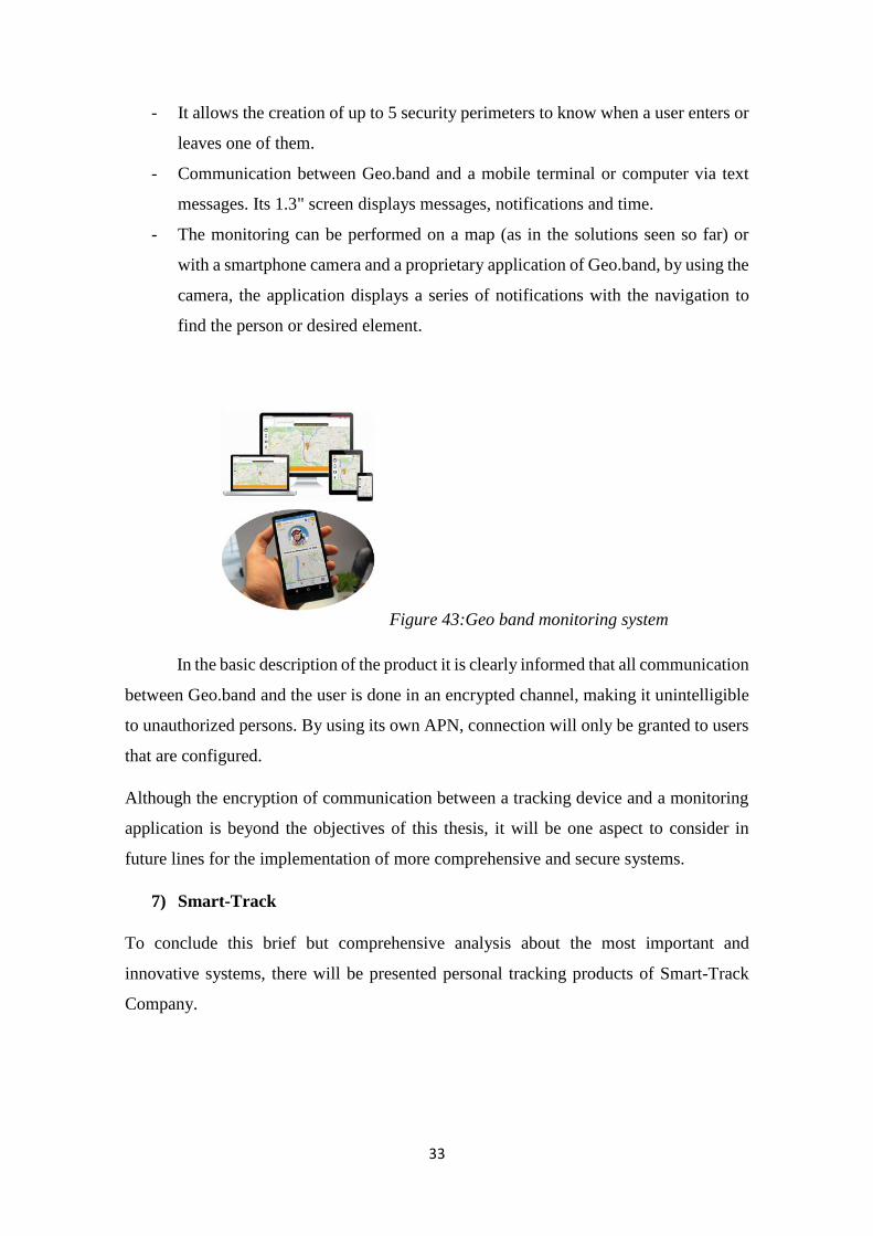
- It allows the creation of up to 5 security perimeters to know when a user enters or
leaves one of them.
- Communication between Geo.band and a mobile terminal or computer via text
messages. Its 1.3" screen displays messages, notifications and time.
- The monitoring can be performed on a map (as in the solutions seen so far) or
with a smartphone camera and a proprietary application of Geo.band, by using the
camera, the application displays a series of notifications with the navigation to
find the person or desired element.
Figure 43:Geo band monitoring system
In the basic description of the product it is clearly informed that all communication
between Geo.band and the user is done in an encrypted channel, making it unintelligible
to unauthorized persons. By using its own APN, connection will only be granted to users
that are configured.
Although the encryption of communication between a tracking device and a monitoring
application is beyond the objectives of this thesis, it will be one aspect to consider in
future lines for the implementation of more comprehensive and secure systems.
7) Smart-Track
To conclude this brief but comprehensive analysis about the most important and
innovative systems, there will be presented personal tracking products of Smart-Track
Company.
34
These products, apart from combining the features already seen in previous devices, offer
new services that may be of interest either for the prototype of this thesis or for future
designs.
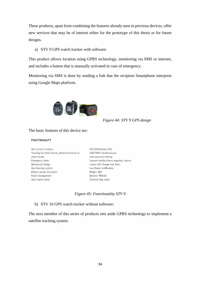
a) STV 9 GPS watch tracker with software:
This product allows location using GPRS technology, monitoring via SMS or internet,
and includes a button that is manually activated in case of emergency.
Monitoring via SMS is done by sending a link that the recipient Smartphone interprets
using Google Maps platform.
Figure 44: STV 9 GPS design
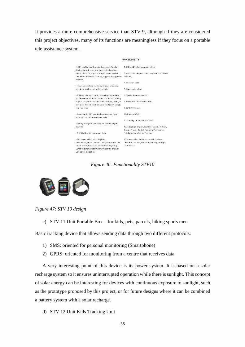
The basic features of this device are:
Figure 45: Functionality STV 9
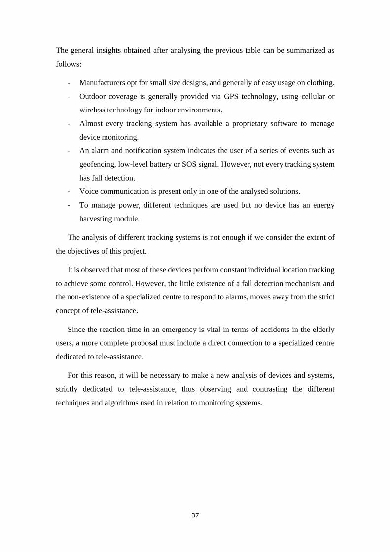
b) STV 10 GPS watch tracker without software:
The next member of this series of products sets aside GPRS technology to implement a
satellite tracking system.
35
It provides a more comprehensive service than STV 9, although if they are considered
this project objectives, many of its functions are meaningless if they focus on a portable
tele-assistance system.
Figure 46: Functionality STV10
Figure 47: STV 10 design
c) STV 11 Unit Portable Box – for kids, pets, parcels, hiking sports men
Basic tracking device that allows sending data through two different protocols:
1) SMS: oriented for personal monitoring (Smartphone)
2) GPRS: oriented for monitoring from a centre that receives data.
A very interesting point of this device is its power system. It is based on a solar
recharge system so it ensures uninterrupted operation while there is sunlight. This concept
of solar energy can be interesting for devices with continuous exposure to sunlight, such
as the prototype proposed by this project, or for future designs where it can be combined
a battery system with a solar recharge.
d) STV 12 Unit Kids Tracking Unit

36
This last model is a simplification of the previous models, oriented to children and
which has all the basic functions already stated by previous location systems.
After analysing various tracking systems, they are identified their most common features,
the usually used technologies and the extra features implemented by each one of the
products.
The main features of the described elements are compared regarding the objectives for
designing a prototype of this thesis are specified by the next table:
Pocket-
Finder
GPS
Smartsole
iTraq Safe-Link
(3G
Tracker)
Accuware Geo.Band Smart-Track
Design Key ring,
pendant
Shoes
insole
Plastic
card
Rectangular
device
(pager)
Smartphone,
watch or pager
Watch,
key ring
Watch, bracelet
Coverage Outdoor Outdoor Indoor /
Outdoor
Outdoor Indoor/Outdoor Outdoor Indoor/Outdoor
Used
technology
GPS GPS GPRS
/GPS
GPS GPRS/
GPS/
Wifi
GPS GPRS
Additional
software
Yes Yes Yes Yes Yes Yes No
Notifications&
Alarms
Yes Yes Yes Yes Yes Yes Yes
Fall detection No No No Yes No Yes No
Voice
communication
No No No Yes No No No
Power
efficiency
Only
active in
motion
No No No No No Solar energy
recharge in one
of the device
37
The general insights obtained after analysing the previous table can be summarized as
follows:
- Manufacturers opt for small size designs, and generally of easy usage on clothing.
- Outdoor coverage is generally provided via GPS technology, using cellular or
wireless technology for indoor environments.
- Almost every tracking system has available a proprietary software to manage
device monitoring.
- An alarm and notification system indicates the user of a series of events such as
geofencing, low-level battery or SOS signal. However, not every tracking system
has fall detection.
- Voice communication is present only in one of the analysed solutions.
- To manage power, different techniques are used but no device has an energy
harvesting module.
The analysis of different tracking systems is not enough if we consider the extent of
the objectives of this project.
It is observed that most of these devices perform constant individual location tracking
to achieve some control. However, the little existence of a fall detection mechanism and
the non-existence of a specialized centre to respond to alarms, moves away from the strict
concept of tele-assistance.
Since the reaction time in an emergency is vital in terms of accidents in the elderly
users, a more complete proposal must include a direct connection to a specialized centre
dedicated to tele-assistance.
For this reason, it will be necessary to make a new analysis of devices and systems,
strictly dedicated to tele-assistance, thus observing and contrasting the different
techniques and algorithms used in relation to monitoring systems.
38
4.2.3) Tele-assistance products
Making a first contact with the state of the art of tele-assistance systems, there will be
analysed different devices that allow notification and assistance in case of emergency and
afterward moving to a brief description of some complete tele-assistance systems that are
used nowadays.
The following devices differ from tracking systems in their main objective.
These systems are intended for people who may need help in certain circumstances.
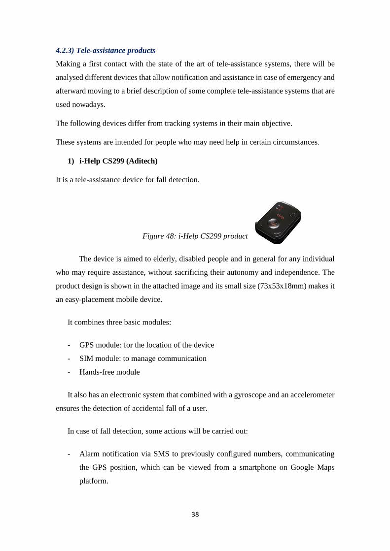
1) i-Help CS299 (Aditech)
It is a tele-assistance device for fall detection.
Figure 48: i-Help CS299 product
The device is aimed to elderly, disabled people and in general for any individual
who may require assistance, without sacrificing their autonomy and independence. The
product design is shown in the attached image and its small size (73x53x18mm) makes it
an easy-placement mobile device.
It combines three basic modules:
- GPS module: for the location of the device
- SIM module: to manage communication
- Hands-free module
It also has an electronic system that combined with a gyroscope and an accelerometer
ensures the detection of accidental fall of a user.
In case of fall detection, some actions will be carried out:
- Alarm notification via SMS to previously configured numbers, communicating
the GPS position, which can be viewed from a smartphone on Google Maps
platform.
39
- - Emission of an audible alarm by the device, requesting help in proximity to the
user.
The fall alarm will automatically be deactivated if the user is reinstated autonomously
or deactivates the alarm manually.
In addition to fall detection, the person using the device i-help could make a phone
call by pressing the button of the device to notify any emergency or need. The hands-free
module facilitates communication in any call made via the device.
By using proprietary mobile application, the management and monitoring of the
device is possible.
This first device offers a tele-assistance service, but again, there is no specialized
service that can assist the patient in an emergency. The assistance shall come from family
members or people owning programmed telephone numbers into the device, making it
less effective depending on a case basis.
It has similar features to monitoring systems analysed, such as location using GPS
technology or alarm notification via SMS.
However, while previous systems focus on a control and monitoring device, the main
objective of i-help is the capability to offer assistance to a person in case of a fall or
emergency.
2) Mindme:
The alarm devices "Mind Me" offer a simple and rapid solution to any type of
emergency.
With small size design and easy placement -key ring, in a backpack, attached to the
pants etc. - is a very interesting option for people who spend a lot of time alone, or can
be found in risky situations without having nearby assistance.
The most important novelty compared to most of the analysed devices is the existence
of a specialized centre that responds to the alarm signal.
40
So far, most solutions sent alarm signals to previously determined numbers although
they did not need to know how to respond to an emergency.
The specialized centre is comprised of a team of people trained to manage and make
decisions in cases of emergency, reducing waiting and response time when facing an
adverse event.
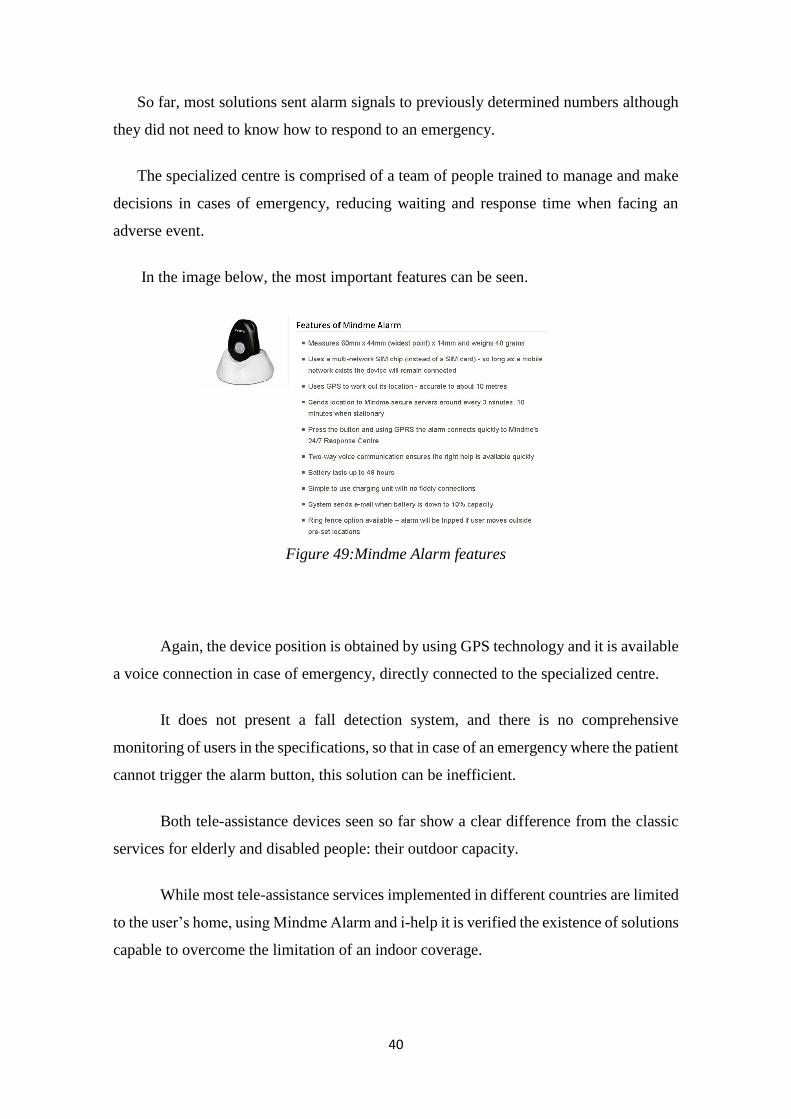
In the image below, the most important features can be seen.
Figure 49:Mindme Alarm features
Again, the device position is obtained by using GPS technology and it is available
a voice connection in case of emergency, directly connected to the specialized centre.
It does not present a fall detection system, and there is no comprehensive
monitoring of users in the specifications, so that in case of an emergency where the patient
cannot trigger the alarm button, this solution can be inefficient.
Both tele-assistance devices seen so far show a clear difference from the classic
services for elderly and disabled people: their outdoor capacity.
While most tele-assistance services implemented in different countries are limited
to the user’s home, using Mindme Alarm and i-help it is verified the existence of solutions
capable to overcome the limitation of an indoor coverage.
41
Classic tele-assistance services, as already explained in the introduction consist of
two key elements: the transmitter device, usually a watch or pendant, and the terminal
connected to the telephone network.
The terminal is connected to a specialized service generally during twenty-four
hours, that could track the patient or simply to act quickly in case of emergency.
For example, there are companies that make regular calls to patients in order to
gain some control over them or study patients routines to detect any event that breaks the
routine of the user and may originate some risk for them.
The transmitter device is usually small-sized and easy to use for avoiding being a
burden to users.
There are a lot of companies offering tele-assistance solutions. Among them there
are some companies that are located in Spain:
-SARquavitae: allows outdoor location using a mobile device and GPS technology.
-PROSEGUR alarms: with implementation of fall and warning system to medical
services.
-Atenzia: with direct connection to emergency services and permanent connection.
After defining the basic structure of a complete system of tele-assisstance, the following
device to analyse is the product Adamo, by Caretek Company, which is the basis or
starting point for the research carried out in this project.
3) Adamo (CareTek):
It meets the requirement of providing autonomy and independence inside home to
elderly people or people with certain disabilities.
Figure 50:Adamo logo
42
Adamo is shaped like a normal watch, light and practical. It accompanies the
person without causing any discomfort. It is composed by waterproof materials that allow
its uninterrupted use even under the shower.
It has a sensor that determines whether the watch is being used by the person and
an individual monitoring is carried out if the pulse is detected, otherwise, the device only
emits safe radio waves set by default. Apart from this sensor, different internal watch
sensors are capable of detecting if the user is in motion or conversely remains motionless,
besides it detects body temperature and battery status. Each of these sensors is capable to
send alerts when abnormal parameters are detected.
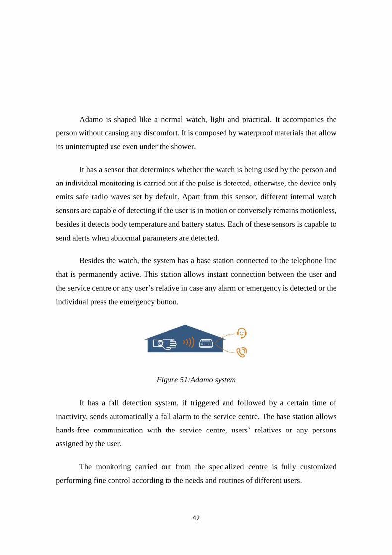
Besides the watch, the system has a base station connected to the telephone line
that is permanently active. This station allows instant connection between the user and
the service centre or any user’s relative in case any alarm or emergency is detected or the
individual press the emergency button.
Figure 51:Adamo system
It has a fall detection system, if triggered and followed by a certain time of
inactivity, sends automatically a fall alarm to the service centre. The base station allows
hands-free communication with the service centre, users’ relatives or any persons
assigned by the user.
The monitoring carried out from the specialized centre is fully customized
performing fine control according to the needs and routines of different users.
43
It does not implement any location system since the system is intended for home
use, but it uses an algorithm that detects whether the user is away or near the base station.
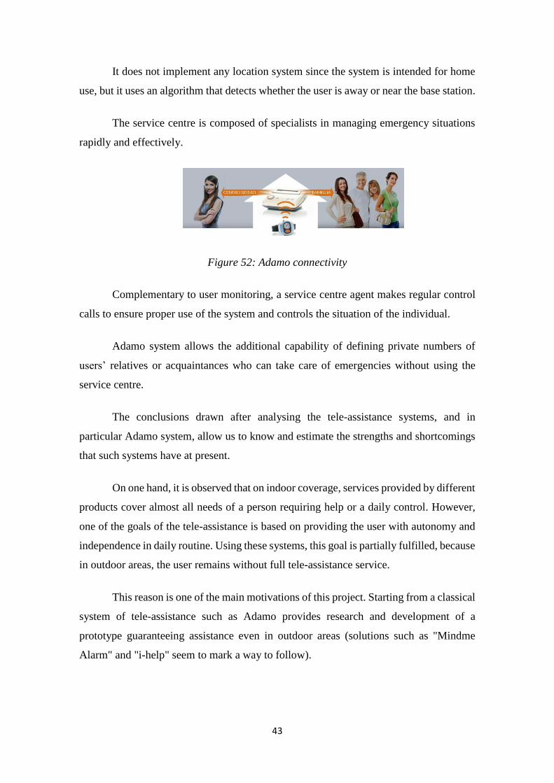
The service centre is composed of specialists in managing emergency situations
rapidly and effectively.
Figure 52: Adamo connectivity
Complementary to user monitoring, a service centre agent makes regular control
calls to ensure proper use of the system and controls the situation of the individual.
Adamo system allows the additional capability of defining private numbers of
users’ relatives or acquaintances who can take care of emergencies without using the
service centre.
The conclusions drawn after analysing the tele-assistance systems, and in
particular Adamo system, allow us to know and estimate the strengths and shortcomings
that such systems have at present.
On one hand, it is observed that on indoor coverage, services provided by different
products cover almost all needs of a person requiring help or a daily control. However,
one of the goals of the tele-assistance is based on providing the user with autonomy and
independence in daily routine. Using these systems, this goal is partially fulfilled, because
in outdoor areas, the user remains without full tele-assistance service.
This reason is one of the main motivations of this project. Starting from a classical
system of tele-assistance such as Adamo provides research and development of a
prototype guaranteeing assistance even in outdoor areas (solutions such as "Mindme
Alarm" and "i-help" seem to mark a way to follow).
44
If it is intended to offer a practical outdoor coverage, the need to remove the base
station arises, obtaining a compact device that can be introduced into daily routines in a
simple and transparent manner.
For this reason, power saving becomes especially important since the use of
batteries implies the device being bigger size. As the device is small size, there will be
necessary the efficient use of energy in order to ensure proper and practical autonomy in
real scenarios.
With the introduction of IOT (Internet of things) and in general, technology into
ever smaller size devices, one of the most interesting fields under study, offering a
possible improvement over the methodologies currently used, is called Energy
Harvesting.
This concept is based on obtaining energy from different sources, so that a
complementary source of energy is obtained, increasing autonomy without having to
affect device small size.
To finish this section, a brief theoretical study is performed regarding the main
techniques used in Energy Harvesting as well as checking development level of them.
Besides, possible future lines are defined to exploit power efficiency in wearable devices.
Besides, there will be mentioned in-market products which provide power saving to low
consumption systems.
4.2.4) Introduction to Energy Harvesting
4.2.4.1) EH fundaments
The concept of Energy Harvesting starts from energy gathering originated in
external sources, offering greater autonomy to different wireless systems.
Energy harvesters provide a very small amount of power for low-power
electronics. While the fuel input to the large-scale generation is usually costly (oil, coal,
etc.), the energy source for collectors is present as environmental fund and free. For
example, in urban areas there are a lot of electromagnetic energy in the environment due
to radio and television or the presence of large wind currents in certain areas etc.
45
By means of Energy Harvesting, efficiency is improved, in energy terms, as it
offers the capability to capture small amounts of energy from environmental sources
which would be lost by using other techniques.
It also enables the creation of new technologies and autonomous devices that can
work without cables. (Example: Wireless Sensors).
EH has the potential to replace the conventional battery system for electronic low-
power devices. By replacing the batteries, a more environment-friendly system is
developed since batteries are often composed of hazardous materials to health and
harmful to the environment and maintenance is cheapened as there is no need to replace
the batteries so often.
These energy techniques are applicable in different areas:
- Large scale systems, where a lot of untapped energy is lost. Example: Industrial
process where almost half the input energy is dissipated as heat. In this case, EH
could be an energy increase by capturing that dissipated energy.
- Wearable systems, which have a constant source of energy from natural sources
can provide great autonomy and economic maintenance without cables.
There is a lot of EH materials (ceramics, glass, polymers and composites) that are
currently being developed. The purpose of these materials is to capture small amounts of
energy that would otherwise be lost during industrial processes or simply processes
performed day after day.
These small amounts of energy that can be captured by EH come from various natural
sources. Depending from the source selected to obtain energy, it will be more appropriate
the use of materials which have certain specific properties.
46
Following, there will be presented the most significant materials and their possible
applications:
- Piezoelectric Materials:
Piezoelectricity is defined as the capability to obtain power from a specific pressure.
Piezoelectric materials accumulate electrical charge on a solid material as a result of
mechanical tension.
The movement of the human body, low frequency vibrations or acoustic noise are some
of the sources from which a piezoelectric material can collect energy.
Some examples are the following ones:
a) Remote control without the use of batteries: The force exerted when pressing a button
is enough to generate a signal.
b) Generation of energy using the vibrations generated by the steps of people in a train
station.
c) Maintenance of a wearable autonomous device intended for running, collecting energy
through the vibration of the shoes of the device user.
d) Sensors on vehicle wheels, allowing its monitoring and been capable of making
notifications on any screen or system.
Applications that use piezoelectricity techniques are at development state,
although there are some commercial devices.
There is a lot of literature and scientific studies regarding the efficiency and
performance waiting for piezoelectric materials.
Nowadays, it is difficult to make a comparison between piezoelectric devices
since there is no international acknowledgment to characterize and compare the efficiency
and performance of different devices. Each vendor offers its own features and studies,
highlighting the product offering thus hindering an objective and simple comparison for
interested users.
47
In wearable systems, where size and autonomy of the device is of vital importance,
piezoelectric materials will be a cornerstone for their evolution without having to give up
compact size.
- Thermoelectric materials:
The following materials exploit the temperature difference present in a thermoelectric
crystal when a heat source is applied on it. When this happens, the different parts of the
material are at different temperatures since a heat source has been applied to a part for
increasing the temperature. This difference causes a voltage across the crystal.
The potential applications of these materials require a constant heat source. So there
are different vehicles (cars, trucks) incorporating thermoelectric generators. When the
engines of these vehicles are in operation, the heat dissipated by them is captured by the
thermoelectric material, providing an additional source of energy.
Any heating system can incorporate thermoelectric materials. An example of it is a
radiator that takes advantage of the heat dissipated to indicate in a display the temperature
it is configured for.
Thermoelectric technology is considered one of the most promising technologies in
terms of energy efficiency in industrial processes where a large amount of energy is lost
as heat, for example the automotive or computer sector.
The behaviour of a thermoelectric material is defined by the thermoelectric merit
factor. There is an international competition to improve this factor. However, this
competition cannot be an absolute reference since there is no an undeniable
thermoelectric material used by different vendors. Nevertheless, by using thermoelectric
materials a fairly accurate comparison can be made among different products unlike what
happened with piezoelectric materials.
Generally, applications of thermoelectric materials were limited due to the small
conversion efficiency since very little energy captured. However, with the introduction
of nanostructured thermoelectric materials, it has led to a remarkable improvement of
thermoelectric properties.
48
Because of the need to improve energy efficiency through the recovery of residual
heat present in the different processes, studies and progress on thermoelectric materials
increase progressively.
- Pyroelectric Materials
The pyro-electrical effect converts a temperature change into an electrical current or
voltage. If there is no temperature change on the material, no energy is generated, thus
these materials require variable input sources over time causing different temperatures in
the material.
Although pyro-electrical effect offers the advantage of allowing very high
temperatures, regarding thermoelectric materials it is still at a remote stage far away of
EH applications marketing. However, even at this early stage of development, the pyro-
electrical effect appears to be more effective than other energy harvesting techniques, but
only under specific conditions.
Power generation requires a temporary variation in temperature every few seconds,
to find an input source that can provide such variation is an expensive task outside a
laboratory.
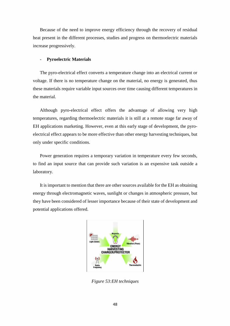
It is important to mention that there are other sources available for the EH as obtaining
energy through electromagnetic waves, sunlight or changes in atmospheric pressure, but
they have been considered of lesser importance because of their state of development and
potential applications offered.
Figure 53:EH techniques

49
4.2.4.2) Future lines, Research and development
The European Commission (EC) has identified sustainable energy supply as one
of the major goals of modern society.
In accordance with this goal, which is promoting a major European campaign
funding for R & D (research and development on the generation, use and energy
efficiency).
A section of this campaign focuses on research and development of technologies
capable of capturing energy, which directly refers to EH.
The main obstacle to the development of EH technologies comes when
characterizing and comparing different devices. Internationally and recognized
measurement standards capable of ensuring a rigorous and accurate characterization of
EH devices in terms of energy efficiency or consumption become especially needed.
The project named "The Metrology for Energy Harvesting", funded by the
European Metrology Research Programme, has as one of its objectives to use a
standardized approach that supports the different EH systems. The main areas addressed
by the project are: efficiency, scalability, manufacturing and cost.
The Metrology for Energy Harvesting is a collaborative project of three years, which
brings together experts from different countries and is aimed to different objectives:
- To address research gaps identified by the industry.
- To encourage increased collaboration between industry and the European research
community.
- To reduce costs.
- To maximize energy efficiency.
- To improve sustainability in industrial processes and products.
The project provides the methodological framework, technical capacity and scientific
knowledge necessary for the development of EH.
50
“When you can measure what you are speaking about, and express it in numbers, you
know something about it; but when you cannot measure it, when you cannot express it
in numbers… you have scarcely, in your thoughts, advanced it to the stage of
science”(1)
Energy sources considered due to their interest for this project are largely
unexploited sources of environmental energy, resulting from human activity and the
environment in the form of residual heat, motion and vibration.
The project has the support of seven national measurement institutes in Europe:
1. NPL (UK)
2. PTB (Germany)
3. LNE (France)
4. INRIM (Italy)
5. MIKES (Finland)
6. CMI (Czech Republic)
7. SIQ (Slovenia)
After defining the framework within the main techniques of EH are included, the
early stage of development can be considered. Currently, most of research focuses on
analysing new techniques, materials, and the need for international standards that allow
the marketing of different products.
Focusing again on the prototype developed in this project and its objectives, a
possible implementation of pyro-electrical and thermoelectric materials can be
considered meaningless.
On one hand, the device is placed on a user (watch) or hooked on a garment or
placed in a pocket or purse. In either case, there is no a source of sufficient and constant
heat to capture energy or a source generating a temperature that varies over time every
few seconds providing a constant flow of energy. However, the inclusion of piezoelectric
materials could make sense depending on the final design. For example, it could be taken
advantage of the movement and vibration from a shoe to generate energy.
51
To conclude the study of the state of the art of EH techniques, a brief market
survey can be developed starting with some EH modules available on the market, ending
with the description of several products and energy solutions that are offered by different
companies.
4.2.4.3) EH modules
There are several sensor vendors on the market, generally piezoelectric ones.
Thus, it is observed how companies such as "Linear Technology" or " Midé " offer some
variety of piezoelectric materials.
In the figures below different products offered by both companies can be seen:
In order to know the theoretical benefits of these devices, technical specifications
of LTC3588 device, which vendor is "Linear Technology, are listed below ".
This small module (less than a coin) allows energy capture by adding a
piezoelectric material and also using solar charging. The energy is stored in a capacitor
that is integrated on the chip.
It offers four possible output voltages of 1.8, 2.5, 3.3 and 3.6 V with a maximum
of 100 mA of output current.
Comparing technical specifications offered by different manufacturers, the
problem discussed above for piezoelectric modules is checked. Each provider offers
different features, a fact that causes some difficulty in comparing different devices.
Furthermore, there are different kits for studying EH, such as Energy Harvesting
Solution To Go from Silicon Labs company. This kit has a microcontroller with a full EH
module that includes piezoelectric capacity, solar charging and thermal charging through
a peltier panel.
52
The goal of these kits is usually the study of different EH techniques and the
analysis of results for future projects and applications.
4.2.4.4 )Products and EH projects
Finally, in order to set a first view of EH concept and the different possibilities it
offers, it will be describe several products that are part of the current market and which
implement EH technologies that have been analysed previously.
1) Ampy
The Ampy portable device consists of a battery that is capable of storing energy
collected directly through motion of the user.
It responds to the need to provide a power source for electronic devices of small size
-Smartphone, smartwatch, Tablet-, when these cannot be recharged via cable connected
to the current.
Ampy offers a complete solution for energy storage through wearer motion. Energy
capture is performed by inductors.
The device has different accessories for placement in different parts of the body or
clothing, so we can capture the greatest amount of motion in every situation, for instance
if it is tied to the ankle when the user is walking or running around town.
The more motion, the more energy stored by Ampy.
In the product specifications, it is indicated the battery capacity, 1800 mAh, and the
charge level achieved after one hour of standard activity:
- Up to one hour of battery in a Smartphone in normal use.
- Up to five hours of battery life, on a smartphone, in standby.
Up to 24 hours of use on a Smartwatch.
Thus, the device offers a solution in situations where a user requires battery for
any of his mobile devices and does not have an electrical power system to connect to.

53
Ampy functions as a traditional powerbank, being able to be charged to the electric
current. However, the ability to generate energy by performing routine activities is its
fundamental property.
Complementing the device, user activities monitoring is allowed by using a proprietary
mobile application. This way it is possible to analyse and check the energy generated each
day or while doing any activity.
Using this product, an additional energy source is available for an electronic device taking
advantage of EH techniques.
Figure 54:Ampy system
2) Sole Power
Next product is in a state of pre-marketing and is based on motion, the same principle
as the Ampy battery.
In this case, energy comes determined by user´s steps. Sole Power system consists of
a couple of shoe insoles, each connected to a rechargeable battery. These insoles exploit
heels impact onto ground when walking to produce energy which is stored in
aforementioned batteries.
When the user requires an additional source of energy or does not have a power supply
to connect to, he can connect his device to one of system batteries using a USB cable.

54
The batteries have a storage capacity of 300mAh each, and as specified in the
description, one hour walking with Sole Power insoles guarantee thirty minutes of
conversation using a mobile terminal, although, the amount of energy depends on the
speed, weight, activity and strength of the heels impact.
Figure 55:Sole power product
It also includes advice for people who need any power source at any time during their
daily activities.
3) WaTTup:
The WaTTup system developed by the company Energous Corporation, offers a
wireless solution for charging multiple electronic devices.
Its operation by using RF waves (radio frequency) allows electronic devices to store
energy wirelessly.
Figure 56:WaTTup charge system
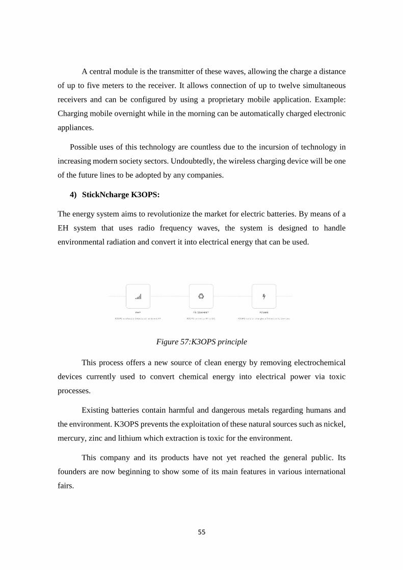
55
A central module is the transmitter of these waves, allowing the charge a distance
of up to five meters to the receiver. It allows connection of up to twelve simultaneous
receivers and can be configured by using a proprietary mobile application. Example:
Charging mobile overnight while in the morning can be automatically charged electronic
appliances.
Possible uses of this technology are countless due to the incursion of technology in
increasing modern society sectors. Undoubtedly, the wireless charging device will be one
of the future lines to be adopted by any companies.
4) StickNcharge K3OPS:
The energy system aims to revolutionize the market for electric batteries. By means of a
EH system that uses radio frequency waves, the system is designed to handle
environmental radiation and convert it into electrical energy that can be used.
Figure 57:K3OPS principle
This process offers a new source of clean energy by removing electrochemical
devices currently used to convert chemical energy into electrical power via toxic
processes.
Existing batteries contain harmful and dangerous metals regarding humans and
the environment. K3OPS prevents the exploitation of these natural sources such as nickel,
mercury, zinc and lithium which extraction is toxic for the environment.
This company and its products have not yet reached the general public. Its
founders are now beginning to show some of its main features in various international
fairs.
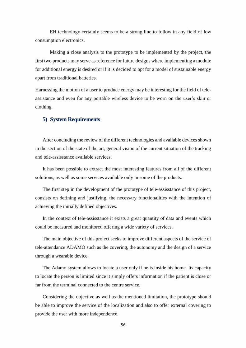
56
EH technology certainly seems to be a strong line to follow in any field of low
consumption electronics.
Making a close analysis to the prototype to be implemented by the project, the
first two products may serve as reference for future designs where implementing a module
for additional energy is desired or if it is decided to opt for a model of sustainable energy
apart from traditional batteries.
Harnessing the motion of a user to produce energy may be interesting for the field of tele-
assistance and even for any portable wireless device to be worn on the user’s skin or
clothing.
5) System Requirements
After concluding the review of the different technologies and available devices shown
in the section of the state of the art, general vision of the current situation of the tracking
and tele-assisstance available services.
It has been possible to extract the most interesting features from all of the different
solutions, as well as some services available only in some of the products.
The first step in the development of the prototype of tele-assisstance of this project,
consists on defining and justifying, the necessary functionalities with the intention of
achieving the initially defined objectives.
In the context of tele-assisstance it exists a great quantity of data and events which
could be measured and monitored offering a wide variety of services.
The main objective of this project seeks to improve different aspects of the service of
tele-attendance ADAMO such as the covering, the autonomy and the design of a service
through a wearable device.
The Adamo system allows to locate a user only if he is inside his home. Its capacity
to locate the person is limited since it simply offers information if the patient is close or
far from the terminal connected to the centre service.
Considering the objective as well as the mentioned limitation, the prototype should
be able to improve the service of the localization and also to offer external covering to
provide the user with more independence.
57
A system of tele-assisstance should provide the patient's location to be able to attend
him in the event of necessity or emergency by means of the implementation of a
localization service capable to offer covering inside and outside home to make it possible
to improve the service offered by Adamo system.
On the other hand the World Health Organization defines the falls as one of the high
risk factors among elderly:
"Falls are prominent among the external causes of unintentional injury. They are coded
as E880-E888 in International Classification of Disease-9 (ICD-9), and as W00-W19 in
ICD-10" “Approximately 28-35% of people aged of 65 and over fall each year (2-4)
increasing to 32-42% for those over 70 years of age (5-7). The frequency of falls increases
with age and frailty level” […].
Figure 30 58:Fatal falls rate by age and sex group
This project is especially oriented to offer assistance to elderly or disabled people.
Therefore, considering to the data and declarations carried out by the organism WHO, it
was considered necessary to offer a service to detect the user's possible fall, identifying it
as a possible emergency cause.
Another of the important risk factors for elderly is their exposition to temperature
changes.

58
According the National Institute on Aging:
“Older people can face risks related to hot weather. As people age, their bodies lose some
ability to adapt to heat. They may have medical conditions that are worsened by heat.
And their medications could reduce their ability to respond to heat."
and U.S. Department of Health & Human Services:
"Older adults do not adjust as well as young people to sudden changes in temperature."
"Heat stroke is the most serious heat-related illness. It occurs when the body becomes
unable to control its temperature: the body's temperature rises rapidly, the body loses its
ability to sweat, and it is unable to cool down. Body temperatures rise to 106°F or higher
within 10 to 15 minutes. Heat stroke can cause death or permanent disability if emergency
treatment is not provided."
These institutions show the importance of controlling the body temperature of
elderly with the purpose of preventing possible pathologies or emergencies.
Therefore, the mensuration and control of the user's temperature, would be part of
the available functionalities of the prototype.
The process of development of the prototype will be based on the experimentation
of the selected functionalities since they are considered of great interest and competition
to implement a system of assistance for elderly.
The following graph synthesizes the information explained in the previous paragraphs:
Device location
(indoor & outdoor)
Detecting the fall of
the device
Controlling
device
temperature
WHY?
Necessity of improving ADAMO system
(outdoor, wearable, IoT)
Different associations define temperature
control as a determinant factor to prevent
risks regarding elderly
WHO has determined the falls as one of the
main risk factor regarding elderly

59
These selected functionalities were considered enough to begin the process of
experimentation of the device, since:
- It maintains similar characteristic to different products seen in the state of the art,
thus offering other services in a different way.
- It fulfils the objective of being an improvement in some aspects regarding Adamo
system
- It responds to the necessity of covering main factors of risk for elderly, as the falls
or the temperature.
The architecture of the system will be defined starting from the selected
functionalities. It constitutes the following step in the process of final development.
The following chapter will be focused on the architecture of the prototype.
6) ARCHITECTURE AND TECHNOLOGIES
6.1) Introduction
This section describes the basic blocks scheme that will followed by the prototype
to develop. Following, there will be presented possible technologies, both software and
hardware, to be used for implementation of each of these blocks.
By analysing the state of the art developed, there were summarized the most
interesting features in nowadays tracking devices.
- Tracking system.
- Data monitoring.
Furthermore, it is important to recall one of the main objectives of this project:
improving existing system (Adamo), offering an outdoor capability through a wearable
device.
Features in Adamo:
- Indoor tracking.
- Fall detection.
- Temperature sensor.
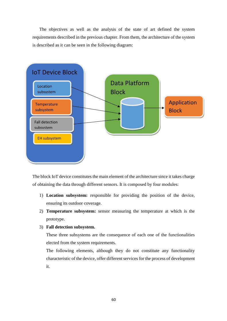
60
The objectives as well as the analysis of the state of art defined the system
requirements described in the previous chapter. From them, the architecture of the system
is described as it can be seen in the following diagram:
The block IoT device constitutes the main element of the architecture since it takes charge
of obtaining the data through different sensors. It is composed by four modules:
1) Location subsystem: responsible for providing the position of the device,
ensuring its outdoor coverage.
2) Temperature subsystem: sensor measuring the temperature at which is the
prototype.
3) Fall detection subsystem.
These three subsystems are the consequence of each one of the functionalities
elected from the system requirements.
The following elements, although they do not constitute any functionality
characteristic of the device, offer different services for the process of development
it.
IoT Device Block
Location
subsystem
Temperature
subsystem
Fall detection
subsystem
EH subsystem
Data Platform
Block
Application
Block

61
4) Energy Harvesting subsystem: system that implements some of the EH
mechanisms previously seen by providing an energy solution for the device.
The following block is formed by a data platform in which the data collected by the
block IoT device will be stored.
Finally the application block will be in charge of recovering the data from the platform
and interpreting them in order to offer a specific service to the device users.
The architecture follows a logic sequence regarding the obtaining, the storage and the
processing of the data of tele-assisstance. Great part of the development of this project, is
centred in the design of the block IoT device, leaving the rest of elements as blocks to
add and to improve in future designs.
Next it will exposed a brief presentation of all the elements present that are included
in the architecture of the prototype:
6.2 )IoT DEVICE BLOCK
The module of the device will provide the different data obtained by the sensors.
Following the defined objectives and in accordance with the elected functionalities that
will be offered by the prototype, there can be distinguished four different subsystems,
considering that each one of them will offer the required service:
6.2.1) Location subsystem
As it has been explained throughout the project, the location of a user is a key
feature to be able to offer assistance in the event of emergency. There have been also
exposed the most important techniques that are used at the moment for the localization of
a device such as satellite technology and the technology based on mobile networks.
The location subsystem will be implemented by means of a module that will be
able to obtain the space coordinates by means of the employment of some of these
techniques.
For the use of the mobile network, it will be needed an element able to be
connected to the frequency bands used by GSM network by means of a SIM card in
order to obtain all the services through the network.
62
If it is sought to locate the element by means of the satellite positioning, hardware
with GPS integrated technology will be used.
For both technologies it will be needed an antenna and own hardware.
6.2.2) Temperature Subsystem
This subsystem should be capable to constantly measure the prototype
temperature and guarantee an alarm system which is activated when abnormal
temperature is detected.
The configuration of each alarm is defined in forthcoming sections where the
subsystem is implemented. In tele-assistance field, it could be interesting to activate
alarms when it is detected temperature that is higher than room temperature, or on the
contrary, when the device receives a temperature value too small.
This subsystem implementation is done by using a temperature sensor.
In current market, there are quite a few sensors providing correct temperature
readings.
The basic operation principle of these sensors is calculating temperature from
generated tension.
These sensors are generally composed of a diode which voltage increases as
temperature does. This increase is detected by the sensor and by amplifying the voltage
properly, an analogue signal is created which is directly proportional to the temperature.
6.2.3) Fall detection subsystem
As in the previous subsystem, a user fall detection is a service to offer very
interesting in the tele-assistance field.
An alarm system is in charge of notifying about a user possible fall detection.
63
Its implementation can be done by using some types of sensors, particularly for the
prototype to develop, there have been analysed two possible elements: barometer and
accelerometer.
- Detection using a barometer: a barometer is an instrument that provides the
atmospheric pressure on a specific point. Following one of the atmospheric laws
on Earth planet, it is a fact that as height increases pressure decreases. Thus,
connecting heights and pressures an algorithm can be designed, that by calculating
pressure difference on successive instants, detects height difference that could be
a device fall. There are some commercial models of barometer designed for
wearable elements and IoT.
- Detection using an Accelerometer: by using this instrument, it can be detected
accelerations in any of the three spatial axes. If an acceleration threshold is defined
as it could indicate a fall, then any movement exceeding the defined threshold can
be detected by using an accelerometer.
6.2.4) Energy Harvesting subsystem
As discussed in previous sections, energy harvesting and its efficient use is one of
the key points to research about wearable technology.
Because of the early stage in which all explained EH technologies are in the
section of the state of the art, it deserves to be mentioned the possibility of introducing a
piezoelectric EH block in later versions of the prototype.
This subsystem should be able to offer a superior autonomy or the possibility of
dispensing with traditional batteries, by collecting energy by the motion of the user. A
future device design should aim to maximize its usage detection.
6.3) Data platform block
The presence of this subsystem is justified as an answer to the next question:
Where is saved the data obtained by an IoT device?
The sensors found in the prototype allow to read different data in real-time, such
as the position of the device or the temperature at which it is found.
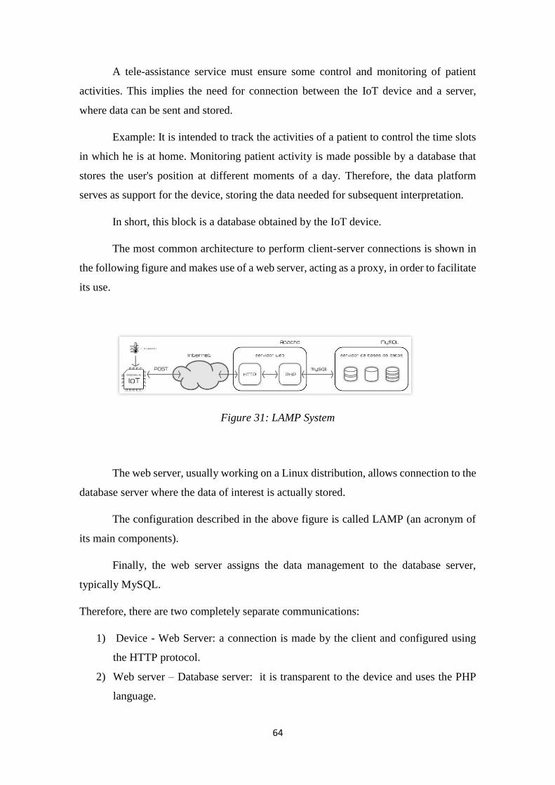
64
A tele-assistance service must ensure some control and monitoring of patient
activities. This implies the need for connection between the IoT device and a server,
where data can be sent and stored.
Example: It is intended to track the activities of a patient to control the time slots
in which he is at home. Monitoring patient activity is made possible by a database that
stores the user's position at different moments of a day. Therefore, the data platform
serves as support for the device, storing the data needed for subsequent interpretation.
In short, this block is a database obtained by the IoT device.
The most common architecture to perform client-server connections is shown in
the following figure and makes use of a web server, acting as a proxy, in order to facilitate
its use.
Figure 31: LAMP System
The web server, usually working on a Linux distribution, allows connection to the
database server where the data of interest is actually stored.
The configuration described in the above figure is called LAMP (an acronym of
its main components).
Finally, the web server assigns the data management to the database server,
typically MySQL.
Therefore, there are two completely separate communications:
1) Device - Web Server: a connection is made by the client and configured using
the HTTP protocol.
2) Web server – Database server: it is transparent to the device and uses the PHP
language.
65
Communication between the device and the web server is performed by the following
two instructions:
1) HTTP Post: The IoT device requests to store data in the database.
2) HTTP GET: The IoT device or another system application requires to retrieve data
from the server.
Without describing technical details of how these actions are performed, since it will
be described deeply in subsequent sections, there will be described the elements in the
data platform and its basic operation.
6.4) Application
This last block of prototype scheme allows monitoring and interpretation of data
stored.
If the data platform answered the question: Where is the data stored? Thus the
application does to the following question: What to do with it?
If a database is available, it is necessary an application to interpret the data and
provide the desired services.
Example:
- The positioning subsystem stores the latitude and longitude of the device every
minute.
- The platform stores the data along a day.
- A user wants to watch, on a map or graphically, the journey performed.
- The application system would be responsible for, obtaining data from the
platform, representing the position of the device on a map.
Without the existence of this block, only data of different types is available, stored on
a server, the implementation of an application ensures monitoring and device control
services.
66
As observed in the section of the state of the art, almost all tracking devices had its
own proprietary application, from which the various services are offered.
The level of complexity of the application depends on the services to offer.
For the example of the location, there are applications that simply use the Google
Maps application to locate a point on a map to applications that perform a complete real-
time monitoring.
In the next section, it will be detailed the block by block prototype implementation of
the project, describing technologies and devices used and justifying the choice of them.
7) IMPLEMENTATION
7.1) Introduction
Throughout this chapter, it will be described the process of development of the tele-
assistance prototype. This process has been conducted by the student, and author of this
project, at the headquarters of Caratek Company.
The implementation of the device starts from choosing a work environment to the
development of a prototype model that meets the defined objectives.
In order to show a clear overview of all development, the structure followed in this
section will describe comprehensively all the tools used and the different tasks carried out
until the final prototype.
- First, it will be described the work environment offered to the student for the
device implementation.
- Secondly, for each subsystem in the device architecture, the elements used will be
detailed, its programming and experimentation.
- Finally, the subsystems will be combined to produce the prototype and following
an explanation of the utilized techniques, setup phases and results.
In addition to this structure, the points of this chapter shall keep a chronological
coherence and will mention at all times different problems or limitations that any of the
elements involved may have caused.
67
In order to make more understandable the entire process, the introduction of the full
source code of the prototype (it is attached as an annex) is obviated, thus including only
the fragments considered as important which facilitate correct understanding of the
functioning of the elements.
7.2) Work environment
It is defined as working environment, the initial set of tools available to the student
which have allowed the development of the prototype.
The elements included are the following:
- Programming language and framework.
- Sensors.
- Breadboard (protoboard).
- Computer.
Programming language and framework
As any other electronic device, a programming language that indicates the
processes to be performed at any time will be required.
Because of the features desired for the prototype, it makes no sense to use complex
and heavy programming languages, generally aimed at large systems and machines.
At present, there are different systems specifically aimed at small, wearables
devices belonging to the IoT.
Among all of them, it was decided to implement a system based on Arduino code
platform.
Arduino
This platform is intended for creating flexible and easy to use prototypes, following there
are some of the most important reasons for its choice.
1) Easy programming: The platform uses a high-level language based on C. It
supports all C and C++ functions. In addition, it has an integrated development
68
environment (IDE) which is very intuitive and simple to any user familiar with
programming languages.
2) The existence of a large amount of documentation and materials that greatly
facilitate learning.
3) Open Source platform, with all the advantages this brings.
4) Use of libraries through which a large number of external components can be
configured and programmed. As noted in the following points, for most
peripherals used in the prototype, there were libraries for configuration and
smooth operation.
5) Versatility: Arduino is different from other development platforms in terms of the
variety of plates it offers on the market. Each offers individual and different
features. Next, the plates used in the development process of the device will be
mentioned.
6) Peripherals: Perhaps the most important benefit of all. An Arduino-based system
offers a wide range of Shields and peripherals that can be incorporated simply by
increasing the range of applications and services. For this project, in each
subsystem, different peripherals have been used.
In the annex, all the detailed documentation will be attached since they allows a first
contact with the Arduino platform and the steps to gain sufficient assurance for the
preparation of a project.
The goal of this point is simply to inform about the programming language and
platform used and the reasons for that choice.
The key element of a platform based on the Arduino system is constituted by the plate
containing the microprocessor.
The microprocessor is responsible for executing programs and indicating the
instructions to be followed by the different elements of the system.

69
As stated previously, there are a variety of plates available in the market. Each offers
different benefits.
Below, those used throughout the implementation process are listed, by using a
comparison chart which allows to observe each main features.
In the following sections, the plate used for experimentation will be detailed, and caused
problems, if they ever happened.
Name Processor Input
Voltage
CPU
Speed
Analog
In/Out
Digital
IO/PWM
EEPROM
[kB]
SRAM
[kB]
Flash
[kB]
USB UART
101 Intel Curie 3.3V/7-12V 32MHz 6/0 14/4 - 24 196 Regular -
Micro ATmega32U4 5V/7-12 16MHz 12/0 20/7 1 2.5 32 Micro 1
Uno ATmega328P 5V/7-12V 16MHz 6/0 14/6 1 2 32 Regular 1
Nano ATmega328P 5V/7-9V 16MHz 8/0 14/6 1 2 32 Mini 1
Sensors
Recalling the architecture of the prototype, it has several subsystems that will
make up the final model. The implementation of some of these subsystems is carried out
by sensors and peripherals external to the Arduino board. Those are described in the
following topics of the section and they are also part of the work environment.
Breadboard and Computer
Once one has a development platform, a microprocessor, and the necessary
peripherals, the connection between them is necessary.
The peripherals are connected to the Arduino board using a breadboard, which
offers the ability to assemble and disassemble circuits easily.
70
The computer will load the program to run on the processor, connecting to it via
USB. Besides, thanks to the Arduino IDE loaded program results can be displayed
directly on the computer screen thanks to the serial output.
All these elements are in the working environment in which the student has developed
the prototype through the steps detailed in the following points.
7.3) Subsystems implementation:
As detailed in the architecture of the system, the prototype has three different blocks:
1) IoT Block, composed by the following subsystems:
-Location subsystem.
-Temperature Subsystem
-Fall detection subsystem.
-EH subsystem.
2) Data platform.
3) Application.
The development of the device is determined by the implementation of each of these
blocks and the final combination, forming the complete model.
In this section, the implementation process of each subsystem will be detailed,
following the algorithm "divide and conquer".
By implementing each block separately, to later combining them, a much simpler
process is obtained which greatly facilitates the tasks of checking, error correction and
testing the system.
Thus, the basic analysis structure for each block is as follows:
1) Presentation of the elements involved and the chosen technologies.
2) Software programming of different programs.
3) Experimentation and obtained results.
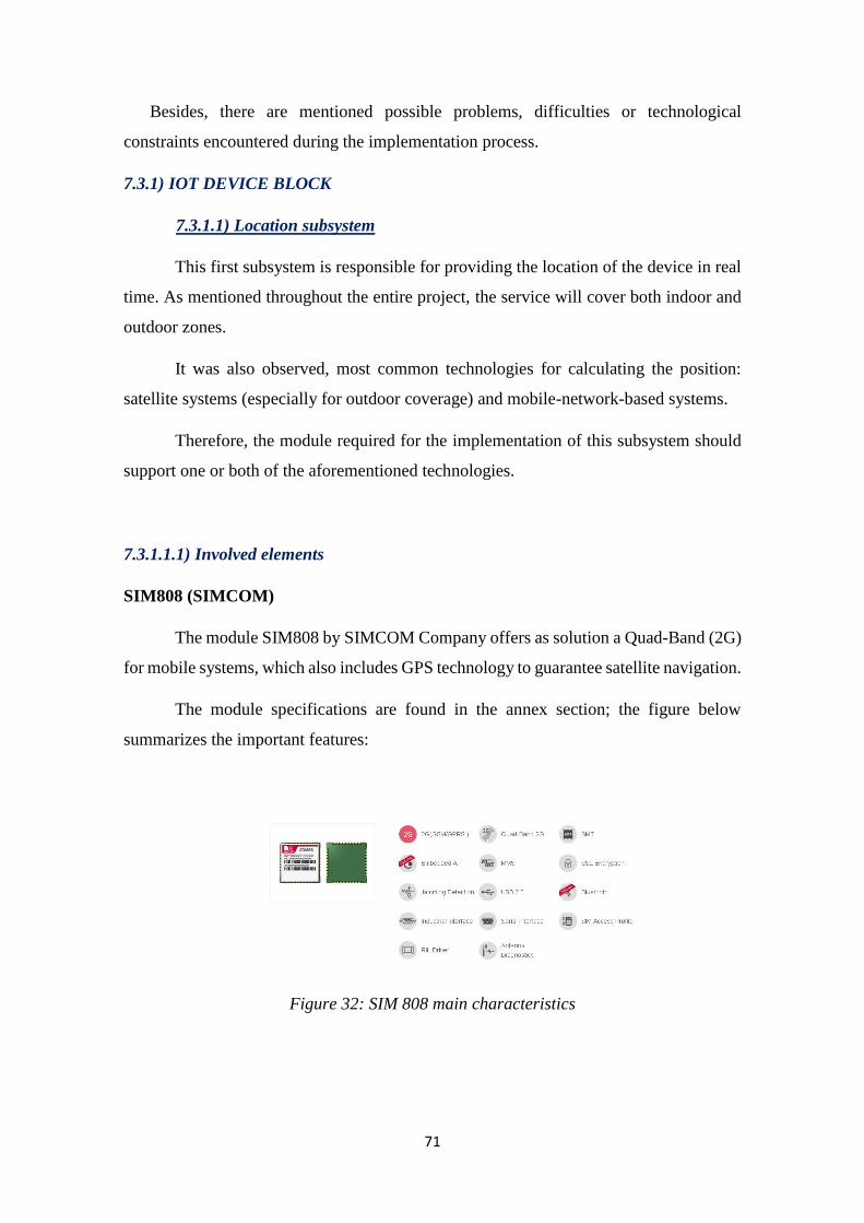
71
Besides, there are mentioned possible problems, difficulties or technological
constraints encountered during the implementation process.
7.3.1) IOT DEVICE BLOCK
7.3.1.1) Location subsystem
This first subsystem is responsible for providing the location of the device in real
time. As mentioned throughout the entire project, the service will cover both indoor and
outdoor zones.
It was also observed, most common technologies for calculating the position:
satellite systems (especially for outdoor coverage) and mobile-network-based systems.
Therefore, the module required for the implementation of this subsystem should
support one or both of the aforementioned technologies.
7.3.1.1.1) Involved elements
SIM808 (SIMCOM)
The module SIM808 by SIMCOM Company offers as solution a Quad-Band (2G)
for mobile systems, which also includes GPS technology to guarantee satellite navigation.
The module specifications are found in the annex section; the figure below
summarizes the important features:
Figure 32: SIM 808 main characteristics
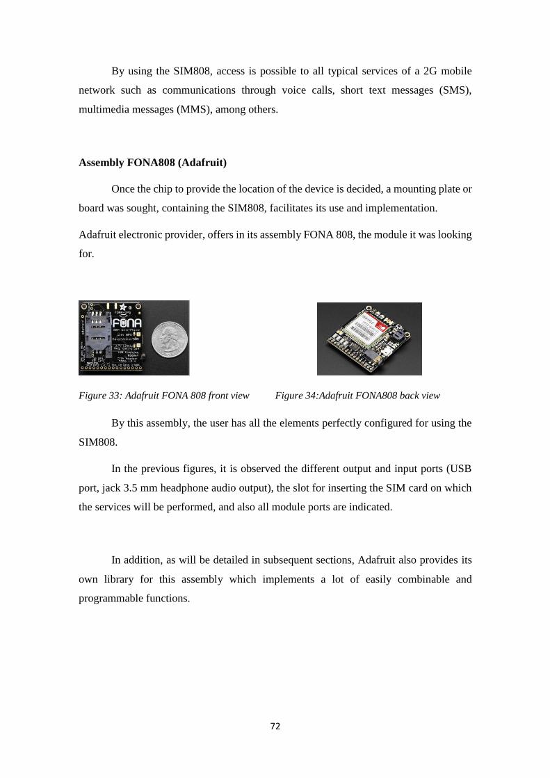
72
By using the SIM808, access is possible to all typical services of a 2G mobile
network such as communications through voice calls, short text messages (SMS),
multimedia messages (MMS), among others.
Assembly FONA808 (Adafruit)
Once the chip to provide the location of the device is decided, a mounting plate or
board was sought, containing the SIM808, facilitates its use and implementation.
Adafruit electronic provider, offers in its assembly FONA 808, the module it was looking
for.
Figure 33: Adafruit FONA 808 front view Figure 34:Adafruit FONA808 back view
By this assembly, the user has all the elements perfectly configured for using the
SIM808.
In the previous figures, it is observed the different output and input ports (USB
port, jack 3.5 mm headphone audio output), the slot for inserting the SIM card on which
the services will be performed, and also all module ports are indicated.
In addition, as will be detailed in subsequent sections, Adafruit also provides its
own library for this assembly which implements a lot of easily combinable and
programmable functions.
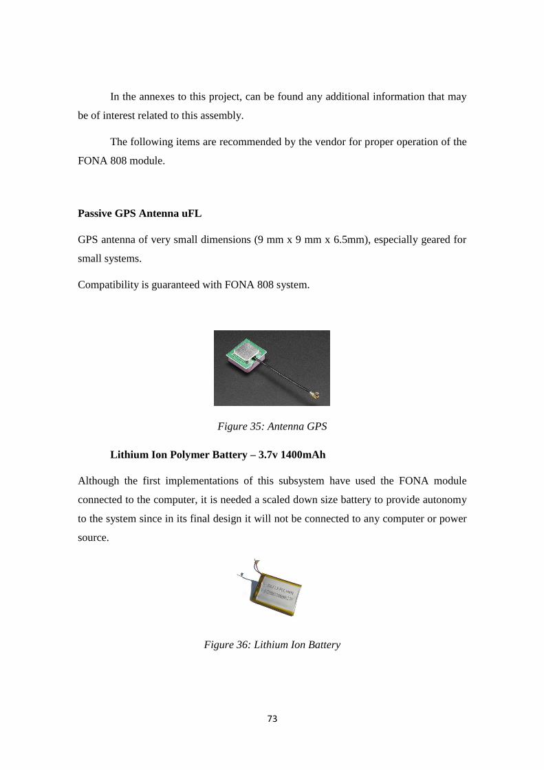
73
In the annexes to this project, can be found any additional information that may
be of interest related to this assembly.
The following items are recommended by the vendor for proper operation of the
FONA 808 module.
Passive GPS Antenna uFL
GPS antenna of very small dimensions (9 mm x 9 mm x 6.5mm), especially geared for
small systems.
Compatibility is guaranteed with FONA 808 system.
Figure 35: Antenna GPS
Lithium Ion Polymer Battery – 3.7v 1400mAh
Although the first implementations of this subsystem have used the FONA module
connected to the computer, it is needed a scaled down size battery to provide autonomy
to the system since in its final design it will not be connected to any computer or power
source.
Figure 36: Lithium Ion Battery
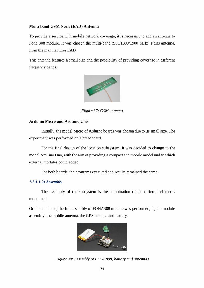
74
Multi-band GSM Neris (EAD) Antenna
To provide a service with mobile network coverage, it is necessary to add an antenna to
Fona 808 module. It was chosen the multi-band (900/1800/1900 MHz) Neris antenna,
from the manufacturer EAD.
This antenna features a small size and the possibility of providing coverage in different
frequency bands.
Figure 37: GSM antenna
Arduino Micro and Arduino Uno
Initially, the model Micro of Arduino boards was chosen due to its small size. The
experiment was performed on a breadboard.
For the final design of the location subsystem, it was decided to change to the
model Arduino Uno, with the aim of providing a compact and mobile model and to which
external modules could added.
For both boards, the programs executed and results remained the same.
7.3.1.1.2) Assembly
The assembly of the subsystem is the combination of the different elements
mentioned.
On the one hand, the full assembly of FONA808 module was performed, ie, the module
assembly, the mobile antenna, the GPS antenna and battery:
Figure 38: Assembly of FONA808, battery and antennas
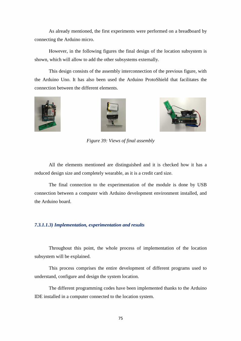
75
As already mentioned, the first experiments were performed on a breadboard by
connecting the Arduino micro.
However, in the following figures the final design of the location subsystem is
shown, which will allow to add the other subsystems externally.
This design consists of the assembly interconnection of the previous figure, with
the Arduino Uno. It has also been used the Arduino ProtoShield that facilitates the
connection between the different elements.
Figure 39: Views of final assembly
All the elements mentioned are distinguished and it is checked how it has a
reduced design size and completely wearable, as it is a credit card size.
The final connection to the experimentation of the module is done by USB
connection between a computer with Arduino development environment installed, and
the Arduino board.
7.3.1.1.3) Implementation, experimentation and results
Throughout this point, the whole process of implementation of the location
subsystem will be explained.
This process comprises the entire development of different programs used to
understand, configure and design the system location.
The different programming codes have been implemented thanks to the Arduino
IDE installed in a computer connected to the location system.
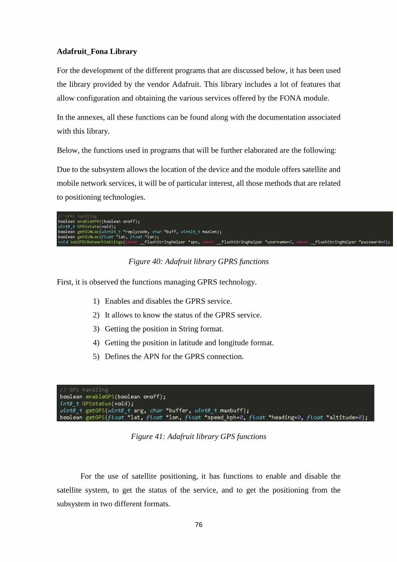
76
Adafruit_Fona Library
For the development of the different programs that are discussed below, it has been used
the library provided by the vendor Adafruit. This library includes a lot of features that
allow configuration and obtaining the various services offered by the FONA module.
In the annexes, all these functions can be found along with the documentation associated
with this library.
Below, the functions used in programs that will be further elaborated are the following:
Due to the subsystem allows the location of the device and the module offers satellite and
mobile network services, it will be of particular interest, all those methods that are related
to positioning technologies.
Figure 40: Adafruit library GPRS functions
First, it is observed the functions managing GPRS technology.
1) Enables and disables the GPRS service.
2) It allows to know the status of the GPRS service.
3) Getting the position in String format.
4) Getting the position in latitude and longitude format.
5) Defines the APN for the GPRS connection.
Figure 41: Adafruit library GPS functions
For the use of satellite positioning, it has functions to enable and disable the
satellite system, to get the status of the service, and to get the positioning from the
subsystem in two different formats.
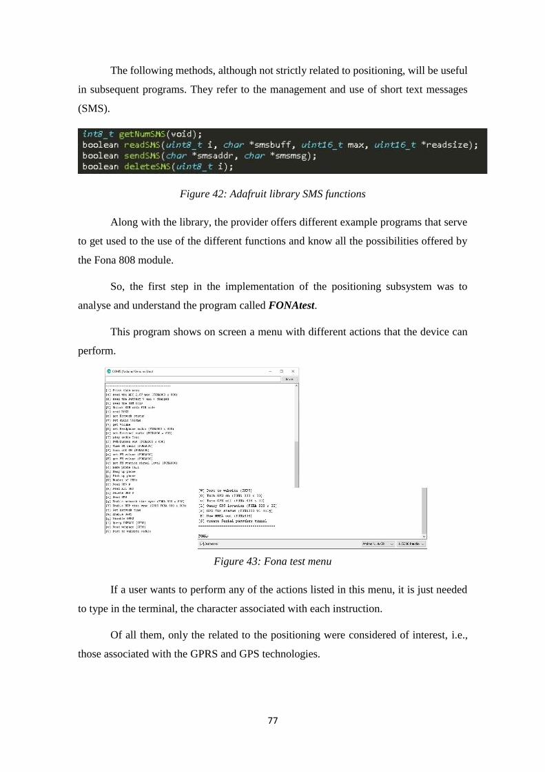
77
The following methods, although not strictly related to positioning, will be useful
in subsequent programs. They refer to the management and use of short text messages
(SMS).
Figure 42: Adafruit library SMS functions
Along with the library, the provider offers different example programs that serve
to get used to the use of the different functions and know all the possibilities offered by
the Fona 808 module.
So, the first step in the implementation of the positioning subsystem was to
analyse and understand the program called FONAtest.
This program shows on screen a menu with different actions that the device can
perform.
Figure 43: Fona test menu
If a user wants to perform any of the actions listed in this menu, it is just needed
to type in the terminal, the character associated with each instruction.
Of all them, only the related to the positioning were considered of interest, i.e.,
those associated with the GPRS and GPS technologies.
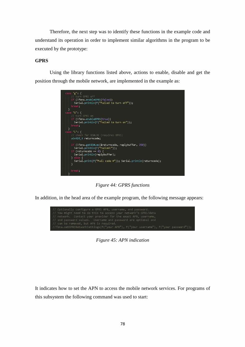
78
Therefore, the next step was to identify these functions in the example code and
understand its operation in order to implement similar algorithms in the program to be
executed by the prototype:
GPRS
Using the library functions listed above, actions to enable, disable and get the
position through the mobile network, are implemented in the example as:
Figure 44: GPRS functions
In addition, in the head area of the example program, the following message appears:
Figure 45: APN indication
It indicates how to set the APN to access the mobile network services. For programs of
this subsystem the following command was used to start:
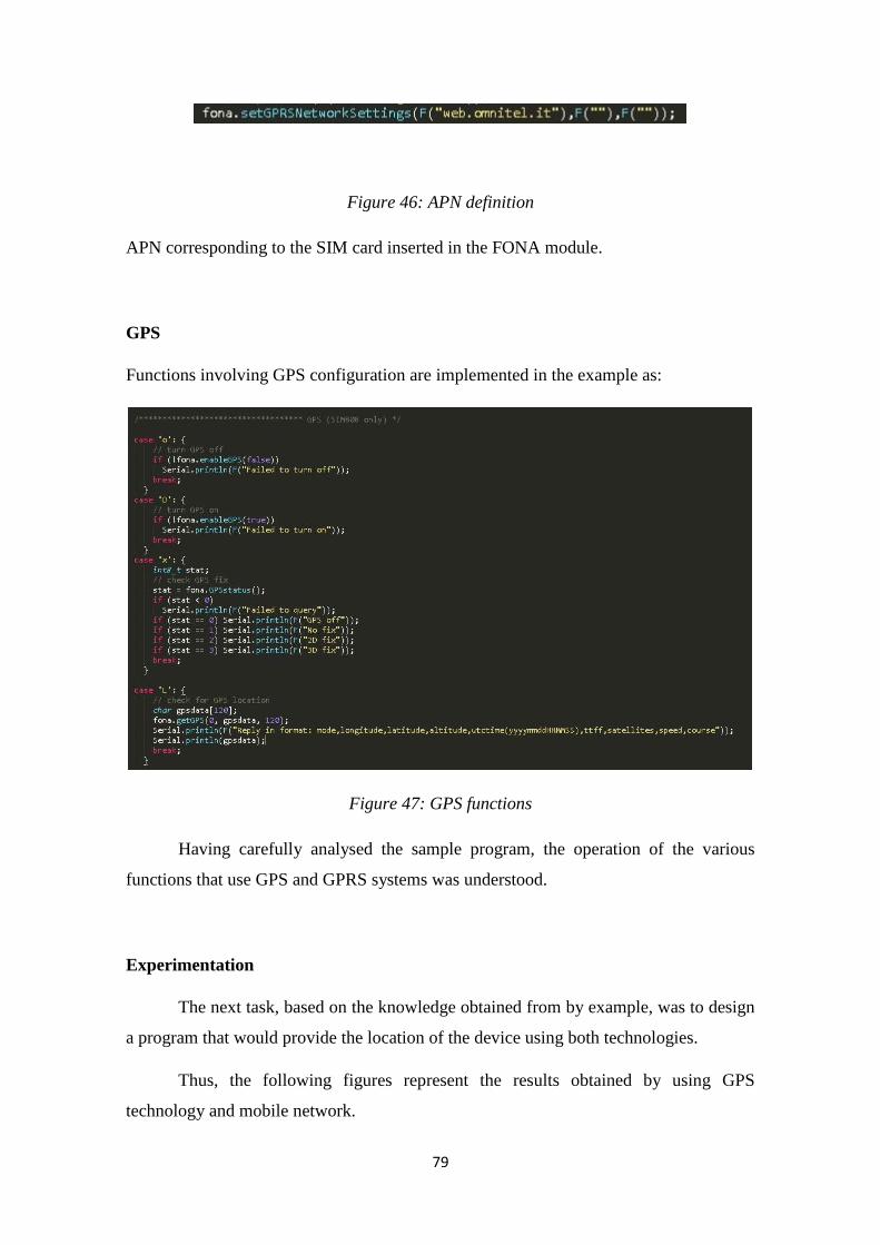
79
Figure 46: APN definition
APN corresponding to the SIM card inserted in the FONA module.
GPS
Functions involving GPS configuration are implemented in the example as:
Figure 47: GPS functions
Having carefully analysed the sample program, the operation of the various
functions that use GPS and GPRS systems was understood.
Experimentation
The next task, based on the knowledge obtained from by example, was to design
a program that would provide the location of the device using both technologies.
Thus, the following figures represent the results obtained by using GPS
technology and mobile network.
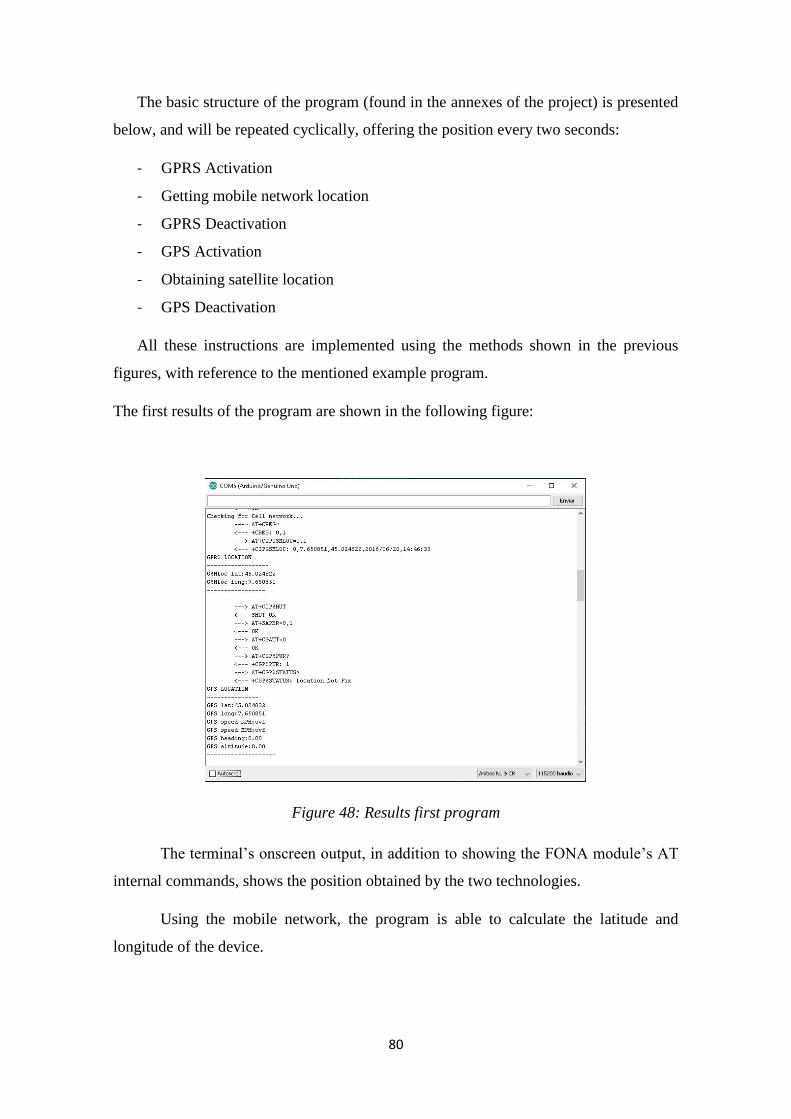
80
The basic structure of the program (found in the annexes of the project) is presented
below, and will be repeated cyclically, offering the position every two seconds:
- GPRS Activation
- Getting mobile network location
- GPRS Deactivation
- GPS Activation
- Obtaining satellite location
- GPS Deactivation
All these instructions are implemented using the methods shown in the previous
figures, with reference to the mentioned example program.
The first results of the program are shown in the following figure:
Figure 48: Results first program
The terminal’s onscreen output, in addition to showing the FONA module’s AT
internal commands, shows the position obtained by the two technologies.
Using the mobile network, the program is able to calculate the latitude and
longitude of the device.
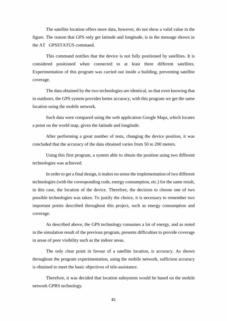
81
The satellite location offers more data, however, do not show a valid value in the
figure. The reason that GPS only get latitude and longitude, is in the message shown in
the AT GPSSTATUS command.
This command notifies that the device is not fully positioned by satellites. It is
considered positioned when connected to at least three different satellites.
Experimentation of this program was carried out inside a building, preventing satellite
coverage.
The data obtained by the two technologies are identical, so that even knowing that
in outdoors, the GPS system provides better accuracy, with this program we get the same
location using the mobile network.
Such data were compared using the web application Google Maps, which locates
a point on the world map, given the latitude and longitude.
After performing a great number of tests, changing the device position, it was
concluded that the accuracy of the data obtained varies from 50 to 200 meters.
Using this first program, a system able to obtain the position using two different
technologies was achieved.
In order to get a final design, it makes no sense the implementation of two different
technologies (with the corresponding code, energy consumption, etc.) for the same result,
in this case, the location of the device. Therefore, the decision to choose one of two
possible technologies was taken. To justify the choice, it is necessary to remember two
important points described throughout this project, such as energy consumption and
coverage.
As described above, the GPS technology consumes a lot of energy, and as noted
in the simulation result of the previous program, presents difficulties to provide coverage
in areas of poor visibility such as the indoor areas.
The only clear point in favour of a satellite location, is accuracy. As shown
throughout the program experimentation, using the mobile network, sufficient accuracy
is obtained to meet the basic objectives of tele-assistance.
Therefore, it was decided that location subsystem would be based on the mobile
network GPRS technology.
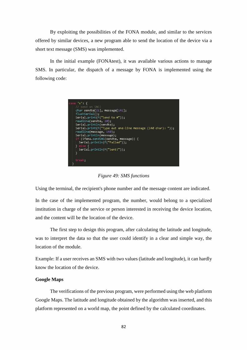
82
By exploiting the possibilities of the FONA module, and similar to the services
offered by similar devices, a new program able to send the location of the device via a
short text message (SMS) was implemented.
In the initial example (FONAtest), it was available various actions to manage
SMS. In particular, the dispatch of a message by FONA is implemented using the
following code:
Figure 49: SMS functions
Using the terminal, the recipient's phone number and the message content are indicated.
In the case of the implemented program, the number, would belong to a specialized
institution in charge of the service or person interested in receiving the device location,
and the content will be the location of the device.
The first step to design this program, after calculating the latitude and longitude,
was to interpret the data so that the user could identify in a clear and simple way, the
location of the module.
Example: If a user receives an SMS with two values (latitude and longitude), it can hardly
know the location of the device.
Google Maps
The verifications of the previous program, were performed using the web platform
Google Maps. The latitude and longitude obtained by the algorithm was inserted, and this
platform represented on a world map, the point defined by the calculated coordinates.

83
In addition to the web platform, Google Maps has its own application designed
for portable devices and Smartphones, therefore, if the program to be designed was able
to create an SMS whose contents were directly interpretable by Google Maps, the user
could view on a map quickly and clearly.
Therefore, the program will send an SMS with a valid link of the Google Maps
application to the interested person’s phone number.
Google maps allows visualization, been possible to insert the coordinates to represent or
directly the address of interest.
Figure 50: Google Maps
The goal of the module is to locate the device, so the address will be unknown at
all time. Thus, a URL accepted by Google Maps platform was built so that from a latitude
and longitude, coordinates could represent on the map.
The URL should always follow the following structure supported by the platform:
Being the latitude and longitude, the data that has been obtained by GPRS
technology in the previous program.
Finally, the structure of this algorithm is:
- Enable GPRS.
- Get the position by mobile network (latitude, longitude).
- Build Google Maps link.
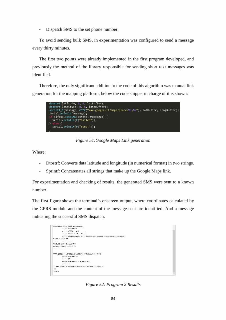
84
- Dispatch SMS to the set phone number.
To avoid sending bulk SMS, in experimentation was configured to send a message
every thirty minutes.
The first two points were already implemented in the first program developed, and
previously the method of the library responsible for sending short text messages was
identified.
Therefore, the only significant addition to the code of this algorithm was manual link
generation for the mapping platform, below the code snippet in charge of it is shown:
Figure 51:Google Maps Link generation
Where:
- Dtostrf: Converts data latitude and longitude (in numerical format) in two strings.
- Sprintf: Concatenates all strings that make up the Google Maps link.
For experimentation and checking of results, the generated SMS were sent to a known
number.
The first figure shows the terminal’s onscreen output, where coordinates calculated by
the GPRS module and the content of the message sent are identified. And a message
indicating the successful SMS dispatch.
Figure 52: Program 2 Results
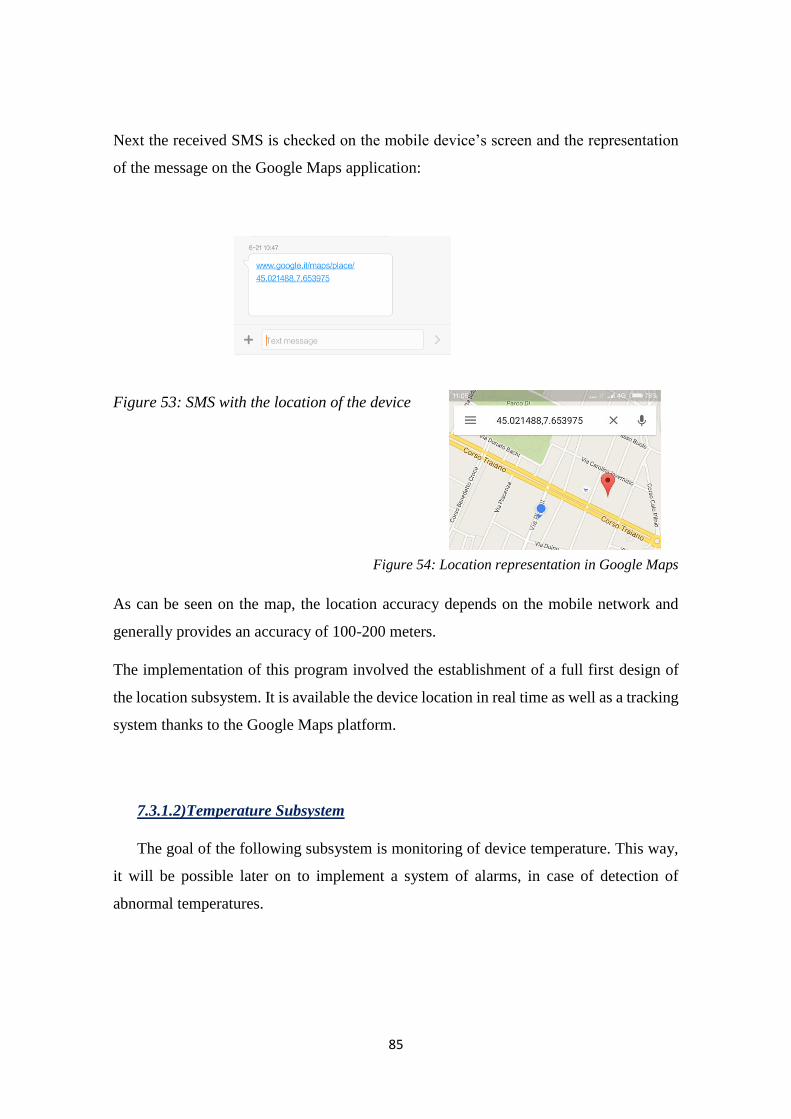
85
Next the received SMS is checked on the mobile device’s screen and the representation
of the message on the Google Maps application:
Figure 53: SMS with the location of the device
Figure 54: Location representation in Google Maps
As can be seen on the map, the location accuracy depends on the mobile network and
generally provides an accuracy of 100-200 meters.
The implementation of this program involved the establishment of a full first design of
the location subsystem. It is available the device location in real time as well as a tracking
system thanks to the Google Maps platform.
7.3.1.2)Temperature Subsystem
The goal of the following subsystem is monitoring of device temperature. This way,
it will be possible later on to implement a system of alarms, in case of detection of
abnormal temperatures.
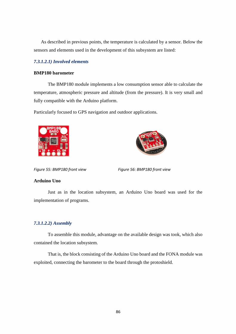
86
As described in previous points, the temperature is calculated by a sensor. Below the
sensors and elements used in the development of this subsystem are listed:
7.3.1.2.1) Involved elements
BMP180 barometer
The BMP180 module implements a low consumption sensor able to calculate the
temperature, atmospheric pressure and altitude (from the pressure). It is very small and
fully compatible with the Arduino platform.
Particularly focused to GPS navigation and outdoor applications.
Figure 55: BMP180 front view Figure 56: BMP180 front view
Arduino Uno
Just as in the location subsystem, an Arduino Uno board was used for the
implementation of programs.
7.3.1.2.2) Assembly
To assemble this module, advantage on the available design was took, which also
contained the location subsystem.
That is, the block consisting of the Arduino Uno board and the FONA module was
exploited, connecting the barometer to the board through the protoshield.

87
Figure 57: Assembly of the BMP180
In spite of being two different subsystems, the final design should be able to
combine them all in a compact and efficient way in terms of energy, so this assembly can
provide solutions that combine the location and temperature subsystems.
7.3.1.2.3) Implementation, experimentation and results
The implementation of this subsystem was performed by the program that will be
described below.
Just as for the module to get the location, a library specially developed for the
BMP180 barometer was used, in a programming environment.
SFE_BMP180 Library
In the library, all the methods that the barometer is able to perform are declared and
defined. To get the temperature from the sensor, the following ones were identified:
Figure 58: SFE_BMP180 Library Temperature
In addition to calculating the temperature, it is considered handy to use the functions
related to pressure and altitude in order to explore the capabilities of the BMP180
Barometer.
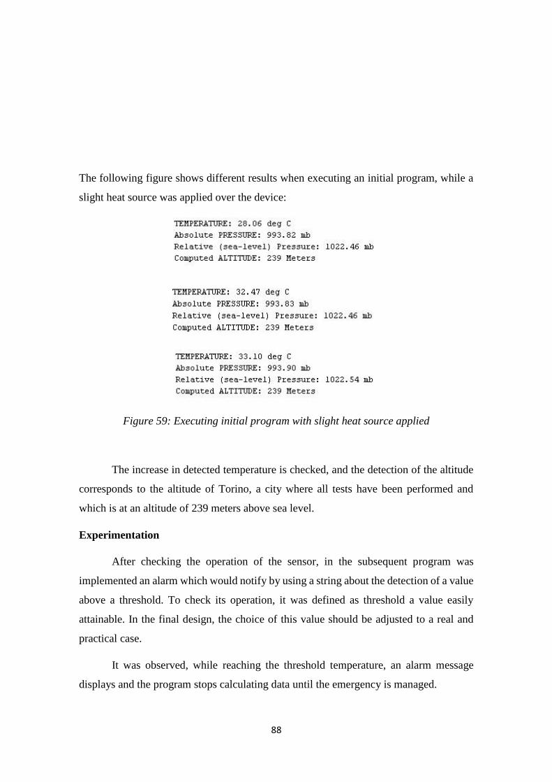
88
The following figure shows different results when executing an initial program, while a
slight heat source was applied over the device:
Figure 59: Executing initial program with slight heat source applied
The increase in detected temperature is checked, and the detection of the altitude
corresponds to the altitude of Torino, a city where all tests have been performed and
which is at an altitude of 239 meters above sea level.
Experimentation
After checking the operation of the sensor, in the subsequent program was
implemented an alarm which would notify by using a string about the detection of a value
above a threshold. To check its operation, it was defined as threshold a value easily
attainable. In the final design, the choice of this value should be adjusted to a real and
practical case.
It was observed, while reaching the threshold temperature, an alarm message
displays and the program stops calculating data until the emergency is managed.

89
At this point of development of the first subsystems, a set of modules able to
calculate the location and temperature of the device were available.
In order to get closer to an autonomous and practical system (without being
connected to a computer), then it was proposed the combination of the first two
subsystems to manage the temperature alarms system.
The program described below, uses the possibilities of the FONA module to send
SMS to implement an algorithm which:
- Calculates in real time the temperature of the device.
- If a temperature higher than the threshold value is detected, activate the GPRS
service.
- Gets the device location.
- Sends SMS notifying a temperature alarm and indicating the location of the
device.
By this structure, the energy consumption of the continuous usage of the mobile
network is avoided, only activating the location service in case of alarm.
The SMS would show a temperature alarm message, and a link for viewing the
location on the map on the Google Maps platform, as explained before.
The receiver of the message, once the alarm has been identified, might contact the
user wearing the device to check the situation in he is in, or request different services such
as specialized assistance or a more comprehensive monitoring to see the behaviour of the
device.
Figure 60: Temperature alarm results sms & google maps
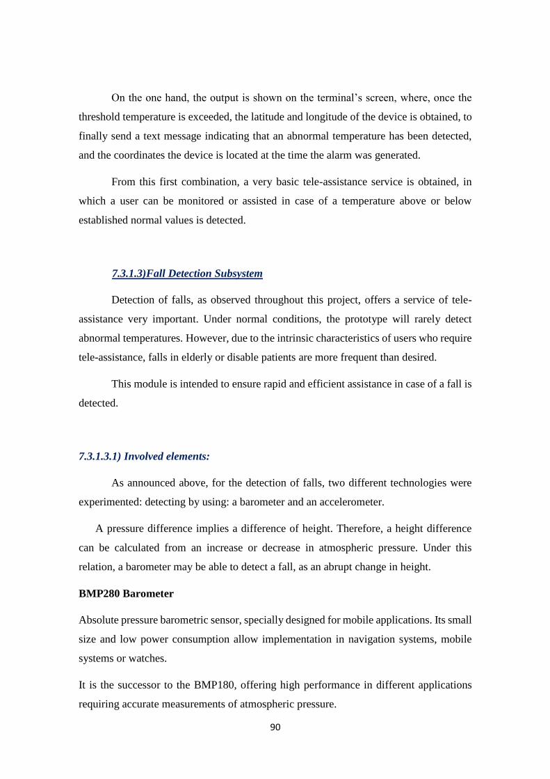
90
On the one hand, the output is shown on the terminal’s screen, where, once the
threshold temperature is exceeded, the latitude and longitude of the device is obtained, to
finally send a text message indicating that an abnormal temperature has been detected,
and the coordinates the device is located at the time the alarm was generated.
From this first combination, a very basic tele-assistance service is obtained, in
which a user can be monitored or assisted in case of a temperature above or below
established normal values is detected.
7.3.1.3)Fall Detection Subsystem
Detection of falls, as observed throughout this project, offers a service of tele-
assistance very important. Under normal conditions, the prototype will rarely detect
abnormal temperatures. However, due to the intrinsic characteristics of users who require
tele-assistance, falls in elderly or disable patients are more frequent than desired.
This module is intended to ensure rapid and efficient assistance in case of a fall is
detected.
7.3.1.3.1) Involved elements:
As announced above, for the detection of falls, two different technologies were
experimented: detecting by using: a barometer and an accelerometer.
A pressure difference implies a difference of height. Therefore, a height difference
can be calculated from an increase or decrease in atmospheric pressure. Under this
relation, a barometer may be able to detect a fall, as an abrupt change in height.
BMP280 Barometer
Absolute pressure barometric sensor, specially designed for mobile applications. Its small
size and low power consumption allow implementation in navigation systems, mobile
systems or watches.
It is the successor to the BMP180, offering high performance in different applications
requiring accurate measurements of atmospheric pressure.
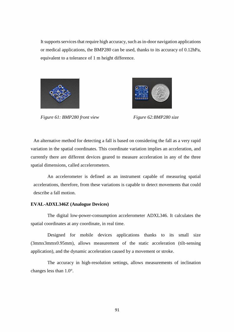
91
It supports services that require high accuracy, such as in-door navigation applications
or medical applications, the BMP280 can be used, thanks to its accuracy of 0.12hPa,
equivalent to a tolerance of 1 m height difference.
Figure 61: BMP280 front view Figure 62:BMP280 size
An alternative method for detecting a fall is based on considering the fall as a very rapid
variation in the spatial coordinates. This coordinate variation implies an acceleration, and
currently there are different devices geared to measure acceleration in any of the three
spatial dimensions, called accelerometers.
An accelerometer is defined as an instrument capable of measuring spatial
accelerations, therefore, from these variations is capable to detect movements that could
describe a fall motion.
EVAL-ADXL346Z (Analogue Devices)
The digital low-power-consumption accelerometer ADXL346. It calculates the
spatial coordinates at any coordinate, in real time.
Designed for mobile devices applications thanks to its small size
(3mmx3mmx0.95mm), allows measurement of the static acceleration (tilt-sensing
application), and the dynamic acceleration caused by a movement or stroke.
The accuracy in high-resolution settings, allows measurements of inclination
changes less than 1.0°.
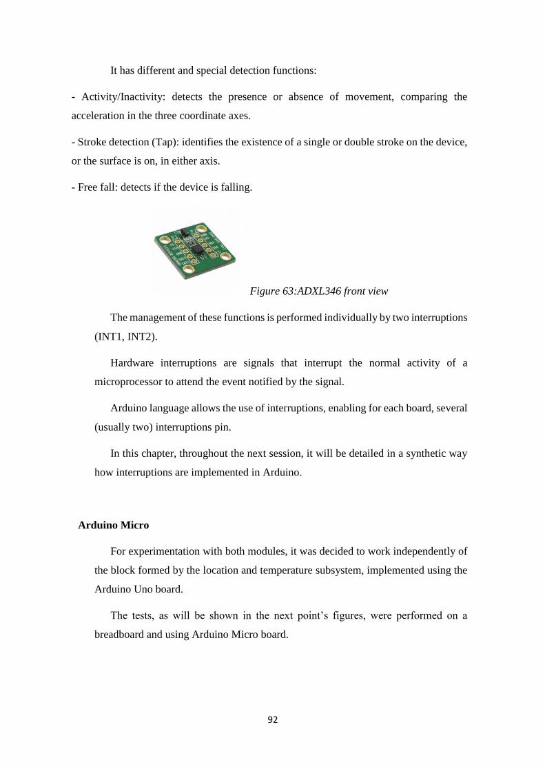
92
It has different and special detection functions:
- Activity/Inactivity: detects the presence or absence of movement, comparing the
acceleration in the three coordinate axes.
- Stroke detection (Tap): identifies the existence of a single or double stroke on the device,
or the surface is on, in either axis.
- Free fall: detects if the device is falling.
Figure 63:ADXL346 front view
The management of these functions is performed individually by two interruptions
(INT1, INT2).
Hardware interruptions are signals that interrupt the normal activity of a
microprocessor to attend the event notified by the signal.
Arduino language allows the use of interruptions, enabling for each board, several
(usually two) interruptions pin.
In this chapter, throughout the next session, it will be detailed in a synthetic way
how interruptions are implemented in Arduino.
Arduino Micro
For experimentation with both modules, it was decided to work independently of
the block formed by the location and temperature subsystem, implemented using the
Arduino Uno board.
The tests, as will be shown in the next point’s figures, were performed on a
breadboard and using Arduino Micro board.
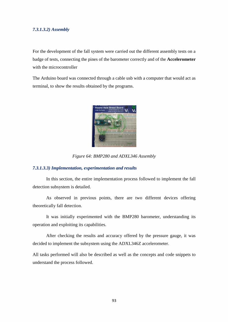
93
7.3.1.3.2) Assembly
For the development of the fall system were carried out the different assembly tests on a
badge of tests, connecting the pines of the barometer correctly and of the Accelerometer
with the microcontroller
The Arduino board was connected through a cable usb with a computer that would act as
terminal, to show the results obtained by the programs.
Figure 64: BMP280 and ADXL346 Assembly
7.3.1.3.3) Implementation, experimentation and results
In this section, the entire implementation process followed to implement the fall
detection subsystem is detailed.
As observed in previous points, there are two different devices offering
theoretically fall detection.
It was initially experimented with the BMP280 barometer, understanding its
operation and exploiting its capabilities.
After checking the results and accuracy offered by the pressure gauge, it was
decided to implement the subsystem using the ADXL346Z accelerometer.
All tasks performed will also be described as well as the concepts and code snippets to
understand the process followed.

94
BMP280 Barometer
The barometer can calculate height differences through the measures of
atmospheric pressure. A first design was done under this principle.
Similarly to the BMP180, the device offers the temperature, pressure and height,
using just the different methods available in his library.
After a first program which calculated all this values, in the same way that was
showed in the first example of the temperature subsystem, the next algorithm was
developed:
- Measure the atmospheric pressure each second.
- From the second iteration, the difference between the pressure in the current
second and the pressure measured in the past second is calculated.
- This pressure difference is converted into height difference, considering the
equivalence showed in the datasheet of the device (an increment of 0.12hPa, is
equivalent to a difference of one meter of height.
In order to establish a notification system in case of falling, it was decided to write an
alert message through the screen terminal when the device had calculated a height
difference bigger than a defined threshold value.
A fall is a loss of height therefore an increase in the pressure. For this fact the
algorithm differentiates two cases:
- UP: When the current value of pressure was higher than the last value measured.
(Which means that there was a pressure increase).
- DOWN: When the pressure has decrease with respect the previous measure.
The algorithm only showed the alarm message in the case that the threshold value was
overcome and the pressure was increased (height decreased).
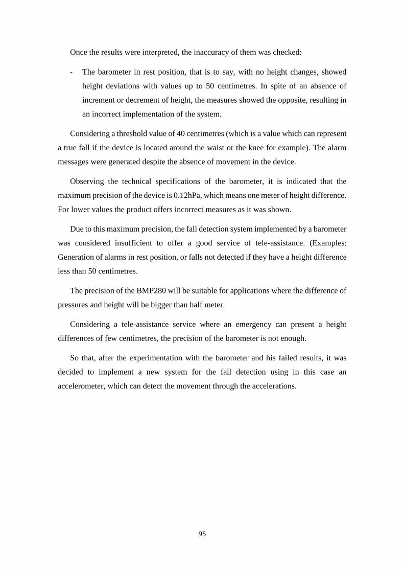
95
Once the results were interpreted, the inaccuracy of them was checked:
- The barometer in rest position, that is to say, with no height changes, showed
height deviations with values up to 50 centimetres. In spite of an absence of
increment or decrement of height, the measures showed the opposite, resulting in
an incorrect implementation of the system.
Considering a threshold value of 40 centimetres (which is a value which can represent
a true fall if the device is located around the waist or the knee for example). The alarm
messages were generated despite the absence of movement in the device.
Observing the technical specifications of the barometer, it is indicated that the
maximum precision of the device is 0.12hPa, which means one meter of height difference.
For lower values the product offers incorrect measures as it was shown.
Due to this maximum precision, the fall detection system implemented by a barometer
was considered insufficient to offer a good service of tele-assistance. (Examples:
Generation of alarms in rest position, or falls not detected if they have a height difference
less than 50 centimetres.
The precision of the BMP280 will be suitable for applications where the difference of
pressures and height will be bigger than half meter.
Considering a tele-assistance service where an emergency can present a height
differences of few centimetres, the precision of the barometer is not enough.
So that, after the experimentation with the barometer and his failed results, it was
decided to implement a new system for the fall detection using in this case an
accelerometer, which can detect the movement through the accelerations.
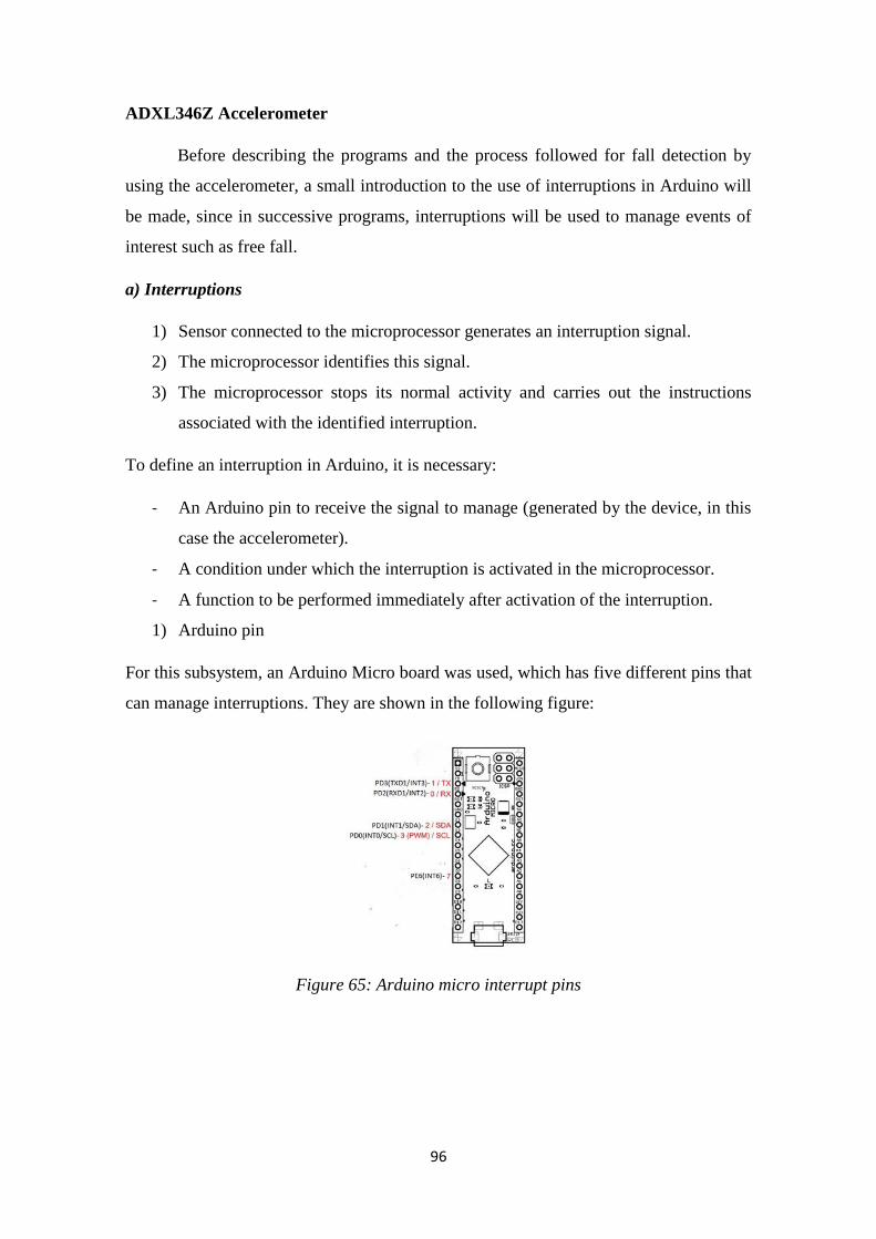
96
ADXL346Z Accelerometer
Before describing the programs and the process followed for fall detection by
using the accelerometer, a small introduction to the use of interruptions in Arduino will
be made, since in successive programs, interruptions will be used to manage events of
interest such as free fall.
a) Interruptions
1) Sensor connected to the microprocessor generates an interruption signal.
2) The microprocessor identifies this signal.
3) The microprocessor stops its normal activity and carries out the instructions
associated with the identified interruption.
To define an interruption in Arduino, it is necessary:
- An Arduino pin to receive the signal to manage (generated by the device, in this
case the accelerometer).
- A condition under which the interruption is activated in the microprocessor.
- A function to be performed immediately after activation of the interruption.
1) Arduino pin
For this subsystem, an Arduino Micro board was used, which has five different pins that
can manage interruptions. They are shown in the following figure:
Figure 65: Arduino micro interrupt pins
97
There are five different pins that can be used for use interruptions, simply connect any
of them with the pin of the device responsible for generating the signal.
2) Interruption condition:
An Arduino Micro, allows the following conditions, which activate the interruption of the
microprocessor.
- Low: The interruption is triggered when the pin generating the signal is in low state.
- Change: It is triggered when the pin undergoes a change of state (High to Low or vice
versa).
- Rising: When the device pin switches from low state to high state.
- Falling: opposite to the previous case.
3) Function to execute:
The set of instructions to be executed after identifying an interruption will depend on the
interruption and the goal of the program.
In order to facilitate the understanding, the following figure shows an example program
that generates a message notifying the existence of an interruption, when the pin detects
a change of state.
The implementation of this program was fundamental for the subsequent use of
interruptions.
Figure 66: Interruption Test
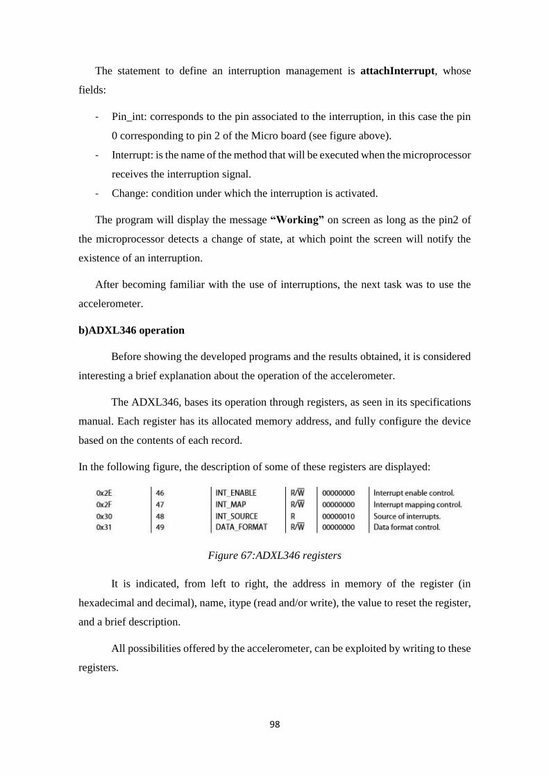
98
The statement to define an interruption management is attachInterrupt, whose
fields:
- Pin_int: corresponds to the pin associated to the interruption, in this case the pin
0 corresponding to pin 2 of the Micro board (see figure above).
- Interrupt: is the name of the method that will be executed when the microprocessor
receives the interruption signal.
- Change: condition under which the interruption is activated.
The program will display the message “Working” on screen as long as the pin2 of
the microprocessor detects a change of state, at which point the screen will notify the
existence of an interruption.
After becoming familiar with the use of interruptions, the next task was to use the
accelerometer.
b)ADXL346 operation
Before showing the developed programs and the results obtained, it is considered
interesting a brief explanation about the operation of the accelerometer.
The ADXL346, bases its operation through registers, as seen in its specifications
manual. Each register has its allocated memory address, and fully configure the device
based on the contents of each record.
In the following figure, the description of some of these registers are displayed:
Figure 67:ADXL346 registers
It is indicated, from left to right, the address in memory of the register (in
hexadecimal and decimal), name, itype (read and/or write), the value to reset the register,
and a brief description.
All possibilities offered by the accelerometer, can be exploited by writing to these
registers.
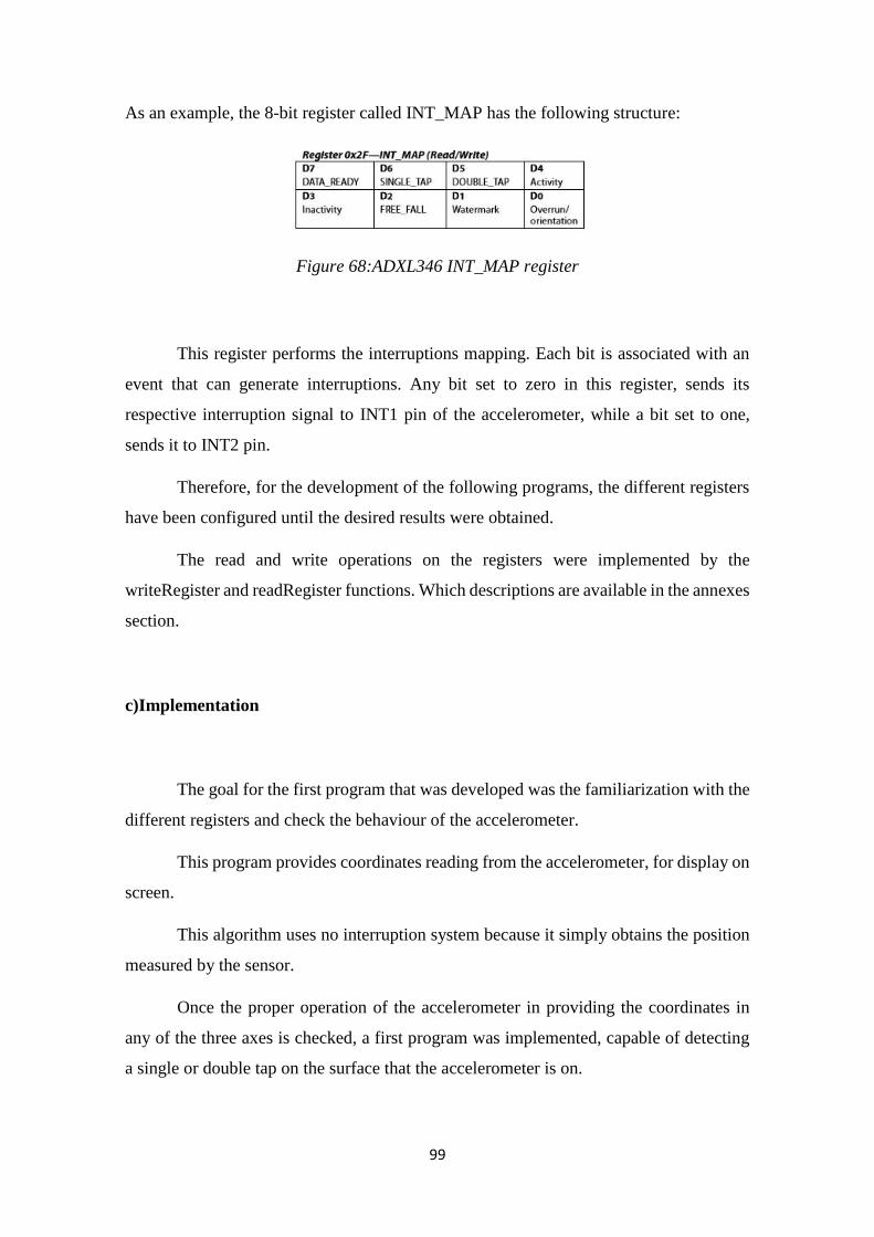
99
As an example, the 8-bit register called INT_MAP has the following structure:
Figure 68:ADXL346 INT_MAP register
This register performs the interruptions mapping. Each bit is associated with an
event that can generate interruptions. Any bit set to zero in this register, sends its
respective interruption signal to INT1 pin of the accelerometer, while a bit set to one,
sends it to INT2 pin.
Therefore, for the development of the following programs, the different registers
have been configured until the desired results were obtained.
The read and write operations on the registers were implemented by the
writeRegister and readRegister functions. Which descriptions are available in the annexes
section.
c)Implementation
The goal for the first program that was developed was the familiarization with the
different registers and check the behaviour of the accelerometer.
This program provides coordinates reading from the accelerometer, for display on
screen.
This algorithm uses no interruption system because it simply obtains the position
measured by the sensor.
Once the proper operation of the accelerometer in providing the coordinates in
any of the three axes is checked, a first program was implemented, capable of detecting
a single or double tap on the surface that the accelerometer is on.
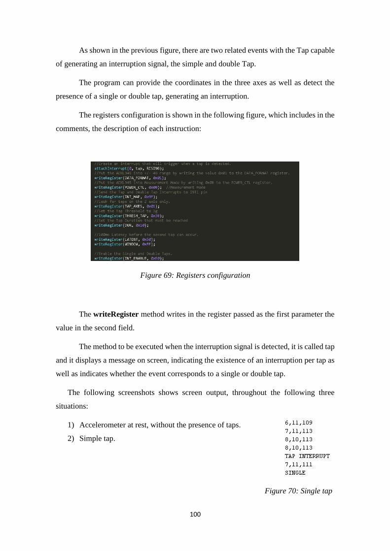
100
As shown in the previous figure, there are two related events with the Tap capable
of generating an interruption signal, the simple and double Tap.
The program can provide the coordinates in the three axes as well as detect the
presence of a single or double tap, generating an interruption.
The registers configuration is shown in the following figure, which includes in the
comments, the description of each instruction:
Figure 69: Registers configuration
The writeRegister method writes in the register passed as the first parameter the
value in the second field.
The method to be executed when the interruption signal is detected, it is called tap
and it displays a message on screen, indicating the existence of an interruption per tap as
well as indicates whether the event corresponds to a single or double tap.
The following screenshots shows screen output, throughout the following three
situations:
1) Accelerometer at rest, without the presence of taps.
2) Simple tap.
Figure 70: Single tap
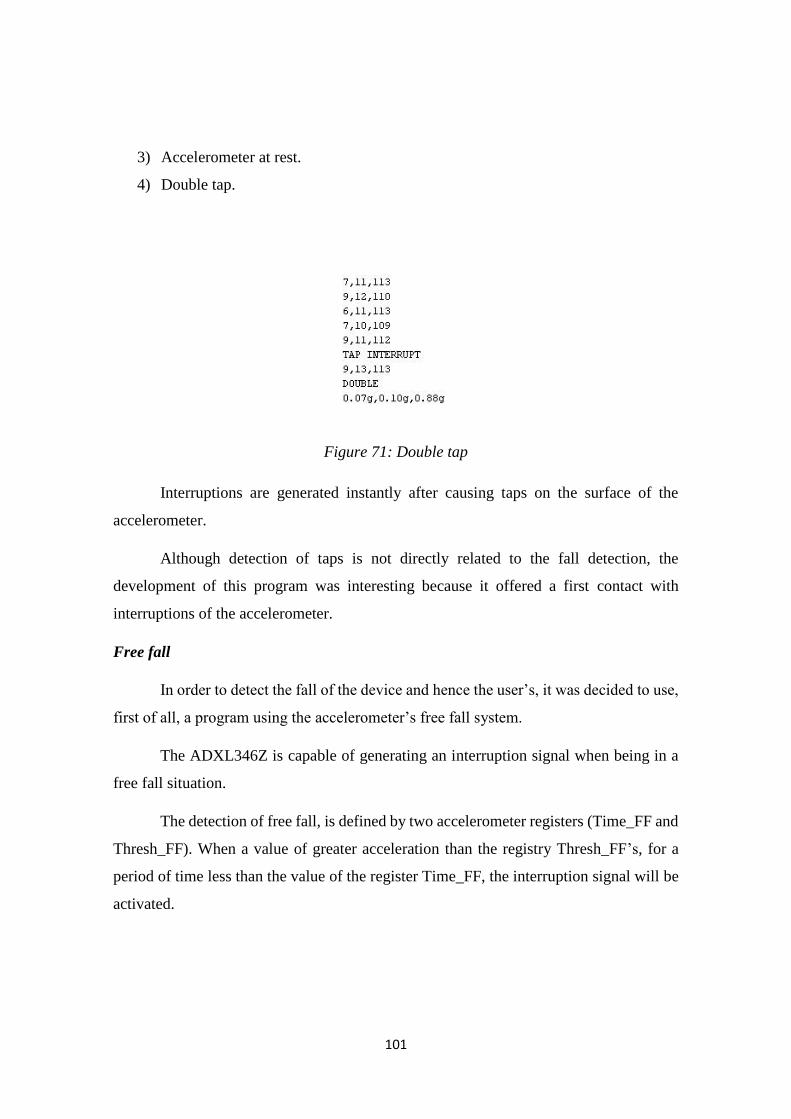
101
3) Accelerometer at rest.
4) Double tap.
Figure 71: Double tap
Interruptions are generated instantly after causing taps on the surface of the
accelerometer.
Although detection of taps is not directly related to the fall detection, the
development of this program was interesting because it offered a first contact with
interruptions of the accelerometer.
Free fall
In order to detect the fall of the device and hence the user’s, it was decided to use,
first of all, a program using the accelerometer’s free fall system.
The ADXL346Z is capable of generating an interruption signal when being in a
free fall situation.
The detection of free fall, is defined by two accelerometer registers (Time_FF and
Thresh_FF). When a value of greater acceleration than the registry Thresh_FF’s, for a
period of time less than the value of the register Time_FF, the interruption signal will be
activated.
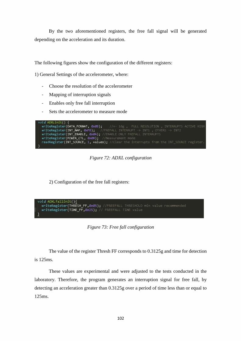
102
By the two aforementioned registers, the free fall signal will be generated
depending on the acceleration and its duration.
The following figures show the configuration of the different registers:
1) General Settings of the accelerometer, where:
- Choose the resolution of the accelerometer
- Mapping of interruption signals
- Enables only free fall interruption
- Sets the accelerometer to measure mode
Figure 72: ADXL configuration
2) Configuration of the free fall registers:
Figure 73: Free fall configuration
The value of the register Thresh FF corresponds to 0.3125g and time for detection
is 125ms.
These values are experimental and were adjusted to the tests conducted in the
laboratory. Therefore, the program generates an interruption signal for free fall, by
detecting an acceleration greater than 0.3125g over a period of time less than or equal to
125ms.
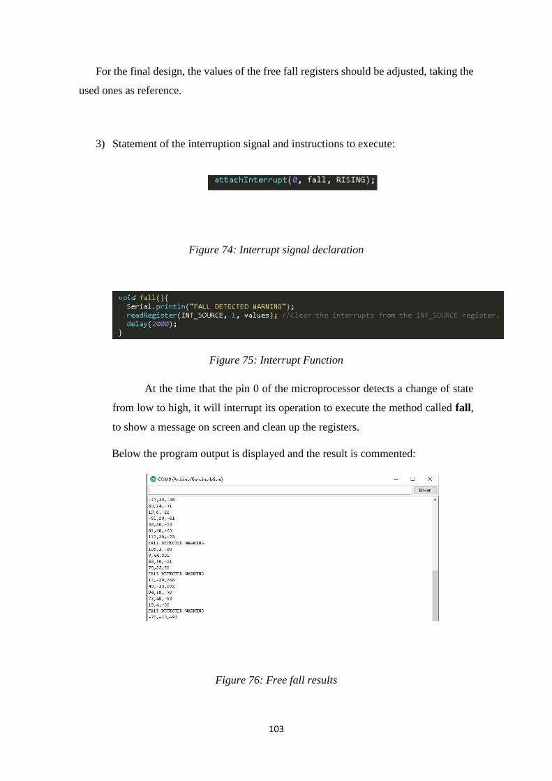
103
For the final design, the values of the free fall registers should be adjusted, taking the
used ones as reference.
3) Statement of the interruption signal and instructions to execute:
Figure 74: Interrupt signal declaration
Figure 75: Interrupt Function
At the time that the pin 0 of the microprocessor detects a change of state
from low to high, it will interrupt its operation to execute the method called fall,
to show a message on screen and clean up the registers.
Below the program output is displayed and the result is commented:
Figure 76: Free fall results
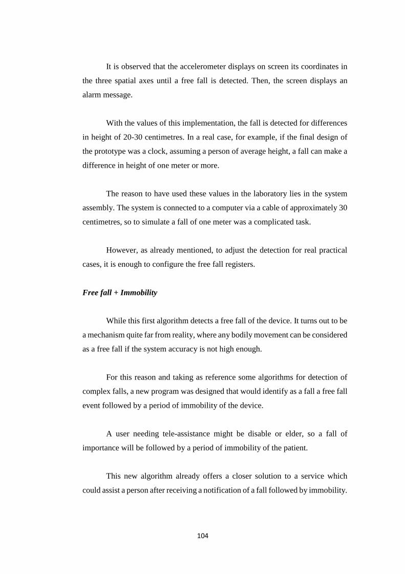
104
It is observed that the accelerometer displays on screen its coordinates in
the three spatial axes until a free fall is detected. Then, the screen displays an
alarm message.
With the values of this implementation, the fall is detected for differences
in height of 20-30 centimetres. In a real case, for example, if the final design of
the prototype was a clock, assuming a person of average height, a fall can make a
difference in height of one meter or more.
The reason to have used these values in the laboratory lies in the system
assembly. The system is connected to a computer via a cable of approximately 30
centimetres, so to simulate a fall of one meter was a complicated task.
However, as already mentioned, to adjust the detection for real practical
cases, it is enough to configure the free fall registers.
Free fall + Immobility
While this first algorithm detects a free fall of the device. It turns out to be
a mechanism quite far from reality, where any bodily movement can be considered
as a free fall if the system accuracy is not high enough.
For this reason and taking as reference some algorithms for detection of
complex falls, a new program was designed that would identify as a fall a free fall
event followed by a period of immobility of the device.
A user needing tele-assistance might be disable or elder, so a fall of
importance will be followed by a period of immobility of the patient.
This new algorithm already offers a closer solution to a service which
could assist a person after receiving a notification of a fall followed by immobility.
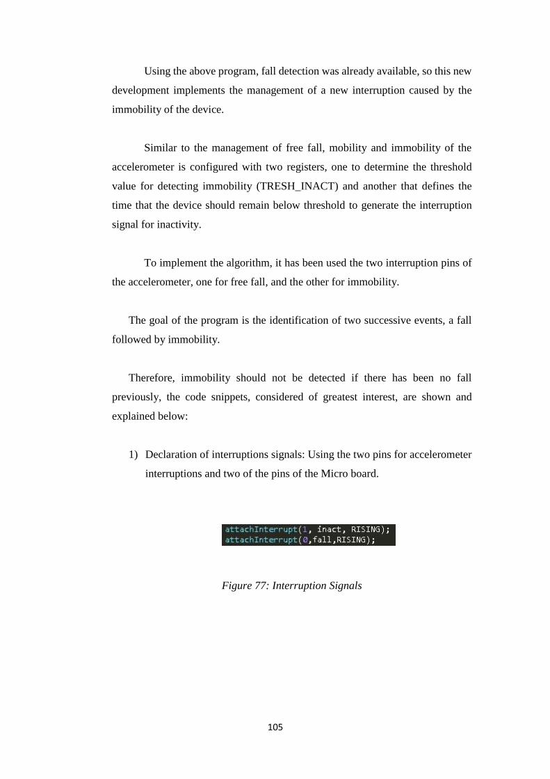
105
Using the above program, fall detection was already available, so this new
development implements the management of a new interruption caused by the
immobility of the device.
Similar to the management of free fall, mobility and immobility of the
accelerometer is configured with two registers, one to determine the threshold
value for detecting immobility (TRESH_INACT) and another that defines the
time that the device should remain below threshold to generate the interruption
signal for inactivity.
To implement the algorithm, it has been used the two interruption pins of
the accelerometer, one for free fall, and the other for immobility.
The goal of the program is the identification of two successive events, a fall
followed by immobility.
Therefore, immobility should not be detected if there has been no fall
previously, the code snippets, considered of greatest interest, are shown and
explained below:
1) Declaration of interruptions signals: Using the two pins for accelerometer
interruptions and two of the pins of the Micro board.
Figure 77: Interruption Signals

106
2) Initialization of the accelerometer:
-
Figure 78: Accelerometer initialization
The accelerometer is configured so that only free fall detection can generate an
interruption signal.
1) Setting the parameters of inactivity:
Figure 79: Inact registers configuration
By writing the values shown in the registers of inactivity, a threshold value
is obtained corresponding to 0.1875g and a downtime of 10 seconds.
These values are quite suitable for experimentation, since acceleration is
small enough to only be activated in case of practically zero inactivity or
mobility, and 10 seconds is a period of high enough time for the user to resume
his activity, if the fall was mild and without assistance.
2) Management of interruptions:
Figure 80: Interrupt functions
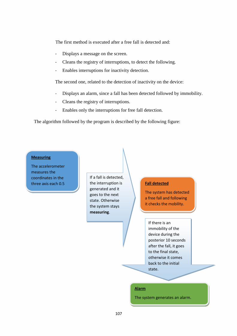
107
The first method is executed after a free fall is detected and:
- Displays a message on the screen.
- Cleans the registry of interruptions, to detect the following.
- Enables interruptions for inactivity detection.
The second one, related to the detection of inactivity on the device:
- Displays an alarm, since a fall has been detected followed by immobility.
- Cleans the registry of interruptions.
- Enables only the interruptions for free fall detection.
The algorithm followed by the program is described by the following figure:
Measuring
The accelerometer
measures the
coordinates in the
three axis each 0.5
seconds.
If a fall is detected,
the interruption is
generated and it
goes to the next
state. Otherwise
the system stays
measuring.
Fall detected
The system has detected
a free fall and following
it checks the mobility.
If there is an
immobility of the
device during the
posterior 10 seconds
after the fall, it goes
to the final state,
otherwise it comes
back to the initial
state.
Alarm
The system generates an alarm.
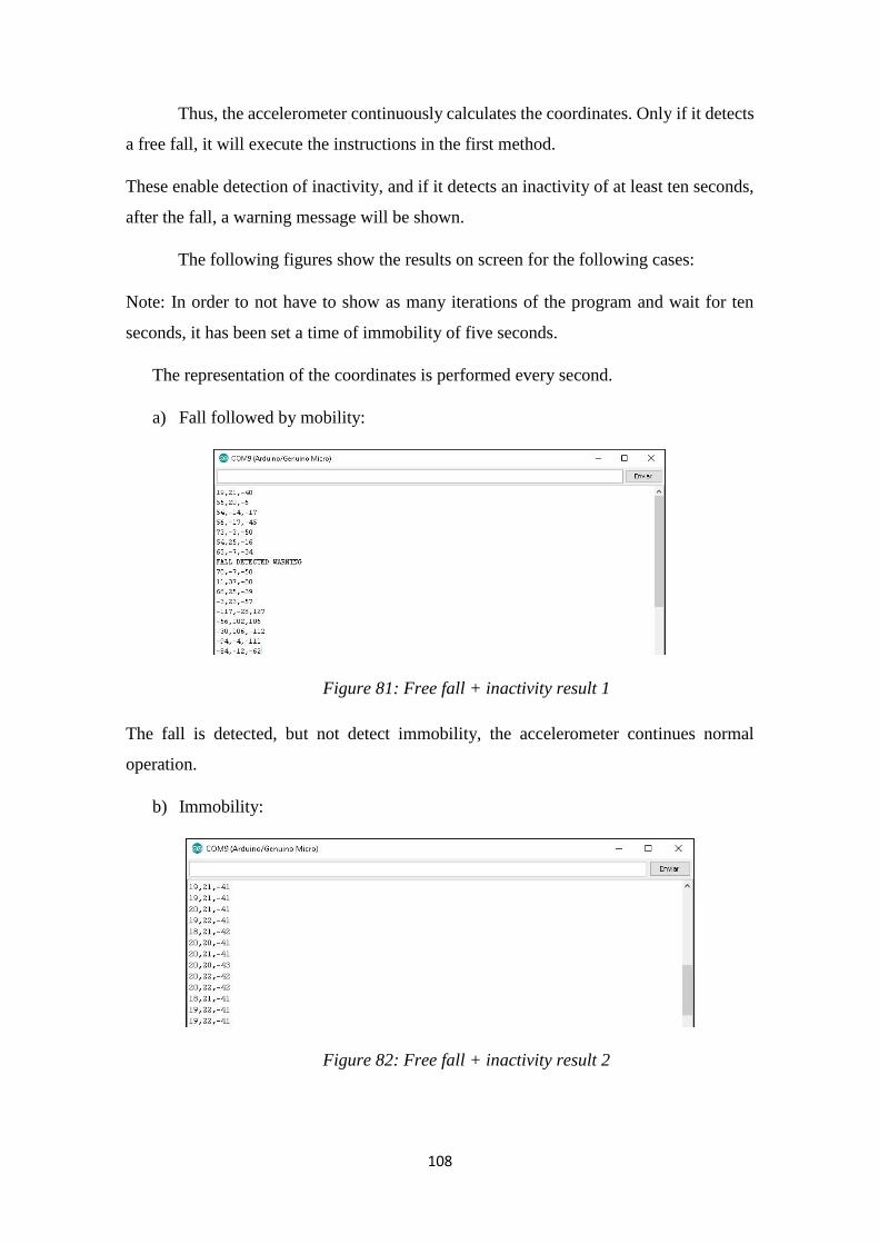
108
Thus, the accelerometer continuously calculates the coordinates. Only if it detects
a free fall, it will execute the instructions in the first method.
These enable detection of inactivity, and if it detects an inactivity of at least ten seconds,
after the fall, a warning message will be shown.
The following figures show the results on screen for the following cases:
Note: In order to not have to show as many iterations of the program and wait for ten
seconds, it has been set a time of immobility of five seconds.
The representation of the coordinates is performed every second.
a) Fall followed by mobility:
Figure 81: Free fall + inactivity result 1
The fall is detected, but not detect immobility, the accelerometer continues normal
operation.
b) Immobility:
Figure 82: Free fall + inactivity result 2
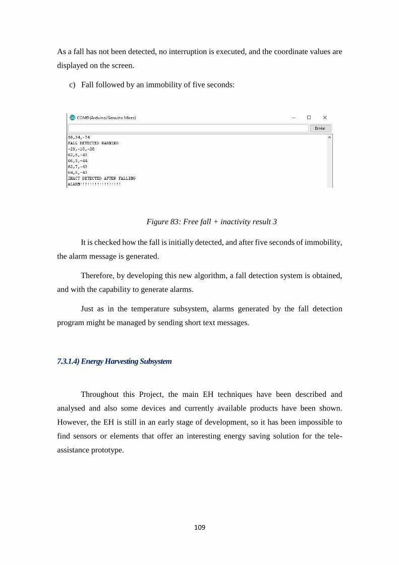
109
As a fall has not been detected, no interruption is executed, and the coordinate values are
displayed on the screen.
c) Fall followed by an immobility of five seconds:
Figure 83: Free fall + inactivity result 3
It is checked how the fall is initially detected, and after five seconds of immobility,
the alarm message is generated.
Therefore, by developing this new algorithm, a fall detection system is obtained,
and with the capability to generate alarms.
Just as in the temperature subsystem, alarms generated by the fall detection
program might be managed by sending short text messages.
7.3.1.4) Energy Harvesting Subsystem
Throughout this Project, the main EH techniques have been described and
analysed and also some devices and currently available products have been shown.
However, the EH is still in an early stage of development, so it has been impossible to
find sensors or elements that offer an interesting energy saving solution for the tele-
assistance prototype.
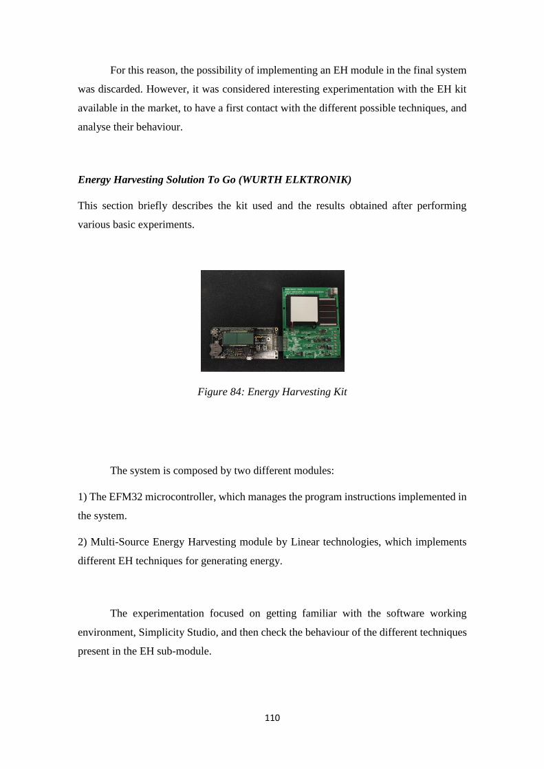
110
For this reason, the possibility of implementing an EH module in the final system
was discarded. However, it was considered interesting experimentation with the EH kit
available in the market, to have a first contact with the different possible techniques, and
analyse their behaviour.
Energy Harvesting Solution To Go (WURTH ELKTRONIK)
This section briefly describes the kit used and the results obtained after performing
various basic experiments.
Figure 84: Energy Harvesting Kit
The system is composed by two different modules:
1) The EFM32 microcontroller, which manages the program instructions implemented in
the system.
2) Multi-Source Energy Harvesting module by Linear technologies, which implements
different EH techniques for generating energy.
The experimentation focused on getting familiar with the software working
environment, Simplicity Studio, and then check the behaviour of the different techniques
present in the EH sub-module.
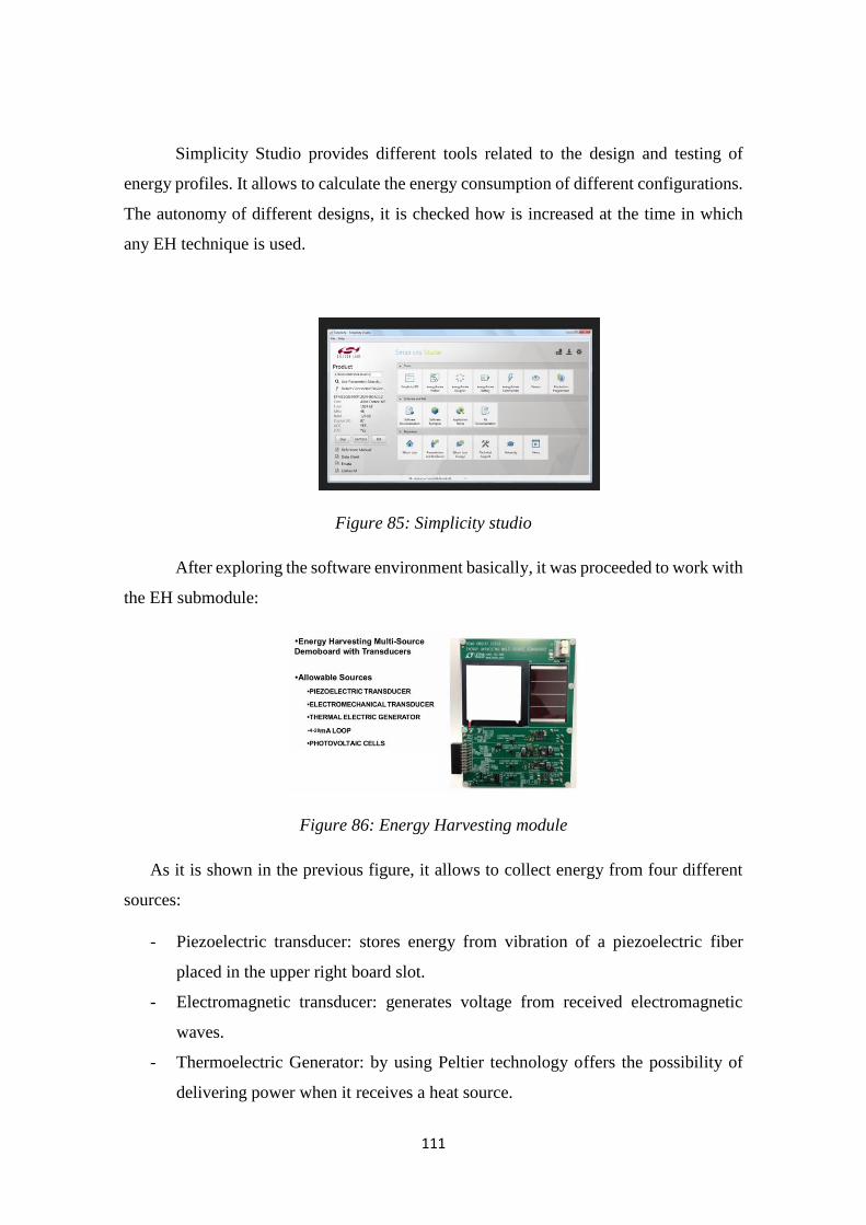
111
Simplicity Studio provides different tools related to the design and testing of
energy profiles. It allows to calculate the energy consumption of different configurations.
The autonomy of different designs, it is checked how is increased at the time in which
any EH technique is used.
Figure 85: Simplicity studio
After exploring the software environment basically, it was proceeded to work with
the EH submodule:
Figure 86: Energy Harvesting module
As it is shown in the previous figure, it allows to collect energy from four different
sources:
- Piezoelectric transducer: stores energy from vibration of a piezoelectric fiber
placed in the upper right board slot.
- Electromagnetic transducer: generates voltage from received electromagnetic
waves.
- Thermoelectric Generator: by using Peltier technology offers the possibility of
delivering power when it receives a heat source.
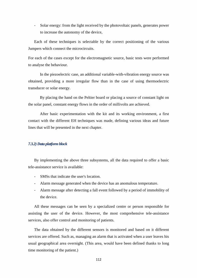
112
- Solar energy: from the light received by the photovoltaic panels, generates power
to increase the autonomy of the device,
Each of these techniques is selectable by the correct positioning of the various
Jumpers which connect the microcircuits.
For each of the cases except for the electromagnetic source, basic tests were performed
to analyse the behaviour.
In the piezoelectric case, an additional variable-with-vibration energy source was
obtained, providing a more irregular flow than in the case of using thermoelectric
transducer or solar energy.
By placing the hand on the Peltier board or placing a source of constant light on
the solar panel, constant energy flows in the order of millivolts are achieved.
After basic experimentation with the kit and its working environment, a first
contact with the different EH techniques was made, defining various ideas and future
lines that will be presented in the next chapter.
7.3.2) Data platform block
By implementing the above three subsystems, all the data required to offer a basic
tele-assistance service is available:
- SMSs that indicate the user's location.
- Alarm message generated when the device has an anomalous temperature.
- Alarm message after detecting a fall event followed by a period of immobility of
the device.
All these messages can be seen by a specialized centre or person responsible for
assisting the user of the device. However, the most comprehensive tele-assistance
services, also offer control and monitoring of patients.
The data obtained by the different sensors is monitored and based on it different
services are offered. Such as, managing an alarm that is activated when a user leaves his
usual geographical area overnight. (This area, would have been defined thanks to long
time monitoring of the patient.)

113
In addition to the goal of providing a monitoring service, it is interesting that the IoT
prototype may be able to connect to other devices or to store data collected over time in
a database.
As explained throughout the chapter of Architecture and Technology, a platform
capable of storing the parameters measured by the sensors would allow the
implementation of new features and services for tele-assistance.
Once the data is stored, it would be possible to implement an application to interpret,
represent or perform actions on it.
To address this point, a subsystem called Data platform is developed.
The implementation of this subsystem provides for the connection of different
sensors, with an existing data platform, which will receive and store the different data that
the prototype is capable of measuring.
It was decided to take advantage of an existing data platform called Flubber, which
basic description is given in the following point:
7.3.2.1) Flubber platform
7.3.2.1.1) Introduction
IoD platform (internet of data) that allows the interconnection of different
components storing data sent by them. It supports connection of sensors, mobile
applications and wearable devices, among others.
Figure 87:Flubber logo
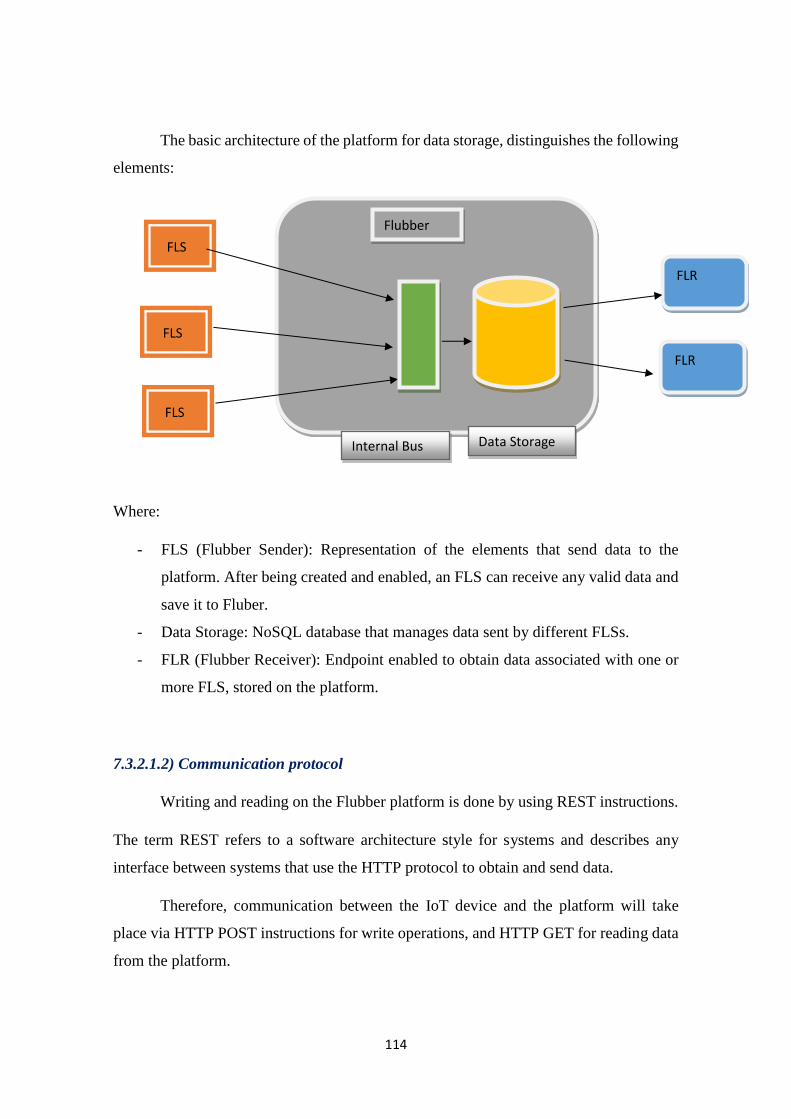
114
The basic architecture of the platform for data storage, distinguishes the following
elements:
Where:
- FLS (Flubber Sender): Representation of the elements that send data to the
platform. After being created and enabled, an FLS can receive any valid data and
save it to Fluber.
- Data Storage: NoSQL database that manages data sent by different FLSs.
- FLR (Flubber Receiver): Endpoint enabled to obtain data associated with one or
more FLS, stored on the platform.
7.3.2.1.2) Communication protocol
Writing and reading on the Flubber platform is done by using REST instructions.
The term REST refers to a software architecture style for systems and describes any
interface between systems that use the HTTP protocol to obtain and send data.
Therefore, communication between the IoT device and the platform will take
place via HTTP POST instructions for write operations, and HTTP GET for reading data
from the platform.
FLS
FLS
FLS
Flubber
Data Storage Internal Bus
FLR
FLR
115
7.3.2.1.3 )Data format
The data sent by the device to the platform is in the JSON format. This lightweight
text format allows the use of numbers, strings, vectors and objects among others.
Each JSON object should contain the following fields:
- senderUid: Contains the identification of a FLS, which is automatically generated
by the platform. It has a string format.
- createdAt: Field indicating the object creation time (UNIX timestamp format).
- Value: The JSON object with the parameters that will be sent. It will follow a
scheme determined by the user, at the time of defining the FLS.
7.3.2.1.4) Security protocol
The platform ensures a secure connection by using the OAuth 2.0 token-based protocol.
When creating a FLS, in addition to automatically obtain an identification field to send
the data, the platform provides a token, responsible for authorizing communication
between the sensor and the platform.
This token must be included in the header of the data sent to the platform, in the way that
will be explained in the implementation section.
Using the following schema, it is intended to summarize the steps for sending data
correctly to the platform.
The part of creating an FLR and an application that can get the stored data from a FLS,
has been discarded since the objective of experimenting with the FLUBBER platform
was focused on sending data and its storage. The data retrieval was left for future
experiments.
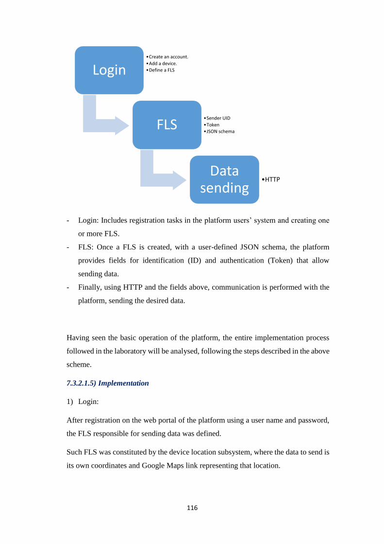
116
- Login: Includes registration tasks in the platform users’ system and creating one
or more FLS.
- FLS: Once a FLS is created, with a user-defined JSON schema, the platform
provides fields for identification (ID) and authentication (Token) that allow
sending data.
- Finally, using HTTP and the fields above, communication is performed with the
platform, sending the desired data.
Having seen the basic operation of the platform, the entire implementation process
followed in the laboratory will be analysed, following the steps described in the above
scheme.
7.3.2.1.5) Implementation
1) Login:
After registration on the web portal of the platform using a user name and password,
the FLS responsible for sending data was defined.
Such FLS was constituted by the device location subsystem, where the data to send is
its own coordinates and Google Maps link representing that location.
Login •Create an account.
•Add a device.
•Define a FLS
FLS•Sender UID
•Token
•JSON schema
Data sending
•HTTP
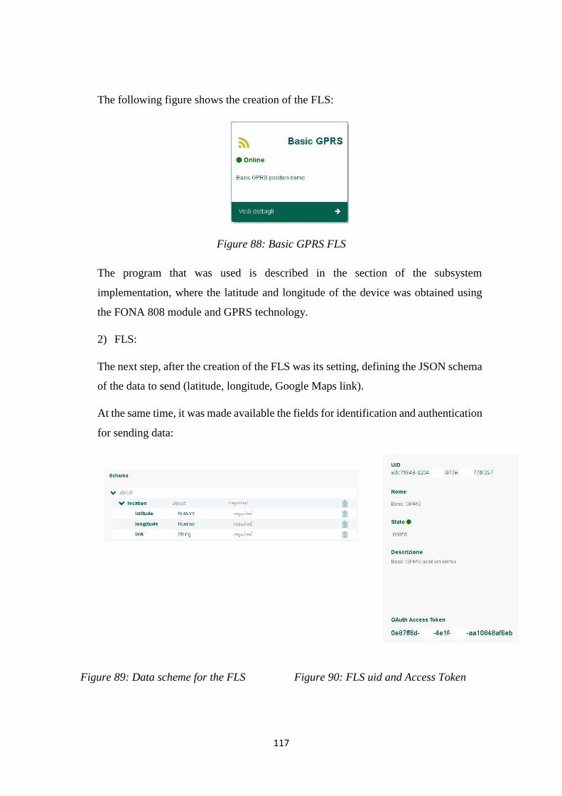
117
The following figure shows the creation of the FLS:
Figure 88: Basic GPRS FLS
The program that was used is described in the section of the subsystem
implementation, where the latitude and longitude of the device was obtained using
the FONA 808 module and GPRS technology.
2) FLS:
The next step, after the creation of the FLS was its setting, defining the JSON schema
of the data to send (latitude, longitude, Google Maps link).
At the same time, it was made available the fields for identification and authentication
for sending data:
Figure 89: Data scheme for the FLS Figure 90: FLS uid and Access Token

118
Therefore, the program that obtains the location of the prototype, was modified
by adding the JSON objects in accordance with the previous figure.
It should be mentioned, as stated in the section Data format, in addition to the
schema shown, the senderUid and createdAt fields must be added.
Therefore, the object to be sent by the device should have the following structure:
The identification of the FLS is automatically obtained from the platform, so it is
a known field.
Obtaining the timestamp was implemented using the fona.enableNTPTimeSync
function found in the library of FONA module that allows real-time synchronization using
NTP network protocol. The format had to be transformed to unix timestamp format using
the following piece of code:
Figure 91: UNIX timestamp code
JSON
Sender UID
ID
Created At
Unix time
Value
- Latitude
-Longitude
-Google Maps link
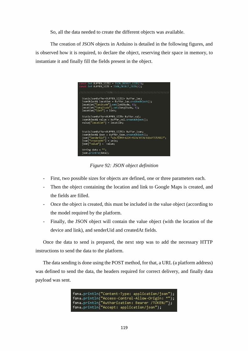
119
So, all the data needed to create the different objects was available.
The creation of JSON objects in Arduino is detailed in the following figures, and
is observed how it is required, to declare the object, reserving their space in memory, to
instantiate it and finally fill the fields present in the object.
Figure 92: JSON object definition
- First, two possible sizes for objects are defined, one or three parameters each.
- Then the object containing the location and link to Google Maps is created, and
the fields are filled.
- Once the object is created, this must be included in the value object (according to
the model required by the platform.
- Finally, the JSON object will contain the value object (with the location of the
device and link), and senderUid and createdAt fields.
Once the data to send is prepared, the next step was to add the necessary HTTP
instructions to send the data to the platform.
The data sending is done using the POST method, for that, a URL (a platform address)
was defined to send the data, the headers required for correct delivery, and finally data
payload was sent.
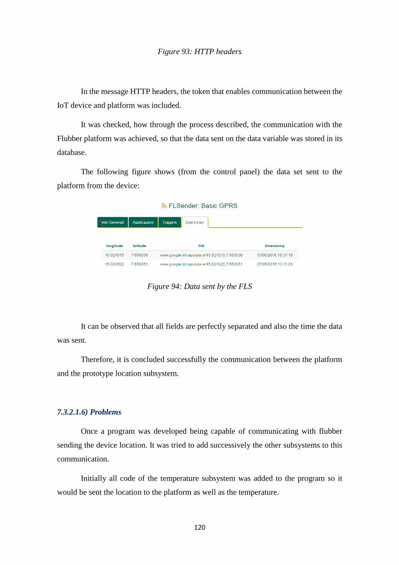
120
Figure 93: HTTP headers
In the message HTTP headers, the token that enables communication between the
IoT device and platform was included.
It was checked, how through the process described, the communication with the
Flubber platform was achieved, so that the data sent on the data variable was stored in its
database.
The following figure shows (from the control panel) the data set sent to the
platform from the device:
Figure 94: Data sent by the FLS
It can be observed that all fields are perfectly separated and also the time the data
was sent.
Therefore, it is concluded successfully the communication between the platform
and the prototype location subsystem.
7.3.2.1.6) Problems
Once a program was developed being capable of communicating with flubber
sending the device location. It was tried to add successively the other subsystems to this
communication.
Initially all code of the temperature subsystem was added to the program so it
would be sent the location to the platform as well as the temperature.
121
When attempting to check the results of the new program, a memory problem on
the Arduino board was found, in this case the Arduino Uno. When compiling the entire
program, a message warning that the memory size reached could cause instability
problems. These problems manifested after running the program showing meaningless
messages and ultimately the incorrect execution of the implemented instructions.
For smaller boards, Arduino Micro and Nano, instability problems were not found,
as execution was prevented since more than 100% of available memory was surpassed.
In an attempt to solve this memory problem, it was experimented using the
Arduino board which has better memory capabilities than all mentioned boards.
Unfortunately, this new board has a different microprocessor and new technology,
which results in incorrect interpretation of instructions implemented in the programs.
These problems can be solved in the future, with the forthcoming software updates of the
board 101. Therefore, it cannot be achieved a satisfactory communication including the
temperature subsystem.
7.3.3) Application block
The last subsystem in the architecture of the tele-assistance prototype, it is
intended to be able to obtain and interpret the data stored in a database.
By using the Flubber platform, it was possible to send all information related to
the location and a Google Maps link.
During experimentation, it was decided to leave the implementation of a proper
application for future designs. Seizing at the moment, the existence of any application
that could interpret the offered data.
Throughout the whole process, the usefulness of Google Maps application is
recognized, to display the device's location on a map, easily and clearly. Therefore it was
decided to simply check, once the data is stored on the platform, how the link to the
Google Maps application can be obtained through the HTTP GET method, and display
the position of the device on a map, identically to the results obtained by sending the
position via SMS.

122
Due to time constraints, one FLR associated with the previous FLS was created
and defined, leaving for future designs the implementation of a program to get the google
map link field from the data stored on the platform (using the HTTP GET method).
Just as for a FLS, the application presents the fields of identification and
authentication to ensure secure and unambiguous connection between the platform and
the application.
The implementation of the different subsystems of the prototype finished after
performing the above experiments.
In the next chapter, an analysis of the results will be done to check whether this
project’s desired objectives were achieved.
8) Evaluation
The objective of this section is to review and assess the results obtained, in
addition to present the points to improve or could not be implemented in this first tele-
assistance prototype.
To make that balance, firstly, the initial objectives of this project will be addressed:
- First contact and scouting of different EH techniques.
- Improvement of the Adamo tele-assistance system, offering outdoor capacity.
- Design of a small-size prototype to facilitate its insertion into the users’ life.
Figure 95: FLR application
123
8.1)EH
Throughout this paper, there have been several approaches to EH term and its
current situation. Initially, there has been explained the meaning of that term and the main
techniques in which it relies to obtain additional energy. Also an analysis was performed
related to the current state of the different investigations and projects which manifested
the initial development state that still have all EH techniques.
It was observed, as one of the main problems in finding products in the market,
the lack of a standard regarding the technical specifications of the elements, thus
preventing a rigorous comparison between them to choose the most suitable for the
desired application.
Finally, some existing devices and solutions using some EH techniques were
shown. In addition, a basic experimentation using a test kit was carried out, where it was
observed and analysed practically the behaviour of different EH techniques.
Therefore, through this whole journey, a level of initial knowledge about the EH
concept was achieved, which could be very important in future designs when the different
EH projects, are not in such an early stage.
Throughout the study about EH, it has also been proven that this is especially
interesting to IoT devices and wearable autonomous systems.
It is considered as achieved the goal of the research about energy collection since
from the study done in this project, it has been reached a basic level of knowledge about
the EH which can mark the inclusion of a EH subsystem, in future designs, to the tele-
assistance prototype.
The following list summarizes the obtained data and the points considered as positive
and negative and the problems encountered:
- Knowledge about the term and main techniques.
- Checking the importance of energy saving in wearable devices.
124
- Identification of different techniques that can be used in future designs
(piezoelectricity, energy from light or heat).
- Information on the current status of the projects and some current devices.
- Initial phase of development.
- Lack of standardization of the technical specifications
- Few available and expensive products.
8.2) Tele-assistance system
To make an assessment of tele-assistance service offered by the prototype, it
should be analysed the results obtained by each of the subsystems and as a whole.
The first three subsystems (location, temperature, falls system) offer the desired
data and SMS alarm systems have been implemented for the first two.
Location is obtained by using network technology, based on the principle of
energy saving, compared to satellite technology. The accuracy obtained using GPRS, is
considered sufficient to provide an outdoor tele-assistance service. However, in
emergency situations, or those where mobile network remains saturated (eg an accident
in a football stadium), it might be insufficient to provide quick and effective assistance.
Since these situations are punctual, simply comment that could be interesting, as
long as the battery permits and the design is not affected by increasing its size
disproportionately, to include an additional GPS service which would be activated if the
device is unable to connect to a mobile network. Otherwise, it would continue using
GPRS technology.
The temperature subsystem also reaches a fairly good accuracy for the purposes
of tele-assistance, under normal conditions, that is, the chances that the device is in
extremely high or low temperatures are very small, and by using BMP180 barometer,
both situations would be detected without problems.
In the subsystem temperature, it could also have implemented, by using a simple
temperature sensor, since the other functions of the barometer are not used in this
subsystem. The justification for the use of a barometer, it is behind the intention to use
the barometer for detecting falls. In this way, two different subsystems could be
implemented in the same device.

125
As observed during the implementation, it was not possible to use a barometer for
detecting falls, due to insufficient accuracy. Finally, the use of another element, in this
case an accelerometer, was necessary.
The algorithm for fall detection is considered sufficient for a basic tele- assistance
prototype, but most real systems offer a much more complete and real solution to detect
falls, as shown in the following project:
http://www.analog.com/library/analogdialogue/archives/43-07/fall_detector.html
Therefore, even though by using the programs implemented, it is possible to detect
falls, simulated in the laboratory, it has been impossible to check their behaviour in real
situations, with the device placed on a user, so it is unknown if it is sufficient to consider
a fall followed by inactivity as sufficient to generate an alarm.
The developed implementation finished with the combination of the location
subsystem with temperature subsystem, however, the fall detection system did not
become interconnected with the rest.
The reasons were purely technological, because when combining the codes of the
three devices, the memory capacity of the different Arduino boards available in the
laboratory was exceeded. Since the Arduino language and its environment are optimal for
application development and systems as the prototype of this thesis, the problem focuses
on finding a board capable of supporting the code of the three subsystems.
The tests using the Arduino 101 board were performed, but as reported in the
implementation, the instructions do not execute properly, due to the different architecture
present on this board which has more memory.
Therefore, a negative point to mention is the lack of cohesion between the three
subsystems responsible for obtaining the data. It has been possible to get a tele-assistance
module offering the location and temperature of the device and also its system of alarms
via SMS, however, the fall detection system is implemented in another block with another
microprocessor, to check the results.
The problem is solved by finding an Arduino board capable of supporting the full
code (already developed) and run properly. Simply connect the three elements to the
microprocessor of the Arduino board, and thus a more complete tele-assistance service
would be available.
126
The objective set by the tele-assistance service has been achieved, given that the
prototype is able to offer (without fall detection subsystem, due to the problem presented)
an outdoor assistance service and alarm system that works efficiently using SMSs.
Therefore, this prototype serves as a baseline for the exploration and development
of Adamo system, for outdoor areas and implemented using an autonomous and wearable
design.
Furthermore, it has been proven that the device is an open system able to
communicate with a database easily. Using this communication with data platforms, new
possibilities are opened to provide the service and alarm management. (Example: a
specialized service that obtains data from a platform to carry out monitoring and control
tasks).
8.3) Design
Although it was not an objective of this thesis to end the development with a final
design that could be placed directly on the user, clear lines of design to be followed by
the prototype and future designs were marked: the size and economic efficiency.
Therefore, most of the modules used (FONA 808, BMP180) are elements of low
power consumption and small size.
Nowadays, the size of the prototype considering the accelerometer, barometer and
locating device, has a similar size to a battery of a mobile phone or a wallet and a
negligible weight, so it is considered as a wearable IoT device, which can be introduced
transparently into a patient's life.
The size is mostly determined by the used Arduino board and the battery, by
reducing both, even smaller dimensions can be achieved.
Again, the prototype defines the starting point after which evolution to obtain a
completely wearable final design is possible.
127
After evaluating the whole process carried out in terms of the objectives set, in the
next points the final conclusions are discussed and the possible future lines are also
described.
9) CONCLUSION
By implementing the various existing modules, it is concluded that a basic tele-
assistance system has been developed which is also managed by short text messages,
without using a fixed terminal connected to the telephone line.
The autonomous prototype ensures indoor and outdoor coverage and a system of
alarms generated by the various sensors. The service is offered via SMS, sending the
location and the generated alarm. The SMSs are also sent to the configured phone number
(s).
Enough knowledge has been obtained about the EH techniques to be able to
implement a module for energy saving in future designs, which would ensure a higher
autonomy of the device and even its use without batteries. It has also been carried out
successful communication with a database that offers a variety of new services for future
designs.
Therefore, there is a tele-assistance prototype defining the starting line, from
which to develop a complete tele-assistance system offering coverage outdoor, and uses
concepts such as EH, the monitoring and ultimately, an autonomous system able to
provide assistance in real time.
128
10) FUTURE LINES
This prototype and the different modules of the system architecture allow us to
define a series of future lines to be followed by similar designs or projects.
EH: Different EH techniques might be used in the near future. The inclusion of a
piezoelectric module or using solar cells, seems really interesting in order to provide a
source of natural and renewable energy for a wearable device. The choice of these depend
on the design (if the design is constantly exposed to light sources, if the design can take
advantage of the user's body motion or vibrations etc.).
Data platform: Using a data platform capable of storing and managing the data
measured by the sensors. In future designs, new monitoring services, user or application
control will be defined which would open the possibility of designing third party
applications to display the data generated by the sensors.
Fall system and other data: As future tasks to improve the service already
provided, it is proposed the improvement of the fall detection system, by developing more
new and comprehensive algorithms. The insertion of new sensors that provide important
parameters for tele-assistance, such as heartbeat, is also proposed.
To conclude, the future lines are marked with a view to progressively improve the
service provided, adding services and making these more efficient in terms of energy
consumption and size.
129
11) REFERENCES
[1] L. Kelvin, “Electrical Units of Measurement’, PLA vol 1, 1883.
12) BIBLIOGRAPHY
INTRODUCCTION
http://publications.paho.org/spanish/PC_590_Tercera_edad.pdf
http://www.msssi.gob.es/profesionales/saludPublica/prevPromocion/docs/caidas.pdf
http://escuela.med.puc.cl/publ/boletin/geriatria/CaidasAdulto.HTML
http://salud.ccm.net/faq/3434-las-caidas-en-los-ancianos
http://www.bvs.sld.cu/revistas/mgi/vol15_1_99/mgi11199.htm
ARDUINO
https://www.arduino.cc/en/Guide/Environment
https://www.arduino.cc/en/Guide/HomePage
https://www.arduino.cc/en/Guide/Libraries
https://www.arduino.cc/en/Reference/HomePage
https://es.wikipedia.org/wiki/Arduino#Lenguaje_de_programaci.C3.B3n_Arduino
http://www.prometec.net/interrupciones/
https://www.arduino.cc/en/Reference/Interrupts
https://www.arduino.cc/en/Reference/AttachInterrupt
FONA
https://learn.adafruit.com/adafruit-fona-mini-gsm-gprs-cellular-phone-module/fona-808-vs-
fona-800
https://learn.adafruit.com/adafruit-fona-mini-gsm-gprs-cellular-phone-module/overview
https://www.adafruit.com/product/2636

130
JSON
https://github.com/bblanchon/ArduinoJson/wiki/Memory%20model
https://github.com/bblanchon/ArduinoJson/wiki/Encoding-JSON
ADXL346 ACELEROMETER
https://www.sparkfun.com/tutorials/240
FALLS
http://www.paho.org/hq/index.php?option=com_content&view=article&id=6615%3A2012-
mortalidad-causas-defuncion-adultos-mayores&catid=2390%3Arho-
themes&Itemid=2391&lang=es
ENERGY HARVESTING & INTERNET OF THINGS ENERGY EFFICIENCY
http://www.iop.org/resources/energy/
http://ubiquity.acm.org/article.cfm?id=2822887
http://www.govtech.com/fs/news/The-Internet-of-Things-Will-Thrive-On-Energy-Efficiency-
.html
http://www.energymanagertoday.com/energy-management-the-internet-of-things-changes-
everything-0120273/
http://www.engerati.com/article/internet-things-eats-energy-efficiency
http://spectrum.ieee.org/consumer-electronics/gadgets/three-technologies-for-harvesting-
ambient-energy
https://www.theguardian.com/sustainable-business/2016/feb/04/harvesting-energy-humans-
walking-charge-wearables-bending-mit
https://www.wearable-technologies.com/2015/07/energy-harvesting-technology-can-be-the-
wave-of-the-future/
https://www.wearable-technologies.com/2016/02/2016-news-in-energy-harvesting/
http://engineering.illinois.edu/news/article/8445
SILICON LABS
http://www.silabs.com/Pages/default.aspx
http://www.silabs.com/products/mcu/Pages/default.aspx
http://www.solepowertech.com/ensoles/
STATE OF ART
http://gpssmartsole.com/gpssmartsole/
http://safelinkgps.com/
https://web.whatsapp.com/
http://pocketfinder.com/
131
https://www.accuware.com/
http://geo.band/
http://www.smarttracksl.com/smart_source/2_products_gps.html
http://www.aditechsrl.it/healthcare/mobile-care/i-help
http://www.mindme.care/
http://www.adamo-vita.it/
http://www.getampy.com/
http://www.linear.com/
http://www.solepowertech.com/ensoles/
http://www.k3ops.com/en/
GPRS & GPS
http://www.liveviewgps.com/blog/what-is-gprs-and-how-is-it-used-with-gps-tracking-devices/
https://es.wikipedia.org/wiki/Sistema_global_de_navegaci%C3%B3n_por_sat%C3%A9lite#NA
VSTAR-GPS
https://es.wikipedia.org/wiki/Unidad_de_seguimiento_GPS
https://es.wikipedia.org/wiki/Sistema_global_de_navegaci%C3%B3n_por_sat%C3%A9lite
https://es.wikipedia.org/wiki/Localizaci%C3%B3n_GSM
https://es.wikipedia.org/wiki/Sistema_global_de_navegaci%C3%B3n_por_sat%C3%A9lite#Te
or.C3.ADa_y_caracter.C3.ADsticas_fundamentales
https://es.wikipedia.org/wiki/Sistema_de_posicionamiento_global#Fuentes_de_error
https://es.wikipedia.org/wiki/Sistema_global_para_las_comunicaciones_m%C3%B3viles#Arqu
itectura_de_red
https://es.wikipedia.org/wiki/Control_de_acceso_al_medio
https://es.wikipedia.org/wiki/Servicio_general_de_paquetes_v%C3%ADa_radio#Servicios_ofre
cidos
https://en.wikipedia.org/wiki/Mobile_phone_tracking
https://en.wikipedia.org/wiki/Cell_ID
https://en.wikipedia.org/wiki/U-TDOA
DATA PLATFOM
http://polaridad.es/almacenar-datos-internet-cosas-IoT/#almacenar-datos-internet-cosas-IoT
https://es.wikipedia.org/wiki/Cliente-servidor
https://es.wikipedia.org/wiki/Servidor_web
132
13) ANNEX
Following, there are listed the links to access to the different datasheets of the devices
used:
ADAFRUIT FONA MANUAL
https://cdn-learn.adafruit.com/downloads/pdf/adafruit-fona-mini-gsm-gprs-cellular-
phone-module.pdf
Barometer BMP180 MANUAL
https://cdn-shop.adafruit.com/datasheets/BST-BMP180-DS000-09.pdf
Barometer BMP280 MANUAL
https://cdn-learn.adafruit.com/downloads/pdf/adafruit-bmp280-barometric-pressure-
plus-temperature-sensor-breakout.pdf
Accelerometer ADXL346 MANUAL
http://pdf1.alldatasheet.com/datasheet-pdf/view/300957/AD/EVAL-ADXL346Z.html
The full code of the different programs implemented along the project are attached in
the next section