a visual notation and an improvement for the syntax of ... · a visual notation and an improvement...
TRANSCRIPT

A Visual Notation and an Improvement for the Syntax
of Larman’s Operation Contracts
by
Abdulaziz Algablan
MCS thesis
This thesis is submitted to the
Faculty of Graduate and Postdoctoral Studies
In partial fulfillment of the requirements for the
Master of Computer Science in Software Engineering
School of Electrical Engineering and Computer Science
Faculty of Engineering
University of Ottawa
Ottawa, Ontario, K1N 6N5
Canada
© Abdulaziz Algablan, Ottawa, Canada 2016

ii
Acknowledgments
Firstly, I would like to thank The Almighty God Allah for giving me this opportunity and
the strength to pursue a post-graduate study in the field of software engineering. Indeed,
this degree has extended my knowledge greatly and has opened new doors for me in the
future.
Secondly, I would like to express my sincere gratitude to my supervisor Dr. Stéphane Somé
for his continuous support during my Master degree. His welcoming spirit, his punctuality,
his patience, and his immense knowledge all helped me to navigate through this journey.
Besides my supervisor, I would like to thank the rest of the defense jury: Dr. Liam Peyton,
and Dr. Jean-Pierre Corriveau, for their remarkable comments. I have learned a lot from
their excellent feedback.
I would like to thank my sponsor in Saudi Arabia, Qassim University, for supporting me
and my family during my study in this wonderful university: the University of Ottawa in
Canada.
I would like to thank my mother, and my father. Your wisdom has enlighten all of my life.
A special thanks to my lovely wife, Wafa. You are always there not only for me, but also
for our two amazing boys: Azzam and Mazen. Thank you to all of my family members
back home, and to all of my friends here and there.
iii
Abstract
System operation contracts were introduced by C. Larman as an application of the notion
of Design by Contract (DbC) to the description of high-level system operations derived
from requirements. A system operation contract specifies an operation in terms of changes
induced in the domain. In the Responsibility Driven Development (RDD) process proposed
by Larman, operation contracts play an important role in identifying and assigning systems'
responsibilities, and help construct a sound design in later phases. Larman's notation for
operation contracts is textual. In this thesis, we propose an alternative visual notation for
operation contracts. As part of the process for the definition of this visual notation, we
extended and clarified some informal aspects of Larman's notation in order to better
accurately capture important aspects of system operations. Our extension allows the
specification of data constraints, alternatives, and the temporal dimension of created
domain objects, in addition to the description of changes in the state and associations of
domain objects. The syntax of the visual notation for operation contracts aims to be
cognitively effective and to reuse available UML notation. New visual elements were
introduced only in the absence of corresponding elements in the UML. Elements reused
from the UML are slightly modified to enhance their cognitive effectiveness. The
introduced elements, on the other hand, are designed with the goal of not conflicting with
the general theme of the UML. We used The Physics of Notations as a general guide and
evaluation criteria. The Physics of Notations is a leading evaluation and design theory for
visual models in software engineering. We propose a prototype tool (ViOpContract) that
implements the proposed visual notation for operation contracts. ViOpContract is an

iv
Eclipse plug-in tool that helps to draw and manage visual operation contracts. The tool
provides the capability to generate contracts in textual form from visual contracts.

v
List of Acronyms
1 The natural acronym would be “WOL”, but the Web-Ontology Working Group named it
“OWL” instead. For more information: https://www.w3.org/2003/08/owlfaq.
ACL : Another Contract Language.
DbC : Design by Contract.
DDD : Domain-Driven Development.
EMF : Eclipse Modeling Framework.
GEF : Graphical Editing Framework.
GRASP : General Responsibility Assignment Software Patterns.
JML : Java Modeling Language.
MDD : Model Driven Development.
MVC : Model-View-Controller.
OCL : Object Constraint Language.
OMG : OMG Object Management Group.
OWL1 : Web Ontology Language.
OVT : Query, View, and Transformation. QVT is a set of model transformation
languages proposed by OMG.
RDD : Responsibility Driven Development.
TRM : Testable Requirements Model.
UML : The Unified Modeling Language.
UP : The Unified Process.
VCL : Visual Contract Language.
VOCL : Visual OCL.
XMI : XML Metadata Interchange.
vi
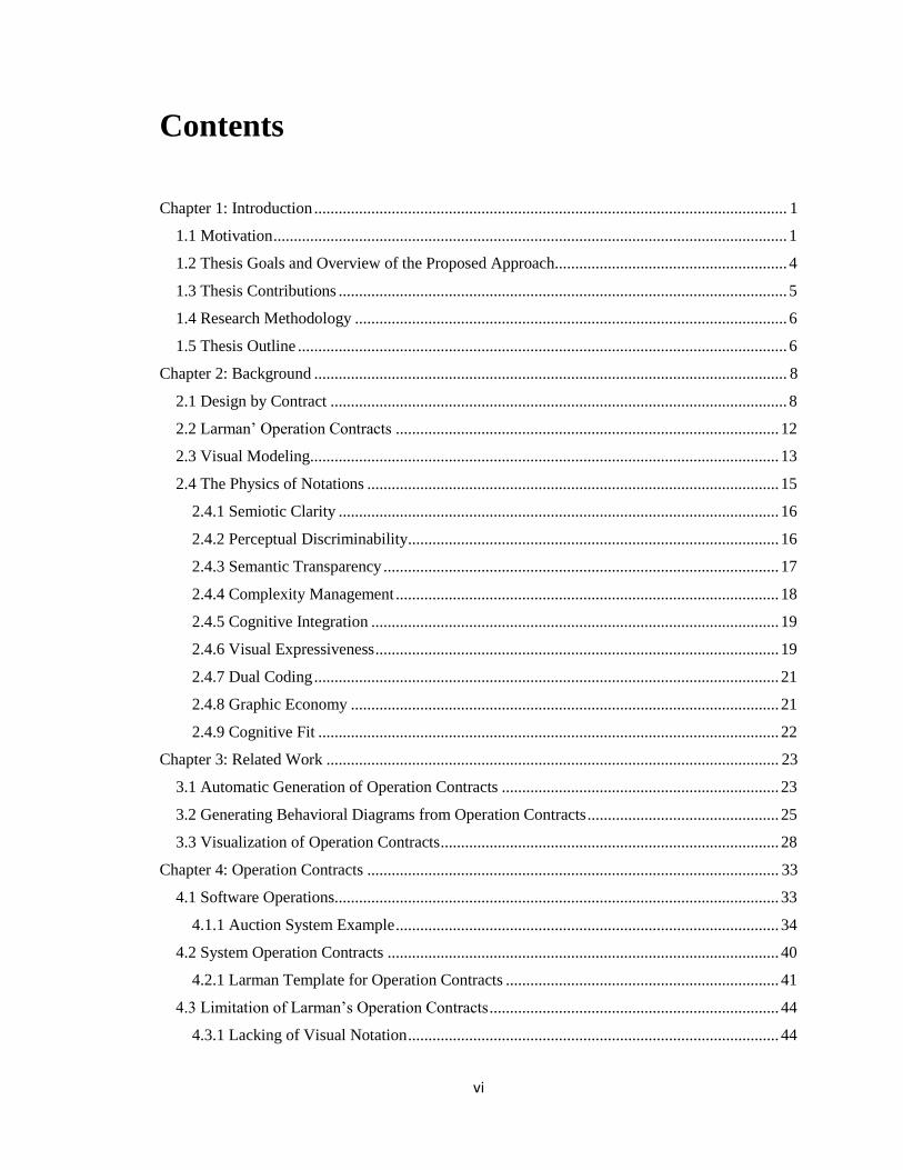
Contents
Chapter 1: Introduction .................................................................................................................... 1
1.1 Motivation .............................................................................................................................. 1
1.2 Thesis Goals and Overview of the Proposed Approach......................................................... 4
1.3 Thesis Contributions .............................................................................................................. 5
1.4 Research Methodology .......................................................................................................... 6
1.5 Thesis Outline ........................................................................................................................ 6
Chapter 2: Background .................................................................................................................... 8
2.1 Design by Contract ................................................................................................................ 8
2.2 Larman’ Operation Contracts .............................................................................................. 12
2.3 Visual Modeling................................................................................................................... 13
2.4 The Physics of Notations ..................................................................................................... 15
2.4.1 Semiotic Clarity ............................................................................................................ 16
2.4.2 Perceptual Discriminability........................................................................................... 16
2.4.3 Semantic Transparency ................................................................................................. 17
2.4.4 Complexity Management .............................................................................................. 18
2.4.5 Cognitive Integration .................................................................................................... 19
2.4.6 Visual Expressiveness ................................................................................................... 19
2.4.7 Dual Coding .................................................................................................................. 21
2.4.8 Graphic Economy ......................................................................................................... 21
2.4.9 Cognitive Fit ................................................................................................................. 22
Chapter 3: Related Work ............................................................................................................... 23
3.1 Automatic Generation of Operation Contracts .................................................................... 23
3.2 Generating Behavioral Diagrams from Operation Contracts ............................................... 25
3.3 Visualization of Operation Contracts ................................................................................... 28
Chapter 4: Operation Contracts ..................................................................................................... 33
4.1 Software Operations............................................................................................................. 33
4.1.1 Auction System Example .............................................................................................. 34
4.2 System Operation Contracts ................................................................................................ 40
4.2.1 Larman Template for Operation Contracts ................................................................... 41
4.3 Limitation of Larman’s Operation Contracts ....................................................................... 44
4.3.1 Lacking of Visual Notation ........................................................................................... 44

vii
4.3.2 The Lack of Constructs for Expressing Data Constraints ............................................. 45
4.3.3 The Lack of Constructs for Describing Temporal and Persistency Aspects of Domain
Objects ................................................................................................................................... 46
4.4 Summary of the Chapter ...................................................................................................... 50
Chapter 5: Visual Operation Contract ............................................................................................ 52
5.1 Motivations of a Visual notation for Larman’s Operation Contracts .................................. 53
5.1.1 Improving the Domain Model....................................................................................... 53
5.1.2 Complementing the Text-based Operation Contracts ................................................... 54
5.1.3 Assist the Writing of the Non-Technical DbC Contracts .............................................. 54
5.2 Improvements to Larman's Contracts .................................................................................. 55
5.2.1 Structuring Syntax for Important Aspects of System Operations ................................. 56
5.2.2 Describing Temporal and Persistency of Domain Objects ........................................... 57
5.3 Visual Operation Contract Notation .................................................................................... 60
5.3.1 An Illustrative Example ................................................................................................ 60
5.3.2 Visual Operation Contract Layout ................................................................................ 64
5.3.3 Visual Components of the Visual Operation Contract .................................................. 65
5.4 The Textual Template of the Visual Operation Contract Notation ...................................... 92
5.5 Visual Operation Contract Meta-Model .............................................................................. 96
5.5.1 Visual Elements Linking Constraints ........................................................................... 97
5.6 Evaluation of the Notation of the Visual Operation Contract .............................................. 98
5.6.1 Semiotic Clarity ............................................................................................................ 99
5.6.2 Perceptual Discriminability......................................................................................... 100
5.6.3 Semantic Transparency ............................................................................................... 103
5.6.4 Complexity Management ............................................................................................ 103
5.6.5 Cognitive Integration .................................................................................................. 104
5.6.6 Visual Expressiveness ................................................................................................. 104
5.6.7 Dual Coding ................................................................................................................ 104
5.6.8 Graphic Economy ....................................................................................................... 105
5.6.9 Cognitive Fit ............................................................................................................... 106
5.7 Related Works Compared to our Visual Operation Contract............................................. 107
5.8 Summary of the Chapter .................................................................................................... 110
Chapter 6: ViOpContract Tool ..................................................................................................... 111
6.1 Overview of the Tool ......................................................................................................... 111
6.2 Domain Model View.......................................................................................................... 112
6.3 System Operation View ..................................................................................................... 115
viii
6.3.1 Adding System Operations ......................................................................................... 116
6.4 Visual Operation Contract View ........................................................................................ 117
6.5 Transformation to Textual Operation Contract .................................................................. 118
6.5.1 Textual Operation Contract Reports ........................................................................... 118
6.5.2 Textual Transformation Algorithm ............................................................................. 119
Chapter 7: Case Study .................................................................................................................. 123
7.1 Sign In Use-Case................................................................................................................ 123
7.1.1 System Sequence Diagram.......................................................................................... 124
7.1.2 SigningIn Visual Operation Contract .......................................................................... 125
7.1.3 Textual Operation Contract for SigningIn .................................................................. 127
7.2 Create Account Use-Case .................................................................................................. 129
7.2.1 System Sequence Diagram.......................................................................................... 130
7.2.2 Visual Operation Contract .......................................................................................... 131
7.2.3 Textual Operation Contract ......................................................................................... 131
7.3 Browse Catalog Use-Case .................................................................................................. 132
7.3.1 System Sequence Diagram.......................................................................................... 133
7.3.2 Visual Operation Contract .......................................................................................... 134
7.3.3 Textual Operation Contract ......................................................................................... 134
7.4 Summary of the Chapter .................................................................................................... 135
Chapter 8: Conclusion.................................................................................................................. 136
8.1 Summary of the Contributions ........................................................................................... 136
8.2 Limitations ......................................................................................................................... 138
8.3 Future Work ....................................................................................................................... 139
ix
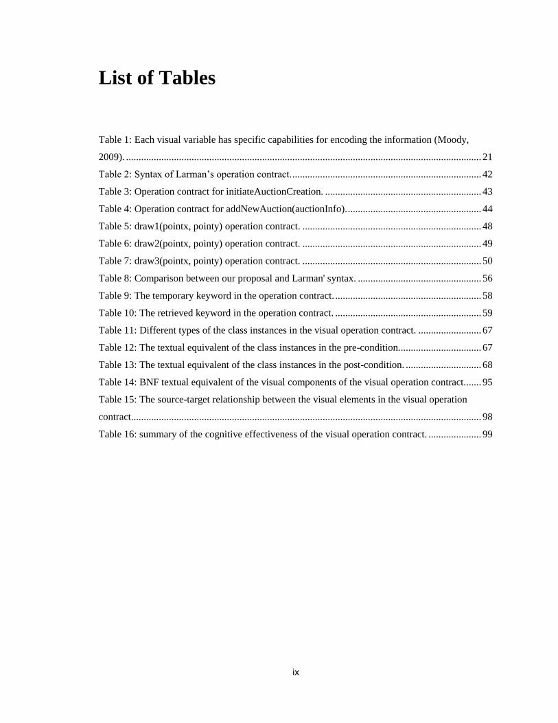
List of Tables
Table 1: Each visual variable has specific capabilities for encoding the information (Moody,
2009). ............................................................................................................................................. 21
Table 2: Syntax of Larman’s operation contract. ........................................................................... 42
Table 3: Operation contract for initiateAuctionCreation. .............................................................. 43
Table 4: Operation contract for addNewAuction(auctionInfo). ..................................................... 44
Table 5: draw1(pointx, pointy) operation contract. ....................................................................... 48
Table 6: draw2(pointx, pointy) operation contract. ....................................................................... 49
Table 7: draw3(pointx, pointy) operation contract. ....................................................................... 50
Table 8: Comparison between our proposal and Larman' syntax. ................................................. 56
Table 9: The temporary keyword in the operation contract. .......................................................... 58
Table 10: The retrieved keyword in the operation contract. .......................................................... 59
Table 11: Different types of the class instances in the visual operation contract. ......................... 67
Table 12: The textual equivalent of the class instances in the pre-condition. ................................ 67
Table 13: The textual equivalent of the class instances in the post-condition. .............................. 68
Table 14: BNF textual equivalent of the visual components of the visual operation contract....... 95
Table 15: The source-target relationship between the visual elements in the visual operation
contract. .......................................................................................................................................... 98
Table 16: summary of the cognitive effectiveness of the visual operation contract. ..................... 99

x
List of Figures
Figure 1: the OCL contract for deposit(amount: Integer). ............................................................. 10
Figure 2: ACL for Container requirements (Arnold et al., 2010). ................................................. 12
Figure 3: The nine principles of the physics of notations theory (Moody, 2009). ......................... 16
Figure 4: The visual variables that affect the visual distance (Moody, 2009). .............................. 17
Figure 5: The degree of transparency between a visual syntax and its sematic (Moody, 2009). ... 18
Figure 6: The visual expressiveness depends on the total number of the visual variables (Moody,
2009). ............................................................................................................................................. 20
Figure 7: The original class diagram (Cabot & Gómez, 2007) ...................................................... 24
Figure 8: The class diagram after addition of the basic operations (Cabot & Gómez, 2007) ........ 24
Figure 9: The OCL contract for the creation operation of the class JuniorEmp (Cabot & Gómez,
2007) .............................................................................................................................................. 25
Figure 10: On the left figure, an operation contract, and on the right figure, the execution trace
that has design choices (manually added to the execution trace in line 14-16) (Vignaga et al.,
2008). ............................................................................................................................................. 26
Figure 11: The contract of the addItem operation (Bousetta et al., 2013) ..................................... 27
Figure 12: An overview of the proposed knowledge-based framework (Laosen &
Nantajeewarawat, 2015) ................................................................................................................ 28
Figure 13: The executable visual contract of cartAdd(cid, prNo, quant) (Lohmann et al., 2006) . 29
Figure 14: Example of VOCL (Kiesner, Taentzer, & Winkelmann, 2002, p. 29). ........................ 30
Figure 15: A structural diagram for a simple bank system (Amálio & Kelsen, 2010) .................. 31
Figure 16: A behavioral diagram for a simple bank system (Amálio & Kelsen, 2010) ................. 31
Figure 17: The contract diagrams for the new operation of the account domain object, and the
delete operation (Amálio & Kelsen, 2010) .................................................................................... 32
Figure 18 : Use Case Diagram for AuctionSystem (Eeles et al., 2002, p. 93). .............................. 35
Figure 19: The description of Create Auction use-case. ................................................................ 36
Figure 20: System sequence diagram for create auction use case. ................................................ 37
xi
Figure 21: The required domain entities of the domain model to realize
addNewAuction(auctionInfo, creditCardInfo). .............................................................................. 38
Figure 22: Domain model for the AuctionSystem. ....................................................................... 40
Figure 23: Operation contract in use-case model (Larman, 2005). ................................................ 41
Figure 24: Larman operation contract (Larman, 2005). ................................................................. 42
Figure 25: The OnlineBlogSystem use-case diagram. ................................................................... 61
Figure 26: The domain model of the OnlineBlogSystem. ............................................................. 62
Figure 27: The description of the Add Post use-case. .................................................................... 62
Figure 28: The description of the Delete User’ Account use-case. ................................................ 63
Figure 29: The description of the Delete Account use-case. ......................................................... 63
Figure 30: The description of the Sign Up use-case. ..................................................................... 64
Figure 31: The description of Delete Post use-case. ...................................................................... 64
Figure 32: The layout of the visual operation contract. ................................................................. 65
Figure 33: The visual elements of the visual operation contract. .................................................. 66
Figure 34: An example of a new class instance component in visual operation contract. ............. 70
Figure 35: Deletion of existing and retrieved instances. ................................................................ 70
Figure 36: As shown in the post-condition, the instance p of Post is deleted. ............................... 71
Figure 37: The representation of the formation of an association. ................................................ 72
Figure 38: An example of the association formation component in the visual operation contract.
....................................................................................................................................................... 74
Figure 39: The representation of the deletion of an association. ................................................... 74
Figure 40: An example of the association deletion component in the visual operation contract. .. 76
Figure 41: The symbol of the instance field component in the visual operation contract. ............ 76
Figure 42: Two instance field components show two attributes of the domain class “Post”......... 78
Figure 43: The symbol of the primitive parameter. ....................................................................... 79
Figure 44: Two primitive-parameter components are used in the post-condition. ........................ 80
Figure 45: The value component representation in the visual operation contract. ........................ 81
Figure 46: The value component is used to specify a “true” value for the “publish” instance field.
....................................................................................................................................................... 82
Figure 47: The collection representation of a class instance of type “new”. ................................. 83
Figure 48: Example of the collection component .......................................................................... 84
Figure 49: The symbol of the comparison component................................................................... 85
xii
Figure 50: An example of the comparison component in the visual operation contract. ............... 86
Figure 51: The alternative component in the visual operation contract. ........................................ 87
Figure 52: An example of the alternative component in the visual operation contract. ................ 90
Figure 53: The arrow link. ............................................................................................................. 90
Figure 54: The unidirectional link. ................................................................................................ 90
Figure 55: The meta-model of the visual operation contract. ........................................................ 96
Figure 56: The black and white version of the graphical symbols of the visual operation contract.
..................................................................................................................................................... 107
Figure 57: Domain model metadata in ViOpContract. ................................................................ 113
Figure 58: The domain model view of ViOpContract. ................................................................ 114
Figure 59: Edit class properties in the domain model view. ........................................................ 114
Figure 60: The metadata of System Operations view in ViOpContract. ..................................... 115
Figure 61: System Operations in the SYSTEM class. ................................................................. 116
Figure 62: System Operation Properties. ..................................................................................... 117
Figure 63: The two perspective views: the “Domain Entities” on the left and the “Palette” on the
right. ............................................................................................................................................. 117
Figure 64: “Generate Operation Contract” in the menu of a visual operation contract. .............. 118
Figure 65: A textual operation contract results from clicking on the “Generate Report“ button. 119
Figure 66: The pseudo code of visual to text transformation of operation contracts. .................. 122
Figure 67: Use-case text of Sign In. ............................................................................................. 124
Figure 68: SiginingIn system sequence diagram. ........................................................................ 125
Figure 69: The visual operation contract of siginingIn system operation for a valid user. .......... 126
Figure 70: The visual operation contract of siginingIn system operation for an invalid user. ..... 126
Figure 71: The visual operation contract of siginingIn system operation. ................................... 127
Figure 72: Use-case text of Create Account. ............................................................................... 130
Figure 73: create account system sequence diagram. .................................................................. 130
Figure 74: The visual operation contract of createAccount(accountInfo) system operation. ..... 131
Figure 75: Use-case text of Browse Auction Catalog .................................................................. 133
Figure 76: The visual operation contract of browseAuction(searchCriteria) system operation. .. 133
Figure 77: The visual operation contract of browse(searchCriteria) system operation. .............. 134
1
Chapter 1: Introduction
This thesis proposes an effective visualization of Larman’s operation contracts. The thesis
is divided into two main parts. In the first part, we discuss the syntax of Larman’s operation
contracts, the limitations of the syntax, and we show the necessity to extend and clarify
some informal aspects of the operation contracts. These aspects are mainly related to the
created domain objects, data constraints, and the alternatives of the system operations. In
the second part, we present a visual alternative with notations that has been designed and
evaluated according to the Physics of Notation theory, which is a recognized guide for
cognitive effectiveness of software visual models. This chapter provides an overview of
the problem (section 1.1), sketches our approach to solve this problem (section 1.2),
describes the main contributions of this thesis (section 1.3), and outlines the rest of the
thesis (section 1.4).
1.1 Motivation
Responsibility-Driven Design (RDD) is a development process that uses domain objects
and their responsibilities as the core for generating design models, and for mapping
software requirement to design and implementation (realization of use-cases) (Wirfs-
Brock, Wilkerson, & Wiener, 1990). Domain objects in this context define the conceptual
aspects of the problem domain for the software system and they do not include utility
2
objects. The RDD approaches use systematic techniques to identify and assign
responsibilities to domain objects. A responsibility of a domain object is either about
“knowing” data, or “doing” obligations. In fact, assigning responsibilities to the domain
objects for a software task is not always a straightforward process. It will be time-
consuming and error-prone, and its success highly depends on the designer’s skills –
especially when there are complex operations, or when software designers have little
experience in designing object-oriented systems.
C. Larman proposes a RDD approach that handles the problem of designing object
interactions in two steps (Larman, 2005). The first step is to identify the responsibilities of
domain objects for the system operations. The software system in this case is considered
as a black box and the system operations represent public interfaces through which users
can interact. A use-case usually consists of several system operations fired by system
events, which are performed by the system’s external actors. Larman uses a structured and
a lightweight contract language to express the system operations. This contract language is
often known as Larman’s operation contracts. An operation contract concerns with the state
of domain objects and does not offer a design solution, and hence, the operation contracts
are part of the requirement analysis. The second step is to design object interactions that
yield to well-designed and robust software systems. This goal can be achieved by applying
a set of patterns called General Responsibility Assignment Software Patterns (GRASP) on
the operation contracts (Larman, 2005, chapter 17). The GRASP patterns use rational,
methodological, and well-established approaches to assign responsibilities to domain
objects.

3
The operation contracts describe the system operations via a textual template. The contract
template includes the name of the operation, the required parameters, the name of the use-
case in which the operation is going to be invoked, and two sections: the pre-condition
section and the post-condition section. The pre-condition section describes what the
domain objects must satisfy before performing the operation. Similarly, the post-condition
describes what the domain objects should satisfy after performing the operation. The
description of the pre-condition and the post-condition focus primarily on the creation of
the domain objects, the addition and deletion of associations between domain objects, and
the state changes of domain objects’ attributes.
Larman’s operation contracts describe a set of changes occurring in domain model objects
using a textual notation. Textual notations have the advantage of reducing the cognitive
effort as they are higher flexible for changes, and more reusable than graphical notations
(Abdelzad, Amyot, Alwidian, & Lethbridge, 2015). On the other hand, graphical notations
take an advantage from the superiority of graphical representations over texts in terms of
perceiving the information and memorizing them in the human mind (Pohl & Rupp, 2015).
In this thesis, we propose a visual notation for Larman operation contracts. During the
development of a graphical notation that seamlessly works with the textual notation; we
encountered some limitations in the syntax of the textual notation that hinders the
visualization process and the practicality of the operation contract in general. These
limitations are related to the inadequacy of the structured syntax of Larman’ operation
contract to include important aspects of the system operations: data aspect of domain
objects, data constraints, and alternatives of system operations’ outcomes. Modelers, who
are software developers, will be confronted by these limitations, and they will eventually

4
use different ways to overcome such shortcomings. The use of different writing styles
among development teams’ members for the operation contracts is error prone, and might
decrease the overall understanding and efficiency of the operation contracts as well.
1.2 Thesis Goals and Overview of the Proposed Approach
The primary goal of this research is to propose an effective visual alternative to the textual
form of Larman’s operation contracts. In addition, it should be possible to generate an
equivalent textual representation of the visual contracts. Since the operation contracts are
a use-case based analysis technique written in an abstract and a lightweight syntax during
requirements analysis, it is possible to describe them effectively using visual notations.
Before being able to propose a visual notation, a prerequisite step is a more precise
definition of some informal aspects of the textual notation. For this purpose, we carefully
studied numerous examples of system operations and draw out a structured syntax upon
which our visual notation is based. The structured syntax maintains the abstractness of
Larman’ operation contract and offers more precision in expressing system operations’
specification. More specially, we extended the syntax of Larman’s contracts with few
keywords, and constructs are added to describe conditional branching and data constraints.
As a design principle, we reused available UML notations and enhanced their cognitive
effectiveness. In case of the absence of corresponding notation in the UML for a construct,
we introduced a new notation with the condition of not being conflicting with the general
theme of the UML. We used the Physics of Notations as a general guidance and evaluation
criteria to achieve the goal of obtaining a high cognitive effectiveness of the proposed
visual approach (Moody, 2009).
5
We also developed a prototype tool and conducted a case study as validation of the
proposed notation. The tool allows software developers to draw visual operation contracts,
extract visual operation contracts as images, transforming them to the textual format, and
other facilities. The case study shows some visual operation contracts and their generated
textual counterparts.
1.3 Thesis Contributions
The main contributions of the proposed approach in this thesis can be summarized into
three main points:
An extension to the syntax of Larman's notation to clarify some of the informal
aspects. These aspects concern the following:
o The temporality of the persistence dimensions of created domain objects.
We add keywords to the create statement of Larman’s operation contract to
distinguish between three types of the created domain objects: temporary,
new, and retrieved.
o The boundary constraints of system operations’ parameters. It allows an
operation contract to set a valid range of data to an operation parameter.
o The alternatives of the system operations’ outcomes. It allows more
flexibility in the definition of operation contracts to embody several
outcomes as the system operation states.
A visual notation for Larman’s operation contracts. The proposed visual
representation is designed with respect to effective cognitive measures. The Physics
of Notation has been used to guide and evaluate the visual operation contract. The
6
proposed visualization can be seen as a complement to the textual form, not a
replacement.
A prototype tool (ViOpContract) implementing the proposed visual version of
Larman’s contract.
1.4 Research Methodology
In this thesis, we followed the design science methodology as a research methodology
(Wieringa, 2014). The design science methodology is an iterative problem-solving
process in which an iteration consists of proposing a design, then performing
investigating and empirical evaluation for it. Our approach offers a solution to the
problem, but with a partial validation for the proposed approach since we did not perform
a complete empirical evaluation.
1.5 Thesis Outline
Chapter 2 describes the background of the proposed approach. The chapter will introduce
the basic definitions, concepts, and conventions related to the proposed approaches.
Chapter 3 presents an analysis of various pervious and ongoing research works and
projects related to operation contracts. We focus on approaches that target operation
contracts at early phases of the software development cycle (i.e. requirement and analysis
phases).
Chapter 4 introduces Larman’s operation contracts in further details. The chapter shows
the relationship of the operation contacts to the system operations, presents the textual-
format template of the operation contacts, and discuss their limitations.

7
Chapter 5 presents our proposed approach; the visual operation contract. At the beginning
of the chapter, we present the required extension to the syntax of Larman’ operation
contracts. Then, we introduce the notations of our approach along with textual mapping
rules. At the end of this chapter, we evaluate the cognitive effectiveness of the visual
operation contact by the Physics of Notation theory.
Chapter 6 presents the implementation specification of the prototype tool: ViOpContract.
The chapter also demonstrates a quick start tutorial that shows views of the tool and shows
how to draw and manage the domain model and the visual operation contracts.
Chapter 7 provides a case study showing the application of the ViOpContract. We select
some represented system operations from an auction system’s use-cases. The
ViOpContract is used to draw the visual operation contracts for the selected system
operations. Then, we demonstrate the generated textual forms of the visual operation
contracts.
Chapter 8 provides a conclusion of this thesis. It summarizes the proposed approach,
discusses the limitations and the threats to its validity, and draw the future enhancements.

8
Chapter 2: Background
This chapter offers a background for the proposed approach. The chapter discusses specific
knowledge that is fundamental to understand our approach. The discussed topics in this
chapter are Design by Contract, Larman’ operation contracts, visual modeling, and the
Physics of Notations.
2.1 Design by Contract
C. A. R. Hoare developed an approach to reason formally about the correctness of computer
programs in the late-1960s (Hoare, 1969). His work has influenced several areas of formal
software engineering. Hoare described the computer program as a triple: {P} C {Q}. This
triple is known as the Hoare triple, in which the P represents the pre-condition, the C
represents the computer program, or the statement, and the Q represents the post-condition.
The Hoare logic determines the correctness of the programs through inference rules that
verify whether the post-conditions are achievable when the pre-conditions are provided or
vice-versa. The pre-condition and the post-condition of the Hoare triple are composed of
Boolean assertions. An assertion is a logical statement that reasons about the behavior of
the software and have to be true at a certain time. The main idea behind the Hoare triple
can be summarized as when the assertions of the pre-condition in a computer program are

9
guaranteed to be true before the execution of the program, the assertions of the post-
conditions should always be satisfied after the execution.
The contribution of C. A. R. Hoare’s logic was an influencing factor, among others, that
lead Bertrand Meyer to propose his Design by Contract (DbC) approach. The DbC does
not fully formalize the specification of the computer programs as Hoare aimed, but it offers
both a practical and an acceptable level of formalism at the hands of the software
developers (Meyer, 2000). The DbC is a programming strategy that improves the
correctness and the robustness of object-oriented software components via pre-conditions,
post-conditions, and invariants. In the DbC, the relationship between a software component
and its clients is seen as a formal contract agreement. The contract agreement has rights
and obligations for each participated component. The invoking components should satisfy
the rights (the pre-condition) of the invoked component to receive their rights (the post-
condition). In addition to the pre-condition and the post-condition, the DbC invariant
expresses what should not change before and after calling a software component.
The DbC became a popular methodology in the object-oriented programming. The Eiffel
programming language was the first programming language that supported the DbC
approach. The Eiffel language was introduced by Meyer in 1992. Subsequently, several
programming languages have begun to support DbC at various levels. The Java Modeling
Language (JML) provides a full support for DbC in java. Spec# extended the syntax of the
C# to fully support DbC. In fact, the DbC is a concept that is not tied to a particular
programming language. Currently, most of the programming languages support DbC either
fully or partially via some third party tools and libraries.
10
While the DbC approach initially was aimed to enhance the object-oriented systems at the
code level, the contract notion of DbC (the pre-condition, the post-condition, and the
invariant) has obtained a wider recognition and gained a lot of attention in several areas in
the field of software engineering.
The Unified Modeling Language (UML) provides a mechanism to specify the contracts of
the software operations at the design level in the multi-purpose Object Constraint Language
(OCL) (Warmer & Kleppe, 1999). The OCL is offered by OMG as the standard
specification language that expresses wider constraints for the UML models. Contracts
can be specified in OCL for the operations by the “pre”, the “post", and the “inv” operators.
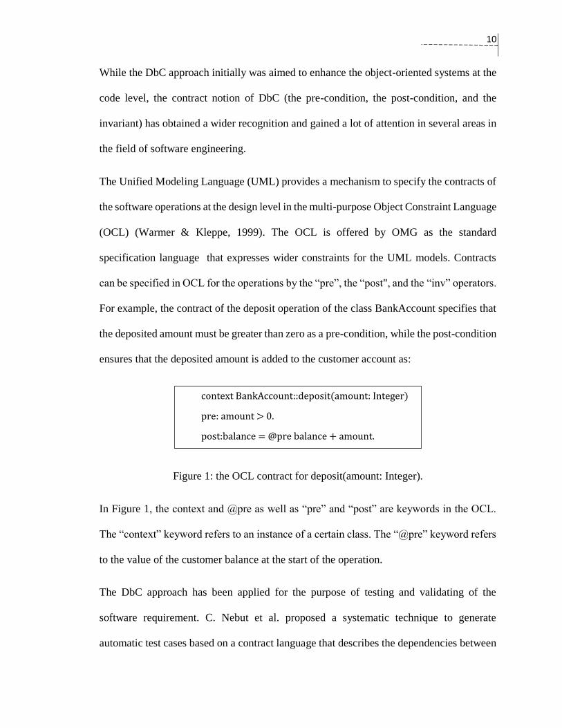
For example, the contract of the deposit operation of the class BankAccount specifies that
the deposited amount must be greater than zero as a pre-condition, while the post-condition
ensures that the deposited amount is added to the customer account as:
Figure 1: the OCL contract for deposit(amount: Integer).
In Figure 1, the context and @pre as well as “pre” and “post” are keywords in the OCL.
The “context” keyword refers to an instance of a certain class. The “@pre” keyword refers
to the value of the customer balance at the start of the operation.
The DbC approach has been applied for the purpose of testing and validating of the
software requirement. C. Nebut et al. proposed a systematic technique to generate
automatic test cases based on a contract language that describes the dependencies between
context BankAccount::deposit(amount: Integer)
pre: amount > 0.
post:balance = @pre balance + amount.

11
the use-cases (Nebut, Fleurey, Traon, & Jézéquel, 2003). The use-cases’ contracts are
parameterized, and form logical expressions in pre- and post-condition format. These
contracts can be used to determine the valid sequences of the use cases’ invocation. They
help to construct a transition system on which different coverage criteria can be applied for
the generation of tests. On the other side, the Another Contract Language (ACL) uses
contracts to validate the requirements (Arnold, Corriveau, & Shi, 2010). ACL forms a
Testable Requirements Model (TRM) that can be directly applied on running code. The
contracts of ACL validate the structural and behavioral constraints of the running
implementation of the software system. They describe the domain objects in terms of
observabilities, responsibilities, and scenarios. An observability is a query about a certain
data in an object. A responsibility represents a task of a certain object. A scenario comprises
several responsibilities. The example in Figure 2 describes a container behavior as
described in ACL.

12
Figure 2: ACL for Container requirements (Arnold et al., 2010).
In summary, the idea of C. A. R Hoare that improves the correctness of a computer program
via pre- and post-condition helped Meyer to propose the DbC approach. In turn, DbC has
inspired many software researchers to use the contract idea in several areas of software
engineering such as requirement engineering, software design, software testing, and
software model transformation.
2.2 Larman’ Operation Contracts
The DbC idea has inspired Craig Larman to propose the operation contracts as a technique
to specify the behavior of the system operations in a pre- and a post-condition form
(Larman, 2005, chapter 11). The operation contracts are requirement analysis artifacts.
They aim to bridge the gap between the requirement and the design in the development life
13
cycle. Precisely, they show a relation between the actors’ input and the system reaction in
the level of the domain objects. The operation contracts’ focus is to point out the required
modifications in the state of the domain objects without getting into details of how things
happened.
Larman introduced operation contracts as a first step to handle a complex task in designing
object-oriented systems, which is assigning objects’ responsibilities and managing their
interactions. Operation contracts help to identify the responsibilities of domain objects
based on system operations, which are deduced from the use-cases text. After identifying
the responsibilities, Larman identified some design guidance that they can be used to assign
the responsibilities to the involved domain objects, and then, to generate the interaction
diagrams.
Larman’s operation contracts are not new idea in the software engineering literature. They
has been used in several approaches: mainly as an input to automate the production of
design artifacts such as sequence diagrams (Bousetta, Omar, & Gadi, 2013; Shakya, B &
Nantajeewarawat, E. 2013; Laosen & Nantajeewarawat, 2015; Lohmann, Sauer, & Engels,
2005). Operation contracts attract numerous researchers because they tackle the possibility
of designing object interactions based on systematic approaches.
2.3 Visual Modeling
The visual modeling of software systems plays a major role in several software engineering
practices and has a great impact in software development processes. The software visual
models can state the requirements of the software system, communicate with software
14
developers and software end users, describe software components, and specify software
design and its behavior.
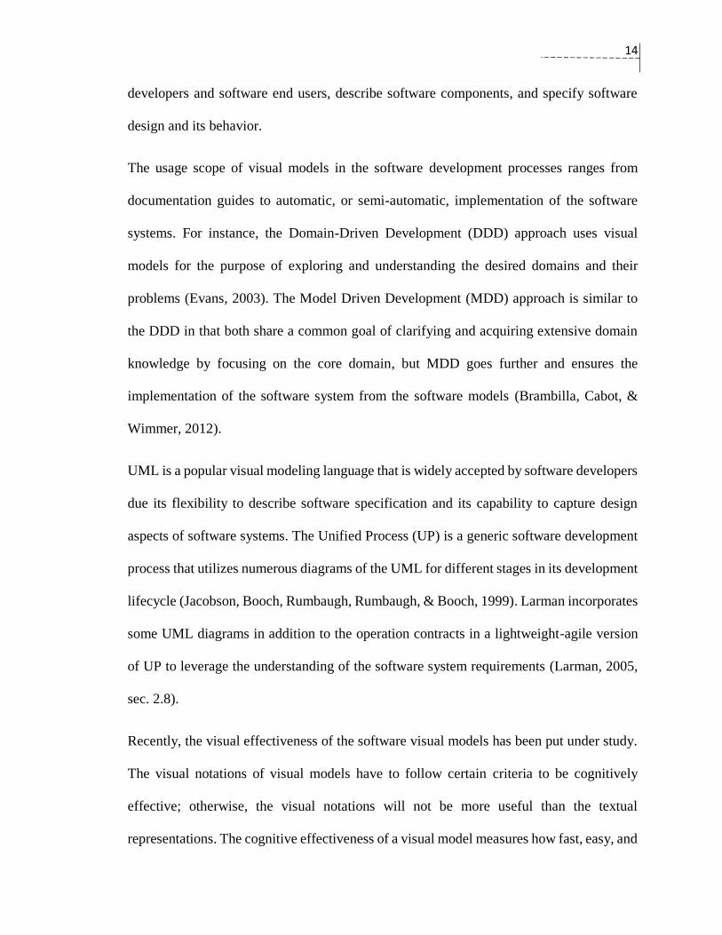
The usage scope of visual models in the software development processes ranges from
documentation guides to automatic, or semi-automatic, implementation of the software
systems. For instance, the Domain-Driven Development (DDD) approach uses visual
models for the purpose of exploring and understanding the desired domains and their
problems (Evans, 2003). The Model Driven Development (MDD) approach is similar to
the DDD in that both share a common goal of clarifying and acquiring extensive domain
knowledge by focusing on the core domain, but MDD goes further and ensures the
implementation of the software system from the software models (Brambilla, Cabot, &
Wimmer, 2012).
UML is a popular visual modeling language that is widely accepted by software developers
due its flexibility to describe software specification and its capability to capture design
aspects of software systems. The Unified Process (UP) is a generic software development
process that utilizes numerous diagrams of the UML for different stages in its development
lifecycle (Jacobson, Booch, Rumbaugh, Rumbaugh, & Booch, 1999). Larman incorporates
some UML diagrams in addition to the operation contracts in a lightweight-agile version
of UP to leverage the understanding of the software system requirements (Larman, 2005,
sec. 2.8).
Recently, the visual effectiveness of the software visual models has been put under study.
The visual notations of visual models have to follow certain criteria to be cognitively
effective; otherwise, the visual notations will not be more useful than the textual
representations. The cognitive effectiveness of a visual model measures how fast, easy, and
15
accurate the visual syntax is able to convey the required information (Larkin & Simon,
1987). The form of representations, the visual syntax, and what the visual syntax
represents, the semantics, are both influencing the cognitive effectiveness, and sometimes
the former has higher influence (Larkin & Simon, 1987). In fact, the visual models might
not be “worth a thousand words” unless their visual effectiveness is taken into
consideration (Cheng, Lowe, & Scaife, 2001).
While there are several approaches to evaluate the effectiveness of the visual notations in
the software visual models; the Physics of Notation theory seems the most appropriate one
in this field (Moody, 2009). It has been used to validate several models like UML (Moody
& Hillegersberg, 2009), i*(Moody, Heymans, & Matulevičius, 2010), and UCM (Genon,
Amyot, & Heymans, 2011).We will use the physics of notation theory as the evaluation
criteria for the effectiveness of our visual operation contract in section 5.6.
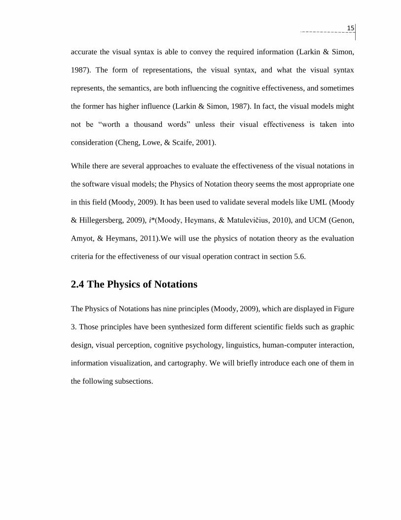
2.4 The Physics of Notations
The Physics of Notations has nine principles (Moody, 2009), which are displayed in Figure
3. Those principles have been synthesized form different scientific fields such as graphic
design, visual perception, cognitive psychology, linguistics, human-computer interaction,
information visualization, and cartography. We will briefly introduce each one of them in
the following subsections.
16
Figure 3: The nine principles of the physics of notations theory (Moody, 2009).
2.4.1 Semiotic Clarity
The semiotic clarity principle limits the usage of each single graphical symbol to only one
semantic construct. Violation of this principle leads to negative consequences and reduces
the effectiveness of the graphical model. The following four parameters are provided to
assess the semiotic clarity:
Symbol Deficit: when a semantic does not have a representation.
Symbol Overload: when multiple semantic constructs maps to one symbol.
Symbol Excess: when a visual symbol does not reflect any semantic construct.
Symbol Redundancy: when one semantic construct is represented by multiple
symbols.
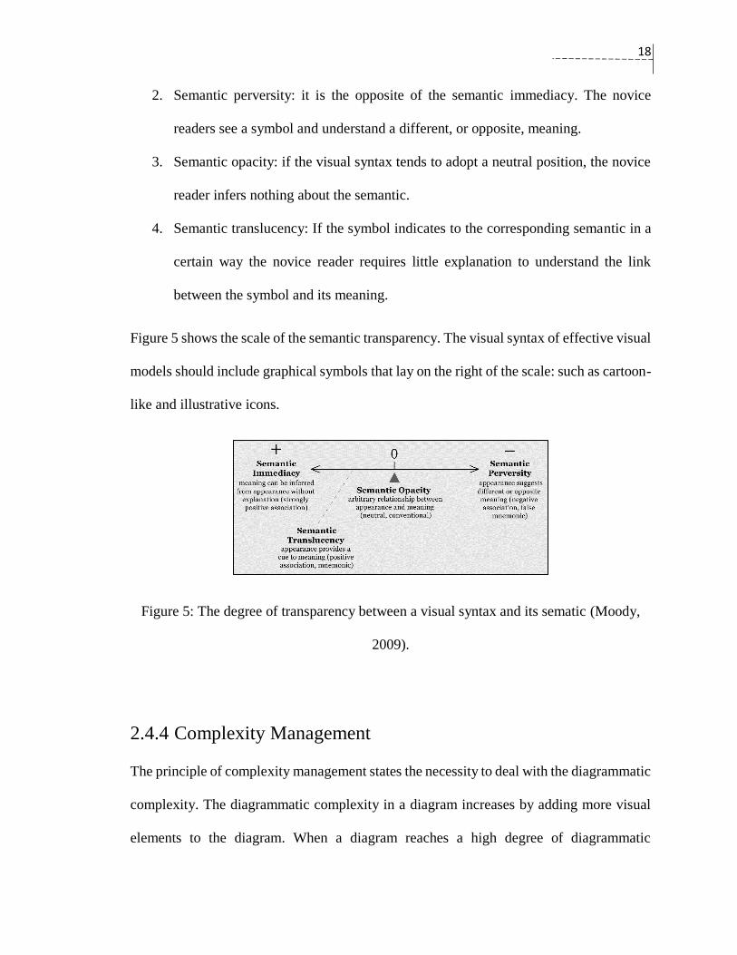
2.4.2 Perceptual Discriminability
The perceptual discriminability principle measures how easy and accurate it is for the
human mind to differentiate between the two symbols in the visual diagram. The perceptual
discriminability can be identified by the visual distance. The visual distance can be

17
determined by the number of the visual variables (Figure 4) that are used to differentiate a
symbol from another and the size of the difference. The size of the difference can be
determined by the number of the perceptible steps that the human mind takes to
discriminate one symbol form the other (Purchase, Carrington, & Allder, 2002). The field
of psychophysics can provide some guidance on the matter of the perceptible steps. The
general rule of the Physics of Notation is not to use one visual variable such as the text;
but, instead, to use more combinations of the visual variables to obtain a high visual
distance.
Figure 4: The visual variables that affect the visual distance (Moody, 2009).
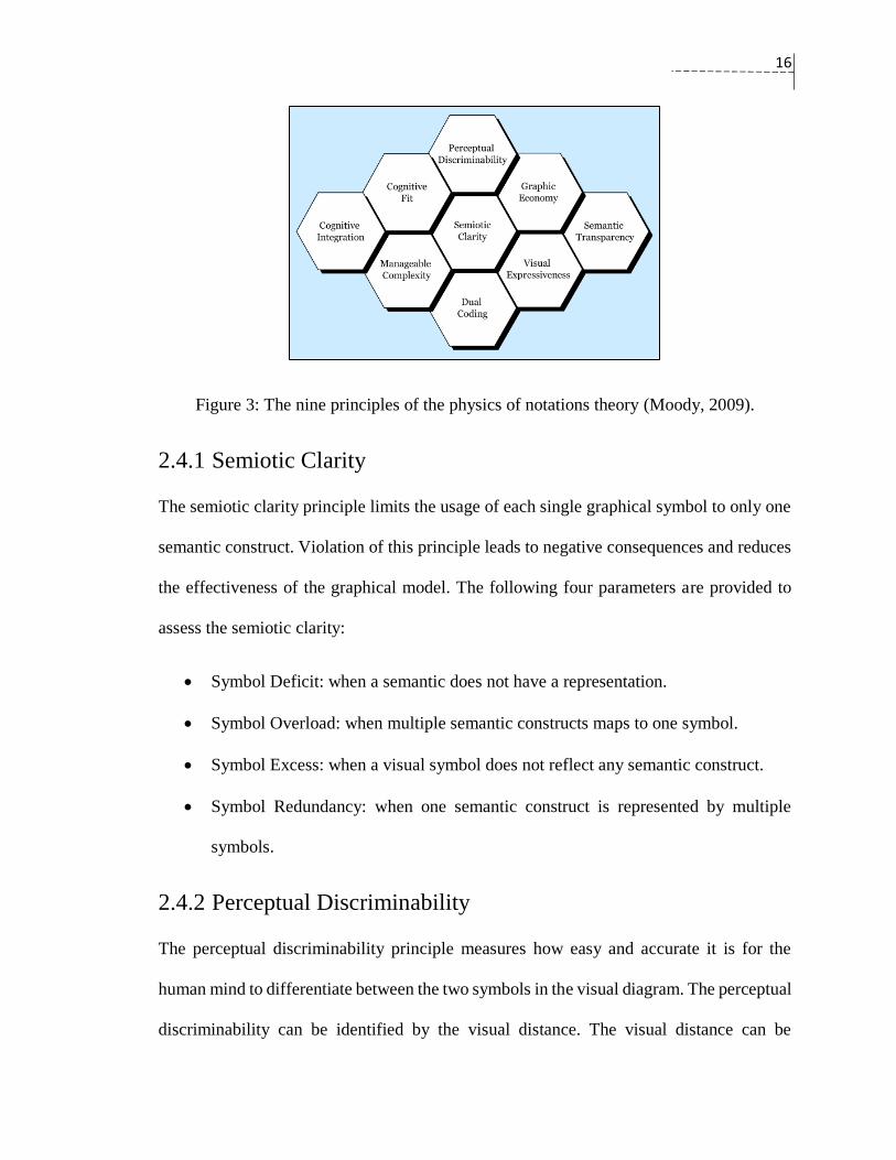
2.4.3 Semantic Transparency
The semantic transparency principle advocates using graphical symbols that have clear
indications to their semantic counterparts. The degrees of the transparency between the
visual syntax and the semantic can be categorized into the following four points:
1. Semantic immediacy: If the novice readers can directly understand the semantic of
the symbols by looking at it without any interference and explanation.
18
2. Semantic perversity: it is the opposite of the semantic immediacy. The novice
readers see a symbol and understand a different, or opposite, meaning.
3. Semantic opacity: if the visual syntax tends to adopt a neutral position, the novice
reader infers nothing about the semantic.
4. Semantic translucency: If the symbol indicates to the corresponding semantic in a
certain way the novice reader requires little explanation to understand the link
between the symbol and its meaning.
Figure 5 shows the scale of the semantic transparency. The visual syntax of effective visual
models should include graphical symbols that lay on the right of the scale: such as cartoon-
like and illustrative icons.
Figure 5: The degree of transparency between a visual syntax and its sematic (Moody,
2009).
2.4.4 Complexity Management
The principle of complexity management states the necessity to deal with the diagrammatic
complexity. The diagrammatic complexity in a diagram increases by adding more visual
elements to the diagram. When a diagram reaches a high degree of diagrammatic
19
complexity, the discriminability of its symbols and the comprehension of the whole
diagram will decrease. The Physics of Notation provides two mechanisms to reduce the
diagrammatic complexity. The first one is called the modularization mechanism, which is
decomposing the diagram into smaller subsystems. The second mechanism is grouping the
visual elements to abstraction levels, or hierarchies.
2.4.5 Cognitive Integration
The cognitive integration principle sets integration mechanisms that are applicable for
diagrams that describe a single system from different perspectives. There are two parts of
the cognitive integration: the conceptual integration and the perceptual integration. The
conceptual integration offers mechanisms that enable the creation of a diagram that is
comprehensible, coherent, and representative for the involved diagrams. The perceptual
integration seeks mechanisms that help in the navigation and the transition between
diagrams.
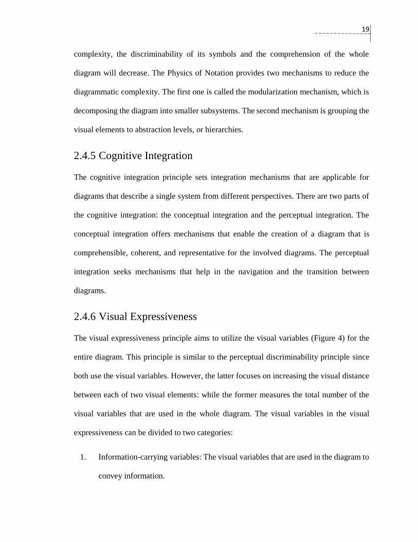
2.4.6 Visual Expressiveness
The visual expressiveness principle aims to utilize the visual variables (Figure 4) for the
entire diagram. This principle is similar to the perceptual discriminability principle since
both use the visual variables. However, the latter focuses on increasing the visual distance
between each of two visual elements: while the former measures the total number of the
visual variables that are used in the whole diagram. The visual variables in the visual
expressiveness can be divided to two categories:
1. Information-carrying variables: The visual variables that are used in the diagram to
convey information.

20
2. Free variables: The visual variables that are not used in the diagram.
The total number of the visual variables that are used in the diagram can calculate the visual
expressiveness as in Figure 6. The diagram will be visually saturated when the entire eight
visual variables are utilized to form the visual elements of a diagram.
Figure 6: The visual expressiveness depends on the total number of the visual variables
(Moody, 2009).
The visual expressiveness principle also puts some guidance on the selection of the visual
variables according to the information class. Table 1 shows the eight visual variables, their
power, and their capacities. The power column points to the suitable class of information
to which a visual variable can refer. The capacity column displays the range of the
perceptible steps that each visual variable can have.
21
Table 1: Each visual variable has specific capabilities for encoding the information
(Moody, 2009).
2.4.7 Dual Coding
The dual coding principle encourages using textual labels to leverage the discriminability
between the symbols. This principle is based on the dual coding theory. It states that the
addition of a text clarification to a graphical symbol elevates its effectiveness (Paivio,
1990). This principle places great emphasis on the benefits of augmenting the visual
representation of the symbols with texts that improve the perceptual discriminability.
2.4.8 Graphic Economy
The graphic economy principle provides some guidance and strategies to deal with the
graphic complexity. The graphic complexity can be defined as the basic number of the
visualized elements (legend) of a notation. In fact, the excessive addition of the symbols to
a diagram increases its semiotic transparency; but it also leads to a high increase in the
graphic complexity. The cognitive ability of the human mind, with no prior experience to
the notation, is limited to distinguishing between six categories of symbols (Miller, 1956).
Therefore, the graphic complexity of the visual notations should be around six.

22
There are three strategies to reduce the graphic complexity. First, it can be reduced by
minimizing the sematic constructs that are covered by the diagram. Second, the reduction
can occur if some symbols are removed from the diagram and are replaced by text
annotations. Hence, the semiotic clarity will decrease as there is high symbol deficits.
Third, the increasing the visual expressiveness of the diagram helps to the human main to
notice the differences between the symbols.
2.4.9 Cognitive Fit
The cognitive fit principle is based on the cognitive fit theory, which promotes the use of
different representations of the semantic to fit the diversity of the audiences and the task
characteristics (Shaft & Vessey, 2006). In the software engineering context, the users of
the visual diagrams can be divided into two types: the novices and the experts. The novices
often have less discriminability and have more difficulties in remembering the meanings
of the symbols. Therefore, the cognitive fit principle encourages using two dialects: “lite”
for the novices, and “pro” for the experts. The second part of the cognitive fit theory is the
adaptation for the task characteristics, which refers to the type of mediums on which that
the diagram will be drawn. The cognitive fit principle argues the need for one “sketching”
version, and one rich version for the drawing tools.

23
Chapter 3: Related Work
In this chapter, a literature review is provided for the Design by Contract-related
approaches targeting the requirement, or high-level design phases. These approaches
include: automatic generation of operation contracts, generation of behavioral diagrams
from operation contracts, and visualization of operation contracts.
3.1 Automatic Generation of Operation Contracts
J. Cabot and C. Gómez propose an approach to help in generating automatic OCL contracts
for the basic classes’ operations in the class diagram (Cabot & Gómez, 2007). Basic
operations include a “Create” operation and a “Delete” operation for each class, an
“Update” operation for each modifiable attribute, a “Generalize” operation for each sub-
class, a “Specialize” operation for each superclass, as well as two “Create” and “Delete”
operations for each association in the participating classes. Figure 8 shows the operations
that were added to the original class diagram presented in Figure 7.
24
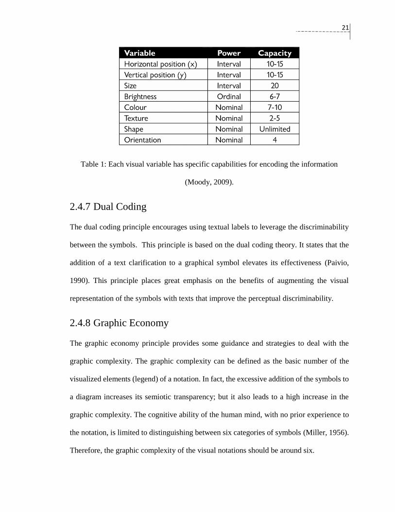
Figure 7: The original class diagram (Cabot & Gómez, 2007)
Figure 8: The class diagram after addition of the basic operations (Cabot & Gómez, 2007)
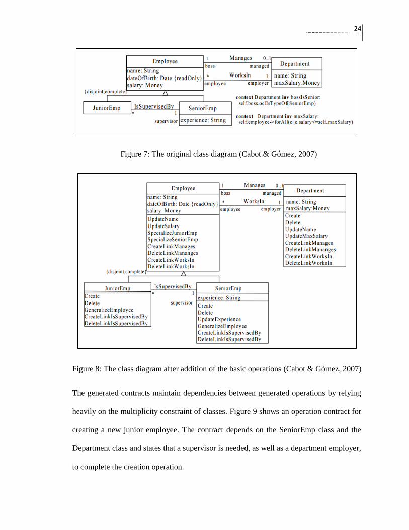
The generated contracts maintain dependencies between generated operations by relying
heavily on the multiplicity constraint of classes. Figure 9 shows an operation contract for
creating a new junior employee. The contract depends on the SeniorEmp class and the
Department class and states that a supervisor is needed, as well as a department employer,
to complete the creation operation.
25
Figure 9: The OCL contract for the creation operation of the class JuniorEmp (Cabot &
Gómez, 2007)
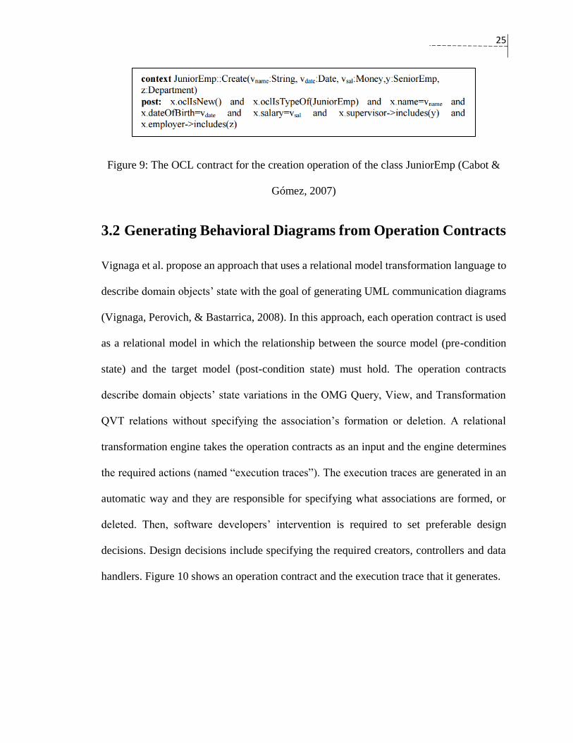
3.2 Generating Behavioral Diagrams from Operation Contracts
Vignaga et al. propose an approach that uses a relational model transformation language to
describe domain objects’ state with the goal of generating UML communication diagrams
(Vignaga, Perovich, & Bastarrica, 2008). In this approach, each operation contract is used
as a relational model in which the relationship between the source model (pre-condition
state) and the target model (post-condition state) must hold. The operation contracts
describe domain objects’ state variations in the OMG Query, View, and Transformation
QVT relations without specifying the association’s formation or deletion. A relational
transformation engine takes the operation contracts as an input and the engine determines
the required actions (named “execution traces”). The execution traces are generated in an
automatic way and they are responsible for specifying what associations are formed, or
deleted. Then, software developers’ intervention is required to set preferable design
decisions. Design decisions include specifying the required creators, controllers and data
handlers. Figure 10 shows an operation contract and the execution trace that it generates.

26
Figure 10: On the left figure, an operation contract, and on the right figure, the execution
trace that has design choices (manually added to the execution trace in line 14-16) (Vignaga
et al., 2008).
B. Bousetta et al. propose a model-driven approach that aims to semi-automate the
generation of system sequence diagrams (Bousetta, Omar, & Gadi, 2013). It uses the
extended syntax of Larman’s operation contracts to form an object design that respects the
model-view-controller (MVC) pattern. Their proposal focuses on the syntax of Larman’s
operation post-condition, and extends this to accommodate more details that specify the
way in which domain objects are invoked, such as which object is responsible for executing
the operation and who originates, or creates, its involved domain objects. The extensions
are necessary for generating sequence diagrams based on operation contracts because the
27
syntax of Larman’s contracts cannot solely achieve this goal. The detailed syntax of the
post-condition explicitly imbeds hints about the GRASP patterns and introduces new
keywords like “check”,” display” and “print”. For example, when Larman uses “ClassA
instance objectA was created” as a post-condition sentence, the extended post-condition
sentence in this approach adds “created by Responsible ClassB” to the previous sentence,
which becomes “ClassA instance objectA was created by Responsible ClassB”, where
ClassA and ClassB are two classes, and objectA (lowercase) refers to an instance of class
ClassA.
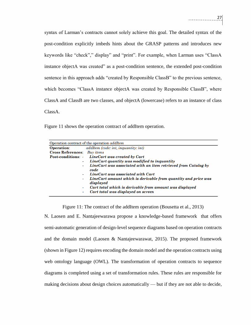
Figure 11 shows the operation contract of addItem operation.
Figure 11: The contract of the addItem operation (Bousetta et al., 2013)
N. Laosen and E. Nantajeewarawa propose a knowledge-based framework that offers
semi-automatic generation of design-level sequence diagrams based on operation contracts
and the domain model (Laosen & Nantajeewarawat, 2015). The proposed framework
(shown in Figure 12) requires encoding the domain model and the operation contracts using
web ontology language (OWL). The transformation of operation contracts to sequence
diagrams is completed using a set of transformation rules. These rules are responsible for
making decisions about design choices automatically — but if they are not able to decide,

28
the task will be delegated to software developers. The transformation rules are derived from
the general syntax of Larman’s operation contracts and three GRAPS patterns: the creator,
the information expert and the controller patterns. The handling rules and the supporting
rules are the two main categories of the transformation rules. The handling rules translate
formation of associations, modification of attributes, compositions, and creation of objects
of the post-condition into specific elements in sequence diagrams. The supporting rules act
as helpers for the post-condition rules and assist in realizing them.
Figure 12: An overview of the proposed knowledge-based framework (Laosen &
Nantajeewarawat, 2015)
3.3 Visualization of Operation Contracts
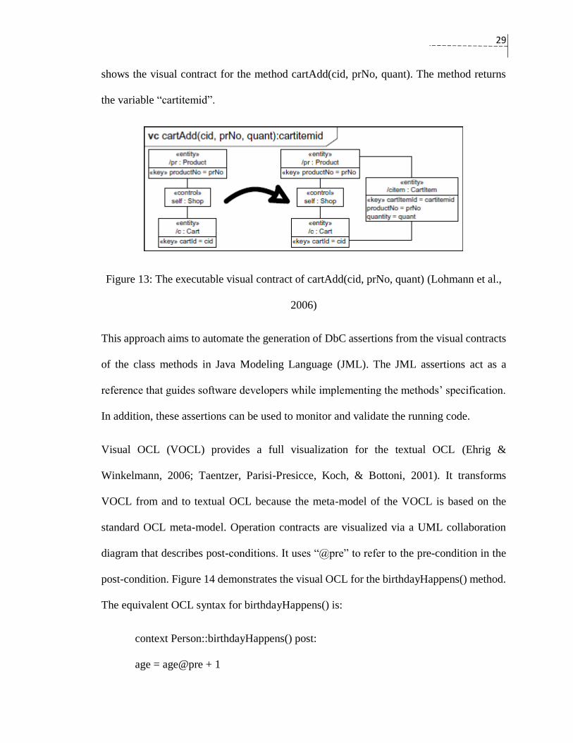
Lohmann et al. proposed a visual notation (the executable visual contract) to specify
changes attributes’ states, and associations in a class operation (Heckel & Lohmann, 2007;
Lohmann, Engels, & Sauer, 2006; Lohmann, Sauer, & Engels, 2005). An executable visual
contract consists of one diagram that encloses two separate UML object diagrams. The
object diagrams capture the pre-conditions and post-conditions of an operation. Figure 13
29
shows the visual contract for the method cartAdd(cid, prNo, quant). The method returns
the variable “cartitemid”.
Figure 13: The executable visual contract of cartAdd(cid, prNo, quant) (Lohmann et al.,
2006)
This approach aims to automate the generation of DbC assertions from the visual contracts
of the class methods in Java Modeling Language (JML). The JML assertions act as a
reference that guides software developers while implementing the methods’ specification.
In addition, these assertions can be used to monitor and validate the running code.
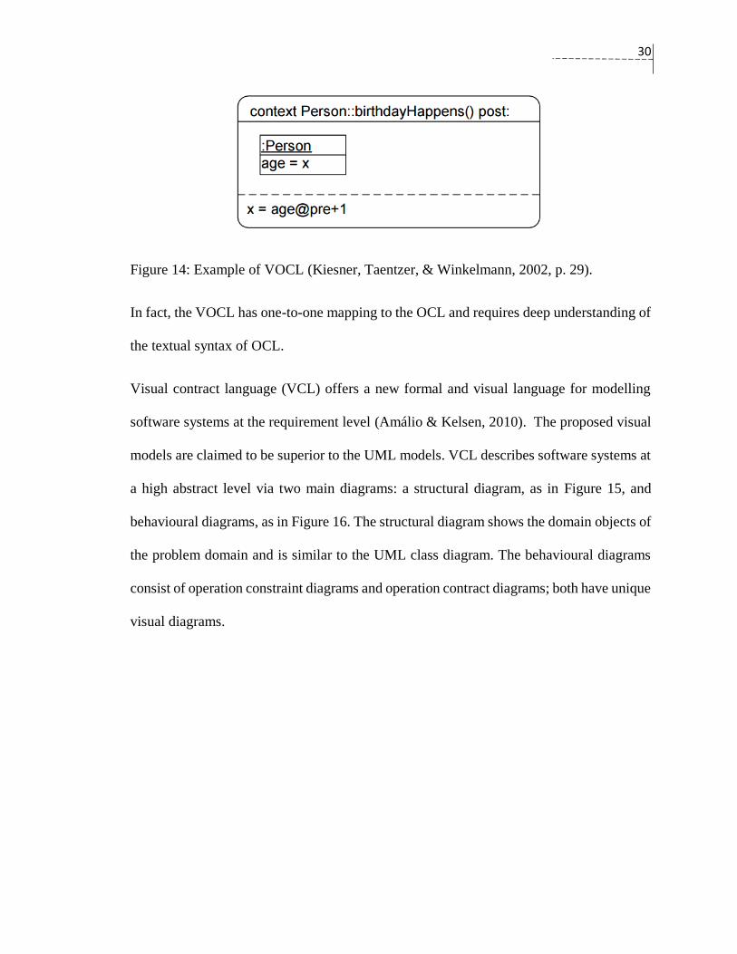
Visual OCL (VOCL) provides a full visualization for the textual OCL (Ehrig &
Winkelmann, 2006; Taentzer, Parisi-Presicce, Koch, & Bottoni, 2001). It transforms
VOCL from and to textual OCL because the meta-model of the VOCL is based on the
standard OCL meta-model. Operation contracts are visualized via a UML collaboration
diagram that describes post-conditions. It uses “@pre” to refer to the pre-condition in the
post-condition. Figure 14 demonstrates the visual OCL for the birthdayHappens() method.
The equivalent OCL syntax for birthdayHappens() is:
context Person::birthdayHappens() post:
age = age@pre + 1
30
Figure 14: Example of VOCL (Kiesner, Taentzer, & Winkelmann, 2002, p. 29).
In fact, the VOCL has one-to-one mapping to the OCL and requires deep understanding of
the textual syntax of OCL.
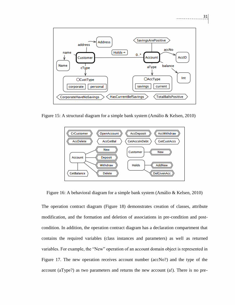
Visual contract language (VCL) offers a new formal and visual language for modelling
software systems at the requirement level (Amálio & Kelsen, 2010). The proposed visual
models are claimed to be superior to the UML models. VCL describes software systems at
a high abstract level via two main diagrams: a structural diagram, as in Figure 15, and
behavioural diagrams, as in Figure 16. The structural diagram shows the domain objects of
the problem domain and is similar to the UML class diagram. The behavioural diagrams
consist of operation constraint diagrams and operation contract diagrams; both have unique
visual diagrams.
31
Figure 15: A structural diagram for a simple bank system (Amálio & Kelsen, 2010)
Figure 16: A behavioral diagram for a simple bank system (Amálio & Kelsen, 2010)
The operation contract diagram (Figure 18) demonstrates creation of classes, attribute
modification, and the formation and deletion of associations in pre-condition and post-
condition. In addition, the operation contract diagram has a declaration compartment that
contains the required variables (class instances and parameters) as well as returned
variables. For example, the “New” operation of an account domain object is represented in
Figure 17. The new operation receives account number (accNo?) and the type of the
account (aType?) as two parameters and returns the new account (a!). There is no pre-

32
condition for this operation, while the post-condition shows that the new account (a!) will
have the values (acc?, 0, and aType?) for its properties: accNo, balance, and aType.
Figure 17: The contract diagrams for the new operation of the account domain object, and
the delete operation (Amálio & Kelsen, 2010)
The visual models in the VCL can be transformed to formal specifications written in the
formal Z language. The major drawback of this is that software engineers are often
reluctant to learn another modelling language, which has new notations and various
diagrams.
33
Chapter 4: Operation Contracts
This chapter discusses Larman’s operation contracts in details. The chapter starts by
showing the link between operation contracts, system operations, and the domain model.
Then, the chapter presents the textual template of the operation contracts, and offers
illustrative examples of how it can be used to analyze a system operation. Finally, this
chapter discusses some limitations in the operation contracts.
4.1 Software Operations
According to Craig Larman, a software system can be seen as a black box interacting with
external actors through system events (Larman, 2005, sec. 10.2). This type of interaction
usually is initiated by a request from a particular actor in the software system. The system
operations are a public interface to the software system and they handle system events. The
specifications of a system operation highlights what the software system should do without
specifying the implementation details (Lethbridge & Laganiere, 2001, p. 38). The system
events and the system operations help us to draw a picture about the general behavior of
the software system and how the system interacts with external components.
System’s operation can be derived from the use-cases’ text, and they are often invoked in
a specific manner. The order in which system operations are invoked in a use-case scenario
can be specified via a system sequence diagram. Each message in a system sequence
diagram represents a system event since it originates from an external actor. It also
represents a system operation because it abstracts the required actions that the software

34
system must perform. The collection of the system sequence diagrams are very illustrative;
and they build a common understanding of the software functionalities between the
software provider and its stakeholders.
The relationship between use-case diagram, the domain model, system sequence diagram,
and system operations will be illustrated by an example in the next section.
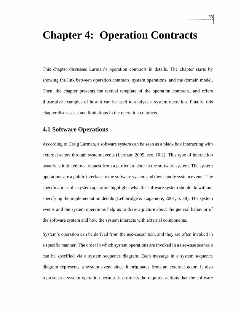
4.1.1 Auction System Example
We use an online auction system (AuctionSystem) to illustrate the relationship between the
use-case diagram, sequence diagram, and system operations (Eeles, Houston, &
Kozaczynski, 2002, p. 61). The AuctionSystem is a software system that manages online-
auction deals between buyers and sellers. It allows sellers to offer items for bidding for a
certain period of time. The bidding should close at the end of the duration and the highest
bid should be selected upon the closing. Buyers are allowed to make bids for an opened
auction, if their payment information is available prior to make the bid. The use-case
diagram of the auction system in Figure 18 shows different actors, use-cases, and
association links. The direction of the association arrow between an actor and a use-case
indicates which one begins the scenario in a source-target style. For instance, Close
Auction will begin the scenario at the end of the bid duration by notifying the seller, the
buyer, and the credit service bureau to take out the money from the seller.
35
Figure 18 : Use Case Diagram for AuctionSystem (Eeles et al., 2002, p. 93).
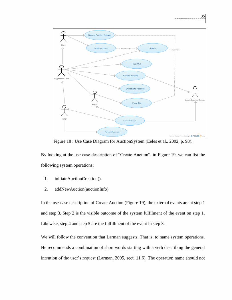
By looking at the use-case description of “Create Auction”, in Figure 19, we can list the
following system operations:
1. initiateAuctionCreation().
2. addNewAuction(auctionInfo).
In the use-case description of Create Auction (Figure 19), the external events are at step 1
and step 3. Step 2 is the visible outcome of the system fulfilment of the event on step 1.
Likewise, step 4 and step 5 are the fulfillment of the event in step 3.
We will follow the convention that Larman suggests. That is, to name system operations.
He recommends a combination of short words starting with a verb describing the general
intention of the user’s request (Larman, 2005, sect. 11.6). The operation name should not
36
be tied to a technology or a design choice; instead, it should be abstract and like “make…”,
“enter…” and so on.
Figure 19: The description of Create Auction use-case.
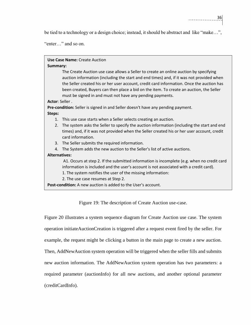
Figure 20 illustrates a system sequence diagram for Create Auction use case. The system
operation initiateAuctionCreation is triggered after a request event fired by the seller. For
example, the request might be clicking a button in the main page to create a new auction.
Then, AddNewAuction system operation will be triggered when the seller fills and submits
new auction information. The AddNewAuction system operation has two parameters: a
required parameter (auctionInfo) for all new auctions, and another optional parameter
(creditCardInfo).
Use Case Name: Create Auction
Summary:
The Create Auction use case allows a Seller to create an online auction by specifying
auction information (including the start and end times) and, if it was not provided when
the Seller created his or her user account, credit card information. Once the auction has
been created, Buyers can then place a bid on the item. To create an auction, the Seller
must be signed in and must not have any pending payments.
Actor: Seller .
Pre-condition: Seller is signed in and Seller doesn't have any pending payment.
Steps:
1. This use case starts when a Seller selects creating an auction.
2. The system asks the Seller to specify the auction information (including the start and end
times) and, if it was not provided when the Seller created his or her user account, credit
card information.
3. The Seller submits the required information.
4. The System adds the new auction to the Seller's list of active auctions.
Alternatives:
A1. Occurs at step 2. If the submitted information is incomplete (e.g. when no credit card
information is included and the user's account is not associated with a credit card).
1. The system notifies the user of the missing information:
2. The use case resumes at Step 2.
Post-condition: A new auction is added to the User's account.
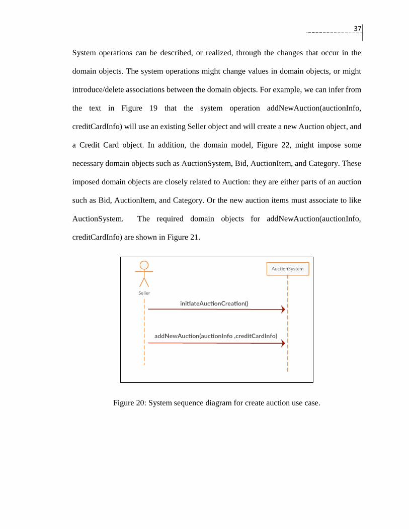
37
System operations can be described, or realized, through the changes that occur in the
domain objects. The system operations might change values in domain objects, or might
introduce/delete associations between the domain objects. For example, we can infer from
the text in Figure 19 that the system operation addNewAuction(auctionInfo,
creditCardInfo) will use an existing Seller object and will create a new Auction object, and
a Credit Card object. In addition, the domain model, Figure 22, might impose some
necessary domain objects such as AuctionSystem, Bid, AuctionItem, and Category. These
imposed domain objects are closely related to Auction: they are either parts of an auction
such as Bid, AuctionItem, and Category. Or the new auction items must associate to like
AuctionSystem. The required domain objects for addNewAuction(auctionInfo,
creditCardInfo) are shown in Figure 21.
Figure 20: System sequence diagram for create auction use case.

38
Figure 21: The required domain entities of the domain model to realize
addNewAuction(auctionInfo, creditCardInfo).
A use-case realization is the mapping of a particular use-case to its design via the
collaborating objects (Kruchten, 2000). The realization of use-cases occurs in three levels
of details (ordered form high to low): implementation level, responsibility level, and
interaction level (Jacobson, Spence, & Bittner, 2011). The interaction level is very abstract
and helps to handle complex and challenging systems. It can also assist software developers
who do not acquire solid skills in software design.
Larman shows that the operation contracts are a powerful tool to obtain an effective design
of the software systems. The operation contracts describe behavioral aspects of the system

39
operations in a declarative way, and they avoid implementation-specific details. The main
issue of declarative specifications is the underspecification, which is the possibility of
obtaining several ways of implementation (Wieringa, 1998). For this matter and in the
design phase, the operation contracts can serve to construct interaction diagrams by the
help of GRASP patterns. The GRASP patterns include nine design patterns: Creator,
Controller, Pure Fabrication, Information Expert, High Cohesion, Indirection, Low
Coupling, Polymorphism, and Protected Variations. The GRASP patterns require three
software requirement artifacts: domain model, use-cases’ description and operation
contracts.

40
Figure 22: Domain model for the AuctionSystem.
4.2 System Operation Contracts
Larman introduced the notion of contract to describe the complex system operations in
software systems. He considered them as a part of the requirements as in Figure 23. The
aim of the operation contracts is to capture the state of the software system before and after
performing an operation in a pre-condition and a post-condition format (Larman, 2005,
chapter 11). The operation contracts use natural language description that breaks complex
system operations into simple segments to describe changes of the software system in terms
of domain objects. The changes in the domain objects are defined according to the
following categories:
1. Creation of domain instances;
2. Deletion of domain instances;
3. Change of attribute values;
4. Creation of associations; and
5. Deletion of associations.

41
Figure 23: Operation contract in use-case model (Larman, 2005).
4.2.1 Larman Template for Operation Contracts
Larman uses a template that consists of four main sections as Figure 24 shows. The sections
are the following: operation, cross Reference, pre-condition, and post-condition. Larman
suggested writing post-condition in the past tense form such as “ClassA was associated

42
with ClassB” to indicate that the action had already happened after executing the operation.
The syntax of Larman’s operation contracts is presented in Table 2.
Figure 24: Larman operation contract (Larman, 2005).
Type Syntax of the post-condition
Instance creation A <ClassName> instance <instanceName> was created.
Instance deletion <instanceName> was deleted .
Change of attribute <instanceName>.<attributeName> became
<instanceName2>.<attriuteName> | Boolean | “string value”.
Formation of
association
<instanceName1> was associated with <instanceName2>
<instanceName1> was associated with <instanceName2> based on
<instanceName2>.<attribute1>
deletion of association <instanceName1> was disassociated from <instanceName2>
Table 2: Syntax of Larman’s operation contracts.
We applied the Larman contract on the create auction use-case. The system sequence
diagram in Figure 20 and the domain model diagram in Figure 22 are the sources for the
operation contracts. The outcome is the following two operation contracts:
Operation: initiateAuctionCreation()
Cross References: Use-case: Create Auction

43
Pre-conditions: there is an existing instance of UserAccount useracc
Post-conditions:
Table 3: Operation contract for initiateAuctionCreation.
Operation: addNewAuction(auctionInfo)
Cross References: Use-case: Create Auction
Pre-conditions: there is an existing instance of AuctionSystem aucsyst
seller is a non null instance of useracc
seller.pending Payment is empty
If seller.credit card is null, auctionInfo includes credit card infos
Post-conditions:
a new instance of Auction auc was created (instance creation)
the attributes of auc were initialized from auctionInfo (attribute
modification)
auc was associated with aucsyst (association creation)
auc was associated with seller (association creation)
auc was associated with an instance of Category cat based on a
category name from auctionInfo (association creation)
an instance of Auction Item aucIt was created
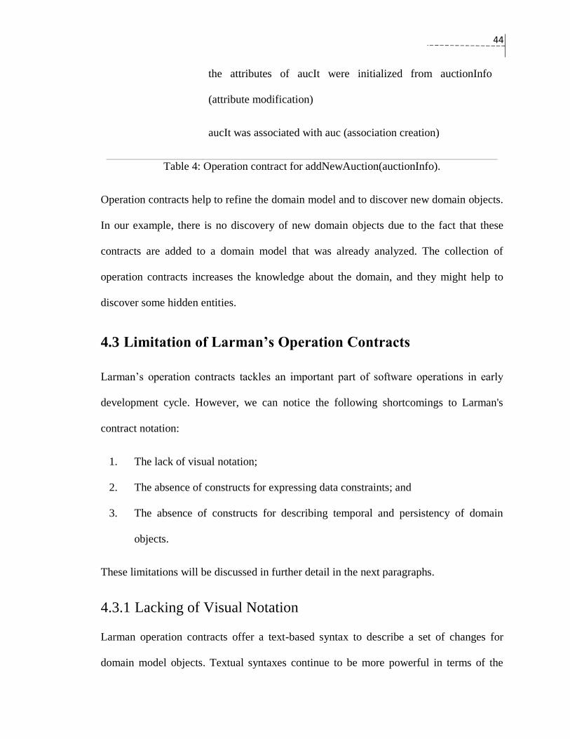
44
the attributes of aucIt were initialized from auctionInfo
(attribute modification)
aucIt was associated with auc (association creation)
Table 4: Operation contract for addNewAuction(auctionInfo).
Operation contracts help to refine the domain model and to discover new domain objects.
In our example, there is no discovery of new domain objects due to the fact that these
contracts are added to a domain model that was already analyzed. The collection of
operation contracts increases the knowledge about the domain, and they might help to
discover some hidden entities.
4.3 Limitation of Larman’s Operation Contracts
Larman’s operation contracts tackles an important part of software operations in early
development cycle. However, we can notice the following shortcomings to Larman's
contract notation:
1. The lack of visual notation;
2. The absence of constructs for expressing data constraints; and
3. The absence of constructs for describing temporal and persistency of domain
objects.
These limitations will be discussed in further detail in the next paragraphs.
4.3.1 Lacking of Visual Notation
Larman operation contracts offer a text-based syntax to describe a set of changes for
domain model objects. Textual syntaxes continue to be more powerful in terms of the

45
reduction of cognitive effort, the flexibility to change, and its reusability (Abdelzad et al.,
2015). However, the description of changes that occur in software operations using textual
format can be improved by an effective visual alternative, since software engineers are
often fully exploiting visual models for understanding and analyzing the software
requirement.
It is also perfectly rational to use an effective visual representation of the text version of
Larman’s operation contracts, because effective visuals offer better comprehension and
high memory utilization of the human mind. The human mind comprehends visual
diagrams and written text in two different ways: it reads words in sequential steps, while it
absorbs information of visual diagrams in parallel process (Bertin, 1983). This parallel
process is believed to have implications in speeding up comprehension. Hence, readers
need less time to assimilate new ideas in a visual notation. In addition, information
presented in an effective diagram has more potential to stay longer in our mind because of
the picture superiority effect (Goolkasian, 2000). Therefore, visual notation superiority can
be utilized for streamlining the understanding process of software operation contracts.
4.3.2 The Lack of Constructs for Expressing Data Constraints
Larman operation contracts do not provide formal description for data constraints used in
the operation contracts. The description of a system operation might impose some
constraints on the operation parameters and the instance fields of the involved domain
objects. The modification statement in the contracts describe only what the new values are
going to be without specifying the valid ranges for those values. For example, a contract
of the software operation processWithdraw(amount) of a bank system, which has
BankAccount class, will consider the following update statement in its post-condition:

46
“BankAccount.balance became balance – amount”. This operation contract misses a clear
constraint about the parameter “amount”; the withdrawn money should be greater than zero
and less than or equal to the balance of the bank customer.
In fact, the clarification of the data constraints in the operation contracts, such as the
numerical boundaries and the valid types of the data of the parameters and the instance
fields of an object, is not addressed in Larman’s template. The expressing of data
constraints in the operation contracts elevates their usage scope, especially for software
systems that adopt DbC in design and implementation.
4.3.3 The Lack of Constructs for Describing Temporal and
Persistency Aspects of Domain Objects
The operation contracts do not offer a specific way to identify whether the domain objects
have permanent or transient nature for their data in the creation statement. Moreover,
domain objects might be created based on stored data. The create statement of Larman’s
operation contracts describes only the domain objects that add new data to the domain. In
fact, the create statement is not appropriate to be used to describe domain objects that are
retrieved from the stored data, or are created temporarily and they neither retrieve nor store
any data.
Let us take an example that clarifies these aspects. Suppose there is a ShapeSystem that
has a draw(pointx, pointy) operation. It draws a line between the two entered points using
an instance of a Line class. For simplicity, suppose there is a single screen through which
user input is captured. The specification of the operation draw(pointx, pointy) might vary
as the following:

47
Case1: The specification of draw(pointx, pointy) states that it should draw a line connecting
the two points without saving the Line instance data. The Line object is a temporary object
that has no effect on the stored data.
Case2: The specification of draw(pointx, pointy) states that it should draw a line connecting
the two points. All instances of the Line class should be saved as persistent data after
performing the operation. In this case, the data of every new object is saved.
Case3: The specification of draw(pointx, pointy) states that it should draw a line connecting
the two points only if the points of the line have not been entered before. The new instances
of the Line object should be saved as persistent data. Therefore, the Line object might affect
the saved data.
Case4: The specification of draw(pointx, pointy) states that it should draw a line connecting
the two points. If the Line points are not new to the system, the Line object has an
“occurrence” attribute that should increment by one. Otherwise, the new instance of the
Line object should be saved as new data. Therefore, the saved data will always change after
performing the draw operation.
The first operation contract in Table 5 describes the post-conditions of Case1 and Case2.
While the two cases have an identical behavior, the Case2 specification states the need to
store the new data. Because there is no formal way in Larman’s operation contract notation
to differentiate between the two cases, the post-condition of Case1 should include a line at
the end of the operation contract like “ln was not saved as a new data”.
Operation: draw1(pointx, pointy)

48
Cross References: Use case: Draw
Pre-conditions: None
Post-conditions: A new instance of Line ln was created
ln.x became pointx
ln.y became pointy
Table 5: draw1(pointx, pointy) operation contract.
The second version draw2(pointx,pointy) in Table 6 describes the post-conditions of
Case3. The post-condition of the operation contract shows the need for a formal way to
retrieve stored data. It shows, also, the need for applying some sort of data checking by
using the “if” operator. We use the sentence in the first line of the post-condition “If pointx
and pointy have not been entered before”, since Larman operation contracts do not provide
a formal syntax to express these operations.
Operation: draw2(pointx, pointy)
Cross References: Use case: Draw
Pre-conditions: None
Post-conditions: If pointx and pointy has not been entered before:
A new instance of Line ln was created:
ln.x became pointx
ln.y became pointy

49
Table 6: draw2(pointx, pointy) operation contract.
The last contract draw3(pointx,pointy) in Table 7 describes the post-conditions of Case4.
It highlights the need to handle the retrieved domain objects, which are existing objects
and their data are already stored. The retrieved domain objects might be updated and then
saved again in the draw operation.
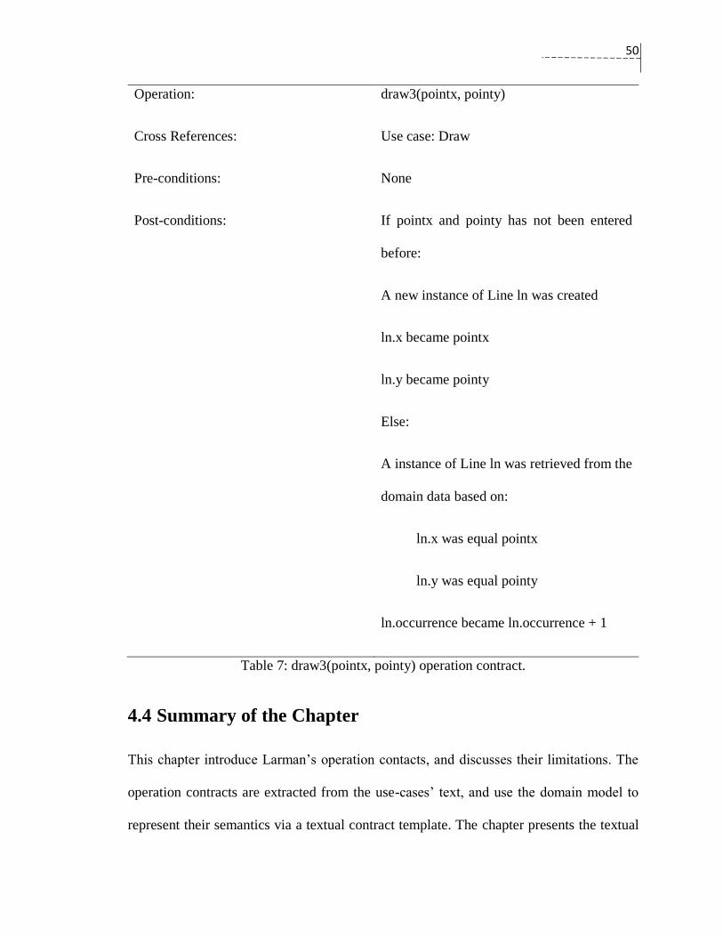
50
Operation: draw3(pointx, pointy)
Cross References: Use case: Draw
Pre-conditions: None
Post-conditions: If pointx and pointy has not been entered
before:
A new instance of Line ln was created
ln.x became pointx
ln.y became pointy
Else:
A instance of Line ln was retrieved from the
domain data based on:
ln.x was equal pointx
ln.y was equal pointy
ln.occurrence became ln.occurrence + 1
Table 7: draw3(pointx, pointy) operation contract.
4.4 Summary of the Chapter
This chapter introduce Larman’s operation contacts, and discusses their limitations. The
operation contracts are extracted from the use-cases’ text, and use the domain model to
represent their semantics via a textual contract template. The chapter presents the textual

51
template of the operation contracts, and explains it with illustrative examples. Finally, the
chapter discusses some limitations in the operation contracts.
The limitation of Larman’s operation contracts can be attributed to three main factors. First,
Larman’s operation contracts does not have a visual representation despite of the advantage
of visual representation in the comprehension and the memory utilization of the human
mind. Second, Larman’s operation contracts does not provide constructs for aspect that are
frequently are used in the operation contracts such as expressing data constraints, and
operations’ alternatives. Third, the create statement of Larman’s operation contract is
limited only for describing domain objects that add new data to the domain. Software
developers use their own ways to clarify how data are associated to the domain objects.
This imposes the need to use more precise syntaxes that clarify the relationship between
domain objects and their data for Larman’s operation contracts.
52
Chapter 5: Visual Operation
Contract
Larman extols the virtues of the operation contracts as to deepen the understanding of
software systems in early software requirement. The considerable merit of using the
operation contracts can be further realized by the proposed visual operation contract. Our
approach complements the text-based operation contracts by offering a visual
representation. The visual representation of the visual operation contract has a limited
number of visual elements. As a design principle, we tried to reuse available UML symbols
as possible, and we limit introducing new notations only for semantics that do not have a
corresponding notation in UML. The effectiveness, or more precisely “the cognitive
effectiveness”, of the proposed visual approach is guided by the Physics of Notation theory,
which is a leading approach for designing and evaluating visual models in the software
engineering discipline. The degree of the cognitive effectiveness of the visual operation
contract seems very acceptable for most of the principles of the Physics of Notation.
Our approach offers a transformation from the visual operation contracts to Larman’s
operation contracts. The textual representation of the visual operation contract enhances
the syntax of Larman’s operation contracts and improves the structured language
description of Larman’s operation contracts. The enhanced syntax introduces new
53
keywords, which are capable of describing the created object in terms of whether they
represent persistent or transient data. In addition, the proposed approach allows the
expression of data constraints and alternatives in the operation contracts.
This chapter highlights the following points: the motivations of the visual operation
contract, the improvements done to Larman's contracts, the meta-model, and the cognitive
effectiveness of the visual operation contract.
5.1 Motivations of a Visual notation for Larman’s Operation
Contracts
There are three main objectives for visual operation contract, which are improving the
understanding of the software domain, complementing Larman’s textual operation
contracts, and assisting in the writing of DbC programming contracts. These motivations
will be discussed in the following subsections.
5.1.1 Improving the Domain Model
We are expecting an improvement in understanding the software domain when the visual
operation contract is used. The improvement will be similar to the use of textual operation
contracts, but the visual operation contract offers more benefits. The impact of using
Larman’s operation contracts along with sequence diagrams was investigated by Briand et
al. and it shows improvement of the quality of the domain model (Briand, Labiche, &
Madrazo-Rivera, 2011). Their experiment on students in fourth-year software course
shows a modest increase (from 4% to 6%) in understanding the domain by complementing
sequence diagrams with Larman operation contracts. However, the selection of two non-
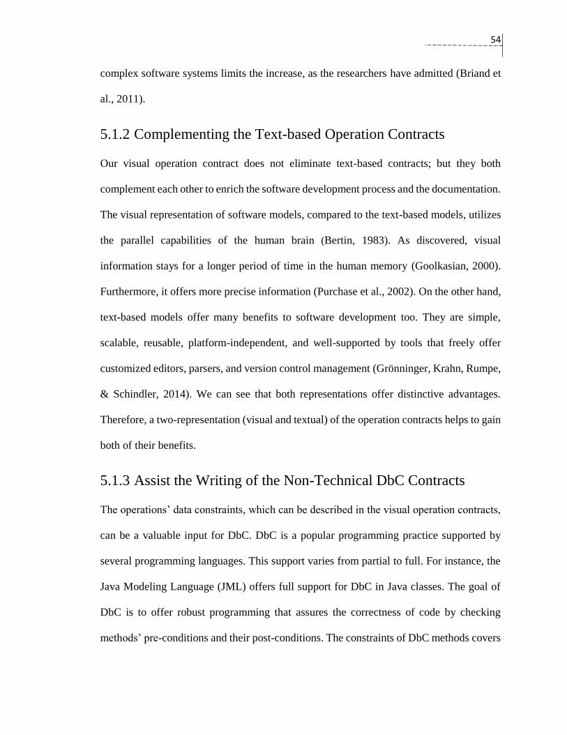
54
complex software systems limits the increase, as the researchers have admitted (Briand et
al., 2011).
5.1.2 Complementing the Text-based Operation Contracts
Our visual operation contract does not eliminate text-based contracts; but they both
complement each other to enrich the software development process and the documentation.
The visual representation of software models, compared to the text-based models, utilizes
the parallel capabilities of the human brain (Bertin, 1983). As discovered, visual
information stays for a longer period of time in the human memory (Goolkasian, 2000).
Furthermore, it offers more precise information (Purchase et al., 2002). On the other hand,
text-based models offer many benefits to software development too. They are simple,
scalable, reusable, platform-independent, and well-supported by tools that freely offer
customized editors, parsers, and version control management (Grönninger, Krahn, Rumpe,
& Schindler, 2014). We can see that both representations offer distinctive advantages.
Therefore, a two-representation (visual and textual) of the operation contracts helps to gain
both of their benefits.
5.1.3 Assist the Writing of the Non-Technical DbC Contracts
The operations’ data constraints, which can be described in the visual operation contracts,
can be a valuable input for DbC. DbC is a popular programming practice supported by
several programming languages. This support varies from partial to full. For instance, the
Java Modeling Language (JML) offers full support for DbC in Java classes. The goal of
DbC is to offer robust programming that assures the correctness of code by checking
methods’ pre-conditions and their post-conditions. The constraints of DbC methods covers
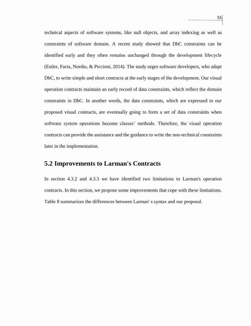
55
technical aspects of software systems, like null objects, and array indexing as well as
constraints of software domain. A recent study showed that DbC constraints can be
identified early and they often remains unchanged through the development lifecycle
(Estler, Furia, Nordio, & Piccioni, 2014). The study urges software developers, who adapt
DbC, to write simple and short contracts at the early stages of the development. Our visual
operation contracts maintain an early record of data constraints, which reflect the domain
constraints in DbC. In another words, the data constraints, which are expressed in our
proposed visual contracts, are eventually going to form a set of data constraints when
software system operations become classes’ methods. Therefore, the visual operation
contracts can provide the assistance and the guidance to write the non-technical constraints
later in the implementation.
5.2 Improvements to Larman's Contracts
In section 4.3.2 and 4.3.3 we have identified two limitations to Larman's operation
contracts. In this section, we propose some improvements that cope with these limitations.
Table 8 summarizes the differences between Larman' s syntax and our proposal.

56
Scope Larman’ syntax Proposed syntax
Domain instance creation Yes. A generic statement is
used.
Yes. A detailed statement that
specifies temporal and persistency
of data.
Data retrieval No. Yes. A specific form of domain
instance creation. Data can be
retrieved through domain objects.
Association formation Yes Yes, we use Larman’s syntax.
Association deletion Yes Yes, we use Larman’s syntax.
Type of association (inheritance,
composition, and aggregation).
No. No.
Domain instance deletion Yes. Yes, we use Larman’s syntax.
Operation’s alternatives No. Yes.
Data constraints No. Yes.
Collection operations No. No.
Table 8: Comparison between our proposal and Larman' syntax.
5.2.1 Structuring Syntax for Important Aspects of System
Operations
Although the syntax of Larman’s operation contracts offers guidelines to express the
creation and deletion of domain objects, modifications of attributes, and formation and
deletion of associations, the syntax remain very informal particularly on two important
aspects. The first aspect is conditional outcomes in post-conditions. The post-condition of
an operation contract might have alternative of outcomes, which are based on certain
conditions. For this purpose, we propose a structured construct that will be introduced in
the alternative component. The second aspect is the expression of data constraints of
operation contracts’ parameters, and attributes. The comparison component will discuss a
more formal way for expressing such constraints.

57
5.2.2 Describing Temporal and Persistency of Domain Objects
The creation statement in Larman’s operation contracts describes the addition of new
objects by the new keyword. The new keyword is insufficient to describe two types:
temporary objects and retrieved objects. Therefore, we introduced two keywords:
temporary and retrieved to distinguish between these two types. The types of domain
objects can be listed as:
1. New objects: Domain objects that add new data to the stored data after performing
the operation;
2. Temporary objects: Domain objects that do not affect the stored data after
performing the operation. Their data is not related to the stored data; and
3. Retrieved objects: Domain objects that represent copies of the stored data. They
exists before performing the operation.
The keyword temporary will be added to the creation statement in a similar way to the
addition of the new keyword in Larman’s contracts. For instance, the Case1 in section 4.3.3
can be explicitly described by the temporary keyword as in Table 9.
Operation: draw_temp(pointx, pointy)
Cross References: Use case: Draw
Pre-conditions: None
Post-conditions: A temporary instance of Line ln was created
ln.x became pointx
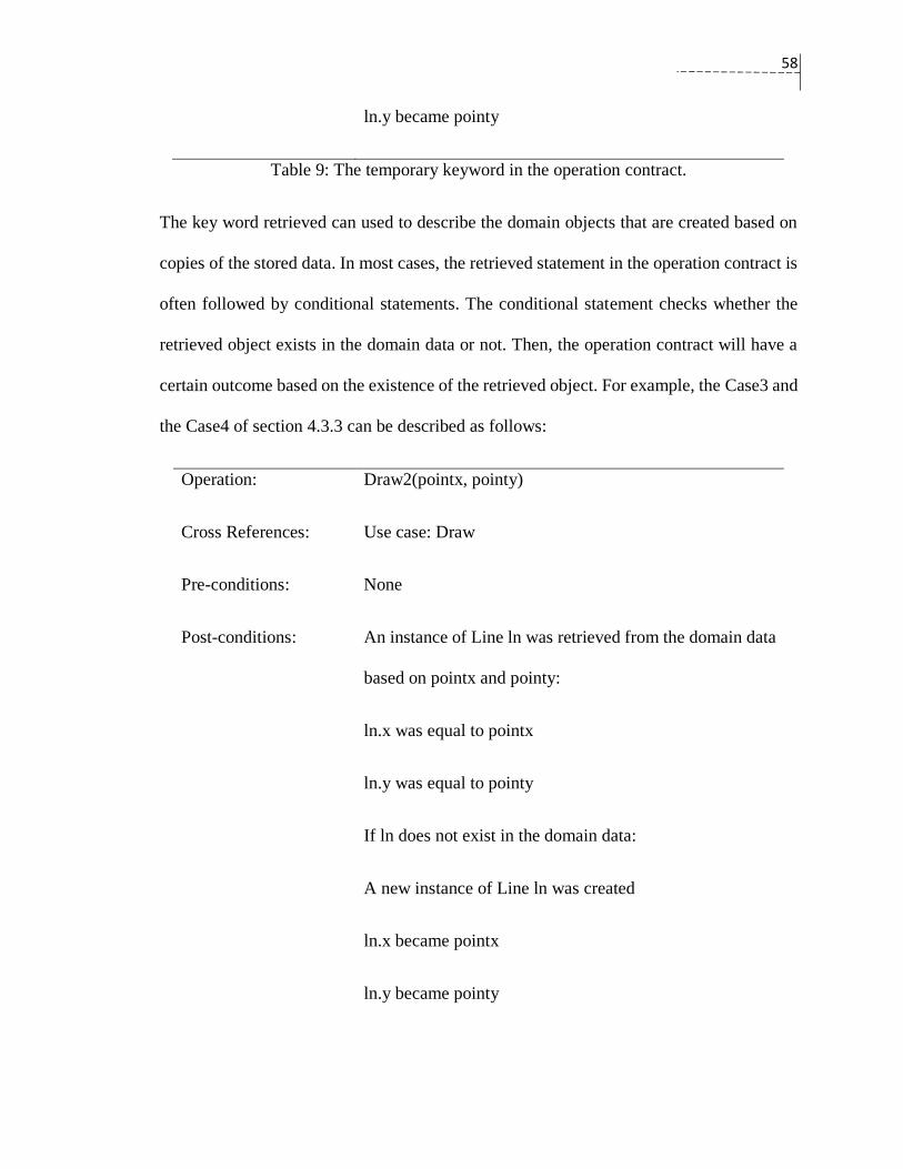
58
ln.y became pointy
Table 9: The temporary keyword in the operation contract.
The key word retrieved can used to describe the domain objects that are created based on
copies of the stored data. In most cases, the retrieved statement in the operation contract is
often followed by conditional statements. The conditional statement checks whether the
retrieved object exists in the domain data or not. Then, the operation contract will have a
certain outcome based on the existence of the retrieved object. For example, the Case3 and
the Case4 of section 4.3.3 can be described as follows:
Operation: Draw2(pointx, pointy)
Cross References: Use case: Draw
Pre-conditions: None
Post-conditions: An instance of Line ln was retrieved from the domain data
based on pointx and pointy:
ln.x was equal to pointx
ln.y was equal to pointy
If ln does not exist in the domain data:
A new instance of Line ln was created
ln.x became pointx
ln.y became pointy
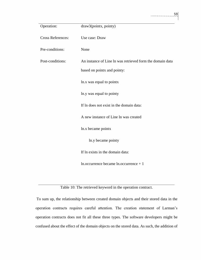
59
Operation: draw3(pointx, pointy)
Cross References: Use case: Draw
Pre-conditions: None
Post-conditions: An instance of Line ln was retrieved form the domain data
based on pointx and pointy:
ln.x was equal to pointx
ln.y was equal to pointy
If ln does not exist in the domain data:
A new instance of Line ln was created
ln.x became pointx
ln.y became pointy
If ln exists in the domain data:
ln.occurrence became ln.occurrence + 1
Table 10: The retrieved keyword in the operation contract.
To sum up, the relationship between created domain objects and their stored data in the
operation contracts requires careful attention. The creation statement of Larman’s
operation contracts does not fit all these three types. The software developers might be
confused about the effect of the domain objects on the stored data. As such, the addition of
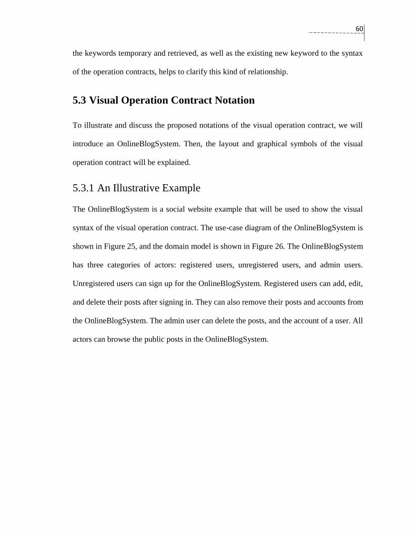
60
the keywords temporary and retrieved, as well as the existing new keyword to the syntax
of the operation contracts, helps to clarify this kind of relationship.
5.3 Visual Operation Contract Notation
To illustrate and discuss the proposed notations of the visual operation contract, we will
introduce an OnlineBlogSystem. Then, the layout and graphical symbols of the visual
operation contract will be explained.
5.3.1 An Illustrative Example
The OnlineBlogSystem is a social website example that will be used to show the visual
syntax of the visual operation contract. The use-case diagram of the OnlineBlogSystem is
shown in Figure 25, and the domain model is shown in Figure 26. The OnlineBlogSystem
has three categories of actors: registered users, unregistered users, and admin users.
Unregistered users can sign up for the OnlineBlogSystem. Registered users can add, edit,
and delete their posts after signing in. They can also remove their posts and accounts from
the OnlineBlogSystem. The admin user can delete the posts, and the account of a user. All
actors can browse the public posts in the OnlineBlogSystem.

61
Figure 25: The OnlineBlogSystem use-case diagram.
The focus will be on some system operations in the OnlineBlogSystem. These operations
are extracted from these use-cases: add post use-case, sign up use-case, delete user’s
account use-case, delete post use-case, and delete account use-case. The description of
these use-cases is presented in Figure 27 to Figure 31. The system operations for the sign
up use-case are addUserAccountSelection(), and addNewRegisteredUser(username,
password, email, name). The add post use-case has two system operations:
addNewPostSelection(), and addPost(postTitle, postContent) . The delete account use-case
has the following system operations: deleteAccountSelection() and deleteAccount(). The
delete user’s account use-case contains three system operations: deleteAccountSelection(),
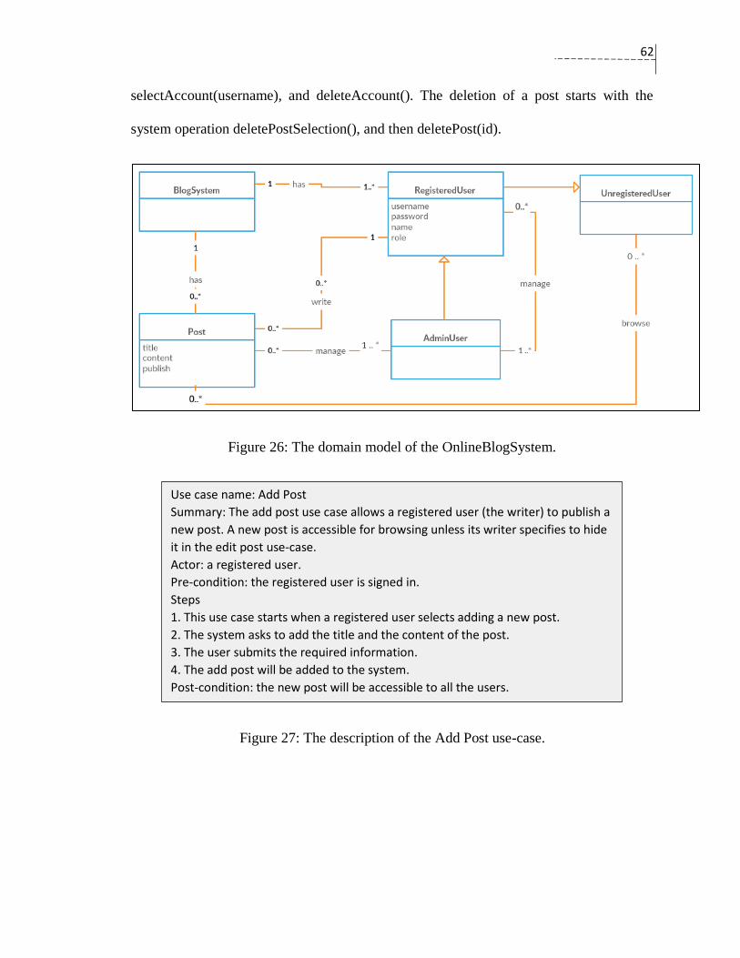
62
selectAccount(username), and deleteAccount(). The deletion of a post starts with the
system operation deletePostSelection(), and then deletePost(id).
Figure 26: The domain model of the OnlineBlogSystem.
Figure 27: The description of the Add Post use-case.
Use case name: Add Post
Summary: The add post use case allows a registered user (the writer) to publish a
new post. A new post is accessible for browsing unless its writer specifies to hide
it in the edit post use-case.
Actor: a registered user.
Pre-condition: the registered user is signed in.
Steps
1. This use case starts when a registered user selects adding a new post.
2. The system asks to add the title and the content of the post.
3. The user submits the required information.
4. The add post will be added to the system.
Post-condition: the new post will be accessible to all the users.
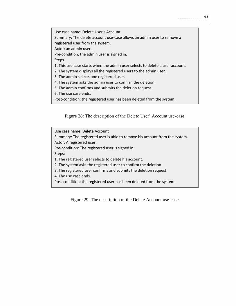
63
Figure 28: The description of the Delete User’ Account use-case.
Figure 29: The description of the Delete Account use-case.
Use case name: Delete User’s Account
Summary: The delete account use-case allows an admin user to remove a
registered user from the system.
Actor: an admin user.
Pre-condition: the admin user is signed in.
Steps
1. This use case starts when the admin user selects to delete a user account.
2. The system displays all the registered users to the admin user.
3. The admin selects one registered user.
4. The system asks the admin user to confirm the deletion.
5. The admin confirms and submits the deletion request.
6. The use case ends.
Post-condition: the registered user has been deleted from the system.
Use case name: Delete Account
Summary: The registered user is able to remove his account from the system.
Actor: A registered user.
Pre-condition: The registered user is signed in.
Steps:
1. The registered user selects to delete his account.
2. The system asks the registered user to confirm the deletion.
3. The registered user confirms and submits the deletion request.
4. The use case ends.
Post-condition: the registered user has been deleted from the system.
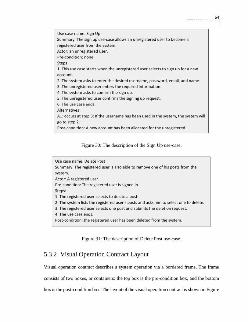
64
Figure 30: The description of the Sign Up use-case.
Figure 31: The description of Delete Post use-case.
5.3.2 Visual Operation Contract Layout
Visual operation contract describes a system operation via a bordered frame. The frame
consists of two boxes, or containers: the top box is the pre-condition box, and the bottom
box is the post-condition box. The layout of the visual operation contract is shown in Figure
Use case name: Sign Up
Summary: The sign up use-case allows an unregistered user to become a
registered user from the system.
Actor: an unregistered user.
Pre-condition: none.
Steps
1. This use case starts when the unregistered user selects to sign up for a new
account.
2. The system asks to enter the desired username, password, email, and name.
3. The unregistered user enters the required information.
4. The system asks to confirm the sign up.
5. The unregistered user confirms the signing up request.
6. The use case ends.
Alternatives
A1: occurs at step 3: If the username has been used in the system, the system will
go to step 2.
Post-condition: A new account has been allocated for the unregistered.
Use case name: Delete Post
Summary: The registered user is also able to remove one of his posts from the
system.
Actor: A registered user.
Pre-condition: The registered user is signed in.
Steps:
1. The registered user selects to delete a post.
2. The system lists the registered user’s posts and asks him to select one to delete.
3. The registered user selects one post and submits the deletion request.
4. The use case ends.
Post-condition: the registered user has been deleted from the system.
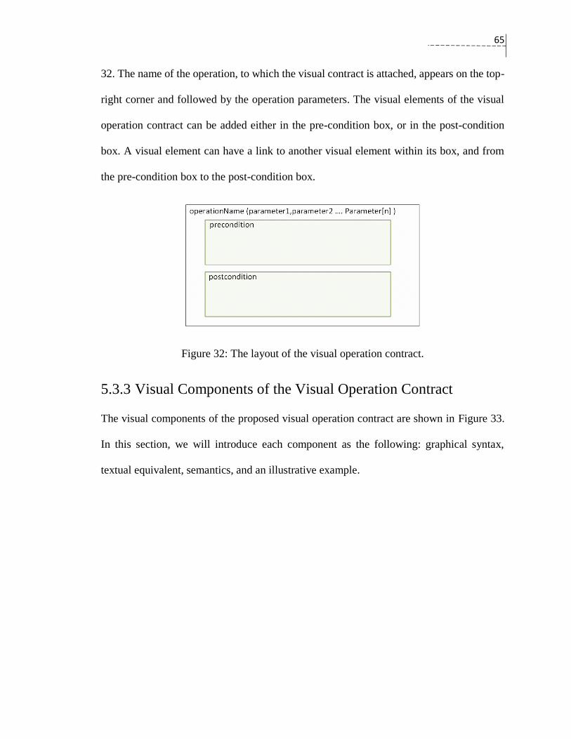
65
32. The name of the operation, to which the visual contract is attached, appears on the top-
right corner and followed by the operation parameters. The visual elements of the visual
operation contract can be added either in the pre-condition box, or in the post-condition
box. A visual element can have a link to another visual element within its box, and from
the pre-condition box to the post-condition box.
Figure 32: The layout of the visual operation contract.
5.3.3 Visual Components of the Visual Operation Contract
The visual components of the proposed visual operation contract are shown in Figure 33.
In this section, we will introduce each component as the following: graphical syntax,
textual equivalent, semantics, and an illustrative example.
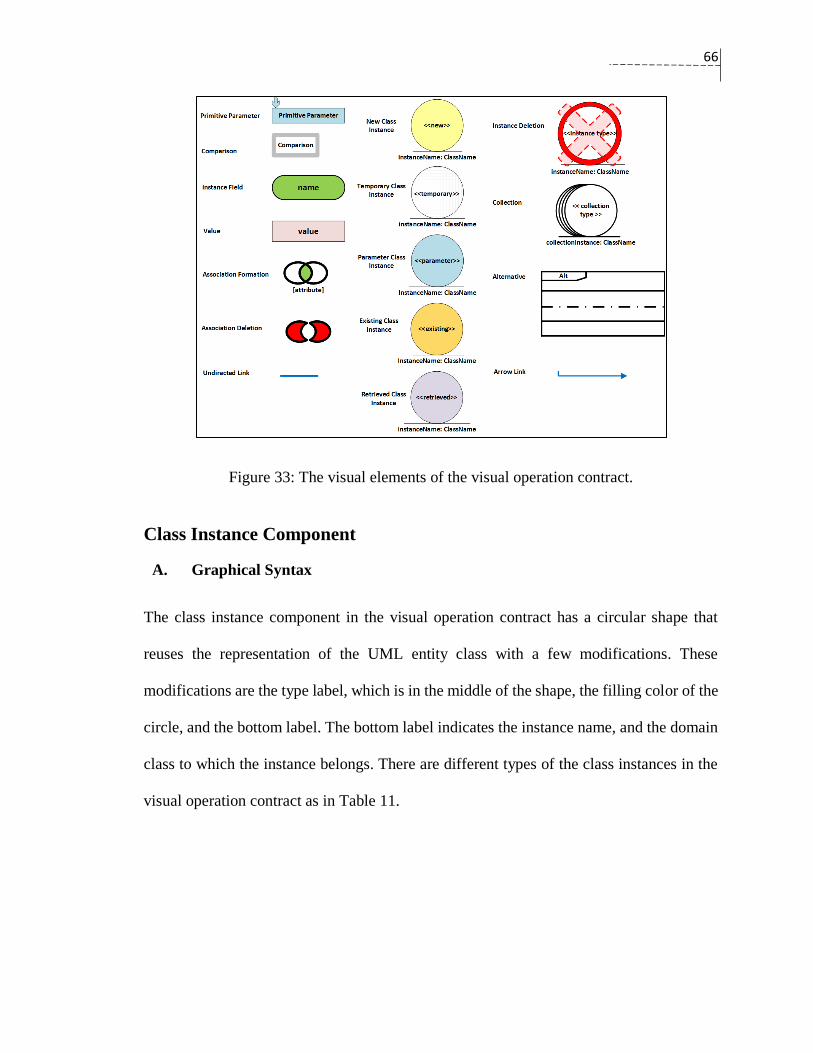
66
Figure 33: The visual elements of the visual operation contract.
Class Instance Component
A. Graphical Syntax
The class instance component in the visual operation contract has a circular shape that
reuses the representation of the UML entity class with a few modifications. These
modifications are the type label, which is in the middle of the shape, the filling color of the
circle, and the bottom label. The bottom label indicates the instance name, and the domain
class to which the instance belongs. There are different types of the class instances in the
visual operation contract as in Table 11.
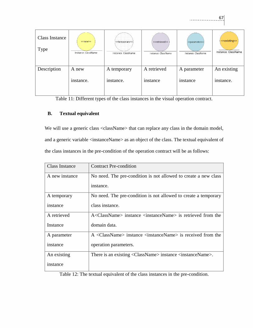
67
Class Instance
Type
Description
A new
instance.
A temporary
instance.
A retrieved
instance
A parameter
instance
An existing
instance.
Table 11: Different types of the class instances in the visual operation contract.
B. Textual equivalent
We will use a generic class <className> that can replace any class in the domain model,
and a generic variable <instanceName> as an object of the class. The textual equivalent of
the class instances in the pre-condition of the operation contract will be as follows:
Class Instance Contract Pre-condition
A new instance No need. The pre-condition is not allowed to create a new class
instance.
A temporary
instance
No need. The pre-condition is not allowed to create a temporary
class instance.
A retrieved
Instance
A<ClassName> instance <instanceName> is retrieved from the
domain data.
A parameter
instance
A <ClassName> instance <instanceName> is received from the
operation parameters.
An existing
instance
There is an existing <ClassName> instance <instanceName>.
Table 12: The textual equivalent of the class instances in the pre-condition.

68
The textual equivalent of the class instances in the post-condition of the operation contract
is as follows:
Class Instance Contract Post-condition
A new instance A <ClassName> new instance <instanceName> was created.
A temporary
instance
A <ClassName> temporary instance <instanceName> was
created.
A retrieved
Instance
A <ClassName> instance <instanceName> was retrieved from the
domain data.
A parameter
instance
A <ClassName> instance of <instanceName> was received from
the operation parameters.
An existing
instance
There was an existing<ClassName> instance <instanceName>.
Table 13: The textual equivalent of the class instances in the post-condition.
C. Semantics
There are five types of the class instance component that can be used in the visual operation
contract. The first three types (new class instances, temporary class instances, and retrieved
class instances) describe creating new domain objects with different stored data
perspectives. The last two types deal with received class instances. The parameter class
instance refers to a domain object that is received through the operation parameters. The
existing class instance can be used when the system operations follow a specific sequence:
and the post-condition of one operation is supplied to the pre-condition of the next
operation. In these cases, it refers to a domain object that is created in a post-condition of
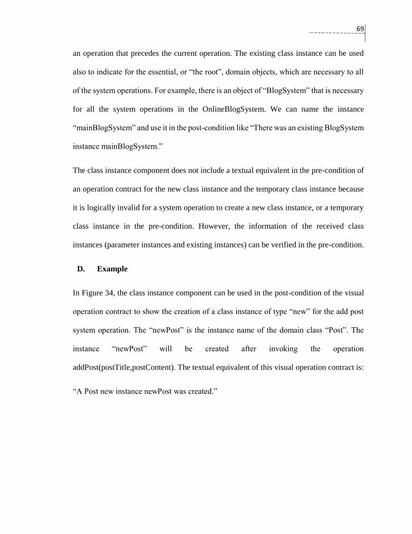
69
an operation that precedes the current operation. The existing class instance can be used
also to indicate for the essential, or “the root”, domain objects, which are necessary to all
of the system operations. For example, there is an object of “BlogSystem” that is necessary
for all the system operations in the OnlineBlogSystem. We can name the instance
“mainBlogSystem” and use it in the post-condition like “There was an existing BlogSystem
instance mainBlogSystem.”
The class instance component does not include a textual equivalent in the pre-condition of
an operation contract for the new class instance and the temporary class instance because
it is logically invalid for a system operation to create a new class instance, or a temporary
class instance in the pre-condition. However, the information of the received class
instances (parameter instances and existing instances) can be verified in the pre-condition.
D. Example
In Figure 34, the class instance component can be used in the post-condition of the visual
operation contract to show the creation of a class instance of type “new” for the add post
system operation. The “newPost” is the instance name of the domain class “Post”. The
instance “newPost” will be created after invoking the operation
addPost(postTitle,postContent). The textual equivalent of this visual operation contract is:
“A Post new instance newPost was created.”

70
Figure 34: An example of a new class instance component in visual operation contract.
Instance Deletion Component
A. Graphical syntax
The instance deletion component surrounds the circle of the class instance component with
a red color and has a red cross on the top of the class instance circle. The middle label takes
either “<<retrieved>>” or “<<existing>>” because the instance deletion component can be
used only for retrieved and existing class instances.
Figure 35: Deletion of existing and retrieved instances.
B. Textual equivalent
The deletion of an instance can occur only in the post-condition of the visual operation
contract. That is, the textual equivalent of the instance deletion component:
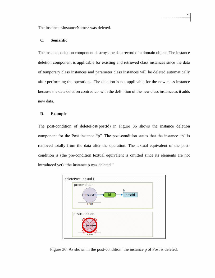
71
The instance <instanceName> was deleted.
C. Semantic
The instance deletion component destroys the data record of a domain object. The instance
deletion component is applicable for existing and retrieved class instances since the data
of temporary class instances and parameter class instances will be deleted automatically
after performing the operations. The deletion is not applicable for the new class instance
because the data deletion contradicts with the definition of the new class instance as it adds
new data.
D. Example
The post-condition of deletePost(postId) in Figure 36 shows the instance deletion
component for the Post instance “p”. The post-condition states that the instance “p” is
removed totally from the data after the operation. The textual equivalent of the post-
condition is (the pre-condition textual equivalent is omitted since its elements are not
introduced yet) “the instance p was deleted.”
Figure 36: As shown in the post-condition, the instance p of Post is deleted.

72
Association Formation Component
A. Graphical Syntax
The association formation component in the visual operation contract is expressed via a
shape that consists of two overlapped ovals. The overlapping area is filled with a green
color. The attribute label is required when there is a certain attribute by which the
association is based. The formation of an association between two domain objects can be
directional, or unidirectional.
Figure 37: The representation of the formation of an association.
B. Textual Equivalent
The textual equivalent of the association formation component in the pre-condition of the
operation contract is one of the following:
<instanceName_1> is associated with a <instanceName_2>
<instanceName_1> is associated with a <instanceName_2>, based on <attribute> match.
The textual equivalent of the association formation component in the post-condition of the
operation contract is one of the following:
<instanceName_1> was associated with a <instanceName_2>
<instanceName_1> was associated with a <instanceName_2>, based on <attribute> match.
C. Semantics
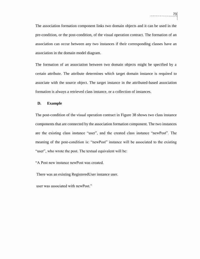
73
The association formation component links two domain objects and it can be used in the
pre-condition, or the post-condition, of the visual operation contract. The formation of an
association can occur between any two instances if their corresponding classes have an
association in the domain model diagram.
The formation of an association between two domain objects might be specified by a
certain attribute. The attribute determines which target domain instance is required to
associate with the source object. The target instance in the attributed-based association
formation is always a retrieved class instance, or a collection of instances.
D. Example
The post-condition of the visual operation contract in Figure 38 shows two class instance
components that are connected by the association formation component. The two instances
are the existing class instance “user”, and the created class instance “newPost”. The
meaning of the post-condition is: “newPost” instance will be associated to the existing
“user”, who wrote the post. The textual equivalent will be:
“A Post new instance newPost was created.
There was an existing RegisteredUser instance user.
user was associated with newPost.”
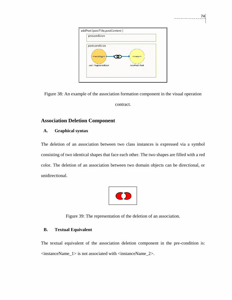
74
Figure 38: An example of the association formation component in the visual operation
contract.
Association Deletion Component
A. Graphical syntax
The deletion of an association between two class instances is expressed via a symbol
consisting of two identical shapes that face each other. The two shapes are filled with a red
color. The deletion of an association between two domain objects can be directional, or
unidirectional.
Figure 39: The representation of the deletion of an association.
B. Textual Equivalent
The textual equivalent of the association deletion component in the pre-condition is:
<instanceName_1> is not associated with <instanceName_2>.
75
The textual equivalent of the association deletion component in the post-condition is as
follows:
<instanceName_1> was disassociated from <instanceName_2>.
C. Semantics
The association deletion component breaks the association between the two domain
objects. The deletion of an association can occur between any two instances if they have
an association on their corresponding classes in the domain model. In fact, the deletion of
an association cannot occur in the pre-condition; however, it is possible to verify that there
is no association between two class instances in the pre-condition.
D. Example
The association deletion component can be used to visualize the operation contract of
deleteAccount(), in which a registered user can delete his or her own account. The visual
operation contract of deleteAccount() is presented in Figure 40. The textual equivalent is:
“There was an existing RegisteredUser instance user.
There was an existing BlogSytem instance system.
user was disassociated from BlogSytem”
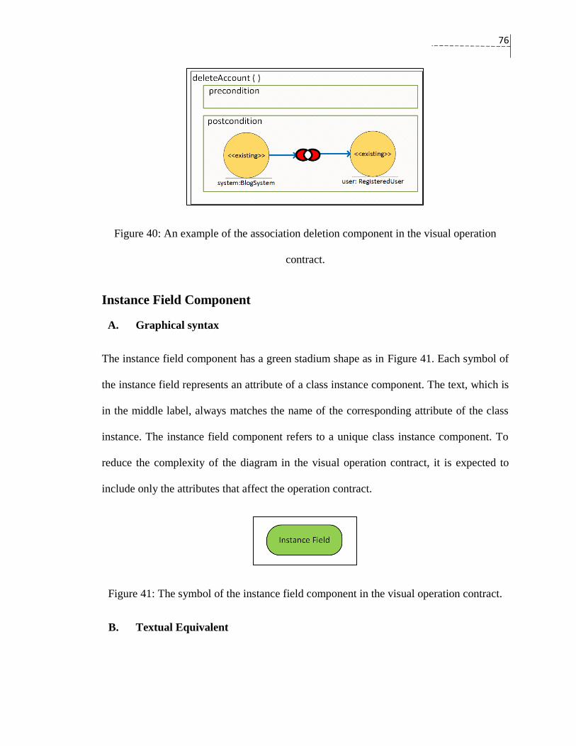
76
Figure 40: An example of the association deletion component in the visual operation
contract.
Instance Field Component
A. Graphical syntax
The instance field component has a green stadium shape as in Figure 41. Each symbol of
the instance field represents an attribute of a class instance component. The text, which is
in the middle label, always matches the name of the corresponding attribute of the class
instance. The instance field component refers to a unique class instance component. To
reduce the complexity of the diagram in the visual operation contract, it is expected to
include only the attributes that affect the operation contract.
Figure 41: The symbol of the instance field component in the visual operation contract.
B. Textual Equivalent

77
The instance field component does not form a complete line in the textual operation
contracts by itself. It forms the beginning, or middle part, of a sentence in the pre-condition,
or in the post-condition. The tag <Instance-field-text> will be used to indicate the textual
equivalent of the instance field component. The <Instance-field-text> refers to an attribute
<instanceAttribute> of a class instance <instanceName>. The formal textual equivalent can
be written as:
<Instance-field-text>::=<instanceName> ,”.”, < instanceAttribute>.
C. Semantics
The instance field component specifies an attribute < instanceAttribute> of a class instance,
<instanceName>, for two purposes in the visual operation contract. Firstly, the instance
field component is essential to form a visual representation for attribute modification of the
class instances. Secondly, the instance field component can be used to verify the data of
the attributes of the parameter class instances and the retrieved class instances.
D. Example
Figure 42 shows that the instance field components are used to demonstrate two attributes
of the class instance “newPost”. the instance field component does not provide any
meaning in the visual contract unless they are connected to a class instance component.

78
Figure 42: Two instance field components show two attributes of the domain class
“Post”.
Parameter Component
A. Graphical Syntax
The visual operation contract allows representing the specifications of the operation
parameters in two ways: a blue rectangle for the primitive parameters as in
Figure 43, and a parameter class instance for the class instance parameters (shown in a
parameter instance in Table 11). The primitive parameter carries basic data types such as
numbers, boolean values, and strings. The class instance parameter is the type in which the
operation receives a class instance in its signature. The class instance parameter was
introduced in Class Instance Component (section 0). The name of the parameter component
for both types must match the name of the corresponding operation parameter.
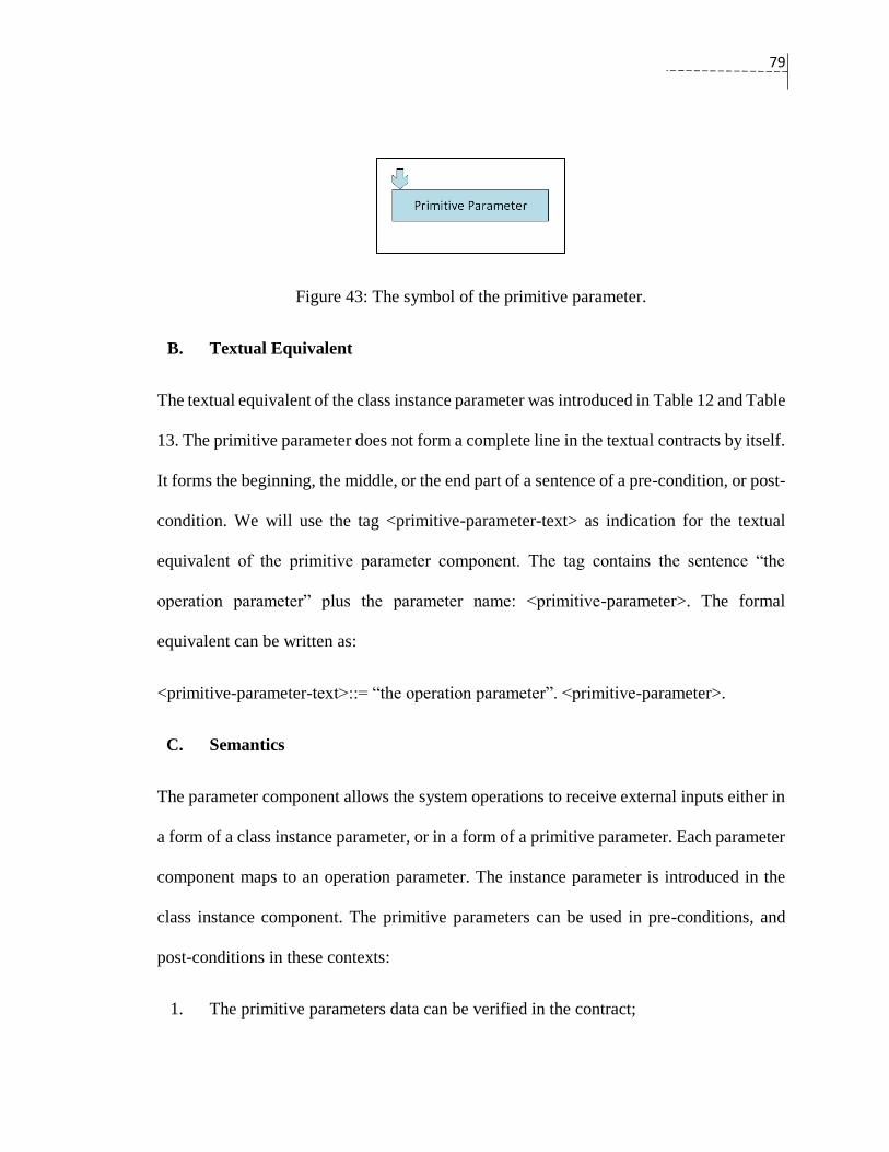
79
Figure 43: The symbol of the primitive parameter.
B. Textual Equivalent
The textual equivalent of the class instance parameter was introduced in Table 12 and Table
13. The primitive parameter does not form a complete line in the textual contracts by itself.
It forms the beginning, the middle, or the end part of a sentence of a pre-condition, or post-
condition. We will use the tag <primitive-parameter-text> as indication for the textual
equivalent of the primitive parameter component. The tag contains the sentence “the
operation parameter” plus the parameter name: <primitive-parameter>. The formal
equivalent can be written as:
<primitive-parameter-text>::= “the operation parameter”. <primitive-parameter>.
C. Semantics
The parameter component allows the system operations to receive external inputs either in
a form of a class instance parameter, or in a form of a primitive parameter. Each parameter
component maps to an operation parameter. The instance parameter is introduced in the
class instance component. The primitive parameters can be used in pre-conditions, and
post-conditions in these contexts:
1. The primitive parameters data can be verified in the contract;
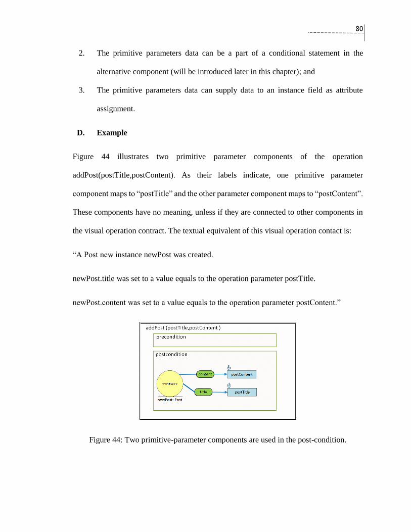
80
2. The primitive parameters data can be a part of a conditional statement in the
alternative component (will be introduced later in this chapter); and
3. The primitive parameters data can supply data to an instance field as attribute
assignment.
D. Example
Figure 44 illustrates two primitive parameter components of the operation
addPost(postTitle,postContent). As their labels indicate, one primitive parameter
component maps to “postTitle” and the other parameter component maps to “postContent”.
These components have no meaning, unless if they are connected to other components in
the visual operation contract. The textual equivalent of this visual operation contact is:
“A Post new instance newPost was created.
newPost.title was set to a value equals to the operation parameter postTitle.
newPost.content was set to a value equals to the operation parameter postContent.”
Figure 44: Two primitive-parameter components are used in the post-condition.
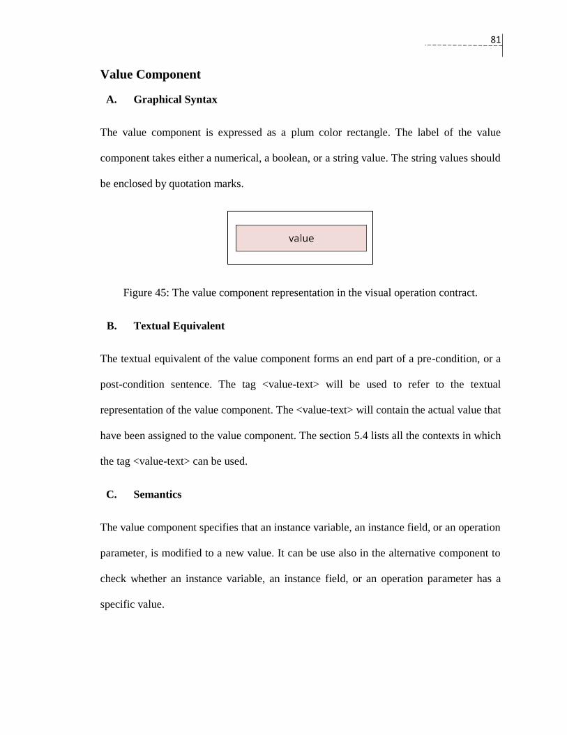
81
Value Component
A. Graphical Syntax
The value component is expressed as a plum color rectangle. The label of the value
component takes either a numerical, a boolean, or a string value. The string values should
be enclosed by quotation marks.
Figure 45: The value component representation in the visual operation contract.
B. Textual Equivalent
The textual equivalent of the value component forms an end part of a pre-condition, or a
post-condition sentence. The tag <value-text> will be used to refer to the textual
representation of the value component. The <value-text> will contain the actual value that
have been assigned to the value component. The section 5.4 lists all the contexts in which
the tag <value-text> can be used.
C. Semantics
The value component specifies that an instance variable, an instance field, or an operation
parameter, is modified to a new value. It can be use also in the alternative component to
check whether an instance variable, an instance field, or an operation parameter has a
specific value.
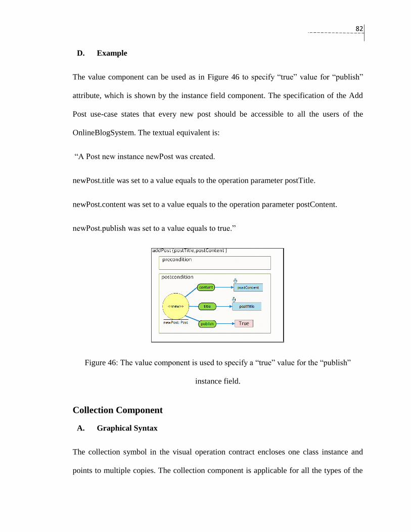
82
D. Example
The value component can be used as in Figure 46 to specify “true” value for “publish”
attribute, which is shown by the instance field component. The specification of the Add
Post use-case states that every new post should be accessible to all the users of the
OnlineBlogSystem. The textual equivalent is:
“A Post new instance newPost was created.
newPost.title was set to a value equals to the operation parameter postTitle.
newPost.content was set to a value equals to the operation parameter postContent.
newPost.publish was set to a value equals to true.”
Figure 46: The value component is used to specify a “true” value for the “publish”
instance field.
Collection Component
A. Graphical Syntax
The collection symbol in the visual operation contract encloses one class instance and
points to multiple copies. The collection component is applicable for all the types of the

83
class instances that were introduced in Table 11. Figure 47 shows the collection component
for a generic class instance of type “new”.
Figure 47: The collection representation of a class instance of type “new”.
B. Textual Equivalent
The textual equivalent of the collection component is similar to the textual equivalent of
the class instances except that the word “collection” precedes the word “instance”.
C. Semantics
The collection component has the capability to represent multiple copies of one domain
class. The collection of instances can be created in the operation, received from the
operation parameters, or retrieved from the domain data. It is possible to reason about the
involved class instances in the collection component by the help of the comparison
component and the value component.
D. Example
The collection component can be used to describe the deleteAccountSelection(). Figure 48
shows the pre-condition and the post-condition of the operation. The pre-condition states
that the user must be an admin user. The post-condition states that all registered users will
be presented to the admin user. The textual equivalent will be:

84
Pre-condition:
There is an existing AdminUser instance adminUser.
Post-condition:
A RegisteredUser collection instance userCollection was retrieved from the domain data.
Figure 48: Example of the collection component
Comparison Component
A. Graphical Syntax
The comparison component is expressed via a gray-bordered rectangle. The comparison
component has a label in the middle. The text of the label changes according to the selected
comparison criterion. There are several comparators that can be selected in the comparison
component, including “equal”, “greater than”, “less than”, “greater than and equal” , “ less
than and equal”, and “not equal”. The comparison component can describe further
comparison criteria; for example, the string comparisions “match” , “start_with”, and
“end_with” can be used to handle string comparison.
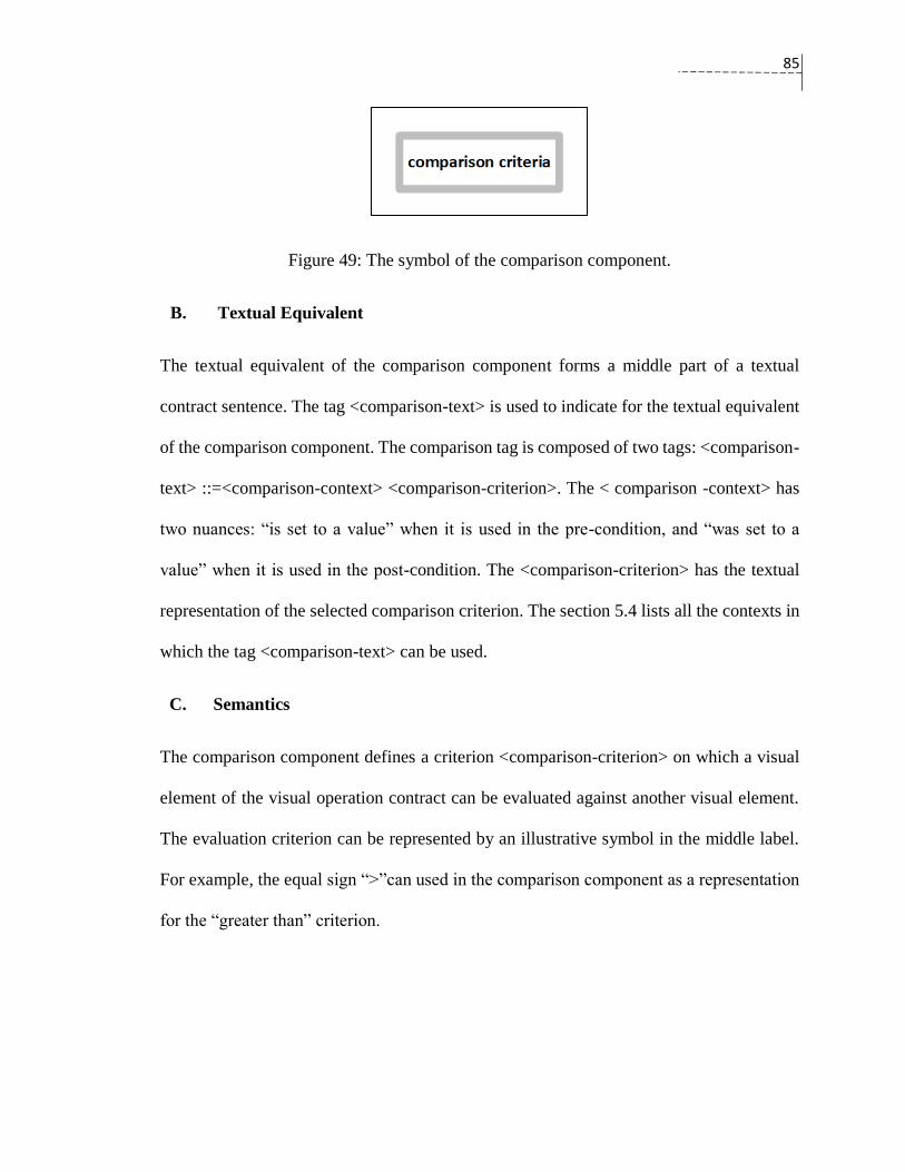
85
Figure 49: The symbol of the comparison component.
B. Textual Equivalent
The textual equivalent of the comparison component forms a middle part of a textual
contract sentence. The tag <comparison-text> is used to indicate for the textual equivalent
of the comparison component. The comparison tag is composed of two tags: <comparison-
text> ::=<comparison-context> <comparison-criterion>. The < comparison -context> has
two nuances: “is set to a value” when it is used in the pre-condition, and “was set to a
value” when it is used in the post-condition. The <comparison-criterion> has the textual
representation of the selected comparison criterion. The section 5.4 lists all the contexts in
which the tag <comparison-text> can be used.
C. Semantics
The comparison component defines a criterion <comparison-criterion> on which a visual
element of the visual operation contract can be evaluated against another visual element.
The evaluation criterion can be represented by an illustrative symbol in the middle label.
For example, the equal sign “>”can used in the comparison component as a representation
for the “greater than” criterion.

86
D. Example
The two primitive parameter components in Figure 50 are connected to comparison
components. Each component has a “greater than” sign that is connected to the primitive
parameter. The two comparison components state the accepted length of characters for the
parameters “postTitle” and “postContent” in the pre-condition. The textual equivalent is:
“Pre-condition:
The operation parameter postTitle is set to a value greater than 5 characters.
The operation parameter postContent is set to a value greater than 200 characters.
Post-condition:
A Post new instance newPost was created.
newPost.title was set to a value equals to the operation parameter postTitle.
newPost.content was set to a value equals to the operation parameter postContent.”
Figure 50: An example of the comparison component in the visual operation contract.

87
Alternative Component
A. Graphical Syntax
The alternative component is a container composed of horizontal divisions. Each division
has a condition section (if statement part), and a body section (if statement body). The
condition section and the body section are separated by a horizontal line. The alternative
component reuses the representation of the UML alternative fragment with few
modifications.
Figure 51: The alternative component in the visual operation contract.
B. Textual Equivalent
The formal textual equivalent of the alternative component in the pre-condition of the
operation contract is as follows:
<if-statement-sentence-pre>::= {“If (“,<comparison-sentence>”): ”, {<line><pre-
condition-statement>}}.
The formal textual equivalent of the alternative component in the post-condition of the
operation contract will be as follows:

88
<if-statement-sentence-post>::= {“If (“,<comparison-sentence>,”): “,{<line><post-
condition-statement>}}.
The <comparison-sentence> forms conditional statements similar to if-else-if statement in
programming languages. The <line> is an empty line that separates the body part from the
condition part. The tag <pre-condition-statement> and the tag <post-condition-statement>
form the body of the condition statement. The detailed information of these tags can be
found in the section 5.4.
The <comparison-context> of the <comparison-text> in the condition part of the alternative
component is: “is” in the pre-condition, and “was” in the post-condition.
C. Semantics
The alternative component allows conditional branching in the visual operation contract.
It is necessary because system operations might have more than one possible outcome. The
alternative component allocates one option block for each outcome. An option block
consists of two parts: a condition part and a body part. The condition part evaluates a
boolean. The body part shows a scenario that will be followed when the condition part is
satisfied. The alternative component can use visual elements out of the alternative box for
its option blocks.
D. Example
The visual operation contract of addRegisteredUser(username, password, email, name) is
illustrated in Figure 52. The alternative component in the visual operation contract shows
that the operation will not create a new account if there is a registered user who has already
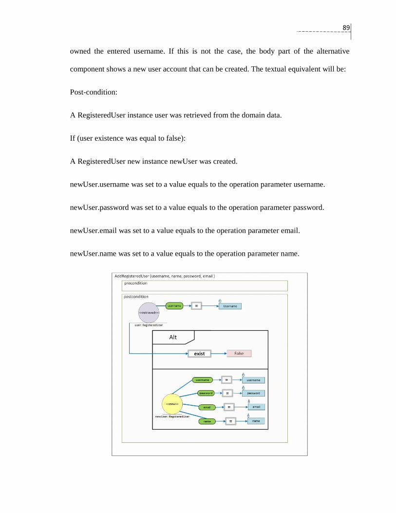
89
owned the entered username. If this is not the case, the body part of the alternative
component shows a new user account that can be created. The textual equivalent will be:
Post-condition:
A RegisteredUser instance user was retrieved from the domain data.
If (user existence was equal to false):
A RegisteredUser new instance newUser was created.
newUser.username was set to a value equals to the operation parameter username.
newUser.password was set to a value equals to the operation parameter password.
newUser.email was set to a value equals to the operation parameter email.
newUser.name was set to a value equals to the operation parameter name.
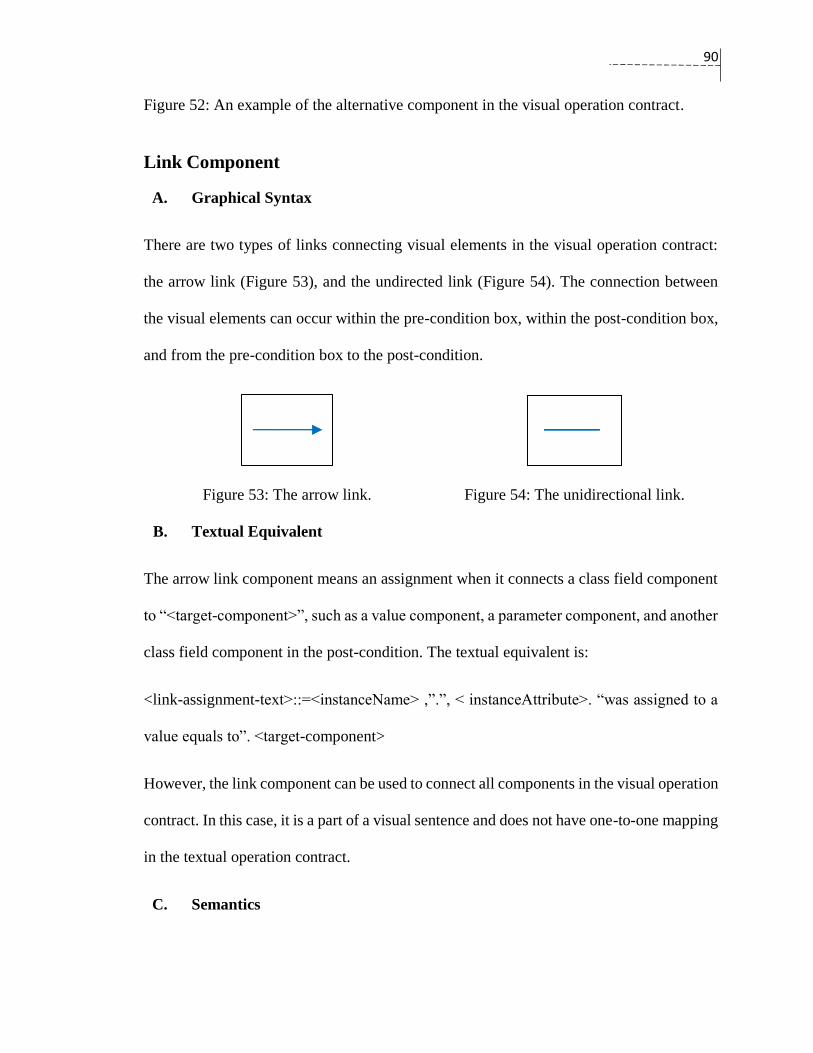
90
Figure 52: An example of the alternative component in the visual operation contract.
Link Component
A. Graphical Syntax
There are two types of links connecting visual elements in the visual operation contract:
the arrow link (Figure 53), and the undirected link (Figure 54). The connection between
the visual elements can occur within the pre-condition box, within the post-condition box,
and from the pre-condition box to the post-condition.
Figure 53: The arrow link. Figure 54: The unidirectional link.
B. Textual Equivalent
The arrow link component means an assignment when it connects a class field component
to “<target-component>”, such as a value component, a parameter component, and another
class field component in the post-condition. The textual equivalent is:
<link-assignment-text>::=<instanceName> ,”.”, < instanceAttribute>. “was assigned to a
value equals to”. <target-component>
However, the link component can be used to connect all components in the visual operation
contract. In this case, it is a part of a visual sentence and does not have one-to-one mapping
in the textual operation contract.
C. Semantics
91
The two types of the link component in the visual operation contract connects the visual
elements to form a meaning. In fact, all the visual elements, except the class instance
component, must be linked to other visual components to form the required meaning. The
directed link is introduced in the visual operation contract because of the insufficiency of
undirected links to represent clear meanings for the comparison component, the association
formation component, and the association deletion component. For example, the arrow link
can clarify the source and the target (reading direction) for “>”, and “<”. The link
constraints are explained in section 5.5.1 .

92
5.4 The Textual Template of the Visual Operation Contract
Notation
The textual template of the visual operation contract is described in the Extended Backus–
Naur Form (EBNF) (Standard, 1996). The generation of the textual contract (from the
visual operation contract as the source) is based on this template. The tag <pre-condition-
text> is used to refer to the textual representation of the pre-condition in the visual
operation contract, while the tag <post-condition-text> is used to refer to the textual
representation of the post-condition.
<pre-condition-text>::= "Pre-condition:", {<line><pre-condition-statement>}.
(* {} means repetitions *)
<pre-condition-statement>::= <class-instance-text-pre> | <association-formation-text-pre> |
<association-deletion-text-pre> | <comparison-sentence> |
<if-statement-sentence-pre>
<post-condition-text> ::= "Post-condition:" {<line><post-condition-statement>}.
<post-condition-statement> ::= <class-instance-text-post> | <association-formation-text-post> |
<association-deletion-text-post> | <comparison-sentence> |
<if-statement-sentence-post> | <instance-deletion-sentence>
<class-instance-text-pre> ::=
“A ”, <ClassName> ,” instance “, <instanceName> ,“ is retrieved
from the domain data.”. |
“A ”, <ClassName>,” instance “,<instanceName>,” is received
from the operation parameters.” |
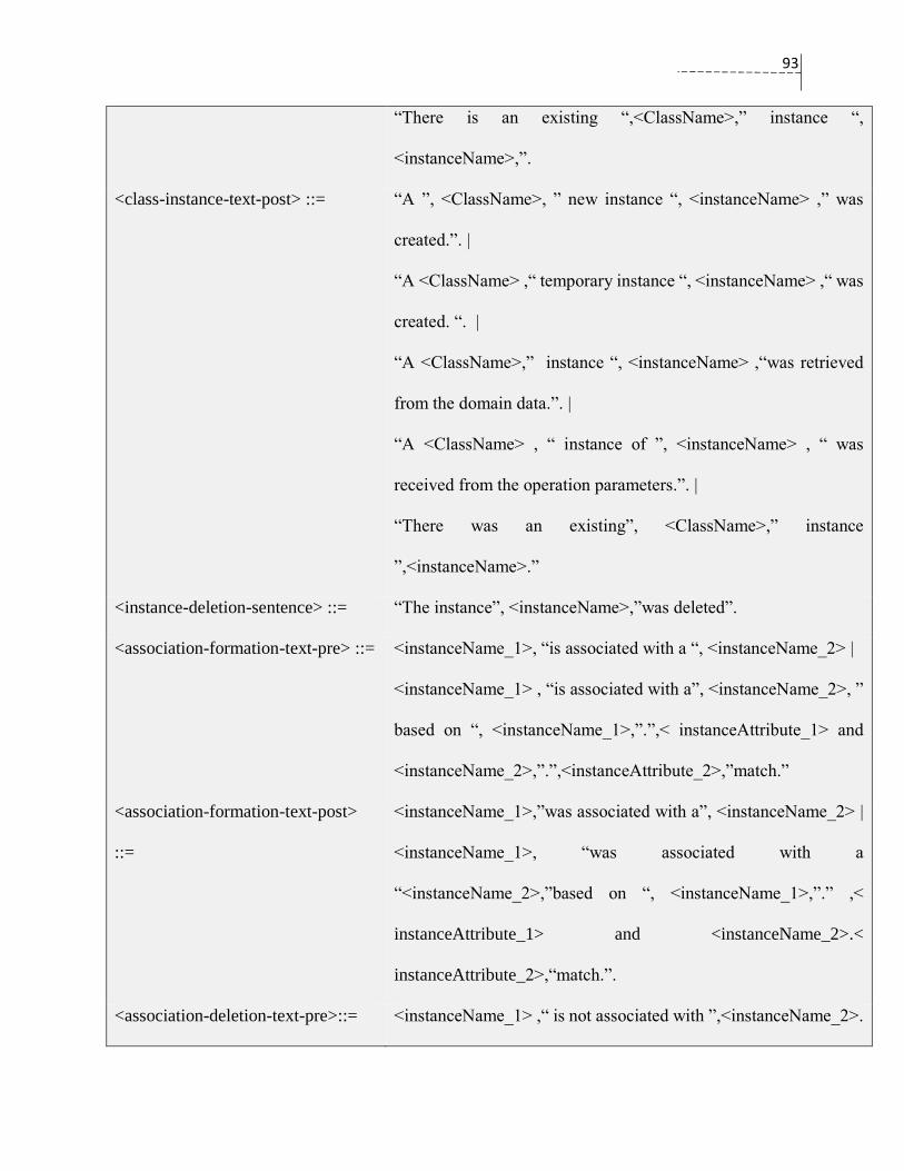
93
“There is an existing “,<ClassName>,” instance “,
<instanceName>,”.
<class-instance-text-post> ::=
“A ”, <ClassName>, ” new instance “, <instanceName> ,” was
created.”. |
“A <ClassName> ,“ temporary instance “, <instanceName> ,“ was
created. “. |
“A <ClassName>,” instance “, <instanceName> ,“was retrieved
from the domain data.”. |
“A <ClassName> , “ instance of ”, <instanceName> , “ was
received from the operation parameters.”. |
“There was an existing”, <ClassName>,” instance
”,<instanceName>.”
<instance-deletion-sentence> ::= “The instance”, <instanceName>,”was deleted”.
<association-formation-text-pre> ::= <instanceName_1>, “is associated with a “, <instanceName_2> |
<instanceName_1> , “is associated with a”, <instanceName_2>, ”
based on “, <instanceName_1>,”.”,< instanceAttribute_1> and
<instanceName_2>,”.”,<instanceAttribute_2>,”match.”
<association-formation-text-post>
::=
<instanceName_1>,”was associated with a”, <instanceName_2> |
<instanceName_1>, “was associated with a
“<instanceName_2>,”based on “, <instanceName_1>,”.” ,<
instanceAttribute_1> and <instanceName_2>.<
instanceAttribute_2>,“match.”.
<association-deletion-text-pre>::= <instanceName_1> ,“ is not associated with ”,<instanceName_2>.

94
<association-deletion-text-post> ::= “The association between ”, <instanceName_1>, “and”,
<instanceName_2> ,“was broken.”.
<comparison-sentence> ::= <instanceName><comparison-text><value-text> |
<instanceName_1><comparison-text><<instanceName_2> |
<Instance-field-text> <comparison-text><value-text> |
<Instance-field-text> <comparison-text><primitive-parameter-
text> | <Instance-field-text> <comparison-text> <Instance-field-
text> |
<primitive-parameter-text><comparison-text><value-text> |
<primitive-parameter-text><comparison-text><primitive-
parameter-text> |
<primitive-parameter-text><comparison-text> <Instance-field-
text>
<if-statement-sentence-pre>::= “If (“,<comparison-sentence>”): ”, {<line><pre-condition-
statement>}.
<if-statement-sentence-post>::= “If (“,<comparison-sentence>,”): “,{<line><post-condition-
statement>}.
<link-assignment-text>::= <instanceName> ,”.”, < instanceAttribute>. “was assigned to a
value equals to”. <Instance-field-text> | <value-text> | <primitive-
parameter-text>
<Instance-field-text> ::= <instanceName> , ”.”, <instanceField>
<instanceName> (* a name that is given for a domain instance*)
<instanceField> (* a name that is given for an attribute of a domain instance*)
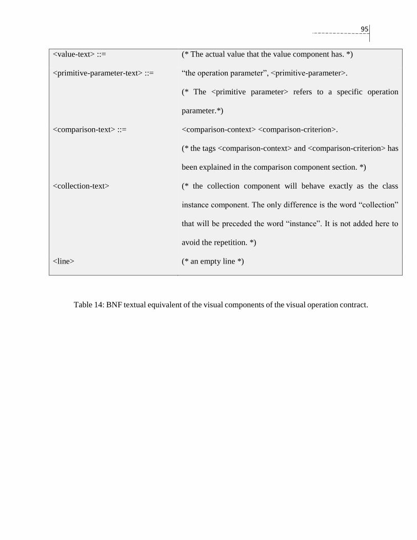
95
<value-text> ::= (* The actual value that the value component has. *)
<primitive-parameter-text> ::=
“the operation parameter”, <primitive-parameter>.
(* The <primitive parameter> refers to a specific operation
parameter.*)
<comparison-text> ::= <comparison-context> <comparison-criterion>.
(* the tags <comparison-context> and <comparison-criterion> has
been explained in the comparison component section. *)
<collection-text> (* the collection component will behave exactly as the class
instance component. The only difference is the word “collection”
that will be preceded the word “instance”. It is not added here to
avoid the repetition. *)
<line> (* an empty line *)
Table 14: BNF textual equivalent of the visual components of the visual operation contract.

96
5.5 Visual Operation Contract Meta-Model
Figure 55 illustrates the meta-model of the visual operation contract. The connection of
visual elements is represented by the class linkComponent in the meta-model. And it
follows certain connection constraints. These constraints specify which visual element can
be a source, which visual element can be a target, and the type of the link that connects the
two elements.
Figure 55: The meta-model of the visual operation contract.

97
5.5.1 Visual Elements Linking Constraints
The connection between visual elements follows certain constraints. These constraints
specify whether it is possible to connect a component to another component. Table 15
shows the possible targets for each source. All visual components are allowed to be
sources, or targets, except the value component, which is always a target component. The
association formation component, the association deletion component, and the comparison
component accept two links: an incoming link and an outgoing link.
The alternative component (represented by the class AlternativeComponent in the meta-
model) has constraints for the option blocks. The option block contains a condition part
and a body part. The condition part always contains at least a comparison component plus
another component. The condition evaluates class instances and their attributes, which are
always located outside the alternative box. The body part, however, can introduce new
class instances, and it can update the attributes that are located outside the alternative box.
Source VisualElement Target VisualElement Link Type
ClassInstanceComponent
InstanceFieldComponent Undirected link
ComparisonComponent Arrow link
AssociationFormationComponent Arrow link
AssociationDeletionComponent Arrow link
InstanceFieldComponent ComparisonComponent Arrow link
InstanceFieldComponent Arrow link
PrimitiveParameterComponent Arrow link
ValueComponent Arrow link

98
PrimitiveParameterComponent ComparisonComponent Arrow link
ComparisonComponent ClassInstanceComponent Arrow link
InstanceFieldComponent Arrow link
PrimitiveParameterComponent Arrow link
ValueComponent Arrow link
Table 15: The source-target relationship between the visual elements in the visual operation
contract.
5.6 Evaluation of the Notation of the Visual Operation Contract
In this section, the principles of the Physics of Notations are used to evaluate the
effectiveness of the visual operation contract. The summary of the evaluation is presented
in Table 16. The Physics of Notations and its principles were introduced in section 2.4.
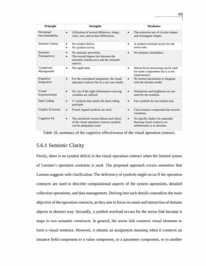
99
Principle Strengths Weakness
Perceptual
Discriminability Utilization of textual difference, shape,
color, size, and texture differences.
The extensive use of circular shapes
and rectangular shapes.
Semiotic Clarity No symbol deficit.
No symbol excess.
A symbol overload occurs for the
arrow link.
Semantic
Transparency No semantic perversity.
The overall degree lies between the
semantic translucency and the semantic
opacity.
No semantic immediacy.
Complexity
Management Not applicable. Hierarchical structuring can be used
for some components but it is not
implemented.
Cognitive
Integration For the conceptual integration, the visual
operation contract fits in a use case model.
No formal mechanism to integrate
with the domain model.
Visual
Expressiveness Six out of the eight information-carrying
variables are utilized.
Orientation and brightness are not
used for the symbols.
Dual Coding 17 symbols that satisfy the dual coding
principle.
Few symbols do not contain text.
Graphic Economy 9 basic legend symbols are used. Class instance component has several
variations.
Cognitive Fit The uncolored version (black and white)
of the visual operation contract symbols
can be adequately used.
No specific dialect for manually
drawing visual contracts on
whiteboards or as sketches.
Table 16: summary of the cognitive effectiveness of the visual operation contract.
5.6.1 Semiotic Clarity
Firstly, there is no symbol deficit in the visual operation contract when the limited syntax
of Larman’s operation contracts is used. The proposed approach covers semantics that
Larman suggests with clarification. The deficiency of symbols might occur if the operation
contracts are used to describe computational aspects of the system operations, detailed
collection operations, and data management. Delving into such details contradicts the main
objective of the operation contracts, as they aim to focus on states and interaction of domain
objects in abstract way. Secondly, a symbol overload occurs for the arrow link because it
maps to two semantic constructs. In general, the arrow link connects visual elements to
form a visual sentence. However, it obtains an assignment meaning when it connects an
instance field component to a value component, to a parameter component, or to another
100
instance field component. Thirdly, there is no symbol excess in the visual operation
contract. Each symbol carries a particular meaning in the visual contract diagram. Lastly,
the symbol redundancy does not exist in the symbols of the visual operation contract as
each semantic has only one symbol.
The visual operation contract achieves an accepted level of the semiotic even though there
is a symbol overload. We avoid introducing a special type of links because it will increase
the semiotic clarity, but will negatively affect other principles such as the perceptual
discriminability and the graph economy.
5.6.2 Perceptual Discriminability
Perceptual discriminability measures the visual distance between each two graphical
symbols; the more distance difference is the better. There are four visual variables (Figure
4) that are used to construct the visual distance between the visual elements of the visual
operation contract in addition the textual difference. These variables are shape, color, size,
and texture differences.
The visual operation contract notation has 21 shapes: 12 circular, 5 rectangular, 2 iconic
and 2 line shapes. The twelve circular shapes are the basic five circular shapes that
represent the variations of class instances plus the collection component, which can be
applied on all the basic shapes, and the deletion component, which uses two shapes. The
five rectangular shapes include the alternative component, the instance field component,
the comparison component, the value component, and the primitive parameter component.
The iconic shapes include the association formation component and the association
deletion component. The line shapes represent arrow links and undirected links.
101
The extensive use of circular shapes and rectangular shapes for the visual operation
contract has negative consequences in term of perceptually discriminability. It decreases
the visual distance and does not improve the overall perceptual discriminability. The
rationale of choosing UML entity-like shapes and rectangular shapes for most visual
elements in the visual operation contract is the unwillingness of introducing new symbols
that look completely far away from the UML notations. Our goal is to design visual
elements that are perceptually discriminable and, at the same time, to reuse and improve
the well-known notations of the UML.
Color is a visual variable that is utilized to highlight differences between the visual
components in the visual operation contract and it is used to show some similarity in some
cases. The five types of the class instance in the class instance component have different
colors. The collection component and the instance deletion component extends the shapes
of class instance components and uses their colors. The association formation and the
association deletion differ in the color and the shape. The alternative component and the
comparison component use a white background but they have borders have different colors.
The primitive parameter component, and the parameter class, variable use one color
because they both are similar in receiving operation parameters but in different forms. The
value component, the instance field component, and the link component all have unique
colors.
According to their sizes, the visual elements of the visual operation contract can be
categorized into three groups: large components, medium components, and small
components. The first group includes only the alternative component. The medium
components include the class instance components, the instance deletion component, the

102
instance field component, the value component, the parameter component, the comparison
component and the collection component. The small components include the association
formation component, the association deletion component, and the link component.
The texture in the visual operation contract is used in four components. The collection
component’s texture is the multiple circles. The instance deletion has a red circle and a red
cross. The directed link points to the target component. The primitive parameter component
has an arrow at the top-right of the rectangle.
The textual difference is used in most visual elements. Particularly, it differentiates
between instances of the same type. It applies to the class instance component, the instance
field component, the instance deletion component, the collection component, the value
component, and the parameter component. For example, each class instance component
differs from any class instance component by the instance name, which is displayed at the
bottom of its shape. The alternative component is only the component that has a text (the
abbreviation “Alt”) that does not change. The association formation component has an
optional label. It is used when there is an association format that is based on a specific
attribute. In short, the textual difference is used as the principle of perceptual
discriminability suggests; it should be the only factor that distinguishes between the
graphical symbols.
To summarize all, the visual operation contract utilizes color, size, texture, and textual
elements to draw several differences between its visual elements. The massive use of a
small group of similar shapes has a negative consequence on the overall perceptual
discriminability.
103
5.6.3 Semantic Transparency
The semantic transparency evaluates the connection between a visual component and its
semantic in a scale of four criteria (ordered from best to worst): semantic immediately,
semantic translucency, semantic opacity, and semantic perversity. So there are no visual
elements in the first criteria and none in the last criteria. There are 11 of 21 visual elements
in the visual operation contract that satisfy the semantic translucency as they indicate to
their semantic corollary in a certain way. These elements are the following components:
the primitive parameter, the association formation, the association deletion, the collection
component (five elements), the deletion instance component (2 elements), and the
alternative component. The primitive parameter symbol has an arrow indicating for an
input to the operation contract. The association formation symbol indicates a formation of
a connection between two class instances, while the association deletion symbol indicates
severing the connectivity. The multiple circles in the shape of the collection symbol
indicate the multiplicity of instances. The instance deletion component has a red cross that
refers to destruction of an instance. The alternative component has the abbreviation “Alt”.
The remaining elements satisfy the semantic opacity because novice readers infer nothing
about their semantics. The degree of the semantic transparency of the visual operation
contract lies between the semantic translucency and the semantic opacity.
5.6.4 Complexity Management
The complexity of the visual operation contract might occur due to the massive network
connection between visual components. The reduction of the diagram complexity can be
achieved by the hierarchical structuring. It seems suitable for the alternative components
104
as well as the pre-condition box, and the post-condition box. However, we do not offer any
mechanism to handle diagram complexity in the visual operation contract.
5.6.5 Cognitive Integration
The cognitive integration can be evaluated according to the conceptual integration and
perceptual integration. For the conceptual integration, the visual operation contract fits in
a use case model (Figure 23). The visual operation contract perceptually integrates with
the domain model, which is presented as a UML class diagram. The visual operation
contract uses the domain model as a source of domain objects’ instances. However, we did
not offer a formal mechanism to this integration (between the visual operation contract and
the domain model).
5.6.6 Visual Expressiveness
The degree of the visual expressiveness has a positive relationship to the number of the
information-carrying variables. The visual operation contract utilizes six out of the eight
information-carrying variables that are presented in Figure 4. These variables are the
horizontal position, the vertical position, the size, the color, the texture, and the shape. The
orientation and the brightness are two free variables that are not used in the diagram.
Therefore, the visual operation contract has a degree of six in terms of the visual
expressiveness.
5.6.7 Dual Coding
The visual operation contract has 17 symbols that satisfy the dual coding principle. These
symbols represent the class instance component (five variants), the instance field
component, the primitive parameter component, the comparison component, the value

105
component, the alternative component, the instance deletion component (two variants), and
the collection component (five variants). As they differ in at least one visual variable in
addition to the textual difference variable, these components satisfy the dual coding
principle.
5.6.8 Graphic Economy
The graphic economy assessment is based on the graphic complexity. The graphic
complexity of the visual operation contract is 9 since there are 9 basic legend symbols. The
legend symbols are:
1. The class component group: five symbols of class instance component, five
symbols of the collection component, and two symbols of the instance deletion
component.
2. The two symbols of the link component.
3. The symbol of the association formation component.
4. The symbol of the association deletion component.
5. The symbol of the instance field component.
6. The symbol of the primitive parameter.
7. The symbol of the comparison component
8. The symbol of the value component.
9. The symbol of the alternative component
According to the graphic economy principle, the graphic complexity of the visual notations
is best being around six. The graphic complexity of the visual operation contract is nine,
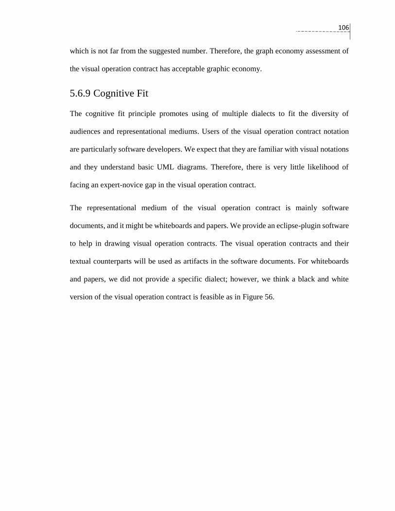
106
which is not far from the suggested number. Therefore, the graph economy assessment of
the visual operation contract has acceptable graphic economy.
5.6.9 Cognitive Fit
The cognitive fit principle promotes using of multiple dialects to fit the diversity of
audiences and representational mediums. Users of the visual operation contract notation
are particularly software developers. We expect that they are familiar with visual notations
and they understand basic UML diagrams. Therefore, there is very little likelihood of
facing an expert-novice gap in the visual operation contract.
The representational medium of the visual operation contract is mainly software
documents, and it might be whiteboards and papers. We provide an eclipse-plugin software
to help in drawing visual operation contracts. The visual operation contracts and their
textual counterparts will be used as artifacts in the software documents. For whiteboards
and papers, we did not provide a specific dialect; however, we think a black and white
version of the visual operation contract is feasible as in Figure 56.
107
Figure 56: The black and white version of the graphical symbols of the visual operation
contract.
5.7 Related Works Compared to our Visual Operation Contract
J. Cabot and C. Gómez’s approach automates a set of basic operations’ generation for the
domain classes based on their attributes and associations. The main objective of their
work is to provide automation for routine tasks, which are usually error-prone and time-
consuming. Our proposal, on the contrary, targets visualizing contracts of non-trivial
operations for the purpose of requirement analysis, and is to be used to guide object
design at later stages.
Vignaga et al.’s approach takes a step backward, limiting the use of operation contacts to
describing the data model’s state changes, and then automates the generation of objects
and associations. The operation contracts, in this approach, view the changes from a data

108
perspective, and require writing operation contracts in QVT. It is hard to tell whether this
step is necessary or not. However, this approach might be used to validate Larman’s
operation contracts.
B. Bousetta et al.’s approach extends the syntax of Larman’s operation contract to
include design choices. The extended syntax of their proposal embeds the GRASP pattern
in the post-condition, and therefore, contradicts the abstract notion of operation contracts.
The new version of operation contracts becomes, rather, design models. One criticism of
this approach is that it directly maps from declarative operation contracts to imperative
sequence diagrams. This mapping poses new challenges for the contract syntax, as it
must include implementation-specific details and pay careful attention to the order of
post-condition sentences.
The knowledge-based framework that is proposed by N. Laosen and E. Nantajeewarawa
is a practical approach in applying the GRASP patterns in a semi-automatic way. The
major drawback of this approach is the need for representing the class diagram and the
operation contact in an ontology-based language. Software engineers might not be used
to these kinds of languages. We think that our proposal can complement their approach if
we improve the transformation of the visual operation contracts to OWL.
The executable visual contract of Lohmann et al. deals with the operations in an
advanced development phase; a level matches the code level and allows the generated
contracts to fit seamlessly with the running code. In fact, the authors consider their
approach to be a visual DbC. Moreover, the executable visual contract has limited visual
expressiveness and relies heavily on text compared with the proposed visual operation
contract. For example, the visual representation of class attributes are more flexible to use

109
and more effective in the visual operation contract. In addition, the object diagrams
cannot represent some visual elements in the contract post-condition, such as alternatives
and comparisons.
The technicality and the complexity of the OCL hinder its usefulness in describing
operation contracts at early stages of software development, and this also true for visual
representations of OCL, like VOCL. The VOCL visualizes the standard OCL. The visual
notations in VOCL rely on textual OCL expressions. Therefore, software developers are
confronted with the need to learn OCL expressions. Furthermore, we target abstract
operation contracts, whereas VOCL aims to visualize a wider scope of UML constraints.
The VCL has an operation contract diagram that allows visual modelling of the operation
contracts. Then, they can be transformed to formal specifications written in the Z
language(Spivey, 1992). However, the major drawback of such proposals is that software
engineers are often reluctant to learn another modelling language that has new notations
and various diagrams.
We propose our visual operation contract to be an effective visualization approach for
Larman’s operation contracts. Contrary to the discussed visual approaches, the visual
notations target the operation contracts at early stages and respect some cognitive
effectiveness measures. In addition, we offer a transformation of the visual operation
contract to the structured textual format of Larman’s operation contracts. The syntax of
Larman’s operation contracts is improved — it is more precise and it maintains the
abstractness of the operation contact.
110
5.8 Summary of the Chapter
This chapter discusses the syntax of the proposed visual notation. The chapter motivates
the visualization process by mentioning the advantages of using Larman’s operation
contracts, the effectiveness of visual representations over their textual counterparts, and the
applicability of the visual operation contract to be part of DbC programming. Then, the
chapter introduces the necessary improvements that allow the visualization of the operation
contract. Later in this chapter, details of the visual syntax, and meta-model of the proposed
approach are introduced. Finally, the cognitive effectiveness of the visual syntax is
evaluated according to the principles of Physics of Notation theory. The visual operation
contract notation obtain an acceptable score for almost all principles, but the use of few
shapes to represent the symbols of the notation has a negative impact.

111
Chapter 6: ViOpContract Tool
This chapter introduces the prototype tool “ViOpContract” and provides a quick start
tutorial. The chapter shows the main views, menus, and explains the transformation
algorithm, which transforms a visual operation contract to a corresponding textual
representation.
6.1 Overview of the Tool
ViOpContract is a prototype tool that helps developers to draw visual operation contracts.
It is an Eclipse plug-in and can be downloaded from the link:
https://github.com/gublan24/ViOpContract. The Graphical Editing Framework (GEF)
version 3.9.0 is used to provide the means of representing the graphical elements of the
visual contracts such as components, layers, and links. The Eclipse Modeling Framework
(EMF) version 2.9.0. is used to manage the data model of ViOpContract. ViOpContract
saves the workplace data in an XMI format file ending with the “.voc” extension. The
visual editor of ViOpContract allows developers to extract the visual operation contracts
as images, zooming-in and zooming-out, and transforming visual operation contracts to the
textual counterpart.
112
The main view of ViOpContract starts with two basic window tabs, or views. The first
view helps to draw the domain model. The second view is the system operation view, which
allows developers to add system operations to a generic class and the visual operation
contracts to the system operations. Each visual operation contract has its own view. The
following sections in this chapter will describe these three views: the domain model, the
system operations, and the visual operation contract view.
6.2 Domain Model View
The domain model view shows the UML class diagram, or as the domain model diagram
of the software system. ViOpContract offers a visual editor for modeling the domain
model. For simplicity, we developed our own version of the UML class diagram that fits
our need. The metamodel of the domain model is shown in Figure 57. Domain classes can
have attributes (instance variables) and associations of different types, as the figure shows.
UMLClassDiagram acts as a container layer that contains all classes, links, and attributes.
It also includes the system class (VSystemOperationDiagram) that contains all system
operations.
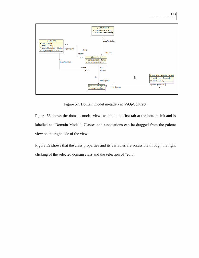
113
Figure 57: Domain model metadata in ViOpContract.
Figure 58 shows the domain model view, which is the first tab at the bottom-left and is
labelled as “Domain Model”. Classes and associations can be dragged from the palette
view on the right side of the view.
Figure 59 shows that the class properties and its variables are accessible through the right
clicking of the selected domain class and the selection of “edit”.

114
Figure 58: The domain model view of ViOpContract.
Figure 59: Edit class properties in the domain model view.
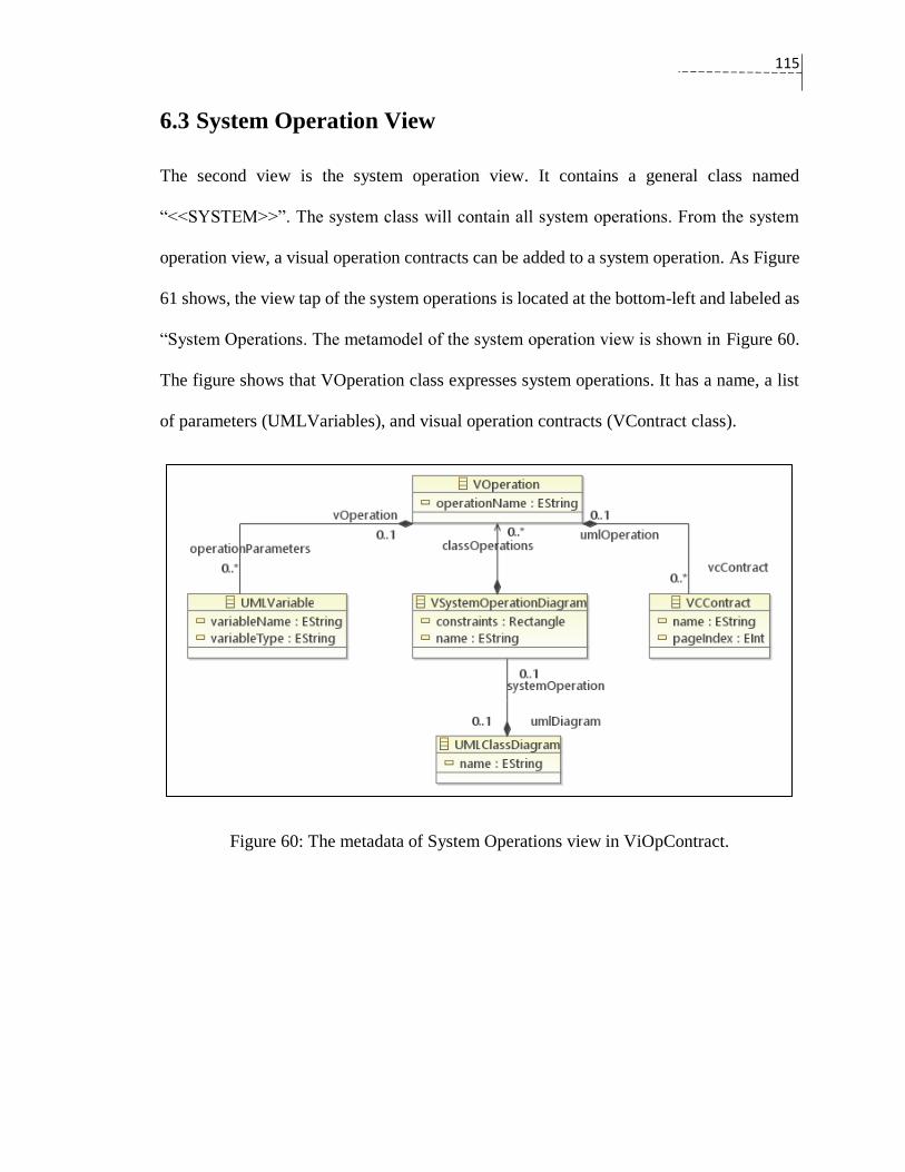
115
6.3 System Operation View
The second view is the system operation view. It contains a general class named
“<<SYSTEM>>”. The system class will contain all system operations. From the system
operation view, a visual operation contracts can be added to a system operation. As Figure
61 shows, the view tap of the system operations is located at the bottom-left and labeled as
“System Operations. The metamodel of the system operation view is shown in Figure 60.
The figure shows that VOperation class expresses system operations. It has a name, a list
of parameters (UMLVariables), and visual operation contracts (VContract class).
Figure 60: The metadata of System Operations view in ViOpContract.

116
Figure 61: System Operations in the SYSTEM class.
6.3.1 Adding System Operations
System operations can be added, deleted, and edited by using of the right click on the
<SYSTEM> class. A pop-out menu will show the list of system operations as in Figure 62.
A visual operation contract can be added to a system operation in this menu.
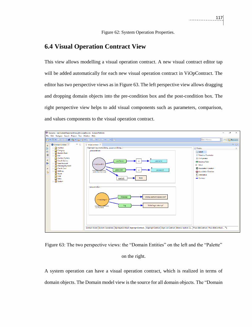
117
Figure 62: System Operation Properties.
6.4 Visual Operation Contract View
This view allows modelling a visual operation contract. A new visual contract editor tap
will be added automatically for each new visual operation contract in ViOpContract. The
editor has two perspective views as in Figure 63. The left perspective view allows dragging
and dropping domain objects into the pre-condition box and the post-condition box. The
right perspective view helps to add visual components such as parameters, comparison,
and values components to the visual operation contract.
Figure 63: The two perspective views: the “Domain Entities” on the left and the “Palette”
on the right.
A system operation can have a visual operation contract, which is realized in terms of
domain objects. The Domain model view is the source for all domain objects. The “Domain
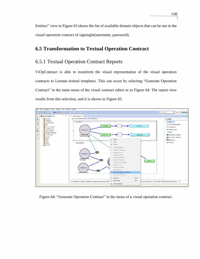
118
Entities” view in Figure 63 shows the list of available domain objects that can be use in the
visual operation contract of signingIn(username, password).
6.5 Transformation to Textual Operation Contract
6.5.1 Textual Operation Contract Reports
ViOpContract is able to transform the visual representation of the visual operation
contracts to Larman textual templates. This can occur by selecting “Generate Operation
Contract” in the main menu of the visual contract editor as in Figure 64. The report view
results from this selection, and it is shown in Figure 65.
Figure 64: “Generate Operation Contract” in the menu of a visual operation contract.
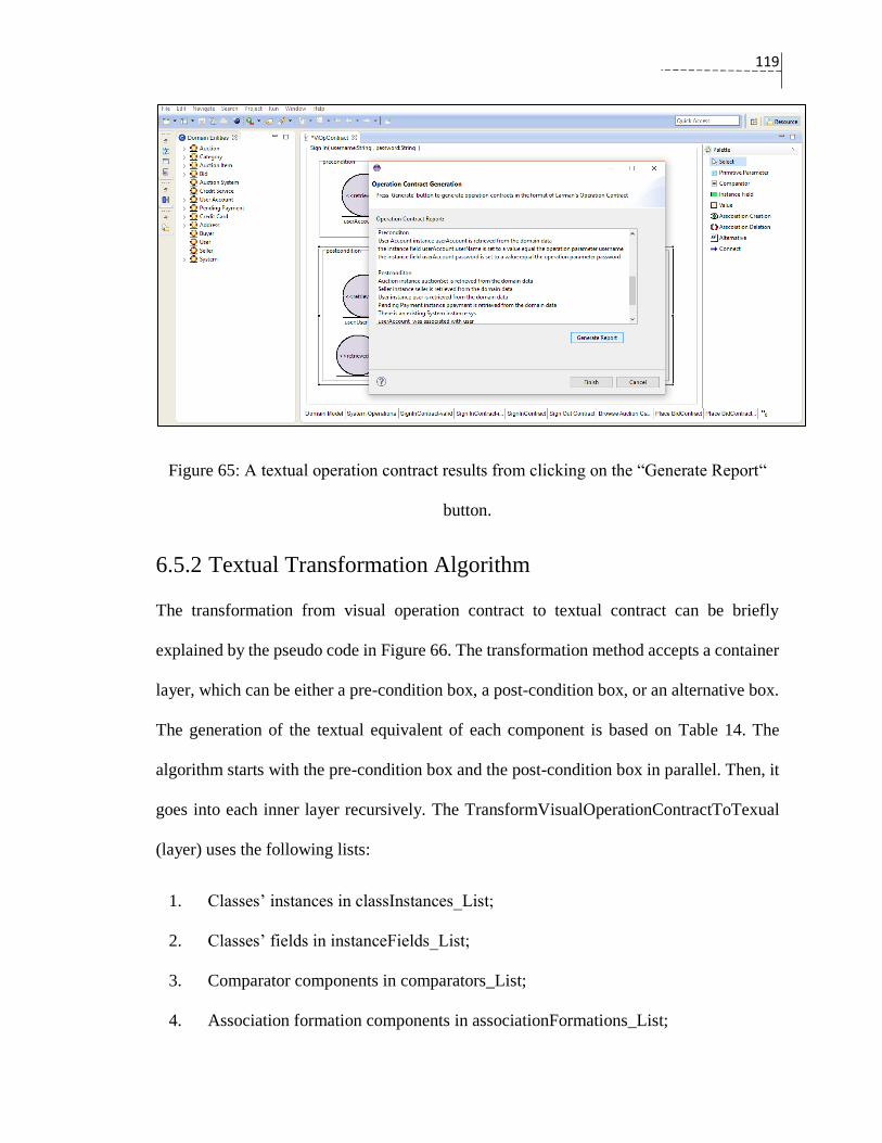
119
Figure 65: A textual operation contract results from clicking on the “Generate Report“
button.
6.5.2 Textual Transformation Algorithm
The transformation from visual operation contract to textual contract can be briefly
explained by the pseudo code in Figure 66. The transformation method accepts a container
layer, which can be either a pre-condition box, a post-condition box, or an alternative box.
The generation of the textual equivalent of each component is based on Table 14. The
algorithm starts with the pre-condition box and the post-condition box in parallel. Then, it
goes into each inner layer recursively. The TransformVisualOperationContractToTexual
(layer) uses the following lists:
1. Classes’ instances in classInstances_List;
2. Classes’ fields in instanceFields_List;
3. Comparator components in comparators_List;
4. Association formation components in associationFormations_List;
120
5. Association deletion components in associationDeletions_List; and
6. Alternatives components in alternatives_List.
As an example, the textual transformation algorithm is used to obtain the textual operation
contract from the visual operation contract of addRegisteredUser (username, password,
email, name), which is illustrated in Figure 52. The code starts with the post-condition as
a layer since the pre-condition layer is empty. For the post-condition layer, the algorithm
passes through:
1. The lines [2-3] and prints “RegisteredUser instance user is retrieved from the domain
data”
2. The lines [4-6] and prints “the instance field user.userName is set to a value equal
the operation parameter username”.
3. The lines [13 – 15] and prints “If”, and then, the algorithm will go through the
condition of the alternative as a new layer.
a. The algorithm starts from the beginning and the lines [7-8] prints
“user exist checking was false”.
4. The code resumes with the line [18] and will go through the result block of the
alternative as a layer.
a. The algorithm starts from the beginning and the lines [2-3] prints
“RegisteredUser new instance newUser was created”
b. The lines [4-6] prints “newUser.userName was assigned to a value
equals to the operation parameter username
newUser.password was assigned to a value equals to the operation
parameter password

121
newUser.email was assigned to a value equals to the operation
parameter email
newUser.username was assigned to a value equals to the operation
parameter username

122
Figure 66: The pseudo code of visual to text transformation of operation contracts.
1. TransformVisualOperationContractToTexual (layer) {
2. Iterate over a classInstances_List:
3. Print the textual interpretation of each domain instance used in the
current layer.
4. Iterate over instanceFields_List:
5. If(instanceField is assigned to a value )
6. Print the textual interpretation of the assignment.
7. Iterate over comparators_List:
8. Print textual interpretation of the source component, the comparator, the
target component of the current comparator.
9. Iterate over associationFormations_List:
10. Print textual interpretation of the source component, the association, the
target component of the current association formation.
11. Iterate over associationDeletions_List:
12. Print textual interpretation of the source component, the association, the
target component of the current association deletion.
13. Iterate over alternatives_List:
14. Iterate over conditionOptions:
15. Print “If”+ TrasformVisualOperationContractToTexual
(conditonBlockLayer)
16. Print TransformVisualOperationContractToTexual (resultBlockLayer)}
17. Iterate over a classInstances_List:
18. Print the textual interpretation of each domain instance that is indicated
as deleted instance.
123
Chapter 7: Case Study
In this chapter, the AuctionSystem is used as a case study. The prototype tool
ViOpContract will be used to draw visual operation contracts for representative system
operations. The use-case model of the AuctionSystem was provided in Figure 18 .We will
focus on three use-cases: Sign In, Create Account, and Browse. Each use-case will be
discussed in the following manner:
1. A description of the use-case will be provided.
2. A system sequence diagram will be generated from the use-case text by following
Larman’s convention (Larman, 2005, sec 10.2).
3. The ViOpContract will be used to draw a visual operation contract for the system
sequence diagram.
4. A textual equivalent of the visual operation contract will be presented.
7.1 Sign In Use-Case
Figure 67 shows a textual description for Sign In use-case. This use-case illustrates the
functionality of the login in the auction system.
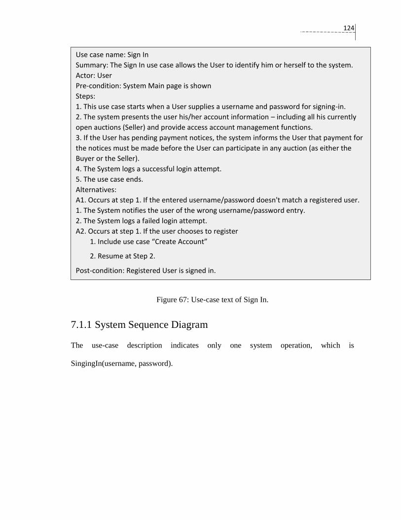
124
Figure 67: Use-case text of Sign In.
7.1.1 System Sequence Diagram
The use-case description indicates only one system operation, which is
SingingIn(username, password).
Use case name: Sign In
Summary: The Sign In use case allows the User to identify him or herself to the system.
Actor: User
Pre-condition: System Main page is shown
Steps:
1. This use case starts when a User supplies a username and password for signing-in.
2. The system presents the user his/her account information – including all his currently
open auctions (Seller) and provide access account management functions.
3. If the User has pending payment notices, the system informs the User that payment for
the notices must be made before the User can participate in any auction (as either the
Buyer or the Seller).
4. The System logs a successful login attempt.
5. The use case ends.
Alternatives:
A1. Occurs at step 1. If the entered username/password doesn't match a registered user.
1. The System notifies the user of the wrong username/password entry.
2. The System logs a failed login attempt.
A2. Occurs at step 1. If the user chooses to register
1. Include use case “Create Account”
2. Resume at Step 2.
Post-condition: Registered User is signed in.

125
Figure 68: SiginingIn system sequence diagram.
7.1.2 SigningIn Visual Operation Contract
There are two ways to implement the visual operation contract for SigningIn operation.
The first way uses a visual operation contract per a scenario. Therefore, we need two visual
operation contracts (as in Figure 69 and Figure 70): one for a valid-user scenario, and
another for an invalid-user scenario. The second way is using only one visual operation
contract as Figure 71 shows.
Although the two-scenario representation seems more illustrative and easy to navigate
through, the one-scenario representation, which includes the two variations of the signingIn
operation in one visual contract, is more accurate to describe the signingIn operation.
According to Meyer, “a pre-condition applies to all calls of the routine” (Meyer, 1997, p.
340). Description an operation using separate contracts as above, contradicts this notion,
as each contract separately is not a complete description of the operation. Hence, the
splitting of the contract contradicts with the definition of the pre-condition.
A. Valid SigningIn Visual Operation Contract

126
Figure 69: The visual operation contract of siginingIn system operation for a valid user.
Invalid SigningIn Visual Operation Contract
Figure 70: The visual operation contract of siginingIn system operation for an invalid
user.
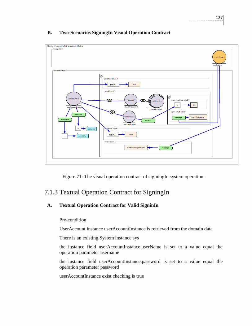
127
B. Two-Scenarios SigningIn Visual Operation Contract
Figure 71: The visual operation contract of siginingIn system operation.
7.1.3 Textual Operation Contract for SigningIn
A. Textual Operation Contract for Valid SigninIn
Pre-condition
UserAccount instance userAccountInstance is retrieved from the domain data
There is an existing System instance sys
the instance field userAccountInstance.userName is set to a value equal the
operation parameter username
the instance field userAccountInstance.password is set to a value equal the
operation parameter password
userAccountInstance exist checking is true

128
Post-condition
Bid collection instance bidInstance is retrieved from the domain data
PendingPayment instance paymentInstance is retrieved from the domain data
userAccountInstance was associated with paymentInstance
userAccountInstance was associated with bidInstance
If ( the instance field paymentInstance.amount was set to a value greater than 0 )
sys.message was assigned to a value equals to "unpaid payment"
B. Textual Operation Contract for Invalid SigningIn
Pre-condition
UserAccount instance user is retrieved from the domain data
There is an existing System instance sys
the instance field user.userName is set to a value equal the operation parameter
username
the instance field user.password is set to a value equal the operation parameter
password
user exist checking is false
Post-condition
sys.message was assigned to a value equals to "wrong username/password"
C. Textual operation contract for Two-Scenarios SigningIn
Pre-condition
There is an existing System instance sys
Post-condition
UserAccount instance userAccountInstance is retrieved from the domain data
the instance field userAccountInstance.userName was set to a value equal the
operation parameter username
the instance field userAccountInstance.password was set to a value equal the
operation parameter password
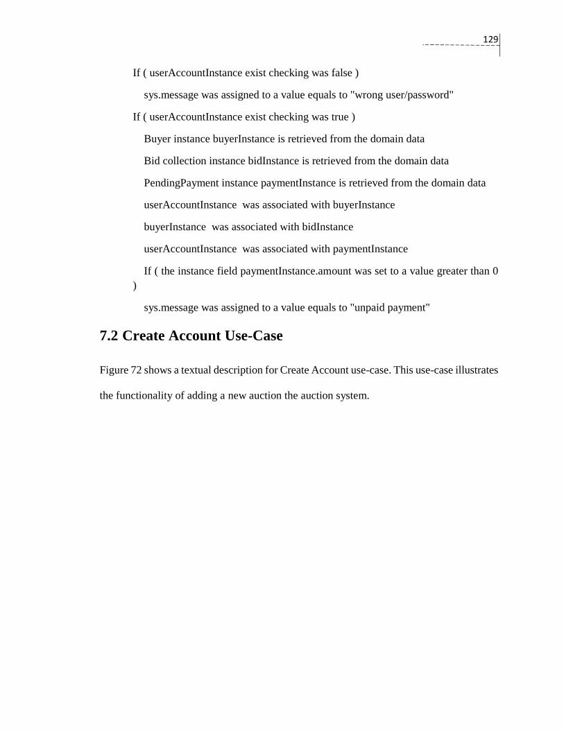
129
If ( userAccountInstance exist checking was false )
sys.message was assigned to a value equals to "wrong user/password"
If ( userAccountInstance exist checking was true )
Buyer instance buyerInstance is retrieved from the domain data
Bid collection instance bidInstance is retrieved from the domain data
PendingPayment instance paymentInstance is retrieved from the domain data
userAccountInstance was associated with buyerInstance
buyerInstance was associated with bidInstance
userAccountInstance was associated with paymentInstance
If ( the instance field paymentInstance.amount was set to a value greater than 0
)
sys.message was assigned to a value equals to "unpaid payment"
7.2 Create Account Use-Case
Figure 72 shows a textual description for Create Account use-case. This use-case illustrates
the functionality of adding a new auction the auction system.
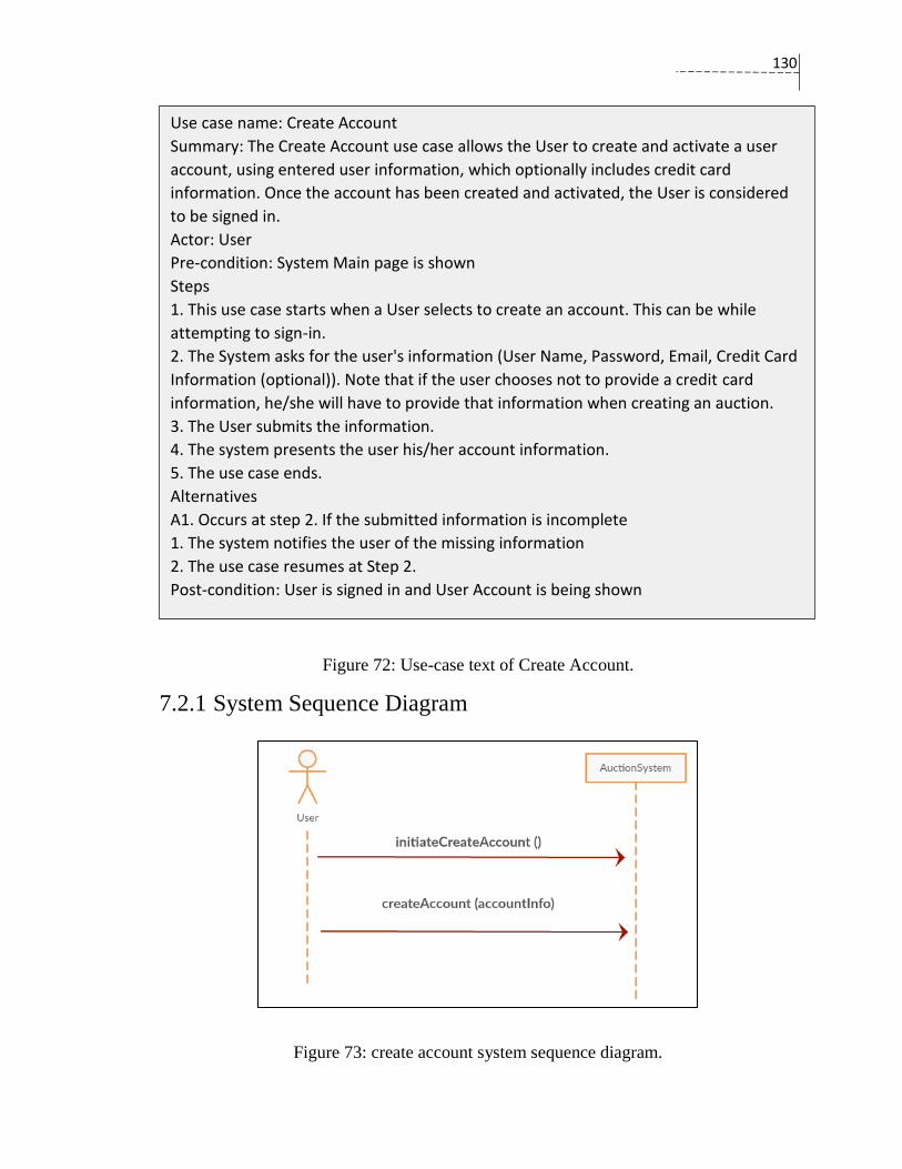
130
Figure 72: Use-case text of Create Account.
7.2.1 System Sequence Diagram
Figure 73: create account system sequence diagram.
Use case name: Create Account
Summary: The Create Account use case allows the User to create and activate a user
account, using entered user information, which optionally includes credit card
information. Once the account has been created and activated, the User is considered
to be signed in.
Actor: User
Pre-condition: System Main page is shown
Steps
1. This use case starts when a User selects to create an account. This can be while
attempting to sign-in.
2. The System asks for the user's information (User Name, Password, Email, Credit Card
Information (optional)). Note that if the user chooses not to provide a credit card
information, he/she will have to provide that information when creating an auction.
3. The User submits the information.
4. The system presents the user his/her account information.
5. The use case ends.
Alternatives
A1. Occurs at step 2. If the submitted information is incomplete
1. The system notifies the user of the missing information
2. The use case resumes at Step 2.
Post-condition: User is signed in and User Account is being shown
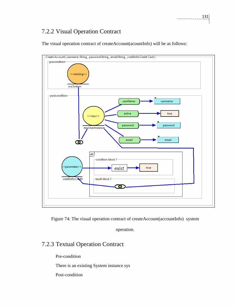
131
7.2.2 Visual Operation Contract
The visual operation contract of createAccount(acountInfo) will be as follows:
Figure 74: The visual operation contract of createAccount(accountInfo) system
operation.
7.2.3 Textual Operation Contract
Pre-condition
There is an existing System instance sys
Post-condition
132
UserAccount new instance newUserInstance was created
CreditCard instance creditInfo was received from the operation parameters
newUserInstance.userName was assigned to a value equals to the operation
parameter username
newUserInstance.active was assigned to a value equals to true
newUserInstance.password was assigned to a value equals to the operation
parameter password
newUserInstance.email was assigned to a value equals to the operation parameter
sys was associated with newUserInstance
If ( creditInfo existance checking was true )
newUserInstance was associated with creditInfo
7.3 Browse Catalog Use-Case
Figure 75 shows a textual description for Browse Auction Catalog use-case. This use-case
illustrates the functionality of browsing auctions in the auction system.

133
Figure 75: Use-case text of Browse Auction Catalog
7.3.1 System Sequence Diagram
Figure 76: The visual operation contract of browseAuction(searchCriteria) system
operation.
Use case name: Browse Auction Catalog
Summary: The Browse Auction Catalog use case allows the User to browse items
currently available for auction. The User may search for a specific item, or look at all of
the items currently available for auction, sorted by category.
The User has the option to place a bid on an item available for auction.
The User does not have to be signed in to browse the auction catalog.
Actor: User
Pre-condition: System Main page is shown
Steps
1. This use case starts when a User specifies a search criteria (specific item, category)
2. The System displays all current auctions matching the search criteria.
3. The use case ends.
Alternatives
A1. Occurs at Step 2. If there is no auction matching the search criteria
1. The System notifies that no auction was found.
Post-condition: Auctions are being displayed
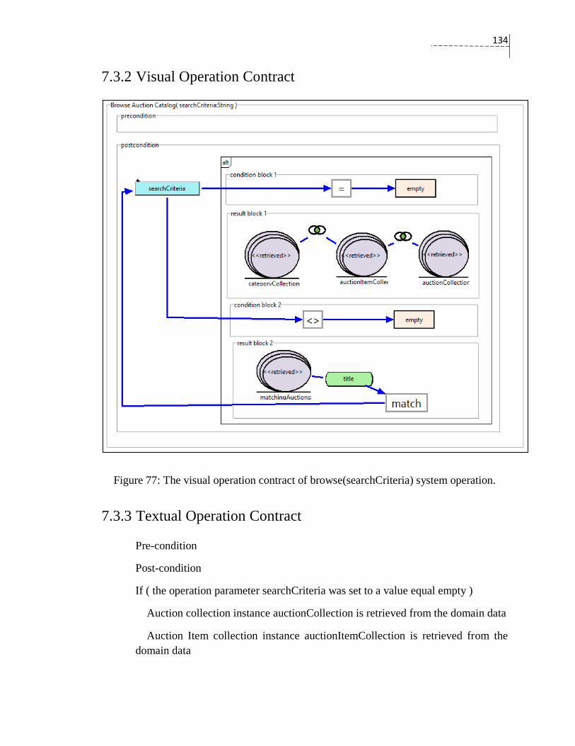
134
7.3.2 Visual Operation Contract
Figure 77: The visual operation contract of browse(searchCriteria) system operation.
7.3.3 Textual Operation Contract
Pre-condition
Post-condition
If ( the operation parameter searchCriteria was set to a value equal empty )
Auction collection instance auctionCollection is retrieved from the domain data
Auction Item collection instance auctionItemCollection is retrieved from the
domain data
135
Category collection instance categoryCollection is retrieved from the domain
data
auctionCollection was associated with auctionItemCollection
auctionItemCollection was associated with categoryCollection
If ( the operation parameter searchCriteria was set to a value not equal empty )
Auction Item collection instance matchingAuctions is retrieved from the domain
data
the instance field matchingAuctions.title was set to a value match the operation
parameter searchCriteria
7.4 Summary of the Chapter
The chapter uses three use-cases to shows how ViOpContract can be used to facilitate the
drawing, and the generation of corresponding textual representation for the visual operation
contracts. The aim of this chapter is not to cover all the use-cases of the AuctionSystems,
but to use these use-cases as representative samples of the case study.
136
Chapter 8: Conclusion
8.1 Summary of the Contributions
In this thesis, we proposed a visual notation for Larman’s operation contracts. The
effectiveness of the visual representation of the visual operation contract is guided by the
Physics of Notations theory, which is used as a cognitive effectiveness benchmark for
evaluating visual syntaxes of software visual models. The visual elements of the visual
operation contract can be grouped into two main categories: reused UML notations, and
new notations. The first category includes UML notations that are used in the visual
operation contact. The elements in this category are slightly modified to obtain better
cognitive effectiveness. The second group include notations that do not have UML origins,
but they fit with the general theme of the UML. We introduced a new element only when
there is no available notation for the corresponding semantic in UML.
To achieve the goal of offering a visual syntax for Larman’s operation contracts, the syntax
of the operation contracts require some clarification and formalization. We extended the
operation contracts’ syntax with a few keywords that improves the accuracy of the creation
statement and clarifies the relationship between domain objects and their data.
Furthermore, the improved syntax offers structured constructs that express data constraints,

137
and system operations’ alternatives in addition to the main role of the operation contracts
of describing the creation/deletion of domain objects and their associations.
There are three main keywords added to the creation statement of Larman’s operation
contracts. The keywords aim to distinguish between the following:
1. Temporary domain objects;
2. New domain objects; and
3. Retrieved domain objects.
The new, temporary, and retrieved are three types of domain objects. They point to data
aspects of domain objects in the operation contacts. Domain objects’ data may last for
different periods. According to the specifications of a system operation, data might be
created temporarily as in the first type. It lasts for a short span, and it will be disposed after
the operation execution. In the second type, the data of the domain objects is stored
permanently in a data repository after performing the operation. In the third type, the data
of a domain object was received from a data repository and the domain object was used in
the operation contract. Software system operations are often composed of instances of these
types; however, Larman’s operation contract did not clearly distinguish between them. Our
approach clarifies these differences and avoids software developers using different ways
to describe the data aspects of domain objects in the operation contracts.
We offered an Eclipse plug-in prototype tool (ViOpContract). It implements the proposed
visual operation contract, and can be used to assist its practicality. The tool helps software
developers to draw, and to manage visual operation contracts. The tool has the capability
138
to transform from visual operation contracts to textual format of Larman’s operation
contacts.
8.2 Limitations
We reused some available UML notations, and introduced new notations with the condition
of not conflicting with the general theme of the UML. These two factors limit the selection
of shapes to a small range of variations. These shapes are used as symbols for the visual
elements in the proposed approach. For instance, we avoided using parallelograms,
octagons, and stars for the visual elements because they do not fit-well with the general
theme of the UML notations. Therefore, the use of a limited number of shapes has negative
implications on some aspects of the cognitive effectiveness; however, there is enormous
popularity of UML notations among software developers. The popularity of UML leads us
to think of reusing UML notations instead of designing a complete set of visual symbols
for the proposed approach. The reuse of UML notations is a considerable gain that will
increase the understanding, and the adaptation of the visual operation contract.
Although some of the components can be customized to several contexts, the visual
operation contract has a limited semantic scope compared with the non-formalized textual
operation contracts. In some cases, the outcome of a system operation might depend on
arithmetic computations, or data processing. These kind of operations are not addressed in
the operation contracts. However, the textual and informal description of Larman’s
contracts offers unlimited scope. To some extent, extending our approach to cover extra
semantics such as numerical operations, navigation of domain objects, and so on, is not a
hard task; but the goal of the visual operation contract is in line with Larman’s contracts

139
goal. It is the highlighting of changes in domain objects without delving into detailed
specifications of the system operations. We think that the capability of the visual operation
contract is sufficient for system operations’ cases, and it maintains the abstractness of the
system operations as an early software artifact.
Use-case centric approaches are useful to describe interactive software systems; however,
they have shortcomings to describe certain types of software systems. Particularly,
software systems that embody complex business rules, large-scale data management, real-
time operations, and time-triggered functions (Wiegers, 2005). The visual operation
contract inherits such limitations because they are based on a use-case centric approach.
For examples, the operation contracts (both textual and visual representation) fail to
describe real-time operations in which the data of domain objects is rapidly changing; there
is no one final state that can be a post-condition of the operation.
The cognitive effectiveness and the usefulness of the proposed approach require unbiased
and reliable experimental evaluations. The software experimental assessments are crucial
to evaluate new methods, techniques, and artifacts (Wohlin, Runeson, Host, & Ohlsson,
2012). Our approach has not been evaluated according to experiments and empirical studies
yet, the time limitation of the thesis is the major obstacle that hinders us from doing such
activities.
8.3 Future Work
Wohin et al. advised software researchers to go beyond academic assessments to
substantiate academic hypothesis about new software methods and tools; empirical studies
should be undertaken as well (Wohlin et al., 2012). We agree with Wohin et al, and we

140
want to conduct an empirical study to examine the overall effectiveness of the visual
operation contract that will include the practical usefulness and the cognitive efficiency.
The literature review of this thesis shows several approaches that are proposed to automate
the extraction of the object interaction and the sequence diagrams from the operation
contracts based on the GRASP patterns. Most of these approaches enforce using specific
representations of the operation contracts such as OWL, and QVT. The adaptation of these
approaches is hindered by the required specific representations. As the visual operation
contract captures the operation contracts in a graphical formal model, it provides a base
from which we can extend the model transformation of the operation contracts to support
different specifications.
The current version of the prototype tool (ViOpContract) offers a transformation capability
to the textual form of Larman operation contacts. The tool can be enhanced further by
enabling simultaneous visual-textual representation of the operation contact. In case of
semantics that do not have representation in the visual operation contract, one solution
would be expressing these semantics in a textual notation. Another alternative would be
providing a framework that has the capability to incorporate new and customized
components that allow software developers to tailor them to fit their specific domains.
141
Bibliography
Abdelzad, V., Amyot, D., Alwidian, S. A., & Lethbridge, T. C. (2015). A textual syntax
with tool support for the goal-oriented requirement language. Presented at the Proceedings
of the Eighth International i*Workshop - iStar 2015, Ottawa, Canada.
Amálio, N., & Kelsen, P. (2010). Modular design by contract visually and formally using
VCL. Presented at the 2010 IEEE Symposium on Visual Languages and Human-Centric
Computing, Leganes, Spain.
Arnold, D., Corriveau, J. P., & Shi, W. (2010). Modeling and validating requirements using
executable contracts and scenarios. In 2010 Eighth ACIS International Conference on
Software Engineering Research, Management and Applications (pp. 311–320). Montreal,
QC, Canada: IEEE.
Bertin, J. (1983). Semiology of graphics: diagrams, networks, maps. Madison, WI: the
University of Wisconsin Press, Ltd.
Bousetta, B., Omar, E., & Gadi, T. (2013). Automating software development process:
Analysis-PIMs to Design-PIM model transformation. International Journal of Software
Engineering and Its Application, 7, 167–196.
Brambilla, M., Cabot, J., & Wimmer, M. (2012). Model-driven software engineering in
practice. Synthesis Lectures on Software Engineering, 1(1), 1–182.
doi:10.2200/s00441ed1v01y201208swe001
142
Briand, L., Labiche, Y., & Madrazo-Rivera, R. (2011). An experimental evaluation of the
impact of system sequence diagrams and system operation contracts on the quality of the
domain model. In 2011 International Symposium on Empirical Software Engineering and
Measurement (pp. 157–166). doi:10.1109/ESEM.2011.24
Cabot, J., & Gómez, C. (2007). Deriving operation contracts from UML class diagrams. In
Model Driven Engineering Languages and Systems (pp. 196.–210). Springer Berlin
Heidelberg.
Cheng, P., Lowe, R. K., & Scaife, M. (2001). Cognitive science approaches to
understanding diagrammatic representations. Artificial Intelligence Review, 15(1-2), 79–
94.
Eeles, P., Houston, K., & Kozaczynski, W. (2002). Building J2EE applications with the
rational unified process. Boston: Addison-Wesley Longman Publishing Co., Inc.
Ehrig, K., & Winkelmann, J. (2006). Model transformation from VisualOCL to OCL using
graph transformation. Electronic Notes in Theoretical Computer Science, 152, 23–37.
doi:http://dx.doi.org/10.1016/j.entcs.2006.01.012
Estler, H. C., Furia, C. A., Nordio, M., & Piccioni, M. (2014). Contracts in practice. In FM
2014: Formal Methods (pp. 230–246). Springer International Publishing. doi:10.1007/978-
3-319-06410-9_17
Evans, E. (2003). Domain-driven design: tackling complexity in the heart of software (pp.
35–37). Addison-Wesley Professional.

143
Genon, N., Amyot, D., & Heymans, P. (2011). Analysing the Cognitive Effectiveness of
the UCM Visual Notation. In System Analysis and Modeling: About Models (pp. 221–
240). Berlin, Heidelberg: Springer Berlin Heidelberg. doi:10.1007/978-3-642-21652-7_14
Goolkasian, P. (2000). Pictures, words, and sounds: From which format are we best able
to reason? The Journal of General Psychology, 127(4), 439––459.
Grönninger, H., Krahn, H., Rumpe, B., & Schindler, M. (2014). Textbased modeling. In
Proceedings of the 4th International Workshop on Software Language Engineering (ateM
2007).
Heckel, R., & Lohmann, M. (2007). Model-driven development of reactive information
systems: from graph transformation rules to JML contracts. International Journal on
Software Tools for Technology Transfer, 9(2), 193–207.
Hoare, C. A. R. (1969). An axiomatic basis for computer programming. Communications
of the ACM, 12(10), 576–580.
Jacobson, I., Booch, G., Rumbaugh, J., Rumbaugh, J., & Booch, G. (1999). The unified
software development process (Vol. 1). Reading: Addison-Wesley.
Jacobson, I., Spence, I., & Bittner, K. (2011). Use Case 2.0: The guide to succeeding with
use cases. Ivar Jacobson International, 49. –50.
Kiesner, C., Taentzer, G., & Winkelmann, J. (2002). Visual OCL: a visual notation of the
object constraint language (p. 29). Technical Report 23, Computer Science Department of
the Technical University of Berlin, Germany.
144
Kruchten, P. (2000). The rational unified process: An introduction (2nd ed.). Boston, MA,
USA: Addison-Wesley Longman Publishing Co., Inc.
Laosen, N., & Nantajeewarawat, E. (2015). A knowledge-based approach for generating
UML sequence diagrams from operation contracts (pp. 388–399). Presented at the Tenth
International Conference on Knowledge, Information and Creativity Support Systems,
Phuket, Thailand.
Larkin, J. H., & Simon, H. A. (1987). Why a diagram is (sometimes) worth ten thousand
words. Cognitive Science, 11(1), 65–100.
Larman, C. (2005). Applying UML and patterns: an introduction to object-oriented
analysis and design and iterative development (3rd ed.). Upper Saddle River, N.J: Prentice
Hall PTR.
Lethbridge, T., & Laganiere, R. (2001). Object-oriented software engineering: practical
software engineering using UML and Java (2nd ed.). Mcgraw-Hill College.
Lohmann, M., Engels, G., & Sauer, S. (2006). Model-driven monitoring: Generating
assertions from visual contracts. In 21st IEEE/ACM International Conference on
Automated Software Engineering ASE'06 (pp. 355–356). IEEE.
Lohmann, M., Sauer, S., & Engels, G. (2005). Executable visual contracts. In 2005 IEEE
Symposium on Visual Languages and Human-Centric Computing (VL/HCC'05) (pp. 63–
70). IEEE.
Meyer, B. (1997). Object-oriented software construction (Vol. 2). Prentice Hall.
145
Meyer, B. (2000). Towards more expressive contracts. Journal of Object Oriented
Programming, 13(4), 39–43.
Miller, G. A. (1956). The magical number seven, plus or minus two: some limits on our
capacity for processing information. Psychological Review, 63(2), 81–97.
Moody, D. L. (2009). The “physics” of notations: toward a scientific basis for constructing
visual notations in software engineering. IEEE Transactions on Software Engineering, 35,
756–779.
Moody, D. L., Heymans, P., & Matulevičius, R. (2010). Visual syntax does matter:
improving the cognitive effectiveness of the i* visual notation. Requirements Engineering,
15(2), 141–175.
Moody, D., & Hillegersberg, J. (2009). Evaluating the visual syntax of UML: an analysis
of the cognitive effectiveness of the UML family of diagrams. In Software Language
Engineering (pp. 16–34). Berlin, Heidelberg: Springer Berlin Heidelberg.
doi:10.1007/978-3-642-00434-6_3
Nebut, C., Fleurey, F., Traon, Y. L., & Jézéquel, J.-M. (2003). Requirements by contracts
allow automated system testing (pp. 85–96). Presented at the 14th International
Symposium on Software Reliability Engineering, 2003. ISSRE 2003.
Paivio, A. (1990). Mental representations: a dual coding approach. Oxford University
Press.

146
Pohl, K., & Rupp, C. (2015). Requirements engineering fundamentals: a study guide for
the certified professional for requirements engineering exam - foundation level - IREB
compliant (2nd ed., pp. 60–62). Santa Barbara, CA: Rocky Nook.
Purchase, H. C., Carrington, D., & Allder, J. A. (2002). Empirical evaluation of aesthetics-
based graph layout. Empirical Software Engineering, 7(3), 233–255.
doi:10.1023/A:1016344215610.
Shaft, T. M., & Vessey, I. (2006). The role of cognitive fit in the relationship between
software comprehension and modification. Mis Quarterly, 29–55.
Shakya, B & Nantajeewarawat, E. (2013). A design pattern knowledge base and its
application to sequence diagram design. 2013 International Computer Science and
Engineering Conference ICSEC (pp. 179-184). Nakorn Pathom, Bangkok, Thailand
doi: 10.1109/ICSEC.2013.6694775.
Spivey, J. M. (1992). The Z notation: a reference manual. International Series in Computer
Science. Prentice-Hall, New York, NY.
Standard, E. S. S. (1996). EBNF: iso/iec 14977: 1996 (e). URL
https://www.cl.cam.ac.uk/~mgk25/iso-14977.pdf, 70.
Taentzer, G., Parisi-Presicce, F., Koch, M., & Bottoni, P. (2001). A Visualization of OCL
Using Collaborations. In ≪ UML≫ 2001— The Unified Modeling Language (pp. 257–
271). Springer Berlin Heidelberg. doi:10.1007/3-540-45441-1_20
Vignaga, A., Perovich, D., & Bastarrica, M. C. (2008). On Extracting a Design out of
Software Contracts using Model Transformations. Theory and Practice of Model
147
Transformations: First International Conference, ICMT 2008, Zürich, Switzerland, July 1-
2, 2008 Proceedings (pp. 245–259). Berlin, Heidelberg: Springer Berlin Heidelberg.
Warmer, J., & Kleppe, A. (1999). OCL: the constraint language of the UML. Journal of
Object-Oriented Programming, 12(1), 10–13.
Wiegers, K. (2005). More about software requirements: Thorny issues and practical advice
(pp. 90–91). Microsoft Press.
Wieringa, R. (1998). A survey of structured and object-oriented software specification
methods and techniques. ACM Computing Surveys (CSUR), 30(4), 459–527.
Wieringa, R. J. (2014). Design science methodology for information systems and
software engineering. Springer.
Wirfs-Brock, R., Wilkerson, B., & Wiener, L. (1990). Designing object-oriented software.
Englewood Cliffs, N.J: Prentice Hall.
Wohlin, C., Runeson, P., Host, M., & Ohlsson, M. C. (2012). Experimentation in software
engineering (pp. 5–8). Springer Berlin Heidelberg. doi:10.1007/978-3-642-29044-2