a visual editor for semantics specifications using the ... · a visual editor for semantics...
TRANSCRIPT

A Visual Editor for Semantics SpecificationsUsing the Eclipse Graphical Modeling
Framework
Bachelor Thesis
Malte Rohs
University of Paderborn


Contents
List of Figures v
1 Introduction 1
2 Fundamentals 32.1 Dynamic Meta Modeling . . . . . . . . . . . . . . . . . . . . . 32.2 Eclipse . . . . . . . . . . . . . . . . . . . . . . . . . . . . . . . 6
2.2.1 Eclipse Modeling Framework . . . . . . . . . . . . . . . 92.2.2 Graphical Editing Framework . . . . . . . . . . . . . . 122.2.3 Graphical Modeling Framework . . . . . . . . . . . . . 13
3 Implementation 173.1 Requirements . . . . . . . . . . . . . . . . . . . . . . . . . . . 17
3.1.1 Ruleset Editor . . . . . . . . . . . . . . . . . . . . . . . 183.1.2 Rule Editor . . . . . . . . . . . . . . . . . . . . . . . . 19
3.2 Realization . . . . . . . . . . . . . . . . . . . . . . . . . . . . 203.2.1 GMF Models . . . . . . . . . . . . . . . . . . . . . . . 213.2.2 Constraints . . . . . . . . . . . . . . . . . . . . . . . . 263.2.3 Diagram Partitioning . . . . . . . . . . . . . . . . . . . 273.2.4 Abstract Rule Problem . . . . . . . . . . . . . . . . . . 283.2.5 Customized Code . . . . . . . . . . . . . . . . . . . . . 29
3.3 Open GMF Problems . . . . . . . . . . . . . . . . . . . . . . . 36
4 Conclusion 394.1 Outlook . . . . . . . . . . . . . . . . . . . . . . . . . . . . . . 40
A List of Acronyms 43
iii

iv CONTENTS
References 45

List of Figures
2.1 Class diagram of the abstract syntax of DMM . . . . . . . . . 52.2 An example DMM rule . . . . . . . . . . . . . . . . . . . . . . 62.3 Overview of the Eclipse architecture . . . . . . . . . . . . . . . 82.4 The four layers defined by MOF . . . . . . . . . . . . . . . . . 102.5 GEF communication chain . . . . . . . . . . . . . . . . . . . . 142.6 Correlation between .ecore, .gmfgraph and .gmfmap . . . . . . 152.7 The EMF and GMF models and their relations . . . . . . . . 16
3.1 Correlation of the GMF models of the DMM editor . . . . . . 223.2 Correlation between ruleset files .gmfmap, .gmftool, .gmfgraph
and .ecore . . . . . . . . . . . . . . . . . . . . . . . . . . . . . 253.3 GMF models of the DMM editor after solving the abstract
Rule problem . . . . . . . . . . . . . . . . . . . . . . . . . . . 293.4 Ruleset editor without customized code . . . . . . . . . . . . . 303.5 Rule editor without customized code . . . . . . . . . . . . . . 313.6 Ruleset editor with customized code . . . . . . . . . . . . . . . 323.7 Rule editor with customized code . . . . . . . . . . . . . . . . 33
4.1 Screenshot of our DMM Editor . . . . . . . . . . . . . . . . . 40
v

Chapter 1
Introduction
Model Driven Development (MDD) founds on the idea of generating modelsof the desired software instead of directly writing program code. From thesemodels the code for the specified software can be automatically generated byusing generators. Changes in the software are applied on the model and thecode will just be re-generated. So in the best case, the developer does nothave to write a single line of code.
This leads to several advantages: Now people who are involved in the de-velopment process but are not familiar with programming (like future usersor specialized staff from the application range of the software) can more eas-ily understand and influence the development process because models arean intuitive presentation. By using different generators to generate the codefrom the models the software can easily be translated to different platformsand the developer does not need to have a detailed knowledge of the usedtarget programming language. As mentioned before, changes only need tobe applied on the model. But the most crucial benefit probably is that thecode does not have to be written by hand. Most software projects need basicfunctionalities like graphical user interfaces and data management functionswhich can mainly be generated automatically. Another point is that gen-erated code normally has a good quality, because the same code is used bya high number of developers and errors are quickly detected, reported andcorrected.
To employ a model driven approach, the semantic of the model needsto be unambiguously specified. This unambiguousness is necessary to avoiddifferent interpretations of the semantic meanings of model elements. Thesemantic of a model can be split into the structure (the static semantic) andthe behavior (the dynamic semantic). The description of the static semanticof a model can be done with meta models (using e.g. class diagrams). But
1

2 Chapter 1. Introduction
for the description of the dynamic semantic there is no standard technique.The need for a precise and easily understandable technique for a dy-
namic semantic description has led to the development of the Dynamic MetaModeling (DMM) technique, which was introduced in [EHHS00]. DMM de-scribes the behavior of a model in a visual way.
This leads to the topic of this bachelor thesis: the model driven develop-ment of a visual editor for DMM using Eclipse.
A requirement for the editor is that it shall be implemented as a richgraphical editor via an Eclipse plug-in. One reason is, that the editor will bepart of a bigger chain which is also implemented as Eclipse plug-ins. Thischain leads from DMM to a Groove ([Ren04]) model. The idea is to visuallycreate a DMM ruleset which can be transformed into a Groove model (see[Sto08]) and then be used as input for model checking tools. Another reasonfor using Eclipse is that a rich graphical editor provides a lot of basic needs asmenus or toolbars and benefits like zooming functions. Also Eclipse is a opensource software which makes it in general interesting for research projects.
Furthermore this thesis points out, up to which point a visual editor canbe developed purely model driven (using Eclipse) and for which functionali-ties customized code is needed. In the case that we have to write customizedcode we want to separate the generated from the customized code to avoidinterferences between re-generated and hand written code.
This thesis is structured as follows: Chapter 2 will explain the basic foun-dations needed to understand the development of the DMM editor and thedecisions which were made. It starts with an introduction to DMM. After-wards the Eclipse architecture is explained. The rest of chapter 2 considersthe used Eclipse projects EMF, GEF and GMF. Chapter 3 describes theimplementation of the editor. Therefore it first defines the requirements forthe editor and then covers the realization by considering the different modelsand the customized code. Chapter 4 contains the conclusion of this thesisalogn with remarks on possible future works on the editor.
Chapter 2
Fundamentals
This chapter discusses the fundamentals needed to understand the construc-tion of the editor and the decisions that were made. First it describes thebasic idea of DMM and shows up a short example. Then Eclipse will bedescribed, starting with a few words about the Eclipse Foundation and thenexamining the architecture of Eclipse. After the introduction of Eclipse, thefor this work important Eclipse projects, the Eclipse Modeling Framework(EMF), the Graphical Editing Framework (GEF) and the Graphical Mod-eling Framework (GMF), are presented. Reader who are familiar with thisissues can continue reading in chapter 3.
2.1 Dynamic Meta ModelingAs DMM is the semantic specification language for the constructed visualeditor, it is useful to have a closer look at it and especially at the syntax ofDMM, which is needed to develop the editor.
As mentioned before, models are a very good concept to describe de-veloped software in an intuitive way. This is a reason why Visual Model-ing Languages (VMLs) are widely used in the software development pro-cess. The probably most known and used VML is the Unified ModelingLanguage (UML), which was designed and standardized by the Object Man-agement Group (OMG). But UML is not the only VML in use. In manycases there is the need for a Domain Specific Language (DSL), which is onlyused in a particular domain.
This leads to the design process of VMLs and therefore to meta mod-eling: The creation of models which describe a Visual Modeling Language.The meta model is useful to guarantee an unambiguous interpretation of the
3

4 Chapter 2. Fundamentals
VML. With an unambiguous meta model, tools can be created for validatingmodels of the VML.
The description of the static semantic of a VML is usually done by meansof a class diagram. But for the dynamic semantic of a VML there is no stan-dard by now. The dynamic semantic of the widely used UML, for instance, isdescribed textual on more than 800 pages. The usage of a natural language,which is unfortunately not unambiguous, leads to ambiguity and thereforeto inconsistency and different interpretations of model elements. These dif-ferent interpretations of the semantic also lead to problems when creatinga code generator or model analyzer, because different interpretations causedifferent implementations which are not interoperable.
So there is the need of a description technique for dynamic semantics,which is on the one hand precise and formal (so automatic analyzing tech-niques can be used) and on the other hand understandable (so human beingscan easily understand it). DMM tries to close this gap. It is a technique forthe specification of the semantic of a VML. For this purpose it combines twodifferent approaches:
• Denotational Meta Modeling to describe the static semantic
• Graph transformation rules to define the dynamic semantic.
Denotational Meta Modeling means that the syntactic meta model of theVML is mapped into the meta model of the semantic domain. For instancethe syntactic element class is mapped on the semantic concept object andthe attributes of a class are mapped to slots in the object, which can holdactual values [EHHS00].
The graph transformation rules are a set of operational rules which de-scribe how the semantic meta model changes in time. An example for one ofthese operational rules is shown in figure 2.2 and will be discussed later.
The abstract syntax according to which the rules may be created is shownin the class diagram in figure 2.1. Lets have a closer look at it, because itcontains the rules that describe which elements the desired editor needs tobe able to create and which relations between these elements are allowed.The class diagram consists of the following classes:
• Ruleset
• Rule (BigstepRule, SmallstepRule, PremiseRule)
• Node

2.1. Dynamic Meta Modeling 5
• Edge
• Invocation
• NamedElement
• GraphElement
Figure 2.1: Class diagram of the abstract syntax of DMM
The whole diagram describes a Ruleset. A Ruleset consists of one orseveral Rules, where Rule is an abstract class and therefore an instance ofRuleset is composed of bigstepRules, SmallstepRules or PremiseRules. A Rulecan overwrite another Rule (of the same sub class) using the overwrittenRulesassociation.
A Rule consists of Nodes, Edges which connect the Nodes, and Invocationswhich are applied on Nodes. A Rule always has one explicit contextnode andmay have several Nodes as parameters. Nodes and Edges can be UniversallyQuantified Structures (UQSs). An Invocation always has one targetnode andmay have several parameter nodes.
6 Chapter 2. Fundamentals
The last two classes, NamedElement and GraphElement, are just structuralelements: they provide attributes to other classes, that inherit from thosetwo.
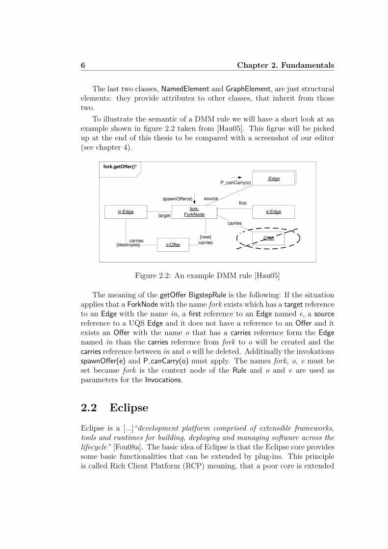
To illustrate the semantic of a DMM rule we will have a short look at anexample shown in figure 2.2 taken from [Hau05]. This figrue will be pickedup at the end of this thesis to be compared with a screenshot of our editor(see chapter 4).
fork.getOffer()*
in:Edgefork:
ForkNodee:Edge
o:Offer
{new}
carries{destroyed}
target
firstspawnOffer(e)
carries:Offer
carries
source
:EdgeP_canCarry(o)
Figure 2.2: An example DMM rule [Hau05]
The meaning of the getOffer BigstepRule is the following: If the situationapplies that a ForkNode with the name fork exists which has a target referenceto an Edge with the name in, a first reference to an Edge named e, a sourcereference to a UQS Edge and it does not have a reference to an Offer and itexists an Offer with the name o that has a carries reference form the Edgenamed in than the carries reference from fork to o will be created and thecarries reference between in and o will be deleted. Additinally the invokationsspawnOffer(e) and P canCarry(o) must apply. The names fork, o, e must beset because fork is the context node of the Rule and o and e are used asparameters for the Invocations.
2.2 EclipseEclipse is a [...]“development platform comprised of extensible frameworks,tools and runtimes for building, deploying and managing software across thelifecycle” [Fou08a]. The basic idea of Eclipse is that the Eclipse core providessome basic functionalities that can be extended by plug-ins. This principleis called Rich Client Platform (RCP) meaning, that a poor core is extended

2.2. Eclipse 7
by clients that contain the desired functionality.Eclipse was originally developed by IBM in 2001 and is an open source
project. In 2004 the Eclipse Foundation, a not-for-profit corporation, wasfounded and thenceforward takes care of the Eclipse development and theEclipse community. The fact, that Eclipse is open source software bestowsit a high usage in research fields.
But not only research institutions use Eclipse. The most popular com-mercial Eclipse based applications are Lotus Notes from IBM and Flex fromAdobe.
Both, the extensibility and that Eclipse is open source, are reasons whywe chose Eclipse. Furthermore the existence of other Eclipse plug-ins whichshall cooperate with the DMM editor cause the choice of Eclipse.
The Eclipse Foundation is hosting a lot of different Eclipse projects. Theprobably most known is the Java Development Tools Project providing anIntegrated Development Environment (IDE) for Java. But there are manymore projects, e.g. for model development, Service Oriented Architecture(SOA) or test and performance tools. The Eclipse Foundation provides theseprojects with newsgroups, wikis, coordinational work and more.
Since version 3.0 Eclipse is based on the Equinox framework, which isa Java implementation of the Open Services Gateway initiative (OSGi) andan Eclipse project by its own. OSGi is a hardware independent Java basedservice platform specification for networks which follows the SOA principalsand is maintained by the OSGi Alliance, that was founded in 1999. The OSGiAlliance specifies the Application Programming Interface (API), provides areference implementation and test suites. One of the biggest benefits of OSGiis that it provides the possibility to dynamically load or unload bundles intothe system in runtime. This feature determines the architecture of Eclipsewhich is shown in figure 2.3. Eclipse is divided into a core and several plug-ins. Every additional functionality, like a user interface, CVS or SVN supportis added to Eclipse by plug-ins [All08].
The core itself consists of a runtime environment (mainly Equinox) thatprovides Eclipse with the basic functionality (like the ability to load plug-ins)and the workspace, which manages all projects that a user is working on.
The Graphical User Interface (GUI) of Eclipse is based on the StandardWidget Toolkit (SWT) and JFace. SWT was developed for Eclipse by IBMin 2001 and is now maintained by the Eclipse Foundation. SWT provides anAPI for graphical user interfaces. Unlike other Java GUIs (e.g. Swing), SWTis using the native operating system API resulting in a better functional andvisual integration of the software into the operating system environment. For

8 Chapter 2. Fundamentals
Figure 2.3: Overview of the Eclipse architecture (based on [GB04])
instance is the file chooser dialog of a SWT application the file chooser dialogof the operating system with all its functionalities like setting up folder orusing the clipboard.
JFace is based on SWT and is a toolkit for graphical user interface devel-opment in Java and “provides helper classes for developing UI features thatcan be tedious to implement” [Fou].
The workbench, which is based on SWT and JFace, is the window whichEclipse opens on start. It consists of the menu bar, the symbol bar, thestatus line and several perspectives. A perspective is a set of different viewsand editors.
Lets have a second glance at the plug-ins because they are very importantfor us. As mentioned before Eclipse extend its functionality by using plug-ins. To avoid that Eclipse loads too many plug-ins it follows the lazy loadphilosophy, meaning that a plug-in is only loaded when it is needed. Thisleads to a separation of the declaration of a plug-in and its implementation.All abilities and dependencies of a plug-in are written down in the Manifestof a plug-in.
To allow the re-use and extension of plug-ins Eclipse, introduces extensionpoints. An extension point is an interface which can be used by extensionsfrom other plug-ins. A plug-in can have several extension point and alsoseveral extensions of extension points from other plug-ins. The extensionsand extension points also need to be declared in the Manifest. This is agreat functionality which can be used to outsource customized code. Thecustomized code can be placed in a separate plug-in which uses the extension

2.2. Eclipse 9
points of the generated plug-in. So the code, which is generated out of modelsis not touched but extended through an additional plug-in. For us, thissolution has the benefit, that if code is re-generated no customized code willbe overwritten (see section 3.2.5) [GB04].
2.2.1 Eclipse Modeling Framework
The Eclipse Modeling Framework project is “a modeling [Java] frameworkand code generation facility for building tools and other applications based ona structured data model” [Fou08b].
We need EMF because GMF, which we will use to generate the visualeditor, is based on EMF and GEF. Because of this, the abstract syntax ofDMM was modeled using EMF (by Christian Soltenborn).
EMF consists of three main parts:
• EMF.Core
• EMF.Edit
• EMF.Codegen
EMF.Core The EMF.Core contains an implementation of the EssentialMeta Object Facility (EMOF) (also called MOF 2.0), which was definedby the OMG. This implementation is called Ecore and so its models arenamed ecore models or domain models. MOF is a meta-meta language whichwas designed to describe meta languages in such a way that it is possibleto export and import (also across networks) created models. This is en-sured by the OMGs standard format for model storage: The XML MetadataInterchange (XMI), which is based on eXtensible Markup Language (XML).Since Ecore implements EMOF, every element of a model generated withEMF is serializable (into an XMI file). So it is possible to export modelsform Ecore to EMOF and vice versa [Groa].
MOF defines four different layers which are shown in figure 2.4. TheDMM is settled in layer M2 while a ruleset, which can be created with oureditor, belongs to layer M1.
EMF provides its models also with a notification function, which is usefulfor Model View Controller (MVC) applications. The MVC pattern suggestsa separation between model, view and controller. We will have a closer lookat MVC in section 2.2.2. For now it is just interesting, that if a model ischanged, the controller needs to know this to inform the view, which for their

10 Chapter 2. Fundamentals
Figure 2.4: The four layers defined by MOF
part redraws the visual representation. This is done via notifications. Everyclass in a domain model (or ecore model) inherits the notification ability fromthe base interface EObject.
An ecore model can be generated in different ways:
• from an XMI file (written by hand or exported from a program thatalso supports EMOF).
• from an XML Schema Definition (XSD).
• from annotated Java code.
• from a Rational Rose model.
• via tree editor provided by EMF.
EMF.Edit The EMF.Edit framework is based on the EMF.Core frame-work. It provides the ability to generate adapter classes that enable viewingof the model elements in the standard (JFace) viewers and property sheets.It also provides command based editing through the EditingDomain interface.All commands are stored in a command stack which provides undo and redofunctionality. The EMF.Edit framework allows to generate a tree editor withvalidation functions for an Ecore model.
EMF.Codegen The EMF.Codegen provides the ability to generate Javacode from a domain (Ecore) model. For each class in a given domain model,

2.2. Eclipse 11
a Java interface with the needed getter and setter methods will be generatedalong with an implementation and factories to create instances of the domainmodel classes.
So the whole generating process starts with a model in (annotated) Javacode or XML, which is used to generate an Ecore model. From this domainmodel a domain generation model (.genmodel) can be generated. This domaingeneration model is like a configuration file for the generator and allows tomodify the code which will be generated. From the domain generation modelthe model code (meaning the Java classes) can be generated, and also a treeeditor for the model and adapter classes (ItemProviders) for viewing themodel elements.
The interested reader can find more information about EMF in [Fou08b,MDG+04].
The next paragraph introduces the Object Constraint Language (OCL)which can be used to provide a model with conditions that influence thestructural properties of the model. OCL can be used in EMF models.
Object Constraint Language
The Object Constraint Language was developed by IBM to describe rules forUML diagrams that typically describe invariant conditions. OCL is now partof UML and maintained by the OMG. OCL 2.0 was developed in parallelwith UML 2.0 and Meta Object Facility (MOF) 2.0 and is capable to be usedin any MOF conform meta model and not just in UML models. So OCL isplatform independent. The specification of OCL can be found in [Grob].
An OCL constraint consists of four parts:
• a context
• a property
• an operation
• keywords
The context defines the element to which the constraint shall be applied.This is usually an element of the model.
The property defines some characteristics of the context. If e.g. thecontext is a class, the property can be an attribute or association.

12 Chapter 2. Fundamentals
The operation describes the condition. It can be e.g. an arithmetical ora set orientated operation.
Keywords are used to modify and compose operations. Keywords are e.g.not, and, or, implies, if, then, else, etc.
We need OCL to define several conditions, e.g. the following one: Theassociation overwrittenRules is used to overwrite one ore more Rules with an-other Rule, but a Rule that overwrites a BigstepRule must also be a BigstepRuleitself. Another example is that the Rule name must not be empty. This twoexamples can be implemented in the following way:
• self.oclIsTypeOf(BigstepRule) and oppositeEnd.oclIsTypeOf(BigstepRule)
• self.name.size()>0
2.2.2 Graphical Editing Framework
The Graphical Editing Framework is a framework for generating rich graph-ical editors out of a domain model. This means that the generated editoris an Eclipse plug-in which needs the Eclipse core to run. GEF makes norestrictions on the underlying model, it can be an EMF model, Java code,etc. GEF follows the MVC concept, meaning that there is a separation be-tween the model, its graphical representation (view) and the program logic(controller).
The model contains the data structure (e.g. classes and references) andis used for storage. Its is helpful (but GEF does not require) that the modelprovides a kind of notification functionality which informs the controller afterany changes on the data.
The view is the graphical representation of the model. In GEF the viewis based on Draw2D. The view offers several operations to manipulate thedata. This can be editing of element properties (in the property view), copyand paste of elements, drag and drop functionality, context menu items orzooming functionality. The palette is also part of the view of a GEF editorand contains buttons for the creation of new elements.
The controller keeps both model and view synchronized. If e.g. a contextmenu function is activated on an element, the view informs the controllerabout this event and the controller applies the necessary function on themodel. GEF offers commands for this purpose, that additionally issue anundo and redo functionality.
GEF consists of two Eclipse plug-ins:

2.2. Eclipse 13
• Draw2D (org.eclipse.draw2d)
• GEF (org.eclipse.gef)
Draw2D provides a lightweight graphical system that is based on (theheavyweight) SWT. A lightweight graphical system is a system that is nestedinside a heavyweight system. Draw2D manages the painting and mouseevents in the view. The graphical elements in Draw2D are called figures andare treated like windows in a heavyweight system, so they have arbitraryshapes, can be transparent, can have the focus and be selected, get mouseevents, etc. All figures are placed on a single canvas. Draw2D does notdepend on GEF, it can be used stand-alone to create graphical views forarbitrary (Java) applications.
While the Draw2D package contains the framework for the view, the GEFpackage contains the framework for the controller. Its central elements arethe EditParts. They are doing the mapping between an element of the modeland a figure of the view. For every model class an EditPart is needed, so theclass hierarchy for the EditParts is the same as for the model classes. But notonly for the classes, also associations need their EditParts (a specialized one,the ConnectionEditPart) which connects the two EditParts corresponding tothe classes connected by the association in the model.
The communication in GEF is done via requests. For instance a Cre-ateRequest is used to create a new element. The communication chain of arequest is shown in figure 2.5.
As seen in figure 2.5, an EditPart forwards a request to an EditPolicy.EditPolicies define what an EditPart can do, they contain the main part ofthe controller logic. An EditPart without its EditPolicies would just be a linkbetween the graphical figure and the model element. [MDG+04, Fou08c]
2.2.3 Graphical Modeling Framework
By now we have introduced EMF, a framework to describe and implementmeta models, and GEF, a framework to generate Eclipse based rich graphicaleditors from arbitrary models. Although these two components would besufficient for implementing our editor the additional use of the GraphicalModeling Framework makes development much more comfortable and allowsus to develop completely model driven up to a certain point which we wouldlike to discuss in the next chapter.
GMF can be considered as a bridge between EMF and GEF (see fig-ure 2.6). It generates a GEF editor from an EMF model. For this purpose

14 Chapter 2. Fundamentals
Figure 2.5: GEF communication chain [MDG+04]
it uses features of EMF like the command infrastructure, the adapter classesor the ItemProviders. But these benefits of EMF are bought by giving upthe model independency of GEF: GMF only accepts EMF model as input.
GMF consists of two main parts:
• a runtime environment
• a generation framework
The runtime provides some GMF specific functionality. It extends partsof the EMF framework, e.g. clipboard support for EMF or an extension ofthe EMF element types. GMF also extends the GEF framework, e.g. newDraw2D figures are added.
The generation framework contains special editors to handle the GMFmodels and a generator which produces the editor code from the GMF mod-els. GMF uses four different models - three to create the mapping between an(EMF) Ecore model and its (GEF) visual representation and one to generatethe editor code:
• the graphical definition model (.gmfgraph)
• the tooling definition model (.gmftool)

2.2. Eclipse 15
• the mapping model (.gmfmap)
• the diagram editor generation model (.gmfgen)
The graphical definition model defines the graphical representation of thedomain model elements. Every element of the domain model (.ecore) whichshall be displayed needs a representative in the graphical definition model.This concerns the classes which need a node entry, and also the connections,which need a connection entry. Every node and connection has a figuredescriptor which defines its visual appearance using GEF figures. If severalnodes shall have the same visual representation, they can share the samefigure descriptor. These correlations are shown in figure 2.6.
Figure 2.6: Correlation between .ecore and the mapping of .gmfgraph and.gmfmap
The tooling definition model defines the palette of the visual editor. Forevery node of the graphical definition model which shall be createable withthe visual editor, a creation tool is needed. The tooling definition model alsodefines the icon of every creation tool which is displayed in the palette of theeditor. The tooling definition model is also intended to create context menuentries for the editor, but this feature is not implemented until now (GMFbuild id 2.0.1).
The mapping model combines our three models: the domain model, thegraphical definition model and the tooling model. Whereas the graphical def-inition model just defines the visual appearance of an element of the domainmodel, the mapping model does the mapping between the graphical repre-sentation and the model (see figure 2.6). The mapping model also links theelements of the domain model to its creation tools in the tooling definition

16 Chapter 2. Fundamentals
model. OCL constraints can also be added here. Constraints for connectioncan be added directly as link constraints to the link mapping, while otherconstraints need to be placed in audit containers. This is useful as connec-tions shall only be placed if the corresponding conditions are achieved whileother constraints may not need to avoid the creation of an element.
From the mapping model and the domain generation model of the Ecorefile the diagram editor generation model can be derived. The diagram editorgeneration model can be considered as a configuration file for the generator(similar to the .genmodel of EMF). It allows for instance to enable or disablevalidation functions for the editor or the setting of the plug-in name. Fromthe diagram editor generation model the generator creates Java code in termsof an Eclipse plug-in.
Figure 2.7: The EMF and GMF models and their relations
The relation between all this models is shown in figure 2.7. GEF providesa number of wizards to help creating (deriving) all needed models from thedomain model, so the developer can focus on the customization fo the models.
Chapter 3
Implementation
This chapter describes the implementation of the DMM editor. It starts witha discussion of the requirements of the editor in section 3.1 which lead to thecognition that we need to built two cooperating editors. These two editorscan be considered as two different views on the same model.
The user of our DMM editor will not notice that he or she is workingwith two different editors: To the outside they seem to be one editor buttechnically they are two separate editors that can be used stand-alone andconsists of two different Eclipse plug-ins. To distinguish between these levels,we from now on mean the one editor that appears to the user if we talk aboutthe DMM editor.
After determining the requirements for both editors, section 3.2 describesthe development of the DMM editor. It first explains the four used GMFmodels mentioned in section 2.2.3. Therafter it shows how the cooperationbetween these two editors works and then discusses a GMF specific problemthat forces us to develop four editor plug-ins.
Section 3.3 mentions the open problems. These are divided into problemsconcerning the GMF models and those concerning the GMF runtime API.Problems concerning the DMM editor are discussed in section 4.1.
3.1 RequirementsThe editor shall be able to visually create a DMM ruleset. Thereby thevisual representation shall be easy to understand. As the target audienceof the DMM editor will be people who are familiar with UML we want touse a visual representation that is similar to object diagrams. As this wasthe intention Hausmann considered in the development of his visual DMM
17
18 Chapter 3. Implementation
representation, our editor shall follow the one used in [Hau05].A ruleset describes the dynamic semantics of a language and needs a
static semantic as meta model (see section 2.1). So the editor needs to offerthe functionality to load a domain model as a meta model.
The editor shall be able to save the visually created ruleset in an XMLfile which can be used as input for other plug-ins.
A Ruleset consists of several Rules which can overwrite each other (seefigure 2.1 on page 5). A Rule itself consists of several Nodes, Edges andInvocations. To keep the overview, the content of a rule shall be displayed ina different editor window. So if a user double clicks on a Rule, a new windowshould open showing the Nodes, Edges and Invocations the rule consists of.So we have two different views on the same model.
Consequently we have to develop two editors: one for rulesets and onefor rules. These two editors have to cooperate in such a way that the ruleseteditor opens the rule editor with the corresponding rule as root element whena rule is double clicked.
Section 3.1.1 describes the requirements for the ruleset editor while sec-tion 3.1.2 describes the requirements of the rule editor. Both section arestructured as follows:
1. description of creation requirements
2. description of optical requirements
3. description of constraints
As the usage of the DMM editor shall lead to one ruleset, both editorshave to operate on the same file. This is described in section 3.2.3.
3.1.1 Ruleset Editor
Creation Requirements A Ruleset consists of rules that can overwriteother rules using the overwrittenRules association. So the ruleset editor mustbe able to create overwrittenRules associations and, as rule is an abstractclass, the inheriting classes BigstepRule, SmallstepRule and PremiseRule (seefigure 2.1 on page 5).
Optical Requirements All of theses three rules shall be graphically rep-resented by a rectangle containing a label. The label displays the contextnode of a rule, followed by the name of the rule. Context node and name

3.1. Requirements 19
are separated by a dot. The name is followed by the parameter nodes of arule framed in parentheses. Each parameter node is displayed with its nameand type separated by a colon. The label of a BigstepRule shall end with anasterisk behind the parentheses while the name of a PremiseRule must alwayshave a “P ” prefixed. The link representing an overwrittenRules shall be anarrow as used for inheritance in class diagrams.
Constraints Besides the graphical representation, the following constraintsshall be maintained while creating these elements: The name and the contextnode of a rule must not be empty and as only a BigstepRule can overwriteanother BigstepRule (the same applies for a SmallstepRule and a PremiseRule)the ruleset editor shall only allow overwrittenRules that follow this constraint.Also a rule shall not overwrite itself.
3.1.2 Rule Editor
Creation Requirements A Rule consists of Nodes, Edges and Invocationsas we can see in figure 2.1 on page 5. Thus the rule editor needs to have theability of creating these three classes using the palette of the editor.
Optical Requirements An example of the desired graphical representa-tion of a (Bigstep-)Rule taken from [Hau05] is shown in figure 2.2 on page 6.In the following we will explain the appearance explicitly:
A label with the name and the context node of a rule is placed in the leftupper corner framed by a rectangle with a clipped corner.
A Node shall be graphically represented by a rectangle with a label. Thelabel shall contain the name of the Node and the type of the node. Both areseparated by a colon and underlined.
Edges can be placed between two Nodes (in the same rule) and shallbe visualized by an arrow. To visualize the navigation direction we useddifferent than in [Hau05] an arrow with an open head. An Edge has a labelthat contains the name of the reference to which the Edge corresponds in themeta model.
Nodes and Edges have the attribute role. A role can hold one of thefollowing values: exists, not exists, destroy or create. The value exists is notvisually emphasized. The literals destroy and create are attached as labelsin curly braces to the corresponding element (as it is done in UML). Thenot exists value is graphically represented by a crossed dashed circle that liesover the concerned element.
20 Chapter 3. Implementation
Besides the role, Nodes and Edges have the boolean attribute UQS. If itis set to true, the concerned element shall be displayed with a second shapebehind it. Both attributes, role and UQS, shall be adjustable via a contextmenu entry.
Invocations shall be visualized as an arrow with a filled head which hasa label at the end and is pointing to the target node of the Invocation. Thelabel contains the sequence number of the Invocation, followed by a colon andthe name of the invoked rule. Thereafter follow the parameters framed inparentheses.
Constraints The creation of these graphical elements shall obey the fol-lowing constraints:
While the name of a Node can be empty it must be unique in its rule ifit is set. A Node without a name cannot be used as a context node or as aparameter. The type of a Node must be set.
An Edge can only be placed between two Nodes if the types of the nodesare the same (or sub types) as the types of the Nodes which are connectedby the reference in the meta model.
While the sequence number of an Invocation is optional, the invoked ruleneeds to be set. The editor shall validate that an entered invoked rule existsin the Ruleset and that the target node of the Invocation has the same type (ora sub type) as the context node of the invoked rule. Also the parameters ofthe Invocation need to have the same types (or sub types) as the parametersof the invoked rule.
3.2 RealizationThe complete development process of the DMM editor is done in Eclipseusing GMF. So for both of our desired editors we will implement an Eclipseplug-in.
This section describes how the required GMF models were created. Italso describes why particular design decisions were made, which problemsoccurred during the development process and how they were solved.
Normally GMF uses the domain model, the graphical definition modeland the tooling definition model to generate the mapping model. From themapping model the diagram editor generation model can be derived (addi-tionally using the domain generation model). The diagram editor generationmodel is then used to generate the editor plug-in (the whole correlation is

3.2. Realization 21
shown in figure 2.7 on page 16). So we need these four models for both ofour desired editors. But what is the difference between the models of theruleset editor and the models of the rule editor?
Every graphical element of the DMM editor is mapped to a correspondingelement in the domain model using the mapping model. The main differencebetween the ruleset and the rule editor is the mapping of the canvas (thearea on which the editing/drawing takes place).
The canvas of the ruleset editor is mapped to the Ruleset class in thedomain model. So all elements which are placed on the canvas are part ofthe Ruleset. As a Ruleset consists of Rules, it is only possible to place ruleson the ruleset editor canvas.
In contrast, the canvas of the rule editor is mapped to the Rule class inthe domain model. Because a Rule consists of Nodes, Edges and Invocationsthe rule editor only allows to place these three element types on the canvas.
Section 3.2.1 describes the different GMF models used for both editorsin detail. Section 3.2.2 explains how the needed constraints which the editorshall fulfill are realized. In section 3.2.3 the technique for impelmenting thetwo different views on the model is described while section 3.2.4 covers aGMF specific problem that forces us to increase the number of used models.
Up to this point everything can be developed completely model driven.But some features will require custom code. Section 3.2.5 covers these fea-tures and their implementations. Thereby it distinguishes between featuresthat can be implemented in a customized plug-in (using extension points ofthe generated code) and features that need to be placed directly into thegenerated code.
3.2.1 GMF Models
This section describes the needed GMF models for both editors in the fol-lowing order:
1. graphical definition model
2. tooling definition model
3. mapping model
4. diagram editor generation model
The correlation of these models is shown in figure 3.1.

22 Chapter 3. Implementation
Figure 3.1: Correlation of the GMF models of the DMM editor
Graphical Definition Model
As we have seen in section 2.2.3, the graphical definition model contains anentry for every part of the domain model that shall be displayed. This cane.g. be classes that are usually represented by diagram nodes, associationsthat are usually represented by connections or attributes which are usuallyrepresented by labels.
For the graphical definition model the situation is a bit different thanfor the other models. On the one hand we could use two separate graphicaldefinition models: one containing the visual representations of a Ruleset andone containing the visual representation of a Rule. On the other hand wecould use one common graphical definition model containing both visualrepresentations. As we prefer to minimize the number of different models (ifthere is no benefit using additional ones) we decided to use only one graphicaldefinition model (the ruleset.gmfgraph).
The structure of the graphical definition model is a tree with the canvasof the editor as the root node. All the elements mentioned above are directchildren of the canvas node.
As we use one graphical definition model for both editor plug-ins, it mustcontain all elements of the domain model which we want to display. This

3.2. Realization 23
leads to a diagram node for each of the following elements: BigstepRule,SmallstepRule, PremiseRule, Node, Invocation and Edge.
Connections are needed for the overwrittenRules, the Edge and the Invo-cation.
It may attract the attention that the Invocation has a diagram node repre-sentative and a connection representative. It would be sufficient to representthe Invocation by a label and a connection that points to the target node ofthe Invocation. But a connection always needs a target and a source node.So we decided to bind the label to an invisible node that can take the role ofthe source node of an Invocation connection.
We also need labels to display the names for each of the three rules, onelabel to display the name of the Node and one label to display the referenceof the Edge.
The last child of the canvas node is the figure gallery. It contains the figuredescriptors. Every node, connection and label has a figure descriptor. Afigure descriptor can combine several elements. For instance the PremiseRulefigure descriptor combines the node for the PremiseRule and the label for thePremiseRule. It also defines the visual appearance by using GEF figures.
The figure gallery also contains the decorators for connections. As wewant to display the overwrittenRules as an arrow with a head similar to thoseof an inheritance in class diagrams, we need a special polygone decorator. Wealso need a polygon decorator for the Edge connection and for the Invocationconnection.
Tooling Definition Model
For the tooling definition model the situation is nearly the same as mentionedfor the graphical definition model. But if only one tooling definition modelwould be used, both editors would have all creation buttons in their palette.This would be confusing because e.g. a ruleset editor should not be able tocreate Nodes or Edges. In fact it is not able to create those elements as there isno mapping for Nodes or Edges between the model and the view in the rulesetmapping model. In the editor this would results in a deactivated cursorfor those elements. But the palette displays every creation tool, also thosewhich are not used in the mapping model. This could be avoided by deletingthe entries for those buttons of the palette in the diagram editor generationmodel. But every new creation of the diagram editor generation model wouldoverwrite these changes. So we decided to implement two different toolingdefinition models: one for the ruleset editor and one for the rule editor.

24 Chapter 3. Implementation
The tooling definition model is structured similar to the graphical defi-nition model as a tree. The root node is the tool registry. The tool registryhas a child node palette that describes the palette of the editor. The paletteneeds to have a creation tool child node for every element of the domainmodel that shall be createable with the ruleset editor.
The tool registry node can also have child nodes that create entries inthe main menu or the context menu. Unfortunately the one for entries inthe context menu is not working in the current GMF release (GMF build id2.0.1, see section 3.3).
So the tooling definition model for the ruleset editor needs a creation toolfor each of the classes BigstepRule, SmallstepRule and PremiseRule and onecreation tool for the association overwrittenRules.
The tooling definition model for the rule editor differs only in its creationtools from the ruleset tooling definition model. It needs a creation tool foreach of the three classes Node, Edge and Invocation and one for the invocationconnection.
Mapping Model
The mapping model combines the domain model with the graphical definitionmodel and the tooling definition model. It is structured like the other GMFmodels as a tree, with the mapping node as the root node. The mapping nodecan have different child nodes like a top node reference node, a link mappingnode, an audit container (see section 3.2.2) node or a canvas mapping node.
We will now first describe the mapping model for the ruleset editor andthen mention the differences to the rule mapping model.
As mentioned before, the corresponding classes of the elements which aredirectly placed on the canvas have a part-of relation to the correspondingelement of the canvas. These elements are mapped to the correspondingreference in the domain model by the containment feature of the top nodereference. So our Rules are mapped to the Rule reference of the domainmodel element Ruleset.
The correlation between the nodes of the domain mapping model and thenodes of the other models is shown (a little simplified) in figure 3.2
We need a top node reference node for each of the diagram nodes from thegraphical definition model that shall be createable in our ruleset editor: onefor the BigstepRule, one for the SmallstepRule and one for the PremiseRule.Every top node reference has a node mapping child node. This node doesthe mapping between the element in the domain model, the diagram node in

3.2. Realization 25
Figure 3.2: Mapping of the ruleset.gmfmap between the ruleset.gmftool, theruleset.gmfgraph and the ruleset.ecore
the graphical definition model and the creation tool in the tooling definitionmodel. Each of our three rules has a label and so every node mappingnode has a feature label mapping child node. The feature label mapping isresponsible for the mapping of the label to the attribute of the element inthe domain model. So our three feature label mappings link the label of theirRule to the name attribute of the corresponding Rule in the domain element.
The link mapping node implements the mapping between the referencein the domain model, the connection in the graphical definition model andthe creation tool in the tooling definition model. Our ruleset mapping modelhas only one link mapping node, the one for the overwrittenRules reference.
The canvas mapping links the diagram canvas of the graphical definitionmodel to an element of the domain model (in this case to the Ruleset) andselects the palette for the editor from the tooling definition model.
26 Chapter 3. Implementation
The mapping model for the rule editor is structured similar to the rolsetmapping model. It needs a top node reference for the Node and one for theInvocation. Both have an according node mapping child node which has afeature label mapping node.
The second top node reference is needed because we modeled the graphicalrepresentation of the Invocation as mentioned above with an invisible nodecontaining the label and a separate connection. From now on this connectionis called invocation edge. So the domain model element Invocation is mappedto the invisible node with its label. The invocation edge is only for graphicalpurposes.
For the Edge and the invocation edge a link mapping node is needed. Thelink mapping of the invocation edge just links the graphical representationto the creation tool, there is no binding to a domain model element. Thelink mapping node of the Edge has a feature label mapping child node forthe label.
Diagram Editor Generation Model
The diagram editor generation model is based on the mapping model andthe generation model and is used to generate the Java code of the editor. Itis structured as a tree with the gen editor generation node as the root node.
The root node has several child nodes that offer customization optionsfor different parts of the editor. For instance, the gen plugin node allows tochange the name of the generated plug-in or the property sheet node allowsto customize the property sheet.
For us, the most interesting child node is the gen diagram node. It has achild for every top node reference and a link mapping node from the mappingmodel. Here they are called gen top level node and gen link. Every gen toplevel node and gen link node (as their childs) gets a visual ID which is forinstance used to determine of what type the selected object in the editor is(and then apply type specific functions).
3.2.2 Constraints
As we have seen in section 3.1 the DMM editor has to ensure the maintain-ing of several conditions. GMF offers two places where constraints can beimplemented - both are situated in the mapping model:
• Constraints for connections can be placed as link constraint child nodesof the link mapping node. They are divided in source and target node

3.2. Realization 27
constraints.
• All other constraints need to be added as constraint node to the auditcontainer node. If there are many constraints the audit container can bestructured in several child audit containers to achive a better overview.
The difference between link constraints and other constraints is that a linkconstraint is allways checked on runtime and therefore avoids the creation of aconnection that violates one of its condition. For the other constraints it canbe adjusted if they shall be checked on runtime or just when the validationfunction in the editor is explicitly performed.
Every constraint needs a context elemenet on which it shall be applied.For a link constraint the context is implicitly given as it is the child nodeof one link mapping that corresponds unambiguously to an element of thedomain model. For the other constraints the context needs to be explicitlyset.
GMF offeres several ways of formulating the condition. It can be e.g. Javacode, a regular expression or formulated in OCL. As we want to stay platformindependent for as long as possible we decided to use OCL constraints.
In the ruleset mapping model we added a link constraint to ensure thata BigstepRule only overwrites other BigstepRules (as for SmallstepRules andPremiseRules). We also used a constraint to ensure that all Rule names arenot empty.
In the rule mapping model we created two link constraints for the Edgelink mapping: one for the target node and one for the source node. Bothensure that the types of the source and target node are set. This is importantas the reference that is displayed in the label of the Edge figure needs to existin the meta model and its connected nodes need to have the same types(or super types) as the Nodes that are connected by the Edge. A “normal”constraint is used to ensure that when a node’s name is set it is unique inthe Rule.
3.2.3 Diagram Partitioning
As mentioned above we want to have two different views for one model,which technically means that two different editors work on the same XMLfile. The technique to accomplish this is called diagram partitioning. Theelement which is double clicked to open the other editor is called partitioningelement. Our partitioning element is Rule.
As we want two different editors we need two different diagram editor
28 Chapter 3. Implementation
generation models. For this purpose we need two mapping models, one forthe rule editor and one for the ruleset editor.
As both editors shall follow the same meta model (the one shown infigure 2.1), both mapping models need to be based on the same domainmodel (the ruleset.ecore file).
Up to this point we have all needed models for the diagram partitioningbut we still need to tell the ruleset editor that it shall open the rule editorafter double clicking a rule. This is done in the diagram editor generationmodel. An open diagram behaviour node has to be added to the gen toplevel node of the partitioning element. In the open diagram behaviour nodethe diagram kind needs to be specified (in our case Rule) and the ID of theeditor which shall be opened after double clicking the partitioning element.The editor ID is found in the gen editor view node of the rule diagram editordomain model.
3.2.4 Abstract Rule Problem
As mentioned in the previous section our partitioning element is Rule. Thisleads to a GMF specific problem: When the partitioning element is doubleclicked and a new editor opens with the partitioning element as root element,GMF instantiates an object of the partitioning element’s class. The problemis that our partitioning element is abstract.
Although the partitioning element will never really be a Rule (it willalways be a BigstepRule, SmallstepRule or PremiseRule) GMF (until now)does not support an abstract class as partitioning element.
There exist two ways to handle this problem. According to the GMFnewsgroup ([Fou08d]) it is possible to ignore all compilation errors concern-ing the abstract partitioning element and fix the problem manually in thegenerated code. As this causes changes directly in the generated code (andnot by using a customization plug-in) we decided to use the second way: Itis also possible to create three plug-ins, one for every sub class of Rule, anduse three partitioning elements: BigstepRule, SmallstepRule and PremiseRule.
So we need to develop four different editors that work together and appearto be one DMM editor. But the three different rule editors are very similar.As mentioned in the previous section, all three can use the same graphicaldefinition model (ruleset.gmfgraph).
As for these three editors the palette should be the same they can alluse the same tooling definition model (rule.gmftool). The correlation of allmodels that we need is shown in figure 3.3
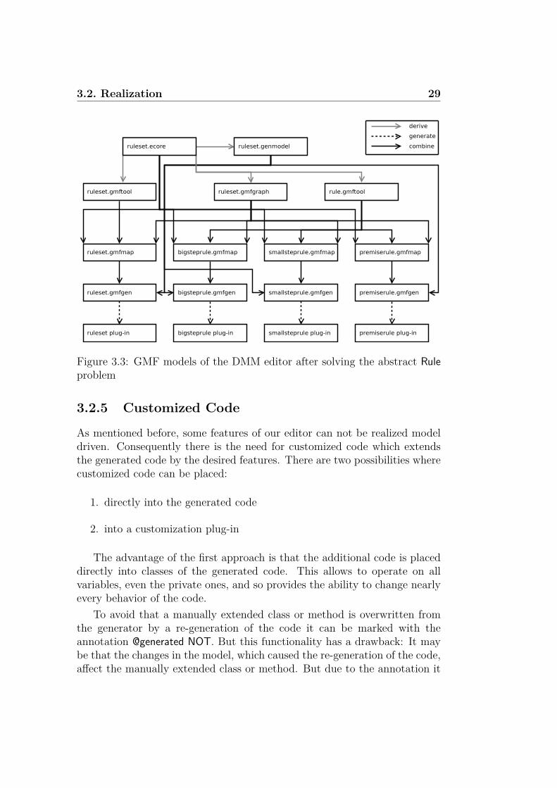
3.2. Realization 29
Figure 3.3: GMF models of the DMM editor after solving the abstract Ruleproblem
3.2.5 Customized Code
As mentioned before, some features of our editor can not be realized modeldriven. Consequently there is the need for customized code which extendsthe generated code by the desired features. There are two possibilities wherecustomized code can be placed:
1. directly into the generated code
2. into a customization plug-in
The advantage of the first approach is that the additional code is placeddirectly into classes of the generated code. This allows to operate on allvariables, even the private ones, and so provides the ability to change nearlyevery behavior of the code.
To avoid that a manually extended class or method is overwritten fromthe generator by a re-generation of the code it can be marked with theannotation @generated NOT. But this functionality has a drawback: It maybe that the changes in the model, which caused the re-generation of the code,affect the manually extended class or method. But due to the annotation it
30 Chapter 3. Implementation
will not be overwritten and therefore the changes that affect the extendedclass or method will not take place in the model code.
This drawback can be avoided with the second approach by using anextension point to extend a class out of another plug-in. But this methodhas two restrictions: the class that shall be extended needs to be providedas an extension point (by the generated plug-in) and it does not allow to useprivate attributes. In exchange the above mentioned problem is avoided andthe customized code is clearly separated from the generated code.
So where possible, we want to use the second approach and only if adesired extension cannot be implemented by using an extension point it shallbe implemented directly into the generated code.
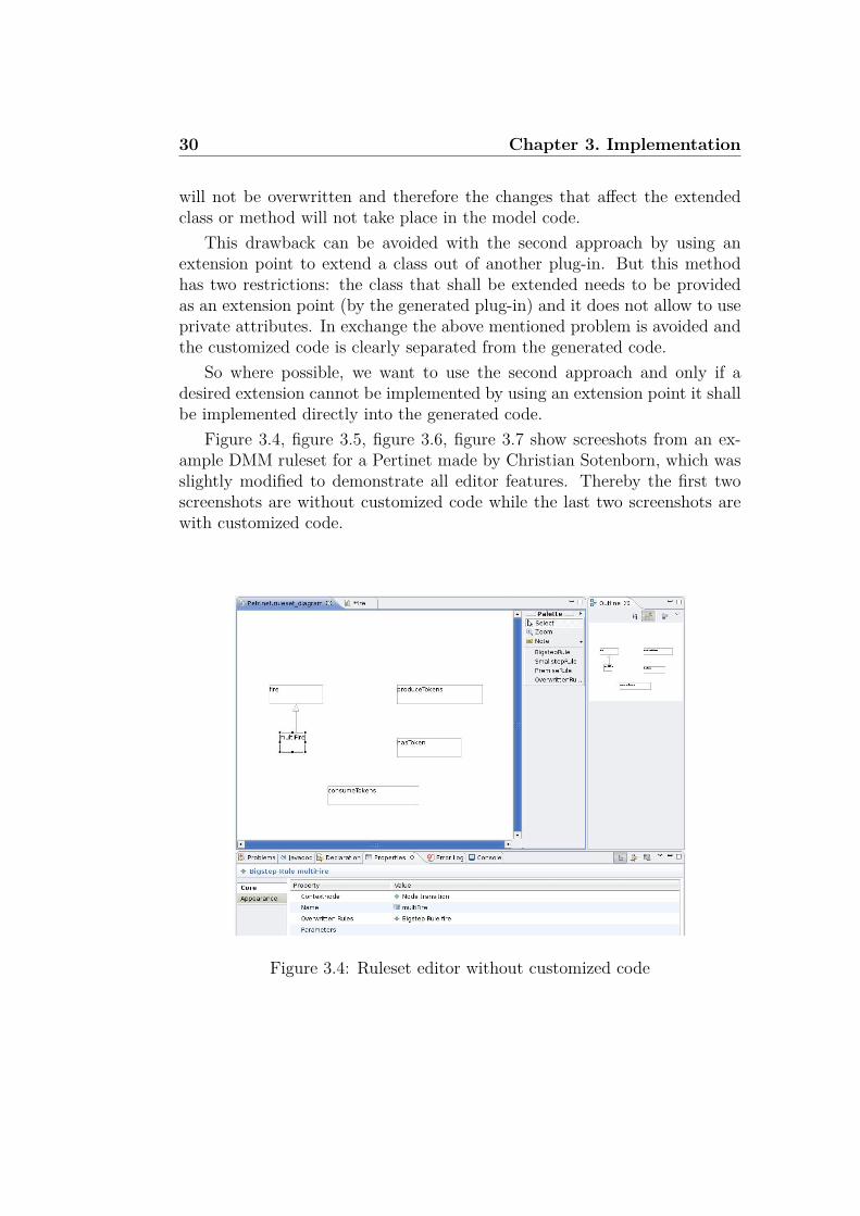
Figure 3.4, figure 3.5, figure 3.6, figure 3.7 show screeshots from an ex-ample DMM ruleset for a Pertinet made by Christian Sotenborn, which wasslightly modified to demonstrate all editor features. Thereby the first twoscreenshots are without customized code while the last two screenshots arewith customized code.
Figure 3.4: Ruleset editor without customized code

3.2. Realization 31
Figure 3.5: Rule editor without customized code
Customization Plug-in
As we prefer that our customization plug-in is only loaded when it is needed(following the lazy load philosophy of Eclipse) we implemented an activa-tor. The following text will describe the different problems which requirecustomized code that can be implemented through extension points. Theseare:
• element labels
• changing the visual representation of elements
• changing the properties of elements
Element Labels As described in section 3.1 some labels of the graphicalelements shall be composed of several attributes. Also some labels shall fol-low certain conditions, e.g. the context node of a Rule (which is part of itsdisplayed label) must exist in the Rule and must have a name. GMF pro-vides the ability to compose labels out of attributes of the domain modelelement that corresponds to the label. But GMF does not offer a modeldriven way to compose a label out of attributes from another than the cor-responding domain model element. Though GMF provides the extension

32 Chapter 3. Implementation
Figure 3.6: Ruleset editor with customized code
point org.eclipse.gmf.runtime.common.ui.services.parserProviders that allows touse specified parsers for certain figures. The parserProvider distinguishes theneeded parser by the visual ID of the selected figure.
A parser allows to compose the content of a label out of arbitrary at-tributes and other text. Its main functionality is realized in four methods:
• getPrintString()
• getEditString()
• isValidEditString()
• getParseCommand()
The getPrintString() method is used to compose the textual content of thelabel which is displayed. Therefore it receives the domain model element thatcorresponds to the label, so it can use all attributes of the affected element.But it can also use the references of the element to access attributes of otherelements.
If a label is selected the in-line editing box opens and the label can beedited. The string that is displayed in the in-line editing box is computedby the getEditString() method. Usually it is the same string as composed

3.2. Realization 33
Figure 3.7: Rule editor with customized code
by the getPrintString() method, but they can differ. This makes sense e.g.if the in-line editing string is too long and the normal visual representationdoes not need to display all the details and so achieves a better overview.For instance the getPrintString() and getEditString() methods of a Rule differ.Among other things the label of a Rule dispays the parameters of the Rule.Each parameter node has a name and a type. As a Rule can have severalparameters this can result in a long string which the getEditString() methodneeds to compute completely. But if a Rule label is not in an editing processthe getPrintString() only displays the names of the parameters, not the types.
After a label was edited, the isValidEditString() method verifies if thestructure of the entered string is correct. But not only the structure can bechecked, also semantic verifications are possible. For instance the referencethat is entered in an Edge label need to exist in the meta model. Also thetypes of the nodes connected by the reference need to be the same (or supertypes) as the types of the Nodes connected by the Edge.
If the isValidEditString() method returns an OK, the getParseCommand()method composes a command that contains a change request of the affectedattributes from the domain model element. As every command is addedto the command stack, this method provides the benefit of an undo/redofunctionality.
34 Chapter 3. Implementation
Changing the Visual Representation of Elements Another problemthat we cannot solve without customized code is the graphical representationof the attributes role and UQS. Because the graphical representation wehave seen in section 3.1 is not implementable without detailed knowledge ofGEF, and this knowledge lies beyond the scope of this thesis, we decided toimplement it in the following way:
The role is emphasized by a color: exists is visualized in black, exists notin red, destroy in blue and create in green. This decision is based on the factthat Groove ([Ren04]) is using these graphical representations and as Grooveis part of the same chain as the DMM editor, most users of our DMM editorwill be familiar with Groove and therefore know the meaning of the chosengraphical representation. So it seems to be a reasonable trade-off.
The UQS is graphically represented by drawing the outline of the figurein dashed lines if the UQS value is set to true.
This is done using the org.eclipse.gmf.runtime.diagram.ui.editpartProvidersextension point. Like the parserProvider the editpartProvider distinguishesbetween the selected figures using the visual ID to determine the neededEditPart. In our case the editpartProvider has to consider the visual ID of theNodeEditPart and the visual ID of the EdgeEditPart. The functionality of thedetermined EditPart consists mainly in the following methods:
• activate()
• handleNotificationEvent()
• addSemanticListeners()
• removeSemanticListeners()
• updateFigure()
The activate() method is called when a class is activated (lazy load) andis used to ensure that the Nodes and Edges of an opened ruleset are displayedcorrectly. Therefore it calls the updateFigure() method.
The handleNotificationEvent() method is called when an attribute of thedomain model element to which the EditPart corresponds is changed. Thenthe handleNotificationEvent() method ensures that the figure is re-drawn bycalling updateFigure().
But it may be required, that a figure is re-drawn when an attribute ofanother element changes. For instance it could be considered to visuallyemphasize a Node which is a contextnode of a Rule. So it may be that a Node
3.2. Realization 35
has to be re-drawn if the contextnode attribute of a Rule changes. Thereforewe need to know when a Rule attribute changes. For this purpose the methodsaddSemanticListeners() and removeSemanticListeners() allow to add or removethe EditPart as listener to other elements.
The method updateFigure() is doing the main work. Depending on the roleattribute it sets the color of the figure and depending on the UQS attributeit sets the outline of the figure to dashed or solid. Thereafter it calls theinvalid() method of the figure which causes the canvas to re-draw the figure.
The editpartProvider is also used to implement another visual effect: thename and type of a Node shall be underlined. Therefore the editpartProvideradditionally considers the visual ID of the NodeNameEditPart which is re-sponsible for the label of the Node figure.
Changing the Properties of Elements Now as we have seen how therole and UQS attributes are visualized, we consider the facilities to set theseattributes. Up to now the only way to change the value of one of theseattributes is to use the property sheet of a Node or an Edge. It would bemuch more comfortable if both attributes could be set in the context menuthat appears after a right click on a Node or an Edge.
As the context menu node in the tooling definition model is not working bynow (see section 3.3) we need to implement the context menu with customizedcode. Therefore we use the extension point org.eclipse.ui.menus. The addedentries use commands to communicate the request of setting an attribute. Forthis purpose we extended the org.eclipse.ui.commands extension point. Usingcommands leads to the benefit (as mentioned in section 2.2.1) of undo/redofunctionality.
Changes in Generated Code
As discussed above we only want to add changes in the generated code ifthere is no possibility of using an extension point.
As seen in section 3.1 the rule editor shall display the name of the rule inthe left upper corner (framed by a rectangle with a clipped corner). As thisrequires detailed GEF knowledge which is out of the scope of this thesis, wedecided to show the name of the rule in the tab name. This leads to a betteroverview if someone has opened several rules of a ruleset.
Actually the tab name should have been overwriteable using the exten-sion point org.eclipse.gmf.runtime.common.ui.services.editorProviders. But un-fortunately this extension point is not working and so we had to place the

36 Chapter 3. Implementation
needed code directly into the generated code. This can be done in the cre-atePartControl() method of the RulesetDiagramEditor class. Here the call ofthe setPartName() method that sets the tab name can be adjusted.
3.3 Open GMF Problems
This section describes the open problems of GMF. These are divided intoproblems concerning the GMF models and those concerning the GMF run-time API. All this problems refere to the GMF build id 2.0.1. Open problemsconcerning the DMM editor are discussed in chapter 4.
GMF Models A problem is that the mapping model cannot deal with acanvas that is linked to an abstract class of the diagram model. This wasalready described in section 3.2.4 as it considers our partitioning element.According to the Eclipse newsgroup there exist workarounds that requirechanges in the generated code.
A problem situated in the tooling definition model concerns the creationof context menu entries. As mentioned above the context menu child nodeof the tool registry is not workling. This is very confusing as context menunodes can be created. A workaround is described in section 3.2.5.
If more than one diagram editor generation model is used (as it is the casein e.g. diagram partitioning), the visual IDs can lead to problems. The issueis that the numbers of these visual IDs are set to standard values that areonly unique inside a plug-in. So it can e.g. be that the visual ID of the gentop level bigstepRuleEditPart of the ruleset plug-in has the same value as thegen link edgeEditPart. As the visual IDs are used to distinguish between thetype of the selected figures this can lead to interference problems. To avoidthese interferences the visual IDs can be changed manually in the diagrameditor generation model.
Every time when changes are applied to a mapping model, the diagrameditor generation model needs to be re-generated. Usually GMF remembersmanually changes in the diagram editor generation model when it is over-written. But for the visual IDs this is not the case. They have to be re-settedafter every re-generation of the diagram editor generation model. The sameapplies for the open diagram behaviour nodes used for the diagram parti-tioning as described in section 3.2.3. They have to be re-created after everyre-generation of the diagram editor generation model.

3.3. Open GMF Problems 37
GMF API The only problem with the GMF API that we noticed duringthe development of our editor is the extension point org.eclipse.gmf.runtime.common.ui.services.editorProviders that does not work. We informed the GMFnewsgroup about this issue - however a suitable solution is still being dis-cussed.

Chapter 4
Conclusion
This chapter contains the conclusion of this bachelor thesis. It starts with asummary of the developed DMM editor and then gives some general remarksconcerning GMF. Finally section 4.1 gives some ideas for future work.
The DMM Editor To this end, we have developed an editor for DMMwith reasonable usability. As desired, the edior provides a graphical repre-sentation of the domain elements. The most important features of our editorare as follows:
• It offers two views on the model: one for the ruleset and one for therules. This leads to a better overview in the ruleset.
• The drawn DMM ruleset can be typed over a meta model that is loadedinto the ruleset.
• The command infrastructure of Eclipse is used, leading to undo/redofunctionality.
• Several constraints have been implemented which ensure that all cre-ated DMM ruleset elements are consistent with each other and fulfilltheir semantic constraints.
To provide an easy way to install our editor, we generated a featureout of all editor plug-ins. It is available on the update site http://wwwcs.uni-paderborn.de/cs/ag-engels/ag˙dt/Research/DMM/.
To demonstrate the achieved outcomes we decided to compare the graph-ical representation of our editor with those used in [Hau05]. Therefore wereproduced the ruleset shown in figure 2.2 on page 6 using our editor. Thescreenshot is shown in figure 4.1.
39

40 Chapter 4. Conclusion
Figure 4.1: Screenshot of our DMM Editor
Lessons Learned If someone is not familiar with Eclipse, EMF, GEF,GMF and model driven development in general, it takes a lot of time to getinto these topics and to be able to use the different models as a matter ofcourse. In the author’s opinion especially the GMF documentation lacks atsome points. The API specification is precise and good but we missed adetailed description of the different GMF models and their elements.
Very helpful for learing to deal with GMF are the tutorials which areprovided on the GMF webpage ([Fou08d]). The webpage also provides awiki and a newsgroup. The latter should only be consulted if the wiki cannothelp. Usually the answers in the newgroup are quick and qualified.
If you are familiar with GMF then it is a mighty tool that allows the userto generate an editor with the basic functionality from an EMF model withinminutes. But up to now for most special features like context menu entry orchanging figure outlines customized code is needed.
4.1 Outlook
This section will discuss some possible extensions of the current version ofthe DMM editor. Generally some usability tests should be performed to be
4.1. Outlook 41
aware of problems of the editor, but some improvements can be consideredwithout these tests.
The probably most useful extension concerns the Invocation. Due to themanner of the Invocation’s graphical representation (see section 3.2.1) theuser needs to create an Invocation and than connect it with the target nodeof the Invocation using an invocation edge. It would be a usability gain ifthe invocation edge would be automatically created and connected to theInvocation, e.g. by using the context menu of a Node.
As mentioned in section 3.2.5, our editor differs form the graphical rep-resentation in [Hau05] in a few points. This could be another possible futurework. It concerns the rule name that is by now only placed in the tab ofthe rule editor window and the graphical representation of the attributes roleand UQS of an Edge or Node.
It is possible to think of a better integration of the DMM editor and theEMF meta model for the static semantic of a desired language. For instance,domain elements of the meta model could be placed via drag and drop ontothe canvas of the DMM editor. The editor could then automatically createnodes which are typed according to the dropped element.
The editor could be provided with more intelligent functions. For in-stance, it could notice if for an Edge only one reference exists in the metamodel which fits with the types of the source and target node of that Edge -the edior could then automatically set the Edge’s reference attribute accord-ingly.
A better integration into the tool chain leading from DMM to Groovewould be desireable. It would be nice if the generation of a Groove ruleset(using the plug-in developed in [Sto08]) could be started from within ourDMM editor.


Appendix A
List of Acronyms
API Application Programming Interface
DMM Dynamic Meta Modeling
DSL Domain Specific Language
EMF Eclipse Modeling Framework
EMOF Essential Meta Object Facility
GEF Graphical Editing Framework
GMF Graphical Modeling Framework
GUI Graphical User Interface
IDE Integrated Development Environment
MDD Model Driven Development
MOF Meta Object Facility
MVC Model View Controller
OCL Object Constraint Language
OMG Object Management Group
OSGi Open Services Gateway initiative
RCP Rich Client Platform
SWT Standard Widget Toolkit
43

44 Chapter A. List of Acronyms
SOA Service Oriented Architecture
UML Unified Modeling Language
UQS Universally Quantified Structure
VML Visual Modeling Language
XMI XML Metadata Interchange
XML eXtensible Markup Language
XSD XML Schema Definition

References
[All08] OSGi Alliance. OSGi homepage, 2008. http://www.osgi.org[Online; accessed 26-February-2008].
[EHHS00] G. Engels, J. H. Hausmann, R. Heckel, and S. Sauer. DynamicMeta-Modeling: A Graphical Approach to the Operational Se-mantics of Behavioral Diagrams in UML. In A. Evans, S. Kent,and B. Selic, editors, UML 2000 - The Unified Modeling Lan-guage, Berlin, October 2000. Springer-Verlag.
[Fou] Eclipse Foundation. The JFace UI framework. http://help.eclipse.org/help32/index.jsp?topic=/org.eclipse.platform.doc.isv/guide/jface.htm [Online; ac-cessed 26-February-2008].
[Fou08a] Eclipse Foundation. About the eclipse foundation, 2008. http://www.eclipse.org/org/ [Online; accessed 26-February-2008].
[Fou08b] Eclipse Foundation. Eclipse modeling framework project, 2008.http://www.eclipse.org/modeling/emf/ [Online; accessed 24-February-2008].
[Fou08c] Eclipse Foundation. Graphical editing framework project, 2008.http://www.eclipse.org/gef/ [Online; accessed 24-February-2008].
[Fou08d] Eclipse Foundation. Graphical modeling framework project,2008. http://www.eclipse.org/gmf/ [Online; accessed 24-February-2008].
[GB04] Erich Gamma and Kent Beck. Eclipse erweitern, Prinzipien, Pat-terns und Plug-Ins. Addison-Wesley, 2004. English title: Con-tributing to Eclipse: Principles, Patterns, and Plug-Ins.
45

46 REFERENCES
[Groa] The Object Management Group. MOF homepage. http://www.omg.org/mof/ [Online; accessed 28-February-2008].
[Grob] The Object Management Group. OCL specification.http://www.omg.org/technology/documents/modeling˙spec˙catalog.htm#OCL [Online; accessed 29-February-2008].
[Hau05] J. H. Hausmann. Dynamic Meta Modeling. PhD thesis, Univer-sity of Paderborn, 2005.
[MDG+04] Bill Moore, David Dean, Anna Gerber, Gunnar Wagenknecht,and Philippe Vanderheyden. Eclipse Development using theGraphical Editing Framework and the Eclipse Modeling Frame-work. IBM redbooks. IBM International Technical Support Or-ganization, 2004.
[Ren04] A. Rensink. The GROOVE Simulator: A Tool for State SpaceGeneration. In J. Pfalz, M. Nagl, and B. Bohlen, editors, Ap-plications of Graph Transformations with Industrial Relevance(AGTIVE), volume 3062 of Lecture Notes in Computer Science,page 479 to 485. Springer-Verlag, 2004.
[Sto08] Boris Stobbe. Automatic Transformation of graph-based DMMrules into GROOVE rules. PhD thesis, University of Paderborn,2008.

Diese Arbeit wurde von mir selbstandig angefertigt. Es wurden keine an-deren als die angegebenen und bei Zitaten kenntlich gemachten Quellen undHilfsmittel benutzt.
Paderborn, den 22.Marz 2008