a venture into extraction of helium from natural gas
TRANSCRIPT

Website : http://www.dae.gov.in ISSN-09929-5523
VOL. 41/NO. 09-10/Mar.-Apr. 2008
Nuclear IndiaA Venture into Extraction of Helium from Natural Gas
A part of the Helium Pilot Plant at GCS Kuthalum, ONGC, Tamilnadu
Helium, because of its extraordinary properties, enjoys distinction amongst other terrestrial gases and finds wide variety of important applications especially in the domain of space, atomic energy, defense and power.
The Helium bearing natural gas is exploited for obtaining Helium in some countries. In India gas reserves containing Helium are very few. The natural gas field at Kuthalum, Tamilnadu gives off raw gas containing about 0.06 vol % Helium. Through a joint technology venture between the Department of Atomic Energy, Department of Science and Oil and Natural Gas Corporation Limited , a Pilot Plant to extract and purify Helium from natural gas to a level better than 99 vol % has been successfully set up at GCS Kuthalum, ONGC, Cauvery Asset, Tamilnadu in February 2008. The participating organizations from DAE are Saha Institute of Nuclear Physics and Variable Energy Cyclotron Centre , Kolkata.
To make the country self-reliant in Grade-A Helium, efforts have been initiated for the extraction of Helium using the conventional route from natural gas sources.

Grade-A Helium, one has to filled beds are utilized in each stage in Helium, because of its extra o rd ina ry p rope r t i e s , en joys approach the extraction of Helium order to process a continuous flow of distinction amongst other terrestrial using the conventional route from gas.gases and finds wide variety of natural gas sources where the flow Equipment which compose the important applications especially in rates are very robust, although the plant are: 13 adsorbent beds, each the domain of space, atomic energy, concentration of Helium is very low, equipped with automated valves, six defence and power. Its high thermal typically in the tune of 0.06 vol % in compressors, four vacuum pumps and conductivity plays a vital role in the Indian Natural Gas fields. Despite nine gas receivers, five of which are heat treatment of optical fibers and high solar and cosmic abundance of rigid pressure vessels and four of acts as a medium of heat transfer in Helium, it is extremely sparse on the which are flexible-walled containers nuclear power generators. Low earth. The very lean quantity of that function near ambient pressure. liquefaction temperature of Helium Helium (~ 5.2 ppm) in the All of the equipment operate makes it desirable for the purging and atmosphere makes it uneconomical unattended utilizing PLC controllers pressurizing of liquid hydrogen for large scale extraction from this to monitor and control the operation. rocket propulsion systems and for source. All equipments are mounted on pre-cryogenic applications; cooling of assembled, modular skids.superconducting magnets and RF A feed stream of 833 NL/min cavities for high energy accelerators The PSA Helium Purification containing 0.06 vol % Helium is e t c . O t h e r u s e s o f H e l i u m System (HPS) separates impurities processed by the HPS, isolating the are welding, leak detection, (N , O , hydrocarbons, CO , H O) majority of the Helium and removing 2 2 2 2
c h r o m a t o g r a p h y, c o n t r o l l e d impurities down to less than 1.0 vol %. f r o m H e l i u m b y f l o w i n g atmosphere etc. There is no substitute The main by-product is enriched contaminated gas through four of Helium wherever the requisite methane, which constitutes 88.5 vol % stages of adsorbent beds at 4-bar temperature is below 17 K. of the feed stream, and it is produced at pressure.
In view of any unforeseen scarcity a purity of about 98.0 vol %. Helium is Impurities are adsorbed on the in the supply of this strategic element, produced at a purity of more than 99.0 adsorbent in the beds of the HPS and a standby measure for indigenous vol %. purified He flows out at pressure. sources of Helium is deemed worth - The exploration of existing natural Once the bed is saturated with while in the country. Even today gas reserves in India would be able to impurities, the feed gas is directed to India impor ts a lmost ent i re meet the requirement for domestic another bed and the saturated bed is requirement of pure Helium for the consumption of pure Helium through regenerated by depressurization and domestic consumption. The global scaling up of such pilot plant.evacuation. Three to four adsorbent-supply of Helium from Natural gas is markedly depleting with time. The true Helium potential of India at the same t ime remains virtually unexplored as yet. Therefore, harnessing indigenous Helium stands to be a prospective option to forestall a crisis of the gas in future through more technology intervention.
The total Helium (concentration < 1.4 vol %) available for extraction, enrichment and purification from the thermal springs as has been attempted by DAE under other R & D projects, is very limited and does not look to be a commercially viable proposal. To make the country self-reliant in
Process Description
Extraction of Helium from Natural GasNisith K. Das, Debasis Ghose, Prasanta Sen, R. K. Bhandari and Bikash Sinha
Variable Energy Cyclotron Centre and Saha Institute of Nuclear Physics
Multi-Stage PSA System To Recover Helium
2

Development of Crystals and DevicesS.C. Sabharwal and Sangeeta
Crystal Technology Laboratory, TPPED, BARC
nucleation or the bulk growth is always accompanied by a change in free energy of the system. The overall change in the free energy in the case of nucleation is much larger than that associated with bulk growth. As mentioned, the crystalline state is the periodic arrangement of atoms/ molecules in three dimensions i.e. it is an ordered structure. What makes the materials to undertake periodic structures, how this transformation is promoted or whether a crystal grows due to the presence of certain defects or these defects arise as the growth progresses are the important issues involved with the development of science of crystal growth.
For a successful crystal growth experiment, it is desirable to model the growth by investigating the process at microscopic level and identifying the factors which may influence the growth. The modeling pressure are the thermodynamical Single crystals of different should take into account the starting factors that promote it. This process materials are crucial to the state of the material and hence the occurs in nature in several different development of modern science and information required for modeling ways like in the cooling of magma technology. In the field of basic depend on the method of growth or movement of land masses sciences, there is a constant demand applicable. The first step for which create great pressures and for high quality crystals to explore the modeling is the examination of the temperature capable of changing the frontier areas of science. In the physical and chemical properties of crystal structure in rock. In the former application regime, crystals of newer the material under consideration. case, the cooling of hot molten rock materials or those of the known This step is essentially to decide the results in the crystallization of materials but of improved quality, growth method and the most suitable different substances. The process of performance and sizes, are key to the technique. The next step is to identify crystal growth essentially involves development of newer technologies. the process parameters which may change of phase in which material The rapid progress in the technology influence the growth. The third step is loses its random character and of single crystal growth during the to identify the constraints that might achieves a long-range order. This past fifty years has led to the be faced in optimization of the process may be a single step or two-development of several important processing parameters. Various step process, depending upon technologies such as lasers, techniques of crystal growth might be whether it is externally seeded or not. microelectronics, medical scanning / grouped under three methods namely In case of an unseeded growth, the i m a g i n g , c o m m u n i c a t i o n , melt, solution and vapour growth. formation of crystal takes place in automation, process control etc.. The applicability of a particular two steps namely nucleation and bulk
Crysta l growth process & method of growth is governed by the growth. The process which results in technology physical and chemical properties of the first appearance of tiny solid
the material under consideration. phase in the midst of randomness is Crystal growth is promoted by the Several techniques have been termed as nucleation and the solid processes which bring the constituent developed for each method of growth phase thus appeared, as nucleus. The atoms sufficiently close to interact to achieve better control over the phase transformation resulting with each other. The temperature and
Crystal Technology Laboratory at BARC
3
growth and suit to the requirements of diameter and modified Bridgman-newer materials. Some important Stockbarger are the significant techniques developed are listed in contributions of CTL in the field. Table 1.
The passive components of an
Different technologies for optical system include windows, growing single crystals by melt or lenses, filters, prisms etc. The solution have been perfected. The selection of transmitting materials instrumentation for the growth of depends on the type of application. crystals by Bridgman technique For high power CW (continuous under a i r o r h igh vacuum, wave) lasers, materials having Czochralski technique of pulling extremely low level of absorption are from melt in air or from high required to avoid the possible optical temperature solutions has been an distortions. The mechanical strength, integral part of the crystal technology chemical and temperature stability programme. Some crystal growth are important considerations for facilities established at CTL are s e l e c t i n g m a t e r i a l s . T h e s e shown in the photographs. requirements can be met by using the
Besides, the development of materials in the form of single techniques for characterization of crystals. A large number of materials major or minor fractions of the raw are required to cover the wavelength materials or crystal ingots and range from vacuum ultra violet to far investigations related to crystal infrared region. disorders or specific properties At CTL, the technology for alkali relevant from application point of and alkaline earth halides (NaCl, view are the integral part of this KCl, KBr, LiF, CaF , BaF ) and 22
activity. Essentially, the crystals germanium up to 50 mm diameter for required for spectroscopy, detection use as transmitting optical windows of nuclear and infrared radiations, has been perfected for regular laser technology and acousto- production. The technology for electric/optic modulation have been NaCl, KCl, KBr crystals up to 130 developed. The developments of a mm diameter has also been novel technique for the melt growth developed. of alkali halide crystals up to 130 mm
Transmitting windowsProgramme at CTL, BARC
A system for crystal pulling
Crystal pulling from melt
Crystal pulling laboratory at CTL
High vacuum furnaces developed for melt growth of fluorides Germanium single crystal ingot
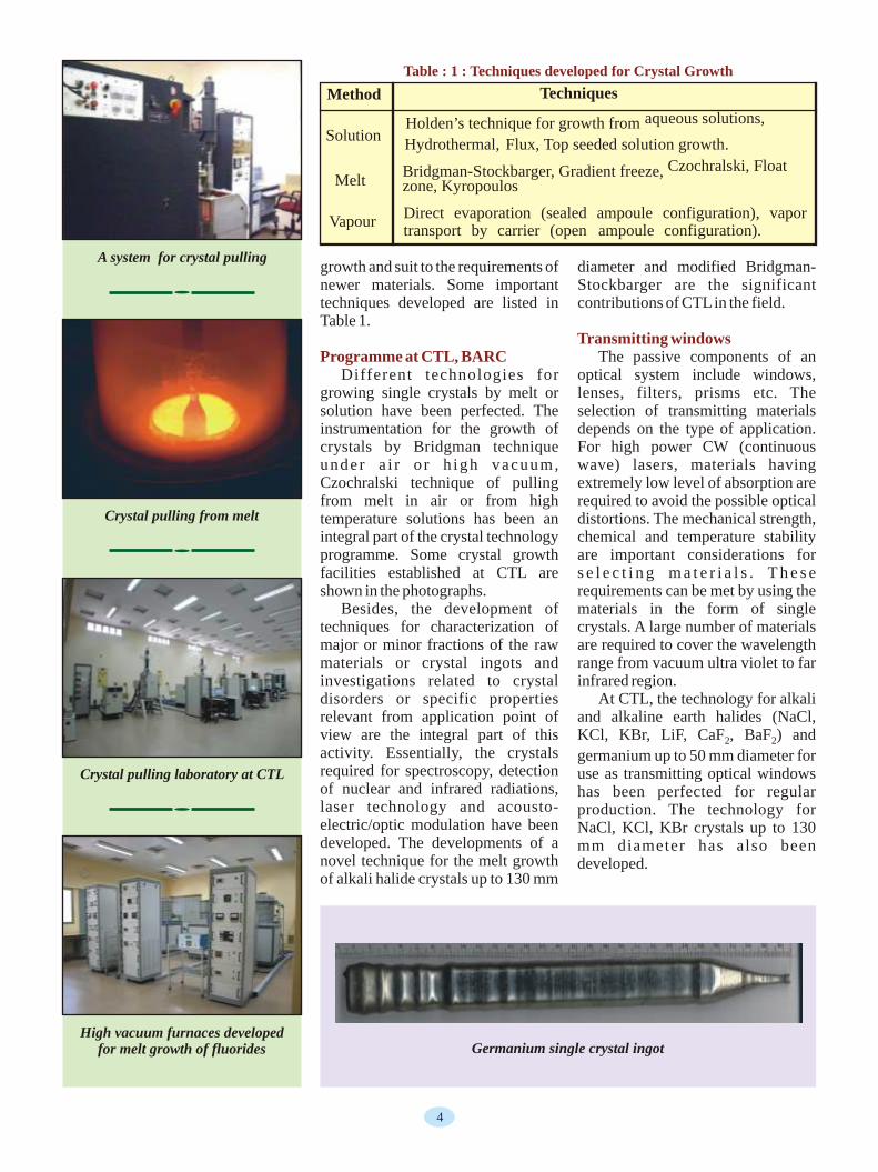
Method Techniques
aqueous solutions, Solution
Holden’s technique for growth from
Hydrothermal, Flux, Top seeded solution growth.
Czochralski, Float
Vapour Direct evaporation (sealed ampoule configuration), vapor transport by carrier (open ampoule configuration).
Table : 1 : Techniques developed for Crystal Growth
Melt Bridgman-Stockbarger, Gradient freeze, zone, Kyropoulos
4

Solid state lasers
Scintillation detectors
Neutron detector
11 -2 -11 x 10 cm s have been developed which could be deployed for ex-vessel power monitoring pressurized water reactors.
A crystalline solid state laser consists of a combination of optically
scintillator is proportional to the energy of the absorbed radiation and Those materials which convert hence the latter can be determined by energy lost by ionizing radiation into measuring the pulse height spectrum. pulses of light are called scintillators. A m o n g o t h e r f a c t o r s , t h e The pulses of light emitted by the transparency of the scintillator to the scintillating material can be detected light emitted on passage of radiation by a sensitive light detector and the is an important requirement from combination of a scintillator and a active impurities in a primarily app l ica t ions po in t o f v iew. light detector is called a scintillation optically passive host. The host Scintillators can be made of a variety detector. The light pulse emitted by a material should be transparent to both of materials, depending on the the pumping and lasing radiations. intended applications. The most Further, it should be possible to common scintillators used in X- or incorporate the desired dopant in the gamma-ray detection are the single lattice and grow crystals in useful crystals of inorganic materials. sizes with excellent optical quality.
The crystals of NaI(Tl), CsI(Tl, For CW or high power repetitive Na), CaF (Eu), BaF , Bi Ge O upto pulsed operation, it is desired that the 2 2 4 3 12
50 mm diameter have been produced material should have low thermal at CTL. R&D work has also been expansion and high thermal carried out on heavy scintillators conductivity. The most suitable including CdWO , PbWO and optically active impurities for wide 4 4
ZnWO . band gap materials are those which 4
have ionic radii comparable to those of the positive ions in the host lattice
Lithium tetra borate (Li B O ) is with the same valence state. 2 4 7
known to be a radiation-resistant Furthermore, their electronic material thus finding application as a transitions must be well shielded tissue equivalent material in radiation from interactions with host lattice. dosimetry. The material suffers The impurity ion also must have a negligible damage on exposure to suitable energy level structure. For fast neutrons and this fact has been low laser emission threshold it is exploited to develop proportional desired that the terminal laser state counter for the measurement of lies higher enough above the ground
9state so that it is not appreciably neutron fluxes over the range 10 to
12 -2 -1 p o p u l a t e d a t t h e o p e r a t i n g 10 cm s . The growth of core free temperatures. transparent crystals of 30 mm dia. x
Among the solid state lasers 20 mm length has been achieved and known, yttrium aluminum garnet the detectors showing sensitivity of
-18 -1 (Y Al O ) with substitution of about 3 5 124 x 10 A (nv) at a flux level of 1% of yttrium with neodymium
LiF ingot NaCl ingot
Crystal scintillators
Bi Ge O4 3 12 PbWO4
CsI(Tl) ZnWO4
Li B O crystal ingot2 4 7
5
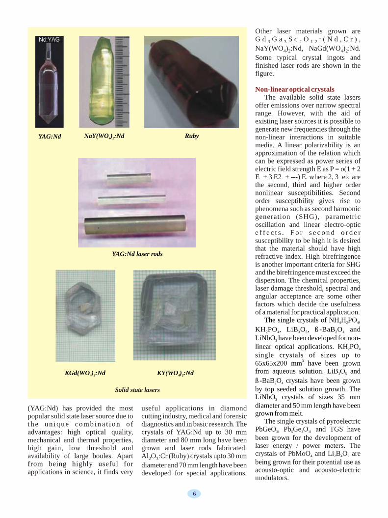
Other laser materials grown are G d G a S c O : ( N d , C r ) , 3 3 2 1 2
NaY(WO ) :Nd, NaGd(WO ) :Nd. 4 2 4 2
Some typical crystal ingots and finished laser rods are shown in the figure.
The available solid state lasers offer emissions over narrow spectral range. However, with the aid of existing laser sources it is possible to generate new frequencies through the non-linear interactions in suitable media. A linear polarizability is an approximation of the relation which can be expressed as power series of electric field strength E as P = o(1 + 2 E + 3 E2 + ---) E. where 2, 3 etc are the second, third and higher order nonlinear susceptibilities. Second order susceptibility gives rise to phenomena such as second harmonic generation (SHG), parametric oscillation and linear electro-optic e f f e c t s . F o r s e c o n d o r d e r susceptibility to be high it is desired that the material should have high refractive index. High birefringence is another important criteria for SHG and the birefringence must exceed the dispersion. The chemical properties, laser damage threshold, spectral and angular acceptance are some other factors which decide the usefulness of a material for practical application.
(YAG:Nd) has provided the most useful applications in diamond popular solid state laser source due to cutting industry, medical and forensic
The single crystals of pyroelectric t h e u n i q u e c o m b i n a t i o n o f diagnostics and in basic research. The PbGeO , Pb Ge O and TGS have 3 5 3 11advantages: high optical quality, crystals of YAG:Nd up to 30 mm been grown for the development of mechanical and thermal properties, diameter and 80 mm long have been laser energy / power meters. The high gain, low threshold and grown and laser rods fabricated. crystals of PbMoO and Li B O are 4 2 4 7availability of large boules. Apart Al O :Cr (Ruby) crystals upto 30 mm 2 3being grown for their potential use as from being highly useful for diameter and 70 mm length have been acousto-optic and acousto-electric applications in science, it finds very developed for special applications. modulators.
Non-linear optical crystals
The single crystals of NH H PO , 4 2 4
KH PO , LiB O , ß-BaB O and 2 4 3 5 2 4
LiNbO have been developed for non-3
linear optical applications. KH PO 2 4
single crystals of sizes up to 3
65x65x200 mm have been grown from aqueous solution. LiB O and 3 5
ß-BaB O crystals have been grown 2 4
by top seeded solution growth. The LiNbO crystals of sizes 35 mm 3
diameter and 50 mm length have been grown from melt.
NaY(WO ) :Nd4 2YAG:Nd Ruby
YAG:Nd laser rods
KGd(WO ) :Nd4 2 KY(WO ) :Nd4 2
Solid state lasers
6

Crystal characterization
UV excited luminescence from crystals
The detection of minute amount of deviations from stoichiometry in optical crystals, the role of microstructure of the melt/solution in crystallization process and the r e l a t i o n s h i p b e t w e e n n o n -stoichiometry and crystal cracking are some of the crucial issues that have been addressed in some detail at CTL. The investigations related to the fluorescence and scintillation emissions from crystals are also pursued.
The vision is to mature the technology of crystal growth for the materials needed in research and applications as lasers, radiation detectors and electronics.
Non-linear Optical crystals
KH PO2 4 LiNbO3 LiB O3 5 TGS
PbMoO4 PbGeO3 Pb Ge O5 3 11
UV excited luminescence from crystals
7

niobium-titanium superconducting India's accelerator pioneers began The PMD was a great success, wire. Hunting for a suitable company to build the Calcutta cyclotron in the unprecedented in modern India, to build our cryostat was an early 1970s but soon found that the particularly on this scale. It required adventure. We searched all of India, industrial infrastructure was not all kinds of creative innovation, with but drew a blank. Despite our geared up to provide the necessary the best suggestions coming from the determination we failed to find a level of technology. They had, for youngest members of the team. suitable company to built the instance, difficulty in finding a Almost overnight, India became a cryostat, and eventually turned to Air suitable manufacturer for the key player on the world stage in this Liquide, France, but not without essential resonator tank. The Garden field. This kind of science and the hiccups. We learned how to mange Reach Ship Builders said, they could associated precision technology large-scale liquid helium and build watertight ships but had no which had so far remained dormant, maintain a steady liquid helium experience in making tanks that had began to flourish; there was no temperature.to be airtight, maintaining a high looking back.
-6 Finally, on 11 January 2005, the The PMD later went through a vacuum (10 torr). But build it, they magnet became superconducting at a basics design change with the did , and the cyclotron was temperature of around 4.2 K and introduction of a “honeycomb” commissioned in June 1977. It is still maintained the superconducting state design, and it was shipped across the working well and has catered to for months. It was a fantastic Atlantic for the STAR experiment at a l m o s t t w o g e n e r a t i o n s o f experience. All of January felt like a RHIC at the Brookhaven National experimental nuclear physicists.carnival. We had made the leap from Laboratory. With a reputation already In the early 1980s some of us room-temperature technology to established at CERN, entry into wanted to build a detector to be used large-scale cryogenic technology.RHIC posed no problem whatsoever. at CERN's SPS to register photons as
The PMD had already accumulated a Meanwhile at CERN the LHC signals of quark-gluon plasma vast quantity of data at RHIC, with was looming large on the horizon, (QGP), formed in the collision of two good statistics. Complemented by the with a heavy-ion programme and the nuclei at laboratory energies of results from the PHENIX detector, ALICE detector. We were thrilled typically 200GeV/nucleon. The photons look promising as signals of here was scope for the old workhorse, protons and neutrons of an atomic QGP. the PMD, in a more sophisticated nucleus at this energy should “melt”
guise. Aligarh Muslim University Meanwhile, in India we moved into their fundamental constituents, and IIT-Bombay, also joined in our from the room-temperature cyclotron the quarks and gluons, rather as in the
to a superconducting cyclotron using quest. My colleagues at Saha Institute p r i m o r d i a l u n i v e r s e a f e w microseconds after the Big Bang.
The adventure of building a photon multiplicity detector (PMD) was inspiring but not easy. The sheer size and complexity was daunting; the required precision even more so.
We did the design in India. The Cyclotron Centre in Calcutta: the Institute of Physics in Bhubaneswar, the universities of Rajasthan and Jammu, and Panjab University joined in. In a short time the group built the PMD with 55,000 pads, each
2consisting of a 1-2 cm plastic scintillator. Optical fibres inserted diagonally in each pad picked up the photons, the possible signals of QGP.
An Indian Dream Come TrueBikash Sinha
Director, Variable Energy Cyclotron Centre, Kolkata, and Director, Saha Institute of Nuclear Physics, Kolkata
8

went further, and wanted to participate in the d imuon spec t romete r Colleagues who had remained dormant or busy with routine jobs, were suddenly inspired. They went on to design the MANAS chip for the muon arm. An Indian company, the Semi-Conductor Complex Ltd. in Chandigarh, enthusiastically offered to build the hardware. After much debate the MANAS chip became central to the ALICE muon arm and was accepted worldwide.
Last time at CERN, walking in the shadow of ALICE, marveling at its size and the immaculate precision with which the work was done, I felt like Alice in Wonderland with “quarkland” beckoning on the horizon.
In the 1970s, India was still a spectator in the world theatre of high science. Individuals who migrated to other parts of the world sometimes excelled . In India, people were proud of them but remained convinced that such feats could not be accomplished back home. In the 1980s, however, there was a major paradigm shift in our mind set. We began to dream of competing with the world from India.
By the beginning of the 21st century, India was no longer a spectator but a significant player on the world stage. The glamour of individual excellence had been replaced by the wisdom of collective effort. We had turned mature and ambitious. What I have presented is a chronicle of that evolution. I am proud and grateful to be a witness and indeed a participant in this evolving panorama.
The voyage that started almost 30 years ago continues with resolve from LHC to FAIR to an ILC and further, making the impossible possible and turning dreams to reality.
BARC's Experimental Facility for the Study of different Core Lattices
Attains Criticality
A low power Critical Facility at BARC, Trombay attained first criticality at 1900 hrs on Monday, April 7, 2008. This Critical Facility is a versatile research platform designed to facilitate the study of different core lattices based on various fuel types, different moderator materials and reactivity control devices.
BARC is developing a 300 MWe Advanced Heavy Water Reactor (AHWR) which, in its equilibrium condition, will derive two-third of its energy from thorium based fuel. AHWR will serve as a technology demonstrator to facilitate development of several enabling technologies for large scale thorium utilisation in the third stage of Indian Nuclear Power Programme. The first-of-a-kind reactor core configuration of AHWR will be progressively simulated in this Critical Facility, which is equipped with state-of-art nuclear instrumentation. Optimisation of physics design of AHWR and generation of additional nuclear data relevant to the design of thorium based advanced reactor will be the main research programme for this Critical Facility, which also offers flexibility to suit the core configuration of future Pressurised Heavy Water and Light Water Reactors.
BARC is currently building a 20 MeV proton accelerator, which will be used for generating neutrons. It is contemplated to couple the Critical Facility with this external neutron source for carrying out some early studies on the reactor physics aspects of Accelerator Driven Sub-Critical reactor systems.
MANAS Chip
9

M a s s s p e c t r o m e t r y h a s spectrometers for 1) heavy water temperature controlled inlet system is established itself as a matured and analysis in Heavy Water Plants, and expected to result in improved reliable analytical tool for a variety of 2) process gas analysis in Rare Metals precision and sample throughput.applications in the field of analytical Plant (RMP), Mysore, (II) thermal b) Process Gas analysis: Two sciences in general and nuclear ionization mass spectrometers magnetic sector instruments were technology in particular. The features (TIMS) for 1) RMP, Mysore, 2) delivered to RMP, Mysore, for high offered by mass spectrometers viz. reprocessing plants at KARP, precision isotope ratio analysis of the h igh sens i t iv i ty, speci f ic i ty, Kalpakkam and AFFF, Tarapur, and process gas viz., UF , during late 6
selectivity, versatility, high precision 3) Chemical Engineering Division, 1980s to early '90s. Recently the a n d a c c u r a c y, m a k e t h e m BARC, (III) twin ion source mass electronics in these machines has indispensable for applications in spectrometer for boron and oxygen been upgraded to extend the useful n u c l e a r t e c h n o l o g y. M a s s isotopic analysis for enrichment plant life of these instruments. Two more spectrometers have routinely been at Heavy Water Plants, Talcher, and similar instruments have been used at various stages of nuclear fuel (IV) quadrupole mass spectrometers delivered in the recent past. The cycle starting from ore exploration to (QMS) for compositional analysis for instrumental features of these f u e l f a b r i c a t i o n , f u e l CCCM, Hydrabad , and (V) instruments are listed in Table 2.character izat ion, enr ichment , inductively coupled plasma mass reprocessing, and wastemanagement. spectrometers (ICPMS) for isotopic Mass spectrometric techniques have and multi-element analysis for use in been successfully applied to the the boron enrichment facility at BARC has developed several measurement of fission gas products Heavy Water Plant, Manuguru. TIMS instruments for high precision in a nuclear reactor. Under X plan an advanced version of isotope ratio measurement in solid
Realising the importance of mass a five collector, 12 stage turret TIMS samples like Lithium, Boron, spectrometric techniques in nuclear for U & Pu isotopic analysis has also Rubidium/Strontium, Uranium and areas, BARC, as early as 1954, been built. Brief details are given Plutonium. Some of the important initiated the programme on the below. parameters of these instrument are development of mass spectrometers given in Table 3.as part of its instrument development program. Over the years, expertise a) D/H analysis: Because of the has been developed in the areas of use of heavy water as moderator in high vacuum (HV) / ultra high our nuclear power reactors, initial Considering the growing demand vacuum (UHV) technology, precision mass spectrometry activity related to in DAE for TIMS for isotope ratio mechanica l eng ineer ing and the development of D/H ratio analysis with improved sensitivity fabrication, magnet technology, ion i n s t r u m e n t s . S i x t e e n s u c h and better precision, a new TIMS has optics, sensitive and ultra stable instruments, Fig (1), have been built been developed under X plan. Some analog, digital and RF electronics, so far and supplied to various plants of the important specifications are as data systems etc. During the last of Heavy Water Board and Heavy follows: decade or so there has been Water Division, BARC. Salient significant improvement in the features of this instrument are listed Ion accelerating voltage : up to 10 performance of mass spectrometers in Table 1. kV (8 kV normal working)developed inhouse especially those of These instruments have served Resolution : 450the isotope ratio types, built for gas very well in various applications Sensitivity : one ion for 580 atoms of and solid sample analysis, and especially in all the Heavy Water uraniumquadrupole based inductively Plants. However, to meet the Abundance sensitivity : 25 ppm at coupled plasma mass spectrometer demands of higher accuracy and mass 238 amu with two stage einzel built for isotopic and trace element better precision (< 1 ppm) in ratio lens systemanalysis. measurement, a computer controlled Mass Range : 1 to 800amu
Some of the instruments that have sample inlet system is presently No. of collectors : Fivebeen built include (I) gas source mass under development. This new
T h e r m a l I o n i s a t i o n M a s s Spectrometers (TIMS)
Gas Source Mass Spectrometers
T I M S w i t h i m p r o v e d specifications
Indigenous Development of Mass Spectrometers for Analytical Applications in Nuclear Technology
V.K.Handu and V. C. SahniBhabha Atomic Research Centre, Trombay, Mumbai-400085
10
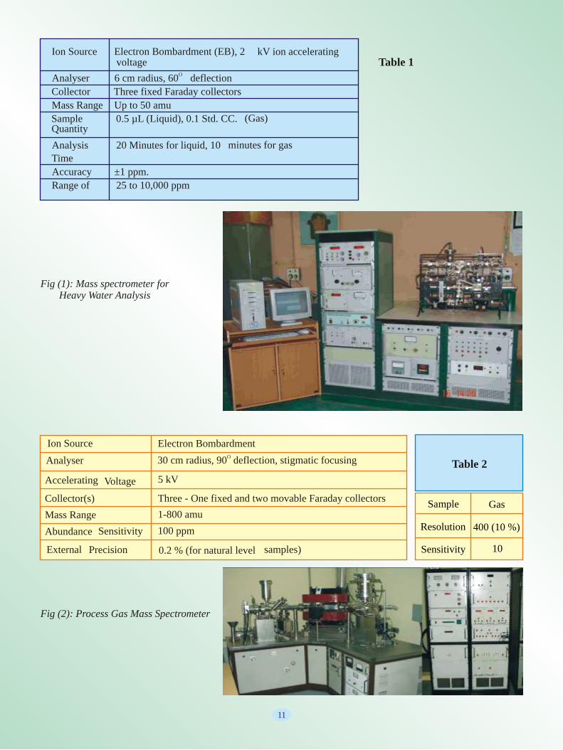
Table 1 Ion Source Electron Bombardment (EB), 2 kV ion accelerating
voltageO
Analyser 6 cm radius, 60 deflection
Collector Three fixed Faraday collectors
Mass Range Up to 50 amu
Sample Quantity
0.5 µL (Liquid), 0.1 Std. CC. (Gas)
Analysis
Time
20 Minutes for liquid, 10 minutes for gas
Accuracy ±1 ppm.
Range of 25 to 10,000 ppm
Fig (1): Mass spectrometer for Heavy Water Analysis
Sample
Resolution
Sensitivity
Gas
400 (10 %)
10
Ion Source
Analyser
Accelerating Voltage 5 kV
Collector(s)
Mass Range
Abundance Sensitivity 100 ppm
External Precision 0.2 % (for natural level samples)
O30 cm radius, 90 deflection, stigmatic focusing
Electron Bombardment
Three - One fixed and two movable Faraday collectors
1-800 amu
Table 2
Fig (2): Process Gas Mass Spectrometer
11
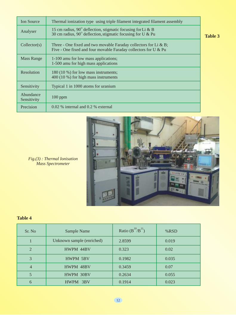
Ion Source Thermal ionization type using triple filament integrated filament assembly
1-100 amu for low mass applications; 1-500 amu for high mass applications
O 15 cm radius, 90 deflection, stigmatic focusing forLi & B
180 (10 %) for low mass instruments;400 (10 %) for high mass instruments
Typical 1 in 1000 atoms for uranium
100 ppm
Three - One fixed and two movable Faraday collectors for Li & B;Five - One fixed and four movable Faraday collectors for U & Pu
Collector(s)
Mass Range
Analyser O 30 cm radius, 90 deflection, stigmatic focusing for U & Pu
Resolution
Sensitivity
Abundance Sensitivity
Precision 0.02 % internal and 0.2 % external
Sr. No %RSD10 11
Ratio (B /B )Sample Name
Unknown sample (enriched)
HWPM 44BV
2.8599
0.323
0.1982
0.3459
0.2634
0.1914
0.019
0.02
0.035
0.07
0.055
0.023
HWPM 5BV
HWPM 48BV
HWPM 30BV
HWPM 3BV
1
2
3
4
5
6
Table 3
Table 4
12
Fig.(3) : Thermal Ionisation Mass Spectrometer
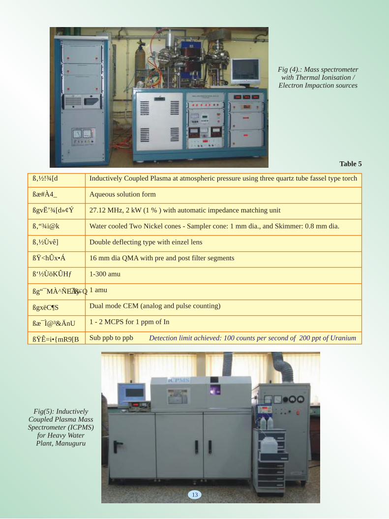
Fig (4).: Mass spectrometer with Thermal Ionisation /
Electron Impaction sources
Table 5
Fig(5): Inductively Coupled Plasma Mass Spectrometer (ICPMS)
for Heavy Water Plant, Manuguru
ß‚�½�!¾[ d
ßæ�#À4_
ßgvË’¾[�d»¢Ý
ß‚�“¾i�@k
ß‚�½�Ùvê]�
ߟ<hÛx•Á
ß‘½ÙöKÛ Hƒ
ßg“¯MÀ^ÑEÄÿ¨Q⇓ß»
ßg�xë�C¶S
ßæ�¯Ì@³&ÄnU
ߟÊ=i•�{�m�R9[B
Inductively Coupled Plasma at atmospheric pressure using three quartz tube fassel type torch
Aqueous solution form
27.12 MHz, 2 kW (1 % ) with automatic impedance matching unit
Water cooled Two Nickel cones - Sampler cone: 1 mm dia., and Skimmer: 0.8 mm dia.
Double deflecting type with einzel lens
16 mm dia QMA with pre and post filter segments
1-300 amu
1 amu
Dual mode CEM (analog and pulse counting)
1 - 2 MCPS for 1 ppm of In
Sub ppb to ppb Detection limit achieved: 100 counts per second of 200 ppt of Uranium
13
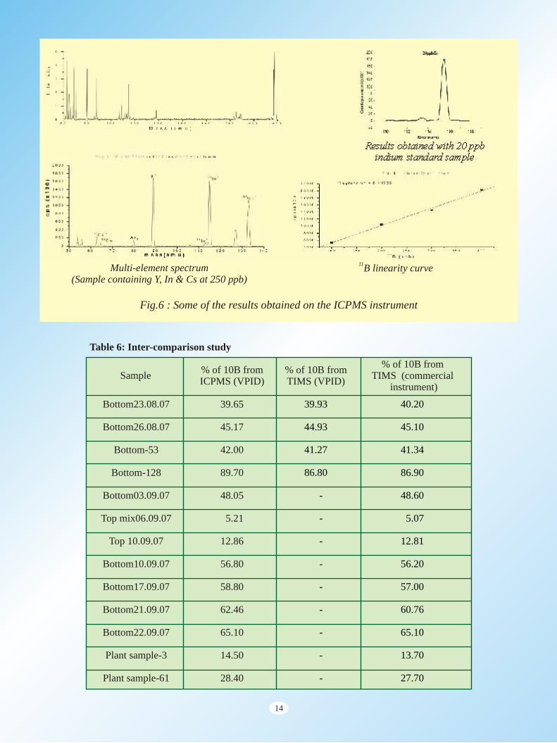
11B linearity curve
Fig.6 : Some of the results obtained on the ICPMS instrument
Multi-element spectrum(Sample containing Y, In & Cs at 250 ppb)
Results obtained with 20 ppb indium standard sample
39.65
45.17
42.00
89.70
48.05
5.21
12.86
56.80
58.80
62.46
65.10
14.50
28.40
39.93
44.93
41.27
86.80
-
-
-
-
-
-
-
-
-
40.20
45.10
41.34
86.90
48.60
5.07
12.81
56.20
57.00
60.76
65.10
13.70
27.70
Bottom23.08.07
Bottom26.08.07
Bottom-53
Bottom-128
Bottom03.09.07
Top mix06.09.07
Top 10.09.07
Bottom10.09.07
Bottom17.09.07
Bottom21.09.07
Bottom22.09.07
Plant sample-3
Plant sample-61
% of 10B from TIMS (commercial
instrument)Sample
% of 10B from ICPMS (VPID)
% of 10B from TIMS (VPID)
Table 6: Inter-comparison study
14
FC/CEM
-31 x 10
1
0.5 to 1 amu
1 - 50 ppm
Rod Diameter (mm)
Rod Length (mm)
Pre & Post filter length (mm)
Collector
Sensitivity (Amp/Torr) i) Faraday Cup ii) Multiplier
Mass Range (amu)
Resolution ( m) (variable)
Abundance Sensitivity
⇓
Parameters
19
225
27
QMS-19
16
200
24
QMS-16
450 300
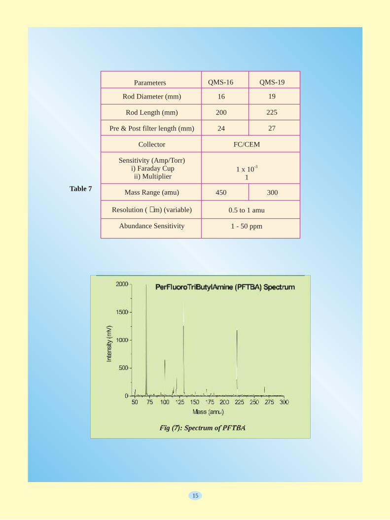
Fig (7): Spectrum of PFTBA
Table 7
15

16
Material from this or any issue of Nuclear
India may be reproduced on request.
Precision (internal) : 0.02% modes have all been developed in diameters have been successfully house and integrated into a prototype deve loped . The des ign and Precision (external) : 0.1% for ICPMS. It offers a sensitivity of performance details of these natural and depleted Uranium; 0.07% 1 MCPS per ppm and LODs of a few instruments are listed Table 7. Fig (7) for U500 samples.ppb for most of the elements. The shows a typical spectrum obtained on Other facilities : Magnetic field design specifications of this a 16mm QMS with PFTBA - a regulation, 12 stage Turret, Lab-instrument are listed in Table 5. calibration standard. The spectrum view based software for control and Subsequently, first engineered model clearly shows the mass range, data acquisition. of the ICPMS has been developed for resolution and relative sensitivities A comparison study with a isotopic and trace element analysis of for constituent peaks. commerc ia l i n s t rumen t was boron. This ICPMS, shown in Fig (5), One such QMS, based on 19mm conducted, in association with FCD, will shortly be installed at Heavy rod assembly, was developed and BARC to check the performance of Water Plant, Manuguru. installed in a Resonance Ionisation this TIMS. The ratios obtained and
Mass Spectrometry (RIMS) being RSD are matching well with those developed at NCCCM, Hyderabad. Inter-comparison study: Table 6 obtained in the imported instrument, Technology of this instrument is s h o w s t h e r e s u l t s o f a n validating the usability of this ready for transfer to industry for intercomparison study that was instrument for similar applications.commercial exploitation.carried out on this ICPMS, VPID
TIMS for Boron analysis: A twin developed TIMS and a commercially ion source, triple collector mass bought TIMS available in BARC. spectrometer, Fig (4), has been Samples used were obtained from Instrument development is an developed and installed recently at Boron Enrichment Facility, Heavy ongoing activity at VPID, BARC and Heavy Water Plant, Talcher. Using Water Plant, Manuguru. As can be all efforts are concentrated on electron impact (EI) source, it can seen, the results are matching well developing instruments that, by and
16 18 within acceptable limits. This gives large, fulfill the requirements of the analyse oxygen isotopes O & O the confidence to the users to use this user departments in DAE. Mass and using thermal ionization (TI) indigenous instrument for boron 10 11 spectrometers covering a wide
source, it can analyse B and B isotope ratio and concentration spectrum of inorganic applications isotopes. Change over from TI source measurements. have been successfully designed and to EI source can be accomplished in
developed and accepted by all the about 30 minutes. Table 4 shows the
Multi collector-ICPMS (MC- users. The availability of all the results of the boron samples from
ICPMS): With the expertise gained instruments delivered so far has been Heavy Water Board. Presently this
in development of magnetic sector reported to be > 90%. Development mass spectrometer is being used for
instruments and plasma ion sources, of advanced technology instruments, isotopic analysis of boron in boron
design of a double focusing MC- like MC-ICPMS, is taken up to enrichment facility.
ICPMS using electrostatic and enhance our capabilities and also magnetic sector analyzers has been meet the future requirements of completed. Some of the parts have analytical community. Two TIMS been received and are undergoing in s t rumen t s a r e a l so unde r testing. This instrument will be used, development for AMD, Hydrabad
BARC took up the development along with TIMS, for the precise and BARC for the isotopic analysis of
of a quadrupole mass analyzer based isotopic and trace analysis of nuclear Rb/Sr to U/Th (including Os) for
ICPMS, initially with DST support, materials. geochronological studies.
in order to explore the potential of deve lop ing t h i s t e chno logy indigenously. All the subsystems viz. differentially pumped vacuum
This development was taken up, system, RF ( 2,5 kW @ 27.12 MHz), initially, to support ICPMS program impedance matching electronics, in making it fully indigenous. QMS sampler and skimmer cones, ion systems with electron bombardment optical potentials, precision RF (300 type ion source suitable for watts @ 1,2 MHz) and DC supplies gas/volatile liquid samples, and for QMA, and data acquisition employing 16 mm / 19mm rod system in analog and pulse counting
Conclusions
Inductively Coupled Plasma Source Mass Spectrometer (ICPMS)
Quadrupole mass spectrometer (QMS)

DAE and University Institute of Chemical Technology, Mumbai to establish a new
DAE-UICT Centre for Chemical Engineering Education and Research
17
In the 21st century, where knowledge economy propels a nation, higher education is the major contributor to the economic growth of the country. In India the number of Engineering Technology Ph.D.'s per year 1,000,000 persons is 0.8, which is much smaller compared to other developed countries; for example, the number is 33 in Japan, 30 in the USA and 3 in China. Further, the number of Ph.Ds in Engineering and Technology is dismally small compared to that in Basic Sciences. The number of Ph.D.s that is directly proportional to the GDP of the country needs to be enhanced to 3000. There is indeed a wide gap to be filled up.
The other key driver of the economy is the energy production: each rupee invested in the energy sector increases the output by ten to fifteen rupees. Evidently, India has to harness all forms of renewable and non-renewable energy sources to increase its energy production. The massive R&D programme launched by DAE towards design and manufacture of higher capacity power plants and nuclear fuel breeding reactors, commencing the thorium fuel cycle, employing high temperature reactors for direct hydrogen production, and initiating work on the accelerator driven inherently safe nuclear reactor and prototype fusion reactors. These efforts require a pool of talented, motivated and highly qualified personnel: engineers and technologists with deep insight into science, and scientists with competence in engineering to convert research output to technology.
Chemical engineering with a multidisciplinary base has played a major role in shaping the technologies for the nuclear fuel cycle and nuclear reactors, and many advanced energy conversion technologies. University Institute of Chemical Technology, Mumbai (UICT) is one of the foremost academic institutions in India with a proven track record in training high quality manpower and in conducting research in Chemical Engineering and Technology. While UICT is a major resource institution in terms of technology development and fundamental research at the cutting edge on the global scale, DAE's Bhabha Atomic Research Centre and Indira Gandhi Centre of Atomic Research have demonstrated over decades their ability to conduct multi-disciplinary, mission oriented R&D leading to a large number of indigenous and innovative chemical engineering processes, equipment and instruments, and technologies.
On March 13, 2008, DAE and UICT have signed a memorandum of understanding to establish a new Centre for Chemical Engineering, Education and Research to impart education at the Ph.D. level, where interdisciplinary character of Chemical Engineering Education is the essence. With an annual intake of 20 Ph. D. students per year from various streams, the Centre will support 100 Ph. D. students, all engaged in research in the energy sector This scheme will also provide opportunity to the young research scholars, who will be trained with broad based curricula covering basic sciences and chemical engineering, to carry out their experiments in the state of the art laboratories of QAE institutes, especially of BARC and IGCAR.
This Centre will also boost the Collaborative Research Programme between DAE institutions and UICT, by adding in a major way to the existing research projects commissioned through the Board of Nuclear Sciences and the Centre for Knowledge Based Engineering (CKBE). Many of the DAE funded projects have been successfully completed. They are in the areas of process simulation of heavy water plants, ion chromatography for zirconium decontamination and recycle, annular centrifugal extractors for efficient solvent extraction, software for non-destructive radiometric investigation of chemical plants, etc.
For the Research Projects under the Centre, the scientists of BARC and IGCAR in consultation with the faculty members of the UICT have identified several advanced topics of research in Chemical Engineering, which will provide understanding of various phenomena, and help in developing novel technologies and in improving the efficiency and reliability of the existing processes.
A new building will be constructed in the existing premises of UICT, which will house teaching laboratories, lecture halls, CAD - CAM laboratory and computer centre, research laboratories, and pilot scale equipment testing facility. The Centre will also support upto six faculty positions. The Centre initially will be funded to the tune of Rs 75 crores by DAE during the XI and XII Five Year Plan periods.
The benefits that will accrue from this centre are manifold. The important ones being several independent research projects will be completed, with deliverables linked with energy programmes; A pool of young talented and dedicated Ph.D. level engineers with a multidisciplinary perspective will be created with a potential to be absorbed in the DAE units. It will provide a platform for interactions between R&D scientists of DAE and academic personnel from UICT. The new knowledge and the technologies generated in the centre is expected to fulfill atleast partially, the urgent need of our country and society in terms of wealth generation and national security in various sectors.

• DAE participated in Symposium on Emerging
Trends in Separation Science and Technology
(SESTEC 2008) held at the Department of
Chemistry, University of Delhi, Delhi during
March 12-14, 2008. An exhibition on the
achievements of DAE in the last five decades was
held parallel to the symposium. Eminent scientists,
technologists, and academicians visited the
pavilion. Students from various academic
institutions in and around Delhi also benefited
from the exhibition.
• The Bangalore Bio 2008, an exhibition
focusing on biotechnology and related fields was
held at Bangalore during April 24-26, 2008. The
event comprised an International Conference,
Exhibition, Country Presentations etc. The
accomplishments of the department in the areas of
biotechnology, agriculture and food processing
were highlighted. The exhibition proved to be an
excellent platform for fruitful interaction with
many private entrepreneurs and local farmers. The
pavilion also attracted several members from the
academic community especially students pursuing
their graduation/post graduation in relevant areas.
Outreach Programmes
18
DAE Exhibition at SESTEC 2008, University of Delhi
Research Centres Public Sector Undertakings Grant-in-Aid Instituteswww.barc.ernet.in www.npcil.org www.tifr.res.inwww.igcar.ernet.in www.bhavini.nic.in www.saha.ac.in
Www.cat.gov.in www.ucil.gov.in www.tatamemorialcentre.comWww.veccal.ernet.in www.irel.gov.in www.mri.ernet.in
www.amd.gov.in www.ecil.co.in www.iopb.res.inwww.imsc.res.in
Industrial units www.plasma.ernet.inwww.heavywaterboard.org Www.aees.gov.inwww.nfc.gov.in/default.htm
www.britatom.gov.in
DAE
LINKS
DAE Exhibition at SESTEC 2008, University of Delhi

