a unit cost and construction specification framework for ...a unit cost and construction...
TRANSCRIPT

Technical Report Documentation Page 1. Report No. FHWA/TX-07/0-4998-1
2. Government Accession No.
3. Recipient's Catalog No. 5. Report Date October 2006 Published: March 2007
4. Title and Subtitle A UNIT COST AND CONSTRUCTION SPECIFICATION FRAMEWORK FOR UTILITY INSTALLATIONS
6. Performing Organization Code
7. Author(s) Cesar Quiroga, Stanley Kranc, David Ford, Edgar Kraus, and Timothy Taylor
8. Performing Organization Report No. Report 0-4998-1
10. Work Unit No. (TRAIS)
9. Performing Organization Name and Address Texas Transportation Institute The Texas A&M University System College Station, Texas 77843-3135
11. Contract or Grant No. Project 0-4998 13. Type of Report and Period Covered Technical Report: September 2004 – August 2006
12. Sponsoring Agency Name and Address Texas Department of Transportation Research and Technology Implementation Office P. O. Box 5080 Austin, Texas 78763-5080
14. Sponsoring Agency Code
15. Supplementary Notes Project performed in cooperation with the Texas Department of Transportation and the Federal Highway Administration. Project Title: Standardization of Special Provisions and Determination of Unit Costs for Utility Installations URL: http://tti.tamu.edu/documents/0-4998-1.pdf 16. Abstract The Utility Accommodation Rules (UAR) prescribe minimums relative to the accommodation, location, installation, adjustment, and maintenance of utility facilities on the state right of way (ROW). The UAR only cover basic requirements, which makes it necessary to rely on additional guidelines, specifications, and special provisions to handle situations that are not covered by the rules. Because of the lack of standard utility installation construction specifications at TxDOT, many different versions of special specifications and special provisions exist around the state. Closely related to the need to standardize construction specifications for utility installations is the need to standardize methodologies and procedures for the determination of utility relocation costs. In practice, utility companies use a variety of ways to submit utility relocation costs for reimbursement. This lack of standardization translates into difficulties such as how to verify the validity of the cost data submitted for reimbursement and how to adequately prepare for audits and other internal and external inquiries. This report summarizes the work completed to develop a prototype framework of construction specification requirements and corresponding unit cost work items for utility installations at TxDOT and recommendations on how to implement that framework in Texas. The report includes a review of utility relocation and reimbursement practices, describes a prototype unit cost structure framework, describes a prototype framework for water and sanitary sewer specifications, discusses utility installation special provisions, and summarizes conclusions and recommendations for implementation. 17. Key Words Utility Accommodation, Utility Relocation, Utility Reimbursement, Unit Costs, Standard Specifications, Special Provisions
18. Distribution Statement No restrictions. This document is available to the public through NTIS: National Technical Information Service Springfield, Virginia 22161 http://www.ntis.gov
19. Security Classif.(of this report) Unclassified
20. Security Classif.(of this page) Unclassified
21. No. of Pages 160
22. Price
Form DOT F 1700.7 (8-72) Reproduction of completed page authorized


A UNIT COST AND CONSTRUCTION SPECIFICATION FRAMEWORK FOR UTILITY INSTALLATIONS
by
Cesar Quiroga, P.E. Associate Research Engineer Texas Transportation Institute
Stanley Kranc, P.E.
Professor Emeritus, Civil and Environmental Engineering University of South Florida
David Ford, P.E.
Associate Professor, Zachry Department of Civil Engineering Texas A&M University
Edgar Kraus, P.E.
Assistant Research Engineer Texas Transportation Institute
and
Timothy Taylor, P.E.
Graduate Research Assistant Texas Transportation Institute
Report 0-4998-1 Project 0-4998
Project Title: Standardization of Special Provisions and Determination of Unit Costs for Utility Installations
Performed in cooperation with the Texas Department of Transportation
and the Federal Highway Administration
October 2006
Published: March 2007
TEXAS TRANSPORTATION INSTITUTE The Texas A&M University System College Station, Texas 77843-3135


v
DISCLAIMER
The contents of this document reflect the views of the authors, who are responsible for the facts and the accuracy of the data presented herein. The contents do not necessarily reflect the official view or policies of the Federal Highway Administration (FHWA) or the Texas Department of Transportation (TxDOT). This document does not constitute a standard, specification, or regulation, nor is it intended for construction, bidding, or permit purposes. The engineer in charge of the project was Cesar Quiroga, P.E. (Texas Registration #84274). The United States Government and the State of Texas do not endorse products or manufacturers. Trade or manufacturers’ names appear herein solely because they are considered essential to the object of this report.

vi
ACKNOWLEDGMENTS
This research was conducted in cooperation with TxDOT and FHWA. The researchers would like to gratefully acknowledge the assistance provided by TxDOT officials, in particular the following:
• Jeff Masek, Houston District (project director); • John Campbell, Right of Way Division (program coordinator); • Peggy Chandler, Design Division; • Gary Ray, formerly at the Houston District; • Jesse Cooper, Right of Way Division; • Tom Yarbrough, Research and Technology Implementation Office; and • Sylvia Medina, Research and Technology Implementation Office.
The researchers would also like to acknowledge the assistance of Charles Stevens and LuAnn Theiss provided during the gathering of district information concerning utility installation special provisions, as well as the assistance of Kellie Billings provided during the review of federal and state utility reimbursement laws and regulations.

vii
TABLE OF CONTENTS
Page
LIST OF FIGURES ....................................................................................................................... ix
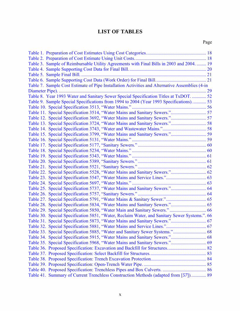
LIST OF TABLES.......................................................................................................................... x
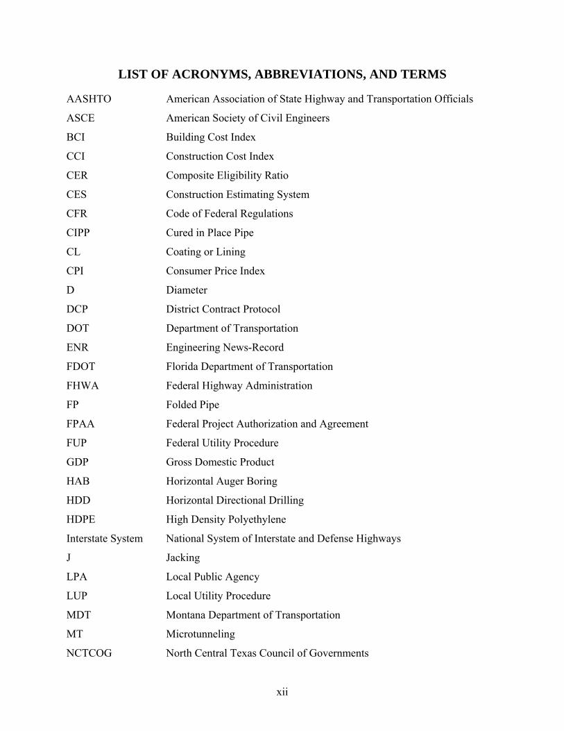
LIST OF ACRONYMS, ABBREVIATIONS, AND TERMS ..................................................... xii
CHAPTER 1. INTRODUCTION .................................................................................................. 1
CHAPTER 2. REVIEW OF UTILITY RELOCATION COSTS.................................................. 3 UTILITY RELOCATION AND REIMBURSEMENT PRACTICES....................................... 3
Federal Codes and Regulations............................................................................................... 3 Texas Codes and Regulations ................................................................................................. 8 Federal Requirements for Utility Relocation Cost Estimates and Billings........................... 10 TxDOT Requirements for Utility Relocation Cost Estimates and Billings.......................... 10
REVIEW OF SAMPLE REIMBURSABLE UTILITY AGREEMENT COST DATA .......... 17 Cost Accounting Detail......................................................................................................... 19 Cost Category and Work Item Consistency of Use .............................................................. 21 Use of Unit Costs .................................................................................................................. 22 Other Issues........................................................................................................................... 22
CHAPTER 3. APPLICABILITY OF THE UNIT COST APPROACH FOR UTILITY RELOCATION WORK................................................................................................................ 25
INTRODUCTION .................................................................................................................... 25 COST ESTIMATION............................................................................................................... 26 STATE PRACTICES REGARDING UNIT COSTS............................................................... 31
Florida ................................................................................................................................... 31 Delaware ............................................................................................................................... 31 Montana ................................................................................................................................ 31 Virginia ................................................................................................................................. 36
UNBALANCED BID ISSUES................................................................................................. 37 UNIT COST STRUCTURE FOR UTILITY RELOCATION WORK AT TxDOT ................ 38
CHAPTER 4. WATER AND SANITARY SEWER SPECIFICATIONS.................................. 51 INTRODUCTION .................................................................................................................... 51 SPECIAL SPECIFICATION SAMPLE................................................................................... 51 SPECIAL SPECIFICATION STYLE ISSUES........................................................................ 53 SPECIAL SPECIFICATION CONTENT, MEASUREMENT, AND PAYMENT ISSUES .. 56 OTHER SPECIFICATION PRACTICES IN TEXAS............................................................. 74 PROPOSED SPECIFICATION FRAMEWORK .................................................................... 75
CHAPTER 5. UTILITY INSTALLATION SPECIAL PROVISIONS..................................... 105 INTRODUCTION .................................................................................................................. 105 UTILITY PERMIT SPECIAL PROVISIONS ....................................................................... 105

viii
Special Provision Analysis ................................................................................................. 106 Analysis............................................................................................................................... 120
UTILITY RELOCATION SPECIAL PROVISIONS ............................................................ 123
CHAPTER 6. CONCLUSIONS AND RECOMMENDATIONS............................................. 127 SUMMARY OF FINDINGS .................................................................................................. 127
Utility Relocation Costs and Reimbursement Practices ..................................................... 127 Utility Installation Construction Specifications.................................................................. 129 Special Provisions............................................................................................................... 131
RECOMMENDATIONS FOR IMPLEMENTATION .......................................................... 132 Utility Relocation Costs and Reimbursement Practices ..................................................... 132 Utility Installation Construction Specifications.................................................................. 133 Special Provisions............................................................................................................... 134 Utility Accommodation Rules ............................................................................................ 135 Training and Dissemination of Information to Stakeholders.............................................. 137
REFERENCES ........................................................................................................................... 141

ix
LIST OF FIGURES
Page Figure 1. Sample Utility Relocation Cost Estimate. .................................................................... 16 Figure 2. Sample Utility Relocation Final Bill. ........................................................................... 17 Figure 3. Water Pipe Cross Section. ............................................................................................ 28 Figure 4. Unit Cost Estimate for Open-Trench Pipe Installation................................................. 30 Figure 5. MDT’s Utility Relocation Cost Management Process. ................................................ 32 Figure 6. Sample Unit Cost Calculation Using MDT Approach. ................................................ 33 Figure 7. Input Data Screen ( 41).................................................................................................. 35 Figure 8. Estimate and Final Bill Selection Screen ( 41).............................................................. 35 Figure 9. Sample Engineer’s Estimate (with Unit Cost-Based Non-Reimbursable Costs). ........ 42 Figure 10. Sample Bid Estimate (with Unit Cost-Based Non-Reimbursable Costs)................... 43 Figure 11. Sample Final Bill (with Unit Cost-Based Non-Reimbursable Costs). ....................... 44 Figure 12. Sample Engineer’s Estimate (with Category-Based Non-Reimbursable Costs). ....... 45 Figure 13. Sample Bid Estimate (with Category-Based Non-Reimbursable Costs). .................. 46 Figure 14. Sample Final Bill (with Category-Based Non-Reimbursable Costs). ........................ 47 Figure 15. Typical Styles of Water Main and Sanitary Sewer Special Specifications (1993 Specifications)............................................................................................................................... 55 Figure 16. Drainage-Related Standard Specifications—Year 1993 Specifications..................... 76 Figure 17. Drainage-Related Standard Specifications—Year 2004 Specifications..................... 77 Figure 18. Proposed Water Installation Specification Framework.............................................. 79 Figure 19. Proposed Sanitary Sewer Specification Framework. ................................................. 80 Figure 20. Proposed Drainage-Related Specification Framework. ............................................. 81
x
LIST OF TABLES
Page
Table 1. Preparation of Cost Estimates Using Cost Categories................................................... 18 Table 2. Preparation of Cost Estimate Using Unit Costs............................................................. 18 Table 3. Sample of Reimbursable Utility Agreements with Final Bills in 2003 and 2004. ........ 19 Table 4. Sample Supporting Cost Data for Final Bill. ................................................................. 20 Table 5. Sample Final Bill. .......................................................................................................... 21 Table 6. Sample Supporting Cost Data (Work Order) for Final Bill........................................... 21 Table 7. Sample Cost Estimate of Pipe Installation Activities and Alternative Assemblies (4-in Diameter Pipe). ............................................................................................................................. 29 Table 8. Year 1993 Water and Sanitary Sewer Special Specification Titles at TxDOT. ............ 52 Table 9. Sample Special Specifications from 1994 to 2004 (Year 1993 Specifications). ........... 53 Table 10. Special Specification 3513, “Water Mains.” ............................................................... 56 Table 11. Special Specification 3514, “Water Mains and Sanitary Sewers.”.............................. 57 Table 12. Special Specification 3692, “Water Mains and Sanitary Sewers.”.............................. 57 Table 13. Special Specification 3724, “Water Mains and Sanitary Sewers.”.............................. 58 Table 14. Special Specification 3743, “Water and Wastewater Mains.”..................................... 58 Table 15. Special Specification 3799, “Water Mains and Sanitary Sewers.”.............................. 59 Table 16. Special Specification 5131, “Water Mains.” ............................................................... 59 Table 17. Special Specification 5177, “Sanitary Sewers.” .......................................................... 60 Table 18. Special Specification 5234, “Water Mains.” ............................................................... 60 Table 19. Special Specification 5343, “Water Mains.” ............................................................... 61 Table 20. Special Specification 5389, “Sanitary Sewers.” .......................................................... 61 Table 21. Special Specification 5521, “Sanitary Sewers.” .......................................................... 62 Table 22. Special Specification 5528, “Water Mains and Sanitary Sewers.”.............................. 62 Table 23. Special Specification 5547, “Water Mains and Service Lines.”.................................. 63 Table 24. Special Specification 5697, “Water Mains.” ............................................................... 63 Table 25. Special Specification 5737, “Water Mains and Sanitary Sewers.”.............................. 64 Table 26. Special Specification 5757, “Sanitary Sewers.” .......................................................... 64 Table 27. Special Specification 5791, “Water Mains & Sanitary Sewer.”.................................. 65 Table 28. Special Specification 5834, “Water Mains and Sanitary Sewers.”.............................. 65 Table 29. Special Specification 5850, “Water Main and Sanitary Sewers.” ............................... 66 Table 30. Special Specification 5851, “Water, Reclaim Water, and Sanitary Sewer Systems.”. 66 Table 31. Special Specification 5873, “Water Mains and Sanitary Sewers.”.............................. 67 Table 32. Special Specification 5881, “Water Mains and Service Lines.”.................................. 67 Table 33. Special Specification 5885, “Water and Sanitary Sewer Systems.”............................ 68 Table 34. Special Specification 5915, “Water Mains and Sanitary Sewers.”.............................. 68 Table 35. Special Specification 5968, “Water Mains and Sanitary Sewers.”.............................. 69 Table 36. Proposed Specification: Excavation and Backfill for Structures................................. 82 Table 37. Proposed Specification: Select Backfill for Structures................................................ 83 Table 38. Proposed Specification: Trench Excavation Protection............................................... 84 Table 39. Proposed Specification: Open-Trench Water Pipe. ..................................................... 85 Table 40. Proposed Specification: Trenchless Pipes and Box Culverts. ..................................... 86 Table 41. Summary of Current Trenchless Construction Methods (adapted from [ 57])............. 89

xi
Table 42. Summary of Current Trenchless Renewal Methods (adapted from [ 57]). .................. 91 Table 43. Proposed Specification: Open-Trench Pipe Encasement............................................. 93 Table 44. Proposed Specification: Adjusting or Relocating Water Pipes. .................................. 94 Table 45. Proposed Specification: Water Appurtenances............................................................ 95 Table 46. Proposed Specification: Adjusting or Relocating Pipe Appurtenances....................... 96 Table 47. Proposed Specification: Manholes and Inlets. ............................................................. 98 Table 48. Proposed Specification: Removing Structures. ........................................................... 99 Table 49. Proposed Specification: Abandoning Structures. ...................................................... 100 Table 50. Proposed Specification: Open-Trench Gravity Sanitary Sewer Pipe. ....................... 101 Table 51. Proposed Specification: Open-Trench Pressure Sanitary Sewer Pipe. ...................... 102 Table 52. Proposed Specification: Adjusting or Relocating Sanitary Sewer Pipes. .................. 103 Table 53. Proposed Specification: Sanitary Sewer Appurtenances. .......................................... 104
xii
LIST OF ACRONYMS, ABBREVIATIONS, AND TERMS
AASHTO American Association of State Highway and Transportation Officials
ASCE American Society of Civil Engineers
BCI Building Cost Index
CCI Construction Cost Index
CER Composite Eligibility Ratio
CES Construction Estimating System
CFR Code of Federal Regulations
CIPP Cured in Place Pipe
CL Coating or Lining
CPI Consumer Price Index
D Diameter
DCP District Contract Protocol
DOT Department of Transportation
ENR Engineering News-Record
FDOT Florida Department of Transportation
FHWA Federal Highway Administration
FP Folded Pipe
FPAA Federal Project Authorization and Agreement
FUP Federal Utility Procedure
GDP Gross Domestic Product
HAB Horizontal Auger Boring
HDD Horizontal Directional Drilling
HDPE High Density Polyethylene
Interstate System National System of Interstate and Defense Highways
J Jacking
LPA Local Public Agency
LUP Local Utility Procedure
MDT Montana Department of Transportation
MT Microtunneling
NCTCOG North Central Texas Council of Governments
xiii
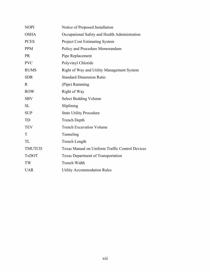
NOPI Notice of Proposed Installation
OSHA Occupational Safety and Health Administration
PCES Project Cost Estimating System
PPM Policy and Procedure Memorandum
PR Pipe Replacement
PVC Polyvinyl Chloride
RUMS Right of Way and Utility Management System
SDR Standard Dimension Ratio
R (Pipe) Ramming
ROW Right of Way
SBV Select Bedding Volume
SL Sliplining
SUP State Utility Procedure
TD Trench Depth
TEV Trench Excavation Volume
T Tunneling
TL Trench Length
TMUTCD Texas Manual on Uniform Traffic Control Devices
TxDOT Texas Department of Transportation
TW Trench Width
UAR Utility Accommodation Rules

1
CHAPTER 1. INTRODUCTION
The Utility Accommodation Rules (UAR) prescribe minimums relative to the accommodation, location, installation, adjustment, and maintenance of utility facilities on the state right of way (ROW) ( 1). The UAR only cover basic requirements, which makes it necessary to rely on additional guidelines, specifications, and special provisions to handle situations that are not covered by the rules. Because of the lack of standard utility installation construction specifications at TxDOT, many different versions of special specifications and special provisions—frequently containing similar information—exist around the state. There is a need to modernize and standardize construction specifications for utility installations at TxDOT. The need is critical as the number of utility facilities allowed within the state ROW, many of them spanning district boundaries, continues to increase. Closely related to the need to standardize construction specifications for utility installations is the need to standardize methodologies and procedures for the determination of utility relocation costs. According to the TxDOT Utility Manual, utility relocation cost estimates need to identify the items of work to be performed, as broken down into categories such as materials, labor, overhead, transportation and equipment, traffic control, betterments, and miscellaneous ( 2). In practice, there is a wide range of ways in which utility companies submit utility relocation costs for reimbursement. In addition, this cost structure is not backed by a corresponding set of specifications that could facilitate inspections in the field. This lack of standardization translates into difficulties such as how to verify the validity of the cost data provided by utility companies and how to adequately prepare for audits and other internal and external inquiries. There is a need to review existing utility relocation cost data and develop a standardized procedure and corresponding listing of unit cost work items for utility installations within the ROW. This report summarizes the work the researchers completed to develop a prototype framework of construction specification requirements—structured to provide improved unit cost comparisons—and corresponding unit cost work items for utility installations at TxDOT, along with recommendations on how to implement that framework in Texas. The report is organized as follows:
• Chapter 1 is this introductory chapter. • Chapter 2 provides a review of utility relocation and reimbursement practices. • Chapter 3 describes the applicability of the unit cost approach for utility relocation work
and develops a prototype unit cost structure framework. • Chapter 4 describes a prototype framework for water and sanitary sewer specifications. • Chapter 5 discusses utility installation special provisions. • Chapter 6 summarizes conclusions and recommendations for implementation.


3
CHAPTER 2. REVIEW OF UTILITY RELOCATION COSTS
UTILITY RELOCATION AND REIMBURSEMENT PRACTICES
In Texas, a utility company is eligible for reimbursement by the state if utility relocation is required for the improvement of (a) a highway that is part of the National System of Interstate and Defense Highways (i.e., the Interstate System) and the relocation is eligible for federal participation in the adjustment cost; (b) a state highway and the utility has a compensable property interest in the land it currently occupies; or (c) a state highway the Texas Transportation Commission designated as a turnpike or toll project before September 1, 2005 ( 3). To provide proper background for the analysis, this section provides a historical account of key relevant federal and state codes and regulations, as well as a summary of procedures and requirements that govern current utility relocation and reimbursement practices at TxDOT.
Federal Codes and Regulations
Historical Perspective
The Federal-Aid Road Act of 1916, today known as the Federal-Aid Highway Act, authorized the federal government to provide aid to the states for the “construction of rural post roads,” i.e., any public road over which the U.S. mail was transported and outside any place with a population of 2,500 or more ( 4). The act defined the term “construction” to include “reconstruction and improvement of roads” ( 4), but the definition did not incorporate items such as highway location studies, surveys, or acquisition of ROW ( 5). An administrative interpretation, which regarded utility relocation costs to be part of the cost of highway construction, enabled the Public Roads Administration to reimburse states for costs associated with the relocation of utilities where states requested these federal-aid dollars ( 5). In general, the impact of utility relocation on federal-aid road projects was relatively low due to the emphasis on rural highway construction where very few utilities existed prior to the act’s enactment. Furthermore, in those rare cases where states were obligated to pay for utility relocations (which meant the utilities affected had a prior compensable interest in the land they occupied as protected by the Fifth Amendment to the U.S. Constitution [ 6]), states frequently chose not to request federal participation for those costs. Instead, they often elected to use their own funds for preliminary engineering, ROW acquisition, and utility relocation. The Federal-Aid Highway Act of 1944 substantially increased the amount of federal-aid funds available to the states—from $5 million in 1917 to $1.5 billion ($500 million per year for three years following the end of the war [World War II]) ( 7). The act also established a National System of Interstate Highways and modified the definition of “construction” to include mapping and surveying as well as ROW costs. It also limited the federal contribution to 50 percent of the total construction cost, and it stated ROW costs could not exceed one-third of the total construction cost. In 1946, the Public Roads Administration issued General Administrative Memorandum No. 300, which contained detailed working procedures and requirements to implement the 1944 act ( 8).

4
Among the mandates included in the memorandum were the requirements for a written agreement between a state and a utility company outlining their respective responsibilities as well as the requirement to document actual construction cost data, as verified by audit of supporting documentation. Required cost data included a variety of categories such as labor, materials, transportation, and equipment rental. Many of these required data elements are still in place today. As the number of highway improvement projects increased, so did the number of utility relocations. This increase resulted in complaints from the utility industry as to why the industry should have to bear the costs associated with the relocations ( 5). In particular, some utility companies argued they were at a competitive disadvantage because they would have to pass on relocation costs to customers in the form of higher rates, while the rates of customers in areas without utility relocations would remain unchanged. Small utility companies also argued utility relocation costs, particularly for large highway projects, could exceed their ability to absorb and manage those costs. There was a perception of inequality among utility companies that would have to bear utility relocation costs, which resulted in pressure from the utility industry to have those costs reimbursed. In response, the Federal-Aid Act of 1954 ( 9) directed the Secretary of Commerce to study the impact of utility relocations on highway construction projects ( 10, 11). This effort resulted in a bill proposed in Congress in 1955 that would authorize the use of federal funds to cover up to 50 percent of utility relocation costs, as long as those costs would not exceed 2 percent of the total highway construction cost. The bill also addressed the issues of salvage value and betterments. That bill, however, was not enacted. The Federal-Aid Highway Act of 1956 renamed the National System of Interstate Highways to be the National System of Interstate and Defense Highways (or “Interstate System”) and included several provisions to expedite the completion of that system ( 12). For example, the act established the federal share on any project located on the Interstate System to be 90 percent of the total cost. It also included a section that set forth the provisions for the reimbursement to states for the cost of relocating utility facilities for highway expansion and improvement. In particular, Section 111 authorized the reimbursement of utility relocation costs to the states for projects on the federal-aid primary or secondary systems or on the Interstate System, including extensions within urban areas, in the same proportion as federal funds were expended on the project as long as those payments did not violate state law. The act defined the cost of utility relocation to include the entire amount paid for the relocation after deducting any increase in the value of the new facility (betterment) and any salvage value derived from the old facility. Shortly after the 1956 act, several states introduced laws to make the reimbursement of utility relocation costs within their states consistent with the 1956 act. The 1958 version of the Federal-Aid Highway Act placed the language originally found under Section 111 of the 1956 act into Section 123, where it is found today. The 1956 act created major changes in the utility reimbursement eligibility requirements and practices that had previously existed. Prior to 1956, utility relocations were eligible for federal-aid participation as construction costs only to the extent that states were obligated to pay for the relocation. The 1956 act lifted this obligation in the case of projects on the federal-aid primary or secondary systems or on the Interstate System. The act made reimbursement dependent on a finding that the relocation was necessary for improvement of the highway and that the state had

5
paid costs associated with the relocation without violating its own law or any provisions of existing contracts between the state and the utility. In other words, the only requirement was “… that the state had legal authority to make the payment, as distinguished from being required to do so” ( 5). Congress suspected the 1956 act would result in a substantial increase in the use of federal funds for utility relocation reimbursements thereby potentially reducing the amount of federal funds left to support highway construction ( 13). The increase in the use of federal funds to cover utility relocation costs was quite significant. As an illustration, the total cost of utility relocations on federal-aid projects for which states requested reimbursement from July 1, 1949, through June 30, 1954, was a little over $2 million, of which the federal government reimbursed some $650,000, i.e., about 32 percent ( 5). The total construction cost of those highway construction projects was $231 million, with the federal share making up approximately $120 million. In contrast, during the 1960s and 1970s, the total cost of utility relocations on federal-aid projects was more than $100 million per year. These costs were allocated as follows: 78 percent associated with Interstate System projects, 9 percent associated with primary highways, 5 percent associated with secondary highways, and 8 percent associated with urban projects. This estimate included costs in situations where a state did not seek federal participation or where a utility had to absorb the relocation cost. The total estimated utility relocation cost was about $300 million ( 5). The use of federal funds to cover utility relocation costs continues to increase. Although national compilations of historical utility relocation cost trends are not available, annual ROW acquisition statistics are available from FHWA ( 14). Using these statistics as well as ROW acquisition and utility relocation cost statistics from TxDOT, the researchers developed a preliminary estimate of national utility relocation costs that provides a first cut approximation of national trends. At TxDOT, utility relocation costs have been about 19 percent of ROW acquisition costs in recent years. On a yearly basis, the federal share for eligible ROW acquisition costs averaged $703 million during the 1980s, $967 million during the 1990s, and $1.19 billion during the 2000s. At the state level, ROW acquisition costs averaged $1.33 billion during the 1980s, $1.65 billion during the 1990s, and $2.19 billion during the 2000s. Using these state acquisition costs and TxDOT’s 19 percent of utility relocation costs as a guide, the total national utility relocation costs on federal-aid projects probably averaged, on a yearly basis, $250 million during the 1980s, $311 million in the 1990s, and $412 million during the 2000s. In 1957, the Bureau of Public Roads issued the new Policy and Procedure Memorandum 30-4 (PPM 30-4) that superseded the 1946 General Administrative Memorandum No. 300 ( 15). A key provision of PPM 30-4 stated that where state law or regulations were more liberal than the requirements of PPM 30-4, the more restrictive provisions should prevail. For example, if the state law provided regulations that did not address certain issues or left an area open to broad interpretation and the policy memorandum provided stricter or more clearly defined standards, the provision in the policy memorandum would apply. Conversely, if state reimbursements were more restrictive than those the policy memorandum authorized, the use of federal funds would be limited to the amount the state law restricted the payment. The memorandum authorized lump sum agreements up to $2,500.
6
From 1958 to 1973, several revisions modified Policy and Procedure Memorandum 30-4 ( 5). For example, the 1963 revision increased the limit of lump sum agreements to $5,000. The 1966 revision included a provision that further discussed the issue of betterments and established situations that would constitute prima facie (i.e., self-evident) evidence that credit would be due to the project. Some of these situations included in-kind replacement of lines 1 mile or longer, replacement of structures such as pumping stations or filtration plants and replacement of line with another of greater functional capacity, and situations where credit was not required, e.g., highway crossings, and lines of less than 1 mile in length. The 1969 revision documented a new management procedure called the “Alternate Procedure” to facilitate processing of all federal-aid utility relocations $25,000 or less in value (i.e., some 70 percent of the total number of relocations). Under the Alternate Procedure, an exchange of correspondence between a state and FHWA would suffice without the need to submit agreements, plans, and estimates for a detailed review. (Note: The 1969 revision referred to the Bureau of Public Roads even though the bureau had become FHWA in 1967 [ 16].) The Alternate Procedure enabled states to act in FHWA’s position to review plans, agreements, fees, and other matters relating to the relocation of utility facilities. A further revision of the act in 1973 increased the limit of lump sum agreements to $10,000, and it lifted the $25,000 upper limit for minor cost utility relocations handled through the Alternate Procedure. In 1974, Policy and Procedure Memorandum 30-4 was incorporated into FHWA’s Federal-Aid Highway Program Manual ( 5). The 1982 amendment to the 1978 Surface Transportation Assistance Act required competitive bidding for utility relocation work unless a different method was shown to be more cost-effective ( 17). In 1983, FHWA allowed utilities to use their own workforce for “minor” utility relocation projects. Utilities could also use their own workforce for “major” utility relocation projects, provided FHWA issued a finding of cost-effectiveness. FHWA, however, did not provide criteria to distinguish between major and minor utility adjustments and, consequently, most utility relocations were qualified as minor adjustments. The 1987 amendment to the Federal-Aid Highway Act expanded the scope of federal participation in utility relocation costs to include projects on any federal-aid system and not just on the federal-aid primary or secondary systems or on the Interstate System as required under the 1956 version of the Federal-Aid Highway Act ( 18). In 1991, FHWA replaced the Federal-Aid Highway Program Manual with the Federal-Aid Policy Guide ( 19). The policy guide contained regulatory materials that were essentially relevant sections from the Code of Federal Regulations (CFR). It also contained non-regulatory material that supplemented various CFR provisions as well as other non-regulatory material not related to the CFR. Over the years, FHWA has amended the guide, primarily in response to changes in the CFR. For example, the 1995 amendment eliminated the requirement for FHWA to have a pre-award review of preliminary engineering consultant contracts ( 20). It also increased the upper limit for lump sum agreements from $25,000 to $100,000 and clarified the methodology to compute indirect or overhead rates. The amendment required utilities to submit final billings within one year following completion of the utility relocation work, and it eliminated the requirements for the states to certify the completion of utility work and provide evidence of payment prior to reimbursement. The 2000 amendment eliminated the $100,000 upper limit for

7
lump sum agreements, allowed the use of unit costs for utility relocation reimbursements, and deleted the provision encouraging states to use the Alternate Procedure ( 21).
Current Law and Regulations
Section 123, Title 23 of the U.S. Code (23 U.S.C. 123), originally incorporated as section 111 in the Federal-Aid Highway Act of 1956, enables the use of federal funds to reimburse states for the relocation of private, public, or cooperatively owned utility facilities needed for the construction of a highway project on any federal-aid system ( 22). The reimbursement must be in the same proportion as federal fund expenditures on the project after the salvage value from the abandoned facility and any increase in value of the new facility are subtracted. In general, reimbursement to a state occurs once the state has paid utilities using its own funds. However, 23 U.S.C. 124 permits the Secretary of Transportation to authorize an advancement of funds from existing appropriations of the federal amount to be paid for the cost of construction to ensure expeditious ROW acquisition ( 23). Section 645.107, Title 23 of the Code of Federal Regulations (23 C.F.R. 645.107) explains that federal funds may participate in utility relocations necessitated by actual construction under one or more of the following conditions ( 24):
• The state transportation department certifies the utility has a property interest that would be compensable in eminent domain. This provision traces its origins to the Fifth Amendment to the U.S. Constitution, which requires that no private property may be taken for public use without just compensation ( 6).
• The state transportation department certifies that payments to the utility conform to the
provisions of 23 U.S.C. 123.
• The utility occupies publicly owned land and is owned by a public agency or political subdivision of the state, and is not required by law to move at its own expense, and the state transportation department certifies its legal obligation to reimburse the utility.
Section 645.107 also specifies that preliminary engineering costs are eligible for reimbursement. Engineering consultant costs are eligible as long as they are not based on a percentage of the relocation cost, the utility demonstrates the consultant regularly performs similar work, and the costs are reasonable. This same section outlines situations where utilities are not eligible for reimbursement, e.g., when the utility provides funds for the relocation, except for certain utilities owned by a local political subdivision, or in the case of relocations made solely for the benefit or convenience of a utility. Section 645.111 specifies that provided the utility transfers the existing, applicable ROW to the state transportation department free of charge, federal funds may be used to purchase ROW for utility companies as long as the company has a compensable interest in its current location (i.e., the right to occupy the land through some real property interest, the taking of which would require just compensation to be paid). It is also possible to use federal funds if the acquisition of
8
ROW is made in the interest of project economy or if the acquisition is necessary to meet the requirements of the highway project. Section 645.119 describes the provisions associated with the Alternate Procedure. Subject to FHWA’s approval, utility adjustments are eligible for federal reimbursement if an approved program includes the utility work, and the state transportation department submits a request for authorization of utility work. TxDOT calls this process the “Federal Project Authorization and Agreement” (FPAA). In general, the Alternate Procedure does not apply to adjustments of major facilities such as generating plants, power feed stations, pumping stations, and reservoirs.
Texas Codes and Regulations
Article 1, Section 17 of the Texas Constitution forbids taking anyone’s property for public use without just compensation being paid ( 25). TxDOT’s definition of a compensable interest, found in the TxDOT Utility Manual, applies to the following situations ( 2):
• Chapter 203, Subchapter E of the Texas Transportation Code ( 3); • Texas case law that recognizes a compensable interest in prescriptive claims or
easements; • license agreements, such as agreements between utilities and railroads; • joint use agreements between utility companies, where a utility occupies the private
easement of another utility; • municipal utilities that were in place before the State Highway System incorporated the
highway facility; and • other cases where TxDOT has acknowledged a compensable interest through its actions
and policies—but no official documentation of property rights exists—and, as a result, reimbursement only covers utility relocation cost but not replacement ROW ( 2).
Section 203.092 of the Texas Transportation Code ( 3) states a utility is eligible for reimbursement if utility relocation is required for the improvement of:
• a highway that is part of the National System of Interstate and Defense Highways (i.e., the Interstate System) and the relocation is eligible for federal participation in the adjustment cost;
• a state highway and the utility company has a compensable property interest in the land it occupies prior to the utility relocation; or
• a state highway the Texas Transportation Commission has designated as a turnpike or toll project before September 1, 2005.
Eligibility for reimbursement in the case of utility relocations on Interstate highways has been possible in Texas since 1957, when the Texas Legislature passed House Bill 179 ( 26) in response to the Federal-Aid Highway Act of 1956 ( 12). In The State of Texas v. City of Austin, et al, The State of Texas v. City of Dallas, et al, the Texas Supreme Court affirmed the constitutionality of the reimbursement eligibility by highlighting that reimbursement of non-betterment expenses “does not constitute a donation of public funds or an appropriation for private use” ( 27). The

9
court also emphasized that it is the Texas Legislature’s discretion to determine whether the financial burden of utility relocations should rest within the state. Section 203.092 also establishes conditions under which TxDOT and utility companies must share equally the cost of utility relocation on toll projects or turnpike projects between September 1, 2005, and September 1, 2007. This section also addresses the deduction of costs not eligible for reimbursement, such as the increased value of the new facility and salvage value of the old facility. Section 203.0921 enables TxDOT to relocate utility facilities with funds borrowed from the state where the utility facility would not otherwise be eligible for reimbursement. Examples of such cases include the following: when a utility relocation is essential for the timely completion of a state highway improvement project; continuous service to utility customers is essential to the public well-being or the local economy; and a short-term financial condition prevents the utility from paying the relocation cost, either in part or in full or adversely affects the utility to provide essential services to its customers. In general, the utility would need to reimburse the state and pay interest at the rate of 6 percent per year from the date of completion through the date of final payment. For utility facilities located on a turnpike or toll project designated as such after September 1, 2005, Section 203.092(a) specifies a transition period from September 1, 2005, through September 1, 2007, where TxDOT and the utility company share equally the cost of a utility relocation made before September 1, 2007. Eligible utility relocations include relocations required for the improvement of a non-tolled highway by adding tolled lanes, the conversion of a non-tolled highway into a turnpike or toll project, or the construction or expansion of a turnpike or toll project on a new location. It may be worth noting that the provision applies if the utility company does not have a previous compensable interest in its current location—if a utility company has a previous compensable property interest, the company is already eligible for reimbursement of allowable costs. The provision will expire on September 1, 2007, unless the 80th Legislature extends it. Section 21.23, Title 43 of the Texas Administrative Code, effective May 18, 2006, includes provisions similar to those found in the Texas Transportation Code. This section further mandates that the toll project must be designated as a toll project by the Texas Transportation Commission, and the utility owner must enter into an agreement concerning the terms of the relocation prior to incurring relocation costs. Examples of eligible costs under this section include material acquisition, engineering and planning costs, and the physical installation of materials. At TxDOT, standard utility agreement procedures require utility companies to pay for relocation costs up front and for TxDOT to later reimburse the utility companies. TxDOT normally makes the determination about whether or not to reimburse the costs following “receipt of evidence it deems just” ( 28). The utility company must also sufficiently establish its ownership in the land or the interest it possesses that entitles it to be reimbursed. After completion of the utility adjustment, depending on the situation there may be several options regarding remaining

10
property interests, including executing quitclaims (which involve a transfer of title, right, or claim to old property interest to the state), and joint use acknowledgments.
Federal Requirements for Utility Relocation Cost Estimates and Billings
Section 645.113 of the CFR specifies the state transportation department and the utility company will designate the method of work, either force account or contract, and the method for developing relocation costs, preferably based on actual direct and related indirect costs ( 24). Lump sum contracts for utility relocations, which do not require an audit of actual cost subsequent to the relocation work, may be approved by FHWA if the work can be clearly defined and the cost can be accurately estimated. Supporting documents for federal cost reimbursement include:
• plans and specifications when required; • an itemized cost estimate of the work agreed upon, including credits to the project; • the share of work the transportation department and the utility company will perform; and • if changes occur, a written modification of the agreement or written change order
approved by the transportation department and FHWA. Section 645.117 of the CFR regulates the method to use to develop and record costs in order for a state to become eligible for reimbursement from the federal government ( 24). Work orders should record all costs and show the nature of each addition to or retirement from a facility, including costs and sources of costs. Unit costs are acceptable if they are developed jointly between the utility company and transportation department. Credit for accrued depreciation applies in the case of major utility facilities such as buildings, pumping stations, plants, and similar operational units. Credit for accrued depreciation is not necessary for operating facilities not being replaced but only being rehabilitated and/or moved or for utility service, transmission, or distribution lines. Betterment credit is not necessary if the highway project requires the facility upgrade, devices or materials replaced are of equivalent standards but are not identical, devices or materials are no longer regularly manufactured, there is a legal requirement by a governmental entity or regulatory commission, the upgrade results from current design practices at the utility, or there is a direct benefit to the highway project. Section 645.117 of the CFR also provides the requirements for the appropriate billings of utility relocation costs to the federal government. Reimbursement can occur by progress billings for costs incurred and for project materials stockpiled at the project site. The utility must provide a final and complete billing of all costs incurred or the agreed lump sum within one year of the completed adjustment. Billings received after this period may be paid at the discretion of the transportation department. The utility’s project cost records and accounts are subject to audit for three years after the utility company’s receipt of the final payment.
TxDOT Requirements for Utility Relocation Cost Estimates and Billings
TxDOT uses one of the following four procedures when dealing with utility relocation and reimbursement of the corresponding expenses ( 2):

11
• Federal Utility Procedure (FUP) (formerly known as TxDOT’s “Alternate Procedure”).
The FUP applies to projects located on the federal-aid system. Under the FUP, all utilities are eligible for the reimbursement of their costs as long as the adjustments are eligible for federal cost participation. TxDOT’s role is to acquire ROW, coordinate utility adjustments, administer payments to the utility companies, and receive the federal reimbursement.
• State Utility Procedure (SUP) (formerly known as TxDOT’s “Optional Alternate
Procedure”). The SUP applies to projects that are not located on the federal-aid system and where TxDOT takes the lead in the utility accommodation. Under the SUP, eligibility for reimbursement is based on the utility company possessing a compensable property interest. TxDOT acquires the ROW, coordinates utility adjustments, and administers payments to utility companies. Local public agencies (LPAs) escrow their portion of the utility adjustment cost, which usually amounts to 10 percent based on the utility construction estimate before construction starts. In some cases, the SUP may involve federal funds, such as the case when a non-interstate project is converted to federal-aid participation. In that situation, eligibility for reimbursement remains based on the utility company’s possession of a compensable property interest, but the state may receive federal reimbursement for 90 percent of the eligible cost of the utility adjustments.
• Local Utility Procedure (LUP). The LUP applies to projects that are not part of the
federal-aid system where the LPA coordinates the utility accommodation. As in the case of the SUP, eligibility for reimbursement is based on the utility company possessing a compensable property interest. Following an agreement between TxDOT and the LPA, the LPA will be responsible for ROW acquisition, utility adjustment coordination, and administration of payments to utilities. When the project is completed, TxDOT reimburses the LPA for a portion of the adjustment cost, which is usually approximately 90 percent.
• Non-reimbursable Utility Adjustment Procedure. This procedure applies if the utility
company is not eligible for reimbursement. In these cases, TxDOT and the utility company execute a “Joint Use Acknowledgement.” This is a type of license agreement between TxDOT and the user of the ROW, e.g., a utility, whereby TxDOT gives the user permission to use the ROW for a specific purpose without creating a property interest for that user.
Betterment Ratio
Sometimes utility companies use relocations as an opportunity to upgrade their facilities. A forced upgrade (or non-elective betterment) is attributable to the highway construction and not solely for the benefit or at the election of the utility, e.g., if a utility needs to upgrade the utility line material to conform to current local codes or industry standards. In contrast, an elective upgrade (or elective betterment) is solely for the benefit and at the election of the utility, e.g., if a

12
utility decides to increase the capacity of its relocated utility line to service an increase in demand. To determine the reimbursable portion of a utility adjustment with elective betterments TxDOT calculates an elective betterment ratio as:
Betterment Ratio = Estimate Included Betterment
Estimatet Replacemen Estimate Included Betterment -
This betterment ratio represents the portion of the eligible relocation cost that TxDOT deducts to determine the total reimbursable amount. If a utility agreement includes betterments, TxDOT requires the utility to submit two estimates, one that shows costs of the better facility to be constructed and another that shows the cost of an in-kind replacement. These two cost estimates provide the basis for a betterment ratio, which TxDOT applies during the billing process to provide an estimate of the actual betterment amount. A fundamental assumption behind this procedure is that any relative variation from original utility relocation cost estimate to final utility relocation cost is the same as the corresponding relative variation from betterment cost estimate to final betterment cost. Strictly speaking, the two relative variations could be different. However, under normal circumstances it is reasonable to assume that there is a good correlation between utility relocation cost estimates and betterment cost estimates that carries through construction and billing. For example, if the cost estimate of a utility relocation project is $100,000 for in-kind replacement and $130,000 for betterment-included replacement, the estimated betterment amount is $30,000 and the betterment ratio is 0.231. If the final bill associated with the utility relocation is $150,000, TxDOT does not deduct $30,000 from this amount. Instead, TxDOT deducts $34,615 (i.e., 23.1 percent of $150,000) and reimburses $115,385 to the utility company.
Accrued Depreciation
In the case of major utility facilities such as buildings, pumping stations, plants, and similar operational units, credit must be deducted for accrued depreciation as:
Accrued Depreciation = Expectancy Life Total
Service ofLength Actual of PeriodFacility ofCost Original ×
Eligibility Ratio
If it is necessary to adjust a utility facility located in part on the state ROW and in part on land in which the utility has a property interest, usually adjacent to the state ROW, only the portion where the utility has a property interest in the land is eligible for cost reimbursement. In general, TxDOT determines eligibility by measuring proportional property rights along the centerline of the existing utility facility as follows:
Eligibility Ratio = Facility by Utility OccupiedROW Highway Total
ROWHighway Proposed e within thHeldInterest Property Real

13
If there are multiple adjustments at different locations within one project, it is necessary to compute a composite eligibility ratio (CER) as:
CER = ∑
∑
=
=
×
n
1ii
n
1iii
Cost Adjustment
Ratioy EligibilitCost Adjustment
where Adjustment Costi = Adjustment cost associated with location i.
Eligibility Ratioi = Eligibility ratio associated with location i. n = Number of locations.
TxDOT uses the eligibility ratio to determine the percentage of the total utility relocation cost reimbursable to a utility on property interest grounds. It is worth noting that the ROW Division’s utility agreement database routinely shows a 100 percent eligibility ratio value in connection with Interstate System projects. The most likely explanation for this practice is the recognition that Interstate System projects are 100 percent reimbursable regardless of property interest considerations and the corresponding recommendation in the Utility Manual to treat Interstate System projects as an exception. For consistency, it would be advisable to use the eligibility ratio field in the database as a property interest measure only and, if necessary, add another field to document whether a project is an Interstate System project.
Utility Relocation Cost Estimates
A utility company that wishes to receive reimbursement for the cost of relocating its facilities as a result of a highway construction project needs to prepare cost estimates broken down into the following cost categories (however, utilities can also use unit construction costs for estimating the cost of relocating their facilities) ( 2):
• Materials and supplies. This category should be shown by items and price. Factors included in the utility’s overhead must be clearly identified.
• Labor. This category includes anticipated wages and salaries, either actual rates per hour
or average rates on the amount paid to individuals under the agreement, including supervisory labor, preparation of plans, and estimate and agreement documents. Overhead included in unit cost for labor must be detailed separately. Charges and expenses must conform to similar charges incurred in the utility’s normal operation.
• Overhead. Payroll additives should be shown individually to ensure eligibility.
Common ineligible costs include advertising, interest on borrowed funds, research, income taxes, fines, and personal expenses such as entertainment.

14
• Transportation. This category includes transportation, meal and lodging expenses required by a utility company’s workforces in remote areas, as long as they are in line with those costs normally incurred. These items should be included in the cost estimate.
• Equipment. Equipment and rental costs should list the type, size, and actual rate.
TxDOT does not allow the use of published rates in place of actual rates. If equipment is charged as a percentage of another cost, a statement should outline that basis. Charges should reflect the utility’s normal accounting procedures.
• Traffic control. This category includes signs, markings, barricades, safety equipment,
and clear zone protective devices.
• Right of way. This category includes the costs associated with the acquisition of interest in land. Costs for replacement ROW may include salaries and expenses of utility employees engaged in valuation and negotiation for ROW, independent fee appraisers, recording costs, and other costs incidental to land acquisition, broken down as separate line items.
• Salvage, abandoned facilities, and removal of materials. This category includes
salvage value, accrued depreciation, if applicable, including materials removed, re-stocked, and sold as scrap.
• Credits. This category includes elective betterments, and capital improvements
(switching stations, power substations, and so on). TxDOT allows reimbursement of capital improvements in some cases but only the most economical method of adjustment. Therefore, the estimate must list major items of materials and capital improvement credits. This estimate should include accrued depreciation for replaced facilities, but it should not include it if facilities are only relocated but not replaced based on the utility’s depreciation schedule.
• Betterments. The betterments category should distinguish between either elective or
forced, i.e., non-elective, betterments. Only forced betterments are usually reimbursable.
• Miscellaneous.
Final Bill
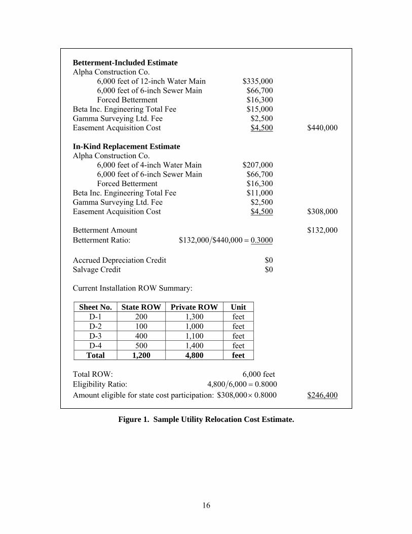
Following the utility adjustment, utilities often submit a final bill with a total amount that differs from the original estimate. If the utility adjustment includes betterments and/or an eligibility ratio applies, the betterment and eligibility ratios determined in the estimate apply to the final bill. The betterment ratio applies before deducting accrued depreciation and salvage values. Figure 1 shows a sample estimate calculation for a utility adjustment that includes both betterments and eligibility. A utility needs to move a 4-inch water main and a 6-inch gravity sewer main on a state highway improvement project. Both facilities are located partly in the

15
state ROW (1,200 feet) and partly on a private easement (4,800 feet) with a total estimated length of 6000 feet. The utility wants to use the opportunity to upgrade the diameter of the water line to 12 inches. To adjust the lines, the utility will need to purchase a new easement on private property. Further, the meters used in the original installation no longer comply with local codes and need replacement with an upgraded version that is more expensive. The estimate does not include mobilization costs under the assumption another project nearby already absorbs those costs. Also, the estimate does not include traffic control under the assumption the highway contractor is responsible for all traffic control activities at the job site. To calculate the amount eligible for state participation, the utility submits an in-kind estimate and a betterment estimate, along with information of the existing utility’s location in public and private ROW. Only the portion of the facility located on the private easement (4,800 feet) is eligible for reimbursement. Figure 2 shows the corresponding final bill. Compared to the estimate, some of the quantities have increased, which requires a recalculation of the amount reimbursable to the utility. To simplify the calculation, the assumption is that changes in cost had no effect on eligibility, and TxDOT made no previous payments to the utility during construction. As a final note, there are different requirements for lump sum agreements and actual cost agreements. Although no federal limit exists for lump sum agreements, TxDOT limits these contracts to $100,000, unless otherwise approved by the ROW Division. A lump sum contract requires a very detailed estimate but no billing itemization and no audit following receipt of the final bill. By comparison, actual cost contracts require detailed estimates and detailed itemized billing. In addition, upon receipt of the final bill, TxDOT retains 10 percent of the final bill pending completion of a TxDOT audit. TxDOT can also reduce reimbursements of utility relocations if the relocation is delayed as a result of circumstances under the control of the utility. Section 203.094 of the Texas Transportation Code specifies that for each 30-day period or portion of a 30-day period, TxDOT may reduce the reimbursement to the utility by 10 percent ( 3).
16
Betterment-Included Estimate Alpha Construction Co.
6,000 feet of 12-inch Water Main $335,000 6,000 feet of 6-inch Sewer Main $66,700 Forced Betterment $16,300 Beta Inc. Engineering Total Fee $15,000 Gamma Surveying Ltd. Fee $2,500 Easement Acquisition Cost $4,500 $440,000
In-Kind Replacement Estimate Alpha Construction Co.
6,000 feet of 4-inch Water Main $207,000 6,000 feet of 6-inch Sewer Main $66,700 Forced Betterment $16,300
Beta Inc. Engineering Total Fee $11,000 Gamma Surveying Ltd. Fee $2,500 Easement Acquisition Cost $4,500 $308,000
Betterment Amount $132,000 Betterment Ratio: 3000.0000,440$000,132$ =
Accrued Depreciation Credit $0 Salvage Credit $0
Current Installation ROW Summary:
Sheet No. State ROW Private ROW Unit
D-1 200 1,300 feet D-2 100 1,000 feet D-3 400 1,100 feet D-4 500 1,400 feet
Total 1,200 4,800 feet
Total ROW: 6,000 feet Eligibility Ratio: 8000.0000,6800,4 = Amount eligible for state cost participation: 8000.0000,308$ × $246,400
Figure 1. Sample Utility Relocation Cost Estimate.

17
7,000 feet of 12-inch Water Main $470,000 7,000 feet of 6-inch Sewer Main $91,700 Forced Betterment $16,300
Beta Inc. Engineering Total Fee $15,000 Gamma Surveying Ltd. Fee $2,500 Easement Acquisition Cost $4,500 $600,000
Betterment Ratio (from estimate) 0.3000 Cost of Betterment 3000.0000,600$ × $180,000
Total Adjustment without Betterment $420,000 Accrued Depreciation Credit $0
Salvage Credit $5,000 $5,000 Total Adjustment with Credits $415,000 Eligibility Ratio (from estimate) 0.8000 Amount Reimbursed to Utility 8000.0000,415$ × $332,000
Figure 2. Sample Utility Relocation Final Bill.
REVIEW OF SAMPLE REIMBURSABLE UTILITY AGREEMENT COST DATA
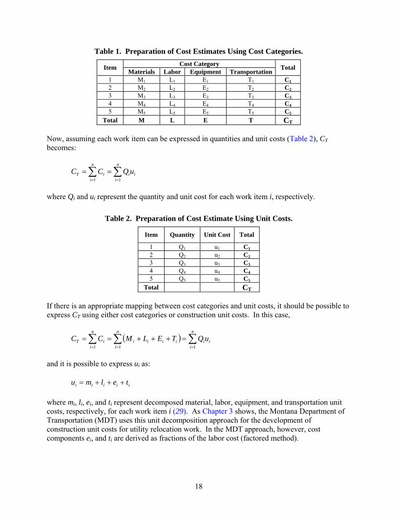
As mentioned previously, utilities prepare cost estimates by breaking down work items into cost categories. Utilities also have the option to use construction unit costs to prepare cost estimates. It should be possible to translate cost categories into construction unit costs provided there is a well established mechanism to map cost categories to work units. To illustrate this point, consider the various categories in Table 1. In general, the total cost CT is: TELMCT +++= where M, L, E, and T are total material, labor, equipment, and transportation category costs, respectively, including overhead and indirect components. Disaggregating the project into n work items results in:
( )∑∑==
+++==n
iiiii
n
iiT TELMCC
11
where Mi, Li, Ei, and Ti are total material, labor, equipment, and transportation category costs, respectively, for each work item.
18
Table 1. Preparation of Cost Estimates Using Cost Categories. Cost Category Item Materials Labor Equipment Transportation Total
1 M1 L1 E1 T1 C1 2 M2 L2 E2 T2 C2 3 M3 L3 E3 T3 C3 4 M4 L4 E4 T4 C4 5 M5 L5 E5 T5 C5
Total M L E T CT Now, assuming each work item can be expressed in quantities and unit costs (Table 2), CT becomes:
∑∑==
==n
iii
n
iiT uQCC
11
where Qi and ui represent the quantity and unit cost for each work item i, respectively.
Table 2. Preparation of Cost Estimate Using Unit Costs.
Item Quantity Unit Cost Total
1 Q1 u1 C1 2 Q2 u2 C2 3 Q3 u3 C3 4 Q4 u4 C4 5 Q5 u5 C5
Total CT If there is an appropriate mapping between cost categories and unit costs, it should be possible to express CT using either cost categories or construction unit costs. In this case,
( ) ∑∑∑===
=+++==n
iii
n
iiiii
n
iiT uQTELMCC
111
and it is possible to express ui as: iiiii telmu +++= where mi, li, ei, and ti represent decomposed material, labor, equipment, and transportation unit costs, respectively, for each work item i ( 29). As Chapter 3 shows, the Montana Department of Transportation (MDT) uses this unit decomposition approach for the development of construction unit costs for utility relocation work. In the MDT approach, however, cost components ei, and ti are derived as fractions of the labor cost (factored method).

19
It is not always possible or practical to map certain cost categories to work items, nor is it always practical to use a unit decomposition approach. Examples include engineering fees and ROW acquisition. In this case, it is common to treat those cost categories separately. In other cases, it may be possible to map cost categories to work items through the application of joint cost allocation methods ( 29). In practice, there is a wide range in ways utilities submit relocation cost data for reimbursement. To understand how utilities actually handle and submit utility relocation cost data to TxDOT, the researchers reviewed and analyzed the cost structure of a sample of utility agreements. Since construction estimates and actual billed costs could be different, the analysis focused on utility agreements where TxDOT had received a final bill from the utility and TxDOT had completely processed all billings and finalized the contract. From an initial list of some 290 finalized utility agreements during fiscal years 2003 and 2004, the researchers selected 110 agreements that focused primarily on water and sanitary sewer installations. Table 3 shows the distribution of agreements by district. The researchers conducted a preliminary analysis of the 110 utility agreements and then focused on a subsample of 25 utility agreements chosen at random to conduct a detailed cost structure analysis. The analysis produced a number of observations, which the following subsections summarize.
Table 3. Sample of Reimbursable Utility Agreements with Final Bills in 2003 and 2004. District Name Number of Agreements District Name Number of Agreements Abilene 1 Fort Worth 4 Amarillo 4 Houston 6 Atlanta 4 Laredo 1 Austin 14 Lufkin 7 Beaumont 6 Paris 9 Brownwood 3 Pharr 3 Bryan 10 San Antonio 1 Childress 3 Tyler 4 Corpus Christi 6 Waco 6 Dallas 15 Wichita Falls 2 El Paso 1
Cost Accounting Detail
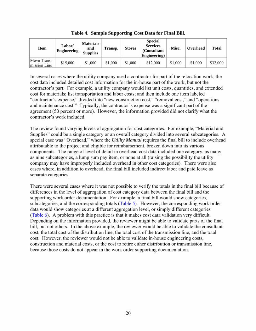
The Utility Manual requires estimates and final bills to include necessary items of work, sufficiently detailed to provide a foundation for the determination of costs (18). A review of utility agreement cost data indicated the requirement was a broad specification that allowed for great variability in accounting detail. For example, while most contracts showed cost categories along with some level of detail about activities within each cost category, some contracts showed only the totals for cost categories without any further detail as to the origin of these costs. As an illustration, Table 4 shows a case where cost data consisted of a table listing several cost categories but only a single work item called “Move Transmission Line.”
20
Table 4. Sample Supporting Cost Data for Final Bill.
Item Labor/ Engineering
Materials and
Supplies Transp. Stores
Special Services
(Consultant Engineering)
Misc. Overhead Total
Move Trans-mission Line $15,000 $1,000 $1,000 $1,000 $12,000 $1,000 $1,000 $32,000
In several cases where the utility company used a contractor for part of the relocation work, the cost data included detailed cost information for the in-house part of the work, but not the contractor’s part. For example, a utility company would list unit costs, quantities, and extended cost for materials; list transportation and labor costs; and then include one item labeled “contractor’s expense,” divided into “new construction cost,” “removal cost,” and “operations and maintenance cost.” Typically, the contractor’s expense was a significant part of the agreement (50 percent or more). However, the information provided did not clarify what the contractor’s work included. The review found varying levels of aggregation for cost categories. For example, “Material and Supplies” could be a single category or an overall category divided into several subcategories. A special case was “Overhead,” where the Utility Manual requires the final bill to include overhead attributable to the project and eligible for reimbursement, broken down into its various components. The range of level of detail in overhead cost data included one category, as many as nine subcategories, a lump sum pay item, or none at all (raising the possibility the utility company may have improperly included overhead in other cost categories). There were also cases where, in addition to overhead, the final bill included indirect labor and paid leave as separate categories. There were several cases where it was not possible to verify the totals in the final bill because of differences in the level of aggregation of cost category data between the final bill and the supporting work order documentation. For example, a final bill would show categories, subcategories, and the corresponding totals (Table 5). However, the corresponding work order data would show categories at a different aggregation level, or simply different categories (Table 6). A problem with this practice is that it makes cost data validation very difficult. Depending on the information provided, the reviewer might be able to validate parts of the final bill, but not others. In the above example, the reviewer would be able to validate the consultant cost, the total cost of the distribution line, the total cost of the transmission line, and the total cost. However, the reviewer would not be able to validate in-house engineering costs, construction and material costs, or the cost to retire either distribution or transmission line, because those costs do not appear in the work order supporting documentation.

21
Table 5. Sample Final Bill. Category Percent Complete Work Done To Date
Consultant Engineering 100% $22,000 Distribution Line Engineering (In-House) 100% $5,000 Construction/Material 100% $10,000 Retire 100% $5,000 Transmission Line Engineering (In-House) 100% $5,000 Construction/Material 100% $15,000 Retire 100% $5,000 Total $67,000
Table 6. Sample Supporting Cost Data (Work Order) for Final Bill. Category Distribution Line Transmission Line
Labor / Engineering $15,000 $20,000 Materials and Supplies $1,000 $1,000 Transportation $1,000 $1,000 Stores $1,000 $1,000 Special Services (Consultant Engineering)
$12,000 $10,000
Miscellaneous $1,000 $1,000 Overhead $1,000 $1,000 Total $32,000 $35,000 Grand Total $67,000
Similar to the level of aggregation for cost categories, the level of aggregation provided with work items also varied considerably. Some agreements listed only a small number of work items such as “Remove Old Facility,” “Install New Facility,” and “Backfill.” The most aggregated agreement included just one work item: “Remove old facility and install new 300′ water line.”
Cost Category and Work Item Consistency of Use
The division of cost data into specific cost categories and work items was inconsistent across agreements. In some cases, cost categories were omitted. In other cases, cost categories were combined with other categories or included in the bill as work items. An example of a combination of cost categories was transportation and equipment. An example of a work item that was sometimes listed as a cost category was operation and maintenance. Some agreements listed operation and maintenance as a work item and included the corresponding cost category data (such as labor, equipment, and transportation). However, other agreements listed operation and maintenance as a cost category associated with a number of work items such as removing old lines or installing new lines. The lack of construction specification information made it difficult to confirm whether some work items or cost categories were actually part of the utility relocation work. For example, some agreements included removal in the final bill, but other agreements did not. As a result, it was not possible to confirm whether removal was part of the utility relocation work. The lack of

22
adequate construction specification information can make cost comparisons among utility relocation projects very difficult. In some cases, the lack of consistency between categories and work items did not occur until the final bill. For example, one cost estimate included the cost for consulting engineering as a cost category assigned to several work items such as removal, design, and construction. However, the final bill treated consulting engineering as a separate work item along with removal, design, and construction. The total cost remained the same because the utility company deducted the cost for consulting engineering from removal, design, and construction.
Use of Unit Costs
Except for material costs, utility agreements rarely included unit cost data. Utility companies typically considered labor, overhead, and transportation costs separately and not in the form of unit costs but in the form of lump sums. In the case of professional services such as engineering and surveying, most agreements included lump sums, making it difficult to verify related expenses. In a few cases, the utility agreement documentation included consultant wage/billable rates, number of hours, and extended total, along with other related costs, such as mileage, meals, computer time, and copying fees. In some cases, overhead costs applied to professional service wages. Unit cost data utility companies provided in the final bill were typically different from those included in the original cost estimate. Final quantities also varied from the original estimates. There was not a trend suggesting unit costs in the final bill were consistently higher or consistently lower than unit costs in the original estimate. That final unit costs were different from those in the original estimate is not surprising considering that original cost estimates are normally preliminary or engineer’s estimates. However, from the available documentation, it was not possible to verify whether TxDOT validated, or otherwise reviewed and approved, the unit costs utility companies and their contractors agreed upon.
Other Issues
Other than the requirement to include certain cost categories in the estimate and for billings to follow a similar structure as the estimate for comparison purposes, TxDOT does not currently require a certain structure for cost data submissions. Current requirements are basic and result in a multitude of billing structures. The analysis found the structure of the cost data that utility companies submit to be essentially unique to individual utility companies. The uniqueness of the cost structure makes it difficult to validate work items and summarized costs. In a simple example, some utility companies included the amount of hours worked in the same column as category costs, making the process to understand and review billings more difficult. The analysis also found cost data that lacked enough supporting documentation to determine reimbursement eligibility. For example, tax cost data often did not clarify whether the taxes were local, state, or federal. Likewise, there were agreements that included miscellaneous overhead cost data, but did not provide enough information to determine whether all overhead

23
costs were reimbursable. There were also cases of mislabeled cost data. For example, an agreement included a cost category labeled “Contributions” with a negative dollar amount, which at first sight suggested a contribution of the utility company to the construction project. However, further analysis confirmed the cost was in reality a credit for a previous payment TxDOT had made to the utility company. Supporting cost documentation also tends to follow rather unique formats, making it very difficult and time consuming for a reviewer to validate cost data that utility companies provide. For example, some utility companies might provide lengthy listings of cost data, of which only a small fraction actually pertain to the project, leaving it up to the reviewer to filter out all unnecessary cost data. In other cases, a utility company might provide long lists of unit cost documentation, listing each bolt and screw along with the corresponding estimated unit cost, estimated quantity, final unit cost, and final quantity. However, the same document only provides the total cost, and not the extended cost per unit. In order to verify the total cost, a reviewer would need to enter all quantity and unit cost data into a spreadsheet, which can be extremely time consuming and probably not a realistic option in many cases. Further, in some cases utility companies simply do not provide the necessary information to validate costs.


25
CHAPTER 3. APPLICABILITY OF THE UNIT COST APPROACH FOR UTILITY RELOCATION WORK
INTRODUCTION
The previous chapter documented a variety of approaches utility companies follow to submit relocation cost data to TxDOT. The analysis highlighted deficiencies of current practices, particularly in relation to long-term usability of the data for utility relocation cost tracking and construction cost comparison analyses. A task of this research is to evaluate the applicability of construction unit cost methods for utility relocation work at TxDOT. The underlying principle of the unit cost approach is quite simple. As Table 1 in Chapter 2 shows, one multiplies the cost of producing, installing, or purchasing one unit of a particular construction item by the number of units required for a particular project to extend a total cost for that item. However, while the concept is simple, its applicability—and the usability of the resulting data—depends heavily on the level of cost aggregation associated with a work item and the completeness and reliability of the information behind the calculation of the corresponding unit cost. Due to the large number of small components in any large scale construction project, it is common to form aggregated unit costs for items that “naturally” group together. For example, instead of developing separate unit costs for water pipe installation and excavation and backfill (which might include different types of backfill such as conventional backfill and flowable backfill), the analyst would develop a single unit cost per unit length of pipe that includes both pipe and the excavation and backfill. Unfortunately, this approach can make it very difficult to uniformly identify elements to include in the aggregated unit cost, which, in turn, introduces uncertainty with respect to the applicability and reliability of the unit cost data. In general, as unit costs become more aggregated, the usability of the data for cost comparisons across projects tends to decrease. Some degree of unit cost aggregation is not just unavoidable but actually desirable to facilitate cost analysis, tracking, and comparison. For example, the unit cost of water pipe installation typically includes the cost of installation of relatively minor items such as connectors and fittings, but not major appurtenances such as valves and hydrants, which are usually considered separate payable items. Regardless of the level of aggregation associated with a particular unit cost, it is critical to explicitly identify all the items that are included in each unit cost to enable the comparison of unit costs across projects. It is important to keep in mind that different approaches to utility relocation cost management involve different risks to all the parties involved, which highlights the need to manage risks properly ( 29, 30). To illustrate this need, consider the simple but extreme example of the differences between the following approaches:
• Accept a lump sum estimate and final bill without auditing. This approach involves paying the estimate the utility company submits and includes both the risk of that estimate significantly exceeding actual costs and TxDOT not being a good steward of tax dollars. In this case, the risk to the utility company could vary depending on how well the company manages its cost structure. In general, there is an additional risk to TxDOT

26
because of the lack of audits. However, if the lump sum amount is relatively small, that additional risk could be managed.
• Fully audit cost estimate and actual cost information. This approach involves verifying
all aspects of the direct work (e.g., inspecting 100 percent of labor, materials, and equipment used) as well as direct costs, indirect costs, overhead, and all other aspects contributing to reimbursable costs. The resulting risk to both TxDOT and the utility company in this case is relatively small, at the expense of TxDOT having to dedicate large amounts of resources to the auditing effort. In reality, resources to conduct comprehensive audits are usually scarce, which results in a risk level that is inversely proportional to the availability of auditing resources.
• Accept unit cost data with field verification of actual quantities. This approach involves
accepting unit cost data submitted with the cost estimate and inspecting quantities during construction. In this case, there are two different risks that require different management strategies. The risk associated with the unit cost data is the risk of actual unit costs varying significantly from estimated unit costs. Most agencies manage this risk by making the unit cost data part of the contract—therefore translating part of the risk to the contractor—and by developing acceptable unit cost ranges based on historical databases. This strategy minimizes the need to conduct unit cost data audits. The risk associated with the quantities includes the risk of actual quantities significantly exceeding estimated quantities. In this case, the risk to TxDOT can be quite large if field inspection is not adequate.
COST ESTIMATION
Hendrickson ( 29) classifies construction cost estimates into three major functional types:
• Design Estimates. Owners prepare design estimates, which can vary as follows depending on where the project is in the project development process: screening estimates (or order of magnitude estimates), preliminary estimates, detailed estimates, and engineer’s estimates. Of particular interest here are engineer’s estimates, which rely on plans and specifications in preparation for letting and construction.
• Bid Estimates. Contractors prepare bid estimates for competitive bidding or negotiation and typically include direct construction costs, field supervision, and a markup to cover general overhead and profits. Direct construction costs normally result from a combination of subcontractor quotes (in this case, the burden of cost estimation is typically on the subcontractor), plan quantities, and construction procedure analysis.
• Control Estimates. Both owners and contractors use control estimates to establish cost control both prior to and during construction. Types of control estimates include budget estimates for financing purposes, budget estimates prior to construction, and budget estimates to complete the project.
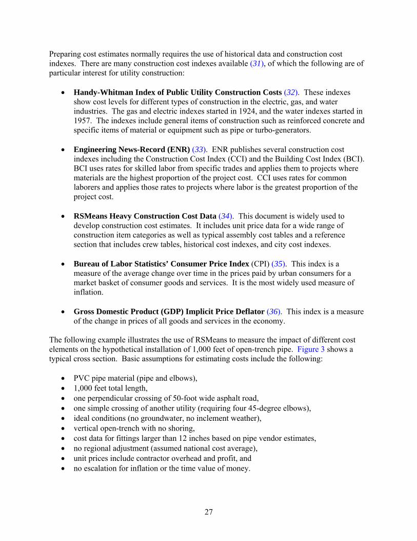
27
Preparing cost estimates normally requires the use of historical data and construction cost indexes. There are many construction cost indexes available ( 31), of which the following are of particular interest for utility construction:
• Handy-Whitman Index of Public Utility Construction Costs ( 32). These indexes show cost levels for different types of construction in the electric, gas, and water industries. The gas and electric indexes started in 1924, and the water indexes started in 1957. The indexes include general items of construction such as reinforced concrete and specific items of material or equipment such as pipe or turbo-generators.
• Engineering News-Record (ENR) ( 33). ENR publishes several construction cost
indexes including the Construction Cost Index (CCI) and the Building Cost Index (BCI). BCI uses rates for skilled labor from specific trades and applies them to projects where materials are the highest proportion of the project cost. CCI uses rates for common laborers and applies those rates to projects where labor is the greatest proportion of the project cost.
• RSMeans Heavy Construction Cost Data ( 34). This document is widely used to
develop construction cost estimates. It includes unit price data for a wide range of construction item categories as well as typical assembly cost tables and a reference section that includes crew tables, historical cost indexes, and city cost indexes.
• Bureau of Labor Statistics’ Consumer Price Index (CPI) ( 35). This index is a
measure of the average change over time in the prices paid by urban consumers for a market basket of consumer goods and services. It is the most widely used measure of inflation.
• Gross Domestic Product (GDP) Implicit Price Deflator ( 36). This index is a measure
of the change in prices of all goods and services in the economy. The following example illustrates the use of RSMeans to measure the impact of different cost elements on the hypothetical installation of 1,000 feet of open-trench pipe. Figure 3 shows a typical cross section. Basic assumptions for estimating costs include the following:
• PVC pipe material (pipe and elbows), • 1,000 feet total length, • one perpendicular crossing of 50-foot wide asphalt road, • one simple crossing of another utility (requiring four 45-degree elbows), • ideal conditions (no groundwater, no inclement weather), • vertical open-trench with no shoring, • cost data for fittings larger than 12 inches based on pipe vendor estimates, • no regional adjustment (assumed national cost average), • unit prices include contractor overhead and profit, and • no escalation for inflation or the time value of money.

28
(a) Without select bedding (b) With select bedding TW
TD4 ft
D
0.5D
TW
TD4 ft
D
0.5D
Select bedding
TEV = TL [TW x TD + 0.5π(D/2)2] TEV = TL [TW x (TD + 0.5D)] SBV = TEV − 0.5π(D/2)2] TW = D + 1.33, D ≤ 2 feet (24 inches)
TW = D + 2, D ≥ 2 feet (24 inches) TD = 4 + 0.5D
TW = Trench width (feet) D = Pipe diameter (feet) TD = Trench depth (feet) TEV = Trench excavation volume (cubic feet) TL = Trench length (feet) SBV = Select bedding volume (cubic feet)
Figure 3. Water Pipe Cross Section. The analysis assumes a number of potential activities and alternative assemblies (Table 7) for a variety of pipe diameters from 4 – 48 inches. For each diameter, the analysis includes a breakdown of costs per activity. For example, Table 7 summarizes the cost breakdown for 4-inch pipe. Table 7 also shows the total costs associated with each assembly and the corresponding aggregated unit cost for the 1,000 feet of pipe. Figure 4 shows the resulting unit costs for all pipe diameters considered.

29
Table 7. Sample Cost Estimate of Pipe Installation Activities and Alternative Assemblies (4-in Diameter Pipe).
Activities
ID Activity Description Quantity Unit 1 Unit Cost ($/Unit)
Total Cost ($)
1 Install pipe 1,000 foot $7.15 $7,150 2 Remove pavement (asphalt, rough edge)
and excavate (deposit along trench) 358 byd3 $4.29 $1,536
3A Backfill with native material and compact
358 yd3 $2.99 $1,070
3B Remove and dispose of native material and backfill with select material
358 yd3 $23.61 $8,453
3C Remove and dispose of native material and backfill with flowable fill
358 yd3 $93.49 $33,472
4 Install select bedding 48 byd3 $21.13 $1,009 5 Increase compaction and repair asphalt
pavement 11 yd2 $61.53 $684
6 Install fittings and crossings: 4 inch 45 degree elbows
4
each
$54
$216
7 Conduct hydrostatic test of pipe 1 each $775 $775
Assemblies by Level of Aggregation
Level Activities Included Total Cost ($)
Length (ft)
Unit Cost ($/ft)
A 1 $7,150 1,000 $7.15 B 1 + 2 $8,686 1,000 $8.69 C 1 + 2 + 3A $9,756 1,000 $9.76
D 2 1 + 2 + 3B $17,369 1,000 $17.37 E 2 1 + 2 + 3C $42,388 1,000 $42.39 F 2 1 + 2 + 3A + 4 $10,766 1,000 $10.77 G 2 1 + 2 + 3A + 4 + 5 $11,449 1,000 $11.45 H 2 1 + 2 + 3A + 4 + 5 + 6 $12,313 1,000 $12.31 I 2 1 + 2 + 3A + 4 + 5 + 6 + 7 $13,088 1,000 $13.09 1 byd3 represents bulk cubic yards. 2 Assumes a 15 percent increase in Activity 2 for loading excavated materials into trucks and disposal.
The work included in a cost item can have a large impact on unit costs, which highlights the importance of consistency and clarity in specifying the work in cost items. In the example Table 7 and Figure 4 illustrate (which use the assumptions in Figure 3), the unit cost of installing a 4-inch water pipe varies from about $7/foot to $42/foot depending on the assumptions made while developing the unit cost. A comparison between assemblies B, C, D, and E reveals the impact of using conventional backfill, select backfill, and flowable backfill on the 4-inch water pipe unit cost is $1.07/foot, $8.68/foot, and $33.70/foot, respectively. The impact of conventional backfill is relatively minor, making it reasonable to include conventional backfill as a subsidiary item to the installation of the pipe. In contrast, the impact of using select backfill or flowable bill can be quite significant, making it advisable to treat select backfill and flowable backfill as distinct payable items. Notice also in Table 7 and Figure 4 the impact of bedding, asphalt repair, fittings, and testing is relatively minor, making it reasonable to include those items as subsidiary items to the installation of the pipe.

30
$0
$50
$100
$150
$200
$250
$300
$350
$400
0 10 20 30 40 50
Pipe Diameter (in)
Uni
t Cos
t ($/
ft)
A B C D E F G H I
ABC
D
E
FGHI
Figure 4. Unit Cost Estimate for Open-Trench Pipe Installation.

31
STATE PRACTICES REGARDING UNIT COSTS
Federal legislation leaves it to the states to develop their own procedures regarding utility relocation costs and reimbursement. As a result, there is a wide range of ways in which states manage utility relocation cost data. A review of a sample of states providing information regarding methods for highway and/or utility construction cost estimating follows.
Florida
The agreement between the Florida Department of Transportation (FDOT) and FHWA does not include the use of unit costs for utility relocation work. Instead, FDOT uses an overall cost approach where FDOT certifies the acceptability of the estimates that utilities provide and accepts FHWA processes to evaluate those estimates. A principal source of information regarding estimates and reimbursements at FDOT is the State Estimates Office’s estimate and pay information website, which includes a basis of estimates handbook, construction cost history, item average unit costs, and estimator software links ( 37). In 1997, the Office of Program Policy Analysis and Governmental Accountability, a state legislative entity charged with review and oversight, reviewed FDOT’s practices with regard to bidding and payment at the FDOT ( 38). The report found successful bids averaged 6 percent below FDOT’s design estimates, but construction costs averaged 9 percent above award amounts, resulting in $32 million in cost overruns. The report also found FDOT paid about $2 million above average bid prices for increased quantities of planned work, and recommended the adoption of a policy to only pay reasonable unit prices when quantity overruns occur. For estimating and monitoring highway construction projects, including utility installations, FDOT uses tools such as the Construction Estimating System (CES), the District Contract Protocol (DCP), the Florida Long Range Estimating System, and several American Association of State Highway and Transportation Officials (AASHTO) Trns*port modules ( 39).
Delaware
The Delaware Department of Transportation (DelDOT’s) Utilities Design Manual describes the process to submit, review, and approve plans, specifications, and estimates based on cost estimates utilities prepare ( 40). The methodology to prepare utility relocation cost estimates requires utilities to break down costs according to a number of cost categories that include preliminary engineering, labor costs, materials, and equipment. The manual includes a sample tabulation of costs, including a final summary.
Montana
The Montana Department of Transportation (MDT) is unique among states in that its agreement with FHWA formalizes the use of a unit cost approach for all phases during the utility relocation process, from estimating to reimbursement ( 41, 42).
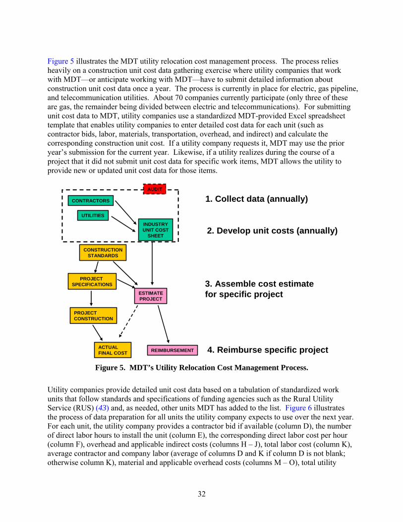
32
Figure 5 illustrates the MDT utility relocation cost management process. The process relies heavily on a construction unit cost data gathering exercise where utility companies that work with MDT—or anticipate working with MDT—have to submit detailed information about construction unit cost data once a year. The process is currently in place for electric, gas pipeline, and telecommunication utilities. About 70 companies currently participate (only three of these are gas, the remainder being divided between electric and telecommunications). For submitting unit cost data to MDT, utility companies use a standardized MDT-provided Excel spreadsheet template that enables utility companies to enter detailed cost data for each unit (such as contractor bids, labor, materials, transportation, overhead, and indirect) and calculate the corresponding construction unit cost. If a utility company requests it, MDT may use the prior year’s submission for the current year. Likewise, if a utility realizes during the course of a project that it did not submit unit cost data for specific work items, MDT allows the utility to provide new or updated unit cost data for those items.
CONTRACTORS
UTILITIES
INDUSTRYUNIT COST
SHEET
CONSTRUCTIONSTANDARDS
PROJECT SPECIFICATIONS
ESTIMATEPROJECT
REIMBURSEMENTACTUALFINAL COST
PROJECTCONSTRUCTION
AUDIT
1. Collect data (annually)
2. Develop unit costs (annually)
3. Assemble cost estimatefor specific project
4. Reimburse specific project
Figure 5. MDT’s Utility Relocation Cost Management Process.
Utility companies provide detailed unit cost data based on a tabulation of standardized work units that follow standards and specifications of funding agencies such as the Rural Utility Service (RUS) ( 43) and, as needed, other units MDT has added to the list. Figure 6 illustrates the process of data preparation for all units the utility company expects to use over the next year. For each unit, the utility company provides a contractor bid if available (column D), the number of direct labor hours to install the unit (column E), the corresponding direct labor cost per hour (column F), overhead and applicable indirect costs (columns H – J), total labor cost (column K), average contractor and company labor (average of columns D and K if column D is not blank; otherwise column K), material and applicable overhead costs (columns M – O), total utility

33
company cost (column P), and total unit cost (column Q). The last column (column Q) contains the unit cost data that, if approved by MDT, utility companies use to prepare cost estimates and eventual reimbursement for all utility relocation projects throughout the year. For example, column Q shows the following total unit costs: Class 5 45-foot pole ($764.58/pole), riser ($1,656.45/riser), and trenching ($2.64/linear foot).
A B C D E F G H I J K
NonRUS Unit No Unit Description
Contractor Bid
Const. Labor Hours
Crew Hourly Rate
Const. Labor
Const.Labor
Overhead
Const. Indirect
Vehicle/ Equip Total
POLE 5 45 220 4.50 69.20 311.40 140.12 55.04 89.03 595.591/0 ACSR 235 3.50 69.20 242.20 108.98 42.81 69.24 463.23
#2 15 KVXLP 515 12.00 69.20 830.40 373.66 146.77 237.41 1588.244/0 USE 11.50 69.20 795.80 358.09 140.65 227.52 1522.07
UC-213 RISER 6.00 69.20 415.20 186.83 73.38 118.71 794.13UG17 PAD 6.00 69.20 415.20 186.83 73.38 118.71 794.13
TRENCHING 0.02 69.20 1.38 0.62 0.24 0.40 2.64
L M N O P QAverage
Contractor/ Company
Material Material Overhead
Total Material
Company Unit Cost
Total Unit Cost
407.80 331.00 25.78 356.78 952.37 764.58349.12 150.00 11.69 161.69 624.92 510.81
1,051.62 1,200.00 93.48 1,293.48 2,881.72 2,345.101,522.07 2,000.00 155.80 2,155.80 3,677.87 3,677.87
794.13 800.00 62.32 862.32 1,656.45 1,656.45794.13 50.00 3.90 53.90 848.03 848.03
2.64 2.64 2.64 Column Definition
A Arbitrary identifier B Unit RUS identifier C Unit description D Outside contractor bid (if available) in $/unit E Company labor hours (estimated from records or contract) F Hourly rate for specified crew in $/(hr x unit) G ExF (labor cost) in $/unit H 0.45*G (overhead rate) in $/unit I 0.18*G (indirect rate) in $/unit J 0.29*G (vehicle rate) in $/unit K G+H+I+J in $/unit L Average of D and K (contractor and company) if D is not blank, else K (company) in $/unit M Material cost in $/unit N 0.08*M (material overhead rate) in $/unit O M+N in $/unit P Sum K+M (utility company unit cost) in $/unit Q L+O (total unit cost) in $/unit
Note: All values shown are fictional and are only intended to demonstrate the use of the methodology.
Figure 6. Sample Unit Cost Calculation Using MDT Approach.
The methodology relies on the application of a series of factors (in this example, 0.45 for overhead labor, 0.18 for indirect construction, 0.29 for vehicle and equipment charges, and 0.08 for material cost overhead). Each utility company derives and justifies these factors on the basis of actual annual ledger data and separately submits this information, which typically varies from utility to utility. For example, for the hypothetical utility company in Figure 6, the total annual direct construction labor cost was $1,000,000, of which payroll overhead costs such as vacation,

34
sick and holiday leave, employer paid payroll taxes, and fringe benefits totaled $450,000. The corresponding labor overhead factor was 0.45. Thus, to compute the labor overhead for any unit in the table above, the labor charge associated with the unit is multiplied by this factor. It may be worth noting that TxDOT uses a somewhat similar approach for the payment of extra work in highway contracts when using the force account method, except it does not tie the calculation of the various factors to ledger data. For example, Item 9, “Measurement and Payment” in the TxDOT standard specification book includes a factor of 0.25 to account for labor overhead, superintendence, profit, and small tools; a 0.25 factor to account for material cost overhead and profit; and a factor of 0.15 to account for equipment overhead and profit ( 44). MDT does not reimburse utilities for engineering services on the basis that utilities have a great deal of control over such costs and in order to avoid having to deal with engineering services approval and documentation. Not reimbursing utilities for engineering services has also resulted in savings to MDT of about $500,000 per year. Likewise, outside contractor bids (column D in Figure 6) do not include material costs, i.e., the bids only include labor rates, overhead, and equipment/vehicle costs. MDT has implemented a procedure that converts unit cost data from Excel into comma-delimited format and then imports the data into an Oracle database, where the data reside in anticipation of any utility relocation project that might take place during the year (Figure 7, Figure 8). In general, MDT validates unit cost data that utilities submit against average unit cost data but does not check the accuracy of every single piece of detailed unit cost data utilities submit, relying instead on sporadic detailed audits of a reduced sample of data submissions. Auditing is usually the responsibility of a staff member at MDT. While the MDT unit cost database contains a large number of entries, exceptional circumstances and areas for which inadequate information exists require negotiations between MDT and affected utilities and/or the determination of default rates.
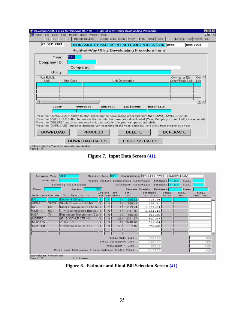
35
Figure 7. Input Data Screen ( 41).
Figure 8. Estimate and Final Bill Selection Screen ( 41).

36
For utility relocation projects during the course of a year, utility companies provide plan-in-hand estimates, which MDT validates using plan quantities and the unit cost database. At the conclusion of the project, the system enables MDT to upload actual quantities and create the final bill based on which MDT reimburses the utility companies. Currently, MDT reimburses 100 percent of eligible costs if the utility company has a compensable property interest and 75 percent if the utility company does not have a compensable interest. This reimbursement policy has promoted excellent cooperation between the utility companies and MDT. According to MDT, their utility relocation unit cost system has resulted in elimination of audits of each utility relocation actual costs, simplified cost estimate preparation and subsequent review and billing, elimination of the need to pre-approve utility consultants or contractors, and elimination of cost overruns for reasons other than increased quantities ( 41). Another advantage is the automation of the unit cost data capture process that eliminates the need for MDT officials to manually enter unit cost data or supporting data into the Oracle database. At the same time, there are some limitations of the Montana approach that might prevent its full implementation in a large state such as Texas. For the submission of unit cost data to MDT prior to any actual utility relocation work, utilities need to make certain assumptions concerning the type, characteristics, and scale of a “typical” project. Making these assumptions for long, linear, rural projects, which are typical in Montana, is relatively straightforward. Still, there is a risk that actual relocation projects might differ in scope with respect to what the utility company assumed during the submission of the detailed unit cost data to the point that the unit cost data originally submitted might not properly represent the actual project. This risk is obviously higher in urban areas and other “abnormal” situations. In an effort to reduce uncertainty and the possibility to negatively impact utilities, MDT decided to create units for several “typical” projects. For example, for each gas pipe material (steel, plastic), MDT has 33 different units for gas pipe installation to represent all possible combinations between three different length ranges (0–500 feet, 500–1,000 feet, and over 1,000 feet) and 11 pipe diameters (0–2, 3, 4, 6, 8, 10, 12, 14, 16, 20, and 24 inches). It would be necessary to calculate a separate unit cost for each of the 33 different units.
Virginia
Two systems the Virginia Department of Transportation (VDOT) developed are the Right of Way and Utility Management System (RUMS) and the Project Cost Estimating System (PCES) ( 45). RUMS enables VDOT to track the ROW acquisition and utility relocation processes. The software enables users to follow transactions, as well as store and customize forms, correspondence, and other project-related documentation. PCES enables the production of scoping or screening cost estimates early during the project development process ( 46). Its development stemmed from the realization that final project costs frequently exceeded initial estimates and a corresponding recommendation by a 2001 legislative study for VDOT to examine ways to improve cost estimates. PCES includes a cost estimation tool, a scoping process, and a website for project development. Project scoping includes a repository of project data, from initial conception to final documentation. PCES takes into consideration a variety of requirements such as land acquisition, utility relocation, preliminary engineering, site preparation, construction, environmental mitigation,
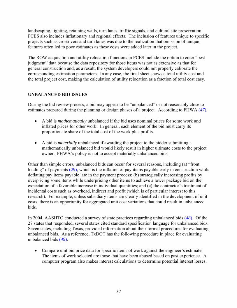
37
landscaping, lighting, retaining walls, turn lanes, traffic signals, and cultural site preservation. PCES also includes inflationary and regional effects. The inclusion of features unique to specific projects such as crossovers and turn lanes was due to the realization that omission of unique features often led to poor estimates as these costs were added later in the project. The ROW acquisition and utility relocation functions in PCES include the option to enter “best judgment” data because the data repository for those items was not as extensive as that for general construction and, as a result, the system developers could not properly calibrate the corresponding estimation parameters. In any case, the final sheet shows a total utility cost and the total project cost, making the calculation of utility relocation as a fraction of total cost easy.
UNBALANCED BID ISSUES
During the bid review process, a bid may appear to be “unbalanced” or not reasonably close to estimates prepared during the planning or design phases of a project. According to FHWA ( 47),
• A bid is mathematically unbalanced if the bid uses nominal prices for some work and inflated prices for other work. In general, each element of the bid must carry its proportionate share of the total cost of the work plus profits.
• A bid is materially unbalanced if awarding the project to the bidder submitting a
mathematically unbalanced bid would likely result in higher ultimate costs to the project owner. FHWA’s policy is not to accept materially unbalanced bids.
Other than simple errors, unbalanced bids can occur for several reasons, including (a) “front loading” of payments ( 29), which is the inflation of pay items payable early in construction while deflating pay items payable late in the payment process; (b) strategically increasing profits by overpricing some items while underpricing other items to achieve a lower package bid on the expectation of a favorable increase in individual quantities; and (c) the contractor’s treatment of incidental costs such as overhead, indirect and profit (which is of particular interest to this research). For example, unless subsidiary items are clearly identified in the development of unit costs, there is an opportunity for aggregated unit cost variations that could result in unbalanced bids. In 2004, AASHTO conducted a survey of state practices regarding unbalanced bids ( 48). Of the 27 states that responded, several states cited standard specification language for unbalanced bids. Seven states, including Texas, provided information about their formal procedures for evaluating unbalanced bids. As a reference, TxDOT has the following procedure in place for evaluating unbalanced bids ( 49):
• Compare unit bid price data for specific items of work against the engineer’s estimate. The items of work selected are those that have been abused based on past experience. A computer program also makes interest calculations to determine potential interest losses.

38
• For the projects selected in the first step, select items that are outside a specific range with respect to the estimate. The range is 100 percent above or 50 percent below the estimate for major items (i.e., those items worth at least 5 percent of the contract or $100,000, whichever is less) and 200 percent above or 75 percent below the estimate for minor items.
• For each item identified in the previous step, verify the estimated quantity. If there is an error in the quantity, TxDOT corrects the quantity estimate and recalculates the entire bid to determine if the low bidder outcome would change. TxDOT awards the contract if the low bidder is not affected. Otherwise, TxDOT rejects all bids and re-lets the project.
• If quantities are accurate, TxDOT determines whether a bid is mathematically or materially unbalanced. For this purpose, TxDOT calculates monthly payouts during the life of the contract based on an assumed schedule and compares the payouts to the estimated payouts of the second bidder. If the payouts to the low bidder could result in loss of interest to the state in an amount greater than the difference between low and second bids, TxDOT considers the low bid to be potentially materially unbalanced. If the contractor can show a reasonable expectation that loss of interest is less than the difference between low and second bids, TxDOT declares the low bid to be mathematically unbalanced and awards the contract. Otherwise, TxDOT declares the bid to be materially unbalanced, rejects all bids, and re-lets the project.
UNIT COST STRUCTURE FOR UTILITY RELOCATION WORK AT TxDOT
At least three examples of current practice support the idea of a systematic unit cost approach for utility relocations at TxDOT: (1) the fact that unit costs and quantities as a basis for estimating total costs are standard in the construction industry; (2) the long collective experience at many state DOTs, including TxDOT, using unit costs for highway construction; and (3) as mentioned previously, Montana’s 10 years of experience with a unit cost approach for utility relocation work. The question is what utility relocation unit cost structure and implementation framework would be advisable for TxDOT. After all, as mentioned previously, there may be many different ways to implement a unit cost approach. In developing a proposed unit cost structure and implementation framework, it is important to realize that only a small fraction of reimbursable utility agreements at TxDOT currently use construction unit costs. As Chapter 2 documented, the vast majority of utility agreements follow the traditional cost category-based approach. It is possible that a substantial number of utilities do not currently use construction unit costs as part of their business operations. However, it is perhaps more reasonable to assume that utilities follow the traditional cost category-based approach in their utility relocation cost submissions to TxDOT because the Utility Manual ( 2) encourages those utilities to follow the traditional approach. The Utility Manual does indicate that utilities may use construction unit costs, but the overall message in the manual is that utilities need to structure the information they provide to TxDOT in a format that, in the end, is inconsistent with the use of unit cost approaches.

39
It is also important to realize that detailed disaggregate unit cost-based systems such as that used in Montana may be too costly and impractical to implement and maintain in a large state such as Texas, at least in the short term. Conversations with TxDOT officials further suggest there would be considerable resistance to the implementation of a system that requires storing and managing such a large amount of detailed information for the production of unit cost data but for which the long-term usability of the detailed data does not seem clear. It is also possible that to make this type of system effective in Texas, it would be necessary to subscribe to a new general utility reimbursement agreement with FHWA. To have a reasonable chance of success at TxDOT, a systematic utility relocation unit cost approach would need to satisfy, at a minimum, the following functional requirements:
• Consistency with TxDOT’s highway construction unit cost structure. One of the reasons this requirement is important is that a small but significant percentage of utility relocation work at TxDOT is included in highway contracts. In general, TxDOT uses unit costs that are not too disaggregated, which facilitates contract management because it helps to maintain the number of pay items at a reasonable level. At the same time, TxDOT has procedures in place that facilitate unit cost data analyses and comparisons that rely on a database of historical unit cost data (including unit cost data from the low bid, the winning bid, and all other bids for every highway contract). Effectively, this approach reduces uncertainty in the unit cost data because it enables the use of statistical methods to determine central tendency estimators—as well as dispersion estimators to detect outliers. It also eliminates the need to require supporting documentation for unit cost data contractors submit.
• Consistency with a set of standard specifications and provisions, including TxDOT’s
standard specifications for construction and maintenance of highway facilities ( 44). The following chapters describe a proposed framework of standard specifications for utility relocation work at TxDOT that provides a consistent set of pay items, subsidiary items, and measurement units.
• Support for current federal and state laws and regulations concerning utility
reimbursement requirements. Typical highway contracts follow a traditional quote/bid approach where contractors provide a tabulation of quantities, unit costs, and total costs but not much else in the form of additional supporting cost documentation. In contrast, utility reimbursement laws and regulations require the collection of a wealth of information from utilities to determine elements such as reimbursement eligibility, betterment ratios, and accrued depreciation. However, a closer examination of these elements reveals that most of these cost elements are actually accounting cost elements. This observation leads to the realization that a unit cost approach for utility relocation work that completely separates accounting cost data from other cost elements should be feasible, while at the same time supporting TxDOT’s highway construction unit cost structure.
• Support the development of utility relocation cost estimates at various stages in the utility
relocation process.

40
• Provide adequate documentation and training for TxDOT personnel to effectively utilize
the system adopted. The researchers developed a prototype unit cost structure that supports the functional requirements described above. The first requirement above (consistency with TxDOT construction contract bids) and differences between bids and what is reimbursable to utility companies preclude the direct estimate of reimbursable-only work. The proposed approach addresses the dual requirements of compatibility with TxDOT construction bidding and reimbursement requirements by first estimating costs that are compatible with TxDOT construction bids and then adjusting for non-reimbursable costs. In general terms, the prototype structure assumes there is a reference set of unit costs associated with a corresponding set of bid items following the specification framework described in Chapter 4 that, in combination with a set of quantities, provides a reference dollar amount from which it would be necessary to deduct any non-reimbursable amounts. The reference dollar amount therefore represents a neutral case, i.e., the cost to build the utility facility regardless of who owns it (TxDOT or the utility company). Like in a typical highway project, there may be several types of utility relocation cost estimates: design estimates, bid estimates, and control estimates. The basic assumption is that engineer’s estimates provide the basis for utility agreements between TxDOT and utility companies. As mentioned previously, cost data for engineer’s estimates could include data from prior bids and/or data from commercial databases such as RSMeans ( 32). Bid estimates would result from bids from potential contractors and, as such, they should be the same regardless of who pays the contractor initially (TxDOT or the utility company). However, because bid estimates could differ from engineer’s estimates, it would be necessary to check for materially unbalanced bids, as the previous section described. Final unit costs—as well as total contract amounts—agreed upon between the utility company and its contractor would also be subject to TxDOT’s review and approval. While unit costs from engineer’s estimates and bid estimates could vary, in general it is reasonable to expect unit costs included in control estimates to be the same as those agreed upon with the contractor. Readers should be aware that a contractor’s unit price becomes a unit cost for TxDOT (or a utility company) if the bid is accepted. In general, this report uses the term “unit cost” for simplicity. However, it is clear that depending on the context (e.g., when discussing bids from contractors), a “unit cost” could actually be a “unit price.” This report documents the structure (specification requirements, units of measurement, as well as a listing of bid items and subsidiary items) necessary for potential contractors to develop those unit prices. To account for non-reimbursable costs (i.e., the difference between the reference dollar amount and costs that are eligible for reimbursement [ 2]), the prototype structure assumes two alternative approaches utility companies could use:
• In the first approach, utility companies would develop a set of “non-reimbursable unit costs” that would only include non-reimbursable cost components. Multiplying these “non-reimbursable unit costs” by the utility relocation quantities would produce a total non-reimbursable amount. The advantage of this approach is that utility companies and

41
TxDOT would be able to determine the impact of non-reimbursable cost components on each individual construction unit cost. The disadvantage is that “non-reimbursable unit costs” may not be intuitively clear and utility companies might have difficulty calculating those costs.
• In the second approach, utility companies would document the non-reimbursable component associated with cost categories such as labor, overhead, material, and transportation, using roughly the same procedure utility companies have used in the past to document utility relocation costs. The total “non-reimbursable” amount would be the same as in the first approach.
Because not all cost components would necessarily map easily to a unit cost structure (e.g., ROW acquisition, engineering services, or surveying), the prototype structure assumes these costs are added separately to the calculation. To illustrate the use of the prototype structure, the researchers created a template that includes both non-reimbursable cost approaches. Using the cost estimate in Figure 1, Figure 9 shows two engineer’s estimates assuming a utility company provides “non-reimbursable unit costs.” One estimate assumes replacement of the facility including betterment and the other one assumes in-kind replacement. The estimates include a sample calculation of betterment ratio, project credits, reimbursement eligibility, and state cost participation. Figure 10 shows the (winning) bid estimate, assuming the same quantities but slightly different unit costs as those shown in Figure 9. Figure 11 shows the corresponding final bill. In this example, the engineer’s estimate of the total net utility relocation cost was $440,000, the bid estimate was $500,000, and the amount of the final bill was $600,000. Using the 0.30 betterment ratio determined by the two estimates in Figure 9, the elective betterment amount of the final bill was $180,000 and the total adjustment cost without elective betterment in the final bill was $420,000. After applying a credit of $5,000 for salvageable materials and the 0.80 eligibility ratio from Figure 9, the eligibility for state cost participation, which is the actual amount reimbursed to the utility, was $332,000.

42
Group Item No.
Bid Code Description Unit
ForcedBetter-ment
Quantity U1
($/unit)Cost1
($)U2
($/unit)Cost2
($)U1 - U2
($/unit)
Improv. due to Hwy
Const.
Net Cost($)
A) Betterment-Included EstimateConstruction XXXX XXXX Structural Excavation (Pipes) Cu yard No 2,000 $5 $10,000 $1 $2,000 $4 - $8,000
XXXX XXXX Cutting and Restoring Pavement Sq yard No 200 $20 $4,000 $2 $400 $18 - $3,600XXXX XXXX Cement Stabilized Backfill Cu yard No 200 $30 $6,000 $2 $400 $28 - $5,600XXXX XXXX Trench Excavation Protection Foot No 6,000 $2 $12,000 $1 $6,000 $1 - $6,000XXXX XXXX Water Pipe (Ductile Iron)(12") Foot No 6,000 $50 $300,000 $2 $12,000 $48 - $288,000XXXX XXXX Water Pipe (Copper)(1") Foot No 500 $5 $2,500 $1 $500 $4 - $2,000XXXX XXXX Water Pipe (Ductile Iron)(HDD)(12") Foot No 200 $30 $6,000 $3 $600 $27 - $5,400XXXX XXXX Gravity Sanitary Sewer Pipe (PVC)(HAB)(6") Foot No 100 $7 $700 $2 $200 $5 - $500XXXX XXXX Water Valve (Gate)(12") Each No 4 $1,500 $6,000 $100 $400 $1,400 - $5,600XXXX XXXX Hydrant (Type 1) Each Yes 10 $1,500 $15,000 $100 $1,000 $1,400 $7,000 $14,000XXXX XXXX Gravity Sanitary Sewer Pipe (PVC)(6") Foot No 6,000 $10 $60,000 $1 $6,000 $9 - $54,000XXXX XXXX Manhole (Type 1)(10') Each No 10 $2,500 $25,000 $200 $2,000 $2,300 - $23,000XXXX XXXX Water Meter (1") Each Yes 10 $150 $1,500 $10 $100 $140 - $1,400XXXX XXXX Water Meter Box Each Yes 10 $100 $1,000 $10 $100 $90 - $900
Right of Way Easement Acquisition Sq foot 500 $20 $4,500 $0 $20 $4,500
Prof. Services Engineering Services Fee $17,000 $2,000 $15,000Surveying Fee $3,500 $1,000 $2,500
Total $474,700 $34,700 $7,000 $440,000B) In-Kind Replacement EstimateConstruction XXXX XXXX Structural Excavation (Pipes) Cu yard No 1,000 $5 $5,000 $1 $1,000 $4 - $4,000
XXXX XXXX Cutting and Restoring Pavement Sq yard No 200 $20 $4,000 $2 $400 $18 - $3,600XXXX XXXX Select Bedding Cu yard No 200 $30 $6,000 $2 $400 $28 - $5,600XXXX XXXX Trench Excavation Protection Foot No 6,000 $2 $12,000 $1 $6,000 $1 - $6,000XXXX XXXX Water Pipe (Ductile Iron)(4") Foot No 6,000 $30 $180,000 $2 $12,000 $28 - $168,000XXXX XXXX Water Pipe (Copper)(1") Foot No 500 $5 $2,500 $1 $500 $4 - $2,000XXXX XXXX Water Pipe (Ductile Iron)(HDD)(4") Foot No 200 $30 $6,000 $3 $600 $27 - $5,400XXXX XXXX Gravity Sanitary Sewer Pipe (PVC)(HAB)(6") Foot No 100 $7 $700 $2 $200 $5 - $500XXXX XXXX Water Valve (Gate)(4") Each No 4 $500 $2,000 $100 $400 $400 - $1,600XXXX XXXX Hydrant (Type 1) Each Yes 10 $1,500 $15,000 $100 $1,000 $1,400 $7,000 $14,000XXXX XXXX Gravity Sanitary Sewer Pipe (PVC)(6") Foot No 6,000 $10 $60,000 $1 $6,000 $9 - $54,000XXXX XXXX Manhole (Type 1)(10') Each No 10 $2,500 $25,000 $200 $2,000 $2,300 - $23,000XXXX XXXX Water Meter (1") Each Yes 10 $150 $1,500 $10 $100 $140 - $1,400XXXX XXXX Water Meter Box Each Yes 10 $100 $1,000 $10 $100 $90 - $900
Right of Way Easement Acquisition Sq foot 500 $20 $4,500 $0 $20 $4,500
Prof. Services Engineering Services Fee $12,500 $1,500 $11,000Surveying Fee $3,500 $1,000 $2,500
Total $341,200 $33,200 $7,000 $308,000C) BettermentBetterment-Included Estimate $440,000In-Kind Replacement Estimate - $308,000Betterment amount = $132,000Betterment ratio 0.3000D) CreditsDepreciation $0Salvag. Mat. + $0Total Credits = $0In-Kind Replacement Estimate $308,000Improvements due to Highway Construction - $7,000Max. Allowed Credits = $301,000Total Credits Payable (Lesser of Total Credits and Max. Allowed Credits) $0E) EligibilityState ROW Length Foot 1,200Private ROW Length Foot 4,800Total ROW Length Foot 6,000Private ROW Length Foot 4,800Total ROW Length Foot / 6,000Eligibility Ratio = 0.8000F) State Cost Participation EstimateIn-Kind Replacement Estimate $308,000Total Credits payable - $0Net In-Kind Replacement Estimate = $308,000Eligibility Ratio • 0.8000State Cost Participation Estimate = $246,400
Figure 9. Sample Engineer’s Estimate (with Unit Cost-Based Non-Reimbursable Costs).

43
Group Item No.
Bid Code Description Unit
ForcedBetter-ment
Quantity U1
($/unit)Cost1
($)U2
($/unit)Cost2
($)U1 - U2
($/unit)
Improv. due to Hwy
Const.
Net Cost($)
A) Betterment-Included EstimateConstruction XXXX XXXX Structural Excavation (Pipes) Cu yard No 2,000 $5 $10,000 $1 $2,000 $4 - $8,000
XXXX XXXX Cutting and Restoring Pavement Sq yard No 200 $20 $4,000 $2 $400 $18 - $3,600XXXX XXXX Cement Stabilized Backfill Cu yard No 200 $32 $6,400 $2 $400 $30 - $6,000XXXX XXXX Trench Excavation Protection Foot No 6,000 $2 $12,000 $1 $6,000 $1 - $6,000XXXX XXXX Water Pipe (Ductile Iron)(12") Foot No 6,000 $55 $330,000 $2 $12,000 $53 - $318,000XXXX XXXX Water Pipe (Copper)(1") Foot No 500 $5 $2,500 $1 $500 $4 - $2,000XXXX XXXX Water Pipe (Ductile Iron)(HDD)(12") Foot No 200 $28 $5,600 $3 $600 $25 - $5,000XXXX XXXX Gravity Sanitary Sewer Pipe (PVC)(HAB)(6") Foot No 100 $7 $700 $2 $200 $5 - $500XXXX XXXX Water Valve (Gate)(12") Each No 4 $1,500 $6,000 $100 $400 $1,400 - $5,600XXXX XXXX Hydrant (Type 1) Each Yes 10 $1,500 $15,000 $100 $1,000 $1,400 $7,000 $14,000XXXX XXXX Gravity Sanitary Sewer Pipe (PVC)(6") Foot No 6,000 $15 $90,000 $1 $6,000 $14 - $84,000XXXX XXXX Manhole (Type 1)(10') Each No 10 $2,500 $25,000 $200 $2,000 $2,300 - $23,000XXXX XXXX Water Meter (1") Each Yes 10 $150 $1,500 $10 $100 $140 - $1,400XXXX XXXX Water Meter Box Each Yes 10 $100 $1,000 $10 $100 $90 - $900
Right of Way Easement Acquisition Sq foot 500 $20 $4,500 $0 $20 $4,500
Prof. Services Engineering Services Fee $17,000 $2,000 $15,000Surveying Fee $3,500 $1,000 $2,500
Total $534,700 $34,700 $7,000 $500,000B) BettermentBetterment Ratio (from Engineer's Estimate) 0.3000Construction Estimate • $500,000Betterment Amount = $150,000Total Adjustment Cost without Betterment = $350,000C) CreditsDepreciation $0Salvag. Mat. XXXX XXXX Water Valves, Hydrants, Manholes Lump Sum + $5,000Total Credits = $5,000Total Adjustment Cost without Betterment $350,000Improvements due to Highway Construction - $7,000Max. Credits allowed = $343,000Total Credits Payable (Lesser of Total Credits and Max. Allowed Credits) $5,000D) EligibilityState ROW Length Foot 1,200Private ROW Length Foot 4,800Total ROW Length Foot 6,000Private ROW Length Foot 4,800Total ROW Length Foot / 6,000Eligibility Ratio = 0.8000E) State Cost Participation EstimateIn-Kind Replacement Estimate $350,000Total Credits Payable - $5,000Net In-Kind Replacement Estimate = $345,000Eligibility Ratio • 0.8000State Cost Participation Estimate = $276,000
Figure 10. Sample Bid Estimate (with Unit Cost-Based Non-Reimbursable Costs).

44
Group Item No.
Bid Code Description Unit
ForcedBetter-ment
Quantity U1
($/unit)Cost1
($)U2
($/unit)Cost2
($)U1 - U2
($/unit)
Improv. due to Hwy
Const.
Net Cost($)
A) Betterment-Included Final BillConstruction XXXX XXXX Structural Excavation (Pipes) Cu yard No 5,625 $5 $28,125 $1 $5,625 $4 - $22,500
XXXX XXXX Cutting and Restoring Pavement Sq yard No 200 $20 $4,000 $2 $400 $18 - $3,600XXXX XXXX Cement Stabilized Backfill Cu yard No 200 $32 $6,400 $2 $400 $30 - $6,000XXXX XXXX Trench Excavation Protection Foot No 7,000 $2 $14,000 $1 $7,000 $1 - $7,000XXXX XXXX Water Pipe (Ductile Iron)(12") Foot No 7,000 $55 $385,000 $2 $14,000 $53 - $371,000XXXX XXXX Water Pipe (Copper)(1") Foot No 500 $5 $2,500 $1 $500 $4 - $2,000XXXX XXXX Water Pipe (Ductile Iron)(HDD)(12") Foot No 900 $28 $25,200 $3 $2,700 $25 - $22,500XXXX XXXX Gravity Sanitary Sewer Pipe (PVC)(HAB)(6") Foot No 100 $7 $700 $2 $200 $5 - $500XXXX XXXX Water Valve (Gate)(12") Each No 4 $1,500 $6,000 $100 $400 $1,400 - $5,600XXXX XXXX Hydrant (Type 1) Each Yes 10 $1,500 $15,000 $100 $1,000 $1,400 $7,000 $14,000XXXX XXXX Gravity Sanitary Sewer Pipe (PVC)(6") Foot No 7,000 $15 $105,000 $1 $7,000 $14 - $98,000XXXX XXXX Manhole (Type 1)(10') Each No 10 $2,500 $25,000 $200 $2,000 $2,300 - $23,000XXXX XXXX Water Meter (1") Each Yes 10 $150 $1,500 $10 $100 $140 - $1,400XXXX XXXX Water Meter Box Each Yes 10 $100 $1,000 $10 $100 $90 - $900
Right of Way Easement Acquisition Sq foot 500 $20 $4,500 $0 $20 $4,500
Prof. Services Engineering Services Fee $17,000 $2,000 $15,000Surveying Fee $3,500 $1,000 $2,500
Total $644,425 $44,425 $7,000 $600,000B) BettermentBetterment Ratio (from Estimate) 0.3000Final Bill Amount • $600,000Betterment Amount = $180,000Total Adjustment Cost without Betterment = $420,000C) CreditsDepreciation $0Salvag. Mat. XXXX XXXX Water Valves, Hydrants, Manholes Lump Sum + $5,000Total Credits = $5,000Total Adjustment Cost without Betterment $420,000Improvements due to Highway Construction - $7,000Max. Credits Allowed = $413,000Total Credits Payable (Lesser of Total Credits and Max. Allowed Credits) $5,000D) State Cost ParticipationTotal Adjustment Cost without Betterment $420,000Credits - $5,000Net In-Kind Replacement Estimate = $415,000Eligibility Ratio (from Estimate) • 0.8000State Cost Participation = $332,000
Figure 11. Sample Final Bill (with Unit Cost-Based Non-Reimbursable Costs). By comparison, Figure 12 shows two detailed engineer’s estimates (betterment and in-kind) assuming a utility company provides non-reimbursable cost information associated with labor, overhead, and transportation categories. For simplicity, Figure 12 only shows total non-reimbursable costs by cost category (labor, overhead, transportation), but, as required, the information provided could be more disaggregated. Figure 13 shows the bid estimate, and Figure 14 shows the corresponding final bill. As mentioned previously, some utilities might find it counterintuitive to use a unit costs approach to determine non-reimbursable costs. Those utilities might prefer to use alternative cost calculation methods that are consistent with the utility’s accounting practices and, at the same time, are acceptable to TxDOT. Figure 12 illustrates one potential approach, where the utility calculated non-reimbursable labor, overhead, and transportation costs for the entire project following existing Utility Manual guidelines ( 2).
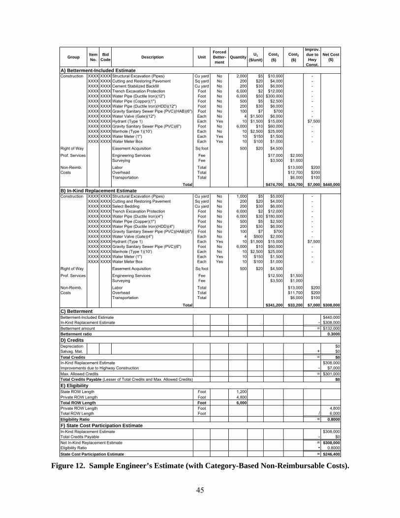
45
Group Item No.
Bid Code Description Unit
ForcedBetter-ment
QuantityU1
($/unit)Cost1
($)Cost2
($)
Improv. due to Hwy
Const.
Net Cost($)
A) Betterment-Included EstimateConstruction XXXX XXXX Structural Excavation (Pipes) Cu yard No 2,000 $5 $10,000 -
XXXX XXXX Cutting and Restoring Pavement Sq yard No 200 $20 $4,000 -XXXX XXXX Cement Stabilized Backfill Cu yard No 200 $30 $6,000 -XXXX XXXX Trench Excavation Protection Foot No 6,000 $2 $12,000 -XXXX XXXX Water Pipe (Ductile Iron)(12") Foot No 6,000 $50 $300,000 -XXXX XXXX Water Pipe (Copper)(1") Foot No 500 $5 $2,500 -XXXX XXXX Water Pipe (Ductile Iron)(HDD)(12") Foot No 200 $30 $6,000 -XXXX XXXX Gravity Sanitary Sewer Pipe (PVC)(HAB)(6") Foot No 100 $7 $700 -XXXX XXXX Water Valve (Gate)(12") Each No 4 $1,500 $6,000 -XXXX XXXX Hydrant (Type 1) Each Yes 10 $1,500 $15,000 $7,500XXXX XXXX Gravity Sanitary Sewer Pipe (PVC)(6") Foot No 6,000 $10 $60,000 -XXXX XXXX Manhole (Type 1)(10') Each No 10 $2,500 $25,000 -XXXX XXXX Water Meter (1") Each Yes 10 $150 $1,500 -XXXX XXXX Water Meter Box Each Yes 10 $100 $1,000 -
Right of Way Easement Acquisition Sq foot 500 $20 $4,500
Prof. Services Engineering Services Fee $17,000 $2,000Surveying Fee $3,500 $1,000
Non-Reimb. Labor Total $13,000 $200Costs Overhead Total $12,700 $200
Transportation Total $6,000 $100
Total $474,700 $34,700 $7,000 $440,000B) In-Kind Replacement EstimateConstruction XXXX XXXX Structural Excavation (Pipes) Cu yard No 1,000 $5 $5,000 -
XXXX XXXX Cutting and Restoring Pavement Sq yard No 200 $20 $4,000 -XXXX XXXX Select Bedding Cu yard No 200 $30 $6,000 -XXXX XXXX Trench Excavation Protection Foot No 6,000 $2 $12,000 -XXXX XXXX Water Pipe (Ductile Iron)(4") Foot No 6,000 $30 $180,000 -XXXX XXXX Water Pipe (Copper)(1") Foot No 500 $5 $2,500 -XXXX XXXX Water Pipe (Ductile Iron)(HDD)(4") Foot No 200 $30 $6,000 -XXXX XXXX Gravity Sanitary Sewer Pipe (PVC)(HAB)(6") Foot No 100 $7 $700 -XXXX XXXX Water Valve (Gate)(4") Each No 4 $500 $2,000 -XXXX XXXX Hydrant (Type 1) Each Yes 10 $1,500 $15,000 $7,500XXXX XXXX Gravity Sanitary Sewer Pipe (PVC)(6") Foot No 6,000 $10 $60,000 -XXXX XXXX Manhole (Type 1)(10') Each No 10 $2,500 $25,000 -XXXX XXXX Water Meter (1") Each Yes 10 $150 $1,500 -XXXX XXXX Water Meter Box Each Yes 10 $100 $1,000 -
Right of Way Easement Acquisition Sq foot 500 $20 $4,500
Prof. Services Engineering Services Fee $12,500 $1,500Surveying Fee $3,500 $1,000
Non-Reimb. Labor Total $13,000 $200Costs Overhead Total $11,700 $200
Transportation Total $6,000 $100
Total $341,200 $33,200 $7,000 $308,000C) BettermentBetterment-Included Estimate $440,000In-Kind Replacement Estimate - $308,000Betterment amount = $132,000Betterment ratio 0.3000D) CreditsDepreciation $0Salvag. Mat. + $0Total Credits = $0In-Kind Replacement Estimate $308,000Improvements due to Highway Construction - $7,000Max. Allowed Credits = $301,000Total Credits Payable (Lesser of Total Credits and Max. Allowed Credits) $0E) EligibilityState ROW Length Foot 1,200Private ROW Length Foot 4,800Total ROW Length Foot 6,000Private ROW Length Foot 4,800Total ROW Length Foot / 6,000Eligibility Ratio = 0.8000F) State Cost Participation EstimateIn-Kind Replacement Estimate $308,000Total Credits Payable - $0Net In-Kind Replacement Estimate = $308,000Eligibility Ratio • 0.8000State Cost Participation Estimate = $246,400
Figure 12. Sample Engineer’s Estimate (with Category-Based Non-Reimbursable Costs).
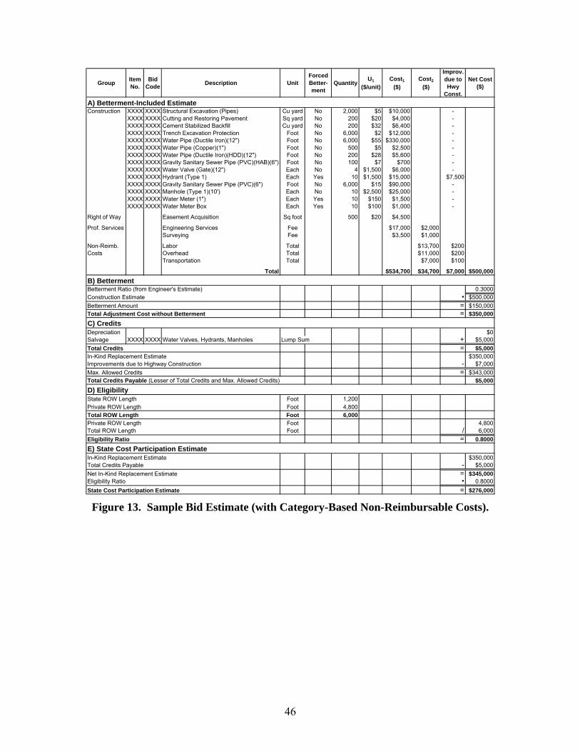
46
Group Item No.
Bid Code Description Unit
ForcedBetter-ment
QuantityU1
($/unit)Cost1
($)Cost2
($)
Improv. due to Hwy
Const.
Net Cost($)
A) Betterment-Included EstimateConstruction XXXX XXXX Structural Excavation (Pipes) Cu yard No 2,000 $5 $10,000 -
XXXX XXXX Cutting and Restoring Pavement Sq yard No 200 $20 $4,000 -XXXX XXXX Cement Stabilized Backfill Cu yard No 200 $32 $6,400 -XXXX XXXX Trench Excavation Protection Foot No 6,000 $2 $12,000 -XXXX XXXX Water Pipe (Ductile Iron)(12") Foot No 6,000 $55 $330,000 -XXXX XXXX Water Pipe (Copper)(1") Foot No 500 $5 $2,500 -XXXX XXXX Water Pipe (Ductile Iron)(HDD)(12") Foot No 200 $28 $5,600 -XXXX XXXX Gravity Sanitary Sewer Pipe (PVC)(HAB)(6") Foot No 100 $7 $700 -XXXX XXXX Water Valve (Gate)(12") Each No 4 $1,500 $6,000 -XXXX XXXX Hydrant (Type 1) Each Yes 10 $1,500 $15,000 $7,500XXXX XXXX Gravity Sanitary Sewer Pipe (PVC)(6") Foot No 6,000 $15 $90,000 -XXXX XXXX Manhole (Type 1)(10') Each No 10 $2,500 $25,000 -XXXX XXXX Water Meter (1") Each Yes 10 $150 $1,500 -XXXX XXXX Water Meter Box Each Yes 10 $100 $1,000 -
Right of Way Easement Acquisition Sq foot 500 $20 $4,500
Prof. Services Engineering Services Fee $17,000 $2,000Surveying Fee $3,500 $1,000
Non-Reimb. Labor Total $13,700 $200Costs Overhead Total $11,000 $200
Transportation Total $7,000 $100
Total $534,700 $34,700 $7,000 $500,000B) BettermentBetterment Ratio (from Engineer's Estimate) 0.3000Construction Estimate • $500,000Betterment Amount = $150,000Total Adjustment Cost without Betterment = $350,000C) CreditsDepreciation $0Salvage XXXX XXXX Water Valves, Hydrants, Manholes Lump Sum + $5,000Total Credits = $5,000In-Kind Replacement Estimate $350,000Improvements due to Highway Construction - $7,000Max. Allowed Credits = $343,000Total Credits Payable (Lesser of Total Credits and Max. Allowed Credits) $5,000D) EligibilityState ROW Length Foot 1,200Private ROW Length Foot 4,800Total ROW Length Foot 6,000Private ROW Length Foot 4,800Total ROW Length Foot / 6,000Eligibility Ratio = 0.8000E) State Cost Participation EstimateIn-Kind Replacement Estimate $350,000Total Credits Payable - $5,000Net In-Kind Replacement Estimate = $345,000Eligibility Ratio • 0.8000State Cost Participation Estimate = $276,000 Figure 13. Sample Bid Estimate (with Category-Based Non-Reimbursable Costs).

47
Group Item No.
Bid Code Description Unit
ForcedBetter-ment
QuantityU1
($/unit)Cost1
($)Cost2
($)
Improv. due to Hwy
Const.
Net Cost($)
A) Betterment-Included Final BillConstruction XXXX XXXX Structural Excavation (Pipes) Cu yard No 5,625 $5 $28,125 -
XXXX XXXX Cutting and Restoring Pavement Sq yard No 200 $20 $4,000 -XXXX XXXX Cement Stabilized Backfill Cu yard No 200 $32 $6,400 -XXXX XXXX Trench Excavation Protection Foot No 7,000 $2 $14,000 -XXXX XXXX Water Pipe (Ductile Iron)(12") Foot No 7,000 $55 $385,000 -XXXX XXXX Water Pipe (Copper)(1") Foot No 500 $5 $2,500 -XXXX XXXX Water Pipe (Ductile Iron)(HDD)(12") Foot No 900 $28 $25,200 -XXXX XXXX Gravity Sanitary Sewer Pipe (PVC)(HAB)(6") Foot No 100 $7 $700 -XXXX XXXX Water Valve (Gate)(12") Each No 4 $1,500 $6,000 -XXXX XXXX Hydrant (Type 1) Each Yes 10 $1,500 $15,000 $7,500XXXX XXXX Gravity Sanitary Sewer Pipe (PVC)(6") Foot No 7,000 $15 $105,000 -XXXX XXXX Manhole (Type 1)(10') Each No 10 $2,500 $25,000 -XXXX XXXX Water Meter (1") Each Yes 10 $150 $1,500 -XXXX XXXX Water Meter Box Each Yes 10 $100 $1,000 -
Right of Way Easement Acquisition Sq foot 500 $20 $4,500 $0
Prof. Services Engineering Services Fee $17,000 $2,000Surveying Fee $3,500 $1,000
Non-Reimb. Labor Total $18,000 $200Costs Overhead Total $14,425 $200
Transportation Total $9,000 $100
Total $644,425 $44,425 $7,000 $600,000B) BettermentBetterment Ratio (from Engineer's Estimate) 0.3000Final Bill Amount • $600,000Betterment Amount = $180,000Total Adjustment Cost without Betterment = $420,000C) CreditsDepreciation $0Salvag. Mat. XXXX XXXX Water Valves, Hydrants, Manholes Lump Sum + $5,000Total Credits = $5,000Total Adjustment Cost without Betterment $420,000Improvements due to Highway Construction - $7,000Max. Credits Allowed = $413,000Total Credits Payable (Lesser of Total Credits and Max. Allowed Credits) $5,000D) State Cost ParticipationTotal Adjustment Cost without Betterment $420,000Credits - $5,000Net In-Kind Replacement Estimate = $415,000Eligibility Ratio (from Estimate) • 0.8000State Cost Participation = $332,000
Figure 14. Sample Final Bill (with Category-Based Non-Reimbursable Costs).
A more detailed description of the columns and sections in Figure 9 through Figure 14 follows:
• Group. This column represents the highest level of aggregation for work items. Following the example in Figure 1, the sample includes three groups: Construction, Right of Way, and Professional Services.
• Item No. This column represents the item number according to the standard specification (three digits) or special specification (four digits) used. For simplicity and for illustration purposes, Figure 9 through Figure 14 show all item numbers as “XXXX.” The example includes 14 work items for the betterment-included estimate and 14 work items for the in-kind replacement estimate. As mentioned before, ROW acquisition and professional services are accounted for separately. In the case of ROW acquisition, the assumption is that it is possible to include all reimbursable items in a per-square foot ROW acquisition unit cost. If needed, ROW acquisition costs could be more

48
disaggregated. In the case of engineering services, the example simply shows a fee, although, if needed, a finer level of disaggregation might be possible.
• Bid Code. This column represents the bid code associated with a work item. In general, the bid code is a four-digit number. For simplicity and for illustration purposes, Figure 9 through Figure 14 show all bid codes as “XXXX.”
• Description. This column represents the item description.
• Unit. This column represents the item unit of measurement.
• Forced Betterment. This column represents a flag that highlights whether a specific item is a forced betterment item and is, therefore, eligible for reimbursement. For example, Figure 9 shows hydrants and the 1-inch water meters and the corresponding meter boxes are forced betterment items.
• Quantity. This column represents the quantity of the item in the previously given units.
• U1. This column represents reference unit costs, i.e., unit prices a contractor would charge if submitting a bid for the utility relocation work. U1 includes all direct costs, indirect costs, and profit.
• Cost1. This column represents the total item cost, which results from multiplying quantities by the corresponding reference unit costs U1. Adding all the values in column Cost1 provides the total cost, e.g., $474,700 (betterment-included engineer’s estimate) or $341,200 (in-kind replacement engineer’s estimate). Notice these totals include ROW acquisition and professional services.
• U2. This column represents “non-reimbursable unit costs,” i.e., the component of the reference unit costs in column U1 that would not be reimbursable, according to the guidelines in the Utility Manual ( 2).
• Cost2. This column represents the total non-reimbursable item cost, which results from multiplying quantity by the corresponding “non-reimbursable unit cost” U2 and adding those costs (if using unit cost-based non-reimbursable costs—Figure 9 and Figure 11) or from adding all the non-reimbursable cost categories (if using category-based non-reimbursable costs—Figure 12 and Figure 14). For example, in Figure 9 the total non-reimbursable cost estimate is $34,700 (betterment-included engineer’s estimate) and $33,200 (in-kind replacement engineer’s estimate).
• U1 – U2. This column represents the difference between U1 and U2, i.e., the portion of U1 that may be reimbursable.
• Improvements due to Highway Construction. This column represents costs associated with utility relocation elements that require an improvement as a result of the highway construction project. In Figure 9, the assumption is that $7,500 (associated with five

49
hydrants) represents improvements due to highway construction, of which $7,000 would be reimbursable.
• Net Cost. This column represents the total reimbursable amount, which results from multiplying quantity by the corresponding U1 – U2 value, or from calculating Cost1 – Cost2. Adding all the values in column Net Cost provides the total reimbursable amount, e.g., $440,000 (betterment-included engineer’s estimate) or $308,000 (in-kind replacement engineer’s estimate).
• Betterment Calculation. This section determines the portion of the estimate that reflects an elective betterment, which is therefore not eligible for reimbursement. Following Figure 1, the betterment ratio is the dollar amount of elective betterments (calculated as the difference between the betterment-included estimate and the in-kind replacement estimate, in this case $132,000) divided by the dollar amount of the betterment-included estimate ($440,000). In this example, the betterment ratio is 0.30.
• Credits. This section determines whether any credits are due to the project, including accrued depreciation and salvageable materials. As mentioned previously, credit for accrued depreciation applies in the case of major utility facilities such as buildings, pumping stations, plants, and similar operational units. In this example, the assumption is that no accrued depreciation credits apply. In the case of salvage materials, the example assumes Item 497, “Sale of Salvageable Material,” applies, which enables the measurement and payment of salvageable materials, including any re-stocked materials, as a lump sum item ( 44). The calculation of total payable credits assumes the total of all credits cannot exceed the total relocation costs minus the cost of improvements needed by the highway construction ( 24).
• Eligibility Calculation. This section determines the portion of the estimate that is eligible for cost reimbursement based on compensable interest grounds. As mentioned previously in Chapter 2, TxDOT normally determines eligibility by measuring proportional property rights along the centerline of the existing utility facility. In this example, the project is 4,800 feet on private ROW and 1,200 feet on state ROW, for a total project length of 6,000 feet. Further, the assumption is the utility currently occupies the 1,200 feet on state ROW by permit and therefore does not have a compensable interest on that section of the installation. The eligibility ratio is therefore 0.80.
It may be worth noting that due to differences in the nature of the process, a unit cost approach requires a different set of cost verification tools than other approaches, such as a lump sum approach. These tools may include standardized field inspection requirements and cost reporting structures, a database of historical unit cost data for comparison, and adjustment factors to reflect differences across conditions.


51
CHAPTER 4. WATER AND SANITARY SEWER SPECIFICATIONS
INTRODUCTION
The researchers reviewed a sample of TxDOT water main and sanitary sewer special specifications, as well as associated bid items and unit bid prices. This chapter summarizes the result of the analysis and concludes with a proposed framework for standardized water and sanitary sewer specifications at TxDOT. Note: This chapter makes frequent references to existing TxDOT special specification titles, content, and corresponding bid items. Those references are exact as they appear in the TxDOT databases (to the extent possible, within double quotes or in smaller font size), including typographical errors and inconsistencies in wording and formatting.
SPECIAL SPECIFICATION SAMPLE
The number of 2004 water main and sanitary sewer special specifications at TxDOT is still relatively low (although this situation is changing as the number of highway construction projects that use 2004 specifications increases). For this reason, the researchers focused on 1993 special specifications. From a total of nearly 6,000 1993 special specifications available on the TxDOT website, the researchers identified 283 water and sanitary sewer special specifications (using “water,” “sanitary,” “wastewater,” and “waste water” as key words to filter specification titles). Table 8 lists the special specification titles gathered and the corresponding number of specifications found. Of the 283 water and sanitary sewer special specifications identified, the researchers selected 26 specifications that appeared to represent a cross section of the entire set and spanned the period from 1994 to 2004. Table 9 lists the special specifications selected, along with a summary of the total number of utility-related bid items, the corresponding control section job (CSJ) number, the number of bid items and extended amount for one of the contracts associated with the CSJ, and the relative impact of the utility work in terms of number of bid items and extended amount. For example, Special Specification 3513 (Water Mains) had a total of 140 utility bid items identified during the project development process. The corresponding CSJ was 027107248. One of the contracts associated with this CSJ had 50 utility-related bid items and the corresponding extended amount was $3,053,465. The total number of bid items associated with that contract was 562, and the winning bid had a total extended amount of $250,411,715. The impact of the utility work on the total contract was 9 percent in terms of number of bid items (i.e., 50 ÷ 562) and slightly over 1 percent in terms of extended dollar amount (i.e., $3,053,465 ÷ $250,411,715).
52
Table 8. Year 1993 Water and Sanitary Sewer Special Specification Titles at TxDOT. Special Specification Title Count Special Specification Title Count
8-Inch Water Main Lowering 1 Sanitary Sewers (Concrete Encasement) 1 Adjustment Of Wastewater Lateral 1 Sanitary Sewers (Wetlands) 1 Adjustment of Wastewater Lateral and Mainline Cleanouts
2 Testing and Inspection of Completed Sanitary Sewer Lines
3
Adjustment of Water Meter Box and Flush Point
2 Testing and Sterilization of Completed Water Lines
3
Bexar Met Water Mains and Service Lines 1 Vertical Adjustment Of Water Valve Cover 1 By-Pass Pumping (Sanitary Sewer) 1 Vertical Adjustment of Water Valve Cover and
Valve Stack 5
Cut and Plug Water Main (8 In) 1 Wastewater Piping and Appurtenances 1 Dewatering 3 Wastewater Treatment Plant 2 Dewatering in Contaminated Groundwater 1 Water and Sanitary Sewer Systems 1 Disinfection of Waterlines 2 Water and Wastewater Infrastructures and
Appurtenances 1
El Paso Water Utilities 1 Water and Wastewater Mains 3 Low Pressure Air Test - Sanitary Sewer Lines 1 Water Line 1 Manholes (Sanitary Sewer) 4 Water Line and Sanitary Sewer Line 1 One Inch Water Service 1 Water Line Casing 3 Polyvinyl Chloride (PVC) Pipe for Waterlines 2 Water Lines and Appurtenances 1 Post-Construction Television Inspection of Sanitary Sewer
2 Water Main 1
Potable Water Distribution System and Sanitary Sewer Replacement
1 Water Main and Sanitary Sewers 1
Pumping, Storage and Disposal of Contaminated Water
1 Water Main Appurtenances 1
PVC Pipe for Sanitary Sewers 2 Water Main Construction 1 Recycled Water Mains 1 Water Mains 36 Relocate Sanitary Sewer 1 Water Mains & Sanitary Sewer 1 Relocating Sanitary Sewer Pump 1 Water Mains and Sanitary Sewers 1 Salvaging Water Lines, Sanitary Sewer Lines, Fire Hydrants, Valves and Fittings
1 Water Mains and Appurtenances 2
Sanitary Sewer (By-Pass Pumping) 2 Water Mains and Sanitary Sewer 1 Sanitary Sewer (Cleaning Manholes and Mains)
2 Water Mains and Sanitary Sewers 48
Sanitary Sewer (Manhole Rehabilitation) 4 Water Mains and Service Lines 33 Sanitary Sewer (Point Repair) 1 Water Mains and Service Lines in New
Braunfels 1
Sanitary Sewer (Rehabilitation Of Lines) 2 Water Mains and Wastewater Appurtenances 17 Sanitary Sewer (Repair) 1 Water Mains, Sanitary Sewers and Apparatus 3 Sanitary Sewer (Television Inspection) 3 Water Service 2 Sanitary Sewer Lift Station 1 Water System 1 Sanitary Sewer Mains 3 Water Systems 1 Sanitary Sewer Service 1 Water Tank and Pump 7 Sanitary Sewer System 2 Water, Reclaim Water, and Sanitary Sewer
Systems 1
Sanitary Sewers 40
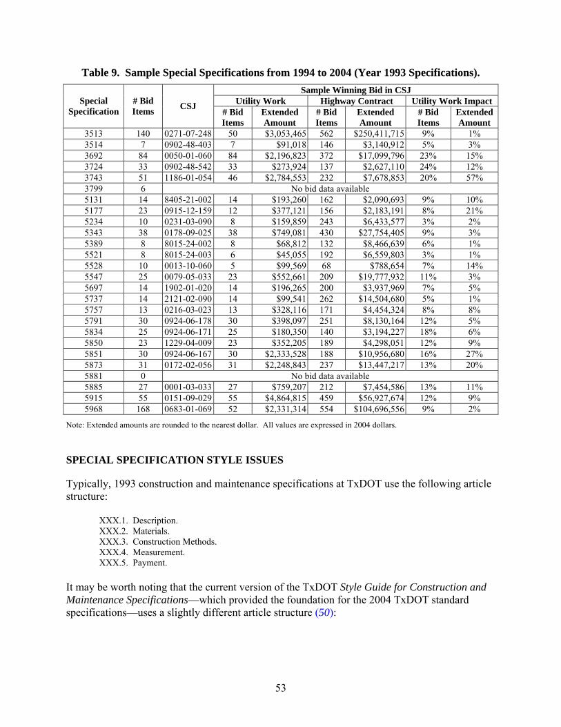
53
Table 9. Sample Special Specifications from 1994 to 2004 (Year 1993 Specifications). Sample Winning Bid in CSJ
Utility Work Highway Contract Utility Work Impact Special Specification
# Bid Items CSJ # Bid
Items Extended Amount
# Bid Items
Extended Amount
# Bid Items
Extended Amount
3513 140 0271-07-248 50 $3,053,465 562 $250,411,715 9% 1% 3514 7 0902-48-403 7 $91,018 146 $3,140,912 5% 3% 3692 84 0050-01-060 84 $2,196,823 372 $17,099,796 23% 15% 3724 33 0902-48-542 33 $273,924 137 $2,627,110 24% 12% 3743 51 1186-01-054 46 $2,784,553 232 $7,678,853 20% 57% 3799 6 No bid data available 5131 14 8405-21-002 14 $193,260 162 $2,090,693 9% 10% 5177 23 0915-12-159 12 $377,121 156 $2,183,191 8% 21% 5234 10 0231-03-090 8 $159,859 243 $6,433,577 3% 2% 5343 38 0178-09-025 38 $749,081 430 $27,754,405 9% 3% 5389 8 8015-24-002 8 $68,812 132 $8,466,639 6% 1% 5521 8 8015-24-003 6 $45,055 192 $6,559,803 3% 1% 5528 10 0013-10-060 5 $99,569 68 $788,654 7% 14% 5547 25 0079-05-033 23 $552,661 209 $19,777,932 11% 3% 5697 14 1902-01-020 14 $196,265 200 $3,937,969 7% 5% 5737 14 2121-02-090 14 $99,541 262 $14,504,680 5% 1% 5757 13 0216-03-023 13 $328,116 171 $4,454,324 8% 8% 5791 30 0924-06-178 30 $398,097 251 $8,130,164 12% 5% 5834 25 0924-06-171 25 $180,350 140 $3,194,227 18% 6% 5850 23 1229-04-009 23 $352,205 189 $4,298,051 12% 9% 5851 30 0924-06-167 30 $2,333,528 188 $10,956,680 16% 27% 5873 31 0172-02-056 31 $2,248,843 237 $13,447,217 13% 20% 5881 0 No bid data available 5885 27 0001-03-033 27 $759,207 212 $7,454,586 13% 11% 5915 55 0151-09-029 55 $4,864,815 459 $56,927,674 12% 9% 5968 168 0683-01-069 52 $2,331,314 554 $104,696,556 9% 2%
Note: Extended amounts are rounded to the nearest dollar. All values are expressed in 2004 dollars.
SPECIAL SPECIFICATION STYLE ISSUES
Typically, 1993 construction and maintenance specifications at TxDOT use the following article structure:
XXX.1. Description. XXX.2. Materials. XXX.3. Construction Methods. XXX.4. Measurement. XXX.5. Payment.
It may be worth noting that the current version of the TxDOT Style Guide for Construction and Maintenance Specifications—which provided the foundation for the 2004 TxDOT standard specifications—uses a slightly different article structure ( 50):

54
XXX.1. Description. XXX.2. Materials. XXX 3. Equipment. XXX.4. Construction or Work Methods. XXX.5. Measurement. XXX.6. Payment.
A review of the special specifications listed in Table 9 reveals a wide range in specification styles. Roughly speaking, specifications fall under one of four style categories (Figure 15):
• Style 1. This style is the basic 1993 standard specification style with five articles.
• Style 2. This style is a variation of the standard specification style, where a table of contents is included at the beginning of the special specification document.
• Style 3. This style is a substantial variation of the standard specification style
characterized by many more articles than the standard five, followed by an attachment that normally includes general provisions and detailed construction specifications from a local jurisdiction.
• Style 4. This style is another substantial variation of the standard specification style
characterized by two or more sections, each one containing a variation of the standard specification style article structure.
Figure 15 also lists the special specifications from Table 8 that fall under each style category, along with the date associated with each specification (typically the date shown on the lower right corner of the specification) and the corresponding TxDOT district. An interesting observation is that earlier specifications (e.g., 5131 and 5177) tended to follow the standard specification style (Style 1) more closely than more recent specifications. According to information provided by ROW Division officials, this trend coincides with changes in policy that provided more flexibility to utility companies concerning the submission of utility relocation documentation. Another observation is that earlier specifications tended to focus on either water mains or sanitary sewers, but more recent specifications typically cover both water mains and sanitary sewers (and in at least one case, reclaimed water).

55
1. Description.2. Materials.3. Construction Methods.4. Measurement.5. Payment.
Style 1“Basic” 1993 TxDOT Specification Style
1. Description.2. Materials.3. Construction Methods.4. Measurement.5. Payment.
Table of Contents
Style 2“Basic” 1993 TxDOT Specification Style with Table of Contents
Examples:3513, “Water Mains” (05-2003), Houston District5343, “Water Mains” (05-1996), Houston District5547, “Water Mains and Service Lines” (04-1998), Fort Worth District5740, “Water Mains and Service Lines” (10-2000), Childress District5881, “Water Mains and Service Lines” (04-2002), Waco District
1. Description.2. Terminology.3. Materials.4. Construction Methods.5. Inspection and Testing.6. Sterilization of Potable Water Lines.7. Safety.8. Resolution of Conflicts.9. Measurement.10. Payment.
Style 3Unique Article Style, Attachment
Examples:3514, “Water Mains and Sanitary Sewers” (05-2003), Fort Worth District3692, “Water Mains and Sanitary Sewers” (03-2004), Bryan District3724, “Water Mains and Sanitary Sewers” (05-2004), Fort Worth District3743, “Water and Wastewater Mains” (07-2004), Austin District3799, “Water Mains and Sanitary Sewers” (10-2004), Fort Worth District5528, “Water Mains and Sanitary Sewers” (10-1997), Fort Worth District5697, “Water Mains” (06-2000), Austin District5850, “Water Main and Sanitary Sewers” (11-2001), Laredo District5873, “Water Mains and Sanitary Sewers” (03-2002), Fort Worth District5878, “Water Mains and Sanitary Sewers” (04-2002), Dallas District5915, “Water Mains and Sanitary Sewers” (09-2002), Austin District5968, “Water Mains and Sanitary Sewers” (01-2003), Austin District5973, “Water Mains and Wastewater Appurtenances” (03-2003), Dallas District
Examples:5131, “Water Mains” (11-1994), Pharr District5177, “Sanitary Sewers” (03-1995), San Antonio District5234, “Water Mains” (07-1995), Waco District5389, “Sanitary Sewers” (07-1996), El Paso District5521, “Sanitary Sewers” (09-1997), El Paso District
Attachment (e.g., specifications from a local jurisdiction)
1. Description.2. Materials.3. Construction Methods.4. Testing.5. Disinfection.6. Measurement.7. Payment.
Style 4Unique Article Style, Several Separate Sections, No Attachment
Examples:5600, “Water Mains and Sanitary Sewers” (05-1999), Laredo District5737, “Water Mains and Sanitary Sewers” (10-2000), El Paso District5757, “Sanitary Sewers” (01-2001), San Antonio District5791, “Water Mains & Sanitary Sewer” (05-2001), El Paso District5834, “Water Mains and Sanitary Sewer” (09-2001), El Paso District5851, “Water, Reclaim Water, and Sanitary Sewer Systems” (12-2001), El Paso District5885, “Water and Sanitary Sewer Systems” (05-2002), El Paso District
Section I
1. Description.2. Materials.3. Construction Methods.4. Testing.5. Measurement.6. Payment.
Section II
1. Description.2. Products.3. Execution.
Section III
Notes: Examples listed include specification number, specification title, date, and district. Specifications cover an 11-year period from 1994 to 2004. All specifications are year 1993 specifications.
Figure 15. Typical Styles of Water Main and Sanitary Sewer Special Specifications (1993 Specifications).

56
SPECIAL SPECIFICATION CONTENT, MEASUREMENT, AND PAYMENT ISSUES
Table 10 through Table 35 summarize the basic characteristics of each special specification analyzed, along with the corresponding bid items used during the letting process.
Table 10. Special Specification 3513, “Water Mains.”
Specifications Book 1993 Specification Date 05-2003 Use CSJ 0271-07-248 District Houston No. of Pages 73 Style 2 Local Specifications N/A Bid Items (140): ADJUSTING METER BOX AIR RELEASE & VACUUM RELIEF VALVE (2") BLOW OFF VALVE (2") BUTTERFLY VALVE (24") BUTTERFLY VALVE (30") BUTTERFLY VALVE (36") BUTTERFLY VALVE(CASTIRON)(16 IN) CASING (SPLT) (STL) (12 IN) CASING (STEEL)(14") CASING (STEEL)(16") CASING (STEEL)(20") CASING (STEEL)(6") CASING (STL) (18") CASING (STL) (24 IN) CASING(STL) (30 IN) CASING(STL) (42 IN) CUT AND PLUG WATER MAIN (12") CUT AND PLUG WATER MAIN (16 IN) CUT AND PLUG WATER MAIN (2 IN) CUT AND PLUG WATER MAIN (20") CUT AND PLUG WATER MAIN (24") CUT AND PLUG WATER MAIN (30") CUT AND PLUG WATER MAIN (36") CUT AND PLUG WATER MAIN (4 IN) CUT AND PLUG WATER MAIN (4") CUT AND PLUG WATER MAIN (6") CUT AND PLUG WATER MAIN (8") CUT AND PLUG WATER MAIN (8") EXTRA HAND EXCAVATION FIRE HYDRANT FIRE HYDRANT BRANCH (6") (OPEN CUT) FITTINGS (DUCTILE IRON) GATE VALVE (12" X 12") GATE VALVE (16") GATE VALVE (2 1/2") GATE VALVE (20") GATE VALVE (24") GATE VALVE (6") GATE VALVE (8") GATE VALVE AND BOX (12") GATE VALVE AND BOX (6") GATE VALVE AND BOX (8") GATE VALVE W/BOX (6") GATE VALVE(12") GATE VALVE(2") GATE VALVE(4") GATE VALVES (12") GATE VALVES (4")
GATE VALVES (8") JACK,TUN,BORE OR AUG (WTR MN)(PVC)(12") JACK,TUN,BORE OR AUG (WTR MN)(PVC)(6") JACK,TUN,BORE OR AUG (WTR MN)(PVC)(8") JACK,TUN,BORE OR AUG (WTR MN)(STL)(12") JACK,TUN,BORE OR AUG CASING (STL)(14") JACK,TUN,BORE OR AUG CASING (STL)(16") JACK,TUN,BORE OR AUG CASING (STL)(18") JACK,TUN,BORE OR AUG CASING (STL)(20") JACK,TUN,BORE OR AUG CASING (STL)(24") JACK,TUN,BORE OR AUG CASING (STL)(36") JACK,TUN,BORE OR AUG CASING(STL)(30") LOWERING WATER MAIN (12") LOWERING WATER MAIN (30") LOWERING WATER MAIN (36") LOWERING WATER MAIN (8") METER AND VAULT REMOVE AND RELOCATE EXISTING VALVE REMOVE AND RELOCATE METER AND BOX REMOVE FIRE HYDRANT REMOVE WATER MAIN (16") REMOVE WATER MAIN (2") REMOVE WATER MAIN (8") REMOVE WATER METER AND BOX REMOVE WATER VALVE AND BOX REMOVING AND SALVAGING FIRE HYDRANT SERVICE LINE (LONG SIDE)(1 1/2" TO 2") SERVICE LINE (LONG SIDE)(5/8" TO 1") SERVICE LINE (SHORT SIDE) (4") SERVICE LINE (SHORT SIDE)(1 1/2" TO 2") SERVICE LINE (SHORT SIDE)(3" TO 8") SERVICE LINE (SHORT SIDE)(5/8" TO 1") TAP SLEEVE AND VALVE (12" X 12") TAP SLEEVE AND VALVE (16" X 16") TAP SLEEVE AND VALVE (16" X 6") TAP SLEEVE AND VALVE (16"X 8") TAP SLEEVE AND VALVE (20" X 20") TAP SLEEVE AND VALVE (20" X 8") TAP SLEEVE AND VALVE (24" X 12") TAP SLEEVE AND VALVE (24" X 6") TAP SLEEVE AND VALVE (8" X 6") TAP SLEEVE AND VALVE (8" X 8") TAP SLEEVE AND VALVE W/BOX (16" X 16") TAP SLEEVE AND VALVE WITH BOX (8"X 2")
TAP SLEEVE AND VALVE(12"X6") TAPPING SLEEVE AND VALVE (12"X12") TAPPING SLEEVE AND VALVE (4"X12") WATER LINE TESTING AND STER WATER MAIN PIPE (DI)(16") WATER MAIN PIPE (DI)(20") WATER MAIN PIPE (DI)(24") WATER MAIN PIPE (DI)(30") WATER MAIN PIPE (DI)(36") WATER MAIN PIPE (FRP) (12 IN) WATER MAIN PIPE (FRP) (16 IN) WATER MAIN PIPE (FRP) (20 IN) WATER MAIN PIPE (FRP) (24 IN) WATER MAIN PIPE (FRP) (6 IN) WATER MAIN PIPE (FRP) (8 IN) WATER MAIN PIPE (PVC) (12IN) (C-900) WATER MAIN PIPE (PVC) (6") (C-900) WATER MAIN PIPE (PVC)(12 IN) WATER MAIN PIPE (PVC)(2 IN) WATER MAIN PIPE (PVC)(24 IN) WATER MAIN PIPE (PVC)(4 IN) WATER MAIN PIPE (PVC)(6 IN) WATER MAIN PIPE (PVC)(8 IN) WATER MAIN PIPE (STL) (12IN) WATER MAIN PIPE (STL) (36 IN) WATER MAIN PIPE (STL)(24") WATER MAIN PIPE (STL)(30") WATER MAIN PIPE(DI)(12 IN) WATER MAIN PIPE(DI, STL)(8") WATER MAIN PIPE(PVC)(16 IN) WATER MAIN PIPE(PVC)(8IN) WATER MAIN PIPE(PVC)(SCHD 40) (2 1/2") WATER MAIN PIPE(PVC)(SCHD 40) (2") WATER MAIN PIPE(PVC)(SCHD 40) (4") WATER MAIN PIPE(STL)(6IN) WATER MAIN PIPE(STL)(8IN) WET CONNECTION (12"X12") WET CONNECTION (2") WET CONNECTION (4") WET CONNECTION (8"X12") WET CONNECTIONS (12") WET CONNECTIONS (16 IN) WET CONNECTIONS (2") WET CONNECTIONS (20") WET CONNECTIONS (24") WET CONNECTIONS (30") WET CONNECTIONS (6") WET CONNECTIONS (8")

57
Table 11. Special Specification 3514, “Water Mains and Sanitary Sewers.”
Specifications Book 1993 Specification Date 05-2003 Use CSJ 0902-48-403 District Fort Worth No. of Pages 79 Style 3 Local Specifications North Central Texas Council of Governments Bid Items (7): FIRE HYDRANTS FITTINGS (DUCTILE IRON) FITTINGS (GATE VALVE AND BOX)(16 INCH)
FITTINGS (GATE VALVE AND BOX)(6 INCH) WATER PIPE (PVC)(16 INCH)(DR-18) WATER PIPE (PVC)(6 INCH)(DR-18)
WATER SERVICE CONNECTION (METER)(RELOC)
Table 12. Special Specification 3692, “Water Mains and Sanitary Sewers.”
Specifications Book 1993 Specification Date 03-2004 Use CSJ 0050-01-060 District Bryan No. of Pages 208 Style 3 Local Specifications City of College Station Bid Items (84): 1" AIR RELEASE 12" M.J. CAP 12" M.J. GATE VALVE 12" SANITARY SEWER 12" WATER LINE 12" X 11.25 M.J. BEND 12" X 12" M.J. CROSS 12" X 12" M.J. TEE 12" X 22.5 M.J. BEND 12" X 45 M.J. BEND 12" X 6" M.J. REDUCER 12" X 6" M.J. TEE 12" X 8" M.J. TEE 15" SANITARY SEWER 16" CASING BY OPEN CUT-SANITARY SEWER 16" CASING BY OPEN CUT-WATER LINE 16" WATER LINE 16" X 12" M.J. REDUCER 16" X 16" M.J. TEE 18" M.J. BUTTERFLY VALVE 18" WATER LINE 18" X 12" M.J. REDUCER 18" X 18" M.J. TEE 18" X 22.5 M.J. BEND 18" X 8" M.J. TEE 18" X11.25 M.J. BEND 18"X 12" M.J. TEE 2" DOUBLE WATER SERVICE
2" SINGLE WATER SERVICE 2" WATER METER 21" RCP CASING BY OPEN CUT 24" BUTTERFLY M.J. VALVE 24" CASING BY BORE-SANITARY SEWER 24" CASING BY BORE-WATER LINE 24" CASING BY OPEN CUT 24" RCP CASING BY OPEN CUT 24" WATER LINE 24" X 11.25 M.J. BEND 24" X 12" M.J. REDUCER 24" X 24" M.J. TEE 24" X 6" M.J. TEE 3" WATER LINE 3" WATER METER 30" CASING BY BORE-SANITARY SEWER 30" CASING BY BORE-WATER LINE 30" CASING BY OPEN CUT 36" CASING BY OPEN CUT 4" SANITARY SEWER 6" BLOWOFF ASSEMBLY 6" M.J. GATE VALVE 6" SANITARY SEWER 6" WATER LINE 6" X 45 M.J. BEND 8" M.J. GATE VALVE 8" SANITARY SEWER 8" SANITARY SEWER BY PIPE BURST 8" WATER LINE
8" X 45 M.J. BEND 8" X 90 M.J. BEND ABANDON EXISTING MANHOLES ADJUST EX. FIRE HYDRANT LOCATION CONNECT TO EX. 16" LINE CONNECT TO EX. 18" LINE CONNECT TO EX. 24" LINE CONNECT TO EXISTING 12" LINE CONNECT TO EXISTING 3" LINE CONNECT TO EXISTING 6" LINE CONNECT TO EXISTING 8" LINE DRY RIP RAP CHANNEL LINING GROUT FILL EXISTING 12" WATER LINE GROUT FILL EXISTING 15" SANITARY SWR GROUT FILL EXISTING 18" WATER LINE GROUT FILL EXISTING 24" WATER LINE GROUT FILL EXISTING 6" SANITARY SWR GROUT FILL EXISTING 6" WATER LINE GROUT FILL EXISTING 8" SANITARY SWR GROUT FILL EXISTING 8" WATER LINE SANITAY SWR SERVICE CONNECTION(4"OR6") SEWER MANHOLE SQUARE SEWER MANHOLE TYPE 1 FIRE HYDRANT ASSEMBLY TYPE 2 FIRE HYDRANT ASSEMBLY TYPE 3 FIRE HYDRANT ASSEMBLY UNCASED BORE (12" & 8")

58
Table 13. Special Specification 3724, “Water Mains and Sanitary Sewers.”
Specifications Book 1993 Specification Date 05-2004 Use CSJ 0902-48-542 District Fort Worth No. of Pages 106 Style 3 Local Specifications North Central Texas Council of Governments Bid Items (33): CONC ENCASEMENT CUT,PLUG,BLOCK EXIST WAT LN CUT-IN VALVE (COMPL)(8") DROP MANHOL(SAN SEW)(4FT DIA)(EX DEPTH) DROP MANHOLE (SAN SEW)(4 FT DIA)(0-8FT) DUCTILE IRON FITTINGS FIRE HYDRANT (COMPL IN PLACE) FIRE HYDRANT (REMOVE & RESET) FIRE HYDRANT (REMOVE & SALVAGE) GATE VALVE & BOX (COMPL)(6") GATE VALVE & BOX (COMPL)(8")
GATE VALVE & BOX(COMPL)(4") GATE VALVE (REMOVE & SALVAGE) JACK OR BOR PIPE (CASING)(STL)(12") JACK OR BOR PIPE (CASING)(STL)(18") MANHOLE (REMOV TOP, CAP & ABANDON) MANHOLE (SAN SEW)(4 FT DIA)(0-8 FT) MANHOLE (SAN SEW)(4 FT DIA)(EXT DEPTH) PIPE (SAN SEW)(PVC)(SDR 35)(6")(0-8 FT) PIPE (SAN SEW)(PVC)(SDR 35)(6")(8-10FT) PIPE (SAN SEW)(PVC)(SDR 35)(6")(IN CSG) PIPE (SAN SEW)(PVC)(SDR 35)(8")(0-8 FT) PIPE (SAN SEW)(PVC)(SDR 35)(8")(8-10FT)
PIPE (WAT)(PVC)(DR 18)(C900/CL 150)(4") PIPE (WAT)(PVC)(DR 18)(C900/CL 150)(6") PIPE (WAT)(PVC)(DR 18)(C900/CL 150)(8") PIPE(WAT)(PVC)(DR18 C900/CL150 6")(CSG) PIPE(WAT)(PVC)(DR18 C900/CL150 8")(CSG) PLUG ABANDONED WAT LN TAPPING SLV & VALV & BOX(COMPL)(6"X6") TAPPING SLV & VALV & BOX(COMPL)(8"X6") WATER SERV TAP (COMPL)(2") WATER SERV TAP (COPPER)(TY K)(2")
Table 14. Special Specification 3743, “Water and Wastewater Mains.”
Specifications Book 1993 Specification Date 07-2004 Use CSJ 1186-01-054 District Austin No. of Pages 125 Style 3 Local Specifications City of Austin Bid Items (51): ABANDONMENT OF EXIST WASTEWATER MH ABANDONMENT OF EXISTING MANHOLES ADJUST FIRE HYDRANT ADJUST VALVE ADJUST WATER METER BRACING OF POWER POLES DRAIN VALVE ASSEMBLY (TY W) ENCASEMENT PIPE (20") (STL) ENCASEMENT PIPE (24") (STL) ENCASEMENT PIPE (36") (STL) FIRE HYDRANT HORZNTL DIRECTIONAL DRILL(24")(TY W) INSTAL RECON SERV TO NEW WW PIPE INSTALL RECON WTR SERV TO NEW WTR PIPE JACK/BORE PIPE (20") (STL) JACK/BORE PIPE (20") (STL) (WW) JACK/BORE PIPE (24") (STL) (WW)
JACK/BORE PIPE (24")(DI CL250)NO CASNG JACK/BORE PIPE (36") (STL) JACK/BORE PIPE(12")(PVC) NO CASNG (WW) JACK/BORE PIPE(20")(STL)SLUDGE FORCE MANUAL/AUTOMATIC AIR RELEASE ASSEMBLY NEW MANHOLE (DEPTH 8' OR LESS) (48") NEW MANHOLE (DEPTH OVER 8')(48") NEW MANHOLE (DEPTH OVER 8')(48") NEW MANHOLE (DEPTH OVER 8')(72") NEW MANHOLE (DEPTH OVER 8')(72") NEW MANHOLE(DEPTH OVER 8')(48")(DROP) NEW MANHOLE(DEPTH OVER 8')(48")(DROP) PIPE (12") DI CL 350 (W) PIPE (12") PVC (ASTM D3034 SDR-26)(WW) PIPE (12")DI CL350 SLUDGE FORCE MAIN PIPE (16") DI CL 250 (W)
PIPE (18") PVC (ASTM F679) (WW) PIPE (24") DI CL 250 (W) PIPE (24") DI CL 350 RJP (W) PIPE (36") FRPM (ASTM D3262) (WW) PIPE (6") DI CL 350 (W) PIPE (8") DI CL 350 (W) RECON OF EXISTING WATER SERVICE REHAB EXIST MH ADJUST MH COVER REHAB EXIST MH ADJUST MH COVER, COND A SPLIT ENCASEMENT PIPE (18") (STL) SPLIT ENCASEMENT PIPE (30") (STL) TAPPING SLEEVE & VALVE (8"X 8") TRENCH SAFETY SYSTEM VALVE (GATE) 12" DIA VALVE (GATE) 16" DIA VALVE (GATE) 24" DIA VALVE (GATE) 6" DIA VALVE (GATE) 8" DIA

59
Table 15. Special Specification 3799, “Water Mains and Sanitary Sewers.”
Specifications Book 1993 Specification Date 10-2004 Use CSJ 1068-01-187 District Fort Worth No. of Pages 80 Style 3 Local Specifications North Central Texas Council of Governments Bid Items (6): FIRE HYDRANT JACK OR BORING PIPE (18"-30" RCP)(CL 5)
PIPE (10" PVC)(SDR-26) PIPE (16" DI)(CL 51)
PIPE (8" DI)(CL 51) PIPE (8" PVC)(SDR-35)
Table 16. Special Specification 5131, “Water Mains.”
Specifications Book 1993 Specification Date 11-1994 Use CSJ 8405-21-002: Reconstruct city street in the vicinity of Canton Rd,
City of Edinburg District Pharr District No. of Pages 20 Style 1 Local Specifications N/A Bid Items (14): CASING (STEEL)(16 IN) CASING (STEEL)(24 IN) FIRE HYDRANT WITH VALVE AND BOX (6 IN) GATE, VALVE & BOX (CI)( 8 IN) GATE, VALVE & BOX (CI)(12 IN)
PIPE WATER MAIN (PVC)( 8 IN) PIPE WATER MAIN (PVC)(12 IN) REMOVING AND RELOCATING FIRE HYDRANTS REMOVING WATER MAINS ( 2 IN) REMOVING WATER MAINS ( 6 IN)
REMOVING WATER MAINS ( 8 IN) REMOVING WATER MAINS (12 IN) SERV LINE (LONG SIDE)(3/4") SERV LINE (SHORT SIDE)(3/4")

60
Table 17. Special Specification 5177, “Sanitary Sewers.”
Specifications Book 1993 Specification Date 03-1995 Use CSJ 0072-12-153, etc., 0915-12-158, etc., 0915-12-159, etc. District San Antonio No. of Pages 15 Style 1 Local Specifications N/A Bid Items (23): SAN SEWER (10 IN) SAN SEWER (10 IN)(JACK OR BORE) SAN SEWER (12 IN) SAN SEWER (18 IN) SAN SEWER (18 IN)(JACK OR BORE) SAN SEWER (20")(JACK, BORE OR TUNNEL) SAN SEWER (36")(JACK, BORE OR TUNNEL) SAN SEWER (6 IN)(LATERAL SERV CONN) SAN SEWER (8 IN)
SAN SEWER (ABANDON MANHOLE) SAN SEWER (ADJUST MANHOLE) SAN SEWER (CONC CRADLE) SAN SEWER (CONC ENCASEMENT) SAN SEWER (CONCRETE DRIVEWAY) SAN SEWER (CUT AND RESTORE PVMT) SAN SEWER (FLOWABLE BACKFILL) SAN SEWER (GROUT FOR ABANDON 18" MAIN)
SAN SEWER (MANH)(RING & COVER)WTR TIGHT SAN SEWER (SELECT BEDDING) SAN SEWER (TRENCH EXCAV PROTECTION) SAN SEWER MANHOLE (COMPL) SAN SEWER MANHOLE (COMPL)(0'-6') SAN SEWER(SELECT BEDDING)(CLEAN GRAVEL)
Table 18. Special Specification 5234, “Water Mains.”
Specifications Book 1993 Specification Date 07-1995 Use CSJ 0231-03-090 District Waco No. of Pages 13 Style 1 Local Specifications N/A Bid Items (10): CASING (STEEL)(16") CASING (STEEL)(20") GATE VALVE (12") GATE VALVE (8")
JACK OR BORE CASING (STEEL)(16") JACK OR BORE CASING (STEEL)(20") PIPE WATER MAIN (DI)(12")
PIPE WATER MAIN (DI)(8") SAND BACKFILL (WATER MAIN) SELECT BEDDING

61
Table 19. Special Specification 5343, “Water Mains.”
Specifications Book 1993 Specification Date 05-1996 Use CSJ 0178-09-025 District Houston No. of Pages 80 Style 2 Local Specifications N/A Bid Items (38): ADJUSTING MANHOLES (WATER MAIN) ADJUSTING VALVE BOXES BUTTERFLY VALVE W/BOX (24") CASING(STL)(18") CASING(STL)(36") CUT AND PLUG WATER MAIN (12") CUT AND PLUG WATER MAIN (24") CUT AND PLUG WATER MAIN (8") FIRE HYDRANT GATE VALVE W/BOX (12") GATE VALVE W/BOX (24") GATE VALVE W/BOX (4") GATE VALVE W/BOX (6") GATE VALVE W/BOX (8")
JACK,BORE,TUN OR AUG (WTR MN)(DI) (24") JACK,BORE,TUN OR AUG (WTR MN)(PVC)(12") JACK,BORE,TUN OR AUG (WTR MN)(STL)(12") JACK,BORE,TUN OR AUG (WTR MN)(STL)(24") JACK,BORE,TUN OR AUG CAS(.531" STL) 36" JACK,BORE,TUN OR AUG CASING (STL)(18") JACK,BORE,TUN OR AUG CASING (STL)(36") PIPE WATER MAIN (DUCT IRON)(24") PIPE WATER MAIN (PVC)(12") PIPE WATER MAIN (PVC)(4") PIPE WATER MAIN (PVC)(6")
PIPE WATER MAIN (PVC)(8") PIPE WATER MAIN (STL)(12") PIPE WATER MAIN (STL)(24") REMOVE VALVE W/BOXES REMOVING & SALVAGING WATER METERS REMOVING FIRE HYDRANT TAPPING SLEEVE & VALVE W/BOX(12" X 6") TAPPING SLEEVE & VALVE W/BOX(24" X 12") TAPPING SLEEVE & VALVE W/BOX(24" X 24") TAPPING SLEEVE & VALVE W/BOX(4" X 4") WET CONNECTION (12") WET CONNECTION (24") WET CONNECTION (8")
Table 20. Special Specification 5389, “Sanitary Sewers.”
Specifications Book 1993 Specification Date 07-1996 Use CSJ 8015-24-002 District El Paso No. of Pages 12 Style 1 Local Specifications N/A Bid Items (8): SANITARY SEWER MANHOLE (COMPL)(TY A) SANITARY SEWER MANHOLE (COMPL)(TY B)
SANITARY SEWER MANHOLE (COMPL)(TY D) SANITARY SEWER PIPE (12")(SDR-35) SANITARY SEWER PIPE (18")(PVC)
SANITARY SEWER PIPE (8")(SDR-35) SEWER SERVICE CONNECTION (4") SEWER SERVICE CONNECTION (6")
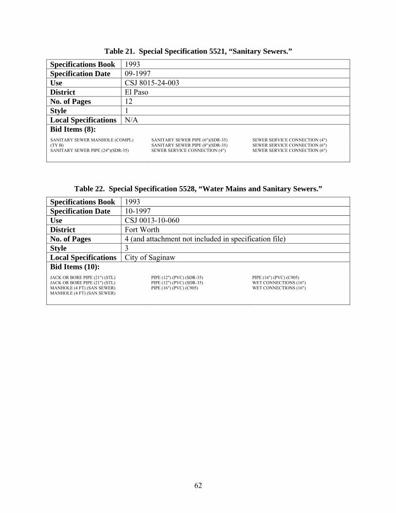
62
Table 21. Special Specification 5521, “Sanitary Sewers.”
Specifications Book 1993 Specification Date 09-1997 Use CSJ 8015-24-003 District El Paso No. of Pages 12 Style 1 Local Specifications N/A Bid Items (8): SANITARY SEWER MANHOLE (COMPL) (TY B) SANITARY SEWER PIPE (24")(SDR-35)
SANITARY SEWER PIPE (6")(SDR-35) SANITARY SEWER PIPE (8")(SDR-35) SEWER SERVICE CONNECTION (4")
SEWER SERVICE CONNECTION (4") SEWER SERVICE CONNECTION (6") SEWER SERVICE CONNECTION (6")
Table 22. Special Specification 5528, “Water Mains and Sanitary Sewers.”
Specifications Book 1993 Specification Date 10-1997 Use CSJ 0013-10-060 District Fort Worth No. of Pages 4 (and attachment not included in specification file) Style 3 Local Specifications City of Saginaw Bid Items (10): JACK OR BORE PIPE (21") (STL) JACK OR BORE PIPE (21") (STL) MANHOLE (4 FT) (SAN SEWER) MANHOLE (4 FT) (SAN SEWER)
PIPE (12") (PVC) (SDR-35) PIPE (12") (PVC) (SDR-35) PIPE (16") (PVC) (C905)
PIPE (16") (PVC) (C905) WET CONNECTIONS (16") WET CONNECTIONS (16")
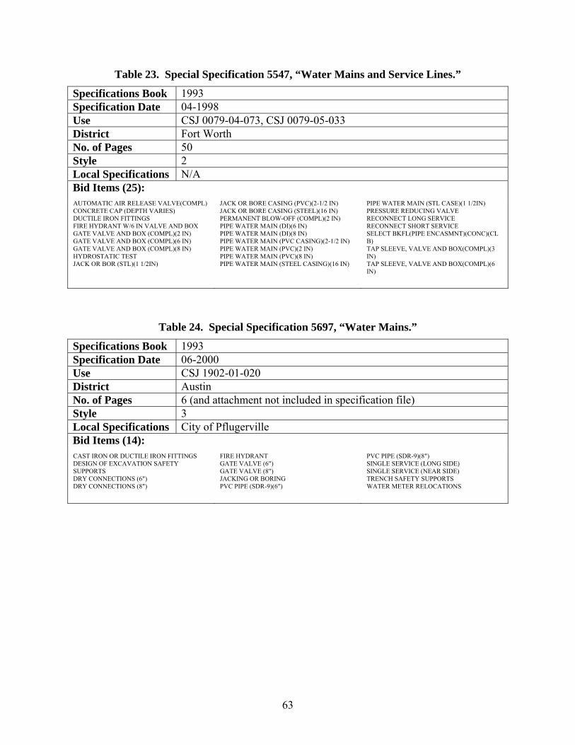
63
Table 23. Special Specification 5547, “Water Mains and Service Lines.”
Specifications Book 1993 Specification Date 04-1998 Use CSJ 0079-04-073, CSJ 0079-05-033 District Fort Worth No. of Pages 50 Style 2 Local Specifications N/A Bid Items (25): AUTOMATIC AIR RELEASE VALVE(COMPL) CONCRETE CAP (DEPTH VARIES) DUCTILE IRON FITTINGS FIRE HYDRANT W/6 IN VALVE AND BOX GATE VALVE AND BOX (COMPL)(2 IN) GATE VALVE AND BOX (COMPL)(6 IN) GATE VALVE AND BOX (COMPL)(8 IN) HYDROSTATIC TEST JACK OR BOR (STL)(1 1/2IN)
JACK OR BORE CASING (PVC)(2-1/2 IN) JACK OR BORE CASING (STEEL)(16 IN) PERMANENT BLOW-OFF (COMPL)(2 IN) PIPE WATER MAIN (DI)(6 IN) PIPE WATER MAIN (DI)(8 IN) PIPE WATER MAIN (PVC CASING)(2-1/2 IN) PIPE WATER MAIN (PVC)(2 IN) PIPE WATER MAIN (PVC)(8 IN) PIPE WATER MAIN (STEEL CASING)(16 IN)
PIPE WATER MAIN (STL CASE)(1 1/2IN) PRESSURE REDUCING VALVE RECONNECT LONG SERVICE RECONNECT SHORT SERVICE SELECT BKFL(PIPE ENCASMNT)(CONC)(CL B) TAP SLEEVE, VALVE AND BOX(COMPL)(3 IN) TAP SLEEVE, VALVE AND BOX(COMPL)(6 IN)
Table 24. Special Specification 5697, “Water Mains.”
Specifications Book 1993 Specification Date 06-2000 Use CSJ 1902-01-020 District Austin No. of Pages 6 (and attachment not included in specification file) Style 3 Local Specifications City of Pflugerville Bid Items (14): CAST IRON OR DUCTILE IRON FITTINGS DESIGN OF EXCAVATION SAFETY SUPPORTS DRY CONNECTIONS (6") DRY CONNECTIONS (8")
FIRE HYDRANT GATE VALVE (6") GATE VALVE (8") JACKING OR BORING PVC PIPE (SDR-9)(6")
PVC PIPE (SDR-9)(8") SINGLE SERVICE (LONG SIDE) SINGLE SERVICE (NEAR SIDE) TRENCH SAFETY SUPPORTS WATER METER RELOCATIONS

64
Table 25. Special Specification 5737, “Water Mains and Sanitary Sewers.”
Specifications Book 1993 Specification Date 10-2000 Use CSJ 2121-02-090, etc. District El Paso No. of Pages 21 Style 4 Local Specifications N/A Bid Items (14): ABANDON MANHOLE ADDITIONAL FITTINGS CASING (STEEL)(ASTM A36)(6") GATE VALVES (6") MANHOLE (EXTRA DEPTH)(STD)(48" DIA)
MANHOLE (STD)(48" DIA)(6 FT DEPTH) SAN SEWER (DUCTILE IRON PIPE)(12") SAN SEWER (DUCTILE IRON PIPE)(15") SAN SEWER SERVICE (REPL & RECON)(4") WATER MAIN (PVC PIPE)(C900/CL 150)(2")
WATER MAIN (PVC PIPE)(C900/CL 150)(6") WATER SERVICE (RPL & RECON)(1") WATER SERVICE (RPL & RECON)(1-1/2") WATER SERVICE (RPL & RECON)(3/4")
Table 26. Special Specification 5757, “Sanitary Sewers.”
Specifications Book 1993 Specification Date 01-2001 Use CSJ 0216-03-023 District San Antonio No. of Pages 16 Style 4 Local Specifications N/A Bid Items (13): SAN SEW (10 IN) SAN SEW (21 IN) SAN SEW (6 IN)(LATERAL SERV CONN) SAN SEW (ABANDON CLEAN OUT) SAN SEW (ABANDON MANHOLE)
SAN SEW (ABANDON PIPE)(12 IN) SAN SEW (ABANDON PIPE)(6 IN) SAN SEW (ABANDON PIPE)(8 IN) SAN SEW (ADJUST MANHOLE) SAN SEW (CUT & RESTORE PVMNT)TY II
SAN SEW (MANH)(RING & COVER)WTR TIGHT SAN SEW (TRENCH EXCAVATION PROTECTION) SAN SEWER (8 IN)

65
Table 27. Special Specification 5791, “Water Mains & Sanitary Sewer.”
Specifications Book 1993 Specification Date 05-2001 Use CSJ 0924-06-178, CSJ 2121-03-114 District El Paso No. of Pages 118 Style 4 Local Specifications N/A Bid Items (30): ABANDON MANHOLE AC PIPE REMOVAL AND DISPOSAL (12 IN) ADJUST EXIST BUTTERFLY VALVE (20 IN) ADJUST EXIST WATER VALVE (8 IN) ADJUST EXISTING MANHOLE AIR RELEASE VLV & MNHL (REM & SALV) 2IN AIR RELEASE VLV & MNHL ASSEMBLY (2 IN) CASING (STEEL)(48 IN) CEMENT STABILIZED BACKFILL FIRE HYDRANT (NEW)
FIRE HYDRANT (REMV & SALV EXISTING) FIRE LINE (REL&RECON W/BKFL ASSEM)8 IN FIRELINE (RECON ONLY)(6 IN) GATE VALVES (12IN) MANH (STAND)(48 IN)(EXTRA DPTH OVR 6FT) MNHL (TY B)(EX DEPTH OVER 6 FT)(72 ID) PAVEMENT CUT & RESTORE PVC PIPE (C900/CL 150)(8 IN) PVC PIPE (C900/CL 150)(PVC)(12 IN) PVC PIPE (SDR 35)(8 IN)
REMOV AND DISPOSAL OF CONC SLAB 6IN-2FT STANDARD MANHOLE (48 IN)(6 FT DEPTH) STEEL WATER PIPE (30 IN) TAPPING SLEEVE & VALVE (12IN X 6IN) TAPPING SLEEVE & VALVE (8IN X 6IN) TAPPING SLEEVE & VALVE (8IN X 8IN) TRENCH SAFETY SYSTEM WATER SERV (REL&RECON W/BKFL ASSEM) 2IN WATER SERVICE (3/4 IN)(RELOC & RECON) WATER SERVICE (3IN)(RECON ONLY)
Table 28. Special Specification 5834, “Water Mains and Sanitary Sewers.”
Specifications Book 1993 Specification Date 09-2001 Use CSJ 0924-06-171 District El Paso No. of Pages 90 Style 4 Local Specifications N/A Bid Items (25): ABANDON MANHOLE ADJUST EXISTING MANHOLE ADJUST EXISTING VALVE DI PIPE (C150/A 21.50)(TY 1)(8 IN) FIRE HYDRANT (NEW) FIRE HYDRANT (REMOVE & SALVAGE EXIST) GATE VALVES (6 IN) GATE VALVES (8 IN) PVC WATER PIPE (C900)(12 IN)
PVC WATER PIPE (C900/CL 150)(12 IN) PVC WATER PIPE (C900/CL 150)(6 IN) PVC WATER PIPE (C900/CL 150)(8 IN) PVC WATER PIPE (SDR 35)(8 IN) SERV (REPL & RECNT) SWR (COND 1)(4 IN) SERV (REPL & RECNT) SWR (COND 2)(4 IN) SERV (REPL & RECNT) SWR (COND 2)(8 IN) SERV (REPL & RECNT) SWR (COND 3)(4 IN) SERV (REPL & RECNT) SWR (COND 4)(4 IN) STAND M.H.(EX DEPTH/OVER 6)(TY A)(48IN)
STAND MANHOLE (TY A)(6' DEPTH)(48 IN) TAPPING SLEEVE & VALVE (12 IN X 6 IN) TAPPING SLEEVE & VALVE (8 IN X 6 IN) WATER METER(RELOCATE & RECONNECT)(1 IN) WATER METER(RELOCATE & RECONNECT)(1.5") WATER METER(RELOCATE & RECONNECT)(3/4")
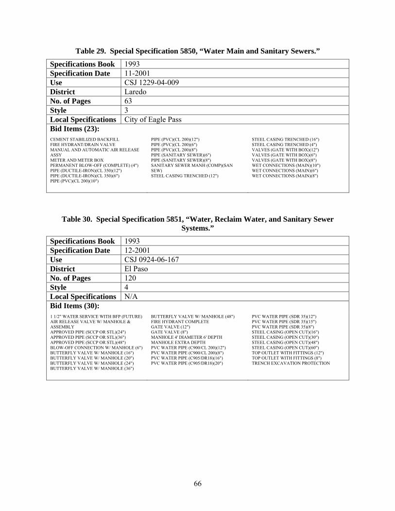
66
Table 29. Special Specification 5850, “Water Main and Sanitary Sewers.”
Specifications Book 1993 Specification Date 11-2001 Use CSJ 1229-04-009 District Laredo No. of Pages 63 Style 3 Local Specifications City of Eagle Pass Bid Items (23): CEMENT STABILIZED BACKFILL FIRE HYDRANT/DRAIN VALVE MANUAL AND AUTOMATIC AIR RELEASE ASSY METER AND METER BOX PERMANENT BLOW-OFF (COMPLETE) (4") PIPE (DUCTILE-IRON)(CL 350)(12") PIPE (DUCTILE-IRON)(CL 350)(6") PIPE (PVC)(CL 200)(10")
PIPE (PVC)(CL 200)(12") PIPE (PVC)(CL 200)(6") PIPE (PVC)(CL 200)(8") PIPE (SANITARY SEWER)(6") PIPE (SANITARY SEWER)(8") SANITARY SEWER MANH (COMP)(SAN SEW) STEEL CASING TRENCHED (12")
STEEL CASING TRENCHED (16") STEEL CASING TRENCHED (4") VALVES (GATE WITH BOX)(12") VALVES (GATE WITH BOX)(6") VALVES (GATE WITH BOX)(8") WET CONNECTIONS (MAIN)(10") WET CONNECTIONS (MAIN)(6") WET CONNECTIONS (MAIN)(8")
Table 30. Special Specification 5851, “Water, Reclaim Water, and Sanitary Sewer Systems.”
Specifications Book 1993 Specification Date 12-2001 Use CSJ 0924-06-167 District El Paso No. of Pages 120 Style 4 Local Specifications N/A Bid Items (30): 1 1/2" WATER SERVICE WITH BFP (FUTURE) AIR RELEASE VALVE W/ MANHOLE & ASSEMBLY APPROVED PIPE (SCCP OR STL)(24") APPROVED PIPE (SCCP OR STL)(36") APPROVED PIPE (SCCP OR STL)(48") BLOW-OFF CONNECTION W/ MANHOLE (6") BUTTERFLY VALVE W/ MANHOLE (16") BUTTERFLY VALVE W/ MANHOLE (20") BUTTERFLY VALVE W/ MANHOLE (24") BUTTERFLY VALVE W/ MANHOLE (36")
BUTTERFLY VALVE W/ MANHOLE (48") FIRE HYDRANT COMPLETE GATE VALVE (12") GATE VALVE (8") MANHOLE 4' DIAMETER 6' DEPTH MANHOLE EXTRA DEPTH PVC WATER PIPE (C900/CL 200)(12") PVC WATER PIPE (C900/CL 200)(8") PVC WATER PIPE (C905/DR18)(16") PVC WATER PIPE (C905/DR18)(20")
PVC WATER PIPE (SDR 35)(12") PVC WATER PIPE (SDR 35)(15") PVC WATER PIPE (SDR 35)(8") STEEL CASING (OPEN CUT)(16") STEEL CASING (OPEN CUT)(30") STEEL CASING (OPEN CUT)(48") STEEL CASING (OPEN CUT)(60") TOP OUTLET WITH FITTINGS (12") TOP OUTLET WITH FITTINGS (8") TRENCH EXCAVATION PROTECTION
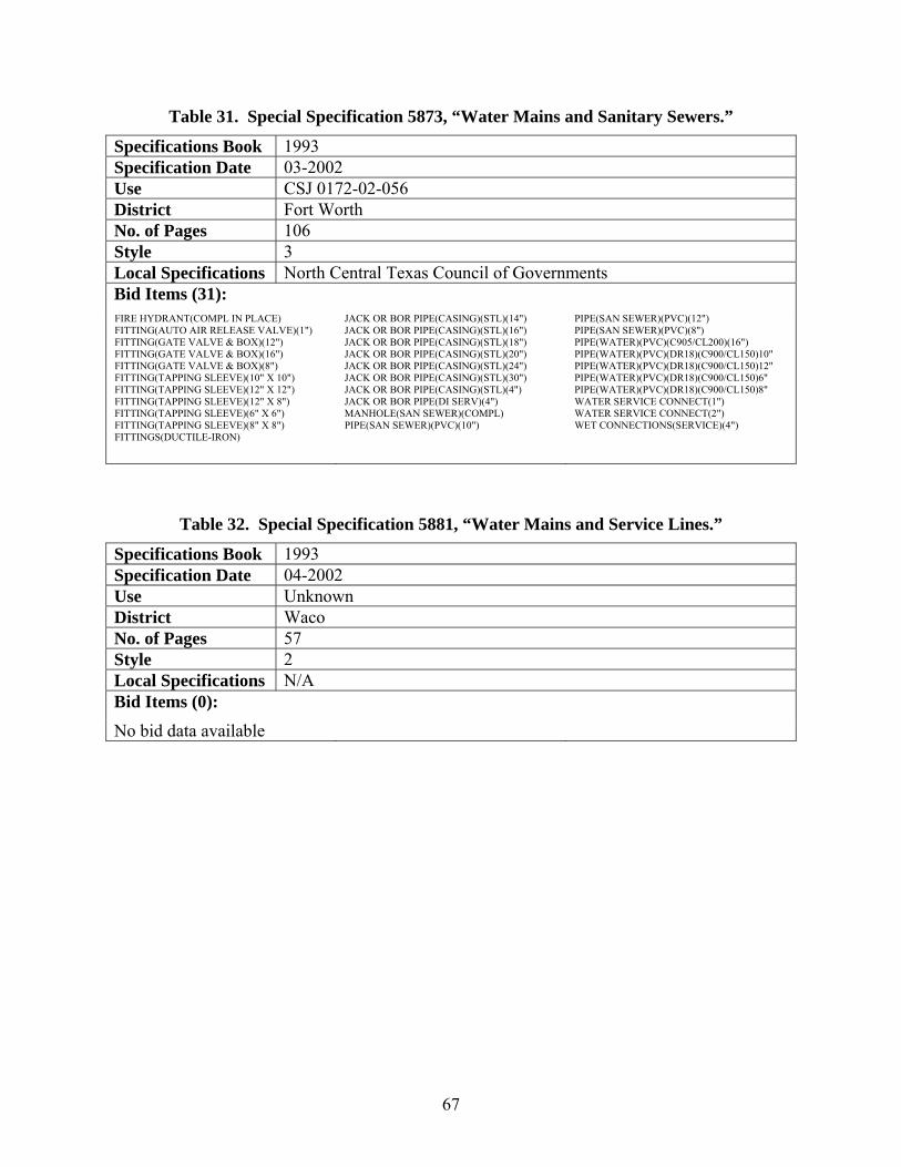
67
Table 31. Special Specification 5873, “Water Mains and Sanitary Sewers.”
Specifications Book 1993 Specification Date 03-2002 Use CSJ 0172-02-056 District Fort Worth No. of Pages 106 Style 3 Local Specifications North Central Texas Council of Governments Bid Items (31): FIRE HYDRANT(COMPL IN PLACE) FITTING(AUTO AIR RELEASE VALVE)(1") FITTING(GATE VALVE & BOX)(12") FITTING(GATE VALVE & BOX)(16") FITTING(GATE VALVE & BOX)(8") FITTING(TAPPING SLEEVE)(10" X 10") FITTING(TAPPING SLEEVE)(12" X 12") FITTING(TAPPING SLEEVE)(12" X 8") FITTING(TAPPING SLEEVE)(6" X 6") FITTING(TAPPING SLEEVE)(8" X 8") FITTINGS(DUCTILE-IRON)
JACK OR BOR PIPE(CASING)(STL)(14") JACK OR BOR PIPE(CASING)(STL)(16") JACK OR BOR PIPE(CASING)(STL)(18") JACK OR BOR PIPE(CASING)(STL)(20") JACK OR BOR PIPE(CASING)(STL)(24") JACK OR BOR PIPE(CASING)(STL)(30") JACK OR BOR PIPE(CASING)(STL)(4") JACK OR BOR PIPE(DI SERV)(4") MANHOLE(SAN SEWER)(COMPL) PIPE(SAN SEWER)(PVC)(10")
PIPE(SAN SEWER)(PVC)(12") PIPE(SAN SEWER)(PVC)(8") PIPE(WATER)(PVC)(C905/CL200)(16") PIPE(WATER)(PVC)(DR18)(C900/CL150)10" PIPE(WATER)(PVC)(DR18)(C900/CL150)12" PIPE(WATER)(PVC)(DR18)(C900/CL150)6" PIPE(WATER)(PVC)(DR18)(C900/CL150)8" WATER SERVICE CONNECT(1") WATER SERVICE CONNECT(2") WET CONNECTIONS(SERVICE)(4")
Table 32. Special Specification 5881, “Water Mains and Service Lines.”
Specifications Book 1993 Specification Date 04-2002 Use Unknown District Waco No. of Pages 57 Style 2 Local Specifications N/A Bid Items (0):
No bid data available

68
Table 33. Special Specification 5885, “Water and Sanitary Sewer Systems.”
Specifications Book 1993 Specification Date 05-2002 Use CSJ 0001-03-033 District El Paso No. of Pages 121 Style 4 Local Specifications N/A Bid Items (27): ADDITIONAL FITTINGS ADJUST EXISTING MANHOLE DUCTILE IRON PIPE 12 IN DUCTILE IRON PIPE 18 IN DUCTILE IRON PIPE 6 IN DUCTILE IRON PIPE 8 IN FIRE HYDRANT (REMOV & SALV EXISTING) GATE VALVE 12 IN GATE VALVE 6 IN
GATE VALVE 8 IN NEW FIRE HYDRANT PVC SDR-35 PIPE 12 IN PVC SDR-35 PIPE 8 IN REMOVAL & DISPOSAL OF AC PIPE STD MANHOLE 48"DIA 6'DEPTH STD MHOLE 48" DIA EXTR DPTH OVER 6' STEEL CASING (ASTM A36) 12 IN STEEL CASING (ASTM A36) 20 IN
STEEL CASING (ASTM A36) 6 IN STEEL CASING BORED (ASTM A36) 12 IN STEEL CASING BORED (ASTM A36) 20 IN STEEL CASING BORED (ASTM A36) 6 IN STEEL CASING SPLT (ASTM A53,GRB) 48 IN TAPPING VALVE 12 IN WATER SERVICE RPL & RECON 1 IN WATER SERVICE RPL & RECON 2 IN WATER SERVICE RPL & RECON 3/4 IN
Table 34. Special Specification 5915, “Water Mains and Sanitary Sewers.”
Specifications Book 1993 Specification Date 09-2002 Use CSJ 0151-09-029 District Austin No. of Pages 169 Style 3 Local Specifications City of Austin Bid Items (55): ADJ STRUCT (WATER VALVE BOX) ADJ WATER METER (5/8 IN TO 2 IN) ADJ WATER METER(>=3")(W/MTR VAULT)CMPL ADJUST STRUCTURE (MANHOLE 4 FT MAJOR) ADJUST STRUCTURE (MANHOLE 4 FT MINOR) CONCRETE ENCASEMENT (FOR 12 IN PIPE) CONCRETE ENCASEMENT (FOR 18 IN PIPE) CONCRETE ENCASEMENT (FOR 24 IN PIPE) CONCRETE ENCASEMENT (FOR 8 IN PIPE) CST IRON OR DCTL IRON FTTNG (DUCTILE) ENCASEMENT PIPE (STL)(16 IN) ENCASEMENT PIPE (STL)(16 IN)(BORE) ENCASEMENT PIPE (STL)(24 IN) ENCASEMENT PIPE (STL)(24 IN)(BORE) ENCASEMENT PIPE (STL)(26 IN) ENCASEMENT PIPE (STL)(26 IN)(BORE) ENCASEMENT PIPE (STL)(28 IN) ENCASEMENT PIPE (STL)(28 IN)(BORE) FIRE HYDRNT/DRAIN VALVE ASSEM (COMPL)
LAT SRV(INST/RECN)1.5"COP MIN(1.5"DIA) MANH (4')(TY COA)(COMPL)ALL DPTH MANH (6')(TY COA)BOLT LID(COMPL) MANH(4')(TY COA)BOLT LID(COMPL)ALL DPT MANH(5')(TY COA)(COMPL)ALL DPTH MANH(5')(TY COA)BOLT LID(COMPL) 3'DEEP MANH(5')(TY COA)BOLT LID(COMPL)12'DEEP MANH(5')(TY COA)BOLT LID(COMPL)23'DEEP MANH(5')(TY COA)BOLT LID(COMPL)32'DEEP MANH(5')(TY COA)BOLT LID(COMPL)37'DEEP MANH(5')(TY COA)BOLT LID(COMPL)47'DEEP MANH(5')(TY COA)BOLT LID(COMPL)ALL DPT MANHOLE REHABILITATION MICROTUNNEL (CCRP)(24 IN)(COMPL) MICROTUNNEL (STL)(20 IN)(COMPL)
MICROTUNNEL ACCESS SHFT AND RETEN SYS PIPE (DI)(CL 350)(12 IN)(ALL DEPTHS) PIPE (DI)(CL 350)(16 IN)(ALL DEPTHS) PIPE (DI)(CL 350)(4 IN)(ALL DEPTHS) PIPE (DI)(CL 350)(6 IN)(ALL DEPTHS) PIPE (DI)(CL 350)(8 IN)(ALL DEPTHS) PIPE(CCRP)(24 IN) PIPE(PVC)(SDR 26)(12 IN)(ALL DEPTHS) PIPE(PVC)(SDR 26)(15 IN)(ALL DEPTHS) PIPE(PVC)(SDR 26)(18 IN)(ALL DEPTHS) PIPE(PVC)(SDR 26)(24 IN)(ALL DEPTHS) PIPE(PVC)(SDR 26)(6 IN)(ALL DEPTHS) PIPE(PVC)(SDR 26)(8 IN)(ALL DEPTHS) TRENCH SAFETY SYSTEMS VALVE (GATE)(12 IN)(COMPL) VALVE (GATE)(6 IN)(COMPL) VALVE (GATE)(8 IN)(COMPL) VALVE (RES SEAT)(GATE)(16")IRON(COMPL) WET CONNECTION (12 IN)(COMPL) WET CONNECTION (6 IN)(COMPL) WET CONNECTION (8 IN)(COMPL)
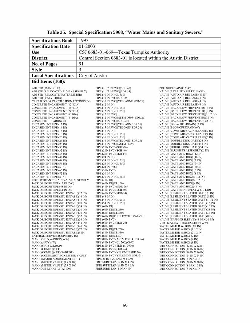
69
Table 35. Special Specification 5968, “Water Mains and Sanitary Sewers.”
Specifications Book 1993 Specification Date 01-2003 Use CSJ 0683-01-069—Texas Turnpike Authority District Control Section 0683-01 is located within the Austin District No. of Pages 91 Style 3 Local Specifications City of Austin Bid Items (168): ADJ STR (MANHOLE) ADJ STR (RELOCATE VALVE ASSEMBLY) ADJ STR (RELOCATE WATER METER) ADJ STR (VALVE BOX) CAST IRON OR DUCTILE IRON FITTINGS(DI) CONCRETE ENCASEMENT (12" DIA) CONCRETE ENCASEMENT (16" DIA) CONCRETE ENCASEMENT (24" DIA) CONCRETE ENCASEMENT (6" DIA) CONCRETE ENCASEMENT (8" DIA) CONCRETE RETARDS (W) ENCASEMENT PIPE (12 IN) ENCASEMENT PIPE (14 IN) ENCASEMENT PIPE (16 IN) ENCASEMENT PIPE (18 IN) ENCASEMENT PIPE (20 IN) ENCASEMENT PIPE (24 IN) ENCASEMENT PIPE (28 IN) ENCASEMENT PIPE (30 IN) ENCASEMENT PIPE (32 IN) ENCASEMENT PIPE (36 IN) ENCASEMENT PIPE (42 IN) ENCASEMENT PIPE (48 IN) ENCASEMENT PIPE (54 IN) ENCASEMENT PIPE (6 IN) ENCASEMENT PIPE (66 IN) ENCASEMENT PIPE (72 IN) ENCASEMENT PIPE (8 IN) FIRE HYDRANT/DRAIN VALVE ASSEMBLY JACK OR BORE PIPE (12 IN PVC) JACK OR BORE PIPE (48 IN DI) JACK OR BORE PIPE (54 IN DI) JACK OR BORE PIPE (STL ENCASE)(12 IN) JACK OR BORE PIPE (STL ENCASE)(16 IN) JACK OR BORE PIPE (STL ENCASE)(18 IN) JACK OR BORE PIPE (STL ENCASE)(20 IN) JACK OR BORE PIPE (STL ENCASE)(24 IN) JACK OR BORE PIPE (STL ENCASE)(30 IN) JACK OR BORE PIPE (STL ENCASE)(30 IN) JACK OR BORE PIPE (STL ENCASE)(32 IN) JACK OR BORE PIPE (STL ENCASE)(36 IN) JACK OR BORE PIPE (STL ENCASE)(42 IN) JACK OR BORE PIPE (STL ENCASE)(48 IN) JACK OR BORE PIPE (STL ENCASE)(72 IN) JACK OR BORE PIPE (STL ENCASE)(8 IN) LATERAL SERVICE (COPPER)(2 IN) MANH (5 FT)(W/DROP)(WW) MANH (5 FT)(WW) MANH (6 FT)(W/DROP) MANH (COMPL)(4 FT) MANH (COMPL)(4 FT)(W/DROP) MANH (COMPL)(JCT BOX METER VAULT) MANH (MAJOR ADJUSTMENT)(4 FT) MANH (METER VAULT) (15' X 10') MANH (METER VAULT) (25' X 10') MANHOLE REHABILITATION
PIPE (1 1/2 IN PVC)(SCH 40) PIPE (1 1/2 IN PVC)(SDR 14) PIPE (10 IN DI)(CL 350) PIPE (10 IN PVC)(SDR-26) PIPE (10 IN PVC)(YELOMINE SDR-21) PIPE (12 IN DI) PIPE (12 IN DI)(CL 250) PIPE (12 IN DI)(CL 350) PIPE (12 IN PVC) PIPE (12 IN PVC)(ASTM D3034 SDR 26) PIPE (12 IN PVC)(SDR -26) PIPE (12 IN PVC)(YELOMIN SDR 26) PIPE (15 IN PVC)(YELOMIN SDR 26) PIPE (16 IN DI) PIPE (16 IN DI)(CL 250) PIPE (16 IN DI)(CL 350) PIPE (16 IN PVC)(YELOMIN SDR 26) PIPE (18 IN PVC)(ASTM F679) PIPE (2 IN PVC) (SDR-26) PIPE (2 IN PVC)(SCH 40) PIPE (2 IN PVC)(SDR 14) PIPE (24 IN DI) PIPE (24 IN DI)(CL 250) PIPE (24 IN DI)(CL 350) PIPE (24 IN PVC) PIPE (3 IN PVC) PIPE (30 IN DI) PIPE (30 IN DI)(CL 350) PIPE (4 IN DI) PIPE (4 IN DI)(CL 150) PIPE (4 IN PVC) (SDR-26) PIPE (4 IN PVC)(SCH 40) PIPE (4 IN PVC)(SDR-14) PIPE (48 IN DI) PIPE (48 IN DI)(CL 250) PIPE (54 IN DI)(CL 250) PIPE (6 IN DI) PIPE (6 IN DI)(CL 250) PIPE (6 IN DI)(CL 350) PIPE (6 IN DI)(FH/BLOWOFF VALVE) PIPE (6 IN PVC) PIPE (6 IN PVC)(SDR-26) PIPE (8 IN DI) PIPE (8 IN DI)(CL 250) PIPE (8 IN DI)(CL 350) PIPE (8 IN DI)(CL 50) PIPE (8 IN PVC)(ASTM D3034 SDR 26) PIPE (8 IN PVC)(CL 200)(C900) PIPE (8 IN PVC)(SDR 18-C900) PIPE (8 IN PVC)(SDR-26) PIPE (8 IN PVC)(YELOMIN SDR 26) PIPE (8 IN PVC)(YELOMINE SDR-21) PIPE(21 IN PVC)(ASTM F679) PRESSURE TAP (12 IN X 4 IN) PRESSURE TAP (16 IN X 4 IN) PRESSURE TAP (6 IN X 4 IN)
PRESSURE TAP (8" X 4") VALVE (2 IN AUTO AIR RELEASE) VALVE (AUTO AIR RELEASE)(10 IN) VALVE (AUTO AIR RELEASE)(3 IN) VALVE (AUTO AIR RELEASE)(4 IN) VALVE (AUTO AIR RELEASE)(6 IN) VALVE (BACKFLOW PREVENTER) (4 IN) VALVE (BACKFLOW PREVENTER) (8 IN) VALVE (BACKFLOW PREVENTER)(1 1/2 IN) VALVE (BACKFLOW PREVENTER)(12 IN) VALVE (BACKFLOW PREVENTOR)(2 IN) VALVE (BLOW OFF/DRAIN) (2 IN) VALVE (BLOWOFF/DRAIN)(6") VALVE (COMB AIR/VAC RELEASE)(2 IN) VALVE (COMB AIR\VAC RELEASE)(4 IN) VALVE (COMB AIR\VAC RELEASE)(6 IN) VALVE (DOUBLE DISK GATE)(24 IN) VALVE (DOUBLE DISK GATE)(48 IN) VALVE (DOUBLE DISK GATE)(54 IN) VALVE (FLUSHING ASSEMBLY)(6 IN) VALVE (GATE AND BOX) (12 IN) VALVE (GATE AND BOX) (16 IN) VALVE (GATE AND BOX) (2 IN) VALVE (GATE AND BOX) (24 IN) VALVE (GATE AND BOX) (30 IN) VALVE (GATE AND BOX) (6 IN) VALVE (GATE AND BOX) (8 IN) VALVE (GATE AND BOX)(1 1/2 IN) VALVE (GATE AND BOX)(2 1/2 IN) VALVE (GATE AND BOX)(4 IN) VALVE (GATE AND BOX)(48 IN) VALVE (GATE)(8 IN)(W/EXT & C-7 LID) VALVE (RESILIENT SEATED GATE) (3 IN) VALVE (RESILIENT SEATED GATE) (6 IN) VALVE (RESILIENT SEATED GATE)(1 1/2 IN) VALVE (RESILIENT SEATED GATE)(12 IN) VALVE (RESILIENT SEATED GATE)(16 IN) VALVE (RESILIENT SEATED GATE)(24 IN) VALVE (RESILIENT SEATED GATE)(36 IN) VALVE (RESILIENT SEATED GATE)(8 IN) VALVE (TAPPING SLEEVE)(48 IN X 36 IN) VERTICAL EXT (MANHOLE)(4')(WW) WATER METER W/ BOX (3/4 IN) WATER METER W/BOX (1 1/2 IN) WATER METER W/BOX (2 1/2 IN) WATER METER W/BOX (2 IN) WATER METER W/BOX (4 IN) WATER METER W/BOX (8 IN) WET CONNECTION (12 IN X 12 IN) WET CONNECTION (12 IN X 16 IN) WET CONNECTION (16 IN X 16 IN) WET CONNECTION (24 IN X 24 IN) WET CONNECTION (3 IN X 3 IN) WET CONNECTION (30 IN X 30 IN) WET CONNECTION (8 IN X 16 IN) WET CONNECTION (8 IN X 8 IN)
70
An analysis of common trends and differences among special specifications yields the following observations:
• Some special specifications incorporate legal and administrative requirements such as contractor qualifications, definitions of ownership, and warranty requirements—which are normally addressed by standard items 001 – 009. This is typically the case of special specifications that include partial or complete copies of construction specifications from local jurisdictions. Some of those “general provisions” are quite generic, making monitoring and inspection difficult. For example, Special Specification 5528, “Water Mains and Sanitary Sewers,” includes the following text under “Safety”: “The Contractor shall at all times exercise reasonable precautions for the safety of workers and the public, and shall comply with applicable provisions of all Federal and State safety laws and regulations. The safety precautions taken and their adequacy shall be the sole responsibility of the Contractor.” Special Specification 5697, “Water Mains,” also includes a general safety statement, but also requires a trench safety plan to be prepared by a Texas-licensed professional engineer.
• Some special specifications include amendments to standard specifications, instead of relying on special provisions to amend those standard specifications. This is the case of Special Specification 5791, “Water Mains & Sanitary Sewer,” which amends standard Item 400, “Excavation and Backfill for Structures.” The amendments include voiding, replacing, and supplementing text. Interestingly, the corresponding bid items are 5791-series items instead of 0400-series items: Specification Bid Item Code Description 5791 57910511 CEMENT STABILIZED BACKFILL 5791 57910512 PAVEMENT CUT AND RESTORE In other cases, the construction method specifies activities according to the standard specifications, but the specification includes non-standard specification payment items. This is the case of earth work items included in Special Specification 5177, “Sanitary Sewers”: Specification Bid Item Code Description 5177 51770503 SAN SEWER (CUT AND RESTORE PVMT) 5177 51770522 SAN SEWER (FLOWABLE BACKFILL) 5177 51770501 SAN SEWER (TRENCH EXCAV PROTECTION)
• Many special specifications borrow heavily from previous versions. This is usually the
case of specifications developed for projects within the same district, although there are several cases of districts developing specifications using text borrowed from other districts. In other cases, there are substantial modifications to the special specifications, even within the same district. However, the process of updating the specifications sometimes results in inconsistencies and poor sentence construction. For example, Special Specification 5389, “Sanitary Sewers,” includes the following text under Measurement:

71
“Longitudinal measurement of sanitary sewers will be made along the centerline of the sewer by the linear foot of the various sizes and types of sewers in place, in accordance with these specifications, complete and accepted by the Engineer.” Later versions (for example Special Specification 5834, “Water Mains and Sanitary Sewers”) contain the following language: “The linear foot of the various sizes will make longitudinal measurement of sanitary sewers along the centerline of the sewer and types of sewers in place, in accordance with these specifications, complete and accepted by the Engineer.” In other cases, text is miscopied. For example, page 23 of Special Specification 5791, “Water Mains & Sanitary Sewer,” includes the following text concerning payment under Measurement (but then refers to the Measurement section): (7) “Cement Stabilized Backfill”, measured as provided under “Measurement”, will be paid for at the unit bid price bid for “Cement Stabilized Backfill”. (8) “Pavement Cut and Restore”, measured as provided under “Measurement”, will be paid for at the unit bid price bid for “Pavement Cut and Restore”.
• Pipe furnishing and installation are major cost components, with the following normally
considered as subsidiary items: excavation (not consistently), conventional backfill (flowable backfill is usually paid separately), fittings (valves are usually paid separately), old pipe removal, old pipe grouting, and testing. Because of wide ranges in pipe size and depth, excavation can play a significant role on pipe furnishing and installation unit costs, making the comparison from job to job difficult. Similar considerations apply in the case of backfill, which may vary from conventional (which is normally included in the price of pipe installation) to flowable, which is paid separately. Trench protection is normally paid as a separate item, but directly impacts the excavation phase of the installation.
• Districts label specifications in many different ways (see Table 8, which lists the various special specification titles the researchers found). Unfortunately, bid item names and measurement units also vary widely, which makes unit cost comparisons across projects difficult. For example, in the case of 8-inch ductile iron pipe, the following are some of the bid items found:
Specification Bid Item Code Description 3743 37430521 PIPE (8") DI CL 350 (W) 5664 56640502 SAN SEWER (8 IN)(DI) 5830 58300501 SAN SEWER (DUCTILE-IRON OR PVC)(8 IN) 5834 58340506 DI PIPE (C150/A 21.50)(TY 1)(8 IN) 5879 58790509 PIPE (8")(DI)(CL 350)(ALL DEPTHS) 5885 58850504 DUCTILE IRON PIPE 8 IN
• In general, the special specifications reviewed were one-time use specifications. This
might explain the inclusion of names of individuals and corresponding contact information. This is the case of Special Specification 5791, “Water Mains & Sanitary

72
Sewer,” which includes the name and contact information of an Austin Energy official for the coordination of pole bracing activities.
• Using a specification style different from the standard specification style can make the process of understanding and following the specification text quite challenging. This problem is particularly evident in the case of Style 3 special specifications (Figure 15), which typically include an attachment with specifications from local jurisdictions, because of the difficulty in mapping the relationship between technical requirements, measurement units, and payment conditions. Style 4 special specifications, which rely on different sections each one including different construction items and corresponding specification articles, are also difficult to follow and understand. This problem is particularly evident in situations where the distinction between construction items is apparently clear. For example, Special Specification 5791, “Water Mains & Sanitary Sewer,” includes separate sections for “Piping Systems” (does not include measurement and payment), “Water Mains and Sanitary Sewers,” “Sanitary Sewer,” “Sanitary Sewers,” “Plastic Pipe,” and “Steel Transmission Pipelines.” There is considerable content overlap between sections, which raises the question of whether keeping separate sections to cover similar items is a sound strategy.
• Most Style 1 and Style 2 special specifications tend to be consistent in terms of the relationship between specification content (text, measurement units, and payment conditions) and bid items. In contrast, many Style 3 and Style 4 specifications include content that is frequently not represented in the corresponding list of bid items. In particular, the list of payment items actually included in the bidding documents is normally just a small subset of the total list of bid items that could potentially result from the special specifications. The actual list of bid items used normally pertains to the utility installation itself (pipe, valves, hydrants, meter boxes, casing, laterals, and so on), leaving out items such as mobilization, traffic control, concrete and pavement removal, all of which are already included and paid for separately in the highway construction contract. Interestingly, a few special specifications also include some of these items in the unit utility installation price. For example, Special Specification 3743, “Water and Wastewater Mains,” includes traffic control in the unit price of pipe, even though the highway contract already includes traffic control items.
• Some specifications include measurement and payment conditions for abandoning pipes and manholes. For example, Special Specification 5968, “Water Mains and Sanitary Sewers,” includes the following text under Measurement: “Abandon Pipe”, when included in the plans as a pay item will be measured by the linear foot, along the centerline of existing pipe, of the size and type specified on the plans. Only those pipes designated on the plans to be abandoned and directed by the Engineer shall be measured for payment under this Item. The same specification includes the following text under Payment: Payment for abandoning pipe in place will be made at the unit price bid for "Abandon Pipe" of the size and type specified. This price shall be full compensation for furnishing all materials, tools, labor, equipment and incidentals necessary to complete the work as specified on the plans.

73
However, there is no description in the specification as to what abandoning a pipe entails.
• There is considerable variability in item payment, particularly in the case of excavation, backfill, casing, salvaging and removing structures, pavement cut and restore, and fittings. Most specifications list excavation and backfill as subsidiary items to pipe installation. However, some specifications provide direct payment for extra excavation and select backfill. Likewise, most specifications list fittings as subsidiary items to pipe installation. However, some specifications, e.g., Special Specification 5968, “Water Mains and Sanitary Sewers,” provide payment (by the ton) for fittings sizes 24 inches and smaller. The same specification considers fittings larger than 24 inches subsidiary to the pipe. In the case of backfill, specifications usually consider regular backfill a subsidiary item, but treat cement stabilized backfill and flowable backfill separate payable items. In some cases, e.g., Special Specification 3692, “Water Mains and Sanitary Sewers,” the specification includes a measurement and payment article for backfill but does not state whether backfill is a pay item or a subsidiary item. Some other specifications, e.g., Special Specification 3724, “Water Mains and Sanitary Sewers,” treat backfill as a pay item, but only if the contract document lists backfill as a separate bid item. Since the item did not appear in the final bid item list, one would have to assume that backfill was treated as a subsidiary item.
• There are several examples of inconsistencies in payment conditions. For example, Special Specification 5547, “Water Mains and Service Lines,” establishes that payment for jacking and boring casing should be at the unit price of the water main: Payment for "Pipe Water Main (DI)", "Pipe Water Main (PVC)", "Pipe Water Main (PVC Casing)", and "Pipe Water Main (Steel Casing)" will be paid at the unit price bid per linear foot of pipe of the various sizes installed by the open cut method. This payment shall also include selected bedding, excavation, backfill materials, and polyethylene sleeve. Payment for “Jacking or Boring Casing (PVC)” and "Jacking or Boring Casing (Steel)" will be made at the unit price bid per linear foot of the size and type of water main or casing jacked, bored or tunneled. This payment shall include the furnishing of the water pipe and/or casing, coating, wrapping, timber cleats, stainless steel strapping, grouting, selected embedment material, anti-corrosion embedment when specified, backfill, surface restoration, hauling and disposal of surplus materials. Where the plans call for the water main to be placed in a jacked, bored or tunneled casing, payment will be made for the water main at the unit price bid per linear foot of "Pipe Water Main" as specified above. Similarly, Special Specification 5737, “Water Mains and Sanitary Sewers,” first indicates that valves should be considered subsidiary to the cost of installation of the pipe, but later implies that gate valves are to be paid separately: Water Mains, measured as provided under "Measurement", will be paid for at the unit price bid for "Water Mains", of the particular type and size specified. This price shall include all materials, labor, tools, equipment and incidentals necessary to complete the work. Thrust blocks, fittings, couplings, valves and valve boxes will not be paid for directly, but shall be considered subsidiary to this Item. Gate Valves, measured as provided under "Measurement", will be paid for at the unit price bid for "Gate

74
Valves" of the size specified. Likewise, Special Specification 5968, “Water Mains and Sanitary Sewers,” includes the following text under Measurement: Abandonment of manholes, when called for in drawings, will not be measured, but will be considered subsidiary to “Manholes.” However, the specification does not describe what abandoning a manhole entails. Special Specification 5968 also considers all excavation and backfill to be subsidiary to the installation of pipe. However, one of the bid items in the same specification, cement stabilized backfill, provides full compensation for excavation, which might suggest that excavation may be paid for twice. Interestingly, the list of bid items did not make any reference to backfill, suggesting the unit price for pipe did indeed include excavation and backfill.
OTHER SPECIFICATION PRACTICES IN TEXAS
As mentioned previously, TxDOT frequently relies on construction specifications from local jurisdictions to prepare special specifications for utility relocations. For completeness, the researchers conducted a brief review of utility specification practices across Texas to determine similarities and differences among them and to assess potential characteristics that could be beneficial for implementation at TxDOT. The analysis focused on structure and content characteristics. During the review phase, the researchers examined examples from several jurisdictions, although focused on specifications from the City of Austin, City of Houston, San Antonio Water System (SAWS), and the North Central Texas Council of Governments (NCTCOG) ( 51, 52, 53, 54). In general, construction specifications from these jurisdictions tend to be more detailed and exceed the requirements of those included in the TxDOT standard specifications ( 44). Although pay items as well as material and construction requirements are similar among jurisdictions, specification structure and style tend to be different, which makes the comparison more challenging. Most jurisdictions list material requirements and construction requirements separately. In general, material requirement sections list material requirements for different types of pipes and applications (typically water and sanitary sewer applications), while the construction requirement sections describe pipe installation procedures (typically separate sections for different types of pipe and application). Usually the construction requirement sections include the list of bid items, as well as measurement and payment requirements. When examined on a content basis, material and construction requirements for different jurisdictions tend to be similar. Most specifications tend to include references to the same industry standards, in particular those from ASTM International and the American Water Works Association (AWWA). For example, all jurisdictions use AWWA C900, “Polyvinyl Chloride

75
(PVC) Pressure Pipe, and Fabricated Fittings, 4 In.–12 In.” and AWWA C905, “Polyvinyl Chloride (PVC) Pressure Pipe and Fabricated Fittings, 14 In.–48 In.” to specify PVC water pipe. Despite the similarities, there are some differences, mainly dealing with additional local requirements. For example, in the case of ductile iron pipe, the NCTCOG specification relies almost exclusively on AWWA and ASTM standards, providing very little additional detail on specific requirements. In contrast, the City of Houston references standards from AWWA, ASTM, and AASHTO, but also lists extensive requirements including working pressure, minimum and maximum surge pressures, minimum tensile stress due to surge, and specific bedding characteristics. Some jurisdictions include lists of approved manufacturers, while other jurisdictions may list generic performance requirements pipe manufacturers must meet. More significant content differences appear to reside in emerging technology areas. For example, NCTCOG and the City of Austin’s trenchless specifications contain less detail than the corresponding specification from the City of Houston. Both NCTCOG and the City of Austin have one specification that covers all forms of trenchless installations and reference few industry standards. In contrast, City of Houston specifications divide trenchless installations into three sections: microtunneling and pipe-jacked tunnels, augering pipe and conduit, and pipe and casing augering for sewers, which provide greater detail than the NCTCOG or Austin specifications.
PROPOSED SPECIFICATION FRAMEWORK
TxDOT districts, as well as local jurisdictions, have different ideas concerning the development of water and sanitary sewer specifications. Despite the differences, however, there are many content similarities that provide a strong justification for the development of standardized water main and sanitary sewer specifications at TxDOT. Many different approaches might be possible for standardizing water main and sanitary sewer specifications. One such approach involves developing a specification framework similar to that which TxDOT uses for drainage/storm sewer structures. Advantages of following this approach include: (a) a long history at TxDOT developing storm sewer specifications and associated unit cost structures, (b) the close relationship between those specifications and other specifications included in a typical highway construction contract, and (c) the increased likelihood that TxDOT would adopt a similar structure for water mains and sanitary sewers if the proposed specification framework is as close to current business processes as possible. Figure 16 and Figure 17 show TxDOT’s current framework for drainage structure specifications. Figure 16 shows the 1993 specification framework, and Figure 17 shows the 2004 specification framework. For convenience, both figures show five groups of specifications: Earth Work, Pipes and Boxes, Appurtenances, Other, and a fifth group (left-most column) that includes standard specifications such as mobilization and traffic control, which highway construction contracts typically include but, at the same time, are relevant to the utility relocation process. There are some differences between the 1993 and 2004 standard specifications. Other than the change in the number of articles mentioned previously and the change in format ( 50), some changes are relatively minor (e.g., specification name change), but other changes are more substantial. For example, Item 402, “Trench Excavation Protection,” now applies exclusively to pipes, whereas Item 403, “Temporary Special Shoring,” is not supposed to be used for pipes ( 55). Item 401,

76
“Flowable Backfill,” is new in 2004. In general, individual specifications address relatively homogeneous construction topics. The two noticeable exceptions are Item 400 (which includes excavation, backfill—other than flowable backfill—for structures, and cutting and restoring pavement) and Item 465 (which includes manholes and inlets).
Earth Work
402
Trench Excavation Protection
403
Temporary Special Shoring
General
500
Mobilization
502 508 510 512
Traffic Control
464
Reinforced Concrete Pipe
Specification Name
Specification Number
100
Preparing Right of Way
Pipes and Boxes Appurtenances
460
Corrugated Metal Pipe
464
Reinforced Concrete Pipe
476
Jacking, Boring, or Tunneling Pipe
462
Concrete Box Culverts and
Sewers
465
Manholes and Inlets
466
Headwalls and Wingwalls
467
Safety End Treatment
471
Frames, Grates, Rings, and
Covers
472
Removing and Re-Laying Culvert and Storm Sewer
Pipe
473
Laying Culvert and Storm Sewer
Pipe
474
Slotted Drain
480
Cleaning Existing Culverts
481
PVC Pipe for Bridge Drains
556
Pipe Underdrains
Other
497
Disposal of Salvageable
Material
104 105
Removing Concrete, Asphalt
Pavement
529 530 531 536
Curb, Gutter, Driveways, Sidewalks,
Medians, Islands
Other ...
Legend
400
Excavation and Backfill for Structures
496
Removing Old Structures
Activities typically included in highway contract. Use for utility relocation as needed.
479
Adjusting Manholes and
Inlets
Figure 16. Drainage-Related Standard Specifications—Year 1993 Specifications.

77
Earth Work
402
Trench Excavation Protection
403
Temporary Special Shoring
General
500
Mobilization
502 508 510 512
Traffic Control
464
Reinforced Concrete Pipe
Specification Name
Specification Number
100
Preparing Right of Way
Pipes and Boxes Appurtenances
460
Corrugated Metal Pipe
464
Reinforced Concrete Pipe
476
Jacking, Boring, or Tunneling Pipe
or Box
462
Concrete Box Culverts and Storm Drains
465
Manholes and Inlets
466
Headwalls and Wingwalls
467
Safety End Treatment
471
Frames, Grates, Rings, and
Covers
472
Removing and Re-Laying Culvert and Storm Drain
Pipe
473
Laying Culvert and Storm Drain
Pipe
474
Slotted Drain
480
Cleaning Existing Culverts
481
PVC Pipe for Drains
556
Pipe Underdrains
Other
497
Sale of Salvageable
Material
104 105
Removing Concrete, Asphalt
Pavement
529 530 531 536
Curb, Gutter, Driveways, Sidewalks,
Medians, Islands
Other ...
Legend
* Only for pipes
** For use with walls, footings, and other excavations not associated with pipes
*
**
400
Excavation and Backfill for Structures
401
Flowable Backfill
496
Removing Structures
479
Adjusting Manholes and
Inlets
Activities typically included in highway contract. Use for utility relocation as needed.
Figure 17. Drainage-Related Standard Specifications—Year 2004 Specifications.
Using the current drainage structure framework as a model, the researchers developed similar frameworks for water main and sanitary sewers (Figure 18 and Figure 19). Taking into consideration recommended changes to some existing standard specifications, Figure 20 also shows a proposed updated specification framework for drainage structures. Each proposed new or modified specification has one or more bid items and/or subsidiary items associated with it. Table 36 through Table 53 provide a summary view of new or modified standard specification properties and a list of bid and subsidiary items. Report 0-4998-2, Construction Specification Requirements for Water and Sanitary Sewer Installations, provides a detailed description of the corresponding specification requirements ( 56). For simplicity, Table 36 through Table 53 only

78
describe new or modified specifications, i.e., they do not cover existing standard specifications that do not require modifications. As mentioned previously, the boxes on the left side of Figure 16 through Figure 20 represent activities such as mobilization and traffic control, which highway construction contracts typically include, but, at the same time, are relevant to the utility relocation process. In general, the basic assumption is that highway contractors are responsible for those items, which means it would not be necessary to include any activities related to those items in other work items. For example, Item 100, “Preparing Right of Way,” involves clearing the ROW of all obstructions in preparation for the construction ( 44). Similarly, 2004 Item 502, “Barricades, Signs, and Traffic Handling,” involves providing traffic control devices and maintaining adequate traffic control during construction. Because TxDOT already pays for these activities through the highway contract, it would constitute duplicate payment if, say, the water pipe bid item also included the same activities. In reality, utility relocation does not always take place after the selection of the highway contractor. In fact, TxDOT’s goal is to relocate utilities before letting the highway contract whenever possible. This means a number of activities that would normally be part of the highway contract (at least to the degree that those activities affect the utility relocation) become the responsibility of utility companies and/or their contractors, therefore impacting utility relocation work items and costs. In general, if the utility agreement needs to include activities such as traffic control, mobilization, and ROW clearing, it would be preferable to account for those activities separately, e.g., by using separate bid items, instead of including those activities as subsidiary items to other work items (which would be the case if, say, the water pipe item included traffic control and mobilization as subsidiary items). Reasons to adopt this practice include the following:
• It would facilitate maintaining the integrity of the utility relocation unit cost data, particularly in cases where the impact of items such as mobilization and traffic control on total utility relocation cost is significant, therefore facilitating the comparison of unit cost data across projects. As the impact on total utility relocation cost decreases, keeping those items separate becomes less critical. However, as a matter of general policy, TxDOT could require utility companies to always submit the corresponding cost data using separate bid items.
• TxDOT could use current specifications (e.g., 100, 500, 502, 508, and so on) with little or no modifications. This means TxDOT could simply request utility companies to use those standard specifications and prepare the corresponding unit costs. If modifications to the standard specifications are necessary, TxDOT could simply use special provisions to modify specific sections or articles, following a practice that is already standard in regular highway construction projects.
• Although the impact on highway contract quantities and/or unit costs would be relatively minor, maintaining a separate tally of activities that are now part of the utility relocation process (but that would be part of the highway contract under normal circumstances) would facilitate overall project management and monitoring.

79
Mod. 400
Excavation and Backfill for Structures
Earth Work
New
Select Backfill for Structures
Mod. 402
Trench Excavation Protection
403
Temporary Special Shoring
General
500
Mobilization
502 508 510 512
Traffic Control
464
Reinforced Concrete Pipe
Specification Name
Specification Number
100
Preparing Right of Way
Pipes Appurtenances
New
Open-Trench Water Pipe
New
Trenchless Pipes and Box Culverts
New
Adjusting or Relocating Water
Pipes
Mod. 465
Manholes and Inlets
New
Water Appurtenances
New
Adjusting or Relocating Pipe Appurtenances
New
Abandoning Structures
New
Open-Trench Pipe Encasement
Mod. 496
Removing Structures
Other
497
Sale of Salvageable
Material
104 105
Removing Concrete, Asphalt
Pavement
529 530 531 536
Curb, Gutter, Driveways, Sidewalks,
Medians, Islands
Other ...
Legend
* Only for pipes
** For use with walls, footings, and other excavations not associated with pipes
*
**
Existing
New
Modified Existing
Activities typically included in highway contract. Use for utility relocation as needed.
Figure 18. Proposed Water Installation Specification Framework.

80
Mod. 400
Excavation and Backfill for Structures
Earth Work
New
Select Backfill for Structures
Mod. 402
Trench Excavation Protection
403
Temporary Special Shoring
General
500
Mobilization
502 508 510 512
Traffic Control
464
Reinforced Concrete Pipe
Specification Name
Specification Number
100
Preparing Right of Way
Pipes Appurtenances
New
Open-Trench Gravity Sanitary
Sewer Pipe
New
Trenchless Pipes and Box Culverts
New
Adjusting or Relocating
Sanitary Sewer Pipes
Mod. 465
Manholes and Inlets
New
Sanitary Sewer Appurtenances
New
Adjusting or Relocating Pipe Appurtenances
New
Abandoning Structures
New
Open-Trench Pipe Encasement
Mod. 496
Removing Structures
Other
497
Sale of Salvageable
Material
104 105
Removing Concrete, Asphalt
Pavement
529 530 531 536
Curb, Gutter, Driveways, Sidewalks,
Medians, Islands
Other ...
Legend
* Only for pipes
** For use with walls, footings, and other excavations not associated with pipes
*
**
Existing
New
Modified Existing
New
Open-Trench Pressure Sanitary
Sewer Pipe
Activities typically included in highway contract. Use for utility relocation as needed.
Figure 19. Proposed Sanitary Sewer Specification Framework.
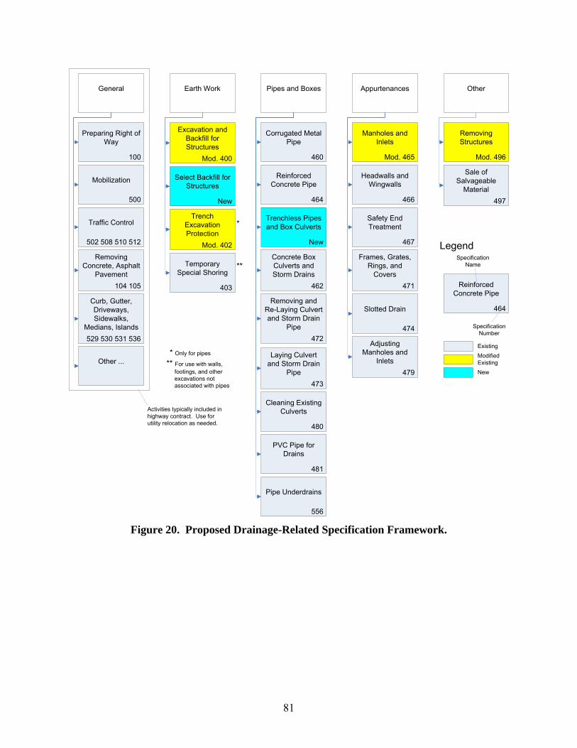
81
Earth Work
Mod. 402
Trench Excavation Protection
403
Temporary Special Shoring
General
500
Mobilization
502 508 510 512
Traffic Control
464
Reinforced Concrete Pipe
Specification Name
Specification Number
100
Preparing Right of Way
Pipes and Boxes Appurtenances
460
Corrugated Metal Pipe
464
Reinforced Concrete Pipe
New
Trenchless Pipes and Box Culverts
462
Concrete Box Culverts and Storm Drains
Mod. 465
Manholes and Inlets
466
Headwalls and Wingwalls
467
Safety End Treatment
471
Frames, Grates, Rings, and
Covers
472
Removing and Re-Laying Culvert and Storm Drain
Pipe
473
Laying Culvert and Storm Drain
Pipe
474
Slotted Drain
479
Adjusting Manholes and
Inlets
480
Cleaning Existing Culverts
481
PVC Pipe for Drains
556
Pipe Underdrains
Other
497
Sale of Salvageable
Material
104 105
Removing Concrete, Asphalt
Pavement
529 530 531 536
Curb, Gutter, Driveways, Sidewalks,
Medians, Islands
Other ...
Legend
* Only for pipes
** For use with walls, footings, and other excavations not associated with pipes
*
**
Mod. 400
Excavation and Backfill for Structures
New
Select Backfill for Structures
Mod. 496
Removing Structures
Existing
New
Modified Existing
Activities typically included in highway contract. Use for utility relocation as needed.
Figure 20. Proposed Drainage-Related Specification Framework.

82
Table 36. Proposed Specification: Excavation and Backfill for Structures.
Specification Number 400 Specification Title Excavation and Backfill for Structures Description Excavate for placement and construction of structures and backfill
for structures. Cut and restore pavement. Previous Specifications 2004 Item 400, “Excavation and Backfill for Structures.” Proposed Changes Delete references to select backfill, e.g., cement stabilized backfill
and flowable backfill. A new special specification (Special Specification XXXX “Select Backfill for Structures,” would cover all non-regular types of backfill. Expand description of bedding specification to account for pipe installation requirements other than those needed for drainage pipe. Note to Specification Writer: Examples of additional bedding specifications include Year 1993 Special Specification 5737 (p. 11-21), NCTCOG construction specifications (Section 504.5, Embedment), and City of Houston Standard Specifications (02317, Excavation and Backfill for Utilities).
Comment Unless specified as a pay item, structural excavation is subsidiary to pertinent items (installation of bridges, boxes, and pipes).
Bid Item Measurement Unit Structural Excavation (Bridge) (if specified) Cubic yard Structural Excavation (Box) (if specified) Cubic yard Structural Excavation (Pipes) (if specified) Cubic yard Cutting and Restoring Pavement Square yard Removing Unstable or Incompressible Material Cubic yard Overexcavation (according to overexcavation table) Cubic yard Specification Writer: Add other select items as indicated on the plans or other design documents
Varies
Subsidiary Item (if specified) Referenced Item Subsidiary to Structural Excavation (Bridge) 400 Bridge construction Structural Excavation (Box) Box installation Structural Excavation (Pipes) Pipe installation Bedding Corresponding item installationConventional Backfill Corresponding item installationSpecification Writer: Add other subsidiary items as indicated on the plans or as required by this specification.

83
Table 37. Proposed Specification: Select Backfill for Structures.
Specification Number XXXX Specification Title Select Backfill for Structures Description Furnish and place select backfill for trench, hole, or other void. Previous Specifications 2004 Item 400, “Excavation and Backfill for Structures.”
2004 Item 401, “Flowable Backfill.” Proposed Changes Create new specification to handle various select backfill types
(such as cement stabilized backfill, flowable backfill, and lime stabilized backfill). Specify payment to include the incremental price above conventional backfill (because, according to Item 400, “Excavation and Backfill for Structures,” conventional backfill is considered subsidiary to the installation of the pipe).
Comment Including cost above regular backfill eliminates redundancy and facilitates unit cost comparisons.
Bid Item Measurement Unit Cement Stabilized Backfill Cubic yard Flowable Backfill Cubic yard Lime Stabilized Backfill Cubic yard Specification Writer: Add other pay items as indicated on the plans or as required by this specification.
Subsidiary Item (if specified) Referenced Item Subsidiary to Loading and Hauling Select Material Select backfill installation Loading and Hauling Waste Material Select backfill installation Disposal of Waste Material Select backfill installation Specification Writer: Add other subsidiary items as indicated on the plans or as required by this specification.
Select backfill installation

84
Table 38. Proposed Specification: Trench Excavation Protection.
Specification Number 402 Specification Title Trench Excavation Protection Description Furnish and place excavation protection for trenches deeper than
5 feet. Previous Specifications 2004 Item 402, “Trench Excavation Protection.” Proposed Changes Modify current standard specification to clarify that protection can
be needed not just to satisfy Occupational Safety and Health Administration (OSHA) requirements, but, also, in general, whenever there is a technical reason (e.g., presence of other utilities, excavation next to the ROW line).
Comment
Bid Item Measurement Unit Trench Excavation Protection Foot
Subsidiary Item (if specified) Referenced Item Subsidiary to

85
Table 39. Proposed Specification: Open-Trench Water Pipe.
Specification Number XXXX Specification Title Open-Trench Water Pipe Description Furnish and install open-trench water pipe and fittings (except
valves, hydrants, and meters, which Special Specification XXXX, “Water Pipe Appurtenances” covers).
Previous Specifications Several, including: 1993 Special Specification 3513, “Water Mains.” 1993 Special Specification 5740, “Water Mains and Service Lines.” 1993 Special Specification 5885, “Water and Sanitary Sewer Systems.”
Proposed Changes Create new specification for open-trench water pipes. Comment Specification includes water mains and service lines, as well as dry
connections to water mains. Tapping sleeve and valves (Special Specification XXXX, “Water Appurtenances”) covers wet connections to water mains.
Bid Item Measurement Unit Open-Trench Water Pipe (Prestressed Concrete) (several diameters)
Foot
Open-Trench Water Pipe (Bar-Wrapped Concrete) (several diameters)
Foot
Open-Trench Water Pipe (Ductile Iron) (several diameters) Foot Open-Trench Water Pipe (Steel) (several diameters) Foot Open-Trench Water Pipe (PVC) (several diameters) Foot Open-Trench Water Pipe (PVC SDR) (several diameters) Foot Open-Trench Water Pipe (HDPE) (several diameters) Foot Open-Trench Water Pipe (Copper) (several diameters) Foot Specification Writer: Add other pay items as indicated on the plans or as required by this specification.
Subsidiary Item (if specified) Referenced Item Subsidiary to Structural Excavation (Pipes) 400 Pipe installation Bedding 400 Pipe installation Fittings (but not Valves or Meters) Pipe installation Backfill 400 Pipe installation Corrosion Control Pipe installation Thrust Restraint Pipe installation Disinfection and Hydrostatic Test Pipe installation Warning Tape for Non-Metallic Pipes Pipe installation Specification Writer: Add other subsidiary items as indicated on the plans or as required by this specification.
Pipe installation

86
Table 40. Proposed Specification: Trenchless Pipes and Box Culverts.
Specification Number XXXX Specification Title Trenchless Pipes and Box Culverts Description Furnish and install pipes and box culverts using trenchless
construction or renewal methods. Previous Specifications Several, including:
2004 Item 476, “Jacking, Boring, or Tunneling Pipe or Box.” 1993 Special Specification 3633, “Horizontal Directional Drilling.” 1993 Special Specification 3666, “Boring 3 Inch PVC.” 1993 Special Specification 4882, “Horizontal Directional Drilling.” 1993 Special Specification 5885, “Water and Sanitary Sewer Systems.” 1993 Special Specification 4059, “Jacking or Boring Concrete Box Culverts.” 1993 Special Specification 4783, “Jacking or Boring Concrete Box Culverts.” 1995 Special Specification 5368, “Boring, Jacking, and Tunneling.”
Proposed Changes Create new specification that addresses limitations of Item 476, “Jacking, Boring, or Tunneling Pipe or Box.” Expand scope of Item 476 to include water and sewer installations. Create specification that reflects recent trends in trenchless construction and renewal methods: - Include requirements for horizontal auger boring (HAB), horizontal directional drilling (HDD), ramming (R), microtunneling (MT), jacking (J), tunneling (T), cured in place pipe (CIPP), folded pipe (FP), coating or lining (CL), sliplining (SL), and pipe replacement (PR). - Use “horizontal auger boring” instead of “jack and bore.”
Comment Specification describes trenchless construction and renewal methods.
Bid Item Measurement Unit Water Pipe (Ductile Iron) (MT) (several diameters) Foot Water Pipe (Ductile Iron) (HDD) (several diameters) Foot Water Pipe (Steel) (HAB) (several diameters) Foot Water Pipe (Steel) (HDD) (several diameters) Foot Water Pipe (Steel) (MT) (several diameters) Foot Water Pipe (Steel) (R) (several diameters) Foot Water Pipe (PVC) (HDD) (several diameters) Foot Water Pipe (PVC SDR) (HDD) (several diameters) Foot Water Pipe (HDPE) (HDD) (several diameters) Foot Gravity Sanitary Sewer Pipe (Reinforced Concrete) (HAB) (several diameters)
Foot
Gravity Sanitary Sewer Pipe (Reinforced Concrete) (MT) (several diameters)
Foot

87
Table 40. Proposed Specification: Trenchless Pipes and Box Culverts (Continued).
Bid Item Measurement Unit Gravity Sanitary Sewer Pipe (PVC) (HDD) (several diameters)
Foot
Gravity Sanitary Sewer Pipe (PE) (HDD) (several diameters) Foot Gravity Sanitary Sewer Pipe (Vitrified Clay) (MT) (several diameters)
Foot
Pressure Sanitary Sewer Pipe (Ductile Iron) (MT) (several diameters)
Foot
Pressure Sanitary Sewer Pipe (Ductile Iron) (HDD) (several diameters)
Foot
Pressure Sanitary Sewer Pipe (PVC) (HDD) (several diameters)
Foot
Concrete Box Culvert (T) (several diameters) Foot Concrete Box Culvert (J) (several diameters) Foot Water Pipe Renewal (CIPP) (several diameters) Foot Water Pipe Renewal (FP) (several diameters) Foot Water Pipe Renewal (CL) (several diameters) Foot Water Pipe Renewal (SL) (several diameters) Foot Water Pipe Renewal (PR) (several diameters) Foot Gravity Sanitary Sewer Pipe Renewal (CIPP) (several diameters)
Foot
Gravity Sanitary Sewer Pipe Renewal (FP) (several diameters)
Foot
Gravity Sanitary Sewer Pipe Renewal (CL) (several diameters)
Foot
Gravity Sanitary Sewer Pipe Renewal (SL) (several diameters)
Foot
Gravity Sanitary Sewer Pipe Renewal (PR) (several diameters)
Foot
Pressure Sanitary Sewer Pipe Renewal (CIPP) (several diameters)
Foot
Pressure Sanitary Sewer Pipe Renewal (FP) (several diameters)
Foot
Pressure Sanitary Sewer Pipe Renewal (CL) (several diameters)
Foot
Pressure Sanitary Sewer Pipe Renewal (SL) (several diameters)
Foot
Pressure Sanitary Sewer Pipe Renewal (PR) (several diameters)
Foot
Specification Writer: Add other pay items as indicated on the plans or as required by this specification.
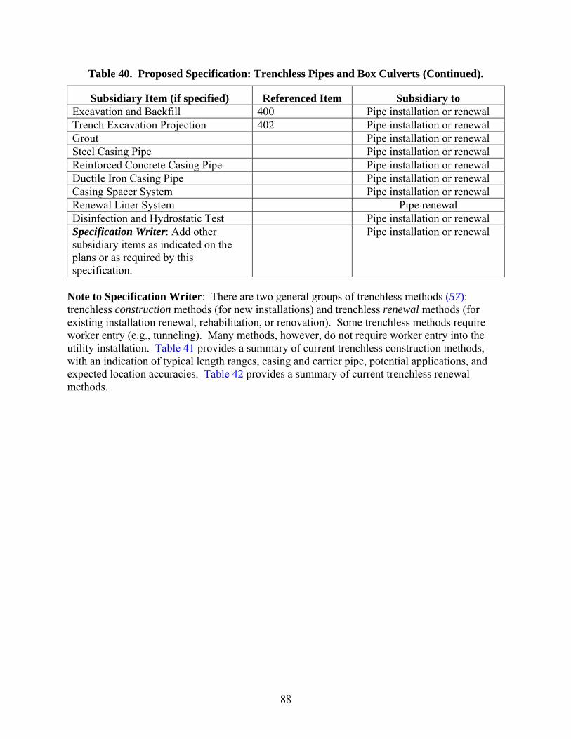
88
Table 40. Proposed Specification: Trenchless Pipes and Box Culverts (Continued).
Subsidiary Item (if specified) Referenced Item Subsidiary to Excavation and Backfill 400 Pipe installation or renewal Trench Excavation Projection 402 Pipe installation or renewal Grout Pipe installation or renewal Steel Casing Pipe Pipe installation or renewal Reinforced Concrete Casing Pipe Pipe installation or renewal Ductile Iron Casing Pipe Pipe installation or renewal Casing Spacer System Pipe installation or renewal Renewal Liner System Pipe renewal Disinfection and Hydrostatic Test Pipe installation or renewal Specification Writer: Add other subsidiary items as indicated on the plans or as required by this specification.
Pipe installation or renewal
Note to Specification Writer: There are two general groups of trenchless methods ( 57): trenchless construction methods (for new installations) and trenchless renewal methods (for existing installation renewal, rehabilitation, or renovation). Some trenchless methods require worker entry (e.g., tunneling). Many methods, however, do not require worker entry into the utility installation. Table 41 provides a summary of current trenchless construction methods, with an indication of typical length ranges, casing and carrier pipe, potential applications, and expected location accuracies. Table 42 provides a summary of current trenchless renewal methods.

Table 41. Summary of Current Trenchless Construction Methods (adapted from [ 57]). Trenchless
Construction Method Main Characteristics Diameter
Range (in)Maximum Length (ft)
(Casing) Pipe Typical Application Typical Accuracy
Horizontal auger boring (HAB) (also known as “boring” or “jack and bore”): Auger boring Jacks a steel casing from a drive shaft or pit
while rotating flight auger removes spoil cut with cutting head. After installing casing, carrier pipe is usually installed and annular space is filled with grout.
4 – 60 600 Steel Road and rail crossing ±1% of bore length
Auger boring steered on grade
Enables grade control only, usually with a water level and a water pipe running along the top of the casing.
4 – 60 600 Steel Pressure and gravity ±12 inches
Auger boring steered on line and grade
Enables horizontal and vertical control (could be mechanical or electrical).
4 – 60 600 Steel Pressure and gravity Depends on steering control technology
Pilot tube auger boring Combines a horizontal auger boring machine with a pilot head guidance mechanism. Pilot tubes are installed behind the steering head. After the steering head has reached the reception shaft, a reaming head and auger tubes are installed behind the pilot tubes.
4 – 60 600 Steel Pressure and gravity Depends on steering control technology
Horizontal directional drilling (HDD): Mini HDD Involves drilling of pilot hole using a steerable
drill head, and backreaming to increase pilot hole diameter and pulling of carrier pipe. Reaming options include back reaming and forward reaming. A surface inclined launcher (8 – 18 degrees) drills pilot hole. Maximum depth is typically 15 feet. Tracking systems include walk-over (battery-powered transmitter, receiver, and remote display) and wire line (transmitter is wire-powered), electromagnetic telemetry, and mud-pulse telemetry.
2 – 12 600 Steel, PVC, clay, polyethylene, fiberglass reinforces polyester
Pressure/cable Varies. 10 feet (left or right) and -10 to +30 feet along main axis for pilot hole exit point is not unusual.
Midi HDD Maximum depth is typically 75 feet. 12 – 24 1,000 Steel, polyethylene, ductile iron
Pressure Varies. 10 feet (left or right) and -10 to +30 feet along main axis for pilot hole exit point is not unusual.
Maxi HDD Maximum depth is typically 200 feet. Several passes of back reaming may be necessary to enlarge hole to desired size.
24 – 48 6,000 Steel, polyethylene Pressure Varies. 10 feet (left or right) and -10 to +30 feet along main axis for pilot hole exit point is not unusual.
89
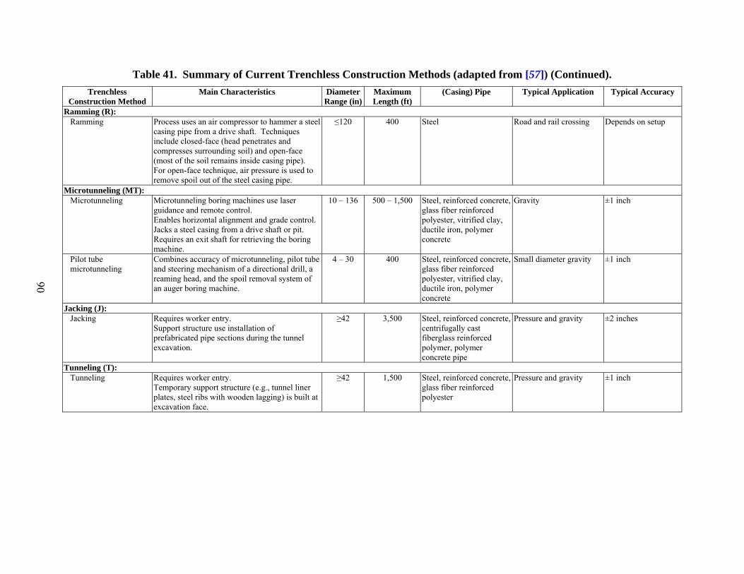
Table 41. Summary of Current Trenchless Construction Methods (adapted from [ 57]) (Continued). Trenchless
Construction Method Main Characteristics Diameter
Range (in)Maximum Length (ft)
(Casing) Pipe Typical Application Typical Accuracy
Ramming (R): Ramming Process uses an air compressor to hammer a steel
casing pipe from a drive shaft. Techniques include closed-face (head penetrates and compresses surrounding soil) and open-face (most of the soil remains inside casing pipe). For open-face technique, air pressure is used to remove spoil out of the steel casing pipe.
≤120 400 Steel Road and rail crossing Depends on setup
Microtunneling (MT): Microtunneling Microtunneling boring machines use laser
guidance and remote control. Enables horizontal alignment and grade control. Jacks a steel casing from a drive shaft or pit. Requires an exit shaft for retrieving the boring machine.
10 – 136 500 – 1,500 Steel, reinforced concrete, glass fiber reinforced polyester, vitrified clay, ductile iron, polymer concrete
Gravity ±1 inch
Pilot tube microtunneling
Combines accuracy of microtunneling, pilot tube and steering mechanism of a directional drill, a reaming head, and the spoil removal system of an auger boring machine.
4 – 30 400 Steel, reinforced concrete, glass fiber reinforced polyester, vitrified clay, ductile iron, polymer concrete
Small diameter gravity ±1 inch
Jacking (J): Jacking Requires worker entry.
Support structure use installation of prefabricated pipe sections during the tunnel excavation.
≥42 3,500 Steel, reinforced concrete, centrifugally cast fiberglass reinforced polymer, polymer concrete pipe
Pressure and gravity ±2 inches
Tunneling (T): Tunneling Requires worker entry.
Temporary support structure (e.g., tunnel liner plates, steel ribs with wooden lagging) is built at excavation face.
≥42 1,500 Steel, reinforced concrete, glass fiber reinforced polyester
Pressure and gravity ±1 inch
90

Table 42. Summary of Current Trenchless Renewal Methods (adapted from [ 57]). Trenchless Renewal
Method Main Characteristics Diameter
Range (in)Maximum Length (ft)
Liner Material Typical Application
Cured in place pipe (CIPP): Cured in place pipe Involves insertion of resin-impregnated fabric
tube into existing pipe. Curing involves the use of hot water or air. Some loss of cross sectional area. Can provide structural support.
4 – 108 3,000 Thermoset resin/fabric composite
Gravity and pressure
Folded pipe (FP): Thermoformed pipe Involves insertion of folded pipe and subsequent
heating to thermoform pipe section. Some loss of cross sectional area. Can provide structural support.
4 – 30 1,500 High density polyethylene (HDPE), PVC
Gravity and pressure
Mechanically folded Involves insertion of folded pipe and subsequent pressurization with water at ambient temperature. Can provide structural support.
3 – 63 1,000 HDPE, medium density polyethylene
Gravity and pressure
Reduced diameter Involves insertion of reduced diameter pipe and subsequent expansion to fit existing pipe. Can provide structural support.
3 – 63 1,000 HDPE, medium density polyethylene
Gravity and pressure
Coating or lining (CL): Coating or lining Involves spraying of a thin mortar lining or a
resin coating. Some loss of cross sectional area. Structural support is typically limited.
3 – 180 1,000 Epoxy, polyester, silicone, vinyl ester, polyurethane, mortar
Gravity and pressure
Sliplining (SL): Segmental Involves inserting new pipe segments into
existing pipe. Grout is applied to space between the two pipes. Cross sectional area loss can be significant.
24 – 160 1,000 Polyethylene, polypropylene, PVC, glass fiber reinforced polymer
Gravity and pressure
Continuous Involves inserting continuous new pipe into existing pipe.
4 – 63 1,000 Polyethylene, polypropylene, PVC, polyethylene/ethylene propylene diene monomer
Gravity and pressure
Panel lining Normally used to renew large diameter pipes. Can be used on noncircular pipes.
>48 Varies Glass fiber reinforced polymer
Gravity
Spiral wound Composite system made up of PVC liner and grout. Produces an integrated structure between old pipe and new composite system
6 – 108 1,000 Polyethylene, polypropylene, PVC, polyvinylidene diflouride membranes
Gravity
Formed-in-place Can be used on noncircular shapes 8 – 144 Varies Polyvinyl chloride, HDPE Gravity
91
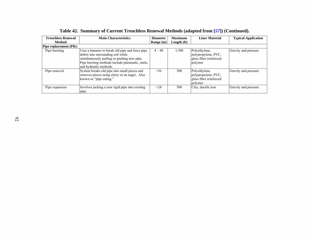
Table 42. Summary of Current Trenchless Renewal Methods (adapted from [ 57]) (Continued). Trenchless Renewal
Method Main Characteristics Diameter
Range (in)Maximum Length (ft)
Liner Material Typical Application
Pipe replacement (PR): Pipe bursting Uses a hammer to break old pipe and force pipe
debris into surrounding soil while simultaneously pulling or pushing new pipe. Pipe bursting methods include pneumatic, static, and hydraulic methods.
4 – 48 1,500 Polyethylene, polypropylene, PVC, glass fiber reinforced polymer
Gravity and pressure
Pipe removal System breaks old pipe into small pieces and removes pieces using slurry or an auger. Also known as “pipe eating.”
<36 300 Polyethylene, polypropylene, PVC, glass fiber reinforced polymer
Gravity and pressure
Pipe expansion Involves jacking a new rigid pipe into existing pipe.
<24 500 Clay, ductile iron Gravity and pressure
92
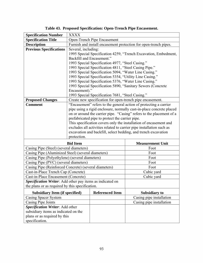
93
Table 43. Proposed Specification: Open-Trench Pipe Encasement.
Specification Number XXXX Specification Title Open-Trench Pipe Encasement Description Furnish and install encasement protection for open-trench pipes. Previous Specifications Several, including:
1995 Special Specification 4259, “Trench Excavation, Embedment, Backfill and Encasement.” 1993 Special Specification 4977, “Steel Casing.” 1993 Special Specification 4811, “Steel Casing Pipe.” 1993 Special Specification 5094, “Water Line Casing.” 1993 Special Specification 5354, “Utility Line Casing.” 1993 Special Specification 5376, “Water Line Casing.” 1993 Special Specification 5890, “Sanitary Sewers (Concrete Encasement).” 1993 Special Specification 7681, “Steel Casing.”
Proposed Changes Create new specification for open-trench pipe encasement. Comment “Encasement” refers to the general action of protecting a carrier
pipe using a rigid enclosure, normally cast-in-place concrete placed on or around the carrier pipe. “Casing” refers to the placement of a prefabricated pipe to protect the carrier pipe. This specification covers only the installation of encasement and excludes all activities related to carrier pipe installation such as excavation and backfill, select bedding, and trench excavation protection.
Bid Item Measurement Unit Casing Pipe (Steel) (several diameters) Foot Casing Pipe (Aluminized Steel) (several diameters) Foot Casing Pipe (Polyethylene) (several diameters) Foot Casing Pipe (PVC) (several diameters) Foot Casing Pipe (Reinforced Concrete) (several diameters) Foot Cast-in-Place Trench Cap (Concrete) Cubic yard Cast-in-Place Encasement (Concrete) Cubic yard Specification Writer: Add other pay items as indicated on the plans or as required by this specification.
Subsidiary Item (if specified) Referenced Item Subsidiary to Casing Spacer System Casing pipe installation Casing Pipe Joints Casing pipe installation Specification Writer: Add other subsidiary items as indicated on the plans or as required by this specification.
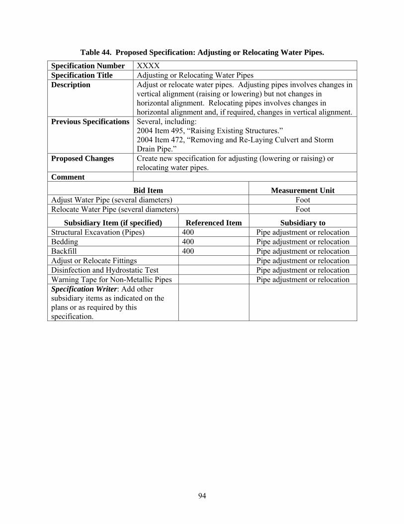
94
Table 44. Proposed Specification: Adjusting or Relocating Water Pipes.
Specification Number XXXX Specification Title Adjusting or Relocating Water Pipes Description Adjust or relocate water pipes. Adjusting pipes involves changes in
vertical alignment (raising or lowering) but not changes in horizontal alignment. Relocating pipes involves changes in horizontal alignment and, if required, changes in vertical alignment.
Previous Specifications Several, including: 2004 Item 495, “Raising Existing Structures.” 2004 Item 472, “Removing and Re-Laying Culvert and Storm Drain Pipe.”
Proposed Changes Create new specification for adjusting (lowering or raising) or relocating water pipes.
Comment
Bid Item Measurement Unit Adjust Water Pipe (several diameters) Foot Relocate Water Pipe (several diameters) Foot
Subsidiary Item (if specified) Referenced Item Subsidiary to Structural Excavation (Pipes) 400 Pipe adjustment or relocation Bedding 400 Pipe adjustment or relocation Backfill 400 Pipe adjustment or relocation Adjust or Relocate Fittings Pipe adjustment or relocation Disinfection and Hydrostatic Test Pipe adjustment or relocation Warning Tape for Non-Metallic Pipes Pipe adjustment or relocation Specification Writer: Add other subsidiary items as indicated on the plans or as required by this specification.

95
Table 45. Proposed Specification: Water Appurtenances.
Specification Number XXXX Specification Title Water Appurtenances Description Furnish and install appurtenances in connection with the installation
of water lines. Previous Specifications Several, including:
1993 Special Specification 3513, “Water Mains.” 1993 Special Specification 3514, “Water Mains and Sanitary Sewers.” 1993 Special Specification 3596, “Water and Wastewater Infrastructures and Appurtenances.” 1993 Special Specification 5740, “Water Mains and Service Lines.” 1993 Special Specification 5885, “Water and Sanitary Sewer Systems.”
Proposed Changes Create new specification for water appurtenances. Comment
Bid Item Measurement Unit Water Meter (several diameters) Each Water Meter Box (several sizes) Each Water Valve (Air Release & Vacuum) (several diameters) Each Water Valve (Butterfly) (several diameters) Each Water Valve (Gate) (several diameters) Each Water Valve (Tap Sleeve and Valve) (several diameters) Each Blow Off Assembly (several diameters) Each Hydrant (several type assemblies) Each Pressure Reducing Station Each Specification Writer: Add other pay items as indicated on the plans or as required by this specification.
Subsidiary Item (if specified) Referenced Item Subsidiary to Structural Excavation 400 Appurtenance installation Bedding 400 Appurtenance installation Backfill 400 Appurtenance installation Valve Cover, Stack, and Box Valve installation Disinfection and Hydrostatic Test Appurtenance installation Specification Writer: Add other subsidiary items as indicated on the plans or as required by this specification.
Appurtenance installation

96
Table 46. Proposed Specification: Adjusting or Relocating Pipe Appurtenances.
Specification Number XXXX Specification Title Adjusting or Relocating Pipe Appurtenances Description Adjust or relocate pipe appurtenances. Adjusting pipe
appurtenances involves changes in vertical alignment (raising or lowering) but not changes in horizontal alignment. Relocating pipe appurtenances involves changes in horizontal alignment and, if required, changes in vertical alignment.
Previous Specifications Several, including: 1993 Special Specification 5121, “Vertical Adjustment of Water Valve Cover and Valve Stack.” 1993 Special Specification 5126, “Adjustment of Fire Hydrants.” 1993 Special Specification 5298, “Adjustment of Water Meter Box and Flush Point.” 1993 Special Specification 5511, “Relocate Existing Meters and Meter Boxes.” 1993 Special Specification 5510, “Remove and Relocate Fire Hydrant.” 2004 Special Specification 5257, “Routine Water Appurtenance Adjustments.” 2004 Item 472, “Removing and Re-laying Culvert and Storm Drain Pipe.”
Proposed Changes Create new specification for adjusting (raising or lowering) or relocating pipe appurtenances.
Comment This specification covers both water and sanitary sewer appurtenances.
Bid Item Measurement Unit Adjust Water Meter and Meter Box Each Adjust Water Valve Each Adjust Hydrant Each Relocate Water Meter and Meter Box Each Relocate Water Valve Each Relocate Hydrant Each Adjust Sanitary Sewer Valve Each Adjust Sanitary Sewer Pipe Cleanout Each Adjust Sanitary Sewer Pump Each Adjust Sanitary Sewer Valve Each Adjust Sanitary Sewer Pipe Cleanout Each Adjust Sanitary Sewer Pump Each Specification Writer: Add other pay items as indicated on the plans or as required by this specification.

97
Table 46. Proposed Specification: Adjusting or Relocating Pipe Appurtenances (Continued).
Subsidiary Item (if specified) Referenced Item Subsidiary to Structural Excavation (Pipes) 400 Appurtenance adjustment or
relocation Bedding 400 Appurtenance adjustment or
relocation Backfill 400 Appurtenance adjustment or
relocation Adjust or Relocate Fittings Appurtenance adjustment or
relocation Adjust or Relocate Valve Cover, Stack, or Cover
Valve adjustment or relocation
Disinfection and Hydrostatic Test Appurtenance adjustment or relocation
Specification Writer: Add other subsidiary items as indicated on the plans or as required by this specification.

98
Table 47. Proposed Specification: Manholes and Inlets.
Specification Number 465 Specification Title Manholes and Inlets Description Construct manholes and inlets, complete in place or to the stage
detailed, including furnishing and installing frames, grates, rings, and covers. Drainage junction boxes are classified as manholes.
Previous Specifications 2004 Item 465, “Manholes and Inlets.” Proposed Changes Modify specification to ensure compatibility with water and
sanitary sewer manhole characteristics and requirements. Add fiberglass and connectors to the list of materials. Add testing to the construction section. Add bid items for manholes and inlets to account for different types and depths of manholes.
Comment
Bid Item Measurement Unit Manhole (several types) (Complete) (several depths) Each Manhole (several types) (Stage I) (several depths) Each Manhole (several types) (Stage II) (several depths) Each Inlet (several types) (Complete) (several depths) Each Inlet (several types) (Stage I) (several depths) Each Inlet (several types) (Stage II) (several depths) Each Inlet Extension (several types) Each Specification Writer: Add other pay items as indicated on the plans or as required by this specification.
Subsidiary Item (if specified) Referenced Item Subsidiary to Excavation 400 Manhole or Inlet Installation Backfill 400 Manhole or Inlet Installation Testing Manhole or Inlet Installation Seals Manhole or Inlet Installation Extensions Manhole or Inlet Installation Covers 471 Manhole or Inlet Installation Rings 471 Manhole or Inlet Installation Grates 471 Manhole or Inlet Installation Frames 471 Manhole or Inlet Installation Specification Writer: Add other subsidiary items as indicated on the plans or as required by this specification.

99
Table 48. Proposed Specification: Removing Structures.
Specification Number 496 Specification Title Removing Structures Description Remove and either dispose of or salvage structures. Previous Specifications 2004 Item 496, “Removing Structures.”
1993 Special Specification 5062, “Salvaging Water Lines, Sanitary Sewer Lines, Fire Hydrants, Valves and Fittings.” 1993 Special Specification 5000, “Transporting Salvaged Items.” 1993 Special Specification 8326, “Remove Rigid Metal Conduit.” 1993 Special Specification 8634, “Remove Rigid Metal Conduit.”
Proposed Changes Modify specification to include the removal of utility appurtenances.
Comment Removing water appurtenances includes removing valves, meters, meter boxes, and hydrants. Removing sanitary sewer appurtenances includes removing valves, cleanouts, and pumps. All other fittings are subsidiary to pipe removal. Specification Writer: The proposed modifications do not include a provision for asbestos cement pipe because TxDOT is revising Items 1 through 9 to more explicitly account for the presence of asbestos at the job site.
Bid Item Measurement Unit Removing Structures (Pipe) (several diameters) Foot Removing Structures (Water Appurtenance) Each Removing Structures (Sanitary Sewer Appurtenance) Each Removing Structures (Concrete, Brick, or Stone Structures) Each Removing Structures (Steel) Each Removing Structures (Timber) Each Specification Writer: Add other pay items as indicated on the plans or as required by this specification.
Subsidiary Item (if specified) Referenced Item Subsidiary to Structural Excavation (Pipes) 400 Item removal Backfill 400 Item removal Remove Pipe Fittings Pipe removal Specification Writer: Add other subsidiary items as indicated on the plans or as required by this specification.

100
Table 49. Proposed Specification: Abandoning Structures.
Specification Number XXXX Specification Title Abandoning Structures Description Abandon and permanently remove from service utility structures
such as pipes, manholes, and underground fuel storage tank systems.
Previous Specifications 1993 Special Specification 7321, “Abandonment and Permanent Removal from Service of Underground Fuel Storage Tank Systems.” 1993 Special Specification 7328, “Abandonment and Permanent Removal from Service of Underground Fuel Storage Tank Systems.” 1993 Special Specification 5740, “Water Mains and Service Lines.”
Proposed Changes Create new specification for abandoning and permanently removing utility structures from service.
Comment
Bid Item Measurement Unit Abandon Pipe (Cut and Plug End) (several diameters) Each Abandon Pipe (Grout Fill) Cubic yard Abandon Manhole (Grout Fill) Cubic yard Abandon Underground Fuel Storage Tank System Lump sum Specification Writer: Add other pay items as indicated on the plans or as required by this specification.
Subsidiary Item (if specified) Referenced Item Subsidiary to Abandon Appurtenance Abandon Pipe Specification Writer: Add other subsidiary items as indicated on the plans or as required by this specification.

101
Table 50. Proposed Specification: Open-Trench Gravity Sanitary Sewer Pipe.
Specification Number XXXX Specification Title Open-Trench Gravity Sanitary Sewer Pipe Description Furnish and install open-trench gravity sanitary sewer pipe and
fittings (except valves which Special Specification XXXX, “Sanitary Sewer Pipe Appurtenances” covers).
Previous Specifications Several, including: 1993 Special Specification 3514, “Water Mains and Sanitary Sewers.” 1993 Special Specification 5885, “Water and Sanitary Sewer Systems.” 2004 Special Specification 5095, “Sanitary Sewer Mains.”
Proposed Changes Create new specification for open-trench gravity sanitary sewer pipes.
Comment
Bid Item Measurement Unit Open-Trench Gravity Sanitary Sewer Pipe (Reinforced Concrete) (several diameters)
Foot
Open-Trench Gravity Sanitary Sewer Pipe (Nonreinforced Concrete) (several diameters, typically less than 12 inches)
Foot
Open-Trench Gravity Sanitary Sewer Pipe (PVC) (several diameters)
Foot
Open-Trench Gravity Sanitary Sewer Pipe (PE) (several diameters)
Foot
Open-Trench Gravity Sanitary Sewer Pipe (Fiberglass) (several diameters)
Foot
Open-Trench Gravity Sanitary Sewer Pipe (Vitrified Clay) (several diameters)
Foot
Specification Writer: Add other pay items as indicated on the plans or as required by this specification.
Subsidiary Item (if specified) Referenced Item Subsidiary to Structural Excavation (Pipes) 400 Pipe installation Bedding 400 Pipe installation Fittings Pipe installation Backfill 400 Pipe installation Corrosion Control Pipe installation Testing Pipe installation Warning Tape for Non-Metallic Pipes Pipe installation Specification Writer: Add other subsidiary items as indicated on the plans or as required by this specification.
Pipe installation

102
Table 51. Proposed Specification: Open-Trench Pressure Sanitary Sewer Pipe.
Specification Number XXXX Specification Title Open-Trench Pressure Sanitary Sewer Pipe Description Furnish and install open-trench pressure sanitary sewer pipe and
fittings (except valves, which Special Specification XXXX, “Sanitary Sewer Pipe Appurtenances” covers).
Previous Specifications Several, including: 1993 Special Specification 4731, “Concrete Thrust Block.” 1993 Special Specification 5885, “Water and Sanitary Sewer Systems.” 1993 Special Specification 5521, “Sanitary Sewer.” 2004 Special Specification 5095, “Sanitary Sewer Mains.” 2004 Special Specification 5195, “Sanitary Sewer.” 2004 Special Specification 5289, “Sanitary Sewer.”
Proposed Changes Create new specification for open-trench pressure sanitary sewer pipes.
Comment
Bid Item Measurement Unit Open-Trench Pressure Sanitary Sewer Pipe (Pre-stressed Concrete) (several diameters)
Foot
Open-Trench Pressure Sanitary Sewer Pipe (Bar-Wrapped Concrete) (several diameters)
Foot
Open-Trench Pressure Sanitary Sewer Pipe (Ductile Iron) (several diameters)
Foot
Open-Trench Pressure Sanitary Sewer Pipe (PVC) (several diameters)
Foot
Open-Trench Pressure Sanitary Sewer Pipe (Fiberglass) (several diameters)
Foot
Specification Writer: Add other pay items as indicated on the plans or as required by this specification.
Subsidiary Item (if specified) Referenced Item Subsidiary to Structural Excavation (Pipes) 400 Pipe installation Bedding 400 Pipe installation Fittings (but not Valves) Pipe installation Backfill 400 Pipe installation Corrosion Control Pipe installation Thrust Restraint Pipe installation Leakage Testing Pipe installation Warning Tape for Non-Metallic Pipes Pipe installation Specification Writer: Add other subsidiary items as indicated on the plans or as required by this specification.
Pipe installation

103
Table 52. Proposed Specification: Adjusting or Relocating Sanitary Sewer Pipes.
Specification Number XXXX Specification Title Adjusting or Relocating Sanitary Sewer Pipes Description Adjust or relocate sanitary sewer pipes. Adjusting pipes involves
changes in vertical alignment (raising or lowering) but not changes in horizontal alignment. Relocating pipes involves changes in horizontal alignment and, if required, changes in vertical alignment.
Previous Specifications Several, including: 2004 Item 495, “Raising Existing Structures.” 2004 Item 472, “Removing and Re-Laying Culvert and Storm Drain Pipe.” 1993 Special Specification 5570, “Relocate Sanitary Sewer.”
Proposed Changes Create new specification for adjusting (raising or lowering) or relocating sanitary sewer pipes.
Comment
Bid Item Measurement Unit Adjust Sanitary Sewer Pipe (several diameters) Foot Relocate Sanitary Sewer Pipe (several diameters) Foot Specification Writer: Add other pay items as indicated on the plans or as required by this specification.
Subsidiary Item (if specified) Referenced Item Subsidiary to Structural Excavation (Pipes) 400 Pipe adjustment or relocation Bedding 400 Pipe adjustment or relocation Backfill 400 Pipe adjustment or relocation Adjust or Relocate Fittings Pipe adjustment or relocation Specification Writer: Add other subsidiary items as indicated on the plans or as required by this specification.

104
Table 53. Proposed Specification: Sanitary Sewer Appurtenances.
Specification Number XXXX Specification Title Sanitary Sewer Appurtenances Description Furnish and install appurtenances for sanitary sewer lines. Previous Specifications Several, including:
1993 Special Specification 3596, “Water and Wastewater Infrastructure and Appurtenances.” 1993 Special Specification 5493, “Water Mains and Wastewater Appurtenances.” 2004 Special Specification 5033, “Water and Wastewater Main Appurtenances.” 2004 Special specification 5061, “Water and Wastewater Main Appurtenances.”
Proposed Changes Create new specification for sanitary sewer appurtenances. Comment
Bid Item Measurement Unit Sanitary Sewer Gate Valve (several diameters) Each Sanitary Sewer Pipe Cleanout (several sewer line diameters) Each Sanitary Sewer Tap Valve and Sleeve (several diameters) Each Sanitary Sewer Pump (several types) (several diameters) Each Specification Writer: Add other pay items as indicated on the plans or as required by this specification.
Subsidiary Item (if specified) Referenced Item Subsidiary to Structural Excavation 400 Appurtenance installation Bedding 400 Appurtenance installation Backfill 400 Appurtenance installation Valve Cover, Stack, and Box Valve installation Testing Appurtenance installation Specification Writer: Add other subsidiary items as indicated on the plans or as required by this specification.
Appurtenance installation
105
CHAPTER 5. UTILITY INSTALLATION SPECIAL PROVISIONS
INTRODUCTION
This chapter summarizes the results of an analysis conducted to determine the degree to which special provisions comply with the UAR and the TxDOT Utility Manual ( 1, 2). The analysis includes both special provisions attached to utility permits and special provisions in connection with utility relocation activities. In the case of special provisions attached to utility permits, the discussion includes a brief description of the utility permitting process at TxDOT with a focus on the approval step and special provisions that may be attached to approval forms, a description of instances where individual special provisions do not meet or exceed current rules and regulations, and an assessment of the need to continue with the practice of attaching special provisions to utility permit approvals at TxDOT. In the case of utility relocation special provisions, the discussion expands on work already completed internally at TxDOT that resulted in a policy memorandum from the TxDOT administration ( 58).
UTILITY PERMIT SPECIAL PROVISIONS
The UAR and the TxDOT Utility Manual govern the accommodation of utility facilities within the ROW of state highways in Texas ( 1, 2). The rules and guidelines are the result of a federal mandate that requires states to submit a statement to FHWA on the authority of utilities to use and occupy the state highway ROW, the power of the state department of transportation (DOT) to regulate such use, and the policies the state DOT uses for accommodating utilities within the ROW of federal-aid highways under its jurisdiction ( 24). The rules, which trace their origin to utility accommodation policies and guides AASHTO developed, prescribe minimums relative to the accommodation, location, installation, adjustment, and maintenance of utility facilities within the state ROW ( 59, 60). However, the rules also establish that where industry or governmental codes, orders, or laws require utilities to provide a higher degree of protection than provided in the UAR, such regulations and laws take precedence ( 1). Several other guidelines, in addition to AASHTO’s utility accommodation policy, provide guidance concerning the accommodation of utility facilities within the highway ROW. Examples include AASHTO’s guidance on accommodation of telecommunication utilities ( 61), AASHTO’s policy on geometric design (also known as the “Green Book”) ( 62), AASHTO’s roadside design guide ( 63), as well as FHWA’s guidelines on utility relocation and accommodation ( 64, 65, 66). The UAR apply to all utility installations within the state highway ROW. However, special protocols and documentation typically apply to Notices of Proposed Installation (NOPIs) (or “utility permit applications” as TxDOT and utility company officials frequently call those documents). The Utility Manual ( 2) outlines the general procedure and documentation required for the submission, review, and approval of NOPIs. Review and approval of these notices is the responsibility of the districts, except in the case of proposed utility installations on bridges, attachments to highway structures, or exceptions to the UAR. Districts routinely attach special provisions to proposed installation approvals. With this information, districts conduct an inspection of the progress of the work by utility companies (or their contractors) in the field.

106
Special Provision Analysis
The researchers contacted all 25 districts concerning NOPI special provision practices. A total of 18 districts provided copies of special provisions. A preliminary review of the special provision documents found many cases where districts apparently used special provisions as a reminder of current rules and regulations. For this reason, the analysis focused on determining the degree to which, and in what way, special provisions replicated information already included in the UAR and other regulations. For convenience, the researchers classified special provisions into three categories:
• Repetitive. A special provision that contained essentially the same requirements as the current version of the UAR and/or other regulation sources.
• More stringent. A special provision that exceeded the requirements included in the current version of the UAR or that included requirements not found in the UAR.
• In conflict or potential conflict with the UAR. A special provision that contained less stringent requirements than the current version of the UAR or that might cause confusion in its interpretation.
In most cases, it was not possible to classify a special provision document as a whole into one of the three categories described above. Typically, only certain phrases or parts of phrases within a particular special provision document were either in conflict with the UAR or were more stringent than the UAR. Readers should also be aware that the current UAR are the result of several changes that took effect in March 2005 ( 1). They contain more stringent requirements than the previous version, which many districts had used to produce the special provisions the researchers reviewed. It is possible that, as of this writing, most of the districts may have already modified their special provisions to reflect the requirements of the current version of the UAR. Conversely, it is also possible that some special provisions might reflect local conditions that require exceptions to the UAR, therefore lowering the standard specified by the statewide UAR. Further, the researchers reviewed samples of special provisions the districts provided, which made it challenging to determine whether the special provisions applied to all utility installations in those districts or only in special cases. For this analysis, the researchers classified special provisions into topics. This chapter covers the following topics (although readers should be aware that the list is not comprehensive and only provides a reference to the analysis):
• general utility location and encasement; • boring; • trenching and backfilling; • water; • sanitary sewers; • support structures and aerial installations; • vegetation, erosion control, and cleanup; and • traffic control and safety.

107
General Utility Location and Encasement
This section covers special provisions related to general utility location and encasement issues. Subsequent sections cover specific requirements for individual types of installations such as water, sanitary sewers, and support structures and aerial installations. Relevant text from the UAR on the topic of general utility location and encasement follows ( 1). §21.37. Design. (b) Location.
(1) Utility lines shall be located to avoid or minimize the need for adjustment for future highway projects and improvements, to allow other utilities equal access in the right of way, and to permit access to utility facilities for their maintenance with minimum interference to highway traffic.
(2) Longitudinal installations, if allowed, shall be located on uniform alignments to the right of way line to provide space for future highway construction and possible future utility installations.
(3) New utility lines crossing the highway shall be installed at approximately 90 degrees to the centerline of the highway.
(4) The horizontal and vertical location of utility lines shall conform with §21.41(c) of this subchapter, consistent with the clearances applicable to all roadside obstacles. No aboveground fixed objects will be allowed in the horizontal clearance.
(6) Utilities on controlled access highways or freeways shall be located to permit maintenance of the utility by access from frontage roads, nearby or adjacent roads and streets, or trails along or near the right of way line without access from the main lanes or ramps. Utilities shall not be located longitudinally in the center median or outer separation of controlled access highways or freeways.
(7) On highways with frontage roads, longitudinal utility installations may be located between the frontage road and the right of way line. Utility lines shall not be placed or allowed to remain in the center median, outer separation, or beneath any pavement, including shoulders.
(8) When a longitudinal installation is proposed within existing access denial lines of a controlled access highway or freeway without frontage roads and meets the conditions of §21.35 of this subchapter, the department may establish a utility strip, specific to the requesting utility, designating the area of use, occupancy, and access. All existing and proposed fences shall be located at the freeway right of way line. Denial of access regarding property adjoining the right of way line will not be altered.
§21.40. Underground Utilities. (a) General.
(1) Encasement. (A) Underground utilities crossing the highway shall be encased in the interest of safety, protection of the
utility, protection of the highway, and for access to the utility. Casing shall consist of a pipe or other separate structure around and outside the carrier line. The utility must demonstrate that the casing will be adequate for the expected loads and stresses.
(B) Casing pipe shall be steel, concrete, or plastic pipe as approved by the district, except that if horizontal directional drilling is used to place the casing, high-density polyethylene (HDPE) pipe must be used in place of plastic pipe.
(C) Encasement may be of metallic or non-metallic material. Encasement material shall be designed to support the load of the highway and superimposed loads thereon, including that of construction machinery. The strength of the encasement material shall equal or exceed structural requirements for drainage culverts and it shall be composed of material of satisfactory durability for conditions to which it may be subjected. The length of any encasement under the roadway shall be provided from top of backslope to top of backslope for cut sections, five feet beyond the toe of slope for fill sections, and five feet beyond the face of the curb for curb sections. These lengths of encasement include areas under center medians and outer separations, unless otherwise specifically addressed in subsections (b)-(f) of this section.
(D) The department will provide an example graphic upon request of a typical section showing encasement lengths.

108
(2) Depth. Where placements at the depths in this section are impractical or where unusual conditions exist, the department may allow installations at a lesser depth, but will require other means of protection, including encasement or the placement of a reinforced concrete slab. Reinforced concrete slabs or caps shall meet the following standards:
(A) width--five feet, or three times the diameter of the pipe, whichever is greater; (B) thickness--six inches, at minimum; (C) reinforcement--#4 bars at 12 inch centers each way or equivalent reinforcement; and (D) cover--no less than six inches of sand or equivalent cushion between the bottom of the slab/cap and the top
of the pipe. (5) Nonmetallic pipe detection. Where nonmetallic pipe is installed, whether longitudinally or at a crossing, a
durable metal wire or other district-approved means of detection shall be concurrently installed. The following are examples of special provision text that replicates UAR requirements:
• Installations shall be placed uniformly along the right of way line on longitudinal sections “as dimensioned” and approved on the notice from and specified on the plans.
• Longitudinal lines near ROW line. • Depth of Cover Longitudinal: Located on uniform alignment as near as practicable to the ROW (special
provision mixes depth of cover requirements with longitudinal alignment requirements). • Longitudinal lines shall be placed as near as feasible to the ROW line and crossings shall be approximately
perpendicular. • Location - Crossing approximately perpendicular. • Crossings approximately perpendicular. • Crossings should be at approximate right angles to the highway to the extent reasonable and feasible. • The length of encasement shall extend under center medians and from toe of backslope for cut sections (or
5 feet beyond the toe of front slope for fill sections, or face of curb) of all roadways including side streets. • Encasement: From top of backslope to top of back slope plus 5 feet on each side for fill sections
(recommended that the line be encased from ROW to ROW to add additional protection to the installation). • Encasement: Lines to be operated under pressure and those composed of materials not conforming to
requirements shall be encased under normal width center medians and from center of ditch to center of ditch (or 5 feet behind toe of slope for fill sections or face of curb) of all roadways.
• Where plastic pipe is installed longitudinally, a metal wire shall be concurrently installed. The following is an example of more stringent special provision text:
• Encasement should extend 5 feet beyond any overpass or other structure that the line passes beneath, or 5 feet beyond the toe of slope for fill sections.
The following are examples of special provision text potentially in conflict with the UAR:
• Encasement is required below pavement from center of ditch to center of ditch, including any medians, or 5 feet min. behind curbs or roadways. (“center of ditch” is not sufficient for cut sections which require encasement from top of backslope to top of backslope. “Behind curbs” is not specific enough, as compared to “face of curb”).
• Encasement extends from ditch line to ditch line. Curb & Gutter casing shall extend from 5' behind curb line to 5' behind curb line (“ditch line” is not sufficient for cut sections, “curb line” not specific enough).
• Extensions: crossing extends from ditch line to ditch line. Curb & Gutter- 5' behind curb line to 5' behind curb line (use of term “extension” instead of encasement can be confusing. “Ditch line” is not sufficient for cut sections, “curb line” not specific enough).
• Encasement shall be provided under normal width center medians and from center of ditch to center of ditch for cut sections (top of backslope required for cut section).

109
Boring
Relevant text from the UAR on the topic of boring follows: §21.40 Underground Utilities. (a) General.
(4) Installation. (A) Lines placed beneath any existing highway shall be installed by boring or tunneling. Jacking may not be
used unless approved in writing by the district. The district may require encasement of lines installed by boring or jacking. The use of explosives is prohibited. Pipe bursting or fluid/mist jetting may be allowed at the discretion of the department.
(B) For rural, uncurbed highway crossings, all borings shall extend beneath all travel lanes. Unless precluded by right of way limitations, the following clearances are required for rural highway crossings:
(i) 30 feet from all freeway main lanes and other high-speed (exceeding 40 mph) highways except as indicated in clauses (ii)-(iv) of this subparagraph;
(ii) 16 feet for high-speed highways with current average daily traffic volumes of 750 vehicles per day or fewer;
(iii) 16 feet for ramps; or (iv) 10 feet for low-speed (40 mph or less) highways.
(C) Annular voids greater than one inch between the bore hole and carrier line (or casing, if used) shall be filled with a slurry grout or other flowable fill acceptable to the department to prevent settlement of any part of the highway facility over the line or casing.
(D) For curbed highway crossings, all borings shall extend beneath travel and parking lanes and extend beyond the back of curb, plus:
(i) 30 feet from facilities with speed limits of 40 mph or greater; or (ii) 5 feet from facilities with speed limits of less than 40 mph or less, plus any additional width necessary to
clear an existing sidewalk. (E) Where circumstances necessitate the excavation of a bore pit or the presence of directional boring
equipment closer to the edge of pavement than set forth in paragraphs (2) or (3) of this subsection, approved protective devices shall be installed for protection of the traveling public in accordance with §21.38 of this subchapter. Bore pits shall be located and constructed in such a manner as not to interfere with the highway structure or traffic operations. If necessary, shoring shall be utilized for the protection of the highway, and must be approved by the district.
(f) Electric and communication Lines. (2) Underground communication lines.
(B) Crossings. (iv) Unless the line is encased, installation shall be accomplished by boring a hole the same diameter as the
line. The annular void between a drilled hole and the line or casing shall be filled with a material approved by the district to prevent settlement of any part of the highway facility over the line or casing.
The following are examples of special provision text that replicates UAR requirements:
• Pipes under roadways shall be installed by boring and tunneling only. • Where the characteristics of the soil, size of the proposed pipe, and/or other factors make the use of
tunneling more satisfactory than boring, a tunnel may be used in place of boring. • Utilities crossing under surfaced roads within the limits of highway ROW shall be placed by auger bore or
tunnel method, unless otherwise specifically authorized by TxDOT. • Pressure fill when annular void between the drilled hole and the line or casing exceeds 1". • Over cutting in excess of 1'' in diameter shall be remedied by pressure grouting the entire installation. • Boring used over cutting in excess of 1'' in diameter shall be remedied by pressure grouting the entire
installation. • Bore pits should be located at least: 30' from all freeway main lanes and other high-speed (exceeding 40
mph) highways except as indicated as follows: 16' for high-speed highways with current average daily traffic volumes of 750 vehicles per day or less; 16' for ramps; 10' for low-speed (40 mph or less) highways.

110
• For rural (uncurbed) highway cross sections, all borings shall extend beneath all travel lanes, and 30' from all freeway main lanes and other high speed (exceeding 40 mph) highways. 16' feet for high-speed highways with current average daily traffic volumes of 750 vehicles per day or less. 16' for ramps. 10' for low-speed (40 mph or less) highways.
• For urban (curbed) highway cross sections, all borings shall extend beneath travel and parking lanes and extend beyond the back of the curb, and 30' from high-speed (greater than 40 mph) facilities.
• If necessary, shoring shall be used. The following are examples of more stringent special provision text:
• All highway crossings shall be placed by boring and jacking. • No more than 3 pilot bores will be permitted. • Move bore crossing to a new location if pilot hole is not completed within three attempts. Pressure fill
abandoned pilot bores. • All private and commercial access driveways and public access driveways (county roads, streets, etc.) shall
be crossed by the bored hole method. • Bored hole or tunnel shall not exceed the diameter of the casing by more than 1''. • All utility lines to be constructed under existing paved (asphalt pavement or concrete pavement) driveways
shall be installed by boring and jacking methods, unless the Utility Company furnishes TxDOT with a "Letter of no Objection" signed by the driveway owner for open cutting their driveway.
• Highway crossings under surfaced roads and surfaced crossroads with the ROW shall be placed by boring. • Uncurbed highways: 10' for any paved intersecting side streets. • 5' from the back of curb for intersecting side street. • Should be located at least 30' from the edge of the nearest through traffic lane and not less than 20' from the
edge of pavement on ramps. • On low volume Farm to Market roads, allow at least 15' from edge or roadway. • Boring shall extend from crown line to crown line. • Landscape areas in ROW associated with residences and steep slopes that cannot be accessed without
damage to the vegetation shall be bored. • Bore or hand trench when placing utilities within the drip line of desirable trees. • Oaks, pecan, and other hardwood trees shall be bored from drip line. • Cedar, mesquite, and other less desirable trees shall be bored from drip line only if their diameter exceeds
8''. • If trees are encountered, the utility shall be installed by boring 42" under the tree. The bore shall be a
minimum of 12" from the center of the tree. Bore shall be 10' from either side of tree. • Boring or tunneling will be required if installation falls within 5' of trees with the following exceptions: (A)
in areas where planned roadway expansion would require their removal; (B) when the diameter of the installation under the tree would cause extensive damage to the tree's root system; (C) at the prerogative of the Area Engineer, a tree may be removed and replaced with another, with an agreed maintenance period of one year.
• To preserve the natural environment and protect wildlife habitat, boring under all "desirable trees" will be required (however, the requirement does not specify the list of “desirable trees”).
• All voids around casing shall be pressure grouted. The grout shall consist of Portland Cement and washed sand and contain not less than two sacks of Portland Cement per cubic yard of grout. Additional cement shall be added if workability and/or stability cannot be obtained. An air-entraining agent may also be added to the grout mixture to facilitate flow if necessary.
• Jetting will not be permitted. • Use of water or other fluids in connection with boring operations will be permitted only in sufficient
quantity to lubricate the boring bit and provide a smooth flow of cuttings. • Any bore which exceeds 10" in diameter shall be installed by dry bore only. • All casings or lines to be placed latitudinal (sic) to State roadways, greater than 10'' in diameter, shall be
directional bored or dry bored. • The State reserves the right to require any line or bore, smaller than 10'' in diameter, to be directional bored
or dry bored due to soil types that may be conducive to erosion or settlement.

111
• When possible, excavated dirt should be placed on the oncoming traffic side of the bore pit. • When boring under or over gas lines, whether under ground or under water, the permit holder should
schedule his boring in such a manner that the owner of said gas lines may be notified at least 48 hours ahead of the boring operation so that they may have a representative on site during the procedure. Any safety regulations that the pipeline representatives may have in regards to adjacent utilities must be adhered to.
• On all locations where bore pits may be located closer than 16' from the edge of pavement within the ROW, approved crash resistant barriers will be erected.
The following are examples of special provision text potentially in conflict with the UAR:
• Urban (curbed) highway cross sections: All borings shall extend beneath travel and parking lanes and extend beyond the back of curb plus: 30' from high-speed (greater than 40 mph) facilities; and 3' from low-speed (40 mph or less) facilities, plus any additional width to clear an existing sidewalk (the UAR establishes 5 feet for low speed curbed highways).
• Where practical, bore pits should be located at least 30' from the edge of the nearest through traffic lane. On low traffic roadways (750 vehicles per day or less), bore pits should be at least 10' from the edge of pavement (the UAR establishes 16 feet) or 5' from face of curb.
• Bored hole shall extend the full width of the pavement and 10' on each side thereof or 5' behind the back of the curbs (the requirement does not differentiate between urban and rural roadways and speeds).
• Boring and tunneling operations shall extend outside of the front slope and clear zone of the highway (the requirement does not differentiate between fill sections and cut sections. In addition, utilities might not know the width of the clear zone).
Trenching and Backfilling
Relevant text from the UAR on the topic of trenching and backfilling follows: §21.38. Construction and Maintenance. (b) Vegetation and site cleanup.
(1) When utility installation is complete, the utility shall return the right of way to a condition, at a minimum, equal to its original condition, including reseeding or resodding to prevent erosion. After the area is brought to grade, the entire disturbed area shall be covered in accordance with the department's Standard Specifications for Construction and Maintenance of Highways Streets & Bridges.
(3) If settlement or erosion occurs due to the actions of the utility, the utility shall, at its expense, reshape, reseed, or resod the area as directed by the department. Reseeding, resodding, or repair under this section shall be completed within a reasonable period of time acceptable to the department.
(4) The utility shall not cut into the pavement or concrete riprap without written permission from the department. §21.39. Ownership/Abandonment/Idling. (c) Abandonment or idling of facility.
(3) Voids. Significant voids beneath the right of way are prohibited. The department, at the discretion of the district engineer, may require that a facility be filled with cement slurry or backfilled in accordance with department standards.
§21.40. Underground Utilities. (a) General.
(4) Installation. (G) When trenching longitudinally, backfill or stabilized sand shall be compacted to densities equal to that of
the surrounding soil. (12) Backfilling. Underground utility installations shall be backfilled with pervious material and outlets for
underdrainage. (f) Electric and Communication Lines.

112
(1) Underground electric lines. (C) Installation. Longitudinal underground electric lines may be placed by plowing or open trench method. All
plowing and trenching shall be performed in a uniform alignment with the right of way. (2) Underground communication lines.
(C) Installation. Lines may be placed by plowing or open trench method and shall be located on uniform alignment with the right of way and as near as practical to the right of way line to provide space for possible future highway construction and for possible future utility installations.
The following are examples of special provision text related to trenching and backfilling that replicates UAR requirements or TxDOT’s 1993 or 2004 standard specifications ( 67, 44).
• All disturbed areas shall be restored to a condition comparable to the original condition. • Thickness of soil shall not be less than original condition. • Permitee shall correct any future settlement in area of excavation. • Each layer of backfill material should be clean and free from large lumps (1993 specifications, Item 400.5). • Trench backfill shall be placed in 12" lifts, and compaction density shall be equal to surrounding area (1993
specification allows 12" lifts if tamping equipment is used). The following are examples of more stringent special provision text:
• Trenching across jointed concrete pavement should not be permitted, and in no instance shall trenching across continuously reinforced concrete pavement be permitted (UAR require written permission whereas the special provision eliminates the possibility of trenching across continuously reinforced concrete pavement).
• Backfill excavated areas with suitable material in maximum 1' horizontal layers. • Each layer shall be tamped every 8 to 10" of backfill (1993 specifications allow up to 12" layers). • Backfill material shall be placed in the trench in layers not to exceed 6'' in depth and compacted. • All backfill shall be performed in 6'' layers to a condition comparable to adjacent, undisturbed material. • Mechanically tamp to a density equal to surrounding soil (1993 specifications require the density to be
comparable to the adjacent, undisturbed soil, whereas the 2004 specifications require the use of mechanical tamps or rammers to compact the backfill).
• The pits or trenches excavated to facilitate boring and pipeline installation shall be backfilled to a density approximating that of the adjacent soil immediately after operations have been completed.
• Any settlement occurring after initial installation in the excavated area due to construction operations shall be backfilled with select materials as soon as possible.
• Disturbed areas shall have topsoil placed in accordance with TxDOT standard specification Item 160. Topsoil may be salvaged from the areas to be excavated. All additional topsoil shall be obtained from sources outside the ROW.
• Remove excess material from the ROW. • Excess material displaced by the line shall be removed from the ROW or otherwise disposed of to the
satisfaction of the Department's representative. In this analysis, the researchers did not find examples of special provision text potentially in conflict with the UAR.
Water
Relevant text from the UAR on the topic of water installations follows: §21.40. Underground Utilities. (c) Water lines.
113
(1) Material type. All material types used for water lines shall conform to American Water Works Association, applicable local requirements, and 30 TAC §290.44(a).
(2) Depth of cover. The minimum depth of cover shall be 30 inches, but not less than 18 inches below the pavement structure for crossings.
(3) Encasement. Unless another type of encasement is approved by the district, water lines crossing under paved highways must be placed in a steel encasement pipe within the limits of the right of way. At the district’s discretion, encasement may be omitted under center medians and outer separations that are more than 76 feet wide. At the district’s discretion, encasement under side road entrances may be omitted in consideration of traffic volume, condition of highway, maintenance responsibility, or district practice. Existing water lines 24 inches or greater may be allowed to remain unencased under the pavement of new low volume highways, provided depth and all other requirements of 30 TAC §290.44 are met.
(4) Manholes. The width dimensions shall be no larger than is necessary to hold equipment involved and to meet safety standards for maintenance personnel. The maximum inside diameter of the manhole chimney shall not exceed 48 inches. The outside diameter of the manhole chimney at the ground level shall not exceed 36 inches.
(5) Aboveground appurtenances. (A) Fire hydrants and valves. When feasible, fire hydrants and blow-off valves are to be located at the right of
way line. Fire hydrants shall not be placed in the sidewalk or any closer than five feet from the back of the curb. Valve locations shall be placed so as not to interfere with maintenance of the highway.
(B) Water meters. Individual service meters shall be placed outside the limits of the right of way. Master meters for a point of service connection may be placed in a manhole with a maximum width of 48 inch inside diameter. If additional volume is required, a manhole with a neck of 60-inch depth must be used.
(C) Service lines crossing highway by bore. Lines for customer service that cross the highway may be placed in a high-density polyethylene (HDPE) encasement pipe without joints (rolled pipe).
The following are examples of special provision text that replicates UAR requirements:
• Encasement: water line crossing beneath culverts shall be cased and casing shall project 5' beyond outside limits of culvert.
• Extensions from top of backslope to top of backslope plus 5' on each side for cut sections and from toe of slope plus 5' on each side for fill sections.
• All crossings using PVC lines must be encased. The following are examples of more stringent special provision text:
• Depth of cover for unencased pipe should be 18'' or 1/2 diameter of pipe below pavement structure whichever is greater.
• Depth of cover for encased pipe should be 18'' or 1/2 diameter of pipe below pavement structure whichever is greater.
• Depth of Cover – Crossing 36'' below pavement surface. 18'' below sub-grade. • Depth of Cover – General: The top of the pipeline and all appurtenances (valves, thrust blocks, etc.) shall
be placed a minimum of 36'' below the existing surface. • Aboveground appurtenances shall not be permitted within the highway ROW. • Depth of Cover – Longitudinal 60". • Depth of Cover 60'' for crossing pavement or parallel less than 10' from pavement edge. • Depth of cover under ditches should be 24'' below flow line. • Depth of Cover – Longitudinal 24'' (except of nonmetallic pipe which shall be 30''). • Depth of Cover – Ditch 24'' (except of nonmetallic pipe which shall be 30'').
The following are examples of special provision text potentially in conflict with the UAR:
• Depth of cover for plastic not encased should be 30'' (the UAR specify that the depth of cover shall be 30 inches).

114
• Depth of cover longitudinal should be 24'' total cover.
Sanitary Sewers
Relevant text from the UAR on the topic of sanitary sewers follows: §21.40. Underground Utilities. (e) Sanitary sewer lines.
(1) Material type. All material types used for sanitary sewer lines shall conform to 30 TAC §317.2 and applicable local requirements.
(2) Depth of cover. The minimum depth of cover shall be 30 inches, but not less than 18 inches below any pavement structure.
(3) Encasement. Pressurized line crossings under paved highways within the limits of the right of way shall be placed in a steel encasement pipe. Gravity flow lines not conforming to the minimum depth of cover shall be encased in steel or concrete. At the district’s discretion, encasement may be omitted under center medians and outer separations that are more than 76 feet wide.
(4) Manholes. Manholes serving sewer lines up to 12 inches shall have a maximum inside diameter of 48 inches. For lines larger than 12 inches, the manhole inside diameter may be increased an equal amount, up to a maximum diameter of 60 inches. Manholes for large interceptor sewers shall be designed to keep the overall dimensions to a minimum. The outside diameter of the manhole chimney at the ground level shall not exceed 36 inches.
(5) Lift stations. Lift stations and pump stations for sanitary sewer lines exceeding 48 inches inside diameter shall be located outside the limits of right of way.
The following is an example of special provision text that replicates UAR requirements:
• Pressure operated and/or nonmetallic sewer line crossings shall be encased in welded steel pipe. The following are examples of more stringent special provision text:
• Depth of cover: 18'' or 1/2 diameter of pipe below pavement structure whichever is greater for both encased or unencased pipes.
• Depth of cover crossing: 36'' below pavement surface, 18'' below sub-grade. • Depth of cover under ditch: 48" • Depth of cover general: All utilities within 10' of edge of pavement or curb shall have min. depth of 60" to
top of pipe. • Depth of cover at a crossing: 60'' for crossing pavement or parallel less than 10' from pavement edge. • Depth of cover: 24'' below flow line under a ditch (the UAR do not include a requirement for minimum
depth of cover under ditches for sanitary sewers). • Depth of cover under a ditch: 24'' outside the pavement.
The following are examples of special provision text potentially in conflict with the UAR:
• Depth of cover under ditch: 24'' for gravity flow plastic pipe crossing under pavement (it mixes depth of cover under ditches and depth of cover under pavement).
• Depth of cover crossing: 24'' crossing under pavement (gravity flow). 30'' for PVC under pressure. • Depth of cover: 24'' total cover longitudinal. • Depth of cover general: 24'' at all points inside the ROW • Depth of cover encased: 24'' gravity flow and pressure sewer, 30'' for nonmetallic pipe. • Cast iron or equal encasement at crossings and high volume roadways. Others permitted for longitudinal
lines and crossings of low volume roadway. Encasement only for pressurized lines.
115
• Sewer lines crossing through traffic roadways, ramps and connecting roadways, ramps and connection roadways of controlled access highways, and any other high traffic roadways, shall be cast iron with satisfactory joints or materials and designs which will provide equal strength (this is confusing, since the UAR require crossings to be encased in steel and sometimes in concrete).
• Depth of cover for plastic lines should be 30" (the UAR specify that the depth of cover shall be 30 inches).
• Depth of Cover encased: 30'' for lines under pressure made of plastic (PVC) encasement required when crossing under the pavement from ROW to ROW (the UAR specify metal encasement).
Support Structures and Aerial Installations
Relevant text from the UAR on the topic of poles, support structures, and aerial installations follows: §21.41. Overhead Electric and Communication Lines. (a) Type of construction. Longitudinal lines on the right of way shall be limited to single pole construction. Where an existing or proposed utility is supported by "H" frames, the same type structures may be utilized for the crossing provided all other requirements of this subchapter are met. (b) Vertical clearance. The minimum vertical clearance above the highway shall be 22 feet for electric lines, and 18 feet for communication and cable television lines. These clearances may be greater, as required by the National Electric Safety Code and governing laws. (c) Horizontal clearances. The following table indicates the design values for horizontal clearances: Attached Graphic (…) (d) Location.
(1) Poles supporting longitudinal lines shall be located within three feet of the right of way line, except that, at the option of the department, this distance may be varied at short breaks in the right of way line. Poles with bases greater than 36 inches in diameter shall not be placed within the right of way. Guy wires placed within the right of way shall be held to a minimum and be in line with the pole line. Other locations may be allowed, but in no case shall the guy wires or poles be located closer than the minimum allowed by the department's horizontal clearance policy, as shown in subsection (c) of this section.
(2) Poles shall not be placed in the center median of any highway. At the department’s discretion, poles may be placed in the outer separations or more than three feet inside the right of way where the right of way is greater than 300 feet and where poles can be located in accordance with the department’s horizontal clearance policy, as shown in subsection (c) of this section.
The following are examples of special provision text that replicates UAR requirements:
• Longitudinal lines shall be single pole. Crossings, which require poles to be placed on the ROW, shall also be single pole construction.
• Vertical clearance for aerial lines within the ROW: Power lines 22' Communication and CATV lines 18'. • The base of the pole and or where the pole enters the ground should not exceed 36". • Guy wires placed within the ROW shall be held to a minimum and shall be in line with the pole line. • On crossing, no pole shall be permitted in the center median and shall be approximately perpendicular.
The following are examples of more stringent special provision text:
• Poles in outer separation only if located 30' from main lanes, 20' from ramp shoulder edge, and only when ROW of controlled access highway is over 300'.
• Pole installations shall not exceed 2′ from the ROW line to the centerline of pole. • Location - General All poles supporting longitudinal lines shall be located at the right of way line (this
requirement may cause confusion because it suggests that the center of the poles would need to be located at the right of way line).

116
• All holes drilled for poles shall be drilled with the edge of the hole against the ROW line. • Longitudinal lines shall be located between 1' and 3' from the ROW line and shall be limited to a single
pole construction. • Guy wire guard in bright colors required for any guy wire placed in the State ROW. • All construction (and placement of supplies and equipment preliminary to or following construction), shall
be located not more than 3' inside the highway ROW line. The following are examples of special provision text that is potentially in conflict with the UAR:
• Location - Longitudinal 1' to 5' from ROW line. • At structures, reroute around approaches or sufficient clearance to provide 150' horizontal or 30' vertical
clearance. • At curbed sections, poles shall be located as far as practical behind the outer curbs and preferably adjacent
to the ROW line. • Transverse lines should cross the highway at right angles to the highway to the extent reasonable and
feasible and should desirably be limited to single pole construction. • Steel poles with bases greater than 36" shall not be placed within the ROW except in extreme hardship
situations and if sufficient space remains for other utilities.
Vegetation, Erosion Control, and Cleanup
Relevant text from the UAR on the topic of vegetation, erosion control, and cleanup follows: §21.37. Design.
(b) Location. (2) Utilities shall avoid disturbing existing drainage courses. In addition, soil erosion shall be held to a
minimum and sediment from the construction site shall be kept away from the highway and drain inlets. (f) Aesthetics. A utility will notify the department before removing, trimming, or replacing trees, bushes,
shrubbery, or any other aesthetic features. The department must approve the extent and method of removal, trimming, or replacement of trees, bushes, shrubbery, or any other aesthetic feature.
§21.38. Construction and Maintenance.
(b) Vegetation and site cleanup. (1) When utility installation is complete, the utility shall return the right of way to a condition, at a minimum,
equal to its original condition, including reseeding or resodding to prevent erosion. After the area is brought to grade, the entire disturbed area shall be covered in accordance with the department’s Standard Specifications for Construction and Maintenance of Highways Streets & Bridges.
(2) To preserve and protect trees, bushes, and other aesthetic features on the right of way, the department may specify the extent and methods of tree, bush, shrubbery, or any other aesthetic feature’s removal, trimming, or replacement, in conjunction with paragraph (1) of this subsection. The district engineer shall use due consideration in establishing the value of trees and other aesthetic features in the proximity of a proposed utility line and any special district requirements justified by the value of the trees and other aesthetic features.
(3) If settlement or erosion occurs due to the actions of the utility, the utility shall, at its expense, reshape, reseed, or resod the area as directed by the department. Reseeding, resodding, or repair under this section shall be completed within a reasonable period of time acceptable to the department.
(4) Pruning of trees shall comply with the department’s Roadside Vegetation Management Manual. When unapproved pruning or cutting occurs, the utility shall be responsible for the replacement of trees or for damages to existing trees and bushes.
(5) Highways adjacent to utility construction sites shall be kept free from debris, construction material, and mud. At the end of every construction day, construction equipment and materials shall be removed from the horizontal clearance, placed as far from the pavement edge as possible, and properly protected.
117
The following are examples of special provision text related to vegetation, erosion control, and cleanup that replicates UAR requirements or TxDOT’s 1993 or 2004 standard specifications ( 67, 44).
• In addition, soil erosion should be held to a minimum and sediment from the construction site should be kept away from the roadway and drain inlets.
• Seed shall meet the requirements of the Texas Seed Law and shall include labels showing pure live seed, purity, germination, type, and name of seed (1993 specifications, Item 164).
• Furnish seed from the previous season with a testing certification no more than nine months old. • Furnish seed in separate, unopened bags for each variety required. • Utilize a pasture or rangeland type drill seeder to plant the seed 1/4'' to 3/8'' (1993 specifications, Item
164). • District Reseeding Chart: Clay Soils (rate in lbs. per acre): Green Sprangletop 0.3, Sideoats Grama 2.7,
Bermudagrass 1.8, Buffalograss 1.6, Plains Bristlegrass 1.2, Illinois Bundleflower 1.0; Sandy Soils (rate in lbs. per acre): Green Sprangletop 0.3, Bermudagrass 1.8, Buffalograss (common) 0.4, Sand Lovegrass 0.6, Lehmanns Lovegrass 0.6, Purple Prairieclover 0.5 (2004 specifications, Item 164).
• Temporary Cool-Season Legume Seeding Rate: Dates Aug. 15 to Nov. 30 Crimson Clover 7.0 (1993 specifications, Item 164).
• Seed shall be shipped in separate bags and the utility contractor shall provide original tags to the Engineer for verification of quantity and type (2004 specifications, Item 164).
• Seed shall be obtained from a most recently harvested crop. • Seeding Specifications: Rural Area Warm-Season Seeding Rate: Pure Live Seed (PLS) Mixture for Clay or
Tight Soils from dates Feb. 1 to May 1 (Eastern Section) Green Sprangletop 0.6, Sideoats Grama 1.8, Bermudagrass 0.8, Little Bluestem 1.1, K-R Bluestem 0.7 Switchgrass 1.2 for a total of 6.2 … (1993 specifications, Item 164. 2004 Specs now specify Feb. 1 to May 15 for that district).
The following are examples of special provision text that is more stringent than the UAR or TxDOT’s 1993 or 2004 standard specifications ( 67, 44):
• Remove existing vegetation and topsoil to a depth of approximately 6'' and stockpile material separate from all other excavated material.
• Keep driveways, side roads, drainage, and roadside ditches open at all times. • At no time will the existing roadway ditch be blocked to prevent drainage. • During construction the roadbed and ditches shall be maintained in such condition to ensure (sic) proper
drainage at all times. • Ditches and channels shall be maintained to avoid damage to the roadway. • Proper drainage in the highway ditch shall be maintained throughout the installation of this line. • Seed specified grasses by broadcast or drill seeding (options are more restrictive than those found in the
standard specifications). • Drill seeding shall be done immediately after the placement of the backfill material. A hydromulch or
asphalt emulsion cap shall then be applied within 48 hours after seeding operation. • All disturbed areas shall be seeded in accordance with TxDOT Standard Specification Item 164. The
seeding mixture shall be that specified permanent grass mixture (always permanent, never temporary mix).
• If the seeding is performed outside of the dates of Feb. 1 to May 15 the seeding mixture shall include the permanent grass mixture listed in Table 2 (not given, but presumably it refers to Table 2 in the 2004 specifications, Item 164) plus temporary erosion control seeding for either cool season or warm season planting (effectively doubling the seeding mix).
• The ROW shall be reshaped to its original condition and any disturbed areas reseeded or Hydra-mulched. • Damaged areas on which utility construction has ceased temporarily or permanently shall be re-vegetated
within 14 days unless construction is scheduled to resume within 21 days. • Any settlement or erosion to occur within six months after utility installation shall be repaired by contractor.
118
• If weather conditions like wind and rain cause the seedbed to be damaged or undermined the seedbed shall be reworked and reseeded to TxDOT satisfactions.
• No additional blading or vehicular disturbance of any kind shall be permitted on areas that have been seeded.
• Broadcast seeding should be limited to flat areas, which have clay or tight soil texture only. This application method is not recommended for any sloped area or any area whose predominant soil texture is loose or sandy.
• Slopes 4:1 or steeper shall be replaced with block sodding (1993 and 2004 specifications mention slopes 3:1 or steeper).
• Ornamental and domestic shrubbery shall remain undisturbed. • Trees may be removed provided they are replanted and maintained by qualified personnel for a one year
period to ensure survival. • Temporary erosion control devices (such as silt fences, rock berms, soil retension blankets, etc.) should be
shown on the utility plans in areas where utility work will leave disturbed or loose soil across/along creeks and streambeds, on steep slopes, or in environmentally sensitive areas such as the Edwards Aquifer Recharge Zone (although the term “should” is not as strong as “shall”).
• In addition, permanent revegetation (at least 70 percent of normal vegetation cover of the surrounding undisturbed area) must be accomplished by the utility company/contractor before the utility work is considered acceptable and complete by TxDOT.
The following are examples of special provision text potentially in conflict with the UAR or TxDOT’s 1993 or 2004 standard specifications ( 67, 44):
• Seed types and rate are as follows: Planting Dates: Feb. 1 - May 15 Clay Soils (species and rates in lbs. PLS/ac.) Green Sprangletop 0.3, Sideoats Grama 2.7, Blue Grama 0.9, Galleta 1.6, Buffalograss 1.6, Little Bluestem 1.7, Sandy Soils (species and rates in lbs. PLS/ac.) Green Sprangletop 0.3, Sand Bluestem 3.0, Weeping Lovegrass 1.2, Sand Dropseed 0.5 (2004 specifications, Item 164, missing “Illinois Bundleflower 1.0” for clay soils and “Purple Prairieclover 0.5” for sandy soils.)
• The total seed mixture applied for revegetation shall be 110 lbs./acre and shall consist of these types: Buffalo Grass, Buchloe dactyloides, treated or untreated. Use one or any combination of the following varieties to produce the required seed mixture: Topgun, Plains, … (2004 specifications, Item 164, requires a specific mix, not just any combination).
• In order to minimize erosion and sedimentation resulting from the proposed installation, all areas where existing vegetation is disturbed shall be seeded with Bermuda grass seed at a rate of 10 lbs./acre (11 mg per square meter) (ignores additional seed mix requirements included in the 2004 specifications, Item 164. In addition, the special provision contains a unit translation error, since 10 lbs./acre = 1121 mg/sqm = 1.1 g/sqm).
• Where slopes are greater than 3 to 1, block sodding or use of a soil retention blanket is recommended. If a soil retention blanket is used, the application of seed under Specification Item 164 of the Texas Standard Specifications for Construction of Highways, Streets, and Bridges by the broadcast method is recommended (this may cause some confusion. Item 169 of the 2004 specifications specifies soil retention blanket materials to be used for certain slopes. The use of the term “recommended” reduces specification effectiveness, since Item 169 only applies if retention blankets are shown on plans or as directed by TxDOT).
• After backfilling, mulch sodding, block sodding, or the establishment of vegetation through seeding shall occur on all slopes of 3 to 1 or flatter (not clear what happens with slopes 3:1 or steeper).
Traffic Control and Safety
Relevant text from the UAR on the topic of traffic control and safety follows: §21.38. Construction and Maintenance. (b) Vegetation and site cleanup.

119
(5) Highways adjacent to utility construction sites shall be kept free from debris, construction material, and mud. At the end of every construction day, construction equipment and materials shall be removed from the horizontal clearance, placed as far from the pavement edge as possible, and properly protected.
(c) Traffic control. (1) The utility shall be responsible for the safety of, and shall minimize disruption to, the traveling public with
proper traffic control. (2) Appropriate measures shall be taken in the interests of safety, traffic convenience, and access to adjacent
property that meets the requirements of the department’s Compliant Work Zone Traffic Control Device List. The utility shall place appropriate signs, markings, and barricades before beginning work and shall maintain them to warn motorists and pedestrians properly. All traffic control devices shall conform to the TMUTCD and the National Cooperative Highway Research Program Project Report 350.
(3) All utility pits opened within the horizontal clearance shall be properly protected, in compliance with National Cooperative Highway Research Program Project Report 350, with concrete traffic barriers, metal beam guard fencing, appropriate end treatments, or other appropriate warning devices.
§21.40. Underground Utilities. (a) General.
(4) Installation. (F) All traffic control devices, including signs, markings, or barricades used to warn motorists and pedestrians
of the construction activity must conform to the TMUTCD. The following are examples of special provision text that replicates UAR requirements:
• Keep travel lanes and shoulders clear of equipment, materials, dirt rock, and other debris at all times. Move these items as far from the roadway edges as feasible at the end of the construction day.
• Provide appropriate traffic control measures conforming to requirements of the Texas Manual on Uniform Traffic Control Devices.
• Warning and protective devices, including flagmen, shall be used to prevent creation of a traffic hazard and to ensure the safety of the public in accordance with the Manual on Uniform Traffic Control Devices (poorly worded since it implies that flagmen are devices).
• Barricades and warning signs, and flagmen when necessary, shall be provided by the contractor or owner. • Lane closures require TxDOT authorization and must be set up in accordance with the TMUTCD. • All traffic control devices shall be pre-qualified for crash worthiness and listed on the compliant list
maintained by the TxDOT, Standards Engineer, Traffic Operations Division. • No construction operations relative to installations of utilities will be permitted within the limits of existing
pavements carrying traffic or shoulders and adjacent there to, unless specifically authorized by TxDOT. • Appropriate measures shall be taken in the interest of safety, traffic convenience, and access to adjacent
property. The following are examples of more stringent special provision text:
• All construction equipment and materials stored on highway ROW shall be stored in such a manner and at such locations (a minimum of 30'' from nearest traffic lane) as not to interfere with the safe passage of traffic.
• Construction equipment or materials, which would be hazardous to the traveling public, shall not be left on the shoulders of the highway.
• Parking of employees’ cars and trucks on both sides of the pavement will be prohibited and all such vehicles shall be parked on one side of the road and in no instance closer than a minimum of 8' from the edge of the pavement.
• Employees’ vehicles shall be parked on one side of the road and in no instance closer than 8' from the edge of the pavement.
• Lane closures will only be allowed between 9:00am - 4:00pm Monday - Friday. • 72 hours (3 business days) notification is required for lane closures prior to the alteration of traffic flow. • One-half the traveled portion of the roadway must be open to traffic at all times.

120
• Partial lane closures (maximum one half of the traveled portion of the roadway surface) will be considered with an approved traffic control plan submitted to the department for approval prior to beginning any construction activities.
• Any travel lane closures are only permitted after a traffic control plan is approved by TxDOT prior to beginning any construction activities.
The following are examples of special provision text potentially in conflict with the UAR:
• Provide safety fencing around all open trenches, pits, and holes when unattended (attended pits and holes should also have safety fencing).
• All open pits shall be barricaded and closed within 72 hours. • Appropriate signs, markings, and barricades shall be placed by the contractor prior to the beginning of
construction and shall be maintained to properly warn motorist. • Equipment parked over night should be parked as far off the side of the road as possible. If there is no safe
place to park a place should be designated and all equipment parked there each night. Proper barricades with proper reflectivity and flashing lights if necessary shall be used at all times.
Analysis
A summary of observations from the previous sections follows:
• A total of 18 districts provided copies of special provisions. The review confirmed many cases where special provisions simply repeated or paraphrased text from current rules and regulations. According to the TxDOT glossary, a special provision is “a modification or voiding of certain portions of a standard specification” ( 68). Clearly, the intent of a special provision is to modify a specification, not to repeat the content of the specification, indicating incorrect use of the special provision instrument simply to repeat what already exists in other documents. Using special provisions to repeat information already provided elsewhere may appear practical in everyday operations since it provides an easy summary to utilities and contractors that are unfamiliar with utility regulations. However, several disadvantages, some of which became apparent during the special provision review, outweigh that apparent benefit:
o Lack of content integrity. Some special provisions contained text that was
incorrect, confusing, or contradicted the UAR. Incorrect information in special provisions may be a result of transcribing the text from the original source. The more often that information is transcribed or updated, the more likely it becomes that information conveyed deviates from the original. Copied passages may also become incorrect when the original source is updated and the copy is not updated in time, either knowingly or unknowingly. Other conflicts with the UAR occurred because the special provision created uncertainty by using weaker language than the UAR, such as “recommend use” or “should use” instead of “shall use.”
o Oversimplification and abbreviation. There were several cases where a special provision summarized or paraphrased content from the UAR, oversimplifying—in effect undermining—the regulations. This practice could have started as a tool to document most cases of interest to a district. However, it also introduced the possibility that some important information might be missing, which might

121
become critical in other situations. Oversimplification also discourages utility companies from knowing and/or using the original sources of regulation. This trend became apparent to the researchers through interaction with utility companies as part of a different project that deals with the utility permitting process at TxDOT. When asked about the UAR, very few utility company representatives reported knowing the rules, even though they were familiar with utility permit approval special provisions.
o Reduced efficiency. It appears it would be more efficient for TxDOT officials to refer utilities to existing rules and regulations instead of spending time and resources in an attempt to re-create or re-write them.
• Not all districts had special provisions that covered all topics discussed above, which
might be understandable given that not every utility installation issue necessarily affects all districts the same way. However, it may be interesting to note that some topics were the subject of particular interest by districts. The topic of boring was the topic with the highest number of requirements that were more stringent than the UAR. Vegetation, erosion control, and cleanup also had a large number of requirements that were more stringent than both the UAR and TxDOT Item 164. These trends point not just to high frequency of special provision use but also highlight areas of the UAR (and potentially TxDOT standard specifications) that might require attention and revision.
• Two topics with an unusually high number of special provisions potentially in conflict
with the UAR and TxDOT’s specifications were sanitary sewers and vegetation, erosion control, and cleanup. In the case of sanitary sewers, the main source of conflict was depth of cover and encasement material requirements. In the case of vegetation, erosion control, and cleanup, the main source of conflict was differences in grass seed mix requirements between the special provisions and TxDOT Item 164.
• Districts used different formats for structuring special provisions. In general, special
provisions did not follow the UAR structure, which made the process of understanding and comparing special provisions challenging. For example, some districts grouped several topics into one special provision (e.g., crossings, longitudinal installations, aerial versus buried installations, and encasement in a single document), whereas other districts repeated the same topics in separate special provision documents (e.g., the same traffic control and boring requirements in a sanitary sewer special provision document and a water special provision document). Many special provisions appeared rather informal and unofficial, lacking items such as header, page number, valid dates, revision date, applicability, version number, and other significant information.
• Special provisions are legal documents that could result in liabilities for TxDOT and the
authoring district if they are not consistent with current regulations or if they contain confusing or unclear language. Special provisions should be clear, concise, and, to the extent possible, leave no room for misinterpretation. It would therefore be in TxDOT’s best interest to standardize the structure and content of special provisions, and to limit the use of special provisions to cases where the UAR and/or construction specifications are clearly inadequate.
122
In the process of reviewing special provisions, the researchers also examined the UAR in detail and found cases where there were apparent inconsistencies or the text was not completely clear ( 1):
• Section §21.40 (a) (1) (B) allows districts to select the casing pipe material (steel, concrete, or plastic), except in the case of horizontal directional drilling, where it specifies the use of HDPE for casing pipe. The potential conflict is that for sanitary sewers, the UAR specify the use of steel (Section §21.40 (e) (3)), which raises the question of which material to use for sanitary sewers when the construction method is directional drilling. It may be worth noting that Section §21.40 (a) (1) (C) also discusses different encasement materials.
• Section §21.40 (a) (1) (C) specifies different encasement lengths depending on whether
the section is a cut section or a fill section. The potential conflict is with Section §21.40 (a) (4), which specifies boring length requirements and can therefore influence encasement length requirements.
• Section §21.40 (c) (3) allows districts to select encasement materials other than steel for
water installations. By comparison, Section §21.40 (e) (3) requires the use of steel as casing material for sanitary sewers.
• Section §21.40 (a) (4) specifies minimum lateral clearances for boring crossings
depending on whether the roadway is rural and uncurbed or curbed. At this point, it is not clear why the term “rural” is important, since it appears that simply a distinction between uncurbed and curbed highways would be sufficient.
• The same section specifies minimum lateral clearances according to speed (presumably
posted speed limit, although the text is not clear on this issue) or daily volume thresholds. However, the thresholds used might result in inconsistencies. For example, it is not clear what lateral clearance to use if a roadway has more than 750 vehicles per day and the posted speed limit for that roadway is, say, 35 mph.
• Section §21.40 (c) (5) (C) discusses service lines crossing the highway by bore. Strictly
speaking, this item is not related to aboveground appurtenances, which is the main purpose of Section §21.40 (c) (5).
• Section §21.40 (f) (1) (E) specifies that manholes for electric and communication lines
“shall conform to the requirements of this section.” That section does not include any actual requirements. It may be worth noting that Section §21.40 (f) (1) addresses underground electric lines, not communication lines, and that Section §21.40 (f) (2), which addresses underground communication lines, does not include any text concerning communication manholes.
A fundamental question of this research is whether TxDOT should continue the practice of attaching special provision documents to utility permit approvals and, if so, under what

123
circumstances. In general, the review has demonstrated the inconvenience and disadvantages of using special provisions simply as a mechanism to convey information that is already available in current rules and regulations. Conservatively, about two thirds of all special provision text was either repetitive or potentially in conflict with the UAR in such a way that it could be easily eliminated from special provision documents without negatively affecting TxDOT’s ability to regulate the use of the ROW by utility companies. For all other cases where there is a need to modify specific portions of the UAR or TxDOT’s construction specifications, special provisions would still play a critical role. However, to maximize the effectiveness of the special provisions, it would be necessary to introduce changes to some business practices. Recommended changes include changes to special provision language; UAR, specification, and special provision referencing; UAR content; and dissemination of information to TxDOT and utility company stakeholders. Chapter 6 provides a detailed list of specific recommendations for implementation.
UTILITY RELOCATION SPECIAL PROVISIONS
In the regular utility permitting process, TxDOT’s involvement is normally limited to verification of the technical feasibility of the proposed installation (which leads to the approval of a permit application) and verification of the work in the field (which requires the presence of a TxDOT inspector at the job site). Utility relocations resulting from highway construction projects, particularly those that are reimbursable, are more involved because of additional contractual requirements, typically dealing with contractor/subcontractor relationships, invoices, inspections, insurance requirements, and indemnification requirements. The historical record of special provisions at TxDOT is enormous. As mentioned previously, there are special provisions that amend standard specifications and special provisions that amend special specifications. The researchers examined a random sample of some 20 special provisions that amended utility-related special specifications that were included in the highway contract in an effort to determine general trends and potential issues that required further attention. In general, the special provisions reviewed followed the standard TxDOT special provision style, which includes a generic introductory paragraph, e.g.,
“For this project, Special Specification Item 3513, “Water Mains,” is hereby amended with respect to the clauses cited below, and no other clauses or requirements of this Item are waived or changed hereby.”
followed by a description of articles or sections that needed amendment. The nature of the amendments varied from specification to specification and ranged from materials to construction methods to measurement to payment. In a few cases, the researchers noted issues with content and style, but, for the most part, those issues were similar to those already noted in Chapter 4. Therefore, no additional discussion is necessary on that subject. One element found in some of the special provisions, which deals with warranty clauses and is therefore relevant to the discussion in the following paragraphs, is worth mentioning. As an illustration, Special Provision 5968-001 contained the following text under Article 3 (Construction Methods):

124
“Warranty Agreement. A one-year warranty agreement between the City of Austin and Contractor must be executed to cover the city of Austin Water and Wastewater Utility work. Any cost associated with providing the warranty is subsidiary to this item of work. The one-year warranty period shall begin on the date that an individual line is put into service.”
Because the warranty agreement was not between TxDOT and the contractor, it is clear that TxDOT could not really enforce the special provision. In 2005, TxDOT conducted an assessment of special specification and provision practices in connection with the inclusion of utility relocations in the highway construction contract and issued several recommendations after detecting cases where special specifications and provisions were in conflict with state law and standard specifications ( 58). It may be appropriate to highlight and discuss some relevant recommendations included in the 2005 TxDOT memorandum:
• Payments to contractors. The 2005 memorandum did not approve the practice of specifying payments based on the submission of utility contractor invoices, and instead recommended making payments based on cost estimates TxDOT has prepared. The presumption is that utility contractor invoices do not follow the unit cost-based structure that is typical of most TxDOT cost estimates. The recommendation to make payments based on TxDOT-produced estimates would not apply in the case of utility agreements because utility companies prepare the cost estimates. However, it is relevant because if the specification/unit cost framework proposed in this research is implemented, TxDOT could start requiring utility companies to prepare cost estimates that are consistent with that specification/unit cost framework, which would, by default, extend to the utility contractors.
• Required inspections, approvals, and reviews. The 2005 memorandum reemphasized Item 005, “Control of the Work,” allowing utility companies to inspect their facilities under construction but not to direct the highway contractor (since the highway contract involves TxDOT but not the utility company) ( 44). Utility agreements are different in that a utility company has a contractual relationship with their contractor, allowing the utility company to direct the contractor. In this case, the role of the TxDOT inspector is to verify compliance with the UAR, specifications, and special provisions that pertain to the installation of the utility facility. However, it is not immediately clear whether the role of all the parties involved is always evident or spelled out in the highway contract and/or utility agreement documents. At a minimum, it would be advisable to modify Item 005—as well as relevant utility agreement forms—to clarify those roles, particularly TxDOT inspector roles and utility company inspector roles.
• Patent and latent defects. The 2005 memorandum recommended the exclusion of language in provisions and specifications requiring the contractor to be responsible for “patent and latent defects” on the grounds that TxDOT did not have the authority for the corresponding enforcement. By definition, a patent defect refers to an obvious flaw that inspection could and should detect. To the extent that the inspection process should uncover patent defects, the presumption is that the specifications and provisions should be sufficiently clear as to make the inspection process feasible and effective. From this

125
perspective, including language requiring the contractor to be responsible for patent defects would be unnecessary. By comparison, a latent defect is a defect that is not immediately apparent using normal inspection procedures, in effect reducing the enforceability of any general requirements included in specifications and special provisions that attempt to make contractors responsible for such defects. To make contractors more responsible for final product quality it would be necessary to tighten the structure and language of the specifications. Most highway construction specifications are method specifications in which the project owner sets the requirements for materials, processes, and construction methods, making the owner—not the contractor—ultimately responsible for product performance. Therefore, it can happen that final products fail to perform even though the contractor completes the work according to specifications. To address this limitation, many states have introduced quality control/quality assurance (QC/QA) procedures, frequently coupled with adjustable payment plans that tie the amount of money finally paid to the contractor to a quantitative measure of product quality. Adjustable payment plans require the establishment of minimum acceptable and maximum rejectable quality levels ( 69). Increasing contractor liability is also possible through the use of end-result specifications, in which the project owner stipulates product final characteristics and acceptance processes, allowing the contractor considerable freedom in achieving those characteristics. End-result specifications may be grouped into performance specifications, performance-based specifications, and performance-related specifications ( 70). Performance specifications describe finished product long-term performance. Except for warranty/guarantee clauses and specifications for items such as lighting and electrical components, “pure” performance specifications are not common in highway construction because of the lack of short-term tests that can predict long-term performance accurately. Performance-based specifications use desired levels of fundamental engineering properties to predict performance. This type of specification is not common because of the lack of short-term tests that can accurately predict product long-term fundamental engineering properties. Performance-related specifications describe desired levels of key material and construction quality characteristics (e.g., compressive strength of concrete) that have been found to correlate with fundamental engineering properties that predict performance. The goal at many DOTs is to convert from method specifications to performance-related specifications ( 70).


127
CHAPTER 6. CONCLUSIONS AND RECOMMENDATIONS
SUMMARY OF FINDINGS
Utility Relocation Costs and Reimbursement Practices
The Utility Manual gives utility companies a great amount of freedom with respect to utility relocation cost estimate and billing procedures ( 2). As a result, there is a wide range of ways utility companies submit utility relocation cost data to TxDOT. TxDOT’s main concern is that billings should provide enough information to determine costs and should follow the same structure as the estimates to facilitate comparisons. In reality, estimates and billings for individual agreements follow very different structures, making it very difficult to validate charges and to compare utility relocation costs using historical utility agreement documentation at TxDOT. For example, if a utility agreement omits an important work item such as removal, it is unclear whether the utility company has spread the removal cost among other work items, or even if a separate entity (e.g., the prime highway contractor) carried out this activity. Similarly, if a contract accounts for costs of a certain category as part of another category, e.g., by including engineering costs into labor costs, it becomes practically impossible to compare labor costs from that agreement to labor costs from other agreements that exclude engineering costs from labor costs. The inconsistent use of cost categories and work items makes it very difficult to develop a meaningful, reliable database of historical utility relocation cost data. The variety of billing formats has a number of disadvantages. Not only do they make it very difficult to compare contracts, but they also make the effort of auditing bills difficult and time consuming. Requiring utility companies to use the cost structure format outlined in this research would result in time savings, reduce the chances for billing errors, and increase the chances that TxDOT reviewers would be able to identify non-reimbursable items more effectively. Current procedures at TxDOT allow utility companies to use a variety of cost structures for the billing process, but provide very little guidance on the desired level of aggregation for either cost categories or work items. TxDOT is normally satisfied if utility adjustment costs are structured into categories with some information about activities, and the final bill follows more or less the same format as the estimate. This approach makes it very easy for utility companies to comply with TxDOT requirements. Unfortunately, it also makes it very difficult for TxDOT to derive unit costs for utility relocations and develop the capability to compare these costs. In general, although the manual contains a great deal of information regarding requirements and procedures, there are areas that are not easy to follow or understand. One of the reasons is the lack of easy-to-use templates and how-to guidelines. The inclusion of such materials in the manual would facilitate the learning process and would ultimately result in more uniform, consistent utility relocation data submissions. The current version of the Utility Manual indicates utility companies could use unit costs, but it does not encourage the use of unit costs ( 2). There is not a section in the manual that would emphasize the advantages of using unit costs or provide an example of how to use them. The review included an assessment of practices in several states, with emphasis on the Montana system, which requires utility companies to submit and justify (subject to audit) unit costs for

128
specific items at the beginning of each year. Utility companies use a template to enter data regarding labor and materials costs along with overhead and indirect charges, based on the last 12-month period. This information permits the calculation of a unit cost for specific items the utility company may need to install during the next year. If MDT approves those unit costs, MDT reimburses utility companies directly from a quantities list for each project. The review concluded that, although the MDT system is comprehensive, there are questions concerning the feasibility of implementing a similar system at TxDOT, in particular regarding the need to store and manage large amounts of detailed information for the production of unit cost data but for which the long-term usability of the detailed data does not seem clear. As mentioned previously, at least three examples of current practice support the idea of a systematic unit cost approach for utility relocations at TxDOT: (1) the fact that unit costs and quantities as a basis for estimating total costs are standard in the construction industry; (2) the long collective experience at many state DOTs, including TxDOT, using unit costs for highway construction; and (3) Montana’s experience with a unit cost approach for utility relocation work for almost 10 years. The research developed a prototype framework for utility relocation unit costs that satisfies the following functional requirements:
• consistency with TxDOT’s highway construction unit cost structure; • consistency with a set of standard specifications and provisions, including TxDOT’s
standard construction specifications; • support for current federal and state laws and regulations concerning utility
reimbursement requirements; • support for the development of utility relocation cost estimates at various stages in the
utility relocation process; and • support for documentation and training needs.
The proposed unit cost approach addresses the dual requirements of compatibility with TxDOT construction bidding and reimbursement requirements by first estimating costs that are compatible with TxDOT construction bids and then adjusting for non-reimbursable costs. In general terms, the prototype structure assumes there is a reference set of unit costs associated with a corresponding set of bid items following the specification framework described in Chapter 4 that, in combination with a set of quantities, provides a dollar amount from which it would be necessary to deduct any non-reimbursable amounts. As in a typical highway project, there may be several types of utility relocation cost estimates: design estimates, bid estimates, and control estimates. The basic assumption is that the engineer’s estimate provide the basis for utility agreements between TxDOT and utility companies. Bid estimates would result from bids from potential contractors and, as such, they should be the same regardless of who pays the contractor initially (TxDOT or the utility company). However, because bid estimates could differ from the engineer’s estimate, it would be necessary to conduct a review to verify final unit costs and total contract amounts agreed upon between the utility company and its contractor. While unit costs from the engineer’s estimate and bid estimates could vary, in general it is
129
reasonable to expect unit costs included in control estimates, including the final bill, to be the same as those agreed upon with the contractor. The prototype structure developed two alternative approaches to address non-reimbursable costs. In the first approach, utility companies would develop a set of “non-reimbursable unit costs” that would only include non-reimbursable cost components. Multiplying these “non-reimbursable unit costs” by the utility relocation quantities would produce a total non-reimbursable amount. The advantage of this approach is that utility companies and TxDOT would be able to determine the impact of non-reimbursable cost components on each individual construction unit cost. The disadvantage is that “non-reimbursable unit costs” may not be intuitively clear and utility companies might have difficulty calculating those costs. In the second approach, utility companies would document the non-reimbursable component associated with cost categories such as labor, overhead, material, and transportation, using roughly the same procedure utility companies have used in the past to document utility relocation costs. The total “non-reimbursable” amount would be the same as in the first approach. To illustrate the use of the prototype structure, the researchers created a template with an example that includes both non-reimbursable cost approaches.
Utility Installation Construction Specifications
The analysis included a review of a sample of TxDOT water main and sanitary sewer special specifications, as well as associated bid items and unit bid prices. The review found that specifications tend to fall under one of four general style categories: (1) basic standard specification style; (2) variation of the standard specification style, where a table of contents is included at the beginning of the special specification document; (3) substantial variation of the standard specification style characterized by many more articles than the standard number, followed by an attachment that normally includes general provisions and detailed construction specifications from a local jurisdiction; and (4) a substantial variation of the standard specification style characterized by two or more sections, each one containing a variation of the standard specification style article structure. In general, earlier specifications followed the standard specification style more closely than more recent specifications. This trend coincides with changes in policy that provided more flexibility to utility companies concerning the submission of utility relocation documentation. An analysis of common trends and differences among special specifications with respect to content led to several observations. Some specifications incorporate legal and administrative requirements such as contractor qualifications, definitions of ownership, and warranty requirements—which are normally addressed by standard specification items 001 – 009. This is typically the case of special specifications that include partial or complete copies of construction specifications from local jurisdictions. Some of those “general provisions” are quite generic, making monitoring and inspection difficult. Some special specifications include amendments to standard specifications, instead of relying on special provisions to amend those standard specifications. The amendments include voiding, replacing, and supplementing text. In other cases, the construction method specifies activities according to the standard specifications, but the specification includes non-standard specification
130
payment items. Likewise, many special specifications borrow heavily from previous versions. This is usually the case of specifications developed for projects within the same district, although there are several cases of districts developing specifications using text borrowed from other districts. In other cases, there are substantial modifications to the special specifications, even within the same district. However, in the process of updating the specifications, the result is sometimes inconsistencies and poor sentence construction. There is considerable variability in item payment, particularly in the case of excavation, backfill, casing, salvaging and removing structures, pavement cut and restore, and fittings. Most specifications list excavation and backfill as subsidiary items to pipe installation. However, some specifications provide direct payment for extra excavation and select backfill. Likewise, most specifications list fittings as subsidiary items to pipe installation. However, some specifications provide payment (by the ton) for fittings sizes 24 inches and smaller. In the case of backfill, specifications usually consider regular backfill a subsidiary item, but treat cement stabilized backfill and flowable backfill separate payable items. In general, districts label specifications in many different ways. Unfortunately, bid item names and measurement units also vary widely, which make unit cost comparisons across projects difficult. The research developed a prototype framework for utility relocation construction specifications at TxDOT, specifically dealing with water and sanitary sewer installations. The framework describes a cost accounting structure that facilitates cost comparisons among similar bid items on different projects, and includes work items commonly required in the installation of water and sanitary sewer lines. The framework uses tables that summarize the main characteristics of proposed new or modified standard specifications and includes a listing of pay items, subsidiary items, and corresponding measurement units. The framework also includes specification requirements. The classification of subsidiary and bid items relied on a review of existing classifications in the 2004 TxDOT standard specifications, 1993 and 2004 special specifications, and several specifications from local jurisdictions in Texas. When possible, the framework maintained existing cost classifications. In some instances, the researchers recommended changes to existing cost classifications to better facilitate “apples-to-apples” unit cost comparisons. For example, the framework recommended modifications to current Items 400 and 401 (Table 36 and Table 37) to clarify the use of excavated trench material as backfill versus other forms of backfill such as select backfill or flowable backfill. As Figure 4 shows, there may be significant variations in the unit cost of water pipe installation when using excavated trench material (Figure 4, cost assembly C), select backfill (Figure 4, cost assembly D), or flowable backfill (Figure 4, cost assembly E). Averaging these three costs to estimate the unit cost of future utility work could lead to erroneous estimates. The specification framework attempted to cover most types of water and sanitary sewer installations under the assumption the framework will eventually lead to the development of standard specifications for water and sanitary sewer installations at TxDOT. The framework does not preclude the use of special specifications to cover specialized water and sanitary sewer installations.

131
The specification requirements included in the framework reference relevant standards from established organizations such as AWWA, ASTM International, and the American Society of Civil Engineers (ASCE), which all local jurisdictions reviewed during the research already use. The framework assumes specifications resulting from the specification requirements developed in this research will maintain the same structure, i.e., reference specific relevant standards instead of reprinting text from the standards in the specifications. This strategy would enable specifications to stay up-to-date with industry standards without requiring major revisions to the specifications. For example, instead of specifying that ductile iron water pipe have a minimum wall thickness of 0.25 inches, the specification would require ductile iron water pipe to meet the requirements of ASTM C150, “Standard for Thickness Design of Ductile Iron Pipe.” This strategy is useful in keeping specifications up-to-date, particularly in the case of rapidly evolving technologies such as those used for trenchless pipe construction and renewal. If adopted, the specification framework would improve uniformity in utility relocation practice, simplify understanding of measurement and payment, clarify the aggregation of specific work and material items, streamline final billing review and approval, help to develop a useful historical record of utility relocation cost data, contribute to maintain the integrity of utility relocation unit cost data, and facilitate the comparison of unit cost data across projects. The framework would also enable TxDOT to use several standard specification items (e.g., 100, 500, 502, and 508) with little or no modifications. This means TxDOT could simply request utility companies to use those standard specifications and prepare the corresponding unit costs. If modifications to the standard specifications are necessary, TxDOT could use special provisions to modify specific sections or articles, following a practice that is already standard in regular highway construction projects.
Special Provisions
The analysis also included a review of special provisions. The review confirmed many cases where special provisions simply repeated or paraphrased text from current rules and regulations. Using special provisions to repeat information already provided elsewhere may appear practical in everyday operations since it provides an easy summary to utilities and contractors that are unfamiliar with utility regulations. However, several disadvantages, some of which became apparent during the special provision review (lack of content integrity, oversimplification and abbreviation, and reduced efficiency), outweigh that apparent benefit. In other cases, the review found special provision content that was potentially in conflict with the UAR and TxDOT’s specifications. The most common cases where this potential conflict occurred were sanitary sewers and vegetation, erosion control, and cleanup. In the case of sanitary sewers, the main source of conflict was depth of cover and encasement material requirements. In the case of vegetation, erosion control, and cleanup, the main source of conflict was differences in grass seed mix requirements between the special provisions and TxDOT Item 164, “Seeding for Erosion Control.” Many special provisions did not follow the UAR structure, which made the process of understanding and comparing special provisions challenging. For example, some districts grouped several topics into one special provision (e.g., crossings, longitudinal installations, aerial
132
versus buried installations, and encasement in a single document), whereas other districts repeated the same topics in separate special provision documents (e.g., the same traffic control and boring requirements in a sanitary sewer special provision document and a water special provision document). Many special provisions appeared rather informal and unofficial, lacking items such as header, page number, valid dates, revision date, applicability, version number, and other significant information. For completeness, the analysis also included an assessment of the UAR. The review found some cases where the text was not completely clear, primarily in relation to encasement requirements and lateral clearances for trenchless crossings. In general, the review demonstrated the inconvenience and disadvantages of using special provisions simply as a mechanism to convey information that is already available in current rules and regulations. Conservatively, about two thirds of all special provision text was either repetitive or potentially in conflict with the UAR in such a way that it could be easily eliminated from special provision documents without negatively affecting TxDOT’s ability to regulate the use of the ROW by utility companies. For all other cases where there is a need to modify specific portions of the UAR or TxDOT’s construction specifications, special provisions would still play a critical role. However, to maximize the effectiveness of the special provisions, it would be necessary to introduce changes to some business practices.
RECOMMENDATIONS FOR IMPLEMENTATION
Utility Relocation Costs and Reimbursement Practices
• Adopt a systematic unit cost approach for utility reimbursement. The research developed a prototype procedure that provides both data comparable with other TxDOT bid data and data for reimbursement to utilities. The research developed two alternative procedures to account for non-reimbursable costs: one procedure based on non-reimbursable unit costs and the second one using cost categories. While both procedures should yield identical results, it appears the second approach may be easier to understand and closer to typical practice. The proposed approach requires unit cost data to be directly related to the standard specification framework detailed in Chapter 4. Implementing this recommendation would help to standardize reimbursement practices and reimbursement procedures, help to avoid improper payments, and establish a basis for collecting and using objective historical utility relocation costs. Implementing this recommendation requires, at least, (a) the decision and commitment by TxDOT to advance utility reimbursement through this recommendation, (b) progress on the standardization of utility specifications (see next recommendation), and (c) development of a detailed utility cost data collection system (see next recommendation).
• Link historical costs to work performed. To facilitate historical comparisons for utility
relocation costs and reimbursement, records should include dated references to specifications and additional notations concerning any exceptions permitted or the attachment of special provisions. TxDOT already follows this approach in the case of highway construction costs, resulting in a comprehensive database of unit costs and

133
references to standard specifications, special specifications, and special provisions. Extending this concept to utility relocations, whether included in the highway contract or through utility agreements, would lead to the development of a long-term repository of information, which would facilitate future cost estimation and monitoring. Implementing this recommendation would result in the development, over time, of a comprehensive, objective, and therefore valuable database of utility relocation costs. Implementing this recommendation requires a change in TxDOT utility procedures, some training to potential users, and enforcement of the new procedures.
Utility Installation Construction Specifications
• Standardize TxDOT utility specifications. Develop and adopt a set of construction specifications based on the specification framework developed as part of this research. Developing the construction specifications should include a series of steps including submitting the specification framework to the TxDOT Specifications Committee, circulating the specification framework to relevant stakeholders around the state for review and comment (including district personnel, local jurisdictions, and utility companies). Implementing this recommendation would provide part of the requisite foundation for consistent utility relocation practices, the objective cost database, and the success of the other recommendations. Implementing this recommendation requires a decision and commitment of TxDOT to the framework and specification structure developed, the expansion of that framework and structure to other utility types, and the development of specific specifications based on the framework and structure.
• Standardize utility specification format. Adopt a policy that formatting of any future
special specifications should follow that for standard specifications. Implementing this recommendation would minimize problems with interpretation and simplify the transition to standard specifications. It would also provide part of the foundation for a uniform and consistent utility cost reimbursement process and data. Implementing this recommendation requires the decision and commitment by TxDOT to a standard format and the enforcement of its use in approving specifications.
• Adopt an implementation strategy for utility specifications. The implementation
strategy would involve the selection of a pilot district in which to test the construction specifications (designated as special specifications following current procedures at TxDOT), the selection of a sample of suitable projects, close coordination with the project designers and affected utility companies, fine tuning of the specifications as needed, follow up of the construction process, reporting, and training. Results of the pilot implementation phase, and additional testing as required, would eventually result in the adoption of statewide standard specifications for utility installations. Implementing this recommendation would provide an opportunity and means to test the proposed specifications and improve them as needed. This will increase the quality and effectiveness of the broadly implemented specifications. Implementing this recommendation requires the decision and commitment by TxDOT to adopt standard utility specifications, design the implementation strategy, and apply that strategy.
134
Special Provisions
• Minimize the use of special provisions. This recommendation involves using special provisions only when there is a legitimate reason to modify certain portions of the UAR and/or TxDOT’s standard or special specifications. Using special provisions should be the exception rather than the rule, especially since the attachment of a provision to a contract document legally alters the terms of the contract. A special provision should state that its application is to one specific project. Implementing this recommendation would greatly increase the uniformity, consistency, and usefulness of future specifications and costs, as well as reduce the unnecessary development and use of provisions that undermine the objectives of the original specifications. Implementing this recommendation requires a strong commitment of TxDOT to this policy, actions to support the policy (e.g., procedures and resources to monitor the use of special provisions for utility work), and responses to excess use of special provisions that curtail and limit their use.
• Standardize special provision format. To avoid confusion, it is advisable to use the accepted TxDOT style for highway construction special provisions. Special provisions for highway contracts usually begin with some generic text followed by a specific description of the changes, e.g.: For this project, Item 132 “Embankment” of the Standard Specifications is amended with respect to the clauses cited below, and no other clauses or requirements of this Item are waived or changed. Article 132.2 Materials. The Type C. Sentence is voided and replaced by the following: Type C. Material that meets the requirements shown on the plans. Materials may be further designated as C1, C2, … Structuring special provisions for utility installations in a similar fashion to the accepted TxDOT style would have the advantage of using special provisions only when it is necessary to modify existing regulations and would make it transparent to utility companies that the primary sources of regulation are still the original documents (UAR and standard specifications). Implementing this recommendation would provide part of the foundation for a uniform and consistent utility cost reimbursement process and data. Implementing this recommendation requires the decision and commitment by TxDOT to a standard format and the enforcement of its use in approving specifications.
• Ensure consistency of special provisions with legal standards. Include a legal review
as one of the requirements for the approval of special provisions. While many special provisions are technical in nature and relatively straightforward for engineers to prepare, the language of many recent special provisions reveals they would have benefited from a legal professional’s input to ensure consistency in style and content, as well as compatibility with current laws, regulations, and procedures. Implementing this recommendation would improve specification quality and reduce TxDOT’s legal risks. Implementing this recommendation requires the commitment of TxDOT to the development and adoption of a review process, and commitment of the necessary resources.

135
• Forecast impacts of special provisions. Special provisions may alter the measurement
and payment portions of the specification. The inclusion of an “impact statement” regarding the effect of the terms of the special provision on the cost of the project should be considered in order to minimize this possibility. Implementing this recommendation would help those using special provisions understand and be aware of the impacts, notify those reviewing and approving special provisions of potential impacts, and document impacts for future assessment and use.
Utility Accommodation Rules
• Strengthen UAR requirements. It would be advisable to modify the UAR (and potentially some TxDOT construction specifications) for cases where a sufficiently high number of districts have seen a need to use more stringent requirements than those included in the statewide requirements. Potential examples include the following:
o Trenchless Construction: Limit the number of allowable attempts per bore hole. Require the filling of abandoned pilot holes. Specify utility encasement under driveways. Strengthen settlement clauses by considering both performance
requirements and approval of means and methods. Cross permanent structures only by using trenchless methods. Specify minimum distance for the use of trenchless methods under
desirable trees. Require the submission of pressure grouting specifications for review and
approval or develop a specification covering grout mix materials and construction methods.
Limit use of water or other fluids in connection with trenchless methods. o Vegetation, Erosion Control, and Cleanup:
Specify a time limit for revegetation of the completed construction site. Utility plans should show the use of temporary erosion control devices
(such as silt fences, rock berms, and soil retention blankets) in areas where the utility work will leave disturbed or loose soil across/along creeks and streambeds, on steep slopes, or in environmentally sensitive areas.
o Traffic Control and Safety: Do not allow stored material and construction equipment to interfere with
the safe passage of traffic. Prohibit parking of employees’ trucks and cars on both sides of the
pavement. Regulate partial lane closures.
• Add more references to TxDOT’s standard specifications in the UAR. Currently, the
UAR only mention standard specifications in relation to revegetation requirements. However, the reference is somewhat vague, leaving it to the districts to interpret how to apply the UAR requirements. Specific reference to standard specifications may be

136
possible through the use of special provisions. However, as previous chapters demonstrated, the result frequently has been redundancy, oversimplification, and lack of content integrity. A more effective way, which would reduce the need for special provisions and, at the same time, standardize practices across the state, would be to include references to standard specifications directly in the UAR. Examples where the UAR could refer to standard specifications include the following:
o Excavation and backfill: Items 400, 401, and 402. o Traffic control plan: Items 4, 502, 508, 510, and 514. o Trenchless construction and pressure grouting: Item 476. o Final cleanup: Item 4.
Reference to standard specifications should be specific while, at the same time, providing flexibility to districts. For example, for revegetation, the reference could be as follows: §21.38 (b) (1). When utility installation is complete, return the right of way to a condition, at a minimum, equal to its original condition, including reseeding or resodding to prevent erosion. Unless otherwise directed by the Engineer, resod in accordance with Item 162, “Sodding for Erosion Control” and reseed in accordance with Item 164, “Seeding for Erosion Control.” For clarity, Section §21.31 should also include definitions for the terms “Item” and “Standard Specifications for Construction and Maintenance of Highways, Streets, and Bridges.”
• Modify UAR language. Modify the UAR language to conform to the active voice style of the 2004 TxDOT standard specification book. The UAR use language that is consistent with older versions of the standard specification book. However, with the 2004 edition of the standard specification book, TxDOT decided to adopt a writing style that is more direct, easier to read and follow, and results in more compact documents. As an illustration, consider the case of rule §21.41 (d) (1): Poles supporting longitudinal lines shall be located within three feet of the right of way line, except that, at the option of the department, this distance may be varied at short breaks in the right of way line. Poles with bases greater than 36 inches in diameter shall not be placed within the right of way. Guy wires placed within the right of way shall be held to a minimum and be in line with the pole line. Other locations may be allowed, but in no case shall the guy wires or poles be located closer than the minimum allowed by the department's horizontal clearance policy, as shown in subsection (c) of this section. The same rule following the 2004 standard specification style would become: Place poles supporting longitudinal lines within three feet of the right of way line. At the discretion of the department, you may vary this distance at short intervals. Do not place poles with bases greater than 36 inches in diameter within the right of way. Keep the number of guy wires within the right of way to a minimum. Place guy wires in line with the pole line, unless the department approves other locations. Do not place guy wires or poles closer than the minimum horizontal clearance the department allows, as subsection (c) of this section shows. Considering that many readers of the UAR will also need to refer to appropriate TxDOT standard specifications, it would be advisable to use consistent language in both

137
documents. Implementing this recommendation would contribute to ensuring the language in the UAR is clear and would also help to eliminate potential conflict between the UAR and the standard specifications.
• Use cross functional team approach to modify the UAR. In general, changing the
UAR to facilitate utility work would require a cross functional team representing all the stakeholders in a particular topic. Depending on the case, the team might involve officials from several divisions (e.g., ROW, Maintenance, Design, Construction, Bridge) and districts, as well as representatives from the utility industry. Implementing this recommendation would result in a UAR document that effectively reflects the needs and requirements of the department while, at the same time, addressing potential concerns from the utility industry.
Training and Dissemination of Information to Stakeholders
• Improve utility company awareness of rules and specifications. Many utility company officials (and quite a few TxDOT officials as well) are not aware of the existence of documents such as the UAR or TxDOT’s standard specifications. Awareness of those documents might exist at relatively high administrative levels, but not necessarily at the level where it is necessary to discuss utility accommodation issues on a day-to-day basis (e.g., engineers, designers, technicians, or contractors). It is at this level where the greatest need for information dissemination exists. Examples of potential training and information dissemination avenues include the following:
o Distribute copies of the UAR, relevant TxDOT specifications, and other documents to utility company officials on a regular basis. It may be worth noting that, as part of the development and implementation of a web-based utility permitting system (called Utility Installation Review (UIR)), the researchers included links to relevant documents on the main pages where utility company users and TxDOT officials log in. In the current implementation, UIR includes links to the UAR, the TxDOT standard specifications, the Texas Manual on Uniform Traffic Control Devices, the TxDOT traffic engineering standard plan sheets, ROW maps, and TxDOT survey control points.
o Expand the concept of local or regional utility coordinating councils to the state level. There are several examples in Texas where, at the local or regional level, utilities and regulatory agencies meet on a regular basis to discuss specific issues (usually project related), resolve problems, establish contacts, and, in general, foster communication and cooperation. A utility coordinating committee at the state level would help to promote further communication and cooperation and would help to standardize procedures and standards across the state. Apparently, a Texas Joint Highway-Utility Liaison Committee existed in the late 1950s with the ROW Division director acting as co-chair (the other co-chair was a utility industry representative). A current example of this type of organization is the Florida Utilities Coordinating Committee (FUCC), which is an association of public and private utilities, public works departments, engineers, contractors, as well as state, city, and county governments to promote coordination, cooperation,

138
and communication ( 71). To foster communication and information dissemination, FUCC sponsors regular meetings around the state, which include presentations and open discussion sessions.
o Conduct short courses or workshops (see next recommendation), where district officials disseminate information to utility company officials about the UAR, TxDOT specifications, and other applicable regulations. For maximum effectiveness, districts should schedule training courses on a regular basis.
Implementing this recommendation would increase compliance of utility company practices with TxDOT requirements.
• Develop training materials for TxDOT and utility companies. The amount of existing
documentation relative to utility accommodation, relocation, and reimbursement is staggering. Officials (ranging from TxDOT officials to utility company officials to consultants to contractors) routinely have to search through a myriad of laws, rules, specifications, manuals, and procedures to find information they need. TxDOT provides training to districts to help them understand utility relocation and reimbursement issues. Some training materials, e.g., the Coordinated Solutions of Utility Conflicts in Transportation Projects course, assist in this process ( 72). However, the training program is incomplete because it frequently does not involve many affected stakeholders (e.g., consultants, contractors, or utility owners) or does not cover all the important topics. As a result, these stakeholders may lack an understanding of even basic concepts. For example, it is not unusual for utility company officials to ignore a basic concept such as “control of access” or “denial of access.” The perception of what constitutes engineering is also quite different. It is therefore critical to develop curricula and comprehensive training materials. There are several areas for which developing training materials is critical, including the following:
o laws, rules, and regulations; o TxDOT’s project development process, including the impact and timing of utility
relocation activities; o utility relocation, reimbursement, and permitting practices at TxDOT; o document submission requirements; o development of cost estimates, including design estimates, bid estimates, and
control estimates, including the use of tools such as RSMeans to estimate costs when historical cost data might not be available;
o development of cost control and auditing requirements and procedures to support the submission of utility relocation unit cost data; and
o development of construction specifications and special provisions for utility installations.
Implementing this recommendation would increase consistency in utility company submissions to TxDOT and a better understanding of utility-related concepts, procedures, and best practices. Implementing the recommendation would require the development and delivery of training materials such as workshop binders, instructor’s manuals, and

139
audiovisual aids, some of which could be online and interactive to maximize access and dissemination.

141
REFERENCES
1. Texas Administrative Code, Title 43, Part 1, Chapter 21, Subchapter C. 43TAC1.21C. http://info.sos.state.tx.us/pls/pub/readtac$ext.ViewTAC?tac_view=5&ti=43&pt=1&ch=21&sch=C&rl=Y. Accessed September 19, 2005.
2. Utility Manual. Texas Department of Transportation, Austin, Texas, July 2005. 3. Transportation Code, Chapter 203, Subchapter E, Relocation of Utility Facilities,
Sections 203.092-203.0941. Texas Legislative Council, Austin, Texas, 2006. http://tlo2.tlc.state.tx.us/statutes/tn.toc.htm. Accessed August 31, 2006.
4. Federal-Aid Road Act of 1916. Public Law No. 156, Washington, D.C., 1916. 5. J. Kirk. Utility Relocation and Accommodation: A History of Federal Policy under the
Federal-Aid Highway Program. Part I: Utility Relocation. Federal Highway Administration, Washington, D.C., June 1980.
6. United States Constitution. http://www.archives.gov/national-archives-experience/charters/bill_of_rights_transcript.html. Accessed August 31, 2006.
7. Federal-Aid Highway Act of 1944. Public Law No. 521, Washington, D.C., 1944. 8. General Administrative Memorandum No. 300. Public Roads Administration. Federal
Works Agency, Washington, D.C., May 1946. 9. Federal-Aid Act of 1954. Public Law No. 350, Washington, D.C., 1954. 10. Public Utility Relocation Incident to Highway Improvement. House Document No. 127,
84th Congress, 1st Session, Washington, D.C., 1955. 11. Relocation of Public Utilities Due to Highway Improvement, an Analysis of Legal
Aspects. Special Report 21, Highway Research Board, Washington, D.C., 1955. 12. Federal-Aid Highway Act of 1956. Public Law No. 627, Chapter 462, Washington, D.C.,
1956. 13. Report No. 1407. Senate Calendar No. 1432, 85th Congress, 2nd Session, Washington,
D.C., 1956. 14. ROW Statistics Home. Federal Highway Administration, Washington, D.C., 2006.
https://fhwapap04.fhwa.dot.gov/arowsp/default.asp. Accessed October 4, 2006. 15. Policy and Procedure Memorandum 30-4. Bureau of Public Roads, U.S. Department of
Commerce, Washington, D.C., December 1957. 16. R. Weingroff. A Peaceful Campaign of Progress and Reform: The Federal Highway
Administration at 100. Public Roads, Vol. 57, No. 2, 1993. http://www.tfhrc.gov/pubrds/fall93/p93au.htm. Accessed December 11, 2006.
17. Surface Transportation Assistance Act of 1982. Public Law No. 97-424, 96 Statute 2097, Washington, D.C., 1983.
18. Federal-Aid Highway Act of 1987. Public Law No. 100-17, 101 Statute 171, Washington, D.C., 1987.
19. Federal-Aid Policy Guide. Federal Highway Administration, Washington, D.C., December 1991. http://www.fhwa.dot.gov/legsregs/directives/fapg/1trans01.htm. Accessed August 31, 2006.
142
20. Utilities: Final Rule. Federal Highway Administration. Federal Register, Vol. 60, No. 128, 1995, pp. 34846-34851. http://frwebgate1.access.gpo.gov/cgi-bin/waisgate.cgi?WAISdocID=26929724001+22+0+0&WAISaction=retrieve. Accessed October 19, 2006.
21. Utilities: Final Rule. Federal Highway Administration. Federal Register, Vol. 65, No. 226, 2000, pp. 70307-70312. http://frwebgate1.access.gpo.gov/cgi-bin/waisgate.cgi?WAISdocID=26919813351+18+0+0&WAISaction=retrieve. Accessed October 19, 2006.
22. U.S. Code, Title 23, Chapter 1, Subchapter I, Section 123, Relocation of Utility Facilities. 23 USC 123, Office of the Law Revision Council, U.S. House of Representatives, Washington, D.C., 2006. http://uscode.house.gov/uscode-cgi/fastweb.exe? getdoc+uscview+t21t25+3919+35++%28relocatio. Accessed August 31, 2006.
23. U.S. Code, Title 23, Chapter 1, Subchapter I, Section 124, Advances to States. 23 USC 124, Office of the Law Revision Council, U.S. House of Representatives, Washington, D.C., 2006. http://uscode.house.gov/uscode-cgi/fastweb.exe? getdoc+uscview+t21t25+3920+35++%28relocatio. Accessed August 31, 2006.
24. Code of Federal Regulations, Title 23, Part 645, Subpart A—Utility Relocations, Adjustments, and Reimbursement. 23 CFR 645.101-645.119, Washington, D.C., 2006. http://ecfr.gpoaccess.gov/cgi/t/text/text-idx?c=ecfr&sid=5f9e65e8915e56af 4049f1e485b5adb2&rgn=div5&view=text&node=23:1.0.1.7.25&idno=23. Accessed August 31, 2006.
25. The Texas Constitution. State of Texas, Austin, Texas. http://tlo2.tlc.state.tx.us/txconst/toc.html. Accessed August 31, 2006.
26. House Bill 179. 55th Legislature, Regular Session, State of Texas, Austin, Texas, 1957. 27. The State of Texas v. City of Austin, et al, The State of Texas v. City of Dallas, et al, 160
Texas 348, 331 S.W.2d 737 (1960). 28. Standard Utility Agreement, Form D-15-35. Texas Department of Transportation, Austin,
Texas, 2006. http://manuals.dot.state.tx.us/docs/colrowma/forms/u35.dot. Accessed August 31, 2006.
29. C. Hendrickson. Project Management for Construction. Fundamental Concepts for Owners, Engineers, Architects and Builders. Department of Civil and Environmental Engineering, Carnegie Mellon University, Pittsburgh, Pennsylvania, 1998. http://www.ce.cmu.edu/pmbook. Accessed August 31, 2006.
30. C. Chapman and S. Ward. Managing Project Risk and Uncertainty: A Constructively Simple Approach to Decision Making. John Wiley & Sons, London, 2002.
31. Construction’s Most Important Cost Indexes. Engineering News-Record, McGraw Hill Construction. http://enr.construction.com/features/bizlabor/archives/030331e.asp. Accessed August 31, 2006.
32. Handy – Whitman Index of Public Utility Construction Costs. http://www.business-magazines.com/prd135331.php?siteid=G_Handy_whitman. Accessed August 31, 2006.
33. Construction Economics. Engineering News-Record, McGraw Hill Construction. http://enr.construction.com/features/conEco/subs/default.asp. Accessed August 31, 2006.
143
34. Means Heavy Construction Cost Data. RSMeans, Reed Construction Data, 2006. http://www.rsmeans.com/bookstore/detail.asp?sku=60166. Accessed August 31, 2006.
35. Consumer Price Indexes. Bureau of Labor Statistics, U.S. Department of Labor, Washington, D.C. http://www.bls.gov/cpi/home.htm. Accessed August 31, 2006.
36. Gross Domestic Product: Implicit Price Deflator. Bureau of Economic Analysis, U.S. Department of Commerce, Washington, D.C., 2006. http://www.bea.gov/bea/dn/home/gdp.htm. Accessed August 31, 2006.
37. Basis of Estimates & Pay Item Information. State Estimates Office, Florida Department of Transportation, Tallahassee, Florida, 2006. http://www.dot.state.fl.us/estimates/Main/BOEpayitems.htm. Accessed August 31, 2006.
38. Review of the Florida Department of Transportation Construction Bid and Contract Administration Process. Publication No. 96-85, Office of Program Policy Analysis and Government Accountability, Florida Legislature, Tallahassee, Florida, May 1997. http://www.oppaga.state.fl.us/reports/trans/r96-85s.html. Accessed August 31, 2006.
39. Trns*port. American Association of State Highway and Transportation Officials, 2006. http://www.aashtoware.org/?siteid=28&pageid=73. Accessed August 31, 2006.
40. Utilities Design Manual. Delaware Department of Transportation, Dover, Delaware, 2006. http://www.deldot.gov/static/pubs_forms/manuals/utilities/TOC.shtml. Accessed August 31, 2006.
41. Understanding and Using Unit Costs. Chapter 44, Montana Right-of-Way Utilities Manual, Montana Department of Transportation, Helena, Montana, March 2005. http://www.mdt.mt.gov/publications/manuals.shtml#utility. Accessed August 31, 2006.
42. Understanding the Unit Cost Process for Utility Relocation Projects. Joseph Eve & Company, Montana Department of Transportation, Helena, Montana, n.d.
43. Rural Utility Service. U.S. Department of Agriculture. http://www.usda.gov/rus/. Accessed August 31, 2006.
44. Standard Specifications for Construction and Maintenance of Highways, Streets, and Bridges. Texas Department of Transportation, Austin, Texas, 2004. http://www.dot.state.tx.us/business/specifications.htm. Accessed August 31, 2006.
45. New Systems Effect Wide Changes in VDOT Business Operations. Special Report, Bulletin, Vol. 70, No. 4, Virginia Department of Transportation, Alexandria, Virginia, 2004. http://virginiadot.org/bulletin/2004julaug/SpecialReport.asp. Accessed August 31, 2006.
46. C. Kyte, M. Perfater, S. Haynes, and H. Lee. Developing and Validating a Highway Construction Project Cost Estimation Tool. Publication VTRC 05-R1, Virginia Transportation Research Council, University of Virginia, Virginia Department of Transportation, Charlottesville, Virginia, December 2004. http://www.virginiadot.org/vtrc/main/online%5Freports/pdf/05-r1.pdf. Accessed August 31, 2006.
47. R. Heinz. Bid Analysis and Unbalanced Bids. Memorandum HHO-32, Federal Highway Administration, Washington, D.C., May 1988. http://www.fhwa.dot.gov/programadmin/contracts/051688.htm. Accessed August 31, 2006.
144
48. State DOT Procedures for the Evaluation of Materially Unbalanced Bids. Survey, American Association of State Highway and Transportation Officials, Washington, D.C., 2004. http://cms.transportation.org/sites/construction/docs/2004%20survey%20on%20materially%20unbalanced%20bids.pdf. Accessed August 31, 2006.
49. TxDOT Procedure for Evaluating Unbalanced Bids. Survey, American Association of State Highway and Transportation Officials, Washington, D.C., 2004. http://cms.transportation.org/sites/construction/docs/TX%20unbalanced%20bid%20procedures%205%202004.pdf. Accessed August 31, 2006.
50. Style Guide for Construction and Maintenance Specifications. Texas Department of Transportation, Austin, Texas, January 2005, 25 p. http://www.dot.state.tx.us/business/specifications.htm. Accessed August 31, 2006.
51. Index of Current Standard Specifications. City of Austin, Austin, Texas, 2006. http://issweb.ci.austin.tx.us:5151/~aeservices/spec_detail/exhtml/SpecsNdx.html. Accessed August 20, 2006.
52. Standard Construction Specifications for Wastewater Collection Systems, Water Lines, Storm Drainage, and Street Paving. Department of Public Works and Engineering, City of Houston, Houston, Texas, October 2002. http://www.publicworks.cityofhouston.gov/documents/index.htm. Accessed August 30, 2006.
53. SAWS Construction Specifications. San Antonio Water System, San Antonio, Texas, 2006. http://www.saws.org/business_center/specs/constspecs. Accessed August 31, 2006.
54. Public Works Construction Standards. North Central Texas Council of Governments, Arlington, Texas, 2004.
55. 2004 Specification Seminar Presentations. 400 Items Presentation. Texas Department of Transportation, Austin, Texas, August 2004. http://www.dot.state.tx.us/DES/specs/2004/2004_presentations.htm. Accessed August 31, 2006.
56. C. Quiroga, S. Kranc, D. Ford, E. Kraus, and T. Taylor. Construction Specification Requirements for Water and Sanitary Sewer Installations. Draft. Publication FHWA/TX-07/0-4998-2. Texas Department of Transportation, Austin, Texas, 2006.
57. M. Najafi and S. Gokhale. Trenchless Technology: Pipeline and Utility Design, Construction, and Renewal. McGraw-Hill, New York, New York, 2005.
58. A. Saenz. Guidelines for Provisions and Agreements for Including Utility Adjustments in Construction Projects. Memorandum, Texas Department of Transportation, Austin, Texas, December 2005.
59. A Policy on the Accommodation of Utilities within Freeway Right-of-Way. American Association of State Highway and Transportation Officials, Washington, D.C., 1989.
60. A Guide for Accommodating Utilities within Highway Right-of-Way. American Association of State Highway and Transportation Officials, Washington, D.C., 1994.
61. Guidance on Sharing Freeway and Highway Rights-of-Way for Telecommunications. AASHTO Task Force on Fiber Optics on Transportation Rights-of-Way, Washington, D.C., 1996.

145
62. A Policy on Geometric Design of Highways and Streets—2001. American Association of State Highway and Transportation Officials, Washington, D.C., 2001.
63. Roadside Design Guide 2002. American Association of State Highway and Transportation Officials, Washington, D.C., 2002.
64. Program Guide. Utility Relocation and Accommodation on Federal-Aid Highway Projects. Sixth Edition. Office of Program Administration, Federal Highway Administration, Washington, D.C., 2003.
65. Utility Adjustments and Accommodation on Federal-Aid Highway Projects. Fourth Edition. Federal Aid and Design Division, Federal Highway Administration, Washington, D.C., 1998.
66. J. Thorne, D. Turner, and J. Lindly. Highway/Utility Guide. Publication No. FHWA-SA-93-049, American Public Works Association, Federal Highway Administration, Washington, D.C., 1993.
67. Standard Specifications for Construction of Highways, Streets, and Bridges. Texas Department of Transportation, Austin, Texas, 1993. http://www.dot.state.tx.us/business/englspec.htm. Accessed August 31, 2006.
68. Glossary. Texas Department of Transportation, Austin, Texas, 2005. http://www.dot.state.tx.us/services/general_services/manuals.htm. Accessed August 31, 2006.
69. C. Schexnayder and G. Ohrn. Highway Specifications—Quality versus Pay. Journal of Construction Engineering and Management, December 1997, pp. 437-443.
70. A. Cervera and R. Minchin. The Change to End-Result Specifications: Where Are We Now? Annual Meeting, Transportation Research Board, Washington, D.C., 2003.
71. Florida Utilities Coordinating Committee. http://www.fucc.org/FUCC/welcome.htm. Accessed August 30, 2006.
72. Coordinated Solutions of Utility Conflicts in Transportation Projects. Texas Engineering Extension Service, The Texas A&M University System, Texas Department of Transportation, Austin, Texas, 2001.
