a unified pid control methodology to meet plant objectives
DESCRIPTION
Presented at the AIChE 2013 Spring Meeting and 9th Global Congress on Process Safety meeting by Greg McMillan, CDI Process & Industrial and Hector Torres, Eastman ChemicalTRANSCRIPT
A Unified PID Control Methodology to Meet Plant Objectives Greg McMillan CDI Process & Industrial
Hector Torres Eastman Chemical

ISA Books

Topics PID Basics (contribution of each mode) Process and Loop Dynamics Ultimate Limits for Disturbance Rejection Practical Limits for Disturbance Rejection PID Form and Structure Options Setpoint Rate Limits and Lead-Lag Setpoint Rise Time Output Tracking Opportunities Enhanced PID for Wireless, Analyzer, and Valve Position Control PID Features and Optimization with Valve Position Control Lambda Tuning Rules Misunderstood Effect of Low PID Gain Unified Methodology

Sense of Direction
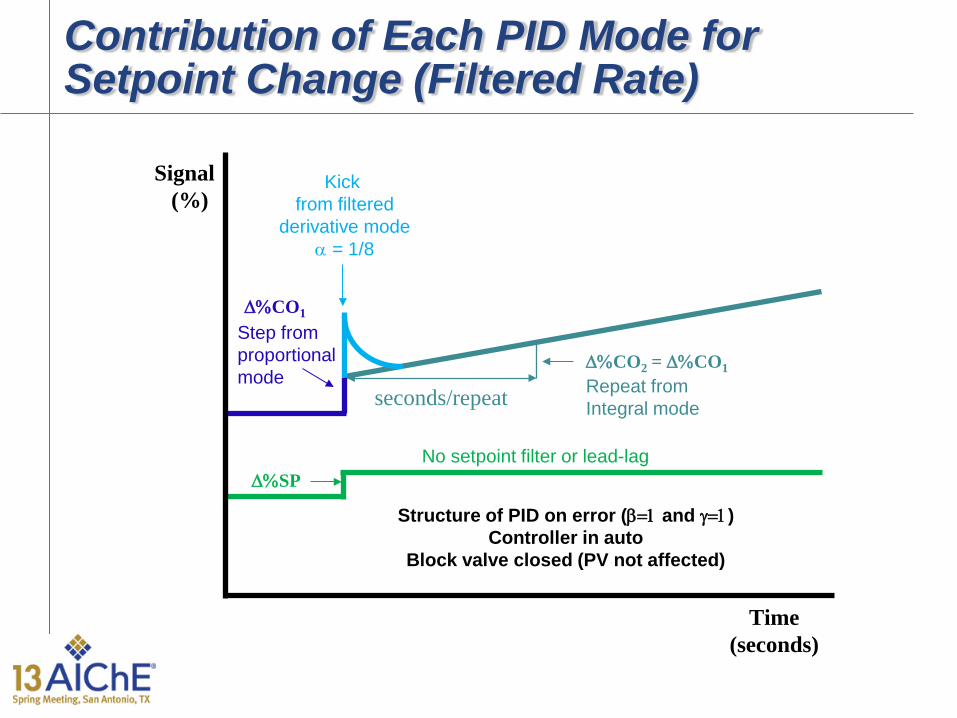
Kick from filtered
derivative mode α = 1/8
∆%CO2 = ∆%CO1
∆%SP
∆%CO1
Time (seconds)
Signal (%)
Step from proportional mode Repeat from
Integral mode
No setpoint filter or lead-lag
seconds/repeat
Contribution of Each PID Mode for Setpoint Change (Filtered Rate)
Structure of PID on error (β=1 and γ=1) Controller in auto
Block valve closed (PV not affected)

Contribution of Each PID Mode for Setpoint Change (Unfiltered Rate)
Structure of PID on error (β=1 and γ=1) Controller in auto
Block valve closed (PV not affected)
Spike from unfiltered
derivative mode α = 0
∆%CO2 = ∆%CO1
∆%SP
∆%CO1
Time (seconds)
Signal (%)
Step from proportional mode Repeat from
Integral mode
No setpoint filter or lead-lag
seconds/repeat
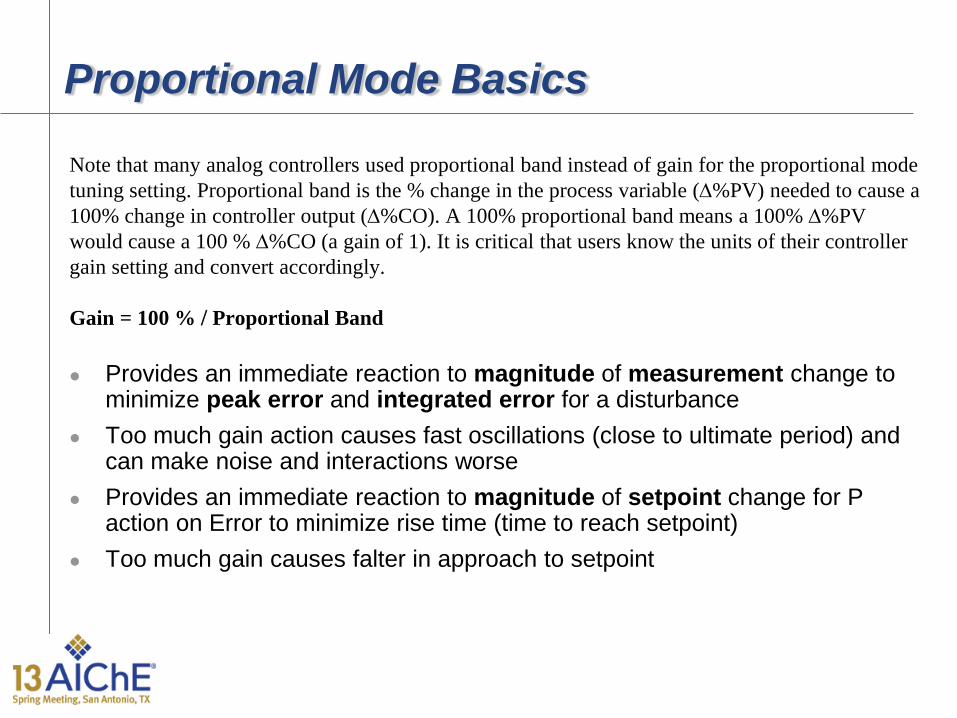
Proportional Mode Basics
Note that many analog controllers used proportional band instead of gain for the proportional mode tuning setting. Proportional band is the % change in the process variable (∆%PV) needed to cause a 100% change in controller output (∆%CO). A 100% proportional band means a 100% ∆%PV would cause a 100 % ∆%CO (a gain of 1). It is critical that users know the units of their controller gain setting and convert accordingly. Gain = 100 % / Proportional Band Provides an immediate reaction to magnitude of measurement change to
minimize peak error and integrated error for a disturbance Too much gain action causes fast oscillations (close to ultimate period) and
can make noise and interactions worse Provides an immediate reaction to magnitude of setpoint change for P
action on Error to minimize rise time (time to reach setpoint) Too much gain causes falter in approach to setpoint

Integral Mode Basics
Note that many analog controllers used reset settings in repeats per minute instead of reset time for the integral mode tuning setting. Repeats per minute indicate the number of repeats of the proportional mode contribution in a minute. Today’s reset time settings are minutes per repeat or seconds per repeat which gives the time to repeat the proportional mode contribution. Often the “per repeat” term is dropped giving a reset time setting in minutes or seconds. The smooth gradual response looking only at error is in tune with operator. Seconds per repeat = 60 / repeats per minute
Provides a ramping reaction to error (SP-PV) to eliminate offset and minimize
integrated error if stable (since error is hardly ever exactly zero, integral action is always ramping the controller output)
Too much integral action causes slow oscillations (slower than ultimate period) Too much integral action causes an overshoot (no sense of direction)

Derivative Mode Basics
Nearly all derivative tuning settings are given as a rate time in seconds or minutes. The ISA Standard Form rate time setting must never be greater than the reset time setting. The advantages and disadvantages of the derivative mode in terms of an abrupt response and amplification of noise are similar to that of the proportional mode except the relative advantages are less and the relative disadvantages are greater for the derivative mode. Derivative mode is best used to cancel out the effect of a secondary time constant. Seconds = 60 ∗ minutes
Provides an immediate reaction to rate of change of measurement change
to minimize peak error and integrated error for a disturbance Too much rate action causes fast oscillations (faster than ultimate period)
and can make noise and interactions worse Provides an immediate reaction to rate of change of setpoint change for D
action on Error to minimize rise time (time to reach setpoint) Too much rate causes fast oscillation

Proportional Only (P only) Response to Step Load Disturbance
Purple PV = 0.5 x Normal Gain Green PV = 1.0 x Normal Gain Red PV = 1.5 x Normal Gain
Brown PV = 2.0 x Normal Gain Period = 40 sec
Ultimate Period = 40 sec

Proportional + Integral (PI) Response to Step Load Disturbance
Purple PV = 1.5 x Normal Reset Green PV = 1.0 x Normal Reset Red PV = 0.75 x Normal Reset Brown PV = 0.5 x Normal Reset
Period = 65 sec
Ultimate Period = 40 sec

Proportional + Integral + Derivative (PID) Response to Step Load Disturbance
Purple PV = 0.5 x Normal Rate Green PV = 1.0 x Normal Rate Red PV = 2.0 x Normal Rate
Brown PV = 2.5 x Normal Rate Period = 25 sec
Ultimate Period = 40 sec

Self-Regulating Process
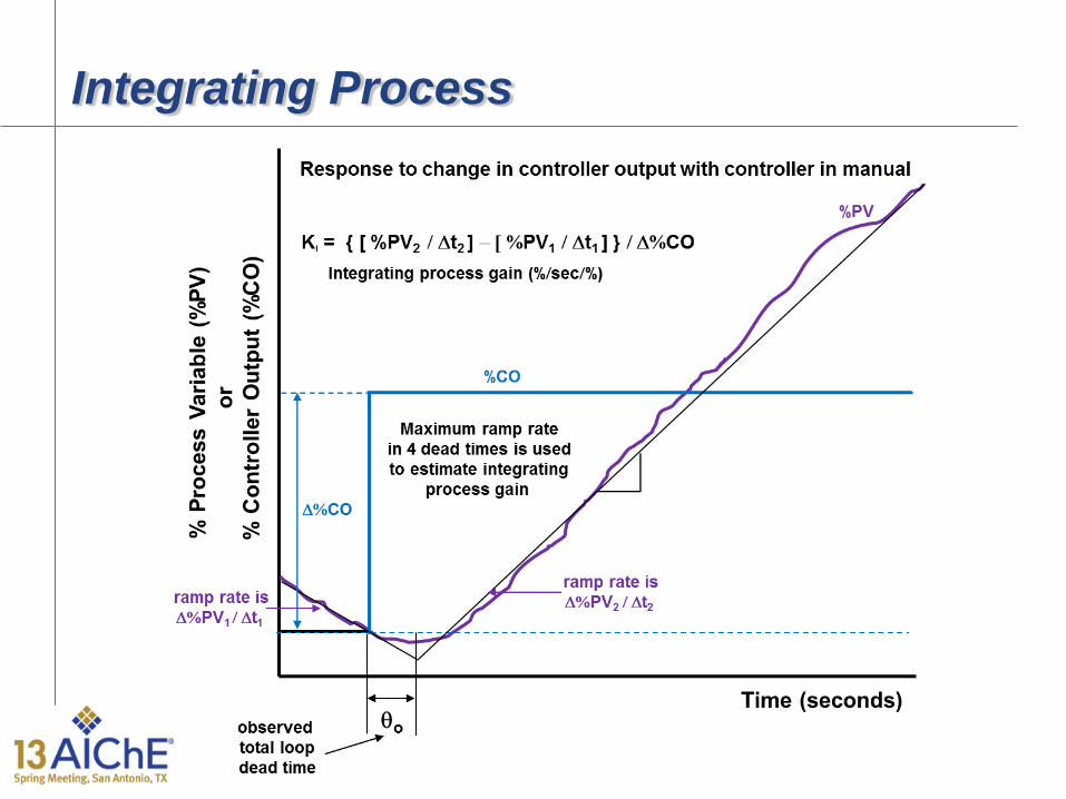
Integrating Process
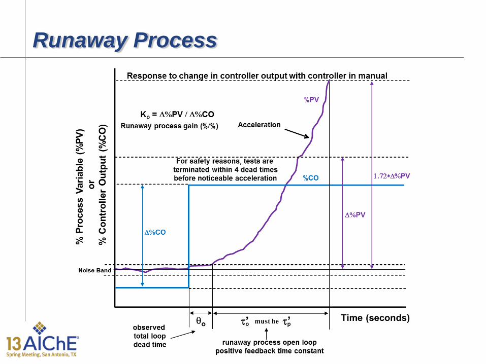
Runaway Process

Origin of Loop Dynamics

Ultimate Limit for Disturbance Rejection
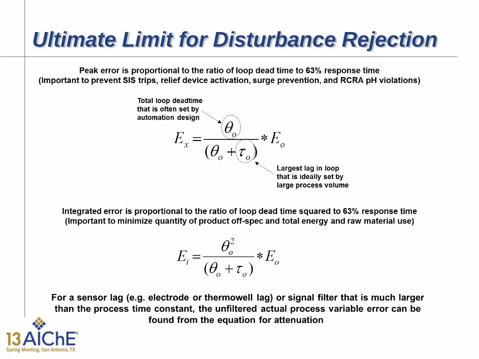
Ultimate Limit for Disturbance Rejection

Practical Limit for Disturbance Rejection

External Reset (Dynamic Reset Limit)
Prevents PID output changing faster than a valve, VFD, or secondary loop can respond – Secondary PID slow tuning – Secondary PID SP Filter Time – Secondary PID SP Rate Limit – AO, DVC, VFD SP Rate Limit – Slow Valve or VFD – Use PV for BKCAL_OUT – Position used as PV if valve is very slow and readback is fast – Enables Enhanced PID for Wireless
Stops Limit cycles from deadband, backlash, stiction, and threshold sensitivity or resolution limits
Key enabling feature that simplifies tuning and creates more advanced opportunities for PID control
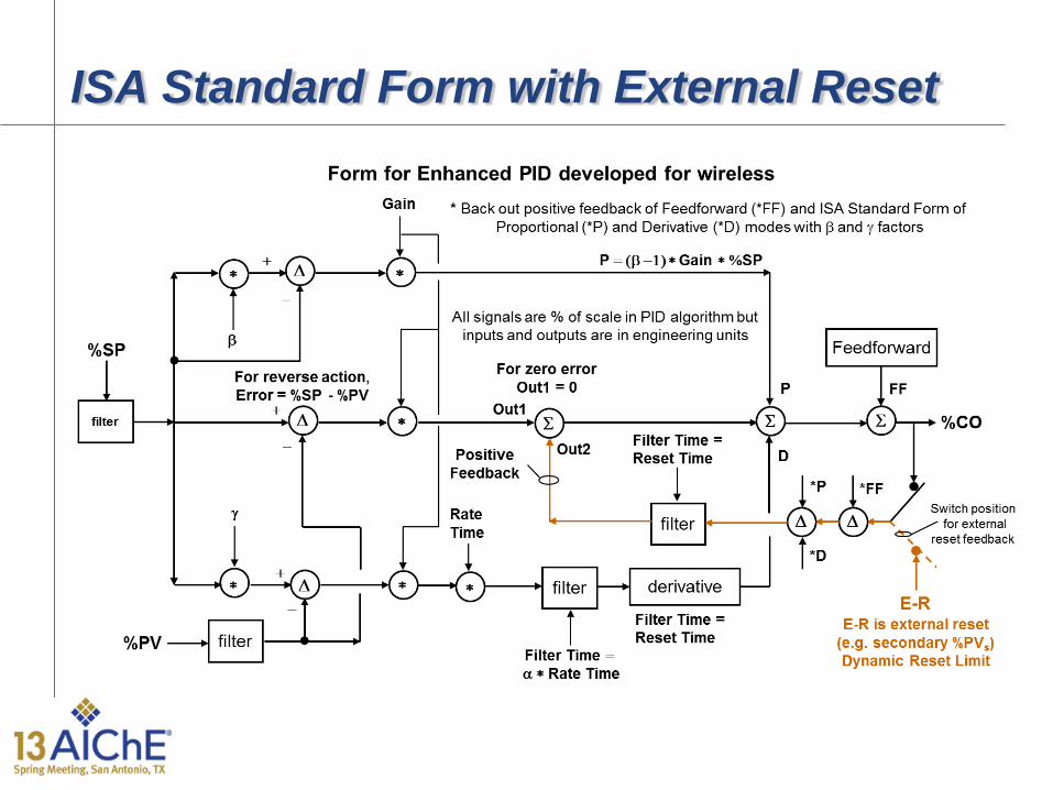
ISA Standard Form with External Reset

PID Structure Options
(1) PID action on error (β = 1 and γ = 1) (2) PI action on error, D action on PV (β = 1 and γ = 0) (3) I action on error, PD action on PV (β = 0 and γ = 0) (4) PD action on error, no I action (β = 1 and γ = 1) (5) P action on error, D action on PV, no I action (β = 1 and γ = 0) (6) ID action on error, no P action (γ = 1) (7) I action on error, D action on PV, no P action (γ = 0) (8) Two degrees of freedom controller (β and γ adjustable 0 to 1)

PID Options Effect on Setpoint Response
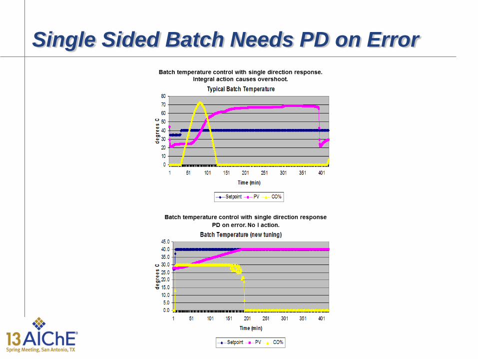
Single Sided Batch Needs PD on Error

Setpoint Rate Limits and Lead-Lag (Triple Cascade Loop)

Setpoint Filter and Lead-Lag • PID SP filter reduces overshoot enabling tuning for load disturbances
– Setpoint filter time set equal reset time • PID SP filter coordinates timing of flow ratio control
– Simultaneous changes in feeds for blending and reactions – Consistent closed loop response for model predictive control
• PID SP filter sets closed loop time constant • PID SP filter in secondary loop slows down cascade control system
rejection of primary loop disturbances – Secondary loop should be > 4x faster than primary loop
• Primary PID must have dynamic reset limit enabled • Setpoint Lead-Lag minimizes overshoot and rise time
– Lag time = reset time – Lead time = 25% lag time

Setpoint Rate Limits • AO & PID SP rate limits minimize disruption while protecting
equipment and optimizing processes – Offers directional moves suppression – Enables fast opening and slow closing surge valve – VPC fast recovery for upset and slow approach to optimum
• AO SP rate limits minimize interaction between loops – Less important loops are made 10x slower than critical loops
• PID driving AO SP or secondary PID SP rate limit must have dynamic reset limit enabled so no retuning is needed
• PID faceplate should display PV of AO to show rate limiting
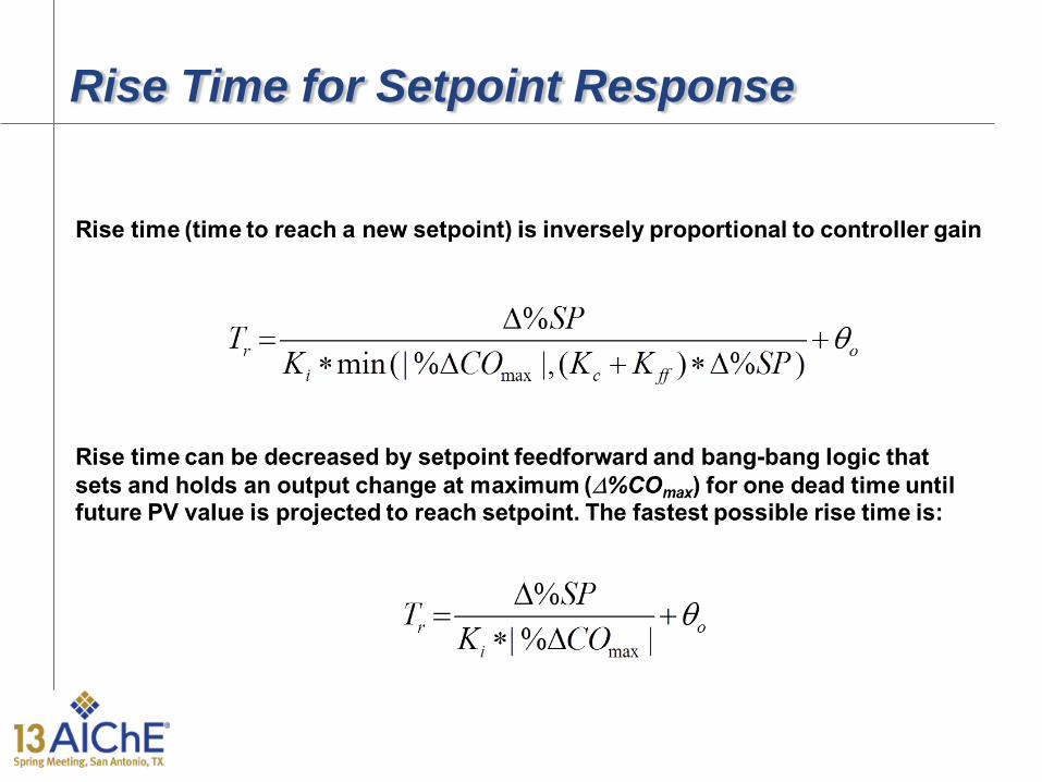
Rise Time for Setpoint Response

Output Tracking Opportunities • “Bang-Bang” logic for startup & batch SP changes:
– For SP change PID tracks output limit until the predicted PV one dead time into future gets close to setpoint, the output is then set at best/last startup or batch value for one dead time
– Works best on slow batch and integrating processes • “Open Loop Backup” to prevent compressor surge:
– When compressor flow drops below surge SP or a precipitous drop occurs in flow, PID tracks an output that provides a flow large enough to compensate for the loss in downstream flow for a time larger than the loop dead time plus the surge period.
• “Open Loop Backup” to prevent RCRA violation: – When an inline pH system PV approaches the RCRA pH limit
the PID tracks an incremental output (e.g. 0.25% per sec) opening the reagent valve until the pH sufficiently backs away

Enhanced PID for Wireless • Positive feedback implementation of reset with external-reset
feedback (dynamic reset limit) • Immediate response to a setpoint change or feedforward signal or
mode change • Suspension of integral action until change in PV • Integral action is the exponential response of the positive feedback
filter to the change in controller output in elapsed time (the time interval since last update)
• Derivative action is the PV or error change divided by elapsed time rather than PID execution
• Threshold sensitivity limit is used to prevent update from noise
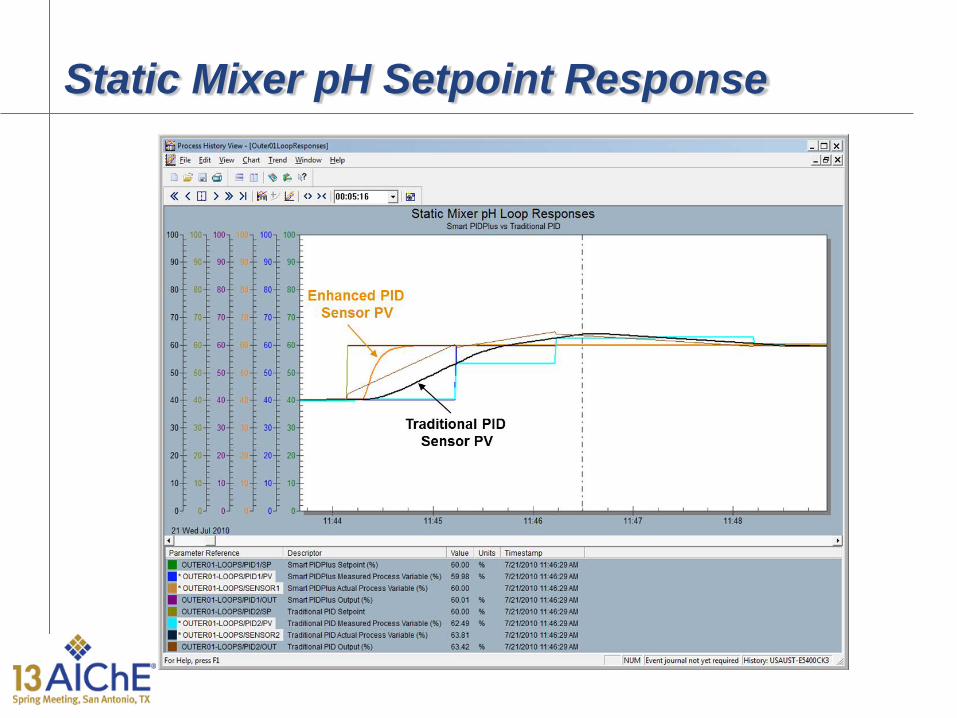
Static Mixer pH Setpoint Response

Static Mixer pH Load Response

Static Mixer pH Failure Response

Optimization of Batch Reactor by Valve Position Control (VPC)

Optimization Examples by Valve Position Control (VPC)
Optimization VPC PID PV VPC PID SP VPC PID Out Minimize Prime Mover Energy
Reactor Feed Flow PID Output
Maximum Throttle Position
Compressor or Pump Pressure SP
Minimize Boiler Fuel Cost
Steam Flow PID Output Maximum Throttle Position
Boiler Pressure SP
Minimize Boiler Fuel Cost
Equipment Temperature PID Output
Maximum Throttle Position
Boiler Pressure SP
Minimize Chiller or CTW Energy
Equipment Temperature PID Output
Maximum Throttle Position
Chiller or CTW Temperature SP
Minimize Purchased Reagent or Fuel Cost
Purchased Reagent or Fuel Flow PID Output
Minimum Throttle Position
Waste Reagent Or Fuel Flow SP
Minimize Total Reagent Use
Final Neutralization Stage pH PID Output
Minimum Throttle Position
First Neutralization Stage pH PID SP
Maximize Reactor Production Rate
Reactor or Condenser Temperature PID Output
Maximum Throttle Position
Feed Flow or Reaction Temperature SP
Maximize Reactor Production Rate
Reactor Vent Pressure PID Output
Maximum Throttle Position
Feed Flow or Reaction Temperature SP
Maximize Column Production Rate
Reboiler or Condenser Flow PID Output
Maximum Throttle Position
Feed Flow or Column Pressure SP

PID Features for Valve Position Control
PID Feature Function Advantage 1 Advantage 2
Directional Velocity Limits
Limit VPC Action Speed Based on Direction
Prevent Running Out of Valve
Minimize Disruption to Process
Dynamic Reset Limit
Limit VPC Action Speed to Process Response
Directional Velocity Limits
Prevent Burst of Oscillations
Adaptive Tuning Automatically Identify and Schedule Tuning
Eliminate Manual Tuning
Compensation of Nonlinearity
Feedforward Preemptively Set VPC Out for Upset
Prevent Running Out of Valve
Minimize Disruption
Enhanced PID Suspend Integral Action until PV Update
Eliminate Limit Cycles from Stiction &
Backlash
Minimize Oscillations from Interaction &
Delay

Self-Regulating Process Lambda Tuning

Integrating Process Lambda Tuning

Often Misunderstood Low PID Gain Effect Lag Dominant Self-Regulating Process
Period = 400 sec Ultimate Period 40 sec

Often Misunderstood Low PID Gain Effect Integrating Process
Period = 400 sec Ultimate Period 40 sec

Often Misunderstood Low PID Gain Effect Runaway Process
Period = 400 sec Ultimate Period 40 sec

Low PID Gain and Reset Time Limit

Unified Methodology - 1 Add a flow measurement to every important process and utility
stream to enable a secondary flow loop for cascade control. – A secondary flow loop isolates pressure disturbances, and nonlinearities
of the installed characteristic of control valve and variable speed drives from the control of a higher process variable.
– Flow measurement enable flow feedforward control and the possibility of changing production rates by moving plant flows in unison per PFD.
– Flow measurements enable closing material and energy balances leading to process knowledge eliminating uncertainties from pressure flow relationships and valve backlash and stiction.
– Control valves and VSD normally have a greater rangeability than a differential head or vortex meter. When this occurs, a calculated flow based on the installed characteristic should be substituted for the measurement flow before the signal becomes too noisy or in the case of the vortex meter the signal drops out. An automatic pressure drop bias enables smooth transition from measured to calculated flow

Unified Methodology - 2 Set the output limits to keep the manipulated setpoints in the
desired operating range. For variable speed drives set the process PID low output limit so the speed cannot cause the discharge head to approach the static head in order to prevent excessive sensitivity to pressure and to prevent reverse flow. In general, set the anti-reset windup limit to match the output limit. If the output scale is engineering units, the output limits and anti-reset windup must be based on the output scale range and units.
Choose the best structure for your application. Generally the best choice is structure 2 with PI on error and D on PV. For a single direction response (e.g. batch heating or neutralization), use structure 4 or structure 5 so that there is no integral action. For a highly exothermic reaction, you might want structure 5 to help prevent a runaway from integral action.
Set the signal filter noise just large enough to keep the controller output fluctuations from exceeding the resolution limit or deadband of the final control element.

Unified Methodology - 3 For near-integrating, true integrating, and runway processes use
the lambda integrating process tuning rules. To maximize the transfer of variability from the process variable to the manipulated variable, set the lambda (arrest time) equal to the maximum possible dead time* and use the largest integrating process gain for all operating conditions in the tuning. To maximize the absorption of variability (e.g. surge tank level) use the minimum arrest time computed from paper Equations 1 through 10 for all possible operating conditions. If you decrease the PID gain, proportionally increase the PID reset time to prevent slow rolling oscillations.
For self-regulating processes with the open loop time constant less than 4 times the dead time, use the lambda self-regulating tuning rules. To maximize the transfer of variability from the process variable to the manipulated variable set the lambda (closed loop time constant) equal to the maximum possible dead time* and use the largest process gain and smallest time constant for all operating conditions in the tuning (worse case is often lowest production rate).
* Due to unknowns a more practical lambda is twice the max dead time

Unified Methodology - 4 Turn on external reset feedback. Make sure the external reset
feedback signal is correctly propagated back to the PID (e.g. BKCAL signal) especially if there are split range, signal characterizer, or signal selector blocks on the PID output.
For final control elements that are slow or that have deadband or resolution limit, use a fast readback of the valve position or variable frequency drive speed as the external reset feedback to prevent a burst of oscillations from the PID output changing faster than the final control element can respond.
For final control elements that create limit cycles from resolution limits and deadband, use a fast readback of the valve position or variable frequency drive speed to stop the limit cycles
For cascade control, use the PV of the secondary loop as the external reset feedback to prevent a burst of oscillations from violation of the cascade rule where the secondary loop must be significantly faster than the primary loop.

Unified Methodology - 5 For setpoint filters of secondary loops for coordination of flow
loops, use the PV of the secondary loop as the external reset feedback to prevent the need to retune the PID.
For setpoint rate limits use the PV of the analog output block or secondary loop as the external reset feedback to prevent the need to retune the PID. Add setpoint rate limits to minimize the interaction between loops and in valve position control and to provide directional move suppression to enable a fast getaway for abnormal conditions and a slow approach to optimum. For valve position control, use an enhanced PID developed for wireless with a threshold sensitivity limit to ignore insignificant changes in the valve position to be optimized.
Add output tracking for equipment protection and a full throttle (bang-bang control) strategy for the fastest possible time to reach setpoint on startup and for batch operations.
Use valve position control for simple and quick optimization by just a PID configuration.
Unified Methodology - 6 Add output tracking logic to momentarily track an output that
insures equipment and environmental protection. For compressor surge protection track a sufficiently large opening of the surge valves. To prevent a RCRA pH violation, track a rapidly incrementing reagent valve position to prevent an effluent excursion < 2 pH or > 12 pH.
Add feedforward control for large and fast measured disturbances. For flow feedforward, use a ratio and bias station so the operator can enter a desired flow ratio and see the actual flow ratio. Setup the PID to provide a bias correction to the manipulated flow. Add dynamic compensation (dead time and lead-lag blocks) to the feedforward so the manipulated flow arrives at the same point in the process at the same time as the measured disturbance.
For wireless devices or analyzers (discontinuous PV update delay) use an enhanced PID to eliminate the need to retune the controller to prevent oscillations. If the delay is much larger than the 63% process response time, the PID gain can be set as large as the inverse of the maximum open loop gain for self-regulating processes.