a tutorial on learning human welder's behavior: sensing
TRANSCRIPT

University of KentuckyUKnowledge
Electrical and Computer Engineering FacultyPublications Electrical and Computer Engineering
1-2014
A Tutorial on Learning Human Welder's Behavior:Sensing, Modeling, and ControlY. K. LiuUniversity of Kentucky
W. J. ZhangUniversity of Kentucky
Yu Ming ZhangUniversity of Kentucky, [email protected]
Right click to open a feedback form in a new tab to let us know how this document benefits you.
Follow this and additional works at: https://uknowledge.uky.edu/ece_facpub
Part of the Electrical and Computer Engineering Commons
This Article is brought to you for free and open access by the Electrical and Computer Engineering at UKnowledge. It has been accepted for inclusionin Electrical and Computer Engineering Faculty Publications by an authorized administrator of UKnowledge. For more information, please [email protected].
Repository CitationLiu, Y. K.; Zhang, W. J.; and Zhang, Yu Ming, "A Tutorial on Learning Human Welder's Behavior: Sensing, Modeling, and Control"(2014). Electrical and Computer Engineering Faculty Publications. 1.https://uknowledge.uky.edu/ece_facpub/1

A Tutorial on Learning Human Welder's Behavior: Sensing, Modeling, and Control
Notes/Citation InformationPublished in Journal of Manufacturing Processes, v. 16, issue 1, p. 123-136.
Per the publisher Elsevier: "NOTICE: this is the author’s version of a work that was accepted for publicationin Journal of Manufacturing Processes. Changes resulting from the publishing process, such as peer review,editing, corrections, structural formatting, and other quality control mechanisms may not be reflected in thisdocument. Changes may have been made to this work since it was submitted for publication. A definitiveversion was subsequently published in Journal of Manufacturing Processes, v. 16, issue 1, ( January 2014). DOI:http://dx.doi.org/10.1016/j.jmapro.2013.09.004"
Digital Object Identifier (DOI)http://dx.doi.org/10.1016/j.jmapro.2013.09.004
This article is available at UKnowledge: https://uknowledge.uky.edu/ece_facpub/1

1
A Tutorial on Learning Human Welder's Behavior: Sensing, Modeling, and Control
Y.K. Liu, W.J. Zhang, Y.M. Zhang
Institute for Sustainable Manufacturing and Department of Electrical and Computer Engineering, University
of Kentucky, Lexington, KY, 40506
* Corresponding Author, Phone: 859-323-3262, Fax:859-257-3092, Email:[email protected]
Key Words
Human Intelligence, Weld Pool, Sensing, Modeling, Control, GTAW
Abstract
Human welder's experiences and skills are critical for producing quality welds in manual GTAW process.
Learning human welder's behavior can help develop next generation intelligent welding machines and train
welders faster. In this tutorial paper, various aspects of mechanizing the welder's intelligence are surveyed,
including sensing of the weld pool, modeling of the welder's adjustments and this model-based control
approach. Specifically, different sensing methods of the weld pool are reviewed and a novel 3D vision-based
sensing system developed at University of Kentucky is introduced. Characterization of the weld pool is
performed and human intelligent model is constructed, including an extensive survey on modeling human
dynamics and neuro-fuzzy techniques. Closed-loop control experiment results are presented to illustrate the
robustness of the model-based intelligent controller despite welding speed disturbance. A foundation is thus
established to explore the mechanism and transformation of human welder's intelligence into robotic welding
system. Finally future research directions in this field are presented.
1. Introduction
In manual Gas Tungsten Arc Welding (GTAW) process skilled welders can appraise the state of weld joint
penetration through their observation on the weld pool and intelligently adjust the welding parameters (e.g.,
current, welding speed, arc length and torch orientation) accordingly to control the weldingprocess. Because
of their versatile sensing capability and experience-based behavior in response to the information they sense,
they may be preferred over mechanized welding control systems in certain applications.
Although welders’ experience and skills are crucial in producing quality welds, human welders have
limitations. Critical welding operations require welders concentrate consistently in order to react rapidly and
accurately. Inconsistent concentration, fatigue and stress do build up such that welders’ capabilities degrade
during daily operations. Moreover, experience and skills needed for critical operations typically require years
to develop while manufacturing industry is experiencing insufficient number of skilled welders for a long
time [1]. The mechanism of welder’s experience-based behavior thus should be fully explored and utilized
to develop intelligent robotic welding systems that combine human welder's intelligence and physical
capabilities of the mechanized welding machines, which paves the foundation for next generation
manufacturing processes. Modeling human welders’ responses, i.e., how they respond to the information
they sense, thus plays a fundamental role in facilitating such a development. In addition, the resultant welder
response modelsmay also be utilized to understand why less skilled welders are not performing as well as
skilled welders and help train welders faster in order to help resolve the skilled welder shortage issue the
manufacturing industry is currently facing [2].
2
In the following subsections, fundamentals of GTAW process and analysis of human welder behavior are
presented.
1.1 GTAW Process
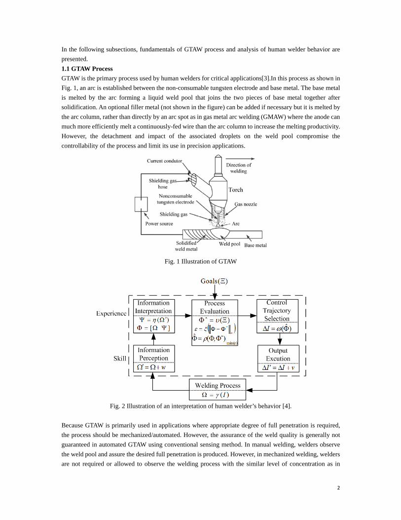
GTAW is the primary process used by human welders for critical applications[3].In this process as shown in
Fig. 1, an arc is established between the non-consumable tungsten electrode and base metal. The base metal
is melted by the arc forming a liquid weld pool that joins the two pieces of base metal together after
solidification. An optional filler metal (not shown in the figure) can be added if necessary but it is melted by
the arc column, rather than directly by an arc spot as in gas metal arc welding (GMAW) where the anode can
much more efficiently melt a continuously-fed wire than the arc column to increase the melting productivity.
However, the detachment and impact of the associated droplets on the weld pool compromise the
controllability of the process and limit its use in precision applications.
Fig. 1 Illustration of GTAW
Fig. 2 Illustration of an interpretation of human welder’s behavior [4].
Because GTAW is primarily used in applications where appropriate degree of full penetration is required,
the process should be mechanized/automated. However, the assurance of the weld quality is generally not
guaranteed in automated GTAW using conventional sensing method. In manual welding, welders observe
the weld pool and assure the desired full penetration is produced. However, in mechanized welding, welders
are not required or allowed to observe the welding process with the similar level of concentration as in

3
manual operation. Mechanized/automated systems rely on precision control of joint fit-up and welding
conditions and tedious programming of welding parameters to produce repeatable results. However,
precision control of joints and welding conditions is very costly and not always guaranteed. Up to date, there
are no satisfactory sensors that can conveniently/ automatically monitor the penetration depth or the degree
of the full penetration like a skilled welder. It is thus of great interest to develop the intelligent welding
machines that can sense the welding process like the human welder yet do not suffer from the limitations of
the human welder. In the following subsection the human welder's behavior is analyzed.
1.2 Human welder's behavior
The diagram of the human welder’s behavior is shown in Fig. 2 [4]. Given a certain welding task, a human
welder starts with some initial estimation input I which may include the current, arc length, welding speed,
etc. After the input of the initial control, the welder perceives necessary direct information from the weld
pool. is the information that should be sensed from the welding process which is controlled by the welding
parameters: )(I (1)
The welder may derive indirect information from the direct information: )( (2)
The instant state of welding process may contain both the direct and indirect information of welding process. The process evaluation involves the decision-making process. Given the inconsistent nature of human welder action, there may be certain inconsistency of welding performance even for a well-trained welder. The welder first maps the goals of the welding process into the desired state of welding process :
)( (3)
Then the welder evaluates the desired and the instant state similarly like with some norm-based cost function, shown in (4):
n
(4)
And the optimal state for the next instant ̂ can be considered to minimize the cost function:
)min(),(ˆ
(5)
Eventually, the welder performs a mathematic equivalence to mapping from the optimal state to the control:
)ˆ( I (6)
The output execution may be considered to be perturbed by a white Gaussian noise v , which reflects the maneuver skill of the human welder. There exists a common pattern from the direct information to the welder’s output I which is defined as the following equation:
)( FI (7)
The model of human welder’s behavior (7) can be considered as the combination of the five elements from
“Information perception” to “Output execution” in Fig. 2. It is possibly nonlinear and time-varying.
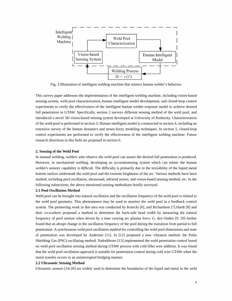
As has been discussed above, human welder has limitations such as inconsistent concentration, fatigue and
stress.For the intelligent welding machine that mimics the human welder's intelligence, these limitations can
be overcome. The illustration of intelligent welding machine can be observed in Fig.3. In this figure, the
information perception block in Fig.2 is substituted with a vision-based sensing system. The output of the
sensing system is the 3D coordinates of the weld pool surface. Like the human welder's ability to interpret
the complex weld pool shape, intelligent welding machine will characterize the weld pool, and output certain
characteristic parameters to the human intelligent model. The outputs of the human intelligent model are the
welding inputs, and will be inputted into the welding process.
4
Fig. 3 Illustration of intelligent welding machine that mimics human welder’s behavior.
This survey paper addresses the implementation of the intelligent welding machine, including vision-based
sensing system, weld pool characterization, human intelligent model development, and closed-loop control
experiments to verify the effectiveness of the intelligent human welder response model to achieve desired
full penetration in GTAW. Specifically, section 2 surveys different sensing method of the weld pool, and
introduced a novel 3D vision-based sensing system developed at University of Kentucky. Characterization
of the weld pool is performed in section 3. Human intelligent model is constructed in section 4, including an
extensive survey of the human dynamics and neuro-fuzzy modeling techniques. In section 5, closed-loop
control experiments are performed to verify the effectiveness of the intelligent welding machine. Future
research directions in this field are proposed in section 6.
2. Sensing of the Weld Pool
In manual welding, welders who observe the weld pool can assure the desired full penetration is produced.
However, in mechanized welding, developing an accuratesensing system which can mimic the human
welder's sensory capability is difficult. The difficulty is primarily due to the invisibility of the liquid metal
bottom surface underneath the weld pool and the extreme brightness of the arc. Various methods have been
studied, including pool oscillation, ultrasound, infrared sensor, and vision-based sensing method, etc. In the
following subsections, the above mentioned sensing methodsare briefly surveyed.
2.1 Pool Oscillation Method
Weld pool can be brought into natural oscillation and the oscillation frequency of the weld pool is related to
the weld pool geometry. This phenomenon may be used to monitor the weld pool in a feedback control
system. The pioneering work in this area was conducted by Kotecki [6], and Richardson [7].Hardt [8] and
their co-workers proposed a method to determine the back-side bead width by measuring the natural
frequency of pool motion when driven by a time varying arc plasma force. G. den Ouden [9, 10] further
found that an abrupt change in the oscillation frequency of the pool during the transition from partial to full
penetration. A synchronous weld pool oscillation method for controlling the weld pool dimensions and state
of penetration was developed by Andersen [11]. Ju [12] proposed a new vibration method: the Pulse
Shielding Gas (PSG) oscillating method. Yudodibroto [13] implemented the weld penetration control based
on weld pool oscillation sensing method during GTAW process with cold filler wire addition. It was found
that the weld pool oscillation approach is suitable for penetration control during cold wire GTAW when the
metal transfer occurs in an uninterrupted bridging manner.
2.2 Ultrasonic Sensing Method
Ultrasonic sensors [14-20] are widely used to determine the boundaries of the liquid and metal in the weld

5
pool.In [15] the developed ultrasonic sensing system could locate and track the welding seam ensuring
correct positioning of the welding head relatively to the joint preparation. At Georgia Institute of Technology,
Ume [16,17] developed non-contact ultrasonic penetration sensors based on laser-phased array techniques.
Recently various non-contact ultrasonic sensing methods have been developed, such as laser ultrasonic
sensing [14, 20], electromagnetic acoustic transducer (EMAT) ultrasonic sensing [15], laser-EMAT
ultrasonic sensing [19], etc. Mi[20] further developed a sensing system to monitor the weld penetration. The
sensing system was based on using a laser phased array technique to generate focused and steered ultrasound,
and an electromagnetic acoustic transducer (EMAT) as a receiver.
2.3 Infrared Sensing Method
Infrared sensing is a type of non-contact thermal measurement technique which has been widely used in
various applications. Because the temperature distribution in the weld zone contains abundant information
about the welding process, infrared sensing of welding processes has drawn attentions from various research
institutions. Chin [21-24] developed a thermal imaging system to measure the variations in weld process
parameters such as bead width, penetration depth, and torch offset. The penetration depth has been correlated
with the infrared characteristics of the infrared image. The interference of arc radiation was reduced by
selecting scanner with specific wavelength region. At MIT, Hardt used an infrared camera to view the
temperature field from the back-side [25]. The penetration depth was precisely estimated from the measured
temperature distribution and then controlled [26]. In [27] infrared sensor was used to monitor weld process
parameters including weld bead width, penetration depth, and torch position. Analysis of the computed
ellipse showed that the temperature gradient or heat energy distribution (minor axis of the ellipse) and the
heat input (volume under the temperature profiles) varied with the penetration depth.
2.4 Vision Based Method
Skilled welders can assure the desired full penetration based on their observation of the weld pool. The weld
pool should thereforecontain abundant information about the weld penetration. Vision-based systems have
been applied to monitor the weld pool emulating human welders' visual sensory ability. In the following
subsections, vision-based sensing methods are extensively reviewed, including 2D weld pool sensing, and
3D weld pool sensing methods.
2.4.1 2D Weld Pool Sensing
2D weld pool geometry contains certain information of the welding process, and has been used to monitor
the welding process and control the weld penetration [28-30]. Fan et.al [29] studied 2D visual sensing and
penetration control in aluminum (Al) alloy pulse GTAW process. In [30] two normal CCD cameras were
used to capture clear images from two directions: one of them was used to measure the root gap and another
one is used to measure the geometric parameters of the weld pool.
2.4.2 3D Weld Pool Sensing
Although 2D weld pool geometry has been obtained with above different techniques, the
convexity/deformation of the weld pool is not yet fully explored. Early researchers have found that important
information such as weld defects and penetration are contained in the surface deformation of the weld pool
[31, 32]. Compared with the 2D weld pool geometry, the 3D geometry can better predict the weld penetration
which is measured by the backside weld bead width [33]. Numerous methods have been developed to
reconstruct the 3D weld pool surface.
The measurement of general 3D surface has been recently studied extensively with techniques which can be
roughly categorized into three branches: 1) reflectometry / deflectometry with fringe reflection technique
[34-36]; 2) phase shifted digital fringe projection technique for diffuse objects [37, 38]; 3) shape from
shading technique [39]. Unfortunately, the dynamic and specular nature of the weld pool and the interference

6
from the strong arc radiation complicate the observation and deteriorate the effectiveness of most of those
methods.
Specifically for the 3D weld pool measurement, the most popular techniques currently being studied can be
divided into four categories:
Model-based reconstruction
The 3D weld pool surface was partially reconstructed based on a simple model proposed in [40]. The
reconstruction algorithm was further applied in [41] for the control of weld pool shape. A fuzzy logic
controller was constructed to control weld penetration. Although the model-based reconstruction
algorithm is simple and fast, it can only measure the height of the weld bead that is solidifying or have
already solidified at the rear of the weld pool. The 3D geometry of head of the weld pool cannot be
acquired using this method.
Stereovision measurement
In [42], two cameras were synchronized to capture the two images of weld pool surface simultaneously
in the short circuit period during the Surface Tension Transfer (STT) process and external illumination
was used. The paired images were rectified using calibration parameters obtained through the stereo
calibration procedure. Then by using stereo image processing algorithms the weld pool shape was
rendered in 3D. A closed-loop control system was further developed using the technique for robot
welding process [43]. However, the shape of the bright part in the head of the weld pool cannot be
acquired by using this method. Further, the accurate reconstruction of the weld pool requires both
precise synchronization of the two cameras and high quality of the captured images.
To avoid the synchronization problem, the biprism stereo vision sensing was proposed in which one
camera was used with a biprism attached on its head [44]. However, only the height of the weld pool
boundary was extracted in real-time, the 3D geometry inside the weld pool was missed. A similar
reconstruction algorithm has been utilized in a stereo sensing system using single camera with a stereo
adapter developed to reconstruct the 3D weld pool for tracking particle flow on the weld pool surface
[45].
Shape from shading reconstruction
3D weld pool reconstruction algorithms have also been proposed based on shape from shading method
[46-50]. Zhao et al. [49] used this algorithm to reconstruct the surface from one single weld pool image.
The extracted three-dimensional parameters for the weld pool surface were verified and used for
double-sided shape control. However, the algorithms are usually complex and thus used for off-line
reconstruction of the 3D weld pool surface. Furthermore, the reconstruction algorithms using shape
from shading are based on two assumptions: 1) The object surface is a Lambertian surface which
reflects light with equal intensity in all directions; 2) The camera and the light source are at the infinite
far distance from the object surface, while the weld pool is a specular surface which is not a Lambertian
surface. The camera and light source in the experiment systems are not far enough from the weld pool
such that the infinite far position assumption is invalid. Therefore, the 3D weld pool reconstruction
using shape from shading might not be an ideal solution.
Structured-light based sensing
A structured-light vision system was developed in [51] projecting a pulsed laser on the weld pool
surface through a special grid. A high shutter-speed camera was used to capture the laser stripe pattern
reflected by the weld pool surface. However, the synchronization of the laser and high-speed shutter
required specific, high-costly, and sophisticated equipment. The boundary of the weld pool is also hard
to extract using this sensing method.Follow-up study [52] provided a measurement system based on a
7
mathematical model of weld pool surface. Although this work did not propose a new reconstruction
algorithm, it provided some novel insights of 3D weld pool surface measurement.A laser grating
sensing technique was proposed in [53]. The reflected grating was captured by a two-lens system. The
depth of weld pool was determined based on the phase changes of the deformed grating image [54].
However, using this method the boundary of the weld pool was hard to be determined. A novel
reconstruction algorithm using the slope field and point tracking of the dot matrix has been proposed in
[55]. A laser pattern reflected from the weld pool surface has been intercepted/imaged by/on a diffusive
imaging plane placed with a distance from the weld pool [56]. The camera aims at the imaging plane
(rather than the weld pool illuminated by the extremely strong arc) to acquire the reflected laser pattern.
Its uniqueness lied in its simultaneous use of the distance and specular nature of the weld pool surface
to significantly decay the arc radiation but not the intensity of the laser reflection from the specular
weld pool surface despite the distance. However, this slope error based algorithm requires numerous
iterative loops till the estimated surface approaches the actual weld pool surface resulting in relatively
large reconstruction errors. Similarly, this imaging method and reconstruction algorithm have been used
to image and reconstruct the weld pool surface in gas metal arc welding (GMAW) using a five line laser
pattern [57].
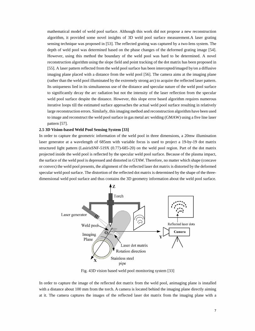
2.5 3D Vision-based Weld Pool Sensing System [33]
In order to capture the geometric information of the weld pool in three dimensions, a 20mw illumination
laser generator at a wavelength of 685nm with variable focus is used to project a 19-by-19 dot matrix
structured light pattern (LasirisSNF-519X (0.77)-685-20) on the weld pool region. Part of the dot matrix
projected inside the weld pool is reflected by the specular weld pool surface. Because of the plasma impact,
the surface of the weld pool is depressed and distorted in GTAW. Therefore, no matter which shape (concave
or convex) the weld pool presents, the alignment of the reflected laser dot matrix is distorted by the deformed
specular weld pool surface. The distortion of the reflected dot matrix is determined by the shape of the three-
dimensional weld pool surface and thus contains the 3D geometry information about the weld pool surface.
Fig. 43D vision based weld pool monitoring system [33]
In order to capture the image of the reflected dot matrix from the weld pool, animaging plane is installed
with a distance about 100 mm from the torch. A camera is located behind the imaging plane directly aiming
at it. The camera captures the images of the reflected laser dot matrix from the imaging plane with a
8
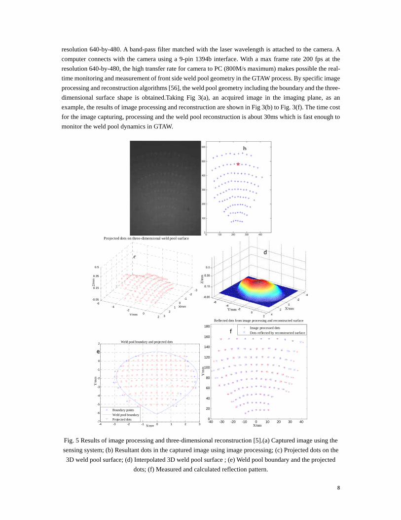
resolution 640-by-480. A band-pass filter matched with the laser wavelength is attached to the camera. A
computer connects with the camera using a 9-pin 1394b interface. With a max frame rate 200 fps at the
resolution 640-by-480, the high transfer rate for camera to PC (800M/s maximum) makes possible the real-
time monitoring and measurement of front side weld pool geometry in the GTAW process. By specific image
processing and reconstruction algorithms [56], the weld pool geometry including the boundary and the three-
dimensional surface shape is obtained.Taking Fig 3(a), an acquired image in the imaging plane, as an
example, the results of image processing and reconstruction are shown in Fig 3(b) to Fig. 3(f). The time cost
for the image capturing, processing and the weld pool reconstruction is about 30ms which is fast enough to
monitor the weld pool dynamics in GTAW.
Fig. 5 Results of image processing and three-dimensional reconstruction [5].(a) Captured image using the
sensing system; (b) Resultant dots in the captured image using image processing; (c) Projected dots on the
3D weld pool surface; (d) Interpolated 3D weld pool surface ; (e) Weld pool boundary and the projected
dots; (f) Measured and calculated reflection pattern.
-3-2
-1
0
1
2
3
-6-4
-20
2
-0.05
0.15
0.35
0.5
X/mm
Projected dots on three-dimensional weld pool surface
Y/mm
Z/m
m
-4 -3 -2 -1 0 1 2 3-7
-6
-5
-4
-3
-2
-1
0
1
2
X/mm
Weld pool boundary and projected dots
Y/m
m
Boundary points
Weld pool boundaryProjected dots
-40 -30 -20 -10 0 10 20 30 400
20
40
60
80
100
120
140
160
180
X/mm
Y/m
m
Reflected dots from image processing and reconstructed surface
Image processed dots
Dots reflected by reconstructed surface
dc
e
f
a b
9
3. Characterization of the Weld Pool
The ability to directly monitor the weld pool surface detailed in previous subsection represents a major
progress toward next generation intelligent welding because the weld pool surface should contain sufficient
information to determine the weld joint penetration as skilled human welders can. However, for a machine
to be able to use the weld pool surface to determine the weld joint penetration, characteristic parameters
should be used rather than the large set of 3D coordinates. These characteristic parameters should keep the
fundamental information in the weld pool surface about the weld joint penetration.
In order to obtain the optimal characteristic parameters, various experiments under different welding
conditions have been performed to produce full penetration welds with different back-side bead widths and
acquire corresponding images used to reconstruct the weld pool surface and calculate candidate characteristic
parameters [33]. The experiments have been designed to produce acceptable distributions for the candidate
characteristic parameters in order to ensure the validity of the resultantmodels. Five candidate characteristic
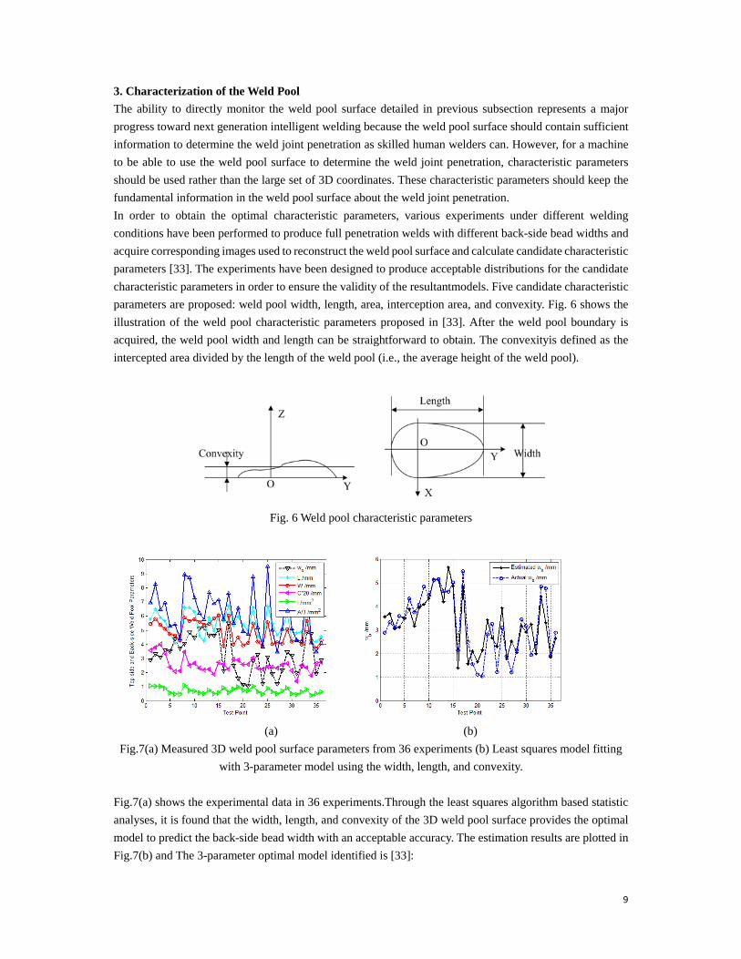
parameters are proposed: weld pool width, length, area, interception area, and convexity. Fig. 6 shows the
illustration of the weld pool characteristic parameters proposed in [33]. After the weld pool boundary is
acquired, the weld pool width and length can be straightforward to obtain. The convexityis defined as the
intercepted area divided by the length of the weld pool (i.e., the average height of the weld pool).
Fig. 6 Weld pool characteristic parameters
(a) (b)
Fig.7(a) Measured 3D weld pool surface parameters from 36 experiments (b) Least squares model fitting
with 3-parameter model using the width, length, and convexity.
Fig.7(a) shows the experimental data in 36 experiments.Through the least squares algorithm based statistic
analyses, it is found that the width, length, and convexity of the 3D weld pool surface provides the optimal
model to predict the back-side bead width with an acceptable accuracy. The estimation results are plotted in
Fig.7(b) and The 3-parameter optimal model identified is [33]:

10
1.7906 0.5657 10.8057 0.9868bw W L C (8)
Using these characteristic parameters, the back-side bead width can be determined using the parametric
model (8) with an acceptable accuracy. The parametric model (8) and characteristic parameters thus
adequately extracted the information contained in the large set of 3D coordinates for the sample points on
the 3D weld pool surface and made it possible to use the weld pool surface to determine and control the weld
joint penetration and emulate the intelligence of a skilled welder.
4. Modeling of the human welder
In this section modeling of the human welder is presented, including an extensive survey of the human
dynamics and neuro-fuzzy modeling techniques.
4.1 Human response modeling
Despite the trend of growing automation degree in industrial processes and machines, the human
operator/controller is still irreplaceable in various applications. What makes the identification of human
operators’ behavior such as a challenging endeavor is that the human operator is a nonlinear, often time-
varying controller whose coefficients might vary rapidly with factors such as motivation, workload, fatigue,
and other physiological variations [65, 68]. Specifically in welding operations, a welder makes decisions
primarily based on past learned experiences/skills which might not involve a fundamental understanding of
the laws of welding physics. Also, a human welder assesses and controls a welding process using a
humanistic approach where the feedback sensory information acquired by the welder might be imprecise
and only reflects partial truths about the instant status of the weld process.
Modeling and identifying the dynamics of a human controller/operator originated from the theories of
servomechanism and filtering in the 1940’s. The research made great strides in the late 1960’s and 1970’s.
A series of preliminary experiments were conducted on human tracking in one-dimensional compensatory
task [58]. McRuer and Jex conducted a systematic measurement of the human operator with a variety of
controlled system dynamics and random-appearing inputs of different bandwidths [59, 60]. A crossover
model of human operator was proposed that can describe the linear portion of the human operation in a
single-loop compensatory task in a frequency range around crossover frequency.
Optimal control theory was then introduced in human operator behavior identification [61]. It was based on
an assumption that the well-trained human operator behaves in a nearly optimal manner subject to the
inherent physio-physical limitations. Based on the assumption, an optimal control model (OCM) was
proposed in 1970 on the dynamic characteristics of a pilot[62].The transfer function was considered as the
cascaded of the inherent part of reaction time delays and lags attributed to the neuromuscular system and the
equalization part adjustable to the task requirement, where the time delay comes from the various internal
time delays associated with visual, center processing, and neuro-motor pathways.
The OCM was later extended by Tomizuka to cover preview tracking [63, 64]. In addition, a modified
optimal control model (MOCM) was proposed by Davidson and Schmit in 1992 [71]. The MOCM replaced
the time delay of the OCM with a Pade approximation that allowed one to obtain a soletransfer function
representation of the operator. Many researchers have continuously studied the tracking ability and
characteristics of the human operator as an adaptive controller [65], a tele-manipulator[66] or an optimal
controller [67]. Unfortunately, these methods lead to typically high order for the obtained models. For
instance, the order of these OCM-based models is equal to the sum of the orders of the controlled element,
disturbance filter, neuro-motor lag and Pade delay. This feature makes insight into the operator control model
difficult to determine. A fixed-order optimal control model based on MOCM was thus proposed to reduce

11
the order while keeping the model optimality [72]. Nonlinear methods such as neural networks, neuro-fuzzy
or adaptive models were employed as well to model the human actions [77-81].
The modeling of the human operator has been studied in the physiological perspective. Based on [73, 75],
in the learning stage the cerebral cortex is playing the role of controller in the feedback path. In [74], the
feedback error learning model was proposed. The model considered that the human hand/thumb motion skill
comes from the feed-forward structure of the cerebellum representing the inverse model of the hand/thumb
system. In addition, an iterative manual control model has been proposed based on human operator’s
physiological perspective [70]. A recalling factor has been introduced in the model representing the human
operator’s experiences/skills. The model indicates that human operators tune their control actions using error
and error rate in each iteration.
A human operator intermittently scans the state of the controlled system and continuously operates. A skillful
operation means that the information is scanned less frequently. A control action similar to the minimum
attention [82] might be found in human operation. In addition to such minimum attention, Ito’s observation
in that if the operation skill level exceeds to a certain extent, the operation becomes of feed-forward type,
can be interpreted as that the interval of the attention becomes longer as the skill becomes better. Therefore,
for a skilled operator, the control action would tend to be feed-forward type, while an unskilled operator
controls the system in a feedback close loop. Also, the observation of the system state might be achieved by
the trigger of the special occasion of the event [83].
The delay in the human operation should be one of the important factors to study the stability of the human
in the close-loop control system. Time-varying delay time of a human controller is studied in [69] in manual
tracking tasks. A discrete time recursive delay identifier is proposed to estimate the fractional delay time by
embedding the bilinear interpolation scheme in the extended Kalman filter. Yet, Kleinman [61, 62] stated
that the delay from the visual perception to the neuro-motor pathway was not necessarily considered in
human operation since a skilled human operator predicts that state. In addition, it is considered in [76] that
the cerebellum has the function of the Simith Predictor which compensates the delay in the closed loop.
Although the nonlinear methods typically improve the prediction performance to some extent, it is still very
appealing to use linear/hybrid models due to their convenience for analysis and design [84, 88, 89]. A new
hybrid fuzzy-ARX modeling method has been developed for predicting the human operator control actions
in [85]. A linear dynamic model was proposed based on stochastic switched dynamics in [86]. The
motivation of the modeling is the observation that the operator appropriately switches some simple primitive
skills which might be caused by human’s decision making [87].
4.2Neuro-fuzzy Modeling
This subsection introduces the basic definitions and concepts for neuro-network, fuzzy set, as well as neuro-
fuzzy modeling technique.
Neural networks (NNs) approach has been widely used for regression, identification, system modeling and
control applications in high-dimensional systems. Specifically, adaptive network is considered to be the
unifying framework that subsumes almost all neural network paradigms with supervised learning capabilities
[91]. It is a network structure consisting of nodes through links. Each node represents a process unit, and the
links represents the causal relationship between the nodes. Parameters of the nodes / links are modifiable,
making the network adaptive. The basic learning rule of the adaptive networks is steepest descent method
[100]. Rumelhart et al. [101] utilized the method, also well known as "backpropagation learning rule", to
find the gradient in a multilayer neural network.
Classical set is referred to a set with a crisp and unambiguous boundary. Although it is suitable for various
applications, they do not reflect the natural abstract and imprecise human thoughts. A fuzzy set, is a set
12
without a crisp boundary. It describes the transition from “belonging to a set” to “not belonging to a set” as
a gradual and smooth membership functions, which gives fuzzy sets flexibility in modeling commonly used
linguistic expressions [90].
Fuzzy inference system (FIS) is a computing framework based on fuzzy set theory, fuzzy if-then rules, and
fuzzy reasoning [91]. It is also referred to as fuzzy-rule-based system [91], fuzzy expert system [92], fuzzy
model [93, 94], fuzzy associative memory [95], fuzzy logic controller [96, 97, 98], and fuzzy systems. The
basic structure of a FIS consists of three components: a rule base (a selection of fuzzy rules), a database
(membership functions used in the fuzzy rules), as well as a reasoning mechanism (performs fuzzy reasoning
based on the rules and derive a conclusion). There are several types of FIS, including Mamdani fuzzy
inference system [98], Sugeno fuzzy model (or TSK fuzzy model) [93, 94], and Tsukamoto fuzzy models
[99]. The differences between these FIS lie in the consequents of fuzzy rules, aggregation and defuzzification
procedures.
In traditional fuzzy systems, membership functions are pre-determined by domain experts [102]. In these
models, however, no systematic adjustments are made on the fuzzy rules, membership functions, or
reasoning mechanism based on the behavior of the fuzzy system. Such fuzzy rules could be vague,
misinterpreted, or incomplete, which may severely deteriorate the performance of the fuzzy systems.
Therefore, it is tempting to apply optimization techniques to tune the parameterized membership functions
for better fuzzy model performance.
Neuro-fuzzy approach (i.e. the fusion of the NNs and fuzzy logic) determines the parameters in fuzzy models
using learning techniques developed in neural networks, and has been successfully applied in various areas
[103-106]. Jang [107, 108] developed the Adaptive Neuro-Fuzzy Inference System (ANFIS) by using a
hybrid learning procedure. Recently, ANFIS has been employed to model nonlinear functions, identify
nonlinear components in control systems, and predict chaotic time series [109-111].
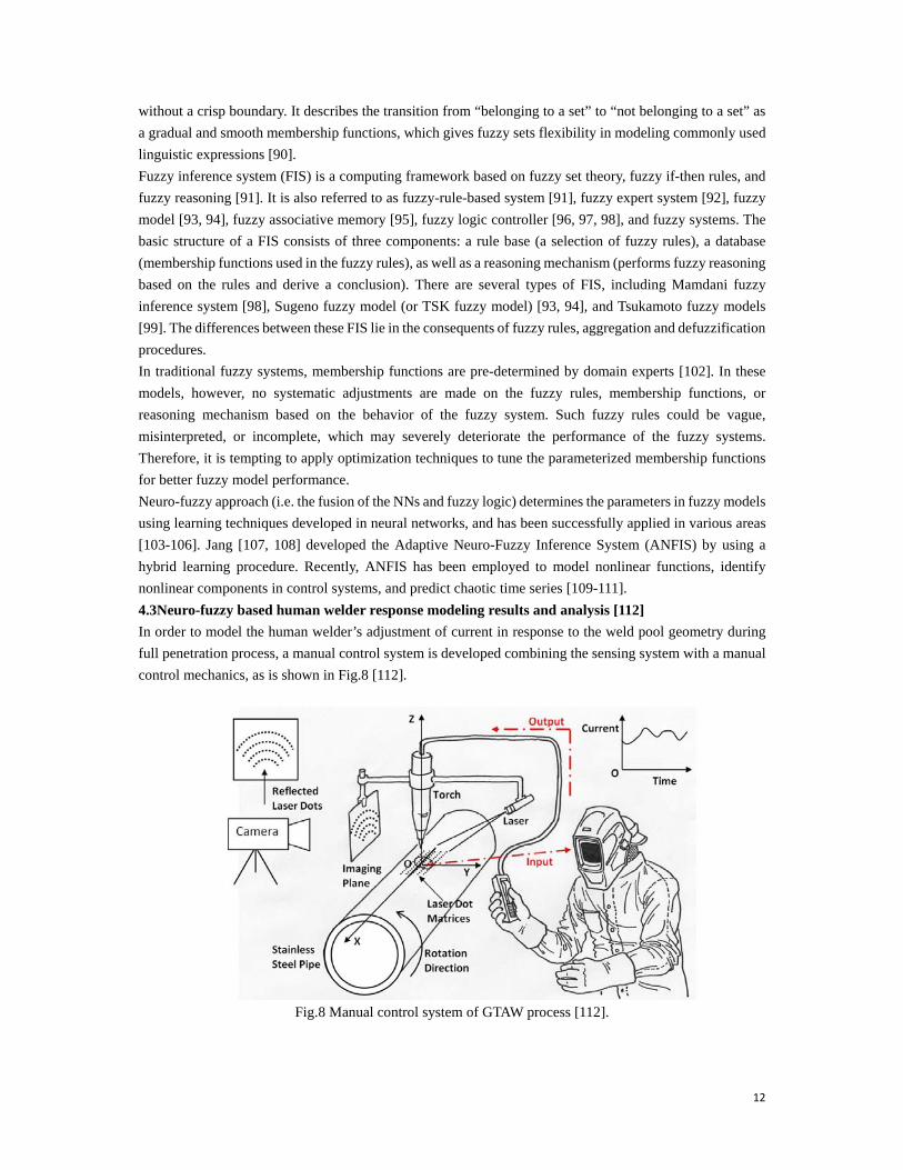
4.3Neuro-fuzzy based human welder response modeling results and analysis [112]
In order to model the human welder’s adjustment of current in response to the weld pool geometry during
full penetration process, a manual control system is developed combining the sensing system with a manual
control mechanics, as is shown in Fig.8 [112].
Fig.8 Manual control system of GTAW process [112].
13
In this system the human welder holds the current regulator while observing the geometry of weld pool and
adjusts the welding current accordingly in an effect to control the weld joint to full penetration. Nine
dynamic experiments are conducted. In experiments 1 to 3 the weldingspeed is designed to vary within
reasonable ranges [1mm/s, 2mm/s] in order to change the weld pool geometry. Then the human welder
adjusts the current to maintain the same penetration state after the change of the welding speed.The arc length
is set to 3.5mm, 4.5mm, and 5mm for these three experiments, respectively. In experiments 4 to 9 the arc
length is varying from 3mm to 5mm, and the human welder adjusts the current in response to the fluctuations
of the weld pool. The welding speed in these six experiments are 1mm/s. The dynamic variation of weld
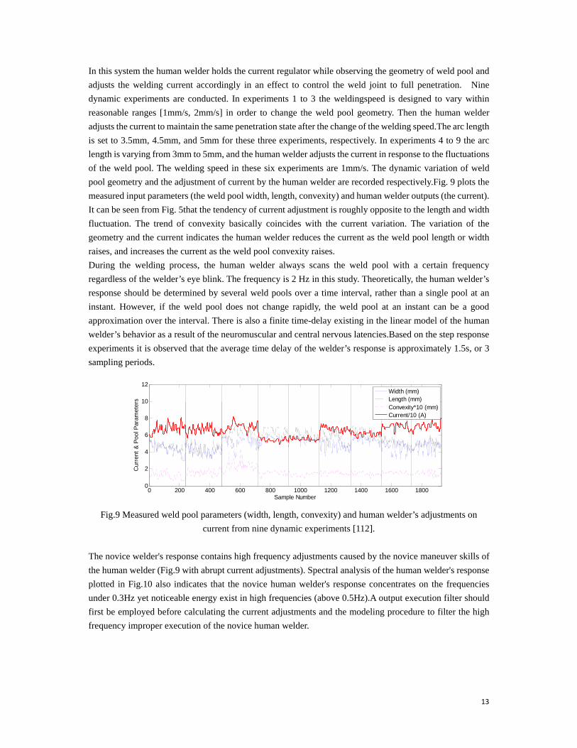
pool geometry and the adjustment of current by the human welder are recorded respectively.Fig. 9 plots the
measured input parameters (the weld pool width, length, convexity) and human welder outputs (the current).
It can be seen from Fig. 5that the tendency of current adjustment is roughly opposite to the length and width
fluctuation. The trend of convexity basically coincides with the current variation. The variation of the
geometry and the current indicates the human welder reduces the current as the weld pool length or width
raises, and increases the current as the weld pool convexity raises.
During the welding process, the human welder always scans the weld pool with a certain frequency
regardless of the welder’s eye blink. The frequency is 2 Hz in this study. Theoretically, the human welder’s
response should be determined by several weld pools over a time interval, rather than a single pool at an
instant. However, if the weld pool does not change rapidly, the weld pool at an instant can be a good
approximation over the interval. There is also a finite time-delay existing in the linear model of the human
welder’s behavior as a result of the neuromuscular and central nervous latencies.Based on the step response
experiments it is observed that the average time delay of the welder’s response is approximately 1.5s, or 3
sampling periods.
Fig.9 Measured weld pool parameters (width, length, convexity) and human welder’s adjustments on
current from nine dynamic experiments [112].
The novice welder's response contains high frequency adjustments caused by the novice maneuver skills of
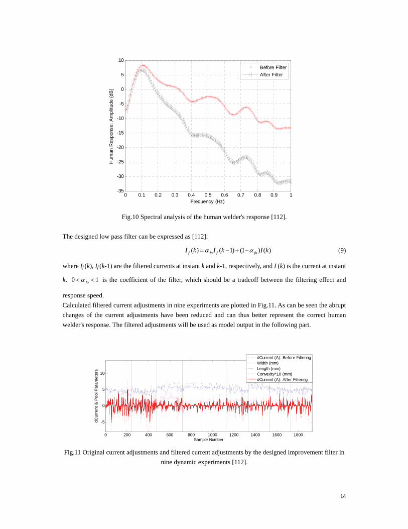
the human welder (Fig.9 with abrupt current adjustments). Spectral analysis of the human welder's response
plotted in Fig.10 also indicates that the novice human welder's response concentrates on the frequencies
under 0.3Hz yet noticeable energy exist in high frequencies (above 0.5Hz).A output execution filter should
first be employed before calculating the current adjustments and the modeling procedure to filter the high
frequency improper execution of the novice human welder.
0 200 400 600 800 1000 1200 1400 1600 18000
2
4
6
8
10
12
Sample Number
Cur
rent
& P
ool P
aram
eter
s
Width (mm)Length (mm)Convexity*10 (mm)Current/10 (A)
14
Fig.10 Spectral analysis of the human welder's response [112].
The designed low pass filter can be expressed as [112]:
( ) ( 1) (1 ) ( )f fo f foI k I k I k (9)
where If (k), If (k-1) are the filtered currents at instant k and k-1, respectively, and I (k) is the current at instant
k. 0 1fo is the coefficient of the filter, which should be a tradeoff between the filtering effect and
response speed.
Calculated filtered current adjustments in nine experiments are plotted in Fig.11. As can be seen the abrupt
changes of the current adjustments have been reduced and can thus better represent the correct human
welder's response. The filtered adjustments will be used as model output in the following part.
Fig.11 Original current adjustments and filtered current adjustments by the designed improvement filter in
nine dynamic experiments [112].
0 0.1 0.2 0.3 0.4 0.5 0.6 0.7 0.8 0.9 1-35
-30
-25
-20
-15
-10
-5
0
5
10
Frequency (Hz)
Hum
an R
espo
nse:
Am
plitu
de (
dB)
Before Filter
After Filter
0 200 400 600 800 1000 1200 1400 1600 1800
-5
0
5
10
Sample Number
dCur
rent
& P
ool
Par
amet
ers
dCurrent (A): Before FilteringWidth (mm)Length (mm)Convexity*10 (mm)dCurrent (A): After Filtering
15
In general, the human intelligent model can be written as:
( )= ( ( 3), ( 3), ( 3), ( 1))I k f W k L k C k I k (10)
The simplest form of (10) can be expressed by the following linear model [112]:
1 2 3 4( )= ( 3)+ ( 3)+ ( 3)+ ( 1)I k W k L k C k I k (11)
Using the standard least squares method the linear model can be fitted from the raw data. The identified
model is [112]:
( )=-0.0492 ( 3)-0.0049 ( 3)+1.7348 ( 3)+0.7155 ( 1)I k W k L k C k I k (12)
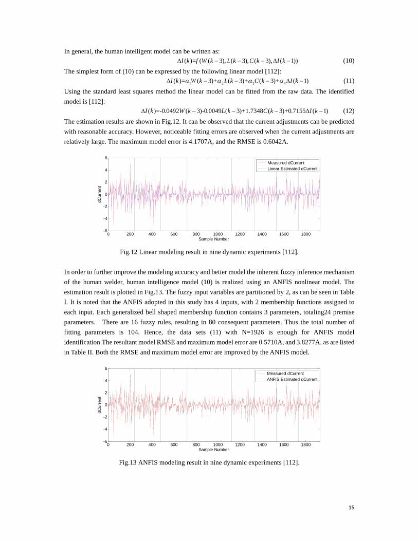
The estimation results are shown in Fig.12. It can be observed that the current adjustments can be predicted
with reasonable accuracy. However, noticeable fitting errors are observed when the current adjustments are
relatively large. The maximum model error is 4.1707A, and the RMSE is 0.6042A.
Fig.12 Linear modeling result in nine dynamic experiments [112].
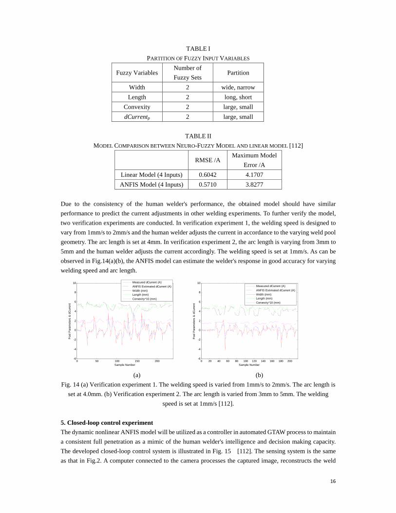
In order to further improve the modeling accuracy and better model the inherent fuzzy inference mechanism
of the human welder, human intelligence model (10) is realized using an ANFIS nonlinear model. The
estimation result is plotted in Fig.13. The fuzzy input variables are partitioned by 2, as can be seen in Table
I. It is noted that the ANFIS adopted in this study has 4 inputs, with 2 membership functions assigned to
each input. Each generalized bell shaped membership function contains 3 parameters, totaling24 premise
parameters. There are 16 fuzzy rules, resulting in 80 consequent parameters. Thus the total number of
fitting parameters is 104. Hence, the data sets (11) with N=1926 is enough for ANFIS model
identification.The resultant model RMSE and maximum model error are 0.5710A, and 3.8277A, as are listed
in Table II. Both the RMSE and maximum model error are improved by the ANFIS model.
Fig.13 ANFIS modeling result in nine dynamic experiments [112].
0 200 400 600 800 1000 1200 1400 1600 1800-6
-4
-2
0
2
4
6
Sample Number
dCur
rent
Measured dCurrentLinear Estimated dCurrent
0 200 400 600 800 1000 1200 1400 1600 1800-6
-4
-2
0
2
4
6
Sample Number
dCur
rent
Measured dCurrentANFIS Estimated dCurrent
16
TABLE I
PARTITION OF FUZZY INPUT VARIABLES
Fuzzy Variables Number of
Fuzzy Sets Partition
Width 2 wide, narrow
Length 2 long, short
Convexity 2 large, small
dCurrentp 2 large, small
TABLE II
MODEL COMPARISON BETWEEN NEURO-FUZZY MODEL AND LINEAR MODEL [112]
RMSE /A Maximum Model
Error /A
Linear Model (4 Inputs) 0.6042 4.1707
ANFIS Model (4 Inputs) 0.5710 3.8277
Due to the consistency of the human welder's performance, the obtained model should have similar
performance to predict the current adjustments in other welding experiments. To further verify the model,
two verification experiments are conducted. In verification experiment 1, the welding speed is designed to
vary from 1mm/s to 2mm/s and the human welder adjusts the current in accordance to the varying weld pool
geometry. The arc length is set at 4mm. In verification experiment 2, the arc length is varying from 3mm to
5mm and the human welder adjusts the current accordingly. The welding speed is set at 1mm/s. As can be
observed in Fig.14(a)(b), the ANFIS model can estimate the welder's response in good accuracy for varying
welding speed and arc length.
(a) (b)
Fig. 14 (a) Verification experiment 1. The welding speed is varied from 1mm/s to 2mm/s. The arc length is
set at 4.0mm. (b) Verification experiment 2. The arc length is varied from 3mm to 5mm. The welding
speed is set at 1mm/s [112].
5. Closed-loop control experiment
The dynamic nonlinear ANFIS model will be utilized as a controller in automated GTAW process to maintain
a consistent full penetration as a mimic of the human welder's intelligence and decision making capacity.
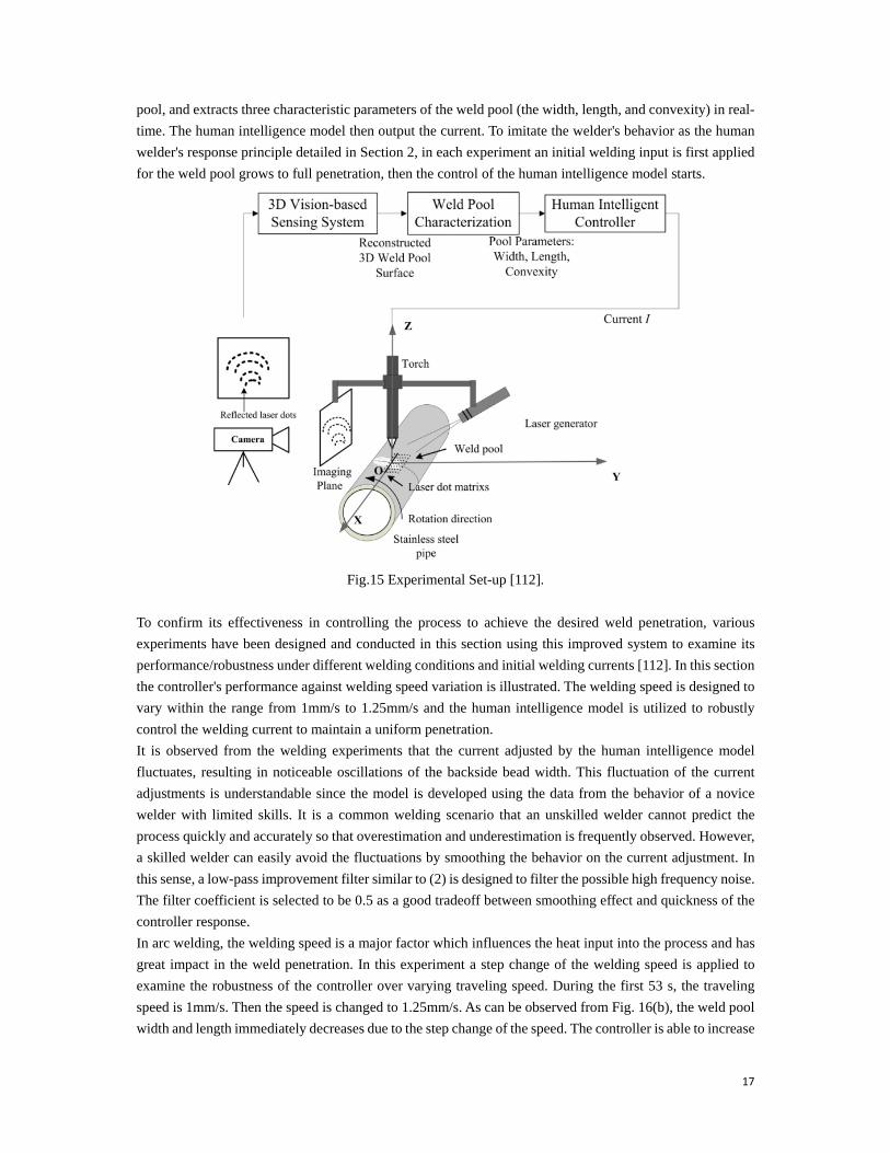
The developed closed-loop control system is illustrated in Fig. 15 [112]. The sensing system is the same
as that in Fig.2. A computer connected to the camera processes the captured image, reconstructs the weld
0 50 100 150 200-6
-4
-2
0
2
4
6
8
10
Sample Number
Poo
l Par
amet
ers
& d
Cur
rent
Measured dCurrent (A)
ANFIS Estimated dCurrent (A)
Width (mm)Length (mm)
Convexity*10 (mm)
0 20 40 60 80 100 120 140 160 180 200-6
-4
-2
0
2
4
6
8
10
Sample Number
Poo
l Par
amet
ers
& d
Cur
rent
Measured dCurrent (A)
ANFIS Estimated dCurrent (A)
Width (mm)Length (mm)
Convexity*10 (mm)
17
pool, and extracts three characteristic parameters of the weld pool (the width, length, and convexity) in real-
time. The human intelligence model then output the current. To imitate the welder's behavior as the human
welder's response principle detailed in Section 2, in each experiment an initial welding input is first applied
for the weld pool grows to full penetration, then the control of the human intelligence model starts.
Fig.15 Experimental Set-up [112].
To confirm its effectiveness in controlling the process to achieve the desired weld penetration, various
experiments have been designed and conducted in this section using this improved system to examine its
performance/robustness under different welding conditions and initial welding currents [112]. In this section
the controller's performance against welding speed variation is illustrated. The welding speed is designed to
vary within the range from 1mm/s to 1.25mm/s and the human intelligence model is utilized to robustly
control the welding current to maintain a uniform penetration.
It is observed from the welding experiments that the current adjusted by the human intelligence model
fluctuates, resulting in noticeable oscillations of the backside bead width. This fluctuation of the current
adjustments is understandable since the model is developed using the data from the behavior of a novice
welder with limited skills. It is a common welding scenario that an unskilled welder cannot predict the
process quickly and accurately so that overestimation and underestimation is frequently observed. However,
a skilled welder can easily avoid the fluctuations by smoothing the behavior on the current adjustment. In
this sense, a low-pass improvement filter similar to (2) is designed to filter the possible high frequency noise.
The filter coefficient is selected to be 0.5 as a good tradeoff between smoothing effect and quickness of the
controller response.
In arc welding, the welding speed is a major factor which influences the heat input into the process and has
great impact in the weld penetration. In this experiment a step change of the welding speed is applied to
examine the robustness of the controller over varying traveling speed. During the first 53 s, the traveling
speed is 1mm/s. Then the speed is changed to 1.25mm/s. As can be observed from Fig. 16(b), the weld pool
width and length immediately decreases due to the step change of the speed. The controller is able to increase
18
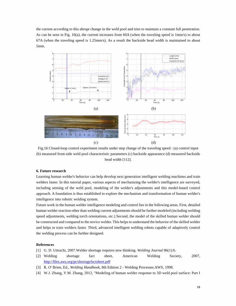
the current according to this abrupt change in the weld pool and tries to maintain a constant full penetration.
As can be seen in Fig. 16(a), the current increases from 60A (when the traveling speed is 1mm/s) to about
67A (when the traveling speed is 1.25mm/s). As a result the backside bead width is maintained to about
5mm.
(a) (b)
(c) (d)
Fig.16 Closed-loop control experiment results under step change of the traveling speed : (a) control input
(b) measured front-side weld pool characteristic parameters (c) backside appearance (d) measured backside
bead width [112].
6. Future research
Learning human welder's behavior can help develop next generation intelligent welding machines and train
welders faster. In this tutorial paper, various aspects of mechanizing the welder's intelligence are surveyed,
including sensing of the weld pool, modeling of the welder's adjustments and this model-based control
approach. A foundation is thus established to explore the mechanism and transformation of human welder's
intelligence into robotic welding system.
Future work in the human welder intelligence modeling and control lies in the following areas. First, detailed
human welder reaction other than welding current adjustments should be further modeled (including welding
speed adjustments, welding torch orientations, etc.) Second, the model of the skilled human welder should
be constructed and compared to the novice welder. This helps to understand the behavior of the skilled welder
and helps to train welders faster. Third, advanced intelligent welding robots capable of adaptively control
the welding process can be further designed.
References
[1] G. D. Uttrachi, 2007.Welder shortage requires new thinking. Welding Journal 86(1):6.
[2] Welding shortage fact sheet, American Welding Society, 2007,
http://files.aws.org/pr/shortagefactsheet.pdf
[3] R. O' Brien, Ed., Welding Handbook, 8th Edition 2 - Welding Processes.AWS, 1998.
[4] W.J. Zhang, Y.M. Zhang, 2012, "Modeling of human welder response to 3D weld pool surface: Part I
0 20 40 60 80 100 1200
1
2
3
4
5
6
7
8
Time (s)
Con
trol
Inp
uts
Current/10 (A)
Voltage/2 (V)
Speed (mm/s)
Speed 1 mm/s Speed 1.25 mm/s
0 20 40 60 80 100 1200
1
2
3
4
5
6
7
8
Time (s)
Fro
ntsi
de P
ool P
aram
eter
s
Length (mm)
Width (mm)
Convexity*10 (mm)
0 20 40 60 80 100 1200
2
4
6
8
Time (s)
Bac
ksid
e B
ead
Wid
th (
mm
)

19
- principles," Welding Journal, 91: 310s-318s.
[5] W.J. Zhang, Y.M. Zhang, 2012, "Modeling of human welder response to 3D weld pool surface: Part II
- results and analysis," Welding Journal, 91: 329s-337s.
[6] D. J. Kotecki, D. Cheever, and D. Howden, 1972 “Mechanism of ripple formation during weld
solidification," Welding Journal, 51(8): 386s- 391s.
[7] R. Renwick and R. Richardson, 1983, “Experimental investigation of GTA weld pool oscillations,"
Welding Journal, 62(2): 29s-35s.
[8] M. Zacksenhouse and D. Hardt, 1984, “Weld pool impedance identification for size measurement and
control," ASME Journal of Dynamic Systems, Measurement, and Control, 105(3): 179-184.
[9] Y.H. Xiao and G. den Ouden, 1993, “Weld pool oscillation during GTA welding of mild steel," Welding
Journal, 72(8): 428s-434s.
[10] A.J.R. Anedenroomer and G. den Ouden, 1998, “Weld pool oscillation as a tool for penetration sensing
during pulsed GTA welding," Welding Journal, 77(5):181-187.
[11] K. Andersen, G.E. Cook and R.J. Barnett, 1997, “Synchronous weld pool oscillation for monitoring
and control," IEEE Transactions on Industry Applications, 33(2): 464-471.
[12] J. Ju, Y. Suga and K. Ogawa, 2004, “Penetration control by monitoring molten pool oscillation in TIG
arc welding," International Journal of Offshore and Polar Engineering, 14(2): 145-149.
[13] B. Yudodibroto, M. Hermans, Y. Hirata, and G. den Ouden G, 2004, “Influence of filler wire addition
on weld pool oscillation during gas tungsten arc welding," Science and Technology of Welding and
Joining, 9(2): 163-168.
[14] J.D. Aussel, A.Le Brun and J.C. Baboux, 1998, “Generation acoustic wave by laser: Theoretical and
experimental study of the emission source," Ultrasonics, 24: 246-255.
[15] A. V. Clark, S. R. Schaps and C.M. Fortunko, 1992, “Well-shielded EMAT for on-line ultrasonic
monitoring of GMA welding," in Proceedings of Institute of Electrical and Electronics Engineers
Ultrasonic Symposium, Orlando, FL.
[16] G. Graham and I. Ume, 1997, “Automated system for laser ultrasonic sensing of weld penetration,"
Mechatronics, 7(8): 711-721.
[17] S. Hopko and I. Ume, 1999, “Laser generated ultrasound by material ablation using fiber optic
delivery," Ultrasonics, 37(1): 1-7.
[18] E. Siores, 1988, “Development of a real time ultrasonic sensing system for automated and robotic
welding," Ph.D. dissertation, Brunel University.
[19] A. Kita, 2005, “Measurement of weld penetration depth using non-contract ultrasound method," Ph.D.
dissertation, Georgia Institute of Technology.
[20] B. Mi and C. Ume., 2006, “Real time weld penetration depth monitoring with laser ultrasonic sensing
system," Transactions of ASME: Journal of Manufacturing Science and Engineering, 128: 280-286.
[21] W. Chen and B. Chin, 1990, “Monitoring joint penetration using infrared sensing techniques," Welding
Journal, 69(4): 181s-185s.
[22] B.A. Chin, N.H. Madsen, and J.S. Goodling, 1983, "Infrared thermography for sensing the arc welding
process," Welding Journal: 227-234.
[23] P. Banerjee et al., 1995, “Infrared sensing for on-line weld shape monitoring and control," ASME
Journal of Engineering for Industry, 117: 323-330.
[24] H. C. Wikle, R. H. Zee, and B. Chin, 1999, “Sensing system for weld process control," Journal of
Materials Processing Technology, 89-90: 254-259.
[25] J. Song and D. Hardt, 1993, “Closed-loop control of weld pool depth using a thermally based depth
20
estimator," Welding Journal, 72(10): 471s-478s.
[26] J. Song and D. Hardt, 1994, “Dynamic modeling and adaptive control of the gas metal arc welding
process," ASME Journal of Dynamic Systems, Measurement, and Control, 116(3): 405-413.
[27] S. Nagarajan, P. Banerjee, W. Chen and B. A. Chin, 1992, “Control of the welding process using
infrared sensors," IEEE Transactions on Robotics and Automation, 8(1): 86-93.
[28] C. Balfour, J. Smith, and A. Al-Shamma, 2006, “A novel edge feature correlation algorithm for real-
time computer vision-based molten weld pool measurements," Welding Journal, 85(1): 1s-8s.
[29] C. Fan, F. Lv, and S. Chen, 2009, “Visual sensing and penetration control in aluminum alloy pulsed
GTA welding," International Journal of Advanced Manufacturing Technology, 42(1):126-137.
[30] H. Ma, S. Wei, T. Lin, etc., 2010, “Binocular vision system for both weld pool and root gap in robot
welding process," Sensor Review, 30(2):116-123.
[31] M. Lin and T. Eagar, 1985, “Influence of arc pressure on weld pool geometry," Welding Journal,
64(6):163-169.
[32] S.I. Rokhlin and A.C. Guu, 1993, “A study of arc force, pool depression, and weld penetration during
gas tungsten arc welding," Welding Journal, 72(8):381-390.
[33] W. Zhang, Y. Liu, and Y. M. Zhang, 2012, “Characterization of three-dimensional weld pool surface
in gtaw," Welding Journal, 91(7):195s-203s.
[34] Y. Tang, X. Su, F. Wu, and Y. Liu, 2009, “A novel phase measuring deflectometry for aspheric mirror
test," Optic Express, 17(22):19778-19784.
[35] W. Zhao, X. Su, Y. Liu, and Q. Zhang, 2009, “Testing an aspheric mirror based on phase measuring
deflectometry," Optic Engineering, 48(10): 103603.
[36] L. Huang, C. S. Ng, and A. K. Asundi, 2011, “Dynamic three-dimensional sensing for specular surface
with monoscopic fringe reflectometry," Optics Express, 19(13): 12809-12814.
[37] S. Zhang and P. S. Huang, 2006, “High-resolution, real-time three-dimensional shape measurement,"
Optic Engineering, 45(12):123601.
[38] S. Zhang, 2010, “Recent progresses on real-time 3d shape measurement using digital fringe projection
techniques," Optic Lasers Engineering, 48(2):149-158.
[39] J. Balzer and S. Werling, 2010, “Principles of shape from specular reflection," Measurement,
43(10):1305-1317.
[40] G. J. Zhang, Z. H. Yan, and L. Lin, 2006, “Reconstructing a three- dimensional p-gmawweld pool shape
from a two-dimensional visual image," Measurement Science andTechnology, 17(7):1877-1882.
[41] Z. H. Yan, G. J. Zhang, and L. Wu, 2011, “Simulation and controlling for weld shape process in p-
gmaw based on fuzzy logic," Proceedings of the 2011 IEEE International Conference on Mechatronics
and Automation:2078-2082.
[42] C. Mnich, F. Al-Bayat, C. Debrunner, and et al., 2004, “In situ weld pool measurementusing
stereovision," Proceedings of 2004 Japan-USA Symposium on FlexibleAutomation, ASME:1-2.
[43] J. Steele, C. Mnich, C. Debrunner, T. Vincent, and S. Liu, 2005, “Development of closed-loop control
of robotic welding processes," Industrial Robot: An International Journal, 32(4):35-55.
[44] D. Y. Choong and J. Lee., 2004, “3-d measurement of weld pool using biprism stereovision sensor,"
Http://joining1.kaist.ac.kr/research/vision.htm, Seoul National University.
[45] C. X. Zhao, I. M. Richardson, S. Kenjeres, C. R. Kleijn, and Z. Saldi, 2009, “A stereo vision method
for tracking particle on the weld pool surface," Journal of Applied Physics, 105(12): 104-123.
[46] Q. Y. Du, S. B. Chen, and T. Lin, 2006, “Reconstruction of weld pool surface based onshape from
shading," Journal of Mechanical Engineering, 19(2):168-171.
21
[47] J. F. Wang, W. Y. Wang, and S. B. Chen, 2007, “Extraction of welding pool shape usinglinear
approximation."Transactions of the China Welding Institution, 28(8):54-56.
[48] J. Wang, W. Wang, and S. Chen, 2009, “Inspection of welding pool height from shading in pulsed gtaw
with wire filler," Industrial Robot: An International Journal, 36 (3):270-276.
[49] D. Zhao, J. Q. Yi, S. Chen, L. Wu, and Q. Chen, 2003, “Extraction of three-dimensionalparameters for
weld pool surface in pulsed GTAW with wire filler," Journal of Manufacturing Science and
Engineering, 125:493-503.
[50] L. P. Li, X. Q. Yang, F. Y. Zhang, and T. Lin, 2011, “Research on surface recoverof aluminum alloy
p-GTAW pool based on SFS," Robotic Welding, Intelligence andAutomation, Lecture Notes in
Electrical Engineering, 88:307-314.
[51] R. Kovacevic and Y. M. Zhang, 1996, “Sensing free surface of arc weld pool using specular reflection:
principle and analysis," Proceedings of the Institution of Mechanical Engineers, Part B, Journal of
Engineering Manufacturing, 210(6):553-564.
[52] G. Saeed and Y. M. Zhang, 2003, “Mathematical formulation and simulation of specular reaction based
measurement system for gas tungsten arc weld pool surface," Measurement Science and Technology,
14(8):1671-1682.
[53] X. P. Ai, N. S. Liu, Y. Q. Wei, X. Hu, and X. R. L. S. Wei, 2009, “Study on image acquisition in 3-d
sensor system of arc welding pool surface shape using grating projection," Proceedings of SPIE, 7506-
7528.
[54] Y. Q. Wei, N. S. Liu, X. Hu, and X. Ai, 2011, “Phase-correction algorithm of deformed grating images
in the depth measurement of weld pool surface in gas tungsten arc welding," Optical Engineering, 50:5.
[55] G. Saeed, M. J. Lou, and Y. M. Zhang, 2004, “Computation of 3d weld pool surface from the slope
field and point tracking of laser beams," Measurement Science and Technology, 15(2):389-403.
[56] H. S. Song and Y. M. Zhang, 2007, “Image processing for measurement of three-dimension al gta weld
pool surface," Welding Journal, 86(10):323s-330s.
[57] X. J. Ma and Y. M. Zhang., 2011, “Gas metal arc weld pool surface imaging: Modeling and processing,"
Welding Journal, 90(5):85s-94s.
[58] D.T. McRuer, E.S. Krendel, 1957, "Dynamic response of human operators," WADC-TR-56-524. US
Airforce.
[59] D.T. McRuer, H. R. Jex, 1967, "A review of quasi-linear pilot models," IEEE Transaction on Human
Factor Electronics, 8: 231-249.
[60] D. McRuer, D. Graham, E. Krendel, W. Reisener, 1965. "Human Pilot Dynamics in Compensatory
Systems.Technical report,"AFFDL-TR-65-15, Air Force Flight Dynamics Laboratory, Wright-
Patterson AFB. Ohio.
[61] D. L. Kleiman, S. Baron, andW. H. Levison, 1970,"An optimal model of human response, part I. Theory
and validation," Automatica, 6: 357-369.
[62] D. L. Kleiman, S. Baron, andW. H. Levison, 1970. "An optimal model of human response, part
II.Prediction of human performance in a complex task," Automatica, 6: 371-383.
[63] M. Tomizuka, and D. E. Whitney, 1975, "Optimal discrete finite preview problems (why and how is
future information important?)," Journal of Dynamics and System Measurement Control 97:319-325.
[64] M. Tomizuka, and D. E. Whitney, 1976, "The human operator in manual preview tracking (an
experiment and its modeling via optimal control),"Journal of Dynamics and System Measurement
Control 98: 407-413.
[65] L. R. Yong, 1969, "On adaptive manual control," IEEE Transaction on Man and Machine System 10:

22
292-331.
[66] W. S. Kim, F. Tendick, S. R. Ellis, andL. W.Stark, 1987, "A comparison of position and rate control of
tele-manipulation with consideration of manipulator system dynamics," IEEE Journal of Robot
Automation 3: 426-436.
[67] H. Inooka, T. Koitabashi, 1990, "Experimental studies of manual optimization in control tasks," IEEE
Control System Magazine, 10: 20-23.
[68] C. R.Kelly, 1968, Manual and automatic control, A theory of manual control and its application to
manual and automatic systems. New York: Wiley.
[69] R. B. Erwin, V. K. Robert, 1998, "Estimation of time-varying delay time in non-stationary linear
systems: an approach to monitor human operator adaption in manual tracking tasks,"IEEE transactions
on system, man and cybernetics-part A: system and humans, 28(1): 89-99.
[70] M. Arif, H. Inooka, 1999, "Iterative manual control model of human operator,"Biological Cybernetics,
81: 445-455.
[71] J. B. Davidson, and D. K. Schmit, 1992, "Modified optimal control pilot model for computer-aid design
and analysis," Technical Report TM-4384, NASA.
[72] D. B. Doman, and M. R.Anderson, 2000, "A fixed-order optimal control model of human operator
response," Automatica, 36: 409-418.
[73] Y. Uno, M. Kawato and R. Suzuki, 1989, "Formation and control of optimal trajectory in human multi-
joint arm movement-minimum torque change model,"Biological Cybernetics, 61: 89-101.
[74] M. Ito, 2000, "Internal model visualized,"Nature, 403: 153-154.
[75] H. Imamizu, S. Miyauchi, T. Tamada, etc., 2000, "Human cerebellar activity reflection an acquired
internal model of a new tool,"Nature, 403: 192-195.
[76] R. C. Miall, D. J. Weir, D. M. Wolpert, and J. F. Stein, 1993, "Is the cerebellum a Simith predictor,"
Journal of Motor Behavior , 25(3): 203-216.
[77] L. K.Chen, A. G. Ulsoy, 2000. "Identification of a nonlinear driver model via narmax modeling,"
Proceedings of American Control Conference.2533-2537.
[78] T. Tsuji, Y. Tanaka,.2005. "Tracking control properties of human-robotic systems based on impedance
control," IEEE Transactions on Systems, Man, and Cybernetics- Part A: Systems and Humans.35(4):
523-535.
[79] E. Itoh, and S.Suzuki,2005. "Nonlinear approach for human internal models: Feedforward and feedback
roles in pilot maneuver,"Systems. Man and Cybernetics. 2005 IEEE International Conference.3: 2455
– 2462.
[80] I. I. Delice, and S. Ertugrul, 2007. "Intelligent modeling of human driver: A survey,"2007 IEEE
Intelligent Vehicles Symposium. 648 – 651.
[81] S. Ertugrul, 2008. "Predictive modeling of human operators using parametric and neuro-fuzzy models
by means of computer-based identification experiment," Engineering Applications of Artificial
Intelligence. 21: 259-268.
[82] R. W.Brockett, 1999, "Minimum attention control," in Proceeding of 36th IEEE CDC San Diego,
CA:2628-2632.
[83] K. J. Astrom, B. M.Bernhardsson,2002, "Comparison of Riemann and lebesgue sampling for first order
stochastic systems," in Proceeding of 41st IEEE CDC Las Vegas, NV:2011-2016.
[84] R. Antunes, F. V. Coito, and H. Duarte-Ramos, 2011, "A linear approach towards modeling human
behavior," DoCEIS, IFIP AICT 349: 305-314.
[85] O. Ceik, S. Ertugrul, 2007, "Predictive human operator model to be utilized as controller using linear,
23
neuro-fuzzy and fuzzy-ARX modeling techniques," Engineering Applications of Artificial
Intelligence, 23:595-603.
[86] N.Yamada, S.Inagaki, T.Suzuki, etc., 2006, "Behavior modeling in man-machine cooperative system
based on stochastic switched dynamics,"Proceeding of 2006 IEEE international Conference on
Robotics and Automation:3618-3623.
[87] H. Okuda, S. Hayakawa, T. Suzuki, N. Tsuchida, 2011, "Parameter design of switched assist controller
for man-machine cooperative system with human behavior model based on hybrid system,"Electrical
Engineering in Japan, 177(1): 55-63.
[88] K. Tervo, 2010, "Discrete data-based state feedback model of human operator,"2010 IEEE/ASME
International Conference on Mechatronics and Embedded Systems and Applications (MESA): 202- 207.
[89] K. Tervo and A. Mannien, 2010, "Analysis of model orders in human dynamics identification using
linear polynomial and Hammerstein-wiener structures,"2010 IEEE International Conference on
Networking, Sensing and Control: 614- 620.
[90] L. A. Zadeh, 1965, "Fuzzy sets," Information and Control, 8:338-353.
[91] J.S.R. Jang, E. Mizutani, and C.-T. Sun, 1997, Neuro-Fuzzy and Soft Computing, A Computational
Approach to Learning and Machine Intelligence, Prentice Hall, Upper Saddle River, NJ.
[92] A. Kandel, 1992, Fuzzy expert systems, CRC Press, Inc., Boca Raton, FL.
[93] M. Sugeno and G. T. Kang, 1988, "Structure identification of fuzzy model," Fuzzy Sets and Systems,
28:15-33.
[94] T. Takagi and M. Sugeno, 1985, "Fuzzy identification of systems and its applications to modeling and
control," IEEE Transactions on Systems, Man and Cybernetics, 15:116-132.
[95] B. Kosko, 1991, Neural networks and fuzzy systems: a dynamical systems approach, Prentice Hall,
Upper Saddle River, NJ.
[96] C.-C. Lee, 1990, "Fuzzy logic in control systems: fuzzy logic controller-part 1," IEEE Transactions on
Systems, Man and Cybernetics, 20(2):404-418.
[97] C.-C. Lee, 1990, "Fuzzy logic in control systems: fuzzy logic controller-part 2," IEEE Transactions on
Systems, Man and Cybernetics, 20(2):419-435.
[98] E.H. Mamdani and S. Assilian,1975, "An experiment in linguistic synthesis with a fuzzy logic
controller," International Journal of Man-Machine Studies, 7(1):1-13.
[99] Y. Tsukamoto, 1979, An approach to fuzzy reasoning method. In Madan M. Gupta, Rammohan K.
Ragade, and Ronald R. Yager, editors, Advances in fuzzy set theory and applications:137-149, North-
Holland, Amsterdam.
[100] A.E. Bryson and Y.-C. Ho, 1969, Applied optimal control, Blaisdell, New York.
[101] D.E. Rumelhart, G.E. Hinton, and R.J. Williams, 1986, "Learning internal representations by error
propagation," Parallel distributed processing: explorations in the microstructure of cognition, 1:318-
362, MIT Press, Cambridge, MA.
[102] E.H. Mamdani, and S.Assilian,1975, “An experiment in linguistic synthesis with a fuzzy logic
controller,” International Journal of Mechanical Studies, 7(1): 1-13.
[103] K. Hayashi, et.al., 1995, “Neuro fuzzy transmission control for automobile with variable loads,”
IEEE Transactions on Control Systems Technology, 3(1): 49-53.
[104] K. Tanaka, M.Sano, and H. Watanabe, 1995, “Modeling and Control of Carbon Monoxide
Concentration Using a Neuro-Fuzzy Technique,” IEEE Transactions on Fuzzy Systems, 3(3): 271-279.
[105] R. Kovacevic, and Y.M. Zhang, 1997, “Neurofuzzy model-based weld fusion state estimation,”
IEEE Control System Magazine, 17(2): 30-42.

24
[106] Y.M. Zhang, and R.Kovacevic, 1998, “Neurofuzzy model based control of weld fusion zone
geometry," IEEE Transactions on Fuzzy Systems, 6(3): 389-401.
[107] J.S.R. Jang, and C.T. Sun, 1995, “Neuro-Fuzzy Modeling and Control”, Proceedings of the IEEE,
83(3): 378-406.
[108] J.S.R. Jang, 1993, “ANFIS: Adaptive-network-based Fuzzy Inference Systems”, IEEE
Transactions on Systems, Man, and Cybernetics, 23(3): 665-685.
[109] W. Lih, et.al., 2008, “Adaptive Neuro-Fuzzy Inference System Modeling of MRR and WIWNU
in CMP Process with Sparse Experimental Data,” IEEE Transactions on Automation Science and
Engineering, 5(1): 71-83.
[110] J. Zhai, et.al., 2009, “ The Dynamic Behavioral Model of RF Power Amplifiers with the Modified
ANFIS,”IEEE Transactions on Microwave Theory and Techniques, 57(1): 27-35.
[111] M. Imen, M. Mansouri, and M.A.Shoorehdeli, 2011, “Tracking Control of Mobile Robot Using
ANFIS,” Proceedings of the 2011 IEEE International Conference on Mechatronics and Automation,
Beijing, China.
[112] Y.K. Liu, W.J. Zhang, Y.M. Zhang, 2013, "Neuro-fuzzy Based Human Intelligence Modeling and
Robust Control in Gas Tungsten Arc Welding Process," Proceedings of the 2013 American Control
Conference (2013 ACC), Washington DC, USA.