a trusted autopilot architecture for gps denied and...
TRANSCRIPT

1
A TRUSTED AUTOPILOT ARCHITECTURE FOR GPS-DENIED AND EXPERIMENTAL UAV OPERATIONS
Anthony Spears*, Lee Hunt†, Mujahid Abdulrahim‡, Al Sanders§, Jason Grzywna**
Unmanned and autonomous systems require a great deal of human trust, espe-
cially in order to gain acceptance for high-risk mission applications. In the aerial
domain, loss of vehicle control, crashing or leaving the safety of the designated
range can present a hazard to human safety as well as property. This represents a
key barrier in current safety review processes when considering an experimental
autopilot. Our approach couples a trusted autopilot with the experimental autopi-
lot in order to facilitate testing and evaluation of immature technology, while
ensuring safety is maintained. Such a system performs in a similar manner to the
analogous scenario where an experienced human co-pilot oversees an unexperi-
enced pilot. The Merlin trusted autopilot architecture is presented here, leverag-
ing visual odometry as an additional redundancy in the standard GPS/IMU navi-
gation system, while also integrating novel failsafe behaviors representative of
the many dangerous failure situations that are commonly encountered on a UAV
test range. In addition, this robust autopilot architecture, with its multiple redun-
dancies, failsafe behaviors and system monitoring functions, presents an appeal-
ing platform for testing new and experimental UAV flight packages. Custom
hardware has been developed to host this trusted autopilot with an open-
interface approach in order to facilitate extensibility to these experimental de-
signs. Initial architecture design and results from testing of the failsafe behaviors
and visual odometry navigation system are presented.
INTRODUCTION
The use of unmanned and autonomous systems in high-risk missions must demonstrate a high-
degree of reliability and fault tolerance. In the aerial domain, loss of vehicle control, crashing or
leaving the permitted airspace can present a hazard to humans as well as property. As a result of
these challenges and the current regulatory environment, it is very difficult to obtain safety re-
view approval for experimental flights. Airworthiness safety review boards are accustomed to
assessing manned aircraft operations, which typically include redundancy and safety precautions
that are more stringent than the systems commonly used on UAVs. However, airspace integration
is currently an important consideration throughout government and industry and includes a $2.8
* Computer Vision Researcher, Prioria Robotics, 606 SE Depot Ave, Gainesville, FL 32601. † R&D Services Division Program Manager, Prioria Robotics, 606 SE Depot Ave, Gainesville, FL 32601. ‡ Senior Controls Engineer, Prioria Robotics, 606 SE Depot Ave, Gainesville, FL 32601. § Computer Vision Program Manager, Prioria Robotics, 606 SE Depot Ave, Gainesville, FL 32601. ** Chief Technology Officer, Prioria Robotics, 606 SE Depot Ave, Gainesville, FL 32601.
2
billion airspace integration effort by NASA 1
. A robust autopilot system with multiple failsafe
navigation methods is being developed for NASA Langley Research Center to improve the safety
of commercial and experimental flight operations. Our approach couples a trusted autopilot with
the experimental autopilot in order to facilitate testing and evaluation of immature technology,
while ensuring safety is maintained. The trusted autopilot is designed to satisfy the stringent re-
quirements of airworthiness safety review boards with respect to control authority, fly-away pre-
vention, fault-tolerance, and operator control. Additionally, our autopilot is designed to permit
safe transfer of control authority between the internal and external control laws. This autopilot
architecture provides an appealing, extensible platform for testing new experimental flight pack-
ages. In these applications, the trusted autopilot will be able to detect failures in the experimental
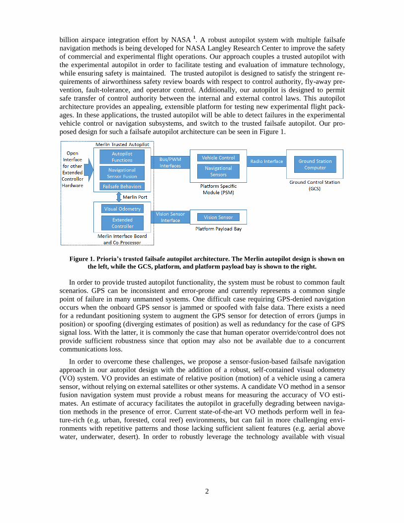
vehicle control or navigation subsystems, and switch to the trusted failsafe autopilot. Our pro-
posed design for such a failsafe autopilot architecture can be seen in Figure 1.
Figure 1. Prioria’s trusted failsafe autopilot architecture. The Merlin autopilot design is shown on
the left, while the GCS, platform, and platform payload bay is shown to the right.
In order to provide trusted autopilot functionality, the system must be robust to common fault
scenarios. GPS can be inconsistent and error-prone and currently represents a common single
point of failure in many unmanned systems. One difficult case requiring GPS-denied navigation
occurs when the onboard GPS sensor is jammed or spoofed with false data. There exists a need
for a redundant positioning system to augment the GPS sensor for detection of errors (jumps in
position) or spoofing (diverging estimates of position) as well as redundancy for the case of GPS
signal loss. With the latter, it is commonly the case that human operator override/control does not
provide sufficient robustness since that option may also not be available due to a concurrent
communications loss.
In order to overcome these challenges, we propose a sensor-fusion-based failsafe navigation
approach in our autopilot design with the addition of a robust, self-contained visual odometry
(VO) system. VO provides an estimate of relative position (motion) of a vehicle using a camera
sensor, without relying on external satellites or other systems. A candidate VO method in a sensor
fusion navigation system must provide a robust means for measuring the accuracy of VO esti-
mates. An estimate of accuracy facilitates the autopilot in gracefully degrading between naviga-
tion methods in the presence of error. Current state-of-the-art VO methods perform well in fea-
ture-rich (e.g. urban, forested, coral reef) environments, but can fail in more challenging envi-
ronments with repetitive patterns and those lacking sufficient salient features (e.g. aerial above
water, underwater, desert). In order to robustly leverage the technology available with visual

3
odometry, it is important to know when to use VO and when to reject it based on poor accuracy
indications.
In the case of a combined GPS and VO failure, the trusted autopilot system will gracefully de-
grade (through sensor fusion) to inertial navigation - a final redundancy available in almost all
unmanned vehicles. With three positioning methods available to an UAV (GPS, VO, inertial nav-
igation), the vehicle will be able to optimally leverage each of the methods through sensor fusion
to obtain a robust navigation solution. This requires the system to have knowledge of the real-
time accuracy of each independent navigation subsystem, and to be able to seamlessly and grace-
fully switch between them when needed. Such a design, as presented here, provides a robust
method for autonomous navigation and position estimation using a redundant and multi-layered
failsafe approach.
To further enhance robustness and fault-tolerance, the trusted autopilot provides additional
system monitoring and failsafes on top of the navigational failsafe. In addition to failsafes com-
mon in standard autopilots, this trusted autopilot design incorporates a loss-of-controllability (e.g.
stall) prevention failsafe and computer heartbeat failsafe which monitors the integrity of the ex-
perimental extended controller. The trusted autopilot autonomously assumes control in the face of
any system fault which would otherwise result in an unsafe or unrecoverable failure.
In order to optimally implement the desired autopilot architecture for our current applications,
a custom hardware design has been developed in parallel with the failsafe software development.
This design represents an implementation of our objective autopilot system design and provides a
testbench for most experimental control systems. While this hardware design can be used in a
stand-alone configuration, it can also be integrated with custom extended autopilot hardware.
Prioria’s autopilot hardware architecture is divided between two main components – a flight con-
troller based on the Pixhawk PX4 architecture, and an onboard vision computer which hosts the
visual odometry algorithm, and can also host an experimental controller when desired. An illus-
tration of the redundant control switching that takes place in the trusted autopilot can be seen in
Figure 2.
Figure 2. Prioria’s trusted failsafe redundant command and control architecture. This trusted au-
topilot autonomously arbitrates between human operator, experimental autopilot, and trusted auto-
pilot control of the UAV flight systems. All control commands must go through the trusted autopilot
prior to flight system actuation and control implementation.
The vision computer (Figure 1) hosts the visual odometry algorithms and provides the re-
sources needed for implementation of an extended experimental controller. While the onboard
vision computer adheres to the required interfacing architecture of the failsafe autopilot, any
hardware platform can be used to host an extended controller. The hardware and software inter-
face between the failsafe autopilot and any extended experimental controller is defined in a
Prioria Interface Control Document (ICD) available to any party interested in developing such an
experimental autopilot or controller.

4
This novel trusted failsafe autopilot architecture is discussed herein and maintains the integrity
and safety of an unmanned vehicle through careful autonomous oversight of any experimental
controller, and assumption of control in the case of a fault. By open-sourcing this extensible auto-
pilot interface, Prioria intends to encourage the progression of new unmanned vehicle technology
in a safe and robust manner. We also intend this architecture to provide some of the groundwork
needed to facilitate future safety review processes for experimental unmanned flight systems, and
it has already successfully performed this role. The modularity and configurability of the autopi-
lot system is illustrated through four examples in Figure 3.
Figure 3. Four example configurations of the Merlin autopilot system. The trusted autopilot can
be used stand-alone (a), an extended controller can be added through implementation on the vision
computer (b), a camera can be added to implement visual navigation GPS-failsafe (c), and custom
third-party external hardware can be added to implement an extended controller (d).
BACKGROUND
Current Failsafes
For almost all state-of-the-art UAV systems, field operations rely on a failsafe approach in-
volving a team of human operators to oversee and control the vehicle throughout the mission to
ensure safety is maintained. Human operators (usually with pilot certifications and flight experi-
ence) will monitor the UAV remotely and in real-time during the mission, both through direct
line-of-sight and through video and flight data telemetry. Upon detection of a fault condition in
the autonomous operation of the vehicle, a human operator can override the autonomous control
and assume direct or augmented remote control to safely recover the vehicle. This functionality is
similar to that inherited from manned flight operations in which emergency procedures for a mal-
functioning autopilot require the human pilot to disengage automatic control and manually pilot
the aircraft. While this is the standard for mature vehicle systems, additional attentive oversight is
required for experimental and immature technology. Such experimental flight testing is difficult
to undertake, as the system must adhere to many strict safety requirements in order to obtain ap-
proval from a safety review board. During experimental control system testing, an overseer is also
required to make decisions on switching between the experimental and mature controllers in addi-
tion to override decision making.
Some common fault states in UAVs during vehicle operations include loss of GPS, loss of
communications, computational or software fault, loss of control authority, violation of flight or
airspace envelope, and entering the vehicle into an uncontrollable state (e.g. stall). In a truly ro-
bust system, each of these fault-states requires a reliable recovery solution. Human-override pro-
vides a sufficient recovery solution for some of these faults, but is far from a complete solution.
Many times multiple fault states can be encountered simultaneously, such as a loss of GPS and
5
communications, especially common with experimental radio payloads or jamming situations.
The addition of an experimental controller adds complexity and difficulty to the notion of a fail-
safe system.
Autonomy present on UAVs provides failsafe behaviors in the case of an unrecoverable fault
with communication to a human operator. The failsafe behavior is often a “Loiter” command in
which the vehicle circles or hovers about the location of the failure while awaiting a subsequent
operator command. In cases where the vehicle has no remaining battery or fuel capacity, or en-
counters another serious error and cannot remain airborne, the vehicle is often commanded to per-
form a “Land Immediately” behavior. However, if the vehicle is determined to have reliable con-
trol and position information, a more complex “Return Home” behavior can be implemented.
While baseline behaviors such as these are common in mature autonomy systems, more complex
failsafe behaviors would provide additional capabilities for robust systems. The most challenging
aspect of implementing these more complex failsafe behaviors is the current immaturity of the
sensing and fault-awareness frameworks available in many systems. In order for failsafe autono-
my to make reliable behavioral decisions, detailed knowledge of the UAV system state and faults
must be monitored, detected and communicated.
Survey of Existing Autopilot Failsafes
Failsafe capabilities in UAVs are of great importance and need in real-world systems, and thus
all common autopilot systems available today integrate at least some limited failsafe capabilities.
All aerial vehicles must be capable of ensuring safety through common failures such as loss of
command link, loss of communications, and loss of GPS. A few examples of commercially avail-
able autopilots include Pixhawk, Kestrel, Airware, and MicroPilot. The Pixhawk autopilot hard-
ware platform is an open source design, upon which the PX4 middleware is run. The PX4 flight
stack and ArduPilot* autopilot flight control software can both be run on top of this common PX4
middleware and Pixhawk hardware, and provide the most common open source autopilot soft-
ware implementations. Pixhawk failsafe detection capabilities include geofence, engine failure,
data link loss, GPS loss, loss of barometric altitude, and RC loss†. Pixhawk failsafe actions in-
clude flight termination, engine failure mode, data link loss mode, controlled flight termination,
return to launch, and RC loss (loiter followed by flight termination if not recovered). Pixhawk
does not provide a battery failsafe. Lockheed Martin’s Kestrel autopilot is proprietary, but pro-
vides failsafe algorithms to return to base and auto-land in emergency situations such as low bat-
tery or loss of communications with the ground control station. This includes multiple user-
configurable failsafes such as loss of communications, loss of GPS, low battery, critical battery,
loss of RC, flight termination, terrain elevation data and height above ground‡. The newest ver-
sion of Kestrel allows sensors to cross check each other for accuracy and fault detection§.
Prioria intends to extend the state-of-the art failsafe capabilities of current autopilots with our
Merlin extensible autopilot hardware and open-source-compatible software. A mutli-layer archi-
tecture is proposed which integrates both a trusted failsafe and experimental autopilot to avoid
many failures which result from flying immature technology. Additional failsafes including loss
of experimental autopilot computer and loss of controllability (from poor experimental control)
*http://plane.ardupilot.com/wiki/advanced-failsafe-configuration/ † https://pixhawk.org/users/failsafe ‡http://www.lockheedmartin.com/content/dam/lockheed/data/ms2/documents/procerus/Kestrel_v2.4_04_18_2008.pdf
§http://www.prnewswire.com/news-releases/lockheed-martin-kestrel-autopilot-now-available-for-international-sales-
259221691.html
6
are included in this new failsafe system. We also increase the robustness of other common fail-
safe behaviors through an additional navigational system (visual odometry) and sensor fusion, as
well as fault-awareness of the navigation law and other vehicle subsystems. This extensible auto-
pilot technology allows for robust testing of experimental autopilot and payload technology while
ensuring integrity of the system through autonomous oversight.
Current Failsafe Limitations
The current standards for failsafes in UAV autopilot systems provide sufficient capabilities for
many common missions, but encounter limitations in experimental and complex mission scenari-
os. Navigation and localization methods are a key point of failure for many systems. GPS signals
can be unreliable and inertial sensors (IMUs) exhibit inherent noise and drift over time. Current
autopilot systems cannot detect intermittent GPS error, which can cause control problems and
even fly-aways if not filtered prior to the control system. Unreliable positioning systems can pre-
vent use of “Return to Home” behaviors in these autonomous systems, limiting their robustness.
The common overseer relationship between the human operators and the onboard vehicle au-
tonomy has proven effective in many cases through the recent development of UAVs. However,
there are multiple limitations to this approach. The human-override functionality requires a robust
and persistent communication and control link between the human and vehicle, which can be eas-
ily violated in many real-world cases (especially in experimental missions). Loss-of-GPS faults
are often accompanied by a loss in communications (and therefore human-override capabilities),
both stemming from radio frequency (RF) interference. Many current autopilot systems have lim-
itations in the ability to detect a loss of GPS or communications, which prohibit recovery. This
overseer approach is very demanding in terms of logistical support and human effort require-
ments, and is therefore prohibitive in many applications. Finally, human operators can induce
their own fault-states in the vehicle from incorrect control, and can benefit from another layer of
oversight, even in operator-override mode. These limitations provide the motivation for addition-
al autonomy and failsafes in UAV systems to further the capabilities of these unmanned systems
and reduce the dependency on direct operator control.
Visual odometry
The common navigational sensors leveraged in UAV autopilot systems include GPS sensors,
inertial measurement units (IMUs), compass sensors, and pressure sensors. Altimeter and com-
pass sensors commonly provide reliable and absolute measurements of altitude and heading re-
spectively. GPS is heavily relied upon to obtain latitude and longitude readings, but can be unre-
liable, especially in the presence of any RF interference. Inertial sensors are subject to large
amounts of noise and drift over time, and cannot be relied upon over long durations or distances.
The difficulty in developing additional reliable latitude/longitude sensing modalities to alleviate
the limitations of GPS and inertial sensors has been the subject of much research over the past
few decades. One popular area of research on this topic involves the use of camera sensors and
computer vision as a navigational approach. Such methods are termed visual navigation, visual
odometry, or simultaneous localization and mapping (SLAM). Visual navigation refers to the
broad research area, while visual odometry refers to the estimation of the change in camera state
(position and rotation) between image frames. Simultaneous localization and mapping refers to
the Bayesian framework for concurrently estimating an agent’s location and mapping features in
the surrounding environment given sensor observations over time and motion of the agent 2
.
SLAM persists knowledge of the system over time and provides loop closure functionality to
eliminate accumulated drift error in the navigational state estimation.

7
Visual odometry (VO) is used to incrementally estimate the relative position of a camera
(which can be extrapolated to the attached vehicle platform) between image frames. These rela-
tive position estimates can be accumulated and filtered to produce a trajectory estimate over an
extended period of vehicle motion. Visual odometry methods provide useful information for ve-
hicle trajectory estimation provided sufficient light, texture, and overlap between successive im-
ages exist. While such an approach is subject to accumulation of error over time, as with any dead
reckoning or odometry method, SLAM can be implemented on top of VO to zero this drift error.
A good background paper on visual odometry theory is presented by Scaramuzza 3.
With the current state of open source software, many implementations of VO and SLAM are
readily available and can often be easily adapted to an unmanned vehicle platform. Some of these
implementations, considered in the design of the trusted autopilot, are detailed below. All of these
have been previously implemented on unmanned aerial vehicle systems.
PX4FLOW 4
is a monocular hardware/software optical flow smart camera package which can
be used to provide an estimate of real-time visual odometry. This system can be easily integrated
with the Pixhawk PX4 autopilot used on many unmanned aerial vehicles (UAVs). This approach
is optimized for computation efficiency to provide a high frame-rate solution to visual odometry.
Optical flow on a 4x4 pixel patch and 64 patches per frame is performed and aggregated into a
histogram of values to find the most popular estimate for optical flow to a one pixel accuracy.
This assumes a parallel plane between the ground plane and the image plane. Velocity can be cal-
culated with knowledge of distance to the ground and camera focal length. Using these simplify-
ing assumptions, velocity estimates can be rapidly obtained, but at the expense of robustness and
adaptability. For many UAV missions, the assumptions here are reasonable and sufficient accura-
cy is obtained. However, performance can degrade in the case of non-planar (e.g. trees), non-
parallel or sloping ground conditions. The one pixel accuracy limit is also prohibitive to some
missions requiring high precision. The PX4FLOW approach provides a useful fast and straight-
forward implementation of optical flow for visual odometry, but can be limited for use in high-
risk or safety-critical applications due to the lack of adaptability and robustness.
Parallel tracking and mapping (PTAM) 5
is a SLAM approach which separates tracking and
mapping tasks into two parallel threads for computational efficiency and scalability. Bundle ad-
justment is performed over keyframes to optimize pose estimates and feature positions. While this
method was initially designed for and limited to small scale desktop environments, Weiss6 pre-
sents a modified version for use in large scale outdoor environments. This modified method is
now commonly used in many micro aerial vehicles, including the SFLY project. This is an exam-
ple of a common, readily available, open source algorithm for use in visual odometry with UAVs.
Since PTAM is not only a visual odometry method, but a full SLAM method, loop closure can be
performed provided sufficiently salient global features, which reduces error accumulation.
Semi-direct visual odometry (SVO) 7
eliminates the need for costly feature extraction and ro-
bust matching for a more computationally tractable real-time VO implementation. The algorithm
operates directly on pixel intensities which results in sub-pixel precision at high frame-rates. Fea-
ture extraction is only performed at a limited number of keyframes (the scaling limitation). The
SVO algorithm does require initialization prior to use, leveraging the first two keyframes and as-
suming a planar scene to calculate homography. Like PTAM, this is an algorithm that has readily
available implementations for use on UAVs, and is designed for real-time implementation.
Visual navigation can provide a robust augmentation to current navigation systems (i.e. GPS
and inertial navigation), especially in GPS-denied and experimental mission scenarios. There ex-
ist multiple freely-available visual navigation implementations that are relatively mature and have
been integrated into previous UAV systems. One real-time bottleneck in visual odometry is fea-

8
ture registration, and is the focus of much current research. A real-time bottleneck in SLAM ap-
proaches is the scalability of the map framework, also a focus of much current research. Another
limitation of many current visual navigation methods is the need for quality and fault-aware
measurements. The introduction of fault-aware capabilities would increase the robustness of these
systems, and facilitate integration into a larger navigational sensor fusion framework in these
UAV systems of interest. In order to integrate visual odometry into Prioria’s trusted autopilot sys-
tem, custom hardware and software has been developed and is discussed below.
FAILSAFE ARCHITECTURE
The main contributions of the failsafe architecture presented here is a combination of redun-
dancy through sensor fusion and broad fault-awareness. One of the main points of failure in real-
world UAV missions is the vehicle’s navigational system. Thus, robust navigational capabilities
are an important focus of this failsafe autopilot architecture. An EKF approach to sensor fusion
forms the basic architecture for navigational redundancy here. In addition to the common GPS
and inertial systems, a third level of redundancy is added in the form of a visual odometry system.
Enhanced fault-awareness capabilities of these three systems have been investigated to provide
improved integration in the sensor fusion framework. Additional failsafe detections and behaviors
have also been developed for the autopilot in order to provide fault-awareness and recovery capa-
bility for many common fault scenarios encountered across a broad spectrum of UAV platforms,
and especially in experimental deployments. Custom hardware has been developed as part of this
effort in order to optimally host Prioria’s autopilot architecture.
Navigational Failsafe
The core of the navigational failsafe presented here is an EKF sensor fusion framework and
three redundant navigational sensing modalities (GPS, inertial, visual odometry). Note that abso-
lute altitude and heading can be obtained fairly accurately from pressure and compass sensors
respectively, which limits the localization problem largely to latitude and longitude estimation.
GPS receivers provide absolute latitude, longitude, and altitude measurements provided that sig-
nal of sufficient fidelity can be received from a sufficient number of GPS satellites (at least three
to four). However, GPS system performance degrades in urban environments, indoor environ-
ments, and other locations with excessive signal reflections, signal loss, and RF interference (both
accidental and deliberate. Commercial GPS systems are also limited in accuracy to approximately
3.5 meters in the horizontal direction*, but provide absolute measurements which do not accumu-
late drift error over time. Inertial sensors such as accelerometers and gyroscopes provide meas-
urements of acceleration and angular velocity respectively, but tend to be inherently noisy (espe-
cially in low-cost systems). As position is obtained through double integration of noisy accelera-
tion measurements in IMUs, inertial sensor estimates accumulate significant drift error over time.
However, these sensors can be utilized to provide high-resolution and high-rate motion infor-
mation over short periods of time.
Visual odometry methods inherit a few limitations of inertial sensors, such as accumulation of
drift error, since frame-to-frame velocity is measured instead of absolute position. However, drift
error can be eliminated with loop closure constraints by revisiting previous or known locations, if
allowed for in the application’s trajectory planning. Visual odometry methods were previously
limited by computational constraints (due to image processing), but these limitations are now be-
*http://www.gps.gov
9
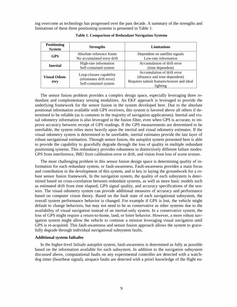
ing overcome as technology has progressed over the past decade. A summary of the strengths and
limitations of these three positioning systems is presented in Table 1.
Table 1. Comparison of Redundant Navigation Systems
Positioning
System Strengths Limitations
GPS Absolute reference frame
No accumulated error drift
Dependent on satellite signals
Low-rate information
Inertial High-rate information
Self-contained system
Accumulation of drift error
(time dependent)
Visual Odom-
etry
Loop-closure capability
(eliminates drift error)
Self-contained system
Accumulation of drift error
(distance and time dependent)
Requires salient features/texture and ideal
lighting
The sensor fusion problem provides a complex design space, especially leveraging three re-
dundant and complementary sensing modalities. An EKF approach is leveraged to provide the
underlying framework for the sensor fusion in the system developed here. Due to the absolute
positional information available with GPS receivers, this system is favored above all others if de-
termined to be reliable (as is common in the majority of navigation applications). Inertial and vis-
ual odometry information is also leveraged in the fusion filter, even when GPS is accurate, to im-
prove accuracy between receipt of GPS readings. If the GPS measurements are determined to be
unreliable, the system relies more heavily upon the inertial and visual odometry estimates. If the
visual odometry system is determined to be unreliable, inertial estimates provide the last layer of
robust navigational estimation. Through sensor fusion, the autopilot system presented here is able
to provide the capability to gracefully degrade through the loss of quality in multiple redundant
positioning systems. This redundancy provides robustness to distinctively different failure modes:
GPS from interference, IMU from calibration error or drift, and vision from loss of scene texture.
The most challenging problem in this sensor fusion design space is determining quality of in-
formation for each redundant system, or fault-awareness. Fault-awareness provides a main focus
and contribution in the development of this system, and is key in laying the groundwork for a ro-
bust sensor fusion framework. In the navigation system, the quality of each subsystem is deter-
mined based on cross-correlation between redundant systems, as well as more basic models such
as estimated drift from time elapsed, GPS signal quality, and accuracy specifications of the sen-
sors. The visual odometry system can provide additional measures of accuracy and performance
based on computer vision theory. Based on the fault state of each navigational subsystem, the
overall system performance behavior is changed. For example if GPS is lost, the vehicle might
default to change behaviors, but may not need to be as conservative as other systems due to the
availability of visual navigation instead of an inertial-only system. In a conservative system, the
loss of GPS might require a return-to-home, land, or loiter behavior. However, a more robust nav-
igation system might allow the vehicle to continue a mission leveraging visual navigation until
GPS is re-acquired. This fault-awareness and sensor fusion approach allows the system to grace-
fully degrade through individual navigational subsystem faults.
Additional system failsafes
In the higher-level failsafe autopilot system, fault-awareness is determined as fully as possible
based on the information available for each subsystem. In addition to the navigation subsystem
discussed above, computational faults on any experimental controller are detected with a watch-
dog timer (heartbeat signal), airspace faults are detected with a priori knowledge of the flight en-

10
velope, and controllability faults (e.g. stall) are detected with thresholds on angular state (roll,
pitch, yaw).
While the autopilot is configurable, an example configuration of the failsafe autopilot system
can be illustrated through the default detection and behavior set. If GPS is lost, the vehicle is
commanded to return home using one or both of the alternate navigation sub-systems, vision and
IMU. In the case of GPS spoofing or small errors in GPS, detected through a comparison with the
visual and inertial systems, the vehicle is commanded to return home again using one or both of
the alternate navigation sub-systems. This behavior is designed to prevent fly-aways resulting
from bad GPS reception. If the airspace boundary proximity is violated (including pilot error sce-
narios), the aircraft behavior is defaulted to return home. Figure 4 shows the airspace boundary
failsafe with and without velocity projection. The standard airspace boundary identification is
shown in Figure 4(b), which triggers only when the aircraft position is outside the defined air-
space boundary. In cases where the aircraft violated the range boundary with significant ground-
speed, the aircraft will continue past the boundary while the autopilot applies opposing control
effort. Conversely, using the velocity projection failsafe allows the autopilot to protect against
flight boundary violations for all groundspeed conditions. At higher groundspeeds, the autopilot
triggers the failsafe such that the aircraft will remain within the boundary using the maximum
available control effort. This projection is parameterized such that vehicles of different configu-
ration (fixed or rotary) can operate in the proximity of the range boundary without concerns of a
violation. If there is a loss of control in the experimental autopilot (e.g. from a software crash), a
watchdog timer fault terminates all experimental control and falls back on the failsafe controller
to implement a loiter behavior.
(a)
(b)
Figure 4. Airspace boundary failsafe with velocity projection (a) and with position-only reference
(b) at four speeds. Velocity projection triggers the recovery failsafe early to prevent fast-moving air-
craft from violating the airspace boundary
Flight envelope protection is provided as mitigation against departure from controlled flight
during instances of experimental autopilot or manually-piloted command. The flight envelope is
bounded by a set of critical flight parameters whose allowable range is defined by a minimum
value, maximum value, and exceedance duration. Table 2 lists these flight envelope parameters
along with the corresponding flight condition limitation.

11
Table 2. Comparison of Redundant Navigation Systems
Parameter Limitation
Airspeed Stall speed,
Structural/aeroelasticity
Altitude Performance ceiling
Terrain/obstructions
Velocity (North, East, Down) Kinetic energy
Descent rate
Attitude (Roll, Pitch, Yaw) Body attitude
Loss of control
Angular Rate (Roll, Pitch, Yaw) Stability
Local angle of attack / Inflow
Inertial coupling
Acceleration (X, Y, Z) Structural load limit
The exceedance duration for each parameter provides a mechanism to permit brief violations
of the parameter bounds. Setting the exceedance duration to 0 seconds causes the failsafe con-
troller to recover control authority at the loop interval corresponding to the flight envelope viola-
tion. Setting this duration to 1 second delays failsafe recovery until the condition has been con-
tiguously violated for a period of 1 second. Such a mechanism allows the experimental autopilot
to recover from the condition without immediate intervention by the failsafe autopilot. The val-
ues associated with the minimum, maximum, and duration for each parameter are configured with
respect to the operating limitations of the aircraft. An envelope-expansion flight test campaign
may use conservative bounds with short durations during initial tests and permit wider bounds
with longer durations once the experimental autopilot has demonstrated high-confidence, reliable
flight performance. Figure 5 shows simulation data with instantaneous and delayed failsafe pro-
tection.
Figure 5: Roll angle flight envelope failsafe protection triggered instantaneously (Point
A) and after 1-second delay (Point C). With non-zero exceedance duration, aircraft is per-
mitted to briefly violate flight envelope boundary without triggering failsafe (Point B).
When the experimental flight controller is active, the failsafe autopilot monitors aircraft flight
parameters and compares them to predefined acceptable limits that are appropriate for the particu-
lar airframe. Any configured flight parameter outside the allowable range triggers a failsafe con-
dition and results in the failsafe autopilot revoking control from the experimental controller by
internally transitioning to a fully autonomous mode called “return to launch”. Once in this mode,
12
the autopilot may loiter in place or ascend/descend to a safe altitude and return to the point of
launch. The experimental controller is notified of when and why control was revoked through a
series of MAVLink messages on the serial connection.
If the experimental controller wishes to regain control of the actuators it must be requested ei-
ther through an additional PWM input channel, or a MAVLink message through the serial con-
nection. The failsafe controller will transfer control to the experimental autopilot if all flight pa-
rameters are within acceptable ranges. Transfer of control authority between failsafe and experi-
mental autopilots is achieved through a positive exchange method which eliminates ambiguity of
causality. This control transfer also permits the controllers to initialize reference commands and
internal parameters to achieve smooth, bumpless control switching. Such an approach is neces-
sary to avoid discontinuous or abrupt actuator commands which could cause undesirable transi-
ents during control transfer.
The architecture of the Merlin failsafe autopilot includes two main components: an extended
(experimental) controller and a failsafe controller. The failsafe controller implements convention-
al autonomy and all of the failsafe protocols described above (including the robust navigation
system), and is fully capable without the extended controller. This trusted controller provides di-
rect I/O with the system and can forward I/O to the extended controller interface if needed. The
purpose of this trusted failsafe controller is to monitor the experimental controller and autono-
mously assume control of the aircraft if needed, without an operator in the loop. The extended
controller is open for implementation of custom and experimental autonomy code, and should
conform to pre-the defined failsafe controller interfaces provided in order to assume control of the
aircraft. This architecture allows for robust and safe control of a vehicle while providing the ca-
pability to evaluate new technology of arbitrarily low maturity.
Hardware Architecture for Extensible Controller
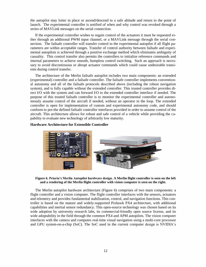
Figure 6. Prioria’s Merlin Autopilot hardware design. A Merlin flight controller is seen on the left
and a rendering of the Merlin flight controller with vision computer is seen on the right.
The Merlin autopilot hardware architecture (Figure 6) comprises of two main components: a
flight controller and a vision computer. The flight controller interfaces with the sensors, actuators
and telemetry and provides fundamental stabilization, control, and navigation functions. This con-
troller is based on the mature and widely-supported Pixhawk PX4 architecture, with additional
capabilities and inertial sensor redundancy. This open-source technology was chosen based on its
wide adoption by university research labs, its commercial-friendly open source license, and its
wide adoptability in the field through the common PX4 and APM autopilots. The vision computer
interfaces with the camera and computes real-time visual navigation using a multi-core processor
and GPU system-on-a-chip (SoC). The SoC used in the current computer design is NVIDIA’s
13
Tegra X1 processor, which contains a 256-core GPU and 8-core, 64-bit ARM® CPU. The main
flight controller and vision computer components communicate over an integrated interface. The
choice of this general purpose embedded extended controller architecture allows the vision pro-
cessor to easily double as the extended controller if desired. The onboard GPU can be leveraged
for accelerating parallel tasks, such as image processing, with CUDA. The extensible hardware
interface provided to the vision computer includes a serial interface directly to the autopilot for
low latency, Ethernet for general purpose, USB 3.0 for high-bandwidth, and S.Bus input for more
direct actuator control.
The extensible software interface is based on the MAVLink open communication protocol.
MAVLink has been adopted in many common system designs including Ardupilot, PX4 and
AR.Drone. MAVLink traditionally provides the communications protocol between a GCS and an
unmanned vehicle, but can also be used for communication between various vehicle subsystems.
The robot operating system (ROS) has also been integrated into the vision computer, providing
the underlying infrastructure for hosting the visual navigation algorithm, camera interfacing, and
image handling processes, in addition to the interface to the failsafe autopilot.
This system architecture provides a robust development and evaluation system for experi-
mental flight controllers, which is capable of ensuring the integrity and safety of the system, even
through many common failures. Any extended controller can easily interface to the vehicle
through the provided hardware ports as long as it conforms to the Prioria-defined interface control
document (ICD) for the hardware and software interfaces. Development of an extended controller
on the embedded X1 co-processor provides an even more efficient and robust path forward for
evaluation of an experimental system.
CONCLUSION
It is currently very challenging to obtain safety approval for experimental flight testing, due to
the inherent dangers in unmanned systems and the current regulatory environment. To facilitate
such safety review processes and ensure range safety, Prioria proposes a novel dual-layer autopi-
lot architecture which augments the experimental controller with a trusted controller. Such a sys-
tem performs in a similar manner to the analogous scenario where an experienced human co-pilot
oversees an unexperienced pilot. This architecture ensures robustness and safety, while allowing
for the advancement of developmental flight control technology. The high-level architecture for
this autopilot system is presented herein. The autopilot system includes a trusted autopilot along
with an experimental (extended) autopilot. Prioria’s trusted autopilot has been designed to include
novel failsafes including the addition of visual odometry for robust navigation and monitoring of
the experimental autopilot. Custom hardware has also been developed to optimally host this auto-
pilot system. The system architecture and initial results are detailed above. Prioria intends to con-
tinue development of this autopilot system and to open source the extensible interface details to
promote the use of this system for future experimental flight testing applications.
ACKNOWLEDGMENTS
Some of the work presented herein represents research which was conducted under NASA con-
tract NNX14CL94C.
The authors wish to acknowledge the significant contributions of the Prioria engineers who are
continuing to develop the Merlin Autopilot. Daniel Agar developed the flight controller software
architecture, including the failsafe mechanisms and external controller interfaces. Devron Lee
designed the flight controller and vision computer hardware. Nate Weibley developed the vision
computer software and configured the vision instrumentation.

14
REFERENCES 1 Poponak, Noah, et al. “Drones: Flying into the Mainstream”. The Goldman Sachs Group, Inc. March 2016. 1-76.
2 Durrant-Whyte, Hugh, and Tim Bailey. "Simultaneous localization and mapping: part I." Robotics & Automation Magazine, IEEE
13.2 (2006): 99-110.
3 Scaramuzza, Davide, and Friedrich Fraundorfer. "Visual odometry [tutorial]." Robotics & Automation Magazine, IEEE 18.4 (2011):
80-92.
4 Honegger, Dominik, et al. "An open source and open hardware embedded metric optical flow cmos camera for indoor and outdoor applications." Robotics and Automation (ICRA), 2013 IEEE International Conference on. IEEE, 2013.
5 Klein, Georg, and David Murray. "Parallel tracking and mapping for small AR workspaces." Mixed and Augmented Reality, 2007.
ISMAR 2007. 6th IEEE and ACM International Symposium on. IEEE, 2007.
6 Blösch, Michael, et al. "Vision based MAV navigation in unknown and unstructured environments." Robotics and automation
(ICRA), 2010 IEEE international conference on. IEEE, 2010.
7 Forster, Christian, Matia Pizzoli, and Davide Scaramuzza. "SVO: Fast semi-direct monocular visual odometry." Robotics and Auto-mation (ICRA), 2014 IEEE International Conference on. IEEE, 2014.