a trial toward sub-100 nm motion error compensation of
TRANSCRIPT
Bulletin of the JSME
Journal of Advanced Mechanical Design, Systems, and ManufacturingVol.15, No.4, 2021
© 2021 The Japan Society of Mechanical Engineers[DOI: 10.1299/jamdsm.2021jamdsm0048]Paper No.20-00503
A trial toward sub-100 nm motion error compensation of
ultra-precision machine tool using on-machine metrology
system with chromatic confocal probe
Hao DUAN*, Shinya MORITA*, Takuya HOSOBATA**, Masahiro TAKEDA**
and Yutaka YAMAGATA**
1. Introduction
In recent years, aspherical optics have been widely used because of their high image quality, compact volume, and
low weight (Fang et al., 2013). General consumer goods, such as mobile phones, cameras, and head-worn displays (Bauer
et al., 2013), as well as state-of-the-art technologies, such as neutron-focusing mirrors (Hosobata et al., 2019) and
aerospace applications, have employed them. However, cutting a high-precision non-axisymmetric optical surface is a
significant challenge in the manufacturing industry. Current multiple-axis ultra-precision machine tools are capable of
precisely machining complex free-form surfaces. However, form errors still remain due to machine motion errors and
the conditions of the machining process. The factors that lead to a decrease in shape accuracy include axis straightness,
scale interpolation errors, thermal deformations, and vibrations. Although it is possible to control or avoid some error
factors, residual errors still need to be reduced or removed using a compensation method (Zhang et al., 2019, Liu, 1999).
One type of form error that is relatively difficult to measure and compensate for is waviness or ripples with a spatial
frequency ranging from 0.1 millimeters to several millimeters. Such errors are called mid-spatial frequency (MSF)
profile errors, and they can affect the performance of various high-precision optical systems (Aikens et al., 2008). Thus,
their removal has been a major focus in optics manufacturing.
An essential step in compensating for these MSF form errors is obtaining the surface profile of the machined
*Tokyo Denki University 5 Senju-asahi-cho, Adachi, Tokyo, 120-8551 Japan
E-mail: [email protected] **RIKEN Center for Advanced Photonics
2-1 Hirosawa, Wako, Saitama, 351-0198 Japan
Received: 30 November 2020; Revised: 1 April 2021; Accepted: 14 June 2021 Abstract Aspherical or free-form optical surface machining using an ultra-precision machine tool is a common and effective method used in the manufacturing of precision optics. However, this method sometimes causes waviness due to mid-spatial frequency (MSF) motion errors of the machine. This waviness lowers the quality of the optical surface. To compensate for the motion error, we use the waviness of the motion error of the axial displacement of an ultra-precision machine tool. This waviness is obtained by a non-contact on-machine metrology (OMM) system that measures an optical flat as a reference. The OMM system consists of a displacement probe and a machine tool axis position capture device. The probe system uses a chromatic confocal probe on an ultra-precision machine tool to evaluate the form deviation of the workpiece with 1-nm resolution. The axis position capture system uses a linear-scale signal branch circuit on each axis of the ultra-precision machine tool. The OMM system is tested in terms of accuracy and repeatability. Through shaper cutting experiments of an oxygen-free copper (OFC) workpiece with feed-forward motion error compensation, we reduce the peak-to-valley (p-v) profile error from 125.3 nm to 42.1 nm.
Keywords : On-machine measurement, Ultra-precision machine tool, Chromatic confocal probe, Feed forward compensation machining, Motion error compensation
1

2© 2021 The Japan Society of Mechanical Engineers[DOI: 10.1299/jamdsm.2021jamdsm0048]
Duan, Morita, Hosobata, Takeda and Yamagata, Journal of Advanced Mechanical Design, Systems, and Manufacturing, Vol.15, No.4 (2021)
workpiece during the compensation process (Jiang 2012, Savio et al.,2007). Commercial metrology devices, such as a
three-dimensional (3D) high-precision profilometer (UA3P, Panasoic Corp.) and laser interferometer (Verifier QPZ,
Zygo Corp.), can measure the MSF error. However, these instruments usually require the removal of the workpiece from
the machine tool, which may introduce a setting error. On-machine metrology (OMM) can prevent such errors (Zhang
et al., 2015). OMM measurements can be performed through many methods, such as line laser displacement sensors
(Abe et al.,2011), atomic force microscopy (Gao et al.,2007), and white-light interferometry (Yan et al., 2007). However,
these methods have limited measurement ranges, accuracies, speeds, or other properties. Recently, a non-contact
measurement method, the chromatic confocal technique, has gained attention because of its high measurement accuracy
and stability (Bai et al., 2019, Tiziani et al., 1994). Chromatic confocal probes are based on the principles of spectroscopy.
The focal point of white light focused by a chromatic dispersive lens differs according to the wavelength. When light is
scattered on the measurement surface, the spectra of the scattered light precisely correspond to the height of the surface.
In our previous studies, we developed an OMM system with an ultra-precision machine tool using a chromatic
confocal probe and an axis position capture system (Duan et al., 2019). The traditional OMM system obtains the axis
position data of the ultra-precision machine tool through the external output of the numerical control (NC) controller. In
this study, the axis position data were divided using the signal branch circuits before the axis position data entered the
NC controller. This method allowed the axis position data to be captured without interfering with the machine control
system. In turn, this reduced the impact of delayed acquisition of the axis position data and allowed the OMM system to
perform high-speed on-machine measurements during multi-axis synchronous control of the ultra-precision machine.
Using this technique, we measured the optical flat and evaluated the stability, positioning accuracy, and repeatability of
the system. The experimental results show that the system had a short-term stability of 1 nm. In addition, the positioning
accuracy of the OMM system for motion on the order of approximately 10 nm was verified in a micro-step motion test,
and repeatability testing demonstrated that it had periodic displacements. The latter are not shape errors of the optical
flat. Rather, they are assumed to be a slight waviness of the motion axis of the ultra-precision machine tool. As a result,
they may cause an MSF error.
In this study, we conduct experiments involving OMM and compensation machining by using captured linear
encoder data of the machine tool with a resolution of approximately 1 nm and a machine tool with precision temperature
control and vibration isolation. The OMM test items included straightness, repeatability evaluation, and probe accuracy
measurements. We used the reference flat to verify the straightness and repeatability of the measurements. Additionally,
the accuracy measurement using the reference sphere simulated the optical devices in the actual measurement. We also
performed a compensation machining experiment for motion errors using the waviness of the motion axis, which was
measured in advance on the optical flat to reduce the waviness of the motion error of the motion axis of the ultra-precision
machine tool. The surface profile accuracy of the machined workpiece was less than 100 nm after the motion error was
compensated for.
2. On-machine metrology system configuration
To verify the possibility of compensating for the motion error with the waviness measurement of the motion axis in
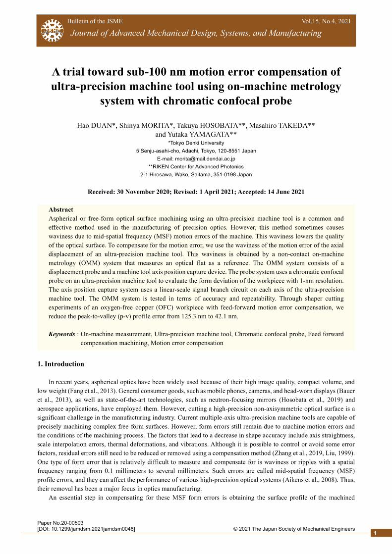
a shaper cutting experiment, a chromatic confocal probe and a single-crystal diamond cutting tool were set on the Y-axis
of the machine tool, as shown in Fig. 1. A diagram of the on-machine measurement system is shown in Fig. 2. The
diamond tool had a radius of 1 mm, and the distance to the probe center was approximately 40 mm. The probe holder
was mounted on the axis of an ultra-precision machine tool (ULG-100D(5A) Shibaura Machine Co. Ltd.), which had
three linear axes (X, Y, and Z) with a V-V roller guide and two rotational axes (B and C). The scale resolution of the
linear axis was 0.1 nm, and the rotational axis resolution was 1/100,000°. During these experiments, the rotational axes
were not used. The machine tool was equipped with a pneumatic vibration isolator and a constant-temperature chamber,
which was maintained at a temperature of 23±0.01 °C.
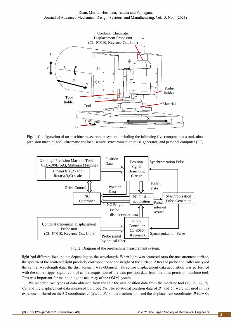
Signal branch circuits on each axis of the ultra-precision machine tool divided the encoder position signal into an
NC controller and a position capture system on a PC. This setup enabled real-time position data capture without
disturbing the machine tool control system. The captured linear encoder data resolution was 1 nm. The chromatic
confocal sensor was composed of a chromatic confocal displacement probe (CL-PT010, Keyence Co., Ltd.) and a probe
controller (CL-3050, Keyence Co., Ltd.). Table 1 lists the specifications of the chromatic confocal sensor, which was
based on the principles of spectroscopy. White light was transmitted from the probe controller to the displacement probe
via the optical fiber. Then the white light was focused by a chromatic dispersive lens in the displacement probe, and the
2
2© 2021 The Japan Society of Mechanical Engineers[DOI: 10.1299/jamdsm.2021jamdsm0048]
Duan, Morita, Hosobata, Takeda and Yamagata, Journal of Advanced Mechanical Design, Systems, and Manufacturing, Vol.15, No.4 (2021)
light had different focal points depending on the wavelength. When light was scattered onto the measurement surface,
the spectra of the scattered light precisely corresponded to the height of the surface. After the probe controller analyzed
the central wavelength data, the displacement was obtained. The sensor displacement data acquisition was performed
with the same trigger signal control as the acquisition of the axis position data from the ultra-precision machine tool.
This was important for maintaining the accuracy of the OMM system.
We recorded two types of data obtained from the PC: the axis position data from the machine tool (XA, YA, ZA, BA,
CA) and the displacement data measured by probe YD. The rotational position data of BA and CA were not used in this
experiment. Based on the 3D coordinates A (XA, YA, ZA) of the machine tool and the displacement coordinates D (0,−YD,
Fig. 1 Configuration of on-machine measurement system, including the following five components: a tool, ultra-
precision machine tool, chromatic confocal sensor, synchronization pulse generator, and personal computer (PC).
X
B
Y C
Tool
Confocal Chromatic
Displacement Probe unit
(CL-PT010, Keyence Co., Ltd.)
Material
Tool
holder
Probe
holder
+−
+
−
Fig. 2 Diagram of the on-machine measurement system.
Probe
Controller
CL-3050
(Keyence)
PC for data
acquisition
NC
Controller
Ultrahigh Precision Machine Tool
(ULG-100D(5A), Shibaura Machine)
Linear(X,Y,Z) and
Rotary(B,C) scale
Position
Data
Synchronization
Pulse GeneratorNC Program
Drive ControlPosition
Data
Position
Signal
Branching
Circuit
Probe
displacement data
Probe signal
by optical fiber
Synchronization Pulse
Synchronization Pulse
Pulse
interval
/count
Confocal Chromatic Displacement
Probe unit
(CL-PT010, Keyence Co., Ltd.)
Position
Data
3
2© 2021 The Japan Society of Mechanical Engineers[DOI: 10.1299/jamdsm.2021jamdsm0048]
Duan, Morita, Hosobata, Takeda and Yamagata, Journal of Advanced Mechanical Design, Systems, and Manufacturing, Vol.15, No.4 (2021)
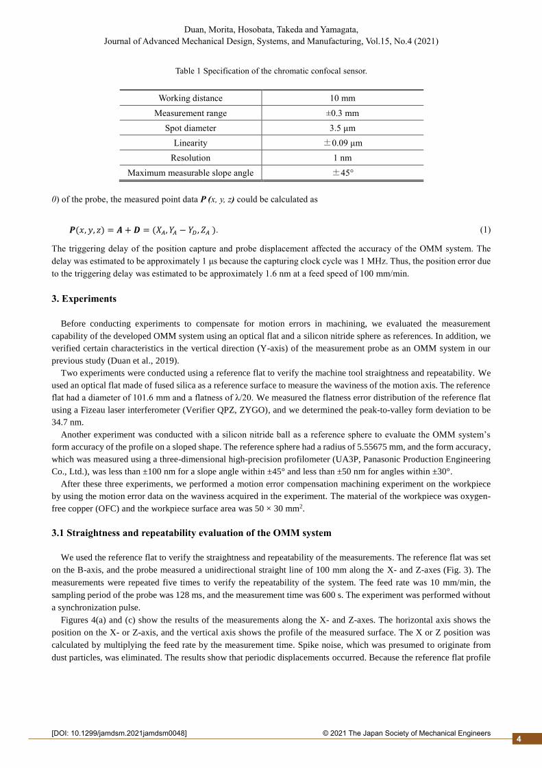
0) of the probe, the measured point data P (x, y, z) could be calculated as
𝑷(𝑥, 𝑦, 𝑧) = 𝑨 + 𝑫 = (𝑋𝐴, 𝑌𝐴 − 𝑌𝐷 , 𝑍𝐴 ). (1)
The triggering delay of the position capture and probe displacement affected the accuracy of the OMM system. The
delay was estimated to be approximately 1 μs because the capturing clock cycle was 1 MHz. Thus, the position error due
to the triggering delay was estimated to be approximately 1.6 nm at a feed speed of 100 mm/min.
3. Experiments
Before conducting experiments to compensate for motion errors in machining, we evaluated the measurement
capability of the developed OMM system using an optical flat and a silicon nitride sphere as references. In addition, we
verified certain characteristics in the vertical direction (Y-axis) of the measurement probe as an OMM system in our
previous study (Duan et al., 2019).
Two experiments were conducted using a reference flat to verify the machine tool straightness and repeatability. We
used an optical flat made of fused silica as a reference surface to measure the waviness of the motion axis. The reference
flat had a diameter of 101.6 mm and a flatness of λ/20. We measured the flatness error distribution of the reference flat
using a Fizeau laser interferometer (Verifier QPZ, ZYGO), and we determined the peak-to-valley form deviation to be
34.7 nm.
Another experiment was conducted with a silicon nitride ball as a reference sphere to evaluate the OMM system’s
form accuracy of the profile on a sloped shape. The reference sphere had a radius of 5.55675 mm, and the form accuracy,
which was measured using a three-dimensional high-precision profilometer (UA3P, Panasonic Production Engineering
Co., Ltd.), was less than ±100 nm for a slope angle within ±45° and less than ±50 nm for angles within ±30°.
After these three experiments, we performed a motion error compensation machining experiment on the workpiece
by using the motion error data on the waviness acquired in the experiment. The material of the workpiece was oxygen-
free copper (OFC) and the workpiece surface area was 50 × 30 mm2.
3.1 Straightness and repeatability evaluation of the OMM system
We used the reference flat to verify the straightness and repeatability of the measurements. The reference flat was set
on the B-axis, and the probe measured a unidirectional straight line of 100 mm along the X- and Z-axes (Fig. 3). The
measurements were repeated five times to verify the repeatability of the system. The feed rate was 10 mm/min, the
sampling period of the probe was 128 ms, and the measurement time was 600 s. The experiment was performed without
a synchronization pulse.
Figures 4(a) and (c) show the results of the measurements along the X- and Z-axes. The horizontal axis shows the
position on the X- or Z-axis, and the vertical axis shows the profile of the measured surface. The X or Z position was
calculated by multiplying the feed rate by the measurement time. Spike noise, which was presumed to originate from
dust particles, was eliminated. The results show that periodic displacements occurred. Because the reference flat profile
Table 1 Specification of the chromatic confocal sensor.
Working distance 10 mm
Measurement range ±0.3 mm
Spot diameter 3.5 μm
Linearity ±0.09 μm
Resolution 1 nm
Maximum measurable slope angle ±45°
4

2© 2021 The Japan Society of Mechanical Engineers[DOI: 10.1299/jamdsm.2021jamdsm0048]
Duan, Morita, Hosobata, Takeda and Yamagata, Journal of Advanced Mechanical Design, Systems, and Manufacturing, Vol.15, No.4 (2021)
Duan, Morita, Hosobata, Takeda and Yamagata, Journal of Advanced Mechanical Design, Systems, and Manufacturing, Vol.15, No.4 (2021)
did not include such periodic displacements, they were likely due to the waviness of the axis straightness of the machine
Fig. 3 Straightness and repeatability evaluation on optical flat. The reference flat diameter was 101.6 mm, the
flatness was 31.64 nm (λ/20, where λ = 632.8 nm), and the feed rate was 10 mm/min.
Fig. 4 Straightness and repeatability evaluation of the OMM system results using reference flat. The feed rate was 10 mm/min and the data sampling period was 20 ms.
5

2© 2021 The Japan Society of Mechanical Engineers[DOI: 10.1299/jamdsm.2021jamdsm0048]
Duan, Morita, Hosobata, Takeda and Yamagata, Journal of Advanced Mechanical Design, Systems, and Manufacturing, Vol.15, No.4 (2021)
tool. To quantify the repeatability of the OMM system, the five measurements were averaged, and the average value was
subtracted from each of the five individual measurements. The deviation results are shown in Figs. 4(b) and (d). The
overall repeatability of the measurements was ±5 nm for a 100-mm displacement along the X-axis, although there was
a waviness of approximately ±30 nm in the straightness. The waviness was approximately 40 nm in the Z-axis
straightness, and the overall repeatability of the measurements was less than ±10 nm. To evaluate the repeatability of the
experiment, the standard deviation (σ) accounted for the first to the fifth measurements in the direction of the X- or Z-
axes. The standard deviation of the repeatability was 1.8 nm for the X-axis and 5.3 nm for the Z-axis. Moreover, the
cause of the waviness observed in the optical flat measurements may have been the roundness error of the rollers or the
minute waviness of the guiding surface, or both. However, because the V-V roller guide system adopted non-circulating
rollers, there was probably a high repeatability in the straightness error. Therefore, it is important to verify the
repeatability of this straightness error during the long-term operation of an ultra-precision machine tool.
3.2 Straightness and repeatability evaluation at different feed rates
To test the straightness and repeatability of the waviness at different feed rates, we used the same optical flat and
method as in Section 3.1. However, the feed rates were slightly different, and the experiment was carried out using
synchronization pulses with a sampling period of 20 ms. The feed rates of the X-axis were 10, 20, 50, 100, 200 and
500 mm/min, with a range of ±50 mm. The feed rates of the Z-axis were 5, 10, 20, 50, 100, 200, and 500 mm/min, with
a range of ±25 mm. Figure 5(a) shows the results for the X-axis, and Fig. 5(b) shows the results for the Z-axis. A low-
pass filter was applied to the profile data to eliminate high-frequency noise. These results shows that the waviness and
σ were repeatable and that they did not depend on the feed rate from 10 to 500 mm/min. This suggests the possibility of
1
(a) Changes in the feed-rate on the X-axis, with a low-pass filter cutoff frequency of 10 mm-1.
(b) Changes in the feed-rate on the Z-axis, with a low-pass filter cutoff frequency of 10 mm-1.
Fig. 5 Straightness and repeatability evaluation of the optical flat using the OMM system. The feed rates were 10,
20, 50, 100, 200 and 500 mm/min and the data sampling period was 20 ms.
σ:18.2 nm
σ:18.1 nm
σ:17.5 nm
σ:17.4 nm
σ:17.6 nm
σ:16.5 nm
σ:18.4 nm
σ:19.9 nm
σ:20.6 nm
σ:20.9 nm
σ:21.0 nm
σ:20.4 nm
σ:20.5 nm
6
2© 2021 The Japan Society of Mechanical Engineers[DOI: 10.1299/jamdsm.2021jamdsm0048]
Duan, Morita, Hosobata, Takeda and Yamagata, Journal of Advanced Mechanical Design, Systems, and Manufacturing, Vol.15, No.4 (2021)
compensating for feed-forward motion error.
3.3 Form accuracy verification of the OMM system
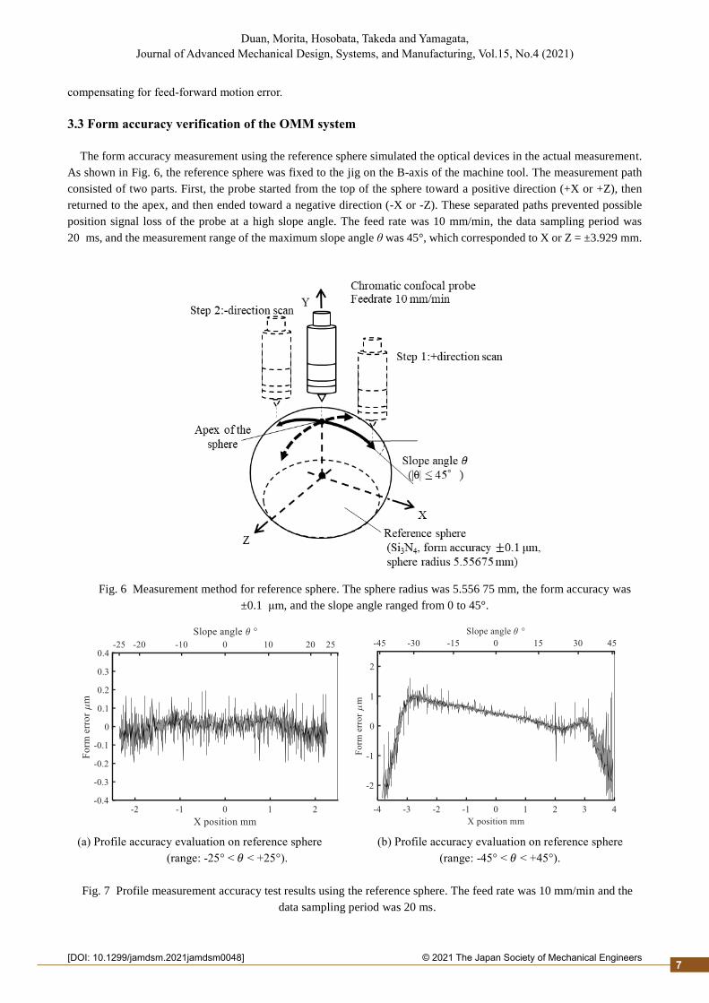
The form accuracy measurement using the reference sphere simulated the optical devices in the actual measurement.
As shown in Fig. 6, the reference sphere was fixed to the jig on the B-axis of the machine tool. The measurement path
consisted of two parts. First, the probe started from the top of the sphere toward a positive direction (+X or +Z), then
returned to the apex, and then ended toward a negative direction (-X or -Z). These separated paths prevented possible
position signal loss of the probe at a high slope angle. The feed rate was 10 mm/min, the data sampling period was
20 ms, and the measurement range of the maximum slope angle θ was 45°, which corresponded to X or Z = ±3.929 mm.
(a) Profile accuracy evaluation on reference sphere (b) Profile accuracy evaluation on reference sphere
(range: -25° < 𝜃 < +25°). (range: -45° < 𝜃 < +45°).
Fig. 7 Profile measurement accuracy test results using the reference sphere. The feed rate was 10 mm/min and the
data sampling period was 20 ms.
Fig. 6 Measurement method for reference sphere. The sphere radius was 5.556 75 mm, the form accuracy was
±0.1 μm, and the slope angle ranged from 0 to 45°.
7
2© 2021 The Japan Society of Mechanical Engineers[DOI: 10.1299/jamdsm.2021jamdsm0048]
Duan, Morita, Hosobata, Takeda and Yamagata, Journal of Advanced Mechanical Design, Systems, and Manufacturing, Vol.15, No.4 (2021)
Duan, Morita, Hosobata, Takeda and Yamagata, Journal of Advanced Mechanical Design, Systems, and Manufacturing, Vol.15, No.4 (2021)
The shape data were fitted to the reference sphere using the least squares method on the radius of the reference sphere, and the residual errors were obtained.
Figure 7(a) shows the measurement results for the reference sphere with a range of ±25°, which corresponds to X or Z = ±2.348 mm. The profile error of this region was well within ±100 nm. The root mean square (RMS) error was approximately 150.0 nm for the Z-axis and 57.0 nm for the X-axis. The results were better when the X- and Y-axes were used for the measurement than when the Z- and Y-axes were used. This was due to the fact that the probe was influenced by only vertical movement when the X- and Y-axes were used for the measurement, while the Z- and Y-axes were influenced by both horizontal and vertical movements.
Figure 7(b) shows the profile error measured along the X-axis. Except for the spike, which was likely caused by a dust particle or a pit in the ceramic material, the profile error amplitude increased as the X position approached ±3.929 mm. The increase in the slope angle during the accuracy measurement of the reference sphere using the OMM system caused a profile error in the measurement results. When the least squares method was used to perform the spherical shape fitting with the measurement results containing the profile error, the radius of the fit was changed, and the shape error results were distorted. The reason for the increase in noise may have been due to a reduction in scattered light intensity at high slope angles and the fact that the profile error trend changed at a slope angle of 30º. These results indicate that the chromatic confocal probe was not capable of maintaining the measurement accuracy for slope angles larger than 30°. Thus, the estimated measurement accuracy of this OMM system was approximately 100 nm within a slope angle of ±25°.
3.4 Feed-forward motion error compensation
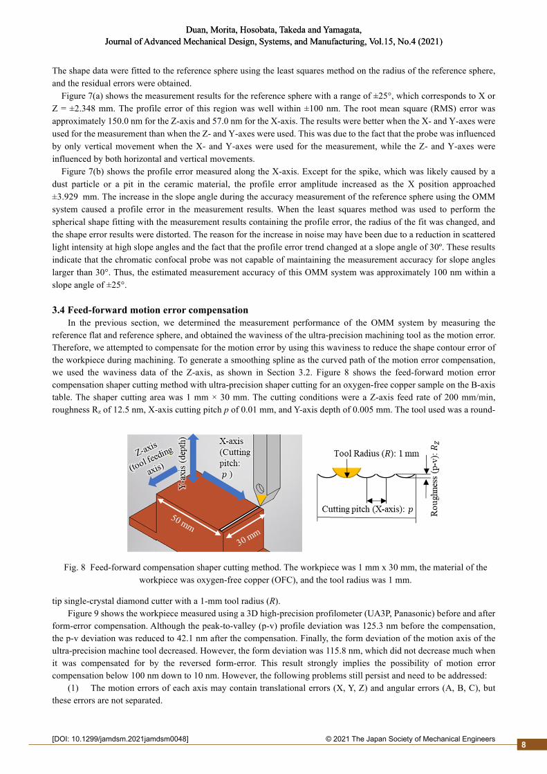
In the previous section, we determined the measurement performance of the OMM system by measuring the reference flat and reference sphere, and obtained the waviness of the ultra-precision machining tool as the motion error. Therefore, we attempted to compensate for the motion error by using this waviness to reduce the shape contour error of the workpiece during machining. To generate a smoothing spline as the curved path of the motion error compensation, we used the waviness data of the Z-axis, as shown in Section 3.2. Figure 8 shows the feed-forward motion error compensation shaper cutting method with ultra-precision shaper cutting for an oxygen-free copper sample on the B-axis table. The shaper cutting area was 1 mm × 30 mm. The cutting conditions were a Z-axis feed rate of 200 mm/min, roughness Rz of 12.5 nm, X-axis cutting pitch p of 0.01 mm, and Y-axis depth of 0.005 mm. The tool used was a round-
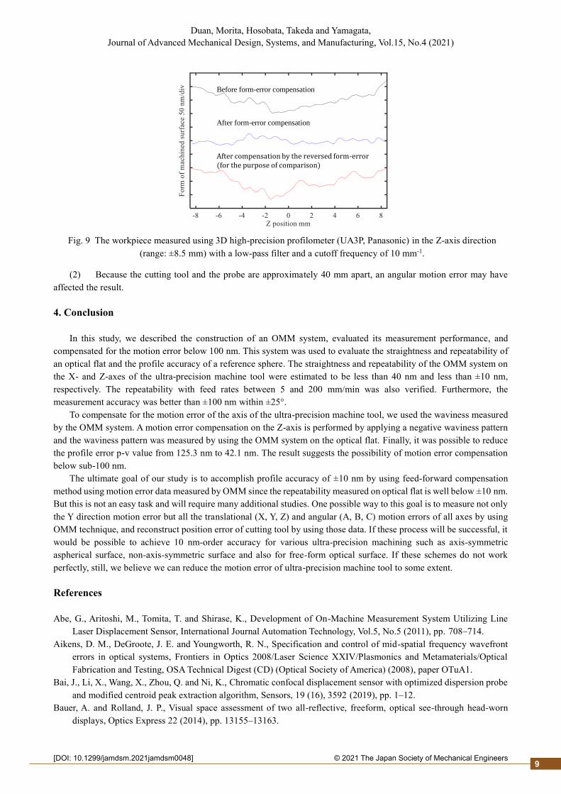
tip single-crystal diamond cutter with a 1-mm tool radius (R). Figure 9 shows the workpiece measured using a 3D high-precision profilometer (UA3P, Panasonic) before and after
form-error compensation. Although the peak-to-valley (p-v) profile deviation was 125.3 nm before the compensation, the p-v deviation was reduced to 42.1 nm after the compensation. Finally, the form deviation of the motion axis of the ultra-precision machine tool decreased. However, the form deviation was 115.8 nm, which did not decrease much when it was compensated for by the reversed form-error. This result strongly implies the possibility of motion error compensation below 100 nm down to 10 nm. However, the following problems still persist and need to be addressed:
(1) The motion errors of each axis may contain translational errors (X, Y, Z) and angular errors (A, B, C), but these errors are not separated.
Fig. 8 Feed-forward compensation shaper cutting method. The workpiece was 1 mm x 30 mm, the material of the workpiece was oxygen-free copper (OFC), and the tool radius was 1 mm.
8
2© 2021 The Japan Society of Mechanical Engineers[DOI: 10.1299/jamdsm.2021jamdsm0048]
Duan, Morita, Hosobata, Takeda and Yamagata, Journal of Advanced Mechanical Design, Systems, and Manufacturing, Vol.15, No.4 (2021)
(2) Because the cutting tool and the probe are approximately 40 mm apart, an angular motion error may have
affected the result.
4. Conclusion
In this study, we described the construction of an OMM system, evaluated its measurement performance, and
compensated for the motion error below 100 nm. This system was used to evaluate the straightness and repeatability of
an optical flat and the profile accuracy of a reference sphere. The straightness and repeatability of the OMM system on
the X- and Z-axes of the ultra-precision machine tool were estimated to be less than 40 nm and less than ±10 nm,
respectively. The repeatability with feed rates between 5 and 200 mm/min was also verified. Furthermore, the
measurement accuracy was better than ±100 nm within ±25°.
To compensate for the motion error of the axis of the ultra-precision machine tool, we used the waviness measured
by the OMM system. A motion error compensation on the Z-axis is performed by applying a negative waviness pattern
and the waviness pattern was measured by using the OMM system on the optical flat. Finally, it was possible to reduce
the profile error p-v value from 125.3 nm to 42.1 nm. The result suggests the possibility of motion error compensation
below sub-100 nm.
The ultimate goal of our study is to accomplish profile accuracy of ±10 nm by using feed-forward compensation
method using motion error data measured by OMM since the repeatability measured on optical flat is well below ±10 nm.
But this is not an easy task and will require many additional studies. One possible way to this goal is to measure not only
the Y direction motion error but all the translational (X, Y, Z) and angular (A, B, C) motion errors of all axes by using
OMM technique, and reconstruct position error of cutting tool by using those data. If these process will be successful, it
would be possible to achieve 10 nm-order accuracy for various ultra-precision machining such as axis-symmetric
aspherical surface, non-axis-symmetric surface and also for free-form optical surface. If these schemes do not work
perfectly, still, we believe we can reduce the motion error of ultra-precision machine tool to some extent.
References
Abe, G., Aritoshi, M., Tomita, T. and Shirase, K., Development of On-Machine Measurement System Utilizing Line
Laser Displacement Sensor, International Journal Automation Technology, Vol.5, No.5 (2011), pp. 708–714.
Aikens, D. M., DeGroote, J. E. and Youngworth, R. N., Specification and control of mid-spatial frequency wavefront
errors in optical systems, Frontiers in Optics 2008/Laser Science XXIV/Plasmonics and Metamaterials/Optical
Fabrication and Testing, OSA Technical Digest (CD) (Optical Society of America) (2008), paper OTuA1.
Bai, J., Li, X., Wang, X., Zhou, Q. and Ni, K., Chromatic confocal displacement sensor with optimized dispersion probe
and modified centroid peak extraction algorithm, Sensors, 19 (16), 3592 (2019), pp. 1–12.
Bauer, A. and Rolland, J. P., Visual space assessment of two all-reflective, freeform, optical see-through head-worn
displays, Optics Express 22 (2014), pp. 13155–13163.
Fig. 9 The workpiece measured using 3D high-precision profilometer (UA3P, Panasonic) in the Z-axis direction
(range: ±8.5 mm) with a low-pass filter and a cutoff frequency of 10 mm-1.
After compensation by the reversed form-error (for the purpose of comparison)
After form-error compensation
Before form-error compensation
9

2© 2021 The Japan Society of Mechanical Engineers[DOI: 10.1299/jamdsm.2021jamdsm0048]
Duan, Morita, Hosobata, Takeda and Yamagata, Journal of Advanced Mechanical Design, Systems, and Manufacturing, Vol.15, No.4 (2021)
Duan, H., Morita, S., Hosobata, T., Takeda, M. and Yamagata, Y., On-machine measurement of ultra-precision machine
tool using confocal chromatic probe, ABTEC (Abrasive Technology Conference) (2019), pp. 108–113 (in
Japanese).
Fang, F., Zhang, X., Weckenmann, A., Zhang, G. and Evans, C.J., Manufacturing and measurement of freeform optics,
CIRP Annals 62 (2) (2013), pp. 823–846.
Gao, W., Aoki, J., Ju, B.-F. and Kiyono, S., Surface profile measurement of a sinusoidal grid using an atomic force
microscope on a diamond turning machine, Precision Engineering 31 (2007), pp. 304–309.
Hosobata, T., Yamada, N.L., Hino, M., Yoshinaga, H., Nemoto, F., Hori, K., Kawai, T., Yamagata, Y., Takeda, M. and
Takeda, S., Elliptic neutron-focusing supermirror for illuminating small samples in neutron reflectometry, Optics
Express 27 (2019), pp. 26807–26820.
Jiang, X., Precision surface measurement, Philosophical Transactions of the Royal Society A: Mathematical, Physical
and Engineering Sciences 370 (2012), pp. 4089–4114.
Liu, Z.-Q., Repetitive measurement and compensation to improve workpiece machining accuracy, International Journal
of Advanced Manufacturing Technology 15 (1999), pp. 85–89.
Savio, E., De Chiffre, L. and Schmitt, R.H., Metrology of freeform shaped parts, CIRP Annals 56 (2) (2007), pp. 810–
835.
Tiziani, H.J. and Uhde, H.-M. , Three-dimensional image sensing by chromatic confocal microscopy, Applied Optics 33
(1994), pp. 1838–1843.
Yan, J., Baba, H., Kunieda, Y., Yoshihara, N. and Kuriyagawa, T., Nano precision on-machine profiling of curved
diamond cutting tools using a white-light interferometer, International Journal Surface Science and Engineering,
Vol.1, No.4 (2007), pp. 441–455.
Zhang, X., Zeng, Z., Liu, X. and Fang, F., Development of On-Machine Measurement System Utilizing Line Laser
Displacement Sensor, Optics Express 23 (19) (2015), pp. 24800–24810.
Zhang, Z., Yan, J. and Kuriyagawa, T., Manufacturing technologies toward extreme precision, International Journal of
Extreme Manufacturing, 1 022001 (2019), pp. 1–22.
10