a tpm-enabled remote attestation protocol (trap) in
TRANSCRIPT
A TPM-enabled Remote Attestation Protocol (TRAP) inWireless Sensor Networks
Hailun TanSchool of Computer Science
and Engineeringthe University of New South
Wen HuICT Centre
Sanjay JhaSchool of Computer Science
and Engineeringthe University of New South
ABSTRACTGiven the limited resources and computational power of cur-rent embedded sensor devices, memory protection is diffi-cult to achieve and generally unavailable. Hence, the soft-ware run-time buffer overflow that is used by the worm at-tacks in the Internet could be easily exploited to inject ma-licious codes into Wireless Sensor Networks (WSNs). Previ-ous software-based remote code verification approaches suchas SWATT and SCUBA have been shown difficult to deployin recent work. In this paper, we propose and implement aremote attestation protocol for detecting unauthorized tam-pering in the application codes running on sensor nodes withthe assistance of Trusted Platform Modules (TPMs), thetiny, cost-effective and tamper-proof cryptographic micro-controllers. In our design, each sensor node is equippedwith a TPM and the firmware running on the node couldbe verified by the other sensor nodes in a WSN, includingthe sink. Specifically, we present a hardware-based remoteattestation protocol, discuss the potential attacks an adver-sary could launch against the protocol, and provide com-prehensive system performance results of the protocol in amulti-hop sensor network testbed.
Categories and Subject DescriptorsC.2.2 [Computer-Communication Networks]: NetworkProtocols; D.4.6 [Operating Systems]: Security and Pro-tection
General TermsSecurity
Keywordsremote attestation, Trusted Platform Module, Wireless Sen-sor Networks
1. INTRODUCTIONCurrent research on security for Wireless Sensor Networks
(WSNs) focuses on attacks such as communication channel
Permission to make digital or hard copies of all or part of this work forpersonal or classroom use is granted without fee provided that copies arenot made or distributed for profit or commercial advantage and that copiesbear this notice and the full citation on the first page. To copy otherwise, torepublish, to post on servers or to redistribute to lists, requires prior specificpermission and/or a fee.MSWiM’11, Miami Beach, FL, USACopyright 20XX ACM X-XXXXX-XX-X/XX/XX ...$10.00.
jamming [1], countering attacks on routing protocols [2] andproviding attack-resistant code dissemination [3]. A typeof potentially more severe attacks called sensor worm at-tacks has yet to be fully studied. In sensor worm attacks,an attacker would first attempt to discover an exploitablesoftware vulnerability, for example by examining a physi-cally captured sensor node. These software vulnerabilitiesare commonly found in popular sensor network operatingsystem libraries such as TinyOS [4, 5]. By exploiting thevulnerabilities and the popular features such as over-the-air-programming [6] enabled by bootloader, the attacker canthen inject packets carrying the malicious codes into the net-works. Hence, a malicious program could hijack executionby injecting itself into the program memory of a node andself-propagate to other nodes by a buffer overflow event [4,7, 8], which will be further explained in Section 2.1.
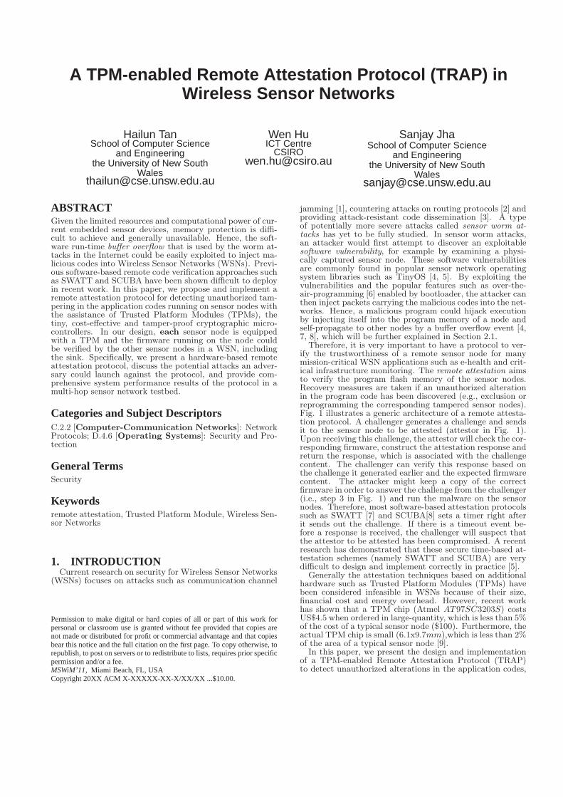
Therefore, it is very important to have a protocol to ver-ify the trustworthiness of a remote sensor node for manymission-critical WSN applications such as e-health and crit-ical infrastructure monitoring. The remote attestation aimsto verify the program flash memory of the sensor nodes.Recovery measures are taken if an unauthorized alterationin the program code has been discovered (e.g., exclusion orreprogramming the corresponding tampered sensor nodes).Fig. 1 illustrates a generic architecture of a remote attesta-tion protocol. A challenger generates a challenge and sendsit to the sensor node to be attested (attestor in Fig. 1).Upon receiving this challenge, the attestor will check the cor-responding firmware, construct the attestation response andreturn the response, which is associated with the challengecontent. The challenger can verify this response based onthe challenge it generated earlier and the expected firmwarecontent. The attacker might keep a copy of the correctfirmware in order to answer the challenge from the challenger(i.e., step 3 in Fig. 1) and run the malware on the sensornodes. Therefore, most software-based attestation protocolssuch as SWATT [7] and SCUBA[8] sets a timer right afterit sends out the challenge. If there is a timeout event be-fore a response is received, the challenger will suspect thatthe attestor to be attested has been compromised. A recentresearch has demonstrated that these secure time-based at-testation schemes (namely SWATT and SCUBA) are verydifficult to design and implement correctly in practice [5].
Generally the attestation techniques based on additionalhardware such as Trusted Platform Modules (TPMs) havebeen considered infeasible in WSNs because of their size,financial cost and energy overhead. However, recent workhas shown that a TPM chip (Atmel AT97SC3203S) costsUS$4.5 when ordered in large-quantity, which is less than 5%of the cost of a typical sensor node ($100). Furthermore, theactual TPM chip is small (6.1x9.7mm),which is less than 2%of the area of a typical sensor node [9].
In this paper, we present the design and implementationof a TPM-enabled Remote Attestation Protocol (TRAP)to detect unauthorized alterations in the application codes,
Attestation
protocol
1. Compute
the challenge
2. ChallengeAttestation
protocol
5. Attestation response
6. Response
verification
firmware
3. Check
firmware
4. Compute
response
challenger attestor
Figure 1: The architectural overview of remote at-testation protocol: the numbers represent the tem-poral ordering of events.
particularly due to sensor worm attacks in the Harvard-architecture-based sensor nodes. Since Harvard architec-ture micro-controllers are commonly used in the WSNs (e.g.,the Mica family motes manufactured by Crossbow), TRAPcould be widely adopted in many mission-critical WSN ap-plications. Our evaluation results based on a multi-hoptestbed show that the energy consumption, attestation la-tency, and code size of TRAP are viable in the WSNs.
The contributions of this paper include:
• A new approach for remote attestation in Harvard-architecture-based embedded devices: most ofthe previous work addressing remote attestation inWSNs is software-based [10, 7, 8, 11]. It typicallyassumes that sensor nodes do not incorporate extrasecurity hardware. Therefore, these software-based ap-proaches depend on the strict response time measure-ment to ensure that the correct attestation responsesare not forged by the attackers. Recent research hasshown that these software-based attestation protocolscould be beaten by generating the correct attestationresponse quicker than expected [5]. Though some ofthe previous approaches adopt TPM to detect nodecompromise, the TPM is used for the cluster head onlyrather than each sensor node leading to only the clus-ter heads being attested [12].
• New countermeasures against TPM-related at-tacks: because of the severe resource constraints inWSNs, some TPM-related attacks (e.g., TPM resetattacks [13]) that can be defended against in PCs willpose a threat in the sensor nodes equipped with TPM.In TRAP, these attacks are studied and tackled withthe new countermeasures as discussed in Section 4.
The rest of this paper is organized as follows. The attackermodel, background and our assumptions are presented inSection 2. The design and implementation of TRAP is de-scribed in Section 3, followed by the security analysis inSection 4, and the respective performance evaluation in Sec-tion 5. The related work is surveyed in Section 6 and thepaper is concluded in Section 7.
2. ATTACKER MODEL, BACKGROUND ANDASSUMPTIONS
2.1 Attacker ModelIn this paper, an attacker is able to inject the malicious
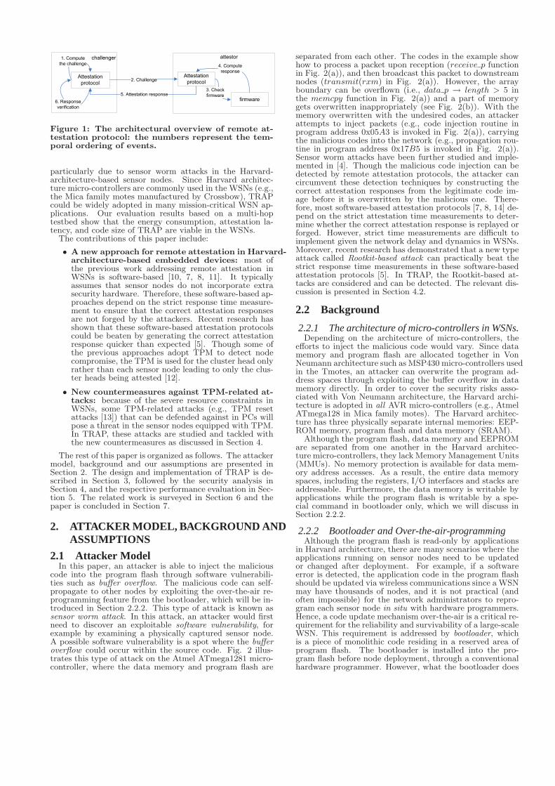
code into the program flash through software vulnerabili-ties such as buffer overflow. The malicious code can self-propagate to other nodes by exploiting the over-the-air re-programming feature from the bootloader, which will be in-troduced in Section 2.2.2. This type of attack is known assensor worm attack. In this attack, an attacker would firstneed to discover an exploitable software vulnerability, forexample by examining a physically captured sensor node.A possible software vulnerability is a spot where the bufferoverflow could occur within the source code. Fig. 2 illus-trates this type of attack on the Atmel ATmega1281 micro-controller, where the data memory and program flash are
separated from each other. The codes in the example showhow to process a packet upon reception (receive p functionin Fig. 2(a)), and then broadcast this packet to downstreamnodes (transmit(rxm) in Fig. 2(a)). However, the arrayboundary can be overflown (i.e., data p → length > 5 inthe memcpy function in Fig. 2(a)) and a part of memorygets overwritten inappropriately (see Fig. 2(b)). With thememory overwritten with the undesired codes, an attackerattempts to inject packets (e.g., code injection routine inprogram address 0x05A3 is invoked in Fig. 2(a)), carryingthe malicious codes into the network (e.g., propagation rou-tine in program address 0x17B5 is invoked in Fig. 2(a)).Sensor worm attacks have been further studied and imple-mented in [4]. Though the malicious code injection can bedetected by remote attestation protocols, the attacker cancircumvent these detection techniques by constructing thecorrect attestation responses from the legitimate code im-age before it is overwritten by the malicious one. There-fore, most software-based attestation protocols [7, 8, 14] de-pend on the strict attestation time measurements to deter-mine whether the correct attestation response is replayed orforged. However, strict time measurements are difficult toimplement given the network delay and dynamics in WSNs.Moreover, recent research has demonstrated that a new typeattack called Rootkit-based attack can practically beat thestrict response time measurements in these software-basedattestation protocols [5]. In TRAP, the Rootkit-based at-tacks are considered and can be detected. The relevant dis-cussion is presented in Section 4.2.
2.2 Background
2.2.1 The architecture of micro-controllers in WSNs.Depending on the architecture of micro-controllers, the
efforts to inject the malicious code would vary. Since datamemory and program flash are allocated together in VonNeumann architecture such as MSP430 micro-controllers usedin the Tmotes, an attacker can overwrite the program ad-dress spaces through exploiting the buffer overflow in datamemory directly. In order to cover the security risks asso-ciated with Von Neumann architecture, the Harvard archi-tecture is adopted in all AVR micro-controllers (e.g., AtmelATmega128 in Mica family motes). The Harvard architec-ture has three physically separate internal memories: EEP-ROM memory, program flash and data memory (SRAM).
Although the program flash, data memory and EEPROMare separated from one another in the Harvard architec-ture micro-controllers, they lack Memory Management Units(MMUs). No memory protection is available for data mem-ory address accesses. As a result, the entire data memoryspaces, including the registers, I/O interfaces and stacks areaddressable. Furthermore, the data memory is writable byapplications while the program flash is writable by a spe-cial command in bootloader only, which we will discuss inSection 2.2.2.
2.2.2 Bootloader and Over-the-air-programmingAlthough the program flash is read-only by applications
in Harvard architecture, there are many scenarios where theapplications running on sensor nodes need to be updatedor changed after deployment. For example, if a softwareerror is detected, the application code in the program flashshould be updated via wireless communications since a WSNmay have thousands of nodes, and it is not practical (andoften impossible) for the network administrators to repro-gram each sensor node in situ with hardware programmers.Hence, a code update mechanism over-the-air is a critical re-quirement for the reliability and survivability of a large-scaleWSN. This requirement is addressed by bootloader, whichis a piece of monolithic code residing in a reserved area ofprogram flash. The bootloader is installed into the pro-gram flash before node deployment, through a conventionalhardware programmer. However, what the bootloader does

pop %ds�
xchg %eax, %ebx�.
Code Injection Routinepop %ds�
mov $0x572A, %ebp�
Boot Flash
0x0000
0x05A3
0x17B5
32 registers
64 I/O registers
160 Ext I/O registers
Global VariablesInternal SRAM (8192 bytes)
stack
0x0000
0x001F0x00200x005F0x00600x00FF0x0100
0x20FF0x2100 External Flash
0xFFFF
Stack Pointer
pop %ds�
xchg %eax, %ebx�.
Code Injection Routinepop %ds�
mov $0x572A, %ebp�
Boot Flash
0x0000
0x05A3
0x17B5
32 registers
64 I/O registers
160 Ext I/O registers
Global VariablesInternal SRAM (8192 bytes)
stack
0x0000
0x001F0x00200x005F0x00600x00FF0x0100
0x20FF0x2100 External Flash
0xFFFF
Application Flash
Propagation Routinepop %ds�
xchg %eax, %ebx�.
Code Injection Routinepop %ds�
mov $0x572A, %ebp�
Boot Flash
0x0000
0x05A3
0x17B5
32 registers
64 I/O registers
160 Ext I/O registers
32 registers
64 I/O registers
160 Ext I/O registers
Global VariablesInternal SRAM (8192 bytes)
stack
0x0000
0x001F0x00200x005F0x00600x00FF0x0100
0x20FF0x2100 External Flash
0xFFFF
typedef struct Packet {
�
uint16_t length;
uint8_t *payload;
} pkt_t;
Message_t *receive_p (Message_t *rxm)
{
uint8_t buffer[5];
pkt_t *data_p = (pkt_t *) rxm->data;
//buffer overflow occurs here
memcpy(buffer,
data_p->payload, data_p->length);
process_packet (buffer);
transmit (rxm);
�
return rxm;
}
Code injection address = 0x05A3
Propagation address= 0x17B5
(a) C code to be exploited in sensor application and thecorresponding memory allocations.
uint8_t payload[] = {
0x00, 0x01, 0x02,0x03, 0x04, //fill the buffer
0x05, 0xA3, //program address to copy malware
0x57, 0x2A, //address to place malware
MALWARE DATA,
0x00, //padding
0x17, 0xB5, //program address to propagate malware
�
0x00, 0x00 // reboot the sensor node
}
(b) Packet payload to inject the malicious code.
Figure 2: A buffer overflow example on memory structure of Atmel ATmega1281 micro-controllers (Harvardarchitecture).
here is different from any conventional application. Onceinstalled, the bootloader will start to listen to the incomingmessages through the radio interface to obtain the applica-tion update, and store them in the external flash given thelimited size of program memory. After a complete applica-tion update is received, it is copied from the external flash todata memory, and the bootloader could transfer the appli-cation update from data memory to program flash throughStore to Program Memory (SPM) command in the AVR as-sembly language. The sensor node starts to execute the newapplication code after reboot, triggered by the bootloader.Therefore, it is possible for an attacker to exploit the self-programming routine in the bootloader so that the maliciouscodes can be copied from the data memory to program flash[4].
2.3 AssumptionsIn this paper, we assume that an attacker could not phys-
ically compromise a large number of sensor nodes in a large-scale deployment given that it would require the attackerwith hardware (e.g., a PC or laptop with JTAG) to be physi-cally present in the deployment region for a long time. Thisincreases the attacker’s risks of being detected. However,we assume that the attacker could physically capture a smallnumber of sensor nodes through the use of a PC-class deviceand some dedicated, specialized hardware such as JTAG [15]equipment. Consequently, software vulnerabilities in the ap-plication code may be discovered by the attacker. Malwareis assumed to be self-propagating (i.e., after installation, acontaminated node can invoke the code injection routine topropagate the code image to its downstream peers). In thisway, the attacker could compromise the whole network byphysically capturing a few sensor nodes only.
The code injection routine is one of the functionalities ofthe bootloader. Henceforth, we assume that each sensor nodeis configured with a bootloader. This assumption is realis-tic given the requirement for the over-the-air code updatemechanism described in Section 2.2.2.
Finally, we assume that bootloader could not be over-written over-the-air by setting the relevant bootloader lockbits in the microcontrollers (e.g., Boot lock bit 1 in Atmega128) before deployment. This is a realistic assumption be-cause the bootloader is single-purpose (e.g., receive a newversion of application program over-the-air and copy it tothe program flash) and small (less than 8 KB in Atmega128). Therefore, the bootloader typically is not required tobe updated remotely once WSNs are deployed.
3. TPM-ENABLED REMOTE ATTESTATIONPROTOCOL (TRAP)
3.1 Trusted Platform Module BasicsA TPM is a tamper-proof hardware based on the Trusted
Computing specification [16]. The objective of a TPM isto provide a hardware-based root of trust for a computingsystem. The TPM board used in our experiment is equippedwith Atmel AT97SC3203S TPM chip [17]. In our design,several TPM commands would be used. According to thesecurity levels, they are categorized as either unauthorized
commands or authorized commands1:
• unauthorized commands are those which could be ex-ecuted without authorization as long as the commandformat complies the standard of Trusted Computing[16]. They do not require the input nonce to gener-ate the outputs. The unauthorized TPM commandsused in TRAP are TPM Startup, TPM GetRandom,TPM Hash, TPM Turnoff TPM PcrExtendTPM V erifySignature.
• authorized commands are those which require certainauthorization before they could be executed. An inputnonce is required. There will be an output nonce, a 20-byte HMAC (Hashed Message Authentication Code)result as authorization digest, together with outputresults. The authorization digest is derived from theinput nonce, output nonce and the output results. Thenonces are used to ensure the output results are gen-erated from a genuine TPM and they could not bereplayed by the authorization digest verification. Theauthorized commands used in TRAP are TPM Loadkey,TPM NV Define, TPM NV WriteV alue, TPM Seal,TPM Unseal, TPM Sign, TPM NV ReadV alue. Inmost cases, the output results of the TPM authorizedcommands are requested locally (i.e., requested by thecorresponding sensor node), assuming the TPM boardnever separates from the node. Thus, unless specified,the authorization digest and the input/output noncesare not shown in Algorithm 1 - 2.
3.2 Design and ImplementationHereafter, we assume that node A issues an attestation
challenge (i.e., node A is challenger) and node B is attested(i.e., node B is attestation responder). At this section, weassume node A and B are one-hop neighbors while the multi-hop attestation and itd relavant attacks would be discussedin future works. TRAP consists of three stages: initializa-tion, bootloader stage and application stage. Both node Aand B follow the same procedure at initialization and boot-loader stage. Only the code for one node is shown in Algo-rithm 1-2 for demonstration purposes. These three stages1The details of TPM commands are not described in this paperdue to the space limits, readers are encouraged to read TrustedComputing specification [16] for further details.

are discussed in this section while the multi-hop extensionof TRAP is further discussed in Section ??. In the followingAlgorithm 1 and 2, A → TPMA means node A sends theTPM command to the TPM chip equipped on node A forexecution while the A← TPMA denotes the TPM responsefrom the TPM chip to node A.
3.2.1 Initialization.The initialization phase precedes deployment and hence
it is safe to assume that nodes have not been compromised.A system administrator loads the bootloader into a sensornode and pre-configures the TPM board (e.g., load the RSAkey pairs into the TPM). Before two nodes could commu-nicate with each other securely, a shared secret (KAB) isrequired (line 1 in Algorithm 1). The shared secret is alsopre-configured and established by the system administrator.Each node would only establish the shared secrets with itsone-hop neighbors, which is scalable, as the multi-hop attes-tation is implemented in hop-by-hop.
Algorithm 1 Initialization
Require: The following operations are carried out beforedeployment.
Ensure: The hashed values of bootloader content (Mb) isput into Platform Configuration Register
1: A and B establish the shared secret KAB2: B and base station establish the shared secret KBS3: A→ TPMA : TPM Startup4: A→ TPMA : TPM loadkey for SEAL KEYA
5: A→ TPMA : TPM DefineNV6: A← TPMA : hb ← TPM HASH(Mb)7: A← TPMA : VPCR2
← TPM PcrExtend(hb, PCR2)8: A← TPMA : ESEAL KEYA
(KAB)←TPM SEAL(SEAL KEYA, KAB , PCR2)
9: A→ TPMA : TPM turnoff
3.2.2 Bootloader stage.At this stage, the bootloader is running but the applica-
tion (Mp in Algorithm 2) is not yet loaded into the programflash. The node to be attested will be rebooted with theinstalled application after the initial execution of the boot-loader, which will subsequently listen to the radio interfacefor code updates. We could assume that the node is vul-nerable to physical capture but not susceptible to malwareinjection as the bootloader could not be overwritten over-the-air.
Algorithm 2 shows the operations performed by TRAPat bootloader stage (before listening to the radio interfacefor code updates over-the-air). The hash of the applicationcodes, concatenated with the shared secret between the nodeand base station, is generated (line 2 in Algorithm 2) afterTPM is started up (line 1 in Algorithm 2). This hashed valueis extended into a PCR (PCR1) (line 6 in Algorithm 2).The extended result will then be written into a non-volatilestorage area (i.e., NV Area1 in Algorithm 2 ) within TPM(line 7 in Algorithm 2). The hashed result of the bootloadercodes, extended into PCR2, would be written into anothernon-volatile storage area (line 5 in Algorithm 2) to unsealthe shared secret at the application stage.
3.2.3 Application stage.At this stage, the application is running on the node B
once the nodes are rebooted after bootloader stage. We as-sume that an attacker can physically capture a small numberof sensor nodes, exploit a software vulnerability and launchthe code injection attacks over-the-air.
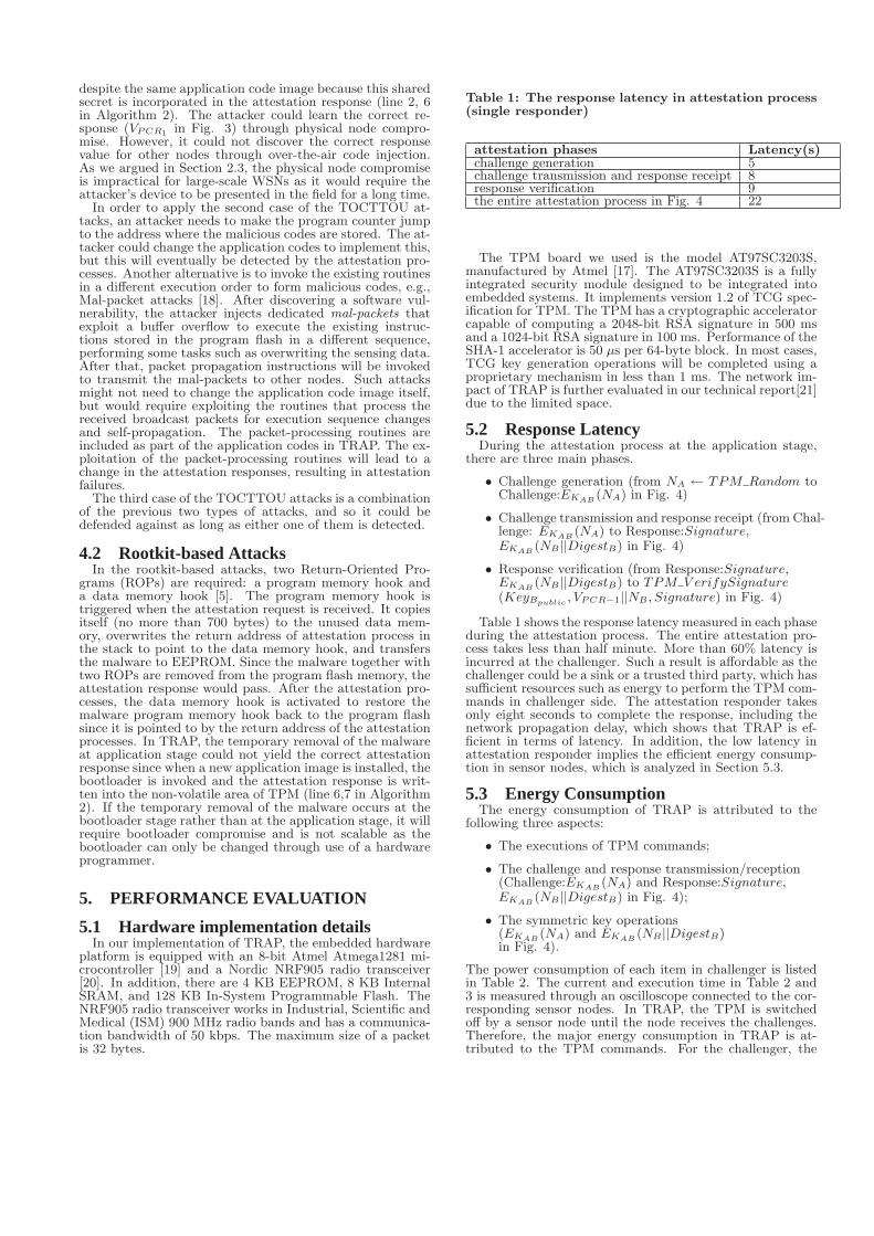
The sequence of the critical events during the applicationstage are shown in Fig. 4. Node A will first generate a 20-byte random nonce, NA with TPM GetRandom. Then itwill try to unseal the shared secret between node A and node
Attestor B Challenger A
PCR1 and
PCR2 are
updated at
bootloader
stage
Decrypt EKAB(NA)
Challenge: EKAB(NA)
Verify DigestB with
NA and NB
TPM_VerifySignature(KeyBpublic ,
VPCR1||NB, Signature)
Request:
KeyBpublic , VPCR1
Response:
EKAB(KeyBpublic||VPCR1)Response:
Signature, EKAB(NB || DigestB )
Trusted third
party
/sink
KAB TPM_Unseal()
Remove KAB
Remove KAB
NA
TPM_GetRandom()
{VPCR1,NB, DigestB}
TPM_NVReadValue(NV_Area1,NA)
Signature
TPM_Sign(VPCR1||NB)
KAB
TPM_Unseal(KAB,PCR2)
Figure 4: The remote attestation process at appli-cation stage: node A is a challenger to verify theattestation response from node B (both node A andnode B are embedded sensors. If node A is a sinkitself, the trusted third party in this figure is notneeded).
B (KAB). If the unseal operation is unsuccessful, the attes-tation process fails and stops (see Fig. 3(a)). Otherwise,NA will be further encrypted with KAB (i.e., EKAB
(NA) inFig. 4, symmetric encryption), which is the challenge. Thennode A will send out the challenge and transit to “wait forresponse” state (see Fig. 3(a)). During this period, node Arequests the expected response and the public key of nodeB (i.e., VPCR1
and KeyBpublicin Fig. 3(a) and Fig. 4) from
a third-party trusted entity (e.g., a base station or a sink).Upon receiving this request, the third-party entity will senda response with requested content, encrypted by the sharedsecret between the attestation responder (node B) and thechallenger(node A) (i.e., EKAB
(KeyBpublic||VPCR1
) in Fig.4).
Upon receiving the challenge from node A, node B wouldunseal KAB . Similarly, if the unseal operation fails, it in-dicates that the PCR2 is different from the version whenKAB is sealed. The attestation process stops and node Bsends back the“attestation fails”message to node A (see Fig.3(b)). Otherwise, node B decrypts the challenge to retrieveNA. NA becomes the input nonce to the TPM NV ReadV alue,which yields NB (output nonce), DigestB (authorization di-gest) and VPCR1
, containing the information on the contentof program memory (see line 2, 6 in Algorithm 2). Afterthat, node B will construct the challenge response by sign-ing the concatenation of VPCR1
and NA (i.e., Signature←TPM Sign(VPCR1
||NA) in Fig. 4) and encrypting the con-catenation of NB and DigestB (i.e., EKAB
(NB ||DigestB)in Fig. 4, symmetric encryption). The signature and theencryption results are sent back to node A for verification.Then node B would remove KAB(Fig. 4) and return to theidle state (see Fig. 3(b)).
On receiving the response from node B, node A would

Shared
secret
retrieval
Send out challenge
(EKAB(NA)) to node BAttestation
Start
TPM_GetRandom()
Tp generate NA
Wait for
response
Response
verification
Attestation
failure
request KeyBpublic ,
VPCR1TPM_Unseal for KAB fails
Attestation response
Received from node B
Attestation
success
Challenge
construction
TPM_Unseal
for KAB succeeds
Verification of DigestBor Signature fails
Verification of DigestBand signature succeeds
�Attestation fails� message received
from node B
Verification of DigestBor Signature fails
(a) A challenger.
Shared
secret
retrieval
Challenge(EKAB(NA))
received
TPM_Unseal
for KAB succeeds
Attestation
failure
TPM_Unseal
for KAB fails
Idle
Send �attestation fails�
Message to node A
Send response (Signature, EKAB(NB||DigestB))
to node A
Response
construction
(b) An attestation responder.
Figure 3: The state diagrams of node A (challenger) and node B (attestation responder).
Algorithm 2 Remote attestation protocol on node B atbootloader stage
Require: The bootloader itself could not be overwritten byover-the-air programming. The shared secret betweenbase station and node B (KBS) is available.
Ensure: the hashed values of application content (Mp),the ending program address of the application content(Addressp) and bootloader content (Mb) are put intothe Platform Configuration Registers.
1: B → TPMB : TPM Startup2: B ← TPMB : hp ← TPM HASH(Mp||KBS)3: B ← TPMB : hb ← TPM HASH(Mb)4: B ← TPMB : VPCR2
←TPM PCRExtend(hb, PCR2)
5: B → TPMB :TPM NV WriteV alue(VPCR2
, NV Area2)6: B ← TPMB : VPCR1
←TPM PCRExtend(hp, PCR1)
7: B → TPMB :TPM NV WriteV alue(VPCR1
, NV Area1)8: B → TPMB : TPM turnoff
first decrypt EKAB(NB ||DigestB) and verify the authoriza-
tion digest (DigestB) with NA and NB . Only if the verifica-tion on DigestB succeeds will node A verify Signature withVPCR1
and KeyBpublic, retrieved from the trusted third-
party or the sink. If the signature verification also passes,the attestation process succeeds. Otherwise, the attestationprocess fails and node B might have been compromised.
4. SECURITY ANALYSIS
4.1 TOCTTOU AttacksThe most common attack against the remote attestation
is referred to as a Time-Of-Check-To-Time-Of-Use (TOCT-TOU) attack. In this type of attack, an attacker memorizesthe correct code image after node compromise. Upon be-ing attested, the attacker could just send back the responsefrom the correct code image to the challenger (time-of-checkcase). However, the actual program flash to be executed isdifferent when invoked (time-of-use case). Three cases mustbe considered in the TOCTTOU attacks:
• The correct code image is copied to another locationin program flash memory and the malicious code isstored in its place. Upon being attested, an attacker
could generate a valid response from the correct codeimage and send it back (time-of-check case). The ma-licious code image replaces the correct code image tobe executed (time-of-use case).
• The correct code image is located in its correct loca-tion in program flash memory so that the attestationwill succeed (time-of-check case). However, the mali-cious code is executed from another location of pro-gram flash memory (time-of-use case).
• Neither the correct image nor malicious image is inthe right location of program flash memory. The ma-licious image is executed whereas the correct image isattested. Obviously, this case is a combination of theabove two cases.
In TRAP, the code image to be attested is hashed andstored in the non-volatile area of the TPM at the bootloaderstage (line 2 in Algorithm 2). This hashed value is readfrom non-volatile area of TPM at the application stage forattestation ({VPCR1
, NB , DigestB} ←TPM NV ReadV alue(NV Area1, NA) in Fig. 3). In orderto use the first case of TOCTTOU attacks, the attackercould take either one of the following two actions:
The attacker returns the correct attestation response (VPCR1
in Fig. 3) rather than retrieve the one from the non-volatilearea of the TPM at the application stage. However, theattacker could not simply return the correct attestation re-sponse (i.e., VPCR1
in Fig. 4) since the response nonce (NB)and the proper authorization digest (DigestB) are also re-quired (see Fig. 4). The output nonce returned to the chal-lenger would be different in each attestation process due tothe randomness of the input nonce (NA in Fig. 4). The sig-nature is over the response nonce ({VPCR1
, NB , DigestB} ←TPM NV ReadV alue(NV Area1, NA) in Fig. 3) so it willbe different despite the same application code image. Theattacker could compromise node B but would not get accessto the KeyBprivate to cover the response nonce given thatKeyBprivate is stored in the TPM.
The attacker injects malicious application code over-the-air. The malicious application code could attempt to writethe correct response value (VPCR1
in Fig. 3) into the non-volatile area at the application stage before the wrong at-testation response value is read from the non-volatile area({VPCR1
, NB , DigestB} ← TPM NV ReadV alue(NV Area1, NA)in Fig. 3). However, the shared secret between the node andbase station (KBS for node B) varies from node to node.The correct attestation response for each node is different
despite the same application code image because this sharedsecret is incorporated in the attestation response (line 2, 6in Algorithm 2). The attacker could learn the correct re-sponse (VPCR1
in Fig. 3) through physical node compro-mise. However, it could not discover the correct responsevalue for other nodes through over-the-air code injection.As we argued in Section 2.3, the physical node compromiseis impractical for large-scale WSNs as it would require theattacker’s device to be presented in the field for a long time.
In order to apply the second case of the TOCTTOU at-tacks, an attacker needs to make the program counter jumpto the address where the malicious codes are stored. The at-tacker could change the application codes to implement this,but this will eventually be detected by the attestation pro-cesses. Another alternative is to invoke the existing routinesin a different execution order to form malicious codes, e.g.,Mal-packet attacks [18]. After discovering a software vul-nerability, the attacker injects dedicated mal-packets thatexploit a buffer overflow to execute the existing instruc-tions stored in the program flash in a different sequence,performing some tasks such as overwriting the sensing data.After that, packet propagation instructions will be invokedto transmit the mal-packets to other nodes. Such attacksmight not need to change the application code image itself,but would require exploiting the routines that process thereceived broadcast packets for execution sequence changesand self-propagation. The packet-processing routines areincluded as part of the application codes in TRAP. The ex-ploitation of the packet-processing routines will lead to achange in the attestation responses, resulting in attestationfailures.
The third case of the TOCTTOU attacks is a combinationof the previous two types of attacks, and so it could bedefended against as long as either one of them is detected.
4.2 Rootkit-based AttacksIn the rootkit-based attacks, two Return-Oriented Pro-
grams (ROPs) are required: a program memory hook anda data memory hook [5]. The program memory hook istriggered when the attestation request is received. It copiesitself (no more than 700 bytes) to the unused data mem-ory, overwrites the return address of attestation process inthe stack to point to the data memory hook, and transfersthe malware to EEPROM. Since the malware together withtwo ROPs are removed from the program flash memory, theattestation response would pass. After the attestation pro-cesses, the data memory hook is activated to restore themalware program memory hook back to the program flashsince it is pointed to by the return address of the attestationprocesses. In TRAP, the temporary removal of the malwareat application stage could not yield the correct attestationresponse since when a new application image is installed, thebootloader is invoked and the attestation response is writ-ten into the non-volatile area of TPM (line 6,7 in Algorithm2). If the temporary removal of the malware occurs at thebootloader stage rather than at the application stage, it willrequire bootloader compromise and is not scalable as thebootloader can only be changed through use of a hardwareprogrammer.
5. PERFORMANCE EVALUATION
5.1 Hardware implementation detailsIn our implementation of TRAP, the embedded hardware
platform is equipped with an 8-bit Atmel Atmega1281 mi-crocontroller [19] and a Nordic NRF905 radio transceiver[20]. In addition, there are 4 KB EEPROM, 8 KB InternalSRAM, and 128 KB In-System Programmable Flash. TheNRF905 radio transceiver works in Industrial, Scientific andMedical (ISM) 900 MHz radio bands and has a communica-tion bandwidth of 50 kbps. The maximum size of a packetis 32 bytes.
Table 1: The response latency in attestation process(single responder)
attestation phases Latency(s)challenge generation 5challenge transmission and response receipt 8response verification 9the entire attestation process in Fig. 4 22
The TPM board we used is the model AT97SC3203S,manufactured by Atmel [17]. The AT97SC3203S is a fullyintegrated security module designed to be integrated intoembedded systems. It implements version 1.2 of TCG spec-ification for TPM. The TPM has a cryptographic acceleratorcapable of computing a 2048-bit RSA signature in 500 msand a 1024-bit RSA signature in 100 ms. Performance of theSHA-1 accelerator is 50 µs per 64-byte block. In most cases,TCG key generation operations will be completed using aproprietary mechanism in less than 1 ms. The network im-pact of TRAP is further evaluated in our technical report[21]due to the limited space.
5.2 Response LatencyDuring the attestation process at the application stage,
there are three main phases.
• Challenge generation (from NA ← TPM Random toChallenge:EKAB
(NA) in Fig. 4)
• Challenge transmission and response receipt (from Chal-lenge: EKAB
(NA) to Response:Signature,EKAB
(NB ||DigestB) in Fig. 4)
• Response verification (from Response:Signature,EKAB
(NB ||DigestB) to TPM V erifySignature(KeyBpublic
, VPCR−1||NB , Signature) in Fig. 4)
Table 1 shows the response latency measured in each phaseduring the attestation process. The entire attestation pro-cess takes less than half minute. More than 60% latency isincurred at the challenger. Such a result is affordable as thechallenger could be a sink or a trusted third party, which hassufficient resources such as energy to perform the TPM com-mands in challenger side. The attestation responder takesonly eight seconds to complete the response, including thenetwork propagation delay, which shows that TRAP is ef-ficient in terms of latency. In addition, the low latency inattestation responder implies the efficient energy consump-tion in sensor nodes, which is analyzed in Section 5.3.
5.3 Energy ConsumptionThe energy consumption of TRAP is attributed to the
following three aspects:
• The executions of TPM commands;
• The challenge and response transmission/reception(Challenge:EKAB
(NA) and Response:Signature,EKAB
(NB ||DigestB) in Fig. 4);
• The symmetric key operations(EKAB
(NA) and EKAB(NB ||DigestB)
in Fig. 4).
The power consumption of each item in challenger is listedin Table 2. The current and execution time in Table 2 and3 is measured through an oscilloscope connected to the cor-responding sensor nodes. In TRAP, the TPM is switchedoff by a sensor node until the node receives the challenges.Therefore, the major energy consumption in TRAP is at-tributed to the TPM commands. For the challenger, the

highest energy consumption is due to TPM Unseal(KAB , PCR2),which incurs 70 mJ (highlighted in Table 2). The energyconsumption for other operations is negligible compared tothis TPM command. As to the attestation responder, TPM Signincurs the highest energy consumption (highlighted in Table3). This phenomenon might lead to the power depletion at-tacks as an attacker could simply send excessive challengesto solicit the attestation responses. A distributed client puz-zle might be designed so that more computational efforts forthe attacker to construct a valid challenge are required. Howto defend against this type of attack would be part of ourfuture work.
6. RELATED WORK
6.1 New attacks and the preventative schemesAlthough worm attacks in the Internet [22] have been in-
vestigated extensively, work on such attacks in WSNs, par-ticularly for Harvard-architecture-based nodes, remains atan early stage. Francillon et al. proposed meta-gadgets toinject the malware into data memory, copy it from the ex-ternal flash memory to RAM, then duplicate the malwarefrom RAM to program memory using the dedicated SPMinstruction from the bootloader [4]. Such an attack couldbe catastrophic once the malware self-propagates by callingthe packet transmission function. The authors in [4] pro-vided a detailed discussion of this attack but did not poseany comprehensive solutions. Gu et al. proposed mal-packetattacks to create malicious codes by altering the executionflow of the existing routines in the program memory [18].The attack requires fewer operations as it does not injectnew code into target nodes. It is also more difficult to de-tect as it does not change the actual content of the programmemory. However, such attack has several limitations asit exploits existing routines only and disappears when thecompromised nodes are reset.
6.2 The existing attestation schemesThe work outlined in Section 6.1 concentrates on preven-
tative measures against sensor node worm attacks. Measuresare also required to detect attacks. The most straightfor-ward detection measure is remote attestation, whose aim isto verify the program flash memory of the sensor nodes. Re-covery measures are taken if an unauthorized alteration inthe program codes has been discovered (e.g., exclusion or re-programming of the corresponding tampered sensor nodes).Though TPM has been deployed on x86 platform to de-tect any rootkit program from the BIOS up to the applica-tion layer[23], it was widely believed that sensor nodes can-not afford the additional hardware required to perform theattestation processes given the limited resources on sensorhardware. Therefore, most of the remote attestation pro-cedures proposed for WSNs were software-based. Seshardriet al. presented SWATT (SoftWare-based ATTestation forEmbedded Devices) to verify the content of the programmemory even while the sensor nodes are running [7]. InSWATT, in addition to a random Message AuthenticationCode (MAC) key, the verifier requires a MAC over a randomsegment of the program flash memory. In order to circum-vent attestations, an attacker would need to interpret thechallenge and generate a response from the correspondingsegment of the untampered program flash codes, which slowsthe attestation processes. The verifier sets a timer right af-ter it sends out the challenge. If there is a timeout eventbefore a response is received, the verifier would suspect thatthe sensor node to be attested has been compromised.
SCUBA (Secure Code Update By Attestation in WSNs) isan approach to detect and repair compromised sensor nodesthrough remote attestation [8]. SCUBA is based on a prim-itive operation called ICE (Indisputable Code Execution) todynamically establish a trusted code base on a remote, un-trusted sensor node. The verification code in SCUBA is a
self-checksum code. The self-checksum code is a sequence ofinstructions that compute a checksum over themselves in away that the checksum would be either wrong or slower toexecute if the sequence of instructions is altered. SCUBArelies on two criteria to determine whether a sensor nodebeing verified is compromised. The first one is the correct-ness of the self-checksum responses, and the other one is theresponse delays. If either of them does not meet the ex-pectation, a verifier will presume the sensor node has beencompromised. Such a node would be either repaired througha code update or revoked as a compromised node.
Obviously, all the above software-based remote attestationprotocols depend on the response time to determine whetheran attacker has interfered with the attestation processes.However, while performing a remote attestation over a net-work, the network communication or the execution statesof nodes will always introduce some unpredicted delays, re-sulting in an inaccurate measurement of the response timeof the attestation processes, and consequent false positives.
Castelluccia et al. presented two new type of attacks tocircumvent malware detection of the above software-basedattestation protocols: rootkit-based attacks against response-time-based attestations [5]. In the rootkit-based attacks, anattacker could copy the malware into EEPROM before anattestation starts and restore it in the program flash afterthe attestation. Despite the incurred response delays due tothe malware transfer, the authors argued that their rootkit-based attacks incur additional 7.4% response delays only,which are faster than the expected value by SWATT (13%)and their attacks could therefore circumvent SWATT’s de-tection [7]. The rootkit attacks further strengthen the con-clusion that the software-based attestation protocols are notsufficiently secure to defend against memory-related attacks.
Christoph et al. proposed a partial hardware-based at-testation protocol to detect a compromised node in cluster-based network [12]. In their paper, the sensor nodes aregrouped into clusters and each cluster has a cluster head,which is a much more powerful device than sensor nodes andis equipped with a cryptographic hardware, i.e. a TrustedPlatform Module (TPM). The sensor nodes within the samecluster can challenge their corresponding cluster head. Theattestation responses are secured by TPMs. In their scheme,only the cluster heads can be verified by attestations. In ad-dition, this paper did not provide any empirical and systemperformance evaluation on their scheme but an analyticalmodel with respect to the energy consumption.
7. CONCLUSIONIn this work, we presented a TPM-enable Remote Attes-
tation Protocol (TRAP) for Harvard-architecture-based em-bedded devices. Instead of employing the TPM on the clus-ter heads only or adopting the software-based attestationdesign, a TPM is equipped with each sensor node. Eachsensor node could be challenged in regard to its programflash content. To the best of our knowledge, TRAP is thefirst protocol for Harvard-architecture-based embedded de-vices where each sensor node is equipped with the additionalhardware. We discussed the potential attacks against TRAPthat can practically beat the software-based attestation pro-tocols, against which we further investigated the countermeasures. The corresponding performance evaluations showthat TPM can improve the efficiency of attestation with af-fordable computational and energy overhead.In the future,We will further investigate the scalability of TRAP, multi-hop attestation and the corresponding attack patterns.
8. REFERENCES[1] A. D. Wood, J. A. Stankovic, and S. H. Son. Jam: a
jammed-area mapping service for sensor networks. InProceedings of 24th IEEE Real-Time SystemsSymposium, pages 286–297, 2003.
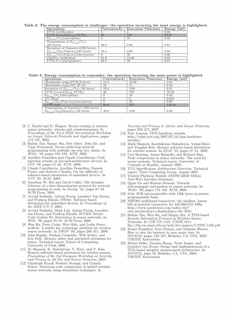
Table 2: The energy consumption in challenger: the operation incurring the most energy is highlighted.Operations Current(mA) Execution Time(ms) Energy (mJ)TPM GetRandom 2 1 0.33TPM Unseal(KAB , PCR2) 46 510 70.33EKAB
(NA)(encryption) 8 18 0.43Transmission of EKAB
(NA)(20 bytes) 36.8 3.68 0.81Reception of Signature(256 bytes),EKAB
(NB ||DigestB)(40 bytes) 18.4 3.68 3.04EKAB
(NB ||DigestB)(decryption) 8 36 0.86DigestB verification 51.2 13.28 2.04TPM V erifySignature 50.4 59 8.91
Table 3: Energy consumption in responder: the operation incurring the most power is highlighted.operations Current(mA) Execution Time(ms) Energy (mJ)(Bootloader stage)PCR Extend 51.2 13.28 2.04(Bootloader stage)NV Write 10 11 0.33Reception of EKAB
(NA) (20 bytes) 18.4 3.68 0.41TPM Unseal(KAB , PCR2) 46 510 70.32EKAB
(NA)(decryption) 8 18 0.43NV Read 2 2 0.012EKAB
(NB ||DigestB)(encryption) 8 36 0.86TPM Sign 60.8 787 143.44Transmission of Signature (256 bytes)EKAB
(NB ||DigestB) (40 bytes) 36.8 3.68 6.09
[2] C. Karlof and D. Wagner. Secure routing in wirelesssensor networks: attacks and countermeasures. InProceedings of the First IEEE International Workshopon Sensor Network Protocols and Applications, pages113–127, 2003.
[3] Hailun Tan, Sanjay Jha, Diet Ostry, John Zic, andVijay Sivaraman. Secure multi-hop networkprogramming with multiple one-way key chains. InWiSec ’08, pages 183–193. ACM, 2008.
[4] Aurelien Francillon and Claude Castelluccia. Codeinjection attacks on harvard-architecture devices. InCCS ’08, pages 15–26. ACM, 2008.
[5] Claude Castelluccia, Aurelien Francillon, DanielePerito, and Soriente Claudio. On the difficulty ofsoftware-based attestation of embedded devices. InCCS ’09. ACM, 2009.
[6] Jonathan W. Hui and David Culler. The dynamicbehavior of a data dissemination protocol for networkprogramming at scale. In SenSys ’04, pages 81–94.ACM Press, 2004.
[7] Arvind Seshadri, Adrian Perrig, Leendert Van Doorn,and Pradeep Khosla. SWAtt: Software-basedattestation for embedded devices. In Proceedings ofthe IEEE S & P, 2004.
[8] Arvind Seshadri, Mark Luk, Adrian Perrig, Leendertvan Doorn, and Pradeep Khosla. SCUBA: SecureCode Update By Attestation in sensor networks. InWiSe ’06, pages 85–94. ACM Press, 2006.
[9] Wen Hu, Peter Corke, Wen Shih, and Leslie Overs.secfleck: A public key technology platform for wirelesssensor networks. In EWSN ’09, pages 296–311. 2009.
[10] John Regehr, Nathan Cooprider, Will Archer, andEric Eide. Memory safety and untrusted extensions fortinyos. Technical report, School of Computing,University of Utah, 2006.
[11] M. Shaneck, K. Mahadevan, V. Kher, and Y. Kim.Remote software-based attestation for wireless sensors.Proceedings of the 2nd European Workshop on Securityand Privacy in Ad Hoc and Sensor Networks, 2005.
[12] Christoph Krauß, Frederic Stumpf, and ClaudiaEckert. Detecting node compromise in hybrid wirelesssensor networks using attestation techniques. In
Security and Privacy in Ad-hoc and Sensor Networks,pages 203–217, 2007.
[13] Nate Lawson. TPM hardware attacks.http://rdist.root.org/2007/07/16/tpm-hardware-attacks/.
[14] Mark Shaneck, Karthikeyan Mahadevan, Vishal Kher,and Yongdae Kim. Remote software-based attestationfor wireless sensors. In ESAS ’05, pages 27–41. 2005.
[15] Carl Hartung, James Balasalle, and Richard Han.Node compromise in sensor networks: The need forsecure systems. Technical report, University ofColorado at Boulder, January 2005.
[16] TCG Specification Architecture Overview. Technicalreport, Trust Computing Group, August 2007.
[17] Trusted Platform Module AT97SC3203S SMbusTwo-Wire Interface Summary.
[18] Qijun Gu and Rizwan Noorani. Towardsself-propagate mal-packets in sensor networks. InWiSec ’08, pages 172–182. ACM, 2008.
[19] 8-bit AVR microcontroller with 128k bytes in-systemprogrammable flash.
[20] NRF905 multiband transceiver- the smallest, lowestbill of material transceiver for 433/868/915 MHz.http://www.nordicsemi.com/index.cfm?obj=product&act=display&pro=83, 2010.
[21] Hailun Tan, Wen Hu, and Sanjay Jha. A TPM-basedRemote Attestation Protocol in Wireless SensorNetworks. In CSE-TR-1105, UNSW,2011.ftp://ftp.cse.unsw.edu.au/pub/doc/papers/UNSW/1105.pdf.
[22] Stuart Staniford, Vern Paxson, and Nicholas Weaver.How to own the internet in your spare time. InSSYM’02, pages 149–167, Berkeley, CA, USA, 2002.USENIX Association.
[23] Reiner Sailer, Xiaolan Zhang, Trent Jaeger, andLeendert van Doorn. Design and implementation of aTCG-based integrity measurement architecture. InSSYM’04, page 16, Berkeley, CA, USA, 2004.USENIX Association.