a three-dimensional parallel time-accurate …
TRANSCRIPT

.P / : ,
PAPER FOR THE SECOND INTERNATIONAL CONFERENCE ON COMPUTATIONAL FLUID DYNAMICS, SYDNEY, JULY 15 - 19, 2002
A THREE-DIMENSIONAL PARALLEL TIME-ACCURATE TURBOPUMP
SIMULATION PROCEDURE USING OVERSET GRID SYSTEMS
Cetin Kiris, [email protected]
William Chan, wchan @ nas.nasa.qov
Dochan Kwak, [email protected]
NAS Applications Branch, M.S, T27B-1NASA-Ames Research Center, Moffett Field, CA 94035
The objective of the current effort is to provide a computational framework for design and
analysis of the entire fuel supply system of a liquid rocket engine, including high-fidelity
unsteady turbopump flow analysis. This capability is needed to support the design of pump
sub-systems for advanced space transportation vehicles that are likely to involve liquid
propulsion systems. To date, computational tools for design/analysis of turbopump flows arebased on relatively lower fidelity methods. An unsteady, three-dimensional viscous flow
analysis tool involving stationary and rotational components for the entire turbopump
assembly has not been available for real-world engineering applications. The present effort
provides developers with information such as transient flow phenomena at start up, and non-uniform inflows, and will eventually impact on system vibration and structures. In the proposed
paper, the progress toward the capability of complete simulation of the turbo-pump for a liquid
rocket engine is reported. The Space Shuttle Main Engine (SSME) turbo-pump is used as a testcase for evaluation of the hybrid MPI/Open-MP and MLP versions of the INS3D code. CAD to
solution auto-scripting capability is being developed for tubopump applications. The relative
motion of the grid systems for the rotor-stator interaction was obtained using overset grid
techniques. Unsteady computations for the SSME turbo-pump, which contains 114 zones with
34.5 million grid points, are carried out on Origin 3000 systems at NASA Ames ResearchCenter. Results from these time-accurate simulations with moving boundary capability are
presented along with the performance of parallel versions of the code.
INTRODUCTIONUntil recently, the high performance pump design process was not significantly different from that of 30 years ago. During the
past 30 years a vast amount of experimental and operational experience has demonstrated that there are many importantfeatures of pump flows, which are not accounted for in the semi-empirical design process. Pumps being designed today are no
more technologically advanced than those designed for the Space Shuttle Main Engine (SSME). During that same time span
huge strides have been made in computers, numerical algorithms, and physical modeling.
Rocket pumps involve full and partial blades, tip leakage, and exit boundary to diffuser. In addition to the geometric
complexities, a variety of flow phenomena are encountered in turbopump flows. These include turbulent boundary layer
separation, wakes, transition, tip w_rtex resolution, three-dimensional effects, and Reynolds numbers effects. In order toincrease the role of Computational Fluid Dynamics (CFD) in the design process, the CFD analysis tools must be evaluated andvalidated so that designers gain confidence in their use. As a part of extending the CFD technology to pump design work,INS3D code has been validated for pump component analysis using data from a rocket pump inducer, and pump impellers _'2.
When rotating and stationary parts are included as shown in Figure 1. unsteady interactions between stationary and rotating
components need to be included. To resolve the complex geometry in relative motion, an overset grid approach is employed inthe current effort. In this approach, a geometrically complex body is decomposed into a number of simple grid components. In
order to solve the entire configuratien including inlet guide vanes, impeller blades, and diffuser blades, an overset grid system

wasconstructedusing34.3Milliongridpointswith114zones.Sinceneighboringgridsmayoverlaparbitrarily,thesegridscanbecreatedindependentlyfromeachother.Thusit iseasiertogeneratehighqualityandnearlyorthogonalgridsusingthisapproach.Connectivitybetweenneighboringgridsisestablishedbyinterpolationatthegridouterboundaries.Additionofnewcomponentstothesystemandsimulationofarbitraryrelativemotionbetweenmultiplebodiesareachievedbyestablishingnewconnectivitywithoutdisturbingtheexistinggrids.
Figure 1. Geometry of a SSME pump including inlet guide vanes, impeller and diffuser blades.
NUMERICAL METHODThe present computations are performed utilizing the INS3D computer code, which solves the incompressible Navier-
Stokes equations for both steady-state and unsteady flows. The numerical solution of the incompressible Navier-Stokes
equations requires special attention in order to satisfy the divergence-free constraint on the velocity field because theincompressible formulation does not yield the pressure field explicitly from the equation of state or through the continuity
equation. One way to avoid the numerical difficulty originated by the elliptic nature of the problem is to use an artificialcompressibility method, developed by Chorin 3. The artificial compressibility algorithm, which introduces a time-derivative
of the pressure term into the continuity equation; the elliptic-parabolic type partial differential equations are transformedinto the hyperbolic-parabolic type. An incompressible flow solver, INS3D, has been developed 4 based on this algorithm.
Since the convective terms of the resulting equations are hyperbolic, upwind differencing can be applied to these terms. Thecurrent version uses Roe's flux-difference splitting 5. The third and fifth-order upwind differencing used here is an
implementation of a class of high-accuracy flux-differencing schemes for the compressible flow equations. To obtain time-accurate solutions, the equations are iterated to convergence in pseudo-time for each physical time step until the divergence
of the velocity field has been reduced below a specified tolerance value. The total number of sub-iteration required varies
depending on the problem, time step size and the artificial compressibility parameter used, and typically ranges from 10 to30 sub-iterations. The matrix equation is solved iteratively by using a non-factored Gauss-Seidel type line-relaxationscheme 6, which maintains stability and allows a large pseudo-time step to be taken. Details of the numerical method can be
found in [4]. The GMRES scheme has also been utilized for the solution of the resulting matrix equation 7. Computer
memory requirement for the flow solver INS3D with line-relaxation is 35 times the number of grid points in words, and
with GMRES-ILU(0) scheme is 220 times the number of grid points in words. When a fast converging scheme, such as aGMRES-ILU(0) solver, was implemented into the artificial compressibility method, previous computations showed that
reasonable agreement was obtained between computed results and experimental data 8.
TURBOPUMP SCRIPTSFor each component of a turbopump (inlet guide vanes, impeller and diffuser), a script was developed to rapidly perform
the various steps of the simulation process prior to the flow solver call. The starting point is the geometry definition of a
component which consists of the hub and shroud profile curves and the surface panels of each distinct blade. Functions
provided by the script include overset surface and volume grid generation, creation of object X-ray maps for hole-cutting
[9], and creation of overset domain connectivity inputs. After running the domain connectivity program OVERFLOW-

D/DCF[10]withthescript-createdinputfile,theresultinggridsandiblankconnectivityinformationareusedasinputfortheINS3Dflowsolver.Figure7'.illustratestheproceduresautomaticallyhandledby thescripts.Importantattributesofeachcomponentareparameterizedin thescripts.Forexample,parameterizedgeometricattributesincludethenumberofbladesfortheinletguidevanes_ndthediffuser;andthenumberofdistinctbladespersectionandthenumberof sectionsfor theimpeller.Parameterizedgridattributesincludehubandshroudsurfacegridspacings,leadingandtrailingedgespacings,viscouswallspacingforthevolumegrids,stretchingratiosandmarchingdistancesforthehyperbolicsurfaceandvolumegrids.All parametersarecontrolledviaaninputfileandthescriptcanberapidlyre-runto generatedifferentconfigurations.Forexample,theusercaninputdifferentgeometrydefinitionsforthehub,shroudandblades,trydifferentnumberofbladesandgridresolutions.
INLET GUIDE VANES (N repeated blades, no tip clearance)
3
IMPELLER
(M sections, N different blades In each section, tip clearance)
Figure 2. Illustration of turbopump scripts for inlet guide vanes and impeller sections.
A high level scripting language Tcl [ 11] is utilized which provides modularity as well as floating point arithmetic capability
(unlike basic shell languages such as C-shell). Although extra time and expertise are needed to construct the scripts, the
pay-off is well worth the effort. The advantages include the ability to rapidly re-run the entire process in just a few minutesversus one or more days of manual effort. Tedious repetitive error-prone inputs are avoided with the scripts while they also
provide a documentation of the eatire grid generation procedure. Grid refinement and parameter studies can also be easilyand efficiently performed. Table 1 shows a comparison of the process time from geometry definition to domain connectivity
inputs for the various turbopump components. Significant time savings is accomplished for generating a large number of
different parameter studies as is frequently practiced in a design environment.

Inlet Guide Vanes Manual Script (coarse) Script (fine)[No. of points (_llions) 7.1 5.8 1.1
rUser time 1 day 43 sec. 20 sec.
Impeller _Vl-__p t_co_eS--- -_e-)-
'No. o--_po'_ i-_Hi0--nsi i9:2-_._i_ 15.2 .................... 8_.._8........
User time 2 weeks 319 sec. 234 sec.
Diffuser Manual Script (coarse) Script (fine)
No. of points (millions) 8.0 6.4 1.6!
User time 1 day 37 sec. 22 sec.
Table 1. Comparison of process time from geoemtry definition to domain connectivity inputs. User time for
the manual process is the total wall clock time for working through the different parts of the process. Usertime for the scripts is the wall clock time to run the scripts on an R12000 300MHz Silicon Graphics
workstation.
PARALLEL COMPUTATIONSParallel computing strategies vary depending on computer architecture such as memory arrangement relative to processingunits. Two approaches have been implemented in the present study: the f'u'st approach is hybrid MPI/OpenMP and thesecond one is Multi Level Parallelism (MLP) developed at NASA-Ames Research Center. The first approach is obtained by
using massage-passing interface (MPI) for inter-zone parallelism _2, and by using OpenMP directives for intra-zone
parallelism [3. INS3D-MPI _2 is based on the explicit massage-passing interface across MPI groups and is designed forcoarse grain parallelism. The primary strategy is to distribute the zones across a set of processors. During the iteration, all
the processors would exchange boundary condition data between processors whose zones shared interfaces with zones on
other processors. A simple master-worker architecture was selected because it is relatively simple to implement and it is acommon architecture for parallel CFD applications. All I/O was performed by master MPI process and data was distributedto the workers. After the initialization phase is complete, the program begins its main iteration loop. Figure 3 shows the
MPI/OpenMP scalability for SSME impeller computations using 19.2 Million grid points.
eoo 19.2M Poinls
soo -rn- 6 MPI groups¢:: 4ooo -i- 12. MR groups
3O0 --,&.- 20 MR groups
2oo --A-- 30 MPI groups
--- !o 100 .. :-==_• (IoE soI- 40
3O
2o6 10 20 30 40 100 200 300
Number of CPUs
Figure 3. INS3D-MPI/OpenMP performance versus CPU counts on SGI Origin platform.
The second approach in Multi-Level Parallelism (MLP) is obtained by using NAS-MLP l+ routines. The shared memory
MLP technique developed at NASA Ames Research Center has been incorporated into the INS3D code. This approachdiffers from the MPI/OpenMP approach in a fundamental way in that it does not use messaging at all. All datacommunication at the coarsest and finest level is accomplished via direct memory referencing instructions. This approach
also provides a simpler mechanism for converting legacy code, such as INS3D, then MPI. For shared memory MLP, thecoarsest level parallelism is supplied by spawning of independent processes via the standard UNIX fork. The advantage ofthe UNIX fork over MPI procedure is that the user does not have to change the initialization section of the large production

M/..P Process 1common/k)caY ae,J_13
code. Library of routines are used to initiate forks, to establish shared memory arenas, and to provide synchronization
primitives. The shared memory organization for INS3D is shown in figure 4. The boundary data for the overset grid system
is archived in the shared memory arena by each process. Other processes access the data from the arena as needed. Figure
5 shows the MLP scalability for SSME impeller computations using 19.2 Million grid points.
MLP Process 2
Common/local/ea,l_
Zones 1,4NILP Data sl_'_ng via I
Load/Stores I330 nanosecond IContrast wiU_
MPl at10 microsecond
Zones 2,3,5
Common/globaU x,y,z
Figure 4. Shared memory MLP organization for INS3D-MLP.
o=
2OO
eo 100
_- 6O
A
o 50e
40mE 30
2O
i • I ! I I I I I I I I I
19.2M Points
"- 12 MLP groups
--&- 2_0 MLP groups
....................................... _,A -¸.
] I I I I I I I I I I =
10 20 30 40 100 200 300
Number of CPUs
Figure 5. Time (see) per iteration for SSME impeller computations using
INS3D-MLP on SGI Origin platforms.
Using INS3D-MLP parallel implementation, time-accurate computations for SSME-rigl configuration have been carried
out on SGI Origin 2000 and 3000 platforms. Instantaneous snapshots of particle traces and pressure surfaces from these
computations are shown in Figure 6. This procedure provides flow-field details not readily available from experiments. The
initial conditions for these simulations were the flow was at rest and the impeller started to rotate impulsively. Three full
impeller rotations were completed in the simulations using 34.3 Million grid points. Using 128 SGI Origin 3000 CPU's,
one impeller rotation was competed in less then 3.5 days. When 480 processors were used, one impeller rotation was
completed in less than 1.5 days. One impeller rotation could be completed in 42 days in 1999. More than 30 times speed-
up has been obtained over 1999 (:apabilities.

Figure 6. Snapshots of particle traces and pressure surfaces from unsteady turbopump computations.
SUMMARYAn incompressible flow solver in steady and time-accurate formulations has been utilized for parallel turbo-pump
computations. Numerical procedures and turbopump scripts for rapid grid system generation and for overset connectivity input
generation are outlined. Performance of the INS3D-MPI/OpenMP and INS3D-MLP versions of the flow solver for SSME
impeller model are presented. Using INS3D-MLP parallel implementation, time-accurate computations for SSME-rig I model,which includes 114 zones with 34.5 Million grid points, have been carried out on SGI Origin platforms. More than 30 times
speed-up has been obtained over 1999 capability for these computations.
REFERENCES[ I] Kiris, C., Chang, L., Kwak, D., and Rogers, S. E., "Incompressible Navier-Stokes Computations of Rotating Flows, _AIAA
Paper No. 93-0678, 1993.[2] Kiris, C. and Kwak, D., "Progress in Incompressible Navier-Stokes Computations for the Analysis of Propulsion Flows/'
NASA CP 3282, Vol II, Advanced Earth-to-Orbit Propulsion Technology, 1994.
[3] Chorin, A., J., "A Numerical Method for Solving Incompressible Viscous Flow Problems" Journal of Computational
Physics, Vol. 2, pp. 12-26, 1967.[4] Rogers, S. E., Kwak, D. and Kiris, C., "Numerical Solution of the Incompressible Navier-Stokes Equations for Steady andTime-Dependent Problems," AIAA Journal, Vol. 29, No. 4, pp. 603-610, 1991.
[5] Roe, P.L., "Approximate Riemann Solvers, Parameter Vectors, and Difference Schemes," J. of Comp. Phys., Vol. 43, pp.357-372 1981.
[6] MacCormack, R., W., "Current Status of Numerical Solutions of the Navier-Stokes Equations," AIAA Paper No. 85-0032,1985.
[7] Rogers, S. E., "A Comparison of Implicit Schemes for the Incompressible Navier-Stokes Equations and Artificial
Compressibility," AIAA Journal, Vol. 33, No. 10, Oct. 1995.[8] Kiris C., and Kwak D., "Aspects of Unsteady Incompressible Flow Simulations," Computers and Fluids Journal, Vol 31,
Numbers 4-7, 2002, pp 627-638.[9] Meakin, R. L., "'Object X-rays for Cutting Holes in Composite Overset Structured Grids," AIAA Paper 2001-2537, 15th
AIAA Computational Fluid Dynamics Conference, Anaheim, California,June 2001.
[10] Chan, W. M., Meakin, R. L. and Potsdam, M. A., "'CHSSI Software for Geometrically Complex Unsteady Aerodynamic
Applications," AIAA Paper 2001-0593, Reno, Nevada, January, 2001.
[11] Welch, B., Practical Programming in Tel and Tk, 3rd ed., Prentice Hall, 1999.[12] Faulkner, T., and Mariani, J., "'MPI Parallelization of the Incompressible Navier-Stokes Solver (INS3D).
http://www.nas.nasa.gov/-faulkner/home.html[13] H. Jin, M. Frumkin and J. Yan, "Automatic Generation of OpenMP Directives and Its Application to Computational Fluid
Dynamics Codes," in the Proceeding of the Third International Symposium on High Performance Computing, Tokyo, Japan,
Oct. 16-18, 2000.[ 14] Taft, J. R., Performance of the OVERFLOW-MLP and LAURA-MLP CFD Codes and the NASA Ames 512 CPU Origin
Systems," HPCC/CAS 2000 Workshop, NASA Ames Research Center, 2000.

A Three-Dimensional Parallel Time-Accurate Turbopump
SimLlation Procedure Using Overset Grid Systems
Cetin Kiris, [email protected]._ov
William Chan, wchan@ nas.nas_.gov
Dachan Kwak, [email protected]._asa.gov
Applications BranchNASA Advanced Supercomputing Division
NASA Ames Research Center
ICCFD2 UniversiW of Sydney, Australia
July 15-19, 2002
Outline
• IntroOuction
• Scope of Present Work
• Computational Challenges
• Computational Technology for Rocket Pump
Flow Solver
Flow Simulation Procedure for Rocket Pump
• A Cast; Study
CFU Applications to Consortium Impeller
• Summary and Discussion

_,_c_ Introduction
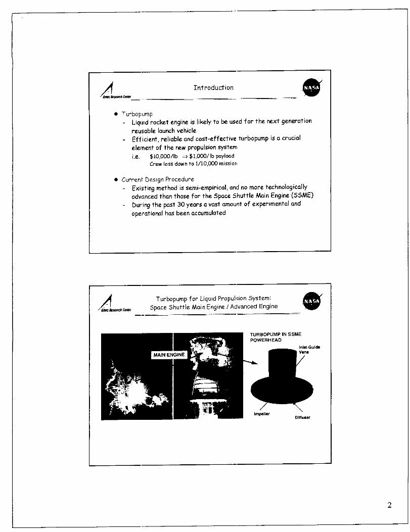
• Turbopump
Liquid rocket engine is likely to be used for the next generationreusable launch vehicle
Efficient, reliable and cost-effective turbopump is a crucial
element of the new propulsion system
i.e. $10,OO0/Ib _ $1,O00/Ib payloadCrew loss down to 1/10,000 missior,
• Curren_ Design Procedure
Existing method is semi-empirical, and no more technologically
advanced than those for the Space Shuttle Main Engine (SSME)
During the past 30 years a vast amount of experimental and
operational has been accumulated
Turbopump for Liquid Propulsion System:
Space Shuttle Main Engine ! Advanced Engine
TURBOPUMP IN SSME
POWERHEAD
Inlet GuideVane
ImpellerDiffuser
2


Scope of Present Work
Computa"ional Approach
There are many important flow features not fully accounted for
in earlier design processes
During the same period, huge strides have been made in
computers, numerical methods/codes, and physical modeling
Flow Simulation Challenges
Geometry is complex, including
full c_ndpartial blades, tip clearance, high-speed impeller
and stationary diffuser
Variety of flow phenomena are encountered such as
boundary layer separation, transition, tip vortex, wake and
cavit,_tion
Scope of Present Work
• Existin!] CFD ToolsThere exist CFD tools for design and analysis primarily based on
rotcltional-steady formulation
• Scope c_f Current WorkCurrent effort is focused on developing an unsteady, 3-D
viscous flow analysis tool
Stationary and rotational components are included for
simulating the entire turbopump assembly
Simulation time from a given geometry to solution is the main
melrics
SSME turbopump is used for test


_/,_._,_ ComputationalChallenges
• ValidaPion
- Experimental data for time-dependant flow are rare
• Computational challenges
- Time-.integration scheme, convergence
- Moving grid system, zonal connectivity
• Computer science
As the computing resources are changed to parallel and distributed
platforms, computer science aspects become important, such as
- Parallel coding and scalability (algorithmic & implementation)
- Portability, transparent coding etc
• Compu-ing resources
- "Grid" computing will provide new computing resources for
problem solving environment
- High-fidelity flow analysis is likely to be performed using "super
node" which is largely based on parallel architecture
_._c_ Flow Solver - INS3D
• Time-integration scheme
Artificial Compressibility Formulation
Introduce a pseudo-time level and artificial compressibility
Ilerate the equations in pseudo-time for each time step until
in:ompressibility condition is satisfied.
Pressure Projection Method
Solve auxiliary velocity field first,
then enforce incompressibility condition by solving a Poisson
ecuation for pressure.


_/_ Validation- Impulsively Started Flat Plate at 90 ° @rob Cem_r
• Time History of Stagnation Point
f__1, ill" "11 _1" |' "l_'Jl" • ";-_"
._)71)
1,." ....... l_ini_e Elern. $o1 (yo-..Kk'la, 19_5)
0 ,o ½ 4
Time
_/_- _,,_c_ Validation-SSME Turbapump Flow Analysis @
• SSME HPFT,) II' ImpellerShrouded impeller: 6 full blades, 6 long partials, 12 short partials 6322 rpm, Re=1.81x10 s per inch
HUB SURFACE C3LORED BY STATIC PRESSURE COMPARISON WITH EXPERIMENTAL DATA
Pressure
l4_
4_
IMPELLEI_ EXIT PLANE AT 51% BLADE HEIGHT
_Experim ent I.... Computal o. I
4
;" R = 5 833 in. r ]
"S
Ci.:umlcm_lial inllc fi_ m_oe iilk (_)
L] : R o 5."]' .......
Olcumfc_SaJ mile from suction Iide (del)


Parallel Implementation of INS3D
• INS3D-MPI
(coarse grain)
T. Faulkner & J. Dactes
• INS3D-MPI_ / Open MPMPI (coarse grain) + OpenMP (fine grain)
Implemented using CAPO/CAPT tools
H, Jin & C. Ki'is
• INS3D-MLPC. Kiris
MPI
Ill
Group 1 Group 2 Group N
commo. _ x_y,z
_ Parallel Implementation of INS3D _'
MPI coarse grain + OpenMP fine grain _ TEST CASE : SSME Impeller
V 60 zones/ 19.2 Million points
t-o
,=_IIEi"
5OOO4OOO
3OOO
2O00
1000
0O0Im04O0
3OO
2OO
100
i J i , i i _ Ill i
\
\
..... [Z]\
[] []
i J ,1 2 3 4 6 10 20 30
Number of CPUs


Parallel Implementation of INS3D
MPI coarse grain + OpenMP fine grain
___ ..... !-- __ , , _ _ , ,,
4oo _ _ _ I -D-- 6 MPI groupsD i I-s- 12MR groups
_o l_. _--A,-- 20 MR groups
nn0 "-_,--_-'-'-'_:i---1 -_- 30 MR gmu_
4= -30
2(I --
1 2 3 4 6 10
OpenMP Threads per MPI Group
TEST CLOSE : SS_?IE Impeller
(_0 zones/ 19.2 Million points
2o_-L([ 10 210 3040 100 200300
Numl:mr ol CPU=
/I Parallel Implementation of INS3D
INS3D-MLP (NAS MLP no pin-tolnode)
/ OpenMP
2OO
t-o
loo
4OeE 3o
2O
I[I T-- ! i , I i _ ii
-"_: : 19.2M Polnls" ........ I - l- 12 MLP groups
............ _++: .... + .... _: .........
' " _ _=: i ....... : "
'_ " .
I _ I i i I i = , I
1 2- $ 4 e 10
OpanMP Threads per MPI Group
TEST CASE : SSME Impeller60 zones/ 19.2 Million points
--_I l , , l , ,l,i
200
100
8OllO
4O
30
2O
7


ParallelImplementationof INS3D
INS3D-MLP (_qAS MLP no pin-to-node)
/ OpenMP
IO0
i __a , "-_ F b i ' '_1 '
_1% -_"_.J --[]-- MPI-OpeNMP Hybrid
! \ _--NASMLP"_ \ I I
--r-- - _ "_3 i I i
; i _ \i i i_\ °
: : i !_ \Ai "
lO 20 30 40 100 200
6O
5O
40
3O
TEST CASE : SSME Impeller
60 zones/ 19.2 Million points
lOO
6O
SO
4O
3O
2O
20 3O 4O
Numl_r o_ CPUs
too
Numbero_CPUI
2oo 300
Space Shuttle Main Engine Turbopump @
Inlet Guide Vane
Impeller
Diffuser


High-fidelity Simulation of 2nd Gen RLV Turbopump
I_let Guide Vanes
23 Zones
6.5 M Points
• Mejot Technical Issues- Pump codes exist, mostly in rotational
frame of refere_nce, for quick design
analysis- Fully 3-D. transient capability is needed
to advance pump technology
To make a timely impact on turbopumpsy_:tems development, wall-clock timefrom CAD to solution has to be short
en<_ughfor design evaluation
_ller
long blades /medium blades /short blades
60 Zones /
19.2 M Grid Points31 Zones8.6 M Poll
CFD Need
kapid grid generation
Accelerated solution time
(parallel implementation)
Large data set management in multiplesites (transmission and storage)
Feature extraction tool
Shuttle Upgrade SSME-rigl
Impeller Grid :60 Zones /19.2 Million Grid Points
Smallest zone 75K/Largest zone : g96K
Less than 156 orphan points.
grid for tip
cle ara n c e
Hub grid
9


Scripting for Acceleration of Grid Generation
Motivation
Significant user's effort neededIn complex process from geometry
to flow solver impeller\
Objective
Develop script system to- generate grids- create domain connectivity Input
- create flow solver Input dlffuserJfor different components
automatically __ Turbopump Scripts _OW SOLVER=_
Approach _'_i_.,=,n _onr._,_ ,.pSI I.=w.oh_.,._tl
Develop one script for each component with ring Interfacebetween components => easy plug In for different designsand combinations of components
Scripting for Acceleration of Grid Generation
INLET GUIDE VANES AND DIFFUSER
Old IGV New IGV Old DIFF New DIFF
No. of points (million) 7.1 1.1 8.0 1.6
Time to build 1/2 day 10 sac. 1/2 day 8 sac.
Script t_mlngs on new grids based on SGI R12k 300MHz processor
Time to build script = 1 day for IGV, 1 day for DIFF
]0


Scripting for Acceleration of Grid Generation
IMPELLER(M secUorm, N different blades In each section, tip clearance)
Manual Script (fine) Script (coarse)No. of pts (million) 19.2 15.2 8.8User tlrrm" ~ 2 weeks 319 sec. 234 sec.(" from geometry ¢1_. to DCF Input with SGI R12k 300Ml-lz CPU)
SSME-rigl / Initial start
Time Step 1_: Impeller rotated 8-degrees at 100% of design speed
I_ -Z-= ,_ _
_RESSURE VELOCITY MAGNITUDE
11


SSME-rigl / Initial start
After 2 1/2 rotation:
Particle Traces and Pressure
• Status
- 34.3 Million Points
- 400 physical time steps in one rotation.
- One physical time-step requires less then
12 minutes walt time with 128 CPU's on
Origin platforms. One complete rotation
requires 3.5-days wall-clock time with
128 processors dedicated to the task.
- I/O and memory m_agement are critical
for wall-clock time reduction
• Issue_': / Needs
- In reality, more than 10% of the
supercamputing facility to one task is not
always practical.
- Need lCiOx bigger supernode or use lower-
fidelity method
- Commun cation to/from designers and
experimental group is a part of critical
te ch _o Ii _gies ( in Grid computing)
Parallel Implementation of INS3D
1NS3D-MLP /40 Groups
RLV 2 "'j Gen Tu,'bo pump
1 14 Zones / 34.3 M grid points
L-. - -.--_-'-\_I -I--l- I--l-- 03000 no-pin400 ........ _----_-.\ ._ !/ l _ _ I -_ 1 _ p1
100 _ i_ _-_-- -----_'_- ......
40 t00 200 300
Number ot CPUm
Per processor Mflop is
between 60-70.
Code optimization for
cache based platforms
is currently underway.
Target Mflops is to
reach 120 per
processor.Increasing number of
OpenMP threads is also
the main objective for
this effort.
12


RLV Turbopump
34.3 Million Grid points RLV Turbopump one impeller rotation
16
LT..
L28CPUs 03K 400Mnz)z
! :: L2_ ceus D3 _4oec_m)
2 .......................................... _ 1.3 day
M LplC.ach¢aFdm'_,480 C[_s O3K(J_MHz]
i .L___ I I L I I ! I I I I I ! i i I E I I i ! L l0cl- _)9 May-2000 Dec-20ClO May-2001 Sop-2001
DATE
_/_ Test Case 1 : Consortium Impeller-DiffuserC_r
-Geometry and operating conditions obtained on January 24. 2002
-Impeller : long blades and short blades, + Diffuser
13


A'_h Test Case 1 : Consortium Impeller-Diffuserc_
-Rotational speed :6322 RPM / Mass Flow Rate : 1;_-10gallons/min.
-Re : 1.37x10⁷ / Lr_f = 4.5225 inches, V_f= Vt_p= 249.5 ft/sec
-39 Million grid points / 41 zones in overset grid systemsdiffuser outflow ring
impeller inflow ring impeller hub
impeller-diffuser
impeller nteroctionblades ings
Test Case 1: Consortium Impeller-Diffuser
diffuser blade collar grids
impeller blades collar grids
14


Test Case 1 : Consortium Impeller-Diffuser
Impeller - diffuser interaction
Test Case 1: Consortium Impeller-Diffuser
INITIAL START / Impeller started roiatin9 at design speed
.......... \ _\ \J
pressure contours and suri aces
_t f'_ES_U_E
@
15


Test Case 1 : Consortium Impeller-Diffuser
First Rotation : Impeller rotated 90 degrees.
pr_.ssure surfaces _otal velocity surfaces
_/_ Test Case 1 : Consortium Impeller-Diffuserxrh_
@First Rotation : Impeller rotated 360 degrees.
pr_sure surfacestotal velocity surfaces
16


Test Case 1 : Consortium Impeller-Diffuser
Second Rotation : t/T = 1.2
pressure surfaces total velocity surfaces
V[L_C ]Ty {'f_(;HIIU DIZ
d_..,._c,_,, Summary
Three-dimensional unsteady flow simulation procedure has been developed
for turbopump in liquid propulsion system
MPZ/OpenMP hybrid parallelism, and MLF l shared memory parallelism has
be(_n implemented in incompressible flow salver, INS3D
Scripting capability from CAD geometry ro solution has been developedanc evaluated for two different configurations
Un:;teady flow computations for RLV 2"d _en baseline turbopump are
performed by using 34.3 Million grid points modelmore than 30 times speed-up has bee_ obtained over 1999 baseline
• Future work
Un ;ready validation and design applications are in progress
l?
