a thesis submitted for the degree of doctor of philosophy ...385912/s4274012_phd...the aerogel-typed...
TRANSCRIPT

Silicon-based anode materials for lithium-ion batteries
Binghui Xu
Bachelor of Engineering
A thesis submitted for the degree of Doctor of Philosophy at
The University of Queensland in 2015
School of Chemical Engineering
I
Abstract
While lithium-ion batteries (LIBs) have found wide applications in customer electronics, such as
cellular phones and lap-top computers, the performance of the currently LIBs does not meet the
market requirements for massive energy storage, such as electric vehicles and smart grids. One of
the critical issues is the low energy capacity of the electrode materials. Graphite has been a common
anode for LIBs, but the maximum capacity (372 mAh·g-1
) of graphite has hindered its application in
advanced LIBs. Substituting graphite with materials of high capacity has become an active research
area. Graphene can store more Li+ than graphite because Li
+ can not only be stored on both sides of
graphene sheets, but also on the edges and covalent sites. Being electric conducting and
mechanically strong, graphene is also an attractive support for other high capacity materials, such as
silicon (Si). Si possesses the highest known theoretical capacity (4200 mAh·g-1
, fully lithiated).
However, Si suffers from a critical problem, namely severe volume change during
charging/discharging, resulting in poor reversibility and rapid capacity decay. This PhD project aims
to improve the stability and suitability of Si nanoparticles (SiNPs) for LIBs.
The first aspect in this thesis is to demonstrate a novel approach to wrapping SiNPs in a reduced
graphene oxide (RGO) aerogel framework. The aerogel-typed RGO architecture not only provided
a porous network to accommodate the volume change of entrapping SiNPs, but also facilitated
electrolyte transport and electron transfer.
The second aspect in this thesis is to report a simple, green and scalable method to prepare RGO
using gallic acid (GA) as a chemical reducing reagent. RGO samples reduced by GA showed a
superior Li+ storage capacity compared with graphite and other reported graphene materials as
anode for LIBs.
The third aspect in this thesis is to report on the preparation of RGO-stabilized SiNPs, a
sandwich-typed composite material (Si@RGO). As a result, good battery performance of Si@RGO
was obtained, 1074 mAh·g-1
at the 5th cycle and 900 mAh·g-1
at the 100th cycle with a capacity
retention of about 84% as well as excellent rate capability.

II
Declaration by author
This thesis is composed of my original work, and contains no material previously published or
written by another person except where due reference has been made in the text. I have clearly
stated the contribution by others to jointly-authored works that I have included in my thesis.
I have clearly stated the contribution of others to my thesis as a whole, including statistical
assistance, survey design, data analysis, significant technical procedures, professional editorial
advice, and any other original research work used or reported in my thesis. The content of my thesis
is the result of work I have carried out since the commencement of my research higher degree
candidature and does not include a substantial part of work that has been submitted to qualify for
the award of any other degree or diploma in any university or other tertiary institution. I have
clearly stated which parts of my thesis, if any, have been submitted to qualify for another award
I acknowledge that an electronic copy of my thesis must be lodged with the University Library and,
subject to the policy and procedures of The University of Queensland, the thesis be made available
for research and study in accordance with the Copyright Act 1968 unless a period of embargo has
been approved by the Dean of the Graduate School.
I acknowledge that copyright of all material contained in my thesis resides with the copyright
holder(s) of that material. Where appropriate I have obtained copyright permission from the
copyright holder to reproduce material in this thesis.

III
Publications during candidature
Journal Papers:
1. Graphene-based electrodes for electrochemical energy storage, Chaohe Xu, † Binghui Xu, † Yi
Gu, † Zhigang Xiong, Jing Sun and X. S. Zhao, Energy and Environmental Science, 2013, 6,
1388-1414. († equally contributed first co-authors).
2. Stabilization of Silicon Nanoparticles in Graphene Aerogel Framework for Lithium Ion Storage,
Binghui Xu, Hao Wu, C. X. (Cynthia) Lin, Bo Wang, Zhi Zhang, X. S. Zhao, RSC Advances,
2015, 5, 30624-30630.
3. Lithium-storage Properties of Reduced Graphene Oxide and its Silicon Based Composites,
Binghui Xu, Jintao Zhang, Yi Gu, Zhi Zhang, Wael Al Abdulla, Nanjundan Ashok Kumar and
X. S. Zhao*, Submitted to Scientific Reports.
4. Mesoporous carbon-coated LiFePO4 nanocrystals co-modified with graphene and Mg2+
doping
as superior cathode materials for lithium ion batteries, Bo Wang, Binghui Xu, Tiefeng Liu,
Peng Liu, Chenfeng Guo, Shuo Wang, Qiuming Wang, Zhigang Xiong, Dianlong Wang and X.
S. Zhao, Nanoscale, 2014, 6, 986-995.
5. Growth of LiFePO4 nanoplatelets with orientated (010) facets on graphene for fast lithium
storage, Bo Wang, Shuo Wang, Peng Liu, Jie Deng, Binghui Xu, Tiefeng Liu, Dianlong Wang,
X. S. Zhao, Materials Letters, 2014, 118, 137-141.
6. The synergy effect on Li storage of LiFePO4 with activated carbon modifications, Bo Wang,
Qiuming Wang, Binghui Xu, Tiefeng Liu, Dianlong Wang and George Zhao, RSC Advances,
2013, 3, 20024-20033.
Conference Proceedings:
1. Self-assembly of Graphene Silicon Nanoparticles into 3D Hierarchical Aerogel Nanocomposite
for Lithium Ion Storage, Binghui Xu, Hao Wu, Zhigang Xiong, C. X. (Cynthia) Lin, Bo Wang,
Peng Liu, and X. S. Zhao. Poster presentation at Asia-Pacific Conference On Electrochemical
Energy Storage & Conversion (APEnergy 2014), 5–8 February 2014, Brisbane Convention &
Exhibition Centre, Australia.

IV
Publications included in this thesis
1. “Chaohe Xu†, Binghui Xu†, Yi Gu†, Zhigang Xiong, Jing Sun and X. S. Zhao*,
Graphene-based Electrodes for Electrochemical Energy Storage, Energy and Environmental
Science, 2013, 6, 1388-1414.”
– incorporated as Chapter 2.
Contributor Statement of contribution
Author Binghui Xu (Candidate) Co-first author
Wrote and edited paper (25%)
Author Dr Chaohe Xu Co-first author
Wrote and edited paper (25%)
Author Yi Gu Co-first author
Wrote and edited paper (25%)
Author Dr Zhigang Xiong Wrote and edited paper (5%)
Author Prof. Jing Sun Wrote and edited paper (5%)
Author Prof. X. S. Zhao Wrote and edited paper (15%)
2. “Binghui Xu, Hao Wu, C. X. (Cynthia) Lin, Bo Wang, Zhi Zhang, X. S. Zhao*, Stabilization of
Silicon Nanoparticles in Graphene Aerogel Framework for Lithium Ion Storage, RSC Advances,
2015, 5, 30624-30630.”
– incorporated as Chapter 4.
Contributor Statement of contribution
Author Binghui Xu (Candidate) Experimental design and performance (80%)
Wrote and edited paper (85%)
Author Dr Hao Wu Experimental design and performance (20%)
Author Dr C. X. (Cynthia) Lin Helped to run freeze drying process
Author Bo Wang Helped to take EDS images
Author Zhi Zhang Helped to take HR-TEM images
Author Prof. X. S. Zhao Wrote and edited paper (15%)

V
3. “Binghui Xu, Jintao Zhang, Yi Gu, Zhi Zhang, Wael Al Abdulla, Nanjundan Ashok Kumar and
X. S. Zhao*, Lithium-storage Properties of Reduced Graphene Oxide and its Silicon Based
Composites, Submitted to Scientific Reports.
– incorporated as Chapter 5 and Chapter 6.
Contributor Statement of contribution
Author Binghui Xu (Candidate) Experimental design and performance (100%)
Wrote and edited paper (80%)
Author Prof. Jintao Zhang Wrote and edited paper (5%)
Author Yi Gu Helped to take FE-SEM images
Author Zhi Zhang Helped to take HR-TEM images
Author Dr Wael Al Abdulla Helped to record Raman spectroscopy
Author Dr Nanjundan Ashok Kumar Wrote and edited paper (5%)
Author Prof. X. S. Zhao Wrote and edited paper (15%)

VI
Contributions by others to the thesis
No contributions by others.
Statement of parts of the thesis submitted to qualify for the award of another degree
None

VII
Acknowledgements
First of all, I would like to thank my parents for their sensible suggestions, directions and unselfish
support in my study career.
Then I would like to express my sincere gratitude to my respectable supervisors, Prof. X. S (George)
Zhao and Prof. Lianzhou Wang for giving me guidance, encouragement and support throughout this
work.
Many thanks go to Prof. Joe Diniz da Costa and Prof. Chengzhong (Michael) Yu for being in my
thesis committee, and for their constructive suggestions throughout my Ph. D candidature career.
I am also grateful for the staffs in School of Chemical Engineering who helped to solve the
financial as well as administrative issues. This project would not have been possible without the
kind assistance from my dear colleagues in Prof. George Zhao’s research group. The facilities and
technical assistance of the Australian Microscopy and Microanalysis Research Facility at the Centre
for Microscopy and Microanalysis at the University of Queensland are acknowledged.
I will take this opportunity to express my appreciation to the China Scholarship Council and the
Australian Research Council for financial support over the PhD study.

VIII
Keywords
Lithium ion batteries, anode, stabilization, silicon nanoparticles, graphene, aerogel, composite
Australian and New Zealand Standard Research Classifications (ANZSRC)
ANZSRC code: 091205, Functional Materials, 60%
ANZSRC code: 090406, Powder and Particle Technology, 20%
ANZSRC code: 090403, Chemical Engineering Design, 20%
Fields of Research (FoR) Classification
FoR code: 0912, Materials Engineering, 50%
FoR code: 0904, Chemical Engineering, 50%

IX
Table of Contents
Abstract ................................................................................................................................................. I
Acknowledgements .......................................................................................................................... VII
Keywords ........................................................................................................................................ VIII
List of figures ................................................................................................................................... XII
List of schemes................................................................................................................................ XVI
List of tables .................................................................................................................................... XVI
List of abbreviations...................................................................................................................... XVII
Chapter 1 Introduction ......................................................................................................................... 1
1.1 Background ................................................................................................................................. 1
1.2 Development history of battery .................................................................................................. 2
1.3 Working principles and terms for LIBs ...................................................................................... 3
1.4 Significance and research objective of the project ..................................................................... 6
1.5 Thesis outline .............................................................................................................................. 7
Chapter 2 Literature review ................................................................................................................. 9
2.1 Cathode ..................................................................................................................................... 10
2.1.1 Layered structured cathode ................................................................................................ 10
2.1.2 Spinel structured cathode ................................................................................................... 12
2.1.3 Olivine structured cathode ................................................................................................. 12
2.1.4 Strategies to enhance the performance of cathode ............................................................. 12
2.2 Anode ........................................................................................................................................ 13
2.2.1 Metallic Li anode ............................................................................................................... 13
2.2.2 Carbonaceous anode .......................................................................................................... 14
2.2.3 Sn and SnO2 based anode................................................................................................... 14
2.2.4 Lithium titanate anode ....................................................................................................... 15
2.2.5 Other metal oxide anode .................................................................................................... 15
2.3 Graphene-based anode .............................................................................................................. 16
2.3.1 Preparation of graphene ..................................................................................................... 16
2.3.2 Graphene-based electrode for LIBs ................................................................................... 24

X
2.4 Silicon-based anode .................................................................................................................. 29
2.4.1 Carbon coated Si electrode ................................................................................................ 30
2.4.2 Metal oxide coated Si electrode ......................................................................................... 32
2.4.3 Polymer modified Si electrode ........................................................................................... 32
2.4.4 Si electrode with designed morphology ............................................................................. 34
2.5 Si/Graphene composite anode .................................................................................................. 38
2.6 Separator ................................................................................................................................... 45
2.7 Electrolyte ................................................................................................................................. 46
2.8 Summary and perspectives ....................................................................................................... 47
Chapter 3 Research methodology ...................................................................................................... 48
3.1 Preparation of GO ..................................................................................................................... 48
3.2 Anode materials preparation ..................................................................................................... 49
3.3 Fabrication of coin cell batteries .............................................................................................. 49
3.4 Electrochemical measurements ................................................................................................ 50
3.5 Materials Characterization ........................................................................................................ 52
Chapter 4 Stabilization of Silicon Nanoparticles in Graphene Aerogel Framework for Lithium Ion
Storage ............................................................................................................................................... 54
4.1. Introduction ............................................................................................................................. 55
4.2 Experimental ............................................................................................................................. 57
4.3 Results and discussion .............................................................................................................. 59
4.4 Conclusions .............................................................................................................................. 70
Chapter 5 Lithium-storage Properties of Reduced Graphene Oxide Using Gallic Acid as Reducing
Agent .................................................................................................................................................. 71
5.1 Introduction .............................................................................................................................. 72
5.2 Experimental ............................................................................................................................. 73
5.3 Results and Discussion ............................................................................................................. 74
5.4 Conclusions .............................................................................................................................. 82
Chapter 6 Silicon Nanoparticles Encapsulated in Reduced Graphene Oxide Framework as a Stable
Anode for Lithium Ion Storage .......................................................................................................... 83

XI
6.1 Introduction .............................................................................................................................. 84
6.2 Experimental ............................................................................................................................. 85
6.3 Results and Discussion ............................................................................................................. 86
6.4 Conclusions .............................................................................................................................. 95
Chapter 7 Conclusions and Recommendations for Future Work ...................................................... 96
7.1 Conclusions .............................................................................................................................. 97
7.2 Recommendations for future work ........................................................................................... 98
References ...................................................................................................................................... 99

XII
List of figures
Figure 2.1 (A) Intramolecular and (B) intermolecular dehydration of GO at hydrothermal conditions.
Procedure (B) gives rise to aggregated products.
Figure 2.2 Illustration of the preparation of graphene based on Fe reduction.
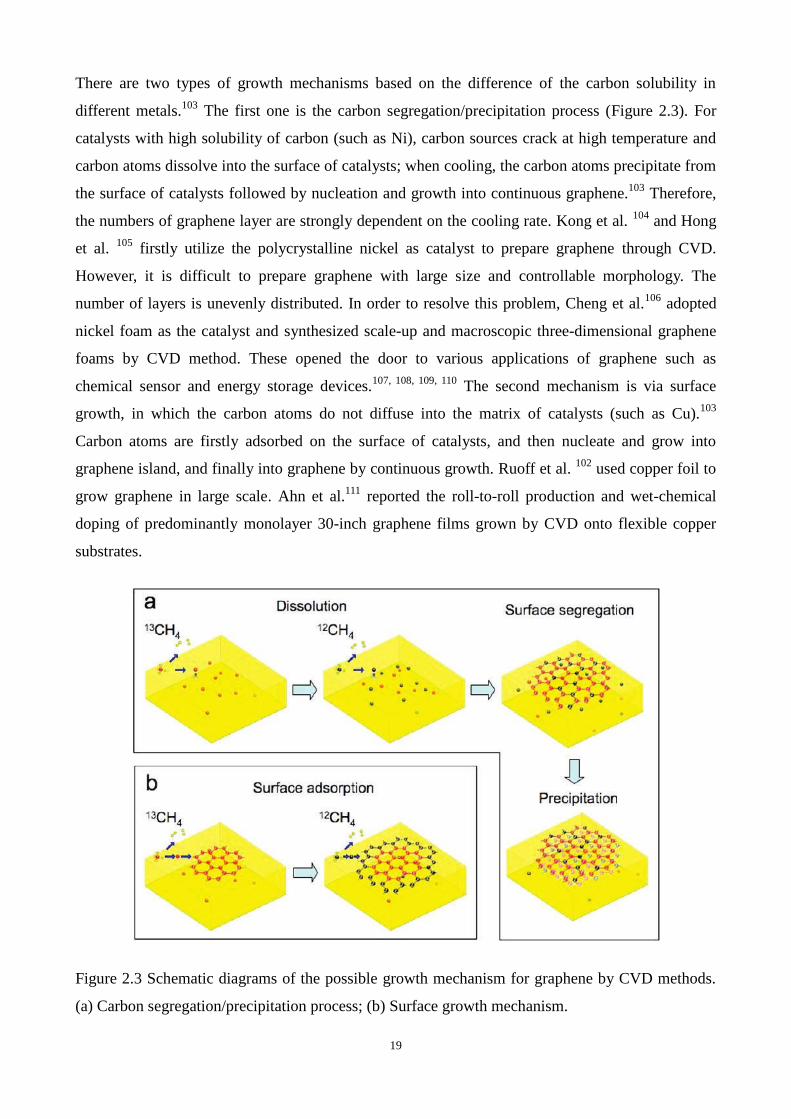
Figure 2.3 Schematic diagrams of the possible growth mechanism for graphene by CVD methods.
(A) Carbon segregation/precipitation process; (B) Surface growth mechanism.
Figure 2.4 Illustration of the bubbling transfer process of graphene from a Pt substrate.
Figure 2.5 Illustration of edge-carboxylation of graphite for graphene in the presence of dry ice. (A)
Pristine graphite; (B) dry ice (solid phase CO2); (C) ECG prepared by ball milling; (D)
schematic representation of physical cracking and edge-carboxylation of graphite by
ball milling in the presence of dry ice.
Figure 2.6 Bottom-up fabrication of atomically precise graphene nanoribbons.
Figuer 2.7 (A) Cyclic voltammograms of the FGNs electrode, (B) Initial discharge/charge profiles
of the FGNs and the RGNs at a current density of 100 mA·g-1
, (C) The cycling
stabilities of the FGNs and RGNs at a high current density of 1000 mA·g-1
, (D) The rate
capabilities and cycle performances of the FGNs and the RGNs at various current
densities, Nyquist plots of the FGNs and RGNs (E) before cycling and (F) after 3
cycles.
Figure 2.8 Schematic illustration of the electrospinning and carbonization steps. (A) The
electrospinning process using a dual nozzle. The PMMA solutions containing SiNPs and
the PAN solution were injected into the core and shell channels of the nozzle,
respectively. (B) After electrospinning, stabilization, and carbonization steps were
employed to complete the core–shell 1D fibers, respectively.
Figure 2.9 (A) Schematic illustration of 3D porous SiNP/conductive polymer hydrogel composite
electrodes. Each SiNP is encapsulated within a conductive polymer surface coating and
is further connected to the highly porous hydrogel framework. SiNPs has been
conformally coated with a polymer layer either through interactions between surface
-OH groups and the phosphonic acids in the crosslinker phytic acid molecules (right
column), or the electrostatic interaction between negatively charged -OH groups and
positively charge PANi due to phytic acid doping. (B-D) Photographs showing the key
steps of the electrode fabrication process. (B) First, SiNPs were dispersed in the

XIII
hydrogel precursor solution containing the crosslinker (phytic acid), the
monomer aniline and the initiator ammonium persulphate. (C) After several minutes of
chemical reaction, the aniline monomer was crosslinked, forming a viscous gel with a
dark green colour. (D) The viscous gel was then bladed onto a 5 × 20 cm2 copper foil
current collector and dried.
Figure 2.10 Synthesis and characterization of an interconnected Si hollow nanosphere electrode. (A)
Schematic of hollow sphere synthesis. Silica particles (R ~175 nm) are first coated onto
a stainless steel substrate, followed by CVD deposition of Si. The SiO2 core is then
removed by HF etching. (B) Typical cross-sectional SEM image of hollow Si
nanospheres showing the underlying substrate and the electrode thickness of ∼12 μm.
(C) SEM side view (45° tilt) of the same sample of hollow Si nanospheres. (D) SEM
image of hollow Si nanospheres scraped using a sharp razor blade, revealing the interior
empty space in the spheres. (E) TEM image of interconnected hollow Si spheres (Rin
~175 nm, Rout ~200 nm). The area outlined by red dotted line indicates a shared shell
between two interconnected spheres. Inset, the selected area electron diffraction pattern
shows the amorphous nature of the sample. (F) Energy dispersive X-ray spectroscopy
(EDS) of a hollow Si sphere. The carbon and copper signals come from the holey
carbon TEM grids.
Figure 2.11 Preparation of bulk 3DNP-Si by dealloying in a metallic melt. (A) Schematic of
producing 3DNP-Si by dealloying in a metallic melt. (B) Schematic of the evolution of
the 3DNP structure by dealloying. (C) SEM image and corresponding EDX mapping of
Si–Mg precursor. Color of the mapping represents atomic concentration defined by the
color bar in the right side of image. (D) SEM image and corresponding EDX maps of
sample after immersion in Bi. (E) SEM image and corresponding EDX map of sample
after etching. (F) Photograph of the bulk 3DNP-Si powder. (G) TEM image and
corresponding selected area diffraction pattern of single grain from the powder.
Figure 2.12 Fabrication of naturally rolled-up C/Si/C multilayer microtubes.
Figure 2.13 Cross-sectional schematic drawing (not to scale) of a high-capacity, stable electrode,
made of a continuous, conducting 3-D network of graphite (red) anchoring regions of
graphene–Si composite. Blue circles: SiNPs, black lines: graphene sheets.
Figure 2.14 Schematic of C-Si-graphene composite formation: (A) natural graphite is transformed
to (B) graphene and then (C) coated by SiNPs and (D) a thin C layer.
Figure 2.15 Schematic of the fabrication (upper panel) and adapting (lower panel) of

XIV
SiNW@G@RGO. The fabrication process mainly includes (A) chemical vapor
deposition (CVD) growth of overlapped graphene sheets on as-synthesized SiNWs to
form SiNW@G nanocables, and (B) vacuum filtration of an aqueous SiNW@G-GO
dispersion followed by thermal reduction. The resulting SiNW@G@RGO can
transform between an expanded state and a contracted state during
lithiation–delithiation cycles, thus enabling the stabilization of the Si material.
Figure 2.16 Fabrication process of the nanocomposite: (A) self-assembly between SiNPs and PDDA
to render the SiNP charged positively (hereafter abbreviated as Si-PDDA nanoparticles);
and, (B) self-assembly between positively charged Si-PDDA nanoparticles and
negatively charged GO followed by freeze-drying, thermal reduction, and HF treatment.
The golden balls and the black coatings represent SiNPs and graphene sheets,
respectively.
Figure 2.17 Schematic of the fabrication process for hybrid nanostructures. (A) A nickel foam
substrate. (B) CVD growth of CNTs on nickel foams. (C) Mixture of Si NPs and GO
suspension in ethanol. (D) Addition of PMMA into the mixed solution. (E) Deposition
of GO/Si/PMMA mixtures onto the CNT-coated nickel foam and (F) thermal annealing
at 700 °C for 4 h.
Figure 3.1 Glove box system MBraun-unilab (1200/780)
Figure 3.2 BTS-5V1mA battery testing equipment
Figure 3.3 CHI660D electrochemical workstation
Figure 4.1 HRTEM image of SiNPs used in this work.
Figure 4.2 XPS survey (A) and Si 2p spectrum of SiNPs (B).
Figure 4.3 SEM (A, B), TEM (C), and HRTEM images (D) of Si/RGO-AG composite.
Figure 4.4 SEM images of SiNPs (A) sample Si/RGO (B), which was prepared by using physical
mixing method and sample Si/RGO-SWAG (C, D), which was prepared by single RGO
wrapping.
Figure 4.5 EDS mapping of Si/RGO-AG.
Figure 4.6 XRD patterns of SiNPs and Si/RGO-AG.
Figure 4.7 Raman spectra of SiNPs and Si/RGO-AG.
Figure 4.8 C 1s XPS spectra of GO (A) and Si/RGO-AG (B).
Figure 4.9 N2 adsorption/desorption isotherms (A) and BJH pore size distribution based on

XV
desorption isotherm of Si/RGO-AG (B). N2 adsorption/desorption isotherm of SiNPs (C); TGA
curves for SiNPs, RGO aerogel and Si/RGO-AG conducted in air (D).
Figure 4.10 (A) Cyclic voltammetry curves for Si/RGO-AG for the first two cycles; (B)
Galvanostatic discharge/charge profiles of the first three cycles; (C) cycling performance of
electrode Si/RGO-AG, Si/RGO-SWAG, and Si/RGO; (D) rate capability of electrode Si/RGO-AG.
Figure 4.11 SEM image of Si/RGO-AG after 40 cycles.
Figure 4.12 Electrochemical impedance spectroscopy (EIS) curves of Si/RGO-AG.
Figure 5.1 (A-B) FESEM images of RGO under different magnifications.
Figure 5.2 (A) Survey XPS patterns of GO and RGO; (B) C1s XPS patterns of RGO and GO.
Figure 5.3 XRD patterns of RGO, GO and graphite.
Figure 5.4 Raman spectra of RGO, GO, and graphite.
Figure 5.5 (A) Cyclic voltammetry curves for RGO; (B) Galvanostatic discharge-charge profiles of
the first three cycles for RGO; (C) cycling performances of RGO and graphite at the current rate of
200 mA·g-1
; (D) rate capability of RGO composite.
Figure 6.1 (A and B) Top-view FESEM images of Si@RGO under different magnifications (The
white arrows and red circles in Figure 6.1B show RGO wrapping layers and encapsulated SiNPs,
respectively.); (C) Cross-sectional view FESEM image of Si@RGO; (D) TEM image of Si@RGO
composite.
Figure 6.2 Survey XPS patterns of sample Si@RGO 1:1 (A) and N2 adsorption/desorption
isotherms of sample Si@RGO 1:1.
Figure 6.3 FESEM images of RGO (A) and Si@RGO composites with different Si/GO ratios (1:2 B,
1:1 C, 2:1 D).
Figure 6.4 (A) XRD patterns of Si@RGO, SiNPs and RGO; (B) Raman spectra of Si@RGO, SiNPs
and RGO.
Figure 6.5 (A) Cyclic voltammetry curves for Si@RGO 1:2 composite; (B) Galvanostatic
discharge-charge profiles of the first three cycles.
Figure 6.6 (A) cycling performances of Si@RGO composites with different Si/GO mass ratios at a
current density 200 mA·g-1
; (B) rate capabilities of Si@RGO composites with different Si/GO mass
ratios.
Figure 6.7 (A) cycling performances of Si@RGO 2:1 composite using different binders; (B) cycling
performances of Si@RGO 1:1 composite using different binders.

XVI
List of schemes
Scheme 1.1 The scheme of a common LIB: (A) aluminium current collector; (B) metal oxide
cathode active material; (C) porous separator in organic electrolyte; (D) solid electrolyte
interface layer; (E) graphite anode active material and (F) copper current collector.
Scheme 3.1 Illustration of coin cell battery fabrication.
Scheme 4.1 Schematic illustration of the preparation of Si/RGO-AG: (A) surface modification of
SiNPs with PDDA; (B) formation of Si@GO composite via electrostatic interactions; (C)
reduction of Si@GO using GA to form Si@RGO hydrogel; (D) dispersing Si@RGO in a
GO suspension for further reduction using GA.
Scheme 6.1 Schematic of the preparation procedure of Si@RGO composite: (A) surface
modification of SiNPs with poly(diallydimethylammonium chloride, PDDA); (B)
adding GO to form a Si@GO composite via electrostatic interactions; (C) reduction of
the Si@GO to obtain a Si@RGO composite; (D) freeze drying and thermal treatment
to obtain the final product.
List of tables
Table 1.1 History of electrochemical cell development
Table 5.1 Comparison of graphene anode materials prepared by reducing GO using various methods

XVII
List of abbreviations
3DNP three-dimensional nanoporous
AG artificial graphite
ALD atomic layer deposition
APTES (3–aminopropyl)triethoxysilane
BET Brunauer-Emmett-Teller
CMC sodium carboxymethyl cellulose
CNT carbon nanotube
CV cyclic voltammetry
CVD chemical vapor deposition
DEC diethyl carbonate
DI deionized
DMC dimethyl carbonate
EC ethylene carbonate
ECG edge-selectively carboxylated graphite
EDA Ethylenediamine
EDS energy dispersive X-ray spectroscopy
EI electrified interface
EIS electrochemical impedance spectroscopy
EMC ethyl methyl carbonate
GA gallic acid
GNS graphene nanosheet
GO graphene oxide
HEV hybrid electric vehicle
HOPG highly oriented pyrolitic graphite
HRTEM High-resolution transmission electron microscopy

XVIII
LIB lithium-ion battery
MPECVD microwave plasma enhanced chemical vapor deposition
NMR nuclear magnetic resonance
PAA poly (acrylic acid)
PAN polyacrylonitrile
PANI polyaniline
PDDA poly(diallydimethylammonium chloride)
PE polyethylene
PHEV plug-in hybrid electric vehicle
PP polypropylene
PPy polypyrrole
PVDF polyvinylidene fluoride
RGO reduced graphene oxide
SA sodium alginate
SEI solid electrolyte interphase
SEM scanning electron microscopy
SHE standard hydrogen electrode
SiNP Si nanoparticle
SiNW Si nanowire
SNWA Si nanowire arrays
SWCNT single-walled carbon nanotubes
TEM transmission electron microscopy
TGA thermogravimetric analysis
XPS X-ray photoelectron spectroscopy
XRD X-ray diffraction

1
Chapter 1 Introduction
1.1 Background
Environmental pollutions, global warming, increasing demand of energy supply as well as the
accompanying surging price of the traditional energy sources have been attracting worldwide
concerns. People all over the globe are trying their utmost to explore an alternative way to substitute
the exhausting fossil energy sources. Renewable energy such as: solar radiation, wind and waves
have already entered people’s horizon. On the other hand, these clean energy sources require energy
storage devices. The common energy carriers are the electricity grid, electromagnetic waves, and
chemical energy. The most convenient one for energy storage is chemical battery.
Battery possesses the advantages such as: the portability of stored chemical energy and deliver this
chemical energy as electrical energy with high conversion efficiency, no gaseous exhaust, etc.1 The
great success of LIBs in portable electronic divisions has been achieved since it was first

2
commercialized by Sony at early 1990s. The higher volumetric and gravimetric energy density of a
LIB has already made it popularly used in small electrical devices, such as cellular phones and
lap-top computers.2 Furthermore, LIBs are also regarded as the most promising green generation of
energy storage technologies applied in hybrid electric vehicles (HEVs), plug-in hybrid electric
vehicles (PHEVs). However, several unfavorable issues including cost, safety, stored energy density,
charge/discharge rates, and lifetime continue to plague the further utilization of the LIBs for the
potential mass market of electric vehicles.3
1.2 Development history of battery
The first electrochemical cell is discovered by an Italian physicist Alessandro Volta (1800) because
he demonstrated that two different metals, zinc and copper, could generate electric current by
decomposing water and generating hydrogen when they were immersed in acidic electrolyte. This
discovery was followed a few decades later by Michael Faraday’s major advances in developing the
laws of electrochemistry, and the subsequent development of rechargeable batteries with aqueous
electrolytes, notably lead–acid (Gaston Planté, 1859), nickel–cadmium (Waldemar Jungner, 1899),
and nickel–iron (Thomas Edison, 1901) systems. Nickel–cadmium and nickel–iron batteries were
the forerunners of modern-day nickel–metal hydride batteries, introduced into the market in 1989.4
Li-based rechargeable batteries were first proposed in the early 1960s and since then the battery has
undergone several transformations. Initially, metallic Li was selected as the anode but it induced
serious safety hazards because of dendritic Li grows and pierces the separator membrane during
cycling and finally triggers short circuit.5 The most inspiring breakthrough in LIB technology
happened in 1991 owing to Sony Corporation’s introduction of a high-voltage (~3.7 V) and
high-energy LixC6/non-aqueous liquid electrolyte/Li1-xCoO2 cell for portable electronic applications.
Furthermore, the discovery of stable, liquid organic carbonate solvents allowed the reversible
operation of these LIBs at high voltage, at least up to 4.2 V. And since 1991, graphite has remained
the anode material of choice.4 Table 1.1
4, 6 lists the landmarks of the history of batteries.

3
Table 1.1 History of electrochemical cell development
Battery
type
Invented
year Battery inventor Battery name
Primary
battery
1800 Alessandro Volta Voltaic pile
1836 John Frederic Daniel Daniel cell
1844 William Robert Grove Grove cell
1860 Callaud Gravity cell
1866 Georges-Lionel Leclanché Leclanché wet cell
1888 Carl Gassner Zinc-carbon dry cell
1955 Lewis Urry Alkaline battery
1970 No information Zinc-air battery
1975 Sanyo Electric Co. Lithium-manganese cell
2004 Panasonic Corporation Oxyride battery
Secondar
y battery
1859 Raymond Gaston Planté Planté lead-acid cell
1881 Camille Alphonse Faure Improved lead-acid cell
1899 Waldmar Jungner Nickel-cadmium cell
1901 Thomas Edison Nickel-iron cell
1946 Union Carbide Company Alkaline manganese
secondary cell
1970 Exxon laboratory Lithium-titanium disulfide
1980 Moli Energy Lithium-molybdenum
disulfide
1990 Samsung Nickel-metal hydride
1991 Sony Lithium-ion
1999 Sony Lithium polymer
1.3 Working principles and terms for LIBs
A typical LIB can be represented below:
n 6 x( )C |1 mol/L LiPF -EC+DEC| LiMO ( ) (1)
Where C stands for a carbonaceous material and M indicates a metal. On the cathode, the following
reaction occurs:
charge- +
x 1-y xdischargeLiMO -ye Li MO +yLi (2)

4
Whereas on the anode, the following reaction takes place:
charge+ -
n y ndischargeC +yLi +ye Li C (3)
The overall reaction becomes:
charge
x n 1-y x y ndischargeLiMO +C Li MO +Li C (4)
Scheme 1.1 illustrates the working mechanism of a typical LIB. During charging process, lithium
ions are deintercalated from the layer-structure cathode, then transported through the porous
separator in the electrolyte and intercalated into the carbonaceous anode. During discharging
process, the lithium ions are deintercalated from the anode and intercalated back to the empty sites
between the layers in the cathode. Therefore, such a LIB is called “rocking chair” battery from the
view point of lithium ion transfer mechanism.
Scheme 1.1 The scheme of a common LIB: (a) aluminium current collector; (b) metal oxide cathode
active material; (c) porous separator in organic electrolyte; (d) solid electrolyte interface layer; (e)
graphite anode active material and (f) copper current collector.
The battery capacity is defined as the amount of charge that can be obtained via the charging and
discharging processes under specific conditions. The theoretical capacity of a battery is determined
by the amount of an active electrode material given by:

5
126.8 (Ah)o
o o
mC n m
M q
(5)
where Co in Ah is the theoretical capacity, mo in g is the mass of the active material participating in
the electrochemical reaction, M in g/mol is the molar weight of the active material, n is the number
of electron involved in the reaction, and q is the electrochemical equivalence.
For example, the theoretical capacity of the commonly used graphite anode LiC6 is calculated as
below:
+
6 6LiC Li +C +e (6)
6
1LiC =26.8 1000 339.50 (mAh/g)
78.94
(7)
The actual capacity of a battery at constant current is given by:
C i t (8)
or
2
1
1 t
tC Vdt
R
(9)
at a constant resistance.
The theoretical energy value of a battery is the maximum value that can be delivered:
o o oW C V (10)
Where Vo is the standard potential.
The maximum power that can be produced by the battery is given by:
o oP iV (11)
The actual energy and power are determined by substituting the working voltage into Equations (10)
and (11), respectively.

6
1.4 Significance and research objective of the project
Graphite, the conventional and commercialized anode material for LIBs suffers from low
theoretical capacity (372 mAh·g-1
), hampering its practical application in advanced LIBs. Si is a
promising anode material for new-generation LIBs because of its high theoretical Li ion storage
capacity (~4200 mAh·g-1), significantly higher than that of graphite. Si also features low discharge
potential (~0.4 V vs Li/Li+), rich natural abundance, and environmental benignity.
7, 8, 9 However, the
realization of Si as a LIB anode has been hindered because Si suffers from low intrinsic electronic
conductivity and large specific volume changes (>400%) during lithiation and delithiation, resulting
in poor rate capability, pulverization of Si particles and electrical disconnection from the current
collector, finally leading to a rapid capacity fading.10, 11, 12
Two approaches are usually taken to
improve its electrode performance. One is to shorten the electronic and ionic transport length by
fabricating nanostructured Si. The other is to increase the electron transport by conductive carbon
coating or adding conductive additives such as carbon nanotubes, graphene.13
Although using
nano-size Si particles or wires can efficiently decrease Li+ diffusion length and accommodate large
stress and strain without cracking, nano-sized Si is easy to form aggregations, thus leading to poor
cycling performance.14
Graphene, a monolayer of SP2 carbon atoms arranged in a 2D honeycomb network, has been shown
to be effective for stabilizing Si nanoparticles (SiNPs) to prepare composite anode materials for
LIB.15, 16, 17, 18, 19, 20, 21, 22, 23
Due to its high electric conductivity, superior mechanical strength and
flexibility, graphene can enhance overall electric conductivity and facilitate Li+ diffusion when
preparing composite material with Si, thus improving the electrochemical performance of the
materials.24, 25, 26, 27, 28
Apart from stabilizing SiNPs, graphene as an anode candidate for LIB can
store more lithium ions than graphite because lithium ions can not only be stored on both sides of
graphene sheets, but also on the edges and covalent sites.15
Chemical reduction of GO is regarded as
an economical and scalable method, which has been widely employed for graphene preparation.
Generally, the RGO product tends to aggregate because of π–π stacking. Besides, some reducing
agents (i.e. sodium borohydride29
, hydroxylamine30
and hydrazine31
) are toxic or explosive.
Therefore, sustained efforts have been paid to explore green and safe approaches to reducing GO.
Moreover, it is important to design a unique mechanically strong and conductive RGO framework
to confine nano-sized Si and form stable solid electrolyte interphase (SEI) layers.
The objective of this project is set to design and prepare Si-based composite electrode with RGO for

7
advanced LIBs taking the followings into consideration:
(1) Explore a facile, green, scalable and cost-efficient way to prepare RGO architecture by
chemically reducing GO;
(2) Prohibit the severe aggregation of SiNPs during material synthesis by surface modification and
GO sheets confining;
(3) Alleviate the heavy volume changes of SiNPs, and improve the overall electric conductivity
and ionic conductivity of the electrode using designed RGO architecture;
(4) Prepare mechanical strong electrode and simplify the electrode preparation process.
1.5 Thesis outline
This thesis contains seven chapters presented in the following sequences:
Chapter 1 Introduction – This chapter first gives a brief introduction of research and development
history of battery as well as LIB working principles, then introduces the significance of the project
and summarizes the research objectives.
Chapter 2 Literature Review – Different components for LIBs are overviewed in this chapter first.
Then Si and RGO based anodes are analyzed. Finally the latest research achievements of
Si/Graphene composite anode are emphasized and summarized.
Chapter 3 Research Methodology – This chapter describes configuration and assembly of LIBs in
lab, the battery performance measurement methods, and the characterization techniques.
Chapter 4 Stabilization of Silicon Nanoparticles in Graphene Aerogel Framework for Lithium
Ion Storage – This chapter demonstrates a novel approach to wrapping SiNPs in three-dimensional
RGO aerogel. The graphene-wrapped SiNPs aerogel showed improved cycling performance with
excellent rate capacity than the samples prepared using simple mixing method.
Chapter 5 Lithium-storage Properties of Reduced Graphene Oxide Using Gallic Acid as
Reducing Agent – This chapter introduces a facile and scalable chemical reducing approach to
preparing highly-reduced porous RGO architecture using gallic acid as reductant. The RGO
particles showed inspiring lithium ion storage capability as anode for LIB.

8
Chapter 6 Silicon Nanoparticles Encapsulated in Reduced Graphene Oxide Framework as a
Stable Anode for Lithium Ion Storage – This chapter describes a new approach to stabilize SiNPs
by encapsulating SiNPs in reduced RGO framework to form a micron-sized sandwich-type
composite with different starting Si/GO mass ratios. Good cycling performance and rate capability
were achieved.
Chapter 7 Conclusions and recommendations for future work – This chapter is a summary of
the thesis with recommendations for the future work.

9
Chapter 2 Literature review
A LIB mainly consists of a cathode, an anode, electrolyte and a separator. The cathode materials are
commonly Li-containing transition metal oxides with a layered structure (such as lithium cobalt
oxide) or tunnel-structured materials (such as lithium manganese oxide). The anode materials
include insertion-type materials (such as graphite, TiO2, etc.), conversion-type materials (such as
iron oxides, nickel oxides, cobalt oxides, etc.), and alloying-type materials (such as Si, Sn, etc.).
The electrolyte is supposed to be a good ionic conductor and electronic insulator. Most of the
electrolytes are based on the solution of inorganic lithium salts dissolved in a mixture of two or
more organic solvents. The function of the separator is to prevent short circuit between the two
electrodes and to provide abundant channels for transportation of Li ion during the process of
charging/discharging.

10
2.1 Cathode
Cathode materials are typically Li-containing oxides of transition metals with layer structure, which
undergo oxidation reaction to higher valences when lithium is removed. While oxidation of the
transition metal can maintain charge neutrality in the compound, large compositional changes often
lead to phase changes, so crystal structures that are stable over wide ranges of composition must be
used. This structural stability is a particular challenge during charging when most (ideally all) of the
lithium is removed from the cathode. During discharge lithium is inserted into the cathode material
and electrons from the anode reduce the transition metal ions in the cathode to a lower valence.32
The key requirements for a successful cathode material in a rechargeable LIB are as follows:33
(1) The material contains a readily reducible/oxidizable ion, for example a transition metal;
(2) The material reacts with lithium in a reversible manner;
(3) The material reacts with lithium with a high free energy of reaction;
(4) The material reacts with lithium very rapidly during both insertion and extraction processes;
(5) The material is supposed to be a good electronic conductor, preferably a metal;
(6) The material should be stable. For example, there won’t be structure changing or degrading
if over-discharging or over-changing takes place;
(7) The material should be less expensive;
(8) The material is better to be environmentally friendly;
During the early age of LIBs, metal chalcogenides (e.g., TiS2 and MoS2) and manganese or
vanadium oxides were chosen as the cathode materials to pair with the metallic Li or the graphite
anode. After several decades’ development and the increasing requirement of high-performance
electrode material from large-scale energy storage, the main focus on the cathode materials for LIBs
has been devoted to layered, structured hexagonal LiCoO2, spinel LiMn2O4, olivine LiFePO4, and
their derivatives.
2.1.1 Layered structured cathode
There are three basic layered cathode materials: LiCoO2, LiNiO2 and LiMnO2.

11
LiCoO2 has been and is still widely used in commercialized LIBs since its first patented as a lithium
intercalation cathode material in 1980 by Goodenough and its first appearance in the commercial
LIBs by SONY in 1991.34
It possesses the advantages of large theoretical capacity (274 mAh·g-1
,
calculated based on extraction of 1 mole of Li+ from LiCoO2) and high working voltage (> 3.4 V).
35
The cathode undergoes serious phase transformation between hexagonal and monoclinic when the
cathode charged above 4.2 V. Since this phase transformation leads deterioration of cycling
performance, practical capacity is restricted as half of theoretical capacity.36
Although the LiCoO2
cathode dominates the LIB market, there is a limited availability of cobalt, which makes the cost of
a single battery expensive. This price limits its application only in the area of small cells of portable
electrical devices, such as those used in computers, cell phones, and cameras.33
Lithium nickel oxide, LiNiO2, due to the configuration of low spin Ni3+
:t2g6eg
1, electrons are
removed only from the eg band that barely touches the top of the O2-
:2p band, thus most of the
lithium can be extracted from LiNiO2 prior to the oxygen loss and a high capacity of around 200
mAh·g-1
is generated.37
LiNiO2 has the same structure with lithium cobalt oxide but has not been
pursued in the pure state as a battery cathode for a variety of reasons, even though nickel is less
expensive than cobalt. First, it is not clear that stoichiometric LiNiO2 exists. Most reports suggest
excess nickel as in Li1-yNi1+yO2; thus, nickel is always found in the lithium layer, which pins the
NiO2 layers together, thereby reducing the lithium diffusion coefficient and the power capability of
the electrode. Second, compounds with low lithium contents appear to be unstable due to the high
effective equilibrium oxygen partial pressure, so that such cells are inherently unstable and
therefore dangerous in contact with organic solvents.33
There are two structures of LiMnO2, the layered structure and the orthorhombic phase. The layered
structure is thermodynamically more stable. The layered LiMnO2 can be synthesized using the soft
chemical method such as ion-exchange from the sodium analogue NaMnO2.38
Generally speaking,
the manganese based material has advantages of low price and low toxicity and high initial charge
capacity. However the main shortcoming of the layered LiMnO2 is the crystallographic
transformation to more stable spinel structure during electrochemical cycling. Mn3+
is a Jahn-Teller
ion and the redox reaction between Mn3+
and Mn4+
will result in local distortion and quick capacity
decay.39

12
2.1.2 Spinel structured cathode
LiMn2O4 is an extensively studied cathode material for LIBs. Compared with LiCoO2, it possesses
the advantages of cheaper price, lower toxicity, and higher rate capability. However, the main
drawback of spinel LiMn2O4 cathode is drastic capacity fading, especially at high temperatures, and
shows a low capacity of around 120 mAh·g-1
.40
The dissolution of manganese from the lattice into
the electrolyte due to a disproportion of Mn3+
ions into Mn2+
and Mn4+
plays a vital role for the
problem, which is facilitated by trace amount of HF generated in the electrolyte.41
2.1.3 Olivine structured cathode
In 1997, Goodenough and co-workers42
firstly reported reversible lithium intercalation in the
phosphate polyanionic compound of LiFePO4. The Olivine-type of LiFePO4 with a theoretical
capacity of 170 mAh·g-1
has been considered as a promising cathode material for LIBs.43,44
The
main drawbacks of LiFePO4 are the poor conductivity resulting from the low Li ion diffusion rate
and low electronic conductivity.45
2.1.4 Strategies to enhance the performance of cathode
One can never neglect the fact that the nano-particle forms of lithium transition metal oxides such
as LiCoO2, LiNiO2, or their solid solutions can react with the electrolyte and lead to safety problems.
In the case of LiMn2O4, the use of nanoparticles causes undesirable dissolution of Mn as mentioned
before. Significant efforts have been made to increase the stability of these nanocrystalline lithium
metal oxides. Better stability can be achieved by coating the electrode materials with a nano-sized
stabilizing surface layer.
To improve the electrochemical kinetics, the cathode materials need to be embedded within an
electronically conducting network, for example, some thin coating of conductive material. The
coatings must be thin enough, on the nanoscale, so that ions can penetrate through them without

13
appreciable polarization. Furthermore, the internal electrical field generated by electrons may
enhance the ionic motions. Such surface modifications alleviate the problem of low electronic
conductivity, at the same time, reducing the size of active material would shorten the diffusion
length of Li+. The realization of such nanostructured composites consisting of cathode materials and
conductive additives makes it possible to utilize theoretical capacities at intermediate or even higher
current rates.43
2.2 Anode
Anode is the negative electrode of a primary cell and is always associated with oxidation reaction,
accompanying with release of electrons to external circuit. In a secondary cell, anode is the negative
pole during discharge but the positive pole during charge. The basic requirements for a LIB anode
material are that the material should have minimal volume expansion and resulting stress during
charge/discharge process, high electronic conductivity, low irreversible capacity during initial
charging or intercalation process, stable under wide operating temperature window in a highly
reducing environment, and low specific surface area (typically < 2 m2/g) for optimal performance
and safety.34
2.2.1 Metallic Li anode
The most elementary anode material for lithium-based batteries is metallic lithium, which has been
used for primary batteries since the early 1960s. By possessing the lowest standard potential (–3.05
V vs. a standard hydrogen electrode (SHE)) and the lowest atomic weight (6.94 g·mol–1
; specific
gravity: ρ= 0.53 g·cm–3
) among all metals, the utilization of metallic lithium as an anode offers the
realization of galvanostatic cells having an extremely high capacity (3820 mAh·g-1
) and energy
density (1470Wh·kg-1
).46
Consequently, metallic lithium was also considered as the candidate of
choice for secondary LIBs. However, lithium metal cells have one severe drawback, namely,
inhomogeneous lithium plating, which hinders their commercial development. This uneven
deposition of lithium onto the anode surface upon charge results in the formation of so-called
dendrites. And the disordered metallic deposit gives rise to a poor Coulombic efficiency, resulting

14
from such a fine Li metal often acts as an active site inducing reductive decomposition of
electrolyte components. Part of the deposit may become electrically isolated and shedding may also
occur. These dendrites consist of high surface area, highly branched lithium metal structures, which
continuously grow, may easily penetrate into the separator and eventually cause internal short,
resulting in heat generation and contingent ignition. Hence the hazardous nature of Li has paved
way to explore some other safer anode materials, possessing comparably the same electrochemical
features as that of metallic lithium.
2.2.2 Carbonaceous anode
The most commonly used anode material is carbonaceous materials as they possess the advantages
of low cost, excellent reversible capacity and long cycling life.47
Carbon as an insertion anode
material was first reported in 1973. Carbonaceous materials have large variations in crystallinity,
chemical composition and microtexture depending on their preparation, processing, precursor,
thermal and chemical activation treatments. All carbonaceous materials are able to storing lithium
ions.48
Graphitic carbons are characterized by layers of hexagonally arranged carbon atoms in a planar
graphene layers. Graphite shows a rather flat potential profile when reversibly hosting Li+ at
potentials below 0.5 V vs. Li/Li+. Additionally, it offers a significantly higher specific capacity of
372 mAh·g–1
(corresponding to one lithium per hexagonal carbon ring, i.e. LiC6).32
The volume
expansion during lithium intercalation and extraction between the graphene layers is just over 10%,
resulting in high reversibility and stable capacity over repeated cycling.49
However, compared with
other alternative anode materials, the theoretical capacity of graphite is far behind to meet the
requirement from batteries with high energy density.
2.2.3 Sn and SnO2 based anode
Sn and SnO2 are promising anode materials with high theoretical capacity. The reversible capacity
of Sn is as high as 994 mAh·g-1
when alloy Li4.4Sn forms during lithiation and the theoretical

15
capacity of SnO2 is 782 mAh·g-1
.32,50
However both Sn and SnO2 suffer from severe volume change
during cycling.51,52
One of the most efficient approaches to alleviate the severe volume change and stabilizing the
structure is to design nanostructured materials, for example, in the form of nanotubes, nanorods,
nanowires and hollow structures.53, 54, 55
Although most of the attempts have been made to
synthesize new nanostructures for Sn and SnO2, up to now most efforts have been characterized as
having technical difficulties or high synthesis costs, and most of them have proved not to be very
successful in improving the cycling stability of Sn and SnO2-based electrodes.56
Adding coating
materials (such as carbon or other conductive materials) is another method to accommodate volume
changes. In addition, the electrical conductivity of the whole electrode could also be enhanced. 57,58
2.2.4 Lithium titanate anode
Lithium titanate (Li4Ti5O12) is another promising anode material with spinel structure for certain
applications that require fast charging capability, first reported in 1994.46
It has superior high rate
performance with very long cycle life. It is being developed for automotive and energy storage
applications. Some of the challenges for the Li4Ti5O12-based batteries include lower voltage (2.5 V
vs. LiCoO2), lower capacity, and excellent high-temperature stability.34
2.2.5 Other metal oxide anode
Apart from SnO2, other metal oxides, such as Co3O4, TiO2, NiO and Fe3O4 have been studied.
These metal oxides also suffer from severe aggregation and rapid capacity fading due to dramatic
volume expansion and low electrical conductivity.32,59,60
The most commonly studied methods to
solve the problems are coating carbon layers on the surface of the metal oxides or dispersing them
into carbon matrix.61, 62, 63

16
2.3 Graphene-based anode
Graphene is a single layer carbon nanosheet consisting of two equivalent sub-lattices of sp2 carbon
atoms connected by σ bonds.64
An theoretical calculation65
showed that graphene possesses a
maximum capacity of 740 mAh·g-1
on the basis of a double-layer adsorption configuration, which is
much larger than that of layered graphite. Sato and co-workers66
used the 7Li nuclear magnetic
resonance (NMR) technique to study lithium ion transport mechanism in a disordered carbon, and
proposed a model of Li2 covalent molecule configuration that a Li2 molecule is loosely trapped by
two adjacent benzene rings in the carbon. The most saturated Li storage state can be LiC2 to give a
capacity of up to 1116 mAh·g-1
. Both of the two configurations suggest a higher capacity of
graphene anode. Another study showed that graphene and graphite have a similar interaction mode
with Li ions after analysing in situ Raman spectra of lithiation processes in both single- and
few-layer graphene anodes. However, because of the repulsion forces between Li+ at both surfaces
of graphene, the amount of adsorbed Li on single-layered graphene is low.67
Uthaisar and Barone68
studied the edge effects of Li diffusion in graphene by means of density functional theory and
showed that narrower graphene nano-ribbons, especially with a zigzag morphology, can provide a
faster discharge rate owing to the lowering of energy barriers and diffusion lengths. The theories
mentioned above can explain the Li storage mechanisms to some extent; however, more work is
still needed in the coming future to erase the debate.
2.3.1 Preparation of graphene
Preparation of graphene with large scale, controlled sizes is an important step to realize its
applications. The first successful method to prepare graphene was by pealing (use scotch-tape) from
highly oriented pyrolytic graphite (HOPG), then deposited on a Si substrate assisted by organic
solvents.69
The highest quality graphene obtained was 10 μm in size. But the yield and efficiency
are very low.70
A prerequisite for graphene as anode for LIBs is the availability of processable
graphene in large quantities.
2.3.1.1 Chemical reduction of graphene oxide
Oxidative exfoliation of natural graphite by thermal or oxidation technique and subsequent

17
chemical reduction has been considered as one of the most efficient methods for low-cost and
large-scale production of graphene.71
Ruoff et al. 72
demonstrated the solution-based route involving
chemical oxidation of graphite to graphite oxide, which can be readily exfoliated as individual GO
by ultrasonication. The GO can be converted back to graphene by chemical reduction, for instance,
using hydrazine or NaBH4. However, graphene obtained from GO by chemical reduction often
suffers from limited dispersion or even irreversible agglomeration, and the reducing agents are also
toxic and dangerously unstable, making the further processing and application very difficult.
Surface modification and green chemistry route for the reduction of GO are the most desirable to
produce high concentration and well dispersed graphene colloids. Li et al. 70
demonstrated that
reduced graphene colloids could be prepared through electrostatic stabilization without polymeric
or surfactant stabilizers. And also, the amphiphilic molecules, which had been widely used to
improve the solubility of carbon nanotubes,73, 74, 75, 76, 77, 78
have been shown to act as agents for
enhancing the solubility of graphene.79, 80, 81, 82, 83, 84, 85, 86, 87, 88
This is mainly because the
hydrophobic parts could form strong π-π interaction with graphene, while the hydrophilic sides
prevented graphene aggregation via electrostatic repulsions.
Zhang et al. 89
introduced a method producing dispersed graphene solution that employs L-ascorbic
acid as the reductants and L-tryptophan as the stabilizer. Other green reductants have been widely
applied to produce stable graphene colloids, such as Vitamin C and reducing sugars (glucose,
sucrose, fructose etc.).90, 91, 92
The chemicals containing a similar electron-rich aromatic group
function as an electron donors and can be absorbed onto graphene through π-π interaction.92
Loh et al.93
presented a green reduction of GO to stable graphene solution using hydrothermal
dehydration. Compared to reduction using hydrazine, the water-only route has combined
advantages on removing the oxygen functional groups and repairing the aromatic structures (Figure
2.1). Based on this, a lot of solvothermal methods have been developed to prepare high quality and
high concentration graphene colloids.94, 95, 96, 97, 98, 99
Wei et al.100
reported a green and facile approach to the synthesis of graphene based on Fe reduction
of GO, resulting in a substantial removal of oxygen functionalities (Figure 2.2). The C/O atomic
ratio and conductivity can reach as high as 7.9 and 2300 S·m-1
, respectively. Ouyang et al. 101
reported that with Zn powder as reductants for GO, the C/O atomic ratio and conductivity can reach
33.5 and 15000 S·m-1
, respectively.

18
Figure 2.1 (a) Intramolecular and (b) intermolecular dehydration of GO at hydrothermal conditions.
Procedure (b) gives rise to aggregated products.
Figure 2.2 Illustration of the preparation of graphene based on Fe reduction.
2.3.1.2 Chemical vapor deposition
Another promising and widely applied way for production of graphene is chemical vapor deposition
(CVD). The CVD method for graphene mainly makes use of the pyrolysis of hydrocarbon gases on
the surface of catalysts at high temperature.102
19
There are two types of growth mechanisms based on the difference of the carbon solubility in
different metals.103
The first one is the carbon segregation/precipitation process (Figure 2.3). For
catalysts with high solubility of carbon (such as Ni), carbon sources crack at high temperature and
carbon atoms dissolve into the surface of catalysts; when cooling, the carbon atoms precipitate from
the surface of catalysts followed by nucleation and growth into continuous graphene.103
Therefore,
the numbers of graphene layer are strongly dependent on the cooling rate. Kong et al. 104
and Hong
et al. 105
firstly utilize the polycrystalline nickel as catalyst to prepare graphene through CVD.
However, it is difficult to prepare graphene with large size and controllable morphology. The
number of layers is unevenly distributed. In order to resolve this problem, Cheng et al.106
adopted
nickel foam as the catalyst and synthesized scale-up and macroscopic three-dimensional graphene
foams by CVD method. These opened the door to various applications of graphene such as
chemical sensor and energy storage devices.107, 108, 109, 110
The second mechanism is via surface
growth, in which the carbon atoms do not diffuse into the matrix of catalysts (such as Cu).103
Carbon atoms are firstly adsorbed on the surface of catalysts, and then nucleate and grow into
graphene island, and finally into graphene by continuous growth. Ruoff et al. 102
used copper foil to
grow graphene in large scale. Ahn et al.111
reported the roll-to-roll production and wet-chemical
doping of predominantly monolayer 30-inch graphene films grown by CVD onto flexible copper
substrates.
Figure 2.3 Schematic diagrams of the possible growth mechanism for graphene by CVD methods.
(a) Carbon segregation/precipitation process; (b) Surface growth mechanism.

20
Although large scale graphene can be prepared by CVD method in the presence of metal catalysts,
it remains a great challenge to transfer graphene from these metals to other substrates. Currently, the
transfer processes are mostly based on the etching of metal substrates in suitable etchants,105, 112
which leads to inevitable damage to graphene, loss of metal catalysts, increasing of costs,
production of residues, and serious pollution. Therefore, developing a green and high efficient
transfer technology becomes one of the key factors for graphene applications. Wang et al.113
demonstrated an electrochemical delamination method to repeatedly transfer the graphene from
copper to another substrate. The growth and transfer processes on copper catalyst have been
repeated hundreds of times. However, the substrate was partially etched for each transfer. Cheng et
al. 114
reported the bubbling method to transfer single graphene grains and films to arbitrary
substrate, which is non-destructive to graphene and the Pt substrates (Figure 2.4). The Pt substrates
can be repeatedly used for graphene growth and the quality of graphene grown on the recycled Pt is
almost the same as that on the Pt substrate of the initial condition. Further studies should be carried
out to achieve scathe less substrate transfer of graphene.
Figure 2.4 Illustration of the bubbling transfer process of graphene from a Pt substrate.
2.3.1.3 The arc discharge method
The arc discharge method has been extensively used for the production of fullerenes, single- and
multi-walled carbon nanotubes.115
The temperature of arc discharge method can be instantaneously
increased to more than 2000 °C during arc discharge process.116
Therefore, it is naturally expected
that the arc discharge can be used for efficient exfoliation and deoxygenation of GO and healing of

21
the resultant exfoliated graphite. Rao et al.117
reported that the synthesis of graphene by arc
discharge between graphite electrodes under a relatively high pressure of hydrogen yields 2-4
layered graphene flakes. Shi et al.118
achieved low-cost and large-scale production of graphene by
arc discharge in an air atmosphere instead of mixed H2 and He. They found that the yield of
graphene is greatly dependent on the pressure of the atmosphere, i.e., high pressure facilitates the
formation of graphene, while low pressure favours the growth of carbon nanohorns and nanospheres.
Besides, they found that the nitrogen doped graphene can be produced in large scale by direct
current arc discharge between pure graphite rods by use of NH3 as one of the buffer gas.119
Moreover, hydrogen arc discharges as a rapid heating method is also used to produce good quality
graphene from GO combined with solution-phase dispersion and centrifugation.116, 120
The obtained
graphene exhibited a high electrical conductivity and high thermal stability compared with
conventional thermal exfoliation method. These demonstrate that this hydrogen arc discharge
exfoliation method is a good approach for the preparation of graphene with high quality.
2.3.1.4 The top-down approach
Graphite is a crystal consisting of stacked carbon monolayers. Each individual monolayer has the
same structure as graphene. Therefore, exfoliated pristine graphite provides enormous potential for
obtaining high quality graphene with high electrical conductivity and high yield because the
graphene can keep the basic structure of graphite and has fewer defects. This top-down fabrication
method mainly contains mechanical cleavage, high-energy ball milling, ultrasonication and
electrochemical exfoliation. As discussed above, the mechanical cleavage can obtain the highest
quality graphene, but the yield and efficiency are very low.
High-energy ball milling is an effective method to prepare few-layer graphene and its
composites.121, 122, 123, 124
For instance, Fan et al. 123
developed a ball milling route to prepare
graphene/Al2O3 composites from expanded graphite with thickness of 2.5-20 nm, which were
homogeneously dispersed in the ceramic matrix. Dai’s group125
have achieved high yield of
edge-selectively carboxylated graphite (ECG) by a simple ball-milling of graphite in the presence of
dry ice (Figure 2.5). Then, the ECG is highly dispersible in various solvents to self-exfoliate into
single- and few-layer (≤ 5 layers) graphene. This progress provides simple, but efficient and
versatile, and eco-friendly approaches to low-cost mass production of high-quality graphene. In
addition to mechanical cleavage and ball-milling methods, liquid exfoliated by ultrasonication is
another effective method to prepare two-dimensional materials, such as MoS2, BN, WS2, etc.126, 127,

22
128, 129 Coleman et al.
128, 129, 130 demonstrated that when graphite powder is exposed to
ultrasonication in the presence of a suitable solvent, the powder fragments into nanosheets, which
are stabilized against aggregation by the solvent. However, liquid exfoliation by ultrasonication
method still has some critical disadvantages, such as low concentrations of colloidal suspensions of
graphene, difficulty in obtaining single-layer graphene with high yield, and the high cost of some of
the solvents. Compared with ultrasonication, electrochemical exfoliated method is an effective tool
to synthesize high quality graphene.131, 132, 133
For instance, Luo et al. 134
developed electrochemical
exfoliation method for the preparation of ionic liquid functionalized graphene with the assistance of
ionic liquid and water. Loh et al. 133
demonstrated a solution route inspired by the LIB for the high
yield (>70%, thickness <5 layers) exfoliation of graphite into highly conductive few-layer graphene.
Although the above strategies provided a green route to prepare high-quality graphene, it is still
very difficult to prepare graphene in a large scale by this method due to the limited volume of
electrochemical chamber or devices.
Figure 2.5 Illustration of edge-carboxylation of graphite for graphene in the presence of dry ice. (A)
Pristine graphite; (B) dry ice (solid phase CO2); (C) ECG prepared by ball milling; (D) schematic
representation of physical cracking and edge-carboxylation of graphite by ball milling in the
presence of dry ice.
2.3.1.5 The bottom-up approach
The bottom-up method has been proven to be a potential procedure for preparing nanomaterials
with different size, shape, composition and microstructures. As known, graphene is composed of

23
interconnected polycyclic hydrocarbons. Therefore, synthesis of graphene with different size from
small molecules of organics could provide an effective route for controllable synthesis of
graphene.135, 136, 137
Cai et al. 137
reported a simple method for the production of atomically precise graphene
nanoribbons with different topologies and widths. They proposed a surface-assisted coupling of
molecular precursors into linear polyphenylenes and their subsequent cyclodehydrogenation (Figure
2.6). They found that the topology, width and edge periphery of graphene products were defined by
the structure of the monomers. Another bottom-up method is based on the high temperature
solvothermal reaction. Stride et al. 138
demonstrated that single-layer graphene can be synthesized
by flash pyrolysis of a solvothermal product of sodium and ethanol, followed by gentle sonication
of the nanoporous carbon products. This process mainly used the high reductive ability and
chemical activity of alkali metals such as sodium and potassium to produce carbon radicals, which
then coupled together to form graphene. The ability to produce bulk graphene from non-graphitic
precursors with scalable and low-cost is a step closer to real applications of graphene.

24
Figure 2.6 Bottom-up fabrication of atomically precise graphene nanoribbons.
2.3.2 Graphene-based electrode for LIBs
The electrochemical characteristics of graphene can be different when graphene is prepared in
different ways.
Guo et al. 139
prepared crumpled-paper-shaped graphene by the means of oxidation, rapid thermal
expansion, ultrasonic treatment from artificial graphite (AG) and compared the electrochemical
performances of graphene and AG as active anode materials. The results showed that improved
reversible capacity of 672 mAh·g-1
and fine cycle performance for the graphene nanosheets. Lian
and co-workers140
used thermal expansion method in nitrogen atmosphere to prepare curled,
few-layered graphene and the reversible specific capacity of the first cycle was as high as 1264
mAh·g-1
at a current density of 100 mA·g-1
, it could still maintain 848 mAh·g-1
after 40 cycles at
the same current density. The high capacity might be attributed to the large surface area, curled

25
morphology as well as the hydrogen atom on the prepared graphene. However, there was no clear
voltage plateau on the charge and discharge curves, which would be one of main blocks for
graphene to be commercially utilized. Besides, graphene sheets derived from graphite oxides with
different oxidation degree was also reported.141
In another report, RGO nanosheets were prepared
by oxidation and rapid expansion of graphite using microwave radiation. The prepared RGO
delivered a reversible capacity around 400 mAh·g-1
for 50 cycles.142
Recently, Few-layer graphene
sheets have been successfully prepared by a microwave digestion RGO method using expanded
graphite as raw material. The first discharge/charge capacities are 2113.8/1069.3 mAh·g-1
at 100
mA·g-1
, respectively. The reversible capacity remains 733.3 mAh·g-1
after 100 cycles.143
Thermal reduction is also a widely used method to prepare RGO. A flexible RGO paper was
produced using thermal reduction method and the electrochemical performances were tested as a
binder-free anode. It delivered a reversible capacity of 576 mAh·g-1
at 50 mA·g-1
for 50 cycles.144
Freeze-dried GO sample was thermal reduced under Ar atmosphere was synthesized (FGNs) and
compared with the RGO sample prepared using rotary evaporation process (RGNs) instead of
freeze-drying. Results showed that FGNs had wrinkled paper-like structure and larger interlayered
distance, while RGNs were seriously stacked and had smaller interlayer distance, indicating
freeze-drying may significantly minimize the restacking of graphene nanosheets. The battery
performances of the FGNs and RGNs are shown in Figuer 2.7. The FGNs exhibit superior cycle
stability (556.9 mAh·g-1
after 300 cycles at a high current density of 1000 mA·g-1
) and excellent
rate capability (257.3 mAh·g-1
at a superhigh current density of 5000 mA·g-1
).145
A
microwave-induced thermal reduction process combined post-process treatment (ultra-sonication)
were used to reduce GO to prepared morphology-controlled and wrinkle free RGO nanosheets.
Graphene nanosheets prepared using the modified-improved method exhibits discharge capacities
of 1079 mAh·g-1
(at a constant current of 40 mA·g-1
) and 1002 mAh·g-1
after 50 cycles. The
capacity retention of the synthesized graphene nanosheets is 1070 mAh·g-1
at a current of 40
mA·g-1
after the rate capability test, and their rate capability is 463 mAh·g-1
at a current of 400
mA·g-1
.146
Liu and co-workers147
prepared 3D porous RGO using a two-step process: hydrothermal
reaction and thermal reduction. Highly porous RGO material with a specific surface area of ~1,066
± 2 m2·g
−1 used as an active electrode material for LIBs, the RGO exhibited an initial discharge
capacity of ~1,538 mAh·g-1
. Even cycled at higher discharge/charge rates, the RGO-based
electrodes still delivered large capacities and excellent cycling performance.
Chemical reduction process is regarded as a scalable and efficient approach to prepare RGO from
GO apart from thermal reduction method. Flower-petal shaped RGO were prepared, using
hydrazine monohydrate to reduce GO. When cycling at 1 C rate, the prepared RGO anode exhibited

26
discharging capacity of 945 mAh·g-1
and charging capacity of 650 mAh·g-1
. It could still maintain a
specific capacity of 460 mAh·g-1
after 100 cycles, which showed an excellent cycling stability.
They attributed it to the double-layer adsorption model and believed that the nano-cavities between
RGO layers also contributed to the Li storage.148
Some researchers prepared non-annealed RGO
paper by reducing GO using hydrazine monohydrate and employed the fabricated RGO as
single-component binder-free anode for LIB. The cycling performance of the prepared anodes was
less impressive, the highest reversible capacity was about 200 mAh·g-1
.149
In another work, a facile
and green method to produce RGO nanosheets based on supercritical alcohols was reported. High
lithium storage capacity with good cyclability was achieved (652 mAh·g−1
at a 50 mA·g−1
after 40
cycles) when tested as an anode material.150
Li and co-workers151
synthesized few-layer RGO using
Ethylenediamine (EDA) as reducing agent in GO solution and the prepared RGO sample delivered
a reversible capacity of 346 mAh·g−1
at 350 mA·g−1
after 60 cycles. A novel porous RGO paper was
prepared via freeze drying a wet GO gel, followed by thermal and ascorbic reduction. It can deliver
a high discharge capacity of 420 mAh·g−1
at a current density of 2000 mA·g−1
for 100 cycle when
used as binder-free LIB anode.152

27
Figuer 2.7 (a) Cyclic voltammograms of the FGNs electrode, (b) Initial discharge/charge profiles of
the FGNs and the RGNs at a current density of 100 mA·g-1
, (c) The cycling stabilities of the FGNs
and RGNs at a high current density of 1000 mA·g-1
, (d) The rate capabilities and cycle
performances of the FGNs and the RGNs at various current densities, Nyquist plots of the FGNs
and RGNs (e) before cycling and (f) after 3 cycles.
In another work, microwave plasma enhanced CVD was employed to prepare vertically aligned
graphene electrode for LIBs using Ni foil as catalyst and current collector. Stable reversible
capacity was achieved around 300 mAh·g-1
for about 175 cycles.153
Wei and co-workers reported
porous graphene obtained by CVD using porous MgO sheets as template is demonstrated to exhibit

28
a high reversible capacity (1723 mAh·g-1
), excellent high-rate capability and cycling stability (926
mAh·g-1
after 100 cycles at 1 C) for LIBs.154
The morphology and structure of graphene have also become an interesting research topic. Yoo and
co-workers28
believe that the space between the graphene layers and the electronic structure play an
important role during the process of Li accommodation. The specific capacity of single-component
graphene anode in their report was 540 mAh·g-1
. When they selected carbon nanotubes (CNT) and
fullerene (C60) to act as interacting molecules, the specific capacity of graphene could reach up to
730 mAh·g-1
and 784 mAh·g-1
, respectively, which confirmed their assumption. Nonetheless, the
stability of the prepared anode was not improved significantly. The anodes they prepared didn’t
show obvious potential plateau and the reason might be the disordered stacking of the graphene. In
another research, one-dimensional graphene nanoribbons were used as anode material of LIBs,
which were prepared using a solution-based oxidative process to unzip pristine multiwalled carbon
nanotubes. Interestingly, the reduced graphene nanoribbons didn’t present remarkable improvement
of reversible capacity, whereas the oxidized graphene nanoribbons exhibited much higher specific
capacity with reversible capacity of 800 mAh·g-1
. They proposed that the residual oxygen enhanced
the formation of a more stable Li-rich SEI layer. There was still capacity loss of about 3% per cycle
during cycling.155
It is hold that the large surface area of graphene can induce severe inter-sheet
aggregation during the process such as drying and thermal annealing, which could result in limiting
permeation of electrolyte between graphene as well as reducing the ion mobility. Therefore, Zhao et
al.156
prepared flexible holey graphene by the method of mechanical cavitation-chemical oxidation.
The cycling performance showed that the highest reversible capacity was below 300 mAh·g-1
,
although it could maintain stable high-rate capacity for more than 400 cycles. Metal etching method
was reported for large-scale preparation of porous graphene with controlled pore size.157
Nanoporous RGO sheets were prepared by Guo et al.158
through a simple thermal annealing
procedure using composites of ferrocene nanoparticles and GO sheets as precursors in a large scale.
Specific discharge and charge capacities were observed at 1036.2 and 936.3 mAh·g-1
at the 2nd
cycle for the preprared RGO, respectively. After 100 cycles of discharge/charge, the specific
capacity of the retained at 800 mAh·g-1
, and the Coulombic efficiency was up to 95.2%. In another
work, a series of metals (Ni, Fe, Cu and Co) have been applied to prepare porous graphene. The size
of the pores and pore density in the basal plane of graphene sheets is controllable by the reaction
time and the ratio of the reactants. The porous graphene as anode materials exhibited first charge
specific capacity of 933 mAh·g-1
at 50 mA·g-1
with good cycling stability after 50 cycles. Xiao et al.
reported a simple approach to grow nanolayered graphene sheets vertically aligned on the current
collector as anode for LIBs in a microwave plasma enhanced chemical vapour deposition system.

29
Good rated capability was obtained. Recently, a scalable co-assembly strategy for the preparation of
graphene-encapsulated porous carbon (CMK-3 and CMK-8) composites was reported.159
The
composites show superior electrochemical performances compared with pure porous carbon or pure
graphene. Reversible capacities were achieved of ~680 mAh·g-1
and ~620 mAh·g-1
after 100 cycles
at a current density of 100 mA·g-1
, for graphene/CMK-3 and graphene/CMK-8, respectively. The
core–shell structure of these novel composites forbid the aggregation of graphene nanosheets,
resulting in improved lithium ion storage performance.
2.4 Silicon-based anode
Si has drawn attention as a promising anode material since the discovery of its superior theoretical
Li storage capacity (∼4200 mAh·g-1) in the 1980s, significantly higher than that of commercialized
graphite (372 mAh·g-1). The packing density in Li-Si alloys is very close to, or slightly higher than,
that in pure Li metal, e.g., Li22Si5: 0.0851 vs. Li: 0.0769 mol· ml−1
. Si also possesses low discharge
potential (~0.4 V vs Li/Li+), rich natural abundance, and environmental benignity.
7, 8, 9 However, the
realization of Si as a LIB anode has been hindered because Si suffers from not only a low intrinsic
electronic conductivity, resulting in poor rate capability, but also a large specific volume changes
(>400%) during lithiation and delithiation. Because the intermetallics of Li/Si have much greater
molar volume than the nanostructure Si phase, large stresses will be generated from the repetitive
volume expansion and contraction, leading to pulverization of Si particles and electrical
disconnection from the current collector, then the battery will show a rapid capacity fading10, 11, 12
.
And the major reasons for the poor cycling properties have been established as shown below160
:
(1) Mechanical/electrical separation in the Si electrode;
(2) Capacity loss by reductive reaction in the components of the native layer (silicon oxide and
silanol) during lithiation;
(3) Formation of SEI by reductive decomposition of the electrolyte solution;
(4) Continuous SEI-filming process on fresh Si surfaces following crack formation.
At current stage, one effective protocol is to shorten the electronic and ionic transport length by
fabricating nanostructured Si. Morphological design of Si aims to mitigate the effect of volume
change during repetitive cycling by exploiting Si structures with at least one dimension below ~100
nm to accommodate Li without leading to the cracking or pulverization.14, 160, 161
Although using

30
nano-size Si particles or wires can efficiently accommodate large stress and strain without
cracking14
, and decrease diffusion length, nano-sized Si is easy to form aggregations leading to poor
cycling performance. Other protocols include surface modification of nano-size Si, designing
porous structures or adding conductive additives.13
2.4.1 Carbon coated Si electrode
Carbon coating has been widely studied to prepare Si-based anode materials for LIBs, being one of
few materials that have both electrical and ionic conductivity. Additionally, carbon coating is also
used to stabilize the Si-electrolyte interface, promote stable SEI formation, and extend cycle life.
Cui’s group engineered empty space between Si nanoparticles (SiNPs) by encapsulating them in
hollow carbon tubes using electrospinning methods. The prepared anode demonstrated a high
gravimetric capacity (~1000 mAh·g-1
based on the total mass) and long cycle life (200 cycles with
90% capacity retention).162
Almost at the same time, Choi and co-workers163
also developed an
electrospinning process to produce core−shell fiber electrodes using a dual nozzle method shown in
Figure 2.8. The unique core−shell structure efficiently resolved various issues of Si anode, such as
pulverization, vulnerable contacts between Si and carbon conductors, and an unstable SEI.
Outstanding cell performances were achieved: a gravimetric capacity as high as 1384 mAh·g-1
, a 5
min discharging rate capability retaining 721 mAh·g-1
, and cycle life of 300 cycles with almost no
capacity loss. In addition to electrospinning process only, a flexible 3D Si/C fiber paper electrode
synthesized by simultaneously electrospraying nano-Si-PAN (polyacrylonitrile) clusters and
electrospinning PAN fibers followed by carbonization was reported. The combined techniques
allowed uniform incorporation of SiNPs into a carbon textile matrix to form a nano-Si/carbon
composite fiber paper. The flexible 3D Si/C fiber paper electrode showed an overall capacity of ~
1600 mAh·g-1
with capacity loss less than 0.079% per cycle for 600 cycles and excellent rate
capability.164
In another work from Cui’s group9, they prepared Si@void@C powders used a sol–gel
method to conformally coat amorphous SiO2 sacrificing layer onto the SiNPs first. The obtained
Si@SiO2 then mixed with dopamine hydrochloride. Finally, carbonized the polydopamine coating,
and remove the SiO2 sacrificial layer. The well-defined void space allowed the Si particles to
expand freely without breaking the outer carbon shell, therefore stabilizing the SEI on the shell
surface. High capacity (~2800 mAh·g-1
at C/10), long cycle life (1000 cycles with 74% capacity
retention), and high Coulombic efficiency (99.84%) have been realized in this yolk-shell structured

31
Si electrode. Yang and co-workers165
reported a novel Si/void/SiO2/void/C dual yolk-shell
nanostructure included a hard SiO2-coated layer, a conductive carbon-coated layer, and two internal
void spaces. In this structure, the carbon shell could enhance conductivity, the SiO2 shell had
mechanically strong qualities, and the two internal void spaces could confine and accommodate
volume expansion of Si during lithiation. Therefore, these dual yolk-shell structures exhibited a
stable capacity of 956 mAh·g-1
after 430 cycles with capacity retention of 83%. Recently, a
yolk–shell structured Si–C nanocomposite was synthesized using a facile NaOH etching method,
high specific capacity, good cycling stability and rate performance were observed.166
Different from
the above methods: etching SiO2@C to form voids using NaOH or HF aqueous solution, a
straightforward approach to prepare yolk–shell mesoporous Si/C nanocomposites was developed
using magnesiothermic-reduction method to obtain mesoporous Si and citric acid as the precursor
of C shell. The prepared composite showed good retention of specific capacity (1264.7 mAh·g-1
after 150 cycles at 100 mA·g-1
).167
Figure 2.8 Schematic illustration of the electrospinning and carbonization steps. (A) The
electrospinning process using a dual nozzle. The PMMA solutions containing SiNPs and the PAN
solution were injected into the core and shell channels of the nozzle, respectively. (B) After
electrospinning, stabilization, and carbonization steps were employed to complete the core–shell 1D
fibers, respectively.

32
Apart from coating Si particles, Si nanowires (SiNWs) can also be modified. Si-C nanohybrid
anode with SiNWs dwelling in hollow graphitic tubes was developed comprising four steps:
synthesis of SiNWs, formation of SiO2 sacrificial layer, growth of graphitic carbon sheaths and
removal of the SiO2 sacrificial layer. The Si-C nanohybrid exhibited good rate capability and
remarkable cycling stability (~1100 mAh·g-1
at 4200 mA·g-1
over 1000 cycles).168
2.4.2 Metal oxide coated Si electrode
Cui et al.169
reported SiNPs with atomic layer deposited zinc oxide (ZnO) coating showed
significantly improved electrochemical performance mainly attributed from enhanced mechanical
integrity and stablized interface. In-situ structural characterization confirmed that the coating is
mechanically robust to remain intact even though Si expanded inside, and a battery electrode made
of this Si/ZnO structure underwent minimal structural damage upon cycling. These ZnO coated
SiNPs demonstrated stable cycling with a reversible capacity of 1500 mAh·g-1
over 260 cycles with
ZnO protected interface.
Besides ZnO, Al2O3 deposited by the atomic layer deposition (ALD) method has also been studied
as a protection layer for Si. Significantly improved cycling performance was achieved due to the
suppression of the side reaction between Si and the electrolyte by the thin Al2O3 layer.170, 171, 172
Recently, nanostructured micron-sized Al–Si particles were synthesized via a facile and
cost-effective selective etching process of Al–Si alloy powder. Subsequently thin Al2O3 layers were
introduced on the Si foam surface via a selective thermal wet oxidation process of etched Al–Si
particles. The resulting Si/Al2O3 foam anodes exhibited outstanding cycling stability (a capacity
retention of 78% after 300 cycles at the C/5 rate) and excellent rate capability.173
2.4.3 Polymer modified Si electrode
Polymer binders are components used in preparation of electrodes to keep the integrity of the
electrodes. Previous studies show that binders play a critical role in cell performance. A number of

33
polymers have been investigated as binders in LIBs.174, 175, 176, 177
Polyvinylidene fluoride (PVDF),
one conventional binder, exhibits a good ductility and has been examined for Si anodes. But it is not
a good binder agent. The Si anodes using PVDF always suffered rapid capacity fading. Therefore,
the impact of binder on the battery performance of Si-based anodes indicates the need for a strong
connection between the swelling Si particles in order to keep electrode integrity. A chemical
reaction between the electrochemical active sites and the binder must occur, forming a covalent
chemical bond between the binder and the active mass and improving cycling stability.178
In addition to the impact of volume changes during repetitive cycling, the properties and chemistry
of the Si interface bring an additional hurdle to its utilization in advanced batteries. Different from
carbonaceous materials, Si is covered by an intrinsic oxide layer. This native oxide layer terminated
with a hydroxyl group always exists in commercially available Si materials. It is readily formed
during synthesis, storage, and transportation due to the presence of trace amounts of oxygen and
water.179
This native oxide increases the irreversible capacity loss, and is involved in the formation
of a complicated SEI layer. This surface SiO2 layer was shown to contribute to a higher first-cycle
capacity loss compared to that of the Si samples etched by hydrofluoric acid.180
However, from the
binder point of view, existing functional groups on the Si surface provide a reaction point with the
polymer binders. This has been regarded as the origin of some useful binders, such as poly (acrylic
acid) (PAA), sodium carboxymethyl cellulose (CMC), and sodium alginate (SA), for Si-based
anodes.179
Respectable LIB performances were obtained with PAA, CMC, and SA.176, 181, 182, 183, 184
They all have carboxylic functional groups and are soluble in water with environment-friendly
characteristic.
In addition to the polymer binder modification, Cui’s group185
reported an anode by incorporating
SiNPs into a nanostructured 3D porous conducting polymer hydrogel shown in Figure 2.9. The
in-situ polymerized hydrogel created a well-connected 3D network structure consisting of SiNPs
conformally coated by the conducting polymer. The hierarchical hydrogel framework possessed
several advantages, including a continuous electrically conductive polyaniline network, binding
with the Si surface through either the crosslinker hydrogen bonding with phytic acid or electrostatic
interaction with the positively charged polymer, and porous space for volume expansion of Si. The
as-prepared anode delivered a cycle life of 5,000 cycles with over 90% capacity retention at current
density of 6000 mA·g-1
. In another report, a ternary hybrid anode composed of SiNPs wrapped in a
3D hierarchically porous nanostructured conductive polypyrrole (PPy) framework with
single-walled carbon nanotubes (SWCNTs) as the electronic fortifier delivered reversible discharge
capacity over 1600 mAh·g-1
and 86% capacity retention over 1000 cycles.186

34
Figure 2.9 (a) Schematic illustration of 3D porous SiNP/conductive polymer hydrogel composite
electrodes. Each SiNP is encapsulated within a conductive polymer surface coating and is further
connected to the highly porous hydrogel framework. SiNPs has been conformally coated with a
polymer layer either through interactions between surface -OH groups and the phosphonic acids in
the crosslinker phytic acid molecules (right column), or the electrostatic interaction between
negatively charged -OH groups and positively charge polyaniline (PANI) due to phytic acid doping.
(b–d) Photographs showing the key steps of the electrode fabrication process. (b) First, SiNPs were
dispersed in the hydrogel precursor solution containing the crosslinker (phytic acid), the
monomer aniline and the initiator ammonium persulphate. (c) After several minutes of chemical
reaction, the aniline monomer was crosslinked, forming a viscous gel with a dark green colour. (d)
The viscous gel was then bladed onto a 5 × 20 cm2 copper foil current collector and dried.
2.4.4 Si electrode with designed morphology
SiNWs have recently attracted intense attention for application as LIB anodes for the following
attributes: (1) SiNWs can be directly connected to the current collector without additional binders or
conducting additives; (2) SiNWs can offer direct one-dimensional electronic pathways for rapid

35
charge transport; (3) SiNWs can provide rapid charge/discharge rates due to high surface-to-volume
ratio; and (4) SiNWs with small diameters can accommodate large volume changes stemming from
the alloying reaction and can prevent fragmentation.187
Si nanowire arrays (n-SNWAs) with a
coral-like surface on Cu foam were synthesized via a one-step CVD method, in which the Cu foam
simultaneously acted as a catalyst and current collector. The as-prepared n-SNWAs on Cu foam
directly applied as the anode for LIBs, exhibiting a reversible discharge capacity of 2745 mAh·g-1
at
200 mA·g-1
, 2178 mAh·g-1
at 400 mA·g-1
after 50 cycles, and fast charge and discharge capability
of 884 mAh·g-1
at 3200 mA·g-1
.188
In addition to design SiNWs, Cui et al.189
reported an interconnected Si hollow nanosphere
electrode by a template approach using solid silica nanospheres as shown by the schematic in
Figure 2.10. The as-prepared Si hollow nanosphere electrode is capable of accommodating large
volume changes without pulverization during cycling wit high initial discharge capacity of 2725
mAh·g-1
and less than 8% capacity degradation every hundred cycles for 700 total cycles as well as
a Coulombic efficiency of 99.5% in later cycles. Superior rate capability is demonstrated and
attributed to fast lithium diffusion in the interconnected Si hollow structure.
Figure 2.10 Synthesis and characterization of an interconnected Si hollow nanosphere electrode. (A)
Schematic of hollow sphere synthesis. Silica particles (R ~175 nm) are first coated onto a stainless
steel substrate, followed by CVD deposition of Si. The SiO2 core is then removed by HF etching.

36
(B) Typical cross-sectional SEM image of hollow Si nanospheres showing the underlying substrate
and the electrode thickness of ~12 μm. (C) SEM side view (45° tilt) of the same sample of hollow
Si nanospheres. (D) SEM image of hollow Si nanospheres scraped using a sharp razor blade,
revealing the interior empty space in the spheres. (E) TEM image of interconnected hollow Si
spheres (Rin ~175 nm, Rout ~200 nm). The area outlined by red dotted line indicates a shared shell
between two interconnected spheres. Inset, the selected area electron diffraction pattern shows the
amorphous nature of the sample. (F) Energy dispersive X-ray spectroscopy (EDS) of a hollow Si
sphere. The carbon and copper signals come from the holey carbon TEM grids.
Porous structured Si composite anode is also a promising choice. Liu et al.190
synthesized large
(>20 μm) mesoporous Si sponge with thin crystalline Si walls surrounding large pores that are up to
~50 nm in diameter using an electrochemical etching method. In-situ transmission electron
microscopy showed that the volume change of the Si walls during the charge/discharge processes
was primarily accommodated by the inner pores in the mesoporous Si sponge, leading to only ~30%
expansion in the full particle size rather than >300% expansion as in the case of conventional Si
particles. Furthermore, the particles didn’t pulverize after 1000 charge/discharge cycles. The
mesoporous Si sponge anode delivered a capacity of up to ~750 mAh·g-1
based on the whole
electrode weight with 80% capacity retention. In another report, hierarchical micro/nano porous Si
powders were prepared through a wet-chemical etching method. which showed no capacity fading
at 1500 mAh·g-1
in 50 charge/discharge cycles.191
Recently, a large-area preparation of mesoporous
SiNW as LIB anode from metallurgical Si (purity ~99.74%) with adjustable porosity by
metal-assisted chemical etching was reported. It exhibited a reversible capacity of about 2111
mAh·g-1
at a current rate of 0.2 C for over 50 cycles as well as a good rate capability.192
Du et al.193
demonstrated that a Si electrode with a large amount of nanopores fabricated by an in situ thermal
generating approach using triethanolamine as a sacrificing template achieved high reversible
capacities (2500 mAh·g-1
) with excellent cycling stability (∼90% capacity retention after 100
charge–discharge cycles). To simplify the preparation process of three-dimensional nanoporous
(3DNP) Si, a top-down process to dealloy a metallic melt was designed to prepare bulk Si
nanoligaments with widths of several hundred nanometers directly interconnected without need for
a template shown in Figure 2.11. Basically, Si–Mg–Bi system was used, with Si acting as the
porous-structure-forming element, Mg acting as sacrificial element, and Bi acting as the dealloying
melt medium. By immersing a Si–Mg precursor in a Bi melt, Mg should selectively dissolve from
the Si–Mg alloy into the Bi melt; the Si atoms left at the solid/liquid interface cohere, growing Si
islands in the melt. After solidification by cooling, the Bi elements filling the interspace of Si

37
islands were etched away; after drying in air, the 3DNP-Si was produced. The capacity of the
nanoporous Si (∼1000 mAh·g-1
) could be retained over 1500 cycles.194
Figure 2.11 Preparation of bulk 3DNP-Si by dealloying in a metallic melt. (a) Schematic of
producing 3DNP-Si by dealloying in a metallic melt. (b) Schematic of the evolution of the 3DNP
structure by dealloying. (c) SEM image and corresponding EDX mapping of Si–Mg precursor.
Color of the mapping represents atomic concentration defined by the color bar in the right side of
image. (d) SEM image and corresponding EDX maps of sample after immersion in Bi. (e) SEM
image and corresponding EDX map of sample after etching. (f) Photograph of the bulk 3DNP-Si
powder. (g) TEM image and corresponding selected area diffraction pattern of single grain from the
powder.
A naturally rolled-up C/Si/C trilayer nanomembrane using rolled-up nanotechnology shown in
Figure 2.12 was designed by Schmidt et al.195
First, a sacrificial layer (red color, photoresist ARP
3510) was deposited on Si substrate by spin-coating, then trilayer C/Si/C (10/40/10 nm, respectively)
nanomembranes were sequentially deposited by radio frequency sputtering, during which the
intrinsic strain was generated from thermal expansion effects. The sacrificial layer was then

38
selectively under-etched. Finally, the composite nanomembranes naturally peeled off from the Si
substrates and broke into micron-sized pieces because of the pulling strain. These pieces further
self-rolled into multilayer tubular structures. The nanomembrane delivered a highly reversible
capacity of ~2000 mAh·g-1
at current density of 50 mA·g-1
with nearly 100 % capacity retention at
500 mA·g-1
after 300 cycles. Based on the same mechanism, a sandwich nanoarchitecture of
rolled-up Si/RGO bilayer nanomembranes was designed by the same group and showed long
cycling life of 2000 cycles at 3000 mA·g-1
with a capacity degradation of only 3.3% per 100
cycles.21
Figure 2.12 Fabrication of naturally rolled-up C/Si/C multilayer microtubes.
2.5 Si/Graphene composite anode
Graphene can be utilized to enhance the cycling performance of Si anode and become a hot research
topic.17, 18, 19, 20, 21, 22, 23, 196, 197, 198, 199, 200
Graphene is electrically conducting, mechanically strong,
and rather easy to prepare from exfoliated graphite. Which means graphene is an attractive support
for other high-storage capacity materials.201
The excellent properties of graphene, as mentioned
above, can be taken advantage of to enhance the performance of Si anode.
Sandwich-type Si/graphene composites have been widely investigated as anode for LIBs. In 2009,
Dou and co-workers202
prepared Si/graphene composite anode from commercially available SiNPs
and solvothermal fabricated graphene by the method of simply mixing in mortar. The prepared
electrode exhibited a specific capacity of 1168 mAh·g-1
after 30 cycles with a Coulombic efficiency
of 93% on average. The impedance spectroscopy showed that the charge-transfer resistance of the
composite anode was less than half of SiNPs. Almost at the same time, SiNPs well dispersed in

39
graphene were prepared by thermal reducing Si/GO composite where a portion of graphene
reconstituted to form graphite structure (shown in Figure 2.13) reported by Kung et al.203
The
electrode showed highly conducting 3-D network and the greatly improved cycling performance,
more than 2200 mAh·g-1
after 50 cycles and more than 1500 mAh·g-1
after 200 cycles. The
reconstitution of graphene ensured better electron conductivity of the whole anode as well as better
connection with surrounding SiNPs. It was also pointed out that excessive constitution of graphene
should be avoided so that SiNPs could disperse homogeneously in the composite. Tao et al.201
studied a self-supporting Si/RGO nanocomposites film following the process of preparing GO by
Hummers method, simply filtrating Si/GO suspension and thermal reducing GO under Ar
atmosphere. The first time reversible specific capacity of the prepared anode was 1040 mAh·g-1
and
it could still maintain 786 mAh·g-1
after 300 cycles at a current rate of 50 mA·g-1
. However, the rate
capacities decreased significantly as the current rates rose from 50 mA·g-1
to 5000 mA·g-1
. Similar
work was done by Liu and co-workers204
,the free-standing, paper-like Si/graphene composite
materials exhibited a discharge capacity of 708 mAh·g-1
after 100 cycles.
Figure 2.13 Cross-sectional schematic drawing (not to scale) of a high-capacity, stable electrode,
made of a continuous, conducting 3-D network of graphite (red) anchoring regions of graphene–Si
composite. Blue circles: SiNPs, black lines: graphene sheets.
In another work, SiNPs have been successfully inserted into graphene sheets via a novel method
combining freeze-drying and thermal reduction. Freeze-drying is defined as direct sublimation of
solvents under vacuum to dry samples and maintain their microstructures. The as-obtained
Si/graphene nanocomposite exhibits remarkably enhanced cycling performance (ca. 1153 mAh·g-1
after 100 cycles) and rate performance compared with bare SiNPs for LIBs.200
Recently, Kung et
al.20
reported ordered sandwich-structured magnesiothermo-reduced SiNPs-thermally RGO

40
nanocomposites prepared by combined magnesiothermic reduction, freeze-drying, and thermal
reduction. Good cycling performance (746 mAh·g-1
, over 160 cycles) was achieved over the
electrode fabricated with the 80:10:10 weight ratio of active material: acetylene black: sodium
carboxymethyl cellulose (CMC) and the 5 v% vinylene carbonate in electrolyte. Chang et al.205
reported a 3D multilayered Si/RGO nanohybrid anode was prepared by assembly of alternating
Si/RGO layers on porous Ni foams based on a dip-coating method. The 3D Si/RGO electrode
exhibited high reversible specific capacity (2300 mAh·g-1
at 0.05 C, 700 mAh·g-1
at 10 C), fast rate
capability (up to 10 C), and good capacity retention (87% capacity retention with a rate of 10 C
after 152 cycles up to 630 mAh·g-1
, 780 mAh·g-1
at 3 C after 300 cycles).
Different from Si/graphene sandwich structure with Si particles wrapped by graphene wrapping
layers, Yushin et al.206
reported that uniform Si and C coatings can be deposited on high surface area
graphene via vapor decomposition routes shown in Figure 2.14. The produced Si and C-coated
graphene granules exhibit specific surface area of ~5 m2·g
−1 and an average size of ~25 μm. The
anode composed of the nanocomposite particles exhibited specific capacity in excess of 2000
mAh·g-1
at the current density of 140 mA·g-1
and excellent stability for 150 cycles. In another
report, in-situ growth binder-free Si-based anode was prepared. Adaptable SiNPs were encapsulated
in graphene nanosheets (SiNPs@GNS), simultaneously, the SiNPs@GNS composites anchored on
vertically aligned graphene trees with loose intersecting leaves in a microwave plasma enhanced
chemical vapor deposition system (MPECVD). The composite material exhibited a capacity (1528
mAh·g-1
at 150 mA·g-1
), good cycle stability (88.6% after 50 cycles), and fast charge/discharge rate
(412 mAh·g-1
at 8000 mA·g-1
).17

41
Figure 2.14 Schematic of C-Si-graphene composite formation: a) natural graphite is transformed to
b) graphene and then c) coated by SiNPs and d) a thin C layer.
Researchers also showed great interest in 1-D SiNWs in addition to SiNPs and studied the
composite of SiNW/graphene197
. Zhi’s group207
reported a self-supporting binder-free anode
(SiNW@G@RGO) via the encapsulation of SiNWs with dual adaptable apparels (overlapped
graphene (G) sheaths and RGO overcoats) shown in Figure 2.15. The overlapped graphene sheets
prevented direct exposure of Si to electrolyte and the flexible conductive RGO overcoats
accommodated the volume change of embedded SiNW@G nanocables. The SiNW@G@RGO
electrodes exhibited high reversible specific capacity of 1600 mAh·g-1
at 2100 mA·g-1
, 80%
capacity retention after 100 cycles, and superior rate capability (500 mAh·g-1
at 8400 mA·g-1
)
calculated on total electrode weight.

42
Figure 2.15 Schematic of the fabrication (upper panel) and adapting (lower panel) of
SiNW@G@RGO. The fabrication process mainly includes (I) chemical vapor deposition (CVD)
growth of overlapped graphene sheets on as-synthesized SiNWs to form SiNW@G nanocables, and
(II) vacuum filtration of an aqueous SiNW@G-GO dispersion followed by thermal reduction. The
resulting SiNW@G@RGO can transform between an expanded state and a contracted state during
lithiation–delithiation cycles, thus enabling the stabilization of the Si material.
The oxide layer on the surface of Si endows it with a negative charge. GO also shows a negative
charge owing to ionization of the carboxylic acid and phenolic hydroxyl groups. Based on surface
modification and graphene coating methods, Zhou and co-workers24
intentionally used a positively
charged polyelectrolyte poly(diallydimethylammonium chloride) (PDDA) to make surface
modification of Si and then realize the self-assembly of SiNPs and GO. After thermal reduction, a
self-assembled nanocomposite of well-dispersed SiNPs encapsulated in graphene was obtained
shown in Figure 2.16. The Si/graphene nanocomposite possessed a flexible graphene shell that
effectively encapsulated the SiNPs, as a result, the composite delivered stable cycling performance
(approximately 1205 mAh·g-1
after 150 cycles) and excellent rate capability. In another work,
monolayer SiNPs were firmly anchored on GOs by covalent immobilization using
(3–aminopropyl)triethoxysilane (APTES) and subsequent thermal reduction. The most stable
SiNP–graphene hybrid sample exhibited an initial Li+ insertion capacity of 1297 mAh·g
-1, and the
50th
Li+ insertion capacity of 1203 mAh·g
-1 with 92.7% capacity retention.
199 Apart from using
APTES surface modification method to prepare Si@NH2/GO composite, Chen et al.208
further
combined Si@NH2/GO composite with sodium alginate, acting as a binder, to yield a stable
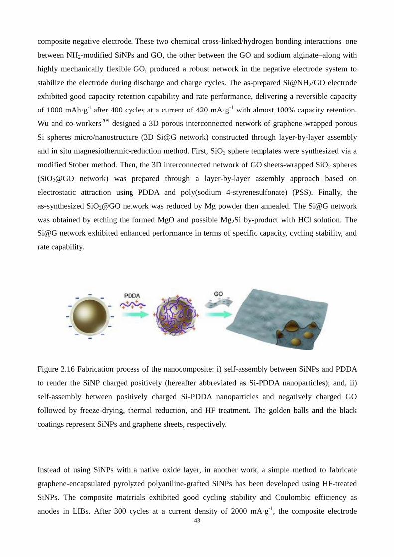
43
composite negative electrode. These two chemical cross-linked/hydrogen bonding interactions–one
between NH2-modified SiNPs and GO, the other between the GO and sodium alginate–along with
highly mechanically flexible GO, produced a robust network in the negative electrode system to
stabilize the electrode during discharge and charge cycles. The as-prepared Si@NH2/GO electrode
exhibited good capacity retention capability and rate performance, delivering a reversible capacity
of 1000 mAh·g-1
after 400 cycles at a current of 420 mA·g-1
with almost 100% capacity retention.
Wu and co-workers209
designed a 3D porous interconnected network of graphene-wrapped porous
Si spheres micro/nanostructure (3D Si@G network) constructed through layer-by-layer assembly
and in situ magnesiothermic-reduction method. First, SiO2 sphere templates were synthesized via a
modified Stober method. Then, the 3D interconnected network of GO sheets-wrapped SiO2 spheres
(SiO2@GO network) was prepared through a layer-by-layer assembly approach based on
electrostatic attraction using PDDA and poly(sodium 4-styrenesulfonate) (PSS). Finally, the
as-synthesized SiO2@GO network was reduced by Mg powder then annealed. The Si@G network
was obtained by etching the formed MgO and possible Mg2Si by-product with HCl solution. The
Si@G network exhibited enhanced performance in terms of specific capacity, cycling stability, and
rate capability.
Figure 2.16 Fabrication process of the nanocomposite: i) self-assembly between SiNPs and PDDA
to render the SiNP charged positively (hereafter abbreviated as Si-PDDA nanoparticles); and, ii)
self-assembly between positively charged Si-PDDA nanoparticles and negatively charged GO
followed by freeze-drying, thermal reduction, and HF treatment. The golden balls and the black
coatings represent SiNPs and graphene sheets, respectively.
Instead of using SiNPs with a native oxide layer, in another work, a simple method to fabricate
graphene-encapsulated pyrolyzed polyaniline-grafted SiNPs has been developed using HF-treated
SiNPs. The composite materials exhibited good cycling stability and Coulombic efficiency as
anodes in LIBs. After 300 cycles at a current density of 2000 mA·g-1
, the composite electrode

44
delivered a specific capacity of ~900 mAh·g-1
with ~76% capacity retention.210
In another interesting work, a multilayered structural Si-RGO electrode was synthesized from bulk
Si particles through inexpensive electroless chemical etching to obtain porous macro Si particles
and graphene self-encapsulating approach governed by electrostatic interaction. The prepared
composite electrode delivered a reversible capacity of 2787 mAh·g-1
at a charging rate of 100
mA·g-1
, and a stable capacity over 1000 mAh·g-1
at 1000 mA·g-1
after 50 cycles.19
Chang et al.211
developed a binder-free Si-based anode through encapsulation of SiNPs with carbon coating and
RGO coating, where CNT rooted from a nickel foam resulted in a strong connection mechanically
and electrically between active materials and current collectors. In the resulting architecture shown
in Figure 2.17, a dense cellular carbon coating from carbonization of poly(methyl methacrylate)
(PMMA) on Si surfaces improved the electrical conductivity and accommodated the volume change,
whereas RGO networks provide additional mechanical strength to maintain the integrity of
electrodes. The nanostructure exhibited a reversible capacity up to 2700 mAh·g-1
at 0.05 C (130
mA·g-1
) and 70% of capacity retention (up to 1311 mAh·g-1
) at 2600 mA·g-1
after 900 cycles.
Figure 2.17 Schematic of the fabrication process for hybrid nanostructures. (a) A nickel foam
substrate. (b) CVD growth of CNTs on nickel foams. (c) Mixture of Si NPs and GO suspension in

45
ethanol. (d) Addition of PMMA into the mixed solution. (e) Deposition of GO/Si/PMMA mixtures
onto the CNT-coated nickel foam and (f) thermal annealing at 700 °C for 4 h.
2.6 Separator
A separator is a porous membrane placed between electrodes and soaked in electrolyte, which is
permeable to ionic flow but preventing electronic contact between the electrodes. Another important
function of separator is a shutter action to stop the mass transfer in the case of accidental heat
generation, which cause it melt down, resulting in shut down of a cell. Separators should be very
good electronic insulators and have the capability of conducting ions by either intrinsically being an
ionic conductor or by soaking an electrolyte. They should minimize any processes that adversely
affect the electrochemical energy efficiency of the batteries. The material should be soft and flexible
enough to act as buffer between the both sheets of cathode and anode. The material should also be
sufficiently stable for a long time because it is directly in contact with the electrolyte all the time.212
A variety of separators have been used in batteries over the years. Starting with cedar shingles and
sausage casings, separators have been manufactured from cellulosic papers and cellophane to
nonwoven fabrics, foams, ion exchange membranes, and microporous flat sheet membranes made
from polymeric materials. Currently, the most commonly used separators for LIBs are polyolefin
membranes, which are made of polyethylene (PE), polypropylene (PP), or laminates of PE and PP.
They are made up of polyolefin materials because they provide excellent mechanical properties,
chemical stability, and acceptable cost. They have been found to be compatible with the cell
chemistry and can be cycled for several hundred cycles without significant degradation in chemical
or physical properties.34
As batteries have become more sophisticated, highly-performance separator
has also become more demanding. A wide variety of properties are required of separators used in
batteries,212, 213
including:
(1) Electronic insulator;
(2) Minimal electrolyte (ionic) resistance;
(3) Mechanical and dimensional stability;
(4) Sufficient physical strength to allow easy handling;
(5) Chemical resistance to degradation by electrolyte, impurities, and electrode reactants and
products;
(6) Effective in preventing migration of particles or colloidal or soluble species between the two
electrodes;

46
(7) Readily wetted by electrolyte;
(8) Uniform in thickness and other properties.
2.7 Electrolyte
A mixture of aprotic organic solvents is typically used in commercial LIBs, including cyclic and
linear alkyl carbonates such as ethylene carbonate (EC), dimethyl carbonate (DMC), diethyl
carbonate (DEC), ethyl methyl carbonate (EMC) and propylene carbonate (PC). The solvent
composition is chosen to achieve a balance between viscosity, the ability of the solvent to form a
stable passivation layer, and sufficiently high dielectric constant to dissolve lithium salts such as
lithium hexafluorophosphate (LiPF6) or lithium perchlorate (LiClO4). The operating potential of the
anode in lithium cells is close to that of metallic lithium, which lies outside of the thermo-dynamic
stability region of organic electrolytes. Therefore, the electrolyte solution undergoes
electrochemical decomposition, resulting in the formation of a SEI layer, which prevents electron
travelling between the electrolyte and electrode, and maintains kinetic stability outside of the
solvent potential window.32
Electrolyte is actually the main component determining the current (power) density, the time
stability, and the safety of a battery. Taking it into account that the electrolyte is in intimate contact
with the two electrodes, a good chemical and physical compatibility with both the electrodes is
required in order to obtain a stable electrified interface (EI) and, consequently, energy and power
density values stabilized with time. In spite of a wide variety of liquid electrolytes developed during
the 1990s, many LIBs preferentially chose some optimized formulations, which consist of proper
concentrations of LiPF6 in a mixture of EC and a linear alkyl carbonate.214
An ideal electrolyte solvent for LIBs shall meet the following minimal criteria, namely, high
dielectric constant, ability to dissolve salts of sufficient concentration, low viscosity for facile ion
transport, inert to all cell components, especially the charged surfaces of the electrodes, low melting
point, and high boiling point to remain in liquid phase in a wide temperature range.
An ideal electrolyte solute in LIBs completely dissolves and dissociate, in the nonaqueous media,
and the solvated ions should be able to move in the media with high mobility. The electrolyte solute
should be stable against oxidative decomposition at the positive electrode, should be inert to
electrolyte solvents and other cell components, and should be nontoxic and remain stable against
thermally induced reactions with electrolyte solvents and other cell components.212

47
2.8 Summary and perspectives
There is no doubt that great markets exist for higher energy density batteries and increasing
research efforts to develop high-power and high-capacity LIBs. Current commercial LIBs are
limited by the capacity of their electrode materials. Although Si possesses the highest specific
capacity as anode material for LIBs, development of Si to replace graphite faces several hurdles;
most notably, the volume changes of Si during Li+ intercalation and de-intercalation causes cracking
and pulverization of the active material. Nano-sized Si has proven to be successful in overcoming
mechanical degradation, providing a good substrate adhesion and allowing for shorter lithium
diffusion distances. But Nano-sized Si is easy to aggregate and large surface area leads to massive
SEI growth, causing heavy irreversible capacities.
Graphene has shown growing research attentions since it was given birth. Graphene as an anode for
LIB can store more lithium ions than graphite because lithium ions can not only be stored on both
sides of graphene sheets, but also on the edges and covalent sites. Graphene as coating layer for Si
is also attractive because graphene is electrically conducting and mechanically strong. Various
fabrication methods have been developed for graphene and its derivatives preparation, and
approaches for the synthesis of high-quality graphene in large scale at low price are required.
Recent works have shown surface coating, surface modification and good structure design of
Si-based anode are effective protocols to improve the electrode performance. As development of Si
anodes continues to extend the cycle life and improve high-rate performance, it may not be long
before these high-capacity Si anodes find their way into practical applications.
2.8 References

48
Chapter 3 Research methodology
This chapter describes the experimental setup and technical theories. The designed materials were
synthesized, characterized and electrochemically tested in the laboratory. Electrode preparation
technique and material characterization protocols are introduced in this chapter. The battery
assembly procedure and electrochemical testing details are also presented.
3.1 Preparation of GO
Natural graphite flake (325 mesh, 5.0 g) and NaNO3 (2.5g) are mixed with 120 ml H2SO4 (95 %) in
a 500 ml flask. Within ice bath, stir the mixture for 30 min. Under vigorous stirring, potassium

49
permanganate (15.0 g) is carefully added little by little to the suspension. The temperature of the
reactants should be controlled below 20 °C and keep stirring overnight. Then 150 ml H2O is slowly
added under vigorous stirring and the temperature quickly rises to 98 °C, meanwhile the color of the
suspension changes to yellow. Keep stirring for one day and add 50 ml of 30 % H2O2 slowly. To
purify the product, the mixture is washed by rinsing and centrifugation with 5 % HCl then
deionized (DI) water for several times. Dry the purified GO and store it in a dry tower for further
research.
3.2 Anode materials preparation
See the following chapters for details.
3.3 Fabrication of coin cell batteries
A manual cutter is used to cut the anode disks with a diameter of 15 mm. The CR2032 coin cells are
assembled in glovebox (MBraun Company, Germany, Figure 3.1) under ultra-pure Ar atmosphere.
Scheme 3.1 demonstrates the schematic diagram of a typical used CR2032 coin cell in this project.
A metallic Li disk (99.9% purity, 200um thick, 15mm diameter) is chosen as the counter electrode
and 1 M LiPF6 in ethylene carbonate (EC) : Diethyl carbonate (DEC) : dimethyl carbonate (DMC)
1:1:1 w/w will be used as electrolyte. A sheet of circular polyethylene (PE) membrane, whose
diameter is a little larger than the electrodes, will be placed between the two electrodes as separator.
A steel disk as spacer and a wave spring are employed between the anode and the negative cell shell
to make sure a close contact of each component. After assembly using a crimping machine (MTI
company, China), the prepared coin cells are placed aside for 24 hours and then undergo
electrochemical testing.

50
Figure 3.1 Glove box system MBraun-unilab (1200/780)
Scheme 3.1 Illustration of coin cell battery fabrication.
3.4 Electrochemical measurements
To test the electrochemical performances of the prepared anode disks, below measuring protocols

51
are chosen to be conducted including the galvanostatic charge-discharge test, Cyclic Voltammetry
(CV) and Electrochemical Impedance Spectroscopy (EIS) tests.
Charge-discharge Test
Cycling testers from Neware Company (Figure 3.2) are used to test the cycling performances of the
coin cells at constant current in a setting voltage range for RGO and Si@RGO composite materials.
Charging and discharging capacities are tested at a constant current density between the voltages
from 0.005 to 3.500 V and from 1.20 to 0.01 V for carbon materials and Si@RGO composites,
respectively.
Figure 3.2 BTS-5V1mA battery testing equipment
Cyclic Voltammetry
CV curves are recorded with a CHI660D electrochemistry workstation (Figure 3.3). CV
measurement is an electrochemical technique applied to record the current development in an
electrochemical cell when the potential at the working electrode is ramped linearly with time in the
set potential range. The same type of coin cells are used for the CV analysis as that for the cycle and
rate capability tests with lithium metal as the counter and reference electrodes.
Electrochemical Impedance Spectroscopy

52
EIS measurements of coin cells with metallic lithium as both counter and reference electrode are
taken at room temperature with CHI660D electrochemistry workstation over the frequency range
100 kHz to 10 mHz, and the signal amplitude is 5 mV. EIS measurement is used to study the
reaction mechanism of electrochemical process. The rate determining step can be revealed by the
frequency response shown by EIS test because different reaction steps will dominate at certain
frequencies. The variation of resistance can be examined by monitoring the current response. The
obtained impedance Nyquist curve of the testing battery is made up by a depressed semicircle in the
high-frequency region representing the resistance of the SEI film and the charge-transfer resistance,
a straight line in the low-frequency region corresponding to the diffusion of Li+.
Figure 3.3 CHI660D electrochemical workstation
3.5 Materials Characterization
In order to achieve comprehensive study of the prepared anode materials, the widely used
morphology characterization method is electron microscopy.
A scanning electron microscope (SEM) is a type of electron microscope that produces images of a
sample by scanning it with a focused beam of electrons. The electrons interact with atoms in the
sample, producing various signals that contain information about the sample's surface topography
and composition. The electron beam is generally scanned in a raster scan pattern, and the beam's
position is combined with the detected signal to produce an image. SEM can achieve resolution
better than 1 nanometer.

53
The most common SEM mode is detection of secondary electrons emitted by atoms excited by the
electron beam. The number of secondary electrons that can be detected depends, among other things,
on the angle at which beam meets surface of specimen, i.e. on specimen topography. By scanning
the sample and collecting the secondary electrons that are emitted using a special detector, an image
displaying the topography of the surface is created.
Apart from SEM, below are necessary strategies and instruments utilized in the research:
(1) Scanning electron microscopy (SEM, JEOL 6610, JEOL 7001 and JEOL 7800F at 5.0 kV)
(2) Transmission electron microscopy (TEM, Philips Tecnai F20 and Philips Tecnai F30 at 200
kV)
(3) High-resolution transmission electron microscopy (HRTEM, Philips Tecnai F30 at 200kV)
(4) Energy-dispersive X-ray spectroscopy analysis (EDX, JSM6610 EDS system)
(5) X-ray photoelectron spectroscopy (XPS, Kratos Axis ULTRA, using a monochromatic Al
Ka (1486.6 eV) X-ray source and a 165 mm hemispherical electron energy analyzer)
(6) X-ray diffraction (XRD, German Bruker D8 Advanced X-Ray Diffractometer with Ni
filtered Cu Kα radiation (40 kV, 30 mA))
(7) Raman Spectroscopy (Thermo-Fischer Almega dispersive Raman instrument fitted with
both 633 and 785 nm lasers)
(8) N2 adsorption/desorption isotherms (Tristar II 3020)
(9) Thermogravimetric analysis (TGA, DTG-60A system under air flow)

54
Chapter 4 Stabilization of Silicon
Nanoparticles in Graphene Aerogel
Framework for Lithium Ion Storage

55
4.1. Introduction
With the fast growing demands for energy storage devices, the development of new-generation
LIBs is becoming increasingly important. Achieving high capacity, excellent cycling performance
and rate capability with innovative electrode materials has been one of the main challenges.32
Silicon (Si) is a promising anode material for new-generation LIBs because of its high theoretical Li
ion storage capacity (∼4200 mAh·g-1), significantly higher than that of commercialized graphite
(372 mAh·g-1). Si also features low discharge potential (~0.4 V vs Li/Li
+), rich natural abundance,
and environmental benignity.7, 8, 9
However, the realization of Si as a LIB anode has been hindered
because Si suffers from not only a low intrinsic electronic conductivity but also a large specific
volume changes (>300%) during lithiation and delithiation, resulting in pulverization of Si particles
and electrical disconnection from the current collector, leading to a rapid capacity fading. 10, 11, 12
To
solve these problems, nanostructured Si electrodes such as nanoparticles, 9, 200, 215, 216
nanowires, 217,
218, 219, 220, 221 nanotubes and hollow spheres
189, 222 have been explored. Combining SiNPs with
carbon materials has also been studied. 24, 200, 216, 223, 224, 225, 226, 227
Graphene, a monolayer of carbon atoms arranged in a two-dimensional (2D) honeycomb network,
has been used to improve the stability and electric conductivity of nanostructured Si electrodes for
LIBs. 15
Due to its high electronic conductivity, superior mechanical strength and flexibility,
graphene can improve electron transport and Li+ diffusion, thus enhancing the electrochemical
performance of SiNPs for lithium ion storage. 24, 25, 26, 27
In spite of the observed improvement of the
electrochemical performance of SiNPs by graphene, SiNPs still tend to aggregate. As a result, the
performance of the graphene-SiNPs composites inevitably degrades during charge/discharge.
Recently, three-dimensional (3D) graphene materials, including hydrogels and aerogels, have been
shown to possess advantages, such as high surface area and good electrical conductivity. 228, 229, 230
These 3D graphene materials may be favourable for stabilizing SiNPs.
This work describes a method for preparing graphene-stabilized SiNPs on the basis of electrostatic
interactions. Because both graphene oxide (GO) and SiNPs (there is a thin layer of SiO2 on the
surface of the SiNPs) are negatively charged in a wide pH range, the SiNPs used in this work were
firstly modified using poly(diallydimethylammonium chloride) (PDDA, a positively charged
polyelectrolyte) to change the surface charge nature from being negative to being positive following
a protocol described elsewhere.24
As schematically illustrated in Scheme 4.1, the PDDA-modified
SiNPs interacted strongly with negatively charged GO sheets to form a Si-GO composite

56
(hereinafter designated as Si@GO). Because of the flexibility of GO sheets, SiNPs were wrapped in
by the GO sheets. The GO in the Si@GO suspension was then reduced using gallic acid (GA, a
natural plant phenolic acid) in an oil bath at 95 °C for 4 h. It has been reported that in the presence
of natural phenolic acid, GO can be reduced to assemble into RGO hydrogels driven by the
enhancing hydrophobicity and π–π interactions among the nanosheets during the reduction. 228, 231
During this GA reduction process, yellow-brown-coloured Si@GO suspension gradually turned
transparent to form a dark grey gel separating from the suspension, indicating that the GO had been
reduced to reduced graphene oxide (RGO) and the SiNPs had been wrapped by the RGO
architecture. In order to understand the stabilization effect of RGO sheets on SiNPs, the obtained
Si@RGO hydrogel was crushed and redispersed in an aqueous GO suspension, which was further
reduced with GA at 95 °C for 12 h. After freeze-drying and thermal reduction at 700 °C for 2 h
under H2/Ar atmosphere, a black 3D RGO aerogel with confined SiNPs, designated as Si/RGO-AG,
was obtained. For comparison purpose, another two samples were prepared. One, designated as
Si/RGO, was prepared by mixing SiNPs with aqueous GO suspension, followed by filtration
separation and thermal reduction at 700 °C for 2 h under H2/Ar atmosphere. The other one,
designated as Si/RGO-SWAG with SiNPs entrapped in RGO single-step wrapping aerogel
framework, was prepared according to the procedure of preparing sample Si/RGO-AG without Step
3 (see Experimental Section for details).
Scheme 4.1 Schematic illustration of the preparation of Si/RGO-AG: 1) surface modification of

57
SiNPs with PDDA; 2) formation of Si@GO composite via electrostatic interactions; 3) reduction of
Si@GO using GA to form Si@RGO hydrogel; 4) dispersing Si@RGO in a GO suspension for
further reduction using GA.
4.2 Experimental
Preparations of graphene oxide (GO)
The GO used in this work was prepared from natural graphite flake (Sigma Aldrich, 325 mesh) by
using a modified Hummers method. 232
Preparation of RGO aerogel wrapped SiNPs (Si/RGO-AG)
SiNPs (120 mg, 99% purity, from Nanostructured & Amorphous Materials, Inc.) and 20wt% PDDA
(3.0 g, Sigma Aldrich, MW = 10000-20000) aqueous solution were dispersed in water (120 mL)
under sonication in a water bath (KQ3200DE, 40 kHz). Excess PDDA was washed away by
centrifugation (10000 rpm) four times, followed by vacuum drying. An aqueous GO suspension (15
mL, 2 mg·mL-1
) was centrifuged at 5000 rpm for 30 min to remove any graphite particles and then
mixed with the above PDDA-modified SiNPs (120 mg) under sonication for 1 h. After the addition
of GA (13 mg), the mixed suspension was transferred to a 20 mL capped vial and placed into an oil
bath at 95 °C for 4 h to form a Si@GO hydrogel. The hydrogel was collected and redispersed in
another GO aqueous suspension (15 mL, 2 mg·mL-1
) and GA (13 mg) under sonication. The
suspension was then transferred into a 20 mL vial to prepare hydrogel at 95 °C for 12 h. The
resulting hydrogel monolith was soaked in distilled water, followed by freeze-drying. Reduction
was conducted in a quartz tube at 700 °C for 2 h under a H2/Ar (5:95 v/v) atmosphere with a
heating rate of 2 °C min-1
to obtain sample Si/RGO-AG.
Preparation of other samples
For comparison purpose, another two samples were prepared. One of them, designated as Si/RGO,
was prepared as follows. An aqueous GO suspension (30 mL, 2 mg·mL-1
) was mixed with
PDDA-modified SiNPs (120 mg) under sonication for 1 h. After the addition of GA (26 mg), the
suspension was reduced at 95 °C in an oil bath for 12 h under magnetic stirring. Then the solid was
collected by filtration, followed by vacuum drying and reduction in a quartz tube at 700 °C for 2 h

58
under a H2/Ar (5:95 v/v) atmosphere with a heating rate of 2 °C min-1
. The other sample, designated
as Si/RGO-SWAG, was prepared as follows. An aqueous GO suspension (15 mL, 2 mg·mL-1
) was
mixed with PDDA-modified SiNPs (60 mg) under sonication for 1 h. After the addition of GA (13
mg), the suspension was transferred into a 20 mL capped vial and placed in an oil bath at 95 °C for
12 h. The resulting hydrogel monolith was soaked in distilled water, followed by freeze-drying.
Reduction was conducted in a quartz tube at 700 °C for 2 h under an H2/Ar (5:95 v/v) atmosphere
with a heating rate of 2 °C min-1
.
Characterization
The TEM and HRTEM measurement was performed on a Philips Tecnai F20 and Philips Tecnai
F30 field emission transmission electron microscopes operated at 200 kV. SEM images were
obtained from a JEOL 7800F scanning electron microscope operated at 5.0 kV. XRD patterns were
collected on a German Bruker D8 Advanced X-Ray Diffractometer with Ni filtered Cu Kα radiation
(40 kV, 30 mA). Thermo gravimetric analysis (TGA) was carried out on a TGA/DSC1 STARe
System under air flow (25-900 ºC, 5 ºC/min). X-ray photoelectron spectra (XPS) were collected on
a Kratos Axis ULTRA X-ray photoelectron spectrometer using a monochromatic Al Ka (1486.6
eV) X-ray source and a 165 mm hemispherical electron energy analyzer. Nitrogen physisorption
isotherms were measured at 77 K on Tristar II 3020. All samples were degassed at 200 °C for 12 h
prior to the measurements. The specific surface areas of the samples were calculated using the
Brunauer–Emmett–Teller (BET) method and the total pore volumes were estimated from the
nitrogen volumes adsorbed at the relative pressure of 0.99. The pore size distribution curves were
derived from the Barrett-Joyner-Halenda (BJH) method of isotherm analysis. Raman spectra were
collected on a Thermo-Fischer Almega dispersive Raman instrument. The instrument was fitted
with both 633 and 785 nm lasers. Energy-dispersive X-ray spectroscopy analysis (EDX) was
conducted on a JSM6610 EDS system.
Electrochemical measurements
The electrochemical properties of the prepared samples were evaluated with CR2032 coin cells. The
electrodes were prepared by mixing the active materials with conductive carbon black (Super-P)
and poly(vinylidene fluoride) (PVDF) dissolved in N-methyl-2-pyrrolidone (NMP) with a mass
ratio of 80:10:10 to form a homogeneous slurry under magnetic stirring. The slurry was then spread
onto a pure Cu foil. Pure lithium metal discs were selected as the counter electrode. The electrolyte
used was 1 M LiPF6 in ethylene carbonate/dimethyl carbonate (1:1 v/v). A Celgard 2400
microporous polypropylene membrane was used as the separator. The CR2032 cells were

59
assembled in an argon-filled glove box (Mbraun Unilab) with water and oxygen contents less than 1
ppm. Cyclic voltammetry was carried out on a CHI 660D electrochemical workstation at a scan rate
of 0.1 mV·s-1
. The discharge and charge measurements of the batteries were performed on a
Neware system in the fixed voltage window between 0.02 and 1.20 V at room temperature.
4.3 Results and discussion
The morphology and microstructure of the Si/RGO-AG composite were characterized using
scanning electron microscopy (SEM), transmission electron microscopy (TEM) and high-resolution
TEM (HRTEM) techniques. The HRTEM image in Figure 4.1 shows that there was a shell around
the SiNPs with a thickness of about 5 nm. The X-ray photoelectron spectroscopy (XPS) results of
the SiNPs in Figure 4.2 shows a peak at 103 eV, which is attributed to Si 2p electrons in Si-O4,233
confirming the shell was silicon oxide (SiO2). This SiO2 layer plays a vital role in modifying the
surface chemistry of SiNPs. 24
The silanol groups on the surface of the SiO2 shell can be ionized
under the experimental conditions to carry a negative charge, thus enabling strong electrostatic
interactions between the SiNPs and PDDA to change the SiNPs from a negatively charged surface
to a positively charged surface. On the other hand, according to a recent study, 234
the SiO2 layer
can suppress the volume expansion of SiNPs although it consumes some lithium ions during the
first discharge cycle.
Figure 4.1 HRTEM image of SiNPs used in this work.
B

60
Figure 4.2 XPS survey (A) and Si 2p spectrum of SiNPs (B).
Figures 4.3A and 4.3B are the SEM images of Si/RGO-AG under different magnifications. SiNPs
with an average diameter of 100 nm dispersed the 3D RGO aerogel framework can be clearly seen.
On contrast, severe aggregation of SiNPs can be observed from pure SiNPs (Figure 4.4A), sample
Si/RGO (Figure 4.4B) and sample Si/RGO-SWAG (Figure 4.4C, 4.4D). In particular, the SiNPs in
sample Si/RGO formed micro-sized aggregates. After a single-step wrapping by RGO, the
aggregation of SiNPs was not significant. However, some SiNPs were not fully wrapped by RGO
and aggregates can be still observed. This explains the capacity fading of sample Si/RGO-SWAG.
The elemental analysis results of Si/RGO-AG (Figure 4.5) confirmed the existence of major

61
elements Si and C and their homogeneous distribution in the 3D aerogel. In this Si/RGO-AG
composite, the graphene aerogel provides a porous network for the entrapped SiNPs, thus is
beneficial for accommodating the volume change of these SiNPs during electrochemical reactions.
The porous network also facilitates electrolyte transport, potentially enhancing the rate capacity of
LIBs. Besides, the continuous interconnected graphene network creates favourable electron
pathways against cycling processes. The HRTEM image shown in Figure 4.1C also clearly
demonstrates the existence of a continuous RGO network with SiNPs entrapped. The HRTEM
image in Figure 4.1D shows that SiNPs were well-encapsulated within the RGO aerogel network
Figure 4.3 SEM (A, B), TEM (C), and HRTEM images (D) of Si/RGO-AG composite.
A
D C
B
SiNP
RGO
RGO
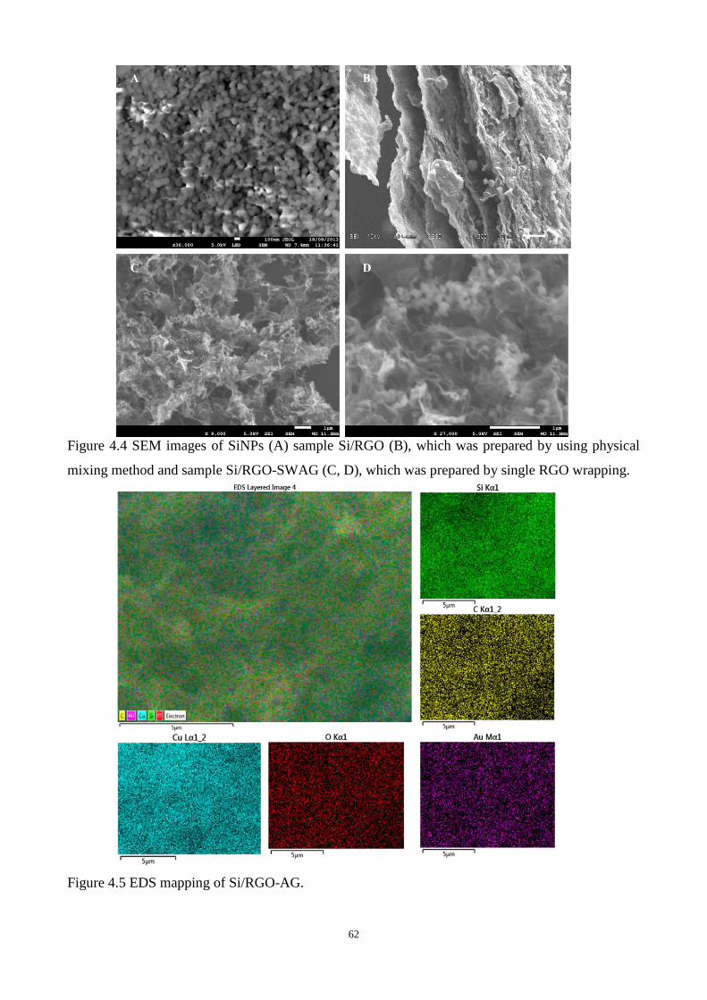
62
Figure 4.4 SEM images of SiNPs (A) sample Si/RGO (B), which was prepared by using physical
mixing method and sample Si/RGO-SWAG (C, D), which was prepared by single RGO wrapping.
Figure 4.5 EDS mapping of Si/RGO-AG.

63
Figure 4.6 shows the X-ray diffraction (XRD) patterns of Si/RGO-AG and SiNPs. All diffraction
peaks due to SiNPs can be seen from sample Si/RGO-AG, indicating that the silicon crystalline
structure in the Si/RGO-AG composite retained after the freeze-drying and thermal reduction
treatments.
Figure 4.6 XRD patterns of SiNPs and Si/RGO-AG.
Figure 4.7 presents the Raman spectra of Si/RGO-AG and pristine SiNPs. The absorption bands due
to SiNPs can be seen from Si/RGO-AG, confirming the presence of crystalline Si particles in the
composite. There are two more absorption bands at 1350 and 1596 cm-1
, respectively. These two
peaks are assigned to the D band and G band of graphene, respectively, 235
confirming the presence
of RGO in the composite.
Figure 4.8 presents the C1s XPS spectra of samples. As can be seen, GO showed three peaks at
284.9, 286.8, and 289.0 eV, corresponding to C=C in aromatic rings, C-O-C in epoxy and alkoxy,
and C=O in carbonyl and carboxyl groups, respectively. It is clearly seen that the peak intensity due
to C-O-C and C=O bonds of sample Si/RGO-AG is significantly lower than that of sample GO. The
intensity of the peak ascribed to C=C however increased after reduction. These data suggest that the
oxygen-containing groups on GO were largely removed, and most of the conjugated bonds were
restored by GA reduction and thermal treatment.

64
Figure 4.7 Raman spectra of SiNPs and Si/RGO-AG.
The N2 adsorption/desorption isotherms of the Si/RGO-AG composite (see Figure 4.9A) showed a
type IV isotherm with an H3 hysteresis loop, indicating a mesoporous structure of the material. The
Brunauer-Emmett-Teller (BET) surface area and pore volume of the composite was measured to be
125 m2/g and 0.37 cm
3/g, respectively, much higher than that of pure SiNPs (25 m
2/g and 0.055
cm3/g, respectively, see Figure 4.9B). The Barrett-Joyner-Halenda (BJH) pore size distribution
curve of Si/RGO-AG (see Figure 4.9C) demonstrates that Si/RGO-AG composite had a mesoporous
structure with two pore systems. The intensive peak around 5.0 nm is due to the presence of small
gaps among randomly stacked graphene sheets, while the broad peak centred at about 26 nm may
be due to the large voids between inter-twisted graphene sheets. 236
The high surface area along
with the existence of mesopores in Si/RGO-AG should offer a large material-electrolyte contact
area and promote the diffusion of Li+ ions if Si/RGO-AG is used as electrode materials for lithium
storage.
Thermal gravimetric analysis (TGA) was carried out in air and the results are shown in Figure 4.9D.
It can be seen that the mass of the pristine SiNPs increased slightly with a mass gain of about 0.150
wt% at 700 °C. This gain was due to the oxidation of Si by O2 to form SiO2. At 700 °C, the residual
of the RGO aerogel was about 3.02 wt%, which was due to the impurities in the GO sample. The
weight loss of the Si/RGO-AG composite at 700 °C was about 19.3 wt%. Based on the TGA data,
the Si/RGO-AG composite was calculated to contain about 80.0 wt% SiNPs and 20.0 wt % RGO
aerogel.

65
Figure 4.8 C 1s XPS spectra of GO (A) and Si/RGO-AG (B).

66
Figure 4.9 N2 adsorption/desorption isotherms (A) and BJH pore size distribution based on
desorption isotherm of Si/RGO-AG (B). N2 adsorption/desorption isotherm of SiNPs (C); TGA
curves for SiNPs, RGO aerogel and Si/RGO-AG conducted in air (D).
The electrochemical performance of the Si/RGO-AG composite as an anode was assembled and
tested in a CR2032 coin cell where lithium foil was used as a counter electrode. For comparison, the
cycling performance of electrode Si/RGO was also tested under the same experimental conditions.
Figure 4.10A shows typical cyclic voltammetry (CV) curves of electrode Si/RGO-AG in the
potential range of 0.02-1.20 V (vs Li+/Li) at a scan rate of 0.1 mV·s
-1 of the first two cycles, starting
at the open circuit potential of 1.59 V. A broad cathodic peak in the first cycle appeared at 0.69 V,
indicating the formation of solid electrolyte interphase (SEI).200
This cathodic peak disappeared in
the second cycle and correlated to an initial capacity loss. The main cathodic part of the second
cycle displayed a peak at 0.19 V, corresponding to the formation of Li-Si alloy phases. 237
The
anodic part showed two peaks at 0.34 and 0.52 V, corresponding to the phase transition from Li-Si
alloys to amorphous Si. 24, 200

67
Figure 4.10B displays the discharge/charge profiles of the initial three cycles of electrode
Si/RGO-AG under a current density of 150 mA·g-1
in the voltage window of 0.02 to 1.2 V (vs.
Li+/Li). The onset slope at about 0.7 V in the initial discharging curve, which disappeared in the
following cycles, corresponds to the SEI formation 200
. Besides, the main discharge plateau is
around 0.2 V and the charge plateau is around 0.5 V. All these features are in good agreement with
the CV results discussed above. The specific capacity was calculated based on the total mass of
Si/RGO-AG. The initial discharge/charge capacities were 3446 and 2535 mAh·g-1
, respectively, to
give an initial Coulombic efficiency of 73.6 %. The initial irreversible capacity of electrode
Si/RGO-AG can be attributed to the formation SEI, the unexpected reaction of the remaining
oxygen-containing groups in the RGO aerogel and SiO2 layer on the surface of SiNPs with Li ions.
27, 195 After the second cycle, the Coulombic efficiency tended to increase and stabilize. It is
interesting to note that the curves of the second and third cycles almost overlapped each other,
which indicates a good cycling stability of the electrode. The reversible capacities of the second and
third cycles compared with the first cycle were slightly increased, which can be attributed to the
activation of the SiNPs in the Si/RGO-AG composite.
Figure 4.10C shows the cycling performance of Si/RGO-AG at a current density of 150 mA·g−1
,
together with electrodes Si/RGO-SWAG and Si/RGO. It can be seen that the initial charge and
discharge capacities of electrode Si/RGO were the lowest among the three electrodes studied. This
poor performance of electrode Si/RGO was probably due to severe aggregation of the SiNPs,
indicating the RGO sheets did not stabilize the SiNPs well. After about 20 cycles, the reversible
capacity dropped drastically to about 450 mAh·g-1
, confirming that the SiNPs were not stabilized
well by the RGO sheets. These results suggest that the physical mixing method is not a good
approach to stabilizing SiNPs. While the initial discharge/charge capacities of electrode
Si/RGO-SWAG reached to 3360 and 2450 mAh·g-1
, respectively, its reversible capacity decreased
to about 615 mAh·g-1
after 40 cycles. The improved performance of electrode Si/RGO-SWAG
indicates the single-step wrapping method illustrated in Scheme 4.1 is advantageous over the
physical mixing method. This fast capacity fading however indicates that the single-step wrapping
method still could not afford efficient stabilization of SiNPs. On contrast, the Si/RGO-AG electrode
showed a significantly improved cycling performance with the highest initial charge/discharge
capacities and delivered a reversible capacity of 1984 mAh·g-1
after 40 cycles.
Figure 4.10D demonstrates the rate capability of the Si/RGO-AG at current densities ranging from
170 mA·g-1
to 2500 mA·g-1
. The battery delivered a reversible capacity of about 1000 and 600
mAh·g-1
at the current densities of 2000 and 2500 mA·g-1
, respectively. Furthermore, the capacity

68
reached around 2000 mAh·g-1
when the current density was decreased to 170 mA·g-1
after having
been cycled at higher current densities, indicating a good cycling stability of Si/RGO-AG.
Figure 4.10 (A) Cyclic voltammetry curves for Si/RGO-AG for the first two cycles; (B)
Galvanostatic discharge/charge profiles of the first three cycles; (C) cycling performance of
electrode Si/RGO-AG, Si/RGO-SWAG, and Si/RGO; (D) rate capability of electrode Si/RGO-AG.
2nd cycle
Delithiathion A
D C
B
Si/RGO-AG
Si/RGO
Si/RGO-SWAG
1st cycle
1st cycle
2nd and 3rd cycles Lithiathion

69
Figure 4.11 shows the SEM image of electrode Si/RGO-AG after 40 cycles. As can be seen, the
Si/RGO-AG composite maintained its integrity and porous structure. In addition, the SiNPs were
entrapped by the RGO framework, contributing to the significantly improved cycling performance
of Si/RGO-AG.
Figure 4.11 SEM image of Si/RGO-AG after 40 cycles.
The Nyquist plots of the Si/RGO-AG electrode are presented in Figure 4.12. The depressed
semicircle in the high-frequency region represents the resistance of the SEI film and the
charge-transfer resistance, while the straight lines in the low-frequency region corresponds to the
diffusion kinetics of lithium ions. No obvious impedance increase is observed after cycling due to
the stable SEI. The impedance decrease may be attributed to the gradual electrolyte transport into
the electrode and the increasing conductivity of the SiNPs after lithiation.
The improved cycle performance and enhanced rate capability of Si/RGO-AG can be attributed to
the following reasons: i) the Si/RGO-AG composite created sufficient space and efficiently
accommodated the drastic volume change of the entrapped SiNPs during cycling; ii) the
interconnected 3D RGO aerogel network maintained the integrity of the electrode structure,
prohibited the detachment of the SiNPs from the current collector and improved the electrical
conductivity of the electrode; iii) the existence of meso- and macro- pores provided an efficient
pathway for electrolyte transport and facilitated Li+ diffusion, thus enhancing the rate performance.

70
Figure 4.12 Electrochemical impedance spectroscopy (EIS) curves of Si/RGO-AG.
4.4 Conclusions
In conclusion, we have demonstrated an approach to preparing a high-performance LIB negative
electrode material by encapsulating SiNPs in 3D RGO aerogel. The RGO aerogel with a porous
network offers space for accommodating SiNPs, as well as facilitating electron and electrolyte
transport. The composite electrode delivered a stable cycling performance with a capacity of about
2000 mA h g-1
after 40 cycles, together with an excellent rate capability.

71
Chapter 5 Lithium-storage Properties of
Reduced Graphene Oxide Using Gallic
Acid as Reducing Agent

72
5.1 Introduction
Lithium-ion batteries (LIBs) are one of the most promising energy-storage systems. Graphite, a
conventional and commercialized anode material for LIBs has a theoretical capacity of about 372
mAh·g-1
, limiting the development of advanced LIBs for emerging technologies, such as smart
grids, electric vehicles, and solar energy. Graphene-based materials have been shown to have
tremendous potentials for a myriad of applications, including energy storage.28
In particular,
graphene as an anode for LIB can store more lithium ions than graphite because lithium ions can
not only be stored on both sides of graphene sheets, but also on the edges and covalent sites.15
To
move the graphene-based energy storage technology further, a scalable and ecofriendly technique to
produce large-quantity graphene is paramountly important.
Chemical reduction of graphene oxide (GO) is regarded as a feasible method for mass-production of
reduced graphene oxide (RGO). The most commonly used reductants are sodium borohydride and
hydrazine,29, 31, 238
which are toxic. Thus, alternative reducing methods are desirable. Zhao and
co-workers239
have demonstrated that urea is an effective reducing agent in removing
oxygen-containing groups from graphite oxide for restoring the conjugated electronic structure of
graphene. Other ecofriendly reducing agents, such as L-ascorbic acid and tea polyphenol, have also
been proved to reduce GO successfully.240, 241, 242
Gallic acid (GA), a natural organic acid with three adjacent hydroxyl groups located at its only
benzene ring, has recently been shown to possess considerable ability to reduce GO.243
It has also
been observed that phenolic compounds including GA can function as a stabilizer to prevent RGO
sheets from aggregation.243, 244, 245
In the present study, the electrochemical properties of GO
samples reduced by GA as anode material for LIB were investigated for the first time, and
compared with previously reported RGO-based anodes. The RGO anode material prepared in this
work showed a significantly improved electrochemical performance with a reversible capacity of
around 1280 mAh·g-1
after 350 cycles at a current density of 200 mA·g-1
and good rate capability.
The improvements are attributed to the fairly complete reduction of GO using GA, the stabilization
function of GA prohibited RGO sheets from aggregation thus created micron-sized disordered
porous RGO architecture, the nano-cavities between RGO sheets and edges of RGO sheets
contributed superior lithium storage.

73
5.2 Experimental
Synthesis of Graphene Oxide (GO)
GO was synthesized from natural graphite flake (Sigma Aldrich, 325 mesh) using a modified
Hummers method.232
.
Preparation of RGO
GA (13 mg) was dissolved in 20 mL of the above-prepared GO suspension (2 mg·mL-1
) under
sonication. The mixed suspension was transferred into a 20 mL capped vial and placed into an oil
bath at 95 °C under magnetic stirring for 12 h. The resulting black solids were collected after
removing the upper liquid phase. The collected granules were soaked in distilled water 7 times for 7
days and then frozen quickly with liquid nitrogen and lyophilized, followed by heat treatment in a
quartz tube at 700 °C for 2 h under a H2/Ar (5/95, v/v) with a heating rate of 5 °C min-1
to
eventually obtain Si@RGO composite.
Characterization
TEM measurement was performed on a Philips Tecnai F30 field emission transmission electron
microscope operated at 200 kV. SEM images were obtained from a JEOL 7001 scanning electron
microscope operated at 5.0 kV. XRD patterns were collected on a German Bruker D8 Advanced
X-Ray Diffractometer with Ni filtered Cu Kα radiation (40 kV, 30 mA). X-ray photoelectron
spectra (XPS) were collected on a Kratos Axis ULTRA X-ray photoelectron spectrometer using a
monochromatic Al Ka (1486.6 eV) X-ray source and a 165 mm hemispherical electron energy
analyzer.
Electrochemical measurements
The electrochemical properties of the prepared samples were evaluated using CR2032 coin cells.
The RGO electrodes were prepared by mixing the RGO with conductive carbon black (Super-P)
and poly(vinylidene fluoride) (PVDF) dissolved in N-methyl-2-pyrrolidone (NMP) with a mass
ratio of 80:10:10 to form a homogeneous slurry under magnetic stirring. The slurry was then spread
onto a pure Cu foil. Pure lithium metal foil was used as the counter electrode. The electrolyte was 1
M LiPF6 in ethylene carbonate/dimethyl carbonate (1:1, v/v). A Celgard 2400 microporous
polypropylene membrane was used as the separator. The CR2032 cell was assembled in an

74
argon-filled glove box (Mbraun Unilab) with water and oxygen contents less than 0.1 ppm. Cyclic
voltammetry (CV) measurements were carried out on a CHI 660D electrochemical workstation at a
scan rate of 0.1 mV·s-1
. Electrochemical impedance spectral measurements were also performed
using the CHI 660D electrochemical workstation over the frequency range 100 kHz to 10 mHz, and
the signal amplitude was 5 mV. The discharge and charge measurements of the batteries were
performed on a Neware system in the fixed voltage window between 0.005 and 3.5 V for RGO
anode.
5.3 Results and Discussion
Oxidative breakup of graphite was done to produce GO and GO dispersions were deoxygenated
using GA in a fairly straightforward process. The morphology and microstructures of the RGO
sample were obtained using field-emission scanning electron microscopy (FESEM) and
transmission electron microscopy (TEM).
Figures 5.1A and 5.1B show the FESEM images of sample RGO at different magnifications. Porous
micron-sized RGO particles with similar sizes can be seen. Form Figure 5.1B corrugated RGO
architecture can be seen. No significant stacking of RGO sheets was observed.
Figure 5.2A shows that XPS results of both the GO and RGO samples. A drastic decrease in the
oxygen content after reduction can be seen. It was estimated that the atom percentage of oxygen in
the RGO sample was about 2.0%, less than that in the GO sample (31.1%). Apart from the surface
adsorbed oxygen, it is interesting to note that the RGO prepared using GA as the reducing agent
contained minor oxygen content in comparison with other reported reducing agents, such as sodium
borohydride (15.9%),29
hydrazine hydrate (6.2%),246
and other reduction methods namely
microwave digestion (10.5%),143
microwave radiation then hydrazine hydrate reduction (4.2%),142
and mild thermal reduction (17.5%).247
The high-resolution C1s XPS spectra of GO and RGO are
shown in Figure 5.2B. The C1s spectrum of GO was deconvoluted with five peak components with
binding energies of 284.6, 285.1, 286.9 287.7 and 288.9 eV, corresponding to C=C (sp2), C–C (sp
3),
C–O (hydroxyl and epoxy), C=O (carbonyl), O–C=O (carboxyl), respectively.243, 244, 248
Meanwhile,
for the RGO sample, no obvious peaks belonging to oxygen containing groups were observed,
suggesting a fairly complete reduction of GO. Only one prominent C1s peak was observed at 284.8
suggesting the sp2 graphitic nature of the sample.

75
Figure 5.1 (A-B) FESEM images of RGO under different magnifications.

76
Figure 5.2 (A) Survey XPS patterns of GO and RGO; (B) C1s XPS patterns of RGO and GO.
Figure 5.3 shows the X-ray diffraction (XRD) patterns of samples. For the GO sample, a wide
diffraction peak catered at 9.8° corresponding to an interlayer spacing of 0.901 nm can be seen. The
graphite sample displayed a sharp peak at 26.5° (corresponding to an interlayer spacing of 0.335
nm). The XRD results indicated the presence of functional groups and the disordered layers after
oxidization and exfoliation. After reduction, a new broad peak appeared at around 26.1° for RGO,
corresponding to an interlayer spacing of 0.340 nm fairly close to that of graphite. The new broad
peak suggests the removal of oxygen containing functionalities and the partially restoration of the
conjugate sp2 networks in the porous RGO network during the reduction of GO.
152, 245

77
Figure 5.3 XRD patterns of RGO, GO and graphite.
Figure 5.4 shows the Raman spectra of samples. The pristine graphite displayed a prominent G peak
(corresponding to sp2 hybridizing carbon) at 1581 cm
−1, as well as a very small D peak (originating
from disordered carbon) at 1338 cm−1
. The G band of sample GO was broadened and shifted to
1598 cm−1
. The D band at 1342 cm−1
became more prominent, indicating the reduction in size of the
in-plane sp2 domains with more defects resulting from the extensive oxidation, thus generating a
large number of oxygen-containing groups. While the Raman spectrum of the RGO sample also
contained both G and D bands, the peak intensity ratio of the D band over the G band (ID/IG=1.12)
is higher than that of GO (ID/IG=0.993). This change in intensity ratio is due to the decrease in the
dimension of sp2 domains during reduction and increased graphitization.
248, 249

78
Figure 5.4 Raman spectra of RGO, GO, and graphite.
The electrochemical performances of the prepared RGO were tested in CR2032 coin cells. Lithium
foil was used as both counter and reference electrode. For comparison, graphite was tested under
the same experimental conditions as RGO. The specific capacity was calculated based on the mass
of RGO and graphite only, respectively.
Figure 5.5A shows the first three cyclic voltammetry (CV) curves of the RGO electrode at room
temperature in the potential range of 0.005 – 3.500 V (versus Li+/Li) at a scan rate of 0.1 mV·s
-1.
The CV curve of the first cycle was different from those of the subsequent cycles, especially for the
cathodic curve, a strong peak is observed at 0.7 V, which was resulted from the irreversible side
reactions on the electrode surfaces and interfaces due to the solid electrolyte interphase (SEI) film.
From the second cycle on, it is important to note that the CV curves almost overlapped, indicating
the stable and superior reversibility of RGO anode.
The discharge-charge profiles of RGO anode in the first 3 cycles are shown in Figure 5.5B. The
RGO anode delivered a specific capacity of 1762 mAh·g-1
in the initial discharging and a reversible
capacity of 844 mAh·g-1
in the first charging. The irreversible capacity could be associated with the
formation of the SEI layer in the first cycle. From the second cycle, the curves of RGO anode
showed no distinguishable plateaus, which can be attributed to the smaller crystallite structure, high
specific surface area and disorganized RGO architecture.139
It has been proposed that lithium ions

79
can be adsorbed on both sides of the graphene sheet that arranged like a ‘‘house of cards’’ in hard
carbons, leading to two layers of lithium for each graphene sheet, with a theoretical capacity of 744
mAh·g-1
through the formation of Li2C6. On the other hand, nano-cavities between RGO sheets due
to scrolling and crumpling could also contribute to the lithium storage.15
The cycling performances of RGO and graphite electrodes were examined at a current density of
200 mA·g-1
. In Figure 5.5C, the RGO electrode delivered a reversible initial discharging capacity of
844 mAh·g-1
and its reversible capacity maintained a stable rising trend from the 15th
cycle for RGO.
After 200 cycles, the reversible capacity still kept a rising trend overall but more fluctuant. At the
350th
cycle, the RGO anode delivered a reversible capacity of 1280 mAh·g-1
, which represented a
much superior performance than that of graphite anode. The possible reason for the fluctuant rising
trend of its reversible capacity is that the gradual activation process of lithium insertion active sites,
such as edge-type sites, nanopores due to the permeation of the electrolyte during repetitive
charging and discharging process. The stable SEI layer formed during the first cycle also prohibited
further side reactions.
Figure 5.5D exhibits the rate capability of RGO anode at the current densities from 100 to 2000
mA·g-1
. It could deliver reversible capacities of about 900, 950, 500, 450, 400 mAh·g-1
at the
current densities of 100, 200, 500, 1000 and 1500 mA·g-1
, respectively. Even at 2000 mA·g-1
, it
could still deliver a capacity of more than 350 mAh·g-1
. After cycled at higher current densities, it
could still maintain the reversible capacities when the current densities were lower down. It is
reasonable to believe that more edge sites on the RGO are beneficial to the improved capacity at
high current rates, and the porous structure is able to reduce diffusion length of lithium ions,
resulting in better rate capability and cycling performance. In addition, the strongly crumpled and
scrolled RGO sheet could also contribute to the structural buffer for the volume expansion during
the Li insertion/extraction.

80
Figure 5.5 (A) Cyclic voltammetry curves for RGO; (B) Galvanostatic discharge-charge profiles of
the first three cycles for RGO; (C) cycling performances of RGO and graphite at the current rate of
200 mA·g-1
; (D) rate capability of RGO composite.
Summarizing the above results of RGO anode, it is concluded that micron-sized RGO particles
reduced by GA delivered a reversible capacity of around 1280 mAh·g-1
after 350 cycles at the
current density of 200 mA·g-1
as well as good rate capability. The RGO showed superior battery
performances than the recent reported ones: highest specific capacity of 817 mAh·g-1
for over 100
cycles using hydriodic acid (HI) as reductant250
; reversible capacity of 800 mAh·g-1
after 100 cycles
at a current density of 200 mA·g-1
using thermal annealing procedure158
; reversible capacity of
about 600 mAh·g-1
after 100 cycles at a current density of 149 mA·g-1
using hydrazine (N2H4) as
reductant251
; first charge specific capacity of 933 mAh·g-1
at 50 mA·g-1
by a metal etching
method157
; reversible capacity of about 620 mAh·g-1
at 100 mA·g-1
after 100 cycles for a core–shell
structured porous carbon–graphene composite159
; first discharge capacity of 1069.3 mAh·g-1
at 100
mA·g-1
, 733.3 mAh·g-1
after 100 cycles by a microwave digestion reduced graphene oxide
method143
.

81
Table 5.1 compares the electrochemical performance of RGO materials prepared by using different
reducing methods. It can be seen that micron-sized RGO reduced by GA delivered not only high
reversible capacity but also exhibited long cycle life. It is worth pointing out that the RGO prepared
using GA as a reductant is among the few ecofriendly chemical reducing methods to prepare RGO
anode for lithium ion storage without doping or adding extra additives.
Table 5.1 Comparison of graphene anode materials prepared by reducing GO using various methods
Reducing method
Reversible
capacity
(mAh·g-1)
Cycle life
Capacity
retention
(%)
Current rate
(mA·g-1
)
Solvothermal treatment and
thermal reduction158
800 100 81.6 200
Hydrothermal treatment and
thermal reduction147
1053 130 186
Thermal reduction252
760 35 100
Thermal reduction145
~634 300 1000
Thermal reduction144
576 50 50
Carbothermal reduction253
~576 20 100
Microwave digestion
reduction143
~733 100 100
Microwave-induced thermal
reduction146
1002 50 93 40
Infrared irradiation induced
photothermal reduction254
755 50 ~60 100
Supercritical isopropanol
reduction255
1331 100 50
Supercritical alcohol
reduction150
652 40 50
Ascorbic reduction152
420 100 97 2000
Ethylenediamine (EDA)
reduction151
346 60 350

82
Hydrazine reduction251
~600 50 ~48 149
Hydrazine reduction148
460 100 71
GA reduction (This work) 1280 350 200
5.4 Conclusions
In summary, micron-sized RGO particles prepared by reducing GO using GA displayed a good
electrochemical performance when used as anode for LIBs with a reversible capacity of around
1280 mAh·g-1
after 350 cycles at a current density of 200 mA·g-1
as well as a good rate capability,
attributing to the fairly complete reduction of GO by GA, existence of the edge sites from the
defects of RGO, and the porous network structure formed.

83
Chapter 6 Silicon Nanoparticles
Encapsulated in Reduced Graphene Oxide
Framework as a Stable Anode for Lithium
Ion Storage

84
6.1 Introduction
The development of lithium ion batteries (LIB) with both high energy density and power density is
of great importance to meet the ever-growing demands for high power sources. Achieving high
capacity, excellent cycling performance and rate capability for both anode and cathode of a LIB is
the main challenge for the improvement of the electrochemical performance of this energy storage
device.32
Compared with carbon materials, especially graphite as anode for LIBs, silicon (Si) is
regarded as a promising anode material because of its large theoretical capacity for Li ion storage
(4200 mAh·g-1
) and low discharge potential. However, the severe volume change (> 400%) of bulk
Si leads to rapid capacity fading due to pulverization during repetitive lithiation and delithiation
processes. The rate capability of Si is limited by its poor intrinsic electric conductivity.10, 11
Two
approaches are usually taken to improve its electrode performance. One approach is to shorten the
electronic and ionic transport length by fabricating nanostructured Si, but SiNPs trend to aggregate
during treatment. The other approach is to increase the electron transport by conductive carbon
coating or adding conductive additives such as carbon nanotubes, graphene.13
Especially graphene
or RGO, with a few-layer two-dimensional honeycomb carbon structure, has great advantages for
its high electron mobility, huge specific surface area and superior electrical conductivity when
prepared meticulously.15
Although improvements have been achieved using graphene sheets to
stabilize SiNPs16, 17, 19, 20, 21, 22, 23, 209, 211, 256, 257
, it is still highly needed to explore a cost-efficient and
green way to prepare Si/graphene composite.
Recently, it has been reported that sodium alginate (SA) can produce an improved Si anode
performance because SA contains a large amount of carboxylic groups, leading to a great number of
possible binder-bonds for electrode materials. It also has excellent mechanical properties and no
interaction in electrolyte solvents, showing 50 times higher stiffness than PVDF.258, 259
In this work, a new approach to encapsulating SiNPs within reduced graphene oxide (RGO) for
stabilizing the SiNPs is described. The RGO was used to stabilize SiNPs to prepare Si@RGO
composite materials with different Si/GO mass ratios. It was found that the Si@RGO composite
with Si/GO mass ratio of 1:2 (Si@RGO 1:2) delivered reversible capacities of 1074 mAh·g-1
at the
5th
cycle and 900 mAh·g-1
at the 100th
cycle with a capacity retention of about 84% as well as
excellent rate capability. Well-dispersed SiNPs in numerous cluster forms were stabilized between
the RGO architecture. The continuous RGO sheets not only enhanced the electronic conductivity of

85
the electrode, but also created enough space to facilitate electrolyte transport. Results also showed
that sodium alginate was a good binder for the Si@RGO composite.
6.2 Experimental
Synthesis of Graphene Oxide (GO)
GO was synthesized from natural graphite flake (Sigma Aldrich, 325 mesh) using a modified
Hummers method.232
.
Preparation of Si@RGO composite
SiNPs were first modified by using PDDA. Briefly, 120 mg of SiNPs (Aldrich, 40-100 nm) was
added to 120 mL de-ionised water, followed by adding 3 g of a 20 wt% PDDA (Sigma Aldrich,
MW = 10000-20000) solution under sonication in a water bath (KQ3200DE, 40 kHz). Excess
PDDA was washed away using deionized water four times. The PDDA-modified SiNPs (20, 40, 80
mg) was added to 20 mL of the GO suspension (2 mg·mL-1
) under sonication for 1 h. After the
addition of GA (13 mg), the mixed suspension was transferred into a 20 mL capped vial and placed
into an oil bath at 95 °C under magnetic stirring for 12 h. The following treatments were the same
with those of RGO above.
Characterization
TEM measurement was performed on a Philips Tecnai F30 field emission transmission electron
microscope operated at 200 kV. FESEM images were obtained from a JEOL 7001 scanning
electron microscope operated at 5.0 kV. XRD patterns were collected on a German Bruker D8
Advanced X-Ray Diffractometer with Ni filtered Cu Kα radiation (40 kV, 30 mA). X-ray
photoelectron spectra (XPS) were collected on a Kratos Axis ULTRA X-ray photoelectron
spectrometer using a monochromatic Al Ka (1486.6 eV) X-ray source and a 165 mm hemispherical
electron energy analyzer. Raman spectra were collected on a Thermo-Fischer Almega dispersive
Raman instrument. The instrument was fitted with both 633 and 785 nm lasers.
Electrochemical measurements

86
The electrochemical properties of the prepared samples were evaluated using CR2032 coin cells.
For PVDF binder, the Si@RGO electrodes were prepared by mixing the active materials with
conductive carbon black (Super-P) and PVDF dissolved in N-methyl-2-pyrrolidone (NMP) with a
mass ratio of 80:10:10 to form a homogeneous slurry under magnetic stirring; For CMC and SA
binders, the Si@RGO electrodes were prepared by directly mixing Si@RGO composites with
carbon black (Super-P) and CMC or SA dissolved in de-ionised water with a mass ratio of 80:10:10
to form a slurry under magnetic stirring. The above slurries were then spread onto a Cu foil using
doctor’s blade method. Pure lithium metal foil was used as both counter and reference electrode.
The electrolyte was 1 M LiPF6 in ethylene carbonate/dimethyl carbonate (1:1, v/v). A Celgard 2400
microporous polypropylene membrane was used as the separator. The CR2032 cell was assembled
in an argon-filled glove box (Mbraun Unilab) with water and oxygen contents less than 0.1 ppm.
Cyclic voltammetry measurements were carried out on a CHI 660D electrochemical workstation at
a scan rate of 0.1 mV·s-1
. The discharge and charge measurements of the batteries were performed
on a Neware system in the fixed voltage window between 0.02 and 1.20 V for Si@RGO composites
at room temperature.
6.3 Results and Discussion
Thus the porous RGO architecture was also utilized to stabilize SiNPs as shown in Scheme 6.1. To
prepare Si@RGO composite, SiNPs were firstly modified using poly(diallydimethylammonium
chloride) (PDDA, a positively charged polyelectrolyte) to change the surface charge nature from
being negative to being positive. Note, both GO and SiNPs (there is a thin layer of SiO2 about 5 nm
on the surface of the SiNPs in our reported research.257
) are negatively charged in a wide pH range.
The positively charged PDDA-modified SiNPs interacted strongly with negatively charged GO
sheets by electrostatic force. After 12 h reaction at 95 °C under magnetic stirring, homogeneous
yellow suspension turned black. Upon sedimentation for a short while, black solids and colourless
transparent liquid phase were seen, indicating that the SiNPs had been combined with RGO sheets
to form a composite. After freeze-drying and thermal treatment, Si@RGO composite was obtained.

87
Scheme 6.1 Schematic of the preparation procedure of Si@RGO composite: (1) surface
modification of SiNPs with poly(diallydimethylammonium chloride, PDDA), (2) adding GO to
form a Si@GO composite via electrostatic interactions, (3) reduction of the Si@GO to obtain a
Si@RGO composite, (4) freeze drying and thermal treatment to obtain the final product.
Characterization results of Si@RGO 1:1 composite (Mass ratio of Si/GO = 1:1) are shown in Figure
6.1 It can be seen (Figure 6.1A) that SiNP clusters with different sizes were well dispersed among
the graphene layers without obvious aggregation, leaving enough space between each cluster. The
survey XPS patterns of sample Si@RGO in Figure 6.2A confirmed that the sample contained only
Si, C and O elements. The N2 adsorption/desorption isotherms of the Si@RGO sample are shown in
Figure 6.2B. The Brunauer-Emmett-Teller (BET) surface area and pore volume of the composite
are measured to be 75 m2/g and 0.46 cm
3/g, respectively. The RGO wrapping layers with crumpled
and rough textures on the surface were associated with the flexible and corrugated nature of GO
sheets as well as the encapsulated SiNPs. Particularly, in Figure 6.1B, it could be clearly seen SiNP
clusters were perfectly wrapped by the continuous corrugated RGO layer without any exposure to
outside. The continuous RGO wrapping layer is beneficial for accommodating the volume change
of the inside wrapped SiNPs during electrochemical reactions. The space between SiNP clusters
also facilitates electrolyte transport, potentially enhancing the rate capacity of LIBs. Besides, the
continuous interconnected graphene network creates favourable electron pathways during cycling
processes. Figure 6.1C is the cross-sectional view of the sample Si@RGO. It could be clearly

88
observed the sample has a rough surface and SiNP clusters were encapsulated inside the RGO
wrapping layers homogeneously, indicating the success of prohibiting the aggregation of SiNPs.
The thickness of the Si@RGO particles was about 1 μm. Such thin particle morphology is
favourable for electrolyte ions to go through, thus enhancing rate capacity. The top-view FESEM
images of other samples are shown in Figure 6.3
Figure 6.1D shows the TEM image of sample Si@RGO. SiNPs wrapped by thin RGO sheets can be
clearly seen. The similar size of SiNPs (~100 nm) before and after wrapping by RGO sheets
indicated that the Si particles did not aggregate during the sample processing process. In addition,
the formation of porous RGO network is of importance for the electron transport. The porous
structure is also ideal for accommodating the volume change of the SiNPs during electrochemical
reactions.
Figure 6.1 (A and B) Top-view FESEM images of Si@RGO under different magnifications (The
white arrows and red circles in Figure 6.1B show RGO wrapping layers and encapsulated SiNPs,
respectively.); (C) Cross-sectional view FESEM image of Si@RGO; (D) TEM image of Si@RGO
composite.

89
Figure 6.2 Survey XPS patterns of sample Si@RGO 1:1 (A) and N2 adsorption/desorption
isotherms of sample Si@RGO 1:1.
Figure 6.3 FESEM images of RGO (A) and Si@RGO composites with different Si/GO ratios (1:2 B,
1:1 C, 2:1 D).

90
Figure 6.4A and 6.4B shows the XRD patterns and Raman spectra of Si@RGO, SiNPs and RGO,
respectively. All the major XRD and Raman peaks of Si@RGO are overlapped with those of the
pristine SiNPs and RGO, indicating that the silicon crystalline structure in the Si@RGO composite
are still retained after the freeze-drying and thermal reduction treatment.
Figure 6.4 (A) XRD patterns of Si@RGO, SiNPs and RGO; (B) Raman spectra of Si@RGO, SiNPs
and RGO.
The electrochemical performances of Si@RGO composites using traditional poly(vinylidene
fluoride) (PVDF) binder to fabricate electrode are shown in Figure 6.5. As is widely understood,
SiNP has the highest Li+ storage capacity but suffers from rapid capacity fading. On the other hand,
porous RGO architecture could efficiently stabilize SiNPs and improve the cycling stability, but the
overall reversible capacity of Si@RGO would drop with the increasing RGO mass ratio. Here, three

91
samples were prepared and tested with different Si/GO mass ratios, 1:2, 1:1 and 2:1 under the same
testing protocols. The specific capacity was calculated based on the total mass of Si and RGO.
Figure 6.5A shows the CV curves of the Si@RGO 1:2 in the potential range of 0.02 – 1.20 V
(versus Li+/Li) at a scan rate of 0.1 mV·s
-1. In the first cycle, a broad cathodic peak due to the
formation of SEI was observed at 0.69 V. The absence of the cathodic peak in the subsequent cycles
indicates a complete formation of a stable SEI layer in the first cycle, which is beneficial for the
Si@RGO anode in the following cycles. The anodic part showed two peaks at 0.34 and 0.52 V,
corresponding to the phase transition of Li–Si alloys to amorphous Si, in agreement with previous
works.237, 260
Figure 6.5B displays the discharge–charge profiles of the Si@RGO 1:2 composite at a current
density of 200 mA·g-1
in the voltage window of 0.02 to 1.20 V vs. Li+/Li. The onset slope at about
0.7 V in the initial discharging curve, which disappeared in the following cycles, corresponded to
the SEI formation. Besides, the main discharge plateau was around 0.2 V and charging plateau was
around 0.5 V. All these features were in good agreement with the CV curve. The initial
discharge/charge capacities were 898 and 1608 mAh·g-1
, respectively. As a result, the initial
Coulombic efficiency was about 55.8 %. The observed initial irreversible capacity of the Si@RGO
anode is attributed to the SEI formation and the existence of silicon dioxide on the surface of the
SiNPs, both of which consume Li+ ions.
27, 195 From the second cycle, the Coulombic efficiency
gradually increased and became stable and stable.

92
Figure 6.5 (A) Cyclic voltammetry curves for Si@RGO 1:2 composite; (B) Galvanostatic
discharge-charge profiles of the first three cycles.
Figure 6.6A shows the cycling performance of samples Si@RGO 1:2, 1:1 and 2:1 at a current
density 200 mA·g-1
for 100 cycles. Overall, the reversible capacities of all the three samples kept a
descending trend. Obviously the Si@RGO 1:2 delivered the most stable capacity maintenance
throughout the 100 cycles, 1074 mAh·g-1
at the 5th
cycle and 900 mAh·g-1
at the 100th
cycle with a
capacity retention of about 84%. For sample Si@RGO 1:1, the highest reversible capacity was 1270
mAh·g-1
observed at the 5th
cycle. At the 40th
cycle, it could still deliver a reversible capacity of
1094 mAh·g-1
with a capacity retention of about 86 %. After that, fast capacity fading was observed
and the reversible capacity could only maintain 526 mAh·g-1
at the 100th
cycle with a capacity
retention of about 41 %. For sample Si@RGO 2:1, the highest reversible capacity was 1700
mAh·g-1
observed at the 5th
cycle. At the 30th
cycle, it delivered a reversible capacity of 1477
mAh·g-1
with a capacity retention of about 87 %. More severe capacity fading was observed since
then and the reversible capacity could only maintain 466 mAh·g-1
at the 100th
cycle with a capacity
retention of about 27 %.

93
Figure 6.6B demonstrates the rate capabilities of samples Si@RGO 1:2, 1:1 and 2:1 with the current
density ranging from 100 to 2000 mA·g-1
. The Si@RGO 1:2 battery delivered a reversible capacity
of about 800 and 650 mAh·g-1
, when the current density was increased to 1000 and 2000 mA·g-1
,
respectively. On the contrast, although higher starting reversible capacities were seen for samples
Si@RGO 1:1 and 2:1 batteries, they delivered only about 520 and 420, 450 and 270 mAh·g-1
,
respectively when the current density was increased to 1000 and 2000 mA·g-1
. Particularly, when
the current density was lowered to 100 mA·g-1
after cycled at high ones, for sample Si@RGO 1:2
the reversible capacity rose up to around 900 mAh·g-1
compared with the highest capacity of 1019
mAh·g-1
at the 6th
cycle with a capacity retention of 88 %, indicating a good stability of the
electrode in a wide range of discharge/charge currents. On the contrast, for Si@RGO 1:1 and 2:1
the values were 1000/1313, 76 % and 1250/1779, 70 %, respectively.
Figure 6.6 (A) cycling performances of Si@RGO composites with different Si/GO mass ratios at a
current density 200 mA·g-1
; (B) rate capabilities of Si@RGO composites with different Si/GO mass
ratios.

94
Summarizing the above results of Si@RGO composite, it is concluded that higher initial capacity
can be obtained with more SiNP mass ratio; more stable capacity maintenance as well as better rate
capability can be achieved with more RGO mass ratio. Among the three prepared Si@RGO
composites, Si@RGO 1:2 delivered both stable cycling performance and excellent rate capability.
Composite Si@RGO 1:2 showed comparable battery performance with the latest reported ones18, 19,
20, 23, 261, but the preparation rout is more efficient and environmental-friendly.
It is reported binder play an important role for the electrochemical performance of Si based anode
materials.183, 259, 262
To improve the electrode performance of the samples Si@RGO 1:1 and 2:1,
carboxyl methyl cellulose (CMC) and sodium alginate (SA) were used to prepare electrode and the
electrode performances were tested for the three binders, PVDF, CMC and SA.
Figure 6.7A and 6.7B show the cycling performances of Si@RGO 2:1 and 1:1 using different
binders for 100 cycles at the current rate of 200 mA·g-1
, respectively. In Figure 5A, relatively stable
cycling performance could maintain for about 30 cycles for the electrodes using PVDF and CMC
binders, then rapid capacity decay were observed. The capacity decay rate of the electrode using
PVDF was more rapid than the one using CMC. For the electrode using SA as binder, relatively
stable cycling performance could maintain for more than 50 cycles with a capacity retention about
86 % (1420/1652). Although capacity fading could be observed after that, it could deliver the
highest reversible capacity among the three electrodes after 100 cycles. In Figure 5B, relatively
stable cycling performance could maintain for about 40 cycles for the electrodes using PVDF and
CMC binders, then rapid capacity decay were observed. Still the capacity decay rate of the
electrode using PVDF was more rapid than the one using CMC. For the electrode using SA as
binder, relatively stable cycling performance could maintain for about 70 cycles with a capacity
retention about 86 % (1024/1186).

95
Figure 6.7 (A) cycling performances of Si@RGO 2:1 composite using different binders; (B) cycling
performances of Si@RGO 1:1 composite using different binders.
6.4 Conclusions
In conclusion, SiNPs stabilised by GA-reduced RGO sheets exhibited capacities of 1074 mAh·g-1
at
the 5th
cycle and 900 mAh·g-1
at the 100th
cycle, as well as excellent rate capability. A good
coverage of SiNPs by RGO sheets can not only buffer the volume change of SiNPs during
charge/discharge and prevent the SiNPs from aggregating, but also improve the overall ionic and
electrical conductivities of the electrode. Sodium alginate was found to be an ideal binder for the
Si@RGO based composite materials.

96
Chapter 7 Conclusions and
Recommendations for Future Work

97
7.1 Conclusions
The objective of this project is set to design and prepare Si-based composite electrode for LIBs with
reduced graphene oxide (RGO), by accommodating the volume changes, improving the electronic
conductivity and preventing aggregation of Si nanoparticles (SiNPs). Highlights of the thesis
include: a novel approach to wrap SiNPs in a dual RGO aerogel framework as anode for LIBs; a
simple, ecofriendly and scalable chemical reducing method to prepare RGO anode for LIBs using
gallic acid as reducing agent; a sandwich-typed micron-sized RGO-stabilized SiNPs composite
anode for LIBs prepared in a simple way under mild condition. These studies introduced potential
RGO and Si-based anodes for high-performance LIBs.
Stabilization of SiNPs in a 3D Aerogel-typed RGO Framework: A high-performance LIB
negative electrode material was prepared by encapsulating SiNPs in 3D porous RGO aerogel. The
RGO aerogel with a porous network (125 m2/g, BET surface area) offered space for accommodating
SiNPs, as well as facilitating electron and electrolyte transport. The composite electrode delivered a
stable cycling performance with a high capacity of about 2000 mA h g-1
after 40 cycles, together
with an excellent rate capability.
A Porous RGO Architecture Prepared by a Chemical Reducing Method: Micron-sized porous
RGO particles prepared by reducing GO using gallic acid displayed a good electrochemical
performance when used as anode for LIBs. The RGO sample delivered a reversible capacity of
around 1280 mAh·g-1
after 350 cycles at a current density of 200 mA·g-1
as well as a good rate
capability over 800 cycles, superior than most of the reported results. The inspiring electrochemical
performance of the RGO sample was attributed to the fairly complete reduction of GO by GA,
existence of the edge sites from the defects of RGO, and the porous network structure formed.
Stabilization of SiNPs in a Sandwich-typed RGO Framework: SiNPs were stabilized by RGO
sheets under mild condition. Results of the cycling performance of the sample displayed a high
reversible capacity of 1074 mAh·g-1
at the 5th
cycle and 900 mAh·g-1
at the 100th
cycle at a current
density 200 mA·g-1
with a capacity retention of about 84%; Results of the rate capability of the
sample showed a capacity around 900 mAh·g-1
compared with the highest capacity of 1019
mAh·g-1
(88 %, capacity retention) after 65 cycles with current densities ranging from 100 to 2000
mA·g-1
. A good coverage of SiNPs by RGO sheets can not only buffer the volume change of SiNPs
during charge/discharge and prevent the SiNPs from aggregating, but also improve the overall ionic

98
and electrical conductivities of the electrode. Micron-sized composite particles with an average
thickness of about 1 μm were favourable for electrolyte ions to go through, thus enhancing rate
capacity. The sandwich-typed composite anode showed comparable battery performance with the
latest reported results, but the preparation rout was more efficient and environmental-friendly.
7.2 Recommendations for future work
Based on the research results collected in this thesis work, a few recommendations for future
research work are listed below:
1. 3D porous RGO aerogel can confine SiNPs and facilitate electrolyte transport, but the cycling
stability with high reversible capacities is poor. To stabilize the entrapped SiNPs in the RGO
aerogel, carbon materials such as carbon nanotubes can be added into the RGO aerogel, especially
by designing vertically grown CNTs between RGO layers.
2. Preparing sandwich-type Si/RGO composite has proven to be a facile and effective method for
improving SiNPs as anode for LIBs, by balancing well the weight ratio of RGO and SiNPs as
shown in Chapter 6. Future research in this area could try other Si nanomaterilas such as porous Si
prepared by using the electrochemical etching method, SiNPs prepared by magnesiothermic
reduction of SiO2. And the topic of synthesis route of material preparation will be studied.
3. The observation that a significant improvement on battery performances by replacing PVDF with
CMC and SA indicates that binders used in battery fabrication deserve future studies, and this is a
research area that has not been widely exploited. Especially certain binders can form chemical
bonds with silicon to enable new properties or improve some properties of silicon anode materials.
4. The observation that Si-based anode materials for LIBs detached from the current collector after
long-time cycling indicates that copper foil as a current collector can be replaced by other 3D metal
foams. This is another method to maintain the integrity of the fabricated electrode over long-time
battery cycling in addition to finding alternative binders to substitute PVDF.
5. The initial CEs of the Si@RGO samples are relatively low, originating from SEI formation. The
mechanism of such SEI formation will be further studied.

99
References
1. Palomares V, Serras P, Villaluenga I, Hueso KB, Carretero-González J, Rojo T. Na-ion batteries, recent
advances and present challenges to become low cost energy storage systems. Energy Environ Sci 2012, 5(3):
5884-5901.
2. Park OK, Cho Y, Lee S, Yoo H-C, Song H-K, Cho J. Who will drive electric vehicles, olivine or spinel? Energy
Environ Sci 2011, 4(5): 1621-1633.
3. Goodenough JB, Kim Y. Challenges for Rechargeable Li Batteries. Chem Mat 2010, 22(3): 587-603.
4. Thackeray MM, Wolverton C, Isaacs ED. Electrical energy storage for transportation—approaching the limits
of, and going beyond, lithium-ion batteries. Energy Environ Sci 2012, 5(7): 7854-7863.
5. Teki R, Datta MK, Krishnan R, Parker TC, Lu TM, Kumta PN, et al. Nanostructured Silicon Anodes for
Lithium Ion Rechargeable Batteries. Small 2009, 5(20): 2236-2242.
6. Aifantis KE, Hackney SA, Kumar RV. High Energy Density Lithium Batteries: Materials, Engineering,
Applications. Wiley-VCH, 2010.
7. Kasavajjula U, Wang C, Appleby AJ. Nano- and bulk-silicon-based insertion anodes for lithium-ion secondary
cells. J Power Sources 2007, 163(Copyright (C) 2012 American Chemical Society (ACS). All Rights
Reserved.): 1003-1039.
8. Park CM, Kim JH, Kim H, Sohn HJ. Li-alloy based anode materials for Li secondary batteries. Chem Soc Rev
2010, 39(8): 3115-3141.
9. Liu N, Wu H, McDowell MT, Yao Y, Wang C, Cui Y. A Yolk-Shell Design for Stabilized and Scalable Li-Ion
Battery Alloy Anodes. Nano Lett 2012, 12(6): 3315-3321.
10. Su X, Wu Q, Li J, Xiao X, Lott A, Lu W, et al. Silicon‐Based Nanomaterials for Lithium‐Ion Batteries: A
Review. Adv Energy Mater 2014, 4(1): 1-23.
11. Szczech JR, Jin S. Nanostructured silicon for high capacity lithium battery anodes. Energy Environ Sci 2011,
4(1): 56-72.
12. Scrosati B, Hassoun J, Sun YK. Lithium-ion batteries. A look into the future. Energy Environ Sci 2011, 4(9):
3287-3295.
13. Xiu Z, Hao X, Wu Y, Lu Q, Liu S. Graphene-bonded and-encapsulated mesoporous TiO 2 microspheres as a
high-performance anode material for lithium ion batteries. J Power Sources 2015, 287: 334-340.
14. Liu XH, Zhong L, Huang S, Mao SX, Zhu T, Huang JY. Size-dependent fracture of silicon nanoparticles
during lithiation. Acs Nano 2012, 6(2): 1522-1531.
15. Xu C, Xu B, Gu Y, Xiong Z, Sun J, Zhao X. Graphene-based electrodes for electrochemical energy storage.
Energy Environ Sci 2013, 6(5): 1388-1414.
16. Tang H, Zhang Y, Xiong Q, Cheng J, Zhang Q, Wang X, et al. Self-assembly silicon/porous reduced graphene
oxide composite film as a binder-free and flexible anode for lithium-ion batteries. Electrochimica Acta 2015,
156: 86-93.
17. Li N, Jin S, Liao Q, Cui H, Wang C. Encapsulated within graphene shell silicon nanoparticles anchored on
vertically aligned graphene trees as lithium ion battery anodes. Nano Energy 2014, 5: 105-115.
18. Maroni F, Raccichini R, Birrozzi A, Carbonari G, Tossici R, Croce F, et al. Graphene/silicon nanocomposite
anode with enhanced electrochemical stability for lithium-ion battery applications. J Power Sources 2014, 269:
873-882.
19. Gao X, Li J, Xie Y, Guan D, Yuan C. A Multilayered Silicon-Reduced Graphene Oxide Electrode for High

100
Performance Lithium-Ion Batteries. ACS applied materials & interfaces 2015, 7(15): 7855-7862.
20. He D, Bai F, Li L, Shen L, Kung HH, Bao N. Fabrication of Sandwich-structured Si Nanoparticles-Graphene
Nanocomposites for High-performance Lithium-ion Batteries. Electrochimica Acta 2015, 169: 409-415.
21. Liu X, Zhang J, Si W, Xi L, Eichler B, Yan C, et al. Sandwich Nanoarchitecture of Si/Reduced Graphene
Oxide Bilayer Nanomembranes for Li-Ion Batteries with Long Cycle Life. ACS nano 2015, 9(2): 1198-1205.
22. Mori T, Chen C-J, Hung T-F, Mohamed SG, Lin Y-Q, Lin H-Z, et al. High specific capacity retention of
graphene/silicon nanosized sandwich structure fabricated by continuous electron beam evaporation as anode
for lithium-ion batteries. Electrochimica Acta 2015, 165: 166-172.
23. Tang H, Zhang J, Zhang Y, Xiong Q, Tong Y, Li Y, et al. Porous reduced graphene oxide sheet wrapped silicon
composite fabricated by steam etching for lithium-ion battery application. J Power Sources 2015, 286:
431-437.
24. Zhou XS, Yin YX, Wan LJ, Guo YG. Self-Assembled Nanocomposite of Silicon Nanoparticles Encapsulated in
Graphene through Electrostatic Attraction for Lithium-Ion Batteries. Adv Energy Mater 2012, 2(9): 1086-1090.
25. Wang B, Li X, Zhang X, Luo B, Jin M, Liang M, et al. Adaptable Silicon–Carbon Nanocables Sandwiched
between Reduced Graphene Oxide Sheets as Lithium Ion Battery Anodes. Acs Nano 2013, 7(2): 1437-1445.
26. Zhao X, Hayner CM, Kung MC, Kung HH. In‐Plane Vacancy‐Enabled High‐Power Si–Graphene
Composite Electrode for Lithium‐Ion Batteries. Adv Energy Mater 2011, 1(6): 1079-1084.
27. Xiang HF, Zhang K, Ji G, Lee JY, Zou CJ, Chen XD, et al. Graphene/nanosized silicon composites for lithium
battery anodes with improved cycling stability. Carbon 2011, 49(5): 1787-1796.
28. Yoo EJ, Kim J, Hosono E, Zhou H, Kudo T, Honma I. Large reversible Li storage of graphene nanosheet
families for use in rechargeable lithium ion batteries. Nano Lett 2008, 8(8): 2277-2282.
29. Shin HJ, Kim KK, Benayad A, Yoon SM, Park HK, Jung IS, et al. Efficient reduction of graphite oxide by
sodium borohydride and its effect on electrical conductance. Advanced Functional Materials 2009, 19(12):
1987-1992.
30. Zhou X, Zhang J, Wu H, Yang H, Zhang J, Guo S. Reducing graphene oxide via hydroxylamine: a simple and
efficient route to graphene. The Journal of Physical Chemistry C 2011, 115(24): 11957-11961.
31. Stankovich S, Piner RD, Chen X, Wu N, Nguyen ST, Ruoff RS. Stable aqueous dispersions of graphitic
nanoplatelets via the reduction of exfoliated graphite oxide in the presence of poly (sodium 4-styrenesulfonate).
Journal of Materials Chemistry 2006, 16(2): 155-158.
32. Scrosati B, Garche J. Lithium batteries: Status, prospects and future. J Power Sources 2010, 195(9):
2419-2430.
33. Whittingham MS. Lithium batteries and cathode materials. Chemical Reviews-Columbus 2004, 104(10):
4271-4302.
34. Zhang ZJ, Ramadass P. Lithium-ion battery systems and technology. Batteries for Sustainability. Springer,
2013, pp 319-357.
35. Fang T, Duh J-G, Sheen S-R. Improving the electrochemical performance of LiCoO2 cathode by
nanocrystalline ZnO coating. Journal of the Electrochemical Society 2005, 152(9): A1701-A1706.
36. Jang YI, Chiang YM. Stability of the monoclinic and orthorhombic phases of LiMnO< sub> 2</sub> with
temperature, oxygen partial pressure, and Al doping. Solid State Ionics 2000, 130(1): 53-59.
37. Chebiam R, Prado F, Manthiram A. Soft Chemistry Synthesis and Characterization of Layered Li1-x Ni1-y Co
y O2-δ (0≤ x≤ 1 and 0≤ y≤ 1). Chem Mat 2001, 13(9): 2951-2957.
38. Armstrong AR, Bruce PG. Synthesis of layered LiMnO2 as an electrode for rechargeable lithium batteries.
Nature 1996, 381(6582): 499-500.

101
39. Reed J, Ceder G, Van der Ven A. Layered-to-spinel phase transition in LixMnO2. Electrochemical and Solid
State Letters 2001, 4(6): A78-A81.
40. Jang DH, Shin YJ, Oh SM. Dissolution of Spinel Oxides and Capacity Losses in 4 V Li/Li x Mn2 O 4 Cells.
Journal of the Electrochemical Society 1996, 143(7): 2204-2211.
41. Ngala JK, Chernova NA, Ma M, Mamak M, Zavalij PY, Whittingham MS. The synthesis, characterization and
electrochemical behavior of the layered LiNi0. 4Mn0. 4Co0. 2O2 compound. Journal of Materials Chemistry
2004, 14(2): 214-220.
42. Yu F, Ge S, Li B, Sun G, Mei R, Zheng L. Three-Dimensional Porous LiFePO4: Design, Architectures and
High Performance for Lithium Ion Batteries. Current Inorganic Chemistry 2012, 2(2): 194-212.
43. Wang Y, Cao GZ. Developments in nanostructured cathode materials for high-performance lithium-ion
batteries. Advanced Materials 2008, 20(12): 2251-2269.
44. Park K, Son J, Chung H, Kim S, Lee C, Kim H. Synthesis of LiFePO< sub> 4</sub> by co-precipitation and
microwave heating. Electrochemistry Communications 2003, 5(10): 839-842.
45. Tang YF, Huang FQ, Bi H, Liu ZQ, Wan DY. Highly conductive three-dimensional graphene for enhancing the
rate performance of LiFePO4 cathode. J Power Sources 2012, 203: 130-134.
46. Loeffler N, Bresser D, Passerini S. Secondary Lithium-Ion Battery Anodes: From First Commercial Batteries
to Recent Research Activities. Johnson Matthey Technology Review 2015, 59(1): 34-44.
47. Liu C, Li F, Ma LP, Cheng HM. Advanced materials for energy storage. Advanced Materials 2010, 22(8):
E28-E62.
48. Prem Kumar T, Sri Devi Kumari T, Manuel Stephan A. Carbonaceous anode materialsfor lithium-ion
batteries-the road ahead. Journal of the Indian Institute of Science 2009, 89(4): 393-424.
49. Billaud D, McRae E, Hérold A. Synthesis and electrical resistivity of lithium-pyrographite intercalation
compounds (stages I, II and III). Materials Research Bulletin 1979, 14(7): 857-864.
50. Wang C, Zhou Y, Ge M, Xu X, Zhang Z, Jiang J. Large-Scale Synthesis of SnO2 Nanosheets with High
Lithium Storage Capacity. Journal of the American Chemical Society 2009, 132(1): 46-47.
51. Du Z, Yin X, Zhang M, Hao Q, Wang Y, Wang T. In situ synthesis of SnO2/graphene nanocomposite and their
application as anode material for lithium ion battery. Materials Letters 2010, 64(19): 2076-2079.
52. Winter M, Besenhard JO. Electrochemical lithiation of tin and tin-based intermetallics and composites.
Electrochimica acta 1999, 45(1-2): 31-50.
53. Lou XW, Wang Y, Yuan C, Lee JY, Archer LA. Template‐Free Synthesis of SnO2 Hollow Nanostructures
with High Lithium Storage Capacity. Advanced Materials 2006, 18(17): 2325-2329.
54. Wang Y, Lee JY, Zeng HC. Polycrystalline SnO2 nanotubes prepared via infiltration casting of nanocrystallites
and their electrochemical application. Chem Mat 2005, 17(15): 3899-3903.
55. Zhang Y, Liu Y, Liu M. Nanostructured columnar tin oxide thin film electrode for lithium ion batteries. Chem
Mat 2006, 18(19): 4643-4646.
56. Paek SM, Yoo EJ, Honma I. Enhanced cyclic performance and lithium storage capacity of SnO2/graphene
nanoporous electrodes with three-dimensionally delaminated flexible structure. Nano Lett 2008, 9(1): 72-75.
57. Zhang B, Zheng QB, Huang ZD, Oh SW, Kim JK. SnO 2–graphene–carbon nanotube mixture for anode
material with improved rate capacities. Carbon 2011, 49(13): 4524-4534.
58. Wen Z, Cui S, Kim H, Mao S, Yu K, Lu G, et al. Binding Sn-based nanoparticles on graphene as the anode of
rechargeable lithium-ion batteries. Journal of Materials Chemistry 2012, 22(8): 3300-3306.

102
59. Zhou G, Wang D-W, Li F, Zhang L, Li N, Wu Z-S, et al. Graphene-wrapped Fe3O4 anode material with
improved reversible capacity and cyclic stability for lithium ion batteries. Chem Mat 2010, 22(18): 5306-5313.
60. Zhu X-J, Hu J, Dai H-L, Ding L, Jiang L. Reduced graphene oxide and nanosheet-based nickel oxide
microsphere composite as an anode material for lithium ion battery. Electrochimica Acta 2012, 64: 23-28.
61. Hassoun J, Derrien G, Panero S, Scrosati B. A Nanostructured Sn–C Composite Lithium Battery Electrode with
Unique Stability and High Electrochemical Performance. Advanced Materials 2008, 20(16): 3169-3175.
62. Cui G, Hu YS, Zhi L, Wu D, Lieberwirth I, Maier J, et al. A One‐Step Approach Towards Carbon‐Encapsulated Hollow Tin Nanoparticles and Their Application in Lithium Batteries. Small 2007, 3(12):
2066-2069.
63. Yu Y, Gu L, Wang C, Dhanabalan A, van Aken PA, Maier J. Encapsulation of Sn@ carbon Nanoparticles in
Bamboo‐like Hollow Carbon Nanofibers as an Anode Material in Lithium‐Based Batteries. Angewandte
Chemie International Edition 2009, 48(35): 6485-6489.
64. Allen MJ, Tung VC, Kaner RB. Honeycomb carbon: a review of graphene. Chemical reviews 2010, 110(1):
132.
65. Dahn JR, Zheng T, Liu YH, Xue JS. MECHANISMS FOR LITHIUM INSERTION IN CARBONACEOUS
MATERIALS. Science 1995, 270(5236): 590-593.
66. Sato K, Noguchi M, Demachi A, Oki N, Endo M. A MECHANISM OF LITHIUM STORAGE IN
DISORDERED CARBONS. Science 1994, 264(5158): 556-558.
67. Pollak E, Geng B, Jeon K-J, Lucas IT, Richardson TJ, Wang F, et al. The interaction of Li+ with single-layer
and few-layer graphene. Nano Lett 2010, 10(9): 3386-3388.
68. Uthaisar C, Barone V. Edge effects on the characteristics of Li diffusion in graphene. Nano Lett 2010, 10(8):
2838-2842.
69. Novoselov KS, Geim AK, Morozov SV, Jiang D, Zhang Y, Dubonos SV, et al. Electric field effect in
atomically thin carbon films. Science 2004, 306(5696): 666-669.
70. Li D, Muller MB, Gilje S, Kaner RB, Wallace GG. Processable aqueous dispersions of graphene nanosheets.
Nature Nanotechnology 2008, 3(2): 101-105.
71. Guo SJ, Dong SJ. Graphene nanosheet: synthesis, molecular engineering, thin film, hybrids, and energy and
analytical applications. Chemical Society Reviews 2011, 40(5): 2644-2672.
72. Park S, Ruoff RS. Chemical methods for the production of graphenes. Nature Nanotechnology 2009, 4(4):
217-224.
73. Liu Y, Gao L, Zheng S, Wang Y, Sun J, Kajiura H, et al. Debundling of single-walled carbon nanotubes by
using natural polyelectrolytes. Nanotechnology 2007, 18(36): 365702.
74. Artyukhin AB, Bakajin O, Stroeve P, Noy A. Layer-by-layer electrostatic self-assembly of polyelectrolyte
nanoshells on individual carbon nanotube templates. Langmuir 2004, 20(4): 1442-1448.
75. He PG, Bayachou M. Layer-by-layer fabrication and characterization of DNA-wrapped single-walled carbon
nanotube particles. Langmuir 2005, 21(13): 6086-6092.
76. Paloniemi H, Lukkarinen M, Aaritalo T, Areva S, Leiro J, Heinonen M, et al. Layer-by-layer electrostatic
self-assembly of single-wall carbon nanotube polyelectrolytes. Langmuir 2006, 22(1): 74-83.
77. Rouse JH, Lillehei PT. Electrostatic assembly of polymer/single walled carbon nanotube multilayer films.
Nano Letters 2003, 3(1): 59-62.
78. Mamedov AA, Kotov NA, Prato M, Guldi DM, Wicksted JP, Hirsch A. Molecular design of strong single-wall
carbon nanotube/polyelectrolyte multilayer composites. Nature Materials 2002, 1(3): 190-194.

103
79. Sabourin JL, Dabbs DM, Yetter RA, Dryer FL, Aksay IA. Functionalized Graphene Sheet Colloids for
Enhanced Fuel/Propellant Combustion. Acs Nano 2009, 3(12): 3945-3954.
80. Chen Y, Zhang X, Yu P, Ma YW. Stable dispersions of graphene and highly conducting graphene films: a new
approach to creating colloids of graphene monolayers. Chemical Communications 2009(30): 4527-4529.
81. Tang ZH, Zeng CF, Lei YD, Guo BC, Zhang LQ, Jia DM. Fluorescent whitening agent stabilized graphene and
its composites with chitosan. Journal of Materials Chemistry 2011, 21(43): 17111-17118.
82. Lin SC, Shih CJ, Strano MS, Blankschtein D. Molecular Insights into the Surface Morphology, Layering
Structure, and Aggregation Kinetics of Surfactant-Stabilized Graphene Dispersions. Journal of the American
Chemical Society 2011, 133(32): 12810-12823.
83. Tian JQ, Li HL, Luo YL, Wang L, Zhang YW, Sun XP. Poly(o-phenylenediamine) Colloid-Quenched
Fluorescent Oligonucleotide as a Probe for Fluorescence-Enhanced Nucleic Acid Detection. Langmuir 2011,
27(3): 874-877.
84. Rani A, Oh KA, Koo H, Lee HJ, Park M. Multilayer films of cationic graphene-polyelectrolytes and anionic
graphene-polyelectrolytes fabricated using layer-by-layer self-assembly. Applied Surface Science 2011,
257(11): 4982-4989.
85. Hasin P, Alpuche-Aviles MA, Wu YY. Electrocatalytic Activity of Graphene Multi layers toward I(-)/I(3)(-):
Effect of Preparation Conditions and Polyelectrolyte Modification. Journal of Physical Chemistry C 2010,
114(37): 15857-15861.
86. Fang YX, Guo SJ, Zhu CZ, Zhai YM, Wang EK. Self-Assembly of Cationic Polyelectrolyte-Functionalized
Graphene Nanosheets and Gold Nanoparticles: A Two-Dimensional Heterostructure for Hydrogen Peroxide
Sensing. Langmuir 2010, 26(13): 11277-11282.
87. Wang DG, Wang XG. Self-Assembled Graphene/Azo Polyelectrolyte Multilayer Film and Its Application in
Electrochemical Energy Storage Device. Langmuir 2011, 27(5): 2007-2013.
88. Qi XY, Pu KY, Zhou XZ, Li H, Liu B, Boey F, et al. Conjugated-Polyelectrolyte-Functionalized Reduced
Graphene Oxide with Excellent Solubility and Stability in Polar Solvents. Small 2010, 6(5): 663-669.
89. Gao J, Liu F, Liu YL, Ma N, Wang ZQ, Zhang X. Environment-Friendly Method To Produce Graphene That
Employs Vitamin C and Amino Acid. Chemistry of Materials 2010, 22(7): 2213-2218.
90. Keeley GP, O'Neill A, McEvoy N, Peltekis N, Coleman JN, Duesberg GS. Electrochemical ascorbic acid
sensor based on DMF-exfoliated graphene. Journal of Materials Chemistry 2010, 20(36): 7864-7869.
91. Fernandez-Merino MJ, Guardia L, Paredes JI, Villar-Rodil S, Solis-Fernandez P, Martinez-Alonso A, et al.
Vitamin C Is an Ideal Substitute for Hydrazine in the Reduction of Graphene Oxide Suspensions. Journal of
Physical Chemistry C 2010, 114(14): 6426-6432.
92. Zhu CZ, Guo SJ, Fang YX, Dong SJ. Reducing Sugar: New Functional Molecules for the Green Synthesis of
Graphene Nanosheets. Acs Nano 2010, 4(4): 2429-2437.
93. Zhou Y, Bao QL, Tang LAL, Zhong YL, Loh KP. Hydrothermal Dehydration for the "Green" Reduction of
Exfoliated Graphene Oxide to Graphene and Demonstration of Tunable Optical Limiting Properties. Chemistry
of Materials 2009, 21(13): 2950-2956.
94. Wang H, Robinson JT, Li X, Dai H. Solvothermal reduction of chemically exfoliated graphene sheets. Journal
of the American Chemical Society 2009, 131(29): 9910-9911.
95. Dubin S, Gilje S, Wang K, Tung VC, Cha K, Hall AS, et al. A One-Step, Solvothermal Reduction Method for
Producing Reduced Graphene Oxide Dispersions in Organic Solvents. Acs Nano 2010, 4(7): 3845-3852.
96. Wang GX, Wang B, Park J, Yang J, Shen XP, Yao J. Synthesis of enhanced hydrophilic and hydrophobic
graphene oxide nanosheets by a solvothermal method. Carbon 2009, 47(1): 68-72.
97. Viet HP, Tran VC, Hur SH, Oh E, Kim EJ, Shin EW, et al. Chemical functionalization of graphene sheets by
solvothermal reduction of a graphene oxide suspension in N-methyl-2-pyrrolidone. Journal of Materials

104
Chemistry 2011, 21(10): 3371-3377.
98. Yang HF, Li FH, Shan CS, Han DX, Zhang QX, Niu L, et al. Covalent functionalization of chemically
converted graphene sheets via silane and its reinforcement. Journal of Materials Chemistry 2009, 19(26):
4632-4638.
99. Keeley GP, O'Neill A, Holzinger M, Cosnier S, Coleman JN, Duesberg GS. DMF-exfoliated graphene for
electrochemical NADH detection. Physical Chemistry Chemical Physics 2011, 13(17): 7747-7750.
100. Fan ZJFZJ, Kai W, Yan J, Wei T, Zhi LJ, Feng J, et al. Facile Synthesis of Graphene Nanosheets via Fe
Reduction of Exfoliated Graphite Oxide. Acs Nano 2011, 5(1): 191-198.
101. Mei XG, Ouyang JY. Ultrasonication-assisted ultrafast reduction of graphene oxide by zinc powder at room
temperature. Carbon 2011, 49(15): 5389-5397.
102. Li XS, Cai WW, An JH, Kim S, Nah J, Yang DX, et al. Large-Area Synthesis of High-Quality and Uniform
Graphene Films on Copper Foils. Science 2009, 324(5932): 1312-1314.
103. Li XS, Cai WW, Colombo L, Ruoff RS. Evolution of Graphene Growth on Ni and Cu by Carbon Isotope
Labeling. Nano Letters 2009, 9(12): 4268-4272.
104. Reina A, Jia X, Ho J, Nezich D, Son H, Bulovic V, et al. Large Area, Few-Layer Graphene Films on Arbitrary
Substrates by Chemical Vapor Deposition. Nano Letters 2008, 9(1): 30-35.
105. Kim KS, Zhao Y, Jang H, Lee SY, Kim JM, Kim KS, et al. Large-scale pattern growth of graphene films for
stretchable transparent electrodes. Nature 2009, 457(7230): 706-710.
106. Chen ZP, Ren WC, Gao LB, Liu BL, Pei SF, Cheng HM. Three-dimensional flexible and conductive
interconnected graphene networks grown by chemical vapour deposition. Nature Materials 2011, 10(6):
424-428.
107. Xiao F, Song JB, Gao HC, Zan XL, Xu R, Duan HW. Coating Graphene Paper with 2D-Assembly of
Electrocatalytic Nanoparticles: A Modular Approach toward High-Performance Flexible Electrodes. Acs Nano
2012, 6(1): 100-110.
108. Bi H, Huang FQ, Liang J, Tang YF, Lu XJ, Xie XM, et al. Large-scale preparation of highly conductive three
dimensional graphene and its applications in CdTe solar cells. Journal of Materials Chemistry 2011, 21(43):
17366-17370.
109. Yavari F, Chen ZP, Thomas AV, Ren WC, Cheng HM, Koratkar N. High Sensitivity Gas Detection Using a
Macroscopic Three-Dimensional Graphene Foam Network. Scientific Reports 2011, 1.
110. Cao XH, Shi YM, Shi WH, Lu G, Huang X, Yan QY, et al. Preparation of Novel 3D Graphene Networks for
Supercapacitor Applications. Small 2011, 7(22): 3163-3168.
111. Bae S, Kim H, Lee Y, Xu X, Park J-S, Zheng Y, et al. Roll-to-roll production of 30-inch graphene films for
transparent electrodes. Nat Nano 2010, 5(8): 574-578.
112. Park H, Brown PR, Buloyic V, Kong J. Graphene As Transparent Conducting Electrodes in Organic
Photovoltaics: Studies in Graphene Morphology, Hole Transporting Layers, and Counter Electrodes. Nano
Letters 2012, 12(1): 133-140.
113. Wang Y, Zheng Y, Xu X, Dubuisson E, Bao Q, Lu J, et al. Electrochemical Delamination of CVD-Grown
Graphene Film: Toward the Recyclable Use of Copper Catalyst. Acs Nano 2011, 5(12): 9927-9933.
114. Gao L, Ren W, Xu H, Jin L, Wang Z, Ma T, et al. Repeated growth and bubbling transfer of graphene with
millimetre-size single-crystal grains using platinum. Nat Commun 2012, 3: 699.
115. Dai HJ. Carbon nanotubes: Synthesis, integration, and properties. Accounts of Chemical Research 2002, 35(12):
1035-1044.
116. Wu ZS, Ren WC, Gao LB, Zhao JP, Chen ZP, Liu BL, et al. Synthesis of Graphene Sheets with High Electrical
Conductivity and Good Thermal Stability by Hydrogen Arc Discharge Exfoliation. Acs Nano 2009, 3(2):

105
411-417.
117. Subrahmanyam KS, Panchakarla LS, Govindaraj A, Rao CNR. Simple Method of Preparing Graphene Flakes
by an Arc-Discharge Method. Journal of Physical Chemistry C 2009, 113(11): 4257-4259.
118. Wang Z, Li N, Shi Z, Gu Z. Low-cost and large-scale synthesis of graphene nanosheets by arc discharge in air.
Nanotechnology 2010, 21(17): 175602.
119. Li N, Wang ZY, Zhao KK, Shi ZJ, Gu ZN, Xu SK. Large scale synthesis of N-doped multi-layered graphene
sheets by simple arc-discharge method. Carbon 2010, 48(1): 255-259.
120. Salzmann CG, Nicolosi V, Green MLH. Edge-carboxylated graphene nanoflakes from nitric acid oxidised
arc-discharge material. Journal of Materials Chemistry 2010, 20(2): 314-319.
121. León V, Quintana M, Herrero MA, Fierro JL, de la Hoz A, Prato M, et al. Few-layer graphenes from
ball-milling of graphite with melamine. Chemical Communications 2011, 47(39): 10936-10938.
122. Chen ZX, Zhou M, Cao YL, Ai XP, Yang HX, Liu J. In Situ Generation of Few-Layer Graphene Coatings on
SnO2-SiC Core-Shell Nanoparticles for High-Performance Lithium-Ion Storage. Advanced Energy Materials
2012, 2(1): 95-102.
123. Fan YC, Wang LJ, Li JL, Li JQ, Sun SK, Chen F, et al. Preparation and electrical properties of graphene
nanosheet/Al2O3 composites. Carbon 2010, 48(6): 1743-1749.
124. Li LH, Chen Y, Behan G, Zhang HZ, Petravic M, Glushenkov AM. Large-scale mechanical peeling of boron
nitride nanosheets by low-energy ball milling. Journal of Materials Chemistry 2011, 21(32): 11862-11866.
125. Jeon I-Y, Shin Y-R, Sohn G-J, Choi H-J, Bae S-Y, Mahmood J, et al. Edge-carboxylated graphene nanosheets
via ball milling. Proceedings of the National Academy of Sciences 2012, 109(15): 5588-5593.
126. Smith RJ, King PJ, Lotya M, Wirtz C, Khan U, De S, et al. Large‐Scale Exfoliation of Inorganic Layered
Compounds in Aqueous Surfactant Solutions. Advanced Materials 2011, 23(34): 3944-3948.
127. Cunningham G, Lotya M, Cucinotta CS, Sanvito S, Bergin SD, Menzel R, et al. Solvent exfoliation of
transition metal dichalcogenides: dispersibility of exfoliated nanosheets varies only weakly between
compounds. Acs Nano 2012, 6(4): 3468-3480.
128. Coleman JN. Liquid exfoliation of defect-free graphene. Accounts of chemical research 2012, 46(1): 14-22.
129. Coleman JN, Lotya M, O'Neill A, Bergin SD, King PJ, Khan U, et al. Two-Dimensional Nanosheets Produced
by Liquid Exfoliation of Layered Materials. Science 2011, 331(6017): 568-571.
130. Lotya M, Hernandez Y, King PJ, Smith RJ, Nicolosi V, Karlsson LS, et al. Liquid Phase Production of
Graphene by Exfoliation of Graphite in Surfactant/Water Solutions. Journal of the American Chemical Society
2009, 131(10): 3611-3620.
131. Su CY, Lu AY, Xu YP, Chen FR, Khlobystov AN, Li LJ. High-Quality Thin Graphene Films from Fast
Electrochemical Exfoliation. Acs Nano 2011, 5(3): 2332-2339.
132. Wei D, Grande L, Chundi V, White R, Bower C, Andrew P, et al. Graphene from electrochemical exfoliation
and its direct applications in enhanced energy storage devices. Chemical Communications 2012, 48(9):
1239-1241.
133. Wang JZ, Manga KK, Bao QL, Loh KP. High-Yield Synthesis of Few-Layer Graphene Flakes through
Electrochemical Expansion of Graphite in Propylene Carbonate Electrolyte. Journal of the American Chemical
Society 2011, 133(23): 8888-8891.
134. Liu N, Luo F, Wu HX, Liu YH, Zhang C, Chen J. One-step ionic-liquid-assisted electrochemical synthesis of
ionic-liquid-functionalized graphene sheets directly from graphite. Advanced Functional Materials 2008,
18(10): 1518-1525.
135. Dossel L, Gherghel L, Feng XL, Mullen K. Graphene Nanoribbons by Chemists: Nanometer-Sized, Soluble,

106
and Defect-Free. Angewandte Chemie-International Edition 2011, 50(11): 2540-2543.
136. Englert JM, Hirsch A, Feng XL, Mullen K. Chemical Methods for the Generation of Graphenes and Graphene
Nanoribbons. Angewandte Chemie-International Edition 2011, 50(37): A17-A24.
137. Cai JM, Ruffieux P, Jaafar R, Bieri M, Braun T, Blankenburg S, et al. Atomically precise bottom-up fabrication
of graphene nanoribbons. Nature 2010, 466(7305): 470-473.
138. Choucair M, Thordarson P, Stride JA. Gram-scale production of graphene based on solvothermal synthesis and
sonication. Nature Nanotechnology 2009, 4(1): 30-33.
139. Guo P, Song H, Chen X. Electrochemical performance of graphene nanosheets as anode material for
lithium-ion batteries. Electrochemistry Communications 2009, 11(6): 1320-1324.
140. Lian P, Zhu X, Liang S, Li Z, Yang W, Wang H. Large reversible capacity of high quality graphene sheets as an
anode material for lithium-ion batteries. Electrochimica acta 2010, 55(12): 3909-3914.
141. Lee W, Suzuki S, Miyayama M. Lithium storage properties of graphene sheets derived from graphite oxides
with different oxidation degree. Ceramics International 2013, 39: S753-S756.
142. Shanmugharaj A, Choi W, Lee C, Ryu SH. Electrochemical performances of graphene nanosheets prepared
through microwave radiation. J Power Sources 2011, 196(23): 10249-10253.
143. Liu L-l, An M-z, Yang P-x, Zhang J-q. Few-layer Graphene Prepared Via Microwave Digestion Reduction and
its Electrochemical Performances in Lithium Ion Batteries. Int J Electrochem Sci 2015, 10: 1582-1594.
144. Liu X, Zhao H, Huang X, Hu Y, Gao H, Liu X, et al. Fabrication of flexible graphene paper and its
electrochemical properties used in lithium ion batteries. The European Physical Journal Applied Physics 2014,
66(03): 30301.
145. Cai D, Wang S, Ding L, Lian P, Zhang S, Peng F, et al. Superior cycle stability of graphene nanosheets
prepared by freeze-drying process as anodes for lithium-ion batteries. J Power Sources 2014, 254: 198-203.
146. Ahn W, Song HS, Park S-H, Kim K-B, Shin K-H, Lim SN, et al. Morphology-controlled graphene nanosheets
as anode material for lithium-ion batteries. Electrochimica Acta 2014, 132: 172-179.
147. Jiang Y, Jiang Z-J, Cheng S, Liu M. Fabrication of 3-Dimensional Porous Graphene Materials for Lithium Ion
Batteries. Electrochimica Acta 2014, 146: 437-446.
148. Wang G, Shen X, Yao J, Park J. Graphene nanosheets for enhanced lithium storage in lithium ion batteries.
Carbon 2009, 47(8): 2049-2053.
149. Abouimrane A, Compton OC, Amine K, Nguyen SBT. Non-annealed graphene paper as a binder-free anode for
lithium-ion batteries. The Journal of Physical Chemistry C 2010, 114(29): 12800-12804.
150. Nursanto EB, Nugroho A, Hong S-A, Kim SJ, Chung KY, Kim J. Facile synthesis of reduced graphene oxide
in supercritical alcohols and its lithium storage capacity. Green Chemistry 2011, 13(10): 2714-2718.
151. Li J, Li L, Zhang B, Yu M, Ma H, Zhang J, et al. Synthesis of Few-Layer Reduced Graphene Oxide for
Lithium-Ion Battery Electrode Materials. Industrial & Engineering Chemistry Research 2014, 53(34):
13348-13355.
152. Shu K, Wang C, Li S, Zhao C, Yang Y, Liu H, et al. Flexible free-standing graphene paper with interconnected
porous structure for energy storage. Journal of Materials Chemistry A 2015, 3(8): 4428-4434.
153. Xiao X, Liu P, Wang JS, Verbrugge M, Balogh MP. Vertically aligned graphene electrode for lithium ion
battery with high rate capability. Electrochemistry Communications 2011, 13(2): 209-212.
154. Fan Z, Yan J, Ning G, Wei T, Zhi L, Wei F. Porous graphene networks as high performance anode materials for
lithium ion batteries. Carbon 2013, 60: 558-561.
155. Bhardwaj T, Antic A, Pavan B, Barone V, Fahlman BD. Enhanced electrochemical lithium storage by graphene
nanoribbons. Journal of the American Chemical Society 2010, 132(36): 12556-12558.

107
156. Zhao X, Hayner CM, Kung MC, Kung HH. Flexible holey graphene paper electrodes with enhanced rate
capability for energy storage applications. Acs Nano 2011, 5(11): 8739-8749.
157. Cao H, Zhou X, Zheng C, Liu Z. Metal etching method for preparing porous graphene as high performance
anode material for lithium-ion batteries. Carbon 2015, 89: 41-46.
158. Zhang J, Guo B, Yang Y, Shen W, Wang Y, Zhou X, et al. Large scale production of nanoporous graphene
sheets and their application in lithium ion battery. Carbon 2015, 84: 469-478.
159. Guo R, Zhao L, Yue W. Assembly of core–shell structured porous carbon–graphene composites as anode
materials for lithium-ion batteries. Electrochimica Acta 2015, 152: 338-344.
160. Son SB, Kappes B, Ban C. Surface Modification of Silicon Anodes for Durable and High‐Energy Lithium‐Ion Batteries. Israel Journal of Chemistry 2015, 55(5): 558-569.
161. Kim H, Seo M, Park MH, Cho J. A Critical Size of Silicon Nano‐Anodes for Lithium Rechargeable Batteries.
Angewandte Chemie International Edition 2010, 49(12): 2146-2149.
162. Wu H, Zheng G, Liu N, Carney TJ, Yang Y, Cui Y. Engineering empty space between Si nanoparticles for
lithium-ion battery anodes. Nano Lett 2012, 12(2): 904-909.
163. Hwang TH, Lee YM, Kong B-S, Seo J-S, Choi JW. Electrospun core–shell fibers for robust silicon
nanoparticle-based lithium ion battery anodes. Nano Lett 2012, 12(2): 802-807.
164. Xu Y, Zhu Y, Han F, Luo C, Wang C. 3D Si/C Fiber Paper Electrodes Fabricated Using a Combined
Electrospray/Electrospinning Technique for Li‐Ion Batteries. Advanced Energy Materials 2015, 5(1).
165. Yang L, Li H, Liu J, Sun Z, Tang S, Lei M. Dual yolk-shell structure of carbon and silica-coated silicon for
high-performance lithium-ion batteries. Scientific reports 2015, 5.
166. Pan L, Wang H, Gao D, Chen S, Tan L, Li L. Facile synthesis of yolk–shell structured Si–C nanocomposites as
anodes for lithium-ion batteries. Chemical Communications 2014, 50(44): 5878-5880.
167. Li H-H, Wang J-W, Wu X-L, Sun H-Z, Yang F-M, Wang K, et al. A novel approach to prepare Si/C
nanocomposites with yolk–shell structures for lithium ion batteries. RSC Adv 2014, 4(68): 36218-36225.
168. Wang B, Li X, Zhang X, Luo B, Zhang Y, Zhi L. Contact‐Engineered and Void‐Involved Silicon/Carbon
Nanohybrids as Lithium‐Ion‐Battery Anodes. Advanced materials 2013, 25(26): 3560-3565.
169. Zhu B, Liu N, McDowell M, Jin Y, Cui Y, Zhu J. Interfacial stabilizing effect of ZnO on Si anodes for lithium
ion battery. Nano Energy 2015, 13: 620-625.
170. Nguyen HT, Zamfir MR, Duong LD, Lee YH, Bondavalli P, Pribat D. Alumina-coated silicon-based nanowire
arrays for high quality Li-ion battery anodes. Journal of Materials Chemistry 2012, 22(47): 24618-24626.
171. He Y, Yu X, Wang Y, Li H, Huang X. Alumina‐Coated Patterned Amorphous Silicon as the Anode for a
Lithium‐Ion Battery with High Coulombic Efficiency. Advanced Materials 2011, 23(42): 4938-4941.
172. Hy S, Chen Y-H, Cheng H-M, Pan C-J, Cheng J-H, Rick J, et al. Stabilizing Nano Sized Si Anodes with The
Synergetic Usage of Atomic Layer Deposition and Electrolyte Additives for Li-ion Battery. ACS applied
materials & interfaces 2015, 7(25): 13801–13807.
173. Hwang G, Park H, Bok T, Choi S, Lee S, Hwang I, et al. A high-performance nanoporous Si/Al 2 O 3 foam
lithium-ion battery anode fabricated by selective chemical etching of the Al–Si alloy and subsequent thermal
oxidation. Chemical Communications 2015, 51(21): 4429-4432.
174. Panjaitan E, Manaf A, Soegijono B, Kartini E. Effect of Additional Poly Vinyledene Fluoride (PVDF) on
LiCoO< sub> 2</sub> Cathodes. Procedia Chemistry 2012, 4: 60-64.
175. Komaba S, Shimomura K, Yabuuchi N, Ozeki T, Yui H, Konno K. Study on Polymer Binders for
High-Capacity SiO Negative Electrode of Li-Ion Batteries. Journal of Physical Chemistry C 2011, 115(27):

108
13487-13495.
176. Park HK, Kong BS, Oh ES. Effect of high adhesive polyvinyl alcohol binder on the anodes of lithium ion
batteries. Electrochemistry Communications 2011, 13(10): 1051-1053.
177. Komaba S, Ozeki T, Yabuuchi N, Shimomura K. Polyacrylate as Functional Binder for Silicon and Graphite
Composite Electrode in Lithium-Ion Batteries. Electrochemistry 2011, 79(1): 6-9.
178. Son SB, Kappes B, Ban C. Surface Modifica ‐Ion Batteries. Israel Journal of Chemistry 2015, 55(5): 558-569.
179. Zhao H, Yuan W, Liu G. Hierarchical electrode design of high-capacity alloy nanomaterials for lithium-ion
batteries. Nano Today 2015, 10(2): 193–212.
180. Xun S, Song X, Wang L, Grass M, Liu Z, Battaglia V, et al. The Effects of Native Oxide Surface Layer on the
Electrochemical Performance of Si Nanoparticle-Based Electrodes. Journal of The Electrochemical Society
2011, 158(12): A1260-A1266.
181. Moretti A, Kim GT, Bresser D, Renger K, Paillard E, Marassi R, et al. Investigation of different binding agents
for nanocrystalline anatase TiO< sub> 2</sub> anodes and its application in a novel, green lithium-ion battery.
J Power Sources 2012, 221: 419–426.
182. Munao D, van Erven JWM, Valvo M, Garcia-Tamayo E, Kelder EM. Role of the binder on the failure
mechanism of Si nano-composite electrodes for Li-ion batteries. J Power Sources 2011, 196(16): 6695-6702.
183. Chen L, Xie X, Xie J, Wang K, Yang J. Binder effect on cycling performance of silicon/carbon composite
anodes for lithium ion batteries. Journal of applied electrochemistry 2006, 36(10): 1099-1104.
184. Kovalenko I, Zdyrko B, Magasinski A, Hertzberg B, Milicev Z, Burtovyy R, et al. A Major Constituent of
Brown Algae for Use in High-Capacity Li-Ion Batteries. Science 2011, 333(6052): 75-79.
185. Wu H, Yu G, Pan L, Liu N, McDowell MT, Bao Z, et al. Stable Li-ion battery anodes by in-situ polymerization
of conducting hydrogel to conformally coat silicon nanoparticles. Nature communications 2013, 4: 1943.
186. Liu B, Soares P, Checkles C, Zhao Y, Yu G. Three-dimensional hierarchical ternary nanostructures for
high-performance Li-ion battery anodes. Nano Lett 2013, 13(7): 3414-3419.
187. Liang B, Liu Y, Xu Y. Silicon-based materials as high capacity anodes for next generation lithium ion batteries.
J Power Sources 2014, 267: 469-490.
188. Jing S, Jiang H, Hu Y, Li C. Directly grown Si nanowire arrays on Cu foam with a coral-like surface for
lithium-ion batteries. Nanoscale 2014, 6(23): 14441-14445.
189. Yao Y, McDowell MT, Ryu I, Wu H, Liu NA, Hu LB, et al. Interconnected Silicon Hollow Nanospheres for
Lithium-Ion Battery Anodes with Long Cycle Life. Nano Lett 2011, 11(7): 2949-2954.
190. Li X, Gu M, Hu S, Kennard R, Yan P, Chen X, et al. Mesoporous silicon sponge as an anti-pulverization
structure for high-performance lithium-ion battery anodes. Nature communications 2014, 5.
191. Zhao Y, Liu X, Li H, Zhai T, Zhou H. Hierarchical micro/nano porous silicon Li-ion battery anodes. Chemical
Communications 2012, 48: 5079-5081.
192. Li X, Yan C, Wang J, Graff A, Schweizer SL, Sprafke A, et al. Stable Silicon Anodes for Lithium‐Ion
Batteries Using Mesoporous Metallurgical Silicon. Advanced Energy Materials 2015, 5(4).
193. Du CY, Gao CH, Yin GP, Chen M, Wang L. Facile fabrication of a nanoporous silicon electrode with superior
stability for lithium ion batteries. Energy Environ Sci 2011, 4(3): 1037-1042.
194. Wada T, Ichitsubo T, Yubuta K, Segawa H, Yoshida H, Kato H. Bulk-nanoporous-silicon negative electrode
with extremely high cyclability for lithium-ion batteries prepared using a top-down process. Nano Lett 2014,
14(8): 4505-4510.

109
195. Deng J, Ji H, Yan C, Zhang J, Si W, Baunack S, et al. Naturally Rolled‐Up C/Si/C Trilayer Nanomembranes
as Stable Anodes for Lithium‐Ion Batteries with Remarkable Cycling Performance. Angew Chem 2013,
125(8): 2382-2386.
196. Zhang Y, Xia X, Wang X, Mai Y, Shi S, Tang Y, et al. Silicon/graphene-sheet hybrid film as superior anode for
lithium ion batteries. Electrochemistry Communications 2012, 23: 17–20.
197. Zhu Y, Liu W, Zhang X, He J, Chen J, Wang Y. Directing Silicon-Graphene Self-assembly as a Core/Shell
Anode for High Performance Lithium-Ion Batteries. Langmuir 2012, 29(2): 744–749.
198. Park S-H, Kim H-K, Ahn D-J, Lee S-I, Roh KC, Kim K-B. Self-assembly of Si entrapped graphene
architecture for high-performance Li-ion batteries. Electrochemistry Communications 2013, 34: 117–120.
199. Zhao G, Zhang L, Meng Y, Zhang N, Sun K. Decoration of graphene with silicon nanoparticles by covalent
immobilization for use as anodes in high stability lithium ion batteries. J Power Sources 2013, 240: 212–218.
200. Zhou XS, Yin YX, Wan LJ, Guo YG. Facile synthesis of silicon nanoparticles inserted into graphene sheets as
improved anode materials for lithium-ion batteries. Chem Commun 2012, 48(16): 2198-2200.
201. Tao HC, Fan LZ, Mei Y, Qu X. Self-supporting Si/Reduced Graphene Oxide nanocomposite films as anode for
lithium ion batteries. Electrochemistry Communications 2011, 13(12): 1332–1335.
202. Chou SL, Wang JZ, Choucair M, Liu HK, Stride JA, Dou SX. Enhanced reversible lithium storage in a
nanosize silicon/graphene composite. Electrochemistry Communications 2010, 12(2): 303-306.
203. Lee JK, Smith KB, Hayner CM, Kung HH. Silicon nanoparticles-graphene paper composites for Li ion battery
anodes. Chemical Communications 2010, 46(12): 2025-2027.
204. Wang JZ, Zhong C, Chou SL, Liu HK. Flexible free-standing graphene-silicon composite film for lithium-ion
batteries. Electrochemistry Communications 2010, 12(11): 1467-1470.
205. Chang J, Huang X, Zhou G, Cui S, Hallac PB, Jiang J, et al. Multilayered Si Nanoparticle/Reduced Graphene
Oxide Hybrid as a High‐Performance Lithium‐Ion Battery Anode. Advanced materials 2014, 26(5):
758-764.
206. Evanoff K, Magasinski A, Yang JB, Yushin G. Nanosilicon-Coated Graphene Granules as Anodes for Li-Ion
Batteries. Advanced Energy Materials 2011, 1(4): 495-498.
207. Wang B, Li X, Zhang X, Luo B, Jin M, Liang M, et al. Adaptable Silicon-Carbon Nanocables Sandwiched
between Reduced Graphene Oxide Sheets as Lithium Ion Battery Anodes. Acs Nano 2013, 7(2): 1437–1445.
208. Sun C, Deng Y, Wan L, Qin X, Chen G. Graphene Oxide-Immobilized NH2-Terminated Silicon Nanoparticles
by Cross-Linked Interactions for Highly Stable Silicon Negative Electrodes. ACS applied materials &
interfaces 2014, 6(14): 11277-11285.
209. Wu P, Wang H, Tang Y, Zhou Y, Lu T. Three-Dimensional Interconnected Network of Graphene-Wrapped
Porous Silicon Spheres: In Situ Magnesiothermic Reduction Synthesis and Enhanced Lithium Storage
Capabilities. Acs Applied Materials & Interfaces 2014, 6(5): 3546–3552.
210. Li Z-F, Zhang H, Liu Q, Liu Y, Stanciu L, Xie J. Novel pyrolyzed polyaniline-grafted silicon nanoparticles
encapsulated in graphene sheets as Li-Ion battery Anodes. ACS applied materials & interfaces 2014, 6(8):
5996-6002.
211. Chang J, Huang X, Cui S, Mao S, Chen J. Three-dimensional carbon-coated Si/rGO Nanostructures anchored
by nickel foam with carbon Nanotubes for li-ion battery applications. Nano Energy 2015, 15: 679–687.
212. Santhanagopalan S, Zhang ZJ. Rechargeable Batteries, Separators for. Batteries for Sustainability. Springer,
2013, pp 135-194.
213. Arora P, Zhang Z. Battery separators. Chemical Reviews-Columbus 2004, 104(10): 4419-4462.
214. Quartarone E, Mustarelli P. Electrolytes for solid-state lithium rechargeable batteries: recent advances and

110
perspectives. Chem Soc Rev 2011, 40(5): 2525-2540.
215. Lee JK, Smith KB, Hayner CM, Kung HH. Silicon nanoparticles–graphene paper composites for Li ion battery
anodes. Chem Commun 2010, 46(12): 2025-2027.
216. Yang SN, Li GR, Zhu Q, Pan QM. Covalent binding of Si nanoparticles to graphene sheets and its influence on
lithium storage properties of Si negative electrode. J Mater Chem 2012, 22(8): 3420-3425.
217. Cui LF, Ruffo R, Chan CK, Peng H, Cui Y. Crystalline-amorphous core− shell silicon nanowires for high
capacity and high current battery electrodes. Nano Lett 2008, 9(1): 491-495.
218. Cui LF, Yang Y, Hsu CM, Cui Y. Carbon-Silicon Core-Shell Nanowires as High Capacity Electrode for
Lithium Ion Batteries. Nano Lett 2009, 9(9): 3370-3374.
219. McDowell MT, Cui Y. Single Nanostructure Electrochemical Devices for Studying Electronic Properties and
Structural Changes in Lithiated Si Nanowires. Adv Energy Mater 2011, 1(5): 894-900.
220. Nguyen HT, Yao F, Zamfir MR, Biswas C, So KP, Lee YH, et al. Highly Interconnected Si Nanowires for
Improved Stability Li-Ion Battery Anodes. Adv Energy Mater 2011, 1(6): 1154-1161.
221. Xu WL, Vegunta SSS, Flake JC. Surface-modified silicon nanowire anodes for lithium-ion batteries. J Power
Sources 2011, 196(20): 8583-8589.
222. Park MH, Kim MG, Joo J, Kim K, Kim J, Ahn S, et al. Silicon Nanotube Battery Anodes. Nano Lett 2009,
9(11): 3844-3847.
223. Su LW, Zhou Z, Ren MM. Core double-shell Si@SiO(2)@C nanocomposites as anode materials for Li-ion
batteries. Chem Commun 2010, 46(15): 2590-2592.
224. Chen Y, Li C, Wang YG, Zhang Q, Xu CY, Wei BQ, et al. Self-assembled carbon-silicon carbonitride
nanocomposites: highperformance anode materials for lithium-ion batteries. J Mater Chem 2011, 21(45):
18186-18190.
225. Datta MK, Maranchi J, Chung SJ, Epur R, Kadakia K, Jampani P, et al. Amorphous silicon-carbon based
nano-scale thin film anode materials for lithium ion batteries. Electrochim Acta 2011, 56(13): 4717-4723.
226. Xu YH, Yin GP, Cheng XQ, Zuo PJ. Enhanced lithium storage performance of silicon anode via fabricating
into sandwich electrode. Electrochim Acta 2011, 56(11): 4403-4407.
227. Yin YX, Xin S, Wan LJ, Li CJ, Guo YG. Electrospray Synthesis of Silicon/Carbon Nanoporous Microspheres
as Improved Anode Materials for Lithium-Ion Batteries. J Phys Chem C 2011, 115(29): 14148-14154.
228. Chen W, Yan L. In situ self-assembly of mild chemical reduction graphene for three-dimensional architectures.
Nanoscale 2011, 3(8): 3132-3137.
229. Wu Z-S, Yang S, Sun Y, Parvez K, Feng X, Mullen K. 3D nitrogen-doped graphene aerogel-supported Fe3O4
nanoparticles as efficient electrocatalysts for the oxygen reduction reaction. J Am Chem Soc 2012, 134(22):
9082-9085.
230. Chen W, Li S, Chen C, Yan L. Self‐Assembly and Embedding of Nanoparticles by In Situ Reduced Graphene
for Preparation of a 3D Graphene/Nanoparticle Aerogel. Adv Mater 2011, 23(47): 5679-5683.
231. Park S-H, Kim H-K, Ahn D-J, Lee S-I, Roh KC, Kim K-B. Self-assembly of Si entrapped graphene
architecture for high-performance Li-ion batteries. Electrochem Commun 2013, 34: 117–120.
232. Xiong ZG, Zhang LL, Ma JZ, Zhao XS. Photocatalytic degradation of dyes over graphene-gold
nanocomposites under visible light irradiation. Chem Commun 2010, 46(33): 6099-6101.
233. Kesler V, Yanovskaya S, Kachurin G, Leier A, Logvinsky L. XPS study of ion‐beam‐assisted formation of
Si nanostructures in thin SiO2 layers. Surf Interface Anal 2002, 33(12): 914-917.
234. Sim S, Oh P, Park S, Cho J. Critical Thickness of SiO2 Coating Layer on Core@ Shell Bulk@ Nanowire Si

111
Anode Materials for Li‐Ion Batteries. Adv Mater 2013, 25(32): 4498-4503.
235. Wang JZ, Zhong C, Chou SL, Liu HK. Flexible free-standing graphene-silicon composite film for lithium-ion
batteries. Electrochem Commun 2010, 12(11): 1467-1470.
236. Zhang X, Sui Z, Xu B, Yue S, Luo Y, Zhan W, et al. Mechanically strong and highly conductive graphene
aerogel and its use as electrodes for electrochemical power sources. J Mater Chem 2011, 21(18): 6494-6497.
237. Zhu Y, Liu W, Zhang X, He J, Chen J, Wang Y, et al. Directing Silicon–Graphene Self-Assembly as a
Core/Shell Anode for High-Performance Lithium-Ion Batteries. Langmuir 2013, 29(2): 744-749.
238. Liu Y, Wang R, Yan X. Synergistic Effect between Ultra-Small Nickel Hydroxide Nanoparticles and Reduced
Graphene Oxide sheets for the Application in High-Performance Asymmetric Supercapacitor. Scientific reports
2015, 5.
239. Lei ZB, Lu L, Zhao XS. The electrocapacitive properties of graphene oxide reduced by urea. Energy Environ
Sci 2012, 5(4): 6391-6399.
240. Zhang J, Yang H, Shen G, Cheng P, Zhang J, Guo S. Reduction of graphene oxide vial-ascorbic acid. Chemical
Communications 2010, 46(7): 1112-1114.
241. Wang Y, Shi Z, Yin J. Facile synthesis of soluble graphene via a green reduction of graphene oxide in tea
solution and its biocomposites. ACS applied materials & interfaces 2011, 3(4): 1127-1133.
242. Akhavan O, Kalaee M, Alavi Z, Ghiasi S, Esfandiar A. Increasing the antioxidant activity of green tea
polyphenols in the presence of iron for the reduction of graphene oxide. Carbon 2012, 50(8): 3015-3025.
243. Li J, Xiao G, Chen C, Li R, Yan D. Superior dispersions of reduced graphene oxide synthesized by using gallic
acid as a reductant and stabilizer. Journal of Materials Chemistry A 2013, 1(4): 1481-1487.
244. Wang J, Shi Z, Fan J, Ge Y, Yin J, Hu G. Self-assembly of graphene into three-dimensional structures promoted
by natural phenolic acids. Journal of Materials Chemistry 2012, 22(42): 22459-22466.
245. Lei Y, Tang Z, Liao R, Guo B. Hydrolysable tannin as environmentally friendly reducer and stabilizer for
graphene oxide. Green Chemistry 2011, 13(7): 1655-1658.
246. Ren P-G, Yan D-X, Ji X, Chen T, Li Z-M. Temperature dependence of graphene oxide reduced by hydrazine
hydrate. Nanotechnology 2011, 22(5): 055705.
247. Chen W, Yan L. Preparation of graphene by a low-temperature thermal reduction at atmosphere pressure.
Nanoscale 2010, 2(4): 559-563.
248. Stankovich S, Dikin DA, Piner RD, Kohlhaas KA, Kleinhammes A, Jia Y, et al. Synthesis of graphene-based
nanosheets via chemical reduction of exfoliated graphite oxide. Carbon 2007, 45(7): 1558-1565.
249. Kumar NA, Togami M, Oishi Y, Tominaga M, Takafuji M, Ihara H. Iron metal induced deoxygenation of
graphite oxide nanosheets-insights on the capacitive properties of binder-free electrodes. RSC Adv 2015, 5(30):
23367-23373.
250. Jeong SY, Yang S, Jeong S, Kim IJ, Jeong HJ, Han JT, et al. Monolithic Graphene Trees as Anode Material for
Lithium Ion Batteries with High C‐Rates. Small 2015, 11(23): 2774–2781.
251. Vargas Ó, Caballero Á, Morales J. Deficiencies of Chemically Reduced Graphene as Electrode in Full Li-Ion
Cells. Electrochimica Acta 2015, 165: 365-371.
252. Cai D, Ding L, Wang S, Li Z, Zhu M, Wang H. Facile synthesis of ultrathin-shell graphene hollow spheres for
high-performance lithium-ion batteries. Electrochimica Acta 2014, 139: 96-103.
253. Mei R, Song X, Hu Y, Yang Y, Zhang J. Hollow reduced graphene oxide microspheres as a high-performance
anode material for Li-ion batteries. Electrochimica Acta 2015, 153: 540-545.
254. Guo H, Peng M, Zhu Z, Sun L. Preparation of reduced graphene oxide by infrared irradiation induced

112
photothermal reduction. Nanoscale 2013, 5(19): 9040-9048.
255. Yoon D, Chung KY, Chang W, Kim SM, Lee MJ, Lee Z, et al. Hydrogen-Enriched Reduced Graphene Oxide
with Enhanced Electrochemical Performance in Lithium Ion Batteries. Chem Mat 2014, 27(1): 266-275.
256. Nguyen BPN, Kumar NA, Gaubicher J, Duclairoir F, Brousse T, Crosnier O, et al. Nanosilicon‐Based Thick
Negative Composite Electrodes for Lithium Batteries with Graphene as Conductive Additive. Advanced
Energy Materials 2013, 3(10): 1351-1357.
257. Xu B, Wu H, Lin CC, Wang B, Zhang Z, Zhao X. Stabilization of silicon nanoparticles in graphene aerogel
framework for lithium ion storage. RSC Adv 2015, 5(39): 30624-30630.
258. Li J, Zhao Y, Wang N, Ding Y, Guan L. Enhanced performance of a MnO 2–graphene sheet cathode for lithium
ion batteries using sodium alginate as a binder. Journal of Materials Chemistry 2012, 22(26): 13002-13004.
259. Kovalenko I, Zdyrko B, Magasinski A, Hertzberg B, Milicev Z, Burtovyy R, et al. A major constituent of
brown algae for use in high-capacity Li-ion batteries. Science 2011, 334(6052): 75-79.
260. Zhou X, Yin Y-X, Cao A-M, Wan L-J, Guo Y-G. Efficient 3D conducting networks built by graphene sheets
and carbon nanoparticles for high-performance silicon anode. Acs Applied Materials & Interfaces 2012, 4(5):
2824-2828.
261. Wu J, Qin X, Zhang H, He Y-B, Li B, Ke L, et al. Multilayered silicon embedded porous carbon/graphene
hybrid film as a high performance anode. Carbon 2015, 84: 434-443.
262. Li J, Lewis R, Dahn J. Sodium carboxymethyl cellulose a potential binder for Si negative electrodes for Li-ion
batteries. Electrochemical and Solid-State Letters 2007, 10(2): A17-A20.