a thesis drexel university mikhail aleksandrovich
TRANSCRIPT

Compact Multifunctional Dipole Antenna Array for MIMO Systems
A Thesis
Submitted to the Faculty
of
Drexel University
by
Mikhail Aleksandrovich Chernyavskiy
in partial fulfillment of the
requirements for the degree
of
Master of Science in Electrical Engineering / Telecommunications
June 2012

c© Copyright 2012Mikhail Aleksandrovich Chernyavskiy. All Rights Reserved.

ii
Dedications
To my father
and my grandmother,
for their love and support.

iii
Acknowledgments
I would like to thank my advisor, Dr. Kapil Dandekar for his guidance, advice, and
support these past three years. I am very grateful to Prathap for being a great mentor
to me throughout his time in the lab, to Guillermo and David for their help with my
measurements, to Magda and Kevin for never being too busy for me, and to John
for his excellent advice. A big thank you to all past and present members of DWSL.
It was truly a pleasure to work with each and every one of you. Last but not least,
thanks to all of my friends for everything.

iv
Table of Contents
List of Tables . . . . . . . . . . . . . . . . . . . . . . . . . . . . . . . . . . vi
List of Figures . . . . . . . . . . . . . . . . . . . . . . . . . . . . . . . . . vii
Abstract . . . . . . . . . . . . . . . . . . . . . . . . . . . . . . . . . . . . . viii
1. Introduction . . . . . . . . . . . . . . . . . . . . . . . . . . . . . . . . . 1
1.1 Motivation . . . . . . . . . . . . . . . . . . . . . . . . . . . . . . . . . . 1
1.2 Related Work . . . . . . . . . . . . . . . . . . . . . . . . . . . . . . . . 2
1.3 Thesis Contribution . . . . . . . . . . . . . . . . . . . . . . . . . . . . . 4
1.4 Thesis Organization . . . . . . . . . . . . . . . . . . . . . . . . . . . . . 4
2. Background . . . . . . . . . . . . . . . . . . . . . . . . . . . . . . . . . 5
2.1 MIMO Wireless Communications . . . . . . . . . . . . . . . . . . . . . 5
2.1.1 Channel Capacity . . . . . . . . . . . . . . . . . . . . . . . . . . . . 7
2.1.2 Fading . . . . . . . . . . . . . . . . . . . . . . . . . . . . . . . . . . 8
2.2 Antennas for MIMO Systems . . . . . . . . . . . . . . . . . . . . . . . 11
2.2.1 Diversity . . . . . . . . . . . . . . . . . . . . . . . . . . . . . . . . . 11
2.2.2 Diversity Combining Techniques . . . . . . . . . . . . . . . . . . . . 15
2.2.3 Reconfigurable & Multifunctional Antennas . . . . . . . . . . . . . . 16
3. Antenna Array Design and Simulation . . . . . . . . . . . . . . . . 20
3.1 Design Motivation . . . . . . . . . . . . . . . . . . . . . . . . . . . . . 20
3.2 Antenna Array Design . . . . . . . . . . . . . . . . . . . . . . . . . . . 21

v
3.3 Antenna Array Simulation . . . . . . . . . . . . . . . . . . . . . . . . . 23
3.4 Antenna Array Construction . . . . . . . . . . . . . . . . . . . . . . . . 27
4. Antenna Array Measurement Results . . . . . . . . . . . . . . . . 30
4.1 Measured Antenna Parameters . . . . . . . . . . . . . . . . . . . . . . . 30
4.2 Channel Measurements . . . . . . . . . . . . . . . . . . . . . . . . . . . 31
4.2.1 Channel Measurement Results . . . . . . . . . . . . . . . . . . . . . 36
5. Discussion and Future Research . . . . . . . . . . . . . . . . . . . . 41
5.1 Discussion . . . . . . . . . . . . . . . . . . . . . . . . . . . . . . . . . . 41
5.2 Future Research . . . . . . . . . . . . . . . . . . . . . . . . . . . . . . . 42
Appendix A: Table of Symbols . . . . . . . . . . . . . . . . . . . . . . . 44
Appendix B: Table of Acronyms . . . . . . . . . . . . . . . . . . . . . . 45
Bibliography . . . . . . . . . . . . . . . . . . . . . . . . . . . . . . . . . . . 46

vi
List of Tables
3.1 Antenna array structural parameters. . . . . . . . . . . . . . . . . . . . . 25
4.1 Area of the proposed antenna array and reference antenna array. . . . . . 35
4.2 Average measured percentage capacity improvement achievable with thestacked antenna array at 2.484 GHz with respect to the λ and λ/2 sepa-rations of the reference dipoles. . . . . . . . . . . . . . . . . . . . . . . . 39
4.3 Average measured percentage capacity improvement achievable with thestacked antenna array at 5.805 GHz with respect to the 2λ and λ separa-tions of the reference dipoles. . . . . . . . . . . . . . . . . . . . . . . . . 39

vii
List of Figures
2.1 Block diagrams of (a) SISO and (b) MIMO communication systems . . . 6
2.2 Three antenna diversity techniques: (a) spatial diversity, (b) pattern di-versity, and (c) polarization diversity. . . . . . . . . . . . . . . . . . . . 13
3.1 (a) Schematic and (b) prototype of the triband antenna from [32]. . . . 22
3.2 Schematics of the proposed antenna array design: (a) front view, (b) backview, and (c) perspective view. . . . . . . . . . . . . . . . . . . . . . . . 24
3.3 Simulated return loss and isolation plots of the two antennas in the pro-posed antenna array. . . . . . . . . . . . . . . . . . . . . . . . . . . . . . 26
3.4 Simulated radiation patterns in dBi of the two antennas in the proposedantenna array at 2.484 GHz. . . . . . . . . . . . . . . . . . . . . . . . . . 27
3.5 Simulated 3D radiation patterns of the two antennas in the proposed an-tenna array at 2.484 GHz. . . . . . . . . . . . . . . . . . . . . . . . . . 28
3.6 (a) Front and (b) back of the prototype of the proposed antenna array. . 29
4.1 Measured return loss and isolation plots of the two antennas in the pro-posed antenna array. . . . . . . . . . . . . . . . . . . . . . . . . . . . . . 31
4.2 Measured radiation patterns in dBi of the two antennas in the proposedantenna array at (a) 2.484 GHz, and at (b) 5.805 GHz. . . . . . . . . . 32
4.3 Floor plan of test environment. Test locations of TX and RX are indicated. 34
4.4 Comparison of the proposed antenna array (left) and the reference dipoles(right). . . . . . . . . . . . . . . . . . . . . . . . . . . . . . . . . . . . . . 35
4.5 CDF of capacity of the stacked antenna array and the reference dipolesassuming 10 dB SNR, measured at (a) 2.484 GHz, and at (b) 5.805 GHz. 38
4.6 CDF of capacity of the stacked antenna array as a function of SNR at2.484 GHz. . . . . . . . . . . . . . . . . . . . . . . . . . . . . . . . . . . 40

viii
AbstractCompact Multifunctional Dipole Antenna Array for MIMO Systems
Mikhail Aleksandrovich ChernyavskiyKapil R. Dandekar, Ph.D.
A compact, stacked, multi-frequency dipole antenna array is designed and presented
for use in Multiple Input Multiple Output (MIMO) wireless communication systems.
The array consists of two dual band frame-printed dipoles occupying the same physical
space. Each antenna can operate in the 2.4 and 5 GHz bands for wireless local area
network (WLAN) applications. The array can be used in a 2 × 2 MIMO link at either
the transmitter (TX) or receiver (RX) or both.
The lack of spatial diversity that arises from having co-located antennas is coun-
terbalanced by the pattern diversity resulting from the mutual coupling between the
two antenna elements. This system takes advantage of the otherwise undesirable mu-
tual coupling within the antenna array elements by producing pattern diversity from
the shift in the radiation patterns.
The proposed antenna array was simulated and manufactured and its radiation
characteristics were tested. Channel measurements were also taken using the antenna
array and the WARP software defined radio platform. The proposed antenna array
has radiation characteristics and measured channel capacity comparable to that of
specialized antennas operating in each of the frequency bands, while providing the
added benefit of size reduction.


1
Chapter 1: Introduction
1.1 Motivation
Wireless communication has become an integral part of people’s daily lives and a
critical business tool. Wireless systems offer convenient and reliable connectivity
that allows for user mobility. In addition, wireless communication allows for net-
work access to be introduced to areas where it would be traditionally be difficult to
connect to a wired network, since wireless networks are easier to deploy. Because of
these attractive characteristics, wireless communication is currently at the forefront
of telecommunications research.
Modern communication systems require multiple antennas that support several
frequency bands in a compact space [1]. Multiple input multiple output (MIMO)
wireless communication [2] is a promising technology that plays an important role
in new and upcoming mobile communication systems. MIMO techniques combine
signals from multiple antennas to exploit the multipath in wireless channels and
enable higher capacity, better coverage, and increased reliability without using extra
spectrum and power resources [1]. The main advantage of MIMO systems is that
they provide the ability to form parallel orthogonal transmission channels, even in
rich scattering environments [3].
Many wireless communication standards require operation in multiple frequency
bands. For example, an IEEE 802.11n (WiFi) device requires at least two antennas

Chapter 1: Introduction 2
operating in the 2.4 GHz and 5 GHz bands. At the same time, consumer devices
like laptops, tablets, and smartphones continue to get smaller and thinner, leaving
less and less room for antennas. These constraints provide a need for a low profile
antenna array that is compatible with MIMO systems and able to operate on multiple
frequencies [1].
This thesis offers one possible solution to this problem by presenting a compact
multifunctional antenna array for MIMO communication systems comprised of two
dual band frame-printed dipoles. The antenna array was designed, simulated, con-
structed, and tested.
1.2 Related Work
Current research in the area of antennas for MIMO systems has been focused on
electrically reconfigurable [4–13] and multimode antennas [14–16]. These antennas
include spiral antennas [7, 15], dipole hybrids [4–6, 14, 15], patch antennas [8, 9, 15],
and pixel antennas [13] that can reconfigure their radiation patterns, polarizations,
and frequency operating bands.
Patch antennas are often used as reconfigurable antennas. A reconfigurable multi-
port circular patch antenna was designed such that it can excite different electromag-
netic modes by varying its radius with PIN diode switches [8]. Another circular patch
antenna array consisting of two stacked circular disks presented in [9] is capable of
changing the shape of its radiation pattern by selecting a pair of feed points con-
nected to the two antennas, which again excite different EM modes. The authors of
[10] demonstrate a compact pattern reconfigurable U-slot patch antenna.

Chapter 1: Introduction 3
Many somewhat more exotic antennas have also been investigated in the reconfig-
urable antenna literature. The authors of [7] propose a single arm Archimedean spiral
antenna whose arm length can be reconfigured in length using PIN diode switches,
exciting different radiation patterns in the process. A reconfigurable leaky wave an-
tenna was designed making possible dynamic changes to the array radiation pattern
[11]. A reconfigurable 2D fractal tree antenna is shown in [12]. A pixel antenna utiliz-
ing microelectromechanical switches (MEMS) capable of reconfiguring its radiation
modes and operating frequency has been designed for narrowband MIMO systems
[13]. Even a cubic antenna is investigated in [16].
Dipoles have been incorporated into many different reconfigurable antenna appli-
cations. A wideband reconfigurable MIMO antenna, a combination of a reconfigurable
balanced dipole and a two-port chassis antenna, has been demonstrated in [4]. The
authors of [5] present a compact reconfigurable antenna array consisting of two hybrid
monopole/dipole elements. Each element can operate in either monopole or dipole
mode. A circular polarization spiral-dipole antenna has been proposed in [15]. A
dipole antenna is loaded with spirals at both of its ends to generate omnidirectional
left-hand or right-hand circular polarization.
More traditional dipoles are presented in [6, 14]. A linear printed dipole array is
oriented in a fashion that introduces pattern diversity in [14]. An antenna array of
two printed dipoles, in which each of the dipoles can be reconfigured in length using
PIN diode switches can be seen in [6]. The switch configuration can be modified in
accordance to changes in the environment.

Chapter 1: Introduction 4
1.3 Thesis Contribution
This thesis contributes to the development of an optimal antenna system for MIMO
communications. The proposed antenna array is composed of two dipole antennas,
each operating in multiple frequency bands, creating frequency diversity. The array
is constructed in a way that introduces pattern diversity to the system. Most im-
portantly, while typical MIMO antennas are separated to achieve decorrelation, the
proposed array is compact for potential use in mobile devices.
1.4 Thesis Organization
Chapter 2 provides background information regarding topics such as MIMO wire-
less communications, channel capacity, diversity, and antennas for MIMO systems.
Chapter 3 presents the design of the proposed compact dipole antenna array and the
simulation results. Chapter 4 discusses the measurement results and evaluates the
antenna as part of a system. Chapter 5 concludes this thesis by providing a summary
of the work, a discussion of the research in context with existing designs, as well as
proposals for future work.
5
Chapter 2: Background
2.1 MIMO Wireless Communications
In a conventional radio communication system, one transmit (TX) and one receive
(RX) antenna are used to transmit information over a communication channel. This
is referred to as a single input single output (SISO) system. A block diagram of a
SISO system can be seen in Figure 2.1a. If a simplified channel is assumed to be
time and frequency invariant, the channel is denoted by a scalar h. The scalar signal
model is given as:
y = hx+ n (2.1)
where y is the received signal, x is the transmitted signal, and n is complex additive
white Gaussian noise (AWGN) with zero mean.
In a noise-limited scenario, the spectral efficiency of a channel is fundamentally
limited by the Shannon-Nyquist criterion [17], expressed as:
C = log2
(1 + SNR · |h|2
)(2.2)
= log2
(1 +
Pt |h|2
σ2n
)(2.3)
where h is the transfer function from the TX to the RX, SNR denotes the signal to
noise ratio at the RX, Pt is the transmitted power, and σ2n is the noise variance. The
channel capacity can increase logarithmically with an increase in transmit power.

Chapter 2: Background 6
(a)
(b)
Figure 2.1: Block diagrams of (a) SISO and (b) MIMO communication systems
If a link in a wireless communication system is equipped with multiple antenna
elements at both the transmitting and the receiving end, the system becomes a mul-
tiple input multiple output (MIMO) system. A block diagram of a MIMO system
can be seen in Figure 2.1b. The channel response for a narrowband non-frequency
selective MIMO system with Nr receive antennas and Nt transmit antennas is now

Chapter 2: Background 7
denoted by a channel matrix H ∈ CNr×Nt ,
H =
h11 h12 · · · h1Nt
h21 h22 · · · h2Nt
......
. . ....
hNr1 hNr2 · · · hNrNt
(2.4)
where hij is the transfer function, or scalar SISO channel, between the i-th RX an-
tenna and the j-th TX antenna [17]. The vector signal model is given as:
y = Hx + n (2.5)
where y ∈ CNr×1 is the received signal vector at the RX antennas, x ∈ CNt×1 is the
transmitted signal vector for the TX antennas, and n ∈ CNr×1 is the AWGN vector
at the RX antennas [6].
The channel matrix H is the mathematical representation of the transmission path
of the transmitted data, which includes the multipath channel characteristics of the
environment and the antenna configurations of the transmitting and receiving antenna
arrays. Both the multipath channel characteristics and the antenna configurations
play a large role in determining the performance of the MIMO system.
2.1.1 Channel Capacity
Assuming that the flat fading channel is unknown at the transmitter and known at the
receiver, the signal vector at the transmitter is composed of Nt independent signals

Chapter 2: Background 8
with equal power. In this case, the capacity is shown to be [18]:
C = log2
[det
(INr +
SNR
Nt
HH†)]
(2.6)
where INr is an identity matrix of size Nr × Nr, SNR is the mean signal to noise
ratio per receiver branch, det is the determinant, and the superscript † denotes the
complex conjugate transpose.
The Kronecker model is used in this thesis to generate random channels and
thus show the potential of the proposed antenna array [6]. In a spatially correlated
Rayleigh-fading MIMO channel, the channel matrix H is defined by the Kronecker
model as [19]:
H = R1/2r HwR
1/2t (2.7)
where Rr is the receive spatial correlation matrix, Rt is the transmit spatial correla-
tion matrix, and Hw ∈ CNr×Nt is a matrix of complex Gaussian fading coefficients.
In this thesis, a 2× 2 MIMO system is used, i.e. Nr = Nt = 2.
2.1.2 Fading
The signal radiated from a transmitting antenna is reflected, scattered, diffracted,
and/or refracted by the various structures in its path. Mathematically, these factors
cause the signal to experience path loss, shadowing, and fading [17]. Path loss is the
reduction in field strength when an electromagnetic wave propagates though space

Chapter 2: Background 9
and for free space is modeled as [20]:
L = 20 log10
(4πd
λ
)(2.8)
where λ is the wavelength, d is the distance between the transmitter and the receiver,
and L is the path loss in decibels.
Shadowing is caused by large obstructions that obscure the main signal path
between the transmitter and the receiver. These obstacles will be different for every
path, causing variations with respect to the value given by the path loss model.
Fading refers to rapid fluctuations in the signal and results from the interference
between multiple waves reaching the receiver from the transmitter [17].
Typically, the fading caused by multipath signal propagation is considered to be a
severe problem in wireless communication channels. However, MIMO systems exploit
the multipath signals in order to increase the system capacity without increasing the
system power or bandwidth [21]. The idea behind MIMO is that signals that travel
through complex multipath environments are combined in such a way that the quality
or data rate of communication for each MIMO user will be improved relative to the
SISO case. Since multiple data streams can be transmitted simultaneously on the
same frequency in MIMO systems, the bandwidth efficiency and capacity can be
increased linearly by the number of data streams, i.e. antennas employed, with no
additional overhead [17].
Multipath fading arises from the presence of multiple transmission paths between
the transmitter and receiver [22]. When a signal leaves a transmitter, it can take

Chapter 2: Background 10
many different paths to the receiver, each with its own reflections, diffractions, etc.
There are two different methods to transmit data through the utilization of these
multiple streams.
Spatial Multiplexing
Spatial multiplexing [23] is a scheme where independent data streams are transmitted
simultaneously in parallel channels from each element in an array of antennas. If
N = min(Nt, Nr), the bit stream in question is demultiplexed into N sub-streams,
then modulated and transmitted from each antenna simultaneously. Assuming the
receiver has knowledge of the channel, it can extract the signals, demodulate them,
and then recombine them to yield the original bit stream [23]. This process increases
spectral efficiency because the data stream can be transmitted N times as quickly as
a non-multiplexed data stream.
Space-Time Coding
Space-time coding [23] is an alternative scheme to spatial multiplexing. It uses the
multiple element antennas for diversity gain by encoding a single data stream across
both time and space. In other words, multiple redundant copies of a data stream are
transmitted on the N channels [23]. This process serves to increase link reliability.
Any errors in one of the transmission paths can be fixed through a comparison with
the other paths, therefore space-time coding can be used to improve the quality of
the transmission.

Chapter 2: Background 11
2.2 Antennas for MIMO Systems
In order for a MIMO communication system to have good performance, the antennas
used in the system must be capable of providing a high degree of diversity [24]. It is
also beneficial for the antenna array to have a compact design that is comparable in
size to a single antenna.
Traditionally the antennas in a MIMO system are spaced farther apart to achieve
higher spatial diversity [25]. However, this is not always possible in small mobile
applications. Thus it is often necessary to use antennas with different radiation
patterns or polarizations, or antennas operating at different frequencies in order to
achieve the required levels of diversity [2]. Section 2.2.1 expounds on the different
types of diversity and the benefits of each one.
It is also possible to achieve an increased diversity level by intelligently selecting
or combining the antennas at the transmitter and receiver that provide the highest
levels of diversity at the two nodes. Switching circuitry can be used to select the
group of antennas that provide the optimal system diversity for a given channel [2].
Section 2.2.2 summarizes the various algorithms used for diversity combining and
selection.
2.2.1 Diversity
The principle of diversity is that the receiver should have more than one copy of the
transmitted signal available, with each copy being received through a statistically
independent channel. If the signals are uncorrelated, the fading dips in the signal
will have a small probability of occurring simultaneously and therefore the multiple

Chapter 2: Background 12
signals can be combined at the receiver to make a signal that has a higher mean SNR
than any single branch of the system has by itself. Five categories of diversity are
discussed in detail in the following sections.
Spatial Diversity
Spatial diversity occurs when multiple physically separated antennas are used in the
system. Spatial diversity takes advantage of the random nature of propagation. Many
independent paths exist at any location, so the signals are uncorrelated when the
locations are separated by a certain minimum distance, usually some multiple of
the wavelength [22]. The independence comes from different multipath components
having different amplitudes and phases when arriving at different points in space.
The further apart the antennas are placed, the greater the produced phase difference,
and the smaller the correlation of the signals obtained at the antennas. Figure 2.2a
shows a diagram of two identical antennas with identical radiation patterns separated
in order to produce spatial diversity. Since the antennas must be separated, spatial
diversity is not a viable option for space constrained devices.
Frequency Diversity
Frequency diversity utilizes multiple frequency bands in the transmission of a signal.
The same signal could be transmitted on both frequencies or the information could
be split up between the frequencies. If the carrier frequencies are separated by more
than the coherence bandwidth [17] of the channel, then their fading can be considered
to be independent, and the probability that the signal simultaneously experiences a
fade at both frequencies is low [17]. If multiband antennas are used in the system, the

Chapter 2: Background 13
(a) (b) (c)
Figure 2.2: Three antenna diversity techniques: (a) spatial diversity, (b) patterndiversity, and (c) polarization diversity.
same antenna can be used to transmit and/or receive at each frequency of interest.
Limitations of frequency diversity are the availability of bandwidth and that the
channel must be frequency-selective [22].
Pattern Diversity
Pattern diversity (or angle diversity) [17] makes use of antennas having different radi-
ation patterns. Each antenna picks up multipath components coming from different
angular directions. The amplitudes and phases of these multipath components will be
different with different antenna patterns. Therefore, their combination will be uncor-
related [22]. Various types of antennas with differing radiation patterns can be used
for the sake of pattern diversity, but it is also possible to produce different radiation
patterns with identical antennas by mounting them close to each other. This effect is
due to strong electromagnetic interactions between the antennas, otherwise known as

Chapter 2: Background 14
mutual coupling [26]. Each antenna’s pattern will be skewed due to the electromag-
netic interactions from the other antenna [17]. Figure 2.2b shows a diagram of two
co-located antennas producing two distinct radiation patterns at different angles.
Polarization Diversity
Because the reflection and diffraction processes depend on polarization, horizontally
and vertically polarized multipath components propagate differently in a wireless
channel [17]. The propagation effects of the channel depolarize the propagating beam,
which leads to the fading of different polarizations being statistically independent [17].
Thus, the depolarized signal can be split into horizontal and vertical polarizations at
the receiver and processed separately to produce diversity. The only limitation of
polarization diversity is that, as opposed to the other diversity schemes, it is only
possible to generate two diversity branches – horizontally and vertically polarized (or
any other two orthogonal polarizations) [22]. Figure 2.2c shows a diagram of two
co-located antennas with two orthogonal polarizations.
Time Diversity
Since the wireless propagation channel is time-variant, signals sent and received at
different times are uncorrelated [17]. If the same data stream is transmitted multiple
times at intervals that exceed the coherence time [22] of the channel, the streams are
subject to independent fading. An advantage of time diversity, or temporal diversity,
is that multiple antennas are not required in the system. However, this diversity
scheme is highly bandwidth-inefficient and requires storage to save the received data
streams for processing [22].

Chapter 2: Background 15
2.2.2 Diversity Combining Techniques
It is necessary to somehow combine the signals arriving at the receiver due to the above
antenna diversity techniques such that the quality of the overall signal is improved.
Selection diversity selects the best signal while discarding all of the other copies of
the signal. Combining diversity, on the other hand, combines all available copies of
the signal using different algorithms. Generally, diversity combining leads to better
performance because all present information is utilized [17]. There are three main
algorithms that are implemented in diversity combining techniques.
Selection Combining
Selection combining [17] is mathematically the simplest diversity combining scheme.
Since the fades in the individual signals do not happen simultaneously, the instan-
taneous SNR is monitored in all branches and the branch with the highest SNR is
selected as the output signal [22]. This method is the easiest to implement but is
inefficient because the useful signal power received on the non-selected branches is
discarded.
Maximal Ratio Combining
In order to improve the output SNR even further, the signals from all branches can
be combined to form the output signal. Maximal ratio combining takes all of the
individual signals and performs a linear combination on them, using appropriate
weighting [22]. In order to maximize the SNR at the output, a branch with higher
SNR will be given a higher weighting [23]. Since the signals are not in phase, they
have to first be multiplied by a complex phasor in order to bring them to zero phase

Chapter 2: Background 16
so they can be combined coherently. The maximal ratio combiner provides the best
performance when compared to the other algorithms but at the cost of increased
complexity.
Equal Gain Combining
Equal gain combining is similar to maximal ratio combining in that all of the branches
are added together. The difference is that all the branches are weighed equally. The
output SNR is better than the SNR of selection combining, but not as good as the
SNR produced by maximum ratio combining. However, it is easier to implement
than the maximum ratio combiner and as the number of antennas or channels in the
system increases, the difference between equal gain combining and maximum ratio
combining decreases [22].
2.2.3 Reconfigurable & Multifunctional Antennas
Using several antennas in an array in combination with the above-mentioned diversity
combining algorithms can often provide the highest level of diversity. However, when
using these algorithms, not all antennas within the array are simultaneously utilized
at any given time. As a result, this becomes an impractical solution for portable
devices where space is a critical constraint.
Reconfigurable or multifunctional antennas provide the opportunity for a single
antenna that incorporates the diversity techniques outlined in Section 2.2.1 in its
design to replace several antennas in a system. These antennas are usually more
compact than the multiple antenna arrays they replace, making them much more
attractive for mobile applications, as well as other applications where space is a con-

Chapter 2: Background 17
straint. Reconfigurable antennas can adaptively tune their radiation characteristics,
polarization, or frequency of operation in response to the fluctuations in the wireless
channel [2]. Various design techniques have been proposed for modifying antenna
attributes [4–13, 27].
The arrangement of currents on an antenna determines the antenna’s radiation
distribution [2]. RF switches, material changes, and structural changes can be em-
ployed to achieve changes in an antenna’s radiation pattern [2]. One very popular
approach is using PIN diode switches to reconfigure the antenna structure. The an-
tenna array in [5] consists of two elements, each of which has two possible modes
by controlling states of three PIN diodes. Similarly, each of the dipoles in the re-
configurable printed dipole array in [6] can change the length of its arms using PIN
diodes to produce different modes with different radiation patterns. The various an-
tennas in [7–10, 12] all use switches to change the physical shape of the antenna and
consequently the radiation pattern.
Beam-steering antennas are a type of pattern reconfigurable antenna that can
sweep their narrow main lobe across a wide range of angles. The reconfigurable leaky
wave antenna in [11] consists of ten unit cells loaded with varactor diodes and two
independent bias networks used to separately tune the varactors and steer the two
beams.
For polarization reconfigurability, the antenna structure, material properties, or
feed configuration have to change in ways that alter current flow on the antenna
[2]. There are different kinds of polarizations [28]: i) various linear polarizations,
ii) right-handed and left-handed circular polarizations, and iii) elliptical polarizations.

Chapter 2: Background 18
Polarization is usually modified using RF switches or material changes [29]. In [27],
an antenna consisting of a single octagonal microstrip patch has two ports located
on perpendicular sides of the patch that excite two orthogonal polarizations of the
radiated electric field. The antenna uses MEMS switches to select between the two
polarization bases.
Frequency reconfigurable antennas [30] can switch their frequency of operation,
thus implementing frequency diversity without the need for multiple antennas. Multi-
band antennas can operate on multiple frequencies simultaneously, combining multi-
ple elements in order to create antennas that operate in several independent bands.
The reconfigurable dipole-chassis antennas presented in [4] are already multiband
by design, but they can also sweep their operating frequencies by several hundred
megahertz by varying the supplied voltage to four varactor diodes in the matching
circuit.
The best reconfigurable antennas allow for simultaneous changes to multiple radi-
ation characteristics. These reconfigurations are often achieved through pixel-based
approaches such as the pixel antenna in [13]. However the use of a large number of
switches introduces high losses and decreases the radiation efficiency of the antenna
[2].
The contribution of this thesis is a novel compact multifunctional dipole antenna
array for MIMO communication systems. The stacked antenna system consists of two
individual dual band frame-printed dipoles sharing the same physical space on the
board. The antenna array demonstrates both pattern and frequency diversity without
any losses from switches or switching networks. The frequency diversity comes from

Chapter 2: Background 19
both dipoles in the array being designed to resonate at multiple frequencies instead
of reconfiguring their frequency of operation with switches. The pattern diversity is
generated by the mutual coupling effects between the antenna array elements. The
pattern and frequency diversity replace the spatial diversity typically used in MIMO
systems.

20
Chapter 3: Antenna Array Design and Simulation
3.1 Design Motivation
Modern communication standards often necessitate the use of multiple antennas at
multiple frequencies. At the same time, modern consumers demand compact wireless
devices that require the antenna profile to be as small as possible. These require-
ments and constraints raise two challenges. First, the antennas need to be designed
extremely compactly with a low profile. Secondly, the interaction between the antenna
elements conventionally needs to be kept to a minimum to prevent a mutual coupling
effect between the antennas. This is generally done by separating the antennas by at
least a half-wavelength.
However, these two constraints are at odds with one another. If it is necessary to
minimize the profile of the antennas and design them to be as small and compact as
possible due to the imposed space constraint, it will not be feasible to place them far
apart. A possible solution to this problem would be eliminating the second constraint
of no mutual coupling.
Mutual coupling has been shown to be beneficial in MIMO systems [26]. The
presence of other array elements in the near field of each antenna array element will
distort the radiation pattern of each of the array elements in a unique fashion [26].
This distortion will produce pattern diversity in the system and improve the quality
of the communications link by increasing the channel capacity [31].

Chapter 3: Antenna Array Design and Simulation 21
Instead of viewing mutual coupling as a drawback, as is generally done in MIMO
communications, the design proposed in this thesis embraces the coupling between
the two driven antenna array elements. The mutual coupling results in changes in
the source currents on both of the elements, which results in a modification of the
impedance presented at the element terminals [28]. More importantly, it also modifies
the radiation patterns of the antennas in the array due to interactions between each
of the antennas, thus providing pattern diversity to the system. The two dipoles
therefore have two different radiation patterns and can pick up multipath components
arriving from different directions [17].
3.2 Antenna Array Design
The design proposed in this thesis is based on the frame-printed dipole presented in
[32]. The authors of [32] designed a multiband antenna consisting of a set of printed
frame dipoles of different sizes, printed on a double-sided dielectric substrate. The
arms of the dipoles are printed on opposite sides of the substrate and the antennas
are fed from a 50 Ω coaxial cable through a microstrip-to-twinline tapered transition.
The printed frame dipole is constructed by etching off a section of the arms of the
traditional strip dipole. Thus, the characteristics of the frame dipole are similar to
those of the strip dipole. The dipoles are nested within each other and are employed
as resonators to produce a multiband response. Each of the three dipoles operates
at a unique frequency band and the overall triband antenna operates at 1.8 GHz,
2.4 GHz, and 3.5 GHz. The nested dipoles can be considered parallel-connected, so
the off-resonant dipoles will have a higher shunt impedance and will not debase the

Chapter 3: Antenna Array Design and Simulation 22
performance of the active dipole [32]. A schematic of the antenna presented in [32],
as well as the milled prototype, can be seen in Figure 3.1. The antenna was not
evaluated in a system.
(a)
(b)
Figure 3.1: (a) Schematic and (b) prototype of the triband antenna from [32].
The design proposed in this thesis first modifies the antennas proposed in [32]
in order for the array to operate in the 2.4 GHz and the 5 GHz bands for WLAN

Chapter 3: Antenna Array Design and Simulation 23
(wireless local area network) applications. This modification is done by changing the
lengths of the dipole arms. Next, two of these antennas are incorporated in the space
that would typically be used by only a single antenna by mirroring the front and back
arms of the dipole and angling the microstrip feedlines in opposite directions in order
to create two separate ports. The width of each feedline is chosen to match each port
to 50 Ω.
To avoid the crossing of the microstrip lines on the back of the proposed antenna
array, a middle board layer containing a segment of one of the microstrip lines is
added and used as a bridge. The microstrip line of one of the antennas begins on
the 3rd layer, is connected to the bridge on the 2nd layer, and is connected back to
the antenna feedline on the 3rd layer after passing over the microstrip line of the
other antenna. Adding the middle board layer produces a three layer board and
results in two virtually identical independent dual band frame dipoles that share
one physical space despite each dipole having its own input port. Schematics of the
proposed antenna can be seen in Figure 3.2. A summary of the main dimensions of
the proposed antenna array and the material properties of the substrate is presented
in Table 3.1.
3.3 Antenna Array Simulation
The antenna array was designed and simulated in HFSS [33], a finite element method
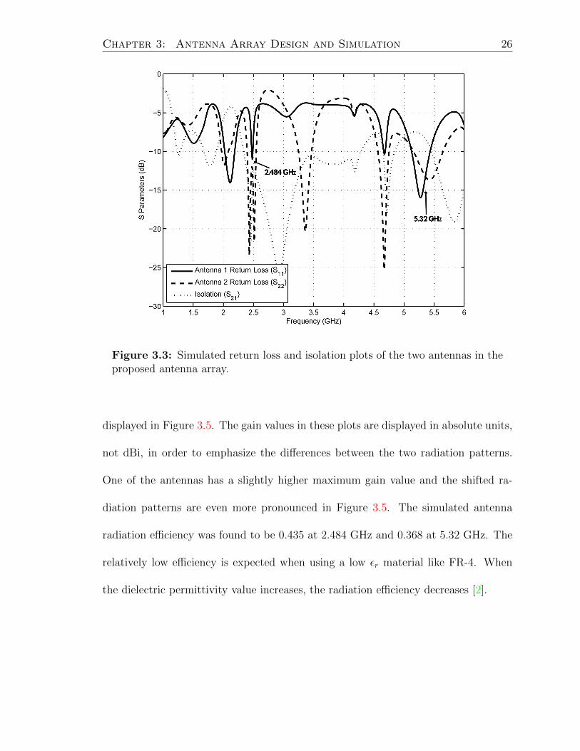
solver for electromagnetic structures. Figure 3.3 shows a plot of the simulated return
loss of the two antennas (S11 and S22). As can be seen from the figure, the antennas
have similar but not identical return loss curves. However, they both radiate in the

Chapter 3: Antenna Array Design and Simulation 24
(a) (b)
(c)
Figure 3.2: Schematics of the proposed antenna array design: (a) front view,(b) back view, and (c) perspective view.

Chapter 3: Antenna Array Design and Simulation 25
Table 3.1: Antenna array structural parameters.
AntennaOutside dipole arm length 14.75 mmInside dipole arm length 9.416 mmOutside dipole arm height 18 mmInside dipole arm height 6 mmDipole arm width 1.5 mmLeft antenna feedline thickness 3 mmRight antenna feedline thickness 1.5 mmFeedline length 48 mmBoard length 70 mmBoard width 75 mmBoard height 1.5748 mmSubstrateDielectric FR-4Dielectric permittivity 4.4Dielectric loss tangent 0.02Dielectric thickness 0.7874 mm
2.4 GHz and the 5 GHz bands as desired. The two antennas have return loss values
of -10.6 and -12.6 dB at 2.484 GHz, respectively, and -14.8 and -12.8 dB at 5.32 GHz,
respectively. The return loss is below the target -10 dB in the bands of interest for
both ports. The isolation between the two antenna ports (S21) is also shown on
Figure 3.3. The isolation is -14.0 dB at 2.484 GHz and -8.0 dB at 5.32 dB, below the
target -10 dB in the 2.4 GHz band but slightly above at the higher frequency.
Figure 3.4 shows the simulated azimuthal radiation patterns of each of the dipoles
in dBi. The radiation patterns are similar but shifted by approximately 45, demon-
strating the desired pattern diversity. The radiation patterns are likely not identical
because of the bridge used in the middle layer of the antenna, as it is the only
structural difference between the two antennas. Simulated 3D radiation patterns are
Chapter 3: Antenna Array Design and Simulation 26
Figure 3.3: Simulated return loss and isolation plots of the two antennas in theproposed antenna array.
displayed in Figure 3.5. The gain values in these plots are displayed in absolute units,
not dBi, in order to emphasize the differences between the two radiation patterns.
One of the antennas has a slightly higher maximum gain value and the shifted ra-
diation patterns are even more pronounced in Figure 3.5. The simulated antenna
radiation efficiency was found to be 0.435 at 2.484 GHz and 0.368 at 5.32 GHz. The
relatively low efficiency is expected when using a low εr material like FR-4. When
the dielectric permittivity value increases, the radiation efficiency decreases [2].

Chapter 3: Antenna Array Design and Simulation 27
0°
15°
30°
45°
60°
75°90°105°
120°
135°
150°
165°
±180°
−165°
−150°
−135°
−120°
−105°−90° −75°
−60°
−45°
−30°
−15°
−18−14−10−6−2
Figure 3.4: Simulated radiation patterns in dBi of the two antennas in theproposed antenna array at 2.484 GHz.
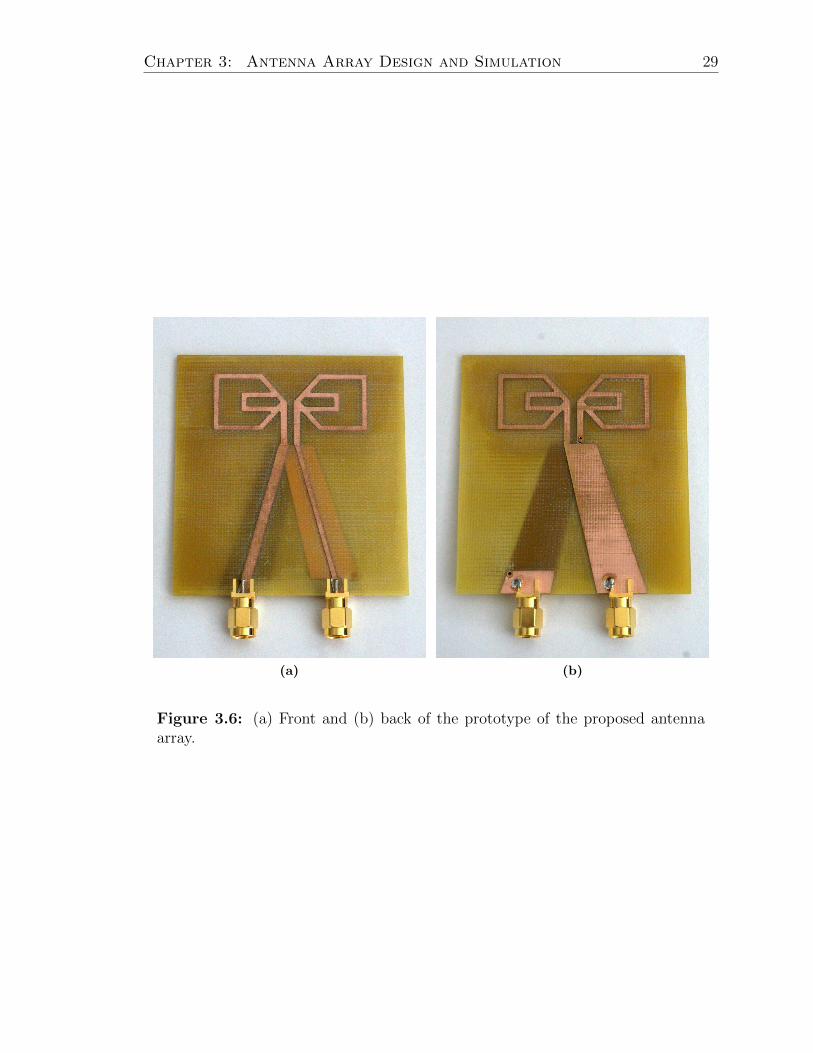
3.4 Antenna Array Construction
The proposed antenna array allows for a low-cost manufacturing solution. The anten-
nas were milled using a T-Tech Quick Circuit 5000S-FA milling machine [34] on FR-4
dielectric substrate of 31 mil thickness. After milling, the three layers were connected
using copper interconnects, and the layers were adhered together using a LPKF Mul-
tiPress S multiboard press [35]. The final prototype can be seen in Figure 3.6. The
bridge in the middle layer can be seen clearly through the back of the antenna array,
in Figure 3.6b.

Chapter 3: Antenna Array Design and Simulation 28
(a)
(b)
Figure 3.5: Simulated 3D radiation patterns of the two antennas in the proposedantenna array at 2.484 GHz.
Chapter 3: Antenna Array Design and Simulation 29
(a) (b)
Figure 3.6: (a) Front and (b) back of the prototype of the proposed antennaarray.

30
Chapter 4: Antenna Array Measurement Results
4.1 Measured Antenna Parameters
The scattering parameters of the dipoles were measured using an Agilent N5230A
Vector Network Analyzer (VNA). The decision was made to perform 5 GHz measure-
ments at 5.805 GHz instead of 5.32 GHz because i) the S-parameters at 5.805 GHz on
the manufactured antenna appear superior to those at 5.32 GHz and ii) the 5.805 GHz
frequency, corresponding to Channel 161, is also free from outside interference. Since
radiation at either frequency is sufficient for 5 GHz channel measurements, the an-
tenna did not have to be redesigned, but rather the target frequency in the 5 GHz
band could simply be changed since the intended design did not have a specific target
frequency in mind.
Figure 4.1 shows the measured return loss curves of the two antennas. The two
antennas have return loss values of -16.2 and -15.7 dB at 2.484 GHz, respectively,
and -16.9 and -17.3 dB at 5.805 GHz, respectively, both well below the target -10 dB
value. The return loss values are comparable to the results of the simulations. The
other peaks seen in Figure 4.1 are caused by coupling between the antennas. The
isolation between the two antennas is -12.8 dB at 2.484 GHz and -18.5 dB at 5.805 dB,
again both well below the target -10 dB and exceeding the simulated results.
Radiation patterns were measured in the Drexel anechoic chamber. Figure 4.2
shows the measured azimuthal radiation patterns in dBi taken at 2.484 and 5.805 GHz.

Chapter 4: Antenna Array Measurement Results 31
Figure 4.1: Measured return loss and isolation plots of the two antennas in theproposed antenna array.
The measured radiation patterns are similar to the simulated ones at 2.484 GHz, with
a comparable shift between the two patterns – approximately 45. The 5.805 GHz
radiation patterns do not look as similar to simulated results, but still exhibit some
pattern diversity. Unfortunately, accurate gain values were not able to be measured
in the 5 GHz band due to limitations of the anechoic chamber. The chamber is not
able to be calibrated for the higher frequency band.
4.2 Channel Measurements
The antenna array was tested as part of a system by taking channel measurements in
an indoor environment using the Wireless Open-Access Research Platform (WARP),

Chapter 4: Antenna Array Measurement Results 32
0°
15°
30°
45°
60°
75°90°105°
120°
135°
150°
165°
±180°
−165°
−150°
−135°
−120°
−105°−90° −75°
−60°
−45°
−30°
−15°
−16−12−8−40
(a)
0°
15°
30°
45°
60°
75°90°105°
120°
135°
150°
165°
±180°
−165°
−150°
−135°
−120°
−105°−90° −75°
−60°
−45°
−30°
−15°
−20−10
0
(b)
Figure 4.2: Measured radiation patterns in dBi of the two antennas in theproposed antenna array at (a) 2.484 GHz, and at (b) 5.805 GHz.

Chapter 4: Antenna Array Measurement Results 33
a software defined radio testbed developed by Rice University [36]. A 2 × 2 MIMO
orthogonal frequency division multiplexing (OFDM) implementation of WARP was
used. Measurements were performed on channel 14 of the 802.11 band (centered
at 2.484 GHz) and at channel 161 (centered at 5.805 GHz), each with a 20 MHz
bandwidth. The measurements were taken in Drexel’s Wireless Systems Laboratory
on the 3rd floor of the Bossone Research building in Drexel University. A floor plan of
the environment, along with the locations of the TX and RX can be seen in Figure 4.3.
The receiver remained stationary while a TDK PP-02 field probe positioner [37] was
used to sweep the transmitter along a 1.5 m × 1.5 m grid in the horizontal and vertical
directions in 50 cm steps. The channel matrix was measured for each location of the
transmitter for both frequencies. Due to the vertical displacement of the transmitter,
the measurements consisted of a combination of both line-of-sight (LOS) and non-
line-of-sight (NLOS) links.
The printed dipoles described in [38] were used as reference antennas for com-
parison of the proposed design. Since the antennas in [38] are only designed for
2.484 GHz, the design was scaled and analogous dipoles were manufactured for the
5 GHz band. One of the 2.4 GHz dipoles and one of the 5 GHz dipoles joined by
a splitter were used at each port of the 2 × 2 MIMO system and the measurements
were repeated as described above for the proposed antenna array. Because of uniform
power allocation, each of the reference dipoles received half of the total input power
[39]. This was done because each of the two antennas in the proposed antenna array
would be replacing two of the reference dipoles in a communication system.
WARP was used to measure the channel matrix at each location of the transmitter

Chapter 4: Antenna Array Measurement Results 34
Figure 4.3: Floor plan of test environment. Test locations of TX and RX areindicated.
for both frequencies and for different separation distances of the reference antennas.
The separation distances used were λ and λ/2 for the 2.4 GHz band and 2λ and λ for
the 5 GHz band. The λ/2 separation was impossible to achieve with the shortened
wavelength corresponding to the 5 GHz band because of the way the antennas were
mounted.
Figure 4.4 shows the proposed antenna array next to the reference dipoles. Ta-
ble 4.1 displays the area of each antenna array. The area of the proposed system is
reduced by approximately 58% with respect to a reference system composed of two
2.4 GHz dipoles and two 5 GHz dipoles separated by λ/2 in order to generate spatial
diversity in the system.

Chapter 4: Antenna Array Measurement Results 35
Figure 4.4: Comparison of the proposed antenna array (left) and the referencedipoles (right).
Table 4.1: Area of the proposed antenna array and reference antenna array.
Antenna Area (cm2)Reference dipole array 124.3Proposed antenna array 52.5
Channel capacity is selected as the performance metric because it allows the study
of the antenna array performance independently from the system modulation and the
adopted coding technique [2]. To determine the capacity of the MIMO OFDM link,
a Frobenius normalization of the channel matrix for each subcarrier was computed
in order to remove the differences in path loss among the different channel matrices
while preserving the relative antenna gain effects [6]. The normalization factor is

Chapter 4: Antenna Array Measurement Results 36
defined as [6]:
NF =
√‖Href‖2FNtNr
(4.1)
Since the channel was characterized over a broad frequency band, the capacity
of the wideband channel was defined as an average value of the capacities over all
the m subcarriers of the MIMO OFDM system [40]. The capacity was additionally
averaged over the k samples in order to minimize the impact arising from the minor
differences in spatial orientation between the stacked dipole array and the reference
dipoles.
Therefore, an estimator of the Shannon capacity is the average of the capacities
over the m subcarriers and the k samples, and was determined using [10]:
C =1
km
k∑j
m∑i
log2
[det
(INr +
SNR
Nt
HijH†ij
N2Fij
)](4.2)
where m is the total number of subcarriers, k is the total number of samples, and NFij
is the Frobenius norm for each subcarrier and sample. In this experiment, m = 52
subcarriers and k = 3200 samples (200 samples at each of the 16 locations) were used.
There are 64 total subcarriers, but only 52 are used for data transmission. A separate
Frobenius norm was calculated for each frequency band. The optimal solution for the
reconfigurable antenna was the one that guaranteed the highest average capacity.
4.2.1 Channel Measurement Results
Figure 4.5 shows the CDF plots of the capacity of the stacked antenna array and the
reference dipoles in the indoor environment shown in Figure 4.3 for both measured

Chapter 4: Antenna Array Measurement Results 37
frequencies assuming an SNR of 10 dB. The proposed antenna array significantly
increases MIMO link capacity with respect to a conventional dipole system. As can
be seen in Figure 4.5a, the proposed antenna array convincingly outperforms the
reference dipoles at both spacings in the 2.4 GHz band. It does not perform as well
in the 5 GHz band, but it is still comparable to the reference dipoles at the higher
frequency while providing a form factor improvement.
Table 4.2 shows the average percentage capacity improvement in the 2.4 GHz band
by using the stacked antenna array with respect to the reference dipoles for different
values of SNR in a MIMO OFDM system. Table 4.3 shows the same in the 5 GHz
band. At an SNR of 10 dB, the proposed antenna array outperforms the optimal
configuration of the reference dipoles by 22% in the 2.4 GHz band, and the capacity
improvement ranges from 33% at 5 dB SNR to 8% at 30 dB SNR. As can be seen, the
proposed antenna array performs better with respect to the reference antennas at low
SNR values. Figure 4.6 shows the capacity of the stacked antenna array measured at
2.484 GHz as a function of SNR.
The performance of the antenna in the 5 GHz band was roughly comparable to the
performance of the reference dipoles, at both separations and at all SNR values. The
median capacity improvement ranges from 3% at 5 dB SNR to -3% at 30 dB SNR.
The performance of the proposed antenna array is much worse in the 5 GHz frequency
band than in the 2.4 GHz band, but even at the higher frequency the performance
is still similar to the reference dipoles. Again, the proposed antenna array performs
better at low SNR values.
It is likely that the pattern diversity of the proposed antenna array was not as

Chapter 4: Antenna Array Measurement Results 38
1.5 2 2.5 3 3.5 4 4.5 5 5.5 6 6.50
0.1
0.2
0.3
0.4
0.5
0.6
0.7
0.8
0.9
1
Capacity (bps/Hz)
F(x
)
Stacked Antenna ArrayReference Array − λ/2 SeparationReference Array − λ Separation
(a)
0 1 2 3 4 5 60
0.1
0.2
0.3
0.4
0.5
0.6
0.7
0.8
0.9
1
Capacity (bps/Hz)
F(x
)
Stacked Antenna ArrayReference Array − λ SeparationReference Array − 2λ Separation
(b)
Figure 4.5: CDF of capacity of the stacked antenna array and the referencedipoles assuming 10 dB SNR, measured at (a) 2.484 GHz, and at (b) 5.805 GHz.

Chapter 4: Antenna Array Measurement Results 39
significant in the 5 GHz band, which contributed to the poor capacity measurement
results in that band. The radiation patterns in the 2.4 GHz band demonstrate pattern
diversity (Figure 4.2a) and therefore the system using the antenna array at that
frequency has good channel capacity results. However, since the radiation patterns
in the 5 GHz band are not as clean and the gain values are unknown (Figure 4.2b),
the channel capacity suffered.
Table 4.2: Average measured percentage capacity improvement achievable withthe stacked antenna array at 2.484 GHz with respect to the λ and λ/2 separationsof the reference dipoles.
SNR (dB) 5 10 20 30Capacity improvement w.r.t. λ/2 separation 33% 22% 13% 8%Capacity improvement w.r.t. λ separation 39% 31% 19% 12%
Table 4.3: Average measured percentage capacity improvement achievable withthe stacked antenna array at 5.805 GHz with respect to the 2λ and λ separationsof the reference dipoles.
SNR (dB) 5 10 20 30Capacity improvement w.r.t. λ separation 3% -1% -2% -3%Capacity improvement w.r.t. 2λ separation 2% -2% -3% -3%

Chapter 4: Antenna Array Measurement Results 40
0 2 4 6 8 10 12 14 16 18 200
0.1
0.2
0.3
0.4
0.5
0.6
0.7
0.8
0.9
1
Capacity (bps/Hz)
F(x
)
30 dB SNR20 dB SNR10 dB SNR5 dB SNR
Figure 4.6: CDF of capacity of the stacked antenna array as a function of SNRat 2.484 GHz.
41
Chapter 5: Discussion and Future Research
5.1 Discussion
A compact stacked multiband dipole antenna array for MIMO communication systems
is proposed in this thesis. The two dipoles in the antenna array each demonstrate fre-
quency diversity individually while also demonstrating pattern diversity with respect
to one another. The antenna array is compact and eliminates the antenna spacing
typically required in MIMO antenna arrays for spatial diversity. The proposed an-
tenna array has been shown to provide an improvement in capacity when compared
against traditional dipoles. An additional benefit of the proposed design is that by
combining two antenna elements in this fashion, manufacturing costs and valuable
space in mounting the antenna are saved.
All of the antennas described in Section 1.2 exhibit at least one form of diversity.
However, most of these antennas have some drawbacks as well. The antennas in [6–10,
15] all operate in a single frequency band, making them impractical for applications
such as WiFi that use both the 2.4 and the 5 GHz bands. The pixel antenna presented
in [13] can tune both its frequency and its radiation pattern by exciting different
modes of radiation. However, by utilizing hundreds of MEMS switches, the authors
introduce losses into the system. The losses are much smaller than if they had used
diodes, but they still contribute to decreases in the antenna’s radiation efficiency.
Additionally, as the authors themselves state, MEMS are not currently reliable enough

Chapter 5: Discussion and Future Research 42
on PCB to introduce the antenna into industry [13].
The linear array of two printed dipoles fed through a microstrip balun in [14]
is the most similar to the antenna array proposed in this thesis. The dipoles are
already dual band, resonating at 2.3 and 5.2 GHz, and are oriented in a fashion that
introduces pattern diversity through mutual coupling. The authors orient one of the
dipoles upside down and alongside the other one. Due to this antenna positioning,
however, the antenna array becomes rather bulky.
On the other hand, the stacked dipole array proposed in this thesis efficiently
utilizes its board space while exhibiting pattern and frequency diversity, making it
more suited for space constrained wireless devices.
5.2 Future Research
Future research will focus on the improvement of the 5 GHz band of the dipoles
in the proposed array. Currently, the measured radiation patterns in the 5 GHz
band do not match the simulated radiation patterns nearly as well as those in the
2.4 GHz band. As a result, measurements taken in the 5 GHz band have significantly
lower capacities than those taken in the 2.4 GHz band. If the isolation, and thus
the efficiency, of the antennas at higher frequencies is improved, perhaps with better
matching or a matching network, the capacity measurements should improve as well.
It is also worthwhile to consider taking measurements at a different frequency in the
5 GHz band to see if that can improve the capacity.
The efficiency of the antenna array can also be improved by using a material with
a higher dielectric permittivity constant as the antenna substrate instead of FR-4,

Chapter 5: Discussion and Future Research 43
which has an εr of 4.4. For example, Rogers RO3010 material has an εr of 10.2
and would be a good initial candidate to replace FR-4. However, depending on the
material chosen, it is likely that it would no longer be possible to manufacture the
antenna array in-house as many of the higher εr materials are too brittle to be milled.
The antenna structure is designed in such a way that it would also be very easy
to add more frequency bands by nesting extra printed dipoles inside the existing
ones. Therefore, in the future it would be possible to have the antennas in the array
resonate at additional frequencies if their application required them to do so.

44
Appendix A: Table of Symbols
Symbol DescriptionCn×m operator to denote complex matrix with dimension n×mdet(·) determinant operator· inner product operator| · | absolute value operator‖ · ‖F Frobenius norm operator(·)† complex conjugate transpose operatorC channel capacityd separation of the TX and RXH channel matrixHw matrix of complex Gaussian coefficientsh scalar channelIn identity matrix with dimension n× nk total number of samplesL path lossm total number of subcarriersN minimum number of antenna elements between the TX and RXNF Frobenius normalization factorNr number of receive antenna elementsNt number of transmit antenna elementsn complex additive white Gaussian noisen complex additive white Gaussian noise vectorPt transmitted powerRr receive spatial correlation matrixRt transmit spatial correlation matrixS11 voltage reflection coefficientS21 voltage forward transmission coefficientSNR signal to noise ratiox signal at the transmitterx signal vector at the transmittery signal at the receivery signal vector at the receiverεr dielectric permittivityλ wavelengthσ2n variance of the additive white Gaussian noise

45
Appendix B: Table of Acronyms
Acronym DefinitionAWGN Additive White Gaussian NoiseCDF Cumulative Distribution FunctionEM ElectromagneticHFSS High Frequency Structural SimulatorLOS Line-of-SightMEMS Microelectromechanical SystemsMIMO Multiple Input Multiple OutputNLOS Non-Line-of-SightOFDM Orthogonal Frequency Division MultiplexingPCB Printed Circuit BoardRF Radio FrequencyRX ReceiverSISO Single Input Single OutputSNR Signal to Noise RatioTX TransmitterVNA Vector Network AnalyzerWARP Wireless Open-Access Research PlatformWLAN Wireless Local Area Network

46
Bibliography
[1] C. Lee, A. Gummalla, and M. Achour, “Compact dualband antenna subsystemfor MIMO application,” in IEEE International Workshop on Antenna Technol-ogy, pp. 1–4, 2009.
[2] D. Piazza, Reconfigurable antennas for adaptive MIMO communication systems.PhD thesis, Drexel University, 2009.
[3] M. Cortes, Study of performance of reference MIMO antenna configurations usingexperimental propagation data. PhD thesis, Helsinki University of Technology,2009.
[4] Z. H. Hu, P. S. Hall, and P. Gardner, “Reconfigurable dipole-chassis antennas forsmall terminal MIMO applications,” Electronics Letters, vol. 47, no. 17, pp. 953–955, 2011.
[5] Z. Li, Z. Du, and K. Gong, “Compact reconfigurable antenna array for adap-tive MIMO systems,” IEEE Antennas and Wireless Propagation Letters, vol. 8,pp. 1317–1320, 2009.
[6] D. Piazza, N. J. Kirsch, A. Forenza, R. W. Heath, and K. R. Dandekar, “Designand evaluation of a reconfigurable antenna array for MIMO systems,” IEEETransactions on Antennas and Propagation, vol. 56, no. 3, pp. 869–881, 2008.
[7] P. Mookiah, D. Piazza, and K. R. Dandekar, “Reconfigurable spiral antennaarray for pattern diversity in wideband MIMO communication systems,” in An-tennas and Propagation Society International Symposium, pp. 1–4, 2008.
[8] D. Piazza, P. Mookiah, M. D’Amico, and K. R. Dandekar, “Two port reconfig-urable circular patch antenna for MIMO systems,” in European Conference onAntennas and Propagation, pp. 1–7, 2007.
[9] D. Piazza, M. Capacchione, J. Kountouriotis, M. D’Amico, and K. R. Dan-dekar, “Stacked reconfigurable circular patch antenna for adaptive MIMO sys-tems,” in International Conference on Electromagnetics in Advanced Applica-tions, pp. 636–639, Sept. 2009.
[10] P. Qin, Y. J. Guo, and A. R. Weily, “A pattern reconfigurable U-slot antennaand its applications in MIMO systems,” IEEE Transactions on Antennas andPropagation, vol. 60, no. 2, pp. 516–528, 2012.

Bibliography 47
[11] J. Kountouriotis, D. Piazza, K. R. Dandekar, M. D’Amico, and C. Guardiani,“Performance analysis of a reconfigurable antenna system for MIMO communi-cations,” in European Conference on Antennas and Propagation, pp. 543–547,2011.
[12] A. Lackpour, P. Mookiah, M. Olivieri, and K. R. Dandekar, “Evaluation ofthe reconfigurable printed fractal tree antenna for enhanced pattern diversity inMIMO systems,” in IEEE Radio and Wireless Symposium, pp. 96–99, 2010.
[13] A. Grau, J. Romeu, L. Jofre, and F. De Flaviis, “A software defined MEMS-reconfigurable PIXEL-Antenna for narrowband MIMO systems,” in NASA/ESAConference on Adaptive Hardware and Systems, pp. 141–146, June 2008.
[14] E. Michailidis, C. Tsimenidis, and G. Chester, “Printed dipole array for MIMOwireless networks,” in Loughborough Antennas and Propagation Conference,no. April, pp. 117–120, 2007.
[15] Y. Im, J. Lee, R. A. Bhatti, and S. Park, “A spiral-dipole antenna for MIMOsystems,” IEEE Antennas and Wireless Propagation Letters, vol. 7, pp. 803–806,2008.
[16] J. Sarrazin, Y. Mahe, S. Avrillon, and S. Toutain, “On the bandwidth enhance-ment of a multipolarization and reconfigurable pattern antenna for adaptiveMIMO systems,” in Antennas and Propagation Society International Sympo-sium, pp. 485–488, 2007.
[17] A. F. Molisch, Wireless Communications. Wiley, 2005.
[18] M. Jankiraman, Space Time Codes and MIMO Systems. Artech House, 2004.
[19] J. P. Kermoal, L. Schumacher, K. I. Pedersen, P. E. Mogensen, and F. Frederik-sen, “A stochastic MIMO radio channel model with experimental validation,”IEEE Journal on Selected Areas in Communications, vol. 20, no. 6, pp. 1211–1226, 2002.
[20] K. Chang, RF and Microwave Wireless Systems. Wiley, 2000.
[21] H. Liu and H. Lee, “A high performance four-parallel 128/64-point radix-2ˆ4FFT/IFFT processor for MIMO-OFDM systems,” in IEEE Asia Pacific Con-ference on Circuits and Systems, pp. 834–837, 2008.
[22] P. M. Shankar, Introduction to Wireless Systems. Wiley, 2002.
[23] C. Chiau, Study of the diversity antenna array for the MIMO wireless commu-nication systems. PhD thesis, University of London, 2006.
[24] J. D. Boerman and J. T. Bernhard, “Performance study of pattern reconfigurableantennas in MIMO communication systems,” IEEE Transactions on Antennasand Propagation, vol. 56, no. 1, pp. 231–236, 2008.

Bibliography 48
[25] M. El-Hajjar and L. Hanzo, “Multifunctional MIMO systems: A combined di-versity and multiplexing design perspective,” IEEE Wireless Communications,vol. 17, no. 2, pp. 73–79, 2010.
[26] K. R. Dandekar, S. Kawale, L. Dong, and R. W. Heath, “Electromagnetic char-acterization of MIMO communication systems.” 2002.
[27] A. Grau, J. Romeu, M. Lee, S. Blanch, L. Jofre, and F. De Flaviis, “A dual-linearly-polarized MEMS-reconfigurable antenna for narrowband MIMO com-munication systems,” IEEE Transactions on Antennas and Propagation, vol. 58,no. 1, pp. 4–17, 2010.
[28] C. A. Balanis, Antenna Theory. Wiley, 1997.
[29] P. Mookiah, Reconfigurable antennas for wireless network security. PhD thesis,Drexel University, 2011.
[30] S. Yang, C. Zhang, H. K. Pan, A. E. Fathy, and V. K. Nair, “Frequency-reconfigurable antennas for multiradio wireless platforms,” IEEE MicrowaveMagazine, vol. 10, no. 1, pp. 66–83, 2009.
[31] K. R. Dandekar and R. W. Heath, “Modelling realistic electromagnetic effectson MIMO system capacity,” Electronics Letters, vol. 38, no. 25, pp. 1624–1625,2002.
[32] P. Wu, Z. Kuai, and X. Zhu, “Multiband antennas comprising multiple frame-printed dipoles,” IEEE Transactions on Antennas and Propagation, vol. 57,no. 10, pp. 3313–3316, 2009.
[33] “ANSYS HFSS.” [Online]. Available: http://www.ansys.com/Products/Simulation+Technology/Electromagnetics/High-Performance+Electronic+Design/ANSYS+HFSS.
[34] “T-Tech, Quick Circuit Prototyping Systems.” [Online]. Available: http://t-techtools.com/store/.
[35] “LPKF MultiPress S.” [Online]. Available: http://www.lpkfusa.com/rapidpcb/throughholeplating/multipress s.htm.
[36] “Rice University WARP.” [Online]. Available: http://warp.rice.edu.
[37] “TDK RF Solutions – Field Probe Positioner (PP-02).” [Online]. Available:http://tdkrfsolutions.com/WebDataSheets/PP-02WebSheet.htm.
[38] H. Chuang and L. Kuo, “3-D FDTD design analysis of a 2.4-GHz polarization-diversity printed dipole antenna with integrated balun and polarization-switchingcircuit for WLAN and wireless communication applications,” IEEE Transactionson Microwave Theory and Techniques, vol. 51, no. 2, pp. 374–381, 2003.

Bibliography 49
[39] Q. Chu and R. Dong, “A novel multi-channel spatial power splitter,” in Inter-national Conference on Microwave and Millimeter Wave Technology, pp. 1–3,2007.
[40] H. Bolcskei, D. Gesbert, and A. J. Paulraj, “On the capacity of OFDM-basedspatial multiplexing systems,” IEEE Transactions on Communications, vol. 50,no. 2, pp. 225–234, 2002.
