a theory of shape by space carving - loria · a theory of shape by space carving kiriakos n....
TRANSCRIPT

A Theory of Shape by Space Carving
Kiriakos N. [email protected]
Steven M. [email protected]
University of Rochester CS Technical Report #692May 1998
Abstract
In this paper we consider the problem of computing the 3D shape of an unknown, arbitrarily-shaped scenefrom multiple color photographs taken at known but arbitrarily-distributed viewpoints. By studying the equiv-alence class of all 3D shapes that reproduce the input photographs, we prove the existence of a special memberof this class, the maximal photo-consistent shape, that (1) can be computed from an arbitrary volume that con-tains the scene, and (2) subsumes all other members of this class. We then give a provably-correct algorithm,called Space Carving, for computing this shape and present experimental results from applying it to the recon-struction of geometrically-complex scenes from several photographs. The approach is specifically designedto (1) build 3D shapes that allow faithful reproduction of all input photographs, (2) resolve the complex in-teractions between occlusion, parallax, shading, and their effects on arbitrary collections of photographs of ascene, and (3) follow a “least commitment” approach to 3D shape recovery.
1

1 Introduction
A fundamental problem in computer vision is reconstructing the shape of a complex 3D scene from multiple
photographs. While current techniques work well under controlled conditions (e.g., small stereo baselines [1],
active viewpoint control [2], spatial and temporal smoothness [3–5], or scenes containing curved lines [6], planes
[7], or texture-less surfaces [8–12]), very little is known about scene reconstruction under general conditions. In
particular, in the absence of a priori geometric information, what can we infer about the structure of an unknown
scene from�
arbitrarily positioned cameras at known viewpoints? Answering this question has especially im-
portant implications for reconstructing real objects and environments, which often tend to be non-smooth, exhibit
significant occlusions, and may contain both strongly-textured as well as texture-less surface regions (Fig. 1).
In this paper, we develop a theory for reconstructing arbitrarily-shaped scenes from arbitrarily-positioned
cameras by formulating shape recovery as a constraint satisfaction problem. We show that any set of photographs
of a rigid scene defines a collection of picture constraints that are satisfied by every scene projecting to those
photographs. Furthermore, we show how to characterize the set of all 3D shapes that satisfy these constraints
and use the underlying theory to design a practical reconstruction algorithm, called Space Carving, that applies
to fully-general shapes and camera configurations. In particular, we address three questions:
� Given�
input photographs, can we characterize the set of all photo-consistent shapes, i.e., shapes that
reproduce the input photographs when assigned appropriate reflectance properties and are re-projected to
the input camera positions?
� Is it possible to compute a shape from this set and if so, what is the algorithm?
� What is the relationship of the computed shape to all other photo-consistent shapes?
Our goal is to study the�
-view shape recovery problem in the general case where no a priori assumptions
are made about the scene’s shape or about the input photographs. In particular, we address the above questions
for the case when (1) no a priori constraints are imposed on scene geometry or topology, (2) no constraints are
imposed on the positions of the input cameras, (3) no information is available about the existence of specific
image features in the input photographs (e.g., edges, points, lines, contours, texture, or color), and (4) no a priori
correspondence information is available. Unfortunately, even though several algorithms have been proposed for
recovering shape from multiple views that work under some of these conditions (e.g., work on stereo [13–15]),
very little is currently known about how to answer the above questions, and even less so about how to answer
them in this general case.
1

(a) (b)
Fig. 1: The scene volume and camera distribution covered by our analysis can both be completely arbitrary.
Examples include (a) a 3D environment viewed from a collection of cameras that are arbitrarily dispersed in free
space, and (b) a 3D object viewed by a single camera moving around it.
At the heart of our work is the observation that these questions become tractable when scene radiance be-
longs to a general class of radiance functions we call locally computable. This class characterizes scenes for which
global illumination effects such as shadows, transparencies and inter-reflections can be ignored, and is sufficiently
general to include scenes with parameterized radiance models (e.g., Lambertian, Phong [16], Torrance-Sparrow
[17]). Using this observation as a starting point, we show how to compute, from�
arbitrary photographs of an
unknown scene, a maximal photo-consistent shape that encloses the set of all photo-consistent reconstructions.
The only requirements are that (1) the viewpoint of each photograph is known in a common 3D world reference
frame (Euclidean, affine [18], or projective [19]), and (2) scene radiance follows a known, locally-computable ra-
diance function. Experimental results illustrating our method’s performance are given for both real and simulated
geometrically-complex scenes.
Central to our analysis is the realization that parallax, occlusion, and scene radiance all contribute to a photo-
graph’s ultimate dependence on viewpoint. Since our notion of photo-consistency implicitly ensures that all these
3D shape cues are taken into account in the recovery process, our approach is related to work on stereo [1, 14, 20],
shape-from-contour [8, 9, 21], as well as shape-from-shading [22–24]. These approaches rely on studying a single
3D shape cue under the assumptions that (1) other sources of variability can be safely ignored, and (2) the input
2

photographs contain features relevant to that cue [25].1 Unfortunately, these approaches cannot be easily general-
ized to attack the�
-view reconstruction problem for arbitrary 3D scenes because neither assumption holds true
in general. Implicit in this previous work is the view that untangling parallax, self-occlusion and shading effects
in�
arbitrary photographs of a scene leads to a problem that is either under-constrained or intractable. Here we
challenge this view by showing that shape recovery from�
arbitrary photographs of an unknown scene is not
only a tractable problem but has a simple solution as well.
To our knowledge, no previous theoretical work has studied the equivalence class of solutions to the general�
-view reconstruction problem, the ambiguities it embodies, or provably-correct algorithms for computing it.
The Space Carving Algorithm that results from our analysis, however, does operate in a 3D scene space and
is therefore related to other scene-space stereo algorithms that have been recently proposed [27–34]. Of these,
most closely related are recent mesh-based [27] and level-set [35] algorithms, as well as algorithms that sweep a
plane or other manifold through a discretized scene space [28–30, 33]. While the algorithms in [27, 35] generate
high-quality reconstructions and perform well in the presence of occlusions, their use of regularization techniques
penalizes complex surfaces and shapes. Even more importantly, no formal study has been undertaken to establish
their validity for recovering arbitrarily-shaped scenes and for the case where images are taken under fully-general
camera configurations (e.g., the one shown in Fig. 1(a)). In contrast, our Space Carving Algorithm is provably
correct and has no regularization biases. Even though space-sweep approaches have many attractive properties,
existing algorithms [28–30, 33] are not general i.e., they rely on the presence of specific image features such as
edges and hence generate only sparse reconstructions [28], or they place strong constraints on the input viewpoints
relative to the scene [29, 30]. Our implementation of the Space Carving Algorithm also uses plane sweeps, but
unlike all previous methods the algorithm guarantees complete reconstructions in the general case.
Our approach offers six main contributions over the existing state of the art:
1. It introduces an algorithm-independent analysis of the shape recovery problem from�
arbitrary pho-
tographs, making explicit the assumptions about scene radiance and free space required for solving it as
well as the ambiguities intrinsic to the problem. This analysis not only extends previous work on re-
construction but also puts forth a concise geometrical framework for analyzing the general properties of
recently-proposed scene-space stereo techniques [27–34]. In this respect, our analysis has goals simi-
lar to those of theoretical approaches to structure-from-motion [36], although the different assumptions
employed (i.e., unknown vs. known correspondences, known vs. unknown camera motion), make the
1Examples include the use of the small baseline assumption in stereo to simplify correspondence-finding and maximize joint visibilityof scene points [26], the availability of easily-detectable image contours in shape-from-contour reconstruction [9], and the assumptionthat all views are taken from the same viewpoint in photometric stereo [24].
3

geometry, solution space, and underlying techniques completely different.
2. Our analysis provides a volume which is the tightest possible bound on the shape of the true scene that
can be inferred from�
photographs. This bound is important because it tells us precisely what shape
information we can hope to extract from�
photographs, in the absence of a priori geometric and point
correspondence information, regardless of the specific algorithm being employed.
3. The Space Carving Algorithm presented in this paper is the only provably-correct method, to our knowl-
edge, that enables scene reconstruction from input cameras at arbitrary positions. As such, the algo-
rithm enables reconstruction of complex scenes from viewpoints distributed throughout an unknown 3D
environment—an extreme example is shown in Fig. 10 where the interior and exterior of a house are re-
constructed simultaneously from cameras distributed throughout the inside and outside of the house.
4. Because no constraints on the camera viewpoints are imposed, our approach leads naturally to global
reconstruction algorithms [12, 37] that recover 3D shape information from all photographs in a single
step. This eliminates the need for complex partial reconstruction and merging operations [38, 39] in which
partial 3D shape information is extracted from subsets of the photographs [32, 40–42], and where global
consistency with the entire set of photographs is not guaranteed for the final shape.
5. We describe a simple multi-sweep implementation of the Space Carving Algorithm that enables recovery
of photo-realistic 3D models from multiple photographs of real scenes.
6. Because the shape recovered via Space Carving is guaranteed to be photo-consistent, its reprojections
will closely resemble photographs of the true scene. This property is especially significant in computer
graphics, virtual reality, and tele-presence applications [40, 43–47] where the photo-realism of constructed
3D models is of primary importance.
1.1 Least-Commitment Shape Recovery
A key consequence of our photo-consistency analysis is that no finite set of input photographs of a 3D scene
can uniquely determine the scene’s 3D shape: in general, there exists an uncountably-infinite equivalence class
of shapes each of which reproduces all the input photographs exactly. This result is yet another manifestation
of the well-known fact that 3D shape recovery from a set of images is generally ill-posed [3], i.e., there may be
multiple shapes that are consistent with the same set of images.2 Reconstruction methods must therefore choose2Faugeras [48] has recently proposed the term metameric to describe such shapes, in analogy with the term’s use in the color perception
[49] and structure-from-motion literature [50].
4

a particular scene to reconstruct from the space of all consistent shapes. Traditionally, the most common way
of dealing with this ambiguity has been to apply smoothness heuristics and regularization techniques [3, 51] to
obtain reconstructions that are as smooth as possible. A drawback of this type of approach is that it typically
penalizes discontinuities and sharp edges, features that are very common in real scenes.
The notion of the maximal photo-consistent shape introduced in this paper and the Space Carving Algorithm
that computes it lead to an alternative, least commitment principle [52] in choosing among all the photo-consistent
shapes: rather than making an arbitrary choice, we choose the only photo-consistent reconstruction that is guar-
anteed to subsume (i.e., contain within its volume) all other photo-consistent reconstructions of the scene. By
doing so we not only avoid the need to impose ad hoc smoothness constraints, which lead to reconstructions
whose relationship to the true shape are difficult to quantify, we also ensure that the recovered 3D shape can serve
as a description for the entire equivalence class of photo-consistent shapes.
While our work shows how to obtain a consistent scene reconstruction without imposing smoothness con-
straints or other geometric heuristics, there are many cases where it may be advantageous to impose a priori
constraints, especially when the scene is known to have a certain structure [53, 54]. Least-commitment recon-
struction suggests a new way of incorporating such constraints: rather than imposing them as early as possible in
the reconstruction process, we can impose them after first recovering the maximal photo-consistent shape. This
allows us to delay the application of a priori constraints until a later stage in the reconstruction process, when tight
bounds on scene structure are available and where these constraints are used only to choose among shapes within
the class of photo-consistent reconstructions. This approach is similar in spirit to “stratification” approaches of
shape recovery [18, 55], where 3D shape is first recovered modulo an equivalence class of reconstructions and is
then refined within that class at subsequent stages of processing.
The remainder of this paper is structured as follows. Section 2 analyzes the constraints that a set of pho-
tographs place on scene structure given a known, locally-computable model of scene radiance. Using these
constraints, a theory of photo-consistency is developed that provides a basis for characterizing the space of all
reconstructions of a scene. Sections 3 and 4 then use this theory to present the two central results of the paper,
namely the existence of the maximal photo-consistent shape and the development of a provably-correct algorithm
called Space Carving that computes it. Section 4.1 then presents a discrete implementation of the Space Carving
Algorithm that iteratively “carves” out the scene from an initial set of voxels. This implementation can be seen as
a generalization of silhouette-based techniques like volume intersection [21, 44, 56, 57] to the case of gray-scale
and full-color images, and extends voxel coloring [29] and plenoptic decomposition [30] to the case of arbitrary
5

Fig. 2: Viewing geometry.
camera geometries.3 Section 5 concludes with experimental results on real and synthetic images.
2 Picture Constraints
Let�
be a 3D scene defined by a finite, opaque, and possibly disconnected volume in space. We assume that�
is viewed under perspective projection from�
known positions ���������������� in ��� �(Fig. 2). The radiance
of a point � on the scene’s surface is a function rad ������� that maps every oriented ray � through the point to the
color of light reflected from � along � . We use the term shape-radiance scene description to denote the scene�
together with an assignment of a radiance function to every point on its surface. This description contains
all the information needed to reproduce a photograph of the scene for any camera position. In general, such a
photograph will contain a potentially empty set of background pixels that are not images of any scene point.
Every photograph of a 3D scene taken from a known location partitions the set of all possible shape-radiance
scene descriptions into two families, those that reproduce the photograph and those that do not. We characterize
this constraint for a given shape and a given radiance assignment by the notion of photo-consistency:4
Definition 1 (Point Photo-Consistency) A point � in�
that is visible from � is photo-consistent with the photo-
graph at � if (1) � does not project to a background pixel, and (2) the color at � ’s projection is equal to rad � �������� .
Definition 2 (Shape-Radiance Photo-Consistency) A shape-radiance scene description is photo-consistent with
3Note that both of these generalizations represent significant improvements in the state of the art. For instance, silhouette-basedalgorithms require identification of silhouettes, fail at surface concavities, and treat only the case of binary images. While [29, 30] alsoused a volumetric algorithm, their method worked only when the scene was outside the convex hull of the cameras. This restrictionstrongly limits the kinds of environments that can be reconstructed, as discussed in Section 5.
4In the following, we make the simplifying assumption that pixel values in the image measure scene radiance directly.
6

the photograph at � if all points visible from � are photo-consistent and every non-background pixel is the projec-
tion of a point in�
.
Definition 3 (Shape Photo-Consistency) A shape�
is photo-consistent with a set of photographs if there is an
assignment of radiance functions to the visible points of�
that makes the resulting shape-radiance description
photo-consistent with all photographs.
Our goal is to provide a concrete characterization of the family of all scenes that are photo-consistent with�
input photographs. We achieve this by making explicit the two ways in which photo-consistency with�
photographs can constrain a scene’s shape.
2.1 Background Constraints
Photo-consistency requires that no point of�
projects to a background pixel. If a photograph taken at position
� contains identifiable background pixels, this constraint restricts�
to a cone defined by � and the photograph’s
non-background pixels. Given�
such photographs, the scene is restricted to the visual hull, which is the volume
of intersection of their corresponding cones [10].
When no a priori information is available about the scene’s radiance, the visual hull defines all the shape
constraints in the input photographs. This is because there is always an assignment of radiance functions to the
points on the surface of the visual hull that makes the resulting shape-radiance description photo-consistent with
the�
input photographs.5 The visual hull can therefore be thought of as a “least commitment reconstruction” of
the 3D scene—any further refinement of this volume must necessarily rely on additional assumptions about the
scene’s shape or radiance.
While visual hull reconstruction has often been used as a method for recovering 3D shape from photographs
[21, 57, 58], the picture constraints captured by the visual hull only exploit information from the background
pixels in these photographs. Unfortunately, these constraints become useless when photographs contain no back-
ground pixels (i.e., the visual hull degenerates to � ) or when background identification [59] cannot be performed
accurately. Below we study the picture constraints provided by non-background pixels when the scene’s radiance
is restricted to a special class of radiance models. The resulting picture constraints will in general lead to photo-
consistent scenes that are strict subsets of the visual hull.5For example, set rad �
�������� equal to the color at � ’s projection.
7

2.2 Radiance Constraints
The color of light reflected in different directions from a single scene point usually exhibits a certain degree of
coherence for physical scenes that are not transparent or mirror-like. This coherence provides additional picture
constraints that depend entirely on non-background pixels. Here we exploit this idea by focusing on scenes whose
radiance satisfies the following criterion:
Consistency Check Criterion: An algorithm consist � � � is available that takes as input at least��� �
colors ����� � ������� ������� � ,�
vectors ��� ������� � � � , and the light source positions (non-Lambertian
case), and decides whether it is possible for a single surface point to reflect light of color ������ in
direction �� simultaneously for all � ��� ������� � � .
Given a shape�
, the Consistency Check Criterion gives us a way to establish the photo-consistency of every
point on�
’s surface. This criterion defines a general class of radiance models, which we call locally computable,
that are characterized by a locality property: the radiance at any point is independent of the radiance of all other
points in the scene. The class of locally-computable radiance models therefore restricts our analysis to scenes
where global illumination effects such as transparency, inter-reflection, and shadows can be ignored. This class
subsumes Lambertian radiance (� ��� ) as well as radiance models that can be expressed in closed form by a
small number of parameters.6
When an a priori locally computable radiance model is established for a physical 3D scene, the model pro-
vides sufficient information to determine whether or not a given shape�
is photo-consistent with a collection of
photographs. The use of radiance models that are locally consistent is important in this context because the non-
photo-consistency of a shape�
tells us a great deal about the shape of the underlying scene. This in turn imposes
a very special structure on the family of photo-consistent shapes. We use the following two lemmas to make this
structure explicit. These lemmas provide the analytical tools needed to describe how the non-photo-consistency
of a shape�
affects the photo-consistency of its subsets (Fig. 3):
Lemma 1 (Visibility Lemma) Let � be a point on�
’s surface, Surf � � � , and let Vis � � � � be the collection of
input photographs in which�
does not occlude � . If����� �
is a shape that also has � on its surface, Vis � � � ���Vis ��� � � � .
Proof: Since���
is a subset of�
, no point of���
can lie between � and the cameras corresponding to Vis � � � � . QED
6Specific examples include (1) using a mobile camera mounted with a light source to capture photographs of a scene whose reflectancecan be expressed in closed form (e.g., using the Torrance-Sparrow model [17, 47]), and (2) using multiple cameras to capture photographsof an approximately Lambertian scene under arbitrary unknown illumination (Fig. 1).
8

(a) (b)
Fig. 3: (a) Illustration of the Visibility Lemma. (b) Illustration of the Non-Photo-Consistency Lemma. If �is non-photo-consistent with the photographs at � ����� � ��� � , it is non-photo-consistent with the entire set Vis � � � � ,which also includes ��� .
Lemma 2 (Non-Photo-Consistency Lemma) If ��� Surf � � � is not photo-consistent with a subset of Vis � � � � , it
is not photo-consistent with Vis � � � � .
Intuitively, Lemmas 1 and 2 suggest that both visibility and non-photo-consistency exhibit a certain form
of “monotonicity:” the Visibility Lemma tells us that the collection of photographs from which a surface point
is visible strictly expands for nested subsets of�
that contain the point (Fig. 3(a)). Analogously, the Non-
Photo-Consistency Lemma, which follows as a direct consequence of the definition of photo-consistency, tells
us that each new photograph can be thought of as an additional constraint on the photo-consistency of surface
points—the more photographs are available, the more difficult it is for those points to maintain photo-consistency.
Furthermore, once a surface point becomes not photo-consistent no new photograph of the scene can re-establish
photo-consistency for that point.
The key consequence of Lemmas 1 and 2 is given by the following theorem which shows that non-photo-
consistency at a point rules out the photo-consistency of an entire family of shapes:
Theorem 1 (Subset Theorem) If ��� Surf � � � is not photo-consistent, no photo-consistent subset of�
contains
� .
Proof: Let� � � �
be a shape that contains � . Since � lies on the surface of�
, it must also lie on the surface
of� �
. From the Visibility Lemma it follows that Vis � � � � � Vis ��� � � � . The theorem now follows by applying
9

the Non-Photo-Consistency Lemma to���
and using the locality property of locally computable radiance models.
QED
We explore the ramifications of the Subset Theorem in the next section where we provide an explicit charac-
terization of the shape ambiguities inherent in the input photographs.
3 The Maximal Photo-Consistent Shape
The family of all shapes that are photo-consistent with a collection of�
photographs defines the ambiguity
inherent in the problem of recovering 3D shape from those photographs. This is because it is impossible to
decide, based on those photographs alone, which photo-consistent shape is the shape of the true scene. When
using photographs to recover the shape of a 3D scene, this ambiguity raises two questions:
� Is it possible to compute a shape that is photo-consistent with�
photographs and, if so, what is the
algorithm?
� If a photo-consistent shape can be computed, how can we relate that shape to all other photo-consistent 3D
interpretations of the scene?
Before providing a general answer to these questions we observe that when the number of input photographs
is finite, the first question can be answered with a trivial shape (Fig. 4). In general, trivial shape solutions such
as this one can only be eliminated with the incorporation of free space constraints, i.e., regions of space that are
known not to contain scene points. Our analysis captures the (optional) inclusion of such constraints by allowing
the specification of an arbitrary shape�
within which a photoconsistent scene is known to lie.7
In particular, our general answer to both questions rests on the following theorem. Theorem 2 shows that for
any shape�
there is a unique photo-consistent shape that subsumes, i.e., contains within its volume, all other
photo-consistent shapes in�
(Fig. 5):
Theorem 2 (Maximal Photo-Consistent Shape Theorem) Let�
be an arbitrary set and let� �
be the union of
all photo-consistent subsets of�
. The shape� �
is photo-consistent and is called the maximal photo-consistent
shape.
Proof: (By contradiction) Suppose� �
is not photo-consistent and let � be a non-photo-consistent point on its
surface. Since � � � �, there exists a photo-consistent shape,
��� � � �, that also has � on its surface. It follows
from the Subset Theorem that���
is not photo-consistent. QED7Note that if
�������, the problem reduces to the case when no constraints on free space are available.
10

Fig. 4: Trivial shape solutions in the absence of free-space constraints. A two-dimensional object consisting of
a black square whose sides are painted diffuse red, blue, orange, and green, is viewed by four cameras. Carving
out a small circle around each camera and projecting the image onto the interior of that circle yields a trivial
photo-consistent shape. This is because no point on�
’s surface is visible by more than one camera and, hence,�
is photo-consistent.
Theorem 2 provides an explicit relation between the maximal photo-consistent shape and all other possible
3D interpretations of the scene: the theorem guarantees that every such interpretation is a refinement of the
maximal photo-consistent shape. The maximal photo-consistent shape therefore represents a least-commitment
reconstruction of the scene. We describe a volumetric algorithm for computing this shape in the next section.
4 Reconstruction by Space Carving
An important feature of the maximal photo-consistent shape is that it can actually be computed using a simple,
discrete algorithm that “carves” space in a well-defined way. Given an initial volume�
that contains the scene,
the algorithm proceeds by iteratively removing (i.e. “carving”) portions of that volume until it becomes identical
to the maximal photo-consistent shape,� �
. The algorithm can therefore be fully specified by answering four
questions: (1) how do we select the initial volume�
, (2) how should we represent that volume to facilitate
carving, (3) how do we carve at each iteration to guarantee convergence to the maximal photo-consistent shape,
11
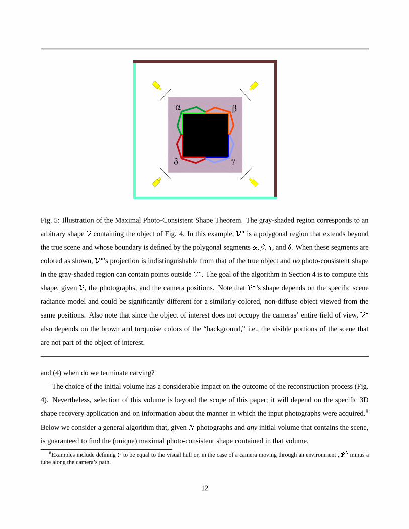
Fig. 5: Illustration of the Maximal Photo-Consistent Shape Theorem. The gray-shaded region corresponds to an
arbitrary shape�
containing the object of Fig. 4. In this example,� �
is a polygonal region that extends beyond
the true scene and whose boundary is defined by the polygonal segments � � � ��� , and � . When these segments are
colored as shown,� �
’s projection is indistinguishable from that of the true object and no photo-consistent shape
in the gray-shaded region can contain points outside� �
. The goal of the algorithm in Section 4 is to compute this
shape, given�
, the photographs, and the camera positions. Note that� �
’s shape depends on the specific scene
radiance model and could be significantly different for a similarly-colored, non-diffuse object viewed from the
same positions. Also note that since the object of interest does not occupy the cameras’ entire field of view,� �
also depends on the brown and turquoise colors of the “background,” i.e., the visible portions of the scene that
are not part of the object of interest.
and (4) when do we terminate carving?
The choice of the initial volume has a considerable impact on the outcome of the reconstruction process (Fig.
4). Nevertheless, selection of this volume is beyond the scope of this paper; it will depend on the specific 3D
shape recovery application and on information about the manner in which the input photographs were acquired.8
Below we consider a general algorithm that, given�
photographs and any initial volume that contains the scene,
is guaranteed to find the (unique) maximal photo-consistent shape contained in that volume.
8Examples include defining�
to be equal to the visual hull or, in the case of a camera moving through an environment ,� �
minus atube along the camera’s path.
12

In particular, let�
be an arbitrary finite volume that contains the scene. We represent�
as a finite collection
of voxels � � ������� � ��� whose surface conforms to a radiance model defined by a consistency check algorithm
consist � � � . Using this representation, each carving iteration removes a single voxel from�
.
The Subset Theorem leads directly to a method for selecting the voxel to carve away from�
at each iteration.
Specifically, the proposition tells us that if a voxel � on the surface of�
is not photo-consistent, the volume� � � � ��� must still contain the maximal photo-consistent shape. Hence, if only non photo-consistent voxels
are removed at each iteration, the carved volume is guaranteed to converge to the maximal photo-consistent shape.
The order in which non-photo-consistent voxels are examined and removed is not important for guaranteeing
correctness. Convergence to this shape occurs when no non-photo-consistent voxel can be found on the surface
of the carved volume. These considerations lead to the following algorithm for computing the maximal photo-
consistent shape:9
Space Carving Algorithm
Step 1: Initialize�
to a superset of the scene.
Step 2: Repeat the following steps until a non-photo-consistent voxel � is found on the surface of�
:
a. Project � to all photographs in Vis � � � � . Let ��� � � ����������������� be the colors at � ’s projection in each photo-
graph and let � � ��������� ��� be the optical rays connecting � to the corresponding optical centers.
b. Determine the photo-consistency of � using consist � � ����� � ������� ����� � � � � � ������� � � � � .
Step 3: If no non-photo-consistent voxel is found, set� � � �
and terminate. Otherwise, set� � � � �� and
continue with Step 2.
The key step in the space carving algorithm is the search and voxel consistency checking of Step 2. The
following proposition gives an upper bound on the number of voxel photo-consistency checks that must be per-
formed during space carving:
Proposition 1 The total number of required photo-consistency checks is bounded by�� �
where�
is the
number of input photographs and�
is the number of voxels in the initial (i.e., uncarved) volume.
Proof: Since (1) the photo-consistency of a voxel � that remains on�
’s surface for several carving iterations can
change only when Vis � � � � changes due to�
’s carving, and (2) Vis � � � � expands monotonically as�
is carved
(Visibility Lemma), the photo-consistency of � must be checked at most�
times. QED
9Convergence to this shape is provably guaranteed only for scenes representable by a discrete set of voxels.
13

(a) (b)
Fig. 6: Visiting voxels in order of visibility. Sweeping a plane � � ��� in the direction of increasing � coordinate
ensures that a voxel � will be visited before every voxel � that it occludes, for all cameras whose optical center
has � coordinate less than � � . To exploit this observation, the photo-consistency of voxels on the sweep plane is
evaluated by considering only those cameras that lie “in front of” this plane (i.e., the cameras drawn in yellow in
(a) and (b)). Intuitively, cameras become “active” when the sweep plane passes over them.
4.1 A Multi-Sweep Implementation of Space Carving
In order to implement the Space Carving Algorithm, the following three operations, performed in Step 2 of the
algorithm, must be supported: (1) determine Surf � � � , (2) compute Vis � � � � for each voxel � � �, and (3) check
to see if � is photo-consistent. Because carving a single voxel can affect global visibility, it is essential to be able
to keep track of visibility information in a way that may be efficiently updated.
To reduce visibility computations, we use a multi-pass algorithm for space carving. Each pass of the algo-
rithm consists of sweeping a plane through the scene volume and testing the photo-consistency of voxels on that
plane. The advantage of this plane-sweep algorithm is that voxels are always visited in an order that captures all
occlusion relations between voxels and an appropriately-chosen subset � of the cameras: each sweep guarantees
that if a voxel � occludes another voxel, � , when viewed from a camera in � , � will necessarily be visited before
� . This is achieved by choosing � to be the set of cameras that lie on one side of the plane in each pass (Fig. 6).
Specifically, consider two voxels � � � ��� � ��� � ���� and � � ���� ��������� �� , such that � occludes � from a camera
14

centered at � � � � � ��� � ��� � . Since the voxel � lies on the line segment with endpoints � and � , the following
relations must hold:
� � � � ��� � � � � ��������� � � ��� ���� �� (1)
� �� � � � � �� � � ������� � � ��� ���� �� (2)
These relations suggest two rules for visiting voxels in the scene volume: (1) evaluate voxels in order of increasing
� coordinate, i.e., group voxels in a series of planes � � � � � � � � � ������� � � � ��� with � � increasing, and (2) for
a given plane � � � � , consider only cameras centered at � such that � � � � � . When these two rules are obeyed,
Eq. (1), ensures that voxels will be visited in order of occlusion (i.e., � before � with respect to any camera � ).Similarly, Eq. (2) tells us that the same holds true when the plane is swept in order of decreasing � coordinate.
Sweeping planes in increasing or decreasing � coordinate does not treat the case where � � � � � � � � . This
can be handled with the help of an additional sweep through the volume in either one of the positive or negative
� or � directions.
Rather than explicitly storing every voxel in the volume, we chose a more efficient data structure that repre-
sents the volume as a collection of 1-D spans. Specifically, the volume is represented as a 2D array � of � span
lists:
��� ����� ��� � ����� �� ��� �� � � ��� �� ��� �� � ��������� ���"!� ���"!� ���Each span ��� �� ��� �� � corresponds to an interval �#� �$� ��� �� � to �#� �$� ��� �� � that is contained within the volume; a
point �#� �$� ��� � lies inside the volume if and only if � is contained in a span of ��� �%��� �&� . Because the algorithm
visits voxels in � and � order, this inside test can be performed in constant time—this is achieved by maintaining
spans in doubly-linked lists, sorted in both increasing and decreasing � .
Note that each plane sweep considers only a subset of the cameras from which a voxel may be visible. In
order to ensure photo-consistency of voxels with all input views, multiple sweeps are needed. Our implementation
cycles through six directions in each pass, i.e., in increasing/decreasing � , � , and � directions, and applies repeated
passes until the carving procedure converges. This typically occurs after 2 or 3 passes.
5 Experimental Results
In this section we present results from applying our volumetric implementation of the Space Carving Algorithm
to two real and one synthetic image sequence. In all examples, a Lambertian model was used for the Consistency
15

(a) (b) (c)
Fig. 7: Reconstruction of a wood sculpture. One of 21 input images is shown (a), along with views of the
reconstruction from similar (b) and overhead (c) views.
Check Criterion, i.e., it was assumed that a voxel projects to pixels of the same color in every image. The standard
deviation of these pixels was therefore used to determine whether or not a voxel should be carved.
We first ran the algorithm on several images of a wooden sculpture to evaluate the performance of our multi-
pass implementation with photographs of a real object. The images were acquired by placing the object on a
calibrated pan-tilt head and rotating it in front of a camera. To facilitate the carving process, the images were
also thresholded to remove black background pixels. Background segmentation is not strictly necessary, as will
be demonstrated in the next experiment. We include this step only to illustrate that background constraints, when
available, are easily integrated into the algorithm.
A high threshold (18% average RGB component error) was used to compensate for calibration error and
strong changes in illumination due to object rotation. Consequently, some fine details were lost in the final recon-
struction. The initial volume,�
, was chosen to be a solid cube containing the sculpture. Fig. 7 shows a selected
input image and new views of the reconstruction,� �
. As can be seen from these images, the reconstruction cap-
tures the shape of the sculpture quite accurately, although fine details like the wood grain are blurred. With the
exception of a few stray voxels, the reconstruction appears quite smooth and connected, in spite of the fact that
no smoothness bias was used by the algorithm. The reconstruction, which required a total of 24 sweeps through
the volume, contains 22000 voxels, all of which lay on the surface of the reconstruction. It took 8 minutes to
16

Fig. 8: A sequence of sixteen 486x720 RGB images of a gargoyle stone sculpture. The sequence corresponds to
a complete rotation of the object in front of a stationary camera, performed in � � � �degree increments.
compute� �
on a 150 MHz R4400 Silicon Graphics Indy workstation.
We next ran the Space Carving Algorithm on 16 images of a gargoyle sculpture (Fig. 8). These images were
acquired by rotating the object in front of a stationary camera and manually altering the object’s background be-
fore each image was acquired. This latter step enabled complete reconstruction of the sculpture without any initial
segmentation step—the space carving process effectively removed all background pixels in all input photographs
because the varying backgrounds ensured that photo-consistency could not be enforced for points projecting to
non-object pixels. The sub-pixel calibration error in this sequence also enabled using a smaller threshold of 6%
for the RGB component error. This threshold, along with the voxel size and the 3D coordinates of a bounding box
containing the object were the only parameters given as input to our implementation. Fig. 9 shows selected input
images and new views of the reconstruction,� �
. This reconstruction consisted of 215 thousand surface voxels
that were carved out of an initial volume of approximately 51 million voxels. It took 250 minutes to compute� �
on an SGI O2 R10000/175MHz workstation.
17

(a) (b)
(c) (d)
Fig. 9: Reconstruction of a gargoyle sculpture. One of 16 input images is shown (a), along with views of the
reconstruction from the same (b) and new (c-d) viewpoints.
18

Note that the near-perfect segmentation achieved through space carving was performed not in image-space,
but in 3D object space—the background lay outside the initial block of voxels and was therefore not recon-
structed. This method of 3D background segmentation has significant advantages over image subtraction and
chroma-keying methods because it (1) does not require the background to be known and (2) will never falsely
eliminate foreground pixels, as these former techniques are prone to do [59]. Some errors are still present in the
reconstruction, notably holes that occur as a result of shadows and other illumination changes. These effects were
not modeled by the Lambertian model and therefore caused voxels on shadowed surfaces to be carved. The finite
voxel size, calibration error, and image discretization effects resulted in a loss of some fine surface detail. Voxel
size could be further reduced with better calibration, but only up to the point where image discretization effects
(i.e., finite pixel size) become a significant source of error.
This experiment highlights a number of advantages of our technique over previous reconstruction approaches.
Existing multi-baseline stereo techniques [1] work best for densely textured scenes and suffer in the presence
of large occlusions. In contrast, the gargoyle sequence contains many low-textured regions and very dramatic
changes in visibility, due to the complete rotation of the object in front of the camera. The low-texture and
occlusion properties also cause problems for feature-based structure-from-motion methods [37, 43, 60, 61], due
to the difficulty of locating and tracking a sufficient number of features throughout the sequence. While volume
intersection [10, 21, 56] and other contour-based techniques [6, 8, 9, 41, 42, 62] are often used successfully in
similar experiments, they require the detection of silhouettes or occluding contours. For the gargoyle sequence,
the background was unknown and heterogeneous, making the contour detection problem extremely difficult. Note
also that Seitz and Dyer’s voxel coloring technique [29] would not work for this sequence because of the camera
configuration, i.e., the scene intersects the convex hull of the camera centers. The Space Carving algorithm
succeeds for this sequence because it integrates both texture and contour information as appropriate, without the
need to explicitly detect features or contours in the images. Our results for both the gargoyle and the wooded
sculpture sequence also suggest that the Space Carving Algorithm performs well both for sequences that contain
significant color variation as well as for sequences where the objects are essentially gray-scale.
In a third experiment, we applied the Space Carving Algorithm to rendered images of a synthetic building
scene. To reconstruct the entire scene, cameras were placed both in the interior and exterior of the building (Fig.
10) and the resulting images were presented to the algorithm in a random order. This placement of cameras
yields an extremely difficult stereo problem, due to the drastic changes in visibility between interior and exterior
cameras.10 The voxel space was initialized to a � ����� ��� ��� � ��� block, containing roughly 7 million voxels. The
10For example, the algorithms in [29, 30] fail catastrophically for this scene because the unconstrained distribution of the input views
19

Fig. 10: Cameras for the building scene. Cameras were placed in both the interior and exterior of a building to
enable simultaneous, complete reconstruction of its exterior and interior surfaces. The viewpoints used by the
carving algorithm are shown in gray; the two red cameras correspond to the building’s views in Figs. 12(a)-(d).
carving process converged after 2 passes, requiring roughly an hour and 40 minutes of computation.11 The final
model contained 370 thousand voxels.
Figs. 11 and 12 compare the original model and the reconstruction from a range of different viewpoints. The
fidelity of the model is very good near the input viewpoints, as demonstrated in Fig. 11 (a)-(d). As one might
expect, the visual quality of the reconstruction degrades for viewpoints far from the input cameras, as shown in
the overhead view (Fig. 13 (b)), but is still quite reasonable. Including the overhead view in the set of input
images and recomputing the reconstruction yields a dramatic improvement in quality, as shown in Fig. 13 (c).
Note that incorporating such a disparate view is straightforward, owing to the unique ability of the Space Carving
Algorithm to integrate images from cameras in arbitrary positions and orientations. Also note that the ability
to incorporate the entire set of input images into a single, unified reconstruction process allows us to generate
novel views of the scene in which the interior and the exterior of the building are visible simultaneously (Fig.
12(a)-(d)).
and the resulting occlusion relationships violate the assumptions used by those algorithms.11In our implementation, convergence occurs when a pass (i.e., 6 plane sweeps) completes with only a small percentage of voxels
carved away during that pass—3% in the case of the building scene.
20

(a) (b)
(c) (d)
Fig. 11: Reconstruction of the building scene. Rendered images of the building (left) are compared to views of the
reconstruction (right). (a) and (c) are two of the input views, from outside and inside the building, respectively.
6 Concluding Remarks
This paper introduced photo-consistency theory as a new, general mathematical framework for analyzing the 3D
shape recovery problem from multiple images. We have shown that this theory leads to a “least commitment”
approach for shape recovery and a practical algorithm called Space Carving that together overcome several lim-
itations in the current state of the art. First, the approach allows us to analyze and characterize the set of all
21

possible reconstructions of a scene, without committing to heuristic shape or camera constraints, and without
committing to a specific algorithm or implementation. Second, this is the only provably-correct method, to our
knowledge, capable of reconstructing non-smooth, free-form shapes from cameras positioned and oriented in a
completely arbitrary way. Third, the performance of the Space Carving Algorithm was demonstrated on real
and synthetic image sequences of geometrically-complex objects, including a large building scene photographed
from both interior and exterior viewpoints. Fourth, the use of photo-consistency as a criterion for 3D shape re-
covery enables the development of reconstruction algorithms that allow faithful image reprojections and resolve
the complex interactions between occlusion, parallax, and shading effects in shape analysis.
While the Space Carving Algorithm’s effectiveness was demonstrated in the presence of image noise, the
photo-consistency theory itself is based on an idealized model of image formation. Extending the theory to
explicitly model image noise, quantization and calibration errors, and their effects on the maximally consistent
shape is an open research problem. Extending the formulation to handle non-locally computable radiance models
(e.g., shadows) is another important topic of future work. Other research directions include (1) developing optimal
space carving algorithms for noisy images, (2) investigating the use of surface-based rather than voxel-based
techniques for finding the maximal photo-consistent shape, (3) using a priori shape constraints (e.g., smoothness)
to refine that shape, and (4) analyzing the topological structure of the family of photo-consistent shapes.
22

(a) (b)
(c) (d)
Fig. 12: Views from viewpoints near the input cameras. Rendered images of the building (left) are compared toviews of the reconstruction (right). The views in (a) and (c) correspond to the (non-input) red cameras in Fig. 10.
(a) (b) (c)
Fig. 13: Views of the reconstruction from far away camera viewpoints. (a) shows a rendered top view of thebuilding, (b) the same view of the reconstruction, and (c) a new reconstruction resulting from adding image(a) to the set of input views. Note that adding a single top view drastically improves the visual quality of thereconstruction.
23

References
[1] M. Okutomi and T. Kanade, “A multiple-baseline stereo,” IEEE Trans. Pattern Anal. Machine Intell., vol. 15,no. 4, pp. 353–363, 1993.
[2] K. N. Kutulakos and C. R. Dyer, “Recovering shape by purposive viewpoint adjustment,” Int. J. ComputerVision, vol. 12, no. 2, pp. 113–136, 1994.
[3] T. Poggio, V. Torre, and C. Koch, “Computational vision and regularization theory,” Nature, vol. 317, no. 26,pp. 314–319, 1985.
[4] R. C. Bolles, H. H. Baker, and D. H. Marimont, “Epipolar-plane image analysis: An approach to determiningstructure from motion,” Int. J. Computer Vision, vol. 1, pp. 7–55, 1987.
[5] A. Katayama, K. Tanaka, T. Oshino, and H. Tamura, “A viewpoint dependent stereoscopic display usinginterpolation of multi-viewpoint images,” in Proc. SPIE, vol. 2409A, pp. 21–30, 1995.
[6] B. Bascle and R. Deriche, “Stereo matching, reconstruction and refinement of 3D curves using deformablecontours,” in Proc. 4th Int. Conf. Computer Vision, pp. 421–430, 1993.
[7] P. Pritchett and A. Zisserman, “Wide baseline stereo matching,” in Proc. 6th Int. Conf. on Computer Vision,pp. 754–760, 1998.
[8] R. Cipolla and A. Blake, “Surface shape from the deformation of apparent contours,” Int. J. ComputerVision, vol. 9, no. 2, pp. 83–112, 1992.
[9] R. Vaillant and O. D. Faugeras, “Using extremal boundaries for 3-d object modeling,” IEEE Trans. PatternAnal. Machine Intell., vol. 14, no. 2, pp. 157–173, 1992.
[10] A. Laurentini, “The visual hull concept for silhouette-based image understanding,” IEEE Trans. PatternAnal. Machine Intell., vol. 16, no. 2, pp. 150–162, 1994.
[11] R. Szeliski and R. Weiss, “Robust shape recovery from occluding contours using a linear smoother,” inReal-time Computer Vision (C. M. Brown and D. Terzopoulos, eds.), pp. 141–165, Cambridge UniversityPress, 1994.
[12] K. N. Kutulakos and C. R. Dyer, “Global surface reconstruction by purposive control of observer motion,”Artificial Intelligence Journal, vol. 78, no. 1-2, pp. 147–177, 1995.
[13] P. N. Belhumeur, “A bayesian approach to binocular stereopsis,” Int. J. on Computer Vision, vol. 19, no. 3,pp. 237–260, 1996.
[14] I. Cox, S. Hingorani, S. Rao, and B. Maggs, “A maximum likelihood stereo algorithm,” CVIU: ImageUnderstanding, vol. 63, no. 3, pp. 542–567, 1996.
[15] C. V. Stewart, “MINPRAN: A new robust estimator for computer vision,” IEEE Trans. Pattern Anal. Ma-chine Intell., vol. 17, no. 10, pp. 925–938, 1995.
[16] J. D. Foley, A. van Dam, S. K. Feiner, and J. F. Hughes, Computer Graphics Principles and Practice.Addison-Wesley Publishing Co., 1990.
[17] K. E. Torrance and E. M. Sparrow, “Theory of off-specular reflection from roughened surface,” Journal ofthe Optical Society of America, vol. 57, pp. 1105–1114, 1967.
24

[18] J. J. Koenderink and A. J. van Doorn, “Affine structure from motion,” J. Opt. Soc. Am., vol. A, no. 2,pp. 377–385, 1991.
[19] J. L. Mundy and A. Zisserman, eds., Geometric Invariance in Computer Vision. MIT Press, 1992.
[20] W. Hoff and N. Ahuja, “Surfaces from stereo: Integrating feature matching, disparity estimation, and con-tour detection,” IEEE Trans. Pattern Anal. Machine Intell., vol. 11, pp. 121–136, 1989.
[21] R. Szeliski, “Rapid octree construction from image sequences,” CVGIP: Image Understanding, vol. 58,no. 1, pp. 23–32, 1993.
[22] R. Epstein, A. L. Yuille, and P. N. Belhumeur, “Learning object representations from lighting variations,” inObject Representation in Computer Vision II (J. Ponce, A. Zisserman, and M. Hebert, eds.), pp. 179–199,Springer-Verlag, 1996.
[23] P. N. Belhumeur and D. J. Kriegman, “What is the set of images of an object under all possible lightingconditions,” in Proc. Computer Vision and Pattern Recognition, pp. 270–277, 1996.
[24] R. J. Woodham, Y. Iwahori, and R. A. Barman, “Photometric stereo: Lambertian reflectance and lightsources with unknown direction and strength,” Tech. Rep. 91-18, University of British Columbia, Labora-tory for Computational Intelligence, August 1991.
[25] R. C. Bolles and R. A. Cain, “Recognizing and locating partially-visible objects: The local-feature-focusmethod,” Int. J. Robotics Research, vol. 1, no. 3, pp. 57–82, 1982.
[26] T. Kanade, A. Yoshida, K. Oda, H. Kano, and M. Tanaka, “A stereo machine for video-rate dense depthmapping and its new applications,” in Proc. Computer Vision and Pattern Recognition Conf., 1996.
[27] P. Fua and Y. G. Leclerc, “Object-centered surface reconstruction: Combining multi-image stereo and shad-ing,” Int. J. Computer Vision, vol. 16, pp. 35–56, 1995.
[28] R. T. Collins, “A space-sweep approach to true multi-image matching,” in Proc. Computer Vision andPattern Recognition Conf., pp. 358–363, 1996.
[29] S. M. Seitz and C. R. Dyer, “Photorealistic scene reconstruction by voxel coloring,” in Proc. ComputerVision and Pattern Recognition Conf., pp. 1067–1073, 1997.
[30] S. M. Seitz and K. N. Kutulakos, “Plenoptic image editing,” in Proc. 6th Int. Conf. Computer Vision, pp. 17–24, 1998.
[31] C. L. Zitnick and J. A. Webb, “Multi-baseline stereo using surface extraction,” Tech. Rep. CMU-CS-96-196,Carnegie Mellon University, Pittsburgh, PA, November 1996.
[32] P. J. Narayanan, P. W. Rander, and T. Kanade, “Constructing virtual worlds using dense stereo,” in Proc.Int. Conf. on Computer Vision, pp. 3–10, 1998.
[33] R. Szeliski and P. Golland, “Stereo matching with transparency and matting,” in Proc. 6th Int. Conf. onComputer Vision, pp. 517–524, 1998.
[34] S. Roy and I. J. Cox, “A maximum-flow formulation of the N-camera stereo correspondence problem,” inProc. 6th Int. Conf. on Computer Vision, pp. 492–499, 1998.
25

[35] O. D. Faugeras and R. Keriven, “Variational principles, surface evolution, pde’s, level set methods and thestereo problem,” IEEE Trans. Image Processing, vol. 7, no. 3, pp. 336–344, 1998.
[36] O. D. Faugeras and S. Maybank, “Motion from point matches: multiplicity of solutions,” Int. J. ComputerVision, vol. 4, pp. 225–246, 1990.
[37] S. M. Seitz and C. R. Dyer, “Complete scene structure from four point correspondences,” in Proc. 5th Int.Conf. on Computer Vision, pp. 330–337, 1995.
[38] B. Curless and M. Levoy, “A volumetric method for building complex models from range images,” in Proc.SIGGRAPH’96, pp. 303–312, 1996.
[39] G. Turk and M. Levoy, “Zippered polygon meshes from range images,” in Proc. SIGGRAPH’94, pp. 311–318, 1994.
[40] T. Kanade, P. J. Narayanan, and P. W. Rander, “Virtualized reality: Concepts and early results,” in Proc.Workshop on Representations of Visual Scenes, pp. 69–76, 1995.
[41] C. Zhao and R. Mohr, “Global three-dimensional surface reconstruction from occluding contours,” Com-puter Vision and Image Understanding, vol. 64, no. 1, pp. 62–96, 1996.
[42] W. B. Seales and O. Faugeras, “Building three-dimensional object models from image sequences,” Com-puter Vision and Image Understanding, vol. 61, no. 3, pp. 308–324, 1995.
[43] C. Tomasi and T. Kanade, “Shape and motion from image streams under orthography: A factorizationmethod,” Int. J. Computer Vision, vol. 9, no. 2, pp. 137–154, 1992.
[44] S. Moezzi, A. Katkere, D. Y. Kuramura, and R. Jain, “Reality modeling and visualization from multiplevideo sequences,” IEEE Computer Graphics and Applications, vol. 16, no. 6, pp. 58–63, 1996.
[45] Z. Zhang, “Image-based geometrically-correct photorealistic scene/object modeling (ibphm): A review,” inProc. 3rd Asian Conf. on Computer Vision, pp. 340–349, 1998.
[46] S. B. Kang and R. Szeliski, “3-D scene data recovery using omnidirectional multibaseline stereo,” in Proc.Computer Vision and Pattern Recognition Conf., pp. 364–370, 1996.
[47] Y. Sato, M. D. Wheeler, and K. Ikeuchi, “Object shape and reflectance modeling from observation,” in Proc.SIGGRAPH’97, pp. 379–387, 1997.
[48] O. D. Faugeras, “Personal communication.”
[49] R. L. Alfvin and M. D. Fairchild, “Observer variability in metameric color matches using color reproductionmedia,” Color Research & Application, vol. 22, no. 3, pp. 174–178, 1997.
[50] J. A. J. C. van Veen and P. Werkhoven, “Metamerisms in structure-from-motion perception,” Vision Re-search, vol. 36, no. 14, pp. 2197–2210, 1996.
[51] Y. Aloimonos, “Visual shape computation,” Proc. IEEE, vol. 76, pp. 899–916, 1988.
[52] D. Marr, Vision. Freeman, 1982.
[53] P. E. Debevec, C. J. Taylor, and J. Malik, “Modeling and rendering architecture from photographs: A hybridgeometry- and image-based approach,” in Proc. SIGGRAPH’96, pp. 11–20, 1996.
26

[54] I. A. Kakadiaris and D. Metaxas, “3D human body model acquisition from multiple views,” in Proc. Int.Conf. on Computer Vision, pp. 618–623, 1995.
[55] O. Faugeras, “Stratification of three-dimensional vision: projective, affine, and metric representations,” J.Opt. Soc. Am. A, vol. 12, no. 3, pp. 465–484, 1995.
[56] W. N. Martin and J. K. Aggarwal, “Volumetric descriptions of objects from multiple views,” IEEE Proc.Pattern Anal. Machine Intell., vol. 5, no. 2, pp. 150–158, 1983.
[57] K. N. Kutulakos, “Shape from the light field boundary,” in Proc. Computer Vision and Pattern Recognition,pp. 53–59, 1997.
[58] S. J. Gortler, R. Grzeszczuk, R. Szeliski, and M. F. Cohen, “The lumigraph,” in Proc. SIGGRAPH’96,pp. 43–54, 1996.
[59] A. R. Smith and J. F. Blinn, “Blue screen matting,” in Proc. SIGGRAPH’96, pp. 259–268, 1996.
[60] P. Beardsley, P. Torr, and A. Zisserman, “3D model acquisition from extended image sequences,” in Proc.4th European Conf. on Computer Vision, pp. 683–695, 1996.
[61] M. Pollefeys, R. Koch, and L. V. Gool, “Self-calibration and metric reconstruction in spite of varying andunknown internal camera parameters,” in Proc. 6th Int. Conf. on Computer Vision, pp. 90–95, 1998.
[62] R. Szeliski and R. Weiss, “Robust shape recovery from occluding contours using a linear smoother,” inProc. Computer Vision and Pattern Recognition Conf., pp. 666–667, 1993.
27