a text book of
TRANSCRIPT


A TEXT BOOK OF
PPOOWWEERR
EELLEECCTTRROONNIICCSS
FOR
SEMESTER – II
TTHHIIRRDD YYEEAARR DDEEGGRREEEE CCOOUURRSSEE IINN
EELLEECCTTRROONNIICCSS AANNDD TTEELLEECCOOMMMMUUNNIICCAATTIIOONN
AND
SEMESTER – I
EELLEECCTTRROONNIICCSS EENNGGIINNEEEERRIINNGG
Strictly According to New Revised Credit System Syllabus
of Savitribai Phule Pune University (w.e.f. June 2017)
S. D. SAWANT K. P. AKOLE M. Tech. (Power Electronics) B. E. (E & Tc), M.E. (Comp.), M.I.E.T.E., M.I.E.
Head, E & Tc Deptt., Lecturer, Electronics Department,
STES's NBN Sinhgad School of Engineering, Government Polytechnic,
Ambegaon (Bk), Pune. Jalgaon.
Price `̀̀̀ 165.00
N4206

POWER ELECTRONICS (TE E & Tc SEM. II / ELECTRONICS SEM. I) ISBN : 978-93-87397-21-7
First Edition : January 2018
© : Authors The text of this publication, or any part thereof, should not be reproduced or transmitted in any form or stored in any computer storage system or device for distribution
including photocopy, recording, taping or information retrieval system or reproduced on any disc, tape, perforated media or other information storage device etc., without the
written permission of Authors with whom the rights are reserved. Breach of this condition is liable for legal action.
Every effort has been made to avoid errors or omissions in this publication. In spite of this, errors may have crept in. Any mistake, error or discrepancy so noted and shall
be brought to our notice shall be taken care of in the next edition. It is notified that neither the publisher nor the authors or seller shall be responsible for any damage or loss of
action to any one, of any kind, in any manner, therefrom.
Published By : Polyplate Printed By :
NIRALI PRAKASHAN YOGIRAJ PRINTERS AND BINDERS
Abhyudaya Pragati, 1312, Shivaji Nagar, Survey No. 10/1A, Ghule Industrial Estate
Off J.M. Road, Pune – 411005 Nanded Gaon Road
Tel - (020) 25512336/37/39, Fax - (020) 25511379 Nanded, Pune - 411041
Email : [email protected] Mobile No. 9404233041/9850046517
☞☞☞☞ DISTRIBUTION CENTRES PUNE
Nirali Prakashan : 119, Budhwar Peth, Jogeshwari Mandir Lane, Pune 411002, Maharashtra
Tel : (020) 2445 2044, 66022708, Fax : (020) 2445 1538
Email : [email protected], [email protected]
Nirali Prakashan : S. No. 28/27, Dhyari, Near Pari Company, Pune 411041
Tel : (020) 24690204 Fax : (020) 24690316
Email : [email protected], [email protected]
MUMBAI
Nirali Prakashan : 385, S.V.P. Road, Rasdhara Co-op. Hsg. Society Ltd.,
Girgaum, Mumbai 400004, Maharashtra
Tel : (022) 2385 6339 / 2386 9976, Fax : (022) 2386 9976
Email : [email protected]
☞☞☞☞ DISTRIBUTION BRANCHES JALGAON
Nirali Prakashan : 34, V. V. Golani Market, Navi Peth, Jalgaon 425001,
Maharashtra, Tel : (0257) 222 0395, Mob : 94234 91860
KOLHAPUR
Nirali Prakashan : New Mahadvar Road, Kedar Plaza, 1st Floor Opp. IDBI Bank
Kolhapur 416 012, Maharashtra. Mob : 9850046155
NAGPUR
Pratibha Book Distributors : Above Maratha Mandir, Shop No. 3, First Floor,
Rani Jhanshi Square, Sitabuldi, Nagpur 440012, Maharashtra
Tel : (0712) 254 7129
DELHI
Nirali Prakashan : 4593/21, Basement, Aggarwal Lane 15, Ansari Road, Daryaganj
Near Times of India Building, New Delhi 110002
Mob : 08505972553
BENGALURU
Pragati Book House : House No. 1, Sanjeevappa Lane, Avenue Road Cross,
Opp. Rice Church, Bengaluru – 560002.
Tel : (080) 64513344, 64513355,Mob : 9880582331, 9845021552
Email:[email protected]
CHENNAI
Pragati Books : 9/1, Montieth Road, Behind Taas Mahal, Egmore,
Chennai 600008 Tamil Nadu, Tel : (044) 6518 3535,
Mob : 94440 01782 / 98450 21552 / 98805 82331,
Email : [email protected]
[email protected] | www.pragationline.com Also find us on www.facebook.com/niralibooks

PREFACE
It gives us great pleasure to present the book 'Power Electronics' for the students of Third Year Degree Course in
Electronics and Telecommunication / Electronics Engineering of the Savitribai Phule Pune University. This book is strictly as
per the New Revised Credit System Syllabus 2015 Pattern with effect from the Academic Year 2017-18.
As per New Revised Examination Scheme which has been implemented from this academic year, In-semester
assessment carries 30 marks over first three units and End Semester Examination carries 70 marks over entire
syllabus out of which first three units will carry 20 marks and units 4, 5, 6 will carry 50 marks. The theory course
will have 4 credits.
The book is written such that all the basic concepts are explained in simplified manner. It is presented in a more
conceptual manner rather than mathematical, as required by the new examination system. It is our objective to keep the
presentation systematic, consistent, intensive and clear through explanatory notes and figures.
Main feature of this book is, Complete Coverage of the New Credit System Syllabus with large number of
Worked Solved Examples, Exercises, Model Question Papers of In Sem. and End Sem. Exams.
We are sure that this book will cater to all needs of students for this subject.
We also take this opportunity to express our sincere thanks to Shri. Dineshbhai Furia, Shri. Jignesh Furia,
Mrs. Nirali Verma, Shri. M. P. Munde and entire team of Nirali Prakashan namely Mrs. Deepali Lachake (Co-ordinator), who
really have taken keen interest and untiring efforts in publishing this text.
The advice and suggestions of our esteemed readers to improve the text are most welcomed, and will be highly
appreciated.
Pune Authors


SYLLABUS
(TE E & Tc SEM. II)
Unit I : Power Devices (8 Hrs)
Construction, Steady state characteristics and Switching characteristics of SCR, Construction, Steady state characteristics of
Power MOSFET and IGBT. SCR ratings: IL, IH, VBO, VBR, dv/dt, di/dt, surge current and rated current. Gate characteristics,
Gate drive requirements, Gate drive circuits for Power MOSFET and IGBT, opto isolator driving circuits for SCR. Series and
parallel operations of SCR‘s. Applications of above power devices as a switch .
Unit II : AC-DC Power Converters (8 Hrs)
Concept of line and forced commutation, Single phase Semi and Full converters for R, R-L loads, Performance parameters,
Effect of freewheeling diode, Three phase Semi and Full converters for R load, effect of source inductance, Power factor
improvement techniques, Diode based boost converter. Single Phase dual converter with inductive load.
Unit III : DC-AC Converters (8 Hrs)
Single phase bridge inverter for R and R-L load using MOSFET / IGBT, performance Parameters, single phase PWM
inverters. Three Phase voltage source inverter for balanced star R load with 120̊ and 180 mode of operation, Device
utilization factor, Harmonics Elimination/Modulation Techniques.
Unit IV : DC-DC Converters and AC Voltage Controller (8 Hrs)
Working Principle of step down chopper for R-L load (highly inductive), control strategies. Performance parameters, Step
up chopper, 2-quadrant and 4-quadrant choppers, SMPS: Fly back/ Half Bridge/ LM3524 based or equivalent Circuit.
Single-Phase full wave AC voltage controller by using IGBT with R load.
Unit V : Resonant Converters and Protection of Power Devices and Circuits (8 Hrs)
Need for Resonant converters, Concept of Zero current switching (ZCS) and Zero voltage switching (ZVS) resonant
converters. Cooling and heat sinks, over voltage conditions, over voltage protection circuits, metal oxide varistors, over
current fault conditions, Over current protection. Electromagnetic interference, sources, minimizing techniques, shielding
techniques for EMI.
Unit VI : Power Electronics Applications (8 Hrs)
ON-line and OFF line UPS with battery AH, back up time, battery charger rating. Electronic Ballast, LED Lamp with Driver
Circuit, fan Regulator. Single phase separately excited DC motor drive, stepper motor drive, BLDC motor drive. Variable
voltage and variable frequency three phase induction motor drive.

SYLLABUS
(TE ELECTRONICS SEM. I)
Perquisites : 1L
Three phase supply: 3 phase 3 wire connection, 3 phase 4 wire connection ,single phase supply, DC supply and their
measurement, Power factor and its significance.
Unit I : Overview of Power Electronics and Power Devices 8L
Power Electronic System: Power Electronics Versus linear electronics, scope and applications, Interdisciplinary nature of
power electronics, classification of power converters Power MOSFET: Construction, Operation, Static characteristics,
switching characteristics, Breakdown voltages, Safe Operating Area, applications IGBT: Construction, Operation, Steady
state characteristics, Switching characteristics, Safe operating area, applications, Base drive circuits, for Power MOSFET /
IGBT. SCR: Construction, Operation and characteristics, two transistor analogy, different ratings, TRIAC: Construction,
Operation and characteristics, applications.
Unit II : Gate Drive Circuits and Protection Circuits for Power Devices 7L
Gate drive Circuits for SCR/TRIAC: Need, requirements, Isolation of Gate and base drives using pulse transformers and
opto-coupler, Synchronized UJT triggering for SCR, triggering of SCR/TRIAC using dedicated triggering ICs, TRIAC
triggering using DIAC. Typical Gate drive circuits for Power MOSFET / IGBT. Microprocessor based control circuits for power
electronics applications. Protection circuits for Power Devices: Cooling and heat sinks. Snubber circuits, reverse recovery
transients, supply and load side transients. Voltage protection by selenium diodes and MOVs. Current protections – fusing,
fault current with AC source, fault current with DC source.
Unit III : AC-DC Power Converters 7L
Uncontrolled and controlled rectifiers need and applications Single phase Semi and Full converters for R, R-L loads,
Concept of line and forced commutation, Effect of freewheeling diode, Performance parameters, Three phase Semi and Full
converters for R and RL load. Design of Control circuit for single phase and three phase controlled rectifiers, Applications of
controlled rectifiers.
Unit IV : DC-AC Converters and AC Voltage Controller 7L
DC-AC Converters: Single phase full bridge inverter for R and R-L loads, performance parameters, three phase voltage
source inverter for balanced star R load. Variable frequency control of three phase inverters, Need of PWM inverters.
Voltage control of Inverters using PWM, three phase PWM inverters. Design of control circuit design for three phase
inverters, PWM ICs. AC Voltage Controller: Single phase AC voltage controller with R load.
Unit V : DC-DC Converters 7L
DC-DC converters: Working principle of step down chopper for R-L load, control strategies. Performance parameters, Buck
converter, Buck-Boost converter, 2-quadrant and 4-quadrant choppers, Applications of choppers, SMPS. Buck regulator
e.g. TPS54160, Switching Regulator and characteristics of standard regulator ICs – TPS40200, Low Drop out (LDO)
Regulators ICs-TPS 7A4901.
Unit VI : Power Electronics Applications 6L
HVDC transmission system. UPS: ON-line and OFF line UPS with battery AH, back up time, battery charger rating. Power
Electronics in Battery Charging Applications, Power Electronics in Induction heating, Electronic lamp ballast. Power
Electronics for Electric drive applications: Overview of electric drive system, Classification of drives, Selection of power
converters for different drive applications (introductory level only).

CONTENTS Unit I : Power Devices 1.1 – 1.36
1.1 Introduction 1.1
1.2 Introduction to Power Electronics 1.2
1.3 Applications of Power Electronics 1.2
1.4 Merits and Demerits of Power Electronic Controller 1.3
1.4.1 Merits 1.3
1.4.2 Demerits 1.3
1.5 Classification of Power Electronic Converters 1.3
1.5.1 Diode Rectifier 1.3
1.5.2 Phase Controlled Rectifier 1.3
1.5.3 DC Chopper (DC-to-DC Converter) 1.3
1.5.4 Inverters (DC to AC Converter) 1.4
1.5.5 AC to AC Converter 1.4
1.6 Power Diode 1.4
1.6.1 V-I Characteristics of Power Diode 1.5
1.6.2 Diode Reverse Recovery Characteristics 1.5
1.7 Classification of Power Diodes 1.6
1.7.1 General Purpose Diode or Standard Diode 1.6
1.7.2 Fast Recovery Diode 1.6
1.7.3 Schottky Diode 1.6
1.8 Thyristor 1.7
1.8.1 Silicon Controlled Rectifier (SCR) 1.7
1.8.2 Static V-I Characteristics of SCR and Operation Steps 1.7
1.8.3 Some Important Parameters of SCR 1.8
1.8.4 Two Transistor Analogy or Model of SCR 1.9
1.8.5 Triggering or Turn-ON Methods of Thyristor 1.9
1.8.6 Pulse Triggering 1.10
1.8.7 Turn-On Characteristics of SCR 1.10
1.8.8 Turn-OFF Characteristics of SCR 1.11
1.9 Power MOSFETs 1.11
1.9.1 Operation of n-Channel Depletion MOSFET 1.12
1.9.2 MOSFET Characteristics 1.12
1.9.3 Merits, Demerits and Applications of MOSFETs 1.13
1.9.4 Comparison of MOSFET with BJT 1.13
1.10 Insulated Gate Bipolar Transistor (IGBT) 1.13
1.10.1 Physics of Device Operation of IGBT 1.14
1.10.2 IGBT Characteristics 1.14
1.10.3 Advantages, Disadvantages and Applications of IGBT 1.16
1.10.4 Comparison between Non-Punch through IGBT (NPT-IGBT) and Punch through IGBT (PT-IGBT 1.16
1.10.5 Latch-Up in IGBTs 1.16
1.10.6 Safe Operating Area of IGBT 1.17
1.10.7 Comparison between MOSFET and IGBT 1.17
1.11 Thyristor Ratings 1.17
1.11.1 Voltage Ratings 1.18
1.11.2 Current Ratings 1.18
1.12 Gate Characteristics of SCR 1.18
1.13 Gate Drive Requirements 1.19
1.14 Comparison between R Triggering, RC Triggering and UJT Based Triggering Methods 1.21
1.14.1 Comparison between MOSFET with SCR 1.22
1.14.2 Comparison between SCR and IGBT 1.22
1.15 Gate Drive Circuits for Power MOSFET and IGBT 1.22
1.15.1 Gate and Device Capacitances 1.22
1.15.2 Driver Circuit Requirements 1.23
1.15.3 MOSFET / IGBT Driver Circuit 1.24
1.15.4 IGBT Protection Circuits 1.24
1.16 OPTO Isolator Driver Circuit for SCR 1.24
1.17 Series and Parallel Operation of SCR’S 1.25
1.18 Thyristor Protection 1.26
1.19 Triggering of SCR Using IC-785 1.27
1.19.1 Block Diagram/Internal Structure of TCA 785 IC 1.27
1.19.2 Triggering Circuit for Single-Phase Controller using IC TCA 785 1.28
1.20 Application of Power Devices as a Switch 1.29
•••• Summary 1.35
•••• Exercise 1.35
•••• University Questions 1.36

Unit II : AC-DC Power Converters 2.1 – 2.42
2.1 Introduction 2.1
2.2 Classification 2.1
2.3 Concept of Line and Force Commutation 2.1
2.3.1 Line Commutation or Natural Commutation 2.1
2.3.2 Forced Commutation 2.2
2.3.3 Requirements of Successful Commutation 2.2
2.4 Single-Phase Half-Wave Converter 2.2
2.4.1 Single-Phase Half-Wave Converter (Rectifier) with Resistive Load 2.2
2.4.2 Single-Phase Half-Wave Rectifier with RL Load 2.3
2.4.3 Single-Phase Half-Wave Rectifier with RL Load and Free-Wheeling Diode 2.4
2.4.4 Single-Phase Half-Wave Rectifier with RLE Load (Active Load) 2.5
2.5 Single-Phase Full-Wave Controlled Converter (Rectifier) 2.6
2.5.1 Single-Phase Full-Wave Controlled Rectifier with R Load
[Mid-Point Converter or Single-Phase Two Pulse Converter] 2.6
2.5.2 Single-Phase Full-Wave Controlled Rectifier with RL Load (Mid-Point Converter with RL Load) 2.7
2.5.3 Single-Phase Full-Wave Controlled Rectifier with RL Load and Free-Wheeling Diode 2.8
2.6 Quadrant Operation of Converters 2.8
2.7 Single-Phase Full-Wave, Controlled Bridge (Converter) Rectifier 2.9
2.7.1 Single-Phase Fully Controlled Bridge Rectifier with R Load 2.9
2.7.2 Single-Phase Fully Controlled Bridge Rectifier with RL Load 2.10
2.8 Single-Phase Half Controlled Bridge Converter or Semi-Converter 2.11
2.8.1 Comparison between Symmetrical and Asymmetrical Configuration of Semi-Converter 2.11
2.8.2 Single-Phase Half-Controlled Bridge Rectifier with R Load 2.11
2.8.3 Single-Phase Half-Controlled Bridge Rectifier with RL Load 2.12
2.8.4 Comparison between Full-Controlled and Half-Controlled Converter Circuits 2.13
2.8.5 Applications of Rectifiers 2.13
2.9 Effect of Source Inductance in Single-phase Fully-Controlled Converter (Rectifier) 2.13
2.10 Three-Phase Converters 2.14
2.10.1 Three-Phase Half-Wave Controlled Converter (With Highly Inductive Load) 2.14
2.10.2 Three-phase Half-wave Controlled Converter with R Load 2.16
2.11 Three-Phase Semi-Converters or Three-Phase Half-Controlled Bridge Converter 2.17
2.11.1 Three-Phase, Half-Controlled Bridge Converter with Highly Inductive Load 2.17
2.11.2 Three-Phase Semi-Converter or Three-Phase Half-controlled Bridge Converter with Purely Resistive Load 2.18
2.12 Three-Phase Fully-Controlled Bridge Converter with Highly Inductive Load 2.19
2.12.1 Three Phase Fully Controlled Bridge Converter with Highly Resistive Load 2.20
2.12.2 Comparison of Three-Phase and Single-Phase Converters 2.21
2.13 Three-Phase Dual Converter 2.22
2.14 Effect of Source Inductance on Three-Phase Fully-Controlled Bridge Converter 2.23
2.15 Power Factor Improvement Techniques 2.23
2.16 Diode Based Boost Converter 2.25
2.17 Single-Phase Dual Converter 2.27
2.17.1 Single Phase Dual Converter with Inductive Load 2.27
•••• Summary 2.40
•••• Exercise 2.41
•••• University Questions 2.42
Unit III : DC-AC Converters 3.1 – 3.22
3.1 Introduction 3.1
3.2 Classification of Inverters 3.1
3.3 Half Bridge Inverter with 'R' Load 3.1
3.4 Half Bridge Inverter with RL Load 3.2
3.5 Single Phase Bridge Inverter 3.4
3.6 Single Phase Bridge Inverter with RL Load 3.5
3.7 Performance Parameters 3.7
3.8 Single Phase PWM (Pulse Width Modulation) Inverters 3.8
3.8.1 Harmonic Elimination / Modulation Technique 3.8
3.9 Three Phase Voltage Source Inverter for Balanced Star R-Load 3.11
3.9.1 Three-Phase 180° Mode Bridge Inverter 3.11
3.9.2 Three-Phase 120° Mode Bridge Inverter 3.14
3.9.3 Comparison of 120° and 180° Modes of Conduction 3.16
3.10 Device Utilization Factor 3.16
3.11 Applications of Inverters 3.16
•••• Summary 3.19
•••• Exercise 3.20
•••• University Questions 3.21

Unit IV : DC-DC Converters and AC Voltage Controller 4.1 – 4.36
4.1 Introduction 4.1
4.2 General Features and Applications of DC Choppers 4.1
4.3 Classification of Choppers 4.1
4.4 Principle of Chopper Operation (Step-Down Chopper) 4.1
4.4.1 Continuous and Discontinuous Condition of Step-Down Chopper or Type A Chopper 4.3
4.5 Control Strategies 4.4
4.5.1 Performance Parameters 4.4
4.6 Step-Up Chopper 4.4
4.7 Types of Chopper 4.5
4.7.1 Type A Chopper (First Quadrant Chopper) 4.5
4.7.2 Type B Chopper (Second Quadrant Chopper) 4.6
4.7.3 Type A or Type C Chopper (Two Quadrant Chopper) 4.6
4.7.4 Type B or Type D Chopper (Two Quadrant Chopper) 4.6
4.7.5 Type E Chopper or Four Quadrant Chopper 4.7
4.8 Multiphase Chopper 4.7
4.9 Forced Commutated Thyristor-Based Chopper 4.8
4.9.1 Voltage or Impulse Commutated Chopper 4.8
4.9.2 Current Commutated Chopper 4.10
4.9.3 Load Commutated Chopper 4.11
4.10 Use of Filter on the Input Side of Chopper 4.12
4.11 Switched-Mode Power Supply (SMPS) 4.13
4.11.1 Advantages of SMPS over Linear Power Supply 4.14
4.11.2 Classification of SMPS 4.15
4.12 Introduction to Single Phase AC-AC Power Controller 4.17
4.13 Types of AC Voltage Controller 4.18
4.14 Features, Merits, Demerits and Applications of AC Voltage Controller 4.18
4.14.1 Merits and Demerits of AC Voltage Controller 4.18
4.14.2 Features of AC Voltage Controller 4.18
4.14.3 Effect of Load and Source Inductance 4.18
4.14.4 Applications of AC Voltage Controller 4.18
4.15 On-Off or Integral Cycle Control (ICC) 4.18
4.15.1 Merits and Demerits of On-Off Controller 4.19
4.16 Principle of Phase Controlled Switching or Single-Phase Half-Wave AC Voltage Controller with R-Load 4.20
4.16.1 Comparison between ON-OFF Control and Phase Angle Control 4.21
4.17 Single-Phase Full-Wave AC Voltage Controller with R-Load (Or Bidirectional AC Voltage Controller) 4.21
4. 18 Other Forms of Full-Wave Voltage Controller 4.22
4.18.1 Merits, Demerits and Applications of Full-Wave Controller 4.23
4.19 Single-Phase Full-Wave AC Voltage Controller with RL-Load (OR Bidirectional AC Voltage Controller with RL-Load) 4.23
4.19.1 Comparison between Half-Wave and Full-Wave AC Voltage Controller 4.25
4.20 Single Phase Full Wave AC Voltage Controller by using IGBT with R Load 4.25
•••• Summary 4.34
•••• Exercise 4.35
•••• University Questions 4.36
Unit V : Resonant Converters and Protection of Power Devices and Circuits 5.1 – 5.18
5.1 Introduction 5.1
5.2 Need for Resonant Converters 5.1
5.2.1 Classification of Resonant Converters 5.1
5.2.2 Advantages of Resonant Converter 5.1
5.2.3 Disadvantages 5.1
5.3 Resonant Tank Circuit 5.1
5.3.1 Series Resonant Tank (Second Order Tank) 5.2
5.3.2 Parallel Resonant Tank (Second Order Tank) 5.2
5.3.3 Third Order Resonant Tank 5.2
5.4 Series Resonant (SLR) Half Bridge DC-DC Converter 5.2
5.5 Comparison between Linear, Switched Mode and Resonant Converters 5.3
5.6 Resonant Switch Converters 5.3
5.6.1 Zero Voltage Switching (ZVS) Resonant Converters 5.4
5.6.2 Zero Current Switching (ZCS) Resonant Converter 5.6
5.6.3 Comparison between ZVS and ZCS Resonant Converter 5.7
5.7 Cooling and Heat Sinks 5.7
5.7.1 Thermal Resistance 5.7
5.7.2 Heat Sink Specifications 5.8
5.7.3 Thyristor Mounting Techniques and Heat Sink 5.8
5.8 Over-Voltage Conditions 5.9
5.9 Over Voltage Protection Circuits 5.10
5.10 Crowbar Protection Circuits 5.10

5.11 Metal Oxide Varistors 5.10
5.12 Over-Current Fault Conditions 5.12
5.12.1 Over-Current Fault Protection 5.12
5.13 Rate of Rise Protections 5.12
5.13.1 High dv/dt and its Protection 5.12
5.13.2 High di/dt and its Protection 5.13
5.13.3 Thyristor Gate Circuit Protection 5.13
5.13.4 Expression of di/dt and dv/dt 5.13
5.14 Electromagnetic Interference and Classification 5.16
5.14.1 Classification of EMI 5.16
5.15 Sources of EMI 5.17
5.16 EMI Minimizing Techniques 5.17
5.16.1 Shielding Techniques for EMI 5.17
•••• Summary 5.17
•••• Exercise 5.18
•••• University Questions 5.18
Unit VI : Power Electronics Applications 6.1 – 6.20
6.1 Introduction 6.1
6.2 Uninterruptable Power Supply 6.1
6.2.1 Need of UPS 6.1
6.2.2 UPS System and its Components 6.2
6.3 Types of UPS 6.2
6.3.1 On-Line UPS [Inverter Preferred or Continues] 6.3
6.3.2 Off-Line UPS 6.3
6.3.3 Line Interactive UPS 6.4
6.3.4 Comparison of On-Line UPS and Off-Line UPS 6.5
6.4 Battery A-H (Ampere-Hour) Rating 6.5
6.4.1 Battery Charger Rating 6.5
6.5 Fluorescent Lamps 6.6
6.5.1 Advantages of Fluorescent Lamps 6.6
6.5.2 Disadvantages of Fluorescent Lamps 6.6
6.6 Electronic Ballast 6.6
6.6.1 Ballast Characteristics 6.7
6.6.2 Advantages Over Conventional Ballast 6.8
6.7 LED Lamp with Driver Circuit 6.9
6.8 Fan Regulator 6.10
6.8.1 Conventional Fan Regulator (Resistive Type) 6.10
6.8.2 Electronic Fan Regulator 6.10
6.8.3 Advantages of Electronic Fan Regulator over Conventional Fan Regulator 6.11
6.9 Single Phase Separately Excited DC Motor Drive 6.11
6.10 Stepper Motor Drive 6.12
6.10.1 Stepper Motor Construction and Control 6.12
6.10.2 Advantages of Stepper Motor 6.13
6.10.3 Disadvantages of Stepper Motor 6.13
6.11 BLDC Motors 6.13
6.11.1 BLDC (Brushless DC) Motor Drives 6.14
6.11.2 Applications 6.14
6.12 Variable Voltage and Variable Frequency Three Phase Induction Motor Drive 6.15
6.12.1 Power Circuit Design 6.16
•••• Summary 6.19
•••• Exercise 6.20
•••• University Questions 6.20
•••• Appendices (Appendix A to Appendix E) A.1 – A.28
•••• Model Question Papers
���� In-Sem Exam. (30 Marks) P.1 – P.2
���� End-Sem Exam. (70 Marks) P.3 – P.4
� � �
(1.1)
UNIT I
POWER DEVICES
1.1 INTRODUCTION [May 16]
• To understand power electronic devices and circuits, it is
essential to have knowledge about basic electronic
components. Two main categories of electronic components
are (a) Passive components, (b) Active components. For
passive components, biasing supply is not essential. Their
working does not depend on external biasing supply.
Examples of passive components are resistor, capacitor and
inductor. For the operation of active component, external
biasing supply is essential. Their operation changes as per
biasing supply amplitude. Biasing means application of
external supply for device operation. For stable operation of
device, biasing supply must be DC supply. Examples of active
devices are diode, BJT, FET, UJT, SCR, TRIAC, CRT etc.
• Electronic devices can be classified as tube devices and solid
state or semiconductor devices. In early days of electronics
(1900 to 1940), tube devices were most commonly used.
Tube devices can be further classified as vacuum tube
devices and gas filled tube devices. Vacuum tube diode,
triode, tetrode, pentrode, cathode ray tube (CRT) are few
examples of vacuum tube devices. Thermionic emission is the
basic principle of vacuum tube devices. Emission of electrons
due to heating of cathode is known as thermionic emission.
Gas filled tube devices operate on the principle of gas
ionization. Examples of gas filled tube devices are thyratron,
ignitron, mercury arc rectifier, neon lamp etc. In this type of
devices, gas ionization occurs due to applied very high
potential. These are high power electronic devices. Due to
technological development, these are replaced by thyristor
devices.
• Semiconductor components are also known as solid state
components. Semiconductor materials are having specific
electrical conductivity between that of good conductor and
that of good insulator. The ability of carrying electrical
current can be enhanced by the addition of certain chemical
impurities from third and fifth group of atomic table.
Semiconductor materials in pure form are called as intrinsic
semiconductors. These are from fourth group. The most
commonly used semiconductor is Si and less frequently used
is Ge. The process of addition of impurity material to pure
semiconductor is called as doping. Due to addition of
impurity, impure semiconductor is formed. This impure
semiconductor is called as extrinsic semiconductor. Two
types of extrinsic semiconductors are P-type semiconductor
and N-type semiconductor. By using these extrinsic
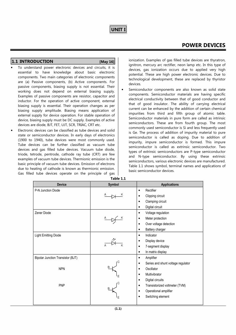
semiconductors, various electronic devices are manufactured.
Table 1.1 shows symbol, terminal names and applications of
basic semiconductor devices.
Table 1.1
Device Symbol Applications
P-N Junction Diode A K
• Rectifier
• Clipping circuit
• Clamping circuit
• Digital circuit
Zener Diode
A K
• Voltage regulation
• Meter protection
• Over voltage detection
• Battery charger
Light Emitting Diode
A K
• Indicator
• Display device
• 7-segment display
• In matrix display
Bipolar Junction Transistor (BJT)
NPN
PNP
B
C
E
B
C
E
• Amplifier
• Series and shunt voltage regulator
• Oscillator
• Multivibrator
• Digital circuits
• Transistorized voltmeter (TVM)
• Operational amplifier
• Switching element

POWER ELECTRONICS (TE E&TC) (1.2) POWER DEVICES
Junction Field Effect Transistor (JFET)
N-channel
P-channel
D
S
D
S
• Amplifier
• Oscillator
• Multivibrator
• Digital circuits
• TVM
• Digital memory
• Switching element
• High power applications
Metal Oxide Semiconductor Field Effect
Transistor (MOSFET)
N-channel
P-channel
D
SG
sub
D
SG
sub
• In power electronics
• Inverter
• Digital circuits
• VLSI ICs
• Amplifier
Uni Junction Transistor (UJT)
E B1
B2
• For triggering of SCR
• Relaxation oscillator
• Time base generator
• Beam deflection circuit of CRO and TV
1.2 INTRODUCTION TO POWER ELECTRONICS
• Power electronics deals with the application of electronic
devices in the control and conversion of electrical power. It is
partly in power engineering and partly in electronics. Power
engineering deals with high electrical power generation,
transmission and utilization at higher frequency. Electronics
deals with low power signal level and data signal. During last
three decades, power electronics achieved phenomenal
growth to occupy an important place in modern technology.
• In broad consideration, electrical engineering field may be
divided into three areas :
(1) Electronics, (2) Power, (3) Control.
• Electrical power generation is a basic need for domestic and
industrial applications. To generate electrical power,
conventional and non-conventional methods are used.
AC electrical power generation and transmission is more
efficient than DC electric power. For power conversion
rectifier, control rectifier, inverter, chopper, cyclo-inverter,
cyclo-converter and other circuits are suitable. Power
electronic equipment involves interaction between the source
and the load. It utilizes small signal electronic control circuits
as well as power semiconductor devices. In early days before
1975, thyratron, ignitron, mercury arc rectifier like gas filled
tubes were used for power conversion and control. Now-a-
days the major component of power electronic circuit is the
thyristor. Thyristor is a fast switching semiconductor and its
function is to modulate the power in AC and DC systems.
• Power electronic circuits are also called as thyristorised
power controllers. The power controllers are generally
classified into five categories.
• Phase Controlled Rectifier : These are also called as AC to
DC converters. For these power controller source is single
phase or three phase. These are used in DC drives,
metallurgical and chemical industries, excitation system for
synchronous system etc.
• Chopper : These are DC to DC converters. It converts fixed
DC input voltage to variable and controllable DC output
voltage. Choppers are commonly used for DC drive, railway
cars, trolley trucks, battery operated vehicles.
• Inverter : These are DC to AC converters. Output may be
variable voltage and variable frequency. Inverters are widely
used in induction motor drive, synchronous motor drive,
induction heating, UPS, HVDC transmission etc.
• Cyclo-Converter : These circuits convert input power at one
frequency to output power at a different frequency. These are
basically used for low speed large AC drive like rotary kiln etc.
• AC Voltage Controller : These converter circuits convert
fixed AC voltage directly to a variable AC voltage at the same
frequency. These are used for lighting control, speed control
of fans, pumps etc.
1.3 APPLICATIONS OF POWER ELECTRONICS
Power electronics is used in various fields such as :
•••• Industrial : For the controlling of AC and DC motors, blowers
and fans; Arc and Industrial furnaces etc.
•••• Residential : Air conditioning, cooking, lighting, refrigeration
door openers, dryers, fans control etc.
G
G

POWER ELECTRONICS (TE E&TC) (1.3) POWER DEVICES
•••• Aerospace : Space shuttle power supplies, satellite power
supplies, aircraft systems.
•••• Commercial : Advertising, heating, air conditioning, central
refrigeration, computer and office equipment, UPS, elevators,
light dimmers and flashers.
•••• Telecommunication : Battery chargers, power supplies
(DC and UPS).
•••• Transportation : Battery charger, traction control of electric
vehicle, electric locomotives, street cars, trolley buses, subway
automotive electronics.
•••• Utility Systems : High Voltage DC Transmission (HVDC),
excitation system, VAR compensation, static circuit breakers,
fan and boiler-feed pumps, supplementary energy systems
(solar, wind).
1.4 MERITS AND DEMERITS OF POWER
ELECTRONIC CONTROLLER
1.4.1 Merits
Power electronic controller converts one form of electrical energy
into another form. This controller uses power devices. Some of
the merits of power electronic systems are as follows :
•••• Flexible control : The output voltage of controller can easily
be controlled by controlling the delay angle.
•••• High efficiency due to low loss in power semiconductor
devices.
•••• The converter reliability is high.
•••• No mechanical movement in converters, so the life of
converter is long and it requires less maintenance.
•••• Dynamic response is faster due to static devices.
•••• Acoustic noise is lower as compared to relays and contactors.
•••• Due to electronic devices used in controller, the size is
compact and of less weight.
1.4.2 Demerits
The demerits of power electronic systems are as follows :
• Harmonics are generated in converters due to switching of
power semiconductor devices. These harmonics are injected
into supply system and load.
• The cost of controller is high.
• The AC to DC and DC to AC converters work at low input
power factors under some conditions. Special measures are
then required for power factor improvements.
1.5 CLASSIFICATION OF POWER ELECTRONIC
CONVERTERS
A power electronic system has various applications. The main use
of power electronics is to control and convert electrical power
from one form to another. Depending upon the input and output,
these power electronic circuits are classified in different ways.
1.5.1 Diode Rectifier
• The output voltage of diode rectifier is fixed DC. It converts
AC into DC. The input voltage may be single phase or three
phase.
• It is a device which converts AC input voltage to a fixed DC
voltage. These rectifiers are used in variety of applications
like battery charging, electrochemical processing, power
supplies etc. following Fig. 1.1 shows the diode rectifier.
Fixed DCO/P
1 or 3A.C. Supply
f f
Rectifier
Fig. 1.1 : Diode rectifier
Classification of Diode Rectifiers :
(a) Half-wave rectifier.
(b) Full-wave rectifier.
(c) Bridge rectifier.
1.5.2 Phase Controlled Rectifier
• This rectifier converts fixed AC input voltage to variable DC
output voltage. The output voltage of phase controlled
rectifier is varied by controlling the delay angle or firing angle
(α). The source voltage (input voltage) is AC, therefore this
rectifier uses line voltage for their commutation, so these are
also called as line commutated or naturally commutated AC
to DC converters.
• These are used in DC drives, metallurgical and chemical
industries etc.
• Fig. 1.2 shows the inputs and outputs of AC to DC converters.
The input is 1φ or 3φ AC. The output is controlled by DC
voltage.
Variavle orfixed DCoutput
1 or 3AC Supply
f f
Firing or delay anglecontrol circuit
Phase controlledrectifier
Fig. 1.2 : Phase controlled rectifier
1.5.3 DC Chopper (DC-to-DC Converter)
• It is a device which converts fixed DC input voltage to a
controllable DC output voltage. The source voltage for this
converter is DC. So this converter requires forced or load
commutation to turn off thyristors. For DC to DC conversion,
power BJT or power MOSFETs are also used and the
converters are called switched mode power supply. DC to DC
converters are used for battery charger, DC drives and DC
power supplies. Fig. 1.3 shows DC chopper.
Fixed or variableDC voltage supply
DCChopper
Fixed DCvoltage supply
Fig. 1.3 : DC chopper

POWER ELECTRONICS (TE E&TC) (1.4) POWER DEVICES
Applications of DC Chopper :
DC chopper (DC to DC) converter is used in :
• Switched-mode power supply (SMPS)
• DC motor control.
• Battery chargers.
1.5.4 Inverters (DC to AC Converter)
• A converter which converts fixed DC voltage to variable AC
voltage. The output may be variable voltage and variable
frequency. The source voltage is DC so for turning OFF the
thyristor, additional circuitry is required, so this converter
uses line, load or forced commutation for turning off the
thyristor. Fig. 1.4 shows the inverter.
VariableAC output voltage
InverterFixedDC input
voltage
Fig. 1.4 : Inverter
• Some of the important applications of inverters are as listed
below :
1. Uninterruptible Power Supply (UPS).
2. Frequency converter.
3. Emergency lighting systems etc.
1.5.5 AC to AC Converter
These converters convert fixed AC input voltage into variable AC
output voltage. These are classified into two types as :
1. AC Voltage Controller (AC Voltage Regulator) :
This converter converts fixed AC voltage directly to a variable AC
voltage at the same frequency. AC voltage controller uses two
SCRs or thyristors in anti-parallel or a TRIAC. Here in this case,
source voltage is AC. Therefore turning off the thyristor, line or
natural commutation is used. Output voltage is controlled by
varying delay or firing angle 'α'.
Main applications of AC voltage regulator are as listed below
(i) Lighting control.
(ii) Speed control of fans and pumps etc.
Fig. 1.5 (a) shows the AC voltage controller.
Variable AC voltagewithout changing frequency
AC voltagecontroller
Fixed ACvoltage supply
Fig. 1.5 (a) : AC voltage controller
2. Cyclo-Converter :
This converter converts input power at one frequency to output
power at a different frequency. In other words, the converter that
converts an AC voltage of fixed amplitude and frequency into an
AC voltage of variable frequency and amplitude is called
cyclo-converter. The word "cyclo" means frequency. So it is also
called as frequency changer or converter. Line commutation is
more commonly used in these converters. These are primarily
used for slow speed large AC drives like rotary kiln etc. Fig. 1.5 (b)
shows inputs and outputs of cyclo-converter.
Variable frequency andvariable voltage AC output
Cyclo-converterFixed
AC supply
voltageand fixed frequency
Fig. 1.5 (b) : Cyclo-converter
1.6 POWER DIODE
• Power semiconductor diode is very similar to low power p-n
junction diodes, called signal diode. The symbol and V-I
characteristics of power diode is very similar to that of a low
power p-n junction diode. Power diode is a uncontrolled
device. The current flows through diode from anode to
cathode only. The diode has two operation modes, one is
forward bias (ON state) and other is reverse bias mode.
Construction of Power Diode :
• A power diode is a two terminal p-n junction device, namely
anode and cathode. It has one p-n junction formed by
alloying, diffusing or epitaxial growth. The modern control
technique in diffusion and epitaxial process permits the
desired device characteristics. Fig. 1.6 (a) and 1.6 (b) show the
sectional view and diode symbol respectively.
+_
+_
A K
V
V
Anode Cathodep n
(a) Sectional view of power diode (b) Symbol of power diode
Fig. 1.6
• The vertically oriented cross-sectional view of power diode is
shown in Fig. 1.6 (c). The vertically oriented structure is
preferred in all the power devices as it increases the more
surface area for the forward current, therefore reduces the
forward resistance and ON-state power dissipation. Anode
Cathode
Junction
Drift layer(Decide the
breakdown voltage)
10 cm19 3-
p
10 cm14 3-
n-
n +
10 cm19 3-
10 mm
w d
250 to 300 mm
Fig. 1.6 (c) : Cross-sectional view of power diode
• The main difference between power diode and low power p-
n junction diode is that a n− layer called drift layer (lightly
doped layer, resistivity of this layer is high) is placed between
p+ (heavily doped) and n
+ layer. Therefore power diode have
larger power, voltage and current handling capacities than
ordinary semiconductor diode.

Power Electronics
Publisher : Nirali Prakashan ISBN : 9789387397217Author : S. D. Sawant, K. P.Akole
Type the URL : http://www.kopykitab.com/product/20828
Get this eBook
60%OFF