a text-book - · pdf filea text-book prepared for 'rne ... the science of gunnery...
TRANSCRIPT
ORDNANCE AND GUNNERY
A TEXT-BOOK
PREPARED FOR 'rnE CADETS OF THE
UNlTED STA'fES MILITARY ACADEMY, WEST POINT
BY
ORMOND M. LISSAK LIEUTENANT-COLONEL, ORDNANCE DEPARTMENT, UNITED STATES ARMY, RETIRED,
L ATE PROFESSOR OF ORDNANCE A N D THE SCIENCE OF GUNNERY
AT THE UNITED STATES MILITARY ACADEMY
FIRST EDITION THIRD THOUSAND
NEW YORK
JOHN WILEY & SONS, INC.
LONDON: CHAPMAN & HALL, LIMITED
1915
iii

Copyright, 190'/'
BY
ORMOND M. LISSAK
THE SCIENTIFIC PRES9
.. OBERT DRUMMOND ANO COMPANyJ
BROOKLYN, N. V.
iv

PREFACE.
THE material of war has undergone greater changes in the past thirty years than in the previous hundreds of years since the introduction of gunpowder. The weapons of attack and defense have become more numerous, more complicated, and vastly more efficient. The appurtenances to their use are more elaborate. The science of gunnery constantly requires of the officer greater know1edge and higher attainments, that he may thoroughly understand the powerful and important instruments that are put under his control and be prepared to obtain from them, in time of need, their full effect.
I have attempted in this text to set before the Cadets of the Military Academy the subjects of Ordnance and Gunnery in such manner as to give to the Cadets a thorough appreciation of the fundamental principles that underlie the construction and effective use of the instruments of wal, and such practical knowledge of the material of today as should be possessed by every army officer.
The purpose held in view in the preparation of thi text has been to present, in order, the theories that apply in the use of explosives and in the construction of Ordnance material, the methods pursued in . the construction of the material, descriptions of the material, and the principles of its use.
The applications of the theoretical deductions to the investigation of the action of gunpowders and other explosives and to the construction and use of Ordnance material, are extensively illustrated by problems fully worked out in the text; the idea being that these solutions, in addition to making evident to the student the practica1 use of the theories, will serve as guides in, solutions of similar problems encountered in practice.
v

vi PREFACE.
When the theoretical deductions are applicable to other than ordnance constructions other problems inserted in the text indicate their more extended field.
In the chapter on interior ballistics, which is taken principally from the wri~ingG of Colonel James M. Ingalls, United States Army, the deduction and application of Colonel Ingalls' latest interior ballistic formulas are fully set forth. The determinations from these formulas have been found in practice to be more closely in accord with the actual results obtained in firings, than determinations from any ballistic formulas hitherto in use.
In the chapter on explosives the theoretical determination of the results from explosions, including the quantity of heat, the volume of the gases, the temperature, the pressure, etc., is explained and illustrated by examples. This · demonstration has not hitherto been available in English.
A simplification has been introduced, by the author of the text, into the gun construction formulas of Clavarino. The simplification materially shortens these extended formulas and reduces the labor required in their application.
The graphic system of representing the pressures and shrinkages in cannon, devised by: Lieut. Commander Louis M. Nulton, -United States Navy, is also explained in connection with the deduction and application of the formulas of gun construction. The graphic system is a material help toward a ready understanding of the subject.
In the subject of exterior ballistics sufficient problems are introduced and fully worked out to illustrate the processes followed in the solutions of the principal problems of gunnery. This course has been adopted with the purpose of removing to a large extent the difficulties usually encountered in the practical appli,cation of the formulas of exterior ballistics.
An appendix to tlw chapter on exterior ballistics contains the deduction of the author's formulas for double interpolation. The formulas are more accurate and more convenient in applicacation than the interpolation formulas previously in use. Explanation of the use of the ballistic tables to which the interpolation formulas apply, follows the deduction of the ,formulas.
The chapter on armor contains information as to the general

PREFACE. Vll
arrangement and thickness of the armor on ships of war, the expected targets of the heavy artillery.
A chapter on submarine mines, torpedos, and submarine torpedo boats concludes the text.
Acknowledgment is due for much assistance obtained from the text-boole on Ordnance and Gunnery, by Captain L. L. Bruff, Ordnance Department, that has been in use at the Military Academy for the past eleven years. The plan of that work has been largely followed, many of its illustrations appear in this volume, and assistance has been derived from its text throughout.
I desire to express my indebtedness to Captain Edward P. O'Hern, Ordnance Department, Principal Assistant in the Department of Ordnance and Gunnery, whose valuable suggestions and helpful criticism have been of marked benefit to the text. Lieutenants Ennis, Bryant, and Selfridge, Artillery Corps, Assistant Instructors of the Department, have also, by their suggestions, added to the value of the text.
I desire, too, to thank Sergeant Carl A. Schopper, of the West Point Ordnance Detachment. The illustrations in the text are the products of his skill as a draftsman, of his knowledge of the illustrative arts, and of his unremitting labor.
ORMOND M. LISSAK. WEST POINT, May 24,.1907.

Blank Page viii of Original

CONTENTS.
CHAPTER 1.
Gunpowders ..
Definitions, 1. History, 2. Charcoal powders, 4. Smokeless powders,5. Guncotton,6. Nitroglycerine small-arm powder, 7. Manufactureof nitrocellulose powder, 9. Other smokeless powders, 10. Proof of powders, 11. Advantages of smokeless powder, 12. Powder charges, 14.- Blank charges, 15.
COMBUSTION OF POWDER UNDER CONSTANT PRESSURE, 16. Constants of form of powder grains, 18. Emission of gas by grains of different forms, 24. Considerations as to best form of grain, 27.
VARIOUS DETERMINATIONS, 28. The number of grains in a pound, 28. The dimensions of irregular grains, 28. Comparison of surfaces, 28. Density of gunpowder, 29.
CHAPTER II.
PAGE
1
Measurement of Velocities and Pressures. . . . . . . . . . . . . . . . . . .. 32
Measurement of velocity, 32. Le Boulengc chronograph, 32. Measurement of very small intervals of time, 40. Schultz chronoscope, 41. Sebert velocimeter, 42. Methods of measuring interior velocities, 43. Measurement of pressures, 44. Initial compression, 45. Small-arm pressure barrel, 45. The micrometer caliper, 46. Dynamic method, of mea.suring pressures, 46. Comparison of the two methods, 47.
CHAPTER III. Interior Ballistics. . . . . . . . . . . . . . . . . . . . . . . . . . . . . . . . . . . . . . .. 49
Scope, 49. Investigations, 49. Gravimetric density of powder, 52. Density of loading, 53. Reduced length of powder chamber, 55. Reduced length of initial air space, 55. Problems, 56.
PROPERTIES OF PERFECT GASES, 57. Mariotte's law, 57. Gay Lussac's law, 58. Characteristic equation of the gaseous state, 58. Problems, 60. Thermal unit, 61. Specific heat, 62. Relations between heat and work in the expansion of gases, 63. Isothermal expansion, 65. Adiabatic expansion, 65.
NOBLE AND ABEL's EXPERIMENTS, 67. Apparatus, 67. Results of the experiments, 68. Relation between pressure and density of load
ix

x CONTENTS.
ing, 69. Temperature of explosion, 70. Relations between volume and pressure in the gun, 71. Theoretical work of gunpowder, 73.
FORMULAS FOR VELOCITIES AND PRESSURES IN THE GUN, 74. Principle of the covolume, 75. Differential equation of the motion of a projectile in a gun, 76. Dissociation of gases, 78. Ingall's formulas, 79. Combustion under variable pressure, 82. Velocity of the proj'ectile while the powder is burning, 85. Velocity after the powder is burned, 85. Pressures, 87. Values of the constants in the equations, 90. The force coefficient, 93. Values of the X functions, 94. Interpolation, using second differences, 95. Characteristics of' a powder, 97.
ApPLICATION OF THE FORMULAS, 97. DETERMINATIONS FROM MEASURED INTERIOR WELOCITIES, 102. Prob
lem 1, 102. Problem 2, 113. The action of different powders, 117. Quick and slow powders, 120. Effects of the powder on the design of a gun, 121.
DETERMINATIONS FROM A MEASURED MUZZLE VELOCITY AND MAXIMUM PRESSURE, 122. Problem 3, 122. The force coefficient, 131. Prob-lem 4, 132. '
TABLE OF UNITED STATES ARMY CANNON, 135.
CHAPTER IV.
Explosives . . .............................. ' ........ '. . . . .. 136
Effects of explosion, 136. Orders of explosion, 137. Vielle's classification of nitrocelluloses, 138. Conditions that influence explosion, 139. Uses of different explosives, 140. Bursting charges in projec~ tiles, 141. Exploders, 143. Explosion by influence, 144.
THEORETICAL DETERMINATION OF THE RESULTS FROM EXPLOSIONS, 145. Specific heats of gases, 145. Specific volumes of gases, 146. Classification of gases, 147. Quantity of heat, 1:'17. Heats of formation, 148. Quantity of heat at constant pressure, 149. Quantity of heat at constant volume, 151. Potential, 154. Volume of gases, 154. Temperature of explosion, 155. Pressure in a closed chamber, 157. Complete calculation of the effects of explosion, 161.
CHAPTER V.
Metals Used in Ordnance Construction . ................... " 163
Stress' and strain, 163. Physical qualities of metals, 163. Strength of metals, 164. Testing machine, 166. Copper, brass, bronze, 167. Iron and steel, 167. Hardening and tempering steel, 169. Annealing, 174. Uses, 175. Gun steel, 175.
MANUFACTURE OF STEEL FORGINGS FOR GUNS, 176. Open hearth process, 176. Other processes, 180. Casting, 180. Defects in ingots, 181. Whitworth's process of fluid compression, 181. Processes after casting, 183. Strength of parts of the gun, 187.

CONTENTS.
CHAPTER VI.
Guns ...
ELASTIC STRENGTH OF GUNS, 188. The elasticity of metals, 188. Hooke's law, 188. Equations of relation between stress 'and strain, 190. Problems, 190. Stresses and strains in a closeQ cylinder, 191. Lame's laws, 192. Basic principle of gun construction, 195. Simplification of the formulas of gun construction, 196. Stresses in a simple cylinder, 198. Limiting interior pressures, 202. Graphic representation, 204. ' Limiting exterior pressure, 205. Thickness of cylinder, 206. Longitudinal strength, 206. Problems, 207. Compound cylinder, Built-up guns, 208. System composed of two cylinders, 209. Application of formulas to outer cylinders, 210. System in action, 212. System at rest, 213. Graphic representation,' 215. Shrinkage, 217. Radial compression of the tube, 219. Prescribed shrinkage, 220. Application of the formulas, 220. Problems, 222. Curves of stress in section, 227. Systems composed of three and four cylinders, 229. Minimum number of cylinders for maximum resistance, 230. Graphic construction, three cylinders, 230. Wire wound guns, 234. '
CONSTRUCTION OF GUNS, 236. General characteristics, 236. Operations in manufacture, 239. Gun lathe, 240. Boring and turning mill, 241. Assembling, 242. Rifling the bore, 244.
MEASUREMENTS,245. Necessity of accurate measurements, 245. Vernier caliper, 245. Measuring points, 246. The star gage, 247. Calipers, 248. Standard comparator, 249.
RIFLING, 250. Twist, 250. Increasing twist, 251. Equation of the developed curve of the rifling, 251. ,Problems, 252. Service rifling, 254.
BREECH MECHANISM, 255. General, characteristics, 255. Slotted screw breech mechanism, 256. Bofors breech mechanism, 258. The Welin breech block, 259. Obturation, 260. The De Bange obturator, 260. The Freyre obturator, 262. Firing mechanism, 263. Sliding wedge breech mechanism, 265. Older forms of breech mechanism, 266. 12-inch mortar breech mechanism, 268. Automatic and semi-automatic breech mechanisms, 269.
CHAPTER VII.
Recoil and Recoil Brakes ... .' . , ,
Stresses on the gun carriage, 274. Velocity of free recoil, 274. Determination of the circumstances of free recoil, 276. Retarded recoil, 279. Recoil brakes, 280. Hydraulic brake with variable orifice, 281. Total resistance to recoil, 281. Values of the total and partial resistances, and velocities of recoil, 283. Resistance of the hydraulic brake, Pressure in the cylinder, 286. Relation between the pressure, area of orifice, and velocity of recoil, 286. Brake with variable pressure, 288. Constant pressure, 288. Brake with con-
xi
188
274

xii CONTENTS.
stant pressure, 289. Profile of the throttling bar, 290. Neglected resistances, 291. Recoil system of seacoast carriages, 291. Modification of recoil system, 293. Wheeled carriages, Recoil, 294. Design of a field carriage, ~OO. 3-inch field carriage recoil system, 301. Recoil system of other carriages, 303.
CHAPTER VIII.
Artillery of the United States Land Service . . . ............... 304
Mobile artillery, 304. Advantages of recent carriages, 306. The mountain gun, 307. Field artillery, 310. The 3-inch field gun, 311. Field howitzers and mortars, 319. Siege artillery, 320. The 4.7-inch siege gun, 321. The 6-inch siege howitzer, 324. Siege artillery in present service, 330. Seacoast artillery, 332. Seacoast guns, 333. Seacoast gun mounts, 333. Pedestal mounts, 335. The balanced pillar mount, 337. Barbet.te carriages for the larger guns, 339. Disappearing carriages, 341. 12-inch disappearing carriage, model 1901, 342. Modification of the recoil system, 346.6-inch experimental disappearing carriage, model 1905, 346. Seacoast mortars, 349. The 12-inch mortar carriage, model 1896, 350. The 12-inch mortar carriage, model 1891, 352. Subcaliber tubes, 353. Drill cartridges, projectiles, and powder charges, 355.
CHAPTER IX.
Exterior Ballistics . .
Definitions, 357. The motion of an oblong projectile, 358. Determination of the resistance of the · air, 360. Mayevski's formulas for resistance of the air, 362. Trajectory in air, Ballistic formulas, 363. The balhstic coefficient, 367. The functions, 368. Formulas for the whole range, 370. The ballistic elements, 371. The rigidity of the trajectory, 371. Secondal'Y functions, 372. Ballistic tables, 315. Exterior ballistic formulas, 376. Interpolat.ion in Table II, Double interpolation formulas, 378. The solution of problems, 380. Problems, 381. Correction for altitude, 383. The effect of wind, 387. The danger space, 392. Method of double position, 393. The danger range, 396. Curved fire, 398. High angle fire, 401. Calculation of the coefficient of reduction, 410. Perforation of armor, 411. Range tables, 412. Curvature of the earth, 413.
ACCURACY AND PROBABILITY OF FIRE, 413. Accuracy, 413. Probability of fire, 415. Probability curve, 417. Probable zones and rectangles, 420. Probability of hitting any area, 420.
357
A'PENDIX. THE USE OF TABLE II, INGALL'S BALLISTIC TABLES .. . .. . .. 421 Description of Table II, 421. Deduction of formulas for double inter
polation, 422. Double interpolation formulas, ·425. Double interpolat.ion in simple tables, 426. Use of the formulas, 427.

CONTENTS. xiii
CHAPTER X.
Projectiles . .
Old forms of projectiles, 438. Modern projectiles, 440. Form of projectile, 442. Canister, 443. Shrapnel, 444. The bursting of shrapnel, 446. Shot and shell, 448. Armor piercing projectiles, 449. Action of the cap, 451. Deck piercing and torpedo shell, 454. Latest form of base of shell, 454. Shell tracers, 454. Hand grenades, 455. Volumes of ogival projectiles, 455. Weights of projectiles, 456. Thickness of walls, 456. Sectional density of projectiles, 458.
MANUFACTURE OF PROJECTILES, 460. Cast projectiles, 460. Chilled projectiles, 461. Forged projectiles, 461. Requirements in manufacture, 462. Inspection of projectiles, 462. Ballistic tests, 464. The painting of projectiles, 464.
CHAPTER XI.
Armor. ..... ..... ........... . ... . .... . ................. . History,466. Harvey and Krupp armor, 467. Manufacture of armor,
467. Armor bolts, 469. Ballistic test of armor, 471. Characteristic perforations, 471. Armor protection of ships, 472. Chilled cast-iron armor, 475. Gun shields, 475. Field gun shields, 476.
CHAPTER XII.
438
461>
Primers and Fuses for Cannon. . . . . . . . . . . . . . . . . . . . . . . . . . . .. 47':
Common friction primer, 477. The service combination primer, 478. Other friction and electric primers, 481. Percussion primers, 481. 20-grain saluting primer, 483. nO-grain electric primer, 484. Combination electric and percussion primer, 484. Igniting primers, 484. Insertion of primers in cartridge cases, 485.
FUSES, 486. Percussion fuse, 486. Point percussion fuse, 487. Base . percussion fuses, 489. Combination time and percussion fuses, 492.
Service combination fuse, 492. Combination fuse, old pattern, 49S. Ehrhardt combination fuse, 497. Detonating fuses, 498. The fuse setter, 499. Arming resistance of fuse plungers, SOL Problems, 501.
CHAPTER XIII.
Sights .. .. .. .... . ........ . ............. . ................ SOl
Principle and methods, 505. Graduation of rear sights, S06. Correction for drift, S07. Correction for inclination of site, S07. Sights for mobile artille'ry, 509. The adjustable or tangent sight, 509. The panoramic sight, S12. The range quadrant, 514. 'Telescopic sights, S17. Telescopic sight, model 1904, 517. Telescopic sight, model 1898, 520. The power and field of view of telescopes, 522. Aiming
. mortars, 522. The gunner's quadrant, 523.

xiv CONTENTS.
CHAPTER XIV.
Range and Position Finding. . . ., . . . . . . . . . . . . . . . . . . . . . . . .. 525
Range finders, 525. Depression range finders, 526. Swasey depression range and position finder, 526. The plotting room, 527. Field range and position finding, 528. The Weldon range finder, 528. The battery commander's telescope, 531. The battery commander's ruler, 532. Plotting board for mobile artillery, 537. Other range finders, 538. The Berdan range finder, 538. The Barr and Stroud range finder, 538. The Le Boulenge telemeter, 540.
CHAPTER XV.
Small Arms and their Ammunition. . . . . . . . . . . . . . . . . . . . . . .. 541
Service small arms, 541. The 38-caliber revolver, 541. The Colt automatic pistol, 544. Modern military rifles, 546. Requirements, 547. Life of the rifle. Erosion, 549. The U. S. magazine rifle, model 1903, 550. Appendages, 554. Deviation. Drift, 555. The 22-caliber gallery practice rifle, 556.
AMMUNITION FOR THE 30-CALIBER MAGAZINE RIFLE, 556. The ball cartridge, 556. Bullets, 559. The Blank cartridge, 560. The dummy cartridge, 561. The guard cartridge, 561. Proof of ammunition, 562.
CHAPTER XVI.
Machine Guns . ..
Service machine guns, 564. The Gatling machine gun, 565. The Maxim automatic machine gun, 569. The Maxim one-pounder automatic gun, 574. The Colt automatic machine gun, 575.
CHAPTER XVII.
564
Submarine Mines and Torpedoes. Submarine Torpedo Boats.. 576
SUBMARINE MINES AND TORPEDOES, 576. History, 576. Confederate mines, 578. Spanish mechanical mine, 580. Electric mines, 581. Buoyant mines, 581. Ground mines, 582. The explosive, 582. The charge, 583. Defensive mine systems, 583. Countermining, 585. The removal of mines, 585. Mobile and automobile torpedoes, 586. The Sims-Edison torpedo, 586. The Whitehead torpedo, 586. The Bliss-Leavitt torpedo, 588. The Howell torpedo, 589.
SUBMARINE TORPEDO BOATS, 590. The Holland submarine torpedo boat, 591. The Lake submarine torpedo boat, 592.

TABLES.
Table I. LOGARITHMS OF THE X FUNCTIONS......................... 596
Table II. HEATS OF FORMATION OF SUBSTANCES .•. ..... .. . ... . ..•. . .. 599
Table III. SPECIFIC HEATS OF SUBSTANCES ......•.................... 601
Table IV. DENSITIES AND MOLECULAR VOLUMES OF SUBSTANCES .•... . .. 602
Table V. ATOMIC WEIGHTS' ....... , ..... , . .. , .. . ....... , .... , ' .... '. 603
Table VI. CONVERSION; METRIC AND ENGLISH UNITS, TEMPERATURES .. 604
xv
v

~.
BREECH.
r BREECHI rr BLOCKill
B A2""
TUBE.
CHASE. CI
ptE;] CHA+E. ~~ROJEcny RlrLED BORE.
~
lill 12-INCH RIFLE, MODEL OF 1900, 40 CALIBERS, 59.10 TONS.
(Diameters Exagli:erated.)
MUZZLE.

ORDNANOE AND GUNNERY.
CHAPTER 1.
GUNPOWDERS.
I. Definitions.-Explosion, in a general sense, may be defined as a sudden and violent increase in the volume of a substance. In a chemical sense, explosion is the extremely rapid conversion of a solid or a liquid to the gaseous state, or the instantaneous" combination of two or more gases accompanied by increase of volume. Chemical explosion is always accompanied by great heat.
An explosion due to physical causes alone, as when a gas under compression is suddenly released and allowed to expand, causes cold.
The explosion of gunpowder may be divided into three parts: ignition, inflammation, and combustion.
Ignition is the setting on fire of a part of the grain or charge. Gunpowder is ignited by heat, which may be produced by
electricity, by contact with an ignited body, by friction, shock, or by chemical reagents.
An ordinary flame, owing to its slight density, will not ignite powder readily. The time necessary for ignition will vary with the condition of the powder. Thus damp powder ignites less easily than dry; a smooth grain less easily than a rough one; a dense grain less easily than a light one.

2 ORDNANCE AND GUNNERY.
Powder charges in guns are ignited by primers, which are fired by electricity, by friction, or by percussion.
Inflammation is the spread of the ignition from point to point . of the grain, or from grain to grain of the charge.
With small grain powders the spaces between the grains are small, and the time of inflammation is large as compared with the time of combustion of a grain; but with mo.dern large grain powders the facilities for the spread of ignition and the time of burning of the grain are so great that the whole charge is supposed to be inflamed at the same instant, and the time of inflammation is not considered.
Combustion is the burning of the inflamed grain from the surface of ignition inward or outward or both, according to the form of the grain.
Experiment shows that powder burns in the air according to the following laws;
1, In parallel layers, with uniform velocity, the velocity being ind~pendent of the cross section burning.
2. 'J'he velocity of combustion varies inversely with the density <;>f the powder.
When a charge of powder is ignited in a gun inflammation of the whole charge is rapidly completed. The gases evolved from the burning . grains accumulate behind the projectile until the pressure they exert is sufficient to overcome the resistance of the projectile to motion, The accumulated gases, augmented by those formed by the continued burning of the charge, expand into the space left behind the projectile as it moves through the bore, exerting a continual pressure on the projectile and increasing its velocity until it leaves the muzzle.
History.-The Chinese are said to have employed an explosive mixture, very similar to gunpowder, in rockets and other pyrotechny as early as the seventh century.
The earliest record of the use in actual war of the mixture of charcoal, niter, and sulphur called gunpowder, dates bitck to the fourteenth century. Its use in war became general at the begin-

GUNPOWDERS. 3
ning of the sixteenth century. Until the end of the sixteenth century it was used in the form of fine powder or dust. To overcome the difficulty experienced in loading small arms from the muzzle with powder in this form, the powder was at the end of the sixteenth century given a granular form. With the same end in view attempts at breech loading were made; but without success, as no effective gas check, which would prevent the escape of the powder gases to the rear, was devised.
No marked improvement was made in gunpowder until 1860, when General Rodman, of the Ordnance Department, U. S. Army, discovered the principle of progressive combustion of powder, and that the rate of combustion, and consequently the pressure exerted in the gun, could be controlled by compressing the fine grained powder previously used into larger grains of greater density_ The rate or velocity of combustion was found to diminish as the density of the powder increased. The increase in size of grain diminished the surface inflamed, and the increased density diminished the rate of combustion, so that, in the new form, the powder evolved less gas in the first instants of combustion, and the evolution of gas continued as the projectile moved through
: the bore. By these means higher muzzle velocities were attained with lower maximum pressures. To obtain a progressively increasing surface of combustion General Rodman proposed the perforated grain, and the prismatic form as the most convenient for building into charges. As a result of his investigations powder was thereafter made in grains of size suitable to the gun for which intended, small grained powder for guns of small caliber, and large grained powder for the larger guns. The powders of regular granulation, such as the- cubical, hexagonal, and sphero-hexagonal, came into use, and finally for larger guns the prismatic powder in the form of perforated hexagonal prisms.
A further control of the velocity of combustion of powder . was obtained in 1880 by the substitution of an underburnt charcoal for the black charcoal previously used. The reSUlting powder, called brown or cocoa powder from its appearance, burned more

4 ORDNANCE AND GUNNERY.
slowly than tlle black powder, and wholly replaced that powder in the larger guns.
,A still further advance in the improvement of powder was brought about in 1886 by the introduction of smokeless powders. These powders are chemical compounds, and not mechanical mixtures like the charcoal powders; they burn more slowly than the
Hexagonal.
Sphero-hengonal. Prismatic.
charcoal powders, and produce practically no smoke. Smokeless powders have now almost wholly replaced black and brown powders for charges in guns. Black powder is used in fuses, primers, and igniters, in saluting, charges, and as hexagonal powder m the smaller charges for seacoast mortars.
2. Charcoal Powders.-CoMPOSITION.-Black gunpowder is a mechanical mixture 'of niter, charcoal, and sulphur, in the proportions of 75 parts niter, 15 charcoal, and 10 sulphur.
The niter furnishes the oxygen to burn the charcoal and sulphur. The charcoal furnishes the carbon, and the sulphur gives density to the grain and lowers its point of ignition.
The distinguishing characteristic 'of charcoal is its color, being brown when prepared at a temperature up to 280°, from this to 340° red, and beyond 340° black.
Brown powder contains a larger percentage of niter than black powder, and a smaller percentage of sulphur. A small percentage of some carbohydrate, sucn as sugar, is also added. Its color is du,e to the underburnt charcoal.

GUNPOWDERS.
MANUFACTURE.-The ingredients, purified and finely pulverized, are intimately mixed in a wheel mill under heavy iron rollers. The mixture is next subjected to high pressure in a hydraulic press. The cake from the press is broken up into grains by rollers, and the grains are rumbled in wooden barrels to glaze and give uniform density to their surfaces. The powder is then dried in a current of. warm dry air, and the dust removed. The powder is thoroughly blended to overcome as far as possible irregularities in manufacture.
For powders of regular granulation the mixture from the wheel mill was broken up and pressed between die plates constructed to give the desired shape to the grains. Prismatic powder was made by reducing the mill cake to powder and pressing it into the required form.
Smokeless Powders.-There are two classes of smokeless powders used in our service: nitroglycerine powder in small arms, and nitrocellulose powder in cannon. They are both made from guncotton, to which is added for the small-arm powd6 about 30 per cent by weight of nitroglycerine.
COMPARISON OF NITROGLYCERINE AND NITROCELLULOSE PowDERs.-The temperature of explosion of nitroglycerine powder is higher than that of nitrocellulose powder. As the erosion of the metal of the bore of the gun is found to increase with the temperature of the gases, greater erosion follows the use of nitroglycerine powder. The endurance, or life, of a modern gun is dependent on the condition of the bore, and on account of the great cost of cannon erosion becomes a more serious defect in cannon than in small arms. On this account, therefore, nitrocellulose powder is more suitable than nitroglycerine powder for cannon.
To produce a given velocity a larger charge of nitrocellulose than of nitroglycerine powder is required. This necessitates for nitrocellulose powder a larger chamber in the gun, and the increase in size of the chamber involves in0reased weight of metal in the gun. This is more objectionable in a small arm than in cannon,

6 ORDNANCE AND GUNNERY •
. for the increased weight of the gun and of the charge adds to the burden of the soldier. For this reason nitroglycerine powder is more suitable than nitrocellulose powder in the small arm;
In the manufacture of nitroglycerine powders for cannon, a satisfactory degree of stability under all the conditions to which cannon powders are exposed was not obtained. In time the powder deteriorated, and exudation of free nitroglycerine occurred. Detonations and the bursting of guns followed. In the small-arm cartridge the powder is hermetically sealed, and as now manufactured appears to possess a satisfactory degree of stability.
For these reasons nitroglycerine powder has been selected for use in small . arms in our service, and nitrocellulose powder for use in cannon.
A disadvantage attending the use of nitrocellulose powder arises from the fact that in the explosion there is not a sufficient amount of oxygen liberated to combine with the carbon and form CO2• The reaction on explosion is approximately represented by the following equation.
A large quantity of CO, an inflammable gas, is often left in the bore. On opening the breech more oxygen is admitted with the air, and should a spark be present the co' burna violently, uniting with the oxygen and forming CO2• This burning of the gas . is called a flareback. An instance of it has occurred with disastrous results in a turret gun aboard one of our men-of-war, the Missouri.
3. Guncotton.-Guncotton forms the base of most smokeless powders. When dry cotton, C6H100S, is immersed in a mixture of nitric and sulphuric acids part of the hydrogen of the cotton is replaced by N02 from the nitric acid. The sulphuric acid ~akes up the water formed · during the reaction and prevents the dilution of the nitric acid. The nitrated cotton,
GUNPOWDERS. 7
or nitrocellulose, may be of several orders of nitration; depending on the strength and proportions of the acids, and the temperature and duration of immersion; as mononitrocellulosc, dinitrocellulose, trinitrocellulose, according as one or more atoms of hydrogen are replaced. All nitrocellulose is explosive, and the order of explosion produced is higher as the nitration is higher. Dinitrocellulose and trinitrocellulose are used in the manufacture of smokeless powders. . The lower orders of nitrocellulose, containing less than 12.75 pel' cent of nitrogen, are soluble in a mixture of alcohol and ether. Trinit:cocellulose contains a higher percentage of nitrogen, and is insoluble in alcohol and ether but soluble in acetone.
MANUFACTURE OF GUNCOTTON FOR SMOKELESS POWDERS.
The process followed is practically the same for all varieties, the nitration being stopped at the point desired in each case.
The cotton used is the waste or clippings from cotton mills. It is first finely divided and then freed from grease, dirt, and other impurities by boiling with caustic soda. After cleansing it i3 passed through a centrifugal wringer and then further dried in a dry-house.
The dry cotton is immersed in a mixture of about three parts sulphuric acid and two parts nitric acid for about fifteen minutes; after which the cotton is run through a wringer to remove as much acid as possible. It is then thoroughly washed or drowned.
After this washing the guncotton is reduced to a pulp and further washed to remove any trace of acid which may have been freed in pulping, carbonate of soda being added to neutralize the acid.
The water is then partially removed from the pulp by hydraulic pressure, and the dehydration is completed by forcing alcohol under high pressure through the compressed cake.
4. Nitroglycerine Small-arm Powder.-Lafiin and Rand, W. A.-In the manufacture of this powder highly nitrated gun- . cotton called insoluble nitrocellulose is used. It is insoluble in ether and alcohol but sohlble in acetone.

8 ORDNANCE AND GUNNERY.
The powder is composed of
Insoluble nitrocellulose ........... . Nitroglycerine ................... . Metallic salts. . . . . . . . . . . . . . . . . ... .
67.25 per cent 30.00 per cent 2.75 per cent
Forty pounds of acetone serve as solvent for 100 pounds of the above mixture.
The nitroglycerine and acetone are first mixed. The acetone makes the nitroglycerine less sensitive to pressure or shock, and therefore less dangerous to handle in the subsequent operations. The dried guncotton is spread in a large copper pan, the finely ground metallic salts are sifted over it, and the mixed nitroglycerine and acetone are sprinkled over both. The whole is mixed by hand by means of a wooden rake for a period of about ten minutes, the object of the mixing being to thoroughly moisten the guncotton for the purpose of eliminating the danger from the presence of dry guncotton in the next operation. The mixed mass is put into a mixing machine, where it is mechanically mixed for a period of three hours. It comes from the mixing machine in the form of a colloid or jelly like paste. It is then stuffed and compressed into brass cylinders, from which it is forced by hydraulic pressure through dies fitted with mandrels. It comes from the die in the form of a long hollow string or tube, and is received on a belt which carries it over steam pipes into baskets. The drying which it receives while on the belt strengthens the tube, and after remaining half an hour in the baskets it becomes sufficiently tough to be cut into grains. This is done in a machine provided with revolving knives. The resulting grains' are beadshaped single perforated cylinders and have a length of about one twentieth of an inch. The powder is dried for two or three weeks at a temperature not to exceed 110° F. It is then thoroughly mixed twice in the blending barrels and graphited at the same time. It is carefully screened to remove large grains, dust. and foreign matter, and is packed in muslin bags in metallic barrels holding 100 pounds.
GUNPOWDERS. . 9
Cordite.-This is an English nitroglycerine powder, composed of 58 per cent of nitroglycerine, 37 per cent of guncotton, and 5 per cent of vaseline. The vaseline serves to render the powder water proof and improves its keeping qualities. For small arms the powder is made in the form of slender cylindrical rods, the length of the chamber of cartridge. For cannon it is in thicker and longer rods, in tubular form, or in the form of perforated cylinders. For heavy guns ' a powder called Cordite M. D. has lately been introduced. The composition (30 parts nitroglycerine, 65 parts guncotton, 5 parts vaseline) is very similar to that of our small-arm powder. The reduction in the percentage of nitroglycerine was made for the purpose of lowering the temperature of explosion and reducing the erosion in the bore.
Wetteren Powder.-A nitroglycerine powder manufactured at the Royal Belgian Factory at Wetteren. The solvent used is amyl acetate.
5. Manufacture of Nitrocellulose Powder.-The guncotton f'
used contains 12.65 per cent of nitrogen, and is soluble in the ether-alcohol mixture. I t is prepared as previously described, the dehydration With alcohol being so conducteq that when completed the proper proportion of alcohol for solution remains in the cake. The guncotton cake is broken up and ground until it is free from lumps, and is then placed in a mixing machine
' with the proper amount of ether, two parts of ether to one of alcohol. During the mixing the temperature is kept at 5° C. to prevent loss of the solvent.
The powder comes from the mixing machine as a colloid, and the remaining processes are similar to those described for nitroglycerine powder.
After graining, the solvent is recovered by forcing heated air over the powder. The ether and alcohol vapors are collected and afterwards condensed for further use. The powder is dried for a period varying from six weeks to three. months, depending on the size of the grain. The drying is never complete, a small

10 ORDNANCE AND GUNNERY.
percentage of the solvent always remaining, but care is taken that the remaining percentage shall be uniform.
In the · manufacture of all powders uniformity in the product can only be obtained by the strictest uniformity in the quantities and quality of the substances used, and in the conduct of the various processes.
Cannon powders are, as a rule, not graphited. Other Smokeless Powders.-The length of time required
for the drying of nitrocellulose powders has led to the development of other powders that require little or no time to dry.
Two such powders have been tested. One, stabilite, is composed of nitrocellulose with or without nitroglycerine and a solvent that is itself an explosive and not volatile. The other is similar to the present nitrocellulose powders except that dinitrocellulose is used in its manufacture instead of trinitrocellulose.
To make up for the insufficiency of oxygen in nitrocellulose, already referred to, a number of smokeless powders are made by a combination of nitrocellulose with nitroglycerine or with the nitrates of barium, potassium, and sodium. The nitroglycerine or the metallic nitrates furnish the oxygen which is deficient in the nitrocellu.lose.
E. C. Powder.-This powder contains both soluble and insoluble nitrocellulose and the nitrates of barium, potassium, and sodium. It is yellow in color and of nne granulation. It is an easily ignited quick burning powder and is used in our service in blank small-arm cartridges.
Schultze Powder, the type of smokeless sporting powders, is of constitution similar to that of E. C. powder.
Troisdorf Powder, used in the German service, and B. N. Pow- . der, in the French service, are other powders similarly constituted. All these powders differ principally in the proportion of the ingredients, and also in the organic substance used as a cementing agent.
Maxim Powder is composed of nitrocellulose, both soluble and insoluble, nitroglycerine, and a small percentage of sodium carbonate.
GUNPOWDERS. 11
Form and Size of Grain.~For most cannon in our service the powder is formed into a cylindrical grain with seven longitudinal perforations, one central and the other six equally distributed midway between the center of the grain and its circumference. A uniform thickness of web is thus obtained. The powder is of a brown color and has somewhat the appearance of horn. The length and diameter of the grain vary in powders for different guns, the size of grain increasing with the caliber of the gun. For the 3-inch rifle the grain has a length of about i of an inch and a diameter of -(~ of an inch. For the 12-inch rifle the length .is 1 t inches and the diameter i of an inch. For some of the smaller guns the grains are in the form of thin flat squares.
In other services cannon powders are made into grains of various shapes. -Cubes, solid and tubular rods of circular cross section, flat strips, and rolled sheets are among the forms that have been used.
6. Proof of Powders.-All powders used by the Army are r furnished by private manufacturers. The materials and processes employed in the manufacture are prescribed by the Ordnance Department in rigid specifications, and the manufacture in all its stages is under the inspection of the Department. The proof of the powder consists of tests made to determine its ballistic qualities, its uniformity, and its stability under various conditions. Its ballistic qualities and uniformity are determined from proof firings made in the gun for which the powder is intended. The required velocity must be obtained without exceeding the maximum pressure specified. The mean variation in velocity
\
ina number of rounds must not exceed, in the small arm 12 feet per second, in cannon 1 per cent of the required velocity.
The stability of the powder under various conditions is determined by heat tests, and by a number of special tests. For small,;, arms powder the heat test consists in subjecting the powder, pulverized, to a temperature of 1500 to 1540 F. for 40 minutes. It must not in that time emit acid -vapors, as indicated by the
12 ORDNANCE AND GUNNERY.
slightest discoloration of a piece of iodide of potassium starch paper partially moistened with dilute glycerine. The other tests consist in exposing the powder both loose and loaded in cartridges, to heat, cold, and moisture, for periods varying from six hours to one week. When fired the variations in velocities and pressures must not exceed specified limits.
Nitrocellulose cannon powders are subjected to a heat of 1350 C. (2750 F.) for five hours. Acid fumes, as indicated by the reddening of blue litmus paper, must not appear under exposure of an hour and a quarter, nor red nitrous fumes under two hours. Explosion must not occur under five hours. Other test8 are made for the determination of the loss of weight when subjected to heat, of the moisture and volatile matter in the powder, of the quantities of nitrogen in the powder, and of ash in the cellulose.
For the proper regulation of the evolution of gas in the gun it is important that the grains of smokeless powder retain their general shape while burning. If they break into pieces under the pressure to which they are subjected, the inflamed surface is increased, gas is more quickly evolved, and the pressure in the gun is raised. The powder is therefore subjected to a physical test to determine that the grain has sufficient strength and toughness. The grains are cut so that the length equals the diameter, and are then subjected to slow pressure in a press. The grain must shorten 35 per cent of its length before cracking.
Powder grains incompletely burned, that have been recovered after firing, show that the burning proceeds accurately in parallel layers. The outer diameter of the grain is reduced and the diameter of the perforations increased in exactly equal amounts.
7. Advantages of Smokeless Powder.-The advantages obtained by the use of smokeless powder are due almost wholly to the fact that the powder is practically completely converted into gas. The experiments of Noble and Abel show that the gases evolved by charcoal powders amount to only 43 per cent of the weight of the powder, and part of the energy of this quan-
GUNPOWDERS. 13
tity of gas is expended in expelling the residue from the bore. A smaller quantity of smokeless powder will therefore produce an equal weight of gas, and with smaller charges we may give to the projectile equal or higher velocities. The smokelessness of the powder and the absence of fouling in the bore are also due to the complete conversion of the powder into gas.
Ignition and Inflammation of Smokeless Powder.-Though the temperature at which smokeless powder ignites, about 1800
C., is much lower than that required for the ignition of black powder, 3000 C., the complete inflammation of a charge composed only of smokeless powder takes place more slowly than the inflammation of a charge of black powder. This is due to the slower burning of the smokeless powder and the consequent delay in the evolution of a sufficient quantity of the heated gas to completely envelop the grains composing the charge. In the long chamber of a gun the gases first evolved at the rear of the charge may, in expanding, acquire a considerable velocity. The pressure due to their energy is added to the static pressure due v
to their temperature and volume, thus increasing the total pressure in the gun. The movement of the gases back and forth causes what are called wave pressures, and if the complete ignition of the charge is delayed until the projectile has moved some distance down the bore, there may result at some point in the gun a higher pressure than the metal of the gun at that point can resist.
For this reason and in order to insure the practically ins tan:" taneous ignition of the whole charge, small charges of black powder are added to every smokeless powder charge. The priming charges of black powder insure against hang-fires and misfires, and by producing uniformity of inflammation assist toward uniformity in the ballistic results.
In addition, in order to prevent as far as possible the production of wave pressures, the charge of powder, whatever its weight, is given when practicable a length equal to the length of the chamber.
14 ORDNANCE AND GUNNERY.
8~ Powder Charges.-The powder for a charge in the gun is inserted in one or more bags, depending upon the weight of the charge. The bags are made of special raw silk and are sewed with silk thread. The ends of each bag are double, and between the two pieces at each end is placed a priming charge of black powder, quilted in in squares of about two inches and uniformly spread over the surface.
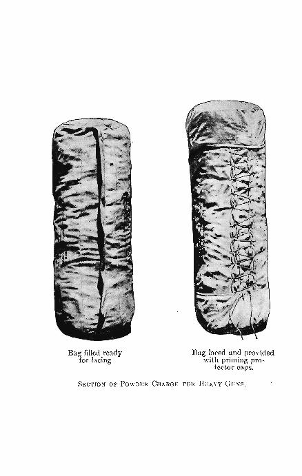
The charge is inserted through an unsewed seam at one end, and the seam is then sewed. The bag, purposely made large, is then drawn tight around the charge by lacing drawn with a needle between two pleats on the exterior. Two priming protector caps are then drawn over the ends of the bag and fastened by draw strings. In the bottom of each cap is a disk of felt which serves to keep moisture from the priming charge and prevents the loss of the priming through wearing of the bottom of the bag. For convenience in handling the charge a cloth strap is attached to each protector cap. By means of the straps the protector caps may be pulled off without undoing the draw strings when the charge is to be inserted in the gun.
The mustr~tions show a bag filled ready for . lacing, and a bag filled and laced and provided with the priming protector caps.
The weight of each portion of the charge should not be greater than can be readily carried by one man. Thus the charge of 360 pounds for the 12-inch rifle is put up in four bags each holding 90 pounds.
As previously stated, the charge whatever its weight is made up if practicable of a length nearly equal to that of the chamber, with a minimum limit of nine tenths of that length.
Raw silk does not readily hold fire. With powder bags made of cotton cloth it occasionally happens that a fragment of the bag remains burning in the bore, and to this fact is ascribed the flarebacks that have occurred. Powder bags treated with chemicals to render them non-inflammable have also been tried. Ammonium phosphate is found to be the best agent for this purpose.
Bag filled ready for lacing
Bag laced and provided wi th priming pro
tector caps.
Page 14b

GUNPOWDERS. 15
A nitrocellulose cloth which will burn up completely and leave no residue has been used as a material for powder bags, but as the charge. of powder enclosed in this material is much more subject to accidental ignition by a chance spark, the nitrocellulose cloth is not generally adopted.
The powder charge in fixed ammunition is placed loose in the cartridge caSe.
In fixed ammunition for cannon one or two wads of felt placed on top of the powder fill the space in the case behind the projectile. The priming charges of black powder are contained in the primer, which is inserted in the head of the cartridge case, and between two disks of quilted crinoline at the forward end of the charge.
Blank Charges.-If the same smokeless powder that is prescribed for use with the projectile in any piece is used in a blank charge, the grains are not subjected to the pressure under which they were designed to burn, and consequently they burn very slowly and many of them are ejected from the bore only parhially r consumed. The report made ' by the explosion under these circumstances is unsatisfactory for saluting purposes.
To produce a sharper report a more rapid evolution of gas is necessary, which requires, if smokeless powder is employed, the use of a smaller grain, or one that is porous through imperfect colloiding. It has been found that a satisfactory report can be obtained from a blank charge of smokeless powder only by the use of a grain so small or of such a nature that the rate of evolution of the gas becomes excessive. This has resulted, in several instances, in. the bursting of the gun.
For this reason black powder only has been used in saluting charges. A nitrocellulose powder, called the Thorn smokeless saluting powder, has recently given satisfactory results in blank charges. The powder is in flat cross'-shaped grains, about i of an inch in length and breadth. It is of low density and has the appearance of blotting-paper.

16 ORDNANCE AND GUNNERY.
COMBUSTION OF POWDER UNDER CONSTANT PRESSURE.
9. Quantity Burned when any Thickness has Burned.Under constant pressure, as in the air, a grain of powder burns in parallel layers and with uniform velocity, in directions perpendicular to all the ignited surfaces.
Under the variable pressure in the gun powder burns with a variable velocity, but, as has been previously stated, modern smokeless powders burn accurately in parallel layers in the gun.
. A determination of the volume burned when any thickness of layer is burned will therefore be useful when we come to consider the burning of the powder in the gun.
Powders of irregular granulation may be considered as composed of practically equivalent grains of regular form.
Let lo be one half the least dimension of the grain, l the thickness of layer burned at the time t, So the initial surface of combustion, S the surface of combustion at the time t, when a thick-
ness l haS been burned, . • S' the surface of combustion when l = Zo, Vo the initial volume . of the. grain, V the volume burned at the time t, F= VIVo the fraction of grain burned at the time t.
The least dimension of the grain, Zlo, is called the web of the grain. As the burning proceeds equally in directions perpendicular to all the surfaces, the grain will, in most instances, be about to disappear when the thickness of layer burned is nearly equal to Zo. The surface S', corresponding to this thickness, is therefore called the vanishing surface.
A general expression may be written for the burning surface ofa grain when a thickness l has been burned. Since a surface is a quantity of the second degree the expression will be of the form,
(1)
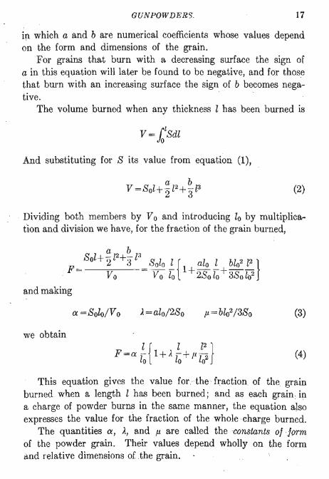
GUNPOWDERS. 17
in which a and b are numerical coefficients whose values depend on the form and dimensions of the grain.
For grains that burn with a decreasing surface the sign of a in this equation will later be found to be negative, and for those that burn with an increasing surface the sign of b becomes negative.
The volume burned when any thickness l has been burned is
And substituting for S its value from equation (1),
(2)
Dividing both members by Vo and introducing lo by multiplication and division we have, for the fraction of the grain burned,
a=Solo/Vo ).= alo/2So (3)
we obtain
l { l l2 } F=a- 1+,l.-+11-lo lo 102 (4)
This equation gives the value for the fraction of the grain burned when a length l has been burned; and as each grain : ip. a charge of powder burns in the same manner, the equation also expresses the value for the fraction of the whole charge burned.
The quantities a, ,l., and p. are called the constants ofJorm of the powder grain. Their values depend wholly on the form c:l.nd relative dimensions of .the grain.

18 ORDNANCE AND GUNNERY.
When Z=1o the whole grain is burned, F becomes unity, and we have the relation
(5)
which may always serve to test the correctness of the values of these constants as determined for any grain.
10. Determination of the Values of the Constants of Form for Different Grains.-In the values of a, A, and fl, equations (3), the quantities So, 10, and Vo are known for any form of grain. We must know in . addition the values of a and b.
When ·Z = 10 the volume burned is the original volume V 0
and equation (2) becomes
·V 8 a b 0= OZO+'2102 +'3Z03
The burning surface at this time, designated by 8', is, from equation (I),
S' =So+alo +bZ02
The values of a and b, if desired, may be derived from these two equations.
Combining the two equations with equations (3) we obtain t~e following values for a, A, and p..
a=Solo/Vo } A=3/a-S' /80 -2 fl=8' /80-2/a+1
(6)
The Vanishing Surlace.-The quantity 8', which represents the vanishing surface, or surface of combustion when l=1o, requires eicplanation. A spherical grain burning equally along all the radii becomes a point as l becomes equal to lo. S' for a sphere is therefore 0, and similarly for a cube. A cylindrical grain, of length greater than its diameter, becomes a line when' l = lo. S' is therefore 0 for this ~ylinder. A flat square grain
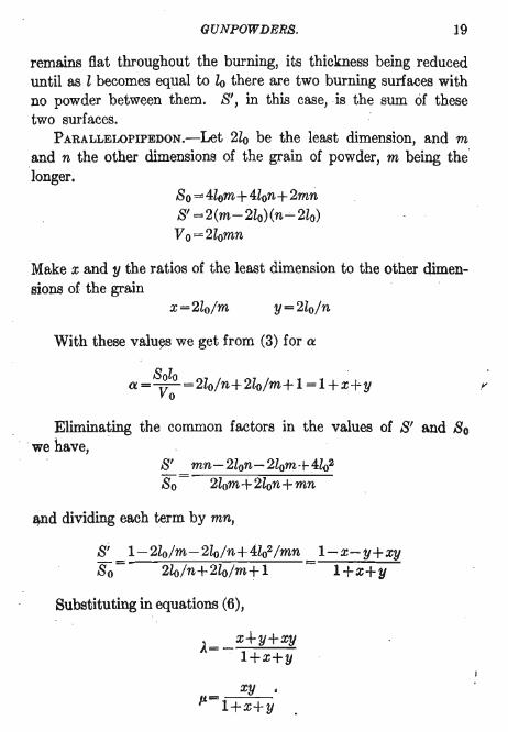
GUNPOWDERS. 19
remains flat throughout the burning, its thickness being reduced until as l becomes equal to to there are two burning surfaces with no powder between them. S', in this case, is the sum of these two surfaces.
PARALLEWPIPEDON.-Let 2lo be the least dimension, and m and n the other dimensions of the grain of powder, m being the longer.
So= 4lom+ 4lon+2mn S' =2(m-2lo)(n...:...210) Vo= 2lomn
Make x and y the ratios of the least dimension to the other dimensions of the grain
x=2lo/m y=2lo/n
With these valu~s we get from (3) for a
Solo . a= Vo =2lo/n+ 210/m+l=1+x+y
Eliminating the common factors in the values of S' and So we have, .
S' mn-2lon-2lom+4l02 So = 2lom+2lon+mn
~d dividing each term by mn,
Si 1-2lo/m-2lo/n+4l02/mn l-x-y+xy So = 2lo/n+210/m+l = l+x+y
Substituting in equations (6),
A=- x+y+xy l+x+y
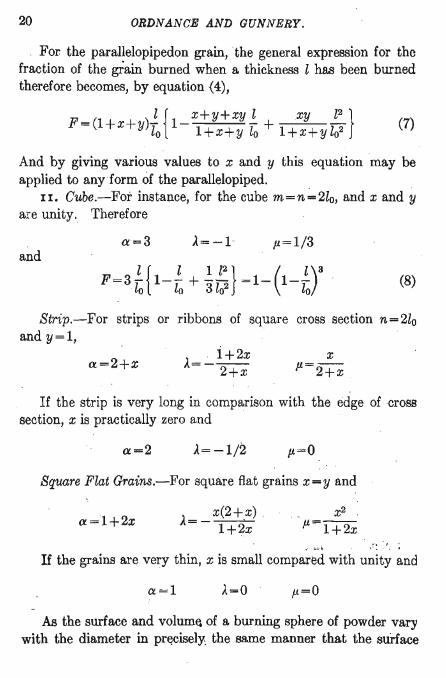
20 ORDNANCE AND GUNNERY .
. For the parallelopipedon grain, the general expression for the fraction of the grain burned when a thickness l has been burned therefore becomes, by equation (4),
. l {. x+y+xy lxy l2 } F=(1+x+ y)yo 1- 1+x+y fo + 1+x+ylo2 (7)
And by giving various values to x and y this equation may be applied to any form of the parallelopiped. .
II. Cube.-For instance, for the cube m=n;"'2lo, and x and y are unity. Therefore
a=3 p=1/3 and
(8)
Strip.-For strips or ribbons of square cross section n=2lo and y=1,
a=2+x x
P=2+x
If the strip is very long in comparison with the edge of cross section, x is practically zero and
a=2 A=-1/2 p=o
Square Flat Grairis.-For square flat grains X=y and
a=1+2x A= _ x(2+,x) . 1+2.x
.' :".:. 1 ", ' r .' ,', ,
If the grains are very thin, x is small compared with unity and
a=1 p=o
As the surface and volum~ of a burning sphere of powder vary with the diameter in pr~cisely: the same manner that the surlace
GUN POWDERS. 21
. and volume of a cube vary with the edge of the cube, the values a, A, and p, see equations (6), will be the same for the sphere as for the cube. And similarly the values of these constants for a cylinder of length greater than its diameter will be the same as for the strips of square cross section, and the values for a flat cylinder will be the same as for the flat square grain.
SPHERE.-For the sphere,
a=3 A=-1 p=1/3
the same as for the cube. 12. SOLID CYLINDER.-For the solid cylinder of length greater
than the diameter, d=21o and x=21o/ml
a=2+x A=_1+2x 2+x
If the diameter is very small compared with the length, as in the slender cylinders or threads of cordite, 2lo is small with respect to m, x is small compared with unity, and approximately
a=2 A=-1/2 p=O
Therefore for cordite
F=2!:.. {1-!.!:..} =1- (1_!:..)2 lo 2lo lo
FLAT CYLINDER.-2lo=thickness, d=diameter, x=2lo/d,
a=1+2x A=- x(2+x) 1+2x
the same as for the flat square grain.
(9)
SINGLE PERFORATED CYLINDER.-Let R be the outer radius of the grain, r the radius of the perforation, and m the length of the
22 ORDNANCE AND GUNNERY.
grain. Make x=2lo/m. By proper substitution we find, for the tubular grain in general,
a=l+x x
).=-l+x p.=o
If the grain is very long compared with its thickness of wall, x is small compared with unity. We then have
a=l and
).=0
F=l/lo
p.=o
(10)
This indicates for long tubes with thin walls a constant emission of gas during the burning of the grain, since F now varies directly with l.
13. MULTIPERFORATED CYLINDER.-A section of the service multiperforated grain before burning is shown in Fig. 1. The
• • • • • • • FIG. 1.
perforations are equal in diameter and symmetrically distributed. The web, 2lo, is the thickness between any two adjacent circumferences. When this t~ickness has burned the section is as shown in Fig. 2. .
There remain now six interior and six exterior three-cornered pieces, called slivers, which burn with a decreasing surface until completely consumed.
The method previously followed cannot be used to find the value of F for the multiperforated grain because the law of burn~

GUNPOWDERS 23
ing for this grain changes abruptly when the grain is but partially consumed.
To find the value of F for this grain we proceed as follows. Let R be the radius of the grain, r the radius of each perfora
tion, m the length of the grain. For the initial volume we have
VO=7'CmCR2-7r2)
When a thickness l is burned, R, r, and m become respectively R-l, r+l, and m-2l, and the volume remaining is obtained from the above equation by making these substitutions. The difference between the two volumes will be the volume burned, and dividing this resulting volume by Vo we have the value of F. This may be reduced to
For the service multiperforated grain we therefore have
a= 21oIR2-7r2+m(R+7r)1
mCR2-7r2)
lo{3m-2(R+7r)1 R2-7r2+mCR+7r)
6102
(11)
(12)
Equation (11) applies only while the web of the grain is burning and does not apply to the slivers.
The thickness of web bears the following relation to Rand r
24 ORDNANCE AND GUNNERY.
in our service grains, as may be readily seen by drawing a diameter through any three perforations, Fig. 1.
D-3d R-3r 2lo = -4- = -2- (13)
We will take a specific grain for use later to illustrate the burning of the multiperforated cylinder. The grains of a lot of powder for the 8-inch rifle had the following dimensions, in inches.
R=0.256 r=0.0255 m=1.029
Therefore, from (13), 10=0.044875. Substituting in (11), we obtain for this grain
1 r 1 l2 } F=0.72667~11+0.19590~-0.02378l02 (14)
When 1 = lo, that is, when the grain is reduced to slivers,
F=0.85174
from which we see that the slivers form about 15 pei' cent of this particular grain.
14. Emission of Gas by Grains of Different Forms.-As the velocity of combustion under constant pressure is uniform, the time of burning will be proportional to the thickness of layer burned.
We may conveniently show the manner of burning of the different grains by dividing the half 'Yeb into five layers of equal thickness, that is, by giving to the ratio l/lo, in the value of the fraction burned, the values 1/5, 2/5, etc., in succession, and then tabulating the resulting values of F. The successive values of F obtained will be the fractional parts burned in 1/5, 2/5, etc., of the total time of burning; and the differences of the successive values of F will be the fractions burned in the successive intervals of time.
GUNPOWDERS. 25
The following table is formed from equations (8) , (9), and (14). For the multiperforated grain the fractions lj lo are fractions of the web only.
Cube.
I Slender Cylinder. Multiperfora ted Cylinder.
li z" F. Difference. F . Difference. F. Difference.
- -0.0 0.000 0 .00 0 .00
0.49 0 .36 0.15 0 .2 0.49 0 .36 0 .15
0 .29 0.28 0.16 0.4 0.78 0.64 0.31
0 .16 0 .20 0.17 0.6 0 .94 0 .84 0.48
0 .05 0 .12 0 .18 0 .8 0 .99 0 .96 0 .66
001 0.04 0.19 - -- --
1.0 1.00 1.00 1.00 1.00 WebO .85 0.85 0.15 -
Whole grain 1.00 1.00
Regarding the columns of differences in the table we see that nearly half of the cubical grain is burned in the first layer, and that the volume burned in the successive layers decreases continuously. The slender cylinder emits at first a less volume of gas than the cube and later a greater volume, that is, its burning is more progressive. We have seen, equation (10), that the long tubular grain burns with a constant surface. The quantity of gas given off in the burning of each layer is therefore the same, and the grain is more progressive than the slender cylinder. The multiperforated cylinder burns with a continually increasing surface Wltil the web is consumed, and the volume of gas given off increases for each layer burned.
Whether the burning surface of the multiperforated grain increases or decreases depends on the relation between the length of the grain and the radii of the grain and of the perforations. Referring to equation (11) it will be seen that when
3m=2(R+7r) (15)
."'"
26 ORDNANCE AND GUNNERY.
the secolld term within the brackets disappears. m is the length of the grain. Giving to the multiperforated grain considered in equation (14) the length indicated in the last equation, we get m =0.29, and the value of F becomes
1 { l2 ) F=0.94892
Zo 1-0.08134Zo2 J
A table formed from this equation will show that this grain burns with a continuously decreasing surface; the fractional volumes burned in the succc'3Sive intervals being 0.189, 0.186, 0.178, 0.167, and 0.152. The sum of these, 0.872, is the fraction of the grain burned when the web ceases to bUrn.
It is apparent that since the manner of burning of a multiperforated grain depends upon the relation expressed in equation (15), a grain may start to burn with an increasing surfacev
and change, as the .length is· diminished, to burn with a decreasing surface.
The multiperforated grains used in our service are of lengths considerably greater than that indicated in equation (15). The length of the grain is about 2t times the outer diameter. The diameter of the perforations is about 1/10 the exterior diameter of the grain. The grains burn with a continuously increasing surface until the web is burned, and then with a decreasing surface.
The Weight of Charge Burned.-Assuming instant ignition of the whole charge, equation (4) expresses the value of the" fraction of the charge burned when any thickness, l, has burned.
Let w be the weight of the charge, y the weight burned at any instant.
The fraction of the charge burned is therefore y/w, which we may write for F in equation (4), and obtain
(16)

GUNPOWDERS. 27
15. Consideration as to · Best Form of Grain.- It would appear that the most desirable form of powder grain would be one that gives off gas slowly at first, starting the projectile before a high pressure is reached, and then with an increased burning surface and a more rapid evolution of gas maintaining the pressure behind the projectile as it moves down the bore.
It is this consideration that has led to the adoption in our service of the multiperforated grain, which in the preceding discussion is shown to be the only practicable form of grain that burns with an increasing surface emitting successively increasing volumes of gas. The facilities for complete inflammation of the charge are .not as great in this grain as in some others, as the grains assume all positions in the cartridge bag, and do not present unobstructed channels to the flame from the igniter. We have seen, page 13, that when there is delay in the complete inflammation of the charge, excessive pressures, called wave pressures, may arise, due to the velocity acquired by the gases first formed. . . r
The single perforated cylinder, or tubular grain, offers advantages in this respect. This grain when ·its length is great compared to the thickness of web, as when cut in lengths to fit the chamber, burns with a practically constant surface, as we have seen, equation (10). The charge is readily prepared by binding the grains in bundles, and when so prepared offers perfect facilities for the prompt spread of ignition through the uniformly distributed longitudinal air spaces within and between the grains.
While larger charges of powder in this form may be required, to produce a desired velocity, the advantages of greater unifor~ity in velocities and pressures, and decreased likelihood of excessive pressures, will probably be obtained by its use.
In the process of drying the tubular grain in manufacture the grain will warp excessively if too long with reference to its diameters. On this account and in order that the grain may serve for convenient building into charges its length is limited. The requirement of prompt ignition throughout the length of th&

28 ORDNANCE AND GUNNERY.
grain also limits its length. Good results have been obtained with grains whose length was 85 times the outer diameter.
VARIOUS DETERMINATIONS.
16. To Determine the Number of Grains in a Pound.-Let n be the number of grains in a pound of powder,
Vo the volume of each grain in cubic inches, (j the density of the powder.
The volume occupied by the solid powder in one pound is evidently nVo; the volume of one pound of water is 27.68 cu. in.; and the volumes being inversely proportional to the densities, we obtain
27.68 n=--avo (17)
and when the number of grains in a pound is known, we have for the density
a=27.68 nVo (18)
To Determine the Dimensions of Irregular Grains.-Irregular grains may be considered as spheres, and the mean radius may be determined as follows. Retaining the above significations of nand Yo, let r be the mean radius of the grains in inches.
Then Vo=4m-3j3. Substituting this in the above equation and solving for r we obtain
1.8766 r= (an)l
Comparison of Surfaces.-Let 81 be the total initial surface of the grains in a pound of powder. As 8 0 is the initial surface of each grain,
GUNPOWDERS. 29
substituting the value of n from (17) and the value of 8 0 from the first of equations (3) we obtain
81 = 27.68a (19)
azo From which it appears that for two charges of equal weight, . made up of grains of the same density and thickness of web, the initial surfaces of the two charges are to each other as the values of a for the two forms of grain. For charges of equal weights composed of grains of the same shape and density the initial surfaces will be inversely proportional to the least dimensions of the grains.
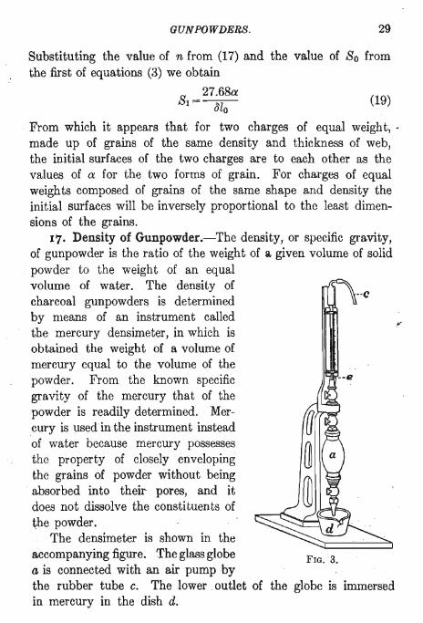
17. Density of Gunpowder.-The density, or specific gravity, of gunpowder is the ratio of the weight of a. given volume of solid powder to the weight of an equal volume of water. The density of charcoal gunpowders is determined by means of an instrument called the mercury densimeter, in which is obtained the weight of a volume of mercury equal to the volume of the powder. From the known specific gravity of the mercury that of the powder is readily determined. Mercury is used in the instrument instead of water because mercury possesses the property of closely enveloping the grains of powder without being absorbed into their pores, and it does not dissolve the constituents of ~he powder.
The densimeter is shown in the accompanying figure. The glass globe a is connected with an air pump by
··c
--e
FIG. ·3.
the rubber tube c. The lower outlet of the globe is immersed in mercury in the dish d.
30 ORDNANCE AND GUNNERY.
Ai:, the globe is exhausted of air by mea~s of the air pump, the mercury is drawn upward until it fills the globe and stands at a certain height in the glass tube e. The globe is then detached, full of mercury, and weighed. It is then emptied, and a given weight of powder placed in it. The globe is then returned to its
. original position; the air again exhausted, and mercury allowed to enter until it stands at the same height as before. The globe, now filled with mercury and powder, is again detached and weighed. With the difference of the two weights we may arrive at the weight of the mercury whose volume is equal to that of the powder, in the following manner.
Let w be the weight of the powder, p the weight of the vessel filled with mercury, pI the weight of the vessel filled with mercury and powder, D the density of the mercury, about 13.56, J the density of the powder.
Then pI - w = the weight of the mercury and vessel when the latter is partially filled with powder,
P-(Pl-w)=the weight of the volume of mercury displaced by the powder.
Since the weights of equal volumes are proportional to the densities, we have
or
w: p_pl+W:: ~:D
~= wD P-P' +w
The density of charcoal powders varies between 1.68 and 1.85.
SMOKELESS POWDER.-The nitrocellulose smokeless powders are affected by mercury; therefore if the densimeter is used in the determination of the densities of these powders, water must be used in the instrument in place of mercury. The density of large grained powders may be determined by weighing a grain
GUNPOWDERS. 31
of the powder in air and in water. The difference of the weights in air and water is the weight of a volume of water equal to the volume of the grain. The density is then the weight in air divided by the difference of the weights.
The density of smokeless powders varies from 1.55 to 1.58.
CHAPTER II.
MEASUREMENT OF VELOCITIES AND PRESSURES.
a
FIG. 4.
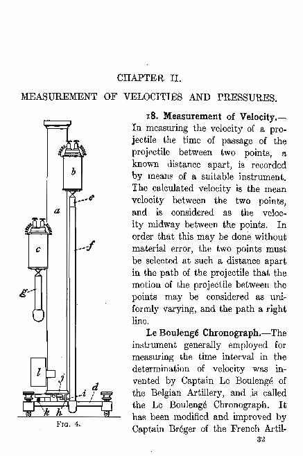
18. Measurement of Velocity.In measuring the velocity of a projectile the time of passage of the projectile between two points, a known distance apart, is recorded by means of a suitable instrument. The calculated velocity is the mean velocity between the two points, and is considered as the velocity midway between the points. In order that this may be done without material error, the two points must be selected at such a distance apart in the path of the projectile that the motion of the projectile between the points may be considered as uniformly varying, and the path a right line.
LeBoulenge Chronograph.-The instrument generally employed for measuring the time interval in the determination of velocity was invented by Captain Le Boulenge of the Belgian Artillery, and .is called the Le Boulenge Chronograph. It has been modified and improved by Captain Breger of the French Artil-
32

MEASUREMENT OF VEWCITIES ' AND PRESSURES. 33
lery. The brass column, a Fig. 4, supporting two electromagnets, b and c, is mounted on the triangular bedplate d which is provided with levels and leveling screws. The magnet b supports the long rod CJ
called the chronometer, which is ,enveloped when in use by a zinc or copp'er tube I, called the recorder. A nut above the recorder, shown in Fig. 10, holds the recorder fixed in place on the chronometer rod. The magnet c which supports the short rod g, called the registrar. is mounted on a frame which permits it to be moved vertically along the standard. Fastened to the base of the standard ' is the flat steel spring h which carries at its outer end the square knife { The knife is held retracted or cocked by the trigger j which is acted upon by the spring k. The chronometer' e hangs so that one element of the enveloping tube or recorder is close to the knife. When the knife is released by pressure on the trigger it flieS out under the action of the sprin.g h and indents the' recorder. The registrar g hangs immediately over the trigger. When the electric
, circu~t through the registrar magnet is broken the registrar falls on the trigger and releases the knife. The tube l supports the registrar after it has fallen through it. Adjustable guides are provided to limit the swing of the two rods when first suspended. The stand or table on which the instrument is mounted is pro-
, vided with a pocket which receives the chronometer when it falls, at the breaking of the circuit that actuates its magnet. A quantity of beans in the bottom of the pocket arrests the fall of the chronometer without shock.
In the use of the chronograph in measuring the velocity of a shot the following accessory apparatus is required: targets, rheostats, disjunctor, and measuring rule.
Targets.-Two wire targets, each made of a continuous wire, Fig. 5, are erected in the path of the projectile. The targets form parts of electric circuits which include the electromagnets of the chronograph. Each magnet has its own target and its own circuit independent of the other. The circuit from the nearer or first target includes tne chronometer magnet; the circuit from

34 ORDNANCE AND GUNNERY.
the second target includes the registrar magnet. On the passage of the projectile through the first target the circuit is broken, the chronometer magnet demagnetized, and the long rod, or chronometer, falls. When the projectile breaks the circuit through the second target the short rod, or registrar, falls and, striking the trigger, releases the knife, which flies out and
;7 marks the recorder -at the point which has been brought opposite the knife by the fall of the chronometer.
FIG. 5. In some instruments the chronQmeter circuit is led through a contact piece not shown, carried by the spring h, and so arranged that the chronometer circuit cannot be closed until the knife is cocked. This arrangement prevents the loss of a record through failure to cock the knife when suspending the rods before the piece is fired.
The first target must always be erected at such a distance from the gun that it will not be affected by the blast. For small arms it is placed three feet from the muzzle and consists of fine copper wire wound backward and forward over pins very close together. For cannon it is placed from 50 to 150 feet from the muzzle, depending upon the size of the gun. For the measurement of ordinary velocities the targets are usually placed 100 feet apart for small arms and 150 feet for cannon.
The second target for small arms consists of a steel plate to stop the bullets, having mounted on its rear face, and insulated from it by the block w, Fig. 6, a contact spring 8, contact pin p, and their binding· screws. When the bullet strikes the plate the shock causes the end of the spring to · leave the pin, and thus breaks
FIG. 6.
the circuit, which is immediately reestablished by the reaction of the spring. By means of this device constant repairing of the target is avoided.

MEASUREMENT OF VELOCITiES AND PRESSURES. 35
19. The Rheostat.-Both circuits are led independently through rheostats, by means of which the resistance in the circuits may be regulated, and the
. strength of the currents through the two magnets equalized. One form of rheostat is shown in Fig. 7. The current passes through the contact spring a and through a German silver wire wound in grooves on the wooden drum b. By turning the thumb nut c the contact spring is shifted, and more or less of the wire is included in the circuit.
Another form of rheostat, through which both circuits pass independently, is shown in Fig. 8.
c
FIG. 7.
o Each current passes through a strip of graphite, a, and the resistance in the circuit may be increased or diminished by sliding the
FIG. 8.
contact piece b so as to include a greater or less length of the graphite strip in the circuit.
The Disjunctor.-Both circuits also pass independently through an instrument called the disjunctor, by means of which they may be broken simultaneously. The disjunctor is shown in elevation and part section in Fig. 9; The two halves of the instrument are exactly similar. The two contact springs c, weighted at their free ends, bear against insulated contact pins e, supported in the same metal frame d. The frame is pressed upward against the

36 ORDNANCE AND GUNNERY.
spring catch h by two other contact springs, I. The electric circuit passes from one binding post through the parts I, e, c, and a to the other binding post.
On the release of the spring catch h the frame d flies upward under the action of the springs 1 until stopped by the pin g.
FIG. 9.
At the sudden stoppage of the movement the weighted ends of the contact springs simultaneously leave the contact pins, thus breaki~g both circuits momentarily. Mounted on a shaft ,are two hard rubber cams, b, which bear against other springs, a, in the two circuits. On turning the cam shaft the connection between the parts a and c is broken, breaking both electric circuits, but not necessarily simultaneously. The circuits are habitually broken in this manner except when taking disjunction or records in firing, .
20. Disjunction.-By means of the disjunctor both circuits are broken at the same instant. The mark made by the lmife under these circumstances is called the disjunction mark, and its height above a zero mark made by the knife when the chronometer is suspended from its magnet is evidently the height through which a free falling body moves in the time used by the instruIflent in making a record. This time includes any difference in the tim~ .required for demagnetization of the two magnetf,l, the timE;) occu-

MEASUREMENT OF VELOCITIES AND PRESSURES. 37
pied by the registrar in falling, and the time required for the knife to act.
From the height as measured we obtain the corresponding time from the law of falling bodies,
t= (2h/g)<t
N ow when the circuits are broken by the projectile the chronometer begins to fall before the registrar. The mark made by the knife will therefore be found above the disjunction mark. If we measure the height of this second mark above the zero, the corresponding time is the whole time that the chronometer was falling before the mark was made, and to obtain the time between the breaking of the circuits we must subtract from this time the time used by the instrument in making a record, or the time corresponding to the disjunction. Let hI and h2 represent the heights of the disjunction and record marks respectively, tI and t2 the corresponding times. Let t be the time between the breaking of screens, then
It will be seen by the equation that the difference of the times, and ~l[)t the difference of the heights, must be taken.
FIXED DISJUNCTION.-For the velocity at the middle point bl?tween targets we have, representing by s the distance between t,Jle targets,
v=s/t
8~\bstituting for t its value, we have
. ~l'om this equation we see that if the value of s, and of (2hdgii, the disjunction, pe fixed, the values of v can be calculated for all va1ues of h2 within the limits of practice, and tabulated. This has been done for the values s = 100 feet and (2hr/g)t =0.15 sec-

38
~ n
0 ~
::
0 N
'" z 1!
I "
!!
ORDNANCE AND GUNNERY.
onds. This value of (2hdg)! is called the fixed disjunction. If such · a table is not at hand, the fixed value of the disjunction avoids the labor of calculating (2hdg)t for each shot.
In this case t=t2-0.15 sec. = (2h2/g)i-0.15.
In ordinary practice it is better to take the disjunction at each shot, and to keep the disjunction mark near the disjunction circle, but not necessarily on it. The times corresponding to the heights of the disjunction and record marks are both read from the table, and with the difference of these times the velocity is taken from another table.
Measuring Rule.-For measuring the height of the mark on the recorder above the zero mark there is provided with the instrument a rule graduated in millimeters, and with a sliding index and vernier, the least reading being -lo of a millimeter. The swivelled pin at the end of the rule, Fig. 10, is inserted in the hole through the bob of the chronometer, and the knife edge of the index is placed at the lower edge of the mark whose height is to be measured. The height is then read from the scale. Tables are constructed from which can be directly read the time corresponding to any height in millimeters within the limits of the scale. The maximum time that can be measured with this chronograph is limited by the length of the chronometer rod, and is about 0.15 of a second.
21. Adjustments and Use.~The instrument must be properly mounted on a stand at such a distance from the gun that it will not be affected by the shock of discharge. The electrical connections with the batteries and targets, through the rheostats rand disjunctor d,
FIG. 10: are made as shown in Fig. 11. To' adjust the instrument, first level it by the level,

MEAf>UREMENT OF VEL'JCITIES AND PRESSURES. 39,
ing screws, cock the knife, and suspend the chronometer rod, enveloped by the recorder, from its magnet. See that the recorder hangs close to the knife and that no part of the base of the rod touches any part of the instrument. The guides must be close to. but not touching, the bob of the chronometer. Depress tl-,e
C::§@Cl==~'---------- ----------------------+Ittlttlttliit
F IG. 11.
trigger. The knife will mark the recorder near the bottom. This mark is the zero from which all heights are measured, and the knife edge on the measuring rule index must be so adjusted that the zero of the vernier shall coincide with the zero of the scale when the knife edge is in the mark. The adjustment of the knife is made as follows. Place the sliding index so that the zero of the vernier is at the zero of the smile on the rule. Clamp the index and apply the rule to the chronometer. Loosen the screws that hold t~e knife ani adjust the knife edge to the zero mark on the recorc1er. Tighten the knife screws. After ihis adjustment, slide the index to the mark Disjunction on the rule, and letting the knife edge bear against the recorder turn the recorder around the chronometer rod. The knife edge will scribe a circle on the recorder, and the mark made at disjunction should fall on or near this circle.
40 ORDNANCE AND GUNNERY.
To regulate the strength of the magnets each of the rods is provided with a tubular weight, one tenth that of the rod. Place the proper weight on each rod and suspend the rods from their magnets. Increase the resistance in each circuit by slowly mov~ ing the contact piece of the rheostat until the rod falls. Remove the weights from the rods and again suspend the rods. Take the disjunction. If the bottom of the mark made by the knife does not lie on or near the circle previously scribed on the recorder, raise or lower the registrar magnet until coincidence is nearly obtained.
Test the disjunctor by shifting the two circuits. The height of disjunction should remain the same.
Test the circuits by suspending the rods and causing the circuits to be broken successively at the two targets. Note that the proper rod falls as each circuit is broken.
Always suspend the chronometer rod with the same side of the bob to the front, and always, before suspending it, press the recorder hard against the bob. After each record turn the recorder slightly on the rod to present a new element to the knife.
Circuits should always be broken at the disjunctor when the rods are not actually suspended, and the rods should be allowed to remain suspended as short a time as possible.
Measurement of Very Small Intervals of Time.-For the measurement of very small time intervals the registrar magnet is raised to near the top of the standard and placed in the circuit with the first target. The chronometer magnet is put .in the circuit with the second target. . Under this arrangement the disjunction mark will be made near the top of the recorder and the record mark under the disjunction. The interval of time measured is obtained by subtracting the time corresponding to the height of the record mark, from the time of disjunction. The object of this arrangement is to obtain the record when the chronometer has acquired a considerable velocity of fall, so. that the scale of time will be ·extended, and small errors of reading will not produce large errors in time.

MEASUREMENT OF VELOCITIES AND PRESSURES. 41
22. Schultz Chronoscope.-The Le Boulenge chronograph measures a single time ' interval only. When it is desired to measure the intervals between several successive events an instru~ ment that provides a more extensive time scale is required.
The Schultz Chronoscope is an instrument of this class. An electrically sustained tuning fork, c, Fig. 12, whose rate of vibration is known, carries on one tine a. quill point b which bears against the blackened surface of the revolving cylinder a and marks on it a sinusoidal curve which is the scale of time. By
FIG. 12. FIG. 13.
giving motion of translation to the cylinder past the fork the time scale may be extended helically over the whole length of the cylinder. The records of events, such as the passage of the shot through screens, are made by the breaking of successive circuits which pass through the Marcel Deprez registers shown at e, Fig. 12, and in Fig. 13. When the circuit is broken the magnet e, Fig. 13, is demagnetized, and the spring g rotates the armature f and the quill h attached to it. This marks a bend or offset in the trac,e of the quill on the revolving cylinder, and the point of the bend referred to the time scale marks the instant of the breaking of the circuit.
.. '

42 ORDNANCE AND GUNNERY.
It will be noted that the tuning fork has a constant lead with respect to any register. The point of the time scale that corresponds to any point on a register record is found at the length . of this lead from the point on the time scale opposite the given point on the register record.
The Sebert Velocimeter.-This instrument is used to record the movement of the gun in recoil. A blackened steel ribbon, S"
FIG. 14.
:fig. 14, is attached by the wire T to a bolt projecting from the trunnion of the gun. As the gun recoils it pulls the ribbon past
the registers R and the tuning fork A, whose rate o of vibration is known. The quill on the tuning
fork marks the time scale on the blackened rib-
FIG. 15.
bon as shown by the curve t, Fig. 15. The time occupied by the gun in traversing any length is obtained by laying off this length on the time scale and counting the vibrations and parts of a vibration included. The right line through the centre of the time scale is made by pulling the ribbon past the fork when the fork is not vibrating. The line assists in the count of the number of double vibrations in any length.
The time scale is therefore a complete record of the movement of the gun; and by measuring from it the length travelled by the gun during any vibration of the fork the velocity of · the gun at the middle instant of the vibration may be determined.

MEASUREMENT OF VELOCITIES AND PRESSURES. 43
When the gun moves in free recoil, that is, when it is so mounted that it recoils horizontally and with very little friction, the velocities of the projectile may be determined from the velocities of the gun; and the pressures necessary to produce these velocities in the projectile may then be determined.
The registers have no function in the measurement of the reCbil proper, but may be used to record any event happening while the recoil record is being made. The instant of the departure of the projectile from the bore is usually thus recorded, and independent measurement of the velocity of the projectile between points in the bore may also be made.
Two register records are shown by the lines T, Fig. 15, the event recorded by each register having occurred when the offset at S waS made. The time that elapsed between the beginning of movement and the occurrence of the event recorded is obtained by laying off on the time scale the length from the origin of the register record to the offset.
Methods of Measuring' Interior Velocities.-Two methodsr that have been used in determining the instant of the projec-
FIG. 16.
tile's passage past selected points in the bore are shown in Figs. 16 and 17.
FIG. 17.
Some circuit breaking device is used at the points selected, and the electric wires are led to any suitable velocity instrument.

44 ORDNANCE AND GUNNERY.
23. Measurement of Pressures.-Pressures in cannon are directly measured by means of the pressure gauge shown in Fig. 18.
In the steel housing h are assembled the steel piston p and the copper cylinder c, which is centered by the steel spring or rubber
FIG. 18.
washer w.The housing is closed by the screw plug s. A small copper obturating cup 0 prevents the entrance of gas past the piston, and a copper washer performs the same office at the joint between the housing and the closing plug. A series of grooves a, called air packing, is sometimes cut near the bottom of the piston, and assists in obturation in the case of a defect in the copper cup. Any gas that may pass
the cup has its tension materially reduced by expansion' into the successive grooves.
In another form of gauge the housing is threaded on the exterior and the gauge is screwed into a socket provided in the head of the breech block.
The gauge is placed in the gun behind the powder charge, or is inserted in its socket in the breech block. When the gun is fired the pressure of the powder gases is exerted against the end of the piston and the copper cylinder is compressed. The compression is manifestly due to the maximum preS8ure exerted in the gun. The length of the cylinder is measured both before and after firing, and the compression due to the pressure is determined. With the compression thus obtained the pressure per square inch that produced it is read at once from a tarage table previously constructed.
The Tarage Table.-The copper cylinders are cut in halfinch lengths from rods very uniformly rolled and carefully annealed. The compression of the cylinders under different loads is determined in a static pressure machine. It is assumed that the compression obtained in firing is due to a load on the piston of the pressure gauge equal to the load that produced the same compression in the static machine. The pressure per square

MEASUREMENT OF VELO']ITIES AND PRESSURES. 45
inch in the gun may therefore be obtained by dividing the static load that corresponds to the observed compression by the area of the piston in the pressure gauge. Knowing the area of the piston used, the table of compressions and corresponding pressures per square inch is readily constructed from the results obtained in the machine.
The area of piston in cannon gauges is l/ 10 of a square inch, and in the small-arm pressure barrel, lho of a square inch.
Initial Compression.-When the pressure in the gun is high the compression of the copper is considerable, and the piston acquires an appreciable velocity during the compression. The energy of the piston due to this velocity adds to the compression that would result from the pressure alone, andtonsequently the measured compression is greater than the compression that corresponds to the true pressure. The energy of the piston may be reduced in two ways: by reducing its weight, and by limiting its travel and accompanying velocity. The pistoil iSl'· made as light as possible consistent with the duty it has to per~ form. To limit its travel the copper cylinders are initially com;.. pressed before using, by a load corresponding to a pressure somewhat less than that expected in the gun. Further compression of the copper will not occur until the load applied in the gun is close to that used in the initial compression.
The general practice is to use a copper initially compressed by a load corresponding to a pressure about 3000 Ibs. less than that expected in the gun. Thus if a pressure of 35,000 Ibs. is expected; a copper initially compressed by a load corresponding to 32,000 Ibs . . per square inch is used.
Sma11-arm Pressure Barrel.-In the measurement of pressures in smaJl arms a specially constructed barrel whose bore is the same as that of the rifle barrel is used. The piston of the pressure gauge passes through a hole bored through the barrel over the chamber, and a steel housing erected over this part of :the barrel servesa.s~n anvil for the copper cylinder.

46 ORDNANCE AND GUNNERY.
A hole is bored through the metallic cartridge case to permit the powder gases to act directly on the end of the piston.
24. The Micrometer Caliper.-The micrometer caliper, Fig. 19, is used for measuring the lengths of the copper cylinders before and after firing. This instrument is used generally for the measurement of ehort exterior lengths.
FIG. 19.
The movable measuring point p has a screw thread of forty turns to the inch cut on its shaft. One turn of the attached micrometer head m therefore moves the point one fortieth or 25 thousandths of an inch. By means of the scale on the spindle and the 25 divisions on the micrometer head m the distance that separates the measuring points can be read to the one-thousandth of an inch, and by further subdividing the divisions on the head by the eye, readings to the ten-thousandth of an inch may be made. The figure represents the points as sepa rated by 0.2907 inches.
The Dynamic Method of Measuring Pressures.-This con sists in determining the velQcities of the gun in recoil, as by the Sebert velocimeter, or of the shot at different points of the bore The differences of the velocities divided by the corresponding differences of the times give the accelerations, and the corresponding pressures are obtained by multiplying the accelerations by the mass. A pressure obtained in this manner is evidently only the pressure required to produce the observed
MEASUREMENT OF VEWCITIES AND PRESSURES. 47
a~celeration in a body whose mass is that of the gun or of the projectile. That part of the pressure expended · in overcoming the friction of the projectile in the bore and in giving rotation to the projectile is neglected. The measured pressure is consequently less than the true pressure exerted in the gun.
Comparison of the Two Methods.-When the same pressure in the bore is measured by the dynamic method and by the pressure gauge the result obtained dynamically is usually the greater, and this notwithstanding the fact, as just explained, that the dynamically measured pressure is less than the true pressure. This causes doubt as to the correctness of the pressures recorded by the gauge.
In the gun the compression of the copper is effected in a very small fraction of the time required in the static machine that produced the tarage, and as the maximum pressure in the gun is instantly relieved, it is held that the metal of the copper cylinder has not time to flow under this pressure, and consequently that the compression is less than it would be under the same load in the static machine. The pressure as obtained from the compression in the gauge is therefore less than the true pressure in the gun.
On the other hand Sarrau, an eminent French investigator, concludes from many experiments that with gunpowder, when the pressure gauge is placed in rear of the projectile, the compressions will agree with the tarage. The maximum pressure in the gun is reached in a very short time, but the time is appreciable. Therefore the application of the pressure resembles in some degree that of the force producing the tarage. When high explosives are used, or when with gunpowder the pressure gauge is placed anywhere in front of the base of the projectile so that the gas strikes it suddenly upon the passage of the projectile, the rate of application of the force is so great that as a general rule the true pressure is measured by the tar age corresponding to half the actual compression of the cylinder.
48 ORDNANCE AND GUNNERY.
Though these differences of opinion as to the correctness of the pressure gauge exist, the gauge itself is in general use. It affords the most convenient method of getting a measure of pressure, and serves to compare the measured pressure with what is known from experience to be a safe pressure in the gun.
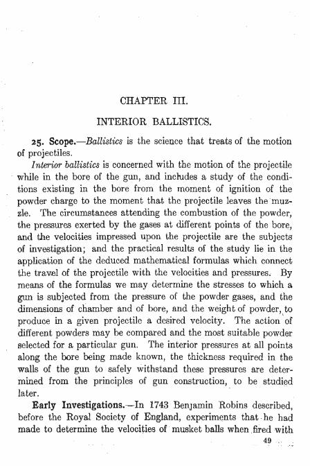
CHAPTER III.
INTERIOR BALLISTICS.
25. Scope.-Ballistics is the science that treats of the motion of projectiles.
Interior ballistics is concerned with the motion of the projectile while in the bore of the gun, and includes a study of the conditions existing in the bore from the moment of ignition of the powder charge to the moment that the projectile leaves themuzzle. The circumstances attending the combustion of the powder, the pressures exerted by the gases at different points of the bore,
rand the velocities impressed upon the projectile are the subjects of investigation; and the practical results of the study lie in the application of the deduced mathematical formulas which connect the trav.el of the projectile with the velocities and pressures. By means of the formulas we may determine the stresses to which a gun is subjected from the pressure of the powder gases, and the dimensions of chamber and of bore, and the weight of powder, to produce in a given projectile a desired velocity. The action 'of different powders may be compared and the most suitable powder selected for a particular gun. The interior pressures at all points along the bore being made known, the thickness required in the walls of the gun to safely withstand these pressures are determined from the principles of gun construction, to be studied later.
Early Investigations.-In 1743 Benjamin Robins described, before the Royal Society of England, experiments that · he had made to determine the velocities of musket balls when fired with
49
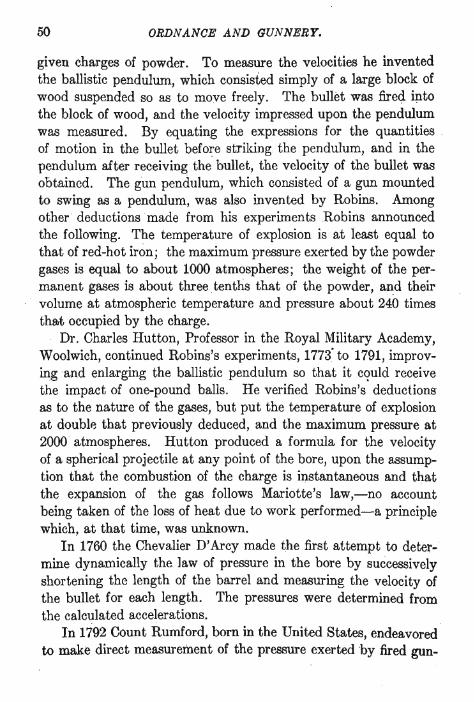
50 ORDNANCE AND GUNNERY.
given charges of powder. To measure the velocities he invented the ballistic pendulum, which consisted simply of a large block of wood suspended so as to moye freely. The bullet was fired ip.to the block of wood, and the velocity impressed upon the pendulum was measured. By equating the expressions for the quantities . of motion in the bullet before striking the pendulum, and in the pendulumaiter receiving the bullet, the velocity of the bullet was obtained. The gun pendulum, which consisted of a gun mounted to swing as a pendulum, was also invented by Robins. Among other deductionsinade from his experiments Robins announced the following. The temperature of explosion is at least equal to that of red-hot iron; the maximum pressure exerted by the powder gases is equal to about 1000 atmospheres; the weight of the permanent gases is about three tenths that of the powder, and their
. volume at atmospheric temperature and pressure about 240 times that occupied by the charge.
Dr. Charles Hutton, Professor in the Royal Military Academy, Woolwich, continued Robins's experiments, 1773· to 1791, improvingand enlarging the ballistic pendulum so that it c<?uld receive the impact of one-pound balls. He verified Robins's deductions as to the nature of the gases, but put the temperature of explosion at double that previously deduced, and the maximum pressure at 2000 atmospheres. Hutton produced a formula for the velocity of a spherical projectile at any point of the bore, upon the assumption that the combustion of the charge is instantaneous and that the expansion of the gas follows Mariotte's law,-no account being taken of the loss of heat due to work performed-a principle which, at that time, was unknown.
In 1760 the Chevalier D' Arcy made the first attempt to determine dynamically the law of pressure in the bore by successively shortening the length of the barrel and measuring the velocity of the bullet for each length. The pressures were determined from the calculated accelerations.
In 1792 Count Rumford, born in the United States, endeavored to make direct measurement of the pressure exerted by fired gun-
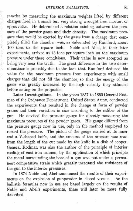
INTERIOR BALLISTICS. 51
powder by measuring the ma,ximum weights lifted by different . . charges fired in a small but very strong wrought iron mortar, or
eprouvette. He determined a relation existing between the pressure of the powder gases and their density. The maximum pres- · sure that would be exerted by the gases from a charge that completely filled the chamber was, as calculated by Rumford, about 100 tons to the square inch. Noble and Abel, in their later experiments, arrived at 43 tons per square inch as the maximum pressure under these conditions. Their value is now accepted as being very near the truth. The great difference inthe two determinations is probably due to the fact that Rumford deduced his value for the maximum pressure from experiments with small charges that did not fill the chamber, so that the energy of the gases was greatly increased by the high velocity they attained
. before acting on the projectile. . Later Investigations.-In the years 1857 to 1860 General Rod
man of the Ordnance Department, United States Army, conducted the experiments that resulted in the change of form of powder grains and their variation in size according to the caliber of the gun. He devised the pressure gauge for directly measuring the maximum pressures of the powder gases. His gauge differed from the pressure gauge now in use, only in the method employed to record the pressure. The piston of the gauge carried at its inner end a V-shaped knife, and the amount of the pressure was read from the length of the cut made by the knife in a disk of copper. General Rodman was also the author of the principle of interior cooling of cast iron cannon, by the application of which principle the metal surrounding the bore of a gun was put under a permanent compressive strain which greatly increased the resistance of the gun to the interior pressures. . In 1874 Noble and Abel announced the results of their experiments on the explosion of gunpowder in closed vessels. As the ballistic formulas now in use are based largely on the results of Noble and Abel's experiments, these will later be more fully described.

52 ORDNANCE AND GUNNERY.
26. Gravimetric Density of Powder.-The density of powder is, as has been explained on page 29, the ratio of the weight of a given volume of powder to the weight of an equal volume of . water. In determining density the volume considered, is the; volume actually occupied by solid powder .
. Gravimetric Density is the mean density of the contents of the volume that is exactly filled by the powder charge. The air spaces between the grains are considered as well as the solid powder in the charge. The gravimetric density is obtained by dividing the weight of the charge by the weight of water that will fill the volume occupied by the charge. It is evident that if a solid block of powder of a given density is broken up into grains, the volume occupied by the powder will increase and will be , dependent on the form and size of the grains. While the actual density of the solid powder does not. change, the gravimetric density will depend upon the granulation.
A cubic foot of powder is usually taken in determining gravimetric density. A cubic foot of water weighs 62.425, lbs.
Let r be the gravimetric density of the powder, W the weight of a cubic foot of powder.
Then, by definition, r= W/ 62.425
If the chamber of the gun were filled with a solid cake of powder, the value of r would be the density of the powder. In practice the value of r usually lies between,O.875 and 1.0, though sometimes the value unity is exceeded. '
The space actually occupied by the solid powder in a given volume is determined as follows-.
Let V be the total volume occupied by the powder, v the volume of the solid powder"
Since volumes of equal weights are inversely as the densities,· we have
V:v: :a:r 'or r v=-V a
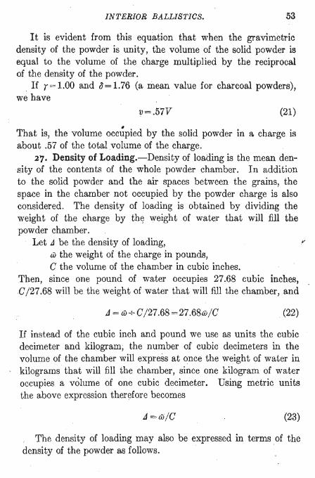
INTERIOR BALLISTICS. 53
It is evident from this equation that when the gravimetric density of the powder is unity, the volume of the solid powder is equal to the volume of the charge multiplied by the reciprocal of the density of the powder.
If r=1.00 and tJ=1.76 (a mean value for charcoal powders), we have
v=.57V (21)
• That is, the volume occupied by the solid powder in a charge is about .57 of the total volume of the charge.
27. Density of Loading.-Density of loading is the mean density of the contents of the whole powder chamber. In addition to the solid powder and the air spaces between the grains, the space in the chamber not occupied by the powder charge is also considered. The density of loading is obtained by dividing the weight of the charge by th~ weight of water that will fill the powder chamber.
Let J be the density of loading, f'
w the weight of the charge in pounds, C the volume of the chamber in cubic inches.
Then, since one pound of water occupies 27.68 cubic inches, ,C/ 27.68 will be the weight of water that will fill the chamber, and
J = w -+- C / 27.68 =27.68w/ C (22)
If instead of the cubic inch and pound we use as units the cubic decimeter and kilogram; the number of cubic decimeters in the volume of the chamber will express at once the weight of water in kilograms that will fill the chamber, since one kilogram of water occupies a volume of one cubic decimeter. Using metric units the above expression therefore becomes
J =&/C (23)
The density of loading may also be expressed in terms of the density of the powder as follows.

ORDNANCE AND GUNNERY.
Let C' be the volume in cubic inches occupied by the solid powder of the charge; iJ the density of the powder. iJC' will then be the volume of an equal weight of water, and
6J = iJC' /27 .68 (24)
which, substituted in equation (22), gives
(25)
The accompanying figure will serve to illustrate the difference between density, gravimetric density, and density of loading. The
figure represents a section of the whole chamber of a gun charged with powder to the line A. The density of loading is in this case the weight of powder below the line A divided by the weight of water that will fill the whole chamber. The gravimetric density is the weight of the powder divided by the weight of water that will fill all that part of the chamber below the line A. Now consider
ing -the powder charge as compressed into a solid mass at the bottom of the chamber, represented by the black portion, the density of the powder will be its weight divided by the weight of water that will fill this black portion. As the weight of water that will fill each volume is equal to the volume in cubic inches divided by 27.68, we have:
27.686J Density of Loading, '.::1 = vol. of ohamber
27.686J Gravimetric Density, r = vol. of charge
Density, iJ- 27.686J - voL of solid powder
Using metric units the factor,27.68 will be omitted.
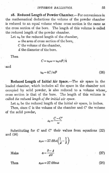
INTERIOR BALLISTICS. 55
28. Reduced Length of Powder Chamber.-For convenience in the mathematical deductions the volume of the powder chamber is reduced to an equal volume whose cross section is the same as the cross section of the bore. The length of this volume is called the reduced length of the powder chamber .
Let Uo be the reduced length of the chamber, w the area of cross section of the bore, C the volume of the chamber, d the diameter of the bore.
Then C = UoW = uo7td2/4
: and
uo=4C/7td2 (26)
Reduced Length of Initial Air Space.-The air space in the ' loaded chamber, which includes all the space in the chamber not occupied by solid powder, is also reduced to a volume whose r cross section is that ~f the bore. The length of this volume is called the reduced length of the initial air space,
Let Zo be the reduced length of the initial air space, in inches. Then, since C is the volume of the chamber and C' the volume
of the solid powder,
C-C' zo=-w-
Substituting for C and C' their values from equations (22) and (24)
ZOW=27.68w(~-- ~)
Make b- t1
a=--.de}
(27)
Then ZoltJ = 27.68aw (28)

56 ORDNANCE AND GUNNERY.
and since w=7rd2j 4
Zo = 35.2441awjd2 = [1.54709]awj d2 (29)
the number in square brackets being the logarithm of 35.2441. Problems.-1. The volume of the chamber of the 3-inch field
. rifle is 66.5 cu. in. The weight of the charge is 26 oz. Density of the powder 1.56. What is the density of loading, and what is the reduced length of the initial air space?
Ans. J =0.6764, Zo = 5.33 inches.
2. If the gravimetric density of the powder in the last example is unity, how many pounds will the chamber hold?
2.4lbs. 3. The reduced length of the initial air space in the 8-inch
rifle loaded with 80 lbs .. of powder, density 1.56, is 43.72 incbes. What is the capacity of the chamber?
0=3617 cu. in. 4. The 5-inch siege gun has a chamber capacity of 402.5 cu . .
in. What is the density of loading with a charge of 5.37 lbs.? J =0.3693.
5. The 4-inch rifle when loaded with 12 lbs. of sphero-hexagonal powder has a density of loading of 0.915. What is the chamber capacity?
0=363 cu. in. 6. The 12-inch rifle has a chamber capacity of 17487 cu. in.
The density of loading is 0.5936. What is the weight of the charge, and what is the volume of the solid powder in the charge? cl=1.56.
w = 375 lbs. Solid volume = 6654 cu. in.
7. What is the reduced ler.gt4 of the initial air space in the last example? .
Zo=95.79 inches.
INTERIOR BALLISTICS. 57
8. The chamber capacity of the 6-inch rifle is 2114 cu. in. What is the reduced length of the chamber?
Uo = 74.77 inches.
PROPERTIES OF PERFECT GASES.
29. Mariotte's Law.-At constant temperature the ~nsion, or pressure, of a gas is inversely as the volume it occupies.
As the density of a gas is inversely as its volume, this law may also be expressed: At constant temperature the pressure of a gas is proportional to its density.
Let v be the volume of a given mass of gas, p its pressure in pounds per unit of area.
Then if the volume occupied by the gas be changed to Vo, the temperature of the gas being kept constant, the pressure will change according to the law
vp = constant
Let po represent the normal atmospheric pressure, barometer 30 inches;
po = 14.6967 pounds per square inch, or 103.33 kilograms per square decimeter;
Vo the volume of unit weight of a gas at 0° C. tmder normal atmospheric pressure.
Then by Mariotte's law, at 0° C.,
VP=VoPo (30)
Specific Volume.-The sJ(ecific volume of a gas is the volume of unit weight of the gas at zero temperature and under normal atmospheric pressure. Vo in the above equation is the specific volume of the gas.
In English units the specific ;volume of a gas is the number of

58 ORDNANCE AND GUNNERY.
cubic feet occupied by a pound of the gas under the abo'ye conditions.
Specific Weight.-The specific weight of a gas is the weight of . a unit volume of the gas at zero temperature and under normal atmospheric pressure. It is the reciprocal of the specific volume.
Gay-Lussac's Law.-The coefficient of expansion of a gas is the saine· for all gases; and is sensibly constant for all temperatures and pressures.
Let Vo be the specific volume of a gas, Vt its volume at any temperature t, and ex the coefficient of expansion. Then the variation of volume under constant pressure by Gay-Lussac's law will be expressed by the equation
or
Vt- Vo =extvo
vt=vo(l+ext)
The value of ex is approximately 1/273 of the specific volume for each degree centigrade. The above equation may therefore be written
(31)
30. Characteristic Equation of the Gaseous State.-The last equation, which expresses Gay-Lussac's law, may be combined with Mariotte's law, introducing the pressure p.
Let x be the volume that Vt would become at 0° C., under the pressure Pt. Then by Gay-Lussac's law
Vt=x(l+ext)
but by Mariotte's law PtX=povo
whence, eliminating x,
Povo p,v, = povo(l + at) = 273 (273 + t)
INTERIOR BALLISTICS. 59
Since Povo/273 is constant for any gas, put
R=povo/273 (32)
whence, dropping the subscripts as no longer necessary,
pv = R(273 + t)
The temperature (273 + t) is called the absolute temperature of the gas. It is the temperature reckoned from a zero placed 273 degrees below the zero of the centigrade scale. Calling the absolute temperature T there results finally
pv=RT (33)
which is called the characteristic equation of the gaseous state, and is simply another expression of Mariotte's law in which the tem-perature of the gas is introduced. Y
Equation (33) expresses the relation that always exists between the pressure, volume, and absolute temperature of a unit weight of gas. To apply it to any gas, substitute for Vo in the value of R, equation (32), the specific volume of the particular gas.
For any number w units of weight occupying the same volume the relation evidently becomes
pv=wRT (34)
A gas supposed to obey exactly the law expressed in equation (33) is called a perfect gas, or is said to be theoretically in the perfectly gaseous state. This perfect condition represents an ideal state toward which gases approach more nearly as their state of rarefaction increases.
For a temperature T' equation (34) becomes
p'v'=wRT'
60 ORDNANCE AND GUNNERY.
Dividing equation (34) by this equation we obtain
pv T p'v'= T' (35)
from which we readily see that if the pressure of any mass of gas is constant the volume of the gas will vary with the absolute tem' perature, and if the volume is constant the pressure will vary with the absolute temperature.
Problems.-Equations (30) to (34) are used in solving the following problems.
Specific volumes: Air ................ Vo= 12.391 cu. ft. Hydrogen ....... " Vo = 178.891 cu. ft. Coal gas .... . ... " Vo = 24.6 cu. ft. Water gas.. . . . . . .. Vo = 18.09 cu. ft.
1. A volume of 3 cubic feet of air, confined at 59° F. (15° C.) and 30" barometer, is heated to a temperature of 300° C. What pressure does it exert?
Vol. of lIb. air at 15°, equation (31), vt=vo288/273.
3/vi=W
Equation (34), p=wRT/v=29.24Ibs. per sq. in. 2. Two pounds of air confined in a volume of 1 cubic foot
exerts a gauge pressure of 679.76 lbs. per square inch. What is its temperature by the centigrade and Fahrenheit scales?
The total pressure p is the gauge pressure plus the atmospheric pressure,
p=679.76+ 14.70=694.46
Equation (34), T=pv/wR=520.54
t=247°.54 C. =477°.57 F.
3. A spherical balloon 20 feet in diameter is to be inflated with hydrogen at 60° F., barometer 30.2 inches, so that gas may not b~ lost on account of expansion when the balloon has risen until

INTERIOR BALLISTICS. 61
the barometer is at 19.6 inches and tlre temperature 40° F. How many cubic feet of gas must be put in the balloon?
The gas pressure in the balloon is in equilibrium with the atmospheric pressure. The weight of gas occupying the balloon must be such that at 40° F. the pressure will be in equilibrium with a barometric pressure of 19.6 inches.
p=PoX19.6j30 v = volume of balloon
Equation (34), w=pvjRT=15.05lbs.
Volume of w at 60° F. and 30".2 barometer:
p=Po X 30.2 j 30 v=wRTj p=2827.4 cubic feet
4. What is the lifting power at 70° F: (21°.11 C.) and 30 In. barometer of 1000 cubic feet of each of the gases whose specific volumes are given? ".
Vol. 1 lb. at 70°. Pounds in Lifting power Equation (31). 1000 cu. ft. 1000 cu. ft.
lbs. Air ...... . ... . . 13.35 74.91 Hydrogen .... . . 192.73 5.19 69.72 Coal gas ... . ... 26.5 37.73 37.18 Water gas . . . . .. 19.49 51:31 23.60
5. The balloon in which Wellman intends to seek the North Pole has a capacity of 224,244 cubic feet, and weighs with its car and machinery 6600 lbs. What will be its lifti~g capacity when: filled with hydrogen at 10° C. and 30 inches barometer?
Ans. 9647 lbs. 31. Thermal Unit.-The heat required to raise the tempera
ture of unit weight of water at the freezing point one degree of the thermometer is called a thermal unit. .
Mechanical Equivalent of Heat.-The mechanical equivalent of heat is the work equivalent of a thermal unit, that is it is, !vh~

62 ORDNANCE AND GUNNERY.
work that can be performed by the amount of heat required to raise the temperature of unit weight of water one degree. It will be designated by E. The unit weight of water being one pound, the value of E for the Fahrenheit scale is 778 foot-pounds; and for the centigrade scale, 1400.4 foot-pounds.
In -metric units the value of E is 425 kilogrammeters. Specific Heat.-The quantity of heat, expressed in thermal
units, which must be imparted to unit weight of a given substance in order to raise its temperature one degree of the thermometer above the standard temperature is called the specific heat of the substance.
The specific heat of a gas may be determined in two ways: under constant pressure, and under ,constant volume.
Suppose heat to be applied to a unit weight of gas retained in a constant volume whose walls are impermeable to heat. The whole effect of the heat will be to raise the temperature of the gas. If, however, the gas is enclosed in an elastic envelope, supposed to maintain a constant pressure on the gas, the gas will expand on the application of heat, and part of the heat applied will perform the work necessary to expand the envelope. Therefore to raise the temperature of the gas one degree, a greater amount of heat must be applied when the gas is under constant pressure than when under constant volume; and the difference of these quantities, th~t - i~~ the difference between the specific heat under constant pressure, Cp , and the specific heat under constant volume, c., will be the heat that performs the work of expansion. The mechanical equivalent of a heat unit being represented by E, we may write •
Work of expansion = (cp-c.)E
Actually, part of the work that we have included in the work of expansion is internal work, used in overcoming the attractions between the mOlecules; but the quantity of work so absorbed i'3 small and is omitted in the discussions.
The work of expansion is equal to the constant resistance mul:' tiplied by the path. We will assume the constant resistance to

INTERIOR BALLISTICS. 63
be the atmospheric prjOlssure, po. The path is measured by the increase of volume of the gas. To determine the path we have from Gay-Lussac's law, for the centigrade scale equation (31),
Vt- Vo = tvo/273
and therefore for an increase of temperature of one degree there is an increase of volume equal to vo/273. The work of expansion for one degree is therefore povo/273. Referring to equation (32),
poVo/273=R
The quantity R is therefore the external work of expansion performed under atmospheric pressure by unit weight of gas when its temperature is raised one degree centigrade. But this work of expansion has been found above to beequal to (cp-cv)E. Therefore we may write
(36) ".
From the definition of specific heat we deduce that the quantity of heat necessary to raise the temperature of unit weight of gas any number of degrees, as t, will be
Q=ct (37)
c representing either Cp orc" . .Ratio of Specific Heats.-In the study of interior ballistics the
particular values of Cp and Cv for the different gases which are formed by the explosion of gunpowder are of little importance. It suffices to know their ratio, which is constant for perfect gases and approximately so for all gases at the high temperature of combustion of gunpowder.
The ratio of the specific heats, cplc", is subsequently designated by n.
32. Relations between Heat and Work in the Expansion of Gases.-The relation which exists between the heat in a unit
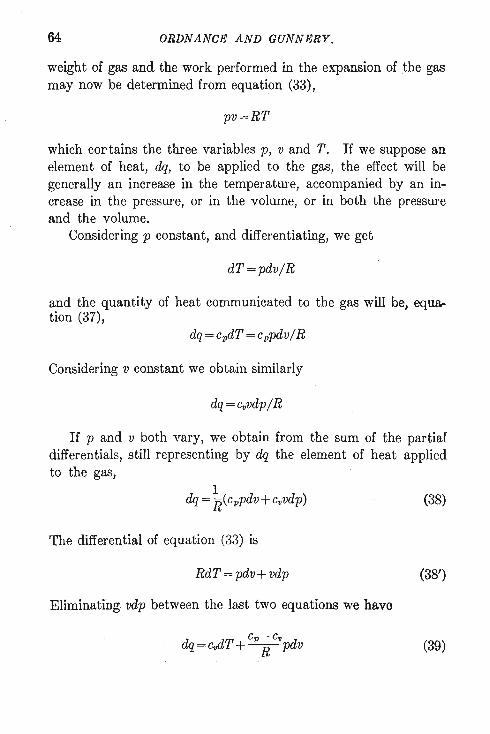
64 ORDNANCE AND GUNNERY.
weight of gas and the work performed in the expansion of .the gas may now be determined from equation (33),
pv=RT
which cortains the three variables p, v and T. If we suppose an element of heat, dq, to be applied to the gas, the effect will be generally an increase in the temperature, accompanied by an increase in the pressure, or in the volume, or in both the pressure and the volume.
Considering p constant, and differentiating, we get
dT=pdv/ R
and the quantity of heat communicated to the gas will be, equation (37),
Considering v constant we obtain similarly
dq=cvvdp/ R
If p and v both vary, we obtain from the sum of the partial differentials, still representing by dq the element of heat applied to the gas,
(38)
The differential of equation (33) is
RdT = pdv + vdp (38')
Eliminating vdp between the last two equations we have
(39)
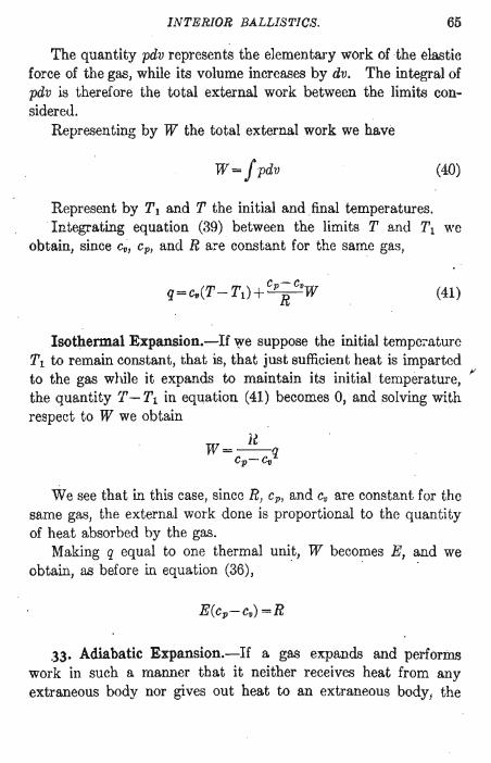
INTERIOR BALLISTICS. 65
The quantity pdv represents the elementary work of the elastic force of the gas, while its volume increases by dv. The integral of pdv is therefore the total external work between the limits considereu.
Representing by W the total external work we have
W=!pdv (40)
Represent by T. and T the initial and final temperatures . . Integrating equation (39) between the limits T and Tl we
obtain, since c~, Cp , and R aye constant for the same gas,
(41)
Isothermal Expansion.-If we suppose the initial temperature Tl to remain constant, that is, that just sufficient heat is imparted to the gas while it expands to maintain its initial temperature, ~ the quantity T- Tl in equation (41) becomes 0, and solving with respect to W we obtain
We see that in this case, since R, Cp , and Cv are constant for the same gas, the external work done is proportional to the quantity of heat absorbed by the gas.
Making q equal to one thermal unit, W becomes E, and we obtain, as before in equation (36),
.33. Adiabatic Expansion.-If a gas expands and performs work in such a manner that it neither receives heat from any extraneous body nor gives out heat to an extraneous body! the
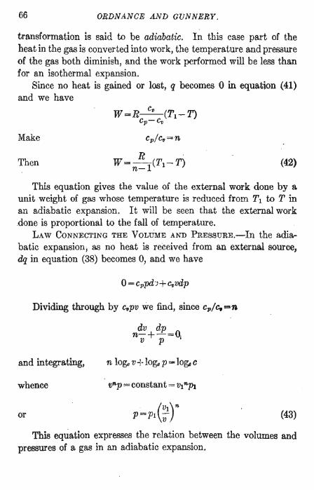
66 ORDNANCE AND GUNNERY.
transformation is said to be adiabatic. In this case part of the heat in the gas is converted into work, the temperature and pressure of the gas both diminish, and the work performed will be less than for an isothermal expansion.
Since no heat is gained or lost, q becomes 0 in equation (41) and we have
Make
Then R
W=-(TI-T) n-l (42)
This equation gives the value of the external work done by a unit weight of gas whose temperature is reduced from Tl to T in an adiabatic expansion. It will be seen that the external work .done is proportional to the fall of temperature.
LAW CONNECTING THE VOLUME AND PRESSuRE.-In the adiabatic expansion, as no heat is received from an external source, dq in equation (38) becomes 0, and we have
Dividing through by C~PV we find, since cp/c.=n
and integrating,
whence
or
vnp = constant = VI npl
(VI)" P=pI -V .
(43)
This equation expresses the relation between the volUnles and pressures of a gas in an adiabatic expansion.

INTERIOR BALLISTICS. 67
NOBLE AND ABEL'S EXPERIMENTS.
34. In 1874 and again in 1880 Captain Noble of the English Army and Sir Frederick Abel published the results of their experiments on the explosion of gunpowder in closed vessels. The purpose of their experiments was to determine definitely the nature of the products of combustion, the volume and temperature of the gases; and the pressures with different densities of loading.
Apparatus.-The steel vessel in which the powder was exploded was of great strength and capable of resisting very high pressures.
The charge of powder was introduced through the opening a
which was then closed with a taper screw-plug. A pressure gauge
d was inserted in the plug c and an outlet was provided at e through which the gas could be drawn off if desired. The charge was fired by electricity.
The vessels were of two sizes. In the larger one a charge of 2.2 pounds of powder was fired, and the gases wholly retained. Black powder was used in the experiments.
The gravimetric density of the powder us'cd was unity, so that

68 ORDNANCE AND GUNNERY.
when the chamber was completely filled the density of loading was also unity.
Results of the Experiments.-Character of the Products.-The products of combustion were found to consist of about 43 per cent by weight of permanent gases, and about 57per cent of non-gaseous products. The non-gaseous products ultimately assume the solid form, but are liquid at the moment of the explosion. This was determined by tilting the vessel at an angle of 45 degrees, one minute after the explosion. Forty five seconds later it was returned to its original position. On opening the vessel the solid residue was found inclined to the walls at the angle of 45 degrees.
The permanent gases are principally CO2 , N, and CO, and the solids K 2C03 , K 2S, K 2S04, and S. With the exception of the K 2S and the free sulphur, the products agree in character with those expressed in the formula generally adopted as approximately representing the reaction of black powder on explosion.
The formula, however, gives 35! per cent by weight of permanent gases and 64~ per cent of solids.
It was found, as was to be expected, that . in a closed vessel variations in the size, form, or density of the grains had practically no effect oli the composition of the products of combustion, or on the pressures.
Volume of Gases.-Noble arid Abel found that the gases, when brought to a temperature of 0° C. and under atmospheric pressure, occupied a volume of about 280 times the volume of the unex.ploded powder.
Specific Volume of Gunpowder Gases.-To simplify somewhat the discussions concerning the gases of fired gunpowder we will use as the specific volume the volume, at 0° C. and under atmospheric pressure, of the gases produced by the combustion of . unit weight of powder. That is, we will consider this weight of gas as unit weight.

INTERIOR BALLISTICS. 69
35. Relation between Pressure and Density of Loading. The relation between the pressure, volume, and absolute temperature of the gases from 61 units of weight of powder at the moment of explosion is given by equation (34).
Make
pV=6IRT
f=RT (44)
and we obtain from (34), for the pressure exerted by the gases from 61 pounds of powder, the gases occupying the volume v at the temperature of explosion,
p= f6l/v (45)
FORCE OF THE POWDER.-If we make both 61 and v unity in this equation, p becomes equal to f. f is therefore the pressure per unit of surface exerted by the gases from unit weight of powder, the gases occupying unit volume at the temperature of explosion. I is called the lorce 01 the powder.
Let a be the volume of the residue from unit weight of powder, C the volume of the chamber.
Then the volume occupied by the gas from 61 units ' of powder will be
v=C-(6)
We may introduce the density of loading, using metric units by substituting for C in this equation its value 6)/ J from equation (23), and obtain
6) v=-(l-aJ)
J
Substituting this value of v in (45) we obtain
J p=I-
I-aJ (46)
This equation expresses the relation between the pressure of the gases Irom 6) units of weight 01 powder and the density of loading.

70
When
ORDNANCE AND GUNNERY.
1 J A =1, that is, when J =-11 -a~ +a
f=p
(46')
Comparing the value of J in equation (46') with the general value, J = wlC, we see that in (46') the weight of powder is unity, and the volume of the chamber 1+a. The volume occupied by the gas is therefore also unity. The pressure therefore becomes in tills case the force of the powder as defined above.
By substituting in equation (46) two observed values of P corresponding to different values of J, the values of a and f were determined. As the means of many observations Noble and Abel finally adopted the values:
a=O.57; ! = 18.49 tons eer square inch =291200 kilograms per square decimeter
The pressure for any density of loading is given by the equation
P = 18.491_ ~.57 J tons per square inch
When J = 1 the equation gives P = 43 tons per square inch. The value of a, 0.57, means that the volume occupied at the
temperature of explosion by the liquid residue from one kilogr:am of powder is 57 /100 of one cubic decimeter. With gravimetric density unity one kilogram of powder occupies one cubic decimeter. Referring now to equation (21), we see that the solid powder, of ordinary density and of gravimetric density unity, occupies 57/100 of the volume of the charge in granular form. The volume of the residue at the temperature of explosion is therefore practically equal to the volume of the solid powder in the charge.
36. Temperature of Explosion.-:-The temperature ofexplosio~ may now be determined from equation (44), which with (32) gives
!=RT=POVOT 273
(47)

INTERlOR BALLISTICS. 71
Vo is the volume occupied by the gas from unit weight of powder. Since the volume of this quantity of gas is 280 times t4e volume of the powder, and one kilogram of powder occupies one cubic decimeter, Vo = 280 cubic decimeters. po, the atmospheric pressure, is 103.33 kilograms per square decimeter. Substituting these with the value of I, 291200 kilograms per square decimeter, we find T =2748° C. As this is the absolute temperature, subtracting 273 we find the temperature of explosion to be 2475° C.
Captain Noble later considered the absolute temperature as 2505° C.
The approximate correctness of these temperatures was verified by the introduction of pieces of fine platinum wire into the explosion chamber. The platinum, which melts at about 2000° C., was partially fused.
Mean Specific Heat of Products.-The quantity of heat given off by one kilogram of powder was found to be 705 calories, that is, the heat necessary to raise 705 kilograms of water one degree centigrade. From the, relation Q = ct, equation (37), t being theV
actual temperature of explosion, not the · absolute, a value was found for the mean specific heat of the products:
705 c=2505-273 0.316
'Relations between Volume and Pressure in the Gun.Noble and Abel found, contrary to their expectations, that the pressures in closed vessels did not differ greatly from the pressures in guns when the powder in the gun was wholly consumed or nearly so. They concluded from this that the expansion of the gases in the gun did not take place without the addition of heat; but that the gases received during the expansion the heat stored in the finely divided liquid residue.
Let Cl be the specific heat of the residue, assumed to be constant, The elementary quantity of heat given up by each unit weight of residue will then be cldT. If there are WI units of weight

12 ORDNANCE AND GUNNERY.
6f residue, Wlc1dT units of heat will be yielded to the gases; and if there are W2 units of weight of gas, each unit will receive, in heat units,
[j being the ratio WI/W2, and the negative sign being used because T decreases while q increases.
Substituting this value of dq in equation (39) it becomes
Eliminate RdT by means of (38') ; divide through by pv, and integrate, considering Cp , C~, Cl and [j constant. We will obtain
(48)
When there is no residue [j is 0, and the equation becomes identical with equation (43), which was deduced for an adiabatic expansion. In both these equations VI and V are the volumes actually occupied by the gases, exclusive of the residue.
Assume the gravimetric · density arid density of loading to be unity, that is, the chamber is filled with powder, and that the powder is all burned before the projectile moves. Then VI in equation (48) will be the volume occupied by the gases in the chamber of the gun, and PI the corresponding pressure. If we call v' the volume of the chamber, av' will be. the volume of the residue, and v' - av' = Vl the volume of the gases; and if we call v" the volume behind the projectile at any instant, the vol~e v occupied by the gases becomes vI' -av' =v. Equation (48) therefore becomes
_ /Jc,+ct. (
V' (1- a») /Jc, +c"
P-PI V" -av' (48')
: ,; .. :.. . ..

INTERIOR BALLISTICS. 73
These values for the constants were determined in the experiments.
PI = 13 tons per square inch a=0.57 v'=27.68w .8=1.2957 Cp = 0.2324 cI=0.45 cv =0.1762
. From these values we find the ratio of the specific heats, cp! Cv = n = 1.32. The value of the exponent in (48') is 1.074.
37. Theoretical Work of Gunpowder.-The general expression for the work done by a gas expanding from a volume VI to a volume vis
w = (" pdv JV1
Substituting for p its value from (43) and integrating,
w=:~~ {l-(~r-I}
Assuming that the powder is all burned before the projectile moves, and that the gravimetric density and density of loading are unity, the values VI and V in this equation may be replaced as indicated in equation (48,), and we obtain
W =PIv'(1-a) {1- (V'(1-a))n-l} n-1 v"-av'
This is the expression for work under the adiabatic expansion for which n=1.32, If we substitute for n the value 1.074, which is the value of the exponent in equation (48'), the equation will then apply to Noble and Abel's hypothesis.
Work at Infinite Expansion.~ When the length of the bore is infinite, v", which is the volume behind the projectile, is infinite, and we have
W =ptV'(1-a) . n-l
74 ORDNANCE AND GUNNERY.
To obtain the work of the gases from one pound of powder make v' =27.68 cubic inches, the volume occupied by one pound, the gravimetric density being unity. Make n=1.32, and substitute for the other constants the values given on page 73. Divide by 12 to reduce from inch-tons to foot-tons.
We find for the work of one pound of powder expanding adiabatically to infinity
w = 133.3 foot-tons per pound.
Substituting for n the value of the exponent in equation (48'), 1.074, we obtain, under Noble and Abel's hypothesis that the gases received heat from the residue,
W = 576.35 foot-tons per pound.
FORMULAS FOR VELOCITIES AND PRESSURES IN THE GUN.
38. Elements Considered. Assumptions.-Formulas connecting the velocity of the projectile with its travel in the bore may be deduced from the relations we have established involving the work of the powder; but these formulas, while they include the force of the powder, do not include consideration of the individual characteristics of different powders, such as form and size of grain, density, and velocity of combustion in the air; nor consideration of the effect on the combustion of the variable pressure in the gun.
M. Emile Sarrau, engineer-in-chief of the French powder factories, was the first to include these elements in hallistic formulaS. He considers the progressive combustion of the · charge under the influence of the varying pressure in the gun, regarding the powder as a variable in the formulas. The individual characteristics or the powder employed enter the formulas, which thereby become applicable to the determination, in advance, of the proper weight of charge, the kind of powde~, the best form and size of grain to produce desired results in a given gun.

INTERIOR BALLISTICS. 75
Sarrau assumes that the time required for complete inflammation of the charge is negligible compared with the time of combustion. He also assumes an _ adiabatic expansion of the gases.
This latter assumption, while incorrect according w the experiments of Noble and Abel, is now generally made by writers on interior ballistics; and whatever error is introduced through the assumption is later corrected' in the determination, by experiment, of the constants in the formulas.
Principle of the Covolume.-Another assumption of important bearing in the deduction of the ballistic formulas will now be explained.
The characteristic equation for perfect gases, equation (33), _combined with equation (47) gives for the pressure from unit weight of gas confined in the volume v,
p=//v
But it has been found by experiment that for the gases of explosion the law expressed by this equation does not hold, and that to obtain the true value of the pressure we must diminish the volume v, which is the volume of the explosion chamber, The true equation must therefore be of the form
p=-'-v-a (49)
, We may call the volume v-a the effective volume of the gas. Theoretical deductions indicate that the subtractive volume a
is the ' actual volume of the incompressible molecules in a unit weight of powder gas; that is, it is the limiting volume beyond which ,a unit weight of gas cannot be compressed.
The volume a is called the covolume. Sarrau determined by experiment with different gases that the mean value of the covolume is one one-thousandth of the specific volume of the gas. Other writers take, for convenience, the reciprocal
76 ORDNANCE AND GUNNERY.
of the density of the powder as the covolume, this value not differing greatly from the other. We have seen, equation (20), that when the gravimetric density is unity the volume of the solid powder in unit volume of the charge is the reciprocal of the density of the powder. The assumption of the reciprocal of the density as the covolume is equivalent therefore to considering the covolume as the volume originally occupied by unit weight of solid powder.
Under this assumption the volume v-a, equation (49), which is the effective volume of unit weight of the powder gases; becomes the volume of the powder chamber minus the volume of the solid powder in unit weight of the charge.
The effective volume of the gases from the whole charge will therefore be the volume of the powder chamber minus the volume of the solid powder in the whole charge.
But this is the initial air space in the chamber. Therefore the effective volume occupied by the powder gases in the chamber is the initial air space.
If the powder leaves a non-volatile residue, the volume of this residue at the temperature of explosion must be added to the covolume of the gases formed. a in equation (49) will then represent thecovolume of the gases from unit weight of powder plus the volume of the residue from unit weight of powder.
39. Differential Equation of the Motion of a Projectile in a Gun.-Let
y be the weight of powder burned at the time t, Tl the absolute temperature of combustion, T the absolute temperature of the gas at the time t.
The work of a unit weight of gas in an adiabatic expansion between the temperatures Tl and T is given by equation (42). For a weight of gas y we have
yR W=-(T1-T)
n-l
INTERIOR BALLISTICS. 77
From equation (44), since Tl now represents the temperature of explosion, the value for the force of the powder is f= RT 1; and from equation (34), pv=yRT. With these substitutions the above equation becomes
(n-1)W =fy-pv (50)
In this equation v is the volume occupied by the · gases at the temperature T and at the time t.
Let u be the distance traveled by the projectile at the time t, w the cross section of the bore,
Zo the reduced length of the initial air space. Under the assumption of the volume originally occupied by
unit weight of solid powder as the covolume of the gases, the initial air space in the chamber becomes the volume occupied by the powder gases in the chamber.
We therefore have, for the volume occupied by the gases at the time t,
v=w(zo+u)
Substituting this value in equation (50) we have
(n-1)W =fy- wp(zo+u) (51)
an equation expressing the relation at each instant between the weight of powder burned, the pressure, the travel of the projectile, and the external work performed.
In introducing the velocity of the projectile we will assume that the whole work of the gas is expended in giving motion of translation to the projectile. Making w the weight of the projectile, and representing now by v the velocity of the projectile,
p in (51) is the pressure per unit of area; wp the total pressure

78 ORDNANCE AND GUNNERY.
on the base of the projectile. The acceleration of the projectile is d2ujdt2. The total pressure on the base of the projectile is equal to the product of the mass by the acceleration. Therefore
52)
Substituting these values of Wand wp in (51) we have
(53)
which is Sarrau's differential equation of the motion of a projectile in the bore of a gun.
In deducing this equation there were neglected the following energies.
The heat communicated by the gases to the walls of the gun, The work expended on the charge, on the gun, and in giving
rotation to the projectile, The work expended in overcoming passive resistances, such as
the forcing of the band, the friction along the bore, and the resist-ance of the air .
. Dissociation of Gases.-The error committed by the omission of these energies may not be as great as would at first appear, for we have also omitted from consideration the heat supplied by the phenomenon called dissociation. Acr.ording to Berthelot the composition of the complex gases from fired gunpowder is not permanent, and at the high temperature during the first instants of explosion these gases decompose into more simple combinations: perhaps into their elements. The increase in volume due to the
,..-displacement of the projectile causes a reduction in the tempera-ture, which permits the dissociated gases to combine again with a consequent development of heat. The theory of dissociation forms the basis for the assumption of some writers on ballistics, notably Oolonel Mata of the Spanish artillery, that by reason of this phenomenon the expansion of the gases in the gun takes place

INTERIOR BALLISTICS. 79
a;s though the gases received heat from the exterior, and not adiabatically.
It will be seen, however, from the form of equation (53) that the errors of assumption may be allowed for by giving to f a suitable value, and this without changing the form of the differential equation of motion. The force of the powder as it appears in equation (53) can therefore be considered only as a coefficient whose value must be determined by experiment.
Sarrau deduced from the differential equation of motion formulas for the velocity and pressure as functions of the travel of the projectile.
40. Ingalls' Formulas.-We will now follow Colonel Ingalls, United States Army, in the deduction of his formulas. These formulas are considered as giving more accurate results than Sarrau's formulas, for the velocity and pressures produced by modern powders in the bore of the gun; and the use of ~arrau's formulas is generally limited to the determination of muzzle velocities and maximum pressures.
Let v be the velocity of the projectile in the bore at the time t. Then
and
(54)
Substituting these values in equation (53) it beoomes ,
d(V2) 2fg (zo+u)--+ (n-l)v2=-y
du w (55)
The true value of n, the ratio of the specific heats, cplc., is uncertain. For perfect gases its value is 1.41. Regarding the powder gases at the high temperature of explosion as perfect gases, earlier writers assumed this value for n. Recent investigations
80 ORDNANCE AND GUNNERY.
have shown that the value of 1.41 is too great. 'Some recent writers adopt the value unity for n. As we have seen, equation (35), the work of expansion is directly proportional to the difference of the specific heats; and if their ratio is unity and the difference between them zero, there can be no external work performed. The assumption of the value unity is made for convenience, and the error due to the assumption is compensated for, with the other errors, in the experimental determination of the values of the constants.
Ingalls assumes the value n=4/ 3, which is practically the value deduced from the experiments of Noble and Abel, see page 73.
Making n=4/3 in equation (55) we obtain
d(v2) 6/g 3(zo+u)--+v2 =-y
du w (56)
Make x=u/zo (57)
Under the assumption made that the covolume of the gases is equal to the volume occupied by the solid powder in the charge, the initial air space is the volume occupied by the gases in the powder chamber. Considering zo,which is the reduced length of the initial air space, as the measure of this volume, x in equation (57), x=u/zo, becomes the number o/expansions 0/ the volume occupied by the powder gases in the chamber, when the projectile has traveled the distance u.
I t is important to bear in mind that x represents a number of expansions, and u the distance traveled by the projectile.
Making x=u/zo, equation (55) becomes
d(v2) 6/g 3(1+x)~· -+v2 =-y
dx w (58)
y, the weight of powder burned, is a function of the time and also of the travel u, and of x. The integration of this equation

INTERIOR BALLISTICS. 81
even when the simplest admissible form of y as a function of x is assumed has not yet been possible.
Considering y constant the equation may be integrated. Rearranging it,
And integrating,
d(v2) dx v2- 6fgy + 3(1+x) 0
w
When x=O, v=O, and C=-6fgy/w. Therefore
v2 = 6fgy { 1- 1 l w (l+x)t J
(59)
Making y constant in equation (58) is equivalent to assuming • instantaneous combustion for that part of the charge that has burned at the time t. We know this to be in error since the combustion of the charge is progressive. If, however, we determine the values of the constants in the equations by substituting measured values of v, we obtain an equation that is true for the measured values, and may be true for other values of v at other points in the bore. Only by experiment can we determine whether r,esuIts obtained under this supposition are correct; and experiment, as stated by Colonel Ingalls, is the final test of nearly all physical formulas.
41. Velocities in the Bore.~To make equation (59) applicable to points in the bore we must determine a relation between the quantity of powder burned at any instant and the corresponding travel of the projectile, that is, we must determine the value of y as a function of u or x. Then substituting for y in the equation this value, which for any powder will contain x as the only variable, we will have the desired ' equation expressing the relation .between the velocity of the projectile and its travel in the bore.
82 ORDNANCE AND GUNNERY.
Combustion under Variable Pressure.-We-have previously deduced, page 26, an expression for the quantity of the powder burned, under constant pressure,as afunction of the thickness of layer burned. This relation is given by equation (16) on that page.
1 r 1 12 } y=6Ja -i 1+ A -+.u-
10 L lo 102 (60)
in which y is the weight of the powder burned when a thickness of layer 1 has been burned, 6J is the weight of the charge, lo is half the least dimension of the powder grain, and a, A, and .u are consta.nts of form of the grain. .
Representing by , the time of combustion in air of the whole grain, or charge, the uniform velocity of combustion will be lo/'.
In the gun the powder burns under variable pressure, and the velocity of combustion if? expressed by d1/ dt. Assuming that the velocity of combustion varies as some power of the pressure, and representing by po the pressure of t~e atmosphere under which the
. velocity of combustion is lo/', we obtain the equation
dl =~(E)'" dt , po (61)
in which p represents the pressure on the base of the projectile at any instant.
The exponent 1> is given different values by different writers. Sarrau assumes 1> = 1/2. Recent experiments indicate a mean value of 0.8. The value unity is assumed by other writers. Ingalls assumes the value 1/2 with Sarrau.
The pressure per unit of area on the base of the projectile is, from equation (52),
(62)
Substituting this value of p in equation (61) and using equation

INTERIOR BALLISTICS. ·· ·
(54) and the relations
and
dx 1 du v u=xzo, ,'. dt = zodt = Zo
equation (61) may be brought to the form
dl =~( . wZo )i(d(V2))i!.. dx 't' 2gwpo dx v
Integrating and dividing by lo,
1. =~(~)iJ(d(v2))i ~ lo 't' 2gwpo dx v
Make
Then l/lo=KXo
Substituting this value in (60) we have
(63)
(64)
(65)
(66)
42. DISCUSSION OF VALuEs.-The value of K in thi!l equation is composed wholly of constants. a, A, and p. are the constants of form of the powder grain. By the differentiation of equation (59) and substitution in (64), see foot-note, page 84, we find for the value of X 0
J dx'
Xo= v (l+x).j(l+·x)i-ll (67)
84 ORDNANCE AND GUNNERY.
Xo is therefore a function of x only, and x from its value, x=u/zo, is itself a function of the travel of the projectile. Equation (66) therefore expresses, for powder of any particular granulation, the relation between the weight burned at any instant and the corresponding travel of the projectile.
This equation may be put into another form. At the instant that the powder is all burned in the gun, y = w
and l = lo. We will distinguish the particular values of the various quantities at the instant that the burning of the powder is completed by putting a dash over the symbol.
When y=w and l=lo, equations (65) and (66) then become
KXo=l (68)
1 =a(l + A+,u)
This last relation has been previously established in equation (5) .
. Substituting the value of K from (68) in (66), we obtain
~ =::. Xo { l+ -~ Xo+ -~ X02 } W Xo Xo X02
(69)
We have now, in Xo, introduced into the value of y the travel of the projectile at the specific instant that the burning of the charge is complete.
(59)
6!gy!w=A
From equation (64), X - f dx . 0- yI(1+:t)\(1+x)LlI
INTERIOR BALLlSTICS. 85
Make
X1=Xo { t- (l~X)t} (70)
and Xt/XO=X2 (71)
whence (72)
From equation (59) we obtain for the velocity at the instant that the burning of the charge is complete,
(73)
43. Velocity 6f the Projectile while the Powder is Burning.~Substituting in equation (59) the value of 6gf from (73) and the value of y from (69), using equation (71), and making
). N==
Xo
equation (59) reduces to the form
(74)
This equation expresses the value of the velocity of the projectile at any instant while the powder is burning, in terms of the variable travel of the projectile, and of its velocity and travel at the instant of the complete burning of the charge.
Velocity after the Powder is Burned.-Distinguish with the 'subscript a the values of v and p after the charge is completely b'urned. y is then equal to w, and equation (59) when combined with (73) and (72) becomes
(76)

85 ORDN ANCE AND GUNNERY.
and making (77)
we have (78)
which is the formula for the velocity after the-powder is all burned. This equation is identical with equation (59), if in the latter
we make y=w. V12=6fgw/w, see (73) and (77), and X 2 is an abbreviation for the quantity in brackets, see (72).
As explained under equation (59), equation (78) is therefore the equation of the velocity under the supposition that the powder is all burned before the projectile moves.
The Velocity V1.-From equation (78) we see that V1 is what Va becomes when X 2 is equal to unity; and, equation (72), X 2 is unity when x is infinite. V1 is therefore the velocity corresponding to an infinite travel of the projectile. ..
. 44. Relation between the Velocities Before and After the Burning of the Charge.-Make
k = y / w = fraction of charge burned.
Replacing M, N, and N' in equation (75) by their values, and combining with equations (69), (70), and (76) we may establish the relation
(79)
That is, the velocity of the projectile before the charge is consumed is equal to what the velocity would have been at the same point if all the charge had been burned before the projectile moved, mUltiplied by the square root of the fraction of charge burned.
Relation ·between the Weight of Powder Burned and the Velocity and Travel of the Projectile.-Replacing Va in equation (79) by its value from (78) we obtain
(80)
equations that will be fOl1nd cQnveni~mt for determining the frac-

INTERIOR BAtLI8T1GS. 87
tion of charge or weight of powder burned when the velocity and . travel of the projectile are known.
By reason of the form assumed by the value of kfor certain grains very simple relations may be established, for these grains, between the fraction of charge burned and the travel of the projectile.
CUBICAL, SPHERICAL, AND SPHltROIDAL GRAINs.-For cubical grains a = 3, A = - 1, and p = 1/3 (see page 20). These values apply . also to spherical and spheroidal grains. Substituting them in equation (69) we obtain
( XO)3 k=1- 1-Xu (81)
and Xo=Xo\1- (1-k)t}
From the first ().quation we may obtain the fraction of charge burned for any travel of the projectile, and the converse from. the second. •
SLENDER CYLINDRICAL AND PRISMATIC GRAINs.-For long slender cylinders
k=1- (1-~:r (82)
Xo=Xo{1- (1-k)t}
which also apply to grains in the form of long slender prisms of square cross section.
For other forms of grain the solution of a complete cubic equation is necessary to determine Xo when k is known.
45. Pressures.-The general expression for the pressure per unit of area on the base of the projectile is given in equation (62). Transforming this equation by means of (54) a.nd (57) we obtain
wd(v2 )
P=2gwzo CiX (83)
By substituting in succession the values of d(v2)/dx obtained
88 ORDNANCE AND GUNNERY.
from the equations for velocity before and after the complete burning of the charge we will obtain the values of p that apply before and after the charge is burned.
Pressure While the Powder is Burning.- Finding the value of d(v2)jdx from equation (75), see foot-note, and making
X3=dXddx
X1dXo X 4 =XO+ -X 3dx
X -X 2 2X1X odXo 5- 0 + X
3dx
M'= Mw 2gwzo
(84)
(85)
we obtain for the pressure per unit of area on the base of the projectile while the powder is burning
p=M'X3!1+NX4 +N'X5 1 (86)
It will be observed that X 3 , X 4, and X 5 are all functions of x only. The logarithms of their values for various values of x will be found in Table I at the end of the volume.
Pressure After the Powder is Burned.- Finding the value of d(v2 )jdx from equation (78), V12 being constant, we obtain with the aid of (72)
d(v a2 ) V 12dX2
dx dx
v2=MX,11+NXo+N'Xo2!
d(v2)=MdX, +MN (x dX,+X dXo) +MN'(X 2
dX' +2X X dXo) dx dx °dx 'dx 0 dx l°dx
Make dX,=x. dx
d(v2)=MX j l+N (x + X,dXo) + N' (x 2+ 2X,XadXo) ~
dx .~ 0 X.dx 0 X 3 dx )
(75)
INTERIOR BALLISTICS.
Substituting in (83) and ma~ing
P'= WV12
6gwzo
89
(87)
we obtain for the pressure per unit of area on the base of the projectile after the powder is all burned
p' (88) pa (l+x)!
46. Maximum Pressure.-The maximum pressure in a gun occurs when the projectile has moved but a short distance from its seat, or when u and x are small. The position of maximum pressure is not fixed, but varies with the resistance encountered. As a rule it will be found that the less the resistance to be overcome by the expanding gases the sooner will they exert the maximum pressure and the less · the maximum pressure will be. By the differentiation of equation (86) we may obtain the value for the maximum, but it is too complicated to be of practical use. Examination of the table of the X functions shows that X3 is a maximum when x=O.65, nearly, while X4 and X5 increase indefinitely. The functions X 3 , X 4 , and X5 are found to vary in such a manner that when A, and therefore N, see (74), is negative, that is, when the powder burns with a decreasing surface, p will be a maximum when x is less than 0.65; and when A and N are positive or when the powder burns with an increasing surface, p will be a maximum when x is greater than 0.65.
A function at or near its maximum changes its value slowly. Therefore a moderate variation of the position of maximum pressure will have no practical effect on the computed value of the pressure. It has been found by experiment that if we take x=0.45 for the position of maximum pressure when ;. .is negative, and x = 0.8 when A is positive, no material error results.
Therefore to obtain the maximum pressure make x=O.l,5, in equation (86) when the powder burns with a decreasingsurlace,
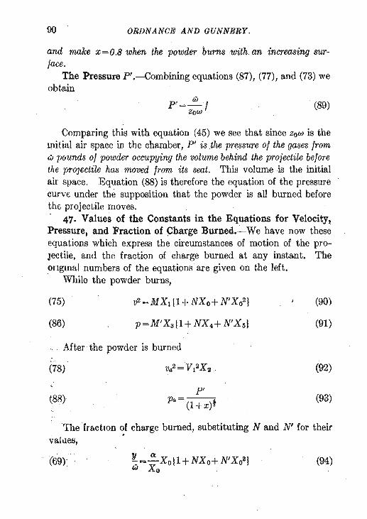
90 ' ORDNANCE AND GUNNERY.
and 'make x=O.B when the powder bUTnswith, an increasing sur~ face.
The Pressure P'.-Combining equations (87), (77), and (73) we obtain
pl= IiJ 1 ZoW
(89)
Comparing this with equation (45) we see that since ZoW is the l,nitial air space in the chamber, p, is the pressure of the gases from w pounds of powder occupying the volume behind the projectile before the proJectile has moved from its seat. This volume is the initial air space. Equation (88) is therefore the equation of the pressure curve under the supposition that the powder is all burned before thE, projectile moves.
47. Values of the Constants in the Equations for Velocity, Pressure, and Fraction of ~harge Burned.~ We have now these equations which express the circumstances of motion of the proJectile, and the fraction of charge burned at any instant. The ongmal numbers of the equations are given on the left.
While the powder burns,
(75) v2=MX1 Il+NXo+ N'X021 (90)
(86) p=M'Xa{1+ NX4+ N'X 51 ,(91)
After the powder is burned ....
Va2 ='V12X 2 " (78) (92)
(88) p'
(93) pa= (l+x)* "
l ' The '[ractlOn of charge burned, sUbstituting Nand N' for their values,
. (69): ' (94)

INTERIOR BALLISTICS. 91
The quantities M, N, N' , M', VI, pI and Xo in these five equations atc constant for any experiment, and their values must be determined before the equations can be used. It will be seen in the equations that express the values of these constants, equations (74), (77), ' (85), and ' (87), that the quantities entering the values are of tWb kinds: the known elements of fire-by which is meant the constants of the powder, of the gun, and of the projectile-and quantities such as V, Xo, Xl, etc., that involve the velocity and travel of the projectile at the instant that the powder is all burned.
When M and N are known all the constants are known . . The value of M given in equation (74) may be redueed by
, means of (77) and (71) to
(95)
We have, equation (74),
N=A/XO (96,
M and N being known, Xo and V l2 are determined from these
equations, and N', M', and P' become known from (74), (85), and (87).
Therefore when M and N are known the five equations, (90) to (94), are fully determined, and all the circumstances attending
-' the movement of the projectile become known from them. For any assumed travel of the projectile u, the number of expansions, x=u/zo, is obtained, and with-this value of x the functions Xo to X5 are obtained from Table 1. These substituted 'with the constants in, the equations give t,he values of v, p, and y. Proceeding in this manner" for a nUl~ber of points along the bore complete
. curves may be , Gonstructed showing the values of v, p, and y for any point in the bore of the gun.
, The value of x corresponding to Xo is obtained from the table. The value of it, follows from ',the equation it, = xZo. This valu~ u is the distance that ·;the projectile has travelled' at the moment

92 ORDN1tNOE AND GUNNERY.
that the charge is completely burned. For values of 1.1. less than this, . equations (90), (91), and (94) apply; for greater values of 1.1. equations (92) and (93) apply.
48. Determination of the Constants by Experiment.-Regarding equation (90) and, noting from equations (74) that N' is a function of N, it will be seen that if we measure two velocities at known
. points in the bore of the gun we can determine M and N from equation (90). x being known for each of the points the X functions are obtained from the table. With the two measured values of v we then form two equations in which M and N are the only unknown quantities. Determining M and N the other constants become known.
In using this method care must be exercised that the measured velocities are taken at points passed by the projectile before the powder has completely burned. If the powder is not wholly burned when the projectile leaves the gun one of the measured velocities may be taken at the muzzle.
Since M' is also a function of M, equation (85), we may make use of the two equations (90) and (91), or (92) and (91), and with a single measured velocity and a measured pressure determine M -
. and N from these equations. But it has been shown in the chapter on powders that there is room to believe that the pressures as ordinarily measured with the crusher gauge are not reliable. Therefore results obtained in this way are not likely to be as satisfactory as those obtained from measured velocities, which can be determined with a high degree of accuracy.
It is found in fact that while the velocities obtained from the formulas agree very closely with those actually measured in practice, there is not as satisfactory an agreement between the pressures. The pressures are obtained in the formulas by the dynamic method and are usually higher than the measured pressures. This is in accord with what has already been said in our previous consideration of the subject of pressures, and adds to the evidence ag!',inst the accuracy of the crusher gauge.
When 't' and f are known all the constants are known.
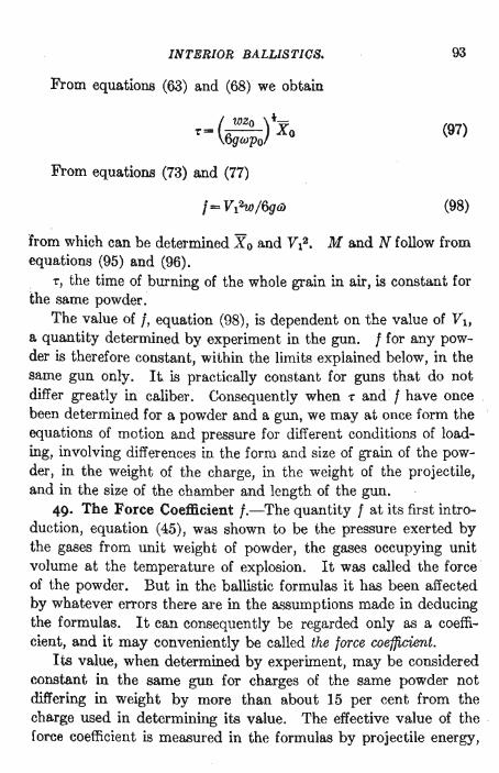
INTERIOR BALLISTICS.
From equations (63) and (68) we obtain
't'= ( wZo )iXO 6gwpo
From equations (73) and (77)
f= VI2W/6g6>
93
(97)
(98)
from which can be determined Xo and V12. M and N follow from equations (95) and (96).
't', the time of burning of the whole grain in air, is constant for the same powder:
The value of f, equation (98), is dependent on the value of VI, a quantity determined by experiment in the gun. f for any powder is therefore constant, within the limits explained below, in the same gun only. It is practically constant for guns that do not differ greatly in caliber. Consequently when 't' and f have once been determined for a powder and a gun, we may at once form the equations of motion and pressure for different conditions of loading, involving differences in the form and size of grain of the powder, in the weight of the charge, in the weight of the projectile, and in the size of the chamber and length of the gun.
49. The Force Coefficient I.-The quantity I at its first introduction, equation (45), was shown to be the pressure exerted by the gases from unit weight of powder, the gases occupying unit volume at the temperature of explosion. It was called the force of the powder. But in the ballistic formulas it has been affected by whatever errors there are in the assumptions made in deducing the formulas. It can consequently be regarded only as a coefficient, and it may conveniently be called the lorce coefficient.
Its value, when determined by experiment, may be considered constant in the same gun for charges of the same powder not differing in weight by more than about 15 per cent from the charge used in determining its value. The effective value of the foree coefficient is measured in the formulas by projectile energy,

94 ORDNANCE AND GUNNERY.
and there has been omitted in deducing the formulas all considera~ tion of the force necessary to start the projectile. .Ai3 the charge decreases the portion of the developed force necessary to start the projectile bears a larger relation to the t~tal force exerted; and if the charge is sufficiently small the projectile will not start at all. The effective force for a small charge must therefore be proportionally less than for a large charge, and the value of I determined from one charge must be modified for use with another that differs greatly in weight. The formula used by Ingalls for this modification will be found in equation (137), problem 3 of the applications which follow . .
Values of the X Functions.-We may simplify the value of Xo by means of circular functions. In equation (67) make
sec 8=(1+x)i
we may then deduce, see loot-note,
X 0 = 6 f sec3 8 d8
The value of this integral, designated as (8), is given in Table V of the book of ballistic tables for every minute of arc up to 87 degrees. We therefore have, simply
Xo=6(8)
Differentiating the equation sec () = (1 + ~)i d sec ()=sec () tan () d()=1(1+x)-ldx=dx/6 sec' fJ
From the second and fourth members,
dx=6 sec ft () tan fJ d()
tan ()= (sec' ()-1 )~=[(1 +x)t-lJ~
Equation (67) becomes
X =/6 sec8
() tan () d() =6/sec1 fJ dfJ o sees () tan ()

INTERIOR BALLISTICS. 95
From the equations giving the values of the various X functions, (70), (71), and (84), first making
X= 1 1 + 1-X 0 cos4 tJ cosec tJ
we may now deduce the following values:
Xl =Xo sin2 tJ X 2 =sin2 tJ X3 = sin tJ cos4 tJ IX X4=Xo(1+X) X5=Xo2(1+2X)
The logarithms of the values of the X functions for various values of x are found in Table I at the end of the volume.
The argument in the table is x. The value of x is obtained from the equation x = u/ Zo, in which u is the travel of the projectile and Zo the reduced length of the initial air space. Knowing Zo and assuming the travel we obtain x and from the table find the corresponding values of the functions.
Interpolation, Using Second Differences.-It will often . be necessary in determining values of the functions for values of x not given in the table to employ second differences in order to get the desired accuracy in th.e interpolated values of the functions.
In a table containing values of a function, the first differences are the differences between the successive values of the function. The second differences are the differences between the successive values of the first differences. Thus if the successive values of an increasing function are a, a', and a", the first differences are a'-a=11 l , and a"-a'=111'. The second difference is then 111'- 111 = 11 2•
The interpolation may be effected by the follo'Ying formula. The sign of the last term in this formula is made + so that, in this particular table, only the numerical values of the second differences need be considered.

96 ORDNANCE .AND GUNNERY.
X X x-xa" X-Xa(1 X-Xa),i = a±-h-"1+-h- --h- "2 (99)
in which x is the given value of the argument, lying between the tabular values Xa and Xb,
h=Xb-Xa, 41 and 42 are the first and second differences of the func- .
tion under consideration, X a the tabular value of the function corresponding to
X a,
X the interpolated value of the function corresponding to x.
It will be observed that the difference between successive values of x varies in different parts of the table. In applying the formula we must use the same value of h in getting the two first differences from which the second difference is obtained.
The lower sign of the second term of the second member must be used when the fUnction decreases as x increases. This sign will only be required for the values of the function Xa when the value of x is greater than 0.65.
EXAMPLES.-1. What is the value of log Xo corresponding to x=1.17? .
xa=1.15 xb=1.20 h=.05 x-xa=.02
Xa=log Xo(x=1.15) 0.52960 log Xo(x = 1.20) 0.53752 logXo(x=1.25) 0.54508
1st diff.
792=41 756
2d diff.
36=42
X = (0.52960)+i 792+! X! X36= (0.52960)+316.8+8.6
The parentheses around 0.52960 indicate that this number is to be treated as a whole number in applying the corrections. Therefore
0.52960 316.8
8.6
X=log X o(x=1.17) =0.53285
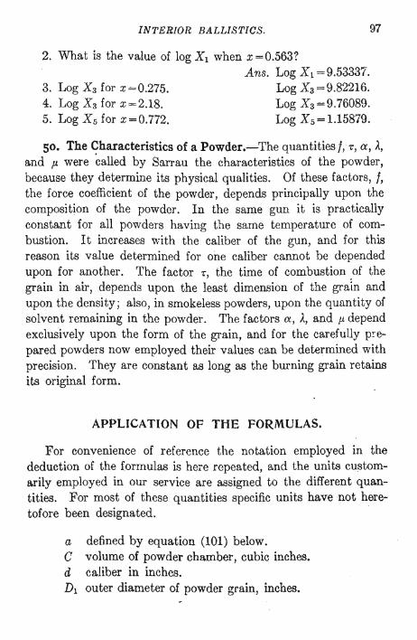
INTERIOR BALLISTICS. 97
2. What is the value of log Xl when x=0.563?
3. Log Xa for x= 0.275. 4. Log Xa for x=2.18. 5. Log Xs for x=0.772.
Ans. Log Xl =9.53337. Log Xa=9.82216. Log Xa=9.76089. Log X s=1.15879.
50. The Characteristics of a Powder.-The quantities I, -., a, A, and p. were called by Sarrau the characteristics of the powder, because they determine its physical qualities. Of these factors, I, the force coefficient of the powder, depends principally upon the composition of the powder. In the same gun it is practically constant for all powders having the same temperature of combustion. It increases with the caliber of the gun, and for this reason its value determined for one caliber cannot be depended upon for another. The factor -., the time of combustion of the grain in air, depends upon the least dimension of the grain and upon the density; also, in smokeless powders, upon the quantity of solvent remaining in the powder. The factors a, A, and p. depend exclusively upon the form of the grain, and for the carefully p!"epared powders now employed their values can be determined with precision. They are constant as long as the burning grain retains its original form.
APPLICATION OF THE FORMULAS.
For convenience of reference the notation employed in the deduction of the formulas is here repeated, and the units customa.rily employed in our service are assigned to the different quantities. For most of these quantities specific units have not heretofore been designated.
a defined by equation (101) below. C volume of powder chamber, cubic inches. d caliber in inches. Dl outer diameter of powder grain, inches.

98 ORDNANCE AND GUNNERY.
d1 diameter of perforation of powder grain, inches. j force coefficient of the powder, pounds per square inch. F fraction of grain burned. g acceleration due to gravity, 32.16 foot-seconds. k=y/w, fraction of charge burned. I thickness of layer burned at any instant, inches. 10 one half least dimension of grain, inches. L constant logarithms in the ballistic equations. m length of powder grain, inches. M ballistic velocity constant, foot-seconds. M' ballistic pressure constant, pounds per square inch. N, N' ballistic constants. n number of powder grains in one pound. pI ballistic pressure constant, pounds per square inch . . p pressure while powder burns, pounds per square inch. pa pressure after powder is burned. pounds per square inch. pm maximum pressure, pounds per square inch. po standard atmospheric pressure, 14.6967 Ibs. per square
inch. S1 initial surface of a pound of powd~r, square inches. 1./, travel of projectile, inches. U total travel of projectile, inches. v velocity of projectile while powder burns, foot-seconds. Va velocity of projectile after powder is burned, foot-sees. V muzzle velocity of projectile, foot-seconds. V1 ballistic constant, velocity at infinity, foot-seconds. Vc velocity of combustion of powder, foot-seconds. Vo specific volume of a gas, cubic feet. Vo initial volume of a powder grain, cubic inch!)s. w weight of projectile, pounds. x number of expansions of volume of initial air space. Xo, Xl, X 2, X 3 , X 4 , X 5 , functions of x. y weight of powder burned at any instant, pounds. Zo reduced length of initial air space, inches.

INTERIOR BALLISTICS.
~ 1 constants of form of powder grain.
./} density of powder. J density of loading. w weight of powder charge, pounds. 'r time of burning of whole grain in air, seconds_. w cross section of bore, square inches.
99
Quantities topped with a bar, as V, X, U, X 2 , etc., designate the particular values of the quantities at the instant of complete burning of the powder charge.
With the units assigned above the following working equations are, with the aid of equation (28), derived from the equations whose numbers appear on the left. The numbers in brackets are the logarithms of the numerical constants after reduction to the proper units.
(22) J = [1.44217]w /e (100)
(27) /}-J
(101) a=--J/J
(29) Zo = [1.54708]aw/ d2 (102)
(57) x=u/zo (103)
(73) v2 =[4.44383] f X2W/W (104)
(85) M' = [3.82867]Mw/ aw (105)
(87) P' = [3.35155]V12w/aw (106)
(89) P' = [1. 79538] f / a (107)
(97) 'r = [2.56006] / ;;;;;QXo/d2 (108)
(98) t=[5.55617]V12W / w (109)

100 ORDNANCE AND GUNNElf,Y.
In addition to the above working equations the following formulas are needed or are useful in the solution of most problems.
(74) M =a.1j2 / X 1 N=).. / X o N'=p./ X 02 (110)
(95) M=aV12/ X o (111)
(75) v2=MXl I1+NXo+N'Xo2} (112)
(86) p=M'X3 11+NX4+N'Xsl (113)
(78) va2= V12X2 (114)
(88) p'
(115) Pa= (l+ x)t
(80) k=Y/ iiJ = V2/ V12X2 (116)
vc=~(-1!) it .. po (123)
l=loXo/ Xo (124)
1=/0(:) t (137)
(iiJ) \W)f 1 = 10iiJo Wo (138)
51. Transformation of the Formulas into the Forms (104) to (109).-In the deduction of the formulas the quantities have been expressed in general terms, no units having been assigned.
In assigning now to the velocity v the foot-second unit and to the weights the pound unit, we fix the units in the formulas as the foot, the pound, and the second. All dimensional quantities in the formulas must then be considered as expressed in feet, square feet, or cubic feet; pressures in pounds per square foot, and time in seconds. As appears on page 98,we intend now to pre-
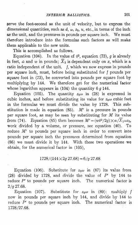
INTERIOR BALLISTICS. 101
serve the foot-second as the unit of velocity, but to express the dimensional quantities, such as d, w, Zo, u, etc., in terms of the inch rul the unit, and the pressures in pounds per square inch. We must therefore introduce into the formulas such factors as will make them applicable to the new units.
This is accomplished as follows. Equation (104). In the value of v2, equation (73), 9 is already
in feet, ciJ and w in pounds; X 2 is dependent only on x, which is a ratio independent of the unit. I, which we now express in pounds per square inch, must, before being substituted for I pounds per square foot in (73), be converted into pounds per square foot by mUltiplying by 144. We therefore get for the numerical factor whose logarithm appears in (104) the quantity 6 9 144.
Equation (105). The quantity ZoW in (28) is expressed in cubic inches, and before substituting its value for ZoW cubic feet in the formulas we must divide the value by 1728. This substitution is made in equation (85). M' is a pressure in pounds per square foot, as may be seen by substituting "for M its value from (74) . Equation (85) then becomes M'= (w1j2/ 2g)Xa/ X1wzo, work divided by a volume, or pressure, see equation (40). To reduce M' to pounds per " square inch in order to convert into pounds per square inch the pressures determined from equation (86) we must divide it by 144. With these two operations 'we obtain, for the numerical factor in (105),
1728/(144 x2g 27.68) =6/ g 27.68
Equation (106). Substitute for ZoW in (87) its value from (28) divided by 1728, and divide the value of pI by 144 to reduce pI to pounds per square inch. The numerical factor is 2/ g 27.68.
Equation (107). Substitute for " zow in (89); multiply I now in pounds per square inch by 144, and divide by 144 to reduce ' pI to pounds per square inch. The numerical factor is 1728/27.68.

102 ORDNANCE AND GUNNERY.
Equation (108). From (97), multiplying and dividing b) ai. '( 27.68aw) t
w 1728 _ 't'= t nd2 /4X o
(6gPo144) 144
The numerical factor becomes
, Equation (109). Reduce (98) to pounds per square inch by dividing by 144. The numerical factor is 1/ 6g 144.
DETERMINATION OF THE BALLISTIC FORMULAS FROM MEASURED INTERIOR VELOCITIES.
52. As a test of the formulas that have been determined, and at the same time to illustrate their extensive use, we will follow Colonel Ingalls in his application of these formulas to the experiments made by Sir Andrew Noble in 1894 with a six-inch gun. The normal length of the gun was 40 calibers, but it could be lengthened as desired to 50, 75, or 100 calibers.
The length of a gun when expressed in calibers ordinarily means the length measured from the front face of the closed breech block to the muzzle of the gun. The travel of the projectile is the distance passed over by the base of the projectile, measured from its position in the gun when loaded. The length of the gun in calibers is therefore equal to the travel of the projectile plus the length of the powder chamber.
By means of a chronoscope not differing in principle from the Schultz chronoscope that has been described, the velocity of the shot could be measured at sixteen points in the bore. Noble gives the mean instrumental error of. the chronoscope as three onemillionths of a second.
Problem I.-A 100-pound projectile was fired from this 6-inch gun with a charge of 27t lbs.of cordite. Diameter of grain 0".1,
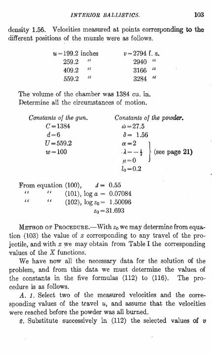
INTERIOR BALLISTICS. 103
density 1.56. Velocities measured at points corresponding to the different positions of the muzzle were as follows.
u=199.2 inches 259.2 " 409.2 " 559.2 "
v=2794 f. s. 2940 " 3166 " 3284 "
The volume of the chamber was 1384 cu. in. Determine all the circumstances of motion.
Constants of the gun. C =1384 d=6
U =559.2 w=100
Constants of the powder. w=27.5 3= 1.56
a=2 ) ,). = - ! (see page 21) ,u=0 lo=0.2
From equation (100), J = 0.55 " " (101), log a = 0.07084 " " (102), log Zo = 1.50096
zo=31.693
METHOD OF PROCEDURE.-With Zo we may determine from equation (103) the value of x corresponding to any travel of the projectile, and with x:we may obtain from Table I the corresponding values of the X functions.
We have now all the necessary data for the solution of the problem, and from this data we must determine the values of the constants in the five formulas (112) to (116). The procedure is as follows.
A. 1. Select two of the measured velocities and the corresponding values of the travel u, and assume that the velocities were reached before the powder was all burned.
2. Substitute successively in (112) the selected values of v

104 ORDN ANCE AND GUNNERY.
with the values of the X functions obtained with the corresponding travels.
We have thentwo equations in which only the constants are unknown. As N' is a function of N, there are but two constants, M and N, to be determined from the two equations.
3. Determine M and N from the two equations. 4. With the value of N find from the second of equations (110)
the value of Xo, and with this determine from the table the value of x, and from (103) the value of ii.
5. The powder was all burned at this travel ii, and if the values of u corresponding to the selected veiocities are less than u, we were right in assuming these two velocities as having been reached before the powder was all burned.
Our determinations of M and N are therefore correct, and, as explained on page 91, all the other constants may be determined from these two.
53. B. If, however, one or both of the selected velocities were reached at a travel greater than ii, our assumption that they were both reached before the powder was burned was wrQng and our values of M, N, -and ii obtained under that assumption are wrong.
We must therefore determine new values of M and N as follows.
Substitute the first of the selected velocities with the corresponding values of the X functions in (112) as before. Substitute the second selected velocity in (114) with the value of X 2
corresponding to the travel. Detetmine V 1 •
. Replace N, N', and M in (112) by their values from (110) and (111). Then in (112) Xo is the only unknown quantity, and its value can be determined.
With X'o and V 1 the values of M and N are readily found.
C. The constants cannot be determined if both the selected velocities were reached after the powder was wholly burned.