a test harness for a control software
TRANSCRIPT

A TEST HARNESS FOR A CONTROL SOFTWARE
by
JOSEPH CHUKWUDI OKIKA, LOKESH SIDDALINGAIAH
MASTERS THESIS
Presented to the Faculty of Engineering and Science
Aalborg University
Department of Computer Science
AALBORG UNIVERSITY
June 2005

A TEST HARNESS FOR A CONTROL SOFTWARE
Department of Computer Science
Date:
Joseph Chukwudi Okika
Lokesh Siddalingaiah
ii

to our
FAMILIES
with love
iii

Acknowledgements
We wish to express thanks to our supervisor Professor Anders P. Ravn for his guidance and
advice.
We would also like to thank Engineer Jean of Alphashipmate for providing us with informa-
tion the working of an Electronic Control Unit and a marine diesel engine. Our appreciation
also goes to Mr Vesa-Matti Puro of OpenTTCN for providing us with the OpenTTCN tool.
iv

Abstract
The thesis presents the overall activities involved in model based development of a test har-
ness for a control software. This is illustrated by a case study on the Alpha Shipmate control
software for an Electronic Control Unit of a Marine Diesel Engine.
The development of the test harness includes study and use of Object Oriented Analysis
and a Model Based Design Approach. The development uses UML as supported by the
Rhapsody tool. We also employ some design patterns at the design phase.
The test harness supports executing test scripts using Testing and Test Control Notation
version 3 (TTCN-3). It has a Java GUI which is interfaced with engine control functions
through Java Native Interfaces (JNI).
v

Table of Contents
List of Figures . . . . . . . . . . . . . . . . . . . . . . . . . . . . . . . . . . . . . . . ix
Chapter Page
1 Introduction . . . . . . . . . . . . . . . . . . . . . . . . . . . . . . . . . . . . . . . 1
1.1 Objectives . . . . . . . . . . . . . . . . . . . . . . . . . . . . . . . . . . . . . 5
1.2 Expected Result . . . . . . . . . . . . . . . . . . . . . . . . . . . . . . . . . . 6
1.3 Related Work . . . . . . . . . . . . . . . . . . . . . . . . . . . . . . . . . . . 7
1.3.1 Engine Models . . . . . . . . . . . . . . . . . . . . . . . . . . . . . . 7
1.3.2 Test Harness . . . . . . . . . . . . . . . . . . . . . . . . . . . . . . . 9
1.3.3 Summary . . . . . . . . . . . . . . . . . . . . . . . . . . . . . . . . . 11
1.4 Overview . . . . . . . . . . . . . . . . . . . . . . . . . . . . . . . . . . . . . . 11
2 Object Oriented Analysis (OOA) . . . . . . . . . . . . . . . . . . . . . . . . . . . 12
2.1 Problem Domain Analysis . . . . . . . . . . . . . . . . . . . . . . . . . . . . 13
2.1.1 Context . . . . . . . . . . . . . . . . . . . . . . . . . . . . . . . . . . 14
2.1.2 The FACTOR criteria . . . . . . . . . . . . . . . . . . . . . . . . . . 14
2.1.3 System Definition . . . . . . . . . . . . . . . . . . . . . . . . . . . . . 15
2.1.4 Problem Domain Model . . . . . . . . . . . . . . . . . . . . . . . . . 15
2.2 Application Domain Analysis . . . . . . . . . . . . . . . . . . . . . . . . . . 16
2.2.1 Usage . . . . . . . . . . . . . . . . . . . . . . . . . . . . . . . . . . . 16
2.2.2 Interfaces . . . . . . . . . . . . . . . . . . . . . . . . . . . . . . . . . 17
3 System Design and Implementation . . . . . . . . . . . . . . . . . . . . . . . . . . 19
3.1 Model Based Development . . . . . . . . . . . . . . . . . . . . . . . . . . . . 19
3.2 Extreme Model Based Development . . . . . . . . . . . . . . . . . . . . . . . 20
3.3 Software Patterns . . . . . . . . . . . . . . . . . . . . . . . . . . . . . . . . . 22
3.3.1 Architecture Patterns . . . . . . . . . . . . . . . . . . . . . . . . . . . 22
3.3.2 Design Patterns . . . . . . . . . . . . . . . . . . . . . . . . . . . . . . 23
vi

3.4 Architecture . . . . . . . . . . . . . . . . . . . . . . . . . . . . . . . . . . . . 23
3.4.1 Components . . . . . . . . . . . . . . . . . . . . . . . . . . . . . . . . 25
3.5 Detailed Design . . . . . . . . . . . . . . . . . . . . . . . . . . . . . . . . . . 29
3.5.1 GUI . . . . . . . . . . . . . . . . . . . . . . . . . . . . . . . . . . . . 29
3.5.2 ECU . . . . . . . . . . . . . . . . . . . . . . . . . . . . . . . . . . . . 33
4 Testing . . . . . . . . . . . . . . . . . . . . . . . . . . . . . . . . . . . . . . . . . . 35
4.1 TTCN-3 Test System . . . . . . . . . . . . . . . . . . . . . . . . . . . . . . . 35
4.2 TTCN-3 Syntax . . . . . . . . . . . . . . . . . . . . . . . . . . . . . . . . . . 37
4.2.1 Basic language elements . . . . . . . . . . . . . . . . . . . . . . . . . 38
4.2.2 Test System Interfaces . . . . . . . . . . . . . . . . . . . . . . . . . . 45
5 Experiments . . . . . . . . . . . . . . . . . . . . . . . . . . . . . . . . . . . . . . . 50
5.1 Using The System . . . . . . . . . . . . . . . . . . . . . . . . . . . . . . . . . 50
5.1.1 Installation . . . . . . . . . . . . . . . . . . . . . . . . . . . . . . . . 50
5.1.2 Writing Test Scripts . . . . . . . . . . . . . . . . . . . . . . . . . . . 52
5.1.3 Running Test Scripts . . . . . . . . . . . . . . . . . . . . . . . . . . . 53
5.1.4 Using The Engine Simulator . . . . . . . . . . . . . . . . . . . . . . . 54
5.2 Example . . . . . . . . . . . . . . . . . . . . . . . . . . . . . . . . . . . . . . 56
6 Conclusion . . . . . . . . . . . . . . . . . . . . . . . . . . . . . . . . . . . . . . . . 60
6.1 Use of Model Based Development . . . . . . . . . . . . . . . . . . . . . . . . 60
6.1.1 Analysis . . . . . . . . . . . . . . . . . . . . . . . . . . . . . . . . . . 60
6.1.2 Design . . . . . . . . . . . . . . . . . . . . . . . . . . . . . . . . . . . 61
6.1.3 Summary . . . . . . . . . . . . . . . . . . . . . . . . . . . . . . . . . 62
6.2 Development of A Test Harness . . . . . . . . . . . . . . . . . . . . . . . . . 63
6.2.1 TTCN-3 . . . . . . . . . . . . . . . . . . . . . . . . . . . . . . . . . . 63
6.3 Further Work . . . . . . . . . . . . . . . . . . . . . . . . . . . . . . . . . . . 64
6.4 Summary . . . . . . . . . . . . . . . . . . . . . . . . . . . . . . . . . . . . . 65
References . . . . . . . . . . . . . . . . . . . . . . . . . . . . . . . . . . . . . . . . . . 66
Appendix
vii

A Overview of the CD-ROM . . . . . . . . . . . . . . . . . . . . . . . . . . . . . . . 69
B IDL Summary . . . . . . . . . . . . . . . . . . . . . . . . . . . . . . . . . . . . . . 70
viii

List of Figures
1.1 Marine Diesel Engine . . . . . . . . . . . . . . . . . . . . . . . . . . . . . . . 1
1.2 Structure of an Electronic Control Unit . . . . . . . . . . . . . . . . . . . . . 2
1.3 Manual Test Procedure . . . . . . . . . . . . . . . . . . . . . . . . . . . . . . 3
1.4 Object Diagram . . . . . . . . . . . . . . . . . . . . . . . . . . . . . . . . . . 4
1.5 Generic Test Harness . . . . . . . . . . . . . . . . . . . . . . . . . . . . . . . 5
1.6 Conceptual Setup . . . . . . . . . . . . . . . . . . . . . . . . . . . . . . . . . 6
2.1 Object Oriented Analysis and Design[19] . . . . . . . . . . . . . . . . . . . . 13
2.2 Rich Picture . . . . . . . . . . . . . . . . . . . . . . . . . . . . . . . . . . . . 14
2.3 Overview of the Test Harness Classes . . . . . . . . . . . . . . . . . . . . . . 16
2.4 Use Case Diagram of the Test Harness . . . . . . . . . . . . . . . . . . . . . 17
3.1 Layered Component Architecture for a test harness . . . . . . . . . . . . . . 25
3.2 GUI Component . . . . . . . . . . . . . . . . . . . . . . . . . . . . . . . . . 26
3.3 TTCN-3 Component . . . . . . . . . . . . . . . . . . . . . . . . . . . . . . . 27
3.4 ECSoftware Component . . . . . . . . . . . . . . . . . . . . . . . . . . . . . 28
3.5 Test Harness User Interface . . . . . . . . . . . . . . . . . . . . . . . . . . . 30
4.1 TTCN-3 Architecture . . . . . . . . . . . . . . . . . . . . . . . . . . . . . . . 35
4.2 TTCN-3 Extended BCNF metanotation for TTCN-3 . . . . . . . . . . . . . 37
4.3 The Overview of TTCN-3 Module . . . . . . . . . . . . . . . . . . . . . . . . 38
4.4 List of datatypes in TTCN-3 . . . . . . . . . . . . . . . . . . . . . . . . . . . 41
4.5 Conceptual view of a TTCN-3 test configuration . . . . . . . . . . . . . . . . 42
4.6 General Structure of a TTCN-3 Test System [12] . . . . . . . . . . . . . . . 45
4.7 Conceptual view of a TTCN-3 test configuration . . . . . . . . . . . . . . . . 48
5.1 Test Harness Window . . . . . . . . . . . . . . . . . . . . . . . . . . . . . . . 53
ix

5.2 Engine Simulator Window . . . . . . . . . . . . . . . . . . . . . . . . . . . . 55
5.3 Example System Under Test . . . . . . . . . . . . . . . . . . . . . . . . . . . 56
5.4 Example System Under Test Adapter . . . . . . . . . . . . . . . . . . . . . . 57
x

Listings
3.1 Start Operation code fragment . . . . . . . . . . . . . . . . . . . . . . . . . . 30
3.2 Run Operation code fragment . . . . . . . . . . . . . . . . . . . . . . . . . . 31
3.3 Start Tester Operation code fragment . . . . . . . . . . . . . . . . . . . . . . 31
3.4 Set Script Operation code fragment . . . . . . . . . . . . . . . . . . . . . . . 32
3.5 Run Test Operation code fragment . . . . . . . . . . . . . . . . . . . . . . . 32
3.6 ECU code fragment . . . . . . . . . . . . . . . . . . . . . . . . . . . . . . . . 33
4.1 TTCN-3 BNF . . . . . . . . . . . . . . . . . . . . . . . . . . . . . . . . . . . 37
4.2 TTCN-3 Module . . . . . . . . . . . . . . . . . . . . . . . . . . . . . . . . . 39
4.3 TTCN-3 Module Parameter . . . . . . . . . . . . . . . . . . . . . . . . . . . 39
4.4 Structured Types . . . . . . . . . . . . . . . . . . . . . . . . . . . . . . . . . 41
4.5 Test Case . . . . . . . . . . . . . . . . . . . . . . . . . . . . . . . . . . . . . 42
4.6 Test Component . . . . . . . . . . . . . . . . . . . . . . . . . . . . . . . . . 43
4.7 Port Definition . . . . . . . . . . . . . . . . . . . . . . . . . . . . . . . . . . 43
4.8 altstep Definition . . . . . . . . . . . . . . . . . . . . . . . . . . . . . . . . . 44
4.9 TCI . . . . . . . . . . . . . . . . . . . . . . . . . . . . . . . . . . . . . . . . 46
4.10 TCI-CH . . . . . . . . . . . . . . . . . . . . . . . . . . . . . . . . . . . . . . 46
4.11 TCI-CD . . . . . . . . . . . . . . . . . . . . . . . . . . . . . . . . . . . . . . 47
4.12 TCI-TL . . . . . . . . . . . . . . . . . . . . . . . . . . . . . . . . . . . . . . 47
4.13 Send Operation . . . . . . . . . . . . . . . . . . . . . . . . . . . . . . . . . . 48
4.14 TRI function . . . . . . . . . . . . . . . . . . . . . . . . . . . . . . . . . . . 48
5.1 Test Result . . . . . . . . . . . . . . . . . . . . . . . . . . . . . . . . . . . . 57
5.2 Test Result Continued.. . . . . . . . . . . . . . . . . . . . . . . . . . . . . . . 57
5.3 Test Result Continued.. . . . . . . . . . . . . . . . . . . . . . . . . . . . . . . 58
B.1 TTCN-3 BNF . . . . . . . . . . . . . . . . . . . . . . . . . . . . . . . . . . . 70
xi

Chapter 1
Introduction
In this thesis, we are dealing with a test harness for an embedded software provided by
Alpha Shipmate Development - a Research and Development department of MAN B&W
Diesel A/S which is a leading supplier of large diesel engines for ship propulsion systems,
stationary power supply and rail traction. The Group is also one of the leading suppliers of
diesel power plants and turbochargers.
A Marine Diesel Engine is composed of several parts ranging from mechanical, electrical to
electronic.
1.1.
Figure 1.1: Marine Diesel Engine
All these are connected together to form the complete engine which can be controlled re-
motely from the control room or through a bridge (knobs that are adjusted manually).
1

In recent years, the working of a marine diesel engine is controlled using electronic control
unit (ECU), which is also known as an engine management system. This is an electronic
device, basically computers, and some networks that reads several sensors and uses the in-
formation to control the actuators for example fuel injection in a diesel engine. The ECU
allows an engine‘s operation to be controlled in a great detail, allowing greater fuel efficiency,
better power and responsiveness, and much lower pollution levels than earlier generations of
engines [20].
The Electronic Control Unit consists of several units connected together through a system
bus which is physically replicated as shown in Figure 1.2
Figure 1.2: Structure of an Electronic Control Unit
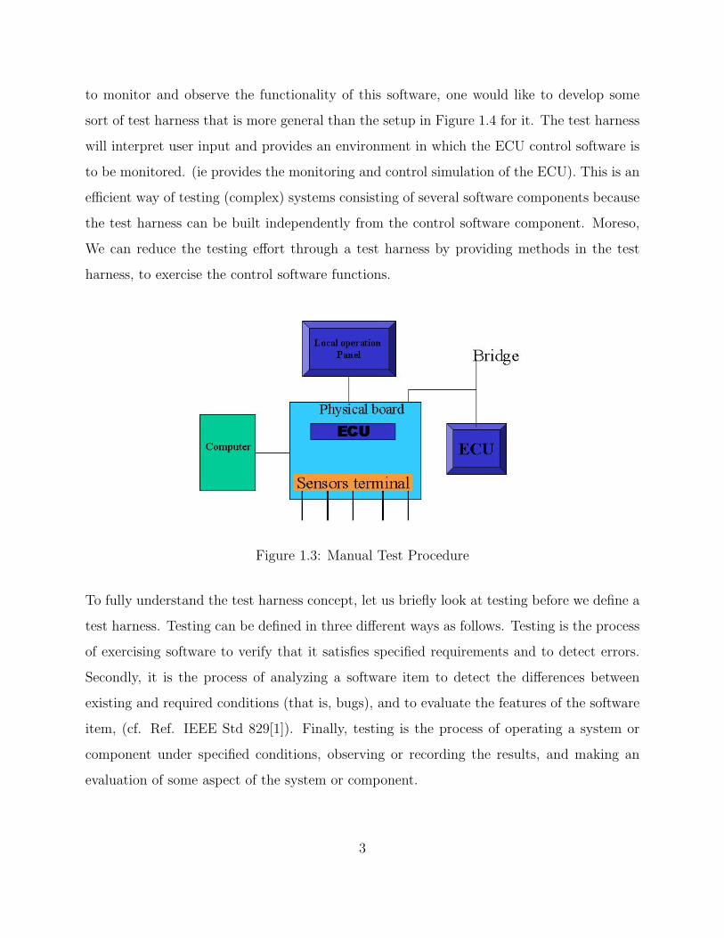
The manual test procedure for an ECU is done by the connections as shown in Figure 1.3.
The physical board of the ECU is connected to a computer terminal through the use of
modbus [4]. During operation, input data in text format is passed to the ECU and changes
are converted back to comma separated text format. There is also a connection to the bridge
for remote operations.
Embedded software is a software that is part of a larger system and performs some of the
functions of that system. The ECU is a typical embedded software
In Figure 1.4, an object diagram of the complete ECU control software is shown. Looking
at the figure, one can immediately see the complex nature of the software. The small blocks
(ie. rectangles) shown in the diagram are the different objects in the ECU control software
depending on each other (the arrows) to fulfil the overall functionality of the system. In order
2
to monitor and observe the functionality of this software, one would like to develop some
sort of test harness that is more general than the setup in Figure 1.4 for it. The test harness
will interpret user input and provides an environment in which the ECU control software is
to be monitored. (ie provides the monitoring and control simulation of the ECU). This is an
efficient way of testing (complex) systems consisting of several software components because
the test harness can be built independently from the control software component. Moreso,
We can reduce the testing effort through a test harness by providing methods in the test
harness, to exercise the control software functions.
Figure 1.3: Manual Test Procedure
To fully understand the test harness concept, let us briefly look at testing before we define a
test harness. Testing can be defined in three different ways as follows. Testing is the process
of exercising software to verify that it satisfies specified requirements and to detect errors.
Secondly, it is the process of analyzing a software item to detect the differences between
existing and required conditions (that is, bugs), and to evaluate the features of the software
item, (cf. Ref. IEEE Std 829[1]). Finally, testing is the process of operating a system or
component under specified conditions, observing or recording the results, and making an
evaluation of some aspect of the system or component.
3

Figure 1.4: Object Diagram
In this thesis, we are focusing on testing according to the third definition which includes
creating specifications of test cases (a set of inputs, execution preconditions, and expected
outcomes developed for a particular objective) or test suites (a collection of tests). Specifi-
cation of a test is done through a test script which is the instructions for a particular test
that will be carried out by an automated test tool.
A test harness is a program which sets up an environment (software environment in which
tests will be run, and any other software with which the software under test interacts when
under test) and calls a test case (a set of inputs, execution preconditions, and expected
outcomes developed for a particular objective).
A test harness collects tests into suites and provides an environment for them to be run as
a batch and the results are displayed or stored for future reference. A generic test harness
found in [25] is termed ”Test::Harness” which run ”Perl” standard test scripts and give re-
sult. For instance, when a test suite is run using the test harness, a sample summary report
shown in Figure 1.5 is displayed.
Thus the summary report shows that everything passed but t/waterloo.t.
4

Figure 1.5: Generic Test Harness
1.1 Objectives
The objectives of this thesis are as follows:
• Discuss the use of Object Oriented Analysis and a Model Based Design Approach.
• Develop a test harness for the Engine Control Software.
• Develop an Engine Simulation through a Java GUI.
and we follow the criteria mentioned below:
Functionality: A Test Harness for any control software.
Application Domain: Monitoring of the control software and demonstration.
Conditions: The harness should be able to provide a log/view of the working of the control
software.
Technology: The hardware used for this project is Windows-based computers, Java, C++,
C and a Unified Modeling Language (UML) [14] based CASE tool - Rhapsody [24]. Full
production-quality C code, including underlying architecture, behavior characteristics, and
real-time framework, can then be generated directly from the designdiagrams [24]. We also
5

used Testing and Test Control Notation version 3 - TTCN-3 [12, 27] for generating and
executing the test scripts.
Objects: Electronic Control Unit of the engine (the Alpha C module), Test Harness and
a Global a data structure.
Approach: We shall be using a model-based approach to design and implement the test
harness with additional features from Extreme Programming [26] through an Object Oriented
Analysis and Design process [19].
The setup as shown in Figure 1.6 consists of three objects as noted above; a test harness
consisting of a set and a get methods which we named Probe and Generator respectively
all embodied in a Java based Graphical User Interface. The test harness is interfaced with
the ECU consisting of the control functions and the GlobalIO data structure containing the
various values of the engine variables.
Figure 1.6: Conceptual Setup
1.2 Expected Result
In line with the above explanations, we will develop a test harness for the control software
case study. The means for developing the test harness and experiments for the test harness
is also presented.
6

1.3 Related Work
In this section we look at different engine models and their usefulness for generating test
scripts for the Harness as developed by others. We also look at various work on using TTCN-
3 as a test.
1.3.1 Engine Models
In [28], Yihuai Hu et al. developed a simulator to take care of the behavior of a container ship
under different performance faults and different running conditions. They introduced math-
ematical models of the main diesel engine including chamber combustion model, variable
injection timing model and hull-propeller-engine model. A real time simulation algorithm
is described to meet the demands of rapid response, long running duration and little error
accumulation of the simulator. Typical performance failures, structural faults and boundary
conditions of main engine were simulated. This work will help us the generation of tests.
The model of the diesel engine in [28] is of a dynamical systems model. They referred to it as
a general- purpose engine thermodynamic simulation code. The model is a control volume
type which means that it defines the boundaries of the combustion chamber in the area of the
inlet and exhaust valves. This treats a multi-cylinder engine as a series of thermodynamic
control volumes interconnected through valves and ports.
As regards to testing, they had fault models where they classified the main engine faults as
malfunctions, structural faults, abnormal boundary conditions. The faults are checked by
self-testing the software function with standard data file.
A sequel to the above work is a PC-based diagnostic simulator [18] which takes in user input
values for the diagnosis and maintenance of a marine diesel engine is developed. It focused
7

on teaching knowledge of engine operations, especially how load and other conditions affect
engine parameters; watch keeping; fault recognition; breakdowns; and other relationship be-
tween engine technical state and maintenance actions. The model of the engine in [18] is
more of the physical engine.
The model of the engine designed in MATLAB by David Houdyschell [10] concentrated on
a Diesel linear engine prototype developed for electrical power generation. The operation of
the linear engine is different from the conventional mechanism of diesel engine because the
engine is made of two opposed pistons connected by a link rod. The pistons are also made
to have equal symmetric strokes(that is upward and downward movement). Similar to some
of the work mentioned, there is no consideration of the sensors and actuators as well as a
control software.
Kyrtatos et al [22] developed a model of a marine diesel engine powered plant is which meant
to be used for performance prediction as well as for control and optimization purposes. Based
on simulation results using the ”virtual powerplants” code, a simpler transfer-function type
model was developed and then utilized to design an improved engine speed controller. This
novel speed controller is used back into the ”virtual powerplants” code and the predictions
showed improvements in the transient performance of the powerplants. Though there is the
speed governor which is used for the control of the fuel rack position which determines the
fuel injected into the engine cylinders, it is all based on PI control law.
R. Iserman et al [23] modeled a Hardware-In-the-Loop simulation of combustion engines.
They used the model to make comparisons between real-time simulations and measurements
on real diesel engines and trucks. Their main focus was to develop new control algorithms
and to investigate the effect of faults, both in sensors and actuators as well as the engine.
They considered different methods for the models such as theoretical modeling and experi-
mental or identification modeling. ”Theoretical modeling is based on physical laws, expressed
8

by equations.” [23]. In experimental modeling, input and output signals are measured for
selected class of models which is adapted to the process behavior. LOLIMOT an artificial
neural network was used to model the exhaust turbocharger.
1.3.2 Test Harness
As mentioned above, we have chosen TTCN-3 as the language used for writing the test scripts
in our thesis. Testing and Test Control Notation version 3 (TTCN-3) is a standardized test
specification and test implementation language which is extended from previous versions of
TTCN called Tree and Tabular Combined Notation. For further details see [13].
TTCN-3 is applied in all kinds of black box testing for both reactive and distributed system.
Notable examples are Telecom systems, mobile systems, Internet, CORBA etc. TTCN-
3 enables systematic, specification-based testing for various kinds of tests including e.g.
functional, scalability, load, interoperability, robustness, regression, system and integration
testing. We are concentrating on black box testing as we are testing the legacy code. In the
following sections we present TTCN-3 architecture and its language syntax.
We chose TTCN-3 for our thesis because it has a well defined syntax, static, and operational
semantics and a powerful core notation which can be linked with UML Testing Profile ( a
language for designing, visualizing, specifying, analyzing, constructing and documenting the
artifacts of test systems [11]).
Moreso, it is based on series of standards which means that it cannot die soon. Notable
standards are enumerated in [12].The 3rd point is that the control software has a communi-
cation nature between the components that fits into TTCN-3 semantics.
TTCN-3 has been in full use in the telecommunication sector for conformance testing. As
9

the it has been extended to cover more areas of software development and testing, we look
at some of the related work in the following paragraphs.
Testing of an Automatic Teller Machine (ATM) was developed by Jens Grabowski and oth-
ers in [15]. They viewed an ATM as a computer, which is connected with a bank database
and ATM hardware. The connections among these components are realized by a hardware
interface and a network interface. The ATM system allows a customer to withdraw money
from his account. The ATM hardware gives a customer access to the ATM system. The
bank database is needed to check and update the credit balance of a customer.
They considered a complete and successful money withdrawal and abstracted from the hard-
ware interactions like putting the credit card into the ATM hardware, typing the PIN number
or delivering money, by modeling such interactions in form of messages. The withdrawal of
money starts with the authentication of the customer. The customer puts the card into the
ATM hardware, the ATM hardware reads the card data, collects the PIN number from the
customer and transmits both to the ATM. The ATM decodes the card data, verifies the PIN
number against the decoded card data and returns the result of this verification to the ATM
hardware Afterwards, the customer is connected and sends a withdrawal request together
with the amount to be withdrawn to the ATM. The ATM debits the account identified by
the card and the PIN number in the bank database and the bank database acknowledges
the successful debit operation.
The above work is useful to us as it gives an insight on how to write the scripts of a system
consisting of both hardware and software while abstracting from certain hardware interac-
tions.
10

1.3.3 Summary
However, in the above mentioned cases, the objective has been either to model the mechanical
aspect of the Engine or simulate the operating of the engine. This is useful to us as it provides
an insight on how to model heterogeneous systems and on the hand gives an idea on how to
write test scripts. Though several developers/people have tried modeling a diesel engine, we
have neither found a model of the control software nor of a test harness but surely some test
harness for other systems. In this thesis, we are concerned with a test harness of a control
software through model based development.
1.4 Overview
In Chapter 2 the methods and tools used in the development of the system are introduced.
The approach to follow while using these methods is also examined with examples. In
Chapter 3 the design of the test harness is discussed in terms of its components and it
continues with the detailed design of the components. The interfaces between the different
components are also explained. In Chapter 4, the overview of TTCN-3 as used in the thesis
is given coupled with examples of different entities of TTCN-3. Experiments and how to
setup the Test Harness together with a guide on how to run the test scripts is presented in
Chapter 5, and finally conclusion of the thesis is Chapter 6.
11

Chapter 2
Object Oriented Analysis (OOA)
In this Chapter, we present the analysis of the ”Test Harness” under two sections - Problem
Domain Analysis and Application Domain Analysis.
Developing software systems for embedded system is challenging because of its complexity
as it consists of several components integrated together to form the overall system. Devel-
opment of a test harness for this kind of software is needed for the success of modern diesel
engines. We therefore need a well structured development method that will break down the
complexity and support reuse of components at various phases of development. We adopt
Object Oriented Analysis and Design method and model based development supported by
case tools.
Object Oriented Analysis provides the process for the development of software applications.
It involves four main activities. We followed the division of these activities in [19] for the
development of a test harness of the engine control software. Itemized below are the activities
which is also shown diagrammatically in figure 2.1 but we focus on Problem and Application
Domain Analysis in this Chapter;
• Problem Domain Analysis
• Application Domain Analysis
• Architectural Design
• Component Design
12

Figure 2.1: Object Oriented Analysis and Design[19]
2.1 Problem Domain Analysis
In Problem Domain Analysis, we give the details of the activities involved at the early stage
of the project. This is coined in one word, analysis. Analysis is an activity in which some
item is taken apart and described [19]. We have basically two kinds of analysis, namely,
problem domain analysis and application domain analysis. In problem domain analysis, we
focus on gathering all the information on what the system should deal with. Where as our
main concern in application domain analysis is on the use of the system.
The problem domain is the part of a context that is controlled or monitored by a system,
and analysis concentrates on what the system should deal with. The following subsections
describe what is involved in this analysis phase.
13

Figure 2.2: Rich Picture
2.1.1 Context
In context, we introduced a rich picture which is an informal drawing that presents the
illustrators understanding of a situation. It focuses on important aspects of the situation.
In figure 2.2, we show a rich picture that we came up with at the initial phase of the project.
2.1.2 The FACTOR criteria
The FACTOR criterion is a term used in [19] for system definitions. Each of the six letters
refers to a key element in system definition. Itemized below are the definitions of the elements
and its relationship to the test harness system.
Functionality: This is the system functions that support the application-domain tasks.
Regarding the thesis, the functionality is a Test Harness for any control software.
Application Domain: Concerns those parts of an organization that administrate, mon-
itor, or control a problem domain. Monitoring of the control software and demonstration
covers the application domain of the test harness system.
Conditions: Takes care of the conditions under which the system will be developed and
used. One of the conditions in the test harness system is that the Test Harness should be
able to provide a view of the working of the control software.
14

Technology: This defines both the technology used to develop the system and the technol-
ogy on which the system will be run. The hardware used for this project is Windows-based
computers and the software is Rhapsody in C. The Rhapsody Visual Programming Environ-
ment (VPE) enables software engineers to graphically design real-time embedded software
using object-oriented (OO) techniques. Full production-quality C code, including underly-
ing architecture, behavior characteristics, and real-time framework, can then be generated
directly from the design diagrams [24]. The version used is 5.2. We also used a Testing
and Test Control Notation version 3 - TTCN-3 [12, 27] (ETSI-European Telecommunica-
tion Standards Institute and ITU-International Telecommunication Union standard notation
used to define a communications protocol, mainly for test purposes) for testing.
Objects: The main objects in the problem domain are defined under here. Electronic
Control Unit of the engine (Alpha C modules), Test Harness and the Global data structure.
Responsibility: This defines the system’s overall responsibility in relation to its context.
A test harness for a control software main responsibility is Demonstration and Test harness-
ing.
2.1.3 System Definition
A system definition is a concise description of a computerized system expressed in natural
language [19]. Thus for the Test Harness, we have the system definition as a software system
used to observe and test the working of the control software of a marine diesel engine. The
system should primarily provide an Engineer with testing functionality but secondarily serve
as demonstration medium through the user interface.
2.1.4 Problem Domain Model
Problem-domain model provides a language for expressing requirements to the system and
in this section we describe the different classes in the problem domain.
15

The classes involved in the test harness system is shown in Figure 2.3.
Figure 2.3: Overview of the Test Harness Classes
GUI class: The GUI class provides the functionalities required to use the test harness.
TestSystem class: This class takes care of the execution of test cases.
GlobalIO class: The ”GlobalIO” class represents the engine model.
2.2 Application Domain Analysis
The application domain is an organization that controls or monitors a problem domain and
its analysis concentrates on the use of the target system. The System will be used to observe
and test the working of the control software of the Engine.
2.2.1 Usage
Use cases describe the functionality of the system from the user’s perspective. The use case
in this case might be a person or another component such as the GlobalIo. At this stage,
the test harness for the engine control software use case diagram is shown in Figure 2.4.
16

Figure 2.4: Use Case Diagram of the Test Harness
An Actor describes user or another system interacting with the target system. The actors
to the system include: The Engineer and the GlobalIO.
Start Tester: In order to run tests, the Engineer should first start the tester by pressing
a button at the Graphical User Interface.
Select Test Case: Specific test cases can be selected from a list of test cases.
Run Test: The Engineer presses a button in order to run the selected test case.
2.2.2 Interfaces
Interfaces are used by the actors to interact with a system. As defined in [19], they are
facilities that make a system’s model and functions available to actors.
We have two interfaces in the test harness for the control software: the Graphical User Inter-
face (GUI) and the System Under Test Adapter (SA) Interface. The GUI is provided for the
Engineer to interact with the system while the SA is used to communicate with the GlobalIO.
17

Having gone through the analysis phase of the test harness of a control software of a marine
diesel engine where we defined the system and analyzed the usage, we now use the information
to design the architecture and the components of the system. The details of this is given in
the next Chapter.
18

Chapter 3
System Design and Implementation
In this chapter we provide a brief introduction to the different methods and the approach
we used in the thesis. The strategy is to adopt existing methods such as Model-based
Development to the system under study. Some adjustments is made to make them suitable
for the problem at hand. We then complete the Chapter by presenting the design details for
the test harness.
3.1 Model Based Development
The shift from coding to design has been a trend in software development. Model based de-
velopment consists of modeling, synthesis and implementation in the design of softwares and
embedded systems [6], pg. 114. Model Based Development has been proposed and success-
fully employed in the development of several software systems. Some of them use a different
concept and name but they are all centered on modeling, synthesis and implementation in
the design of softwares. For instance, [14] defines thus: Model-driven development is part of
a much grander concept called MDA, which is short for Model-Driven Architecture. MDA
represents a conceptual framework for an approach to model-driven development. However,
while MDA in its full glory is not yet quite a reality, model-driven development is already
in use.
In [16], Model-Driven Software Development (MDSD) is a new software development para-
digm for distributed project teams involving 20+ people (in our case we narrow down the
team size to 2), with roots in software product line engineering, which is the discipline of
19

designing and building families of applications for a specific purpose or market segment.
MDSD aims at developing software from domain-specific models. Domain analysis, meta
modeling, model-driven generation, template languages, domain-driven framework design,
and the principles for agile software development form the backbone of this approach.
What sets MDSD apart from classical software product line engineering is the emphasis
on a highly agile software development process. One of the highest priorities in MDSD is
to produce working software that can be validated by end users and stakeholder as early
as possible. This is consistent with the major shift towards agile software development
methodologies in the industry. MDSD provides the scalability(through documentation and
reuse) that is not inherent in popular agile methods such as Extreme Programming and that
is one of the reasons why we are combining some of the features of Extreme Programming
with Model-based Development.
3.2 Extreme Model Based Development
The use of a development methodology and associated tools need to be adopted in order to
achieve an efficient and effective way of developing software involving heterogeneous complex-
ity. We therefore combine several methodologies to come up with what we termed Extreme
model based development.
Extreme model-based development in our context is simply the adaptation and combination
of some of the features of extreme programming and model-based development in a software
development process.
In order to understand this, we look at what extreme programming is all about. The term
Extreme Programming was coined by Kent Beck (1999) (see [17]). Extreme Programming
(XP) is a new programming methodology that is getting fairly heavy notice in recent times.
20

It is the application of a group of practices to software development projects. Before delving
into these practices, it is worth mentioning here that not all the practices are used in this
paper but a good number of the practices were employed. This makes it a good combination
with model based development, hence the title. A lot of practices are inherent in Extreme
Programming and some of the practices adopted in this thesis are discussed below.
User stories are a fundamental aspect of XP and provide a high-level overview of the require-
ments for a system. They are reminders to have a conversation with the customer pertaining
their requirements and are used as a primary input into estimating and scheduling, and to
drive the development of acceptance test cases. The feature of Extreme programming was
very obvious in our case as we got some of the requirements through discussion from Engr,
Jean from Alpha Shipmate. We also made some sketches to understand the requirements
better.
As noted by Scott W. Ambler in [2], XP developers also create sketches, often on a white-
board or a piece of paper, whenever user stories and Class Responsibility Collaborator (CRC)
cards are not the best option. In Extreme Programming Explained (Beck, 2000), the first
book written about XP, Kent Beck includes hand-drawn sketches of class diagrams and other
free-form diagrams. The bottom line is that modeling is a fundamental aspect of XP.
The need for documentation on an XP project is reduced by several of its practices. First,
because of test-first development and a focus on acceptance testing there is always a working
test suite that shows that your system works and fulfills the requirements implemented to
that point. For the developers, these tests act as significant documentation because they
show how the code actually works. Many developers prefer to start at source code samples,
and the test suite provides these samples. Second, XPs focus on simplicity and practice of
refactoring (will be explained shortly in the next paragraph) result in very clean and clear
code.
21

Refactoring [2] is a technique to restructure code in a disciplined way, a technique that is
a fundamental practice of XP. The basic idea is that you make small changes to your code,
called refactorings, to support new requirements and/or to keep your design as simple as
possible. The advantage of refactoring is that it enables programmers to safely and easily
evolve their code to fulfill new requirements or to improve its quality.
Having gone through the above explanations, our process provides a way which we feel
is more appropriate to our case study development than a documentation-heavy ROPES,
Rational Unified Process and the conventional Object Oriented Analysis and Design.
3.3 Software Patterns
In [8], Christopher Alexander writes, ”Each pattern describes a problem which occurs over
and over again in our environment, and then describes the core of the solution to the problem,
in such a way that you can use this solution a million times over, without ever doing it the
same way twice”. There exist different types of patterns as recorded in [?] but we are mainly
concerned with the Architecture and Design patterns which will be described below.
3.3.1 Architecture Patterns
An Architecture Pattern expresses a fundamental structural organization or schema for soft-
ware systems. It provides a set of predefined subsystems, specifies their responsibilities, and
includes rules and guidelines for organizing the relationships between them [9]. Some of the
Architecture pattern worth mentioning is the Client-Proxy Server pattern which acts as a
concentrator for many low-speed links to access a server. Another pattern which is relevant
to our work is the Subsystem Interface pattern which manages the dependencies between
cohesive groups of functions (subsystems).
22

3.3.2 Design Patterns
Design Patterns provide a scheme for refining the subsystems or components of a software
system, or the relationships between them.
Based on the above definition, a number of design patterns for software designs have been
formulated to be used as blue print for the design problem being solved.They provide us
with the solution of how to design the different objects and interfaces under consideration.
Patterns also help other designers to understand and interpret the designs being employed.
The following are few of the patterns coined in [8] and which could be used in our case.
These are, Adapter pattern, observer pattern, mediator pattern, and state pattern.
The Adapter pattern converts the interface of a class into another interface that the clients
expect. It lets classes work together that could not otherwise, because of incompatible in-
terfaces. In our case, adapter pattern can be used to create an interface between the Test
harness and the Globalio.
The Observer pattern defines a one-to-many dependency between objects so that when one
object changes state, all its dependents are notified and updated automatically. This pattern
can be applied to observe the changes that take place in the control software.
For more information on patterns please refer to [8]. Few of the problems to be solved in our
case study are to adapt the legacy code to be accessed by the outside environment, design
of the test harness and update of GlobalIO table. More on the design patterns used to solve
these problems will explained in design and implementation sections.
3.4 Architecture
In this section we present the architecture of the test harness for the control software. We
will employ several design architectures and design patterns at different points in the system
23

development cycle but before we continue, we define some terms that will guide us through
this section.
In [7], the following definition is used; ”The software architecture of a program or computing
system is the structure or structures of the system, which comprise software elements, the
externally visible properties of those elements, and the relationships among them”.
Software architecture is the process of designing the global organization of a software system,
including; dividing software into subsystems, deciding how these will interact and determin-
ing their interfaces. It is the high-level design where packages (subsystems) are defined
including dependencies and communication mechanisms between the packages. The purpose
of this package is to enable everyone to better understand the system and allow people to
work on individual pieces of the system in isolation. It can also help to prepare for extension
of the system.
Another term worth defining is a Layered Architecture which is a decomposition of services
such that most interactions occur only between neighboring layers. For example, we can use
layered architecture pattern for the architecture of our system.
Using Layered Component Architecture Pattern as mentioned above, the layers in the test
harness for the engine control software is composed of three layers containing various sub-
systems that interact with each other in order to accomplish the many functions involved
within the system. The three layers are: interface, function and model as shown in Figure ??.
1. Interface Layer: The interface layer couples the system by providing push buttons for
generation of events by the user and other UI components.
2. Function Layer: This layer takes care of the functionality of the test harness and the
various components involved during testing.
24

Figure 3.1: Layered Component Architecture for a test harness
3. Model layer: This layer consists of the different C modules and the global IO table.
The Layered Component Architecture for a test harness is not strictly layered.
3.4.1 Components
A component is any piece of software or hardware that has a clear role. It can also be defined
as a collection program parts that constitutes a whole and has well defined responsibilities
[19]. It can be isolated, allowing you to replace it with a different component that has
equivalent functionality. A layered component architecture is a structural system view that
separates system concerns.
Since our major concern is a test harness for the engine control software, our architecture
emphasized the system’s overall software layered components as consisting of several com-
ponents. These components as contained in the different layers will be discussed below.
The ”UserInterface” layer which is responsible for reading and setting buttons, updating
displays and selecting test cases that let the Engineer interact with system has the following
component:
25
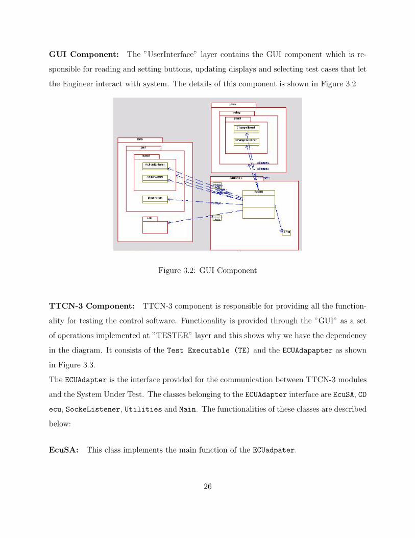
GUI Component: The ”UserInterface” layer contains the GUI component which is re-
sponsible for reading and setting buttons, updating displays and selecting test cases that let
the Engineer interact with system. The details of this component is shown in Figure 3.2
Figure 3.2: GUI Component
TTCN-3 Component: TTCN-3 component is responsible for providing all the function-
ality for testing the control software. Functionality is provided through the ”GUI” as a set
of operations implemented at ”TESTER” layer and this shows why we have the dependency
in the diagram. It consists of the Test Executable (TE) and the ECUAdapapter as shown
in Figure 3.3.
The ECUAdapter is the interface provided for the communication between TTCN-3 modules
and the System Under Test. The classes belonging to the ECUAdapter interface are EcuSA, CD
ecu, SockeListener, Utilities and Main. The functionalities of these classes are described
below:
EcuSA: This class implements the main function of the ECUadpater.
26

Figure 3.3: TTCN-3 Component
CD ecu: This class implements the encoding and decoding functions needed to convert
the TTCN-3 value representations into a bitstring and vice versa. The two functions that
provide these facilities are tciEncode and tciDecode.
SocketListener: Implements a UDP port listener function which runs an infinite loop
listening for exchange of data in the form of UDP packets. The runSocketListener provides
this functionality.
Utilities: This implements the functions required for sending, receiving and synchroniza-
tion of data along with binding function for the socket . It also provided additional functions
required by CDEcu required for conversion.
The remaining classes such as the Tri, Tci, etc. shown in Figure 3.3 are library classes
required by the above mentioned classes.
ECSoftware Component: The ”ECSoftware” layer contains two components- the ECU
and the GlobailIo which is the system that is being tested and it is already fully developed.
The detailed Test Harness Component Architecture showing the components are shown in
27
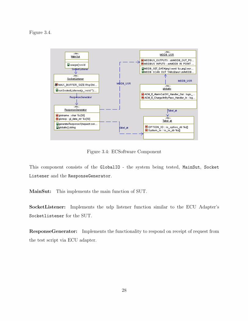
Figure 3.4.
Figure 3.4: ECSoftware Component
This component consists of the GlobalIO - the system being tested, MainSut, Socket
Listener and the ResponseGenerator.
MainSut: This implements the main function of SUT.
SocketListener: Implements the udp listener function similar to the ECU Adapter’s
Socketlistener for the SUT.
ResponseGenerator: Implements the functionality to respond on receipt of request from
the test script via ECU adapter.
28

3.5 Detailed Design
In this section we present the detailed design of a test harness for a control software starting
with a discussion on the details of the analysis model by looking into the technical aspects
of the system and continuing with the design of some of the components in the system.
The classes defined in the architecture section are detailed. In order to deal with the com-
plexities of the system, we divided it into subsystems. To explain this further, a system is
divided up into subsystems whereas a subsystem can be divided up into one or more packages
and a package is divided up into classes. A class on the other hand is divided up into methods.
In the following sections, we present how the test harness for a control software is imple-
mented using both Java, C++ and C. This implementation with the Alpha control software
turned out to be problematic since the compiler we have could not compile it due to some
included library. We tried using a reverse engineered version in Rhapsody but faced similar
problems. We therefore designed our own control software functionality to demonstrate the
workability of the test harness. In the following sections, we present the implementations
starting with the Graphical User Interface.
3.5.1 GUI
The GUI performs all the settings and presentation functions necessary to use the test
harness. The implementation consists of the functionality such as Start, Stop etc. for
Engine simulation and Start Tester, Setscript etc. for test harness. The GUI is shown in
Figure 3.5
The GUI as shown in Figure 3.5 consists of a two-in-one window with very similar layouts.
One window will be used to run the engine simulation independent of the test scripts and
the necessary buttons are implemented. The second window on the other hand will be used
to run and manage the testing of the control software. The Interface will be useful in keeping
29

Figure 3.5: Test Harness User Interface
an organized system that will be based upon ease of use, but still remain fully useful. The
objects within the interface layer would be developed based on the Javax Swing package
using JFrame, JPanel, JLabel, JButton and JTextArea to display text.
Start: This is the starting of the engine simulator to initialize the necessary engine parame-
ters to get it ready to run. This is achieved through a Java Native Interface by instantiating
the native method withing the Java GUI. The following code fragment shows the implemen-
tation of the Start operation.
Listing 3.1: Start Operation code fragment
St r ing s ;
// Too l k i t . g e tDe f au l tToo l k i t ( ) . beep ( ) ;
Global Io1 g io = new Global Io1 ( ) ;
g i o . s= ”Eng . lub . o i l d ens i ty o f mist high ” ;
g i o . b = g io . acces sTab le ( ) ;
in foArea . append ( ”Value o f g i o . s from ECU = ” + gio . s + ”\n” ) ;
logArea . append ( g io . b + ”\n” ) ;
//rpmLevelBar . se tValue (( i n t ) currentRPM + 10) ;
30

Run: The next step in the engine simulation is to run the engine. The parameters are set
and read from the GlobalIO. This is achieved through Java Native Interface as shown in the
code fragment below.
Listing 3.2: Run Operation code fragment
Global Io1 g io = new Global Io1 ( ) ;
g i o . s= ”Eng . lub . o i l d ens i ty o f mist high ” ;
g i o . b = g io . acces sTab le ( ) ;
in foArea . append (
”Value o f g i o . s from ECU = ” + gio . s + ”\n” ) ;
logArea . append ( g io . b + ”\n” ) ;
rpmLevelBar . setValue (
( int ) currentRPM + 10 ) ;
Start Tester: The tester is started before any test case can be run. We achieved this by
creating a Java process that runs a batch file containing the executables of the tester. The
following code fragment shows the how we implemented the ”Start Tester”.
Listing 3.3: Start Tester Operation code fragment
.
Process l s p r o c = Runtime . getRuntime ( ) . exec (
new St r ing [ ] { ” cmd . exe ” , ”/c” ,
”C:\\ Thes i s \\ s t a r t t e s t e r . bat” } ) ;
BufferedReader l s i n = new BufferedReader (
new InputStreamReader ( l s p r o c . getInputStream ( ) ) ) ;
try {
while ( ( l s s t r = l s i n . readLine ( ) ) != nu l l ) {
System . out . p r i n t l n ( l s s t r ) ;
}
} catch ( IOException e t l ) {
System . e x i t ( 0 ) ;
}
} catch ( IOException e t l 1 ) {
System . e r r . p r i n t l n ( e t l 1 ) ;
System . e x i t ( 1 ) ;
}
.
31

Set Script: This functionality is implemented through a Java JFileChooser as shown in
the following code fragment:
Listing 3.4: Set Script Operation code fragment
.
JFi l eChooser chooser = new JFi leChooser ( ) ;
chooser . s e tCur rentDi r ec to ry (new F i l e ( ” . ” ) ) ;
f i n a l Ex t en s i o nF i l eF i l t e r f i l t e r = new Ext en s i o nF i l eF i l t e r ( ) ;
f i l t e r . addExtension ( ” t tcn ” ) ;
f i l t e r . s e tDe s c r i p t i on ( ”TTCN−3 modules” ) ;
chooser . s e t F i l e F i l t e r ( f i l t e r ) ;
int r e s u l t = chooser . showOpenDialog (EcGUI26 . this ) ;
i f ( r e s u l t == JFi leChooser .APPROVE OPTION) {
St r ing t t c n f i l e = chooser . g e t S e l e c t e dF i l e ( ) . getPath ( ) ;
s c r i p tLabe l . setText ( ” [ ” + t t c n f i l e + ” ] ” ) ;
}
try {
Process s l p r o c = Runtime . getRuntime ( ) . exec (
new St r ing [ ] { ”cmd . exe ” , ”/c” ,
”C:\\ Thes i s \\ s e t s c r i p t . bat” } ) ;
BufferedReader s l i n = new BufferedReader (
new InputStreamReader (
s l p r o c . getInputStream ( ) ) ) ;
try {
while ( ( s l s t r = s l i n . readLine ( ) ) != nu l l ) {
System . out . p r i n t l n ( s l s t r ) ;
}
} catch ( IOException e t l ) {
System . e x i t ( 3 ) ;
}
} catch ( IOException e t l 1 ) {
System . e r r . p r i n t l n ( e t l 1 ) ;
System . e x i t ( 4 4 ) ;
}
}
}
Run Test The running of the test scripts is done by the creating a process similar to
starting of the test. Part of the code is presented below.
32

Listing 3.5: Run Test Operation code fragment
.
try {
St r ing l s s t r ;
Process l s p r o c = Runtime . getRuntime ( ) . exec (
new St r ing [ ] { ”cmd . exe ” , ”/c” ,
”C:\\ Thes i s \\ s t a r t t e s t e r . bat” } ) ;
BufferedReader l s i n = new BufferedReader (
new InputStreamReader ( l s p r o c . getInputStream ( ) ) ) ;
try {
while ( ( l s s t r = l s i n . readLine ( ) ) != nu l l ) {
System . out . p r i n t l n ( l s s t r ) ;
}
} catch ( IOException e t l ) {
System . e x i t ( 0 ) ;
}
} catch ( IOException e t l 1 ) {
System . e r r . p r i n t l n ( e t l 1 ) ;
System . e x i t ( 1 ) ;
}
.
3.5.2 ECU
We present only fragments of the ECU to give an idea of what it is because it is proprietary
and not programmed by us. The following presents a fragment of the GlobalIO part of the
ECU.
Listing 3.6: ECU code fragment
.
{
byte TYPE; // I /O Type
word IO ; // I /O nr .
word LINKED IO ; // Linked I /O no .
a l l t y p e s un i o n V; // Data
boolean DAV; // Data changed
boolean FAIL ; // I /O f e j l f l a g .
boolean Disabled ; // I /O Has been d i s a b l e d
boolean Cablebreak ; // I /O Has cab l e b r eak
char TAGNAME[ 6 0 ] ; // I /O navn .
33

} g l d a t a s t r ;
.
.
g l d a t a s t r GLOBAL IO [ ] = {
// Type | I /O | Linked |Da | DAV |FAIL | Disa | Cable | TAGNAME[60 ]
// | | | ta | | | b l ed | break |
{ IO TYPE DIG , 0x8001 , 0x010E , 0 , FALSE, TRUE, TRUE , TRUE,
”ZS4712B@Eng . l o c a l stop switch ( alarm cut o f f ) ” } ,
{ IO TYPE DIG , 0x8001 , 0x1012 , 0 , FALSE, TRUE, TRUE , TRUE,
”ZS4712B@Eng . l o c a l stop switch ( alarm cut o f f ) ” } ,
{ IO TYPE DIG , 0x8001 , 0x5005 , 0 , FALSE, TRUE, TRUE , TRUE, ” } ,
{ IO TYPE DIG , 0x8003 , 0x0229 , 0 , FALSE, TRUE, TRUE , TRUE,
”ACM E DI3@Not Used” } ,
{ IO TYPE DIG , 0x8004 , 0x0103 , 0 , FALSE, TRUE, TRUE , TRUE,
”ZSO1333@Eng . charge a i r by pass va lve open” } ,
{ IO TYPE DIG , 0x8004 , 0x100D , 0 , FALSE, TRUE, TRUE , TRUE,
”ZSO1333@Eng . charge a i r by pass va lve open” } ,
{ IO TYPE DIG , 0x8004 , 0x4026 , 0 , FALSE, TRUE, TRUE , TRUE,
”ZSO1333@Eng . charge a i r by pass va lve open” } ,
{ IO TYPE DIG , 0x8004 , 0x502C , 0 , FALSE, TRUE, TRUE , TRUE,
”LSH1332@Eng . chg a i r mfold water l v l high (OFF=ALARM)” } ,
{ IO TYPE DIG , 0x8007 , 0xFFFF, 0 , FALSE, TRUE, TRUE , TRUE,
”LSH1332@Eng . chg a i r mfold water l v l high (OFF=ALARM)” } ,
{ IO TYPE DIG , 0x8008 , 0x0121 , 0 , FALSE, TRUE, TRUE , TRUE,
”LSL1231@Eng . lub . o i l l e v e l low (OFF=ALARM)” } ,
{ IO TYPE DIG , 0x8008 , 0xFFFF, 0 , FALSE, TRUE, TRUE , TRUE,
”LSL1231@Eng . lub . o i l l e v e l low (OFF=ALARM)” } ,
{ IO TYPE DIG , 0x8009 , 0x1010 , 0 , FALSE, TRUE, TRUE , TRUE, ”
.
We have presented the architecture, the components and implementation of the test harness
system. In the next Chapter, we discuss in detail the TTCN-3 test system.
34

Chapter 4
Testing
In this chapter we give an overview of TTCN-3 system as used in the thesis together with
its architecture and entities.
4.1 TTCN-3 Test System
The general structure of a TTCN-3 Test System is depicted in Figure 4.1. A TTCN-3 Test
System is made up of a set of interacting entities which manage the test execution (interpret
or execute the TTCN-3 code), realize the communication with the SUT, implement external
functions and handle timer operations [12].
Figure 4.1: TTCN-3 Architecture
The test system contains the TTCN-3 Executable (TE), which communicates with the Test-
Management System (TM), the Component Handling (CH) and the Codec (CD) via the
TTCN-3 Control Interfaces. The communication with the System Under Tests is realized
35

by using the TTCN-3 Runtime Interfaces (TRI) which define the interfaces between the TE,
the System Adapter (SA) and the Platform Adapter (PA) [12].
The main components of the test system are as follows:
1. TTCN-3 Executable (TE) interprets or executes the compiled TTCN-3 code. This
component manages different entities: control, behaviour, component, type, value and
queues, entities which are the basic constructors for the executable code.
2. Component Handler (CH) handles the communication between components. The CH
API contains operations to create, start, stop test components, to establish the connec-
tion between test components (map, connect), to handle the communication operations
(send, receive, call and reply) and to manage the verdicts . The information about the
created components and their physical locations is stored in a repository within the
Execution Environment.
3. Test Management (TM) manages the test execution. It implements operations to
execute tests, to provide and set module parameters and external constants. The test
logging is also realized by this component.
4. Coding/Decoding (CD) encodes and decodes types and values. The TTCN-3 values
are encoded into bitstrings which are sent to the SUT. The received data is decoded
back into the TTCN-3 values.
5. System Adapter realizes the communication with the SUT. The communication oper-
ations send, receive, call, getcall, reply, used to interact with the SUT, are defined and
implemented by the System Adapter.Platform Adapter implements the timers and the
external functions. Timers are platform specific elements and have to be implemented
outside the test system.
6. Platform Adapter implements the timers and the external functions. Timers are plat-
form specific elements and have to be implemented outside the test system. The
36
Platform Adapter provides operations in order to handle timers: create, start, stop.
External functions (whose signature is specified in the TTCN-3 specification) are im-
plemented also in the Platform Adapter [12].
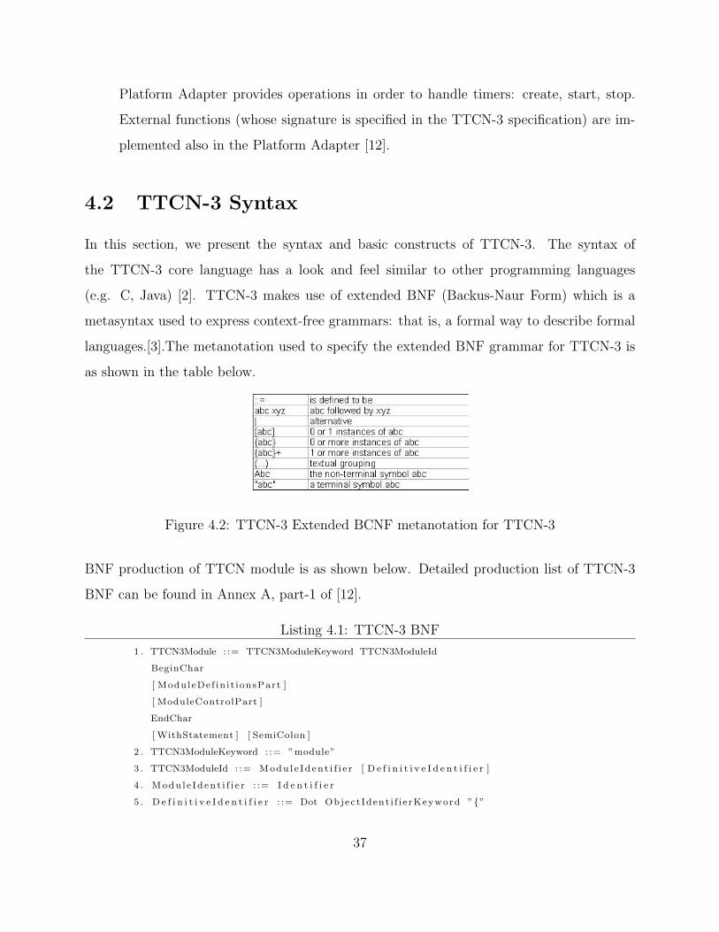
4.2 TTCN-3 Syntax
In this section, we present the syntax and basic constructs of TTCN-3. The syntax of
the TTCN-3 core language has a look and feel similar to other programming languages
(e.g. C, Java) [2]. TTCN-3 makes use of extended BNF (Backus-Naur Form) which is a
metasyntax used to express context-free grammars: that is, a formal way to describe formal
languages.[3].The metanotation used to specify the extended BNF grammar for TTCN-3 is
as shown in the table below.
Figure 4.2: TTCN-3 Extended BCNF metanotation for TTCN-3
BNF production of TTCN module is as shown below. Detailed production list of TTCN-3
BNF can be found in Annex A, part-1 of [12].
Listing 4.1: TTCN-3 BNF
1 . TTCN3Module : := TTCN3ModuleKeyword TTCN3ModuleId
BeginChar
[ ModuleDef in i t ionsPart ]
[ ModuleControlPart ]
EndChar
[ WithStatement ] [ SemiColon ]
2 . TTCN3ModuleKeyword : := ”module”
3 . TTCN3ModuleId : := Modu l e Id en t i f i e r [ D e f i n i t i v e I d e n t i f i e r ]
4 . Modu l e Id en t i f i e r : := I d e n t i f i e r
5 . D e f i n i t i v e I d e n t i f i e r : := Dot Object Ident i f i e rKeyword ”{”
37

Def in it iveObjIdCompnentList ”}”
6 . Def in it iveObjIdComponentList : := {Definit iveObjIdComponent } +
7 . Definit iveObjIdComponent : := Nameform | DefinitiveNumberForm
| DefinitiveNameAndNumberForm
8 . DefinitiveNumberForm : := Number
9 . DefinitiveNameAndNumberForm : := I d e n t i f i e r ” ( ”
DefinitiveNumberForm ” ) ”
4.2.1 Basic language elements
In this section we explain the different language elements that make up TTCN-3 core lan-
guage.
Building block - The Module:
The top-level building-block of TTCN-3 is the module. A module contains all other TTCN-
3 constructs, but cannot contain sub-modules but can import completely or partially the
definitions of other modules. The modules are defined with the keyword module [12]. The
overview of a TTCN-3 module is shown in Figure 4.3 [21].
Figure 4.3: The Overview of TTCN-3 Module
A module has two parts:
38
• The module definition part :The definition part contains the data defined by that mod-
ule (functions, test cases, components, data types, test data templates etc), which can
be used everywhere in the module and can be imported from other modules[12].
Listing 4.2: TTCN-3 Module
module csTest1
{
// De f i n i t i on s par t
type record Message1 { . . . . }
: : : :
f unc t i on preambleSetup1 ( ) { . . . }
// Control par t
c on t r o l { . . . . }
}
• The module control part : The control part is the main program of the module, which
describes the execution sequence of the test cases or functions. It can access the verdicts
delivered by test cases and, according to them, can decide the next steps of execution
[12].
Module Parameters: The module parameter list defines a set of values that are supplied
by the test environment at runtime. The module parameters are declared by listing their
identifiers and types between a pair of curly brackets following the modulepar keyword [12].A
parameter can be initialized with a default value.
Listing 4.3: TTCN-3 Module Parameter
modulepar
{//module parameters with d e f a u l t va lue s
// IP address and port number o f the SUT.
cha r s t r i n g PX SUT IP ADDR1 := ” 1 2 7 . 0 . 0 . 1 ” ;
i n t e g e r PX SUT PORT1 := 6543 ;
}
39

Types and values:
TTCN-3 supports a number of predefined basic types. These basic types include ones nor-
mally associated with a programming language, such as integer, boolean and string types,
as well as some TTCN-3 specific types such as objid and verdicttype.
TTCN-3 supports the following basic string types:
bitstring - a type whose distinguished values are the ordered sequences of zero, one or
more bits. Example: ’00110’B.
hexstring - a type whose distinguished values are the ordered sequences of zero, one, or
more hexadecimel digits. Example: ’3427F’H
octetstring - a type whose distinguished values are the ordered sequences of zero or a
positive even number of hexadecimel digits. Example:’FF96’O.
charstring - a type whose distinguished values are zero, one, or more characters. Ex-
ample:"abcd".
universal charstring - a type can also be denoted by an arbitrary number of char-
acters from the relevant character set, preceded and followed by double quote(”) or by a
”quadruple”. The ”quadraple” is only capable to denote a single character and denotes the
character by the decimal values of its group, plane, row and cell, preceded by the keyword
char included into a pair of brackets and separated by commas. Example: ”this works” and
char (0,0,4,48).
The type keyword is used to specify structured types and user-defined types. Structured
types such as record types, set types and enumerated types can be constructed from these
basic types. With user-defined types it is possible to create sub-types such as lists, ranges
40
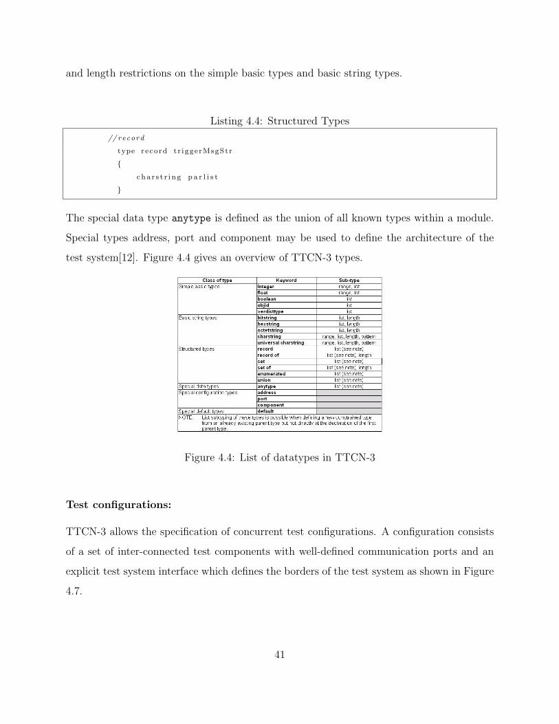
and length restrictions on the simple basic types and basic string types.
Listing 4.4: Structured Types
// record
type record t r igge rMsgStr
{
cha r s t r i n g p a r l i s t
}
The special data type anytype is defined as the union of all known types within a module.
Special types address, port and component may be used to define the architecture of the
test system[12]. Figure 4.4 gives an overview of TTCN-3 types.
Figure 4.4: List of datatypes in TTCN-3
Test configurations:
TTCN-3 allows the specification of concurrent test configurations. A configuration consists
of a set of inter-connected test components with well-defined communication ports and an
explicit test system interface which defines the borders of the test system as shown in Figure
4.7.
41

Figure 4.5: Conceptual view of a TTCN-3 test configuration
Every configuration consists of one main test component (MTC). Test components that are
not MTCs are called parallel test components or PTCs. The MTC is created by the system
automatically at the start of each execution. The behaviour defined in the body of the test
case shall execute on this component. During execution of a test case other components can
be created dynamically by the explicit use of the create operation. Test case ends when the
MTC terminates. When the MTC terminates, all other non-terminated PTCs are stopped
by the test system[12].
Listing 4.5: Test Case
t e s t c a s e Main at ( ) runs on ThComponent system Gio In t e r f a c e
{
preambleSetup1 ( ) ;
thp . send ( Greet ingRequest1 ( ”From , Testharness ! ” ) )
to sut addr ;
thp . r e c e i v e ( GreetingResponse1 ( ”From , Globa l io ! ” ) )
from sut addr ;
s e t v e r d i c t ( pass ) ;
postambleRelease1 ( ) ;
}
In the above example, we can see that the testcase ”Main at“ runs on ThComponent system
GioInterface i.e., it references the type of the Main test component and the test system
interface which is GioInterface on which it executes.
42
Communication between test components and the test system interface is achieved via com-
munication ports. Test component types and port types, denoted by the keywords component
and port, should be defined in the definition part.[12].
Listing 4.6: Test Component
type component ThComponent
{
port ThPort thp ;
const f loat T GUARD DEFAULT1 := 5 . 0 ;
t imer T GUARD1 := T GUARD DEFAULT1;
var address sut addr :=
{
host1 := PX SUT IP ADDR1 ,
por tF i e ld1 := PX SUT PORT1
} ;
var default compDefaultRef1 ;
}
Messages and signatures are used for communication over the communication ports by means
of message exchange and procedure calls . Hence, the ports are message-based, procedure-
based or mixed (i.e. message- and procedurebased) and they are directional. Each port
may have an in, out or inout list; for in, out and both directions, respectively. The test
component in TTCN-3 is an instance of corresponding component type definition. The type
definition declares constants, variables, timers and ports owned by an instance of that type
[12].
Listing 4.7: Port Definition
type port ThPort mixed
{
inout a l lmsg ;
}
43

Test behaviour
The test behaviors in TTCN-3 are defined within functions, altsteps and testcases. Altsteps
are function-like descriptions that are used for structuring component behavior. Altstep has
special semantics used to define an ordered set of alternatives [12].
Listing 4.8: altstep Definition
a l t s t e p De fau l tA l t s t ep1 ( ) runs on ThComponent
{
[ ] thp . r e c e i v e
{
s e t v e r d i c t ( pass ) ; // p r e v i ou s l y f a i l ) ;
stop ;
}
[ ] thp . g e t c a l l
{
s e t v e r d i c t ( f a i l ) ;
s top ;
}
[ ] thp . g e t r ep l y
{
s e t v e r d i c t ( f a i l ) ;
s top ;
}
[ ] thp . catch
{
s e t v e r d i c t ( f a i l ) ;
s top ;
}
[ ] T GUARD1. timeout
{
s e t v e r d i c t ( inconc ) ;
stop ;
}
}
In the above example, in each altstep, setverdict() function is present. The function of
setverdict is to set the outcome i.e., the verdict of the testcase being executed. Verdicts are
used to record test results wherein one final verdict is recorded per test case which is set by
test system only. The verdicts can be:
44

• pass non-conformance has not been found
• fail indication of non-conformance has been found
• inconc inconclusive, pass/fail classification is not possible
• none no verdict has been assigned
• error error in test execution: test suite, tool, adapter, etc.
4.2.2 Test System Interfaces
A TTCN-3 test system has two interfaces, the TTCN-3 Control Interface (TCI) and the
TTCN-3 Runtime Interface (TRI) as shown in Figure ??.
Figure 4.6: General Structure of a TTCN-3 Test System [12]
A brief description of these interfaces are given in the following subsections.
TTCN-3 Control Interface(TCI)
The TCI defines the interaction between the TTCN-3 Executable (TE), Component Handling
(CH), the Test Management (TM), the Coding/Decoding (CD), the Test Logging (TL)
entities within a TTCN-3 test system. It provides means for the TE to:
45
• manage test execution;
• distribute execution of test components among different test devices;
• encode and decode test data; and
• logging of information about test execution.
The TCI consists of four sub-interfaces:
• TCI Test Management Interface (TCI-TM): This interface includes all operations
needed to manage test execution, provide module parameters and external constants
and provide test event logging.
Listing 4.9: TCI
void t c iS ta r tTes tCase ( ) ;
void tc iStopTestCase ( ) ;
void t c i S t a r tCon t r o l ( ) ;
void t c iS topCont ro l ( ) ;
• TCI Component Handling Interface (TCI-CH): The basic principle is that TCI-CH is
not implementing any kind of TTCN-3 functionality. Instead it will be informed by the
TE that for example a test component shall be created. Based on Component Handling
(CH) internal knowledge the request for creation of a test component will be transmit-
ted to another (remote) participating TE. This second (remote) participating TE will
create the TTCN-3 component and will provide a handle back to the requesting (local)
TE. The requesting (local) TE can now operate on the created test component via
this component handle[12]. It includes operations to create, start and stop test com-
ponents, establish connection between TTCN-3 components, manage test components
and their verdicts, and handle message and procedure based communication between
TTCN-3 components.
Listing 4.10: TCI-CH
void tciStartTestComponent ( in TriComponentIdType component ,
46

in TciBehaviourIdType behaviour ,
in TciParamaterListType parameterLi s t )
void tciStopTestComponent ( in TriComponentIdType component )
• TCI Coding/Decoding Interface (TCI-CD): This interface includes all operations needed
to retrieve and access codecs, i.e. encoders or decoders, for encoding data to be sent,
defined using the TTCN-3 encode attribute, and to decode received data.
Listing 4.11: TCI-CD
BinaryStr ing tc iEncode ( TciValue value )
TciValue tc iDecode ( BinaryStr ing message ,
TciType decHypothes is )
• TLI Test Logging Interface (TCI-TL): This interface includes all operations needed
to retrieve information about test execution and to control the level of detail of these
information.
Listing 4.12: TCI-TL
void t c iTes tCaseStar t ed ( ) ;
void tc iTestCaseTerminated ( ) ;
void tc iContro lTerminated ( ) ;
void tc iLog ( S t r ing message ) ;
void t c iE r r o r ( S t r ing message ) ;
TTCN-3 Runtime Interface:
In Figure4.7, we have explained the abstract test system which is GioInterface. The actual
implementation of the abstract test system interface in a particular test system is the real
test system interface which is ECUadpater in our implementation. It is implemented as the
SUT adapter and Platform adapter(Which is not implemented for the current SUT).
For implementing the real test system interface, TTCN-3 provides the TTCN-3 Runtime
Interface (TRI) which is specified in [12]. TRI has two sub-interfaces: communication (tri-
47

Figure 4.7: Conceptual view of a TTCN-3 test configuration
Communication) and platform (triPlatform) which correspond to the communication with
SA and PA respectively. The principle operation of TRI is the send operation which is used
to send messages between TTCN-3 executable with the TTCN-3 adapters.
Listing 4.13: Send Operation
thp . send ( Greet ingRequest1 ( ”From , Testharness ! ” ) ) to sut addr
The above function sends the message from test executable to the SA. The corresponding
function in the TRI is:
Listing 4.14: TRI function
t r iSend ( const TriComponentId∗ componentId ,
const TriPortId ∗ t s iPor t Id ,
const TriAddress ∗ sutAddress ,
const TriMessage∗ sendMessage )
The communication between the TTCN-3 ETS and the SUT includes many other oper-
ations which can be found in [12] part 5.
In order to compile and execute test cases, we have used the OpenTTCN tool which provides
the following features[5]:
48

1. OpenTTCN has a powerful and standard-based scripting mechanism for rapid realiza-
tion of test purposes. The scripting support enables advanced test scripts written in
standardized TTCN-3 Core Notation testing language.
2. OpenTTCN provides comprehensive and automatic visualization of the test execution
and message traffic, including detailed message contents, between the SUT and tester
with which the SUT communicates.
3. OpenTTCN has a intuitive test management and control user interface. This provides
an easy to use test operations. End-user or test system vendor specific users interfaces
can be integrated using standardized interfaces based on the TTCN-3 Control Interface
specification.
4. OpenTTCN is independent of the environment in which the SUT runs. The access
to SUT is realized by implementing an adapter using standardized interfaces based on
the TTCN-3 Run-Time Interface specification.
49

Chapter 5
Experiments
This Chapter presents the use of the system by providing a guide to installing all the nec-
essary programs needed to run the system. It continues with an illustration of writing test
scripts, running test scripts and finally presents the use of the Engine Simulator.
5.1 Using The System
The system is composed of two parts- the Test Harness and the Engine Simulator. The Test
Harness is used to test the functionality of the control software by checking through the values
of the engine as the control software runs. In order to do this, a test script is written and
connected to the system under test (SUT) in this case the GlobalIO during runtime to check
whether the current values conforms with the expected values. The following subsections
give the details on the use of the system.
5.1.1 Installation
As mentioned in the preceding chapters, we have used C, C++, Java and OpenTTCN in
the thesis and to run the example, we one have to make some installations. It is assumed
that a recent Java Runtime Environment (or SDK) is in the computer in which to example
is to be run. The second installation is the OpenTTCN and it is assumed that below are
the installation instructions.
OpenTTCN Tester for Windows is installed using an installer that automates the first part
of the installation process. After the first part of the installation, the user needs to perform
50

the following installation steps:
1. add a OpenTTCN.lic license file to the Tester3\etc directory
2. check that INSTALL PATH setting in the Tester3\bin\commonenv.bat file is correct
3. check that Java JRE 1.3.1 or 1.4.2 or 1.5 Update 1 is installed in the system and is
accessible
4. if Windows Me, 98, or 95 is used, check that the size of the command shell environment
space is large enough, and adjust settings according to the used operating system.
OpenTTCN Tester Installation Instructions [5]: The default installation directory
for OpenTTCN Tester for Windows is: C:\Program Files\OpenTTCN\Tester3.
1. Adding OpenTTCN.lic license file to Tester3\etc directory Download the ”OpenTTCN.lic”
license file from http://www.openttcn.com/updates and copy it to the Tester3\etc di-
rectory.
2. Checking that INSTALL PATH setting in the Tester3\bin\commonenv.bat file is cor-
rect. You should change INSTALL PATH setting in the ”Tester3\bin\commonenv.bat”
if you have installed OpenTTCN Tester to other location than prompted by the in-
staller.
3. Checking and increasing environment space in Windows Me, 98, and 95. In Windows
95, Windows 98, and Windows Me, the environment space reserved by default (256
bytes) for the batch file and command interpreter may be too small. Add the environ-
ment space available using the following instructions from Microsoft:
• Right-click the MS-DOS Prompt shortcut, and then click Properties.
• Click the Memory tab.
• In the Initial Environment box, set the initial environment size to 4096 (the size is
51

between 256 and 4096 bytes in 256-byte increments).
• Click OK.
4. Checking that Java JRE 1.3.1 or a newer version is installed in the system and ac-
cessible. A recent Java JRE (or JDK) is required for the installation. Currently the
JRE 1.4.2 is supported, but the used libraries are known to work with JRE versions
1.3.1 and newer. If required, download necessary JRE from http://java.sun.com/j2se
and install it by following the installation instructions from Sun. After installation,
or if compatible JRE is already installed, please make sure that ”java.exe“ is in your
path. Java is used by the ”importer3“ command of the OpenTTCN software package.
OpenTTCN is now installed.
Installing the GUI of the system: Copy the ”Thesis“ Folder from the CD to the root
directory of the computer in which the system is to run.
Having covered the setting up of the system, the next is a description on how the scripts are
written.
5.1.2 Writing Test Scripts
This subsection presents what is involved in writing a test script. In order to do this one
should have either a text editor or any editor supporting TTCN-3.
Write modules
The first step is to write and debug test modules following the TTCN-3 syntax for instance.
The test script is written on the basis of the software specifications. Thus, the different
parts of the test script should cover the component definition, the communication definitions
(ports), the behavior and the test data definitions among other entities. These modules form
the abstract test suite.
52

Write a testing interface
The second step is to create a testing interface between the abstract test suite and the system
under test (SUT). The purpose of the interface is to provide the connection between the
behavior in the modules, the software unit and the test execution engine. The ecuAdapter
interface discussed in Chapter 4 was used in the test harness system. The following subsection
takes care of the execution of test scripts.
5.1.3 Running Test Scripts
The Test Harness window includes all the necessary commands to run the test scripts. The
window allows the user to select test cases, set where the logs will be saved and run selected
test script among other commands. The Test Harness window is shown in Figure 5.1.
Figure 5.1: Test Harness Window
53

Described below are the steps that will be followed to run a test.
1. Start the Testing Server: This is done by clicking on the ”Start Tester“ button.
2. Select a test case to run: Achieved by clicking on ”Select Script“ which opens a File-
Chooser dialog for one to choose a test case. For this example choose ”csTest22.ttcn“
3. Run a test case: Clicking the ”Run Test“ test button, loads the module that contains
the test case to be run and executes the test case.
4. Review test results: At the end execution, the result is reviewd.
5. Stop the Testing Server. Clicking the ”Stop Tester“ stops the server.
5.1.4 Using The Engine Simulator
Changes in the engine state are simulated automatically ”in the background” by the com-
puter. The Engine Simulator window provides the engineer with the commands to start the
virtual engine, run a particular functionality, stop the engine and view the effect of running
the functionality (i.e. view of engine status at different points) as shown in Figure 5.2.
Start: This button starts the Engine Simulator by initializing all the necessary parameters
to run the engine. For instance the following parameters are read and observed from the
Globalio.
Run: The run button starts the Engine Simulator by initializing all the necessary values
to run the engine. For instance, the following values and read from the Globalio and used
to initialize the operation.
Stop: The ”Stop” button stops the simulation. Below the buttons is the information area
where the different values and status of the engine are display as the engine runs.
54

Figure 5.2: Engine Simulator Window
The Engine Simulator is very useful since it provides a view of the engine status while the
test case is run on the adjacent window. Thus, one can easily see the two views of the
parameters observed at the same time.
55

5.2 Example
In this section, we present the example runs of the test harness of the control software for
the marine diesel engine as at the time of this report. The figures showing the Main at test
case execution is presented below.
Figure 5.3 shows the sample run of the control software.
Figure 5.3: Example System Under Test
Figure 5.4 shows the sample run of ecu adapter.
The result is shown in the next page.
56

Figure 5.4: Example System Under Test Adapter
Listing 5.1: Test Result
∗∗∗∗∗∗∗∗∗∗∗∗∗∗∗∗∗∗∗∗∗∗∗∗∗∗∗∗∗∗∗∗∗∗∗∗∗∗∗∗∗∗∗∗∗∗∗∗∗∗∗∗∗∗∗∗∗∗∗∗∗∗∗∗∗∗∗∗∗∗∗∗∗∗∗∗∗
∗∗∗ RUNNING TEST CASE Main at
Tester : {22 . 30 . 19 . 809} : // Time : 22 .30 .19 .809 . Date : 09/Jun/2005. MOT vers ion : TC: 2 . 5 3 . 0 .RC1.
mtc : {22 . 30 . 19 . 829} : // CASE Main at STARTED
mtc : {22 . 30 . 19 . 829} : l og (
”−−− sending parameters ” ) ;
mtc : {22 . 30 . 19 . 829} : map(mtc : thp , system : t s iPo r t ) ;
mtc : {22 . 30 . 19 . 829} : T GUARD1. s t a r t ( 5 . 0 ) ; // Timer i s s t a r t e d : durat ion 5 s .
mtc : {22 . 30 . 19 . 839} : l og (
”−−− sending parameters ” ) ;
mtc : {22 . 30 . 19 . 839} : thp . send ( Message1 Greet ingRequest1 :=
{
typeCode1 := ’ 01 ’O,
tpayload :=
{
l en := 18 ,
giorpmhout := ”From , Testharness ! ”
}
}
57

Listing 5.2: Test Result Continued..
/∗−−−−−−−−−−−−−−−−−−−−−−−−−−−−−−−−−−−−−−−−−−−−−−−−−−−−−−−−−−−−−−−−−−−−−−−−
ENCODED VALUE IN HEXADECIMAL FORMAT: 21 OCTETS
>>>>>
01 00 12 46 72 6F 6D 2C 20 54 65 73 74 68 61 72 6E 65 73 73 21
>>>>>
−−−−−−−−−−−−−−−−−−−−−−−−−−−−−−−−−−−−−−−−−−−−−−−−−−−−−−−−−−−−−−−−−−−−−−−−∗/
) to
{
host1 := ” 1 2 7 . 0 . 0 . 1 ” ,
po r tF i e ld1 := 6543
}
;
mtc : {22 . 30 . 19 . 889} : thp . r e c e i v e ( Message1 $any :=
{
typeCode1 := ’ 02 ’O,
tpayload :=
{
l en := 49 ,
giorpmhout := ”ZS4712B@Eng . l o c a l stop switch ( alarm cut o f f )8001 ”
}
}
Listing 5.3: Test Result Continued..
/∗−−−−−−−−−−−−−−−−−−−−−−−−−−−−−−−−−−−−−−−−−−−−−−−−−−−−−−−−−−−−−−−−−−−−−−−−
ENCODED VALUE IN HEXADECIMAL FORMAT: 54 OCTETS
>>>>>
02 00 31 5A 53 34 37 31 32 42 40 45 6E 67 2E 20 6C 6F 63 61 6C 20 73 74 6F
70 20 73 77 69 74 63 68 20 28 61 6C 61 72 6D 20 63 75 74 20 6F 66 66 29 38
30 30 31 01
>>>>>
−−−−−−−−−−−−−−−−−−−−−−−−−−−−−−−−−−−−−−−−−−−−−−−−−−−−−−−−−−−−−−−−−−−−−−−−∗/
) from
{
host1 := ” 1 2 7 . 0 . 0 . 1 ” ,
po r tF i e ld1 := 6543
}
;
mtc : {22 . 30 . 19 . 889} : s e t v e r d i c t ( pass ) ;
mtc : {22 . 30 . 19 . 889} : // CASE Main at FINISHED
mtc : {22 . 30 . 19 . 889} : // VERDICT Main at PASS
58

∗∗∗∗∗∗∗∗∗∗∗∗∗∗∗∗∗∗∗∗∗∗∗∗∗∗∗∗∗∗∗∗∗∗∗∗∗∗∗∗∗∗∗∗∗∗∗∗∗∗∗∗∗∗∗∗∗∗∗∗∗∗∗∗∗∗∗∗∗∗∗∗∗∗∗∗∗
∗∗∗ TEST EXECUTION SUMMARY
Pass Fa i l Inconc None Error Total Duration
1 0 0 0 0 1 00 : 00 : 01
59

Chapter 6
Conclusion
We have presented a test harness for a control software developed using a model-based de-
velopment approach. Model-based development approach was successfully employed in the
development of the test harness.
In this Chapter, we discuss our experience with model based development in the devel-
opment of a test harness of a control software for a marine diesel engine and creation of test
scripts using TTCN-3 followed by further work and summary.
6.1 Use of Model Based Development
In Chapter 2, we presented the analysis of the test harness and Chapter 3 described design
architectures and detailed design dealing with the use of model based development to develop
the test harness. The following discussion is based on these two Chapters.
6.1.1 Analysis
As an application example, a test harness for a control software of a marine diesel engine
was developed. We started by acquiring the requirements for the system by applying Ob-
jected Oriented and Analysis and Design through which we came up with the architecture
to illustrate our view of the system. We identified the users and the different operations that
should be handled by the system. This was done through the development of the use case
diagrams. We also develop the static structure of the different components (objects/classes)
that collaborate in the overall test harness system. This was illustrated through different
60

component diagrams.
An observation in using model based approach is the importance of understanding the mean-
ing and implications of user stories at the beginning of the application domain where the
designers have little prior knowledge. In our case, we had only a very abstract understanding
of the ECU of a marine diesel engine. The information given by the user i.e., user stories
play an important role in gaining the required information regarding the software to be de-
veloped. To extract the right meaning of the user stories, the tools used such as use cases
and rich picture played a central role.
Models are easy to understand and maintain. This became obvious when we presented the
design to an experienced engineer from Alphashipmate. He was able to understand and
follow the design because of the model-based approach. Any model parameter is easy to
change and rerun. This helps to easily make changes in our models as new ideas come in.
We did not find it difficult to make changes after being pointed by the Engineer in the first
stage of the project. Models serve as executable specifications, replacing ambiguous text
documents. This is very evident in our case as we have to write lesser lines of code through
the model.
6.1.2 Design
Model Based Development evolves system architecture to the module level. As demonstrated
in the thesis, the system architecture was followed to extract the different modules for the
system. This was done by looking at the different components that interact within the sys-
tem. These components formed the bases for the modules
Models are easy to share with designers, and reduce their need to build physical prototypes.
Instead, designers can simulate and iterate as many times as necessary to refine the model to
meet the constraints of the target environment, and to validate the system behavior against
61

the requirements.
Model-Based approach provided us with the advantages mentioned above in our development
process and above all serves as excellent documentation of the implemented system.
6.1.3 Summary
Though model based development worked for us in the development and testing of the con-
trol software, there has been no formal methodology provided to maintain the changes that
take place to the analysis document during the different iterations. Since analysis document
consists of rich picture, FACTOR criteria, use case diagrams, etc, any changes have to be
updated. Updating and maintaining of these changes during different iterations makes the
analysis document increase considerably making the maintenance cumbersome and leads to
confusion.
We encountered drawbacks at different phases of the development of the test harness. During
the application domain analysis phase, we observed that the extraction of appropriate (right)
meaning and implications of the user stories play a crucial role in deriving the objective of
the software being developed. Deducing the right meaning of user stories became even more
terse when dealing with projects related to different field of study. The knowledge of the
user in that particular field of study has to be tapped in the user stories required to derive
the objective of the software. For example, in our case, the knowledge about the working of
the control software and marine diesel engine had to be deduced from the user stories. The
user in our case was an experienced engineer from Alpha shipmate.
On the basis of user stories, a rich picture and the use case diagrams were produced to
analyze and deduce the objective of the system. The deductions from the initial user stories
were not appropriate enough to derive the objective of the system to be developed. Hence,
a prototype of the software was developed but did not cover the full user requirements. On
62

demonstration of the prototype and with the mediation of our supervisor we got the objective
of the system right i.e., to develop a test harness for the control software of the marine diesel
engine.
6.2 Development of A Test Harness
The selection of TTCN-3 was a good idea because it gave us a frame work to write test
scripts. The framework has for instance the module entity where the different components,
ports, test data, etc are defined. This modular aspect is similar to the object oriented
approach and hence retaining the object orientation provided by Java or C++. This saved
us the time to develop a new way of writing test scripts. It also separates the tests from the
system to be tested thus increasing productivity through division of labor.
6.2.1 TTCN-3
Chapter 4 discussed TTCN-3 and its use in the thesis. Initially our objective was to adapt
the tool to a conventional software design outside the telecommunication industry but we
discovered during the process that the tool has been extended to include other areas of soft-
ware testing though not so much have been implemented to the best of our knowledge. This
thesis has therefore demonstrated the use of TTCN-3 to test an embedded software with
heterogeneous components.
TTCN-3 has well defined syntax,static, and operational semantics and a powerful core no-
tation.
Moreso, it is based on series of standards which means that it cannot die soon. Notable
standards can be found in [12].
The test harness has a communication nature and the components that fits into TTCN
63

semantics and the company has a form of network connection which can be done through
TCP/IP (foundation of TTCN).
TTCN-3 was very useful to us as it provided an environment to write the test scripts. The
module definition and the control part has specific artifacts to fill in therefore one does not
have to worry about where to place port definitions or test data for instance.
6.3 Further Work
Although, we have developed the test harness for the control software together with the
Engine Simulator through model-based approach, extension can be done through further
work as discussed below.
From Prototype to Production Test Harness: We have implemented a prototype of
a test harness. Further extension of this prototype to a full fledged production test harness
can be explored. This could be done by writing test cases for all the functionalities to get
a complete test suite for the control software. a full understanding of the functionalities of
the engine is need in order to write the scripts. The test harness remains unchanged except
for the addition of the new test scripts.
Methodology: An appropriate methodology to handle systems with a mixture of hetero-
geneous components can be explored. In the thesis, we interlinked the different languages
through native codes. For instance, we programmed Java Native Interface to hook up C++
functions. This requires that one should know how to program and hook the different func-
tions from different programming languages. A possible alternative could be automatic code
generation where the knowledge of programming a native code is not a prerequisite. The
different language elements can be modeled and codes can be automatically generated. A
tool that supports mixture of heteregeneous components would have given a tremendous
help.
64

6.4 Summary
This thesis presented the discussion on the use of Objected Oriented Analysis and a Model
Based Design Approach. The models were developed with the UML tool Rhapsody. Exam-
ples on the use of this approach were presented. These include system definition, use cases,
class diagrams, component diagrams, etc.
As a concrete outcome, we developed a test harness for the Engine control software. We
used the Alpha Shipmate Engine control software of a marine diesel engine as a case study.
The test harness included a Java GUI, Testing and Test Control Notation Version 3 test
scripts and engine control functions interfaced with Java Native Interfaces. The system is
operational with a support for selection and execution of test cases. We have scheduled a
meeting with an experienced engineer from Alphashipmate to give a demonstration of the
system for acceptance.
The Engine Simulator is a secondary objective but we implemented it in order to give a view
of the interaction between the control software and the engine. It is independent of the test
harness and has buttons to start and run the engine together with an area to log the engine
parameters affected during the run operation.
65

References
[1] Ansi ieee 829-1983 ieee standard for software test documentation - description, 1998.
http://standards.ieee.org/reading/ieee/std/se/829-1998.pdf.
[2] Agile modeling and extreme programming (xp), 2005. http://www.agilemodeling.com/
essays/ agileModelingXP.htm/ ModelingAndXP.
[3] Backus-naur form, 2005. http://en.wikipedia.org/wiki/Backus-Naur-form.
[4] Modbus protocol, 2005. http://www.modbus-ida.org.
[5] Openttcn tester for ttcn-3, 2005. http://www.openttcn.com/Sections/Products/OpenTTCN3.
[6] Joseph (Eds.) Bouyssounouse, Bruno; Sifakis. Embedded Systems Design -The ARTIST
Roadmap for Research and Development. Springer Verlags, GmbH, 2005. Series: Lecture
Notes in Computer Science, Vol. 3436.
[7] A. Eden and Kazman R. Defining architecture, design and implementation. Portland,
OR, 2003.
[8] Ralph Johnson Erich Gamma, Richard Helm and Johnn Vlissides. Design Patterns-
Elements of Reusable Object-Oriented Software. Addison-Wesley Publishing Company,
Massachusetts Menlo Park, California, USA, 1995.
[9] The Open Group. Architecture patterns, 2002. http://www.opengroup.org/ architec-
ture/ togaf8-doc/ arch/ p4/ patterns/ patterns.htm/ ModelingAndXP.
[10] David Houdyschell. A diesel two-stroke linear engine, 2002. Master Thesis.
[11] J. Grabowski A. Rennoch I. Schieferdecker, Z. R. Dai. The uml 2.0 testing profile and
its relation to ttcn-3. 2003. http:www.itm.mu-luebeck.de/publications/ TestCom2003
UTP Final.pdf/ the-uml-testing-profile.pdf.
66
[12] European Telecommunication Standards Institute. Testing and test control notation
version 3. 2005. http://www.etsi.org/ptcc/ttcn3ed3.htm.
[13] ITU. The evolution of ttcn. 2001. http://www.itu.int/ITU-
T/studygroups/com07/ttcn.html.
[14] Grady Booch James Rumbaugh and Ivar Jacobson. The Unified Modeling Language
Reference Manual. Pearson Education, USA, 2004.
[15] Gyorgy Rethy Ina Schieferdecker Anthony Wiles Jens Grabowski, Dieter Hogrefe and
Colin Willcock. An introduction into the testing and test control notation (ttcn-3).
2003.
[16] Ghica van Emde Boas Jorn Bettin, Craig Cleaveland and Markus Voelter. Model-driven
software development. 2005. http://www.mdsd.info/mdsd cm/page.php.
[17] Jessica Keys. Software Engineering Handbook. Auerbach publications, New York, 2003.
[18] Stefan Kluj, 1997. Turbo Diesel 2.0.
[19] P. A. Nielsen L. Mathiassen, A. Munk-Madsen and J. Stage. Object Oriented Analysis
and Design. Marko Publishing ApS, Aalborg, Denmark, 2000, 2000.
[20] Lockergnome. Electronic control unit. Technical report,
http:/encyclopedia.lockergnome.com/s /b /Electronic control unit, May 2005.
[21] Pekka Mki-Asiala. Reuse of ttcn-3 code. In TTCN-3-koodin uudelleenkytt, page 112,
Finland, 2005. VTT Publications.
[22] N.I. Xiros K.Marek N.P. Kyrtatos, G. Theotokatos and R. Duge. Transient operation of
large-bore two-stroke marine diesel engine powerplants: Measurements and simulations.
Technical report, Laboratory of Marine Engineering, National Technical University of
Athens, 1999.
67

[23] J. Schaffnit R. Iserman and S. Sinsel. Hardware-in-the-loop simulation for the design
and testing of engine-control systems. Technical report, Institute of Automatic Control,
Laboratory of Control Engineering and Process Automation, Technical University of
Darmstadt, Germany, 1998.
[24] I-Logix Inc. Rhapsody, 2005. Three Riverside Drive, Andover, MA 01810.
[25] Michael G Schwern. Test harness, 2005. http://search.cpan.org/dist/Test-
Harness/lib/Test/Harness.pm.
[26] Daniel H. Steinberg and Daniel W. Palmer. Extreme Software Engineering. Pearson
Education (Upper Saddle River), New Jersey, USA, 2004.
[27] International Telecommunication Union, 2005. http://www.itu.int/ITU-T/.
[28] Pingjian LIU Yihuai HU, Xihuai WANG and Xianfu HU. Fault simulation of main
engine system for engine room simulator. Technical report, Shanghai Maritime Univer-
sity,Pudong Dadao, Pudong New Area, Shanghai 200135, P. R. China, 2001.
68

Appendix A
Overview of the CD-ROM
The attached CD-ROM contains the following:
Report : The report in .pdf format. In folder - report.
Report latex source: The latex source in folder- report.
Test Harness source: The source code procided in here consists of the Java source files
for GUI, TTCN-3 files for the test case and the C source file for the JNI function. But the
source code provided by Alpha Shipmate for the control software has not be provided. In
folder - testsource.
Executables of Test Harness source: Consists of the executable required for the exe-
cution of Test Harness software. For the execution steps, please refer chapter 5. In folder -
testexe.
69

Appendix B
IDL Summary
The summary of the IDL definition of TRI operations for the TRI interface discussed in
chapter 4 is as follows:
Listing B.1: TTCN-3 BNF
// ∗∗∗∗∗∗∗∗∗∗∗∗∗∗∗∗∗∗∗∗∗∗∗∗∗∗∗∗∗∗∗∗∗∗∗∗∗∗∗∗∗∗∗∗∗∗∗∗∗∗∗∗∗∗∗∗∗∗∗∗∗∗∗∗∗∗∗∗∗∗∗∗∗
// In t e r f a c e d e f i n i t i o n fo r the TTCN−3 Runtime In t e r f a c e
// ∗∗∗∗∗∗∗∗∗∗∗∗∗∗∗∗∗∗∗∗∗∗∗∗∗∗∗∗∗∗∗∗∗∗∗∗∗∗∗∗∗∗∗∗∗∗∗∗∗∗∗∗∗∗∗∗∗∗∗∗∗∗∗∗∗∗∗∗∗∗∗∗∗
module t r i I n t e r f a c e
{
//
// ∗∗∗∗∗∗∗∗∗∗∗∗∗∗∗∗∗∗∗∗∗∗∗∗∗∗∗∗∗∗∗∗∗∗∗∗∗∗∗∗∗∗∗∗∗∗∗∗∗∗∗∗∗∗∗∗∗∗∗∗∗∗∗∗∗∗∗∗∗∗∗∗∗
// Types
// ∗∗∗∗∗∗∗∗∗∗∗∗∗∗∗∗∗∗∗∗∗∗∗∗∗∗∗∗∗∗∗∗∗∗∗∗∗∗∗∗∗∗∗∗∗∗∗∗∗∗∗∗∗∗∗∗∗∗∗∗∗∗∗∗∗∗∗∗∗∗∗∗∗
//
// Connection
nat ive TriPortIdType ;
typedef sequence<TriPortIdType> TriPortIdListType ;
nat ive TriComponentIdType ;
// Communication
nat ive TriMessageType ;
nat ive TriAddressType ;
nat ive TriSignatureIdType ;
nat ive TriParameterType ;
typedef sequence<TriParameterType> TriParameterListType ;
nat ive TriExceptionType ;
// Timing
nat ive TriTimerIdType ;
70

nat ive TriTimerDurationType ;
// Misce l laneous
nat ive TriFunctionIdType ;
nat ive TriTestCaseIdType ;
nat ive TriActionTemplateType ;
nat ive TriStatusType ;
//
// ∗∗∗∗∗∗∗∗∗∗∗∗∗∗∗∗∗∗∗∗∗∗∗∗∗∗∗∗∗∗∗∗∗∗∗∗∗∗∗∗∗∗∗∗∗∗∗∗∗∗∗∗∗∗∗∗∗∗∗∗∗∗∗∗∗∗∗∗∗∗∗∗∗
// In t e r f a c e s
// ∗∗∗∗∗∗∗∗∗∗∗∗∗∗∗∗∗∗∗∗∗∗∗∗∗∗∗∗∗∗∗∗∗∗∗∗∗∗∗∗∗∗∗∗∗∗∗∗∗∗∗∗∗∗∗∗∗∗∗∗∗∗∗∗∗∗∗∗∗∗∗∗∗
//
//
// ∗∗∗∗∗∗∗∗∗∗∗∗∗∗∗∗∗∗∗∗∗∗∗∗∗∗∗∗∗∗∗∗∗∗∗∗∗∗∗∗∗∗∗∗∗∗∗∗∗∗∗∗∗∗∗∗∗∗∗∗∗∗∗∗∗∗∗∗∗∗∗∗∗
// The communication i n t e r f a c e (Ref : TRI−De f in i t i on : 7 .5)
// ∗∗∗∗∗∗∗∗∗∗∗∗∗∗∗∗∗∗∗∗∗∗∗∗∗∗∗∗∗∗∗∗∗∗∗∗∗∗∗∗∗∗∗∗∗∗∗∗∗∗∗∗∗∗∗∗∗∗∗∗∗∗∗∗∗∗∗∗∗∗∗∗∗
//
i n t e r f a c e triCommunication
{
// Reset operat ion
// Ref : TRI−De f in i t i on 7 . 5 . 1
TriStatusType tr iSAReset ( ) ;
// Connection hand l ing opera t ions
// Ref : TRI−De f in i t i on 7 . 5 . 2
TriStatusType tr iExecuteTestCase ( in TriTestCaseIdType testCaseId ,
in TriPortIdListType t s i P o r t L i s t ) ;
// Ref : TRI−De f in i t i on 7 . 5 . 3
TriStatusType triMap ( in TriPortIdType compPortId , in TriPortIdType t s iPo r t I d ) ;
// Ref : TRI−De f in i t i on 7 . 5 . 4
TriStatusType triUnmap ( in TriPortIdType compPortId , in TriPortIdType t s iPo r t I d ) ;
// Message based communication opera t ions
// Ref : TRI−De f in i t i on 7 . 5 . 5
71

TriStatusType t r iSend ( in TriComponentIdType componentId , in TriPortIdType t s iPor t Id ,
in TriAddressType SUTaddress , in TriMessageType sendMessage ) ;
// Ref : TRI−De f in i t i on 7 .5 . 6
void triEnqueueMsg ( in TriPortIdType t s iPo r t I d , in TriAddressType SUTaddress ,
in TriComponentIdType componentId , in TriMessageType rece ivedMessage ) ;
// Procedure based communication opera t ions
// Ref : TRI−De f in i t i on 7 .5 . 7
TriStatusType t r i C a l l ( in TriComponentIdType componentId , in TriPortIdType t s iPor t Id ,
in TriAddressType SUTaddress , in TriSignatureIdType s ignature Id ,
in TriParameterListType parameterLi s t ) ;
// Ref : TRI−De f in i t i on 7 .5 . 8
TriStatusType t r iRep ly ( in TriComponentIdType componentId , in TriPortIdType t s iPor t Id ,
in TriAddressType SUTaddress , in TriSignatureIdType s ignature Id ,
in TriParameterListType parameterList , in TriParameterType returnValue ) ;
// Ref : TRI−De f in i t i on 7 .5 . 9
TriStatusType t r iRa i s e ( in TriComponentIdType componentId , in TriPortIdType t s iPor t Id ,
in TriAddressType SUTaddress , in TriSignatureIdType s ignature Id ,
in TriExceptionType except ion ) ;
// Ref : TRI−De f in i t i on 7 .5 .10
void t r iEnqueueCal l ( in TriPortIdType t s iPor t Id , in TriAddressType SUTaddress ,
in TriComponentIdType componentId , in TriSignatureIdType s i gnature Id ,
in TriParameterListType parameterLi s t ) ;
// Ref : TRI−De f in i t i on 7 .5 .11
void tr iEnqueueReply ( in TriPortIdType t s iPor t Id , in TriAddressType SUTaddress ,
in TriComponentIdType componentId , in TriSignatureIdType s i gnature Id ,
in TriParameterListType parameterList , in TriParameterType returnValue ) ;
// Ref : TRI−De f in i t i on 7 .5 .12
void tr iEnqueueExcept ion ( in TriPortIdType t s iPor t Id , in TriAddressType SUTaddress ,
in TriComponentIdType componentId , in TriSignatureIdType s i gnature Id ,
in TriExceptionType except ion ) ;
// Misce l laneous opera t ions
72

// Ref : TRI−De f in i t i on 7 .5 .13
TriStatusType tr iSUTact ionIn formal ( in s t r i n g d e s c r i p t i o n ) ;
// Ref : TRI−De f in i t i on 7 .5 .14
TriStatusType triSUTactionTemplate ( in TriActionTemplateType templateValue ) ;
} ;
//
// ∗∗∗∗∗∗∗∗∗∗∗∗∗∗∗∗∗∗∗∗∗∗∗∗∗∗∗∗∗∗∗∗∗∗∗∗∗∗∗∗∗∗∗∗∗∗∗∗∗∗∗∗∗∗∗∗∗∗∗∗∗∗∗∗∗∗∗∗∗∗∗∗∗
// The p la t form in t e r f a c e (Ref : TRI−De f in i t i on : 7 .6)
// ∗∗∗∗∗∗∗∗∗∗∗∗∗∗∗∗∗∗∗∗∗∗∗∗∗∗∗∗∗∗∗∗∗∗∗∗∗∗∗∗∗∗∗∗∗∗∗∗∗∗∗∗∗∗∗∗∗∗∗∗∗∗∗∗∗∗∗∗∗∗∗∗∗
//
i n t e r f a c e t r iP l a t f o rm
{
// Reset Operation
// Ref : TRI−De f in i t i on 7 . 6 . 1
TriStatusType triPAReset ( ) ;
// Timer hand l ing opera t ions
// Ref : TRI−De f in i t i on 7 . 6 . 2
TriStatusType t r iS ta r tT imer ( in TriTimerIdType timerId ,
in TriTimerDurationType t imerDurat ion ) ;
// Ref : TRI−De f in i t i on 7 . 6 . 3
TriStatusType tr iStopTimer ( in TriTimerIdType t imerId ) ;
// Ref : TRI−De f in i t i on 7 . 6 . 4
TriStatusType triReadTimer ( in TriTimerIdType timerId ,
out TriTimerDurationType elapsedTime ) ;
// Ref : TRI−De f in i t i on 7 . 6 . 5
TriStatusType triTimerRunning ( in TriTimerIdType timerId , out boolean running ) ;
// Ref : TRI−De f in i t i on 7 . 6 . 6
void tr iTimeout ( in TriTimerIdType t imerId ) ;
// Misce l laneous opera t ions
73

// Ref : TRI−De f in i t i on 7 . 6 . 7
TriStatusType t r iExte rna lFunc t i on ( in TriFunctionIdType funct ionId ,
inout TriParameterListType parameterList ,
out TriParameterType returnValue ) ;
} ;
} ;
74