a technical review on ball tracking...
TRANSCRIPT
298 | P a g e
A TECHNICAL REVIEW ON BALL TRACKING
ROBOT
Amit Kumar Singh1, Dibyanand Chauhan
2, Vikramjeet Singh
3
1, 2Students, Electrical Engineering Department Greater Noida Institutes of Technology, Gr.Noida, (India)
3 Assistant Professor, Electrical Engineering Department Greater Noida Institutes of Technology, Gr. Noida, (India)
ABSTRACT
In this paper, authors investigate about designing and building an autonomous robot that can track a ball of a
given color using video structure analysis in MATLAB. The analysis is based on basic requirement of content-
based video editing and processing systems. This paper presents a video structure analysis of a 3-D ball using
colour based segmentation using L*a*b* colour space in each frame, with region matching between frames.
The structure analysis decomposes the video into X-Y coordinate system divided into nine frames which includes
information about their colors, positions, shapes and movements. The variation in horizontal and vertical axis
of tracked object generates control signal which is sent to the controller via RS-232. The captured images of the
object are processed using MATLAB software. Depending on the change in position of object, proper commands
are given to the robot to track moving ball. This project is in aimed to design and develop a mobile robot which
can track a moving ball. Here, we use the webcam of computer system to capture image of the ball and these
frames are processed to track the ball. The features of the ball such as the colour, shape, size can be monitored
for tracking the ball. In our project, we use the colour information of the ball to track the object, hence used
colour segmentation. Better performance of the robot can be obtained if multiple features are monitored. The
motion of the robot is controlled by a microcontroller based on the control signals received directly. This work
illustrates a ball tracking robot system, interfaced with MATLAB software using USART .The basic objective of
this paper is eliminate the background disturbances accumulated during video structure analysis of a particular
coloured 3-D dynamic ball which in turn makes robot mobility according to directional movement of the ball.
Then, by applying the image–object space mapping technique, the 2-D coordinates of the conjugate image
points can be obtained. Those identified 2-D conjugate points are then fed into a registration model so that the
transformation parameters can be immediately solved using the efficient non iterative solution to linear
transformations technique .The proposed method does not make use of any other type of sensors, other than the
Web-cam. Experiments demonstrate that the system substantially improves performance by increasing its
effectiveness and efficiency. The practical utility of this project is in live cricket shows by helping to
acknowledge the empire by ascertaining the authenticity regarding tracking of the ball so as to qualify/
disqualify the cricket player.
Keywords: MATLAB (Matrix Laboratory), USART (Universal Synchronous Asynchronous
Receiver Transmitter), Robot; Tracking; Range Detection; Image Processing; MATLAB; Motor
Drives; Microcontroller; RS-232.

299 | P a g e
I. INTRODUCTION
Ball tracking plays an important role in many applications, such as video surveillance, human computer
interface, vehicle navigation, and robot control. It is generally defined as a problem of estimating the position of
an object over a sequence of images. In practical applications, however, there are many factors that make the
problem complex, such as illumination variation, appearance change, shape deformation, partial occlusion, and
camera motion. Video editing is widely used not only in professional movie making, but also in many other
areas such as home videos, educational videos, and marketing videos. With the popularization of video cameras,
even more potential applications are developing. Even relatively straightforward applications may wish to edit
the video (for example, to remove an unwanted object from a scene) to process it in some other way (for
example, to re-render it as a cartoon). The major weakness in surveillance rests on the involvement of human
operators, who usually monitor a large number of inputs from cameras. As these operators could be easily
distracted due to boredom, fatigue, many unseen crime could happen which are avoidable if proper surveillance
is done. To overcome this potential problem, a mobile robot could be used. A robot would be able to travel
throughout the regions to be monitored autonomously and continuously making its own decisions while
identifying for unwanted behaviors or activities, and respond accordingly such as generating alarms or sending
alerts. Surveillance is for monitoring of behaviors or activities on people or objects from a distance. Security
cameras are considered to be for most commonly used equipment for that purpose. The main applications of
these cameras are in industrial process controlling and monitoring traffic regulation and crime detection. As they
are fixed in particular position using mechanical support, they provide only 360 degree movement to camera
which limits the area of monitoring. Object tracking can be done by identifying and tracking some specific
feature of the moving object such as colour that belongs to the moving object. Thus trajectories of moving
object can be traced through this process over time.
Object tracking using computer vision is a crucial component in achieving robotic surveillance. The main aim of
the object tracking is to track the object based on the information obtained from video sequences. In our project,
we determine the region on interest (ROI) of the moving target which is followed adaptive colour filter to
extract the colour information and thus the object is tracked. The main contribution on this paper is that the
introduction on a colour filtering method which is capable of adaptively identifying the most salient colour
feature that belongs to moving object and using this colour feature for tracking. In general, such tasks need an
understanding of the structure of the video content, as a basis both for editing and for more advanced and
complex video processing operations. The need to treat the whole video in a coherent manner has been
emphasized in several previous research works. For example, a video-tooning approach [1] pays particular
attention to providing coherent segmentation in the space-time space to re-render the video as a cartoon
animation. A recent paper on motion layer based object removal in videos [2] also proposed a motion- based
video segmentation method as a preparatory step to object removal. In many applications, this video analysis
and segmentation step is the most time consuming step in the application. For example, video tooning may take
several hours to segment a short video clip. This paper presents a better program for video structure analysis
method based on image segmentation in each frame, with region matching between frames. Some
implementations using dedicated processors always result in power-hungry systems [3], [4]. Many
implementations parallelize the time-consuming part of algorithms, thus increasing the processing speed to

300 | P a g e
achieve real-time performance [5]–[7]. These solutions depend heavily on the nature of algorithms and the
performance enhancement would be limited if the algorithms are not designed for efficient hardware
implementation. Some specific implementations can be employed to speed up a certain part of the algorithm,
such as feature extraction [8] or localization [9]. In this case, it is necessary to consider how to integrate them
into the total system most efficiently. Several problems may arise when building parallel systems, such as
transmission of large amount of data. Generally, these approaches assume a predefined parametric model for
each tracked vehicle. Controllers based on this idea were used to decrease energy consumption, improve human-
robot interaction safety, and increase performance in explosive movement tasks [10]–[13]. This paper proposes
both engineer and programmer for defining and quantifying which peripheral of a microcontroller will be
important to the particular project. For each application, it is necessary to use different types of peripherals [14].
In this study, we have verified the possibility for emulating the behavior of peripheral in specifically CPUs.
These CPUs hold a RAM memory, where code spaces specifically written for them could represent the behavior
of some target peripheral, which are loaded and executed on it. We believed that the proposed architecture will
provide larger flexibility in the use of the microcontrollers since this "dedicated hardware components" don't
execute to a special function, but it is a hardware capable to self adapt to the needs of each project [15].
II. PROPOSED SYSTEM
2.1 Block Diagram/Circuit Diagram/Interconnections
The block diagram of proposed robot includes both hardware and software part. Hardware part includes the
following-
a) TTL device (Transistor – Transistor logic interface device (PL -2303) between robot and computer)
b) Microcontroller
c) Motor driver
d) DC servo motors.
The software part includes MATLAB for image processing and AVR Studio 4 for embedded software
development.
Fig 1: Block Diagram of Ball Tracking Mobile Robot Interfaced with Computer

301 | P a g e
The circuit diagram of ATMEGA 8 hardware used in this model is described as follows-
Fig 2: Circuit Diagram of ATMEGA 8 Development Board for Hardware System
Diagram showing interconnections of ball tracking robot system is as follows-
Fig 3: Figure Showing Interconnections of Ball Tracking Robot System
The illustration of above model based block diagram is explained as follows:
2.2 Input Image Phase
The images of five different coloured and unlike sized balls (size1, size2, size3, size4, size5) are captured using
webcam of computer. The background subtraction-based method can identify moving objects with a stationary
camera. A moving object tracking is done by stopping for robot when background subtraction is performed and
using the obtained colour probability distribution information to track for target [16]. This method assumes that
the colour of the tracked object never changes. The video sequence is obtained by using a web cam which is

302 | P a g e
fixed in the computer system. Robot is directly connected via a TTL device to the computer system which is a
distant server equipped with image processing software (MATLAB R2009b).
2.3 Detection of the Object
The object detection algorithm includes four major stages: extracting frames, extracting colour components,
RGB to grey scale conversion, noise elimination, elimination of small objects and subtracting the back ground
[17]. It involves separation of moving foreground objects from static background. The algorithm assumes that
for background is relatively static compared to foreground. As the objects moves, some regions on video frames
that differ significantly from the background can be considered to be foreground (moving objects). Number of
research in moving object detection has been done with many algorithms proposed. The proposed algorithm is
based on colour feature identification for detection and tracking of object.
The different stages are as follows-
a) Extracting frames: The video alternate frames are extracted and are further processed. The webcam captures a
single image at a time for video structure analysis of the object.
b) Extracting colour components: Each frame contains three basic colour matrices R, G and B. Depending on
the colour of the object to be tracked, we are extracting one colour matrices or a combination of matrices.
c) RGB to grey scale conversion: Each frame is converted to grey scale. It will reduce memory usage and
increases the processing speed.
d) Noise Elimination: Noise elimination is performed to filter noises caused by reflections or motion blurs. The
noise elimination is performed by morphological operations in MATLAB. Morphological image analysis have
been used to perform
Object extraction
Image filtering operations, such as removal of small objects or noise from an image
Image segmentation operations, such as separating connected objects
Measurement operations, such as texture analysis and shape description
The Video and Image Processing block set software contains blocks that perform morphological operations such
as erosion, dilation, opening, and closing. Morphological image analysis has been used on all the five dissimilar
ball objects to perform image filtering, image segmentation, and measurement operations. Noises due to change
in background or illumination condition may misidentify some of background pixels to be as foreground.
e) Elimination of small objects: This is to remove object below a certain pixel size which may otherwise cause
malfunction. MATLAB provides special function for this operation.
f) Subtracting background: The grey scale matrices obtained in step RGB to grey scale conversion is subtracted
from colour component matrices. After performing the above operations, the position of the object will be
appeared in white colour and background is in black colour. Thereby the object or ball is to be tracked is
identified by the MATLAB.
2.4 Object Tracking
Once the object is identified, next stage is the tracking. The identified object is assigned with a bounding box in
MATLAB. Bounding box is a built-in function in MATLAB which will return regional information of the
303 | P a g e
specified region (here the object). The information includes X-Y co-ordinate values. From these values the
centroid is calculated and by analyzing centroid value motion of the robot is controlled [18].
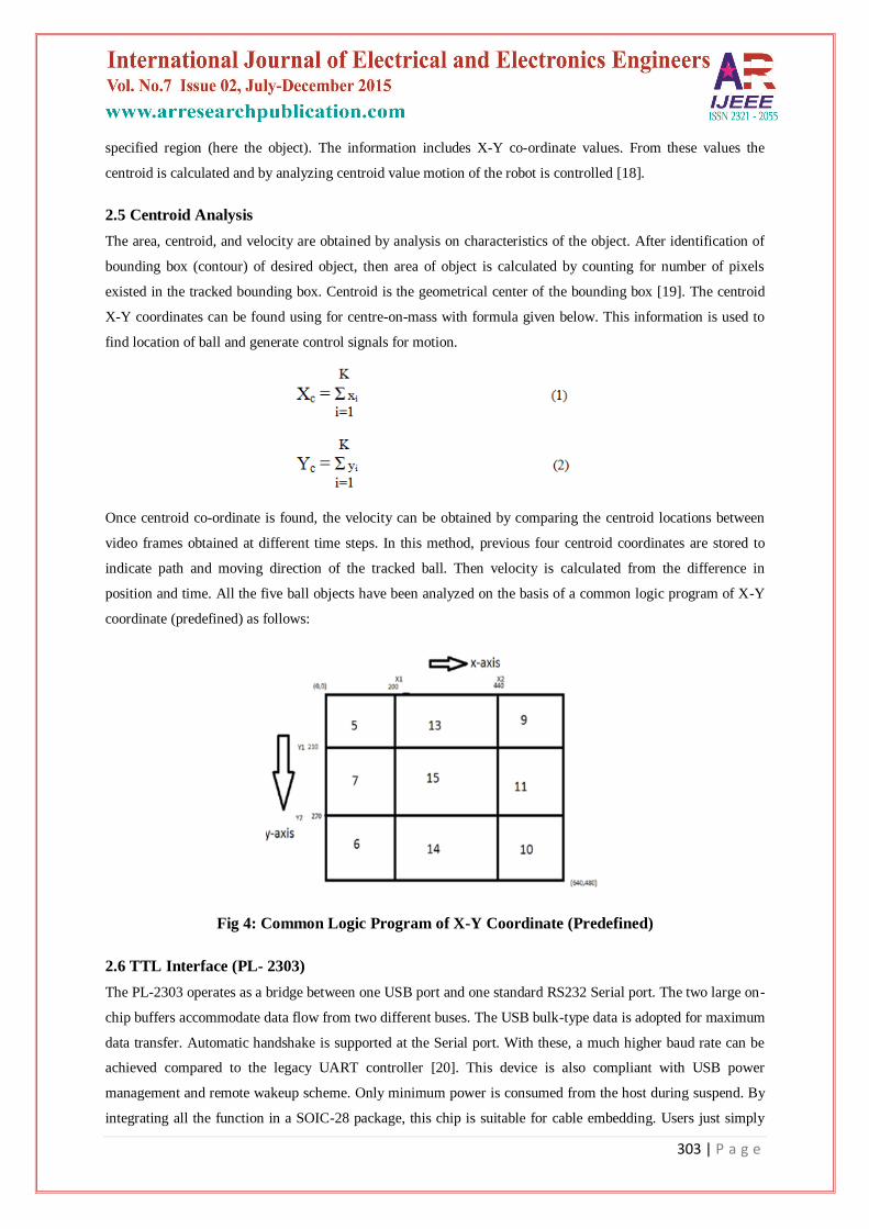
2.5 Centroid Analysis
The area, centroid, and velocity are obtained by analysis on characteristics of the object. After identification of
bounding box (contour) of desired object, then area of object is calculated by counting for number of pixels
existed in the tracked bounding box. Centroid is the geometrical center of the bounding box [19]. The centroid
X-Y coordinates can be found using for centre-on-mass with formula given below. This information is used to
find location of ball and generate control signals for motion.
Once centroid co-ordinate is found, the velocity can be obtained by comparing the centroid locations between
video frames obtained at different time steps. In this method, previous four centroid coordinates are stored to
indicate path and moving direction of the tracked ball. Then velocity is calculated from the difference in
position and time. All the five ball objects have been analyzed on the basis of a common logic program of X-Y
coordinate (predefined) as follows:
Fig 4: Common Logic Program of X-Y Coordinate (Predefined)
2.6 TTL Interface (PL- 2303)
The PL-2303 operates as a bridge between one USB port and one standard RS232 Serial port. The two large on-
chip buffers accommodate data flow from two different buses. The USB bulk-type data is adopted for maximum
data transfer. Automatic handshake is supported at the Serial port. With these, a much higher baud rate can be
achieved compared to the legacy UART controller [20]. This device is also compliant with USB power
management and remote wakeup scheme. Only minimum power is consumed from the host during suspend. By
integrating all the function in a SOIC-28 package, this chip is suitable for cable embedding. Users just simply

304 | P a g e
hook the cable into PC or hub’s USB port, and then they can connect to any RS-232 devices. PL-2303 allows
storing the configuration data in an external EEPROM. After reset, the first two bytes of EEPROM are checked.
If the value is 067Bh, the EEPROM is valid and the contents of the EEPROM are loaded as the chip’s default
parameters. Otherwise, the chip’s default setting is used.
2.7 Absolute Maximum Ratings
Item Ratings
Power Supply Voltage -0.3 to 6.0 V
Input Voltage -0.3 to VDD+0.3 V
Output Voltage -0.3 to VDD+0.3 V
Storage Temperature -55 to 150 oC
III. IMPLEMENTATION
The VSA (video structure analysis) in MATLAB (R2009b) of five different coloured and unlike sized balls
(size1-yellow colour, size2-orange colour, size3-white colour, size4-blue colour, size5-light blue patch white) is
described below:
The VSA (video structure analysis) of five different ball sizes were captured and analyzed in MATLAB. The
different ball size images were acquired using the Image Acquisition Toolbox and was carried out in following
steps.
Step 1: Acquire Image
Step 2: Calculate Sample Colors in L*a*b* Color Space for Each Region
Step 3: Classify Each Pixel Using the Nearest Neighbor Rule
Step 4: Display Results of Nearest Neighbor Classification
Step 5: Display 'a*' and 'b*' Values of the Labeled Colors.
3.1 Vsa of Ball Size 1 (Yellow Colour)
Fig 5: Plot obtained for pixel ‘a* ‘ Fig 6: Plot obtained for pixel ‘b*’

305 | P a g e
Fig 7: Graph depicting colour label Fig 8: Graph depicting colour marker
Fig 9: Graph depicting hidden purple colour in ball Fig 10: Graph showing label of ball
Fig 11: Scatter plot of segmented pixel in ball Fig12: Graph obtained of a*b* space for ball
Fig 13- Figure obtained of ball size 1 Fig 14- Figure obtained of ball size 1
(before dilation) (after dilation)

306 | P a g e
3.2 VSA of Ball Size 2 (Orange Colour)
Fig 15: Plot obtained for pixel ‘a* ‘ Fig 16: Plot obtained for pixel ‘b*
Fig17: Graph depicting colour label Fig18: Graph depicting colour marker
Fig 19: Graph showing label of ball Fig 20: Graph depicting hidden purple colour in ball
Fig21: Graph obtained of a*b* space ball pixel Fig 22: Scatter plot of segmented in ball
Fig 23- Figure obtained of ball size 2 Fig 24- Figure obtained of ball size 2
(before dilation) (after dilation)

307 | P a g e
3.3 VSA of Ball Size 3 (White Colour)
Fig 25: Plot obtained for pixel ‘a Fig 26: Plot obtained for pixel ‘b*’
Fig 27: Graph depicting colour label Fig 28: Graph showing label of ball
Fig 29: Graph depicting hidden purple colour in ball Fig 30: Graph depicting colour marker
Fig31: Graph obtained of a*b* space for ball Fig 32: Scatter plot of segmented pixel in ball
Fig 33: Figure obtained of ball size 3 Fig 34: Figure obtained of ball size 3
(before dilation) (after dilation)

308 | P a g e
3.4 VSA of Ball Size 4 (Blue Colour)
Fig 35: Plot obtained for pixel ‘a* ‘ Fig 36: Plot obtained for pixel ‘b*’
Fig 37: Graph depicting colour marker Fig 38: Graph depicting colour label
Fig 39: Graph showing label of ball Fig 40: Graph depicting hidden purple colour in ball
Fig41: Graph obtained of a*b* space for ball Fig 42: Scatter plot of segmented pixel in ball
Fig 43: Figure obtained of ball size 4 Fig 44: Figure obtained of ball size 4
(before dilation) (after dilation)

309 | P a g e
3.5 VSA of Ball Size5 (Light Blue Patch White)
Fig 45: Plot obtained for pixel ‘a* ‘ Fig 46: Plot obtained for pixel ‘b*’
Fig 47: Graph depicting colour label Fig 48: Graph depicting colour marker
Fig 49: Graph showing label of ball Fig 50: Graph depicting hidden purple colour in ball
Fig 51: Graph obtained of a*b* space for ball Fig 52: Scatter plot of segmented pixel in ball
Fig 53: Figure obtained of ball size 5 Fig 54: Figure obtained of ball size 5
(before dilation) (after dilation)

310 | P a g e
The mechanical structure is made up on hard plastic material. The hardware part constitutes robot connected
with TTL device which constitutes the robot mobility control and power supply of 12V (P-P), 1A; given by the
adaptor. The mobility controller used is a PIC microcontroller based embedded system. The USART program is
fed via a USB port to the microcontroller which decodes commands from the PC to set the serial communication
and later the user defined MATLAB program is utilized to track the dynamic position of the ball.
IV. RESULTS AND DISCUSSION
4.1 Problems Solved
a) Reflection from smooth ground plane can lead to false object identification. It is rectified by using any non-
reflective surface.
b). Reflecting surface of the tracked object which is avoided by eliminating plastic surface on tracked object.
c) Variation on surrounding illumination which is tackled by providing constant illumination level.
4.2 Problem Unsolved
a) Colour changing objects cannot be tracked.
b) Malfunction occurs while tracking objects having same colour and size.
Table I: Common robot response with different ball sizes movements styles
Sl No Position on ball in frame Robot Motion Centroid
1
No Motion
X=200-440
Y=210-270
2
Move Backward
X=200-440
Y=0-220
3
Move Left
X=0-200
Y=210-270
4
Move Right
X=440-640
Y=210-270
5
Move With ward
X=200-440
Y=270-480

311 | P a g e
V. CONCLUSION
The project is designed, implemented and tested successfully. The response of system to different object
movements was satisfactory. Still some advancement can be included to for system to improve performance.
Obstacle avoidance mechanisms can be included. This can be done by sensing the back ground images and
processing it properly. The mobile robot should have the abilities to follow a running human and avoid
dynamically moving obstacles in an unstructured outdoor environment.
VI. FUTURE ASPECTS
In the above proposed working model of ball tracking robot, the present block diagram may be modified by
including wireless interfacing and range detection as described below for future aspects:-
6.1 Wireless Interface
Wireless Transmission may be done by using ZigBee module. The serial communication between MATLAB
processer and microcontroller may be done through ZigBee module. ZigBee is a low-cost, low power, wireless
mesh networking standard [21]. This new level on communication permits finely-tuned remote monitoring and
manipulation. It focuses on ZigBee as a technology innovation which would bring about low cost connectivity.
ZigBee is a small, low-power digital radio. ZigBee is based on an IEEE 802.15 standard. Though low-powered,
ZigBee devices can transmit data over long distances by passing data through intermediate devices to reach
more distant ones.The ZigBee technology is widely used in wireless control and monitoring applications, for
low power-usage allows longer life with smaller batteries, and the mesh networking which promises high
reliability and larger range. ZigBee may be used to meet the growing demand with capable wireless networking
between numerous low power devices. ZigBee is used in applications that require only a low data rate, long
battery life, and secure networking. ZigBee has a data rate of about 250 kbit/s, best suited with periodic or
intermittent data or a single signal transmission from a sensor or input device. ZigBee networks are secured by
128 bit symmetric encryption keys. In home automation applications, transmission distances range from 10 to
100 meters line-on-sight, depending on power output and environmental characteristic.
6.2 Range Sensing
There are several methods to measure distance without any contact. One way is to use ultrasonic waves at 40
kHz for distance measurement. Using ultrasonic transducers and receiver we measure the amount on time taken
for a pulse on sound to travel to a particular surface and return as the reflected echo. Distance based on the
speed may be calculated distance may be measured up to 2.5 meters [22]. For range detection an ultrasound
transceiver may be used. The transmitter sends a burst at 40 kHz, which lasts with a period approximately
0.5ms. It travels towards the object through air medium and the echo signal is picked up by ultrasonic receiver
unit, also a 40 kHz pre-tuned unit. The received signal, which is very weak, is amplified several times using a
receiver circuit. Weak echoes may also occur due to signals being directly received through the side lobes.
These are ignored for real echo received and would give for correct distance. That is why we should have a level
control. The signal gets weaker if the target is more than 2.5 meters and will need a higher pulse excitation
voltage or a better transducer.
312 | P a g e
REFERENCES
[1] Wang J, Xu Y, Shum H Y, “Video tooning”. ACM Transactions on Graphics, 2004, 23 (3): 574-583.
[2] Zhang Y, Xiao J, Shah M,” Motion layer based object removal in videos”, in proceedings of the Seventh
IEEE Workshops on Application of Computer Vision (WACV/MOTION’05). Washington DC, USA:
IEEE Computer Society, 2005: 1: 516-521.
[3] T. Ishiguro and R. Miyamoto, “An efficient prediction scheme for pedestrian tracking with cascade
particle filter and its implementation on Cell/B.E,” in proceedings. Int. Symp. ISPACS, Jan. 2009, pp.
29–32.
[4] H. Medeiros, X. Gao, R. Kleihorst, J. Park, and A. C. Kak, “A parallel implementation of the color-
based particle filter for object tracking,” in proceedings. ACM SenSys Workshop Applicat. Syst
Algorithms Image Sensing (Image Sense), 2008.
[5] D. Cherng, S. Yang, C. Shen, and Y. Lu, “Real time color based particle filtering for object tracking
with dual cache architecture,” in proceedings. 8th IEEE Int. Conf. AVSS, Aug.–Sep. 2011, pp. 148–153.
[6] X. Lu, D. Ren, and S. Yu, “FPGA-based real-time object tracking for mobile robot,” in proceedings
ICALIP, 2010, pp. 1657–1662.
[7] S. Liu, A. Papakonstantinou, H. Wang, and D. Chen, “Real-time object tracking system on FPGAs,” in
proceedings. SAAHPC, 2011, pp. 1–7.
[8] Y.-M. Lin, C.-H. Yeh, S.-H. Yen, C.-H. Ma, P.-Y. Chen, and C.-C. Kuo, “Efficient VLSI design for SIFT
feature description,” in Proc. ISNE, 2010, pp. 48–51.
[9] H. El, I. Halym, and S. E.-D Habib, “Proposed hardware architectures of particle filter for object
tracking,” EURASIP J. Adv. Signal Process., vol. 2012, no. 1, p. 17, 2012.
[10] M. Garabini, A. Passaglia, F. Belo, P. Salaris, and A. Bicchi, “Optimality principles in variable stiffness
control: The VSA hammer,” in proceedings. IEEE/RSJ International Conference on Intelligent Robots
and Systems, Sept 2011, pp. 3770–3775.
[11] D. Braun, M. Howard, and S. Vijayakumar, “Optimal variable stiffness control: formulation and
application to explosive movement tasks,” Autonomous Robots, vol. 33, no. 3, pp. 237–253 2012.
[12] S. Haddadin, F. Huber, and A. Albu-Schaffer, “Optimal control for exploiting the natural dynamics of
variable stiffness robots,” in proceedings. IEEE International Conference on Robotics and Automation,
May 2012, pp. 3347–3354.
[13] I. Sardellitti, G. Medrano-Cerda, N. Tsagarakis, A. Jafari, and D. Caldwell, “Gain scheduling control for
a class of variable stiffness actuators based on lever mechanisms,” IEEE Transactions on Robotics, vol.
29, no. 3, pp. 791–798, 2013.
[14] Hou-Tsan Lee, Wei-Chuan Lin, Ching-Hsiang Huang, Yu-Jhih Huang,” Wireless Indoor Surveillance
Robot,” SICE Annual Conference 2011,Waseda University, Tokyo, Japan,September 13-18, 2011.
[15] Kyunghoon Kim, Soonil Bae, and Kwanghak Huh,” Intelligent Surveillance and Security Robot
Systems,”978-1-4244-9123-0/1 ©2010 IEEE.
[16] Jorg Kriiger, Bertram Nickday, Oliver Schulz, ” Image-Based 3D-Surveillance in Man-Robot-
Cooperation,”0-7803-8513 6/4/2004 IEEE.