a taxonomy of cyber attacks on 3g networksnsrc.cse.psu.edu/tech_report/nas-tr-0021-2005.pdf · a...
TRANSCRIPT

1
A Taxonomy of Cyber Attacks on 3G Networks
Kameswari Kotapati, Peng Liu, Yan Sun, Thomas F. LaPorta [email protected], [email protected], [email protected], [email protected]
The Pennsylvania State University, University Park, PA 16802 USAAbstract
Cross Network Services are a new breed of services that have spawned from the merger of the Internet and the previously isolatedwireless telecommunication network. These services act as a launching pad for a new type of security threat - the Cross InfrastructureCyber Attack. This paper is the first to propose attack taxonomy for 3G networks. The uniqueness of this taxonomy is the inclusion ofCross Infrastructure Cyber Attacks in addition to the standard Single Infrastructure attacks. This paper also proposes an abstract modelof the 3G network entities. This abstract model has been a vehicle in the development of the attack taxonomy, detection of vulnerablepoints in the network and validating 3G network vulnerability assessment tools. This paper examines the threats and vulnerabilities in a3G network with special examination of the security threats and vulnerabilities introduced by the merger of the 3G and the Internet. Theabstract model aids this comprehensive study of security threats and vulnerabilities on 3G networks.
1. Introduction
Early first and second generation (1G & 2G, respectively) wireless telecommunication networks were controlled byexchanging signaling messages on closed SS7 based networks. These networks were isolated because they did not provideconnectivity to any public networks to which end subscribers had direct access. The vulnerabilities of these networks werefew and well assessed. The vision of the next generation 3G wireless telecommunication network is to use IP technologies.3G networks will provide IP connectivity to its subscribers with the help of its IP Multimedia Subsystem. The IPMultimedia Subsystem will use IP to transport information, and Session Initiation Protocol (SIP) and Mobile IP for sessioncontrol and mobility management.
The introduction of IP technologies into traditional wireless telecommunication networks has opened up a newgeneration of IP-based services that must interwork with the 3G wireless telecommunication networks. These services arecalled Cross Network Services. Cross Network Services will use a combination of Internet-based data and data from thewireless telecommunication network to provide services to the wireless subscriber. They will be multi-vendor, multi-domain, and will cater to a wide variety of needs.
A security risk is introduced by providing Internet connectivity to 3G networks in that certain attacks can be easilyenforced on the wireless telecommunication network indirectly from the IP networks. These Cross Infrastructure CyberAttacks are simple to execute and yet have serious effects.
The threats and vulnerabilities introduced by merging these networks have not been studied or assessed. In this paperwe present a unique attack taxonomy, in which we consider the Cross Infrastructure Cyber attacks in addition to thestandard Single Infrastructure attacks, some of which have already been studied. To develop the attack taxonomy wederived an abstract model of the 3G network infrastructure. Other applications of this abstract model include detection ofvulnerable points in the network and validation of 3G vulnerability assessment tools. In this paper the abstract model isused to study the Cross Infrastructure Cyber Attacks and illustrate the taxonomy.
Existing literature identifies security threats, security scenarios, security problems and security requirements of thestandalone wireless telecommunication network. There is no available literature on Cross Infrastructure Cyber attacks andattack taxonomy. This paper expects to bridge the gap. Section 2 gives an overview of the 3G network, background andliterature survey. Section 3 explains the abstract model and Section 4 explains how these attacks are enabled. Section 5explains the taxonomy of attacks and Section 6 concludes. In the body of this paper we focus on the interaction of circuit-based 3G wireless networks and IP-based services. In Appendix B we discuss pure all-IP based networks.
2. Background
3G networks are designed to provide multimedia capabilities and high speed packet data service. The architecture of the3G Network is illustrated in Figure 2.1.The core 3G network may be accessed through a Radio Access network (also calledthe Air Interface) with 3G-enabled technology such as CDMA 2000 and WCDMA. The Core 3G network is connected tothe Internet and the PSTN (Public Switched Telephone Network). Internet connectivity enables 3G users to receive dataservices, such as weather reports, stock reports, sports information, chat, electronic mail; Cross Network Services such asCall Forwarding Services, Client Billing Service and Location Based Instant Messaging; Location Based Services such asnavigation, restaurant information, etc. In 2G systems network access is provided either to the PSTN or the Internet, soCross Network Services are unavailable.
The core 3G network is further divided into the Circuit Switched (CS) domain, the Packet Switched (PS) domain and theIP Multimedia Subsystem (IMS) based on the functional viewpoint. Deployment of the IP Multimedia Subsystem requiresthe deployment of the PS domain [2].

2
The Circuit Switched domain comprises of a set of all core network entities offering circuit switched type ofconnections for user traffic and related signaling. The CS Domain is used to access the PSTN. The CS domain entities aredescribed in Section 2.1.
The Packet Switched domain comprises of a set of all core network entities offering packet switched type of connectionfor user traffic and related signaling. The PS domain is used to access the Internet. The CS and PS domain may have someentities in common [3].
The IP Multimedia Subsystem comprises of a set of all core network entities for provision of multimedia services. TheIMS enables the mobile network operators to offer their subscriber’s multimedia services based on and built upon Internetapplications, services and protocols. The IMS entities are described in Appendix B.1. The SIP (Session Initiation Protocol)protocol may be used for multimedia session control in the IMS [2]. The IMS is the ultimate goal to provide IP Services toits subscribers.
In this paper we describe access of IP based services to wireless telecommunication subscribers through interaction withthe CS domain of the 3G network. This interaction will provide a migration path for CS networks to IMS and it will likelybe used for several decades as CS networks remain in existence. It is the combination of IP services and CS networks thatenables the Cross Network Services and Cross Infrastructure Cyber Attacks. Readers interested in IP based servicesinteracting with the IP Multimedia subsystem may read Appendix B.
In the next two subsections we will discuss 3G network entities, Cross Network Services and Cross Infrastructure Cyberattacks.
2.1 Core 3G Network
Subscribers may be affiliated with two networks in a 3G system: a home network and a serving network. Everysubscriber is permanently assigned to the home network. The responsibilities of the home network include provision ofservices to the subscriber, management and maintenance of subscriber profiles, billing and authenticating the subscriber toreceive service. The serving network changes as the user location changes. It provides radio resources, mobilitymanagement, routing and handling services for the subscribers. The Serving Network capabilities are provided to thesubscribers on behalf of the home environment, with which the serving network has an appropriate agreement [13]. Thereare four main entities in the CS domain and are described below.
All subscribers are permanently assigned to a fixed Home Location Register (HLR). The HLR is said to be in the homenetwork. The HLR stores permanent subscriber profile data and relevant temporary data such as current subscriber location(pointer to VLR) [5].
Visitor Location Register’s (VLR) are assigned to a specific administrative area and associated with one or moreMSC’s. The VLR acts as a temporary repository and stores data of all mobile stations (user handset) that are currentlyroaming in its assigned area. The VLR obtains this data from the HLR assigned to the mobile station [5].
The Mobile Switching Center (MSC) acts as an interface between the radio system and the fixed network. It is assignedto a fixed administrative area. It performs all necessary functions in order to handle the circuit switched services to andfrom the mobile stations roaming into its area. The MSC is in-charge of functions related to registration, mobilitymanagement, paging, handover etc. The VLR and MSC could be either in the home network, if the subscriber is located inthe home network, or the serving network if the subscriber roams into another location area [5].
If a network delivering a call to the mobile network cannot interrogate the HLR, the call is routed to an MSC. This MSCwill interrogate the appropriate HLR and then route the call to the MSC where the mobile station is located. The MSC incharge of routing the call to the actual location of the mobile station is called the Gateway MSC (GMSC). The GMSC’s areavailable to pass voice traffic between the PSTN network and the 3G network [5]. For description of the IMS entities referto Appendix B.1.
For the 3G networks to provide service to the subscriber some of the above-mentioned entities must perform certainfunctions. These functions may be triggered by the arrival of signaling messages. Hence it can be said that the 3G networkprovides the subscriber service through the exchange of signaling messages among its entities. Signal 1 in Fig 4.1 is anexample of a signaling message. Some of the 3G entities have data stores associated with them. These data stores maintainthe data used by the 3G entities. The entity manages the data store by sending database queries to the data store. Databasequeries 2a, 2b in Fig 4.1 are examples of a database queries.
2.2 Cross Network Services and Attacks
We define Cross Network Service as a new generation of IP-based services that must interwork with the 3G wirelesstelecommunication networks. Cross Network Services will use data from the IP network and data from the wirelesstelecommunication network to provide services to the wireless subscriber. We describe three examples of Cross NetworkServices below.

3
In the Email Based Call Forwarding Service (CFS) the status of the subscriber’s email inbox is used to trigger callforwarding in the wireless telecommunication network. E.g. calls from a certain peer group that have emails pending in thecalled party’s inbox for longer than a certain period of time are delivered to voice mail; calls from a second peer group areimmediately delivered to the cell phone. Call delivery is via the 3G network.
In the Client Billing Service (CBS) the caller id of an incoming call is used to trigger a client billing system, which willforward the call and bill the client appropriately. Lawyers or Agents in an Insurance Agency may use such a Client BillingService to bill clients for the telephone advice or services offered.
In the Location Based Instant Messaging System (LB-IM), a location track request from a buddy triggers the core 3Gnetwork to locate the subscriber. This location is revealed only if the buddy belongs in a location visibility group and a timevisibility group. After the location is known the requestor can begin instant messaging. An example of the LocationVisibility Group is that a supervisor may locate colleagues at work. An example of the Time Visibility Group is thatcolleagues and supervisors at a work place can view location between 9 am and 5 pm on weekdays.
Single Infrastructure Attacks are attacks on a domain from the same network domain, e.g., the attacker has gainedaccess into a core 3G network entity and attacks other 3G network entities.
Cross Infrastructure Cyber Attacks may be defined as attacks on the wireless telecommunication network from the IPdomain. These attacks use Cross Network Services as an entry point into the wireless telecommunication network. We willnow illustrate such an attack with the help of the abstract model and a simplified version of the Email Based CallForwarding Service. In the following discussion, we refer to the abstract model detailed in Section 3.
The simplified version of the CFS works by forwarding a call to the voice mail if there is no email from the caller;otherwise the call is forwarded to the subscriber’s cellular phone. Every one-hour the CFS Mail Server Agent in the CFServer will fetch emails stored in the Post Office data source of the Mail Server. This data is stored in Email data cache ofthe CFS. When there is an incoming call for the CF subscriber, the Subscribed Services Support Agent in the MSC willquery the CF Server on how to forward the call. The CFS Filtering Agent will check its Email data cache, and if there is anemail from the caller, the call is forwarded to the subscriber’s cellular phone.
The propagation of the attack from the Mail Server to the CF Server and finally the 3G network entity is illustrated inFig 2.2. Using any standard Mail Server vulnerabilities the attacker may compromise the Mail Server and corrupt the PostOffice data source by deleting emails from certain people from whom the victim is expecting calls. The CFS Mail ServerAgent queries the Mail Transaction Agent for emails from Post Office data source and the Mail Transaction Agent will passon the corrupted email data to the CFS Mail Server Agent. The CFS Mail Server Agent will cache the email data in itsEmail data cache. The Email data cache will be corrupted and the effect of the attack on the Mail Server has propagated tothe CF Server. When the Subscribed Services Support Agent in the MSC entity of the 3G network sends out a ‘how toforward the call’ query to the CF Server, the CF Server will check its corrupt Email data cache and find that there are noemails from the caller. The CF Server will reply to the Subscribed Services Support Agent to forward the call to the voicemail when in reality the call should be forwarded to the cellular phone. Thus the effect of the attack on the Mail Server haspropagated to the 3G network. This is a classic example of a Dimension: I-Level V Cross Infrastructure Cyber Attack,where the attacker gains access to the Cross Network Server and attacks by modifying data in the data source of the CrossNetwork Server. Detailed information of the various Dimensions and Levels may be found in Section 5.
Figure 2.1: Architecture of a 3G network Figure 2.2: Attack Propagation in CFS with simplified abstract model

4
2.3 Literature Survey
Telecommunication standards [13,14,15] specify 3G security and identify certain security threats. They includingeavesdropping, masquerading, traffic analysis, browsing, compromising authentication vectors, manipulation of messages,disturbing or misusing network services, denial of service, resource exhaustion, misuse of privileges and abuse of services.Such papers [11,12,17,19,25] have identified single infrastructure threats or attack scenarios on 3G networks while trying toprove the inadequacy of current security schemes or presenting a new architecture or guidelines for 3G security. The attackscenarios identified in these papers include masquerade, unauthorized notification of resources, line-tap attacks,eavesdropping, man in the middle, guessing attack, replay attacks, interleaving attack and they have been included in ourtaxonomy.
Threats, vulnerabilities and attack scenarios on the SS7 domain are identified in [9,10,24]. An attack taxonomy for SS7network entities is defined in [9]. The classification in [9] groups attacks based on the SS7 entity (Service Switching Points,Signal Transfer Point and Service Control Point) under attack. The need for security is motivated in [21]. The securityfeatures available in current 3G networks are discussed in [22,23,26]. In conclusion of this survey, we find that attacks onthe SS7 networks are well studied and documented with an attack taxonomy. Some attacks on the core 3G networks arewell studied but there is no existing attack taxonomy. We define an attack taxonomy to fill this void. The uniqueness of thistaxonomy is the inclusion of Cross Infrastructure Cyber Attacks.
3. Abstract Model
We have defined an abstract model to better understand and classify the attacks that may be possible on the 3G network.The abstract model has been constructed for relevant 3G network entities. Every network entity performs a number ofsophisticated functions that have been divided into a number of basic, simple atomic functions. Each network entity hasbeen divided into atomic functional units called Agents. Each of these basic, simple atomic functions is assigned to anAgent. Network entities manage some data. This data may be permanent or temporarily cached from another networkentity. Every network entity also has Service Logic. The Service Logic coordinates interactions between the differentAgents and data inside the network entities. Fig 3.1 shows the schematic representation of abstract model elements.
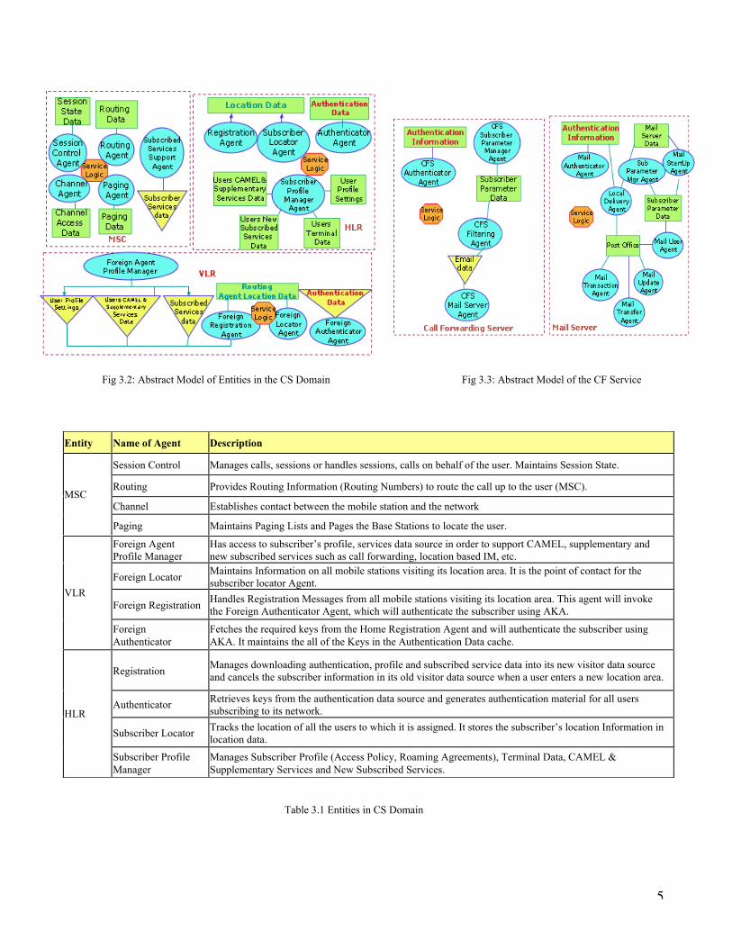
Fig 3.2 shows the abstract model of the entities in the CS domain. Table 3.1 describes the agents used in CS Domainabstract model. Fig 3.3 shows the abstract model of the CF Service; it includes the CF Server and the Mail Server. Table3.2 describes the agents used in the Mail Server. Table 3.3 describes the agents used in the CF Server. Fig 3.4 shows theabstract model of the LB-IM Service. Table 3.4 describes agents in LB-IM Server. Fig 3.5 shows abstract model of the CBSService. Table 3.5 describes agents in CBS Server.
With the help of the abstract model, it is straightforward to pinpoint security threats, vulnerabilities and attacks atspecific points in 3G infrastructures. For example, if outgoing links from the HLR are compromised and if the caller id inthe signaling message 8 of Figure 4.1 is changed, then calls to a subscriber may not be routed to the appropriate CF Server.If the caller is an important person, he may be very unhappy to get the voice mail and the victim subscriber may sufferfinancial losses as a result of not receiving the call.
Fig 3.1: Elements used in the abstract model
5
Table 3.1 Entities in CS Domain
Fig 3.2: Abstract Model of Entities in the CS Domain Fig 3.3: Abstract Model of the CF Service
Entity Name of Agent Description
Session Control Manages calls, sessions or handles sessions, calls on behalf of the user. Maintains Session State.
Routing Provides Routing Information (Routing Numbers) to route the call up to the user (MSC).
Channel Establishes contact between the mobile station and the networkMSC
Paging Maintains Paging Lists and Pages the Base Stations to locate the user.
Foreign AgentProfile Manager
Has access to subscriber’s profile, services data source in order to support CAMEL, supplementary andnew subscribed services such as call forwarding, location based IM, etc.
Foreign LocatorMaintains Information on all mobile stations visiting its location area. It is the point of contact for thesubscriber locator Agent.
Foreign RegistrationHandles Registration Messages from all mobile stations visiting its location area. This agent will invokethe Foreign Authenticator Agent, which will authenticate the subscriber using AKA.
VLR
ForeignAuthenticator
Fetches the required keys from the Home Registration Agent and will authenticate the subscriber usingAKA. It maintains the all of the Keys in the Authentication Data cache.
RegistrationManages downloading authentication, profile and subscribed service data into its new visitor data sourceand cancels the subscriber information in its old visitor data source when a user enters a new location area.
AuthenticatorRetrieves keys from the authentication data source and generates authentication material for all userssubscribing to its network.
Subscriber LocatorTracks the location of all the users to which it is assigned. It stores the subscriber’s location Information inlocation data.
HLR
Subscriber ProfileManager
Manages Subscriber Profile (Access Policy, Roaming Agreements), Terminal Data, CAMEL &Supplementary Services and New Subscribed Services.

6
Fig 3.4: Abstract Model of the LB-IM Service Fig 3.5: Abstract Model of the CBS Service
Table 3.2 Entities in Mail Server
Name of Agent DescriptionSubscriber ParameterManager Agent
Manages all of the parameters set by the subscriber
Filtering Filters data retrieved by the Mail Server Agent/ Phone Book Agent based on parameters set by a subscriber andinstructs the Mail Server Agent/ Phone Book Agent to retrieve more information.
Mail ServerAgent
Interfaces Mail Server with Call Forwarding Server. It will query Mail Server based on subscriber parametersand retrieve information
Authenticator Maintains Subscriber Authentication Data and will know the address of the 3rd party used to authenticate thesubscriber.
Table 3.3 Entities in CF Server
Name of Agent DescriptionSubscriber ParameterManager Agent
Manages all of the parameters set by the subscriber.
Mail Starting Retrieves Subscribers Parameter Settings & Mail Server Data and Invoke Mail Transfer Agent when asubscriber starts the Mail Service.
Local Delivery Takes care of mail that is to be delivered to a local user
Mail Transaction Agent Allow queries to the incoming mail storage (Post Office) and retrieves the result
Mail User Agent Allows the user to compose and read e-mail messages. This agent acts as an interface between the user andthe Mail Transfer Agent.
Mail Update Agent Manages the state of the incoming mail storage in the Post Office.
Mail Transfer Agent Transfers e-mail messages from one computer to another. This agent is responsible for delivering outgoingmail and receiving incoming mail.
Authenticator Responsible for authenticating subscribers wanting to access the Mail Server and all other servers that contactthe Mail Server with a request .

7
Table 3.4 Entities in LB-IM Server
Name of Agent Description
Subscriber ParameterManager Agent
Manages all of the parameters set by the subscriber
Time Agent Times the call and saves in as a part of the clients account
Forwarding Forward the call to the appropriate party
Bill Calculator Calculates the bill, based on Time logged and other constraints
Mail ServerAgent
Interfaces Mail Server with Call Forwarding Server. It will query Mail Server based on subscriberparameters and retrieve information
Authenticator Maintains Subscriber Authentication Data and will know the address of the 3rd party used to authenticatethe subscriber.
Table 3.5 Entities in CBS Server
For the abstract model of the IMS, refer to Appendix B.2. Appendix B.2 also has Table B.1 with a description of theIMS entities.
4. Attack Overview
4.1 What makes attacks possible on the 3G Network?
Early 1G and 2G wireless telecommunication networks and the PSTN networks were closed as signaling messages wereexchanged on private isolated SS7 based networks. These isolated networks were not connected to any public networks andhence malicious hackers could not gain easy access into the wireless telecommunication network. The attacks that werepossible on these isolated networks were well studied and have been considered in our taxonomy. An example of whatmakes these attacks possible is the easy availability of standard inexpensive “off-the-shelf” mobile radio test equipment.This equipment could be used to impersonate parts of the network. Other threats are disgruntled employees and terroristswho can gain access into central offices and into 3G core network entities.
With the integration of the core 3G networks, the PSTN and the Internet, the networks have opened up additionalvulnerabilities and provided malicious attackers easy access through the Cross Network Servers. The Internet is open andaccessible to one and all with simple equipment. It is also very easy for malicious attackers to break into Internet serversdue to many vulnerabilities [27]. Breaking into an Internet server providing Cross Network Service opens up possibilitiesfor the attacker to invade the 3G core and PSTN networks. The Cross Infrastructure Cyber Attack is easy to execute andmay be serious enough to cause the breakdown of the telecommunication network. Some examples of Cross NetworkServices that act as a launching pad for the Cross Infrastructure Cyber Attacks are the Call Forwarding Service (CFS), theLocation Based-Instant Messaging (LB-IM) and the Client Billing Services (CBS). In the following discussion, we refer tothe agents at data sources summarized in Tables 3.1-3.5.
The CFS and CBS Services are triggered when a signaling message arrives at the Subscriber Locator Agent (HLR)assigned to the subscriber. The Subscriber Locator Agent will send a database query to its User Terminal data source andfind the terminals registered for the user, and will subsequently query the Location Data Source and find the ForeignLocation Agent (VLR) where the subscriber is registered. The Foreign Locator Agent will invoke the Routing Agent (MSC)to provide a routing number to route the call to the Session Control Agent (MSC) where the subscriber is currently roaming.The routing number is returned to the Subscriber Locator Agent (HLR). The call is routed to the Session Control Agent(MSC). The Session Control Agent (MSC) will invoke the Subscriber Services Support Manager (MSC) to check if there
Name of Agent DescriptionSubscriber Parameter ManagerAgent
Manages all of the parameters set by the subscriber.
Request Manager Agent Receives Requests to view subscriber location and services them.
IM Manager Agent In charge of sending out location track requests to members on the buddy listLocation Tracking Agent Responsible for tracking the location of the user by querying the 3G network and it maintains current
location data of the subscriber
Authenticator Responsible for authenticating subscribers /networks wanting to access the LB-IM Server and all otherservers that contact the LB-IM with a request.

8
are any Cross Network Services listed for the call receiver. The Subscriber Services Support Manager (MSC), through aquery of cached Subscribed Services Data from the HLR, is aware that the call receiver subscribes to the CFS and CBSservices.
Fig 4.1 shows the signal flows for detecting caller id based Cross Network Services. The Subscriber Services SupportManager (MSC) fetches, through an internal query of its database, parameters need to invoke the CFS/CBS, and willrequest the Authenticator Agent (HLR) to authenticate with the Cross Network Server. This is shown in Fig 4.2 for the CFSand Fig 4.4 for the CBS. In services such as the CBS and the CFS where the caller id is used to determine the type ofservice to be provided, only the serving network (MSC/VLR) can invoke the Cross Network Service. We assume that thesubscriber does not subscribe to any other supplementary service and hence the caller id is only available in the signalingmessage received at the MSC and not the HLR.
Fig 4.1: Signal Flows: Cross Network Services for Incoming Calls
If the Cross Network Server is the CFS, after the authentication, the CFS Subscriber Parameter Manager Agent invokesthe CFS mail Server agent to checks its cached email data store to see if it satisfies any constraints set by the user. Emailsin the cached email data store is fetched from the Mail Server by the CFS Mail Server Agent at intervals set by thesubscriber shown in Fig 4.3. Depending on the constraints set by the subscriber and the email cache from the CFS MailServer Agent, the CFS Filtering Agent returns the forwarding number to the Subscriber Services Support Manager (MSC),which will invoke other network entities to forward the call. Fig 4.2 shows the above signaling flows. In the CFS CrossNetwork Service, the Cross Infrastructure Cyber Attacks can occur at the Mail Server and the CF Server itself.
Fig 4.2: Signal Flows: Provide CFS for Incoming Call Fig 4.3: Signal Flows: The CF Server fetching Emails from Mail Server
If the Cross Network Server is the CBS, after the authentication, the CBS Client Checker Agent checks if a clientcorresponding to the caller id exists in Client Phone book data store. If there is a match, the CBS Forwarding Agent isinvoked which will forward the call to the appropriate number and invoke the CBS Timer Agent. When the call is over the

9
CBS Bill Calculator will calculate the billing amount. Fig 4.4 shows the signaling flows for the above process. In the CBSCross Network Service, the Cross Infrastructure Cyber Attacks can occur at the CB Server.
The LB-IM is triggered when a location track request arrives at the LB-IM Request Manager. The LB-IM RequestManager will check if the requestor belongs in the location and time visibility group by checking the Permissions datastore. If the requestor satisfies the constraints, the LB-IM Location Tracking Agent fetches the location of the subscriber byquerying the 3G network entities.
4.2 How do attacks on 3G networks occur?
Attacks may occur from various points in the network. Broadly attacks may be divided into Single Infrastructure andCross Infrastructure Cyber Attacks.
Most Single Infrastructure Attacks will be launched from the air interface of the 3G networks. These may be originatedusing standard inexpensive “off-the-shelf” mobile radio test equipment to impersonate parts of the network [11]. Theintruder can analyze traffic, eavesdrop, intercept signaling messages, modify signaling messages and jam the radiointerface.
If an attacker breaks into a 3G core network entity itself, the attacker can insert, modify and destroy data sources so thatmalicious subscribers may commit subscription fraud, collect confidential information from other entities and modifyservice logic to disrupt the network operation, thereby denying service. However, it is very difficult to break into a core 3Gnetwork entity.
Breaking into an Internet Server providing a Cross Network Service opens up possibilities for the attacker to executeCross Infrastructure Cyber Attacks. We will now consider how attacks can happen using the above Cross Network Servicesexamples.
With CFS attacks can occur at the Mail Server or CF Server. Attacks at the Mail Server enabled, using vulnerabilities atthe Mail Transfer Agent such as a badly configured sendmail daemon. The attacker can send emails with a fake source id tothe victim; the CF Server will assume that it is checking the correct constraints, but in reality the victim may receiveunwanted calls and have important calls sent to voice mail.
Other attacks may be launched if the attacker gains privileges to modify the service logic. Modification of time andother settings in the service logic would result in the Mail Transaction Agent replying to queries from CFS Mail ServerAgent with zero emails, when in reality there may be a number of emails.
Attacks at the CF server include, sending spoofed messages to the CFS Subscriber Parameter Manager Agentrequesting a change in parameters, or by gaining privileges to modify the email cache and subscriber preferences andcausing a denial of service by flooding the CFS Authentication Agent.
With the CBS, attacks can occur at the CB Server. Attacks include a denial of service on the CBS Authentication Agent,or obtaining privileges to modify the Timer Agents, Bill Calculator Agents and Forwarding Agents. Such attacks may resultin the victims receiving large bills and unable to receive service on time.
With the LB-IM service, spoofed messages may be sent to the LB-IM Subscriber Parameter Manager Agent requestinga change in permissions resulting in invasion of the victim’s privacy and disturbance from unwanted parties.
Fig 4.4: Signal Flows: Provide CBS for Incoming Call Fig 4.5: Signal Flows: Handling LB-IM request

10
5. Attack Taxonomy
In the following subsections we present a formal taxonomy of attacks on 3G Networks.
5.1 Taxonomy of Attacks on 3G Networks
In order to devise a taxonomy of attacks on the 3G Network, we consider the attacker’s physical access to the network,the type of attack categories and the means used to cause the attack. We classify the attacks into three dimensions:Dimension I: Physical Access to the Network, Dimension II: Attack Categories and Dimension III: Attack Means.
5.1 Dimension I: Physical Access to the Network
In this dimension, attacks are classified based on the level of physical access the attacker has to the 3G wirelesstelecommunication network. Dimension I may be further classified as Single Infrastructure Attack (Level 1-III) and CrossInfrastructure Cyber Attack (Level IV-V):
Level I: Access to air interface with physical device: The attacker has access to standard inexpensive “off-the-shelf”equipment that could be used to impersonate parts of the network [11]. The attacker may put up a false base station.Victims camping on the false base station are subject to false base station attacks. Attackers may also use modified mobilestations to broadcast at a high frequency, eavesdrop and cause a man in the middle attack.
Level II: Access to Cables connecting Central Offices (3G core network entities): The central offices house the 3G corenetwork entities. Typically authorized personnel only may access these central offices. If the attacker has access to cablesconnecting these central offices. They may cause damage by disrupting normal transmission of signaling messages.
Level III: Access to 3G core network entities in the Central Office: In this case the attacker may be a disgruntledemployee or a terrorist who has managed to gain access into the central office. Here the attacker can cause damage byediting the service logic or modifying subscriber data (profile, security and services) stored in the network entity.
Level IV: Access to Links connecting the Internet and the 3G core network: This is a Cross Infrastructure Cyber Attack.The attacker has access to links connecting the 3G-core network and the Internet based Cross Network Services. In this casethe attacker can cause damage by disrupting normal transmission of signaling messages traversing the link and insertingsignaling messages into the link between the two networks. Level IV may be sub divided based on the interworkingapproaches used to connect the 3G core network and the Internet. Appendix A details the various interworking approachesand attacks.
Level V: Access to Internet Servers or Cross Network Servers (provides multimedia or other services to mobilesubscribers) connected to the 3G networks: This is a Cross Infrastructure Cyber Attack. In this case the attacker can causedamage by editing the service logic, modifying subscriber data (profile, security and services) stored in the Cross NetworkServers. This level of attack is easier to achieve Level II and Level III.
5.1.1 Dimension II: Attack Categories
In this dimension, attacks are classified based on type of attack. The attack categories are based on [30].
Interception: The attacker intercepts information e.g., reads signaling messages on a cable (Level II), but does notmodify or delete them. This is a passive attack. This affects the privacy of the subscriber and the network operator. Theattacker may use the data obtained from interception to analyze traffic and eliminate the competition provided by thenetwork operator.
Fabrication/Replay: In this case the attacker may insert spurious objects into the system. These objects depend on thelevel of the attackers physical access to the system. E.g.: In a Level II, the attacker may insert fake signaling messages, in aLevel III, the attacker may insert fake service logic or fake subscriber data into this system. The effects could result in theattacker masquerading as an authority figure.
Modification of Resources: The attacker causes damage by modifying system resources. E.g.: In a Level II, the attackermay modify signaling messages in and out of the cable. In a Level III, the attacker may modify service logic or modifysubscriber data in the entity.
Denial Of Service: The attacker causes an overload or a disruption in the system such that network functions in anabnormal manner. The abnormal behavior could be legitimate subscribers not receiving service, illegitimate subscribersreceiving service or the entire network may disabled as a result of the attack.
Interruption: The attacker caused an Interruption by destroying resources. E.g.: In a Level II, the attacker may deletesignaling messages in and out of the cable. In a Level III, the attacker may delete a subscriber data in the entity such as anHLR and the attacker may not receive service.

11
5.1.2 Dimension III: Attack Means
In this dimension, attacks are classified based on what means are used to cause the attack. The attack means are asfollows.
Data: The attacker attacks the data stored in the system. Damage is inflicted by modifying, inserting and deleting thedata stored in the system.
Messages: The attacker attacks the system through the signaling messages. The attacker may insert, modify, delete andreplay signaling messages going in and out of the network.
Service Logic: The attacker inflicts damage by attacking the service logic running in the various 3G core networkentities. E.g.: Interruption attack on service logic would be to completely delete the logic running on an entity such as theMSC.
5.2 Attacks
In this section we will use the classification detailed in Section 5.1 to group attacks. The attacks are tabulated as CASE1: Dimension 1-Physical Access Vs Dimension II-Attack Categories and CASE 2: Dimension II-Attack Categories VsDimension II1-Attack Means. Note that the Dimension I vs. Dimension III CASE can be transitively inferred from CASE 1and CASE 2.
We tabulate a list of possible attacks on the CS Domain. Table 5.1 shows the CASE 1 tabulation of possible SingleInfrastructure attacks on the CS domain. Table 5.2 shows the CASE I tabulation of possible Cross Infrastructure Cyberattacks. Table 5.3 shows attacks classified by CASE II. Interested readers may view Appendix B.4 for attacks on the IPMultimedia Subsystem.
A Cross Infrastructure Cyber Attack can be comprised of a single stage or multiple stages. In a multistage CrossInfrastructure Cyber Attack each stage can belong to different attack categories (Dimension II) and can use different attackmeans (Dimension II). Cross Network Servers offer services in multiple phases. Each service phase may be subject to aCross Infrastructure Cyber Attack stage. The effects caused by an attack on a single phase of this service can have direct orindirect effects on the next service phase and can result in a multi stage attack. A number of these single stage attacks whenexecuted in sequence can form a multi stage Cross Infrastructure Cyber Attack. We now present some examples of singlestage Cross Infrastructure Cyber Attacks outlined in Table 5.2.
Call forwarding Service (CFS): Level IV attacks on the CF Service may be enumerated as follows. In Interceptionattacks, the attacker may view caller-id’s of calls to a victim and sell this information. The attacker may also view the callforward number and track the whereabouts of the victim. The attacker may view the authentication messages and use it fora replay attack later on. The attacker may also view emails fetched by the CF Server from the Mail Server and gain accessto the victim’s personal information.
In the Insertion/Fabrication attack, the attacker can bombard the CF server with Call Forward requests and can causea denial of service. The attacker can send a large number of authentication requests to the CF and Mail Servers and cause adenial of service attack. The attacker may also request email messages from the Mail Server with the help of theauthentication messages captured early on.
In the Modification attack, the attacker can modify parameters in the messages, e.g. caller id so that the calls areforwarded incorrectly, modify the call forward number, change the authentication challenge response to incorrect value sothe CF and Mail servers are never authenticated. In the Interruption attack, the attacker may delete all messages on thelink arriving to the CF Server or Mail Server giving an impression that these servers are not functional.
Level V attacks on the CF Service may be enumerated as follows. In the Interception attack the attacker may stealpersonal information of subscribers stored in the Subscriber Parameter data store of the CF or Mail Server. In theInsertion/Fabrication attack, subscribers not paying for the service may be inserted into the CF Subscriber Parameterdata sources. At the CF Server fake email data may be inserted into the Email data cache through the CFS Mail ServerAgent. In the Modification attack, the attacker may also have the capability to modify call forward numbers for subscriberat the Subscriber Parameter data store, change the time stamps of cached Email data, replace service logic in the CFSFiltering Agent and the CFS Mail Server Agent.
Denial of Service may be caused by the changing the CF number since the victim does not gain access to the voicemessage or the call itself. Sending two or three call forward numbers to the Session Control Agent at the MSC may causeconfusion and the call may not be handled properly. In the Interruption attack, the attacker may delete certain targetsubscriber profiles in the data sources so that they may not receive CF service. At the Mail server, the emails in the Postoffice data store may be deleted. Service logic of certain entities may be completely deleted such as the CFS Filtering Agentso that they may be unable to provide any service.
Client Billing Service (CBS): Level IV attacks on the CB service may be enumerated as follows. In Interceptionattacks, the attacker may view caller id's of calls to a victim and sell this information. The attacker may view theauthentication messages and use it for a replay attack later on. In the Insertion/Fabrication attack the attacker can

12
bombard the CB server with Bill Client Requests and can possibly cause a denial of service. The attacker can send a largenumber of authentication requests to the CB Server and cause a denial of service attack.
In the Modification attack, the attacker can modify parameters in the messages, e.g. caller id so that the calls areforwarded incorrectly, change the authentication challenge response to incorrect value, the CB servers are neverauthenticated. In the Interruption attack, the attacker may delete all messages on the link arriving to the CB Server givingan impression that these servers are not functional.
Level V attacks on the CB Service may be enumerated as follows. In the Interception attack the attacker may stealpersonal information of subscribers stored in the client preferences data source in CB Server. In the Insertion/Fabricationattack, subscribers not paying for the service may be inserted into the CB data source or fake charged may be inserted intoa victim’s bill.
In the Modification attack, the attacker may also have the capability to modify the forward numbers for subscriber orcorrupt logic in CBS Timer Agent and CBS Bill Calculator; this results in the victim receiving exorbitant bills. Attack theCBS Client Checker Agent; change the bill amount or the time log of the client’s consultation. Denial of Service may becaused by changing the CF number or simply removing the victims name from the client phone book. In the Interruptionattack, the attacker may corrupt the phone book and delete victims from the Client Phone Book data source so that theymay not receive CF service.
Location Based Instant Message System (LB-IM): Level IV attacks on the LB-IM Service may be enumerated asfollows. In Interception attacks, the attacker may view location track requests and location in the location track responsesviolating privacy. The attacker may view the authentication messages and use it for a replay attack later on. In theInsertion/Fabrication attack the attacker can bombard the LB-IM server with location track requests and can possiblycause a denial of service.
The attacker can send a large number of authentication requests to the LB-IM Server and cause a denial of serviceattack. In the Modification attack, the attacker can modify parameters in the messages, e.g. name of buddy in the locationtrack request and the location where the buddy is located or change the authentication challenge response to incorrect valueso the LB-IM server is never authenticated. In the Interruption attack, the attacker may delete all messages on the linkarriving to the LB-IM Server giving the impression that this server is not functional.
Level V attacks on the LB-IM Service may be enumerated as follows. In the Interception attack the attacker may stealpersonal information of subscribers stored in the Permissions and Buddy list data store of the LB-IM. In theInsertion/Fabrication attack, subscribers not paying for the service may be inserted into the LB-IM permissions andbuddy list data sources. At the LB-IM server authentication information may be inserted to authenticate fake core networkentities.
In the Modification attack, the attacker may also have the capability to modify permissions and buddy list data stores,E.g. the victim's boss may be able to view the victim’s weekend locations. The service logic in the LB-IM request managermay be modified so that the requests are not properly checked. Changing the Buddy list and permissions so that legitimatemembers of the list cannot locate the subscriber thereby cause Denial of Service. In the Interruption attack, the attackermay delete certain target subscriber profiles in the data sources so that they may not receive LB-IM service. Service logic ofcertain agents may be completely deleted.
6. Conclusion
This paper has defined a unique attack taxonomy for 3G networks, which includes the Cross Infrastructure Cyberattack. As more vulnerabilities are discovered, the taxonomy may be expanded to support newer attacks. The abstractmodel defined in this paper has been instrumental in the development of the 3G attack taxonomy. We have demonstratedthat with the help of the abstract model, it is straightforward to pinpoint security threats, vulnerabilities and attacks atspecific points in 3G the infrastructure. In the future it can be shown that the abstract model may be used to validate 3Gvulnerability assessment tools.

13
*AV: Authentication vector
Table 5.1: Single Infrastructure attacks on the CS domain classified by CASE 1.
Interception Fabrication/Insertion
ModificationOf Resources
Denial OfService
Interruption
LevelI
-Observe time,rate, length, sourceand destination ofvictim’s locations.-With modifiedMS, eavesdrop onvictim.
- When target camps atfalse base station, callsmade by the victim maybe hijacked and used tomake fraud calls, whilethe victim is charged.
- With modified basestation and modifiedmobile station, theintruder can comebetween the target andthe network
- When victims camp atfalse base stations, thenvictims are out of reach ofsignals from the servingnetwork and can nolonger receive calls andother network relatedservices.
-Jam victims trafficchannels so the victimcannot access thechannel. -Broadcast at a higherintensity than allowedhogging bandwidth
LevelII
-Analyze trafficpatterns, gathersubscriber/company data-Eavesdrop oncalls and voicesignalingmessages-Capture AV’ssent from HLR toVLR and use inreplay attacks.
- Send a large number ofrouting requests to theRouting Agent (MSC):exhaust RN’s, so the MSCcannot support more callrequests.- Send Registration /Location Updatemessages to RegistrationAgent (HLR) to causeincorrect call routing,shutting down of themobile station’s- Send profile changemessages to: SubscriberProfile Manager AgentAt HLR: Subscriber maynot receive services.- Request AV’s fromHLR: AuthenticatorAgent and use for replayattacks
- Change called partynumber in call requestmessages and the callis sent to incorrectparty.-Change the routingnumbers in routingresponses, so MSCunder attack does notreceive incomingcalls.- Change the AV’ssent to authenticatethe MS, so that theMS is neverauthenticated.
- Send IAM to switch/MSC: exhaust RN’s :Overload Switch- Large number of authrequest to authenticatorAgentAt HLR slow down HLRand surrounding links.- Send spoofed LocationUpdate messaged to HLR: Registration Agent causeincorrect call routing,shutting down MN-Changing ProfileSettings: SubscriberProfile Manager Agent atHLR
-Delete Registration /Loc Update Messagesat Registration Agent(HLR) results inincorrect call routing- Delete Call Requests- Delete SendauthenticationInformation Requests
LevelIII
-Analyze trafficpatterns, gathersubscriber/company dataarriving at thecompromisingentity-Gather data storedin HLR and sell itto competition-At MSC, track thesubscriber’sactivities, calls andtheir services theyaccess.
Access to HLR: Add newsubscribers to the ProfileSetting, Terminal Data,Subscribed Services andCAMEL &Supplementary ServicesData stores and not thebilling data store, this waythe fraud subscribers canaccess the serviceswithout paying.- Insert new service logicto the compromised entityso that it is disabled at aparticular time.
-Change SubscriberProfile, Authenticationdata, location data atthe HLR.-Change the mappingat HLR: Locationdata: RegistrationAgent-Modify the routingnumbers in theRouting Agents. Callscannot be routed to theSession ControlAgents.
-Modify a parameter inthe Authentication Vectorcalculating algorithm sothat none of the MS’s maybe authenticated andhence do not get service.
- Delete subscriberpreferences- At AuthenticatorAgent HLR, deleteCiphering algorithmand replace withanother one, fail toauthenticate all MN.

14
Interception Fabrication/Insertion
Modificationof Resources
Denial OfService
Interruption
LevelIV
-Analyze trafficpatterns, gathersubscriber/companydata- View details ofmessages betweenthe Cross NetworkServers and 3G corenetwork entity.
- Send profile changemessages to CrossNetwork Servers:Subscriber ProfileManager Agent- Send a large numberof authenticationrequests to the CrossNetwork Servers.-Bombard the CrossNetwork Servers withrequests.
-Modify messagespassing on the link: Change thechallenge responseto incorrect value:device is neverauthenticated.: Change replies toqueries to incorrectvalues.: Modify parametersin the signalingmessages.
- Send the MSC:Session ControlAgent/ SubscribedServices SupportAgent a large numberof replies for aparticular query orspoof it to be queriesfor differentsubscribers.- Send the CrossNetwork Serverslarge number ofAuthenticationRequests and slowthem down
- Delete all messagesarriving and leavingthe Cross NetworkServers
LevelV
-Analyze trafficpatterns, gathersubscriber/company data- Steal personalinformation ofsubscribersregistered. ServiceLogic at the CrossNetwork Servers.
- Insert subscribers notsubscribed for serviceinto the Cross NetworkServers, they receiveservice but are notcharged.- Insert fake data intothe data stores of theCross NetworkServers.
-Modify ServiceLogic and datasources in the CrossNetwork Servers.
- Caused by editingthe data sources.
- Delete data sourcesand service logic inthe Cross Networkservers.
Table 5.2: Cross Infrastructure Cyber attacks classified by CASE I

15
AttackCategories
Data Messages Service Logic
Interception
- Gather customer information byreading data stored in database. Atthe Cross Network Servers invokeSubscriber Parameter manager Agent
-Analyze traffic patterns, gathersubscriber/company data
- Gather system information byobserving/reading operations inthe system-At the Cross Network Serversinvoke read the service logic
Insertion/Fabrication
-Add users to the database that are notsubscribed/ paying for the service.-At the Cross Network Servers invokeSubscriber Parameter manager Agentto insert into the SubscriberParameter Data Store
- Send a large number of routingrequests to the Routing Agent(MSC): exhaust RN’s, so the MSCcannot support more call requests.- Send Registration / LocationUpdate messages to RegistrationAgent (HLR) to cause incorrect callrouting, shutting down of the mobilestation’s - Send profile changemessages to Subscriber ProfileManager at HLR- Request AV’s from AuthenticatorAgent at HLR
-Insert new service logic to thecompromised entity so that it isdisabled at a particular time.
Modificationof Resources
- Modify Subscriber profileInformation so that the subscriberreceives services he is not paying for.(E.g.: Receive National wide servicewhen subscribed for local service.)-Remove subscribers name fromdatabase. (E.g.: Deny Service forthose already registered)
-Modify messages passing on thelink: Change the challenge response toincorrect value: device is neverauthenticated.: Change replies to queries toincorrect values.
-Modify Service Logic : Fwd Calls to wrong Location : Change Call Forwarding Logic : Show Wrong Buddiessubscriber Location Information:Service Logic in request IM: Change E-mail Time Stamps:Service Logic Mail Server: Client Phone Book: ClientChecker Agent
Denial ofServices
-Deny Service for those alreadyregistered by removing subscribersname from database: Invoke theRegistration Agent
- Send Multiple Challenges toAuthenticator Agent at HLRrequesting authentication for multipleusers. This could clog the HLR.- Send the MSC: Session ControlAgent a large number of replies for aparticular query or spoof it to bequeries for different subscribers
- Modify Service Logic : Fwd Calls to wrong Location :Change Call Forwarding Logic
Deletion /Interruption
- Delete subscriber data/ Subscriber preferences stored in theCross Network Server : Mail Data : Phone Book Data : CF Data : Buddy List
- Delete all messages arriving at theCross Network Server : CF messages-Delete all messages leaving theCross Network : Challenges to HLR : Response to queries (MSC)
- Delete service logic CrossNetwork Server : CF rules set by the subscriber:CFS Subscriber ParameterManager agent. : CBS service logic : Permissions and Buddy list LB-IM Subscriber Parameter Manageragent.
Table 5.3: Attacks classified by CASE 1I

16
7. References
[1] Andrew P. Snow, Upkar Varshney, Alisha D. Malloy, "Reliability and Survivability of Wireless and Mobile Networks",IEEE Computer, July 2000, p. 49-55.[2] 3GPP TS 23.221, "Architectural requirements", V6.3.0 (2004-06).[3] 3GPP TS 23.002 V3.3.0 (2000-03), Network architecture (Release 1999).[4] 3GPP TS 23.228 V6.7.0 (2004-09), IP Multimedia Subsystem (IMS); Stage 2 (Release 6)[5] Eberspacher, Vogel, “GSM Switching, Services and Protocols”, John Wiley & Sons, Copyright 1999.[6] 3GPP TS 23.008 V3.3.0 (2000-03), Organization of subscriber data (Release 99)[7] C. W. Blanchard, "Wireless Security", BT Technology Journal, v.19 n.3, p.67-75, July 2001[8] 3GPP TS 23.018 V 3.4.0 (2000-03), Basic Call Handling (Release 99)[9] G. Lorenz, T. Moore, G. Manes, J. Hale, S. Shenoi, “Securing SS7 Telecommunications Networks”, Proceedings of the2001 IEEE Workshop on Information Assurance and Security, June 2001[10] T. Moore, T. Kosloff, J.Keller, G. Manes, S. Shenoi, “Signaling System 7 (SS7) Network Security,” Proceedings ofthe IEEE 45th Midwest Symposium on Circuits and Systems, Tulsa, OK, August 4-7, 2002.[11] Howard, P. Walker, M. Wright, T., “Towards a coherent approach to third generation system security”, SecondInternational Conference, 3G Mobile Communication Technologies, 2001. on (Conf. Publ. No. 477)[12]El-Fishway, Nawal A.; Nofal, Mostafa A.; Tadros, Albert M., "An Improvement on Secure Communication inPCS",Performance, Computing, and Communications Conference, 2003. Conference Proceedings of the 2003 IEEEInternational , 9-11 April 2003[13] 3G TS 21.133 V3.1.0 (1999-12) 3G Security; Security Threats and Requirements version 3.1.0[14] 3G TR 33.900 V1.2.0 (2000-01),A Guide to 3rd Generation Security[15] 3G TS 33.120 V3.0.0 (1999-05) 3G Security; Security Principles and Objectives version 3.0.0[16] J.Rao, P. Rohatgi, H. Scherzer, S. Tinguely, “Partitioning Attack: Or How to Rapidly Clone Some GSM Cards”, IEEESymposium on Security and Privacy, May 2002.[17] CC Lo and YJ Chen, “Secure communication mechanisms for GSM networks,” IEEE Transactions on ConsumerElectronics, Vol. 45, No. 4, pp..[18] A. Chakrabarti and G. Manimaran, "Internet Infrastructure Security: A Taxonomy," IEEE Network, vol.16, no.6,pp.13-21, Nov/Dec. 2002.[19] Donald Welch ,Scott Lathrop, "Wireless Security Threat Taxonomy”, June 2003 IEEE Workshop on InformationAssurance.[20] C. W. Blanchard, "Wireless Security", BT Technology Journal, v.19 n.3, p.67-75, July 2001[21] Brookson, C.B.,"Security in current systems", Security in Networks (Digest No. 1995/024), IEE Colloquium on , 3Feb. 1995,Pages:3/1 - 3/6.[22] Mitchell, C.J.;"Security in Networks",(Digest No. 1995/024), IEE Colloquium on , 3 Feb. 1995 ,Pages:2/1 - 2/6.[23] Boman K, Horn G, Howard P,Niemi V, "UMTS security", Electronics & Communication EngineeringJournal, Volume: 14 , Issue: 5 , Oct. 2002, Pages:191 - 204[24] Kluepfel, H.M.,"Securing a global village and its resources: Baseline security for interconnected Signaling System #7telecommunications networks"Security Technology, 1993. Security Technology, Proceedings. IEEE 1993 InternationalCarnahan Conference on , 13-15 Oct. 1993,Pages:171 - 188.[25] Clissmann, C., Patel, A., "Security for mobile users of telecommunication services", Universal PersonalCommunications, 1994. Record., 1994 Third Annual International Conference on , 27 Sept.-1 Oct. 1994,Pages:350 - 353.[26] V. Bharghavan, C.V. Ramamoorthy, "Security Issues in Mobile Communications", Autonomous DecentralizedSystems, 1995. Proceedings. ISADS 95., Second International Symposium on , 25-27 April 1995.[27] http://www.kb.cert.org/vuls/id/125235[28] CERT Advisory CA-97.05: "MIME Conversion Buffer Overflow in Sendmail Versions 8.8.3 and 8.8.4"at:http://www.cert.org/advisories/CA-97.05.sendmail.html[29] Sendmail Consortium: "Sendmail FAQ” http://www.sendmail.org/faq [30] Stallings, “Cryptography and Network Security: Principles and Practice”, Second Edition, Copyright 2000.[31] K. Murakami, O. Haase, J. Shin, T. F. LaPorta. Mobility Management Alternatives for the Migration to MobileInternet Session-based Services. In IEEE Journal on Selected Areas in Communications (J-SAC), special issue on MobileInternet, Vol. 22, No. 5, Jun 2004.[32]Amit P. Sheth , James A. Larson,” Federated database systems for managing distributed, heterogeneous, andautonomous databases”, ACM Computing Surveys, Vol. 22, No. 3, pp. 183-236, Sep. 1990.

17
Appendix A - Interworking Approaches
In this section we identify attack scenarios in the methods used to interwork the 3G core network and the Internet.Based on the interworking approaches we will modify the attack taxonomy and group the attacks.
A.1 Background
In this section we discuss the three approaches for interworking the core 3G networks and the Internet. ProtocolGateway Approach, Federated Approach and the Unified Approach are the three basic approaches and they are described indetail below [31].
Protocol Gateways: Protocol Gateways are components used to connect disparate networks by passing traffic betweenthe two networks. The Protocol Gateway performs the protocol conversion and routes traffic; every network receives trafficin the protocol it understands. E.g. In Fig A.1, the Protocol Gateway converts 3G Traffic to IP Traffic and vice versa.
Fig A.1: Protocol Gateway connecting the core 3Gand IP Networks.
Fig A.2: Core 3G and IP Network entities in a FederatedRelation
Federated Approach: In the Federated Approach, entities in the core 3G and the IP networks communicate throughtheir data sources. Entities in the federated approach share their data sources with other entities while maintaining somemeasure of local control. Component data sources can operate independently, but can also give up their autonomy toparticipate in the federation. Entities in a federated relationship communicate by exchanging queries between data sourcesinstead of signaling messages between the entities. These database queries will traverse the links connecting the twonetworks. Fig A.2 displays the federated relationship. E.g. In Fig 4.2 the “Authenticate” signal message 14 exchangedbetween the Authenticator Agent (HLR) and CFS Authenticator Agent may be replaced by an exchange between the HLR-Authentication Data and CFS-Authentication Information data sources in the Federated Approach. Cross Network signalingmessages are replaced by Cross Network data source queries [32].
Fig A.3: Interworking Core 3G and IP Network entities with UMM

18
Unified Approach: The unified approach introduces a network element called the Unified Mobility Manager (UMM).The UMM contains a multiprotocol subscriber database which maintains the subscriber profile information for all servicesand all network types to which the user subscribes. The UMM also has an internal protocol translator which translates fromone protocol to another [31]. E.g. UMM multiprotocol subscriber database stores data from HLR; Cross Network servicessuch CF services, LB-IM services etc. Figure A.3 shows the interworking using the UMM approach. Cross Networksignaling queries are sent to the UMM, which looks up its multiprotocol subscriber database to check if the query is valid.If this query is valid the signaling messages goes through the protocol translator and is sent to the other network.
A.2 Attack Taxonomy and Attacks
This section examines the changes in attack taxonomy and groups attacks in the three interworking approaches.
A.2.1 Protocol Gateways
In this Approach, Dimension I-Level IV may be further divided into Level IV a and Level IV b. In Level IV a theattacker has Access to Links connecting the Internet and the 3G core network, it is the same as Level IV in Section 5.1.1.and in Level IV b the attacker has Access to Protocol Gateway.
Level IV b : Access to Protocol Gateway: When the attacker has access to the Protocol Gateway the attacker may viewthe messages passing through the links, insert messages into the links and corrupt the protocol translator or service logic.
We will use the above classification to detail attacks. The attacks are tabulated as CASE 1: Dimension 1: PhysicalAccess Vs Dimension II: Attack Categories. Table A.1 shows the CASE 1 tabulation of possible attacks with theintroduction of the protocol gateways. In Table A.1 we will consider the effect of Dimension I-Level III access on theProtocol Gateway, effect of Level IV b access and the effect of Dimension I-Level V access on the Protocol Gateway.
Table A.1: Attacks classified by CASE 1 Protocol Gateway Approach.
A.2.2 Federated Approach
In this Approach, Dimension I-Level IV definition remains the same when compared to the other interworking cases. Inthis case database queries traverse the links instead of signaling messages. The attacker can cause damage by disruptingnormal transmission of database queries traversing the link and inserting database queries into the link between the twonetworks.
We will use the above classification to detail attacks. The attacks are tabulated as CASE 1: Dimension 1: PhysicalAccess Vs Dimension II: Attack Categories. Table A.2 shows the CASE 1 tabulation of possible attacks with the Federated
Interception Fabrication/Insertion
ModificationOf Resources
Denial OfService
Interruption
LevelIII
-Analyzetrafficpatterns,gather dataaround PGW.
- Insert large number ofmessages requesting CrossNetwork Services andHence Protocolconversion: OverloadGateway.
- By causing a bufferoverflow attack modify thecontents/service Logic ofProtocol Gateway
- Repeated Requestsfor Cross NetworkServices.
-By causing a bufferoverflow attack deletethe contents/serviceLogic of ProtocolGateway
LevelIV b
-ViewMessagesarriving atthe gateway
-Insert messages into thelink requesting for CrossNetwork Services and 3G-core services
-Modify routing tables sothat the converted traffic isrouted to the Intruder’snetwork-Modify parameters in theprotocol conversion logic,the converted traffic isgarbled : Service is notprovided
-Deletion/Do notprovide responses ofRequests that arriveat the PGW.
-Insert Large number ofmessages on the link.
LevelV
-AnalyzeTrafficPatterns
- Insert large number ofmessages requesting 3Gcore services
-Remote access the ProtocolGateway causing a bufferoverflow
- Repeated Requestsfor 3G Services.
-By causing a bufferoverflow attack deletethe contents/serviceLogic of ProtocolGateway

19
approach. In Table A.2 we will consider the effect of Dimension I-Level III access on Federated relation, effect of Level IVaccess and the effect of Dimension I-Level V access on Federated relation.
Table A.2 : Attacks classified by CASE 1 Federated Approach.
A.2.3 Unified Approach
In this Approach, Dimension I-Level IV may be further divided into Level IV a and Level IV b. In Level IV a theattacker has Access to Links connecting the Internet and the 3G core network, it is the same as Level IV and Level IV b isAccess to Unified Mobility Manager.
Level IV b : Access to Unified Mobility Manager: When the attacker has access to the Unified Mobility Managerattacker may view the messages passing arriving at the UMM, access the data in the multiprotocol subscriber database,access the protocol translator logic. The attacker may insert messages into the links and corrupt the multiprotocol subscriberdatabase, protocol translator or service logic.
We will use the above classification to detail attacks. The attacks are tabulated as CASE 1: Dimension 1: PhysicalAccess Vs Dimension II: Attack Categories. Table A.3 shows the CASE 1 tabulation of possible attacks with theintroduction of the Unified Mobility Manager. In Table A.3 we will consider the effect of Dimension I-Level III access onthe Unified Mobility Manager, effect of Level IV b access and the effect of Dimension I-Level V access on the UnifiedMobility Manager.
Interception Fabrication/Insertion
ModificationOf Resources
Denial OfService
Interruption
LevelIII
-Analyzetrafficpatterns,gather data.-Eavesdropon messages
- Send a large number ofdata queries to CrossNetwork entities.-Insert fake data into thedatabase such that it isdisseminated to otherentities.-Send messages to otherentities and gathersensitive data from theirdatabases.
- Modify SubscriberInformation.- Modify access rulesin the federatedrelation so that validqueries are deniedaccess.-Modify dataconversion rules
- Modify Port addresses sothe entity may not bereached by other entities inthe federated relation.- Send a large number ofmessages and clog thedatabase port.-Modify mapping betweensubscriber profile andsettings (preferences,authentication); validqueries are denied.-Open up ports in 3Gentities, making itvulnerable to other attacks.
- Delete the contentsof the database.-Deny data access toother valid entities inthe federated relation.
LevelIV
-Analyzetrafficpatterns,gather data.-Eavesdropon messages
- Insert spoofed Request/Response type ofdatabase queries to thedatabases to gathersensitive information.
- Modify all databasequeries on the link.-Modify source,destination address,query, response.
- Direct database ports ofentities in the federationwith Service requests andclog the ports and the links.
-Deleting signalingqueries on link.- Send SpoofedMessages to cancelservice.-By deleting databaseresponses, the sourcewill continue to queryand overload thedestination.
LevelV
-Analyzetrafficpatterns,gather data.-Eavesdropon messages
- Send fake responsemessage (Just respondand not process themessages).- Send SpoofedMessages to 3G entitieslike HLR, VLRrequesting a specificservice such as processan incoming call.
-Modify parameterused for protocolconversion inwrappers.-Modify Requests.- Modify ServiceLogic so that multipleresponses are sentinstead of a single one.
- Repeated Requests for IPServices.-Change authenticationinformation at the CrossNetwork Servers , so thatcertain people are neverauthenticated and neverreceive any service.-Open up ports in CrossNetwork Servers, making itvulnerable to other attacks.
-Modify service logicso that the IP ServiceServer only respondsto every 2nd or 3rd
message

20
Table A.3: Attacks classified by CASE 1 UMM Approach.
Interception Fabrication/Insertion
ModificationOf Resources
Denial OfService
Interruption
LevelIII
-Analyze trafficpatterns, gatherdata.-Eavesdrop onmessagesarriving at theentities.
- Send large numberof messages to theCross NetworkServers, so that theUMM is overloaded.
- Send messages to theUMM requesting forchange in a 3Gsubscriber’s profile inthe multiprotocolSubscriber database.
- Repeated Requests forIP Services to theUMM.
-Delete 3G subscriberprofile data in themultiprotocolsubscriber database.
LevelIV b
-Analyze trafficpatterns, gatherdata.-Eavesdrop onmessagesarriving at theUMM
-Insert invalidsubscriber profileinto themultiprotocolSubscriber database.-Insert fakemessages on thelinks.
- Modify multiprotocolsubscriber database,query does not gothrough- Modify protocoltranslator such thatsignaling messages arenot translated right.-Modify the CrossNetwork signalingmessages passingthrough the UMM
-Delete subscriberprofile from themultiprotocolSubscriber databaseattached to the UMM;this way legitimatesubscribers do notreceive cross networkservice.
-Delete Messagesarriving at the UMM.-Delete data in themultiprotocolsubscriber database.-Delete the protocoltranslation logic sothat signal messagesare not translated.
LevelV
-Analyze trafficpatterns, gatherdata.-Eavesdrop onmessagesarriving at theentities.
- Send large numberof messages to theCross NetworkServers, so that theUMM is overloaded.
- Send messages to theUMM requesting forchange in a CrossNetwork subscriber’sprofile in themultiprotocolSubscriber database.
- Repeated Requests for3G Core Services to theUMM.
-Delete CrossNetwork Servicesubscriber profile datain the multiprotocolsubscriber database.

21
Appendix B: IP Multimedia Subsystem
B .1. Background
In this section we discuss the four main core network entities used in the IP multimedia subsystem.
Every network operator assigns in its administrative areas one or more P-CSCF’s (Proxy-Call Session ControlFunction). The P-CSCF is the first point of contact for a mobile station into the IMS network. The P-CSCF accepts requestsfrom the mobile station and either services them or forwards them on. It will locate the subscriber’s home network and is incharge of QOS reservation based on local network conditions and capabilities [4,7].
Every network operator has one or more I-CSCF(Interrogating-Call Session Control Function) assigned to its network.All messages in and out of the network must pass through the I-CSCF. This entity acts as a firewall and will hide thenetwork’s configuration, capacity and topology from the outside. The I-CSCF is the first point of contact into the networkfrom the outside world for incoming messages (Requests from subscribers roaming in other networks). All messagesexiting the network must pass through the I-CSCF [4,7].
The S-CSCF (Serving-Call Session Control Function) is located in the home network of the subscriber and is assignedat the time of registration depending on the needs of the subscriber. At the time of registration the subscriber service profileis downloaded from the HSS to the S-CSCF. It maintains the session state information as needed by the network operator tosupport services [4,7].
The subscriber’s IMS service settings, profile data, authentication data is defined and maintained in the HSS (HomeSubscriber Server). The HSS also maintains information of all S-CSCF’s in its domain.
The Session Initiation Protocol Uniform Resource Identifier (SIP:URI) is the generic form of address of a Internet baseduser (E.g., SIP User) or Internet resource. URI’ includes URL’s and Email Address.
B. 2. Abstract Model for IP Multimedia Subsystem
Fig B.1 shows the abstract model of the entities in the PS domain. The abstract model for the IMS shows the abstractmodel for the User Agent. The User Agent is a part of the mobile station. The User Agent contains data needed by the corenetwork and agents that interact with the network to provide service to the subscriber. Table B.1 describes the agents usedin IP Multimedia System Abstract Model.
Fig B.1: Abstract Model of Entities in the IP Multimedia Subsystem Fig B.2: Signal Flows IMS requesting LB-IM service

22
B.3 Attack Overview
In this section we will use the abstract model to study the initiation of the LB-IM service by the IP MultimediaSubsystem and discuss the attack possibilities on the IP Multimedia Subsystem. The LB-IM is triggered when a locationtrack request arrives at the LB-IM Request Manager. Fig B.2 shows the IMS signal flows requesting for LB-IM Service.This is an expansion of the 3G IMS cloud in Fig 4.5. In Fig B.2 the User Session Agent in the User Agent sends a LocationTrack Request into the serving network Proxy Session Control Agent(P-CSCF). The serving network Subscriber homedomain Data Manager(P-CSCF) stores the address of the Session Control Agent(S-CSCF), which is assigned at the time ofregistration. The Session Control Agent (S-CSCF) remains the same for the length of the registration. The Subscriber HomeDomain Data Manager (P-CSCF) looks into its Home Domain Data Source to find the address of the Session ControlAgent (S-CSCF). Once the Proxy Session Control Agent (P-CSCF) gets the address of the Session Control Agent (S-CSCF)it forwards the Location Track Request to the Session Control Agent. The Session Control Agent (S-CSCF) looks into itscached Subscriber Services data source and Subscriber Profile data source to check the subscriber’s profile and thesubscriber’s services data. If the Session Control Agent (S-CSCF) finds the request to be valid, it will request the ServingAuthentication Agent (S-CSCF) to authenticate with the LB-IM Authentication Agent. Once authenticated the SessionControl Agent (S-CSCF) forwards the Location Track request to the LB-IM Request Manager and the request will beserviced.
In the LB-IM Service spoofed messages may be sent to the LB-IM Subscriber Parameter Manager as mentioned inSection 4.1. Other possible attacks include corrupting the Home Domain data source so that the Session Control Agent maynot be located, corrupting the Subscriber Services data source and Subscriber Profile data sources. Section B.4 providesmore information on these attacks.
B.4 Attacks
We tabulate a list of possible attacks on the IMS Domain. Table B.1 shows attacks on IMS Subsystem classified byCASE 1. Level I of Attacks on the IMS Subsystem is the same as Level I of Attacks on the CS Domain (Table 5.1) hencewe are omitting it from Table B.1. In IMS Subsystem, Dimension I-Level III may be further divided into Level III a andLevel III b. In Level III a the attacker has Remote access to IMS entities and Level III b the attacker has Direct access toIMS entities. Level III b it is the same as Level III in the CS Domain. Cross Infrastructure Cyber Attacks of Level VI andV are similar to the CS domain shown in Table 5.2.

23
Table B.1: Description of Agents used in IMS Abstract Model
Entity Name of Agent Description
User Authenticator Manages Authentication data (secret key, algorithm etc) stored in the mobile node.
Resource Reservation Based on incoming/outgoing session descriptors and its own terminal capabilities it will decide theresources needed for the session.
Signaling Channel Establishes contact between the mobile station and the network
Media Flows Will start/initiate media flows for a session based on terminal capabilities
User Session Will Initiate/Handle Incoming Sessions on behalf of the User.
UserAgent
User Registration It is invoked when a mobile node powers up or enters/exits a new area. This invokes the registration at thevisiting network.
SA Negotiator Negotiates Security Association with the User Agent.
Address Resolver Resolves URI’s to IP Addresses
QOS ResourceAuthorizer
It will approve/authorized the QOS resource reservation request based on current network load and radiolink capacity.
Proxy SessionControl Agent
Handles Incoming & Outgoing Sessions for a Users currently registered with the visiting network.
Subscriber HomeDomain Data Manager
Will save address of the visiting subscriber’s assigned session control agent for that registration.
P-CSCF
Foreign Registration It is the Registration Agent in the Visiting Network and is invoked by the user registration agent
Home Registration Receives registration messages at the entry point into the home network.
Address Resolver Resolves URI’s to IP Addresses
Home Session It will handle sessions for a user and forward messages between session control agent and proxy sessioncontrol agent.
I-CSCF
S-SCSF/SessionAgent Selector
It will select session control agent for the registered subscriber based on subscriber’s requirements andsession control agent capabilities.
Serving Authenticator Manages authentication data cached from the home network and performs the 3-way AKA.
Session Registration Handles subscriber registration by caching user profile data, services data from home domain and storeshome domain address locally and provide home domain the address of the assigned session control agent.
S-CSCF
Session Control Handles Sessions for the user in the Home network. Performs Service Control based on subscriber’s profile& subscribed services data.
Authenticator Is in charge of retrieving keys from the authentication data source and generating authentication materialfor all users subscribing to its network and also other services the user may be subscribed to. It may beinvoked to authenticate the subscriber
Subscriber RegistrationAgent
Handles all registration messages, checks if the user is already registered, if the user is allowed to registerin the Visiting Network and will contact the Authenticator to authenticate the user.
Session ControlAgent Data Manager
Manages data of all the S-CSCF/Session Control Agent in the network.
HSS
Update Tracker Will inform the assigned Session Control Agent if the user profile settings or services data.

24
PhysicalAccess
InterceptionFabrication/Insertion
Modificationof Resources
Denial OfService Interruption
Level II
LinksConnecting
IMSEntities
-Analyzetraffic patterns,gathersubscriber/company data-Eavesdrop oncalls and voicemessages-Capture AV’ssent fromAuthenticatorAgent (HSS) toS-CSCF(ServingAuthenticatorAgent) and usein replayattacks.
- Send repeated INVITEmessages to S-CSCF(Session Control Agent):overload Home Network,this way it cannot servicevalid incoming requestsand generate outgoingrequests.- Send Registration /Location Updatemessaged to SubscriberRegistration Agent(HSS): cause incorrectcall routing, shuttingdown MN- Send profile changemessages to HSS(Session Control AgentData Manager)- Request AV’s fromAuthenticator Agent(HSS)
-Change the SIP:URI[Uniform resource identifier](IMS User Address) inRegistration signalingmessage so that thesubscriber cannot beregistered.-Change the other party'sSIP:URI address in outgoingINVITE service requestsignaling messages and therequest is sent to incorrectparty.-Change the SIP:URIaddresses in the IncomingSession Invite Messages;message does not reach thesubscriber-Change the AV’s sent toauthenticate the User Agent,so that the User Agent isnever authenticated.
- Send repeatedINVITE messages to S-CSCF (Session ControlAgent): overloadHome Network.- Large number of authrequest toAuthenticator Agent(HSS) slow downAuthenticator Agentand surrounding links. - Send repeatedRegistration / LocationUpdate messaged toSubscriber RegistrationAgent (HSS): causeincorrect call routing,shutting down MN- Send profile changemessages to HSS(Session Control AgentData Manager).
-Delete Registration/ Location Updatemessaged toSubscriberRegistration Agent(HSS): incorrectcall routing- Delete Call InviteRequests- Delete AV’s sentfrom AuthenticatorAgent (HSS) to S-CSCF (ServingAuthenticatorAgent) Sendauthentication-Delete RingingMessages
LevelIII a
RemoteConnection
ToIMS
Entities
-Analyzetraffic patterns,gathersubscriber/company dataarriving at thecompromisingentity
- Insert new servicelogic to the compromisedentity so that it directs alltraffic to the Intrudersservice location.
- Buffer overflow attackscause execution of maliciouscode and hence modificationof Service Logic.
-Buffer overflow couldalso cause a denial ofService at the IMSEntity.
-Delete data sourcesin the entities.
LevelIII b
DirectConnection
ToIMS
Entities
-Gather datastored in entityand sell it tocompetition-Track aparticularsubscribersactivities at theSessionControl Agentand Datasources in theHSS
- Insert new service logicto the compromisedentity so that it isdisabled at a particulartime.-Access to HSS : Addnew subscribers to theProfile Setting,Subscribed Data storesand not the billing datastore, this way the fraudsubscribers can accessthe services withoutpaying.
-Modify destination ofSession Invite Messages.-Modify Session Descriptors -Change Subscriber Profile,AV, location mapping at S-CSCF & HSS data sources- Modify the sessionhandling capabilities at theSession Control Agent andProxy Session ControlAgent.-Modify Service Logic inSubscriber Home DomainManager so that UserSession Control Agentmapping is corrupted and theusers requests may not beserviced.
-Modify a parameter inthe AuthenticationVector calculatingalgorithm so that noneof the MS’s may beauthenticated and hencedo not get service.
- Delete subscriberpreferences- At AuthenticatorAgent (HSS), deleteCiphering algorithmand replace withanother one, fail toauthenticate all MN.- Delete subscriberpreferences
Table B.1: Attacks on IMS Subsystem classified by CASE 1