a systems assurance perspective towards generic systems engineering
TRANSCRIPT
A Systems Assurance Perspective Towards Generic Systems Engineering
Hong Pek Foong Joyce, Oh Sin Hin, Yap Kwee Seng and Samuel Chan
Systems Assurance and Integration Division, Land Transport Authority, Singapore
[email protected], [email protected], [email protected],
Copyright © 2011 by Hong Pek Foong Joyce, Oh Sin Hin, Yap Kwee Seng and Samuel Chan.
Published and used by INCOSE with permission.
Abstract
A previous paper (ref.1) was published to describe a generic system-of-systems (SoS)
requirements model, which was constructed to guide systems engineering process for future
Rail Transit Systems (RTS) in Singapore. In that publication, guidelines for detailed analysis of
each requirements breakdown in the areas of operational, functional and physical requirements
were explained.
This paper elaborates on the systems assurance aspect, as part of the generic systems
engineering and generic requirements model to guide the development of non-functional
requirements. In particular, management of safety and reliability is explained. The systems
assurance process described in this paper is derived from valuable experience gained through
management of several highly integrated driverless RTS with different procurement strategies.
The new systems engineering process will be cascaded to future transit projects for
improvements of requirements management, verification and validation, and optimization of
available resources.
Keywords: systems engineering; systems assurance; safety; reliability; reuse; rail transit
system.
1. Introduction
In Singapore, several new driverless RTS and extensions of the existing RTS have been
constructed and put into operation in recent years. With the successful rollout of the
North-East Line and the recent Circle Line stage 1-3, the Government will continue to
invest heavily in public transport infrastructure to meet the increasing needs of
economic and population growth. The Land Transport Authority (LTA) of Singapore
holds the crucial role of ensuring that public transport system delivers these objectives.
Based on proven project delivery experience, LTA procures most of the electrical and
mechanical (E&M) systems using multiple contracts arrangement. Thus, the Authority
has to define requirements across multiple contracts to ensure interface and integration
compatibility of the systems. Imperatively, a systematic systems assurance process is
needed to ensure the safety and quality of the system for use.
2. Project Safety Review (PSR) Process
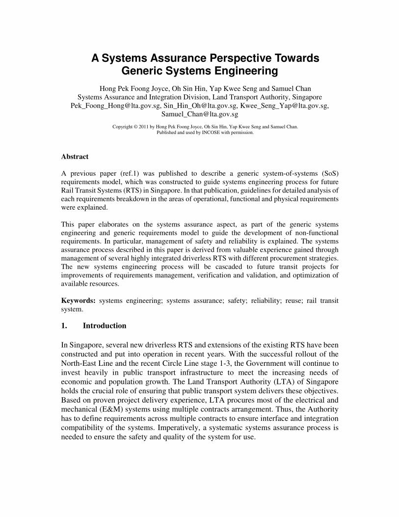
The PSR process is defined by LTA as a mandatory framework for systems assurance
of all RTS projects in Singapore in order to certify that the system is safe for
commencement of passenger services. This safety certification process ensures a staged
based check-and-balance on safety assurance of all RTS projects throughout their
project development lifecycle (see Figure. 1).
The LTA uses IEC 62278 as a general guideline for Reliability, Availability, Maintainability
and Safety (RAMS) management. This standard is also commonly adopted in railway industry
as a comprehensive guide for RAMS assurance activities of a typical railway project lifecycle.
3. Problems and Constraints
The PSR process requires safety targets to be set for each project. In addition, it requires
demonstration that a robust hazard management system has been established. This is
often challenging as we need to have full understanding of the complexity of overall
design and inter-systems relationships. A lack of consistent Systems Engineering (S.E.)
process to support and guide all engineering activities further complicates the matter.
When managing hazards, it is noted that different projects could identify different
hazards when analysing the same system. This could create inconsistencies in system
design and operation. On the other hand, different projects may also recommend and
adopt different hazard mitigation measures for similar hazards. Such inconsistencies
became increasingly challenging for large projects that are constructed in stages e.g.
Circle Line was developed in 5-stages. Inevitably, difference in hazards and mitigations
would increase the risk in human error. For instance, the same operator could
potentially be exposed to the same hazard mitigated using different approaches.
Figure 1 Overview of PSR process
Project
Concept stage
Design stage
Handover stage
Operation stage
(before opening to the
public)
Passenger Service
Concept Safety
Submission (CSS)
Design Safety
Submission (DSS)
Handover Safety
Submission (HSS)
Operation Safety
Submission (OSS)
Audit
Audit
Audit
Audit
Similarly, inconsistencies in system design and operation would create difficulties for
transit regulation.
To accomplish the goals of delivering a successful SoS, an optimum S.E. process is
vital. A new concept for system engineering has been developed and described in detail
in the previous publication (ref.1), this paper will outline the overall concept and
management process and further elaborate the systems assurance approach as part of
the generic systems engineering model.
4. Systems Engineering for Future RTS
We focus on four key areas where systems thinking and valuable experiences are
coalesced to yield the best approach to manage the increasing complexity and
expectations of future RTS projects. They are:
a. A complete systemic elicitation of RTS source requirements from all possible
resources.
b. A generic SoS requirements model to capture all SoS design requirements.
c. Reuse of a generic SoS requirements model for future projects.
d. A learning and adaptable system life cycle with activities that are optimized, cohesive
and continuously refined and reused for future changing needs.
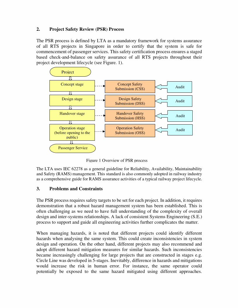
Figure. 2 illustrates this simple yet challenging concept of continuous refinement and reuse in a
driverless RTS operational environment.
5. Generic SOS Requirements Model
Generic SoS requirements model is the fundamental entity for incorporating
requirements elicitation and continuous requirements refinement and reuse. The entire
concept hinges on knowledge preservation and accretion, in full clarity of the
decision-making process and history to reach an agreeable design requirement or
solution. When conscientiously developed, it may enhance the organisation’s capability
to undertake any large-scale SoS challenge and deliver a cost-effective solution in a
Generic SoS
Requirements
Model
Project X
Model
Refinements for future projects
Project Y
Model
Project Z
Model
Driverless RTS
Source
Requirements
Figure. 2 New concept for S.E. implementation
shorter time. Indeed, fulfilling this primary objective has been our greatest goal when
the concept was initially proposed.
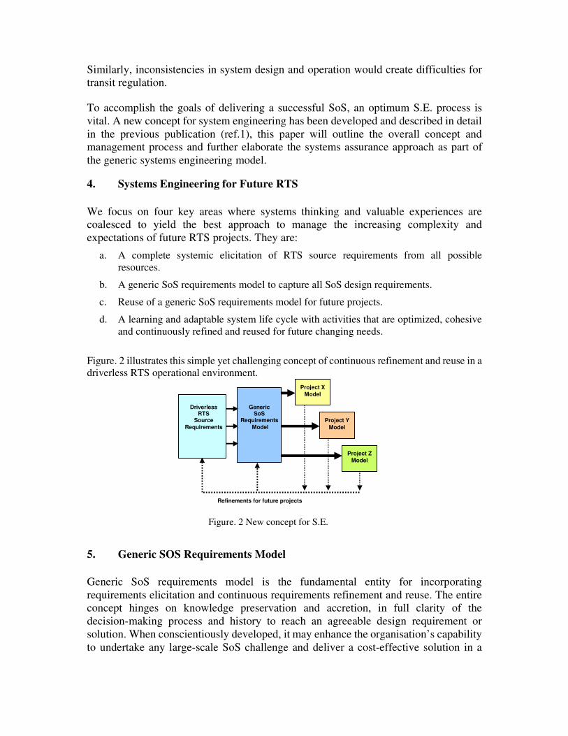
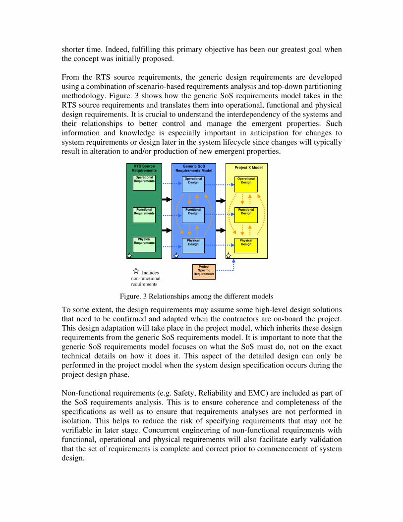
From the RTS source requirements, the generic design requirements are developed
using a combination of scenario-based requirements analysis and top-down partitioning
methodology. Figure. 3 shows how the generic SoS requirements model takes in the
RTS source requirements and translates them into operational, functional and physical
design requirements. It is crucial to understand the interdependency of the systems and
their relationships to better control and manage the emergent properties. Such
information and knowledge is especially important in anticipation for changes to
system requirements or design later in the system lifecycle since changes will typically
result in alteration to and/or production of new emergent properties.
To some extent, the design requirements may assume some high-level design solutions
that need to be confirmed and adapted when the contractors are on-board the project.
This design adaptation will take place in the project model, which inherits these design
requirements from the generic SoS requirements model. It is important to note that the
generic SoS requirements model focuses on what the SoS must do, not on the exact
technical details on how it does it. This aspect of the detailed design can only be
performed in the project model when the system design specification occurs during the
project design phase.
Non-functional requirements (e.g. Safety, Reliability and EMC) are included as part of
the SoS requirements analysis. This is to ensure coherence and completeness of the
specifications as well as to ensure that requirements analyses are not performed in
isolation. This helps to reduce the risk of specifying requirements that may not be
verifiable in later stage. Concurrent engineering of non-functional requirements with
functional, operational and physical requirements will also facilitate early validation
that the set of requirements is complete and correct prior to commencement of system
design.
Generic SoS Requirements Model
Operational Design
Physical Design
Functional Design
Project X Model
Operational Design
Physical Design
Functional Design
Operational Requirements
Functional Requirements
Physical Requirements
RTS Source Requirements
Figure. 3 Relationships among the different models
Project Specific
Requirements Includes
non-functional
requirements
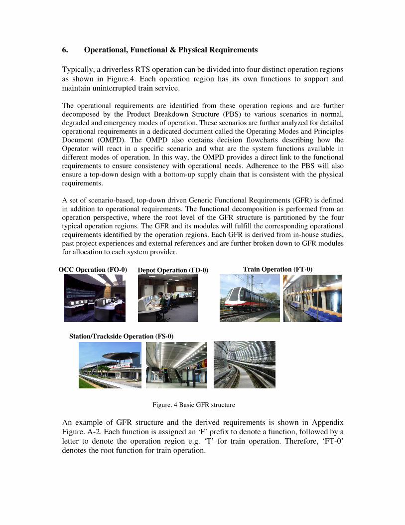
6. Operational, Functional & Physical Requirements
Typically, a driverless RTS operation can be divided into four distinct operation regions
as shown in Figure.4. Each operation region has its own functions to support and
maintain uninterrupted train service.
The operational requirements are identified from these operation regions and are further
decomposed by the Product Breakdown Structure (PBS) to various scenarios in normal,
degraded and emergency modes of operation. These scenarios are further analyzed for detailed
operational requirements in a dedicated document called the Operating Modes and Principles
Document (OMPD). The OMPD also contains decision flowcharts describing how the
Operator will react in a specific scenario and what are the system functions available in
different modes of operation. In this way, the OMPD provides a direct link to the functional
requirements to ensure consistency with operational needs. Adherence to the PBS will also
ensure a top-down design with a bottom-up supply chain that is consistent with the physical
requirements.
A set of scenario-based, top-down driven Generic Functional Requirements (GFR) is defined
in addition to operational requirements. The functional decomposition is performed from an
operation perspective, where the root level of the GFR structure is partitioned by the four
typical operation regions. The GFR and its modules will fulfill the corresponding operational
requirements identified by the operation regions. Each GFR is derived from in-house studies,
past project experiences and external references and are further broken down to GFR modules
for allocation to each system provider.
An example of GFR structure and the derived requirements is shown in Appendix
Figure. A-2. Each function is assigned an ‘F’ prefix to denote a function, followed by a
letter to denote the operation region e.g. ‘T’ for train operation. Therefore, ‘FT-0’
denotes the root function for train operation.
OCC Operation (FO-0) Depot Operation (FD-0)
Station/Trackside Operation (FS-0)
Figure. 4 Basic GFR structure
Train Operation (FT-0)
Concurrently, physical requirements are systematically organized by the PBS, which provides
the whole system breakdown to individual systems and their equipment. The purpose is to
identify all physical requirements and their interfaces with users, environment, technology, etc.
The starting point for the PBS comes from the contract requirements for all systems, which are
in-line with the RTS source requirements. The PBS is used to guide the development of the
system architecture tree, interface matrix and the functional dataflow diagrams. A high-level
representation of a typical RTS system architecture is shown in Appendix Figure. A-1. This
will be further developed into a detailed system architecture document during the design phase
of the project model when the contractors are on-board the project.
The next step is to construct the interface matrix which is used for the identification of interface
relationships among the different systems. Appendix Figure. A-3 shows an example of the
interface matrix which identifies the lead and supporting contractors, so as to facilitate clear
definition the roles and responsibilities during interface design and testing. The lead contractor
is responsible for leading the entire interface design, documentation, off-site and on-site test
activities relating to the interface. The supporting contractor is responsible to provide system
design and support to ensure that these activities are correctly performed.
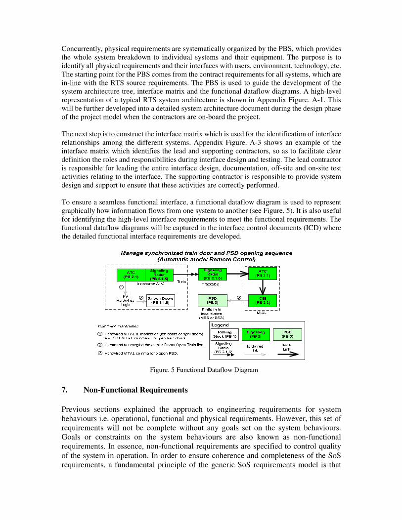
To ensure a seamless functional interface, a functional dataflow diagram is used to represent
graphically how information flows from one system to another (see Figure. 5). It is also useful
for identifying the high-level interface requirements to meet the functional requirements. The
functional dataflow diagrams will be captured in the interface control documents (ICD) where
the detailed functional interface requirements are developed.
7. Non-Functional Requirements
Previous sections explained the approach to engineering requirements for system
behaviours i.e. operational, functional and physical requirements. However, this set of
requirements will not be complete without any goals set on the system behaviours.
Goals or constraints on the system behaviours are also known as non-functional
requirements. In essence, non-functional requirements are specified to control quality
of the system in operation. In order to ensure coherence and completeness of the SoS
requirements, a fundamental principle of the generic SoS requirements model is that
Figure. 5 Functional Dataflow Diagram
non-functional requirements are included in the SoS requirements analysis. This also
prevents the requirements from being derived in isolation, hence easing verification and
validation. As part of project RAMS management, RAMS analysis and safety
requirements management is a continual and iterative process throughout the system
life cycle.
7.1 Safety Requirements Management
One of the key requirements to be validated for system acceptance is that all safety risks of the
system are reduced to a level acceptable by the Safety Authority. Each safety risk is
measureable qualitatively and quantitatively.
Standards such as IEC 62278 are commonly used to guide implementation of control on
qualitative safety risk in the system development lifecycle. In addition, specific industry best
practices such as Railway Safety Principles in UK (also known as the ‘Blue Book’) could also
be applied. With the well-defined guidelines and requirements in applied standards and best
practices, qualitative safety risk can be managed by systematically applying the appropriate
references, as well as regular monitoring and control on the implementation.
Quantitative safety risk, on the other hand is measured based on probabilistic risk assessment
on the system. Hazard analysis is one of the key methods to aid identification of quantitative
safety risks. Consequently, hazard management process needs to be established to facilitate
elimination or reduction of exposed risk in the system so as to ensure that the system can be
accepted for operation. Based on experience, complexity of hazard management increases with
increasing number of interfaces due to procurement strategy and product breakdown. The
potential challenges for hazard management in a highly integrated driverless RTS project
therefore necessitates a more robust hazard management process to ensure allocation of hazard
management responsibilities, while maintaining overall monitoring and control.
The requirements-based hazard management process is introduced as part of the generic S.E.
process and requirements model. One of the key objectives of a requirement-based hazard
management is to formalize the distribution and control of hazard resolutions to the respective
hazard owners. In addition, this process aims to streamline available resources and efforts for
verification and validation (V&V).
As early as the concept phase, potential hazards in the system are identified and analyzed
through various sources (e.g. project experiences, international standards as well as specific
safety studies). Appendix Figure A-5 shows a screen capture of some of the hazards identified
in hazard log. In order to control the number of hazards and efficiency of hazard verification
and validation, each hazard resolution identified, is in turn, used to develop a list of safety
requirements by further reviews and refinements. Typical Requirements Engineering (R.E.)
principles apply to the development of safety requirements, which are subsequently allocated
to the primary actionees, or requirements owners. It is important that newly identified hazards
and hazard resolutions are verified to be unique before adding to the existing project database
to reduce repetition and inconsistency of requirements.
Introduction of requirements-based hazard management aims to minimize ambiguity and
hence improves the usage and effectiveness of resources. Safety requirements are verified to be
correct by tracing to specific system requirements and design. When the system design
specifications are tested, the SoS requirements model ensures that the safety aspect will be
validated as well. This inevitably increases the effectiveness of test as well as provides
evidence for hazard closure in a timely manner.
7.2 Reliability, Availability and Maintainability Requirements
While PBS provides the system breakdown to identify subsystems and equipment, RAM
models are developed to identify every Line Replaceable Units (LRU). Reliability block
diagrams are typical tools used to aid derivation of RAM requirements as well as verification of
design.
From project experience, the elements and properties (e.g. hierarchical position) defined by
RAM models and PBS are not always consistent despite the fact that both are used to describe
the same system. Often, inconsistencies arise and increase following iterative development of
each model in parallel. The problem is further aggravated since development and management
of both models are usually carried out by different teams. While PBS defines the procurement
strategy, RAM model specifies decisions for system acceptance. Undoubtedly, consistency
between both models is important for systems engineering. The Generic SoS Requirements
Model is developed to address this need by defining concurrent development of RAM model
with physical modeling such that the performance requirements are derived and traced using
the same PBS hierarchy. The development approach is further enforced by developing the
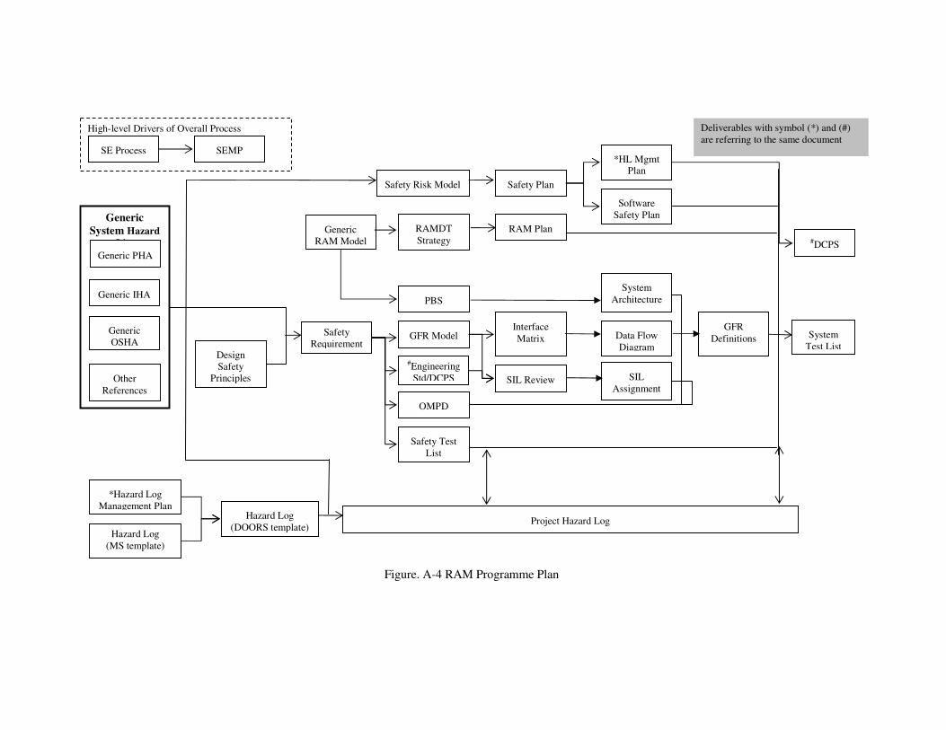
programme plan of RAM activities to execute in parallel with other related systems
engineering activities as shown in Appendix Figure A-4.
This programme plan is developed to address the need that each non-functional
requirement is to be traceable to the implementing function and physical module. This
inherently facilitates verification between RAM model and PBS to ensure their
consistency.
8. Implementation using DOORS
The generic SoS requirements model and project models are stored and managed in-house
using IBM Rational DOORS requirements management tool. This ensures all requirements
defined in the initial stage of the project are explicitly traced and satisfied by the system design.
The system design is then tested and verified to fulfill the RTS source requirements.
Since the generic SoS requirements model serves as a design reference for all future projects, it
must be well documented to capture all the existing and new requirements. To achieve this, the
following documents are maintained in DOORS:
• Design Criteria and Performance Specifications (DCPS).
• Operational concept requirements.
• OMPD.
• Functional requirements (GFR model).
• Functional requirements breakdown and allocation (GFR modules).
• Non-functional requirements (RAMS, EMC etc)
• Functional dataflow diagrams.
• Product breakdown structure.
• System architecture.
• Interface matrix.
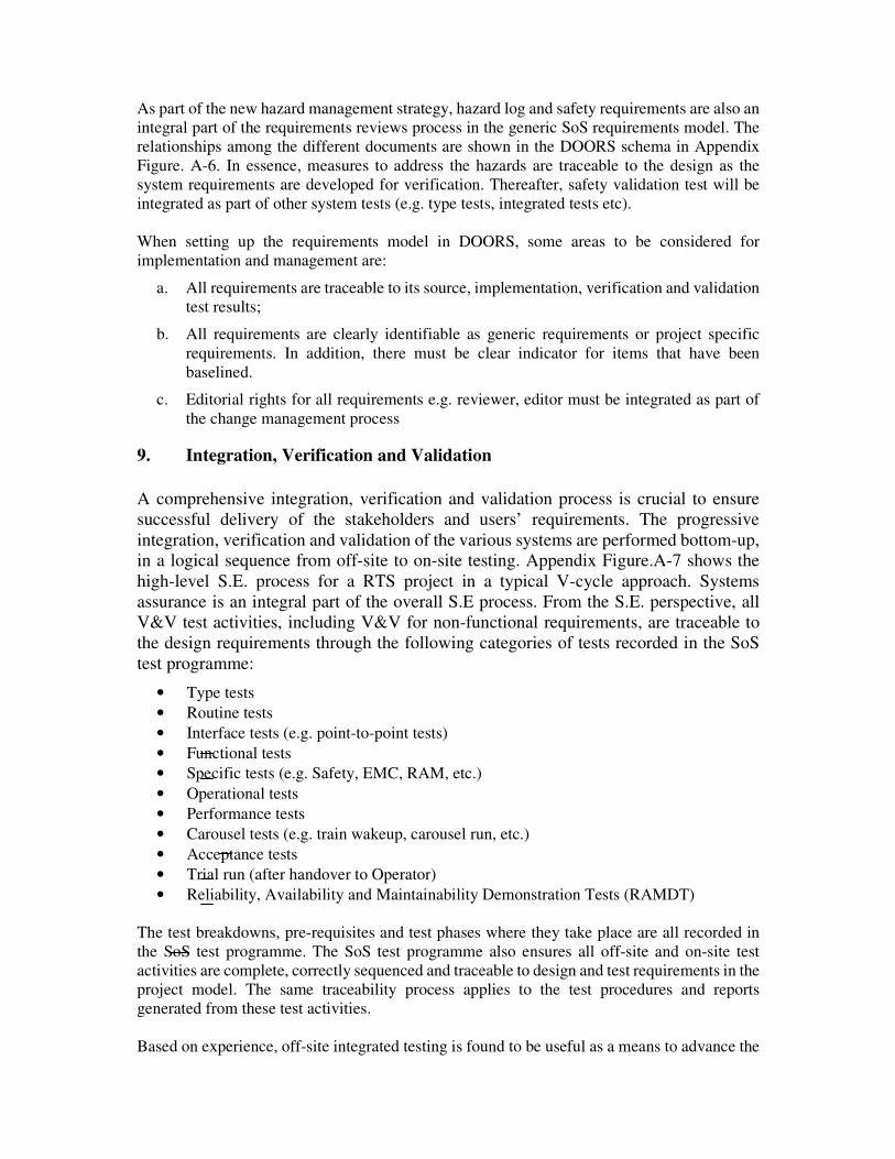
As part of the new hazard management strategy, hazard log and safety requirements are also an
integral part of the requirements reviews process in the generic SoS requirements model. The
relationships among the different documents are shown in the DOORS schema in Appendix
Figure. A-6. In essence, measures to address the hazards are traceable to the design as the
system requirements are developed for verification. Thereafter, safety validation test will be
integrated as part of other system tests (e.g. type tests, integrated tests etc).
When setting up the requirements model in DOORS, some areas to be considered for
implementation and management are:
a. All requirements are traceable to its source, implementation, verification and validation
test results;
b. All requirements are clearly identifiable as generic requirements or project specific
requirements. In addition, there must be clear indicator for items that have been
baselined.
c. Editorial rights for all requirements e.g. reviewer, editor must be integrated as part of
the change management process
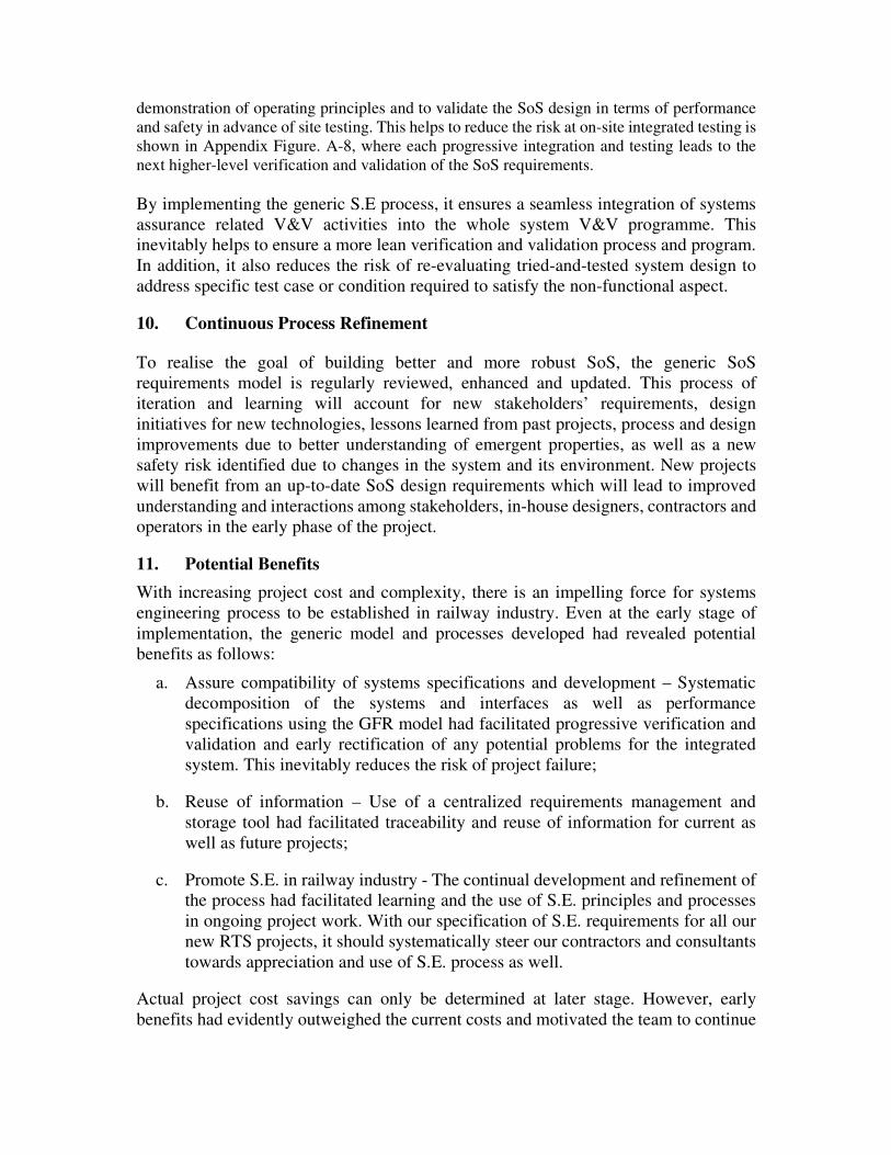
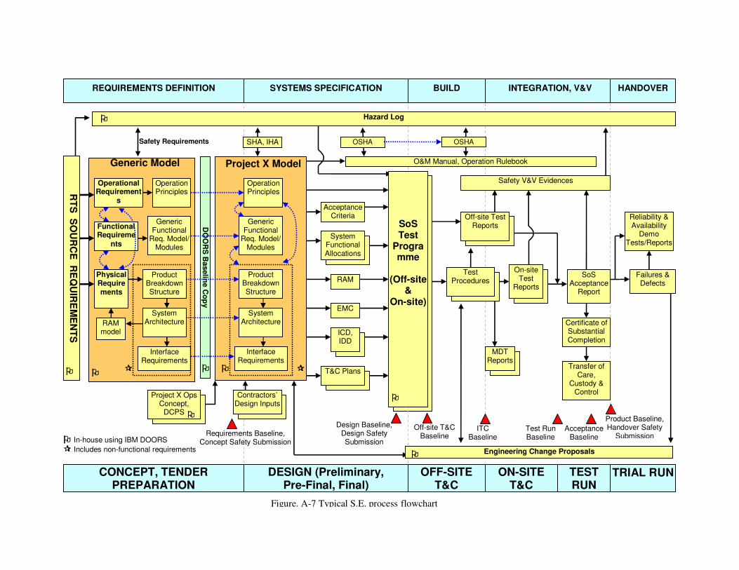
9. Integration, Verification and Validation
A comprehensive integration, verification and validation process is crucial to ensure
successful delivery of the stakeholders and users’ requirements. The progressive
integration, verification and validation of the various systems are performed bottom-up,
in a logical sequence from off-site to on-site testing. Appendix Figure.A-7 shows the
high-level S.E. process for a RTS project in a typical V-cycle approach. Systems
assurance is an integral part of the overall S.E process. From the S.E. perspective, all
V&V test activities, including V&V for non-functional requirements, are traceable to
the design requirements through the following categories of tests recorded in the SoS
test programme:
• Type tests
• Routine tests
• Interface tests (e.g. point-to-point tests)
• Functional tests
• Specific tests (e.g. Safety, EMC, RAM, etc.)
• Operational tests
• Performance tests
• Carousel tests (e.g. train wakeup, carousel run, etc.)
• Acceptance tests
• Trial run (after handover to Operator)
• Reliability, Availability and Maintainability Demonstration Tests (RAMDT)
The test breakdowns, pre-requisites and test phases where they take place are all recorded in
the SoS test programme. The SoS test programme also ensures all off-site and on-site test
activities are complete, correctly sequenced and traceable to design and test requirements in the
project model. The same traceability process applies to the test procedures and reports
generated from these test activities.
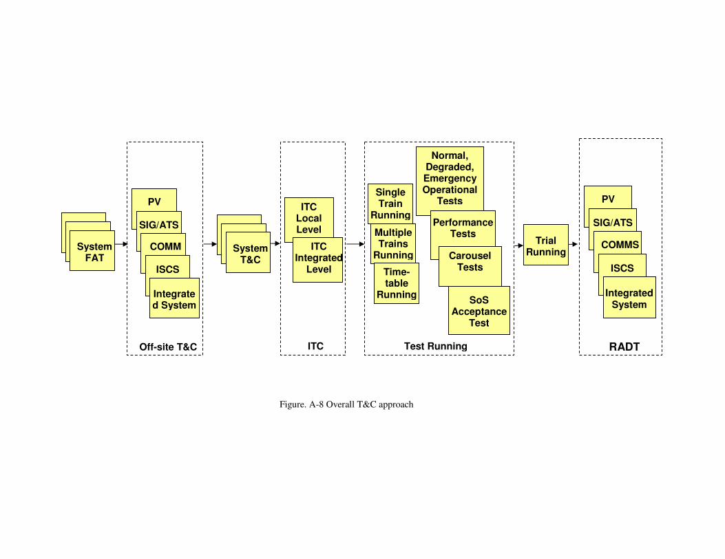
Based on experience, off-site integrated testing is found to be useful as a means to advance the
demonstration of operating principles and to validate the SoS design in terms of performance
and safety in advance of site testing. This helps to reduce the risk at on-site integrated testing is
shown in Appendix Figure. A-8, where each progressive integration and testing leads to the
next higher-level verification and validation of the SoS requirements.
By implementing the generic S.E process, it ensures a seamless integration of systems
assurance related V&V activities into the whole system V&V programme. This
inevitably helps to ensure a more lean verification and validation process and program.
In addition, it also reduces the risk of re-evaluating tried-and-tested system design to
address specific test case or condition required to satisfy the non-functional aspect.
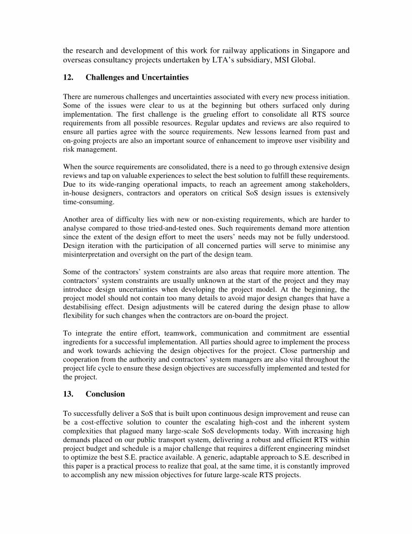
10. Continuous Process Refinement
To realise the goal of building better and more robust SoS, the generic SoS
requirements model is regularly reviewed, enhanced and updated. This process of
iteration and learning will account for new stakeholders’ requirements, design
initiatives for new technologies, lessons learned from past projects, process and design
improvements due to better understanding of emergent properties, as well as a new
safety risk identified due to changes in the system and its environment. New projects
will benefit from an up-to-date SoS design requirements which will lead to improved
understanding and interactions among stakeholders, in-house designers, contractors and
operators in the early phase of the project.
11. Potential Benefits
With increasing project cost and complexity, there is an impelling force for systems
engineering process to be established in railway industry. Even at the early stage of
implementation, the generic model and processes developed had revealed potential
benefits as follows:
a. Assure compatibility of systems specifications and development – Systematic
decomposition of the systems and interfaces as well as performance
specifications using the GFR model had facilitated progressive verification and
validation and early rectification of any potential problems for the integrated
system. This inevitably reduces the risk of project failure;
b. Reuse of information – Use of a centralized requirements management and
storage tool had facilitated traceability and reuse of information for current as
well as future projects;
c. Promote S.E. in railway industry - The continual development and refinement of
the process had facilitated learning and the use of S.E. principles and processes
in ongoing project work. With our specification of S.E. requirements for all our
new RTS projects, it should systematically steer our contractors and consultants
towards appreciation and use of S.E. process as well.
Actual project cost savings can only be determined at later stage. However, early
benefits had evidently outweighed the current costs and motivated the team to continue
the research and development of this work for railway applications in Singapore and
overseas consultancy projects undertaken by LTA’s subsidiary, MSI Global.
12. Challenges and Uncertainties
There are numerous challenges and uncertainties associated with every new process initiation.
Some of the issues were clear to us at the beginning but others surfaced only during
implementation. The first challenge is the grueling effort to consolidate all RTS source
requirements from all possible resources. Regular updates and reviews are also required to
ensure all parties agree with the source requirements. New lessons learned from past and
on-going projects are also an important source of enhancement to improve user visibility and
risk management.
When the source requirements are consolidated, there is a need to go through extensive design
reviews and tap on valuable experiences to select the best solution to fulfill these requirements.
Due to its wide-ranging operational impacts, to reach an agreement among stakeholders,
in-house designers, contractors and operators on critical SoS design issues is extensively
time-consuming.
Another area of difficulty lies with new or non-existing requirements, which are harder to
analyse compared to those tried-and-tested ones. Such requirements demand more attention
since the extent of the design effort to meet the users’ needs may not be fully understood.
Design iteration with the participation of all concerned parties will serve to minimise any
misinterpretation and oversight on the part of the design team.
Some of the contractors’ system constraints are also areas that require more attention. The
contractors’ system constraints are usually unknown at the start of the project and they may
introduce design uncertainties when developing the project model. At the beginning, the
project model should not contain too many details to avoid major design changes that have a
destabilising effect. Design adjustments will be catered during the design phase to allow
flexibility for such changes when the contractors are on-board the project.
To integrate the entire effort, teamwork, communication and commitment are essential
ingredients for a successful implementation. All parties should agree to implement the process
and work towards achieving the design objectives for the project. Close partnership and
cooperation from the authority and contractors’ system managers are also vital throughout the
project life cycle to ensure these design objectives are successfully implemented and tested for
the project.
13. Conclusion
To successfully deliver a SoS that is built upon continuous design improvement and reuse can
be a cost-effective solution to counter the escalating high-cost and the inherent system
complexities that plagued many large-scale SoS developments today. With increasing high
demands placed on our public transport system, delivering a robust and efficient RTS within
project budget and schedule is a major challenge that requires a different engineering mindset
to optimize the best S.E. practice available. A generic, adaptable approach to S.E. described in
this paper is a practical process to realize that goal, at the same time, it is constantly improved
to accomplish any new mission objectives for future large-scale RTS projects.

APPENDIX
TIMS
(PB 1.3.9)
ATC(PB 2.1)
Rolling Stock
(PB 1)
Comms (PB 4)
(ICP, VSS, Radio,
DVR)
Signalling
(PB 2)
Track Work/ 3rd
Rail (PB 10)
(Mainline)
TVS
(PB 13.1.1 )
Comms
(PB 4)
FPS
(PB 14.1)Trackside
Train borne
Signalling
(PB 2)
ISCS
(PB 5)
AFC (PB 9)
Lifts and
Escalators
(PB 12.1)
FPS
(PB 14.1)
AMS (PB 8)
MMS (PB 7)
HV/TP
(PB 6)
LV (PB 15.1)
Comms
(PB 4)
ECS
(PB 13.1.2)
To ATS in
adjacent MSS /
Depot /OCC
Station
CBN
(PB 4.1)
OCC Depot
MMS (PB 7) MMS (PB 7)
AMS (PB 8)AMS (PB 8)
Comms
(PB 4)
Comms
(PB 4)
ISCS
(PB 5)ISCS
(PB 5)
Signalling
(PB 2) Signalling
(PB 2)
DE (PB 16)
Lifts
(PB 12.2)
FPS
(PB 14.2)
ECS
(PB 13.2)
LV (PB 15.2)
HV/TP
(PB 6)
Track Work/
3rd Rail
(PB 10)
(Depot)
RTS System Architecture
2
2
AFC (PB 9)
BMS (PB 17)
PSD
(PB 3)
5
5
5
5
5
SIG CBN
(PB 2.2.5.1)
NOTE These two interfaces are not shown in the diagram:
1. LV to provide power for all station and depot equipment if required.
2. LV to provide UPS for SIG, ISCS, MMS, Comms, AMS, TV-ECS, FPS.
From ATS
(in MSS) to
ISCS (in SSS in the
same ATC
sector)
5
Rolling
Stock (PB 1)
Signalling
(PB 2)
PSD (PB 3)
Comms
(PB 4)
ISCS
(PB 5)
HV/TP
(PB 6)
MMS (PB 7)
AMS (PB 8)
AFC (PB 9)
Track Work/
3rd Rail
(PB 10)
Lifts and
Escalators
(PB 12)
TV-ECS
(PB 13)
FPS (PB 14)
LV (PB 15)
DE (PB 16)
BMS (PB 17)
2 Link to clock
Link to ISCS5
Legend
Figure. A-1 RTS system architecture
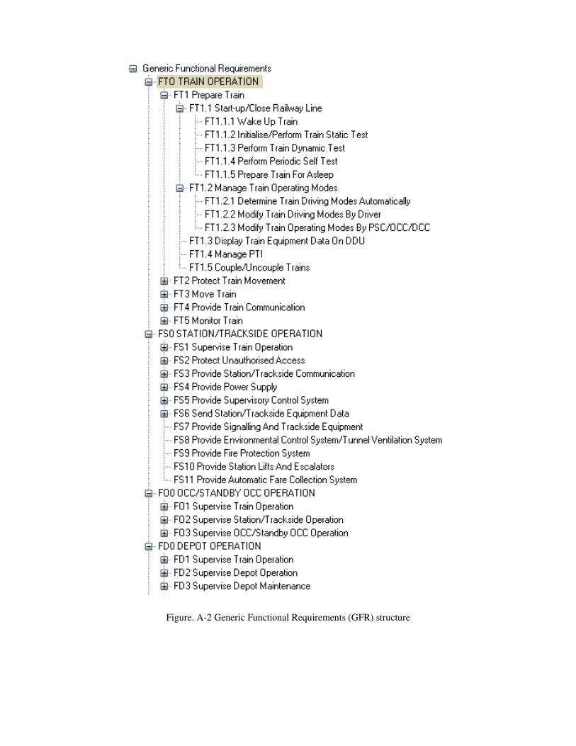
Figure. A-2 Generic Functional Requirements (GFR) structure
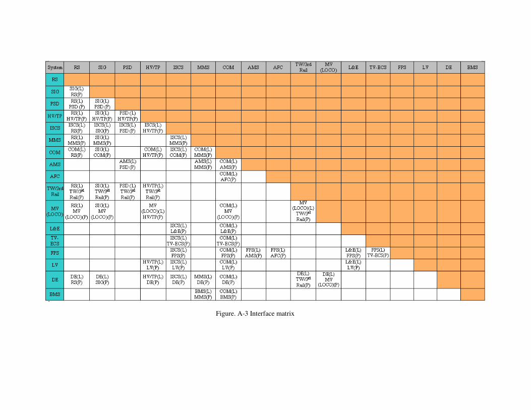
Figure. A-3 Interface matrix
Project Hazard Log
#DCPS
High-level Drivers of Overall Process
Generic
System Hazard
List
System
Test List
Generic PHA
Generic IHA
Generic
OSHA
Other
References
*Hazard Log
Management Plan
Design
Safety
Principles
Generic
RAM Model
Safety
Requirement
Hazard Log
(DOORS template)
Safety Risk Model
RAMDT
Strategy
PBS
GFR Model
#Engineering
Std/DCPS
OMPD
Safety Test
List
Safety Plan
RAM Plan
Interface
Matrix
SIL Review
*HL Mgmt
Plan
Software
Safety Plan
System
Architecture
Data Flow
Diagram
SIL
Assignment
Hazard Log
(MS template)
GFR
Definitions
SE Process SEMP
Deliverables with symbol (*) and (#)
are referring to the same document
Figure. A-4 RAM Programme Plan
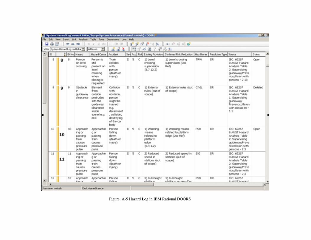
Figure. A-5 Hazard Log in IBM Rational DOORS
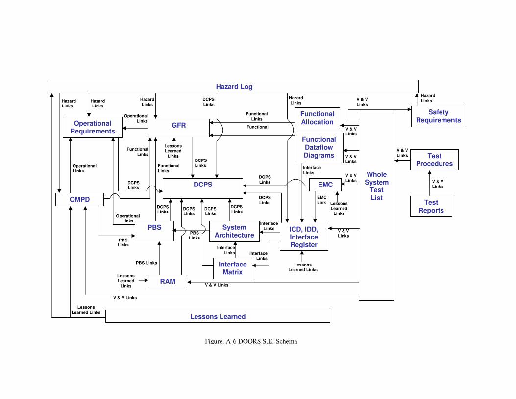
Figure. A-6 DOORS S.E. Schema
Hazard Log
Operational Requirements
GFR
PBS
OMPD
Functional Allocation
System Architecture
RAM
ICD, IDD, Interface Register
Interface Matrix
EMC
Functional Dataflow Diagrams
Whole System
Test List
Safety Requirements
Test Procedures
Test Reports
Operational Links
Operational Links
Functional Links
Functional Links
PBS Links
Hazard Links
Hazard Links
Interface Links
Interface Links
PBS Links
Functional Links
Hazard Links
Hazard Links
Hazard Links
V & V Links V & V Links
V & V Links
V & V Links
V & V Links
V & V Links
V & V Links
V & V Links
V & V Links
EMC Link
Interface Links
Operational Links
Functional Links
DCPS Links DCPS
Links
DCPS Links
DCPS Links
PBS Links
Interface Links
DCPS
Lessons Learned
Links
Lessons Learned Links
DCPS Links
DCPS Links
DCPS Links
Lessons Learned
Links
Lessons Learned Lessons
Learned Links
DCPS Links
Lessons Learned
Links
DCPS Links
����
On-site
Test Reports
Certificate of Substantial Completion
CONCEPT, TENDER PREPARATION
DESIGN (Preliminary, Pre-Final, Final)
OFF-SITE T&C
ON-SITE T&C
TEST RUN
TRIAL RUN
Failures & Defects
Test Run Baseline
Design Baseline, Design Safety Submission
Product Baseline, Handover Safety
Submission
MDT
Reports
O&M Manual, Operation Rulebook
OSHA OSHA
Contractors’
Design Inputs
EMC
REQUIREMENTS DEFINITION SYSTEMS SPECIFICATION INTEGRATION, V&V HANDOVER BUILD
Transfer of Care,
Custody & Control
SoS Acceptance
Report
Reliability & Availability
Demo Tests/Reports
Safety Requirements
Off-site Test
Reports
Requirements Baseline, Concept Safety Submission
ICD, IDD
ITC Baseline
Operational Requirement
s
Physical Requirements
Generic Model
Operation Principles
Generic Functional
Req. Model/ Modules
Project X Model
Operation Principles
Generic Functional
Req. Model/ Modules
����
SoS Test
Programme
(Off-site
& On-site)
����
*
System
Functional Allocations
Acceptance Criteria
T&C Plans
RAM
DO
OR
S B
aselin
e C
op
y
����
Functional Requireme
nts
Safety V&V Evidences
Interface Requirements
Product Breakdown Structure
System Architecture
Test
Procedures
Project X Ops
Concept, DCPS
Acceptance Baseline
RT
S S
OU
RC
E R
EQ
UIR
EM
EN
TS
����
���� In-house using IBM DOORS
���� Includes non-functional requirements
Figure. A-7 Typical S.E. process flowchart
SHA, IHA
Off-site T&C Baseline
Engineering Change Proposals ����
���� ����
����
Hazard Log ����
RAM model
System Architecture
Interface Requirements
Product Breakdown Structure
System FAT
PV
SIG/ATS
COMM
ISCS
Integrated System
Off-site T&C
ITC Local Level
ITC Integrated
Level
ITC Test Running
Normal, Degraded, Emergency Operational
Tests
Performance Tests
Trial Running
Single Train
Running
Multiple Trains
Running
Time- table
Running
Carousel Tests
SoS Acceptance
Test
System T&C
Figure. A-8 Overall T&C approach
RADT
PV
SIG/ATS
COMMS
ISCS
Integrated System
References
1. Oh Sin Hin, Hong P F Joyce, Samuel Chan, A Practical Approach to implementing Generic
Systems Engineering, World Urban Transit Conference 2010
2. Khoo Shee Kang, Tang Chin Nang, Safety Certification Process for Rapid Transit Systems
in Singapore, Asia Pacific Conference on Risk Management & Safety, Kowloon, Hong
Kong 2005
3. IEC 62278 Ed.1:Railway applications - Specification and demonstration of reliability,
availability, maintainability and safety (RAMS), International Electrotechnical Committee
4. IEC 62290-2 Ed. 1: Railway Applications – Urban Guided Transport Management and
Command/Control Systems – Part 2: Functional Requirements Specification
5. Sim Wee Meng, Samuel Chan, Ken Ng K.S., Systems Integration Process on NEL, RTS
Conference Singapore 2003.
6. Leong Kwok Weng, Samuel Chan, Oh Sin Hin, Experiences on Systems Integration
Management of Rail Transit Projects, Singapore Systems Engineering Conference 2007.
7. Oh Sin Hin, Samuel Chan, Generic Functional Model for Driverless Rail Transit Systems,
INCOSE Conference Hong Kong 2008.