a systematic modeling framework of superstructure...
TRANSCRIPT

Computers and Chemical Engineering 23 (1999) 709–731
A systematic modeling framework of superstructure optimizationin process synthesis
Hector Yeomans, Ignacio E. Grossmann *Department of Chemical Engineering, Carnegie Mellon Uni6ersity, Pittsburgh PA 15213, USA
Received 22 December 1998; accepted 22 December 1998
Abstract
A systematic framework is presented for the representation of superstructures and derivation of optimization models in processsynthesis. The state task network (STN) and state equipment network (SEN) are proposed as the two fundamental representationsof superstructures for process systems involving mass, heat and momentum transfer. The mathematical modeling of either of thetwo representations is performed with generalized disjunctive programming (GDP), and then converted systematically into mixedinteger linear programs/mixed integer non-linear programs (MILP/MINLP) problems. The application of this methodology isillustrated with the synthesis of distillation sequences, with and without heat integration, which lead to MILP problems. It isshown that ad hoc models that have been reported in the literature can be systematically derived, and in the case of separationsequences with heat integration, a new improved model is derived. Numerical results for comparing alternative models are alsopresented. © 1999 Elsevier Science Ltd. All rights reserved.
1. Introduction
In process synthesis, there are two major approachesthat a design engineer can take to determine the opti-mal configuration of a flowsheet and its operatingconditions. In one approach the problem can be solvedin sequential form, by decomposition, fixing some ele-ments in the flowsheet, and then using heuristic rules todetermine changes in the flowsheet that may lead to animproved solution. An example of such an approach isthe sequential hierarchical decomposition strategy byDouglas (1988). While this procedure is relatively sim-ple to implement, the sequential nature of the decisionsand the heuristic rules that are used can lead to sub-op-timal designs.
The second strategy that can be applied to solve aprocess synthesis problem is based on simultaneousoptimization using mathematical programming (Gross-mann, 1996). This strategy requires to postulate a su-perstructure that includes equipment that can bepotentially selected in the final flowsheet, as well astheir interconnection. The equations of the equipment
and their connectivity, and constraints for the operatingconditions are then incorporated in an optimizationproblem where an objective function is specified such ascost minimization or profit maximization. This ap-proach generally requires the use of discrete variables torepresent the choices of equipment, with which themodel becomes a mixed integer linear or non-linearprogram (MILP or MINLP). The advantage of mathe-matical programming strategies for process synthesis isthat they perform simultaneous optimization of theconfiguration and operating conditions. The drawbackis that global optimality conditions cannot be guaran-teed for nonlinear models unless specific methods forglobal optimization are used.
Most of the work that has been reported with themathematical programming approach for process syn-thesis has concentrated in developing ad hoc models forspecific types of problems. For instance, Yee andGrossmann (1990) and Ciric and Floudas (1991) haveproposed specialized superstructure representations andMINLP models for heat exchanger networks. Gamini-bandara and Sargent (1976), Andrecovich and Wester-berg (1985), and Aggrawal and Floudas (1990), haveproposed a number of models for selecting distillationsequences. Andrecovich and Westerberg (1985), Flou-
* Corresponding author.E-mail address: [email protected] (I.E. Grossmann)
0098-1354/99/$ - see front matter © 1999 Elsevier Science Ltd. All rights reserved.
PII: S 0 0 9 8 -1354 (99 )00003 -4

H. Yeomans, I.E. Grossmann / Computers and Chemical Engineering 23 (1999) 709–731710
das and Paules (1988), and Raman and Grossmann(1994), have developed superstructures for heat-inte-grated distillation sequences with sharp separations.Sargent (1998) has developed a state-task network(STN) representation for the synthesis of non-idealdistillation sequences. Balakrishna and Biegler (1992)and Kokossis and Floudas (1991) have proposed super-structure representations for reactor networks.
As for mathematical modeling techniques for super-structures, Kocis and Grossmann (1989) proposed aMINLP modeling decomposition strategy in which theflowsheet is partitioned into process units and intercon-nection nodes, and where the NLP sub-problems onlyinvolve existing units. Non-existing units are sub-opti-mized with a Lagrangian decomposition to set up theinitial MILP master problem. Bagajewicz and Manou-siothakis (1992) proposed a ‘state space’ representation,by decomposing the flowsheet into a block for thedistribution network and blocks for different operators,in which design equations for the equipment tasks areincluded. The operators are typically solved using pinchanalysis models for heat and mass exchanger networks.Papalexandri and Pistikopoulos (1996) proposed amodeling strategy where they disaggregate the flowsheetelements into two types of building blocks: a heat andmass exchange block and pure heat exchanger block.Operations such as distillation, reaction, absorptionand other unit operations are then represented withthese building blocks. Recently, Smith (1996) intro-duced the ‘state operator network’, where he considersfull connectivity among all the potential equipment in aflowsheet for which no tasks are pre-assigned, sincerigorous models are used. The combinatorics are re-duced to selecting the equipment. This strategy, how-ever, can have significant convergence difficulties due tothe non-convexities that are introduced in the intercon-nection equations (e.g. bilinear equations). The work ofKocis and Grossmann (1989), Bagajewicz and Manou-siothakis (1992), Papalexandri and Pistikopoulos (1996)and Smith (1996) has shown the great importance ofrepresentation and modeling in the optimization offlowsheet superstructures.
The goal of this paper is to develop a general repre-sentation and modeling framework for systematicallyderiving process synthesis models. The state task net-work (STN) and state equipment network (SEN),which are complementary to each other, will be pro-posed as two basic problem representations for processsynthesis. These representations will be modeledthrough generalized disjunctive programming (GDP)(Raman & Grossmann, 1994) from which specificmixed-integer optimization models can be derived. Therepresentation and modeling of synthesis problems,which will be restricted to linear process models, will beillustrated with sharp distillation synthesis problemswith and without heat integration. Numerical examples
will be presented to demonstrate the advantages of theproposed representation and modeling strategies.
2. Problem statement
The problem addressed in this paper can be stated asfollows: given is a set of equipment, raw materials,products and process alternatives in terms of differentchoices of tasks and equipment, and the interconnec-tions among them. The objective is to establish a sys-tematic procedure for representing these elements in asuperstructure, and for deriving a mathematical pro-gramming model with discrete and continuous variablesto predict an optimum flowsheet design.
Since this paper is a first step for developing asystematic and comprehensive framework for derivingoptimization synthesis models, we will restrict the treat-ment to problems with linear process models. Further-more, only flows of material and heat will beconsidered.
3. General elements of flowsheets
Flowsheets are generally regarded as a network com-posed of streams and equipment. However, a moregeneral characterization requires three basic elements:states, tasks and equipment.� States are defined as the set of physical and chemical
properties that identify a stream in the process. Thedefinition of a state includes quantitative intensiveand extensive properties of a stream, such as compo-sition, temperature, pressure, particle size, heat con-tent, mass flow, etc. However, this quantitativeinformation is limited, and therefore it is necessaryto include also qualitative information (Papalexandri& Pistikopoulos 1996). The qualitative propertiesthat can be used to characterize a state are the nameof the components that can be present, or will beallowed to be present in the streams, and thephase(s) of the stream. Also, other labels may berequired such as a heat exchange label (hot stream,cold stream, stream to be condensed or vaporized), amass transfer label (rich or lean stream, solvent,solute, absorbent, absorbate) and a momentumtransfer label (turbulent or laminar flow, stagnantfluid, fluidized phase). It should be noticed that ingeneral a state corresponds to a process stream,unless the level of detail describing the states is suchthat several streams can be associated to a singlestate.
� Tasks can be defined as the physical and chemicaltransformations that occur between adjacent states.The tasks will correspond to momentum, mass, andenergy transfer operations (e.g. distillation, absorp-
H. Yeomans, I.E. Grossmann / Computers and Chemical Engineering 23 (1999) 709–731 711
tion, reaction, membrane separation, mixing) whichare described by conservation, equilibrium and rateequations.
� Equipment are the elements of a flowsheet corre-sponding to the physical devices that will execute agiven task (e.g. reactor, absorber, heat exchanger).The equipment parameters are determined from thecorresponding design equations.
4. General framework for process synthesis
The general framework proposed in this paper iscomposed of three major steps that will be described indetail in this section. These steps are rather general, andcan in principle be applied to any synthesis problem toderive a mathematical programming model for predict-ing an optimal flowsheet configuration.
In the initial step of the proposed framework we willfirst consider two major superstructure representations:the STN, in which the tasks and states are defined whilethe equipment assignment is generally unknown, andthe SEN in which the tasks and the equipment aredefined while the assignment of tasks to equipmentmust be determined. Based on these network represen-tations, we will model the corresponding synthesisproblems with GDP (Raman & Grossmann, 1994;
Turkay & Grossmann, 1996a). These logic based meth-ods will then be used as basis for deriving algebraicmixed-integer optimization models.
4.1. State task network (STN) representation
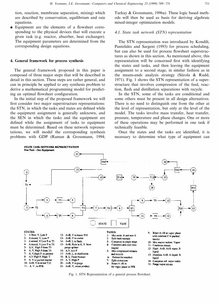
The STN representation was introduced by Kondili,Pantelides and Sargent (1993) for process scheduling,but can also be used for process flowsheet superstruc-tures as shown in this section. As mentioned above, thisrepresentation will be concerned first with identifyingthe states and tasks, and then leaving the equipmentassignment to a second stage, in similar fashion as inthe means-ends analysis strategy (Siirola & Rudd,1971). Fig. 1 shows the STN representation of a super-structure that involves compression of the feed, reac-tion, flash and distillation separations with recycle.
In the STN, some of the tasks are conditional andsome others must be present in all design alternatives.There is no need to distinguish one from the other atthe level of representation, but only at the level of themodel. The tasks involve mass transfer, heat transfer,pressure, temperature and phase changes. One or moreof these operations may be performed in one task iftechnically feasible.
Once the states and the tasks are identified, it isnecessary to determine what type of equipment can
Fig. 1. STN Representation of a general process flowsheet.
H. Yeomans, I.E. Grossmann / Computers and Chemical Engineering 23 (1999) 709–731712
Fig. 2. One task–one equipment (OTOE) assignment for the STN representation.
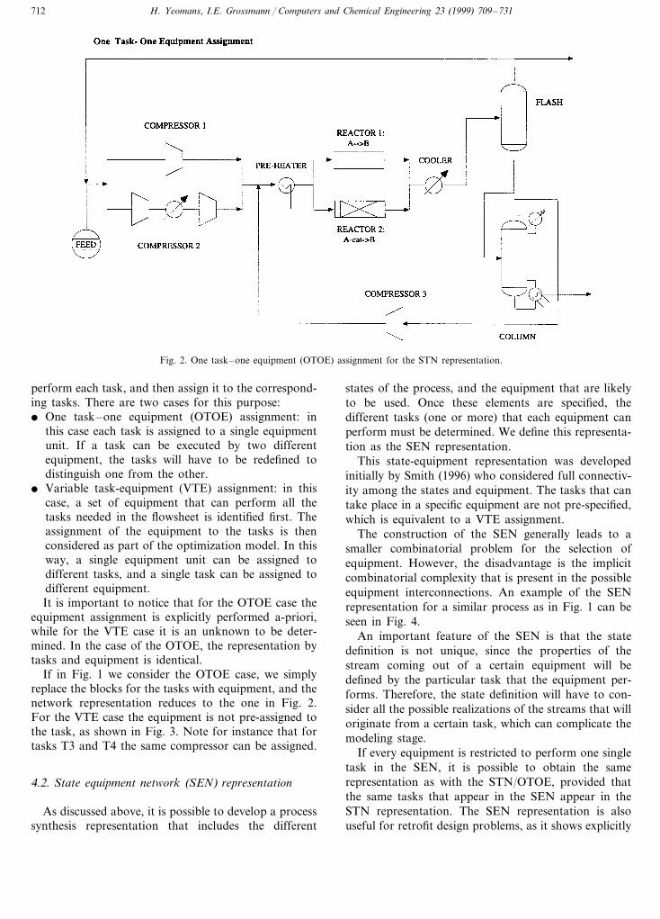
perform each task, and then assign it to the correspond-ing tasks. There are two cases for this purpose:� One task–one equipment (OTOE) assignment: in
this case each task is assigned to a single equipmentunit. If a task can be executed by two differentequipment, the tasks will have to be redefined todistinguish one from the other.
� Variable task-equipment (VTE) assignment: in thiscase, a set of equipment that can perform all thetasks needed in the flowsheet is identified first. Theassignment of the equipment to the tasks is thenconsidered as part of the optimization model. In thisway, a single equipment unit can be assigned todifferent tasks, and a single task can be assigned todifferent equipment.It is important to notice that for the OTOE case the
equipment assignment is explicitly performed a-priori,while for the VTE case it is an unknown to be deter-mined. In the case of the OTOE, the representation bytasks and equipment is identical.
If in Fig. 1 we consider the OTOE case, we simplyreplace the blocks for the tasks with equipment, and thenetwork representation reduces to the one in Fig. 2.For the VTE case the equipment is not pre-assigned tothe task, as shown in Fig. 3. Note for instance that fortasks T3 and T4 the same compressor can be assigned.
4.2. State equipment network (SEN) representation
As discussed above, it is possible to develop a processsynthesis representation that includes the different
states of the process, and the equipment that are likelyto be used. Once these elements are specified, thedifferent tasks (one or more) that each equipment canperform must be determined. We define this representa-tion as the SEN representation.
This state-equipment representation was developedinitially by Smith (1996) who considered full connectiv-ity among the states and equipment. The tasks that cantake place in a specific equipment are not pre-specified,which is equivalent to a VTE assignment.
The construction of the SEN generally leads to asmaller combinatorial problem for the selection ofequipment. However, the disadvantage is the implicitcombinatorial complexity that is present in the possibleequipment interconnections. An example of the SENrepresentation for a similar process as in Fig. 1 can beseen in Fig. 4.
An important feature of the SEN is that the statedefinition is not unique, since the properties of thestream coming out of a certain equipment will bedefined by the particular task that the equipment per-forms. Therefore, the state definition will have to con-sider all the possible realizations of the streams that willoriginate from a certain task, which can complicate themodeling stage.
If every equipment is restricted to perform one singletask in the SEN, it is possible to obtain the samerepresentation as with the STN/OTOE, provided thatthe same tasks that appear in the SEN appear in theSTN representation. The SEN representation is alsouseful for retrofit design problems, as it shows explicitly

H. Yeomans, I.E. Grossmann / Computers and Chemical Engineering 23 (1999) 709–731 713
the existing equipment of the given problem. Finally,one can also often determine ahead of time the numberof equipment that is needed, in which case the opti-mization reduces to assigning the tasks and determiningthe interconnections of the equipment.
4.3. Generalized disjuncti6e programming (GDP)modeling
The second step of the proposed framework forprocess synthesis corresponds to the modeling of thechosen representation, STN or SEN, as a mathematicalprogramming problem. Since there will be conditionaltasks or equipment that might be selected or not in thefinal flowsheet, it is necessary to use a discrete mathe-matical programming model. The use of disjunctiveprogramming (Balas, 1979) is of particular interest,since process synthesis problems naturally lead to mod-els where the solution space is disjoint, and there is astrong logic on the connectivity among the differenttasks (Raman & Grossmann 1993, 1994).
In order to use GDP (Raman & Grossmann, 1994) tomodel the STN or SEN representations, it is necessaryto identify the conditional constraints from amongthose that must hold for all synthesis alternatives. Theconditional constraints will be represented with disjunc-tions and assigned a Boolean variable that represents itsexistence (if the Boolean variable takes a value of‘true’). In general mixers and splitters can be consideredconditional tasks. However, if the equations that areapplied to the mixer and splitter are only mass andenergy balances, these constraints do not involve anytype of discrete decision or discrete variable assignmentfor them to be valid. For this reason they are consid-ered permanent in this paper.
4.4. GDP models for STN representation
In order to formulate the GDP model, the followingsets and variables must be defined. Let t�T define theset of tasks in the superstructure, where T=TP@TC
and TP is the set of permanent tasks (valid for all designalternatives) and TC is the set of conditional tasks thatmay be selected. Let s�S define the set of states, andj�E define the set of equipment units. Let It={s � s isan input state of task t}, and Ot={s %� s % is an outputstate of task t}. The variables zt, xs and dj are used torepresent the operating variables in the tasks, the flowand state variables interconnecting the states, and thedesign variables for the equipment, respectively. Thefunction ht(zt, xs, xs%) represents the equations (massbalances, energy balances, etc.) and constraints corre-sponding to task t, and rj(dj, xs, xs%, zt) represents theequations and constraints corresponding to a particularequipment design. Finally, f(dj, zt) represents the costfunction in terms of the design and control variables, dj
and zt.If the OTOE case is considered for the STN super-
structure, the equations and constraints from equip-ment and tasks can be integrated in the vectorgt= [ht(zt, xs, xs%), rj %(dj %, xs, xs%, zt)]T where j %�Qt={ j %�E � j % is associated with task t}, and � t�TQt=¥.The GDP model for STN/OTOE representation is thenas follows,
(P-STN1): min %t�T
ct+ %s�S
asxs (1)
s.t. gt(dj %, zt, xs, xs%)50ct= f(dj %, zt)
" j %�Qt% t�TP
s�I t, s %�Ot
(2)
Fig. 3. VTE assignment for the STN representation.

H. Yeomans, I.E. Grossmann / Computers and Chemical Engineering 23 (1999) 709–731714
Fig. 4. SEN representation of a synthesis problem.
V(y)=True (4)
d�D, z�Z, x�X Yt={True, False}
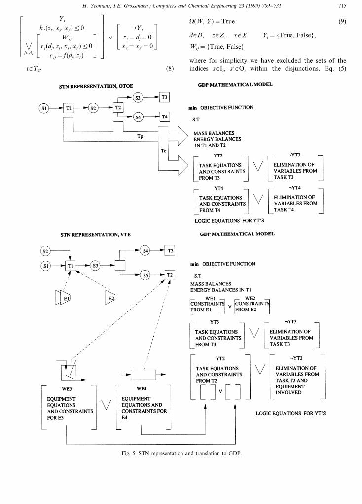
Eq. (1) represents the objective function in terms ofcosts incurred by the selection of a task with its equip-ment, and variable costs associated with flows throughthe different states. Eq. (2) represents the mass andenergy balances, as well as the design constraints of allthe tasks that are permanent throughout the flowsheet.In Eq. (3), the selection of a conditional task t�TC isrepresented by a Boolean variable. When the value ofthe variable is true (Yt) the task is selected. When theconditional task is not selected (Yt=False), it is as-sumed for ease of notation that all the correspondingvariables are set to zero. Eq. (4) represents the logicrelations between Boolean variables in formulation(PSTN-1). Fig. 5(a) presents qualitatively the elementsof the model with those of the STN/OTOE representa-tion for a small example.
For the case of VTE assignment, another type ofdisjunction must be introduced since the equipmentassignment must be determined. For each task (eitherpermanent or conditional) it is necessary to select oneand only one of the equipment configurations availablefor the task. To model this disjunction define for everytask t the set At={ j�E � equipment j can be assignedto task t}, and define Wjt as a Boolean variable thatindicates whether equipment j will perform task t. Thegeneral STN/VTE model is as follows:
(P-STN2): min %t�T
%j�E
ctj+ %s�S
asxs (5)
s.t. ht(zt, xs, xs%)50 t�Tp (6)
0j�At
ÃÆ
È
Wtj
r j(dj, zt, xs, xs’)50ctj= f(dj, zt)
ÃÇ
Ét�TP (7)
ÃÆ
È
Yt
gt(dj, zt, xs, xs%)50ct= f(dj, zt)
" j %�Qt j %�Qs�I t, s %�Ot
ÃÇ
É�ÃÆ
È
¬Yt
dj %=zt=0xs=xs%=0
" j %�Qt
Ö s�I t, s %�Ot
ÃÇ
Ét�Tc (3)
H. Yeomans, I.E. Grossmann / Computers and Chemical Engineering 23 (1999) 709–731 715
ÃÃ
Ã
Æ
È
Yt
ht(zt, xs, xs%)50
0j�At
ÃÆ
È
Wtj
r j(dj, zt, xs, xs%)50ctj= f(dj, zt)
ÃÇ
É
ÃÃ
Ã
Ç
É
�ÃÆ
È
¬Yt
zt=dj=0xs=xs%=0
ÃÇ
É
t�TC (8)
V(W, Y)=True (9)
d�D, z�Z, x�X Yt={True, False},
Wtj={True, False}
where for simplicity we have excluded the sets of theindices s�It, s %�Ot within the disjunctions. Eq. (5)
Fig. 5. STN representation and translation to GDP.

H. Yeomans, I.E. Grossmann / Computers and Chemical Engineering 23 (1999) 709–731716
represents the objective function in terms of investmentcost incurred by the assignment of an equipment to aselected task, and variable costs generated by the states.Eq. (6) represents the equations and constraints that arevalid for all the flowsheet due to the tasks that arepermanent. Eq. (7) represents disjunctions correspond-ing to the different equipment for which the permanenttasks in (Eq. (6)) can be performed. The Booleanvariables Wtj control the application of the constraintsfor equipment ( j�At) for the given permanent taskt�TP. Eq. (8) represents the constraints and equationsfor the conditional tasks t�TC. If the conditional taskexists (Yt=True), the outermost brackets of the lefthand side enforce the corresponding equations andconstraints. If a conditional task does not exist (Yt=False), the right hand side brackets include the vari-ables to be set to zero. If a conditional task is selected,there is a choice of equipment j�At where it can beperformed, given by the innermost bracket that con-tains the corresponding equations and constraints. Fi-nally, Eq. (9) represents the logic relations between theBoolean variables in the formulation (PSTN-2). Fig.5(b) shows qualitatively the relation between the STN/VTE representation and its GDP model.
4.5. GDP model for the SEN representation
Let the equipment in a flowsheet be divided into twosets: E=EP@EC, where EP represents the equipmentthat is permanent for all synthesis alternatives, and EC
represents the conditional equipment. Also, define theset Bj={t�T � task t can be performed in equipmentj }. The Boolean variable Uj represents whether condi-tional equipment j exists, while the Boolean variable Vtj
represents whether task t is performed in equipment j.The equations and constraints that are activated whentask t is performed in equipment j is defined byptj(dj, zt, xs, xs%). The GDP model for the SEN represen-tation is as follows,
(P-SEN): min %j�E
%t�T
cjt+ %s�S
asxs (10)
s.t. 0t�Bj
ÃÆ
È
Vjt
ptj(dj, zt, xs, xs%)50c jt= f(dj, zt)
ÃÇ
Éj�EP (11)
ÃÃ
Ã
Æ
È
0t�Bj
Uj
ÃÆ
È
Vjt
ptj(dj, zt, xs, xs%)50ctj= f(dj, zt)
ÃÇ
É
ÃÃ
Ã
Ç
É
�ÃÆ
È
¬Uj
zt=dj=0xs=xs%=0
ÃÇ
É
j�EC (12)
V(V, U)=True (13)
d�D, z�Z, x�X, Vjt={True, False},
Uj={True, False}
Eq. (10) is the objective function that includes thefixed cost for task t performed in equipment j, and thevariable cost from the flow of materials through thedifferent states in the flowsheet. Eq. (11) corresponds tothe disjunctions that apply for the permanent equip-ment. Each disjunction is used to model the selection oftasks t�Bj for each equipment j�EP for which theBoolean variable Vjt is used. Eq. (12) has two nesteddisjunctions because it is necessary to determine if aconditional equipment will exist (Uj=True), and oncedetermined it is necessary to select a task t�Bj that theequipment j�EC can perform (Vjt=True). Notice thatif an equipment is not selected, the variables thatparticipate on it are set to zero, as it happens in(PSTN-1) and (PSTN-2). Fig. 6 shows for a smallexample the relation between the SEN representationand its model.
4.6. Remarks
It is clear from the models (P-STN1), (P-STN2) and(P-SEN) that their mathematical structure is quite dif-ferent. Not surprisingly, (P-STN1) for the STN/OTOErepresentation, has the simplest structure with disjunc-tions involving only two terms. In contrast, both (P-STN2) and (P-SEN) involve embedded disjunctionswith multiple terms.
Two interesting theoretical questions on the abovemodels, are first whether they become equivalent undersome limiting conditions, and second whether any ofthem are inherently ‘tighter’, and thereby produce mod-els that are in principle easier to solve.
On the first question, it is clear that for the OTOEassignment, (P-STN2) reduces to (P-STN1) since in thatcase Qt=At Öt�T, with which the Boolean variablesWtj can be eliminated. Furthermore, if OTOE assign-ments are considered for the SEN network, then model(P-SEN) is also reduced to model (P-STN1) because theset Bj has only one task element given by the one in theset Qj and E=T. Hence, the Boolean variables Vjt canbe eliminated, leading to the structure of (P-STN1) bysetting ptj=gt. For the VTE assignment case, both(P-STN2) and (P-SEN) lead to different models. It isalso possible to model a physically equivalent problemwith the (P-STN1) and (P-SEN) models, as will beshown in the distillation example later in the paper.
On the question about tightness, the numerical re-sults will show that in the simpler case (distillationsequencing with no heat intergration) the SEN model isnot always tighter than the STN model, while in themore complex case (see problem with heat integration)

H. Yeomans, I.E. Grossmann / Computers and Chemical Engineering 23 (1999) 709–731 717
Fig. 6. Transformation of the SEN Representation into GDP a model.
the STN model was tighter. Therefore, unless specificmodels are considered, it appears that no general prop-erty of tightness can be established between the (P-STN2) and (P-SEN) models.
4.7. Transformation of GDP models into MILPproblems
Several strategies have been developed to solve math-ematical programming problems in disjunctive form.For instance, Beaumont (1991), Raman and Gross-mann (1994) and Hooker and Osorio (1996) have devel-oped algorithms to solve disjunctive linear problems,while Turkay and Grossmann (1996a) developed analgorithm to solve disjunctive non-linear problems.These methods involve algorithms that are still in theearly stages of development and implementation, andtherefore, are generally not yet comparable in terms ofspeed and ease of solution, particularly in the case of
MILP models. Since the problems presented in thispaper are linear, we will focus on the reformulation ofthe GDP problems of the previous sections into MILPproblems.
Because of the nature of GDP, it is possible totransform in a systematic way the synthesis models(P-STN1), (P-STN2) and (P-SEN) into MILP formusing the convex hull formulation of the disjunctions(Balas, 1985). The convex hull formulation is based onthe disaggregation of variables that gives the tightestcontinuous relaxation of the disjunctions. In particular,consider the linear disjunction:
0i�D
� %j�N
aijxj5bin
(14)
The convex hull formulation of Eq. (14) is given by thefollowing constraints, where z j
i are the disaggregatedvariables for xj and N is the index set of the continuousvariables x,
H. Yeomans, I.E. Grossmann / Computers and Chemical Engineering 23 (1999) 709–731718
xj=%i
z ji, j�N (15)
%j�N
aijz ji5biyi, i�D, (16)
05z ji5Ujyi, i�D, (17)
%i
yi=1, yi=0, 1 (18)
Eq. (16) represents each term of the disjunction withdisaggregated variables z j
i and right hand side multipliedby the binary variable yj. Eq. (18) ensures that only onedisjunction holds, while the inequalities in Eq. (17)ensure that disaggregated variables for terms in thedisjunction that do not apply be set to zero. A directderivation of these constraints is given in Turkay andGrossmann (1996b). The application of the convex hullof disjunctions will be illustrated with the synthesisproblem described in the next section.
5. General synthesis framework for optimal distillationsequences
The objective of the problem considered here is toseparate a multicomponent mixture into its individualcomponents at minimum cost using sharp separators.According to the systematic framework proposed in thispaper, the first step is to determine the representation of
design alternatives. If the STN representation is used,one can specify either a OTOE assignment, or a VTEassignment. The STN/OTOE representation will beused, and compared with an SEN model in whichcolumns can perform multiple separation tasks.
5.1. STN representation
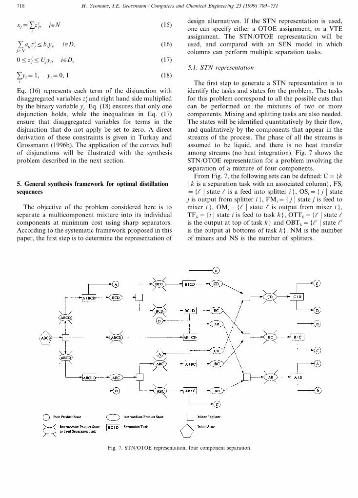
The first step to generate a STN representation is toidentify the tasks and states for the problem. The tasksfor this problem correspond to all the possible cuts thatcan be performed on the mixtures of two or morecomponents. Mixing and splitting tasks are also needed.The states will be identified quantitatively by their flow,and qualitatively by the components that appear in thestreams of the process. The phase of all the streams isassumed to be liquid, and there is no heat transferamong streams (no heat integration). Fig. 7 shows theSTN/OTOE representation for a problem involving theseparation of a mixture of four components.
From Fig. 7, the following sets can be defined: C={k� k is a separation task with an associated column}, FSi
={l � state l is a feed into splitter i }, OSi={ j � statej is output from splitter i }, FMi={ j � state j is feed tomixer i }, OMi={l � state l is output from mixer i },TFk={i � state i is feed to task k}, OTTk={l � state lis the output at top of task k} and OBTk={l% � state l%is the output at bottoms of task k}. NM is the numberof mixers and NS is the number of splitters.
Fig. 7. STN/OTOE representation, four component separation.
H. Yeomans, I.E. Grossmann / Computers and Chemical Engineering 23 (1999) 709–731 719
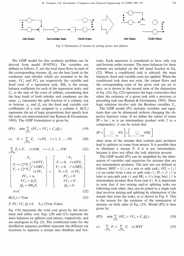
Fig. 8. Elimination of streams by joining mixers and splitters.
The GDP model for this synthesis problem can bederived from model (P-STN1). The variables aredefined as follows: Fl are the total mass flows in each ofthe corresponding streams, Qk are the heat loads in thecondenser and reboiler which are assumed to be thesame, VCk and FCk are respectively the variable andfixed costs of a separation task, HKk is the energybalance coefficient for each of the separation tasks, andCU is the sum of the costs of utilities, considering thatthe heat loads of both reboiler and condenser are thesame. jk represents the split fraction of a column, topor bottom. ak and bk are the fixed and variable costcoefficients of a task assigned to a column k. V(Yk)represents the set of logic propositions that specify howthe tasks are interconnected (see Raman & Grossmann,1993). The GDP formulation is given by:
(P1): min %k�C
(FCk+VCk+CUQk) (19)
s.t. Fl= %j�OSi
Fj l�FSi i=1, 2, ... , NS (20)
%j�FMi
Fj=Fl l�OMi i=1, 2, ... , NM (21)
ÃÃ
Ã
Ã
Ã
Æ
È
Yk
Fl=jktopFi
Fl’=jkbotFi
"l�OTTk
l’�OBTk
i�TFk
FCk=ak
VCk=bkFi
Qk=HKkFi
ÃÃ
Ã
Ã
Ã
Ç
É
�ÃÃ
Ã
Ã
Ã
Æ
È
¬Yk
Fl=0, l�OTTk
Fl’=0, l%�OBTk
Fi=0, i�TFk
FCk=0VCk=0Qk=0
ÃÃ
Ã
Ã
Ã
Ç
Ék�C (22)
V(Yk)=True (23)
F, FC, VC, Q]0, Yk�{True, False}
Eq. (19) represents the total cost given by the invest-ment and utility cost. Eqs. (20) and (21) represent themass balances on splitters and mixers, respectively, andare analogous to Eq. (2). The conditional tasks for thedistillation sequence problem represent the different cutlocations to separate a stream into distillate and bot-
toms. Each separator is considered to have only topand bottom outlet streams. The mass balances for thesestreams are included on the left hand bracket in Eq.(22). When a conditional task is selected, the massbalances, fixed and variable costs are applied. When theconditional task does not exist, the output flows andthe corresponding costs of the given task are set tozero, as is shown in the second term of the disjunctionin Eq. (22). Eq. (23) represents the logic constraints thatrelate the existence of a given task with a previous orpreceding task (see Raman & Grossmann, 1993). Theselogic relations involve only the Boolean variables Yk.
The GDP model (P1) includes variables and equa-tions that can be eliminated without changing the ob-jective function value. If we define the subset of statesIP={m � m is an intermediate product with 2 to ncomponents}, it can be noted that
IP=� .
i=1, ... , NS
FSin@� .
i=1, ... , NM
OMin
since none of the streams that contain pure productslead to splitters or come from mixers. It is possible thento eliminate a stream Fl if it is not intermediate,because it does not affect the task selection process.
The GDP model (P1) can be simplified by the elimi-nation of variables and equations for streams that arenot intermediate products. The new sets are defined asfollows: MST={i � i is a mix or split task}, OTi={ j �j is an outlet from a mix or split task i }, ITi={l � l isinlet to mix/split task i } and SPk={l�{top, bot} � l isintermediate product flow from task k}. It is importantto note that if two mixing and/or splitting tasks arefollowing each other, they can be joined in a single taskthat involves mixing and splitting by elimination of thestream that joins the tasks, as is shown in Fig. 8. Thisis the reason for the existence of the summation ofstreams on both sides of Eq. (25). Model (P2) is thengiven by:
(P2): min %k�C
(FCk+VCk+CUQk) (24)
s.t. %l�ITi
Fl= %j�OTi
Fj i�MST (25)

H. Yeomans, I.E. Grossmann / Computers and Chemical Engineering 23 (1999) 709–731720
ÃÃ
Ã
Æ
È
Yk
Fl=jkmFi
FCk=ak
VCk=bkFi
Qk=HKkFi
ÃÃ
Ã
Ç
É
�ÃÃ
Ã
Æ
È
¬Yk
Fl=0, Fi=0FCk=0VCk=0Qk=0
ÃÃ
Ã
Ç
É
k�C (26)
V(Yk)=True (27)
F, FC, VC, Q]0, Yk�{True, False}
where for simplicity we are not showing the followingindices inside the disjunctions: i�TFk, l�SPk, andm�IP. To transform model (P2) into MILP form, theconvex hull formulation of Eqs. (15)–(18) is appliedto the disjunctive program shown above. After re-ordering the equations and replacing the general massbalances with variables in the disjunctions, model (P3)is derived in terms of the binary variables yk={0, 1},which are associated to the existence of each column,and hence separation task. The new sets are as fol-lows: FIS={k � k is the split after initial state},IPSm={l � l is product stream from task k},IFSm={ j � j is intermediate feed state for task k},IP={intermediate products m}.
(P3): min %k�C
(akyk+bkFk+CUQk) (28)
s.t. %k�FIS
Fk=Ftotal (29)
%l�IPSm
Fl− %j�IFSm
j jmFj=0 m�IP (30)
Qk−HKkFk=0 k�C (31)
Fk−Uyk50 k�C (32)
Ay5a (33)
Fk, Qk]0, yk=0, 1 k�C
Eq. (29) represents the mass balance for the initialsplitter in terms of the total flow, Ftotal, to be pro-cessed. Eq. (30) represents the substitution of the dis-aggregated equations from the convex hull of theconditional task disjunctions into the permanentmixer and splitter equations. Eqs. (31) and (32) areequations for heat loads and flows from the disjunc-tions for conditional tasks. Eq. (33) represents thelogic constraints for interconnection of tasks in (Eq.(26)), now transformed into algebraic equations withbinary variables (see Raman & Grossmann, 1993).
It is interesting to note that the MILP formulation(P3) corresponds exactly to the one proposed by An-drecovich and Westerberg (1985) with the addition ofthe logic constraints in (Eq. (32)). Thus, this exampleshows that the proposed framework can be used tosystematically derive models reported in the literature.
The STN model (P1) for the synthesis of sharpdistillation sequences is based on the OTOE assign-ment. It is possible to generate a model for the VTEassignment, which will include costs that are differentif a task is performed in a different column. Theappendix includes the general model for the VTE ap-proach.
5.2. SEN representation
To construct the SEN representation, it is necessaryto define the states involved in a problem, as well asthe number and characteristics of the equipment thatare available. The states for the problem consideredare the same as the ones defined for the STN repre-sentation. Engineering criteria are used to fix thenumber of columns and the tasks they can perform,which will be implicitly included in the representation.Since four components are involved in the originalmixture, we can select three columns to perform theseparation into pure components. This is providedthat we allow each column to perform multiple sepa-ration tasks, in contrast to the OTOE assignment thatwe considered for the STN model.
The SEN representation for the separation of afour component mixture is shown in Fig. 9. Notethat three columns are considered for the four com-ponent mixture (i.e. N−1 for N components), andthe split C/D is considered in columns 2 and 3 inorder to accommodate the sequence where split AB/CD is performed in the first column. Note also thatthe states cannot be defined independently of the taskto be performed in the equipment, since the selectionof a task in the equipment will determine the propervalue of a state. There can be logic constraints thatwill eliminate or activate streams depending on thetask selected for a given equipment.
From (P-SEN), the GDP model for the SEN repre-sentation in Fig. 9 can be derived by introducingthe Boolean variables Yik to select task i for columnk. Note that since the number of columns is known,there is no need to introduce Boolean variablesfor the units. Defining the sets Dk={l � l isdistillate stream out of column k}, Bk={l% � l% isbottom stream out of column k}, TCk={i � i is atask allowable for column k}, leads to the followingmodel:
(P4): min %k�C
(FCk+VCk+CUQk) (34)
s.t. Fl= %j�OSi
Fj l�FSi i=1, ... , NS (35)
%j�FMi
Fj=Fl l�OMi i=1, ... , NM (36)

H. Yeomans, I.E. Grossmann / Computers and Chemical Engineering 23 (1999) 709–731 721
0Öi�TCk
ÃÃ
Ã
Ã
Ã
Æ
È
Yik
Fl=j itopFk, l�Dk
Fl’=j ibotFk, l’�Bk
FCk=ai
VCk=biFk
Qk=HKiFk
ÃÃ
Ã
Ã
Ã
Ç
É
k�C (37)
V(Yik)=True (38)
F, FC, VC, Q]0, Yik�{True, False}
Eq. (34) is the objective function identical to the one in(P1). Eqs. (35) and (36) represent the mass balances insplitters and mixers, respectively, where the mixer/splitteris permanent equipment with only one task and noassociated fixed or variable cost. Eq. (37) represents thedisjunction for the selection of the task to be performedin each of the three columns. The terms in the bracketsrepresent the equations that will be applied when the taskassociated with the Boolean variable Yik is selected. Eq.
(38) represents the logic relations for the existence ofdifferent tasks in the different columns.
A detailed analysis of the formulation (P4) and therepresentation for distillation sequences allows us tosimplify its GDP model. Since the SEN representationhas a fixed number of columns for the number ofcomponent in a mixture, it is implicit in the superstructurethat only one separation path can be performed. This factis not implicit in the STN representation, but it wasimposed through the logic constraints. Because only oneseparation sequence can be used, it can be shown thatthe mixers and splitters in the SEN representation willhave only one active inlet or outlet respectively. This factallows to move their equations inside the disjunctions forthe discrete tasks. It is also possible to change the definitionof the split fraction of each separation, jik, so that theyare referred to the total flow that inputs to the sequence.Problem (P5) shows the resulting GDP model.
(P5): min %k�C
(FCk+VCk+CUQk) (39)
Fig. 9. SEN representation for the separation of a four component mixture.

H. Yeomans, I.E. Grossmann / Computers and Chemical Engineering 23 (1999) 709–731722
Table 1Comparison between STN and SEN representation for distillation sequences.
Criteria 6 Component separation5 Component separation4 Component separation
SEN MILP STN MILPSTN MILP SEN MILP STN MILP SEN MILP(P6)(P6) (P3)(P3)(P3) (P6)
181 157Constraints 43 75 88 344106157 302Variables 6131 68
20 28 35 46Binary vars. 10 114304.00 18161.56Relaxed sol. 3623.81 3625.81 4278.34 18030.18
18170.354304.00 18170.26Integer sol. 4304.083625.81 3625.812 1 10B&B nodes 22 1
12016552Iterations 5330 170.430.47CPU time a 0.14 0.13 .14 0.20
a Using GAMS/OSL in a HP 9000/712.
s.t. 0i�TCk
ÃÃ
Ã
Æ
È
Yik
Fl=jikFtotal
FCk=aik
VCk=bikFl
Qk=HKikFl
ÌÃ
Ã
Â
Å
l�ICk
ÃÃ
Ã
Ç
É
k�C (40)
V(Yik)=True (41)
F, FC, VC, Q]0, Yik�{True, False}
where ICk={l � l is the inlet flow to column k} andjik is the split fraction of the intermediate mixturereferred to the total mass flow when task i is per-formed in column k. The reduced GDP formulation(P5) can be transformed into an MILP model (P6) bymeans of the convex hull formulation of disjunctionsintroduced by Eqs. (15)–(18) and by redefining Fk asthe inlet flow to column k.
(P6): min %k�C
(FCk+VCk+CUQk) (42)
s.t. Fk= %i�TCk
fki
FCk= %i�TCk
fcki
VCk= %i�TCk
6cki
Qk= %i�TCk
qki
ÌÃ
Ã
Ã
Ã
Ã
Ã
Â
Å
k�C (43)
fki=jkiFtotalyik
fcki=aikyik
6cki=bi fki
qki=HKi fki
ÌÃ
Ã
Â
Å
k�Ci�TCk
(44)
%i�TCk
yik=1 k�C (45)
Ay5b (46)
F, f, FC, fc, VC, 6c, Q, q]0, yik�{0, 1}
Eqs. (45) and (46) represent the logic relations be-tween tasks and equipment expressed in algebraicform with binary variables.
The SEN representation can be useful for retrofitproblems if Boolean variables and logic constraintsare added to eliminate or activate streams that areassociated with the repiping and layout of the givensystem. This might be done in the form of new dis-junctions, or in the form of extra constraints withinthe existing disjunctions.
5.3. Comparison between STN and SEN in numericalexamples
To compare the performance of the SEN repre-sentation with that of the STN/OTOE, distillationsequence problems with four, five and six compo-nents were solved. The problem data can be foundin Raman and Grossmann (1993). Table 1 showsthe results of both models, (P3) and (P6), respec-tively.
Model (P6) solves the four and five componentproblem at the root node of the B&B tree, and model(P3) requires two nodes for the same problems. How-ever, when the number of components increases, theSTN B&B requires a larger number of nodes than theSEN, even though the solution times are comparable.This behavior suggests that the computational com-plexity of the SEN problems is higher.
Finally, it is worth noting that the differences be-tween the number of equations and variables for theSTN and SEN models are due to the different typeof disjunction used. When the disjunctions of theSEN are disaggregated they introduce a larger num-ber of continuous and binary variables in proportionto the number of tasks each equipment can perform.However, this disadvantage is offset by the specificknowledge that is used in the SEN representation(number of columns, tasks they perform).

H. Yeomans, I.E. Grossmann / Computers and Chemical Engineering 23 (1999) 709–731 723
6. Synthesis of sharp distillation sequences with heatintegration
The synthesis of distillation sequences that has beenconsidered in the previous sections takes into accountonly the mass balances. The SEN and STN represen-tations, however, can also include tasks that performenergy transfer. In this section, we will extend theSTN and SEN representations for the synthesis ofsharp distillation sequences to include energy balancesand possibilities of heat integration.
In order to keep the models linear, the problemwill be simplified as in Raman and Grossmann(1993), who proposed a heat integrated model for dis-tillation sequences where the cost of columns op-erating at different pressures is represented througha linear function of the temperature in the conden-ser. To perform the heat integration it is necessaryto include the temperatures of reboilers and con-densers as variables to verify the feasibility of heatexchange.
6.1. STN representation and GDP model
In order to consider heat integration, the followingapproach will be used in this work. First, heat trans-fer tasks will be introduced in the STN/OTOE net-work in which the only change considered is the heatcontent of the corresponding streams. The heat trans-fer tasks can be reduced to source or sink nodesdepending on whether they release or absorb heat. Toaccount for the heat integration, all the heat transfertasks will be integrated in a block for heat recoveryas in Raman & Grossmann (1994). For the case ofisothermal streams, such as is the case of this dis-tillation problem, the block may consist of all possi-ble matches for heat exchange (see Fig. 10).Alternatively, one might use the aggregated modelsby Duran and Grossmann (1986), Grossmann,Yeomans and Kravanja (1998) or the detailed HENsuperstructure by Yee, Grossmann and Kravanja(1990).
In Fig. 10, note that each distillation task that wasintroduced in the previous section has four outletstates. Two of them involve mass flows, while theother two are for heat transfer. The heat exchangernetwork is based on stream splitting and has noequipment in series.
To model the problem, it was considered that thecolumns have a linear cost relation with the tempera-ture of the condenser, and that the costs of the heatexchangers are not included. The Boolean variable(Yk) is defined for the distillation tasks k�C, whilethe Boolean variable Zkj represents the match be-tween the heat source (QCk) from distillation task k
(condensers at temperature TCk) and the heat sink(QRj) of distillation task j (reboiler at temperatureTRj). ZCkn and ZSkm represent the match of heatsource in distillation task k with cold utility n, andthe match of heat sink from task k with hot utilitym, respectively. The continuous variables QXkj, QWkn
and QSkm represent the corresponding exchanges ofheat. The parameter DRCk represents the temperaturedifference between reboiler and condenser if separa-tion task k takes place, TWL is the temperature ofthe coldest cooling utility, EMAT is the minimumapproach temperature that is required for feasibleheat exchange, U is an upperbound for the tempera-tures, and UQ is an upperbound on the heat ex-changes. The model is as follows:
(P7):
min %k�C
�DPk+bkFk+ %
m�HU
(pumQSkm)
+ %n�CU
(punQWkn)n
(49)
s.t. %l�ITk
Fl= %j�OTk
Fj k�MST (50)
QCk= %h�CU
QWnk+ %j�C¯k
QXkj k�C (51)
QRk= %m�HU
QSmk+ %j�C¯k
QXjk k�C (52)
ÃÃ
Ã
Ã
Ã
Ã
Ã
Æ
È
Yk
Fl=jkmFi, Öi�TFk, Öl�IPk
QCk=HKkFk
QRk=HKkFk
TCk=TRk−DRCk
DPk=akTCk
TWL+EMAT
ÃÃ
Ã
Ã
Ã
Ã
Ã
Ç
É
�
ÃÃ
Ã
Æ
È
¬Yk
Fl=0, Öl�IPk
QCk=QRk=0TCk=TRk=0
DPk=0
ÃÃ
Ã
Ç
É
k�C (53)
ÃÆ
È
Zkj
TCk]TRj+EMATQXkj5UQ
ÃÇ
É�ÃÃ
Ã
Æ
È
¬Zkj
TCk5UTRj5UQXkj=0
ÃÃ
Ã
Ç
É
k, j�Ck" j
(54)

H. Yeomans, I.E. Grossmann / Computers and Chemical Engineering 23 (1999) 709–731724
ÃÆ
È
ZCkn
TCk]TWn+EMATQWkn5UQ
ÃÇ
É�ÃÆ
È
¬ZCkn
TCk5UQWkn=0
ÃÇ
É
k�Cn�CU
(55)
ÃÆ
È
ZSkm
TRk5TSm−EMATQSkm5UQ
ÃÇ
É�ÃÆ
È
¬ZSkm
TRk5UQSkm50
ÃÇ
É
k�Cm�HU
(56)
V(Y, Z, ZS, ZC)=True (57)
TC, TR, F, QX, DP, QS, QW]0,
Y, Z, ZC, ZS={True, False}
The objective function in (Eq. (49)) is expressed interms of the investment cost, given by the fixed chargeDPk and variable cost term bkFk, and in terms of thehot and cold utility costs with corresponding prices, pum
and puh. Eqs. (51) and (52) represent the energy bal-ances for each condenser and heat exchanger, andequations Eqs. (54)–(56) enforce feasible temperature
Fig. 10. STN representation for the synthesis of heat integrated distillation sequences.

H. Yeomans, I.E. Grossmann / Computers and Chemical Engineering 23 (1999) 709–731 725
differences if the corresponding match is performed.Eq. (50) corresponds to Eq. (25) in the STN model(P1), while equation Eq. (53) is similar to equation Eq.(26) plus the temperature difference for reboiler andcondenser, as well as the fixed cost expressed as afunction of the temperature in the condenser. The logicconstraints in (Eq. (57)) include the relations that per-mit heat transfer only if the distillation column con-nected to it is active. These relations are importantbecause heat and mass transfer are treated separately.Notice that the model includes the possibility of usingmultiple utilities, represented by the sets CU and HUfor cooling and heating utilities, respectively.
If the convex hull formulation is applied to eachdisjunction in model (P7) (see Eqs. (15)–(18)), andappropriate simplifications are made, the followingMILP model is obtained:
(P8):
min %k�C
�DPk+bkFk+ %
m�HU
(pumQSkm)
+ %n�CU
(punQWkn)n
(58)
s.t. %i�FIS
Fi=Ftotal (59)
%l�IPSm
Fl− %j�IFSm
j jmFj=0 m�IP (60)
HKkFk= %h�CU
QWhk+ %j�DT¯k
QXkj k�C (61)
HKkFk= %m�HU
QSmk+ %j�DT¯k
QXjk k�C (62)
TCk=TRk−DRCkyk k�C (63)
DPk=akTCk
TWL+EMATk�C (64)
Fk5Ftotalyk
TCk5Uyk
TRk5Uyk
ÌÂ
Åk�C (65)
TCk=TC1kjX +TC2kj
X
TRk=TR1kjX +TR2kj
X
"j, k�C, k" j
TCk=TC1knW +TC2kn
W k�C, n�CU
TRk=TR1kmS +TR2km
S k�C, m�HU (66)
TC1kjX]TR1jk
X +EMATzkj
QXkj5UQzkj
TC1kjX5Uzkj
TR1jkX5Uzkj
TC2kjX5U(1−zkj)
TR2jkX5U(1−zkj)
ÌÃ
Ã
Ã
Ã
Â
Å
k, j�Ck" j
(67)
TR1kmS 5 (TSm−EMAT)zskm
QSkm5UQzskm
TR1kmS 5Uzskm
TR2kmS 5U(1−zskm)
ÌÃ
Ã
Â
Å
k�Cm�HU
(68)
TC1knW] (TWn+EMAT)zckn
QWkn5UQzckn
TC1knW5Uzckn
TC2knW5U(1−zckn)
ÌÃ
Ã
Â
Å
k�Cn�CU
(69)
[yT, zT, zsT, zcT]TAT5aT (70)
TC, TR, F, QX, DP, QS, QW]0, y, z, zc, zs={0, 1}
TC1, TC2, TR1, TR2]0
In the equations above, recall that FIS={i � i is asplit of the initial stream}, IP={m � m is an intermedi-ate product}, IPSn={l � l is product stream from taskk}, and IFSn={ j � j is intermediate feed state for taskk}. The Boolean variables in (P7) are replaced by theircorresponding binary variables in lowercase. Eqs. (59)and (60) were derived in similar fashion to the ones in(P3), after the same variable and equation reduction.Eqs. (61) and (62) are also derived after applying theconvex hull to (Eq. (53)) and substituting variables inEqs. (51) and (52). Eqs. (63) and (64) correspond tothose equations inside disjunction (Eq. (53)) that couldnot be reduced. Eq. (65) includes the binary variablesthat will control the selection of a given task, and willtherefore affect Eqs. (59)–(64). Eq. (66) includes thedisaggregation of variables for the disjunction sets (Eqs.(54)–(56)), after the application of the convex hullformulation. Eqs. (67)–(69) correspond to the rest ofthe convex hull formulation, for exchange betweenreboiler and condenser (Eq. (67)), condenser and cool-ing water (Eq. (68)), and reboiler and steam (Eq. (69)).Finally, Eq. (70) represents the logic relations betweenseparation and heat exchange tasks, given in algebraicexpressions.
It is possible to generate an STN/VTE representationfor this problem, but it will not be shown here becausethe interest of this section is to reproduce existingmodels in order to demonstrate the representation andmodeling framework presented in this paper.
6.2. SEN representation and modeling of heatintegrated distillation sequences
For the SEN representation of the synthesis of heatintegrated sharp distillation sequences, the heat ex-change part will be based on similar superstructurecriteria used for the STN model (e.g. stream splittingand parallel exchangers). The part corresponding to thedistillation will be treated in the same way as in non-in-tegrated distillation sequences.

H. Yeomans, I.E. Grossmann / Computers and Chemical Engineering 23 (1999) 709–731726
Fig. 11. SEN representation for the separation of a three component mixture with heat integration.
Since the SEN representation requires first to deter-mine the equipment and states involved, it is necessaryto select the number of distillation columns and heatexchangers that will be involved in the superstructure.For the representation shown in Fig. 11, the minimumnumber of columns and exchangers was chosen (num-ber of columns=N−1, where N is number of compo-nents to separate).
The same consideration of heat flows that are treatedindependently of the mass flows for the STN represen-tation can be applied to the SEN. The heat flows willnow be related to equipment units instead of tasks.
The intermediate states before and after the heattransfer operations have been omitted in the representa-tion for clarity purposes. Note that the representationin Fig. 11 covers all the possible equipment matches forheat transfer, but this is performed by postulatingseveral exchangers for which no specific heat exchangetask is pre-assigned (see also Yee & Grossmann, 1991).Note that it is possible to only have a match amongeither the first column reboiler and the second columncondenser or vice versa, but not both. Also, the possi-bility of both reboilers in Fig. 10 being operated withsteam, and both condensers with cooling water is con-sidered. This is an example of the application of engi-neering knowledge when constructing the SENrepresentation.
Let C={k � k is an available column}, E={ j � j isan exchanger}, TCk={i � i is a task to be performed by
column k}, ECk ={i � i is a heat exchanger that canremove heat from condenser in column k}, ERk={ j �j is a heat exchanger that can provide heat to reboiler incolumn k}, EE={l � l is the set of exchanger equip-ment}, SOk={i � i is a heat source for exchanger l},SIl={ j � j is a heat sink for exchanger l}.
The variable definition is as follows: QRk% representsthe amount of heat required by the reboiler in columnk %. QCk is the amount of heat to be removed in thecondenser of column k. QXkk’ is the amount of heatexchanged between condenser of column k and reboilerof column k %. QXWkn is the heat exchanged betweencondenser k and cooling utility n. QXSk%m is the heatexchanged between reboiler k % and heating utility n.The GDP model (P9) is then as follows:
(P9):
min %k�C
�(DPk+VCk)+ %
m�HU
(pumQXSk%m)
+ %n�CU
(punQXWkn)n
(71)
s.t. Fl= %j�OSi
Fj Öl�FSi, i=1, ... , NS (72)
%j�FMi
Fj=Fl Öl�OMi, i=1, ... , NM (73)
QCk= %k%"k
QXkk%+ %n�CU
QXWkn k�C (74)

H. Yeomans, I.E. Grossmann / Computers and Chemical Engineering 23 (1999) 709–731 727
QRk%= %k"k%
QXkk%+ %n�HU
QXSk%n k %�C (75)
TCi=TRi−DTCi i�T (76)
Yik
Fl=j itopFk, l�Dk
Fj=j ibotFk, j�Bk
DPk=aiTCk
TWL+EMAT0i�TCk
ÃÃ
Ã
Ã
Ã
Ã
Ã
Ã
Ã
Æ
È
ÃÃ
Ã
Ã
Ã
Ã
Ã
Ã
Ã
Ç
É
k�C (77)VCk=biFk
QCk=QRk=HKiFk
TCk=TCi
TRk=TRi
ÃÃ
Ã
Æ
È
Zj
0k, k%�Ck"k%
ÃÆ
È
Wjkk%
Qj=QXkk%
TCk]TRk%+EMATÃÇ
É
0n�CUk�C
ÃÆ
È
Wjkn
Qj=QXWkn
TCk]TRk%+EMATÃÇ
É
0m�HU
k�C
ÃÆ
È
Wjkm
Qj=QXSk%m
TSm]TRk+EMATÃÇ
ÉÃÃ
Ã
Ç
É
�� ¬Zj
Qj=0n
j�E
(78)
V(Y, W, Z)=True (79)
TC, TR, F, QXC, QXR, QC, QR, DP, QCso, QRsi, FC, VC]0,
Yik={True, False}, Zj={True, False},
Wij={True, False}
In model (P9), Eq. (71) is the objective function interms of fixed and variable costs. Note that HU is asubset of SOl and CU is a subset of SIl. Eqs. (72) and(73) represent the mass balances in all the mass splittersand mixers, while Eqs. (74) and (75) represent theenergy balances in the heat mixers and splitters. Eq.(76) represents the thermodynamic constraint for tem-perature difference in every column. Eq. (77) is thedisjunction of tasks for the permanent columns, andinclude mass balances, energy balances and thermody-namic constraints for the column. Eq. (78) representsthe disjunction for the conditional heat exchangers,where the task that represents the match of hot andcold streams in the exchanger is given by the innermostdisjunction, selected by the Boolean variable Wij. Whena heat exchanger is not used (Zj=False), the heat
exchange variables are set to zero, and the thermody-namic temperature difference constraint is not enforced.Finally, Eq. (66) represents the logic connectivity be-tween columns, exchangers and heat exchange matches.
The SEN model (P9) can be transformed in MILPform using the convex hull formulation of disjunctions,leading to model (P10).
(P10):
min %k�C
�(DPk+VCk)+ %
m�HU
(SPmQXSkm)
+ %n�CU
(WPnQXWkn)n
s.t. Fl= %j�OSi
Fj l�FSi, i=1, ... , NS (80)
%j�FMi
Fj=Fl l�OMi, i=1, ... , NM (81)
QCk= %k%"k
QXkk%+ %n�CU
QXWkn k�C (82)
QRk’= %k"k’
QXkk%+ %n�HU
QXSk%n k ’�C (83)
Fl= %i�TCk
FFil l�Dk, k�C (84)
Fj= %i�TCk
FFij j�Bk, k�C (85)
Fk= %i�TCk
FFik
DPk= %i�TCk
DDPik
TCk= %i�TCk
TTCik
TRk= %i�TCk
TTRik ÃÃ
Ã
Ã
Ã
Ã
Ã
Ã
Ã
Ç
É
VCk= %i�TCk
VVCik
QCk= %i�TCk
QQCik
QRk= %i�TCk
QQRik
k�C
(86)
FFil=j iktopFFik l�Dk, i�TCk, k�C (87)
FFij=j ikbotFFik j�Bk, i�TCk, k�C (88)
DPPik=aikTTCik
TWL+EMAT
VCik=bikFFik
TTCik=TTRik−DTCikyik
QQCik=QQRik=HKikFFik
ÌÃ
Ã
Ã
Ã
Â
Å
k�Ci�TCk
(89)

H. Yeomans, I.E. Grossmann / Computers and Chemical Engineering 23 (1999) 709–731728
FFil5Ftotalyik l�Dk, i�TCk, k�C (90)
FFij5Ftotalyik j�Bk, i�TCk, k�C (91)
FFik5Ftotalyik
TTCik]TWLyik
TTRik5TSUyik
ÌÂ
Å
k�Ci�TCk
(92)
%i�TCk
yik=1 k�C (93)
TCk=XTCEkk%j1 +XTCEkk%j
2
TCk=XTCUknj1 +XTCUknj
2
TRk=XTREkk%j1 +XTREkk%j
2
TRk=XTRUk%mj1 +XTRUk%mj
2
ÌÃ
Ã
Â
Å
j�Ek, k %�C, k"k %
n�CUm�HU
(94)
QXkk%= %j�E
QQXjkk% k, k %�C, k"k %
QXWkn= %j�E
QQXWjkn k�C, n�CU
QXSkn= %j�E
QQXSjk%m k�C, m�HU (95)
Qj=%k
%k%,k"k%
QQXjkk%+%k
%n
QQXWjkn
+%k’
%m
QQXSjk%m j�E (96)
XTCEkk%j1 ]XTREkk%j
1 +EMATwjkk% j�E, k, k %�C,
k"k % (97)
XTCUknj1 ] (TWn+EMAT)wjkn j�E, k�C,
n�CU (98)
XTRUk%mj1 5 (TSm−EMAT)wjk’m k %�C, j�E,
m�HU (99)
XTCEkk%j1 5Uwjkk%
XTREkk%j1 5Uwjkk%
" j�Ek %, k�C, k"k %
XTCUknj1 5Uwjkn j�E, k�C, n�CU
XTRUk%mj1 5Uwjk%m j�E, k�C, m�CU (100)
QQXjkk%5Uwjkk% k, k %�C, k"k %QQXWjkn5Uwjkn n�CU
QQXSjk%m5Uwjk%m m�HUÌÂ
Åj�E (101)
XTCEkk%j2 5U(1−wjkk%) j�E, k,k %�C
XTREkk%j2 5U(1−wjkk’) j�E, k,k %�C
XTCUknj2 5U(1−wjkn) j�E, k�C, n�CU
XTRUkmj2 5U(1−wjkm) j�E, k�C, m�HU (102)
Qj5Uzj j�E (103)
%k
%k%,k"k%
wjkk%+%k
%n
wjkn+%k%
%m
wjk%m=zj j�E (104)
[yT ,zT ,wT]TAT5aT (105)
Fk, FFik, QCk, QRk, TCk, TRk, TTCik, TTRik, DDPik,DPik, QQCik, QQRik, QXSk%m]0
QQXjkk%, QQXWjkn, QQXSjk%m, VCk, VVCik, XTCkj,XTRkj, QXkk%, QXWkn]0
yik={0, 1}, zl={0, 1}, wij={0, 1}
As in model (P8), Eqs. (80)–(83) represent the massbalances in permanent mass transfer equipment with asingle task, and energy balances in permanent energytransfer equipment with a single task. Eqs. (84)–(86)represent the disaggregation of variables for each termof the disjunction in (Eq. (77)), while Eqs. (87)–(88)enforce the equations for each task permissible incolumn k. Eqs. (90)–(93) are the rest of the constraintsgenerated by the application of the convex hull: bound-ing constraints and a logic constraints that indicateexactly one task has to be selected for each column, andeach task can be selected only for one column. Eqs. (94)and (95) represent the disaggregation of variablesneeded to model conditional equipment with multipletasks (the heat exchangers). Eqs. (96)–(99) representthe application of the constraints inside the disjunction(Eq. (78)), plus the extra equations introduced by theconvex hull formulation (Eqs. (100)–(103)). Eq. (104)represents the logic constraint that indicates that eachheat exchanger in the superstructure can perform atmost one task. Finally, Eq. (105) represents the logicconstraints for connectivity of equipment in algebraicform.
6.3. Numerical results for heat integrated distillationsequences
The problem of determining the optimal separationsequence for a three component mixture with heatintegration was solved using the MILP models from theSTN/OTOE and SEN representations. The data for thisproblem can be found in Raman and Grossmann(1993).
Table 2 presents the results of the STN and SENmodels compared to the solution of the Raman andGrossmann (1993) model. It shows that the STN modelis more efficient than the model by Raman and Gross-mann, in terms of the size of the B&B tree and of theCPU time. The SEN model in this case required consid-erably more time due to its greatly increased size. Therelaxations of all the models are rather weak, althoughit is somewhat better in the case of the STN model (P8).The explanation for the poor relaxations comes from

H. Yeomans, I.E. Grossmann / Computers and Chemical Engineering 23 (1999) 709–731 729
the fact that the disjunctions for the conditional termsrequire the use of Eq. (17), whose upper bounds can-not be very tight. On the other hand, the Raman andGrossmann (1993) model makes use of a big-M con-straint for the cost function, while the SEN and STNmodels do not. An explanation for the poor behaviorof the SEN is the handling of the heat exchangernetwork with exchangers that can perform multiplematches. Yee and Grossmann (1991) used a similarmodel and also reported large computational times forsolving this type of problems.
7. Conclusions
The objective of this paper has been to introduce ageneral framework to represent, model and solve pro-cess synthesis problems that are described by linearmodels. To achieve this goal, we introduced a system-atic modeling framework consisting of three stages:superstructure representation, modeling of the prob-lem with GDP, and the reformulation as an MILPproblem.
The basic elements of superstructures in synthesisproblems were identified as states, tasks and equip-ment. The relationship that each of these elements canhave, leads to two representation approaches: theSTN, and the SEN. It was shown that these represen-tations are complementary to each other, althoughthey generally give rise to different optimization mod-els. It was also shown that the STN representationcan have two major cases for the assignment of equip-ment: OTOE and VTE. Once the representation isspecified, the problem is modeled as a GeneralizedDisjunctive Program (GDP). Finally, using the convexhull formulation for each disjunction, the GDP prob-lem is transformed into an MILP problem.
The systematic framework was tested in the deriva-tion of models for linear synthesis problems involvingsharp distillation sequences. It was demonstrated that
the MILP model developed from the STN representa-tion in the OTOE case reduces to the model devel-oped by Andrecovich and Westerberg (1985). Themodel developed from the SEN representation showedthat it is simple to add knowledge on the number ofunits and their interconnections, which can help toreduce the number of alternatives for the search of theoptimal design. Numerical results showed that theproposed systematic models offered a comparable oreven improved performance compared to the existingmodels.
The proposed framework was also tested in the syn-thesis of sharp distillation sequences with heat integra-tion. The STN and SEN representations and theirmodels where derived for this problem, and numericaltests showed that the performance of the STN modelis more efficient than the model developed by Ramanand Grossmann (1993). The SEN model proved inthis case to be much more expensive to solve.
In summary, the proposed modeling framework us-ing either the STN or SEN representations offers thecapability of systematically deriving models for thesolution of process synthesis problems. Work is underway to extend this framework to more complex mod-els, that involve non-linear short-cut and tray by traymodels. Also, we intend to tackle a broader type ofsynthesis problems, where mass, heat and momentumtransfer operations are involved.
Acknowledgements
The authors will like to thank the support receivedfor this project from Consejo Nacional de Ciencia yTecnologia (CONACYT) Mexico, and partial supportfrom the National Science Foundation under grantCTS-9710303.
Appendix A. VTE model for sharp distillation synthesis
The VTE model for the synthesis of sharp distilla-tion sequences can be derived directly from (P1), byidentification of the permanent tasks with a singleequipment assignment (Eq. (6)), permanent tasks withmultiple equipment assignment (Eq. (7)), and condi-tional tasks with multiple equipment assignment (Eq.(8)). For the distillation sequences problem, it is possi-ble to consider mixers and splitters as permanent taskswith only one possible equipment assignment. Theseparation tasks, however, are conditional tasks thatcan have multiple equipment assignment. Considerthat each separation task k can be performed in asubset of the equipment available ECk={i � column ican perform task k}. The STN/VTE model is then asfollows:
Table 2Comparative results for the synthesis of heat integrated distillationsequences.
Raman andCriteria SENSTN(P10)OTOE (P8)Grossmann
282 861130ConstraintsVariables 88 597184
32Binary vars. 32 121311.67Relaxed sol. 313.99 292.35
1040.45Integer sol. 1040.45 1040.451326226 101B&B nodes
461Iterations 285 45863.13 2.46CPU time a 34.33
a Using GAMS/OSL in a HP 9000/712.

H. Yeomans, I.E. Grossmann / Computers and Chemical Engineering 23 (1999) 709–731730
(P-1A): min %k�C
(FCk+VCk+UCQk) (a1)
s.t. Fl= %j�OSi
Fj l�FSi i=1, 2, ... , NS (a2)
%j�FMi
Fj=Fl l�OMi i=1, 2, ... , NM (a3)
ÃÃ
Ã
Ã
Ã
Æ
È
Yk
Fl=jktopFi l�OTTk
Fl’=jkbotFi l%�OBTk
Qk=HKki i�TFk
0i�ECk
< Wki
FCk=aki
VCk=bkiFk
=ÃÃÃÃ
Ã
Ç
É
�ÃÃ
Ã
Ã
Ã
Æ
È
¬Yk
Fl=0, l�OTTk
Fl%=0, l%�OBTk
F i=0, i�TFk
FCk=0VCk=0Qk=0
ÃÃ
Ã
Ã
Ã
Ç
Ék�C (a4)
V(Yk, Wki)=True (a5)
F, FC, VC, Q]0, Yk�{True, False}
Eq. (a1) represents the objective function, which does notchange with respect to the one in problem (P1), becauseproblem (P-1A) is a formulation also based on tasks. Eqs.(a2) and (a3) represent the mass balances in mixers andsplitters. Eq. (a4) represents the constraints that need tobe enforced when a separation task is selected. Note thatthe mass balances are not equipment dependent, and thisis because the separations are sharp. The cost function-alities are dependent on the equipment i that is selectedfor task k. Note that if the task is selected (Yk=True),then exactly one of the available equipment has to beassigned to the task (Wki=True). If a task does not exist(Yk=False), then no equipment or task constraint areapplied. Eq. (a5) states the logic relations that establishthe task sequences and the assignment of equipment toeach task.
Model (P-1A) can be transformed into a MILP bymeans of the convex hull of each disjunction. Reductionin the number of variables and constraints can beperformed in a similar way as in the simplification of (P1)into (P2). The resulting MILP formulation is given by:
(P-2A): min %k�C
(FCk+VCk+UCQk) (a6)
s.t. %k�FIS
Fk=Ftotal (a7)
%l�IPSm
Fl− %j�IFSm
j jmFj=0 m�IP (a8)
Fk−Uyk50 k�C (a9)
FCk= %i�ECk
DFCik
VCk= %i�ECk
DVCik
ÌÃ
Ã
Â
Å
k�Ci�ECk
(a10)
DVCik=bikFk
DQik=HKikFk
" k�Ci�ECk
(a11)
DVCik5UMwik
DFCik=aikwik
" k�Ci�ECk
(a12)
%i�ECk
wik=yk k�C (a13)
[ykT,wik
T ]TAT5aT (a14)
Fk%Qk, VCk, FCk, DQik, DVCik, DFCik, ]0,
yk={0, 1}, wik={0, 1}
Eqs. (a6), (a7), (a8) and (a9) correspond exactly to Eqs.(28), (30) and (32). Eq. (a10) represents the disaggrega-tion of variables needed for the second level of disjunc-tions. Eq. (a11) along with the last line of (Eq. (a12)) arethe equations that need to be enforced when selecting acertain equipment for a given task. The first line of Eq.(a12) represent the bounding constraints introduced bythe convex hull formulation. Eq. (a13) is used to considerthe case when a task is not selected, and therefore noequipment is needed to be assigned to that task. Finally,Eq. (a14) is the algebraic representation of the logicrelations between the tasks and equipment.
References
Aggrawal, A., & Floudas, C. A (1990). Synthesis of general distillationsequences—nonsharp separations. Computers and Chemical Engi-neering, 14, 631.
Andrecovich, M. J., & Westerberg, A. W (1985). An MILP formulationfor heat-integrated distillation sequence synthesis. AIChE Journal,31, 363.
Bagajewicz, M. J., & Manousiothakis, V. (1992). Mass/heat-exchangenetwork representation of distillation networks. AIChE J., 38, 1769.
Balakrishna, S., & Biegler, L. T (1992). Constructive targeting ap-proaches for the synthesis of chemical reactor networks. IndustrialEngineering and Chemical Research, 31, 300.
Balas, E. (1979). Disjunctive programming. Annals of Discrete Math-ematics., 5, 3.
Balas, E. (1985). Disjunctive programming and a hierarchy of relax-ations for discrete optimization problems. SIAM Journal AlgDiscrete Methods, 6, 466.
Beaumont, N. (1991). An algorithm for disjunctive programs. EuropeanJournal of Operation Research, 48, 362.
Ciric, A. R., & Floudas, C. A. (1991). Heat exchanger network synthesiswithout decomposition. Computers and Chemical Engineering, 15,385.
Douglas, J. M (1988). Conceptual design of chemical processes. NewYork: McGraw-Hill Chemical Engineering Series.
Duran, M. A., & Grossmann, I. E. (1986). Simultaneous optimizationand heat integration of chemical processes. AIChE Journal, 32, 123.
Floudas, C. A., & Paules, G. E. (1988). A mixed-integer nonlinearprogramming formulation for the synthesis of heat-integrateddistillation sequences. Computers and Chemical Engineering, 12,531.
?

H. Yeomans, I.E. Grossmann / Computers and Chemical Engineering 23 (1999) 709–731 731
Gaminibandara, K. & Sargent, R. W. H. (1976). Optimal design ofplate distillation columns. In L. C. W. Dixon, Optimization inaction. Academic Press.
Grossmann, I.E. (1996). Mixed-integer optimization techniques foralgorithmic process synthesis. In J. L Anderson, Ad6ances inchemical engineering vol. 23 (pp. 172–239). Academic Press.
Grossmann, I. E., Yeomans, H., & Kravanja, Z. (1998). A rigorousdisjunctive optimization model for simultaneous flowsheet opti-mization and heat integration. Supplement to Computers andChemical Engineering, 22, S157.
Hooker, J. N. & Osorio, M. A. (1996). Mixed logical/linear program-ming. In Engineering Design and Research Center Technical Re-port, Carnegie Mellon University.
Kocis, G. R., & Grossmann, I. E. (1989). A modeling and decompo-sition strategy for the MINLP optimization of process flowsheets.Computers and Chemical Engineering, 13, 307.
Kokossis, A. C., & Floudas, C. A. (1991). Synthesis of isothermalreactor-separator-recycle systems. Chemistry and Engineering Sci-ence, 46, 1361.
Kondili, E., Pantelides, C. C., & Sargent, R. W. H. (1993). A generalalgorithm for short-term scheduling of batch operations-I. MILPformulation. Computers and Chemical Engineering, 17, 211.
Papalexandri, K. P., & Pistikopoulos, E. N. (1996). Generalizedmodular representation framework for process synthesis. AIChEJournal, 42, 1010.
Raman, R., & Grossmann, I. E. (1993). Symbolic integration of logicin mixed-integer linear programming techniques for process syn-thesis. Computers and Chemical Engineering, 17, 909.
Raman, R., & Grossmann, I. E. (1994). Modelling and computa-tional techniques for logic based integer programming. Computersand Chemical Engineering, 18, 563.
Sargent, R. W. H. (1998). A functional approach to process synthesisand its application to distillation systems. Computers and Chemi-cal Engineering, 22, 31.
Siirola, J. J., & Rudd, D. F. (1971). Computer-aided synthesis ofchemical process designs. Industrial Engineering and ChemistryFundamentals, 10, 353.
Smith, E. M. (1996). On the optimal design of continuous processes,Ph.D. Dissertation, under supervision of C. Pantelides. ImperialCollege of Science, Technology and Medicine, London, UK.
Turkay, M., & Grossmann, I. E. (1996a). Logic-based MINLPalgorithms for the optimal synthesis of process networks. Com-puters and Chemical Engineering, 20, 959.
Turkay, M., & Grossmann, I. E. (1996b). Disjunctive programmingtechniques for the optimization of process systems with discontin-uous investment costs-multiple size regions. Industrial Engineeringand Chemistry Research, 35, 2611.
Yee, T. F., & Grossmann, I. E. (1990). Simulaneous optimizationmodels for heat integration-II. Heat exchanger network synthesis.Computers and Chemical Engineering, 14, 1165.
Yee, T. F., Grossmann, I. E., & Kravanja, Z. (1990). Simultaneousoptimization models for heat integration- III. Process and heatexchanger network optimization. Computers and Chemical Engi-neering, 14, 1185.
Yee, T. F., & Grossmann, I. E. (1991). A screening and optimizationapproach for the retrofit of heat-exchanger networks. IndustrialEngineering and Chemistry Research, 30, 146.
.