a system of dosimetric calculations - …phy428-528.ahepl.org/dose_pdd_tar2.pdf–the dependence of...
TRANSCRIPT

A SYSTEM OF DOSIMETRIC
CALCULATIONS
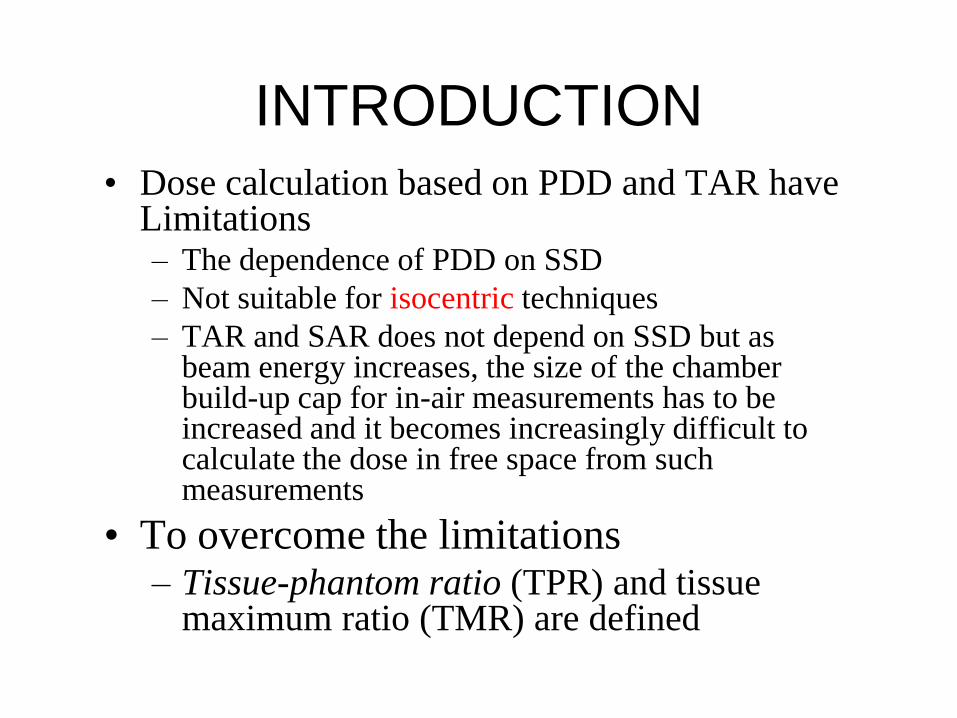
• Dose calculation based on PDD and TAR have Limitations– The dependence of PDD on SSD
– Not suitable for isocentric techniques
– TAR and SAR does not depend on SSD but as beam energy increases, the size of the chamber build-up cap for in-air measurements has to be increased and it becomes increasingly difficult to calculate the dose in free space from such measurements
• To overcome the limitations– Tissue-phantom ratio (TPR) and tissue
maximum ratio (TMR) are defined
INTRODUCTION

• The dose to a point in a medium may be
divided into primary and scattered
components.
• effective primary dose
– the dose due to the primary photons + those
scattered from the collimating system
• The scattered dose has two components
– collimator and phantom components
DOSE CALCULATION PARAMETERS

Collimator Scatter Factor (Sc)
• As the field size is increased,
the output increases because of
the increased collimator scatter
• Sc is commonly called the
output factor
• Defined as ratio of output
in air for a given field to
the output for reference
field

Phantom Scatter Factor (Sp)
• Sp account the change in scatter radiation
originating in the phantom at a reference depth as
the field size is changed.
• Sp is related to the changes in the volume of the
phantom irradiated for a fixed collimator opening
• Sp and Sc,p are defined at the reference depth of Dm
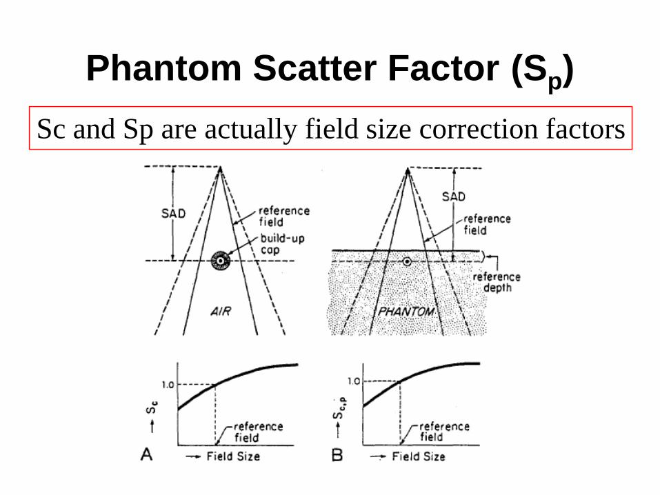
Phantom Scatter Factor (Sp)
Sc and Sp are actually field size correction factors

Tissue-Phantom and Tissue-Maximum Ratios
(Depth Correction Factors)
• The TPR is defined as the ratio
of the dose at a given point in
phantom to the dose at the same
point at a fixed reference depth,
usually 5 cm
• TPR(rd, d) =
D(rd, d) / D(rd, t0)
If t0 = dmax then TPR is called
TMR
• dmax should be chosen for the
smallest field and the largest
SSD.

Properties of TMR
• Independent of the
divergence of the beam
means independent of
SSD
– single table of TMRs
can be used for all SSDs
• Depends only on the
field size at the point
and the depth of the
overlying tissue.

Properties of TMR
• TMR and percent depth dose
f
t0

Scatter-Maximum Ratio
• Designed specifically for the calculation of
scattered dose in a medium

PRACTICAL APPLICATIONS
• a calculation system must be generally
applicable to the clinical practices, with
acceptable accuracy and simplicity for
routine use.

Accelerator Calculations-SSD
• PDD is a suitable quantity for calculations for
SSD setups
• Machines calibration
– deliver 1 cGy / MU at the reference depth t0 , for a
reference field size 10 x 10 cm and a source-to-
calibration point distance of SCD
– Sc is defined at the SAD, Sp relates to the field
irradiating the patient.

Accelerator Calculations-SSD

Accelerator Calculations-SSD

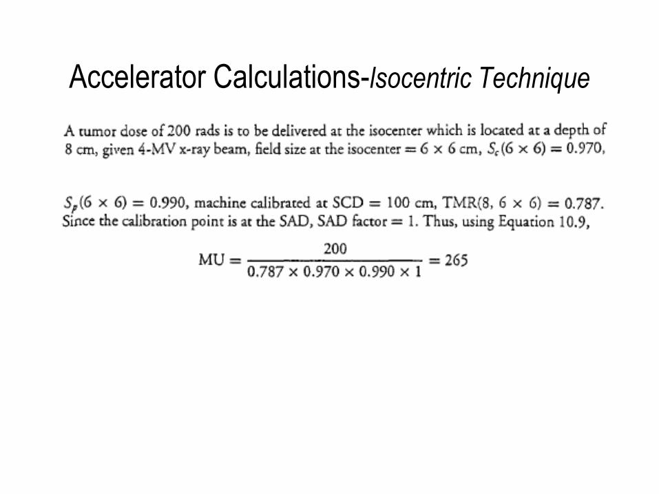
Accelerator Calculations-lsocentric Technique
• Unit calibrated to give 1 cGy / MU at the
reference depth to, calibration distance SCD, and
for the reference field (10 x 10 cm)
Accelerator Calculations-lsocentric Technique
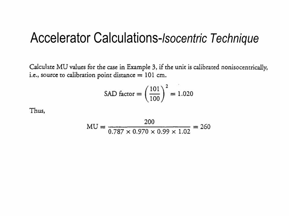
Accelerator Calculations-lsocentric Technique

Accelerator Calculations-lsocentric Technique

Accelerator Calculations- Irregular Fields
• A Clarkson type integration may be performed to
give averaged SMR(d, rd) for the irregular field rd
• Above equation is valid only
for points along the central
axis of am beam that is
normally incident on an
infinite phantom with flat
surface
Where ri is the radius of ith sector and n is the total number of sectors

Accelerator Calculations- Irregular Fields• For off-axis points in a beam with nonuniform primary
dose profile. where Kp is the off-axis ratio
• PDD from TMR
Accelerator Calculations- Irregular Fields
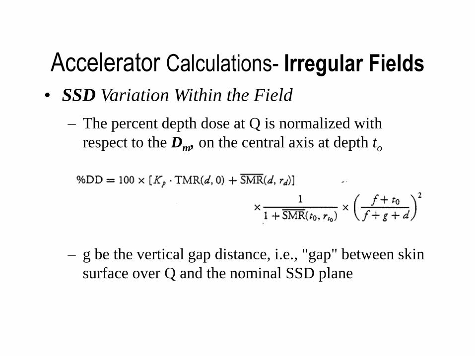
• SSD Variation Within the Field
– g be the vertical gap distance, i.e., "gap" between skin
surface over Q and the nominal SSD plane
– The percent depth dose at Q is normalized with
respect to the Dm, on the central axis at depth to
Accelerator Calculations - Asymmetric Fields
• Jaw moved independently
• Allow asymmetric fields with field centers
positioned away from the true central axis of the
beam
• Sc , will depend on the actual collimator opening
– symmetric field of the same collimator opening as that
of the given asymmetric field
• Sp, can also be assumed to be the same for an
asymmetric field as for a symmetric field of the
same dimension and shape

Accelerator Calculations - Asymmetric Fields
• The primary dose distribution has been shown to vary
with lateral distance from central axis because of the
change in beam quality
• The PDD or TMR distribution along the central ray
of an asymmetric field is not the same as along the
central axis of a symmetric field of the same size and
shape
• the incident primary beam fluence at off-axis points
varies as a function of distance from the central axis,
depending on the flattening filter design

Accelerator Calculations - Asymmetric Fields
• beam flatness within the central 80% of the
maximum field size is specified within ±3% at a 10-
cm depth, ignoring off-axis dose correction in
asymmetric fields will introduce errors of that
magnitude under these conditions

Accelerator Calculations - Asymmetric Fields
• For SSD type
• For isocentric type
– where OARd(x) is the primary off-axis ratio at
depth d

OTHER PRACTICAL METHODS
• Irregular Fields

OTHER PRACTICAL METHODS
• Point Off-Axis– Q is off-axis point where dose is to be calculated and KQ is off axis ratio

OTHER PRACTICAL METHODS
• This off-axis decrease in dose is due to the
reduced scatter at point Q compared with point P

OTHER PRACTICAL METHODS
• Point Outside the Field

OTHER PRACTICAL METHODS
• Point Outside the Field

OTHER PRACTICAL METHODS
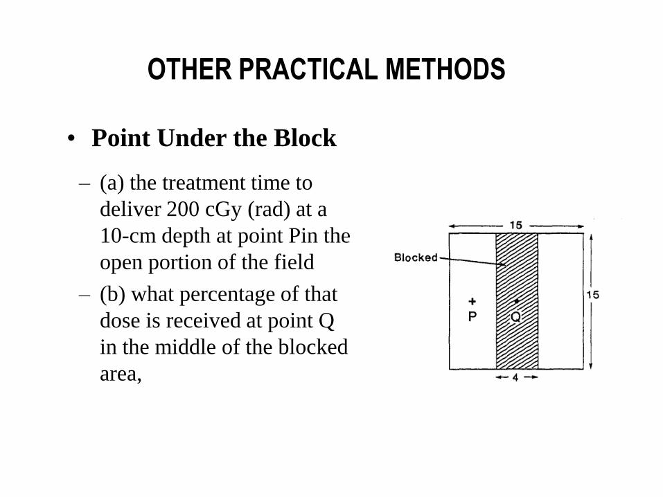
• Point Under the Block
– A patient is treated with a split field of overall size 15 x
15 cm, blocked in the middle to shield a region of size 4
x 15 cm on the surface
– given Co-60 beam, SSD = 80 cm, dose rate free space
for a 15 x 15-cm field at 80.5 cm = 120 rad/min, lead
block thickness = 5 cm with primary beam transmission
of 5%, and shadow tray (or block tray) transmission =
0.97
OTHER PRACTICAL METHODS
• Point Under the Block
– (a) the treatment time to
deliver 200 cGy (rad) at a
10-cm depth at point Pin the
open portion of the field
– (b) what percentage of that
dose is received at point Q
in the middle of the blocked
area,

OTHER PRACTICAL METHODS
• Point Under the Block

OTHER PRACTICAL METHODS
• Point Under the Block