a system for three-dimensional robotic mapping of...
TRANSCRIPT
A System for Three-Dimensional Robotic
Mapping of Underground MinesMichael Montemerlo, Dirk Hahnel, David Ferguson,
Rudolph Triebel, Wolfram Burgard, Scott ThayerWilliam Whittaker, and Sebastian Thrun
Oct 27, 2002CMU-CS-02-185
School of Computer ScienceCarnegie Mellon University
Pittsburgh, PA 15213
This research is sponsored by by DARPA’s MARS Program (Contract number N66001-01-C-6018) and the National Science Foundation (CAREER grant number IIS-9876136 and regulargrant number IIS-9877033), all of which is gratefully acknowledged. The views and conclusionscontained in this document are those of the author and should not be interpreted as necessarilyrepresenting official policies or endorsements, either expressed or implied, of the United StatesGovernment or any of the sponsoring institutions.
Abstract
We describe two robotic systems [6] for acquiring high-resolution volumetricmaps of underground mines. Our systems have been deployed in an operationalcoal mine in Bruceton, Pennsylvania, where they have been used to generateinteractive 3-D maps. Our approach includes a novel sensor head, assembledfrom multiple SICK laser range finders, and a real-time algorithm for scan match-ing that generates accurate volumetric maps. The scan matching algorithm per-forms horizontal and vertical simultaneous localization and mapping (SLAM).Data from the horizontal scans is used to remove artifacts in the vertical scans,and vice versa. The system can construct full 3-D volumetric maps hundreds ofmeters in diameter, even when no odometry information is available.
Keywords: Robot mapping, mine mapping, mobile robotics, probabilisticrobotics
1 Introduction
Throughout the industrialized world, the lack of accurate maps of inactive, un-derground mines poses a serious threat to public safety. According to a recentarticle [1], “Tens of thousands, perhaps even hundreds of thousands, of aban-doned mines exist today in the United States. Not even the U.S. Bureau of Minesknows the exact number, because federal recording of mining claims was not re-quired until 1976.”1 In July of 2002, nine miners were nearly killed in the Que-Creek Mine in Somerset, Pennsylvania when they accidentally drilled into theabondoned Saxmon Mine, releasing millions of gallons of water in the QueCreekmine. This accident highlights the pressing need for accurate maps of abandonedmines.
Hazardous operating conditions and difficult access routes suggest that roboticexploration and mapping of abondoned mines may be necessary. Robotic minemapping has been pursued by various research groups around the world. Corkeand colleagues [3] have built vehicles that can acquire and utilize accurate 2-Dmaps of flat mines. Similarly, Baily [14] reports 2-D mapping results of an un-derground area using advanced mapping techniques. The mine mapping problemis made challenging by the lack of global position information underground. Asa result, mine mapping must be approached as a simultaneous localization andmapping, or SLAM, problem [4, 8, 13, 16]. The robot must construct a map of themine, while estimating its own position at the same time. The SLAM problem isknown to be particularly difficult when the environment possesses loops [5, 15].Unfortunately, mines typically contain a large number of cycles, and we know ofno robotic system that could handle such maps. Moreover, none of the existingrobotic mine mapping systems produce accurate volumetric 3-D maps.
The systems described in this paper are capable of generating volumetric 3-Dmodels of mines. Our first system makes the common (but unrealistic) assump-tion of a flat floor inside the mine. This system has been used to generate accuratevolumetric maps of relatively flat mines. The second, more elaborate system doesnot rely on a flat world assumption. It uses multiple range finders to generate
1See the course page http://www.cs.cmu.edu/afs/cs.cmu.edu/academic/ class/16861-f02/www/for more information.
1
accurate volumetric maps for mines that change elevation. At the core of bothsystems are 2-D laser range finders, which are used for position referencing andfor the recovery of the volumetric structure of a mine. Our initial system usedtwo such sensors, one for each of the two functions described above. To accom-modate uneven terrain, our second system uses four sensors, effectively extendingthe mine mapping capabilities of our first system into a vertical dimension. Wepresent in this paper a new scan matching algorithm that exploits the overlappinglaser range scans, to correct for noise and alignment errors in the data. The result-ing mine maps are highly accurate 3-D models that can be visualized interactivelyby mining staff.
2 The Systems
Figures 1 and 2 show our two volumetric mine mapping systems. Our first proto-type, shown in Figure 1, consists of a modified Pioneer AT robot. It is equippedwith two SICK laser range finders, one pointing forward parallel to the floor, andone pointing upward perpendicular to the robot’s heading direction. In addition,the robot is equipped with two wheel encoders to measure approximate robot mo-tion. The forward-pointing laser scanner is used for simultaneous localizationand mapping (SLAM) in 2-D. Using this data, the robot acquires an accurate 2-Dmap of the environment. The upward-pointing laser is used to reconstruct the 3-Dshape of the walls and the ceiling of the mine, registered in space according toposition estimates gathered from the 2-D map.
The limitations of the robotic system are immediately apparent. First andforemost, the system is confined to flat surfaces, due to its inability to sense orincorporate variations in elevation while performing SLAM. In this way, the sys-tem bears close resemblance to existing work on volumetric mapping of indoorenvironments [11, 7, 9], which principally lacks an extension into the third, verti-cal dimension when performing SLAM. Additionally, the robot platform was notrugged enough to handle the uneven, frequently wet terrain common in mines.Most notably, the robot was not able to cross rail-road tracks used to transport oreinside the mine.
To overcome these limitations, we developed the sensor cart assembly shown
2
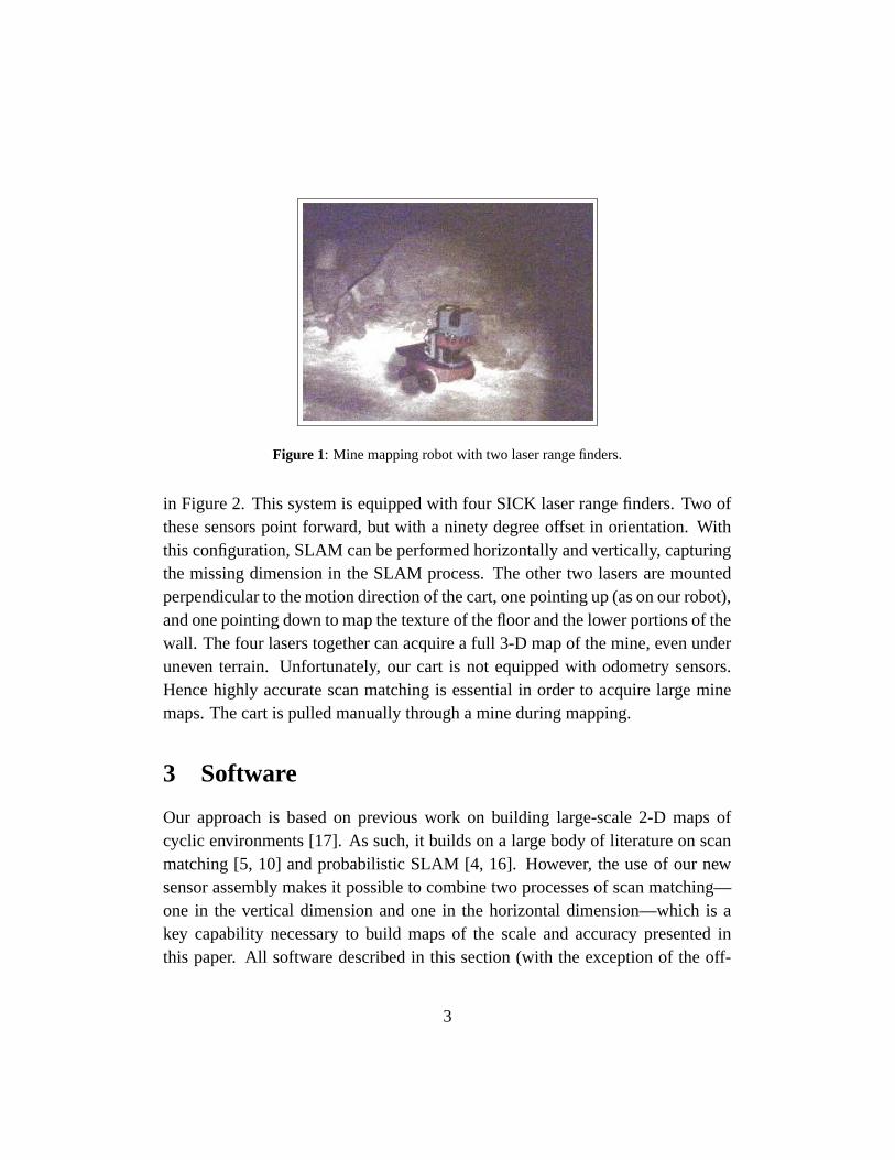
Figure 1: Mine mapping robot with two laser range finders.
in Figure 2. This system is equipped with four SICK laser range finders. Two ofthese sensors point forward, but with a ninety degree offset in orientation. Withthis configuration, SLAM can be performed horizontally and vertically, capturingthe missing dimension in the SLAM process. The other two lasers are mountedperpendicular to the motion direction of the cart, one pointing up (as on our robot),and one pointing down to map the texture of the floor and the lower portions of thewall. The four lasers together can acquire a full 3-D map of the mine, even underuneven terrain. Unfortunately, our cart is not equipped with odometry sensors.Hence highly accurate scan matching is essential in order to acquire large minemaps. The cart is pulled manually through a mine during mapping.
3 Software
Our approach is based on previous work on building large-scale 2-D maps ofcyclic environments [17]. As such, it builds on a large body of literature on scanmatching [5, 10] and probabilistic SLAM [4, 16]. However, the use of our newsensor assembly makes it possible to combine two processes of scan matching—one in the vertical dimension and one in the horizontal dimension—which is akey capability necessary to build maps of the scale and accuracy presented inthis paper. All software described in this section (with the exception of the off-
3
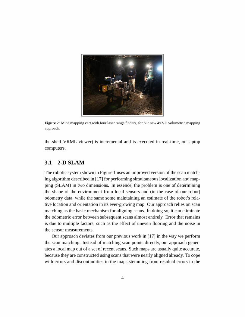
Figure 2: Mine mapping cart with four laser range finders, for our new 4x2-D volumetric mappingapproach.
the-shelf VRML viewer) is incremental and is executed in real-time, on laptopcomputers.
3.1 2-D SLAM
The robotic system shown in Figure 1 uses an improved version of the scan match-ing algorithm described in [17] for performing simultaneous localization and map-ping (SLAM) in two dimensions. In essence, the problem is one of determiningthe shape of the environment from local sensors and (in the case of our robot)odometry data, while the same some maintaining an estimate of the robot’s rela-tive location and orientation in its ever-growing map. Our approach relies on scanmatching as the basic mechanism for aligning scans. In doing so, it can eliminatethe odometric error between subsequent scans almost entirely. Error that remainsis due to multiple factors, such as the effect of uneven flooring and the noise inthe sensor measurements.
Our approach deviates from our previous work in [17] in the way we performthe scan matching. Instead of matching scan points directly, our approach gener-ates a local map out of a set of recent scans. Such maps are usually quite accurate,because they are constructed using scans that were nearly aligned already. To copewith errors and discontinuities in the maps stemming from residual errors in the
4
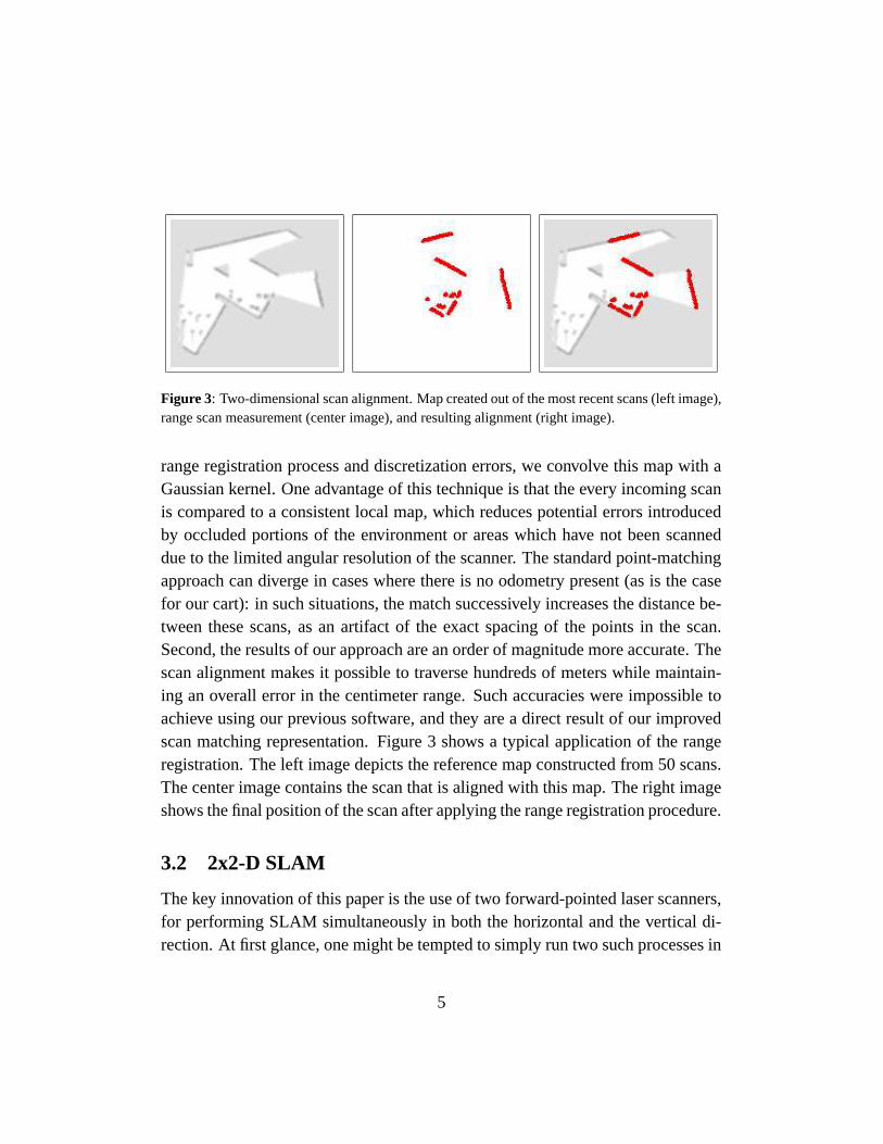
Figure 3: Two-dimensional scan alignment. Map created out of the most recent scans (left image),range scan measurement (center image), and resulting alignment (right image).
range registration process and discretization errors, we convolve this map with aGaussian kernel. One advantage of this technique is that the every incoming scanis compared to a consistent local map, which reduces potential errors introducedby occluded portions of the environment or areas which have not been scanneddue to the limited angular resolution of the scanner. The standard point-matchingapproach can diverge in cases where there is no odometry present (as is the casefor our cart): in such situations, the match successively increases the distance be-tween these scans, as an artifact of the exact spacing of the points in the scan.Second, the results of our approach are an order of magnitude more accurate. Thescan alignment makes it possible to traverse hundreds of meters while maintain-ing an overall error in the centimeter range. Such accuracies were impossible toachieve using our previous software, and they are a direct result of our improvedscan matching representation. Figure 3 shows a typical application of the rangeregistration. The left image depicts the reference map constructed from 50 scans.The center image contains the scan that is aligned with this map. The right imageshows the final position of the scan after applying the range registration procedure.
3.2 2x2-D SLAM
The key innovation of this paper is the use of two forward-pointed laser scanners,for performing SLAM simultaneously in both the horizontal and the vertical di-rection. At first glance, one might be tempted to simply run two such processes in
5

Figure 4: Surface visualization using past scan matching techniques (top), compared to a mineview using our present scan matching process (bottom). In 3-D, the difference of improved scanmatching is much more apparent than in 2-D.
parallel, resulting in accurate 2-D cross-sectional maps of the mine that togetherallow for a recovery of the 3-D structure (under the obvious assumption that over-all, the floor of the mine is not slanted sidewards). However, such a methodologyis prone to fail in real mines.
The reason for such failure lies in the effect that variations in one dimensionhave on the measurements in the other. Consider, for example, a dip in the floorof the mine. This is clearly a vertical feature, and the vertical SLAM processcan easily measure and map such a relief feature. However, as the cart is beingmoved through the mine, its horizontal sensor may see the ground, creating a‘phantom’ obstacle in front of the robot. Phantom obstacles are usually fatal to
6
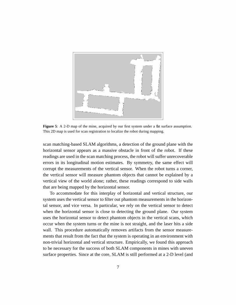
Figure 5: A 2-D map of the mine, acquired by our first system under a flat surface assumption.This 2D map is used for scan registration to localize the robot during mapping.
scan matching-based SLAM algorithms, a detection of the ground plane with thehorizontal sensor appears as a massive obstacle in front of the robot. If thesereadings are used in the scan matching process, the robot will suffer unrecoverableerrors in its longitudinal motion estimates. By symmetry, the same effect willcorrupt the measurements of the vertical sensor. When the robot turns a corner,the vertical sensor will measure phantom objects that cannot be explained by avertical view of the world alone; rather, these readings correspond to side wallsthat are being mapped by the horizontal sensor.
To accommodate for this interplay of horizontal and vertical structure, oursystem uses the vertical sensor to filter out phantom measurements in the horizon-tal sensor, and vice versa. In particular, we rely on the vertical sensor to detectwhen the horizontal sensor is close to detecting the ground plane. Our systemuses the horizontal sensor to detect phantom objects in the vertical scans, whichoccur when the system turns or the mine is not straight, and the laser hits a sidewall. This procedure automatically removes artifacts from the sensor measure-ments that result from the fact that the system is operating in an environment withnon-trivial horizontal and vertical structure. Empirically, we found this approachto be necessary for the success of both SLAM components in mines with unevensurface properties. Since at the core, SLAM is still performed at a 2-D level (and
7
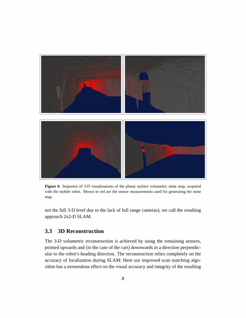
Figure 6: Sequence of 3-D visualizations of the planar surface volumetric mine map, acquiredwith the mobile robot. Shown in red are the sensor measurements used for generating the minemap.
not the full 3-D level due to the lack of full range cameras), we call the resultingapproach 2x2-D SLAM.
3.3 3D Reconstruction
The 3-D volumetric reconstruction is achieved by using the remaining sensors,pointed upwards and (in the case of the cart) downwards in a direction perpendic-ular to the robot’s heading direction. The reconstruction relies completely on theaccuracy of localization during SLAM: Here our improved scan matching algo-rithm has a tremendous effect on the visual accuracy and integrity of the resulting
8
maps when compared to our previous work. In particular, Figure 4 shows a cross-section of the raw 3-D data obtained by straightforward interpolation betweenadjacent sensor scans, and compares it with previous results obtained with ourolder scan matching approach [17]. This improved visual accuracy is partially afunction of our improved scan matching.
In addition to that, we employ a local smoothing operator that further smoothsthe surface. Similar smoothing techniques were applied in [17].
4 Results
All results have been obtained in two different setions of an experimental coalmine in Bruceton, Pennsylvania. This mine is operated as a research mine by theU.S. Bureau of Mines, enabling us to operate robotic equipment without the needfor explosion-proof certification. A partial map of the mine is shown in Figure 7(bottom panel).
Figure 5 shows the result of 2-D mapping using our robotic system, of a smallfraction of the mine with a sufficiently flat floor. This section of the mine had aconcrete floor, facilitating its use as a research mine. However, concrete flooringis clearly unrepresentative of existing, and abandoned mines. As argued above,the flatness of the floor is essential for the success of our initial robotic system,which only performs SLAM in the horizontal direction.
3-D volumetric maps obtained using this system are shown in Figure 6. Thisvisualization shows only the upper fraction of the mine. The map is incompletedue to the use of a single sensor for volumetric mapping on our robot. Neverthe-less, these results illustrate that under idealized conditions, our initial system isindeed capable of acquiring accurate mine maps. However, our system failed inmore realistic setting, where uneven floors and other artifacts (tracks, mud, water)made it impossible to acquire accurate maps.
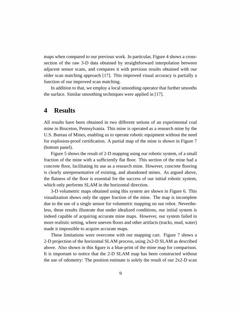
These limitations were overcome with our mapping cart. Figure 7 shows a2-D projection of the horizontal SLAM process, using 2x2-D SLAM as describedabove. Also shown in this figure is a blue-print of the mine map for comparison.It is important to notice that the 2-D SLAM map has been constructed withoutthe use of odometry: The position estimate is solely the result of our 2x2-D scan
9
Figure 7: 2-D projection of the 3-D volumetric mine map, acquired by our mine mapping cartwithout odometry. A comparison with the manually constructed 2-D map illustrate the accuracyof our automatically acquired mine map.
matching approach. The largest loop in this map is several hundred meters incircumference, making this one of the largest loops in a confined environment evermapped by probabilistic scan matching techniques. The lack of completeness ofthe map is due to closed doors and other massive obstacles that rendered many of
10
the corridors in the mine inaccessible.The resulting 3-D map is visualized in Figure 8. This map is represented in
VRML format, allowing for an interactive visualization and exploration of themapped mine. As these screen shots illustrate, the resulting map captures the full3-D structure of the parts of the mines accessible to the cart. The resulting mapcaptures both the horizontal and the vertical structure of the mine. The visualiza-tion tool enables mine personnel to inspect the mine from views that cannot bephysically attained, such as the outside visualization shown in the bottom panelof that figure.
5 Conclusion
We have presented two implemented systems for acquiring volumetric maps ofmines. Our first system relied on a robotic platform, equipped with two laserscanners. Our second, more versatile system used four range sensors, and wasmounted on a cart. To achieve accurate mine mapping, we have developed a newscan matching algorithm that fuses information from a horizontal and a verticalsensor while performing SLAM in 2D. The volumetric map is then reconstructedfrom measurements acquired by additional laser sensors. As the results in thispaper illustrate, our new scan matching approach enables us to obtain consistentvolumetric maps of mines with significant vertical and horizontal structure. Thefact that our final results were obtained in the absence of any odometry data illus-trates the robustness of our approach.
We believe that the volumetric mine maps are unprecedented in the roboticsliterature in their scale, resolution, and by virtue of the fact that they are volumet-ric, and not just two-dimensional. The 2x2-D system is presently been extended toa rugged ATRV platform capable of traversing the type terrain found in mines, ina self-propelled mode. We anticipate that this will provide us with an automatedrobotic system for acquiring large maps of mines. We also believe that existingtechniques for mobile robot exploration [2, 12, 18] can be adapted for the purposeof autonomously exploring mines.
11

Figure 8: Sequence of 3-D visualizations of the full 3-D volumetric mine map. This map hasbeen built using our new sensor cart and using our 2x2-D scan matching algorithm, without anyodometry information.
12
Acknowledgment
This research was motivated and supported by an ongoing mine mapping courseoffered by Red Whittaker and Scott Thayer, whose encouragement is greatly ac-knowledged. The research has been sponsored by DARPA’s MARS Program(contract N66001-01-C-6018 and contract NBCH1020014), which is gratefullyacknowledged. Special thanks to the Bruceton Research Center for access to theBruceton experimental mine.
References
[1] J.J. Belwood and R.J. Waugh. Bats and mines: Abandoned does not alwaysmean empty. Bats, 9(3), 1991.
[2] W. Burgard, D. Fox, M. Moors, R. Simmons, and S. Thrun. Collaborativemulti-robot exploration. In Proceedings of the IEEE International Confer-ence on Robotics and Automation (ICRA), San Francisco, CA, 2000. IEEE.
[3] P. Corke, J. Cunningham, D. Dekker, , and H. Durrant-Whyte. Autonomousunderground vehicles. In Proceedings of the CMTE Mining Technology Con-ference, pages 16–22, Perth, Australia, September 1996.
[4] G. Dissanayake, H. Durrant-Whyte, and T. Bailey. A computationally ef-ficient solution to the simultaneous localisation and map building (SLAM)problem. Working notes of ICRA’2000 Workshop W4: Mobile Robot Navi-gation and Mapping, April 2000.
[5] J.-S. Gutmann and K. Konolige. Incremental mapping of large cyclic envi-ronments. In Proceedings of the IEEE International Symposium on Compu-tational Intelligence in Robotics and Automation (CIRA), 2000.
[6] D. Hahnel, M. Montemerlo, D. Ferguson, R. Triebel, W. Burgard, andS. Thrun. A system for volumetric robotic mapping of underground mines.Submitted for publication, 2002.
13
[7] L. Iocchi, K. Konolige, and M. Bajracharya. Visually realistic mapping ofa planar environment with stereo. In Proceesings of the 2000 InternationalSymposium on Experimental Robotics, Waikiki, Hawaii, 2000.
[8] J. Leonard, J.D. Tardos, S. Thrun, and H. Choset, editors. Workshop Notesof the ICRA Workshop on Concurrent Mapping and Localization for Au-tonomous Mobile Robots (W4). ICRA Conference, Washington, DC, 2002.
[9] Y. Liu, R. Emery, D. Chakrabarti, W. Burgard, and S. Thrun. Using EM tolearn 3D models with mobile robots. In Proceedings of the InternationalConference on Machine Learning (ICML), 2001.
[10] F. Lu and E. Milios. Globally consistent range scan alignment for environ-ment mapping. Autonomous Robots, 4:333–349, 1997.
[11] H.P. Moravec and M.C. Martin. Robot navigation by 3D spatial evidencegrids. Mobile Robot Laboratory, Robotics Institute, Carnegie Mellon Uni-versity, 1994.
[12] R. Simmons, D. Apfelbaum, W. Burgard, M. Fox, D. an Moors, S. Thrun,and H. Younes. Coordination for multi-robot exploration and mapping.In Proceedings of the AAAI National Conference on Artificial Intelligence,Austin, TX, 2000. AAAI.
[13] R. Smith, M. Self, and P. Cheeseman. Estimating uncertain spatial relation-ships in robotics. In I.J. Cox and G.T. Wilfong, editors, Autonomous RobotVehicles, pages 167–193. Springer-Verlag, 1990.
[14] Bailey T. Mobile Robot Localisation and Mapping in Extensive OutdoorEnvironments. PhD thesis, University of Sydney, Sydney, NSW, Australia,2002.
[15] S. Thrun. A probabilistic online mapping algorithm for teams of mobilerobots. International Journal of Robotics Research, 20(5):335–363, 2001.
[16] S. Thrun. Robotic mapping: A survey. In G. Lakemeyer and B. Nebel, ed-itors, Exploring Artificial Intelligence in the New Millenium. Morgan Kauf-mann, 2002. to appear.
14
[17] S. Thrun, W. Burgard, and D. Fox. A real-time algorithm for mobile robotmapping with applications to multi-robot and 3D mapping. In Proceedingsof the IEEE International Conference on Robotics and Automation (ICRA),San Francisco, CA, 2000. IEEE.
[18] B. Yamauchi, P. Langley, A.C. Schultz, J. Grefenstette, and W. Adams. Mag-ellan: An integrated adaptive architecture for mobile robots. Technical Re-port 98-2, Institute for the Study of Learning and Expertise (ISLE), PaloAlto, CA, May 1998.
15