a sysml representation of the wireless factory work-cell
TRANSCRIPT

Noname manuscript No.(will be inserted by the editor)
A SysML Representation of the Wireless Factory Work-cellEnabling real-time observation and control by modeling significant architecture,components, and information flows
Richard Candell, Mohamed Kashef, Yongkang Liu, and Sebti Foufou
Received: date / Accepted: date
Abstract A fourth industrial revolution, occurring in globalmanufacturing, provides a vision of future manufacturingsystems that incorporate highly dynamic physical systems,robust and responsive communications systems, and com-puting paradigms to maximize efficiency, enable mobility,and realize the promises of the digital factory. Wireless tech-nology is a key enabler of that vision. A comprehensivegraphical model is developed for a generic wireless factorywork-cell which employs the Systems Modeling Language(SysML), a standardized and semantically rich modeling lan-guage, to link the physical and network domains in such acyber-physical system (CPS). The proposed model identi-fies the structural primitives, interfaces, and behaviors of thehighly-connected factory work-cell in which wireless tech-nology is used for significant data flows involved in controlalgorithms. The model includes the parametric definitions toencapsulate information loss, delay, and mutation associatedwith the wireless network, and it identifies pertinent wirelessinformation flows.
Keywords industrial wireless, factory communications,networked control systems, manufacturing, cyber-physicalsystems, SysML
1 Introduction
The fourth industrial revolution promises unparalleled pro-ductivity and capability advances in manufacturing. To sup-port the manufacturing industry in this conversion, various
Richard Candell, Mohamed Kashef, and Yongkang LiuNational Institute of Standards and Technology100 Bureau Drive M/S 8230 Tel.: +001-301-975-2000E-mail: {richard.candell,mohamed.kashef,yongkang.liu}@nist.gov
Sebti FoufouUniversity of Burgundy, Dijon, [email protected]
programs have been established in several countries suchas Smart Manufacturing in the U.S. [6] and Industry 4.0in Europe [35, 38]. Propelled by economic pressure towardgreater efficiency, factory agility, and product customiza-tion, future factories will have the technological ability toadapt to customer demands quickly, modify manufacturingprocesses automatically based on quality feedback, and fab-ricate products with a reduced environmental impact. Tech-nological advances required for smart manufacturing to besuccessful include collaborative and mobile robotics [29],distributed machine autonomy based on artificial intelligence[39], improved process observability [59], and a high de-gree of interconnectivity among automation resources [32].Work-cells are self-contained units of operation within a fac-tory [14, 22, 45]. These work-cells are composed of vari-ous machines, conveyors, motors, edge devices, and robots.Robots will work together and with people to accomplishcomplex tasks or to tending to other machines within thework-cell. Robots will have the ability to roam between work-cells within a factory, learn their roles quickly, become awareof edge devices, and communicate with other actors withinthe work-cell to accomplish their goals. Efficient communi-cations between robots and the other players in the work-cellare essential to the fulfillment of the robot-related tasks.
Current manufacturing architectures use wired connec-tions through field-bus and industrial Ethernet protocols forsensing and real-time control [51, 64]. Indeed, through ad-vances in time-sensitive networking, many of the promisesof smart manufacturing are being realized; however, the truegoals of smart manufacturing require a large deploymentof sensing and actuation devices and mobile, perhaps au-tonomous, robotics actors [32]. The use of wires precludesmobility and makes deployment of edge devices more ex-pensive as each requires power, cables, and conduit for com-munication. By adopting wireless for both sensing and con-trol of machines within the work-cell, a lower-cost, unteth-

2 Richard Candell, Mohamed Kashef, Yongkang Liu, and Sebti Foufou
ered operation is achievable1. Once wireless is adopted asthe primary mode of communication, questions arise as tothe required latency, reliability, and scale of the wireless net-work especially when the network is used for the control ofmachines and the assurance of safety [32].
The work presented here addresses the present need fora comprehensive architectural model of the factory work-cell in which wireless is a preferred mechanism for carryinginformation within the work-cell. We begin with an archi-tectural analysis of the future collaborative work-cell thatincludes edge devices, robots, vision systems, and supervi-sory controllers. Our architectural analysis includes struc-tural components, information flows, and parametric elementsof the work-cell. We identify factors that limit reliability, la-tency, and scalability of the wireless network, and we con-clude with a discussion of significant information flows. Sig-nificant information flows are defined as operationally criti-cal or safety-related. Our contributions are:
? First, we develop a comprehensive and extensible archi-tectural model using the Systems Modeling Language(SysML) that provides primitives for describing the phys-ical and networking components of a work-cell with para-metric constraints2;
? Second, we provide a framework for analyzing cross-domain interactions of complex wireless work-cell de-ployments; and
? Third, significant information flows are identified, anno-tated with rate constraints.
The remainder of this paper is organized as follows: InSection 2, previous related work is discussed and our moti-vation for constructing a model is presented. A brief intro-duction to systems modeling is presented in Section 3 andprovides a primer on the SysML language. The conceptualarchitecture of the model providing a concept-of-usage isproposed in Section 4, followed by a detailed exposition ofeach package in Section 5. Then, in Section 6, significantinformation flows are discussed through introducing a casestudy. Section 7 concludes the paper and identifies opportu-nities for future research.
2 Related Work
Current modeling work on factory work-cells is mainly aimedat defining and characterizing the subsystems, such as hu-man staff, robots, and machine tools, in individual applica-tions. By following blueprints (schematics) of production
1 The power for untethered operation can be achieved through theuse of rechargeable batteries to power the untethered machine or robotfor enough operating period.
2 We make the model publicly available for download. A valid li-cense of MagicDraw 18.5 is required to use the model. A web-basedreport of the model is provided for read-only access.
tasks, the work flow can be divided into separate assign-ments which are distributed by a task dispatch system to in-dividual machines [36]. Analytical models are thus obtainedfor performance analysis in work-cells. As an example, amathematical model for real-time performance analysis ofa gantry work-cell with robots is established with the tim-ing and the randomness of tasks and disruptions are cap-tured [53]. In [52], the same model is used to investigate thesystem natural properties such the system cycle and waitingtimes and to identify bottlenecks through studying the sen-sitivity of each machine. Similarly, the steady state analysisfor production lines with uncertainties is performed throughvarious decomposition methods [16, 28, 66]. In [16], a de-composition method is presented for the analysis of contin-uous flow lines. The presented model is used to analyze flowlines with single and multiple failure mode machines andmachines subject to aging and having up and down times.In [66], a model to evaluate the performance of transfer lineswith unreliable machines and finite transfer-delay buffers ispresented. A decomposition method is introduced to modelthe transfer line, using the general-exponential distributionsinstead of the exponential distributions to approximate therepair time distributions of the fictitious machines. In [28],the authors present a model for evaluating the productionrate and distribution of inventory of a closed-loop manufac-turing system with unreliable machines and finite buffers.The model accounts for the different sets of machines thatcould cause blockage or starvation to other machines. In[13, 40], the performance analysis modeling for serial pro-duction lines with disruptions is explored by studying theimpact of each individual downtime event in terms of per-manent production loss and financial cost. These analyticalmodels generally work well for simple systems with smallnumber of components or few interactions between variousequipment. Also, the analytical models can be used to ab-stract industrial systems to understand various performancetrends without studying various details. As a result, we in-troduce a comprehensive model that include network andproduction impacts on the industrial work-cell.
Furthermore, the reconfigurable work-cell architectureis widely considered for automated manufacturing. The mainadvantage of reconfigurable work-cells lies in the flexibil-ity of reconfiguration of work-cell components to adapt tovarying production requirements where the assembly of thework cell is optimized for each specific task [14]. In thework-cell that hosts robots, robots are installed therein toallow for autonomous configuration within their workspace[22,26,47]. Approaches and performance criteria for recon-figurable robotic systems have recent developments in con-trol architectures to achieve various levels of reconfigurabil-ity [25]. The National Institute of Standards and Technol-ogy (NIST) has defined a Network of Things (NoT) modelwhich can depict the structure of work-cells by a group of

A SysML Representation of the Wireless Factory Work-cell 3
NoT building blocks and model the behaviors of individ-ual components in a work-cell [62]. The NIST NoT modelis focused primarily on sensor networks and the collectionof data. Actuation is cursorily noted, and, as such, cross-domain interactions between the physical system and thenetwork are not addressed. Several other robotic work-cellarchitectures are discussed in the literature. In [49], a ref-erence model for a control system functional architectureapplied to open architecture robot controllers is presented.In [12], a methodology to develop self-adaptive factory au-tomation solutions is illustrated, using a novel modular sim-ulation based method. With the increase in complexity andreconfigurability of work-cells, studying various productioncriteria and networks impacts requires introducing new mod-els to capture these interactions and to be abstract enoughto model different configurations and scenarios of industrialwork-cells.
In a work-cell model, data flows are used to capture thetrajectory of system information exchange between work-cell components and identify their roles in specific opera-tions [49]. For example, safety-related operations employthe vision system and various proximity sensors that gen-erate proximity data and transmit them to the safety man-ager to define safety zones in an automotive assembly work-cell [46]. In another example, data flows are enabled in awork-cell to capture human operator gestures from embed-ded cameras in human-robot collaborations [61]. These ges-tures can be later regenerated in simulators based on thetransmitted position data from the field to optimize work-cell safety operations [19]. Currently, most of the work-cellinformation in these scenarios are transmitted by wired net-works. Wireless networks have gained increasing interests toenable data flows in the highly connected work-cells. Wire-less standard bodies have proposed their network referencemodels in factory environments which include the work-cellcases in the data-centric architecture [1, 2]. In these models,individual work-cells are treated as a subnetwork of field in-struments attached with data aggregations that manage net-work connections and transfer data traffic to edge and cloudservers in various applications. Wireless connections are fea-tured with flexible network topology to agree with a varietyof transmission needs, especially in reconfigurable work-cells. Meanwhile, data traffic flows are characterized by se-lect performance metrics, such as transmission latency andlink reliability, to categorize industrial use cases [2].
Current modeling efforts set the boundaries of their sys-tems of study at the edge devices without further discussionson the impact of wireless performance on the operations ofindustrial systems. For example, the abstracted disruptionsin [13, 40] that cause plant downtimes may include wire-less network impacts which are not yet treated distinguish-ably with specific characteristics of wireless networks. Asindicated by the earlier empirical studies [41], such phys-
ical systems may have different responses to network per-formance which will vary with the operational configura-tion such as the served “application” and the deployed con-trol algorithms. In this paper, we incorporate the features ofwireless communications networks into the modeling archi-tecture of physical work-cells such that cross-domain inter-actions may be studied. Prior to introducing the model forwireless incorporation, we first provide the reader an intro-duction to SysML in the following section.
3 Systems Modeling Using SysML
The goal of modeling a system is the capture of knowledgeof a process in a simplified way [55]. A secondary goal ofa system model is to provide a level of abstraction that mayallow for the discovery of new knowledge such as how twosystems will interact. There are multiple ways of design-ing and presenting system models. Well-behaved systemscan be represented by a system of equations using mathe-matical tools [37]. Such models provide excellent constraintdefinition, but lack the semantics to describe architectureand detailed information flow. Moreover, by deploying func-tional block diagrams, we are able to capture major func-tional components and flow of information or material. Asshown in Fig. 1, a physical process interacts with a controlsystem through a wireless network. Measured values, Y ,from sensors flow to the controller through a wireless net-work and arrive at the controller delayed and modified, Y .Similarly, commands, U , flows from the controller to the ac-tuators through the wireless network. Such diagrams may beused to model feedback control systems in which the origi-nation and routing of information are immaterial for study.However, the architecture and interfaces remain at a veryhigh level of abstraction making analysis difficult. In suchcases, delay and loss using such tools are often modeledstochastically. Using architectural diagrams helps identifycomponents, interfaces, and information flow. For factorysystems, architectural block diagrams are often manifestedas schematics. However, such diagrams have their own lim-its in industrial practices. On one hand, they lack the seman-tics necessary to describe the constraints that formal equa-tions and functional block diagrams offer. Meanwhile, theyalso lack the capability of capturing behaviors or complexinteractions between the physical system and the informa-tion infrastructure such as a wireless network.
An alternative to schematic diagrams is SysML [48].SysML is a general purpose modeling language that is oftenused for model-based systems engineering (MBSE) prac-tice within industrial systems [31]. SysML provides struc-tural, behavioral, and parametric semantics for the analysisof complex systems. For examples, systems analysis usingSysML enables capturing and communicating system re-quirements and design which include hardware, software,

4 Richard Candell, Mohamed Kashef, Yongkang Liu, and Sebti Foufou
Fig. 1 Functional block diagram of a cyber-physical system in which aphysical process and an automation system interact through a wirelessnetwork.
firmware, information flows, and processes with graphicalnotations. Within the factory automation industry, engineersare adopting SysML in the form of MBSE to develop real-izable operational models of the factory and data flow pro-cesses. MBSE models address verification of design throughexecutable simulations depending on the modeling tool. TheSysML specification is defined in [48]. In SysML, the basicsemantic constructs of the language are Packages, Blocks,Ports, Interfaces, and Constraints, in addition to the con-structs provided by the Unified Modeling Language (UML).Packages are logical grouping of model elements. Packagerelationships are captured using the package diagram (PKG).Relationships of these constructs are captured in the blockdefinition diagram (BDD). The internal composition and con-nectivity of parts are captured in the internal block diagram(IBD). SysML includes other types of diagrams and seman-tic constructs that are not required for this analysis and arenot explained here. The SysML model is comprehensive;however, the size and number of diagrams within the modelare too extensive to include within this paper. Therefore, thereader is encouraged to explore the SysML model definedin [9]. A useful primer on SysML may be found in [24].
Examples of the use cases and methodologies of usingdifferent graphical models for the analysis of manufactur-ing systems are explored in [3,34,42,43]. In [58], SysML isused to capture both composition and behavior of an additivemanufacturing work-cell. A survey of applying graphicalmodeling languages in capturing information flows within aproduct service system which may be applied to manufactur-ing enterprises [20]. Our approach compliments these pre-vious examples by combining the operational and wirelessinformation transport systems together in a single model,thereby facilitating a single model that may be used for sim-ulation and other systems engineering analyses.
While various architectures for the work-cell exist as ex-emplified in the literature, a common language and frame-work for communicating architecture and information flowhas not been established for cross-domain interactions be-tween the manufacturing system and its supporting commu-nication networks. SysML contains the semantics for suchengineering capture and provides an industry accepted lan-guage for communicating composition, interfaces, and in-formation flow. Moreover, SysML provides the semantics
Fig. 2 SysML package diagram showing the logical containment ofthe factory work-cell structural elements.
for assigning properties to any model element such that thoseproperties are made available for analysis using other toolssuch as Protege [60] and the Web Ontology Language (OWL)[63]. It is important to understand that while SysML pro-vides semantics for a formal capture of architecture, infor-mation flow, and parametric constraints, it may also be usedfor a higher-degree of abstraction provided by the functionalblock diagrams.
4 Conceptual Representation
The remainder of this work describes a reusable model forrepresenting a comprehensive wireless factory work-cell us-ing the semantic constructs of SysML. We now follow withan exposition of our model beginning with the conceptualmodel followed by a detailed description of each componentwithin the model. When discussing the model, the SysMLterm, block, is omitted for the sake of brevity where themeaning is clear.
4.1 Packages
The factory work-cell is decomposed into one general andnine major structural packages as shown in Fig. 2. Pack-ages include major logical groupings of structure within themodel. These packages are enumerated in the following para-graphs.

A SysML Representation of the Wireless Factory Work-cell 5
4.1.1 General
A set of reusable structural elements that is used for concep-tual modeling or extended to produce more complex modelelements. Each of the sub-packages within the General pack-age extends basic features. The sub-packages within Generalinclude time and constraints for data, electro-magnetics, andmotion.
4.1.2 Network
Describes the components, blocks, interfaces, and limitingfactors of the industrial wireless network (IWN). The IWNis modeled as the radio channel and the services providedby the network. Limiting factors are modeled as parametricequations associated with the radio channel and the services.
4.1.3 Application
This package contains the model elements describing a com-ponent of behavioral functionality typically implemented withinsoftware or firmware but could be implemented in hardware.It describes the features and constraints of factory operationsuch as the logic of a supervisory controller or the feedbackcontroller of a robot arm. The Application sets the perfor-mance requirements of the wireless network, i.e., the factorynetwork performance requirements are derived from the re-quirements of the applications deployed to a work-cell.
4.1.4 Devices
Describes the types of devices found within the factory work-cell to include any device that interacts with the environmentsuch as wired and wireless input-output (IO) devices includ-ing sensors and actuators.
4.1.5 Robotics
Describes the computational and communicative componentsof robot control including sensing, actuation, and command.Description of the robot itself is inconsequential to commu-nication and therefore not included in the model.
4.1.6 PLC
Describes the supervisory control components commonlyhandled by one or more programmable logic controller (PLC)components. This package includes the elements responsi-ble for coordination of actors and handling of most input-output.
4.1.7 Safety
Describes the allocation of safety qualities typically includedin the supervisory controller. The Safety package includesdevices, monitoring, and actuation of the safety behaviorswithin the factory work-cell.
4.1.8 Vision
Describes the allocation of features to optical monitoringand tracking which are typical to the collaborative roboticwork-cell.
4.1.9 Spectrum Monitoring System (SMS)
Describes the qualities and interfaces of a factory spectrummonitoring system projected into the factory work-cell. TheSMS includes monitoring nodes and agents localized to thework-cell and connected to the automation system for real-time adaptation to changing multi-path and interference.
4.1.10 Human
Describes the features associated with human beings such ashuman motion, tasks, and carried equipment such as portablecomputing and communication devices.
Several examples of how to use the model are providedwithin the model [9]. Examples include: a robotic force-torque leader-follower, a robotic force-torque limiter, a col-lision avoidance, and a robotic pick and place work-cell. Theparametric constraints are provided as examples and are in-tended to be used for communication to project stakeholdersor replaced with executable computer code such as MAT-LAB or Python scripts, thereby making the model useful forsimulation depending on the modeling tool selected.
4.2 Conceptual Architecture
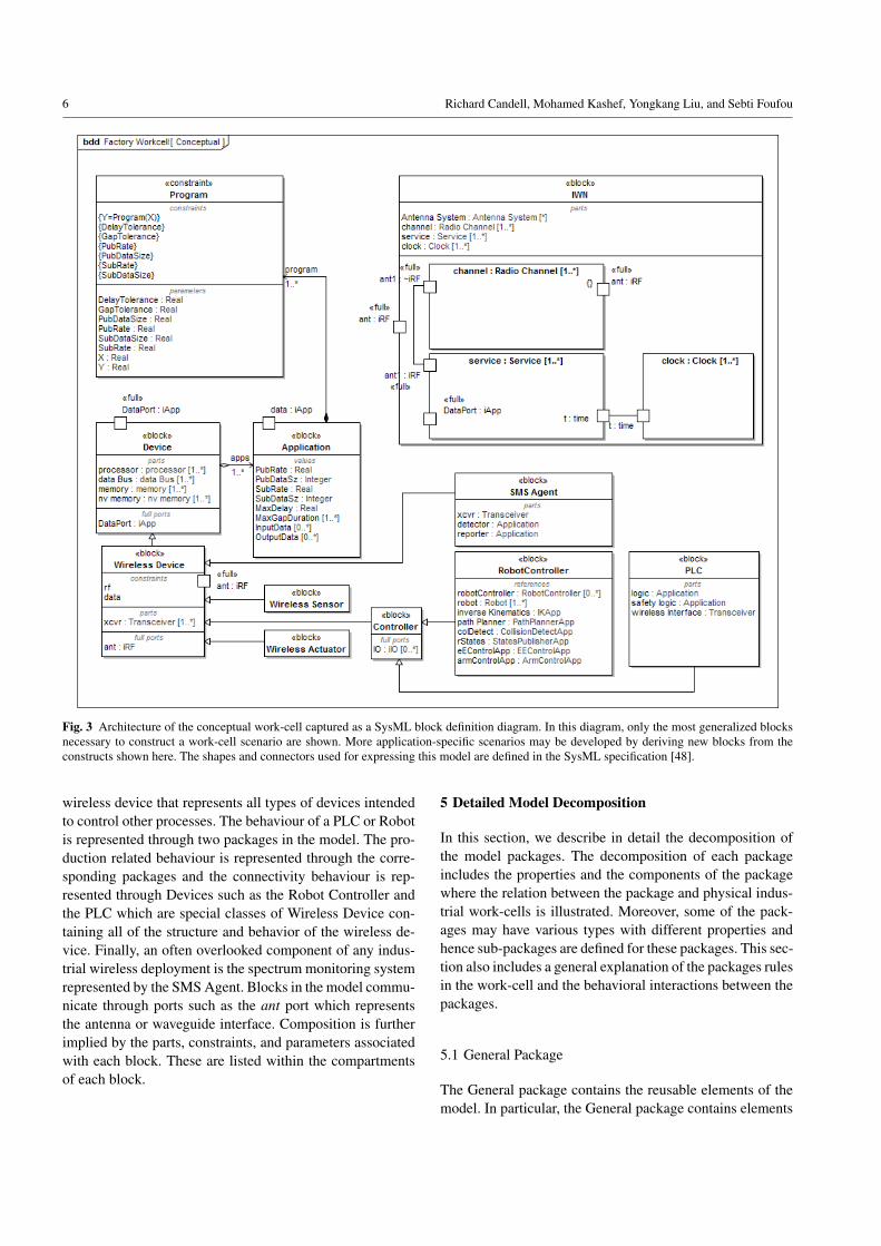
The conceptual architecture of the wireless work-cell modelis depicted in Fig. 3. All the packages are included in this ar-chitecture, and the connections and relations between blocksare defined using the SysML semantics. This figure serves toorient the reader during the presentation of detailed modeldecomposition in Section 5. The work-cell model is com-posed of at least one Industrial Wireless Network (IWN)block and at least one Device block. More IWN blocks areused when multiple wireless networks coexist within the in-dustrial work-cell. Applications are associated with Devicesand performance constraints are applied to Applications. Inthis model, the Wireless Device is a subclass of Device, andthe Controller is a further derivation of the wireless device.Moreover, the Controller is an abstract specialization of a
6 Richard Candell, Mohamed Kashef, Yongkang Liu, and Sebti Foufou
Fig. 3 Architecture of the conceptual work-cell captured as a SysML block definition diagram. In this diagram, only the most generalized blocksnecessary to construct a work-cell scenario are shown. More application-specific scenarios may be developed by deriving new blocks from theconstructs shown here. The shapes and connectors used for expressing this model are defined in the SysML specification [48].
wireless device that represents all types of devices intendedto control other processes. The behaviour of a PLC or Robotis represented through two packages in the model. The pro-duction related behaviour is represented through the corre-sponding packages and the connectivity behaviour is rep-resented through Devices such as the Robot Controller andthe PLC which are special classes of Wireless Device con-taining all of the structure and behavior of the wireless de-vice. Finally, an often overlooked component of any indus-trial wireless deployment is the spectrum monitoring systemrepresented by the SMS Agent. Blocks in the model commu-nicate through ports such as the ant port which representsthe antenna or waveguide interface. Composition is furtherimplied by the parts, constraints, and parameters associatedwith each block. These are listed within the compartmentsof each block.
5 Detailed Model Decomposition
In this section, we describe in detail the decomposition ofthe model packages. The decomposition of each packageincludes the properties and the components of the packagewhere the relation between the package and physical indus-trial work-cells is illustrated. Moreover, some of the pack-ages may have various types with different properties andhence sub-packages are defined for these packages. This sec-tion also includes a general explanation of the packages rulesin the work-cell and the behavioral interactions between thepackages.
5.1 General Package
The General package contains the reusable elements of themodel. In particular, the General package contains elements

A SysML Representation of the Wireless Factory Work-cell 7
that are not particular to any one work-cell component butcan be reused or applied across several. The concepts oftime, clocks, and synchronization are included within Gen-eral. Moreover, several types of constraints are defined.
5.1.1 Time
Time is an important construct within communication sys-tems as well as industrial control systems. Time is realizedas a set of one or more clocks. A work-cell will contain oneto several clocks typically embedded within each device toallow those devices to synchronize to a common clock. Thelocal clocks within the work-cell devices will synchronize toa master reference clock and usually one with a high degreeof precision, accuracy, and stability. The degree to whichthe local clocks synchronize to the master will depend onthe requirements of the applications that the local clocksserve. Clock synchronization can be costly in power, size,and monetary cost of the devices, but it may be necessarydepending on the applications using a clock. Clock perfor-mance is a key driver of size and power consumption, andsynchronization of clocks across a wireless network can bea challenge and is a highly studied field [27, 44]. Moreover,the Time package includes a constraint, Clock Performance,to represent the production of time and synchronization witha master clock.
5.1.2 Constraints
Constraints provide limitations on the performance of an el-ement within the model. Within General, several constraintsare defined which may be applied to any block within themodel. These constraints include motion constraints, radiochannel constraints, and networking constraints as shown inFig. 4a-4c.
Motion Constraints When applied, these constraints providethe bounds of dynamical performance. For example, motionconstraints determine the positions, velocities, and acceler-ations on a rigid body. The force vector equations (1) arethe general governing dynamic laws of motion as forces ona vector of joints as exerted by the end-effector or set ofend-effectors on the environment. The equations constrainthe robot to operate according to the laws of physics, wherethe joint-space inertia matrix, H , is an n × n symmetric,positive-definite matrix, and q, q, and q are vectors of po-sition, velocity, and acceleration, respectively. The variablefext is the six degrees of freedom (DOF) force acting on theend-effector, and c is the joint-space bias force required toproduce a zero sum force on the end-effector [21].
Γ = H(q)q + c(q, q, fext) (1)
where Γ is the vector of forces exerted by the end-effectors.
(a) Motion Constraints
(b) Radio Channel Constraints
(c) Networking Service Constraints
Fig. 4 Generalized network constraints consisting of rigid body mo-tion (a), the radio channel (b) and the network services (c).
This system of equations is controlled using a combi-nation of digital feed-forward and feedback compensationin which the communication mechanism of the robot statesdirectly impacts the controller’s effectiveness. Joint controlvia a wireless network connection is typically avoided; how-ever, monitoring of the linear and angular forces representedby fext as sensed by a 6-DOF force-torque (FT) wirelesssensor can be advantageous for many industrial applications.

8 Richard Candell, Mohamed Kashef, Yongkang Liu, and Sebti Foufou
Fig. 5 SysML parametric diagram of the radio channel constraints ofthe industrial wireless network.
As such, the performance of the wireless connection be-tween a FT sensor and the controller can be a limiting factorin the performance of force-sensitive applications. Such aconstraint may be applied to robot manipulators as definedin Section 5.5.
Radio Channel Constraint The radio channel constraint lim-its wireless information flow to the laws of propagation whichincludes path loss, reflection, diffraction, and interference.By applying this constraint to Wireless Devices describedin Section 5.4.2, such devices experience the effects of alossy communication medium. The radio channel when ap-plied to a wireless communication link within the work-cellmanifests itself in accordance of the illustration of Fig. 5.The parametric equations for the radio channel include pathloss, multi-path, and interference. Path loss is genericallymodeled as the input signal divided by the bulk power lossin the channel. Path loss is often characterized as a two-piece linear function of distance [11]. Multi-path is modeledas convolution of the transmitted radio signal with a lin-ear time-varying impulse response characterizing the elec-tromagnetic propagation between transmitter and receiverantenna systems. Interference is then modeled as an addi-tive component with power, bandwidth, and probability ofexcitation.
Fig. 6 SysML parametric diagram of the data constraints applied tothe industrial wireless network.
Data Constraints Delay, mutation, and loss of informationwithin the industrial wireless network are encapsulated bythe Network constraints block. The Network constraint isapplied to wireless devices within the network and repre-sents the impacts of the radio channel and network com-ponents and protocols. These constraints are illustrated ina parametric diagram of Fig. 6 in which the rules for de-lay, mutation, and loss are applied to a service of an indus-trial wireless network within a work-cell. As with any con-straint, the rules for data loss may be modeled as equations,psuedocode, or executable computer code such as MATLABscript or C. These rules decide if information is lost due todelay or mutation. While it is easy to understand how muta-tion leads to loss through a mechanism such as a checksum,unacceptable delay can also lead to loss of data.
Delay is simply a function of time, the physical environ-ment of the factory work-cell, and state of the network attime, t. Many features of the network and the physical en-vironment will have an impact on the output of the delayequation and will include data transmission duration, radiowave propagation delay, signal-to-noise, protocol for relia-bility, routing, internal queuing, and processing. A gener-alized equation for information delay by the wireless net-work is given as the sum of processing delay, queuing delay,transmission delay, and propagation delay. Subsequently, in-formation loss is modeled as a set of rules governed by theattributes of the network infrastructure, transport medium,and protocols shown in (2). These rules may include thresh-olds for unacceptable delay and the ability of the network tocorrect for data mutation or loss in the physical channel (i.e.the air interface).

A SysML Representation of the Wireless Factory Work-cell 9
Fig. 7 Block definition diagram of the Application.
Y(t,X ,N ) =
{X if X ` L(t,X ,N )
∅ otherwise(2)
where X and Y are blocks of data traversing the networkand N is the state of the network at time, t. We model theloss constraints as a general set of rules, L, taking into ac-count that each network system will have a different set ofconfiguration attributes and protocols. The rules will there-fore change for each operational system and the networksused. When the rules for loss are applied, the output of thenetwork, Y , becomes the input to the network, X , when Xsatisfies L(t,X ,N ).
5.2 Application
Applications, commonly implemented as software and firm-ware, represent the intelligence of devices. The applicationdefines the behavior and the information flow requirementsof the work-cell [33, 54, 57]. As defined in the model, with-out Applications implemented in software, firmware, or hard-ware, the work-cell devices would not function. The defini-tion of the Application block is shown in Fig. 7. The Appli-cation block is constrained by the Program constraint whichdefines the logic of the program, its expected data flow in-put rates, and its tolerances to delay and information loss.Devices host multiple applications each with a unique setof constraint properties. It is essential when constructing awork-cell model that each application is identified and mod-eled appropriately. An example of an Application is a col-lision detection system within a robot controller. Table 1illustrates sample parameters used in the collision detectorApplication.
Specification of Application constraints provides a clearpicture of the requirements of the factory automation system
Table 1 Constraints Pertaining to a Collision Detector
Constraint Property Typical Value
Input Payload Size 1 KBSubscription rate 125 HzMaximum Delay Tolerance 47 µsMaximum Loss Duration 275 ms
which can be projected on the wireless network. Throughthis process, it is possible to determine such requirements asscalability, throughput, reliability, and latency of the sup-porting network services modeled as radio and data con-straints in Section 5.1.2. Indeed, as the manufacturing sys-tem becomes more complex and wireless becomes essentialto communication, the projection of manufacturing require-ments onto the wireless communication system becomes lessclear. Frequency planning, transmission scheduling, and er-ror correction schemes become less obvious, and consider-ations of power, reliability, latency, and scale become opti-mization trade-offs. Such analyses are not within the scopeof this paper but are important considerations for future re-search of manufacturing systems. As such, the architecturalelements and information flows exposed by an abstract modelare a necessary first step.
5.3 Industrial Wireless Network
Central to the automation system is connectivity among de-vices and controllers [15]. More specifically, modern au-tomation systems often employ networks to conduct inter-device communication [7]. The term inter-device is appro-priate as the Device block serves as the basis for all othercomponents that communicate through the network. Our modelof the IWN is composed simply as a radio channel, a set ofservices, and a set of clocks as shown in Fig. 8a. This sim-plification of the model is necessary to allow the users ofthe model to provide as much or as little detail of the imple-mentations of the radio channel and underlying services asrequired for their implementations.
Connectivity of a constructed IWN is shown in Fig. 8b.An IWN is internally modeled such that information flowsas radio frequency (RF) energy through the ant port. A ra-dio channel is applied, theoretically for each pairwise link,and the modified signal is passed to the services for process-ing. Network processing is modeled by the properties of net-work constraints as defined in Section 5.1.2. Once processedby network services, information is routed back through theradio channel through the ant port to other Devices con-nected to the IWN. Moreover, the Service block includesa parametric model as shown in Fig. 8. This IBD with ex-posed parametrics exemplifies the inclusion parameters suchas information delay and loss caused by the IWN, but italso exemplifies the impact of protocols and infrastructure

10 Richard Candell, Mohamed Kashef, Yongkang Liu, and Sebti Foufou
(a)
(b)
(c)
Fig. 8 The BDD (a) and IBD (b) of the industrial wireless networkwith parametric IBD (c) of the Services block.
(throughput, memory, etc.) within the network. These effectsare modeled as rules of loss shown in (2).
5.4 Devices
5.4.1 Device
A Device, defined in Fig. 9, is generic construct represent-ing an element within the work-cell with processing, mem-ory, and storage capability. Devices have the capability torun applications as defined in Section 5.2. Devices are sub-classed into Sensor and Actuator devices which genericallyrefer to any type of sensor or actuator, and, in particular,the wired variety. The Device is further sub-classed to theWireless Device which is the central theme of our analysis.Derived from the Wired Device are the Wireless Sensor andWireless Actuator as well as the Controller. The Controllerrepresents the base class for deriving work-cell devices suchas the PLC and the Robot Controller, sections 5.6 and 5.5,respectively, and provides support for external input-output(IO).
Fig. 9 SysML block definition diagram of wireless devices within thefactory work-cell.
5.4.2 Wireless Devices
A Wireless Device is a subclass of Device that contains thevarious components necessary for untethered communica-tion. These devices then communicate with each other throughone or more industrial wireless networks (IWNs) which con-tains antenna systems, transceivers, protocols, and networkservices. The relationships and composition of the WirelessDevice are illustrated in Fig. 10. As shown, the wireless de-vice is composed of at least one transceiver and each trans-ceiver is composed of at least one antenna system which iscomposed of at least one antenna element. The antenna sys-tem is constrained by its gain profile.
5.4.3 Test Device
The Test Device is a subclass of Device that represents de-vices used for calibration or ground truth testing of proper-

A SysML Representation of the Wireless Factory Work-cell 11
(a) Block definition diagram of the Wireless Device
(b) Internal block diagram of the Wireless Device
Fig. 10 Block definition diagram (a) and the internal block diagram (b)of Wireless Device.
ties of a work-cell. The block definition and internal configu-ration are illustrated in Fig. 11. A Test Device is constrainedby its accuracy and precision as well as the algorithm forcontrolling measurement. An example of a test device is acalibrated force sensor that may be used as comparison to a6-DOF wireless sensor mounted on the wrist of a robot armas shown in the top left of Fig. 15. Test devices are usefuland necessary elements of the wireless testbed to establishaccurate and repeatable ground truth measurements. For ex-ample, a stationary precision force sensor may be used toestablish a ground truth force value, and a high-accuracy vi-sion tracking system is used for truth in position. Test de-vices are modeled such that measurements may traverse theoperational wireless network or a stand-alone wired inter-face.
(a) Block definition diagram of the Test Device
(b) Internal block diagram of the Test Device
Fig. 11 Block definition diagram (a) and the internal block diagram (b)of Test Device.
5.5 Robotics
The robotics package contains elements specific to robotsystems. Robot systems are composed of at least one robotcontroller associated with one or more robots, as shown inFig. 12a. In manufacturing, robots interact with their sur-rounding to accomplish assigned tasks such as tending ma-chinery, moving materials, welding, and inspecting. Robotcontrollers provide support for external IO devices. In ad-dition, modern robot controllers will support a variety ofopen and proprietary network protocols allowing for inter-action with other actors in the work-cell. The robot con-troller’s main task is control of the rigid body dynamics ofthe robots which is usually conducted via real-time com-munication over a high-throughput serial field-bus. Whilejoint control is conducted using wires, the robot controlleris responsible for other tasks requiring reliable, low-latencycommunication in which wireless may serve a role. These

12 Richard Candell, Mohamed Kashef, Yongkang Liu, and Sebti Foufou
(a) Block definition diagram of the Robot Controller
(b) Internal block diagram of the Robot Controller
Fig. 12 The BDD (a), IBD (b) of the Robot Controller.
tasks are captured in the model as applications (Fig. 12b)and explained as follows.
Robot States Publisher Transmission of robot states to ex-ternal actors such as other robot controllers, supervisors,and safety systems.
Arm Controller Also known as manipulator control, servesto accept position commands as Cartesian or joint spacetrajectories and waypoints from other actors within thework-cell.
End Effector Control Command and control of the robotend-effector such as a gripper or sensor. The end-effectormay be equipped with a high-throughput wireless sensornecessitating reliable communication.
Inverse Kinematics Converts Cartesian coordinates of theend-effector into joint positions.
Path Planner Determines the optimal geometrical trajec-tory to achieve a final pose given knowledge of self-collision and real-time knowledge of the surround envi-ronment. Path planning is a sophisticated part of a robotsystem and may be allocated to an external system de-pending on throughput and latency requirements.
Collision Detector This application monitors the states ofother actors and obstructions within the work-cell. If pos-sibility of collision is detected, the collision detector takesaction.
Fig. 13 The IBD of the PLC showing composition and connectivityof the control logic and safety logic Application instantiations to theTransceiver interface.
These applications within the robotic work-cell definemany information flows requiring careful analysis to achievereliability and latency necessary for the safety and control ofthe manufacturing process. Information flows are identifiedin Section 6.
5.6 PLC
The PLC is a specialized class of Controller. PLCs wereoriginally developed to mirror relay circuits in software; how-ever, the modern PLC is much more advanced and is usu-ally equipped with multiple processors, a real-time operat-ing system (OS), and capabilities to support various types ofindustrial IO devices. In addition, modern PLCs (also calledautomation servers) include both a general purpose OS witha real-time kernel and multiple network interfaces. Manynetwork-routable protocols are also supported. With the ad-dition of wireless protocols, PLCs now have the ability tosupport IO devices connected remotely without wires. Su-pervision of untethered robots is also possible using PLCs.The PLC is modeled as a Controller device with the work-cell model. Shown in Fig. 13, the PLC is modeled as a wire-less device with transceiver, logic application, and safety ap-plications. More sophisticated PLCs may be modeled by ex-tending the PLC block. As applications, the logic and safetyfunctions are constrained by application constraints. Finally,as Controller devices, PLCs are modeled with an IO port,thus IO can be connected to the PLC by wires or by wirelessnetwork connection.
5.7 Safety
In a work-cell with interacting humans and robots, func-tional safety requirements are typically strict by specifyingthe rules related to four main safety criteria, namely, moni-tored stops, controlled speeds, separation distances, and power

A SysML Representation of the Wireless Factory Work-cell 13
and force limits in order to prevent injury for humans anddamage for equipment. The wireless safety package is com-posed of a safety controller and safety devices. Traditionally,the safety requirements of the work-cell is fixed and man-aged by the safety controller which receives safety-relatedmeasurements and takes the corresponding actions. Alterna-tively, the safety controller may be connected to the PLCwhere the current work-cell activities are supervised. ThePLC will determine the required safety rating and the safetycontroller behaves accordingly. The dedicated safety con-troller is needed to achieve the required high reliability andlow latency safety requirements and it can be a general PLCwith safety modules.
The safety devices include non-safety-rated devices suchas the various work-cell sensors and actuators and safety-rated input and output devices. Safety control input devicesinclude Emergency-stop and enabling buttons while outputdevices include relays and switches for various work-cellequipment. The use of wireless in safety control loops al-lows installing a larger number of sensing devices includ-ing vision systems to monitor the human and robots activi-ties, velocity and proximity sensors, and machine status sen-sors. Moreover, wireless allows to have mobile control pan-els where workers can activate a safety device at any timeand location within the work-cell.
5.8 Vision
The vision system considered in this subsection is the oneused for work-cell monitoring and general object detection.It does not cover the machine-embedded vision systems whichcan be used for inspection and characterization of objectssuch as the shape, color, texture, or size of processed mate-rials. The data collected by the work-cell vision system canbe used for parts and mobile robots tracking, collision avoid-ance, object detection, security identification systems, andaugmented reality devices and systems. The vision systemcommunicates with the supervisory control, robotic controller,and the safety system to provide the work-cell state whichcontains the positions of various equipment, robots, and hu-mans.
The vision system is composed of optical devices, visionprocessing unit, and interfaces to various work-cell systems.The optical devices are the cameras for capturing images athigh enough speed to track and detect various objects. Thesecameras have wireless network interfaces to be connectedto the vision processing unit to allow collaborative process-ing of the captured images and obtaining precise work-cellstate. The vision processing unit performs data acquisitionfrom the distributed optical devices and feature extraction todetect and track the positions of various entities in the work-cell.
The vision system communicates the corresponding datato the supervisory control, robotic control, and the safetysystem for decision making based on the captured work-cellstate. The supervisory controller uses vision system data forrobots and workers localization, parts detection and iden-tification, and schedules tasks using this information. Therobotics controller uses these data for motion control, pathplanning, and collision detection. Finally, the safety con-troller uses these data for safety requirements implementa-tion such as enforcing safety stops, controlling the speedsof moving objects, and limiting power and forces of variouswork-cell components.
5.9 Spectrum Monitoring System
A spectrum monitoring system (SMS) is an often overlookedyet valuable part of the wireless factory work-cell with re-quirements specified in [10]. The SMS is modeled as anatomic agent within the work-cell. The SMS Agent is onecomponent in a larger enterprise-level spectrum monitoringdeployment. The SMS agent shown in Fig. 14 includes atransceiver, an event detector, and a reporting agent. Thetransceiver can be implemented as an RF-to-baseband con-verter. The detector application is responsible for detectionand estimation of anomalous spectral events and may em-ploy machine learning to accurately detect anomalies andreport localized spectral events.
The reporter application collects, filters, and reports eventinformation to a central management console. SMS reportssupport identification of long-term patterns such as growthtrends in particular wireless bands. Since the SMS Agent ispart of a larger network of spectrum monitoring, it is pre-sumed that reports are wirelessly transmitted back to theenterprise management console. These reporting events usebandwidth otherwise used for the factory operation, thus re-ports must be made concise and infrequent. This impliessubstantial filtering and intelligence in the local SMS agentsThis may provide opportunities for research.
Detection events may be routed to the local supervisor,robot controller, and safety system. By leveraging spectralawareness, work-cells can be made safer and more reliable.As SMS are not yet widespread in industrial applications;thus, standardized protocols are needed for reporting and in-tegration with automation systems.
5.10 Human
Humans can exist in a modern work-cell for short or longperiods of time depending on the required task. Two cate-gories of human-related aspects are captured in the work-cell model. First, the human existence in the work-cell leadsto detection and identification of the corresponding worker

14 Richard Candell, Mohamed Kashef, Yongkang Liu, and Sebti Foufou
Fig. 14 Spectrum monitoring agent composed of transceiver, detectionapplication, and reporting application.
for both safety and security. Also, human motion within thework-cell requires position tracking for environment moni-toring and spectrum monitoring due to radio frequency chan-nel variations with human movements. The second categoryincludes the human interfaces with the work-cell processthat include portable control devices, wearable sensors, andworkers communication devices to get task commands. More-over, depending on the process constraint, personal devicesof workers may interfere with the work-cell communica-tions if allowed.
6 Results of a Work-cell Case Study
In this section we present a case study of a work-cell whichincludes a force-torque limiter robot application and a two-robot collaborative pick and place operation. The model forthis system is depicted in Fig. 15. The number and typeof wireless information flows will depend on the config-uration of the work, the number of applications, and theplaces where wireless is applied. For this case study, theforce limiter section is composed of a robot controller, arobot, and an FT sensor. A PLC is used for work-cell su-pervision, and a test device is deployed for ground truthmeasurement. An SMS agent monitors the electromagneticspectrum. A Radio Emitter is included to model the trans-mission of interference. An IEEE 802.11n network is rep-resented in the model by an IWN block. Properties of theradio channel and services of the communication systemare therefore represented. Similarly, another example is im-plemented in [9] for a pick-and-place scenario where themodel is composed of two robots, a PLC, an IWN, and anSMS Agent in addition to proximity sensors and an IEEE802.11ax network.
Referring to these examples, typical information flowsare easily identified as connections between Wireless De-vice blocks and the antenna port, ant, of the IWN. Recall
that the IWN includes radio channel and services offered bythe network itself. Therefore, all wireless information flowswill traverse the IWN through the ant port. Applications areimplied and produce and consume the information accord-ing to associated constraint properties. Information flows aregenerated by the interactions between actors and include thefollowing:
Robot States The geometry states of the robot such as po-sition, velocity, and acceleration of each joint or end-effector. Robot states may include Cartesian or joint spacereadings depending on the need of other applicationsor the capabilities of publisher. Robot states are usuallytransmitted at 30 Hz or faster [45].
Force Sensor Readings The readings from a sensor mountedon the wrist of each robot arm. These readings are typi-cally in the format of wrenches (linear and angular forces)and are transmitted at rates from 15 Hz for monitoringapplications up to 500 Hz for force limiting and con-trol applications [50]. Other sensors may produce data inthe system such as proximity sensors which can gener-ate data in the range of 1-50 Hz [18] and Tactile sensorswhich can have information flow rates faster than 1000Hz [23].
Machine Health Monitoring Readings from sensors mountedwithin machinery such as mills, routers, and lathes usedto sense and predict deviations of mechanical compo-nents from design tolerances. Readings for prognosticsand health monitoring are often aggregated at the sourcewith statistical metrics being communicated to a factoryenterprise application; however, non-aggregated readingsmay also be transmitted to a remote signal analyzer. Healthmonitoring sensors measure temperature, vibration, ac-celeration, inclination, position, and rates of change ofangles. Information flows from a single aggregation pointmay reach 200 kB/s on average for a 6-DOF sensor ap-paratus described in [56]. While the outputs of healthmonitoring sensors are usually wired into a local aggre-gation devices, it is desirable to transmit these readingsto an on-line optimizer or PLC within the work-cell [65].
IO States and Supervisory Messages These contain boththe boolean-valued readings and commands from sen-sors, and task orders in the form of short commandsand lists of instructions which can originate from anysupervisor within the network such as a PLC or othercontroller. Sensor readings (inputs) and actuation com-mands (outputs) are transmitted in periodically or pseudo-randomly at rates indicative of movements of machineryand materials through the manufacturing process. Typi-cal analog and boolean IO states range from to 10 Hz to100 Hz depending on the manufacturing process [4].
SMS Events The SMS agent will communicate state infor-mation and directives to controllers within the work-cell.These messages allow the automation system to react

A SysML Representation of the Wireless Factory Work-cell 15
Fig. 15 IBD of a work-cell employing multiple networks in collaborative robot operation coexisting with robot force limiting inspection station.
under anomalous spectrum conditions within the work-cell. These information flows may be necessary for safeoperation of the work-cell. The data rate of reports froman SMS agent without processing or compression can bein the range of 1 to 10 megabits per second (Mbps) [17].
Vision Applications The vision system will communicatevideos or images for processing and decision making.
Typical Video flows can have the rates of 30 Hz forsurveillance and 125 Hz for motion capturing [8, 56].Information flow for Object tracking systems can havethe rate of 10-200 Hz depending on the tracked objectsand the required accuracy [5, 30].
16 Richard Candell, Mohamed Kashef, Yongkang Liu, and Sebti Foufou
7 Discussion and Conclusions
A model was developed using SysML. The developed modelis constructed of the elements necessary to construct usefulrepresentations of factory work-cells in which wireless net-works are used to transport information necessary for au-tomated control system operation. Reusable, derivable ele-ments are developed and then extended to represent the con-structs of the work-cell such as robot control, supervisorycontrol, vision, safety, and spectrum monitoring. An indus-trial wireless network is then developed and constraints ofthe radio channel and network services are formalized. Us-ing the architectural model, information flows are exploredand incorporated within.
It is important to mention that this model includes anoften overlooked component of any industrial wireless de-ployment which is the spectrum monitoring system and alsoconsiders the human-robot and robot-robot interactions inindustrial environments. The current model includes vari-ous systems constraints including motion constraints, radiochannel constraints, and networking constraints. The para-metric constraints are provided as examples and can be re-placed with executable computer code thereby making themodel useful for simulation depending on the modeling toolselected. Furthermore, the applications within the roboticwork-cell define many information flows requiring carefulanalysis to achieve reliability and latency necessary for thesafety and control of the manufacturing process.
With increased dependency on wireless communicationsfor more complex manufacturing systems, the projection ofmanufacturing requirements onto the wireless communica-tion system becomes less obvious. Such analysis of this pro-jection is essential for future research of manufacturing sys-tems. As such, the architectural elements and informationflows exposed by an abstract model are a necessary first step.Our model in its current state of development is comprehen-sive enough to support architectural and ontological anal-yses of the factory work-cell. As such, information aboutthe relationships between components of a work-cell andattributes related to the wireless network may be discov-ered. Therefore, our model serves as a foundation for futuresystems engineering analyses. Moreover, our model may beused as a tool for academic and industry exploration of wire-less testbed development. We make the model openly avail-able through GitHub at [9].
Disclaimer
Certain commercial equipment, instruments, or materials areidentified in this paper in order to specify the experimentalprocedure adequately. Such identification is not intended toimply recommendation or endorsement by the National In-stitute of Standards and Technology, nor is it intended to im-
ply that the materials or equipment identified are necessarilythe best available for the purpose.
References
1. Electromagnetic Compatibility And Radio Spectrum Matters(Erm); System Reference Document; Short Range Devices (Srd);Part 2: Technical Characteristics For Srd Equipment For WirelessIndustrial Applications Using Technologies Different FromUltra-wide Ban (2011). URL https://www.etsi.org/deliver/etsi_tr/102800_102899/10288902/01.01.01_60/tr_10288902v010101p.pdf
2. 3GPP: Service requirements for the 5G system; Stage 1 (Release16). 3GPP (2018). V16.3.0
3. Alvarez, M.L., Estevez, E., Sarachaga, I., Burgos, A., Marcos, M.:A novel approach for supporting the development cycle of au-tomation systems. The International Journal of Advanced Man-ufacturing Technology 68(1-4), 711–725 (2013). DOI 10.1007/s00170-013-4793-4. URL http://link.springer.com/10.1007/s00170-013-4793-4
4. Automation), B.: Ethercat io terminals, digital inputel1xxx/es1xxx. URL http://www.beckhoff.com/Twincat3/
5. (AutonomouStuff): Lidar specification comparison chart.URL https://autonomoustuff.com/wp-content/uploads/2018/04/LiDAR_Comparison.pdf
6. Barnard Feeney, A., Frechette, S., Srinivasan, V.: Cyber-Physical Systems Engineering for Manufacturing, pp. 81–110.Springer International Publishing, Cham (2017). DOI 10.1007/978-3-319-42559-7 4. URL https://doi.org/10.1007/978-3-319-42559-7_4
7. Bello, L.L., kerberg, J., Gidlund, M., Uhlemann, E.: Guest edi-torial special section on new perspectives on wireless communi-cations in automation: From industrial monitoring and control tocyber-physical systems. IEEE Transactions on Industrial Infor-matics 13(3), 1393–1397 (2017). DOI 10.1109/TII.2017.2695585
8. (Bosch): MIC Series 612 Thermal Camera. URLhttps://us.boschsecurity.com/en/products/videosystems/analogcameras/ptzcameras/micseries612thermalcamera/micseries612thermalcamera{\_}20139
9. Candell, R.: Model of the Wireless Factory Work-cell us-ing the Systems Modeling Language (2018). DOI 10.18434/T4/1502475. URL https://github.com/usnistgov/wireless-factory-sysml
10. Candell, R., Aksu, M.: Requirements for spectrum monitoringin industrial environments. Tech. rep., National Institute ofStandards and Technology, Gaithersburg, MD (2017). DOI 10.6028/NIST.IR.8195. URL https://nvlpubs.nist.gov/nistpubs/ir/2017/NIST.IR.8195.pdf
11. Candell, R., Remley, C., Quimby, J., Novotny, D., Curtin, A., Pa-pazian, P., Koepke, G., Diener, J., Kashef, M.: Industrial wire-less systems: Radio propagation measurements. Tech. rep., Na-tional Institute of Standards and Technology, Gaithersburg, MD(2017). URL http://nvlpubs.nist.gov/nistpubs/TechnicalNotes/NIST.TN.1951.pdf
12. Carpanzano, E., Jovane, F.: Advanced automation solutionsfor future adaptive factories. CIRP Annals 56(1), 435 –438 (2007). DOI https://doi.org/10.1016/j.cirp.2007.05.104.URL http://www.sciencedirect.com/science/article/pii/S0007850607001059
13. Chang, Q., Biller, S., Xiao, G., Liu, J.: Transient analysis of down-times and bottleneck dynamics in serial manufacturing systems132 (2010)

A SysML Representation of the Wireless Factory Work-cell 17
14. Chen, I.M.: Rapid response manufacturing through a rapidlyreconfigurable robotic workcell. Robotics and Computer-Integrated Manufacturing 17(3), 199 – 213 (2001). DOIhttps://doi.org/10.1016/S0736-5845(00)00028-4. URLhttp://www.sciencedirect.com/science/article/pii/S0736584500000284
15. Chen, J., Cao, X., Cheng, P., Xiao, Y., Sun, Y.: Distributed collab-orative control for industrial automation with wireless sensor andactuator networks. IEEE Transactions on Industrial Electronics57(12), 4219–4230 (2010). DOI 10.1109/TIE.2010.2043038
16. Colledani, M., Gershwin, S.B.: A decomposition method for ap-proximate evaluation of continuous flow multi-stage lines withgeneral markovian machines. Annals of Operations Research209(1), 5–40 (2013). DOI 10.1007/s10479-011-0961-9. URLhttps://doi.org/10.1007/s10479-011-0961-9
17. Cuevas-Ruiz, J.L., Garcia-Alba-Idunate, P.: Spectrum monitor-ing. an approach based on people-centrinc sensing (smopec)(2015). URL https://www.thinkmind.org/index.php?view=article&articleid=centric_2015_4_20_30057
18. Direct), A.: C5 series stainless steel photoelectric sensors.URL https://cdn.automationdirect.com/static/specs/pe5mmc5.pdf
19. Duan, F., Tan, J.T.C., Arai, T.: Using motion capture data to re-generate operator’s motions in a simulator in real time. In: 2008IEEE International Conference on Robotics and Biomimetics, pp.102–107 (2009). DOI 10.1109/ROBIO.2009.4912987
20. Durugbo, C., Tiwari, A., Alcock, J.R.: A review of in-formation flow diagrammatic models for productservice sys-tems. The International Journal of Advanced Manufactur-ing Technology 52(9-12), 1193–1208 (2011). DOI 10.1007/s00170-010-2765-5. URL http://link.springer.com/10.1007/s00170-010-2765-5
21. Featherstone, R.: Robot dynamics. Scholarpedia 2(10), 3829(2007). DOI 10.4249/scholarpedia.3829. Revision #91723
22. Ferreira, P., Reyes, V., Mestre, J.: Control architecture for a super-vised industrial robotic workcell integration. In: ETFA2011, pp.1–4 (2011). DOI 10.1109/ETFA.2011.6059204
23. Fettweis, G.P.: The tactile internet: Applications and challenges.IEEE Vehicular Technology Magazine 9(1), 64–70 (2014). DOI10.1109/MVT.2013.2295069
24. Friedenthal, S., Moore, A., Steiner, R.: A Practical Guide toSysML, third edn. Boston (2015)
25. Fulea, M., Popescu, S., Brad, E., Mocan, B., Murar, M.: A liter-ature survey on reconfigurable industrial robotic work cells 762,233–241 (2015)
26. Gaspar, T., Ridge, B., Bevec, R., Bem, M., Kova, I., Ude, A.,Gosar, .: Rapid hardware and software reconfiguration in a roboticworkcell. In: 2017 18th International Conference on AdvancedRobotics (ICAR), pp. 229–236 (2017). DOI 10.1109/ICAR.2017.8023523
27. Geetha, D.D., Tabassum, N.: A survey on clock synchronizationprotocols in wireless sensor networks. In: 2017 International Con-ference On Smart Technologies For Smart Nation (SmartTech-Con), pp. 504–509. IEEE (2017). DOI 10.1109/SmartTechCon.2017.8358424. URL https://ieeexplore.ieee.org/document/8358424/
28. Gershwin, S.B., Werner, L.M.: An approximate analytical methodfor evaluating the performance of closed-loop flow systems withunreliable machines and finite buffers. International Journal ofProduction Research 45(14), 3085–3111 (2007). DOI 10.1080/00207540500385980. URL https://doi.org/10.1080/00207540500385980
29. Grau, A., Indri, M., Bello, L.L., Sauter, T.: Industrial robotics infactory automation: From the early stage to the internet of things.In: IECON 2017 - 43rd Annual Conference of the IEEE Industrial
Electronics Society, pp. 6159–6164 (2017). DOI 10.1109/IECON.2017.8217070
30. Hanley, B., Tucker, C., Bissas, A.: Differences between motioncapture and video analysis systems in calculating knee angles inelite-standard race walking. J. Sports Sci. 36(11), 1250–1255(2018). DOI 10.1080/02640414.2017.1372928
31. Hart, L.E.: Introduction to model-based system engineering(mbse) and sysml (2015). URL https://www.incose.org/docs/default-source/delaware-valley/mbse-overview-incose-30-july-2015.pdf
32. Huang, V.K.L., Pang, Z., Chen, C.A., Tsang, K.F.: New trends inthe practical deployment of industrial wireless: From noncriticalto critical use cases. IEEE Industrial Electronics Magazine 12(2),50–58 (2018). DOI 10.1109/MIE.2018.2825480
33. and J. A. Gaines, Nelson, B.J.: A flexible experimental workcellfor efficient and reliable wafer-level 3d micro-assembly. In: Pro-ceedings 2001 ICRA. IEEE International Conference on Roboticsand Automation (Cat. No.01CH37164), vol. 1, pp. 133–138 vol.1(2001). DOI 10.1109/ROBOT.2001.932542
34. Jia, M., Ding, G., Qin, S., Li, R., He, Y.: Research of de-sign and analysis integrated information modeling frameworkfor multibody mechanical system: with its application in theLHD design. The International Journal of Advanced Manufac-turing Technology 66(9-12), 2107–2122 (2013). DOI 10.1007/s00170-012-4485-5. URL http://link.springer.com/10.1007/s00170-012-4485-5
35. Kagermann, H., Wahlster, W., Helbig, J.: Recommendationsfor implementing the strategic initiative industrie 4.0 – se-curing the future of german manufacturing industry. Fi-nal report of the industrie 4.0 working group, acatech – Na-tional Academy of Science and Engineering, Munchen (2013).URL http://forschungsunion.de/pdf/industrie_4_0_final_report.pdf
36. Knepper, R.A., Layton, T., Romanishin, J., Rus, D.: Ikeabot: Anautonomous multi-robot coordinated furniture assembly system.In: 2013 IEEE International Conference on Robotics and Automa-tion, pp. 855–862 (2013). DOI 10.1109/ICRA.2013.6630673
37. Law, A.M., Kelton, D.M.: Simulation Modeling and Analysis, 3rdedn. McGraw-Hill Higher Education (1999)
38. Lee, J., Bagheri, B., Kao, H.A.: A cyber-physical systems archi-tecture for industry 4.0-based manufacturing systems. Manufac-turing Letters 3, 18 – 23 (2015). DOI https://doi.org/10.1016/j.mfglet.2014.12.001. URL http://www.sciencedirect.com/science/article/pii/S221384631400025X
39. Leito, P.: Agent-based distributed manufacturing control:A state-of-the-art survey. Engineering Applications ofArtificial Intelligence 22(7), 979 – 991 (2009). DOIhttps://doi.org/10.1016/j.engappai.2008.09.005. URLhttp://www.sciencedirect.com/science/article/pii/S0952197608001437. Distributed Controlof Production Systems
40. Liu, J., Chang, Q., Xiao, G., Biller, S.: The costs of downtimeincidents in serial multistage manufacturing systems. Journal ofManufacturing Science and Engineering 134(2), 021016–021016–10 (2012). DOI 10.1115/1.4005789. URL http://dx.doi.org/10.1115/1.4005789
41. Liu, Y., Candell, R., Moayeri, N.: Effects of wireless packetloss in industrial process control systems. ISA Transactions68, 412 – 424 (2017). DOI https://doi.org/10.1016/j.isatra.2017.02.005. URL http://www.sciencedirect.com/science/article/pii/S0019057817302240
42. Luder, A., Estevez, E., Hundt, L., Marcos, M.: Automatic transfor-mation of logic models within engineering of embedded mecha-tronical units. The International Journal of Advanced Manufac-turing Technology 54(9-12), 1077–1089 (2011). DOI 10.1007/s00170-010-3010-y. URL http://link.springer.com/10.1007/s00170-010-3010-y

18 Richard Candell, Mohamed Kashef, Yongkang Liu, and Sebti Foufou
43. Lutjen, M., Rippel, D.: GRAMOSA framework for graphicalmodelling and simulation-based analysis of complex produc-tion processes. The International Journal of Advanced Manu-facturing Technology 81(1-4), 171–181 (2015). DOI 10.1007/s00170-015-7037-y. URL http://link.springer.com/10.1007/s00170-015-7037-y
44. Mahmood, A., Exel, R., Trsek, H., Sauter, T.: Clock Synchro-nization Over IEEE 802.11A Survey of Methodologies and Pro-tocols. IEEE Transactions on Industrial Informatics 13(2), 907–922 (2017). DOI 10.1109/TII.2016.2629669. URL http://ieeexplore.ieee.org/document/7782431/
45. Marvel, J.A., Norcross, R.: Implementing speed and separa-tion monitoring in collaborative robot workcells. Roboticsand Computer-Integrated Manufacturing 44, 144 – 155(2017). DOI https://doi.org/10.1016/j.rcim.2016.08.001.URL http://www.sciencedirect.com/science/article/pii/S0736584516302617
46. Michalos, G., Makris, S., Tsarouchi, P., Guasch, T., Kon-tovrakis, D., Chryssolouris, G.: Design considerations forsafe human-robot collaborative workplaces. Procedia CIRP37, 248 – 253 (2015). DOI https://doi.org/10.1016/j.procir.2015.08.014. URL http://www.sciencedirect.com/science/article/pii/S2212827115008550. CIRPe2015 - Understanding the life cycle implications of manufactur-ing
47. Molina, E., Lazaro, O., Sepulcre, M., Gozalvez, J., Passarella, A.,Raptis, T.P., Ude, A., Nemec, B., Rooker, M., Kirstein, F., Mooij,E.: The autoware framework and requirements for the cognitivedigital automation. In: L.M. Camarinha-Matos, H. Afsarmanesh,R. Fornasiero (eds.) Collaboration in a Data-Rich World, pp. 107–117. Springer International Publishing, Cham (2017)
48. (Object Management Group): OMG Systems Modeling Language(2017). URL https://www.omg.org/spec/SysML/1.5
49. Oliveira, A., Pieri, E.D., Moreno, U.: An open-architecture robotcontroller applied to interaction tasks. In: E. Hall (ed.) Advancesin Robot Manipulators, chap. 5. InTech, Rijeka (2010)
50. (OnRobot): Hex-h sensor 2.0 datasheet. URL https://onrobot.com/wp-content/uploads/2018/06/hex-h_sensor_2-0_datasheet_june_2018.pdf
51. Orfanus, D., Indergaard, R., Prytz, G., Wien, T.: Ethercat-basedplatform for distributed control in high-performance industrial ap-plications. In: 2013 IEEE 18th Conference on Emerging Tech-nologies Factory Automation (ETFA), pp. 1–8 (2013). DOI10.1109/ETFA.2013.6647972
52. Ou, X., Arinez, J., Chang, Q., Zou, J.: Performance anal-ysis of a composite work cell with a gantry and sys-tem reconfiguration. Journal of Manufacturing Systems45, 212 – 221 (2017). DOI https://doi.org/10.1016/j.jmsy.2017.09.006. URL http://www.sciencedirect.com/science/article/pii/S0278612517301334
53. Ou, X., Chang, Q., Zou, J., Arinez, J., Xiao, G.: Modeling andperformance diagnostics of composite work cells with gantries.IEEE Transactions on Automation Science and Engineering 15(3),1230–1242 (2018). DOI 10.1109/TASE.2017.2762340
54. Papakostas, N., Michalos, G., Makris, S., Zouzias, D., Chrys-solouris, G.: Industrial applications with cooperating robotsfor the flexible assembly. International Journal of ComputerIntegrated Manufacturing 24(7), 650–660 (2011). DOI 10.1080/0951192X.2011.570790. URL https://doi.org/10.1080/0951192X.2011.570790
55. Pidd, M.: Systems modelling : theory and practice. Chichester :Wiley (2004). Formerly CIP
56. Qiao, G., Weiss, B.: Monitoring, Diagnostics, and Prognostics forRobot Tool Center Accuracy Degradation. In: 2018 ASME In-ternational Manufacturing Science and Engineering Conference.ASME (2018)
57. Quinn, R.D., Causey, G.C., Merat, F.L., Sargent, D.M., Barendt,N.A., Newman, W.S., Velasco, V.B., Podgurski, A., , and, L.S.S.:Design of an agile manufacturing workcell for light mechanicalapplications. In: Proceedings of IEEE International Conferenceon Robotics and Automation, vol. 1, pp. 858–863 vol.1 (1996).DOI 10.1109/ROBOT.1996.503880
58. Quinsat, Y., Dubreuil, L., Lartigue, C.: A novel approach forin-situ detection of machining defects. The International Jour-nal of Advanced Manufacturing Technology 90(5-8), 1625–1638(2017). DOI 10.1007/s00170-016-9478-3. URL http://link.springer.com/10.1007/s00170-016-9478-3
59. Sisinni, E., Saifullah, A., Han, S., Jennehag, U., Gidlund, M.: In-dustrial internet of things: Challenges, opportunities, and direc-tions. IEEE Transactions on Industrial Informatics 14(11), 4724–4734 (2018). DOI 10.1109/TII.2018.2852491
60. Stanford University: Protege, A free, open-source ontology editorand framework for building intelligent systems URL https://protege.stanford.edu/
61. Tan, J.T.C., Duan, F., Zhang, Y., Watanabe, K., Kato, R., Arai,T.: Human-robot collaboration in cellular manufacturing: Designand development. In: 2009 IEEE/RSJ International Conference onIntelligent Robots and Systems, pp. 29–34 (2009). DOI 10.1109/IROS.2009.5354155
62. Voas, J.: NIST-SP-800-183 Networks of ‘Things’. Tech.rep., National Institute of Standards and Technologies,Gaithersburg, MD (2016). DOI 10.6028/NIST.SP.800-183.URL https://nvlpubs.nist.gov/nistpubs/SpecialPublications/NIST.SP.800-183.pdf
63. W3C: Web Ontology Language (OWL) (2012). URL https://www.w3.org/OWL/
64. Weiner, M., Jorgovanovic, M., Sahai, A., Nikoli, B.: Design ofa low-latency, high-reliability wireless communication system forcontrol applications. In: 2014 IEEE International Conference onCommunications (ICC), pp. 3829–3835 (2014). DOI 10.1109/ICC.2014.6883918
65. Weiss, B.A., Helu, M., Vogl, G., Qiao, G.: Use Case De-velopment to Advance Monitoring, Diagnostics, and Prog-nostics in Manufacturing Operations. IFAC-PapersOnLine49(31), 13–18 (2016). DOI 10.1016/j.ifacol.2016.12.154.URL http://linkinghub.elsevier.com/retrieve/pii/S2405896316328257
66. Xia, B., Xi, L., Zhou, B., Du, S.: An efficient analytical methodfor performance evaluation of transfer lines with unreliable ma-chines and finite transfer-delay buffers. International Journalof Production Research 51(6), 1799–1819 (2013). DOI 10.1080/00207543.2012.713137. URL https://doi.org/10.1080/00207543.2012.713137