a synthetic redox biofilm made from metalloprotein-prion...
TRANSCRIPT
A synthetic redox biofilm made frommetalloprotein–prion domain chimera nanowiresLucie Altamura1,2,3†, Christophe Horvath1,2,3†, Saravanan Rengaraj1,2,3,4,5†‡, Anaëlle Rongier1,2,3,6,7,8,Kamal Elouarzaki4,5, Chantal Gondran4,5, Anthony L. B. Maçon1,2,3‡, Charlotte Vendrely9,10,Vincent Bouchiat11, Marc Fontecave1,2,3,12, Denis Mariolle13, Patrice Rannou6,7,8, Alan Le Goff4,5,Nicolas Duraffourg1,2,3, Michael Holzinger4,5* and Vincent Forge1,2,3*
Engineering bioelectronic components and set-ups that mimic natural systems is extremely challenging. Here we reportthe design of a protein-only redox film inspired by the architecture of bacterial electroactive biofilms. The nanowirescaffold is formed using a chimeric protein that results from the attachment of a prion domain to a rubredoxin (Rd) thatacts as an electron carrier. The prion domain self-assembles into stable fibres and provides a suitable arrangement ofredox metal centres in Rd to permit electron transport. This results in highly organized films, able to transport electronsover several micrometres through a network of bionanowires. We demonstrate that our bionanowires can be used aselectron-transfer mediators to build a bioelectrode for the electrocatalytic oxygen reduction by laccase. This approachopens opportunities for the engineering of protein-only electron mediators (with tunable redox potentials and optimizedinteractions with enzymes) and applications in the field of protein-only bioelectrodes.
Electron transport through proteins is a central mechanism oflife involved in the storage and use of energy in many biologi-cal processes. For instance, photosynthesis requires long-range
electron transport to convert solar energy into chemical energy.Electron transfers are also involved in redox enzymes that catalyseessential biosynthetic and metabolic reactions in all livingorganisms. Proteins are the key players as they allow both intra-and intermolecular electron shuttling.
It is therefore very tempting to draw on natural systems forengineering artificial bioelectronic systems. For example, the discov-ery of natural biofilms able to transport electrons efficiently overlong distances has attracted a great deal of interest1–3. These biofilmsare made of a network of conductive nanowires that connectbacteria to each other or to metal oxides present in their environ-ment. However, both their self-assembly processes and their struc-tural organization have not been unravelled fully. Although theelectron-transport mechanism within these bionanowires is notfully understood4–7, it is generally assumed that electron hoppingbetween redox centres is central for the conductivity of biofilms8.
For our design, we took inspiration from the architecture of thesebiofilms, namely a network of electrochemically active nanowirescomposed of a redox protein aligned onto a filament. This can be con-sidered as a biomimetic ‘bottom-up’ design of redox films. Domainsthat form amyloid fibres, sometimes called prion domains, are goodcandidates for nanotechnologies based on protein self-assembly9–11.Metallic conductivity can be provided by fibre metallization12 andsemiconducting behaviours can result from the intrinsic properties
of self-assembled fibres given by π-stacked aromatics or chargedgroups at their surfaces13–19. They can also be incorporated intohybrid devices with luminescent or shape-memory properties20–23.Furthermore, it has been shown that it is possible to unfold andrefold a protein bound on the surface of an amyloid fibre24.
Here we report the design of conductive protein bionanowires bycoupling a self-assembling prion domain and a redox protein withina chimeric protein. Self-assembly of the fibre is driven by the priondomain, which thus allows a spatially controlled arrangement of theredox protein along the fibre. The chosen prion domain derivesfrom a prion protein, HET-s, found in the filamentous fungusPodospora anserina and involved in self/non-self recognitionprocesses through heterokaryon incompatibility25. This proteindisplays two distinct domains: an N-terminal recognition domainfollowed by a C-terminal (HET-s(218-289)) prion to form domainPFD(HET-s)26 (PFD, prion-forming domain). The structure of thefibrils made from PFD(HET-s) has been solved by solid-statenuclearmagnetic resonance (ssNMR) and corresponds to a β-solenoidwith a triangular hydrophobic core27. Each prion domain covers twoturns of the solenoid, which represents a step of 0.94 nm.
The two HET-s domains are structurally and functionally indepen-dent. Therefore, we could generate a chimeric protein, namedRd-HET-s(218-289), in which the N-terminal domain was replacedby rubredoxin (Rd), a redox protein, without altering the ability ofPFD(HET-s) to form fibrils. Rd was selected because it is a naturalelectron-carrier metalloprotein in biological systems28. Its active sitecontains a Fe2+/3+ iron centre, chelated by four cysteines in a tetrahedral
1Université Grenoble Alpes, BIG-LCBM, F-38000 Grenoble, France. 2CNRS, BIG-LCBM, F-38000 Grenoble, France. 3CEA, BIG-LCBM, F-38000 Grenoble,France. 4Université Grenoble Alpes, DCM UMR 5250, F-38000 Grenoble, France. 5CNRS, DCM UMR 5250, F-38000 Grenoble, France. 6UniversitéGrenoble Alpes, INAC-SPrAM, F-38000 Grenoble, France. 7CNRS, INAC-SPrAM, F-38000 Grenoble, France. 8CEA, INAC-SPrAM, F-38000 Grenoble,France. 9ERRMECe, I-MAT FD4122, Université de Cergy-Pontoise, 2 avenue Adolphe Chauvin, 95302 Cergy-Pontoise Cedex, France. 10LMGP, CNRS UMR5628, 3 parvis Louis Néel, 38016 Grenoble, France. 11Institut Néel, CNRS-UJF-INP, 38042 Grenoble Cedex 09, France. 12Laboratoire de Chimie desProcessus Biologiques, UMR 8229 CNRS, Université Pierre et Marie Curie – Paris 6, Collège de France. 11 Place Marcelin Berthelot, 75231 Paris Cedex 05,France. 13CEA, LETI, MINATEC Campus, F-38054 Grenoble, France. †These authors contributed equally to this work. ‡Present addresses: Department ofChemical Engineering, University of Bath, Bath BA2 7AY, UK (S.R.); Nagoya Institute of Technology, Frontier Research Institute, Nagoya, Aichi 466-8555,Japan (A.L.B.M.). *e-mail: [email protected]; [email protected]
ARTICLESPUBLISHED ONLINE: 10 OCTOBER 2016 | DOI: 10.1038/NCHEM.2616
NATURE CHEMISTRY | ADVANCE ONLINE PUBLICATION | www.nature.com/naturechemistry 1
© 2016 Macmillan Publishers Limited, part of Springer Nature. All rights reserved.
configuration. Rd from Methanococcus voltae was chosen because it isone the smallest members of the Rd family (44 residues, 5.2 kDa).
The charge transfers within bionanowire films by electronhopping between reduced and oxidized Rd linked to self-assembledprion domains were evidenced by cyclic voltammetry (CV) andelectrochemical impedance spectroscopy (EIS). Subsequently,these novel bioinspired conductive films were exploited as mediatorsfor enzyme wiring and electron shuttling to electrodes. More specifi-cally, an efficient electron transfer was demonstrated with the multi-copper enzyme laccase involved in bioelectrocatalytic oxygenreduction processes29. Such enzyme-wiring capacities combinedwith the intrinsic electrical conductivity of these bionanowiresopen vast possibilities for bioelectronics.
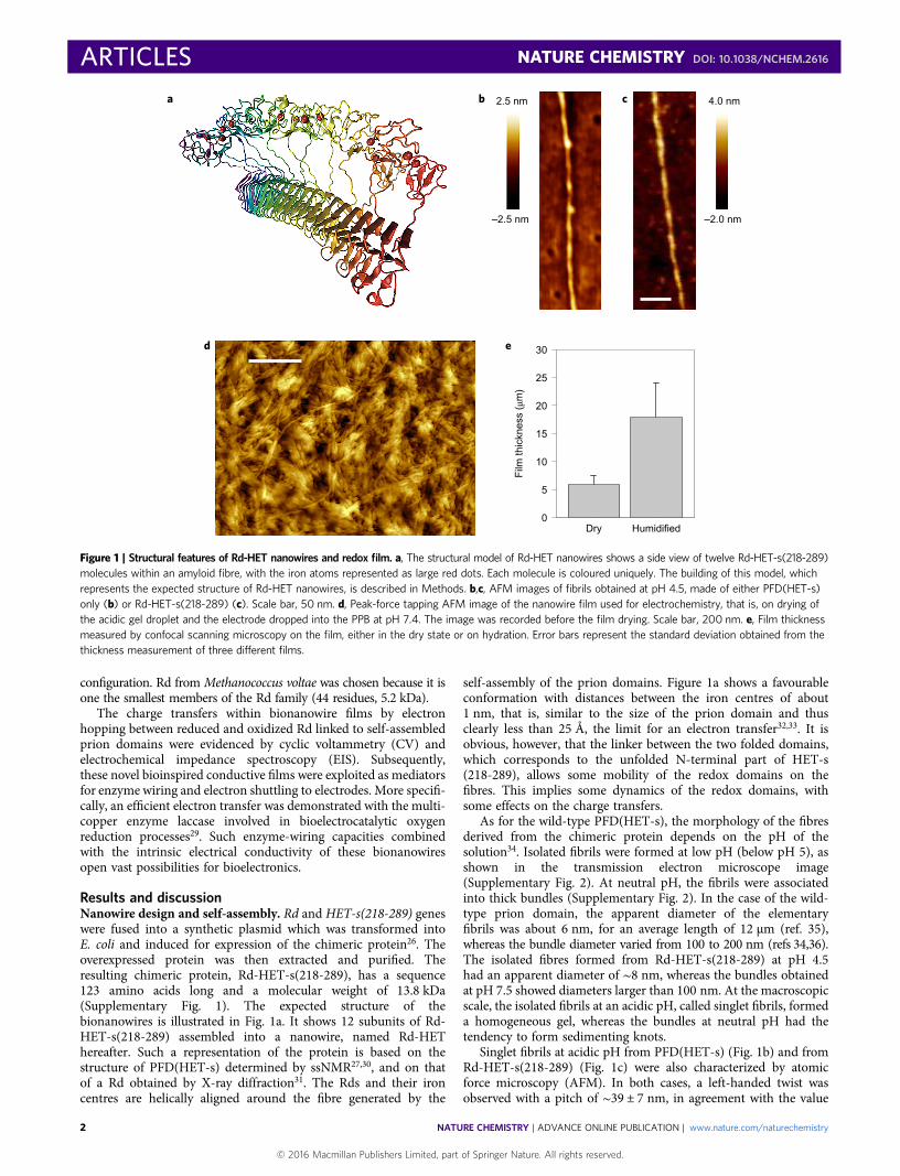
Results and discussionNanowire design and self-assembly. Rd and HET-s(218-289) geneswere fused into a synthetic plasmid which was transformed intoE. coli and induced for expression of the chimeric protein26. Theoverexpressed protein was then extracted and purified. Theresulting chimeric protein, Rd-HET-s(218-289), has a sequence123 amino acids long and a molecular weight of 13.8 kDa(Supplementary Fig. 1). The expected structure of thebionanowires is illustrated in Fig. 1a. It shows 12 subunits of Rd-HET-s(218-289) assembled into a nanowire, named Rd-HEThereafter. Such a representation of the protein is based on thestructure of PFD(HET-s) determined by ssNMR27,30, and on thatof a Rd obtained by X-ray diffraction31. The Rds and their ironcentres are helically aligned around the fibre generated by the
self-assembly of the prion domains. Figure 1a shows a favourableconformation with distances between the iron centres of about1 nm, that is, similar to the size of the prion domain and thusclearly less than 25 Å, the limit for an electron transfer32,33. It isobvious, however, that the linker between the two folded domains,which corresponds to the unfolded N-terminal part of HET-s(218-289), allows some mobility of the redox domains on thefibres. This implies some dynamics of the redox domains, withsome effects on the charge transfers.
As for the wild-type PFD(HET-s), the morphology of the fibresderived from the chimeric protein depends on the pH of thesolution34. Isolated fibrils were formed at low pH (below pH 5), asshown in the transmission electron microscope image(Supplementary Fig. 2). At neutral pH, the fibrils were associatedinto thick bundles (Supplementary Fig. 2). In the case of the wild-type prion domain, the apparent diameter of the elementaryfibrils was about 6 nm, for an average length of 12 µm (ref. 35),whereas the bundle diameter varied from 100 to 200 nm (refs 34,36).The isolated fibres formed from Rd-HET-s(218-289) at pH 4.5had an apparent diameter of ∼8 nm, whereas the bundles obtainedat pH 7.5 showed diameters larger than 100 nm. At the macroscopicscale, the isolated fibrils at an acidic pH, called singlet fibrils, formeda homogeneous gel, whereas the bundles at neutral pH had thetendency to form sedimenting knots.
Singlet fibrils at acidic pH from PFD(HET-s) (Fig. 1b) and fromRd-HET-s(218-289) (Fig. 1c) were also characterized by atomicforce microscopy (AFM). In both cases, a left-handed twist wasobserved with a pitch of ∼39 ± 7 nm, in agreement with the value
2.5 nm
–2.5 nm
30
25
20
15
10
5
0Dry Humidified
Film
thic
knes
s (μ
m)
4.0 nm
–2.0 nm
b ca
d e
Figure 1 | Structural features of Rd-HET nanowires and redox film. a, The structural model of Rd-HET nanowires shows a side view of twelve Rd-HET-s(218-289)molecules within an amyloid fibre, with the iron atoms represented as large red dots. Each molecule is coloured uniquely. The building of this model, whichrepresents the expected structure of Rd-HET nanowires, is described in Methods. b,c, AFM images of fibrils obtained at pH 4.5, made of either PFD(HET-s)only (b) or Rd-HET-s(218-289) (c). Scale bar, 50 nm. d, Peak-force tapping AFM image of the nanowire film used for electrochemistry, that is, on drying ofthe acidic gel droplet and the electrode dropped into the PPB at pH 7.4. The image was recorded before the film drying. Scale bar, 200 nm. e, Film thicknessmeasured by confocal scanning microscopy on the film, either in the dry state or on hydration. Error bars represent the standard deviation obtained from thethickness measurement of three different films.
ARTICLES NATURE CHEMISTRY DOI: 10.1038/NCHEM.2616
NATURE CHEMISTRY | ADVANCE ONLINE PUBLICATION | www.nature.com/naturechemistry2
© 2016 Macmillan Publishers Limited, part of Springer Nature. All rights reserved.

derived from cryoelectron microscopy37. The presence of Rd on thefibrils had no significant effect on the observed heights; the Rddomains were most probably swept by the tip because of the flexibilityof the linker between the two domains (Fig. 1a). This resulted in anapparent lower resolution of the fibril edges (Fig. 1b,c).
Electrochemistry of Rd-HET redox films. The spectroscopic(ultraviolet–visible light and electron paramagnetic resonancespectroscopy) properties of Rd on the surface of Rd-HETbionanowires were similar to those of Rd free in solution(Supplementary Fig. 3). According to the electrochemicalmeasurements (Supplementary Fig. 3), the redox properties of Rdon the nanowires were not altered either; the redox potential E1/2,which corresponds to the reversible monoelectronic Fe2+/3+ systemof Rd, was −0.12 V vs Ag/AgCl for both Rd alone and Rd-HET.
Electrochemical experiments were carried out to verify whetherRd-HET could facilitate electron transfer at the interface of theelectrode surface (surface-confined electron-transfer process) andelectron diffusion through Rd-HET films (diffusional electron-transfer process). To elucidate the electron-transfer process, twotypes of Rd-HET films, thin and thick films, were deposited at pH4 onto a glassy carbon electrode (GCE). For the thin film, the fibreadsorption on the GCE was allowed for 30 minutes. The electrodewas then rinsed with water to remove the unbound fibres and keeponly the fibres in a tight interaction. These so-called thin films hada thickness of ∼1.3 µm (Supplementary Fig. 4), which was muchmore than expected for a protein monolayer. Owing to the highaspect ratio (a diameter of ∼5 nm for an average length of 12 µm)and the flexibility of the bionanowires, the layer formed this way wasmore probably an intricate network than a real monolayer. The exactnature of the interaction between the fibres and the GCE is stillunder investigation. However, favourable electrostatic interactionsbetween the negatively charged GCE electrode and the positivelycharged proteins at pH 4.5 (isoelectric point (pI)(Rd-HET) = 7.7) arelikely to play a role. CV was used to investigate these bioelectrodesin a potassium phosphate buffer (PPB) at neutral pH (SupplementaryFig. 4). The redox wave at E1/2ox = −0.12 V vs Ag/AgCl had apeak-to-peak separation (ΔEp) of 2 mV, close to the theoreticalvalue of 0 mV expected for a surface-confined electron-transferprocess. The linear dependence of the peak currents as a functionof the scan rate revealed a fast and efficient electron transfer fromthe electrode to the first bionanowire layers (Supplementary Fig. 4).Thus, the electron-exchange rate between the Rd-HET thin film andthe electrode was not limited by diffusion processes within thisrange of scan rates. A surface coverage of Г = 6.2 × 10⁻¹¹ mol cm−2
for Rd-HET monomers was estimated by the integration of thecharge of the redox peaks at slow scan rates.
Owing to the protocol used for its preparation, the thick film wasa dense and intricate network of both short bundles and isolatedfibrils, as confirmed by peak-force tapping AFM (Fig. 1d). First,when still singlet fibrils the bionanowires were drop cast onto aGCE at pH 4 as a homogeneous gel; they were then left to dry.For the electrochemistry experiment, the electrode was dippedinto a PPB at neutral pH. At this pH, the bionanowires have the ten-dency to assemble and form bundles (Supplementary Fig. 2).However, as a result of their high concentration on the electrodesurface before the pH jump from pH 4 to pH 7.4, the nanowiresdo not have the ability to reorganize themselves into longbundles. Instead, short bundles that involve short sections of bio-nanowires, are formed. They are a few hundreds of nanometreslong (Fig. 1d), whereas the bundles formed at low concentrationsare tens of micrometres long (not shown). The obtained architectureis illustrated in Supplementary Fig. 6, and results in the formation ofa hydrogel that stabilizes the film on the electrode surface and keepssome softness. Indeed, whereas the ‘dry film’ was 6 µm thick, afterhumidification of the Rd-HET film a thickness of 18 µm wasmeasured (Fig. 1e and Supplementary Fig. 5). This swelling effectis consistent with that already observed in redox hydrogel films38.Furthermore, the Rd-HET film showed a remarkable stability overtime—CVs recorded periodically over six days showed a signalloss of only ∼20% (Supplementary Fig. 7). As control experiments,we observed that functionalized electrodes using adsorbed Rd as wellas mixtures of PFD(HET) and Rd (Supplementary Fig. 7) exhibitedonly low-intensity redox signals, probably because of the rapidrelease of Rd in solution. No redox signal was detected whenPFD(HET) was used alone.
For thick Rd-HET films, ΔEp was equal to 62 mV, close to thetheoretical value of 56.4 mV, as expected at a low scanning ratefor a reversible monoelectronic diffusion-controlled redox system(Fig. 2a). At increasing scan rates, the peak current linearlyincreased with the square root of the scan rate (Fig. 2b). Such behav-iour indicates that the electron transfer within the protein nanowirefilm was governed by linear diffusion39. Using the Randles–Sevcikequation, an apparent charge-transport diffusion coefficient (DCT)of (3.7 ± 0.5) × 10−12 cm2 s−1 was estimated from the slope of thelinear dependency shown in Fig. 2b, taking into account a filmthickness of 18 µm. The swelling effect indicated that the solventcould penetrate the film. Therefore, the ions (protons, Na+, Cl−, …)could diffuse within the film and thus contribute to the chargetransport. The same experiment was repeated for different electro-lyte concentrations between 0.025 and 0.5 M. Up to 0.1 M ofNaCl, no significant change of both the CVs and the peak-currentdependencies on the scan rate could be observed (Fig. 3b andSupplementary Fig. 8). For electrolyte concentrations above 0.1 M,
2 × 10–12
0
4 × 10–12
–0.4–1,000
1,000C
urre
nt (
nA)
Cur
rent
(nA
)
DC
T (
cm2
s–1 )
600
500
400
300
200
100
0
–500
500
0
a b c
–0.3 –0.2 0.2 0.05 0.10 0.15 0.20
Square root of scan rate (V1/2 s–1/2)
0.25 0.30 0.35 0 50 100 200 400
Added NaCI (mM)
–0.1 0.10.0
Potential (V vs Ag/AgCI)
Figure 2 | Electrochemistry of Rd-HET redox film. a, CV of a Rd-HET ‘thick’ film over a GCE in 0.1 M PPB, at pH 7.4. Scan rates are 5 (red), 10 (yellow),20 (green), 50 (blue) and 100 (purple) mV s–1. b, Scan-rate dependency study of peak current at different electrolyte concentrations. Peak currentscorrespond to the redox peak height on subtracting the capacitive component, which increases also with the scan rate. Anodic current (oxidation) withoutadded NaCl (black circles); with added 25 mM NaCl (red circles), 50 mM NaCl (green circles), 100 mM NaCl (blue circles), 200 mM NaCl (purple circles)and 500 mM NaCl (cyan circles). The continuous line corresponds to the linear regression on the data obtained in the absence of added NaCl. c, Plot of DCT
and the electrolyte concentration. The DCT values were extracted from scan-rate dependencies at different NaCl concentrations.
NATURE CHEMISTRY DOI: 10.1038/NCHEM.2616 ARTICLES
NATURE CHEMISTRY | ADVANCE ONLINE PUBLICATION | www.nature.com/naturechemistry 3
© 2016 Macmillan Publishers Limited, part of Springer Nature. All rights reserved.

the current intensity in the CV decreased because of film damage asa result of nanowire aggregation at high ionic strength (data notshown). For the different electrolyte concentrations, DCT was esti-mated based on the peak current versus scan-rate dependenciesand from the redox protein concentration within the film(Fig. 2c). It remained quite constant for electrolyte concentrationsup to 0.1 M. Moreover, CVs recorded on the same film at differentpH values (from 4.5 to 7.4) were basically the same (SupplementaryFig. 8). Therefore, current and the associated DCT values depend onneither the ionic strength nor the pH, which demonstrates that thecharge transfer monitored by electrochemistry within the films wasnot controlled by ionic or proton diffusion. Nevertheless, to preservethe electroneutrality the diffusion of ions and protons within thefilm was probably important to compensate the charge (electron)transfers. Therefore, the charge transfer within the thick film wasdetermined by electron transfers between the Rd units via ahopping mechanism. Furthermore, the alignment of the redoxcentres along the fibres was essential to obtain a fully reversible elec-troactive film. In fact, when the GCE was functionalized withPFD(HET) and Rd crosslinked using glutaraldehyde vapours, theredox system was poorly reversible with a ΔEp of 300 mV(Supplementary Fig. 9). These control experiments further high-lighted the unique redox properties of the Rd-HET bionanowirescompared with those of disordered redox protein films.
The association of Rd with a prion domain thus allowed the for-mation of a stable biofilm that kept the local concentration of Rd onthe electrode surface high enough to have a good electrochemicalsignal. Furthermore, it induced the organization of a densenetwork of Rd, that is, close enough to each other to allow for anefficient electron transport between Fe centres throughout dozensof micrometres, most probably by an electron-hopping mechanism.Such formalism has been applied to describe electron hoppingwithin self-assembled redox polymers40–42. For comparison, redoxpolymers based on ferrocene or osmium complexes attached to apolymer backbone exhibit DCT coefficient values that range from10−6 to 10−12 cm2 s−1 (ref. 38). A diffusion coefficient for Rd-HETfilms in the lower limit might result in the larger protein–proteindistance as well as in a lower redox-centre mobility as comparedwith small redox molecules involved in these redox polymers.
EIS43 allows an insight into the redox phenomena that occurswithin electroactive films made of redox polymers44,45. The same
three-electrode set-up as used to record CVs was used; the over-potential was fixed at the redox potential of Rd (−0.12 V vs Ag/AgCl)and small-amplitude oscillations of various frequencies wereapplied. Therefore, only the impedance caused by the redoxphenomenon was monitored in this experiment. The Nyquist plotfrom the EIS measurements for the modified electrode fittedperfectly the equivalent circuit model displayed at the top ofFig. 3. This model comprised two resistance elements: Rsol for theohmic resistance of the electrolyte solution and RCT for thecharge-transfer resistance between the film and the GCE. Onedouble-layer capacitance (CDL) and a Warburg impedance ZWelement for the linear electron diffusion within the electroactivefilm completed the circuit44–47. The value of Rsol corresponded tothe impedance where the Nyquist plot crossed the ‘Re Z’ axis athigh frequencies (Fig. 3, inset), Rsol = 11.5 ± 0.5 Ω cm2. The high-frequency semicircle of the Nyquist diagram (Fig. 3b, below 41 Hz)corresponded to the charge-transfer resistance in parallel to the double-layer capacitance, RCT = 450 ± 20Ω cm2 and CDL = 14.8 ± 0.5 µF cm−2.At low frequencies (Fig. 3a, between 9.6 and 0.05 Hz), two succes-sive linear parts were observed. The linear part for frequenciesabove 1 Hz had a slope close to one, whereas that between 1 and0.05 Hz was almost vertical. Such a broken slope is characteristicof a restricted finite-length diffusion process of the diffusingredox species44–47. Between 9.6 and 1 Hz, the impedance adoptedthe form of a characteristic Warburg element with a slope of onein the complex impedance plane, ZW = 560 ± 20 Ω cm2. When themodulation frequency was lower, the impedance described a ‘block-ing’ surface, which means that the redox species were confinedwithin the electroactive film44–47. In our case, the only way toexplain such a phenomenon is via an electron-hopping mechanismbetween the Fe2+/Fe3+ redox centres of the nanowires within thefilm. The contribution of proton or ionic diffusion to the charge-transport impedance (ZW) can be excluded. Indeed, protons andions could freely diffuse between the bulk and the film. Thus, iftheir diffusion could control the charge-transport impedance, acompletely different behaviour would be observed in the Nyquistplot43,46,48, that is, a semi-infinite diffusion or finite-length diffusionwith transmissive boundary conditions. In the case that theirdiffusion constant would not be modified between the bulk andthe film, the slope of the Nyquist plot would remain close to 1 asexpected for a semi-infinite process43,46. In the case that a con-centration gradient would appear within the electroactive filmbecause their diffusion constant would become slower due to thelocal viscosity, the Nyquist plot should follow a semi-circle at lowfrequencies, as expected for a transmissive finite-length diffusionprocess43,48. In the ideal case, the slope of the Nyquist plot at low fre-quency should be vertical (with an angle of 90°) for a restrictedfinite-length diffusion process44–48. That the angle we observedwas smaller than 90° reflected some inhomogeneity in the electro-active film thickness45,48, that is, the roughness of the interface, ascould be seen by confocal microscopy (Supplementary Fig. 5). Theway that the interface inhomogeneity was taken into account for thefitting to the electric circuit is explained in Methods.
Furthermore, these features enabled the identification of two suc-cessive phenomena that governed, in equal parts, the electrochemi-cal kinetics: electron transfer at the interface Rd-HET/electrode,RCT = 450 ± 20 Ω cm2, and the diffusion of electrons inside theRd-HET film, ZW = 560 ± 20 Ω cm2. Considering a thickness of18 µm and an electrode diameter of 3 mm, it was possible to esti-mate from the ZW value the electrical conductivity of the film tobe 3.1 µS cm−1.
The conductivity of protein films in the dry state has already beeninvestigated, in particular for amyloid fibrils14,16–19,49. The dominantcharge-transport mechanism has been attributed to protonicconductivity14,49 and the organization of the proteins into fibrilsincreased the conductivity by several orders of magnitude14. It was
a
00
40
–40 × 103
–80 × 103
–120 × 103
WW
–160 × 103
80
1 Hz
0.05 Hz
CDL
Rsol
RCT
ZW
2.1 Hz
Im Z
(Ω
)
Re Z (Ω) × 103
b
–5,000
00 5,000
41 Hz
127 Hz
9.6 Hz
Im Z
(Ω
)
Re Z (Ω)
Figure 3 | EIS on Rd-HET redox film. a, Nyquist plot of impedance spectraof Rd-HET drop cast on a GCE in 0.1 M phosphate buffer (pH 7.4). Inset,equivalent circuit used to fit the experimental data. b, Zoom at the high-frequency impedance range. The frequency sweep was from 50 kHz to0.05 Hz. Impedance measurements were performed at −0.12 V vs Ag/AgClwith an a.c. amplitude of 10 mV. Experimental (dots) and fitted data (lines)are presented.
ARTICLES NATURE CHEMISTRY DOI: 10.1038/NCHEM.2616
NATURE CHEMISTRY | ADVANCE ONLINE PUBLICATION | www.nature.com/naturechemistry4
© 2016 Macmillan Publishers Limited, part of Springer Nature. All rights reserved.
interesting to check whether the observed electron-hopping mech-anism in the present nanowires caused by a redox process in sol-ution might result in an additional conductivity mechanism inthe dry state. For that purpose, current–voltage (I–V) measurementswere performed on dried thick films made of either PFD(HET)alone or Rd-HET (Supplementary Fig. 10). Some conductivity wasobserved for fibres made of PFD(HET) alone, probably caused by pro-tonic and, to some extent, ionic conductivity. However, the I–V curveshowed higher current values for Rd-HET and thus a lower resistancevalue of 50 MΩ as compared with the 143 MΩ for PFD(HET). Thissuggested that the possibility to have electron hopping provided anadditional conductivity to the fibres. However, this remains to be con-firmed. From these data, it was possible to estimate the electrical d.c.conductivity of the Rd-HET film to be 2.4 µS cm−1. Both types of a.c.and d.c. conductivity measurements (EIS and I–V, respectively) thusgave consistent values of a few microsiemens per centimetre, whichare similar to those reported for natural biofilms made of microbialnanowire networks50.
Application of Rd-HET nanowires for enzyme wiring. Encouragedby the efficient electron transport of the Rd-HET redox films, we
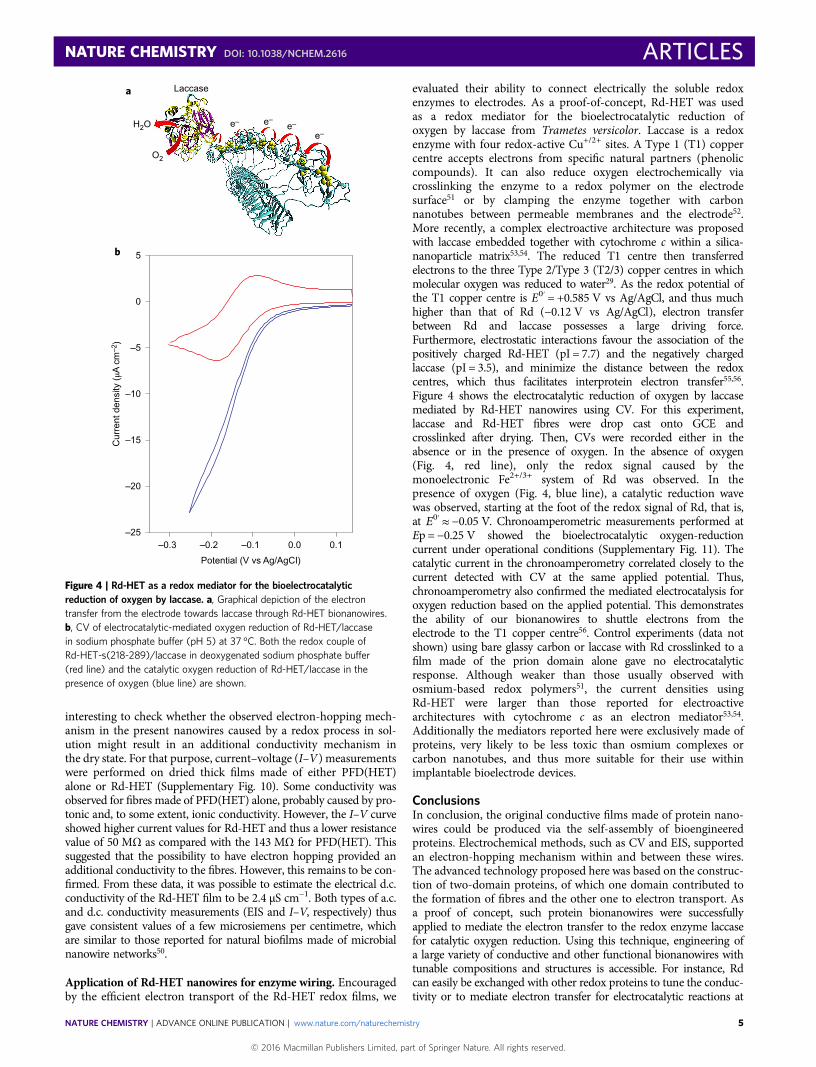
evaluated their ability to connect electrically the soluble redoxenzymes to electrodes. As a proof-of-concept, Rd-HET was usedas a redox mediator for the bioelectrocatalytic reduction ofoxygen by laccase from Trametes versicolor. Laccase is a redoxenzyme with four redox-active Cu+/2+ sites. A Type 1 (T1) coppercentre accepts electrons from specific natural partners (phenoliccompounds). It can also reduce oxygen electrochemically viacrosslinking the enzyme to a redox polymer on the electrodesurface51 or by clamping the enzyme together with carbonnanotubes between permeable membranes and the electrode52.More recently, a complex electroactive architecture was proposedwith laccase embedded together with cytochrome c within a silica-nanoparticle matrix53,54. The reduced T1 centre then transferredelectrons to the three Type 2/Type 3 (T2/3) copper centres in whichmolecular oxygen was reduced to water29. As the redox potential ofthe T1 copper centre is E0′ = +0.585 V vs Ag/AgCl, and thus muchhigher than that of Rd (−0.12 V vs Ag/AgCl), electron transferbetween Rd and laccase possesses a large driving force.Furthermore, electrostatic interactions favour the association of thepositively charged Rd-HET (pI = 7.7) and the negatively chargedlaccase (pI = 3.5), and minimize the distance between the redoxcentres, which thus facilitates interprotein electron transfer55,56.Figure 4 shows the electrocatalytic reduction of oxygen by laccasemediated by Rd-HET nanowires using CV. For this experiment,laccase and Rd-HET fibres were drop cast onto GCE andcrosslinked after drying. Then, CVs were recorded either in theabsence or in the presence of oxygen. In the absence of oxygen(Fig. 4, red line), only the redox signal caused by themonoelectronic Fe2+/3+ system of Rd was observed. In thepresence of oxygen (Fig. 4, blue line), a catalytic reduction wavewas observed, starting at the foot of the redox signal of Rd, that is,at E0′≈ −0.05 V. Chronoamperometric measurements performed atEp = −0.25 V showed the bioelectrocatalytic oxygen-reductioncurrent under operational conditions (Supplementary Fig. 11). Thecatalytic current in the chronoamperometry correlated closely to thecurrent detected with CV at the same applied potential. Thus,chronoamperometry also confirmed the mediated electrocatalysis foroxygen reduction based on the applied potential. This demonstratesthe ability of our bionanowires to shuttle electrons from theelectrode to the T1 copper centre56. Control experiments (data notshown) using bare glassy carbon or laccase with Rd crosslinked to afilm made of the prion domain alone gave no electrocatalyticresponse. Although weaker than those usually observed withosmium-based redox polymers51, the current densities usingRd-HET were larger than those reported for electroactivearchitectures with cytochrome c as an electron mediator53,54.Additionally the mediators reported here were exclusively made ofproteins, very likely to be less toxic than osmium complexes orcarbon nanotubes, and thus more suitable for their use withinimplantable bioelectrode devices.
ConclusionsIn conclusion, the original conductive films made of protein nano-wires could be produced via the self-assembly of bioengineeredproteins. Electrochemical methods, such as CV and EIS, supportedan electron-hopping mechanism within and between these wires.The advanced technology proposed here was based on the construc-tion of two-domain proteins, of which one domain contributed tothe formation of fibres and the other one to electron transport. Asa proof of concept, such protein bionanowires were successfullyapplied to mediate the electron transfer to the redox enzyme laccasefor catalytic oxygen reduction. Using this technique, engineering ofa large variety of conductive and other functional bionanowires withtunable compositions and structures is accessible. For instance, Rdcan easily be exchanged with other redox proteins to tune the conduc-tivity or to mediate electron transfer for electrocatalytic reactions at
a
b 5
0
–5
–10
–15
–20
–25–0.3 –0.2 –0.1 0.10.0
Potential (V vs Ag/AgCI)
Cur
rent
den
sity
(μA
cm
–2)
Laccase
H2O
O2
e– e–e–
e–
Figure 4 | Rd-HET as a redox mediator for the bioelectrocatalyticreduction of oxygen by laccase. a, Graphical depiction of the electrontransfer from the electrode towards laccase through Rd-HET bionanowires.b, CV of electrocatalytic-mediated oxygen reduction of Rd-HET/laccasein sodium phosphate buffer (pH 5) at 37 °C. Both the redox couple ofRd-HET-s(218-289)/laccase in deoxygenated sodium phosphate buffer(red line) and the catalytic oxygen reduction of Rd-HET/laccase in thepresence of oxygen (blue line) are shown.
NATURE CHEMISTRY DOI: 10.1038/NCHEM.2616 ARTICLES
NATURE CHEMISTRY | ADVANCE ONLINE PUBLICATION | www.nature.com/naturechemistry 5
© 2016 Macmillan Publishers Limited, part of Springer Nature. All rights reserved.
optimal overpotentials. This flexibility opens up many potential appli-cations based on pure protein bio(nano)electronics. Within biomedicaldevices, for instance, pure protein biosensors powered by pure proteinbiofuel cells in living organisms that harvest the needed energy directlyfrom the organism (for example, glucose) can be anticipated57,58.
MethodsThe plasmid construct and the expression and purification of the different proteinsused in this work are described in the Supplementary Information, together with thevarious biophysical methods needed for their structural characterization.
Model of the Rd-HET nanowire (Fig. 1a). For the amyloid fibre structure, thessNMR structure of PFD(HET) (Protein Data Bank (PDB) entry 2RNM) was used.The M. voltae Rd structure was generated by analogy with that of Pyrococcus abyssiRd (PDB entry 1YK5) with MODELLER and refined with the CHARMM force fieldin implicit solvent. The chimeric protein structure was obtained by fusing the twostructures with MODELLER and slightly refined with CHARMM. The picture wasgenerated with VMD (Illinois University).
AFM. Fibrils were diluted to a final concentration of 0.28 µM in HCl 0.1 mM andleft to adsorb overnight at 4 °C on glass slides cleaned with plasma O2. After removalof the solution, the samples were left to dry. Images were recorded at a scanningspeed of 0.5 Hz in the tapping mode in air with a Dimension 3100 (Bruker) usingSi3N4 cantilevers of a spring constant of 0.4 N m−1, and were analysed usingNanoscope (Bruker). PeakForce Tapping AFM analysis of the thick film wasperformed on Dimension ICON (Bruker). ScanAsyst Air tip (Bruker) with a springconstant of 0.35 N m−1, as determined by the thermal tune method, was used. Theused PeakForce Setpoint value was 150 pN.
Electrochemistry. CV was performed using a Biologic potentiostat PS200. A three-electrode electrochemical cell with a working volume of 10 ml was used. Theworking electrode was a GCE (diameter, 3 mm) purchased from Biologic. Thereference and counter electrodes were Ag/AgCl and platinum, respectively. Toprepare the film, 30 µl of Rd-HET (390 µM) was drop cast onto a GCE and allowedto dry overnight before performing the electrochemical characterizations.
The surface coverages of redox-active species confined to the electrodes werequantified using equation (1).
T = Q/nFA (1)
where Q is the faradaic charge transferred across the film39 (determined byintegration of anodic peaks of the cyclic voltammogram at low scanning rates(1 mV s–1)), n is the number of electrons (that is, n = 1) and A (cm2) is the electrodesurface area given a diameter of 3 mm.
The apparent charge transport, DCT, was obtained using the Randles–Sevcikequation (2):
ip = 269,000n3/2AD1/2CTCv
1/2 (2)
where ip (A) is the maximum current on background subtraction, C (mol cm–1) isthe protein concentration and v (V s–1) is the scan rate. The protein concentrationwithin the film was estimated by taking into account the amount of proteins presentwithin the deposited drop and the volume of the film on hydration. Then, DCT wasestimated from the slope of the linear dependency of ip with v1/2 (Fig. 2b).
For the electrocatalytic reduction of oxygen, 10 µl of Rd-HET (720 µM) and 5 µlof laccase (T. versicolor) at 5 mg ml–1 (stock solution prepared in sodium phosphatebuffer at pH 5) were drop cast onto a GCE and dried overnight. The pI for Rd-HETwas estimated from the amino acid sequence with ExPASy. The electrode wasexposed to glutaraldehyde vapour for ten minutes to crosslink Rd-HET and laccase.Experiments were initiated one hour later. The experiments were performed insodium phosphate buffer at pH 5 (laccase is active at acidic pH) in the presence andabsence of oxygen at 37 °C.
a.c. conductivity characterizations performed by EIS. The frequency sweep wasfrom 50 kHz to 0.05 Hz with an a.c. amplitude of 10 mV. The CVs were performedbefore the EIS measurements. The bias potential applied during the impedancemeasurement was calculated by (Ep,a + Ep,c)/2, where Ep,a and Ep,c were the anodicand cathodic peak potentials obtained from the CV. The data were fitted with theZView software (Scribner Associates Inc.) by using an appropriate equivalentelectrical circuit model. The equivalent circuit used constant phase elements (CPEs)instead of capacitances to account for imperfections of the electrochemical interfacecaused by surface inhomogeneity on the modified electrode59. The impedance of aCPE is given by:
ZCPE = Q−1(jω)−α
whereQ is the amplitude of the CPE, ω is the angular frequency and α is an exponentthat is a real number and varies between 0 and 1. When α = 1, a purely capacitivebehaviour is observed (that is, Q = C).
All the experiments were conducted in an anaerobic glovebox to prevent theaction of oxygen at room temperature (20 ± 1 °C). For the mediated electron transferof catalytic oxygen reduction, experiments were conducted outside the gloveboxunder ambient air at 37 °C.
Received 22 July 2015; accepted 16 August 2016;published online 10 October 2016
References1. Malvankar, N. S. & Lovley, D. R. Microbial nanowires: a new paradigm for
biological electron transfer and bioelectronics. ChemSusChem 5,1039–1046 (2012).
2. Qian, F. & Li, Y. Biomaterials: a natural source of nanowires. Nat. Nanotechnol.6, 538–539 (2011).
3. Pfeffer, C. et al. Filamentous bacteria transport electrons over centimetredistances. Nature 491, 218–221 (2012).
4. Reardon, P. N. & Mueller, K. T. Structure of the type IVa major pilin from theelectrically conductive bacterial nanowires of Geobacter sulfurreducens. J. Biol.Chem. 288, 29260–29266 (2013).
5. Malvankar, N. S., Tuominen, M. T. & Lovley, D. R. Lack of cytochromeinvolvement in long-range electron transport through conductive biofilms andnanowires of Geobacter sulfurreducens. Energy Environ. Sci. 5, 8651–8659 (2012).
6. Malvankar, N. S., Tuominen, M. T. & Lovley, D. R. Comment on ‘On electricalconductivity of microbial nanowires and biofilms’. Energy Environ. Sci. 5,6247–6249 (2012).
7. Bonanni, P. S., Massazza, D. & Busalmen, J. P. Stepping stones in the electrontransport from cells to electrodes in Geobacter sulfurreducens biofilms.Phys. Chem. Chem. Phys. 15, 10300–10306 (2013).
8. Strycharz-Glaven, S. M., Snider, R. M., Guiseppi-Elie, A. & Tender, L. M. On theelectrical conductivity of microbial nanowires and biofilms. Energy Environ. Sci.4, 4366–4379 (2011).
9. Knowles, T. P. J. & Buehler, M. J. Nanomechanics of functional and pathologicalamyloid materials. Nat. Nanotechnol. 6, 469–479 (2011).
10. Mankar, S., Anoop, A., Sen, S. &Maji, S. K. Nanomaterials: amyloids reflect theirbrighter side. Nano Rev. 2, 6032–6043 (2011).
11. Gras, S. L. in Advances in Chemical Engineering Vol. 35 (ed. Rudy, J. K.) 161–209(Academic, 2009).
12. Scheibel, T. et al. Conducting nanowires built by controlled self-assembly ofamyloid fibers and selective metal deposition. Proc. Natl Acad. Sci. USA 100,4527–4532 (2003).
13. Kholkin, A., Amdursky, N., Bdikin, I., Gazit, E. & Rosenman, G. Strongpiezoelectricity in bioinspired peptide nanotubes. ACS Nano 4, 610–614 (2010).
14. Amit, M. et al. Hybrid proton and electron transport in peptide fibrils. Adv.Funct. Mater. 24, 5873–5880 (2014).
15. Berger, O. et al. Light-emitting self-assembled peptide nucleic acids exhibit bothstacking interactions and Watson–Crick base pairing. Nat. Nanotechnol. 10,353–360 (2015).
16. del Mercato, L. L. et al. Charge transport and intrinsic fluorescence in amyloid-like fibrils. Proc. Natl Acad. Sci. USA 104, 18019–18024 (2007).
17. Amit, M., Cheng, G., Hamley, I. W. & Ashkenasy, N. Conductance of amyloid-based peptide filaments: structure & function relations. Soft Matter 8,8690–8696 (2012).
18. Creasey, R. C. G., Shingaya, Y. & Nakayama, T. Improved electrical conductancethrough self-assembly of bioinspired peptides into nanoscale fibers.Mater. Chem. Phys. 158, 52–59 (2015).
19. Domigan, L. J., Healy, J. P., Meade, S. J., Blaikie, R. J. & Gerrard, J. A. Controllingthe dimensions of amyloid fibrils: toward homogenous components forbionanotechnology. Biopolymers 97, 123–133 (2012).
20. Herland, A. et al. Electroactive luminescent self-assembled bio-organicnanowires: integration of semiconducting oligoelectrolytes withinamyloidogenic proteins. Adv. Mater. 17, 1466–1471 (2005).
21. Rizzo, A., Solin, N., Lindgren, L. J., Andersson, M. R. & Inganäs, O. White lightwith phosphorescent protein fibrils in OLEDs. Nano Lett. 10, 2225–2230 (2010).
22. Bolisetty, S., Adamcik, J., Heier, J. & Mezzenga, R. Amyloid directed synthesis oftitanium dioxide nanowires and their applications in hybrid photovoltaicdevices. Adv. Funct. Mater. 22, 3424–3428 (2012).
23. Li, C., Adamcik, J. & Mezzenga, R. Biodegradable nanocomposites of amyloidfibrils and graphene with shape-memory and enzyme-sensing properties.Nat. Nanotechnol. 7, 421–427 (2012).
24. Baldwin, A. J. et al. Cytochrome display on amyloid fibrils. J. Am. Chem. Soc.128, 2162–2163 (2006).
25. Saupe, S. J. The [Het-s] prion of Podospora anserina and its role in heterokaryonincompatibility. Semin. Cell Dev. Biol. 22, 460–468 (2011).
26. Balguerie, A. et al. Domain organization and structure–function relationship ofthe HET-s prion protein of Podospora anserina. EMBO J. 22, 2071–2081 (2003).
27. Wasmer, C. et al. Amyloid fibrils of the HET-s(218–289) prion form a β solenoidwith a triangular hydrophobic core. Science 319, 1523–1526 (2008).
28. Meyer, J. Iron–sulfur protein folds, iron–sulfur chemistry, and evolution. J. Biol.Inorg. Chem. 13, 157–170 (2008).
ARTICLES NATURE CHEMISTRY DOI: 10.1038/NCHEM.2616
NATURE CHEMISTRY | ADVANCE ONLINE PUBLICATION | www.nature.com/naturechemistry6
© 2016 Macmillan Publishers Limited, part of Springer Nature. All rights reserved.

29. Solomon, E. I., Sundaram, U. M. & Machonkin, T. E. Multicopper oxidases andoxygenases. Chem. Rev. 96, 2563–2606 (1996).
30. Van Melckebeke, H. et al. Atomic-resolution three-dimensional structure ofHET-s(218–289) amyloid fibrils by solid-state NMR spectroscopy. J. Am. Chem.Soc. 132, 13765–13775 (2010).
31. Bonisch, H., Schmidt, C. L., Bianco, P. & Ladenstein, R. Ultrahigh-resolutionstudy on Pyrococcus abyssi rubredoxin. I. 0.69 A X-ray structure of mutant W4L/R5S. Acta Cryst. D 61, 990–1004 (2005).
32. Page, C. C., Moser, C. C., Chen, X. & Dutton, P. L. Natural engineeringprinciples of electron tunnelling in biological oxidation-reduction. Nature 402,47–52 (1999).
33. Winkler, J. R. & Gray, H. B. Long-range electron tunneling. J. Am. Chem. Soc.136, 2930–2939 (2014).
34. Sabaté, R. et al. Prion and non-prion amyloids of the HET-s prion formingdomain. J. Mol. Biol. 370, 768–783 (2007).
35. Doussineau, T. et al. Mass determination of entire amyloid fibrils by using massspectrometry. Angew. Chem. Int. Ed. 55, 2340–2344 (2016).
36. Siemer, A. et al. 13C, 15N resonance assignment of parts of the HET-s prionprotein in its amyloid form. J. Biomol. NMR 34, 75–87 (2006).
37. Mizuno, N., Baxa, U. & Steven, A. C. Structural dependence of HET-s amyloidfibril infectivity assessed by cryoelectron microscopy. Proc. Natl Acad. Sci. USA108, 3252–3257 (2011).
38. Mao, F., Mano, N. & Heller, A. Long tethers binding redox centers to polymerbackbones enhance electron transport in enzyme ‘wiring’ hydrogels. J. Am.Chem. Soc. 125, 4951–4957 (2003).
39. Bard, A. J. & Faulkner, L. R. in Electrochemical Methods: Fundamentals andApplications 2nd edn (eds Allen, J. & Bard, L. R. F.) 580 (John Wiley &Sons, 2001).
40. Laviron, E. A multilayer model for the study of space distributed redox modifiedelectrodes. Part I. Description and discussion of the model. J. Electroanal. Chem.Interfacial Electrochem. 112, 1–9 (1980).
41. Blauch, D. N. & Saveant, J. M. Dynamics of electron hopping in assemblies ofredox centers. Percolation and diffusion. J. Am. Chem. Soc. 114,3323–3332 (1992).
42. Andrieux, C. P. & Savéant, J. M. Electron transfer through redox polymer films.J. Electroanal. Chem. Interfacial Electrochem. 111, 377–381 (1980).
43. Barsoukov, E. & Macdonald, J. R. Impedance Spectroscopy: Theory, Experiment,and Applications 2nd edn (John Wiley & Sons, 2005).
44. Gabrielli, C., Haas, O. & Takenouti, H. Impedance analysis of electrodesmodified with a reversible redox polymer film. J. Appl. Electrochem. 17,82–90 (1987).
45. Musiani, M. M. Characterization of electroactive polymer layers byelectrochemical impedance spectroscopy (EIS). Electrochim. Acta 35,1665–1670 (1990).
46. Ho, C., Raistrick, I. D. & Huggins, R. A. Application of A-C techniques to thestudy of lithium diffusion in tungsten trioxide thin films. J. Electrochem. Soc.127, 343–350 (1980).
47. Bisquert, J., Garcia-Belmonte, G., Bueno, P., Longo, E. & Bulhões, L. O. S.Impedance of constant phase element (CPE)-blocked diffusion in filmelectrodes. J. Electroanal. Chem. 452, 229–234 (1998).
48. Criado, C., Galán-Montenegro, P., Velásquez, P. & Ramos-Barrado, J. R.Diffusion with general boundary conditions in electrochemical systems.J. Electroanal. Chem. 488, 59–63 (2000).
49. Ordinario, D. D. et al. Bulk protonic conductivity in a cephalopod structuralprotein. Nat. Chem. 6, 596–602 (2014).
50. Malvankar, N. S. et al. Tunable metallic-like conductivity in microbial nanowirenetworks. Nat. Nanotechnol. 6, 573–579 (2011).
51. Rengaraj, S., Kavanagh, P. & Leech, D. A comparison of redox polymer andenzyme co-immobilization on carbon electrodes to provide membrane-lessglucose/O2 enzymatic fuel cells with improved power output and stability.Biosens. Bioelectron. 30, 294–299 (2011).
52. Rubenwolf, S. et al. Carbon electrodes for direct electron transfer type laccasecathodes investigated by current density–cathode potential behavior.Biosens. Bioelectron. 26, 841–845 (2010).
53. Feifel, S. C., Kapp, A. & Lisdat, F. Electroactive nanobiomolecular architecturesof laccase and cytochrome c on electrodes: applying silica nanoparticles asartificial matrix. Langmuir 30, 5363–5367 (2014).
54. Feifel, S. C., Kapp, A., Ludwig, R. & Lisdat, F. Nanobiomolecular multiproteinclusters on electrodes for the formation of a switchable cascadic reaction scheme.Angew. Chem. Int. Ed. 53, 5676–5679 (2014).
55. Winkler, J. R., Gray, H. B., Prytkova, T. R., Kurnikov, I. V. & Beratan, D. N. inBioelectronics: From Theory to Applications (eds Willner, I. & Katz, E.) 15–33(Wiley-VCH, 2005).
56. Piontek, K., Antorini, M. & Choinowski, T. Crystal structure of a laccase fromthe fungus Trametes versicolor at 1.90-Å resolution containing a full complementof coppers. J. Biol. Chem. 277, 37663–37669 (2002).
57. Le Goff, A., Holzinger, M. & Cosnier, S. Enzymatic biosensors based onSWCNT-conducting polymer electrodes. Analyst 136, 1279–1287 (2011).
58. Holzinger, M., Le Goff, A. & Cosnier, S. Carbon nanotube/enzyme biofuel cells.Electrochim. Acta 82, 179–190 (2012).
59. Daniels, J. S. & Pourmand, N. Label-free impedance biosensors: opportunitiesand challenges. Electroanalysis 19, 1239–1257 (2007).
AcknowledgementsWe thank D. Fenel and G. Schoehn from the IBS/UVHCI platform of the Partnership forStructural Biology in Grenoble (PSB/IBS) for the electron microscopy. We thank S. Saupefor the gift of pET24a(+)-HET-s(218-289)-His6 and S. Crouzy for his help in building thestructural model. AFM measurements were performed on the Commissariat à l’énergieatomique (CEA) Minatec Nanocharacterization Platform (PFNC). The present work wasalso partially supported by the Labex ARCANE (ANR-11-LABX-0003-01). L.A. and A.Rare indebted to CEA for the funding of their PhD fellowships. V.F. and P.R. thankN. Mermilliod and E. Molva, respectively heads of the Transverse Energy and theNanoscience programs of the CEA, for their scientific and financial support. We thankT. Martin for the careful reading of the manuscript.
Author contributionsC.H., N.D., M.F. and V.F. realized the design of the protein nanowire. C.H., L.A. and N.D.developed the protocol for the chimeric protein production in bacteria and purification.C.H., L.A., C.V., D.M., V.B., N.D. and V.F. performed the biophysical characterization ofthe bionanowires. S.R., L.A., K.E., C.G., A.L.B.M., A.L.-G., M.H. and N.D. carried out theelectrochemical characterization of the bionanowires and L.A., A.R. and P.R. performed theelectrical characterizations of the bionanowires. S.R., K.E., A.L.-G. and M.H. designed theelectrode functionalized with nanowires and laccase and realized the experiments. M.F.,V.B., M.H. and V.F. were responsible for the project management. L.A., S.R., A.L.-G. andV.F. prepared the manuscript. All the authors discussed the results and commented onthe manuscript.
Additional informationSupplementary information is available in the online version of the paper. Reprints andpermissions information is available online at www.nature.com/reprints. Correspondence andrequests for materials should be addressed to M.H. and V.F.
Competing financial interestsThe authors declare no competing financial interests.
NATURE CHEMISTRY DOI: 10.1038/NCHEM.2616 ARTICLES
NATURE CHEMISTRY | ADVANCE ONLINE PUBLICATION | www.nature.com/naturechemistry 7
© 2016 Macmillan Publishers Limited, part of Springer Nature. All rights reserved.